KR101965750B1 - Elastomeric draft gear for a railcar - Google Patents
Elastomeric draft gear for a railcar Download PDFInfo
- Publication number
- KR101965750B1 KR101965750B1 KR1020147009295A KR20147009295A KR101965750B1 KR 101965750 B1 KR101965750 B1 KR 101965750B1 KR 1020147009295 A KR1020147009295 A KR 1020147009295A KR 20147009295 A KR20147009295 A KR 20147009295A KR 101965750 B1 KR101965750 B1 KR 101965750B1
- Authority
- KR
- South Korea
- Prior art keywords
- housing
- compressible
- compressible resilient
- rigid member
- central axis
- Prior art date
Links
Images


Classifications
-
- B—PERFORMING OPERATIONS; TRANSPORTING
- B61—RAILWAYS
- B61G—COUPLINGS; DRAUGHT AND BUFFING APPLIANCES
- B61G9/00—Draw-gear
- B61G9/04—Draw-gear combined with buffing appliances
- B61G9/06—Draw-gear combined with buffing appliances with rubber springs
-
- B—PERFORMING OPERATIONS; TRANSPORTING
- B61—RAILWAYS
- B61G—COUPLINGS; DRAUGHT AND BUFFING APPLIANCES
- B61G9/00—Draw-gear
- B61G9/04—Draw-gear combined with buffing appliances
- B61G9/10—Draw-gear combined with buffing appliances with separate mechanical friction shock-absorbers
-
- B—PERFORMING OPERATIONS; TRANSPORTING
- B61—RAILWAYS
- B61G—COUPLINGS; DRAUGHT AND BUFFING APPLIANCES
- B61G9/00—Draw-gear
- B61G9/20—Details; Accessories
-
- Y—GENERAL TAGGING OF NEW TECHNOLOGICAL DEVELOPMENTS; GENERAL TAGGING OF CROSS-SECTIONAL TECHNOLOGIES SPANNING OVER SEVERAL SECTIONS OF THE IPC; TECHNICAL SUBJECTS COVERED BY FORMER USPC CROSS-REFERENCE ART COLLECTIONS [XRACs] AND DIGESTS
- Y10—TECHNICAL SUBJECTS COVERED BY FORMER USPC
- Y10T—TECHNICAL SUBJECTS COVERED BY FORMER US CLASSIFICATION
- Y10T29/00—Metal working
- Y10T29/49—Method of mechanical manufacture
- Y10T29/49826—Assembling or joining
Landscapes
- Engineering & Computer Science (AREA)
- Mechanical Engineering (AREA)
- Gears, Cams (AREA)
- Springs (AREA)
- Vibration Dampers (AREA)
- Vibration Prevention Devices (AREA)
Abstract
드래프트 기어 조립체는 하우징 및 그 안에 서로 일렬로 배치된 복수 개의 압축성 탄성 스프링을 포함하는 탄성 스프링 스택을 포함한다. 각 압축성 탄성 스프링은 압축성 탄성 패드, 상기 압축성 탄성 패드의 일 단부면과 직접 접촉하도록 포지셔닝된 강성부재, 강성부재의 두께를 통한 중심개구, 압축성 탄성 패드의 일 단부면상에 축방향으로 직립해 있는 교대로서, 강성부재의 두께를 통해 형성된 중심개구 내에 수용되도록 크기가 설정된 주변면이 있는 상기 교대, 그리고 중심축에 대해 실질적으로 가로놓인 면에서 축방향 교대의 말단부상에 배치된 환형 립을 포함하며, 상기 강성부재의 환형 두께 부분은 압축성 탄성 패드의 단부면과 환형 립의 내면 사이에 케이징된다.The draft gear assembly includes a housing and an elastic spring stack including a plurality of compressible resilient springs disposed in series with one another in the housing. Each compressible elastic spring comprising a compressible resilient pad, a rigid member positioned in direct contact with the one end face of the compressible resilient pad, a central opening through the thickness of the rigid member, an axially upstanding shift on one end face of the compressible resilient pad And an annular lip disposed on the alternating axis with a peripheral surface dimensioned to be received within a central opening formed through the thickness of the rigid member and on an axially alternating end in a plane substantially transverse to the central axis, An annular thickness portion of the rigid member is caged between the end surface of the compressible resilient pad and the inner surface of the annular lip.
Description
관련 출원들의 상호 참조Cross reference of related applications
본 출원은 상세하게는 발명의 명칭 “압축성 탄성 스프링”의 동시계속 미국 특허 출원 제13/233,270호에 관한 것이다. 본 출원은 본 발명의 양수인에게 양도되었으며 이 동시계속출원의 공개 문서는 본 문서에 참조로 인용되어 있다. This application is related in particular to co-pending U. S. Patent Application Serial No. 13 / 233,270, entitled " Compressible Elastic Spring. &Quot; This application is assigned to the assignee of the present invention and the disclosure documents of this co-pending application are incorporated herein by reference.
본 출원은 상세하게는 발명의 명칭 “결합 요크 및 탄성 드래프트 기어”의 미국 특허 출원 제12/150,777호(현재 미국 특허 제8,136,683호), 발명의 명칭 “결합 요크 및 마찰 장치를 갖는 탄성 드래프트 기어”의 미국 특허 출원 제12/150,808호(현재 미국 특허 제8,096,431호), 발명의 명칭 “하우징(housing)을 갖는 탄성 드래프트 기어”의 미국 특허 출원 제12/150,927호(현재 미국 특허 제8,096,432호)에 관한 것이다. 이들 출원은 본 발명의 양수인에게 양도되었으며 이들 출원의 공개 문서는 본 문서에 참조로 인용되어 있다.[0002] This application claims priority to US patent application Ser. No. 12 / 150,777 (now U.S. Patent No. 8,136,683), entitled " Elastic draft gear with coupling yoke and friction device " U.S. Patent Application Serial No. 12 / 150,808 (now U.S. Patent No. 8,096,431), U.S. Patent Application No. 12 / 150,927 (now U.S. Patent No. 8,096,432) entitled "Elastic Draft Gear with Housing" . These applications are assigned to the assignee of the present invention and the disclosure documents of these applications are incorporated herein by reference.
발명의 분야Field of invention
본 발명은 일반적으로 여객 또는 화물 철도차량(railcar)의 운행 중에, 그리고 중심축을 따라 드래프트 기어 조립체(draft gear assembly)에 인가된 에너지를 흡수 및 분산시키기 위한 드래프트 기어 조립체에 관한 것으로, 보다 특히, 본 발명은 탄성 패드를 축방향으로 서로 일렬로 배치된 판상부재(plate shaped member)에 부착시키기 위해 신규의 배열을 갖는 압축성 탄성 스프링 스택(compressible elastomeric spring stack)을 이용하는 드래프트 기어 조립체에 관한 것이고, 보다 특히, 본 발명은 압축성 탄성 스프링을 이용하는 드래프트 기어 조립체를 조립하는 방법에 관한 것이다. The present invention relates generally to draft gear assemblies for absorbing and dispersing energy applied to a draft gear assembly during operation of passenger or cargo railcars and along a central axis, The invention relates to a draft gear assembly using a compressible elastomeric spring stack with a novel arrangement for attaching elastic pads to a plate shaped member arranged in line with one another in the axial direction, The present invention relates to a method of assembling a draft gear assembly using a compressible resilient spring.
본 발명의 개념과 설계(design) 전에 탄성 스프링을 이용한 철도차량의 구성과 운행 시, 당면하게 되는 버프(buff) 및 드래프트 동적 충격력을 완충시키기 위하여 드래프트 기어 조립체를 제공하기 위한 노력이 이루어졌다. 상호 참조된 관련 출원을 포함하여, 종래 발명들이 상기 압축성 탄성 스프링 스택을 이용하는 탄성 드래프트 기어에 다양한 개선을 기술하고 교시하는 반면에, 드래프트 기어 하우징 내에 서로 일렬로 배치되어 드래프트 기어 조립체를 조립하는 탄성부재(elastomeric member)들의 방사상 팽창을 조절하는 영역, 특히 중공(hollow) 드래프트 기어 하우징과 결합하여 압축성 탄성 스프링 스택을 조립하는 영역에서 추가적인 개선이 요구되는 것으로 밝혀졌다.Efforts have been made to provide a draft gear assembly to cushion the buff and draft dynamic impact forces encountered during construction and operation of a railway vehicle using the elastic spring prior to the concept and design of the present invention. While the prior inventions describe and teach the various improvements to the elastic draft gear using the compressible elastic spring stack, including the cross-referenced related applications, the elastic members arranged in line with one another in the draft gear housing to assemble the draft gear assembly it has been found that further improvement is required in the area regulating the radial expansion of the elastomeric members, particularly in the area of assembling the compressible elastic spring stack in combination with the hollow draft gear housing.
발명의 요약SUMMARY OF THE INVENTION
본 발명은 철도차량의 구성과 운행 시, 당면하게 되는 버프 및 드래프트 동적 충격력을 완충시키기 위한 드래프트 기어 조립체를 제공한다. 드래프트 기어 조립체는 하우징을 포함한다. 탄성 스프링 스택은 중심축을 따라 하우징 내에 배치된다. 압축성 탄성 스프링 스택은 서로 일렬로 배치된 복수 개의 압축성 탄성 스프링을 포함한다. 복수 개의 압축성 탄성 스프링 각각은 압축성 탄성 패드, 압축성 탄성 패드의 일 표면과 직접 접촉하도록 일 표면이 포지셔닝(positioning)된 강성부재(rigid member), 강성부재의 두께를 통해 형성된 중심개구(central aperture), 압축성 탄성 패드의 일 단부면(end surface)상에 축방향으로 직립해 있는 교대(abutment)로서, 강성부재의 두께를 통해 형성된 중심개구 내에 수용되도록 크기가 설정된 주변면(peripheral surface)이 있는 상기 교대, 그리고 중심축에 대해 실질적으로 가로놓인 면에서 축방향 교대의 말단부(distal end)상에 배치된 환형 립(annular lip)을 포함하며, 강성부재의 환형 두께 부분은 압축성 탄성 패드의 일 단부면(end surface)과 환형 립의 내면(inner surface) 사이에 케이징(caging)된다. The present invention provides a draft gear assembly for buffering the buff and draft dynamic impact forces encountered during construction and operation of a railway vehicle. The draft gear assembly includes a housing. The resilient spring stack is disposed within the housing along the central axis. The compressible resilient spring stack comprises a plurality of compressible resilient springs arranged in series with one another. Each of the plurality of compressible resilient springs includes a compressible resilient pad, a rigid member having a surface positioned to be in direct contact with a surface of the compressible resilient pad, a central aperture formed through the thickness of the rigid member, An abutment abutting on an end surface of a compressible resilient pad in an axial direction, said abutment having a peripheral surface sized to be received within a central opening formed through the thickness of the rigid member And an annular lip disposed on an axially alternating distal end in a plane substantially transverse to the central axis, wherein the annular thickness portion of the rigid member comprises an end surface of the compressible elastic pad end surface of the annular lip and the inner surface of the annular lip.
본 발명은 또한 드래프트 기어 조립체의 조립 방법을 제공하며, 그 방법은 폐쇄부(closed end) 및 축방향으로 맞은편 개방부(open end)를 갖는 중공 하우징(hollow housing)을 제공하는 단계를 포함한다. 다음으로, 복수 개의 압축성 탄성 스프링 각각이 강성부재에 축방향으로 고정된 압축성 탄성 패드를 포함하고 압축성 탄성 패드의 두께 및 강성부재의 두께를 통해 형성된 축방향 구멍(axial bore)을 갖는, 복수 개의 압축성 탄성 스프링을 제공하는 단계를 포함한다. 그 다음, 드래프트 기어 조립체의 종축을 따라 축방향으로(in an axial manner) 복수 개의 압축성 탄성 스프링을 중공 하우징 안으로 스태킹(stacking)하는 단계를 포함한다. 마지막으로, 드래프트 기어 조립체의 종축을 따라 복수 개의 압축성 탄성 스프링을 압축하는 단계를 포함한다. The present invention also provides a method of assembling a draft gear assembly, the method comprising the steps of providing a hollow housing having a closed end and an axially opposed opening . Next, a plurality of compressible elastic pads each having a compressible elastic pad fixed axially to the rigid member and each having an axial bore formed through the thickness of the compressible elastic pad and the thickness of the rigid member, And providing an elastic spring. And then stacking a plurality of compressible resilient springs into the hollow housing in an axial manner along the longitudinal axis of the draft gear assembly. Finally, the method includes compressing a plurality of compressible resilient springs along a longitudinal axis of the draft gear assembly.
발명의 목적Object of the invention
그러므로 본 발명의 주요 목적 중 하나 중 하나는, 드래프트 기어 조립체의 종축을 따라 서로 일렬로 배치된 복수 개의 탄성 패드와 판상부재를 포함하는 압축성 탄성 스프링 스택을 이용한 드래프트 기어 조립체를 제공하는 것이다. Therefore, one of the main objects of the present invention is to provide a draft gear assembly using a compressible spring stack including a plurality of elastic pads and a plate-shaped member arranged in a line with each other along a longitudinal axis of the draft gear assembly.
본 발명의 다른 목적은 탄성 드래프트 기어 조립체를 제공하는 것으로, 압축성 탄성 스프링 스택 내에 있는 탄성 패드는 판상부재의 두께 부분을 케이징하기 위하여 그 탄성 패드의 일 단부상에 배치된 축방향 립(lip)을 포함한다. Another object of the present invention is to provide an elastic draft gear assembly wherein an elastic pad in the compressible elastic spring stack has an axial lip disposed on one end of the elastic pad for casing a thickness portion of the plate- .
본 발명의 또 다른 목적은 축 방향 구멍이 있는 탄성 패드를 포함하는 탄성 드래프트 기어 조립체를 제공하는 것이다.It is a further object of the present invention to provide an elastic draft gear assembly comprising an elastic pad with an axial bore.
본 발명의 또 다른 목적은 드래프트 기어 하우징 내에 탄성 스프링 스택을 설치하는 방법을 제공하는 것이다.It is yet another object of the present invention to provide a method of installing an elastic spring stack in a draft gear housing.
본 발명의 또 다른 목적은 드래프트 기어 조립체의 운행 시 압축성 탄성 스프링 스택의 방사상 팽창의 조절을 포함하는 탄성 드래프트 기어 조립체를 제공하는 것이다.It is yet another object of the present invention to provide an elastic draft gear assembly that includes adjustment of the radial expansion of the compressible spring stack during operation of the draft gear assembly.
상기와 같이 어느 정도 상세하게 기술된 본 발명의 여러 목적 및 장점에 더하여, 본 발명의 다양한 다른 목적 및 장점들이 특히 첨부된 도면 및 청구항과 함께 설명되었을 때 당업자들에게 보다 용이하게 명료해질 것이다.Various other objects and advantages of the present invention will become more readily apparent to those skilled in the art in view of the detailed description of the invention, when taken in conjunction with the accompanying drawings and the claims.
도 1은 드래프트 기어 조립체의 상부(top) 평면도;
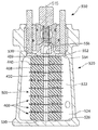
도 2는 도 1의 선 Ⅱ-Ⅱ에 따른 드래프트 기어 조립체의 단면 정면도;
도 3은 도 1~2의 드래프트 기어 조립체 내에 이용된 드래프트 기어 하우징의 사시도;
도 4는 도 3의 선 Ⅳ-Ⅳ에 따른 드래프트 기어 하우징의 단면 정면도;
도 5는 도 3의 선 Ⅴ-Ⅴ에 따른 드래프트 기어 하우징의 단면 평면도;
도 6은 도 3~4의 하우징의 저벽(bottom wall)에 탄성 스프링 스택을 위치시키는 하나의 대안적인 구현예를 특히 도시한 것으로, 도 1~2의 드래프트 기어 조립체의 부분 단면도;
도 7은 도 3~4의 하우징의 저벽에 탄성 스프링 스택을 위치시키는 또 다른 대안적인 구현예를 특히 도시한 것으로, 도 1~2의 드래프트 기어 조립체의 부분 단면도;
도 8은 탄성 스프링 스택의 한 쌍의 말단 판상부재(terminal plate shaped member)를 특히 도시한 것으로, 도 2의 드래프트 기어 조립체의 단면 정면도;
도 9는 종래의 요크와 결합한 도 1~2의 탄성 스프링 스택을 이용한 드래프트 기어 조립체의 단면 정면도;
도 10은 탄성 스프링 스택의 한 쌍의 말단 판상부재를 특히 도시한 것으로, 종래의 요크와 결합한 도 1-2의 탄성 스프링 스택을 이용한 드래프트 기어 조립체의 또 다른 단면 정면도; 및
도 11은 도 1-2의 탄성 스프링 스택 내에 이용되는 탄성 스프링의 단면 정면도이다.1 is a top plan view of a draft gear assembly;
2 is a sectional front view of the draft gear assembly according to line II-II of FIG. 1;
Figure 3 is a perspective view of a draft gear housing used in the draft gear assembly of Figures 1-2;
FIG. 4 is a cross-sectional front view of the draft gear housing according to line IV-IV in FIG. 3; FIG.
5 is a sectional top view of the draft gear housing according to line V-V in Fig. 3;
FIG. 6 is a partial cross-sectional view of the draft gear assembly of FIGS. 1-2, particularly illustrating one alternative embodiment for positioning an elastic spring stack at the bottom wall of the housing of FIGS. 3-4; FIG.
FIG. 7 is a partial cross-sectional view of the draft gear assembly of FIGS. 1-2, particularly illustrating another alternative embodiment for positioning an elastic spring stack in the bottom wall of the housing of FIGS. 3-4; FIG.
Figure 8 is a cross-sectional front view of the draft gear assembly of Figure 2 specifically showing a pair of terminal plate shaped members of an elastic spring stack;
Figure 9 is a cross-sectional front view of a draft gear assembly using the elastic spring stack of Figures 1-2 coupled to a conventional yoke;
10 is a further cross-sectional front view of a draft gear assembly using an elastic spring stack of FIGS. 1-2, particularly illustrating a pair of end plate members of an elastic spring stack, in combination with a conventional yoke; FIG. And
11 is a cross-sectional front view of an elastic spring used in the elastic spring stack of Figs. 1-2.
본 발명의 보다 상세한 설명을 하기 전에, 명확한 이해를 위해 동일한 기능을 하는 동일한 구성요소들은 도면에 도시된 몇몇 도면을 통해 동일한 참조 번호로 식별됨을 주지해야 한다.BRIEF DESCRIPTION OF THE DRAWINGS Before describing the present invention in more detail, it should be noted that identical components having the same function are identified by the same reference numerals throughout the several views shown in the drawings for clarity of understanding.
이제 도 1~7을 참조해보면, 철도차량(나타내지 않음)의 구성과 운행 시 당면하게 되고, 중심축(515)을 따라 드래프트 기어 조립체(510)의 일 단부에 인가되는 버프 및 드래프트 동적 충격력을 완충시키기 위해 종래 이용된 드래프트 기어 조립체(일반적으로 510으로 표시)가 도시되어 있다. 드래프트 기어 조립체(510)는 바람직하게는 강성(rigid)이고 금속으로 제조된 하우징을 포함한다. 일 형태에서, 하우징(일반적으로 520으로 표시)은 중공 내부(522)를 형성하고, 폐쇄부(524) 및 축방향으로 맞은편 개방부(540)를 또한 형성하는, 네 개의 일반적 고형의 측벽(solid side walls)이 있는 종래의 드래프트 기어 하우징으로 일반적으로 제공된다.Referring now to FIGS. 1-7, there is shown a buffer and draft dynamic impact force encountered during construction and operation of a railway vehicle (not shown) and applied to one end of the
드래프트 기어 조립체(510)는 중심축(515)을 따라 하우징(520) 내에 배치된 압축성 탄성 스프링 스택(일반적으로 500으로 표시)을 또한 포함한다. 압축성 탄성 스프링 스택(500)의 상세한 설명은 발명의 명칭 “압축성 탄성 스프링”의 동시계속 미국 특허 출원 제13/233,270호에 개시되어 있고, 번잡을 피하기 위해 이 문서에서는 생략할 것이다.
간단히 말해서, 압축성 탄성 스프링 스택(500)은 서로 일렬로 배치된 복수 개의 압축성 탄성 스프링(400)을 포함한다. 복수 개의 압축성 탄성 스프링(400) 각각은 압축성 탄성 패드(408)와 압축성 탄성 패드(408)의 일 표면과 직접 접촉하도록 포지셔닝된 일 표면이 있는 강성부재(440)를 포함한다. 선택적(optional) 압축성 탄성 패드(409)는 각 말단 탄성 패드의 단부면을 하우징(520)의 폐쇄부(524)의 강성 표면 및 본 문서에서 나중에 기술될 마찰완충장치(friction cushioning mechanism)(550)와 직접 접촉하도록 포지셔닝하기 위하여 압축성 탄성 스프링 스택(500)의 일 말단부(terminal end)에 제공될 수 있다. 제공될 때, 압축성 탄성 패드(409)는 압축성 탄성 스프링 스택(500)의 일 말단부에 배치된 강성부재(440)의 또 다른 표면과 직접 접촉하도록 배치된 일 단부면을 가진다.
특히 도 11을 참조하면, 각각의 압축성 탄성 패드(408, 409)는 일 단부면(416)상에 축방향으로 직립해 있는 실질적 고형의 교대(426)를 포함한다. 본 발명의 바람직한 실시예에서, 실질적 고형의 교대(426)는 중심축(515)에 대해 실질적으로 가로놓인 면에서 일반적으로 둥근 단면을 갖고, 전체에 걸쳐 실질적으로 균일한 두께 및 실질적으로 균일한 직경 각각을 추가로 가진다.
각각의 압축성 탄성 패드(408, 409)는 중심축(515)에 대해 실질적으로 가로놓인 면에서 실질적 고형의 교대(426)의 말단부상에 배치된 주변 립(peripheral lip)(428)을 추가로 포함한다.
축방향 구멍(axial bore)(430)은 전체 압축성 탄성 스프링 스택(500)을 통해 연속적인 구멍을 제공하기 위해서 압축성 탄성 패드(408, 409)의 두께 및 본질적으로 강성부재(440)의 두께를 통해 형성된다.
도 11의 추가적인 참조에서, 강성부재(440)는 최소 하나의 강성부재(440)의 두께를 형성하기 위하여 중심축(515)을 따라 서로 이격되어 있는 한 쌍의 실질적 평면(442 및 444)을 갖는 본질적으로 판상부재이다. 한 쌍의 실질적 평면 중 하나(번호 442로 참조)는 압축성 탄성 패드(408, 409)의 본질적으로 전체 단부면(416)과 직접 접촉하도록 포지셔닝된다. 중심개구(448)는 최소 하나의 강성부재(440)의 두께를 통하여 형성되고, 축방향 교대(426)가 그 안에 효과적으로(operatively) 수용되도록 크기가 설정된다. 여기에서 "효과적으로"라는 용어는 축방향 교대(426)가 중심개구(448)를 통과할 수 있도록 하는 것을 의미하며, 이는 축방향 교대(426)의 말단부가 최소 하나의 강성부재(440)의 한 쌍의 실질적 평면 중 맞은편 평면(번호 444로 참조)을 지나 소정의 거리를 연장하기 위함이다. 더 중요한 것은, 중심개구(448)의 주변 에지(peripheral edge) 주위에 있는 최소 하나의 강성부재(440)의 두께 부분이 도 11에 잘 나타낸 것처럼, 단부면(416) 중 하나와 주변 립(428)의 내면(inner surface) 사이에 케이징된다는 점이다.
최소 하나의 강성부재(440)는 강성부재(440)의 각 표면에 소정의 패턴으로 직립해 있고, 인접한 압축성 탄성 패드(408, 409)의 두께 내에 적어도 부분적으로 배치되는 복수 개의 돌출부(449, 453)를 포함한다.
후술하는 이유로, 각각의 압축성 탄성 패드(408, 409)에 있는 축방향 구멍(430)의 길이 중 최소 15%는 전체에 걸쳐 실질적으로 균일한 직경을 가진다. In short, the compressible
11, each compressible
Each compressible resilient pad 408,409 further includes a
An
11,
The at least one
For reasons discussed below, at least 15% of the length of the
하우징(520)은 압축성 탄성 스프링 스택(500)의 방사상 팽창을 조절하기 위한 수단을 포함한다. 본 발명의 바람직한 일 형태에 있어서, 압축성 탄성 스프링 스택(500)의 방사상 팽창을 조절하기 위한 상기 수단은 압축성 탄성 스프링 스택(500)의 최소 하나의 단부를 로케이팅(locating)하기 위한 수단을 포함한다. 보다 상세하게는, 도 4~5에 잘 나타낸 것처럼, 본 발명의 바람직한 로케이팅 수단은 바람직하게는 환형이고 하우징(520)의 폐쇄부(524)의 일반적으로 평평한 내면(526)상에 축방향으로 배치된 홈(groove)(530)을 포함한다. 환형 홈(annular groove)(530)은 압축성 탄성 패드(408)의 환형 리지(annular ridge), 즉 제1 환형 리지(434)를 수용하기 위해 제공되고, 일반적 직사각형의 단면 형상을 갖는 것이 본 발명에서 바람직하다. 이는 드래프트 기어 조립체(510)의 운행 시 환형 리지(434)의 압축을 수용하기 위함이며, 상기 압축 시 환형 리지(434)는 본질적으로 환형 홈(530)의 부피를 채운다. 상기 일반적 직사각형 단면 형상의 길이는, 환형 리지(434)가 압축 시 평평해지고 본질적으로 환형 홈(530)의 부피를 채울 때, 중심축(515)에 대하여 방사상의 방향으로 탄성 재료의 크기를 증가시키기 위하여 내면(526)과 일반적으로 평행하게 정렬된다.The
또 다른 형태에 있어서, 압축성 탄성 스프링 스택(500)의 방사상 팽창을 조절하기 위한 수단은 드래프트 기어 하우징(520)의 최소 한 쌍의 측벽(도 5에 잘 나타낸 번호 532와 534로 참조)을 포함할 수 있고, 각각의 측벽은 강성부재(440)의 주변에지(peripheral edge)로부터 소정의 공칭(nominal) 거리에 배치된 내부 만곡면(inner curved surface)을 가지고 있다. 각각의 측벽(532, 534)은 측벽(532, 534)의 사용가능한 표면적을 증가시키기 위하여 한 쌍의 선택적 확장부분(535)을 포함할 수 있다.In yet another form, the means for regulating the radial expansion of the
또 다른 형태에 있어서, 도 6에 나타낸 것처럼, 압축성 탄성 스프링 스택(500)의 방사상 팽창을 조절하기 위한 수단은, 폐쇄부(524)의 내면(526)상에 직립해 있고 일반적으로 홈(530)의 위치에 제공되는 또 다른 리지, 즉 제2 환형 리지(536)를 포함할 수 있다. 리지(536)는 조립 후에 압축성 탄성 패드의 환형 홈(434)을 둘러싸도록 크기가 설정된다.6, the means for regulating the radial expansion of the compressible
또 다른 형태에 있어서, 도 7에 나타낸 것처럼, 압축성 탄성 스프링 스택(500)의 방사상 팽창을 조절하기 위한 수단은, 폐쇄부(524)의 내면(526) 안에 배치되어 있고 환형 리지(434)가 거기에 끼어지도록(fit) 크기가 설정되어 있는 리세스(recess)(538)를 포함한다. 리세스(538)의 주변벽(peripheral wall)(539)은 압축성 탄성 스프링 스택(500)의 방사상 이동을 저지한다.7, the means for regulating the radial expansion of the
도 1~2를 더 참조해보면, 하우징(520)의 개방부(540)는 마찰완충장치(일반적으로 550으로 표시)를 수용하도록 개조(adapted)된다. 상기 마찰완충장치(550)는, 예를 들어 발명의 명칭 “하우징을 갖는 탄성 드래프트 기어”의 미국 특허 출원 제12/150,927호에 개시되고 본 발명에서 참조로 인용된 임의의 종래 타입일 수 있다. 그러므로 마찰완충장치(550)의 상세한 설명은 번잡을 피하기 위해 본 문서에서는 생략할 것이다.With further reference to Figures 1-2, the
마찰완충장치(550)는 마찰완충장치(550)의 일반적으로 평평한 내부 단부면(554)상에 압축성 탄성 스프링 스택(500)의 맞은편 단부를 로케이팅하기 위한 수단이 더 제공된다. 상기 내부 단부면(554)은 스프링시트(spring seat)(552)에 또한 제공된다. 내부 단부면(554)상에 압축성 탄성 스프링 스택(500)의 일 단부를 로케이팅하기 위한 수단은 바람직하게는 또 다른 환형 홈(530)을 포함하지만 상기 기술된 리지(536) 또는 리세스(538)를 포함할 수도 있다.The
이제 도 8을 참조해보면, 드래프트 기어 조립체(510)와 본질적으로 동일하게 구성되어 있고, 스프링 스택(502)의 이용 외에 한 쌍의 말단 강성 판상부재(terminal rigid plate shaped member)(441)가 있는 드래프트 기어 조립체(일반적으로 511로 표시)가 도시되어 있다. 말단 강성 판상부재(441)는 스프링 스택의 방사상 이동을 제거까지는 아니라도 적어도 저지는 하기 위해 각각의 표면(526과 554)상에 포지셔닝될 수 있다. 예를 들어, 각각의 판(441)은 상기 기술된 리세스(538) 내에 배치될 수 있다. 또는 말단 강성 판상부재(441)는 본 문서에 참조로 인용된 상기 출원의 교시에 따라 포지셔닝될 수 있다.Referring now to FIG. 8, a draft having a terminal rigid plate shaped
본 발명은 또한 압축성 탄성 스프링 스택(500)이 단지 하나의 말단 강성 판상 부재로 제공될 수 있고, 여기서 스프링 스택(500)은 서로 일렬로 배치된 압축성 탄성 스프링(400)으로만 구성될 수 있다.The present invention also contemplates that the compressible
도 9에 나타낸 또 다른 형태에서, 드래프트 기어 조립체(일반적으로 512로 표시)는 하우징(일반적으로 560으로 지정), 커플러 샹크(coupler shank)(나타내지 않음)의 단부에 연결하도록 개조된 요크 단부(yoke end)(562), 축방향으로 요크 단부(562) 맞은편에 있는 버트 단부(butt end)(564), 한 쌍의 이격된(spaced-apart) 세장형(elongated)의 상부 및 하부 스트랩부재(strap member)(각각 566 및 568)를 포함한다. 각각의 상부 및 하부 스트랩부재는 내면, 외면, 전단부(front end) 및 후단부(rear end)를 가지고 있고, 각 스트랩부재(566, 568)의 후단부는 하우징(560)의 버트 단부(564)에 결합되어 있고, 각 스트랩부재(566, 568)의 전단부는 하우징(560)의 요크 단부(562)에 결합되어 있다. 또한 종래 방식에 있어서, 도 9의 드래프트 기어 조립체(512)는 드래프트 기어 조립체(510)가 철도차량(나타내지 않음)상에 설치될 때, 압축성 탄성 스프링 스택(500)의 앞쪽에 포지셔닝된 커플러 팔로워(coupler follower)(570)와 압축성 탄성 스프링 스택(500)의 뒤쪽에 포지셔닝된 후방 팔로워(rear follower)(572)를 더 포함한다. 각 팔로워(570, 572)는 환형 홈(530)을 포함하는 것으로 나타나있다. 또한, 전방 팔로워(570)에는 축방향 관통개구(through aperture)(574)가 있는 반면, 후방 팔로워(572)는 축방향 구멍(528)을 포함한다.9, the draft gear assembly (generally indicated at 512) includes a housing (designated generally as 560), a yoke end adapted to connect to the end of a coupler shank (not shown) a
마지막으로, 도 10은 본질적으로 드래프트 기어 조립체(513)로 구성되어 있고, 스프링 스택(502)이 스프링 스택(500)을 대체하는 것 외에도 추가적인 저지 요소들(restraining elements)이 팔로워(570과 572)의 안쪽에 배치된 표면 내에 포함되어 있는 드래프트 기어 조립체(일반적으로 513으로 지정)를 도시한다.Finally, Figure 10 essentially consists of
패드(408과 409)의 구성과 이 패드들이 강성부재(440, 441)와 기계적으로 인터록킹(interlocking)된 방식은 본 발명에서 드래프트 기어 조립체(510)의 바람직한 제조 방법을 제공하며, 그 제조 방법은 폐쇄부(524)와 축방향으로 맞은편에 개방부(540)가 있는 중공 하우징(520)을 제공하는 단계를 포함한다. 다음으로, 제조 방법은 복수 개의 압축성 탄성 스프링(400)을 제공하는 단계를 포함하며, 복수 개의 압축성 탄성 스프링(440) 각각은 축방향으로 강성부재(440)에 고정된 압축성 탄성 패드(408)를 포함하고 압축성 탄성 패드(408)의 두께 및 본질적으로 강성부재(440)의 두께를 통해 형성된 축방향 구멍(430)을 가진다. 다음으로, 복수개의 압축성 탄성 스프링(400)은 드래프트 기어 조립체(510)의 종축(515)을 따라 축방향 및 일렬로 개방부(540)를 통해 중공 하우징(520) 안으로 스태킹된다. 스태킹 중에, 각각의 압축성 탄성 스프링(400)의 압축성 탄성 패드(408)의 단부면은 인접해있는 강성부재(440)의 표면과 직접 접촉하도록 배치된다. 이 후, 제조 방법은 또 다른 압축성 탄성 패드(409)를 말단 강성부재(440)의 표면상에 포지셔닝하는 선택적인 단계를 포함할 수 있고, 상기 또 다른 압축성 탄성 패드(409)는 그 두께를 통해 형성된 축방향 구멍(430)을 가진다. 그 다음으로, 비록 본 발명은 압축성 탄성 스택(500)의 조립 중에 측벽(532, 534)의 내면이 포지셔닝 가이드(positioning guide)로서 이용될 수 있는 것을 고려하지만, 세장형 강성부재(나타내지 않음)가 복수 개의 압축성 탄성 스프링(400) 각각의 축방향 구멍(430) 및 제공될 경우 선택적인 압축성 탄성 패드(409)의 구멍을 통해 삽입된다. 상기 세장형 강성부재(나타내지 않음)의 단부를 수용하기 위해, 중심 구멍(528)이 하우징(520)의 폐쇄부(524)의 내면(526) 안에 제공된다. 마지막으로, 복수 개의 압축성 탄성 스프링(400) 및 선택적인 압축성 탄성 패드(409)는 강성부재(440)와 기계적으로 인터록킹하기 위하여 드래프트 기어 조립체(510)의 종축(515)을 따라 압축된다.The configuration of the
압축성 탄성 스프링 스택의 압축은 스태킹으로 생성된(resulting) 압축성 탄성 스택의 외부 단부(outer end)에 일시적인 축방향 힘을 인가함으로서 달성될 수 있다.Compression of the compressible resilient spring stack can be achieved by applying a transient axial force to the outer end of the resulting compressible resilient stack.
바람직하게는, 제조 방법은 복수 개의 압축성 탄성 스프링(400) 및 압축성 탄성 패드(409)를 압축하기 전에, 마찰완충장치(550)의 시트(552)가 일 단부 압축성 탄성 패드(도 2에서 압축성 탄성 패드(409)로 나타냄)의 외부 단부면과 직접 접촉하도록 포지셔닝을 제공한다. 상기 구현예에서 축방향 힘은 스프링 시트(552)의 맞은편 단부에 인가된다.Preferably, the manufacturing method is such that the
제조 방법은 마찰완충장치(550)의 시트(552)에 축방향의 관통구멍(through bore)(556)을 제공하는 추가적인 단계, 축방향 구멍(556)을 통해 세장형 강성부재(나타내지 않음)를 삽입하는 단계 및 단부들 사이의 축방향 구멍(556) 내에 세장형 강성부재의 일 단부를 포지셔닝하는 단계를 또한 포함한다. 제조 방법은 복수 개의 스프링(400)과 제공될 경우 선택적인 말단 탄성 패드(409)를 압축한 후 세장형 강성부재(나타내지 않음)의 제거를 고려한다.The manufacturing method is further characterized by providing an additional step of providing an axial through
복수 개의 스프링(400)을 스태킹하는 단계는, 예를 들어 하우징(520)의 폐쇄부(524)의 내면(526)과 같은 내부면(interior surface)과 말단에 위치한 압축성 탄성 패드(408)의 최소 일 단부를 직접 접촉하도록 포지셔닝하는 방법에 의해, 하우징(520)의 폐쇄부(524)의 내면(526)상에 말단 압축성 탄성 패드(408)의 일 단부를 로케이팅하기 위한 수단을 제공하는 단계를 포함한다. The step of stacking the plurality of
제조 방법은 또한 중공 하우징(520)의 측벽을 통해 형성된, 압축된 스프링 스택(500)의 길이를 초과하여 내부면(526)으로부터 거리를 두고 배치된 개구(542)를 통해 삽입된 종래의 핀들(나타내지 않음)에 의해 소정의 압축된 높이로 복수 개의 압축성 탄성 스프링 스택(500)을 유지하는 추가적인 단계를 고려한다. 스프링 스택(500)이 압축되고 세장형 강성부재(나타내지 않음)가 제거된 후, 마찰완충장치(550)는 종래 방식으로 중공 하우징(520)의 개방부(540) 안으로 설치된다.The manufacturing method also includes forming a plurality of conventional pins (not shown) inserted through
전체에 걸쳐 적어도 15%의 실질적으로 균일한 직경을 가진 중심구멍(430)을 제공하는 중요성은, 상기 중심구멍(430)이 축방향 힘의 인가 전 드래프트 기어 하우징(520) 내에 인접한 강성부재(440)가 있는 모든 압축성 탄성 패드(408, 409)를 센터링(centering) 하기에 충분한 세장형 강성부재(나타내지 않음)를 위한 가이던스(guidance)를 제공한다는 점이다.The significance of providing a
상기 기술된 방법은 도 8의 스프링 스택(502)을 설치하는 데에 실질적으로 적용할 수 있고, 각각의 드래프트 기어 조립체(512, 513) 내에 스프링 스택(500, 502)을 설치하는 데에도 또한 적용할 수 있다.The method described above is substantially applicable to installing the
최소 하나의 스프링 스택(500)은 본 문서에 참조로 인용된, 발명의 명칭 “결합 요크 및 탄성 드래프트 기어”의 미국 특허 출원 제12/150,777호 및 발명의 명칭 “결합 요크 및 마찰 장치를 갖는 탄성 드래프트 기어”의 미국 특허 출원 12/150,808호에 교시된 드래프트 기어 타입에서 이용될 수 있는 것이고, 그와 같이 상호 참조된 관련 출원들의 다양한 교시는 본 발명에서 이용될 수 있는 것으로 당업자는 또한 이해할 것이다. At least one
이와 같이, 본 발명은 당업자가 동일한 것을 제작하고 사용하기에 적합하도록 충분하고, 명확하고, 간결하고 정확한 용어들로 기술되었다. 상세하게 기술된 본 발명의 구현예의 구성 요소들의 변화, 변형, 등가물과 대체물은 첨부된 청구항에 기술된 바와 같은 본 발명의 개념과 범위로부터 벗어나지 않고 당업자에 의해 실시될 수 있는 것으로 이해할 것이다. As such, the present invention has been described in sufficient, clear, concise, and precise terms to enable those skilled in the art to make and use the same. It will be understood that variations, modifications, equivalents and alternatives of the components of the embodiments of the invention described in detail can be practiced by those skilled in the art without departing from the concept and scope of the invention as set forth in the appended claims.
Claims (44)
(a) 하우징; 및
(b) 상기 중심축을 따라 상기 하우징 내에 배치되고, 서로 일렬로 배치된 복수 개의 압축성 탄성 스프링을 포함하며, 상기 복수 개의 압축성 탄성 스프링 각각은 하기를 포함하는 것을 특징으로 하는 압축성 탄성 스프링 스택:
상기 복수 개의 압축성 탄성 스프링 각각은,
i. 압축성 탄성 패드,
ii. 상기 압축성 탄성 패드의 일 단부면과 직접 접촉하도록 포지셔닝된 일 표면이 있는 강성부재로서, 상기 강성부재의 두께를 통해 형성된 중심개구를 더 가지며, 상기 두께는 상기 중심축을 따라 상기 강성부재의 상기 일 표면으로부터 이격된 또 다른 표면에 의해 형성되고, 상기 일 표면과 상기 또 다른 표면은 상기 중심축에 수직으로 배치되는 평면인 상기 강성부재,
iii. 상기 압축성 탄성 패드의 상기 일 단부면상에 축방향으로 직립해 있는 교대로서, 상기 강성부재의 두께를 통해 형성된 상기 중심개구 내에 수용되도록 크기가 설정된 주변면이 있는 상기 교대, 및
iv. 상기 중심축에 대해 가로놓인 면에서 상기 축방향 교대의 말단부상에 배치된 환형 립을 포함하며,
상기 강성부재의 환형 두께 부분은 상기 압축성 탄성 패드의 상기 일 단부면과 상기 환형 립의 내면 사이에 케이징되는 것을 특징으로 하는 드래프트 기어 조립체.
In order to cushion the buck and draft dynamic impact forces encountered in the construction and operation of the railway vehicle and applied to the draft gear assembly along the central axis, the draft gear assembly comprising:
(a) a housing; And
(b) a plurality of compressible resilient springs disposed in the housing along the central axis and arranged in a line with each other, wherein each of the plurality of compressible resilient springs comprises:
Wherein each of the plurality of compressible elastic springs comprises:
i. Compressible elastic pad,
ii. A rigid member having a surface positioned to be in direct contact with an end surface of the compressible resilient pad, the rigid member further having a central opening formed through the thickness of the rigid member, Wherein said one surface and said another surface are planes disposed perpendicular to said central axis,
iii. Wherein said alternating, with said peripheral surface being sized to be received within said central opening formed through the thickness of said rigid member, alternating in an axial upright position on said one end face of said compressible elastic pad;
iv. And an annular lip disposed on said axially alternating end in a plane transverse to said central axis,
Wherein an annular thickness portion of the rigid member is spaced between the one end surface of the compressible resilient pad and the inner surface of the annular lip.
상기 압축성 탄성 스프링 스택의 일 단부에 배치된 말단 강성부재의 또 다른 표면과 직접 접촉하도록 포지셔닝된 일 단부면이 있는 또 다른 압축성 탄성 패드를 더 포함하는 것을 특징으로 하는 드래프트 기어 조립체.
The method according to claim 1,
Further comprising another compressible resilient pad having an end surface positioned to be in direct contact with another surface of the distal rigid member disposed at one end of the compressible spring stack.
상기 압축성 탄성 패드의 두께와 상기 교대의 두께를 통해 형성된 축방향 구멍을 더 포함하는 것을 특징으로 하는 드래프트 기어 조립체.
The method according to claim 1,
Further comprising an axial hole formed through the thickness of the compressible resilient pad and the alternating thickness. ≪ Desc / Clms Page number 13 >
상기 축방향 구멍의 길이의 적어도 15%는 전체에 걸쳐 균일한 직경을 갖는 것을 특징으로 하는 드래프트 기어 조립체.
The method of claim 3,
Wherein at least 15% of the length of the axial bore has a uniform diameter throughout.
상기 하우징은 강성이고, 폐쇄부, 축방향으로 맞은편의 개방부 및 상기 강성 하우징의 중공 내부를 형성하는 네 개의 고형의 측벽을 포함하는 것을 특징으로 하는 드래프트 기어 조립체.
The method according to claim 1,
Wherein the housing is rigid and comprises a closed portion, an axially opposed opening, and four solid side walls defining a hollow interior of the rigid housing.
상기 하우징은 상기 압축성 탄성 스프링 스택의 방사상 팽창을 조절하기 위한 수단을 포함하는 것을 특징으로 하는 드래프트 기어 조립체.6. The method of claim 5,
Wherein said housing comprises means for regulating the radial expansion of said compressible resilient spring stack.
상기 압축성 탄성 스프링 스택의 방사상 팽창을 조절하기 위한 수단은, 말단 압축성 탄성 패드의 단부면 상에 배치된 환형 리지 및 상기 하우징의 폐쇄부의 내면 안의 리세스를 포함하며, 상기 리세스는 상기 환형 리지가 상기 리세스 내에 수용되도록 크기가 설정되고, 상기 리세스의 주변벽은 상기 압축성 탄성 스프링 스택의 방사상 이동을 저지하는 것을 특징으로 하는 드래프트 기어 조립체.
The method according to claim 6,
Wherein the means for regulating the radial expansion of the compressible spring stack comprises an annular ridge disposed on an end face of the distal compressible resilient pad and a recess in an interior surface of the enclosure of the housing, And a peripheral wall of the recess prevents radial movement of the compressible spring stack. ≪ Desc / Clms Page number 20 >
상기 압축성 탄성 스프링 스택의 방사상 팽창을 조절하기 위한 수단은, 상기 강성부재의 주변에지로부터 소정의 공칭 거리에 배치된 내부 만곡면을 갖는 상기 하우징의 한 쌍의 측벽을 포함하는 것을 특징으로 하는 드래프트 기어 조립체.
The method according to claim 6,
Wherein the means for adjusting the radial expansion of the compressible spring stack comprises a pair of sidewalls of the housing having an inner curved surface disposed at a predetermined nominal distance from a peripheral edge of the rigid member. Assembly.
상기 압축성 탄성 스프링 스택의 방사상 팽창을 조절하기 위한 수단은, 상기 압축성 탄성 스프링 스택의 최소 하나의 단부를 로케이팅하기 위한 수단을 포함하는 것을 특징으로 하는 드래프트 기어 조립체.
The method according to claim 6,
Wherein the means for regulating the radial expansion of the compressible resilient spring stack comprises means for locating at least one end of the compressible resilient spring stack.
상기 로케이팅 수단은 상기 하우징의 폐쇄부의 내벽면 상에 축방향으로 배치된 환형 홈을 포함하는 것을 특징으로 하는 드래프트 기어 조립체.
10. The method of claim 9,
Wherein the locating means comprises an annular groove axially disposed on the inner wall surface of the closed portion of the housing.
상기 환형 홈은 직사각형의 단면 형상을 갖는 것을 특징으로 하는 드래프트 기어 조립체.
11. The method of claim 10,
Wherein the annular groove has a rectangular cross-sectional shape.
상기 압축성 탄성 스프링 스택의 방사상 팽창을 조절하기 위한 수단은, 상기 강성부재의 주변에지로부터 소정의 공칭 거리에 배치된 내면을 갖는 상기 하우징의 최소 한 쌍의 측벽을 포함하는 것을 특징으로 하는 드래프트 기어 조립체.
The method according to claim 6,
Wherein the means for regulating the radial expansion of the compressible spring stack comprises at least a pair of side walls of the housing having an inner surface disposed at a predetermined nominal distance from a peripheral edge of the rigid member. .
상기 압축성 탄성 스프링 스택의 방사상 팽창을 조절하기 위한 수단은, 상기 하우징의 폐쇄부의 내벽면 상에 배치된 환형 리지를 포함하고, 상기 폐쇄부의 내벽면은 상기 하우징의 상기 중심축에 대해 수직으로 포지셔닝된 것을 특징으로 하는 드래프트 기어 조립체.
The method according to claim 6,
Wherein the means for regulating the radial expansion of the compressible resilient spring stack comprises an annular ridge disposed on the inner wall surface of the closed portion of the housing and the inner wall surface of the closed portion is positioned perpendicular to the central axis of the housing Of the draft gear assembly.
하나의 말단 압축성 탄성 패드의 단부는 상기 하우징의 폐쇄부의 내벽면과 직접적으로 인접하여 포지셔닝된 것을 특징으로 하는 드래프트 기어 조립체.
14. The method of claim 13,
Wherein an end of the one end compressible elastic pad is positioned directly adjacent to the inner wall surface of the closed portion of the housing.
최소 하나의 말단 압축성 탄성 패드의 단부면 상에 배치된 환형 리지를 더 포함하는 것을 특징으로 하는 드래프트 기어 조립체.
15. The method of claim 14,
Further comprising an annular ridge disposed on an end face of the at least one distal compressible resilient pad.
적어도 상기 개방부 내에 배치된 마찰완충장치 및 상기 마찰완충장치의 내부 단부면 상에 상기 압축성 탄성 스프링 스택의 일 단부를 로케이팅하기 위한 수단을 더 포함하는 것을 특징으로 하는 드래프트 기어 조립체.
6. The method of claim 5,
Further comprising a friction damping device disposed in at least said opening and means for locating one end of said compressible spring stack on an inner end face of said friction dampening device.
상기 하우징은,
커플러 샹크의 단부에 연결되도록 개조된 요크 단부,
축방향으로 상기 요크 단부의 맞은편에 있는 버트 단부,
평행하게 이격된 한 쌍의 세장형의 상부 스트랩부재 및 하부 스트랩부재로서, 상기 상부 스트랩부재 및 하부 스트랩부재 각각은 내면, 외면, 전단부 및 후단부를 가지고, 각 스트랩부재의 후단부는 상기 하우징의 버트 단부에 결합되고, 각 스트랩부재의 전단부는 상기 하우징의 요크 단부에 결합되는, 상기 상부 스트랩부재 및 하부 스트랩부재를 포함하는 것을 특징으로 하는 드래프트 기어 조립체.
The method according to claim 1,
The housing includes:
A yoke end adapted to be connected to the end of the coupler shank,
A butt end opposite the yoke end in the axial direction,
Each of said upper and lower strap members having an inner surface, an outer surface, a front end portion and a rear end portion, and a rear end portion of each strap member is connected to a butt of said housing, And the front end of each strap member is coupled to the yoke end of the housing, wherein the upper strap member and the lower strap member are coupled to each other.
상기 드래프트 기어 조립체가 상기 철도차량에 설치될 때, 상기 압축성 탄성 스프링 스택의 앞쪽에 포지셔닝되는 커플러 팔로워 및 상기 압축성 탄성 스프링 스택의 뒤쪽에 포지셔닝되는 후방 팔로워를 더 포함하는 것을 특징으로 하는 드래프트 기어 조립체.
18. The method of claim 17,
Further comprising a coupler follower positioned in front of the compressible spring stack when the draft gear assembly is installed in the railway vehicle and a rear follower positioned in the rear of the compressible spring stack.
상기 커플러 팔로워의 두께를 통해 형성된 중심 관통구멍을 더 포함하는 것을 특징으로 하는 드래프트 기어 조립체.
19. The method of claim 18,
And a center through hole formed through the thickness of the coupler follower.
상기 커플러 팔로워 및 상기 후방 팔로워 각각의 내부면에 형성된 환형 홈을 더 포함하는 것을 특징으로 하는 드래프트 기어 조립체.
19. The method of claim 18,
Further comprising an annular groove formed in an inner surface of each of said coupler follower and said rear follower.
상기 강성부재의 각 표면에 소정의 패턴으로 직립해 있고, 인접한 압축성 탄성 패드의 두께 내에 적어도 부분적으로 배치되는 복수 개의 돌출부를 더 포함하는 것을 특징으로 하는 드래프트 기어 조립체.
The method according to claim 1,
Further comprising a plurality of protrusions erected on each surface of the rigid member in a predetermined pattern and disposed at least partially within the thickness of the adjacent compressible resilient pad.
말단 압축성 탄성 패드의 노출된 단부면에 기계적으로 고정되는 추가적인 강성부재를 더 포함하는 것을 특징으로 하는 드래프트 기어 조립체.
The method according to claim 1,
Further comprising an additional rigid member mechanically secured to the exposed end surface of the distal compressible resilient pad. ≪ RTI ID = 0.0 > 11. < / RTI >
(a) 폐쇄부 및 축방향으로 맞은편에 개방부가 있는 하우징을 제공하는 단계;
(b) 복수 개의 압축성 탄성 스프링 각각은 일 단부면상에 축방향으로 직립해 있는 교대를 갖는 압축성 탄성 패드를 포함하고, 상기 교대는 중심축에 대해 가로놓인 면에서 상기 교대의 말단부상에 배치된 환형 립을 포함하며, 상기 압축성 탄성 패드는 강성부재에 축방향으로 고정되고 상기 압축성 탄성 패드의 두께 및 상기 강성부재의 두께를 통해 형성된 축방향 관통구멍을 가지고 있는, 복수 개의 압축성 탄성 스프링을 제공하는 단계;
(c) 상기 드래프트 기어 조립체의 종축을 따라 축방향으로 상기 복수 개의 압축성 탄성 스프링을 중공 하우징 안으로 스태킹하는 단계; 및
(d) 상기 교대가 상기 강성부재의 축방향 관통구멍 내에 수용되도록, 상기 드래프트 기어 조립체의 종축을 따라 상기 복수 개의 압축성 탄성 스프링을 압축함으로써, 상기 강성부재의 환형 두께 부분이 상기 압축성 탄성 패드의 일 단부면과 상기 환형 립의 내면 사이에 케이징되고, 상기 립의 외면이 상기 강성부재의 또 다른 면 위로 연장되는 단계를 포함하는 것을 특징으로 하는 드래프트 기어 조립체의 조립 방법.
A method of assembling a draft gear assembly, comprising the steps of:
(a) providing a housing having a closure and an axially opposed opening;
(b) each of the plurality of compressible resilient springs includes a compressible resilient pad having an alternating upstanding axial direction on one end surface, the alternating annular ring having an annular shape disposed on the alternate end in a plane transverse to the central axis Wherein the compressible resilient pad is axially secured to the rigid member and has an axial through hole formed through the thickness of the compressible resilient pad and the thickness of the rigid member, ;
(c) stacking the plurality of compressible resilient springs axially along the longitudinal axis of the draft gear assembly into the hollow housing; And
(d) compressing the plurality of compressible resilient springs along a longitudinal axis of the draft gear assembly such that the alternation is received within an axial through hole of the rigid member, wherein an annular thick portion of the rigid member And wherein an outer surface of the lip extends over another surface of the rigid member. ≪ RTI ID = 0.0 > 11. < / RTI >
단계 (c)에서 스태킹 후, 상기 복수 개의 압축성 탄성 스프링 각각의 상기 축방향 관통구멍을 통해 세장형 강성부재를 삽입하는 단계를 더 포함하는 것을 특징으로 하는 드래프트 기어 조립체의 조립 방법.
24. The method of claim 23,
Further comprising inserting a elongated rigid member through the axial through holes of each of the plurality of compressible elastic springs after stacking in step (c). ≪ Desc / Clms Page number 20 >
상기 하우징의 상기 폐쇄부의 내면에 축방향 구멍을 제공하는 단계 및 상기 축방향 구멍 내에 상기 세장형 강성부재의 일 단부를 포지셔닝하는 단계를 더 포함하는 것을 특징으로 하는 드래프트 기어 조립체의 조립 방법.
25. The method of claim 24,
Further comprising the steps of providing an axial bore in an inner surface of said closed portion of said housing and positioning one end of said elongated rigid member within said axial bore.
단계 (d)에서 상기 복수 개의 압축성 탄성 스프링을 압축한 후, 상기 세장형 강성부재를 제거하는 추가적인 단계를 더 포함하는 것을 특징으로 하는 드래프트 기어 조립체의 조립 방법.
25. The method of claim 24,
Further comprising compressing the plurality of compressible elastic springs in step (d), and then removing the elongated rigid member.
또 다른 압축성 탄성 패드의 두께를 통해 형성된 축방향 구멍을 갖는 상기 또 다른 압축성 탄성 패드를 말단 강성부재의 표면에 포지셔닝하는 단계를 포함하는 드래프트 기어 조립체의 조립 방법.
24. The method of claim 23,
Positioning said another compressible resilient pad having an axial hole formed through the thickness of another compressible resilient pad on a surface of said rigid member. ≪ Desc / Clms Page number 17 >
상기 압축하는 단계는, 얻어진 압축성 탄성 스택의 말단 압축성 탄성 패드의 외부 단부에 일시적인 축방향 힘을 인가하는 단계를 포함하는 것을 특징으로 하는 드래프트 기어 조립체의 조립 방법.
24. The method of claim 23,
Wherein said compressing step comprises applying a temporary axial force to the outer end of the resulting compressible, resilient, end-compressible elastic pad of the resulting compressible elastic stack.
단계 (c)에서 상기 복수 개의 압축성 탄성 스프링을 스태킹한 후, 말단 탄성 스프링에 마찰완충장치의 시트를 포지셔닝하는 단계를 포함하는 것을 특징으로 하는 드래프트 기어 조립체의 조립 방법.
24. The method of claim 23,
Further comprising the step of stacking the plurality of compressible resilient springs in step (c) and then positioning the seat of the friction dampening device on the distal resilient springs.
상기 마찰완충장치의 상기 시트에 축방향 구멍을 제공하는 단계,
상기 축방향 구멍을 통해 세장형 강성부재를 삽입하는 단계, 및
상기 축방향 구멍 내에 상기 세장형 강성부재의 일 단부를 배치하는 단계를 더 포함하는 것을 특징으로 하는 드래프트 기어 조립체의 조립 방법.
30. The method of claim 29,
Providing an axial hole in the seat of the friction damping device,
Inserting a elongated rigid member through said axial bore, and
Further comprising the step of disposing one end of the elongated rigid member in the axial hole.
상기 복수 개의 압축성 탄성 스프링을 스태킹하는 단계는, 말단 압축성 탄성 패드의 일 단부를 상기 하우징의 폐쇄부의 내벽면과 직접 접촉하도록 포지셔닝하는 단계를 포함하는 것을 특징으로 하는 드래프트 기어 조립체의 조립 방법.
24. The method of claim 23,
Wherein the step of stacking the plurality of compressible resilient springs comprises positioning one end of the distal compressible resilient pad to be in direct contact with the inner wall surface of the enclosure of the housing.
상기 하우징의 폐쇄부의 내벽면상에 상기 말단 압축성 탄성 패드의 상기 일단부를 로케이팅하기 위한 수단을 제공하는 추가적인 단계를 더 포함하는 것을 특징으로 하는 드래프트 기어 조립체의 조립 방법.
32. The method of claim 31,
Further comprising the additional step of providing means for locating said one end of said end compressible elastic pad on an inner wall surface of a closed portion of said housing.
상기 복수 개의 압축성 탄성 스프링을 소정의 압축된 높이로 유지하는 추가적인 단계를 더 포함하는 것을 특징으로 하는 드래프트 기어 조립체의 조립 방법.
24. The method of claim 23,
Further comprising the additional step of maintaining said plurality of compressible resilient springs at a predetermined compressed height. ≪ Desc / Clms Page number 20 >
상기 하우징의 개방부에 마찰완충장치를 포지셔닝하는 추가적인 단계를 더 포함하는 것을 특징으로 하는 드래프트 기어 조립체의 조립 방법.
34. The method of claim 33,
Further comprising the additional step of positioning the friction dampening device in the opening of the housing.
각 강성부재의 각 표면상에 복수 개의 돌출부를 제공하는 단계를 더 포함하는 것을 특징으로 하는 드래프트 기어 조립체의 조립 방법.
24. The method of claim 23,
Further comprising providing a plurality of projections on each surface of each rigid member.
(a) 개방부 및 축방향으로 맞은편에 폐쇄부가 있는 하우징;
(b) 상기 중심축을 따라 상기 하우징 내에 배치되고, 서로 일렬로 배치된 복수 개의 압축성 탄성 스프링을 포함하며, 상기 복수 개의 압축성 탄성 스프링 각각은 일 표면에 강성부재가 면 접촉으로 부착되는 압축성 탄성 패드를 포함하는 압축성 탄성 스프링 스택;
(c) 상기 하우징의 상기 중심축과 중심이 같고, 상기 하우징의 폐쇄부의 내벽면에 제공되는 환형 홈; 및
(d) 상기 하우징의 상기 중심축과 중심이 같고, 말단 압축성 탄성 패드의 단부면상에 직립해 있는 환형 리지를 포함하며,
상기 환형 리지는 상기 환형 홈 내에 수용되도록 크기가 설정되고, 상기 말단 압축성 탄성 패드의 단부면은 상기 하우징의 폐쇄부의 내벽면과 직접적으로 인접하여 포지셔닝된 것을 특징으로 하는 드래프트 기어 조립체.
In order to cushion the buck and draft dynamic impact forces encountered in the construction and operation of the railway vehicle and applied to the draft gear assembly along the central axis, the draft gear assembly comprising:
(a) a housing having an opening and an axially opposite closing portion;
(b) a plurality of compressible resilient springs disposed in the housing along the central axis and arranged in a line, wherein each of the plurality of compressible resilient springs comprises a compressible resilient pad having a rigid member in surface contact on one surface thereof A compressible resilient spring stack;
(c) an annular groove concentric with the central axis of the housing and provided on an inner wall surface of a closed portion of the housing; And
(d) an annular ridge centered on the central axis of the housing and standing on the end face of the end compressible elastic pad,
Wherein said annular ridge is sized to be received within said annular groove and said end compressible elastic pad end surface is positioned directly adjacent to an inner wall surface of a closed portion of said housing.
(a) 적어도 상기 하우징의 개방부 내에 배치된 마찰완충장치;
(b) 상기 하우징의 상기 중심축과 중심이 같고, 상기 마찰완충장치의 일 표면에 제공되는 또 다른 환형 홈; 및
(c) 상기 하우징의 상기 중심축과 중심이 같고, 축방향으로 맞은편에 있는 말단 압축성 탄성 패드의 단부면 상에 직립해 있는 또 다른 환형 리지를 더 포함하며,
상기 또 다른 환형 리지는 상기 또 다른 환형 홈 내에 수용되도록 크기가 설정되고, 상기 또 다른 말단 압축성 탄성 패드의 단부면은 상기 마찰완충장치의 상기 일 표면과 직접적으로 인접하여 포지셔닝되는 것을 특징으로 하는 드래프트 기어 조립체.
37. The method of claim 36,
(a) a friction damping device disposed within at least an opening of the housing;
(b) another annular groove concentric with the central axis of the housing and provided on one surface of the friction damping device; And
(c) a further annular ridge centered on the end surface of the compressible, end-pressing elastic pad, axially opposite the central axis of the housing,
Wherein said another annular ridge is sized to be received within said another annular groove and the end surface of said another end compressible elastic pad is positioned directly adjacent to said one surface of said friction damping device. Gear assembly.
(a) 개방부 및 축방향으로 맞은편에 폐쇄부가 있는 하우징;
(b) 상기 중심축을 따라 상기 하우징 내에 배치되고, 서로 일렬로 배치된 복수 개의 압축성 탄성 스프링을 포함하며, 상기 복수 개의 압축성 탄성 스프링 각각은 일 표면에 강성부재가 면 접촉으로 부착되는 압축성 탄성 패드를 포함하는 압축성 탄성 스프링 스택;
(c) 상기 하우징의 상기 중심축과 중심이 같고, 상기 하우징의 폐쇄부의 내벽면 상에 직립해 있는 제1 환형 리지; 및
(d) 상기 하우징의 상기 중심축과 중심이 같고, 말단 압축성 탄성 패드의 단부면상에 직립해 있는 제2 환형 리지를 포함하며,
상기 제2 환형 리지는 상기 제1 환형 리지 내에 수용되도록 크기가 설정되고, 상기 말단 압축성 탄성 패드의 단부면은 상기 하우징의 폐쇄부의 내벽면과 직접적으로 인접하여 포지셔닝되는 것을 특징으로 하는 드래프트 기어 조립체.
In order to cushion the buck and draft dynamic impact forces encountered in the construction and operation of the railway vehicle and applied to the draft gear assembly along the central axis, the draft gear assembly comprising:
(a) a housing having an opening and an axially opposite closing portion;
(b) a plurality of compressible resilient springs disposed in the housing along the central axis and arranged in a line, wherein each of the plurality of compressible resilient springs comprises a compressible resilient pad having a rigid member in surface contact on one surface thereof A compressible resilient spring stack;
(c) a first annular ridge centered on the central axis of the housing and standing upright on an inner wall surface of a closed portion of the housing; And
(d) a second annular ridge centered on the central axis of the housing and standing on the end face of the distal compressible resilient pad,
Wherein said second annular ridge is sized to be received within said first annular ridge and wherein said end compressible elastic pad end surface is positioned directly adjacent to an inner wall surface of a closed portion of said housing.
(a) 개방부 및 축방향으로 맞은편에 폐쇄부가 있는 하우징;
(b) 상기 중심축을 따라 상기 하우징 내에 배치되고, 서로 일렬로 배치된 복수 개의 압축성 탄성 스프링을 포함하며, 상기 복수 개의 압축성 탄성 스프링 각각은 일 표면에 강성부재가 면 접촉으로 부착되는 압축성 탄성 패드를 포함하는 압축성 탄성 스프링 스택;
(c) 상기 하우징의 상기 중심축과 중심이 같고, 상기 하우징의 폐쇄부의 내벽면에 제공되는 리세스; 및
(d) 상기 하우징의 상기 중심축과 중심이 같고, 말단 압축성 탄성 패드의 단부면상에 직립해 있는 환형 리지를 포함하며,
상기 환형 리지는 상기 리세스 내에 수용되도록 크기가 설정되고, 상기 말단 압축성 탄성 패드의 단부면은 상기 하우징의 폐쇄부의 내벽면과 직접적으로 인접하여 포지셔닝되며, 상기 리세스의 주변벽은 상기 압축성 탄성 스프링 스택의 방사상 이동을 저지하는 것을 특징으로 하는 드래프트 기어 조립체.
In order to cushion the buck and draft dynamic impact forces encountered in the construction and operation of the railway vehicle and applied to the draft gear assembly along the central axis, the draft gear assembly comprising:
(a) a housing having an opening and an axially opposite closing portion;
(b) a plurality of compressible resilient springs disposed in the housing along the central axis and arranged in a line, wherein each of the plurality of compressible resilient springs comprises a compressible resilient pad having a rigid member in surface contact on one surface thereof A compressible resilient spring stack;
(c) a recess centered on the central axis of the housing and provided on an inner wall surface of a closed portion of the housing; And
(d) an annular ridge centered on the central axis of the housing and standing on the end face of the end compressible elastic pad,
The annular ridge being dimensioned to be received within the recess and the end surface of the distal compressible resilient pad is positioned directly adjacent the inner wall surface of the closed portion of the housing, Thereby preventing radial movement of the stack.
(a) 커플러 샹크의 단부에 연결되도록 개조된 개방부 및 축방향으로 맞은편에 폐쇄부가 있는 하우징;
(b) 상기 개방부에 인접해서 상기 하우징 내에 포지셔닝되는 커플러 팔로워;
(c) 상기 폐쇄부에 인접해서 상기 하우징 내에 포지셔닝되는 후방 팔로워;
(d) 상기 커플러 팔로워 및 상기 후방 팔로워 사이에, 상기 중심축을 따라 상기 하우징 내에 배치되고, 서로 일렬로 배치된 복수 개의 압축성 탄성 스프링을 포함하며, 상기 복수 개의 압축성 탄성 스프링 각각은 일 표면에 강성부재가 면 접촉으로 부착되는 압축성 탄성 패드를 포함하는 압축성 탄성 스프링 스택;
(e) 상기 하우징의 상기 중심축과 중심이 같고, 상기 커플러 팔로워 및 상기 후방 팔로워 각각의 내면에 제공되는 환형 홈; 및
(f) 상기 하우징의 상기 중심축과 중심이 같고, 각 말단 압축성 탄성 패드의 단부면상에 직립해 있는 환형 리지를 포함하며,
상기 환형 리지는 각각의 환형 홈 내에 수용되도록 크기가 설정되고, 상기 말단 압축성 탄성 패드의 단부면은 상기 커플러 팔로워 및 상기 후방 팔로워 각각의 내면과 직접적으로 인접하여 포지셔닝되는 것을 특징으로 하는 드래프트 기어 조립체.
In order to cushion the buck and draft dynamic impact forces encountered in the construction and operation of the railway vehicle and applied to the draft gear assembly along the central axis, the draft gear assembly comprising:
(a) a housing having an opening adapted to be connected to an end of the coupler shank and an axially opposed closing portion;
(b) a coupler follower positioned within the housing adjacent the opening;
(c) a rear follower positioned within the housing adjacent the closure;
(d) a plurality of compressible resilient springs disposed in the housing along the central axis between the coupler follower and the rear follower and arranged in a line with each other, each of the plurality of compressible resilient springs having a rigid member A compressible resilient spring stack including a compressible resilient pad attached in surface contact;
(e) an annular groove concentric with the central axis of the housing and provided on an inner surface of each of the coupler follower and the rear follower; And
(f) an annular ridge centered on said central axis of said housing and standing on the end face of each end compressible elastic pad,
Wherein the annular ridge is dimensioned to be received within each annular groove and the end surface of the compressible, resilient pad is positioned directly adjacent to the inner surface of each of the coupler follower and the rear follower.
(a) 개방부 및 축방향으로 맞은편에 폐쇄부가 있으며, 내부 만곡면을 각각 형성하는 한 쌍의 측벽을 더 갖는 하우징;
(b) 상기 중심축을 따라 상기 하우징 내에 배치되고, 서로 일렬로 배치된 복수 개의 압축성 탄성 스프링을 포함하며, 상기 복수 개의 압축성 탄성 스프링 각각은 일 표면에 강성부재가 상기 강성부재의 두께 부분을 케이징하는 립에 의해 면 접촉으로 부착되는 압축성 탄성 패드를 포함하는 압축성 탄성 스프링 스택; 및
(c) 상기 압축성 탄성 스프링 스택의 방사상 팽창 조절을 위해 개조되도록 상기 압축성 탄성 스프링 스택의 주변면으로부터 일정 거리에 배치되는 상기 내부 만곡면을 포함하는 드래프트 기어 조립체.
In order to cushion the buck and draft dynamic impact forces encountered in the construction and operation of the railway vehicle and applied to the draft gear assembly along the central axis, the draft gear assembly comprising:
(a) a housing having an opening and an axially opposed closure portion, the housing having a pair of side walls each defining an inner curved surface;
(b) a plurality of compressible resilient springs disposed in the housing along the central axis and arranged in a line with each other, wherein each of the plurality of compressible resilient springs has a rigid member on one surface thereof, A compressible resilient spring stack including a compressible resilient pad that is attached in surface contact by means of a lip that is in contact with the lip; And
(c) said inner curved surface disposed at a distance from the peripheral surface of said compressible spring stack to be adapted for radial expansion control of said compressible spring stack.
(a) 개방부;
(b) 상기 중심축을 따라 상기 개방부로부터 이격되는 폐쇄부;
(c) 상기 개방부 및 상기 폐쇄부 사이에서 연장되는 계속적인 주변벽; 및
(d) 상기 폐쇄부 내 요철(irregularity)로서, 상기 요철은 상기 하우징의 상기 중심축과 중심이 같고 상기 폐쇄부의 내벽면에 제공되는 환형 홈, 상기 하우징의 상기 중심축과 중심이 같고 상기 폐쇄부의 내벽면상에 직립해 있는 환형 리지, 및 상기 폐쇄부의 내벽의 두께 내에 형성되는 리세스 중 하나이며, 상기 요철과 인접해서 위치하는 압축성 탄성 패드상의 환형 리지의 압축을 수용하고, 상기 압축성 탄성 패드의 방사상 팽창을 조절하도록 크기가 설정된 상기 요철을 포함하는 하우징.
A housing of the draft gear assembly used to buffer buff and draft dynamic impact forces encountered in construction and operation of a railway vehicle and applied to a draft gear assembly along a central axis,
(a) an opening;
(b) a closure spaced from the opening along the central axis;
(c) a continuous peripheral wall extending between the opening and the closing portion; And
(d) an irregularity in the closing portion, the irregularity having an annular groove which is centered on the central axis of the housing and provided on an inner wall surface of the closing portion, the center of the central axis of the housing, An annular ridge standing upright on the inner wall surface and a recess formed in the thickness of the inner wall of the closure and receiving the compression of the annular ridge on the compressible resilient pad located adjacent to the recess, Wherein the housing comprises the irregularities sized to control expansion.
상기 폐쇄부의 내벽면에 형성된 축방향 구멍을 더 포함하는 것을 특징으로 하는 하우징.
43. The method of claim 42,
And an axial hole formed in an inner wall surface of the closed portion.
(a) 폐쇄부 및 축방향으로 맞은편에 개방부가 있는 하우징을 제공하는 단계;
(b) 복수 개의 압축성 탄성 스프링 각각이 강성부재의 두께 부분을 케이징하는 립에 의해 상기 강성부재에 축방향으로 고정되는 압축성 탄성 패드를 포함하는 상기 복수 개의 압축성 탄성 스프링을 제공하는 단계;
(c) 상기 드래프트 기어 조립체의 종축을 따라 축방향으로 상기 복수 개의 압축성 탄성 스프링을 중공 하우징 안으로 스태킹하는 단계; 및
(d) 상기 드래프트 기어 조립체의 종축을 따라 상기 복수 개의 압축성 탄성 스프링을 압축함으로써, 상기 립의 외면이 상기 강성부재의 또 다른 면 위로 연장되는 단계를 포함하는 것을 특징으로 하는 드래프트 기어 조립체의 조립 방법.A method of assembling a draft gear assembly, comprising the steps of:
(a) providing a housing having a closure and an axially opposed opening;
(b) providing the plurality of compressible resilient springs, each of the plurality of compressible resilient springs comprising a compressible resilient pad axially secured to the rigid member by a lip that encounters a thickness portion of the rigid member;
(c) stacking the plurality of compressible resilient springs axially along the longitudinal axis of the draft gear assembly into the hollow housing; And
(d) compressing said plurality of compressible resilient springs along a longitudinal axis of said draft gear assembly such that an outer surface of said lip extends above another surface of said rigid member .
Applications Claiming Priority (3)
| Application Number | Priority Date | Filing Date | Title |
|---|---|---|---|
| US13/233,231 US8672151B2 (en) | 2011-09-15 | 2011-09-15 | Elastomeric draft gear for a railcar |
| US13/233,231 | 2011-09-15 | ||
| PCT/US2012/054989 WO2013040119A1 (en) | 2011-09-15 | 2012-09-13 | Elastomeric draft gear for a railcar |
Publications (2)
| Publication Number | Publication Date |
|---|---|
| KR20140069113A KR20140069113A (en) | 2014-06-09 |
| KR101965750B1 true KR101965750B1 (en) | 2019-04-05 |
Family
ID=47879640
Family Applications (1)
| Application Number | Title | Priority Date | Filing Date |
|---|---|---|---|
| KR1020147009295A KR101965750B1 (en) | 2011-09-15 | 2012-09-13 | Elastomeric draft gear for a railcar |
Country Status (10)
| Country | Link |
|---|---|
| US (1) | US8672151B2 (en) |
| KR (1) | KR101965750B1 (en) |
| CN (1) | CN103889814B (en) |
| AU (1) | AU2012308662B2 (en) |
| CA (1) | CA2848390C (en) |
| IN (1) | IN2014KN00791A (en) |
| MX (1) | MX347035B (en) |
| RU (1) | RU2593732C2 (en) |
| UA (1) | UA110859C2 (en) |
| WO (1) | WO2013040119A1 (en) |
Families Citing this family (16)
| Publication number | Priority date | Publication date | Assignee | Title |
|---|---|---|---|---|
| US8672151B2 (en) * | 2011-09-15 | 2014-03-18 | Wabtec Corp | Elastomeric draft gear for a railcar |
| DE102014102330A1 (en) * | 2014-02-24 | 2015-08-27 | ThyssenKrupp Federn und Stabilisatoren GmbH | Suspension spring unit for a vehicle chassis |
| ZA201506345B (en) * | 2014-09-29 | 2017-03-29 | Amsted Rail Co Inc | Railroad car draft gear |
| US9701323B2 (en) | 2015-04-06 | 2017-07-11 | Bedloe Industries Llc | Railcar coupler |
| DE202015106037U1 (en) * | 2015-11-10 | 2016-11-15 | MöllerMiner GmbH | Elastic damping device and device with a component |
| USD801225S1 (en) * | 2016-05-09 | 2017-10-31 | Amsted Rail Company, Inc. | Yoke for a locomotive draft gear |
| WO2018023187A1 (en) * | 2016-08-04 | 2018-02-08 | Олег Николаевич ГОЛОВАЧ | Friction shock absorber |
| US11320020B2 (en) | 2017-06-21 | 2022-05-03 | Aleh Nicolaevich Halavach | Friction shock absorber |
| WO2019157379A1 (en) * | 2018-02-09 | 2019-08-15 | Eca Medical Instruments | Adjustable disposable torque limiting mount and device |
| US11571790B2 (en) | 2018-02-09 | 2023-02-07 | ECA Medical Instruments, Inc. | Asymmetrical disposable torque limiting mount and device |
| RU2736971C1 (en) * | 2019-12-06 | 2020-11-23 | Александр Александрович Андреев | Absorbing apparatus |
| CN112278000B (en) * | 2020-10-30 | 2021-10-12 | 大连交通大学 | Railway vehicle buffer for reducing longitudinal impact of train |
| US12091064B2 (en) * | 2021-01-29 | 2024-09-17 | Amsted Rail Company, Inc. | Modular crash energy management systems for car coupling systems of rail cars |
| CN117203114A (en) | 2021-04-19 | 2023-12-08 | 福伊特专利有限公司 | Traction buffer for a traction coupling and traction coupling |
| EP4326594A1 (en) | 2021-04-19 | 2024-02-28 | Voith Patent GmbH | Draw and buffer gear for a railway coupling, and railway coupling |
| WO2022223426A1 (en) | 2021-04-19 | 2022-10-27 | Voith Patent Gmbh | Draw and buffer gear for a railway coupling, and railway coupling |
Citations (1)
| Publication number | Priority date | Publication date | Assignee | Title |
|---|---|---|---|---|
| US20080290058A1 (en) * | 2007-05-23 | 2008-11-27 | Palermo Michael R | Railroad car draft gear |
Family Cites Families (75)
| Publication number | Priority date | Publication date | Assignee | Title |
|---|---|---|---|---|
| US761795A (en) | 1904-02-24 | 1904-06-07 | Miner Co W H | Double-spring friction draft-rigging. |
| US1039773A (en) * | 1910-10-07 | 1912-10-01 | Western Electric Co | Telephone-switchboard. |
| US1772414A (en) * | 1928-07-13 | 1930-08-05 | Brooke-Hunt Godfrey Leveson | Shock absorber, resilient suspension means, and the like |
| US1852486A (en) | 1928-07-18 | 1932-04-05 | William C Sleeman | Double acting draft gear |
| US2486741A (en) * | 1946-01-04 | 1949-11-01 | Perma Realty Co | Shock absorbing mechanism |
| US2553635A (en) * | 1948-12-07 | 1951-05-22 | Miner Inc W H | Cushioning unit for shock absorbers |
| US2553636A (en) * | 1948-12-08 | 1951-05-22 | Miner Inc W H | Rubber cushioning unit for shock absorbers |
| US2776057A (en) | 1951-02-20 | 1957-01-01 | Symington Gould Corp | Cushioning mechanism |
| NL82409C (en) | 1951-04-21 | |||
| US2726080A (en) * | 1952-03-13 | 1955-12-06 | Miner Inc W H | Cushioning means for shock absorbers |
| US2713485A (en) * | 1952-05-28 | 1955-07-19 | Miner Inc W H | Rubber cushioning units for shock absorbers |
| US2858030A (en) | 1953-06-08 | 1958-10-28 | Miner Inc W H | Friction shock absorbing mechanisms |
| US2817445A (en) | 1953-06-17 | 1957-12-24 | Cardwell Westinghouse Co | Friction draft gear |
| US2791337A (en) | 1953-10-08 | 1957-05-07 | Symington Gould Corp | Selective travel draft gear |
| US2810485A (en) * | 1954-08-31 | 1957-10-22 | Cardwell Westinghouse Co | Shock absorbing device |
| US2982536A (en) * | 1956-11-30 | 1961-05-02 | Mobay Chemical Corp | Spring |
| BE562122A (en) | 1958-09-30 | |||
| US3178036A (en) | 1962-12-03 | 1965-04-13 | Cardwell Westinghouse Co | Friction draft gear |
| US3279048A (en) * | 1963-02-01 | 1966-10-18 | Weyerhaeuser Co | Method of making a moldable wood fiber mat with metal insert |
| US3290919A (en) * | 1963-12-18 | 1966-12-13 | Cincinnati Milling Machine Co | High pressure hydraulic forming press |
| US3311331A (en) * | 1965-10-07 | 1967-03-28 | Lowell Ind Inc | Vibration absorbing combination |
| FR1537310A (en) | 1967-09-12 | 1968-08-23 | Knorr Bremse Kg | Elastic shock absorber for rail vehicles |
| US3447693A (en) | 1967-11-02 | 1969-06-03 | Cardwell Westinghouse Co | Combined hydraulic cushion-friction clutch draft gear |
| FR1591554A (en) * | 1968-04-11 | 1970-05-04 | ||
| DE1993283U (en) | 1968-05-30 | 1968-09-05 | Erhardt Reitter | PIN-SHAPED, SPRING-MOUNTED MACHINE COMPONENT. |
| FR1601695A (en) * | 1968-12-31 | 1970-09-07 | ||
| US3677535A (en) * | 1970-08-24 | 1972-07-18 | Lord Corp | Axial suspension system that accommodate relative lateral movement |
| US3684271A (en) * | 1970-10-09 | 1972-08-15 | Clevite Corp | Shock absorbing device for draft gear |
| BE795795A (en) | 1972-02-22 | 1973-08-22 | Paulstra Sa | IMPROVEMENTS FOR VEHICLE COUPLING SYSTEMS, RAILWAY NOTAMS |
| US3799360A (en) | 1973-01-15 | 1974-03-26 | Midland Ross Corp | Railway draft gear |
| US3984125A (en) * | 1974-04-03 | 1976-10-05 | Hamilton Neil King Paton | Self-contained frictionally damped resilient suspension system |
| US3929729A (en) * | 1974-11-21 | 1975-12-30 | Goodyear Tire & Rubber | Polyureaurethane shock absorbing unit |
| US4198037A (en) * | 1976-12-28 | 1980-04-15 | Miner Enterprises, Inc. | Method of making polyester elastomer compression spring and resulting product |
| US4095065A (en) | 1977-03-15 | 1978-06-13 | G & W Electric Specialty Company | Safety trip mechanism for multi-position switch |
| US4556678A (en) | 1982-06-24 | 1985-12-03 | Key Pharmaceuticals, Inc. | Sustained release propranolol tablet |
| US4566678A (en) * | 1982-08-27 | 1986-01-28 | Miner Enterprises | Polymeric apparatus and method of making the same |
| US4576295A (en) | 1984-02-27 | 1986-03-18 | Miner Enterprises, Inc. | Draft gear for railroad car coupler system |
| US4681040A (en) | 1984-04-06 | 1987-07-21 | Trailer Train Company | Railroad car with universal coupling capability |
| US4591059A (en) * | 1984-08-17 | 1986-05-27 | Miner Enterprises, Inc. | Railroad car draft gear assembly with friction bore wear liners |
| US4645187A (en) | 1984-09-14 | 1987-02-24 | American Standard Inc. | Draft gear assembly |
| US4848611A (en) | 1985-02-08 | 1989-07-18 | Trailer Train Company | Railroad car coupler arrangement limiting excess lateral movement of the coupler shank |
| US4706826A (en) | 1985-04-22 | 1987-11-17 | Mcconway & Torley Corporation | Striker carrier having an adjustable wear plate for a railway coupler |
| US5096076A (en) | 1985-06-17 | 1992-03-17 | Mcconway & Torley Corporation | Type E coupler yoke |
| US4735328B1 (en) | 1986-12-15 | 1993-11-16 | Split wedge draft gear with center friction plate | |
| DE3739638A1 (en) * | 1987-11-23 | 1989-06-01 | Wolf Woco & Co Franz J | SPRING ELEMENT |
| US4822671A (en) * | 1987-12-31 | 1989-04-18 | Gencorp Inc. | Heat riveting rubber for effecting a mechanical lock |
| US4997171A (en) * | 1989-12-15 | 1991-03-05 | Miner Elastomer Products Corporation | Heavy off-road large vehicle suspension strut |
| US5104101A (en) * | 1990-04-25 | 1992-04-14 | Miner Enterprises, Inc. | Buffer cartridge |
| US5152409A (en) | 1990-12-21 | 1992-10-06 | Westinghouse Air Brake Company | Draft gear assembly |
| US5176268A (en) | 1991-06-11 | 1993-01-05 | Houston Industries Incorporated | Railroad car draft system assembly having improved wear life |
| US5312007A (en) | 1992-12-04 | 1994-05-17 | Amsted Industries Incorporated | Slackless railway coupler with draft/buff gear |
| DE4241853A1 (en) * | 1992-12-11 | 1994-06-16 | Boge Gmbh | Vibration dampers for motor vehicles |
| CA2094555C (en) | 1993-01-11 | 1999-08-03 | Howard Raymond Sommerfeld | Variable angle friction clutch mechanism for a draft gear assembly |
| US5351844A (en) * | 1993-06-01 | 1994-10-04 | Miner Enterprises, Inc. | Elastomeric spring unit |
| US5305899A (en) | 1993-06-25 | 1994-04-26 | Amsted Industries Incorporated | Coupler follower with elastomeric wear pad for preventing metal to metal contact between the follower and the center sill side walls |
| US5335403A (en) * | 1993-07-02 | 1994-08-09 | Miner Enterprises, Inc. | Method for making an elastomeric spring assembly |
| CA2111804C (en) * | 1993-12-17 | 1997-01-21 | Ralph V. Holmes | Coupler yoke |
| US5590797A (en) | 1995-05-10 | 1997-01-07 | Westinghouse Air Brake Company | Friction clutch mechanism for high capacity draft gear assembly and method of reconditioning draft gear with such friction clutch mechanism |
| US6446820B1 (en) * | 2000-09-07 | 2002-09-10 | Amsted Industries Incorporated | Railcar draft gear assembly and system |
| US6478173B2 (en) * | 2001-02-13 | 2002-11-12 | Miner Enterprises, Inc. | Railroad car draft gear having a long travel |
| US6488162B1 (en) | 2001-07-19 | 2002-12-03 | Miner Enterprises, Inc. | Draft gear for a reduced-slack drawbar assembly |
| US6520360B1 (en) * | 2001-10-19 | 2003-02-18 | Miner Enterprises, Inc | Housing for draft gear |
| US6792871B2 (en) * | 2002-11-07 | 2004-09-21 | Miner Enterprises, Inc. | Railroad car energy absorption apparatus |
| US20050011852A1 (en) * | 2003-07-14 | 2005-01-20 | Fetterolf John F. | Locomotive draft gear assembly and yoke |
| US7264130B2 (en) * | 2004-01-16 | 2007-09-04 | Wabtec Holding Corp. | Housing for long travel high capacity friction draft gear assembly |
| US7258243B2 (en) * | 2004-08-27 | 2007-08-21 | Wabtec Holding Corp. | Arrangement for preventing energy absorbing material degradation on draft gears |
| US7097055B2 (en) * | 2004-08-27 | 2006-08-29 | Howard Sommerfeld | Long buff short draft travel draft gear for use in a 24.625 inch pocket |
| US7285812B2 (en) * | 2004-09-02 | 2007-10-23 | Micron Technology, Inc. | Vertical transistors |
| USD524338S1 (en) * | 2004-09-16 | 2006-07-04 | Sims Steven C | Vibration decay time modifier |
| RU2283791C1 (en) * | 2005-01-31 | 2006-09-20 | Александр Петрович Андреев | Draft gear |
| US7360756B2 (en) * | 2005-03-31 | 2008-04-22 | Delphi Technologies, Inc. | Vibration isolating bushing with embedded speed/position sensor |
| US7338034B2 (en) * | 2005-09-27 | 2008-03-04 | Miner Enterprises, Inc. | Elastomeric spring |
| CA2682476C (en) * | 2007-05-01 | 2014-07-08 | Wabtec Holding Corp. | Combination of a yoke and an elastomeric draft gear |
| USD578039S1 (en) * | 2008-01-29 | 2008-10-07 | Strato, Inc. | E-type yoke |
| US8672151B2 (en) * | 2011-09-15 | 2014-03-18 | Wabtec Corp | Elastomeric draft gear for a railcar |
-
2011
- 2011-09-15 US US13/233,231 patent/US8672151B2/en active Active
-
2012
- 2012-09-13 WO PCT/US2012/054989 patent/WO2013040119A1/en active Application Filing
- 2012-09-13 CN CN201280051877.2A patent/CN103889814B/en active Active
- 2012-09-13 RU RU2014114846/11A patent/RU2593732C2/en active
- 2012-09-13 CA CA2848390A patent/CA2848390C/en active Active
- 2012-09-13 UA UAA201403990A patent/UA110859C2/en unknown
- 2012-09-13 AU AU2012308662A patent/AU2012308662B2/en active Active
- 2012-09-13 MX MX2014003187A patent/MX347035B/en active IP Right Grant
- 2012-09-13 KR KR1020147009295A patent/KR101965750B1/en active IP Right Grant
- 2012-09-13 IN IN791KON2014 patent/IN2014KN00791A/en unknown
Patent Citations (1)
| Publication number | Priority date | Publication date | Assignee | Title |
|---|---|---|---|---|
| US20080290058A1 (en) * | 2007-05-23 | 2008-11-27 | Palermo Michael R | Railroad car draft gear |
Also Published As
| Publication number | Publication date |
|---|---|
| WO2013040119A1 (en) | 2013-03-21 |
| MX347035B (en) | 2017-04-10 |
| KR20140069113A (en) | 2014-06-09 |
| RU2014114846A (en) | 2015-10-20 |
| CA2848390A1 (en) | 2013-03-21 |
| RU2593732C2 (en) | 2016-08-10 |
| IN2014KN00791A (en) | 2015-10-02 |
| CN103889814B (en) | 2016-08-24 |
| UA110859C2 (en) | 2016-02-25 |
| US20130068714A1 (en) | 2013-03-21 |
| MX2014003187A (en) | 2014-07-09 |
| US8672151B2 (en) | 2014-03-18 |
| CA2848390C (en) | 2018-07-10 |
| CN103889814A (en) | 2014-06-25 |
| AU2012308662B2 (en) | 2016-09-08 |
| AU2012308662A1 (en) | 2014-04-03 |
Similar Documents
| Publication | Publication Date | Title |
|---|---|---|
| KR101965750B1 (en) | Elastomeric draft gear for a railcar | |
| EP2150450B1 (en) | Combination of a yoke and an elastomeric draft gear | |
| US8870002B2 (en) | Railroad freight car draft gear assembly | |
| EA023600B1 (en) | Friction/elastomeric draft gear | |
| AU2018369996B2 (en) | Selective cushioning apparatus for a railway car | |
| AU2008246059B2 (en) | Combination of a yoke and an elastomeric draft gear |
Legal Events
| Date | Code | Title | Description |
|---|---|---|---|
| E902 | Notification of reason for refusal | ||
| E701 | Decision to grant or registration of patent right |