KR101929214B1 - Roll forming method - Google Patents
Roll forming method Download PDFInfo
- Publication number
- KR101929214B1 KR101929214B1 KR1020170032055A KR20170032055A KR101929214B1 KR 101929214 B1 KR101929214 B1 KR 101929214B1 KR 1020170032055 A KR1020170032055 A KR 1020170032055A KR 20170032055 A KR20170032055 A KR 20170032055A KR 101929214 B1 KR101929214 B1 KR 101929214B1
- Authority
- KR
- South Korea
- Prior art keywords
- forming
- merge
- press
- piercing
- roll forming
- Prior art date
Links
Images


Classifications
-
- B—PERFORMING OPERATIONS; TRANSPORTING
- B21—MECHANICAL METAL-WORKING WITHOUT ESSENTIALLY REMOVING MATERIAL; PUNCHING METAL
- B21D—WORKING OR PROCESSING OF SHEET METAL OR METAL TUBES, RODS OR PROFILES WITHOUT ESSENTIALLY REMOVING MATERIAL; PUNCHING METAL
- B21D53/00—Making other particular articles
- B21D53/88—Making other particular articles other parts for vehicles, e.g. cowlings, mudguards
-
- B—PERFORMING OPERATIONS; TRANSPORTING
- B21—MECHANICAL METAL-WORKING WITHOUT ESSENTIALLY REMOVING MATERIAL; PUNCHING METAL
- B21D—WORKING OR PROCESSING OF SHEET METAL OR METAL TUBES, RODS OR PROFILES WITHOUT ESSENTIALLY REMOVING MATERIAL; PUNCHING METAL
- B21D28/00—Shaping by press-cutting; Perforating
- B21D28/02—Punching blanks or articles with or without obtaining scrap; Notching
-
- B—PERFORMING OPERATIONS; TRANSPORTING
- B21—MECHANICAL METAL-WORKING WITHOUT ESSENTIALLY REMOVING MATERIAL; PUNCHING METAL
- B21D—WORKING OR PROCESSING OF SHEET METAL OR METAL TUBES, RODS OR PROFILES WITHOUT ESSENTIALLY REMOVING MATERIAL; PUNCHING METAL
- B21D31/00—Other methods for working sheet metal, metal tubes, metal profiles
- B21D31/02—Stabbing or piercing, e.g. for making sieves
-
- B—PERFORMING OPERATIONS; TRANSPORTING
- B21—MECHANICAL METAL-WORKING WITHOUT ESSENTIALLY REMOVING MATERIAL; PUNCHING METAL
- B21D—WORKING OR PROCESSING OF SHEET METAL OR METAL TUBES, RODS OR PROFILES WITHOUT ESSENTIALLY REMOVING MATERIAL; PUNCHING METAL
- B21D43/00—Feeding, positioning or storing devices combined with, or arranged in, or specially adapted for use in connection with, apparatus for working or processing sheet metal, metal tubes or metal profiles; Associations therewith of cutting devices
- B21D43/28—Associations of cutting devices therewith
- B21D43/287—Devices for handling sheet or strip material
-
- B—PERFORMING OPERATIONS; TRANSPORTING
- B21—MECHANICAL METAL-WORKING WITHOUT ESSENTIALLY REMOVING MATERIAL; PUNCHING METAL
- B21D—WORKING OR PROCESSING OF SHEET METAL OR METAL TUBES, RODS OR PROFILES WITHOUT ESSENTIALLY REMOVING MATERIAL; PUNCHING METAL
- B21D5/00—Bending sheet metal along straight lines, e.g. to form simple curves
- B21D5/14—Bending sheet metal along straight lines, e.g. to form simple curves by passing between rollers
-
- B—PERFORMING OPERATIONS; TRANSPORTING
- B23—MACHINE TOOLS; METAL-WORKING NOT OTHERWISE PROVIDED FOR
- B23K—SOLDERING OR UNSOLDERING; WELDING; CLADDING OR PLATING BY SOLDERING OR WELDING; CUTTING BY APPLYING HEAT LOCALLY, e.g. FLAME CUTTING; WORKING BY LASER BEAM
- B23K26/00—Working by laser beam, e.g. welding, cutting or boring
- B23K26/20—Bonding
- B23K26/21—Bonding by welding
-
- B—PERFORMING OPERATIONS; TRANSPORTING
- B23—MACHINE TOOLS; METAL-WORKING NOT OTHERWISE PROVIDED FOR
- B23K—SOLDERING OR UNSOLDERING; WELDING; CLADDING OR PLATING BY SOLDERING OR WELDING; CUTTING BY APPLYING HEAT LOCALLY, e.g. FLAME CUTTING; WORKING BY LASER BEAM
- B23K2101/00—Articles made by soldering, welding or cutting
- B23K2101/006—Vehicles
Landscapes
- Engineering & Computer Science (AREA)
- Mechanical Engineering (AREA)
- Physics & Mathematics (AREA)
- Optics & Photonics (AREA)
- Plasma & Fusion (AREA)
- Bending Of Plates, Rods, And Pipes (AREA)
Abstract
롤 포밍 방법이 개시된다. 개시된 본 발명의 일 실시 예에 따른 롤 포밍 방법은, 공정라인의 전방에서 언코일러를 통하여 소재가 되는 코일을 공정 진행방향으로 풀어주는 언코일단계와, 언코일러로부터 풀려 나온 코일을 평판의 패널로 펴주면서 공정 진행방향으로 공급하여 주는 피딩단계와, 피딩단계의 후방에서, 피어싱 프레스를 이용하여 피딩단계로부터 공급된 패널에 성형될 빔류의 조립을 위한 여러 용도의 구멍을 피어싱 성형하는 피어싱단계와, 피어싱단계의 후방에서, 블랭킹 프레스를 이용하여 피어싱단계로부터 공급된 패널을 일정 길이로 컷팅하여 일정 규격의 시트로 재단하는 컷팅단계와, 컷팅단계의 후방에서, 피어싱 성형된 시트를 적어도 10단 이상의 롤 포머가 배치된 롤 포밍 유닛을 통하여 순차적으로 절곡 성형하여 단품 성형빔의 형상으로 롤 포밍 성형하는 롤포밍단계와, 롤포밍단계의 후방에서, 직선재 타입의 보강빔이 로딩되어 있는 메리지 프레스로 단품 성형빔을 이송하고, 메리지 프레스를 통하여 단품 성형빔과 보강빔을 결합하는 메리지단계와, 메리지단계의 후방에서, 단품 성형빔과 보강빔의 결합체를 레이저 용접기를 통하여 레이저 용접하는 용접단계와, 롤포밍단계의 후방에서, 단품 성형빔과 보강빔의 접합체를 라운드 벤더를 통하여 일정 곡률로 성형하며 최종 성형빔으로 밴딩하는 밴딩단계를 포함할 수 있다.A roll forming method is disclosed. According to another aspect of the present invention, there is provided a roll forming method comprising: an uncoiling step of loosening a coil serving as a material through an uncoiler in front of a processing line in a process direction; A piercing step of piercing holes for various purposes for assembling the beam to be formed in the panel supplied from the feeding step using the piercing press, in the rear of the feeding step, A cutting step of cutting a panel supplied from a piercing step to a predetermined length by cutting using a blanking press at the rear of the piercing step and cutting the sheet into a predetermined standard sheet; The rollers are sequentially bent and formed through a roll forming unit in which the formers are disposed, A merge step for conveying the single-piece forming beam to a marginal press loaded with a reinforcing beam of rectilinear type at the rear of the roll forming step, and combining the single-piece forming beam and the reinforcing beam through the merge press, A welding step of laser welding a combined body of the single piece forming beam and the reinforcing beam at a rear side of the merge step through a laser welder and a step of forming a joined body of the single piece forming beam and the reinforcing beam at a certain curvature through a round bender, And bending with a final shaping beam.
Description
본 발명의 실시 예는 롤 포밍 성형 시스템에 관한 것으로서, 보다 상세하게는 차량의 범퍼빔과 같이 일정 곡률 및 길이를 가진 빔류를 롤 포밍 성형하는 롤 포밍 방법에 관한 것이다.BACKGROUND OF THE
일반적으로, 롤 포밍 공법은 코일을 풀어 상부 롤과 하부 롤을 한 쌍으로 구성하는 롤 포머가 다단으로 일렬 배치되는 롤 포머유닛을 거치도록 하여 다양한 형상으로 절곡하여 성형하는 것으로, 특히 차량용 범퍼 빔과 같이 다양한 형상으로 절곡 성형된 직선타입의 빔류를 제조하게 된다.Generally, a roll forming method is a method in which a roll former unit in which a coil is loosened to constitute a pair of upper and lower rolls is passed through a roll former unit arranged in a plurality of rows, and is bent and molded in various shapes. A straight type beam current which is bent and formed into various shapes is produced.
도 1은 상기한 롤 포밍 공법을 이루기 위한 종래 기술에 따른 롤 포밍 방법의 단게별 공정도이다.FIG. 1 is a process flowchart of a roll forming method according to the prior art for achieving the roll forming method.
종래 기술에 따른 롤 포밍 방법은 먼저, 공정라인의 전방에서 언코일러를 통하여 소재가 되는 코일(C)을 풀어주는 언코일단계(S1)가 진행되고, 언코일러로부터 풀려나온 코일(C)을 평판의 패널(P)로 펴주면서 공급하는 피딩단계(S2)가 진행된다.In the roll forming method according to the related art, first, an uncoil step (S1) for loosening a coil (C) to be a material through an uncoiler is performed in front of a processing line, and a coil (C) A feeding step S2 is performed in which the film is fed to the panel P of FIG.
상기 피딩단계(S2)에 이어서, 그 후방에서 피어싱 프레스를 이용하여 피딩단계(S2)로부터 공급된 패널(P)에 성형될 빔류의 조립을 위한 여러 용도의 구멍을 성형하는 피어싱단계(S3)가 진행된다.Following the feeding step S2, a piercing step S3 for forming holes for various purposes for assembling the beam to be formed in the panel P fed from the feeding step S2 by using a piercing press at the rear side It proceeds.
상기 피어싱단계(S3)에 이어서, 그 후방에서 블랭킹 프레스를 이용하여 피어싱단계(S3)로부터 공급된 패널(P)을 일정 길이로 컷팅하여 일정 규격의 시트(S)로 재단하는 컷팅단계(S4)가 진행된다.A cutting step S4 of cutting the panel P supplied from the piercing step S3 by a blanking press at the back of the piercing step S3 to a predetermined length and cutting the same into a predetermined size sheet S, .
상기 컷팅단계(S4)에 이어서, 그 후방에서 적어도 10단 이상의 롤 포머가 배치된 롤 포밍 유닛을 통하여 시트(S)를 순차적으로 절곡 성형하여 얻고자 하는 단품 성형빔(B)의 형상으로 롤 포밍 성형하는 롤포밍단계(S5)가 진행된다.After the cutting step S4, the sheet S is sequentially bent and formed through the roll forming unit having at least ten roll formers disposed behind the roll forming unit in the shape of the single-piece forming beam B to be rolled A roll forming step (S5) for forming is performed.
이후, 상기 롤포밍단계(S5)의 후방에서는 롤 포밍 성형된 단품 성형빔(B)을 라운드 벤더를 통해 일정 곡률로 밴딩 성형하여 일정 곡률 및 일정 길이를 갖는 최종 성형빔(F)의 형상으로 생산하게 되는 밴딩단계(S6)가 진행된다.Thereafter, in the rear of the roll forming step S5, the single-piece forming beam B, which is formed by roll forming, is bent and molded at a predetermined curvature through a round bender to produce a final formed beam F having a predetermined curvature and a predetermined length A bending step S6 is performed.
한편, 상기한 바와 같은 롤 포밍 방법을 통하여 성형되는 최종 롤 포밍 성형빔(F)은 예를 들어 도 2에서와 같이, 개구간(개단면)을 갖는 전방 레일로 생산될 수 있는데, 종래 기술에서는 그 롤 포밍 성형빔(F)을 별도의 용접 공정에서 후방 레일인 보강빔(R)과 용접하며, 길이방향을 따라 일정 형상으로 절곡 된 최종 제품으로서의 범퍼빔(100)을 제조할 수 있다.On the other hand, the final roll forming forming beam F formed through the roll forming method as described above can be produced as a front rail having an open section (open section) as shown in, for example, FIG. 2, It is possible to manufacture the
이러한 보강빔(R)은 별도 공정에서 직선재로 프레스 가공되며, 그 상태에서 롤 포밍 성형빔(F)과 동일한 형상으로 밴딩 성형되고, 별도의 조립 지그(G)에서 레이저 또는 스폿 용접을 통해 성형빔(F)과 접합된다.The reinforcing beam R is press-processed into a straight material in a separate process, and is band-formed in the same shape as the roll-forming shaped beam F in this state, and is formed in a separate assembly jig G by laser or spot welding And is joined to the beam F.
그런데, 종래 기술에서는 별도의 성형 공정을 통하여 보강빔(R)을 밴딩 성형하고, 별도의 용접 공정을 통하여 롤 포밍 성형빔(F)과 보강판재(R)를 용접함으로, 보강빔 성형 공정 및 용접 공정 등의 공정추가로 인해 공정 사이클 타임이 증가하고, 설비 투자비가 증가하며, 추가적인 작업인원 및 설비 설치공간이 필요하다는 단점이 있다.However, in the prior art, the reinforcing beam R is formed by a separate forming process, and the roll forming forming beam F and the reinforcing plate R are welded through a separate welding process, The process cycle time is increased due to the addition of processes such as the process, the capital investment cost is increased, and the additional working personnel and facility installation space are required.
이 배경기술 부분에 기재된 사항은 발명의 배경에 대한 이해를 증진하기 위하여 작성된 것으로서, 이 기술이 속하는 분야에서 통상의 지식을 가진 자에게 이미 알려진 종래 기술이 아닌 사항을 포함할 수 있다.The matters described in the background section are intended to enhance the understanding of the background of the invention and may include matters not previously known to those skilled in the art.
본 발명의 실시 예들은 롤 포밍 성형빔의 롤 포밍 성형, 롤 포밍 성형빔과 보강빔의 용접 및 그 용접된 롤 포밍 성형빔과 보강빔의 곡률 성형을 롤 포밍 성형 공정 라인 내에서 한번에 이룰 수 있도록 하는 롤 포밍 방법을 제공하고자 한다.Embodiments of the present invention provide for roll forming of a roll forming forming beam, welding of a roll forming forming beam and a reinforcing beam, and curvature forming of the welded roll forming forming beam and the reinforcing beam, To provide a roll forming method.
본 발명의 실시 예에 따른 롤 포밍 방법은, 공정라인의 전방에서 언코일러를 통하여 소재가 되는 코일을 공정 진행방향으로 풀어주는 언코일단계; 상기 언코일러로부터 풀려 나온 코일을 평판의 패널로 펴주면서 공정 진행방향으로 공급하여 주는 피딩단계; 상기 피딩단계의 후방에서, 피어싱 프레스를 이용하여 상기 피딩단계로부터 공급된 패널에 성형될 빔류의 조립을 위한 여러 용도의 구멍을 피어싱 성형하는 피어싱단계; 상기 피어싱단계의 후방에서, 블랭킹 프레스를 이용하여 상기 피어싱단계로부터 공급된 패널을 일정 길이로 컷팅하여 일정 규격의 시트로 재단하는 컷팅단계; 상기 컷팅단계의 후방에서, 상기 피어싱 성형된 시트를 적어도 10단 이상의 롤 포머가 배치된 롤 포밍 유닛을 통하여 순차적으로 절곡 성형하여 단품 성형빔의 형상으로 롤 포밍 성형하는 롤포밍단계; 상기 롤포밍단계의 후방에서, 직선재 타입의 보강빔이 로딩되어 있는 메리지 프레스로 상기 단품 성형빔을 이송하고, 상기 메리지 프레스를 통하여 상기 단품 성형빔과 보강빔을 결합하는 메리지단계; 상기 메리지단계의 후방에서, 상기 단품 성형빔과 보강빔의 결합체를 레이저 용접기를 통하여 레이저 용접하는 용접단계; 및 상기 롤포밍단계의 후방에서, 상기 단품 성형빔과 보강빔의 접합체를 라운드 벤더를 통하여 일정 곡률로 성형하며 최종 성형빔으로 밴딩하는 밴딩단계;를 포함할 수 있다.According to another aspect of the present invention, there is provided a roll forming method including: an uncoiling step of loosening a coil as a material through an uncoiler in front of a processing line in a process direction; A feeding step of feeding a coil unwound from the uncoiler to a process advancing direction while spreading the coil with a flat panel; A piercing step of piercing a plurality of holes for assembling a beam to be formed into a panel supplied from the feeding step using a piercing press, behind the feeding step; A cutting step of cutting a panel supplied from the piercing step to a predetermined length using a blanking press at a rear side of the piercing step and cutting it into a sheet of a predetermined standard; A roll forming step of forming the piercing-formed sheet in a sequential manner through a roll forming unit in which at least ten rollers are disposed, and performing roll forming in the shape of a single piece forming beam at a rear side of the cutting step; A merge step of conveying the single-piece forming beam to a merge press in which a reinforcing beam of a rectilinear type is loaded at the rear of the roll forming step, and combining the single-piece forming beam and the reinforcing beam through the merge press; A welding step of laser welding a combined body of the single-piece forming beam and the reinforcing beam through a laser welder at a rear side of the merge step; And a banding step of forming a bonded body of the single piece forming beam and the reinforcing beam at a certain curvature through a round bender at the rear of the roll forming step and bending the formed body with a final forming beam.
또한, 본 발명의 실시 예에 따른 상기 롤 포밍 방법에 있어서, 상기 롤포밍단계에서는 상기 피어싱 성형된 시트를 개구간을 가진 단품 성형빔으로 롤 포밍 성형할 수 있다.Further, in the roll forming method according to the embodiment of the present invention, in the roll forming step, the pierced sheet can be roll-formed by a single piece forming beam having an opening section.
또한, 본 발명의 실시 예에 따른 상기 롤 포밍 방법에 있어서, 상기 메리지단계에서는 상기 메리지 프레스를 공정 진행방향에 교차하는 방향으로 이동시키며, 상기 보강빔을 제1 이송유닛을 통하여 상기 메리지 프레스에 로딩하고, 상기 메리지 프레스를 공정 진행방향으로 다시 이동시킬 수 있다.Further, in the roll forming method according to the embodiment of the present invention, in the merge step, the merge press is moved in a direction crossing the process advancing direction, and the reinforcing beam is loaded on the merge press through the first conveying unit And the merge press can be moved again in the process advancing direction.
또한, 본 발명의 실시 예에 따른 상기 롤 포밍 방법에 있어서, 상기 메리지단계에서는 상기 롤포밍단계로부터 공급된 상기 단품 성형빔을 제2 이송유닛을 통하여 상기 메리지 프레스의 보강빔 위에 공정 진행방향으로 로딩할 수 있다.Further, in the roll forming method according to the embodiment of the present invention, in the merge step, the single-piece forming beam supplied from the roll forming step is loaded onto the reinforcing beam of the mar- kage press through the second conveying unit in the process advancing direction can do.
또한, 본 발명의 실시 예에 따른 상기 롤 포밍 방법에 있어서, 상기 용접단계에서는 레이저 발진기로부터 발진된 레이저빔을 레이저 옵틱헤드를 통해 상기 단품 성형빔과 보강빔의 결합체에 조사 시, 상기 결합체의 피딩 속도를 제어하며 레이저 용접을 수행할 수 있다.Further, in the roll forming method according to the embodiment of the present invention, in the welding step, when the laser beam emitted from the laser oscillator is irradiated to the combined body of the single piece forming beam and the reinforcing beam through the laser optical head, Speed control and laser welding can be performed.
또한, 본 발명의 실시 예에 따른 상기 롤 포밍 방법에 있어서, 상기 용접단계에서는 상기 결합체의 보강빔을 하측에 두고 상기 보강빔과 맞대어진 상기 단품 성형빔의 개방 단부를 레이저 용접할 수 있다.Further, in the roll forming method according to the embodiment of the present invention, in the welding step, the open end of the single-piece forming beam which is brought into contact with the reinforcing beam and under the reinforcing beam of the combined body can be laser welded.
또한, 본 발명의 실시 예에 따른 상기 롤 포밍 방법에 있어서, 상기 밴딩단계에서는 상기 접합체를 일정 곡률로 밴딩하며, 상기 단품 성형빔으로서의 전방 레일과, 상기 보강빔으로서의 후방 레일이 일체로 접합되어 폐구간을 형성하고 있는 일정 곡률 및 일정 길이의 범퍼빔으로 성형할 수 있다.Further, in the roll forming method according to the embodiment of the present invention, in the bending step, the bonded body is bent at a predetermined curvature, and the front rail as the single piece forming beam and the rear rail as the reinforcing beam are integrally joined together, It is possible to form the bumper beam having a constant curvature and a constant length forming the section.
그리고, 본 발명의 실시 예에 따른 롤 포밍 방법은, 공정라인의 전방에서 언코일러를 통하여 소재가 되는 코일을 공정 진행방향으로 풀어주는 언코일단계; 상기 언코일러로부터 풀려 나온 코일을 평판의 패널로 펴주면서 공정 진행방향으로 공급하여 주는 피딩단계; 상기 피딩단계의 후방에서, 피어싱 프레스를 이용하여 상기 피딩단계로부터 공급된 패널에 성형될 빔류의 조립을 위한 여러 용도의 구멍을 피어싱 성형하는 피어싱단계; 상기 피어싱단계의 후방에서, 블랭킹 프레스를 이용하여 상기 피어싱단계로부터 공급된 패널을 일정 길이로 컷팅하여 일정 규격의 시트로 재단하는 컷팅단계; 상기 컷팅단계의 후방에서, 상기 피어싱 성형된 시트를 적어도 10단 이상의 롤 포머가 배치된 롤 포밍 유닛을 통하여 순차적으로 절곡 성형하여 단품 성형빔의 형상으로 롤 포밍 성형하는 롤포밍단계; 상기 롤포밍단계의 후방에서, 사이징 프레스를 이용하여 상기 단품 성형빔의 양 끝단을 교정하는 사이징단계; 상기 사이징단계의 후방에서, 직선재 타입의 보강빔이 로딩되어 있는 메리지 프레스로 상기 사이징단계에서 피딩된 단품 성형빔을 이송하고, 상기 메리지 프레스를 통하여 상기 단품 성형빔과 보강빔을 결합하는 메리지단계; 상기 메리지단계의 후방에서, 상기 단품 성형빔과 보강빔의 결합체를 레이저 용접기를 통하여 레이저 용접하는 용접단계; 및 상기 롤포밍단계의 후방에서, 상기 단품 성형빔과 보강빔의 접합체를 라운드 벤더를 통하여 일정 곡률로 성형하며 최종 성형빔으로 밴딩하는 밴딩단계;를 포함할 수 있다.According to another aspect of the present invention, there is provided a roll forming method comprising: an uncoiling step of loosening a coil, which becomes a workpiece, in a process direction in front of a processing line through an uncoiler; A feeding step of feeding a coil unwound from the uncoiler to a process advancing direction while spreading the coil with a flat panel; A piercing step of piercing a plurality of holes for assembling a beam to be formed into a panel supplied from the feeding step using a piercing press, behind the feeding step; A cutting step of cutting a panel supplied from the piercing step to a predetermined length using a blanking press at a rear side of the piercing step and cutting it into a sheet of a predetermined standard; A roll forming step of forming the piercing-formed sheet in a sequential manner through a roll forming unit in which at least ten rollers are disposed, and performing roll forming in the shape of a single piece forming beam at a rear side of the cutting step; A sizing step of calibrating both ends of the single piece forming beam at a rear side of the roll forming step using a sizing press; A merge step for conveying the single-piece forming beam fed in the sizing step with a merge press loaded with a reinforcing beam of rectilinear type at the rear of the sizing step, and combining the single-piece forming beam and the reinforcing beam through the merge press; ; A welding step of laser welding a combined body of the single-piece forming beam and the reinforcing beam through a laser welder at a rear side of the merge step; And a banding step of forming a bonded body of the single piece forming beam and the reinforcing beam at a certain curvature through a round bender at the rear of the roll forming step and bending the formed body with a final forming beam.
또한, 본 발명의 실시 예에 따른 상기 롤 포밍 방법에 있어서, 상기 메리지단계에서는 상기 사이징단계에서 상기 단품 성형빔의 양 끝단을 교정하는 과정에, 상기 메리지 프레스를 공정 진행방향에 교차하는 방향으로 이동시키며, 상기 보강빔을 제1 이송유닛을 통하여 상기 메리지 프레스에 로딩하고, 상기 메리지 프레스를 공정 진행방향으로 다시 이동시킬 수 있다.In the roll forming method according to the present invention, in the merge step, in the process of correcting both ends of the single-piece forming beam in the sizing step, the process of moving the merge press in a direction , The reinforcing beam can be loaded into the merge press through the first transfer unit, and the merge press can be moved again in the process advancing direction.
또한, 본 발명의 실시 예에 따른 상기 롤 포밍 방법에 있어서, 상기 메리지단계에서는 상기 사이징단계로부터 공급된 상기 단품 성형빔을 제2 이송유닛을 통하여 수직 및 수평방향으로 이송하며, 상기 메리지 프레스의 보강빔 위에 상기 단품 성형빔을 공정 진행방향으로 로딩할 수 있다.Further, in the roll forming method according to the embodiment of the present invention, in the merge step, the single-piece forming beam supplied from the sizing step is transferred in the vertical and horizontal directions through the second transfer unit, The single piece forming beam can be loaded onto the beam in the process direction.
또한, 본 발명의 실시 예에 따른 상기 롤 포밍 방법에 있어서, 상기 용접단계에서는 레이저 발진기로부터 발진된 레이저빔을 레이저 옵틱헤드를 통해 상기 단품 성형빔과 보강빔의 결합체에 조사 시, 서보모터를 통해 상기 결합체의 피딩 속도를 제어하며 레이저 용접을 수행할 수 있다.In the roll forming method according to the embodiment of the present invention, in the welding step, when irradiating the laser beam oscillated from the laser oscillator to the combined body of the single piece forming beam and the reinforcing beam through the laser optical head, The bonding speed of the bonding body can be controlled and laser welding can be performed.
본 발명의 실시 예는 단품 성형빔의 롤 포밍 성형, 단품 성형빔과 보강빔의 용접 및 그 용접된 단품 성형빔과 보강빔의 곡률 성형을 롤 포밍 성형 공정 라인 내에서 한번에 수행할 수 있다.Embodiments of the present invention can perform roll forming of a single piece forming beam, welding of a single piece forming beam and a reinforcing beam, and curved forming of the welded single piece forming beam and the reinforcing beam, all at once in a roll forming forming process line.
따라서, 본 발명의 실시 예에서는 종래 기술과 달리 별도의 보강빔 성형 공정 및 용접 공정 등의 추가 공정을 배제할 수 있으므로, 공정 사이클 타임을 줄일 수 있고, 설비 투자비, 작업인원 및 설비 설치공간을 절감하는 효과가 있다. Therefore, in the embodiment of the present invention, it is possible to exclude additional reinforcement beam forming process and welding process, which are different from the prior art, so that the process cycle time can be reduced, and the facility investment cost, .
그 외에 본 발명의 실시 예로 인해 얻을 수 있거나 예측되는 효과에 대해서는 본 발명의 실시 예에 대한 상세한 설명에서 직접적 또는 암시적으로 개시하도록 한다. 즉 본 발명의 실시 예에 따라 예측되는 다양한 효과에 대해서는 후술될 상세한 설명 내에서 개시될 것이다.In addition, effects obtainable or predicted by the embodiments of the present invention will be directly or implicitly disclosed in the detailed description of the embodiments of the present invention. That is, various effects to be predicted according to the embodiment of the present invention will be disclosed in the detailed description to be described later.
이 도면들은 본 발명의 예시적인 실시 예를 설명하는데 참조하기 위함이므로, 본 발명의 기술적 사상을 첨부한 도면에 한정해서 해석하여서는 아니된다.
도 1은 종래 기술에 따른 롤 포밍 방법의 단게별 공정도이다.
도 2는 종래 기술의 롤 포밍 방법에 따라 생산되는 범퍼빔의 예시도이다
도 3은 본 발명의 실시 예에 따른 롤 포밍 방법에 따라 생산되는 범퍼빔의 예시도이다.
도 4 및 도 5는 본 발명의 실시 예에 따른 롤 포밍 방법의 단계별 공정도이다.
도 6a 내지 도 6e는 본 발명의 실시 예에 따른 롤 포밍 방법의 단계별 공정을 설명하기 위한 도면이다.
도 7은 본 발명의 실시 예에 따른 롤 포밍 방법에 적용되는 메리지단계를 설명하기 위한 도면이다.These drawings are for the purpose of describing an exemplary embodiment of the present invention, and therefore the technical idea of the present invention should not be construed as being limited to the accompanying drawings.
BRIEF DESCRIPTION OF THE DRAWINGS Fig. 1 is a process flow diagram of a roll forming method according to the prior art; Fig.
2 is an exemplary view of a bumper beam produced according to a roll forming method of the prior art
3 is an exemplary view of a bumper beam produced according to a roll forming method according to an embodiment of the present invention.
4 and 5 are step-by-step process diagrams of a roll forming method according to an embodiment of the present invention.
6A to 6E are diagrams for explaining steps of the roll forming method according to an embodiment of the present invention.
7 is a view for explaining a merge step applied to a roll forming method according to an embodiment of the present invention.
이하, 첨부한 도면을 참고로 하여 본 발명의 실시 예에 대하여 본 발명이 속하는 기술 분야에서 통상의 지식을 가진 자가 용이하게 실시할 수 있도록 상세히 설명한다. 그러나 본 발명은 여러 가지 상이한 형태로 구현될 수 있으며 여기에서 설명하는 실시 예에 한정되지 않는다.Hereinafter, exemplary embodiments of the present invention will be described in detail with reference to the accompanying drawings, which will be readily apparent to those skilled in the art to which the present invention pertains. The present invention may, however, be embodied in many different forms and should not be construed as limited to the embodiments set forth herein.
본 발명을 명확하게 설명하기 위해서 설명과 관계없는 부분은 생략하였으며, 명세서 전체를 통하여 동일 또는 유사한 구성요소에 대해서는 동일한 참조 부호를 붙이도록 한다.In order to clearly illustrate the present invention, parts not related to the description are omitted, and the same or similar components are denoted by the same reference numerals throughout the specification.
도면에서 나타난 각 구성의 크기 및 두께는 설명의 편의를 위해 임의로 나타내었으므로, 본 발명이 반드시 도면에 도시된 바에 한정되지 않으며, 여러 부분 및 영역을 명확하게 표현하기 위하여 두께를 확대하여 나타내었다.It is to be understood that both the foregoing general description and the following detailed description of the present invention are exemplary and explanatory and are intended to provide further explanation of the invention as claimed.
그리고, 하기의 상세한 설명에서 구성의 명칭을 제1, 제2 등으로 구분한 것은 그 구성이 동일한 관계로 이를 구분하기 위한 것으로, 하기의 설명에서 반드시 그 순서에 한정되는 것은 아니다.In the following detailed description, the names of components are categorized into the first, second, and so on in order to distinguish them from each other in the same relationship, and are not necessarily limited to the order in the following description.
명세서 전체에서, 어떤 부분이 어떤 구성요소를 "포함"한다고 할 때, 이는 특별히 반대되는 기재가 없는 한 다른 구성요소를 제외하는 것이 아니라 다른 구성요소를 더 포함할 수 있는 것을 의미한다.Throughout the specification, when an element is referred to as "comprising ", it means that it can include other elements as well, without excluding other elements unless specifically stated otherwise.
또한, 명세서에 기재된 "...부", ""...수단" 등의 용어는 적어도 하나의 기능이나 동작을 하는 포괄적인 구성의 단위를 의미한다.Also, the terms " part, "" means," and the like, which are described in the specification, refer to a unit of a comprehensive configuration that performs at least one function or operation.
도 3은 본 발명의 실시 예에 따른 롤 포밍 방법에 따라 생산되는 범퍼빔의 예시도이다.3 is an exemplary view of a bumper beam produced according to a roll forming method according to an embodiment of the present invention.
도 3을 참조하면, 본 발명의 실시 예에 따른 롤 포밍 방법은 코일을 풀어 상부 롤과 하부 롤로 구성되는 롤 포머가 다단으로 일렬 배치되는 롤 포머유닛을 거치도록 하여 다양한 형상으로 절곡 성형하는 공법이다.3, in the roll forming method according to the embodiment of the present invention, the roll formers constituted by the upper roll and the lower roll are loosened, .
본 발명의 실시 예에서는 롤 포밍 방법을 이용하여 일정 곡률 및 일정 길이를 갖는 차량용 범퍼빔(1)을 생산할 수 있다. 예를 들면, 본 발명의 실시 예에서는 개구간을 가진 롤 포밍 성형빔(3)(이하의 공정 설명에서는 "단품 성형빔"이라고 한다)과, 별도의 보강빔(5)을 일체로 용접하여 길이 방향을 따라 폐구간을 형성하고 있는 범퍼 빔(1)을 생산할 수 있다. 여기서, 상기 범퍼 빔(1)의 롤 포밍 성형빔(3)은 전방 레일로 구성되며, 그 롤 포밍 성형빔(3)에 용접된 보강빔(5)은 후방 레일로 구성될 수 있다.In the embodiment of the present invention, it is possible to produce the
본 발명의 실시 예에 따른 롤 포밍 방법은 롤 포밍 성형빔(3)의 롤 포밍 성형, 롤 포밍 성형빔(3)과 보강빔(5)의 용접 및 용접된 롤 포밍 성형빔(3)과 보강빔(5)의 곡률 성형을 롤 포밍 성형 공정 라인 내에서 한번에 이룰 수 있는 공정들을 포함하고 있다.The roll forming method according to the embodiment of the present invention is characterized in that the roll forming forming
도 4 및 도 5는 본 발명의 실시 예에 따른 롤 포밍 방법의 단계별 공정도이다.4 and 5 are step-by-step process diagrams of a roll forming method according to an embodiment of the present invention.
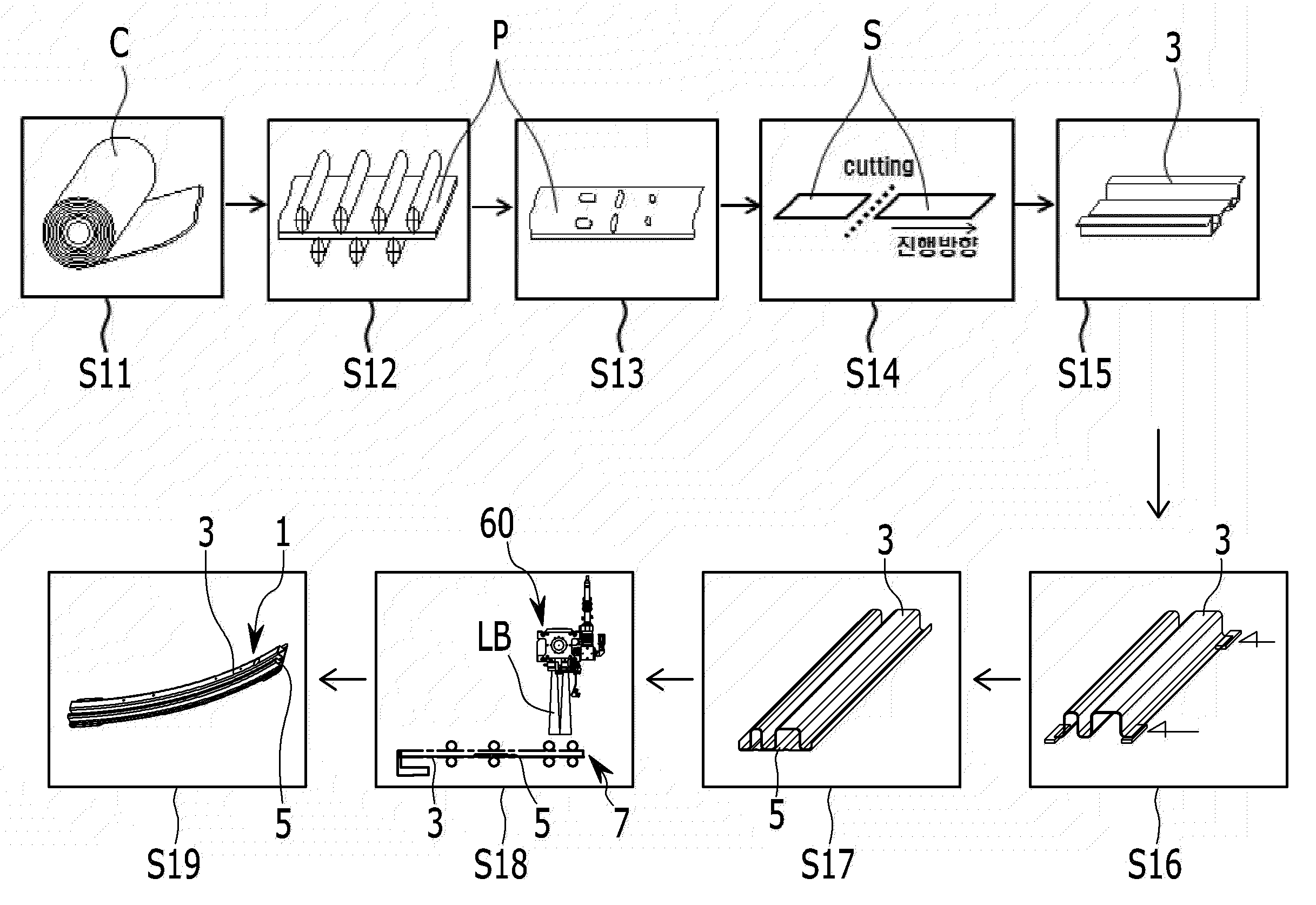
도 4 및 도 5를 참조하면, 본 발명의 실시 예에 따른 롤 포밍 방법은 공정방향 전방으로부터 언코일단계(S11), 피딩단계(S12), 피어싱단계(S13), 컷팅단계(S14), 롤포밍단계(S15), 사이징단계(S16), 메리지단계(S17), 용접단계(S18) 그리고 밴딩단계(S19)가 순차적으로 이루어진다.4 and 5, a roll forming method according to an embodiment of the present invention includes an uncoiling step S11, a feeding step S12, a piercing step S13, a cutting step S14, The forming step S15, the sizing step S16, the merge step S17, the welding step S18, and the bending step S19 are sequentially performed.
상기 언코일단계(S11)는 공정라인의 전방에서 언코일러(UC)를 통하여 소재가 되는 코일(C)을 공정 진행방향으로 풀어주게 된다.In the uncoil step S11, the coil C, which becomes the material, is released in the process direction in front of the process line through the uncoiler UC.
이와 같이 상기 언코일러(UC)로부터 풀려나온 코일(C)은 상기 피딩단계(S12)로 공급된다.Thus, the coil C released from the uncoiler UC is supplied to the feeding step S12.
상기 피딩단계(S12)는 언코일러로부터 풀려 나온 코일을 평판의 패널(P)로 펴주면서 공정 진행방향으로 공급하여 주게 된다. 이러한 피딩단계(S12)는 스트레이트너 등의 설비를 이용하여 진행할 수 있다. In the feeding step S12, the coil unwound from the uncoiler is fed to the flat panel P and fed to the process advancing direction. The feeding step S12 may be performed using a straightener or the like.
상기 피딩단계(S12)로부터 평평하게 펴진 평판의 패널(P)은 피어싱단계(S13)로 공급된다. From the feeding step S12, the flat panel P spread out flat is supplied to the piercing step S13.
상기 피어싱단계(S13)는 피딩단계(S12)의 후방에서, 피어싱 프레스를 이용하여 피딩단계(S12)로부터 공급된 패널(P)에 성형될 빔류의 조립을 위한 여러 용도의 구멍을 피어싱 성형하게 된다. 이러한 피어싱단계(S13)는 상기한 피어싱 프레스가 적용될 수 있으나, 브레이크스 프레스 등을 적용하여 진행할 수도 있다.The piercing step S13 is to pierce holes for various uses for assembling the beam to be formed in the panel P supplied from the feeding step S12 by using a piercing press at the rear of the feeding step S12 . In the piercing step S13, the above-described piercing press may be applied, but the piercing press may be applied.
상기 피어싱단계(S13)로부터 피어싱 성형된 패널(P)은 컷팅단계(S14)로 공급된다. The pierced panel P from the piercing step S13 is supplied to the cutting step S14.
상기 컷팅단계(S14)는 피어싱단계(S13)의 후방에서, 블랭킹 프레스를 이용하여 피어싱단계(S13)로부터 공급된 패널(P)을 일정 길이로 컷팅하여 일정 규격의 시트(S)로 재단한다.The cutting step S14 cuts the panel P supplied from the piercing step S13 to a predetermined length and cuts the sheet S to a predetermined size using a blanking press behind the piercing step S13.
여기서, 상기 컷팅단계(S14)는 블랭킹 프레스를 이용하여 패널(P)을 시트(S)로 절단할 수 있으나, 블랭킹 프레스 대신 레이저 절단기, 또는 런닝 커터 등을 이용하여 재단할 수도 있다. 또한, 상기 블랭킹 프레스에 의해 절단되는 시트(S)는 그 규격이 최종 성형 제품의 길이에 맞추어 재단된다.Here, in the cutting step S14, the panel P may be cut into the sheet S using a blanking press, but it may be cut using a laser cutter or a running cutter instead of the blanking press. The sheet S to be cut by the blanking press is cut in accordance with the length of the finished product.
상기 컷팅단계(S14)로부터 재단된 시트(S)는 롤포밍단계(S15)로 공급된다.The sheet S cut from the cutting step S14 is supplied to the roll forming step S15.
상기 롤포밍단계(S15)는 컷팅단계(S14)의 후방에서, 피어싱단계(S13)에 피어싱 성형되어 다시 컷팅단계(S14)에서 재단된 시트(S)를 적어도 10단 이상의 롤 포머가 배치된 롤 포밍 유닛(10)을 통해 순차적으로 절곡 성형하여 단품 성형빔(3)의 형상으로 롤 포밍 성형하게 된다. 이때, 상기 롤포밍단계(S15)에서는 공급되는 시트(S)를 개구간(개단면)을 갖는 단품 성형빔(3)으로 성형롤을 통하여 다단 절곡 성형하게 된다. The roll forming step S15 is a step of forming a sheet S which has been pierced in the piercing step S13 and cut in the cutting step S14 at a position rearward of the cutting step S14, And is subjected to roll forming in the shape of the single
상기 롤포밍단계(S15)에서 롤 포밍 성형된 단품 성형빔(3)은 사이징단계(S16)로 공급된다.In the roll forming step S15, the single-
상기 사이징단계(S16)는 롤포밍단계(S15)의 후방에서, 사이징 프레스(20)를 이용하여 단품 성형빔(3)의 양 끝단을 교정한다. 상기 사이징단계(S16)는 사이징 프레스(20)를 통하여 단품 성형빔(3)의 양 끝단을 프레싱 하며, 그 단품 성형빔(3)을 설정된 형상 및 치수로 교정 성형하게 된다.The sizing step S16 is to calibrate both ends of the single
여기서, 상기 사이징단계(S16)에서 사이징 프레스(20)를 통해 양 끝단이 교정 성형된 단품 성형빔(3)은 도 6a에서와 같이, 하부로 개방된 개구간을 가진 개단면을 형성하고 있다.In the sizing step S16, the single-
상기 사이징단계(S16)로부터 양 끝단이 교정 성형된 단품 성형빔(3)은 메리지단계(S17)로 공급된다.From the sizing step S16, the single-
상기 메리지단계(S17)는 사이징단계(S16)의 후방에서, 직선재 타입의 보강빔(5)이 로딩되어 있는 메리지 프레스(30)로 사이징단계(S16)에서 피딩된 단품 성형빔(3)을 이송하고, 그 메리지 프레스(30)를 통하여 단품 성형빔(3)과 보강빔(5)을 결합한다. 상기 메리지단계(S17)에서 메리지 프레스(30)는 단품 성형빔(3)과 보강빔(5)을 가압하며 결합하게 된다.The merge step S17 is performed after the sizing step S16 is carried out by using the single
여기서, 상기 보강빔(5)은 별도의 프레스 공정에서 프레스 가공된 것으로, 도 6b에서와 같이, 평판 형태에서 길이 방향을 따라 복수의 절곡 성형부(6)를 형성하고 있으며, 그 절곡 성형부(6)는 보강빔(5)의 폭 방향을 따라 설정된 간격으로 이격되게 형성된다.6B, the reinforcing
한편, 상기 사이징단계(S16)에서 단품 성형빔(3)의 양 끝단을 교정하는 과정에, 본 발명의 실시 예에서는 도 5 및 도 7에서와 같이, 메리지 프레스(30)를 공정 진행방향에 교차하는 방향으로 이동시키며, 상기한 바와 같은 보강빔(5)을 제1 이송유닛(40)을 통하여 메리지 프레스(30)에 로딩하고, 그 메리지 프레스(30)를 공정 진행방향으로 다시 이동시킨다.Meanwhile, in the process of calibrating both ends of the single
이 경우, 상기 제1 이송유닛(40)은 공정 진행방향 외측에서 보강빔(5)을 그리핑(당 업계에서는 통상 클램핑 또는 규제라고도 한다) 한 상태로 그 보강빔(5)을 메리지 프레스(30)에 공정 진행방향으로 로딩한다.In this case, the
그리고, 상기 메리지 프레스(30)는 당 업계에 널리 알려진 공지 기술의 서보모터, 리드(또는 볼)스크류, 및 가이드 구조를 포함하는 이동장치에 의해 공정 진행방향에 교차하는 방향(공정 진행방향의 외측 방향)으로 이동될 수 있고, 다시 공정 진행방향으로 이동될 수 있다.The
상기한 바와 같은 메리지단계(S17)를 더욱 구체적으로 설명하면, 상기 메리지단계(S17)에서는 보강빔(5)이 메리지 프레스(30)에 공정 진행방향으로 로딩된 상태에서, 사이징단계(S16)로부터 공급된 단품 성형빔(3)을 제2 이송유닛(50)을 통하여 메리지 프레스(30)의 보강빔(5) 위에 공정 진행방향으로 로딩한다.The merge step (S17) as described above will be described in more detail. In the merge step (S17), the reinforcing beam (5) is loaded on the merge press (30) The supplied single-
상기 메리지단계(S17)에서는 제2 이송유닛(50)이 사이징단계(S16)로부터 공급된 단품 성형빔(3)을 그리핑 한 상태로 공정 진행방향에 수직한 방향(상하 방향) 및 그 공정 진행방향(수평방향)으로 이송하며, 메리지 프레스(30)의 보강빔(5) 위에 단품 성형빔(3)을 공정 진행방향으로 로딩한다.In the merge step S17, the
여기서, 상기 제2 이송유닛(50)은 도 5 및 도 7에서와 같이, 공정 진행방향의 상측에서 하측 방향으로 이동하며, 사이징단계(S16)로부터 공급된 단품 성형빔(3)을 그리핑(당 업계에서는 통상 클램핑 또는 규제라고도 한다)한다.5 and 7, the
그리고, 상기 제2 이송유닛(50)은 단품 성형빔(3)을 그리핑 한 상태로, 다시 상측 방향으로 이동하며, 가이드 레일을 따라 공정 진행방향으로 이동하고, 메리지 프레스(30)의 상측에서 하측 방향으로 이동하며, 메리지 프레스(30)의 보강빔(5) 위에 단품 성형빔(3)을 공정 진행방향으로 로딩한다.The
이에 상기 메리지단계(S17)에서는 메리지 프레스(30)를 통하여 단품 성형빔(3)과 보강빔(5)을 메리지 결합한 도 6c에서와 같은 결합체(7)를 용접단계(S18)로 공급한다.In the merge step S17, the assembled
상기 용접단계(S18)는 메리지단계(S17)의 후방에서, 메리지 프레스(30)에 의해 메리지 결합된 단품 성형빔(3)과 보강빔(5)의 결합체(7)를 레이저 용접기(60)를 이용하여 레이저 용접한다.In the welding step S18, the combined
상기 용접단계(S18)에서는 레이저 용접기(60)의 레이저 발진기로부터 발진된 레이저빔을 레이저 옵틱 헤드를 통해 단품 성형빔(3)과 보강빔(5)의 결합체(7)에 조사하여 그 단품 성형빔(3)과 보강빔(5)을 레이저 용접한다.In the welding step S18, the laser beam emitted from the laser oscillator of the
이 경우, 상기 용접단계(S18)에서는 도 6d에서와 같이, 결합체(7)의 보강빔(5)을 하측에 두고 그 보강빔(5)과 상측에서 맞대어진 단품 성형빔(3)의 개방 단부에 레이저빔(LB)을 조사하여 레이저 용접을 수행한다.In this case, in the welding step S18, as shown in FIG. 6D, the reinforcing
여기서, 상기 용접단계(S18)에서는 결합체(7)에 대한 레이저빔의 조사 시, 도 5에서와 같은 서보모터(70)를 통해 결합체(7)의 피딩 속도를 제어하며 레이저 용접을 수행한다.Here, in the welding step S18, when the laser beam is irradiated to the
상기 용접단계(S18)는 단품 성형빔(3)의 개방 단부와 보강빔(5)을 레이저 용접한 도 6e에서와 같은 접합체(9)를 밴딩단계(S19)로 공급한다.The welding step S18 supplies the
상기 밴딩단계(S19)는 용접단계(S18) 후방에서, 그 용접단계(S18)에서 레이저 용접된 접합체(9)를 라운드 벤더(80)를 통해 일정 곡률로 성형하여 일정 곡률 및 일정 길이의 최종 성형빔으로 밴딩하여 도 3에서와 같은 범퍼빔(1)을 생산하게 된다.The bending step S19 is a step of forming the bonded
즉, 상기 밴딩단계(S19)에서는 단품 성형빔(3)과 보강빔(5)의 접합체(9)를 일정 곡률로 밴딩하며, 단품 성형빔(3)으로서의 전방 레일과, 보강빔(5)으로서의 후방 레일이 일체로 접합되어 폐구간을 형성하고 있는 일정 곡률 및 일정 길이의 범퍼빔(1)으로 성형한다.That is, in the bending step S19, the bonded
따라서, 상기한 바와 같은 단계별 공정을 갖는 본 발명의 실시 예에 따른 롤 포밍 방법에 의하면, 단품 성형빔(3)의 롤 포밍 성형, 단품 성형빔(3)과 보강빔(5)의 용접 및 그 용접된 단품 성형빔(3)과 보강빔(5)의 곡률 성형을 롤 포밍 성형 공정 라인 내에서 한번에 수행할 수 있다.Therefore, according to the roll forming method according to the embodiment of the present invention having the steps as described above, the roll forming of the single
이로써, 본 발명의 실시 예에서는 종래 기술과 같은 별도의 보강빔 성형 공정 및 용접 공정 등의 추가 공정을 배제할 수 있으므로, 공정 사이클 타임을 줄일 수 있고, 설비 투자비, 작업인원 및 설비 설치공간을 절감하는 효과가 있다.As a result, in the embodiment of the present invention, it is possible to exclude additional reinforcing beam forming processes and additional processes such as welding processes as in the prior art, thereby reducing the process cycle time and reducing the facility investment cost, .
이상을 통해 본 발명의 바람직한 실시 예에 대하여 설명하였지만, 본 발명은 이에 한정되는 것이 아니고 특허청구범위와 발명의 상세한 설명 및 첨부한 도면의 범위 안에서 여러 가지로 변형하여 실시하는 것이 가능하고 이 또한 본 발명의 범위에 속하는 것은 당연하다.While the present invention has been particularly shown and described with reference to exemplary embodiments thereof, it is to be understood that the invention is not limited to the disclosed exemplary embodiments, but, on the contrary, And it goes without saying that the invention belongs to the scope of the invention.
1... 범퍼 빔 3... 단품 성형빔
5... 보강빔 6... 절곡 성형부
7... 결합체 9... 접합체
10... 롤 포밍 유닛 20... 사이징 프레스
30... 메리지 프레스 40... 제1 이송유닛
50... 제2 이송유닛 60... 레이저 용접기
70... 서보모터 80... 라운드 벤더
C... 코일 LB... 레이저 빔
P... 패널 S... 시트
UC... 언코일러1 ...
5 ... reinforcing
7 ...
10 ...
30 ... Merge
50 ...
70 ...
C ... coil LB ... laser beam
P ... Panel S ... Sheet
UC ... Unclear
Claims (11)
공정라인의 전방에서 언코일러를 통하여 소재가 되는 코일을 공정 진행방향으로 풀어주는 언코일단계;
상기 언코일러로부터 풀려 나온 코일을 평판의 패널로 펴주면서 공정 진행방향으로 공급하여 주는 피딩단계;
상기 피딩단계의 후방에서, 피어싱 프레스를 이용하여 상기 피딩단계로부터 공급된 패널에 성형될 빔류의 조립을 위한 여러 용도의 구멍을 피어싱 성형하는 피어싱단계;
상기 피어싱단계의 후방에서, 블랭킹 프레스를 이용하여 상기 피어싱단계로부터 공급된 패널을 일정 길이로 컷팅하여 일정 규격의 시트로 재단하는 컷팅단계;
상기 컷팅단계의 후방에서, 상기 피어싱 성형된 시트를 적어도 10단 이상의 롤 포머가 배치된 롤 포밍 유닛을 통하여 순차적으로 절곡 성형하여 단품 성형빔의 형상으로 롤 포밍 성형하는 롤포밍단계;
상기 롤포밍단계의 후방에서, 직선재 타입의 보강빔이 로딩되어 있는 메리지 프레스로 상기 단품 성형빔을 이송하고, 상기 메리지 프레스를 통하여 상기 단품 성형빔과 보강빔을 결합하는 메리지단계;
상기 메리지단계의 후방에서, 상기 단품 성형빔과 보강빔의 결합체를 레이저 용접기를 통하여 레이저 용접하는 용접단계; 및
상기 롤포밍단계의 후방에서, 상기 단품 성형빔과 보강빔의 접합체를 라운드 벤더를 통하여 일정 곡률로 성형하며 최종 성형빔으로 밴딩하는 밴딩단계;
를 포함하고,
상기 메리지단계에서는, 상기 메리지 프레스를 공정 진행방향에 교차하는 방향으로 이동시키며, 상기 보강빔을 제1 이송유닛을 통하여 상기 메리지 프레스에 로딩하고, 상기 메리지 프레스를 공정 진행방향으로 다시 이동시키는 것을 특징으로 하는 롤 포밍 방법.In the roll forming method,
An uncoiling step of loosening the coil as a material through the uncoiler in the front of the process line in the process direction;
A feeding step of feeding a coil unwound from the uncoiler to a process advancing direction while spreading the coil with a flat panel;
A piercing step of piercing a plurality of holes for assembling a beam to be formed into a panel supplied from the feeding step using a piercing press, behind the feeding step;
A cutting step of cutting a panel supplied from the piercing step to a predetermined length using a blanking press at a rear side of the piercing step and cutting it into a sheet of a predetermined standard;
A roll forming step of forming the piercing-formed sheet in a sequential manner through a roll forming unit in which at least ten rollers are disposed, and performing roll forming in the shape of a single piece forming beam at a rear side of the cutting step;
A merge step of conveying the single-piece forming beam to a merge press in which a reinforcing beam of a rectilinear type is loaded at the rear of the roll forming step, and combining the single-piece forming beam and the reinforcing beam through the merge press;
A welding step of laser welding a combined body of the single-piece forming beam and the reinforcing beam through a laser welder at a rear side of the merge step; And
A bending step of forming a bonded body of the single piece forming beam and the reinforcing beam at a predetermined curvature through a round bender at the rear of the roll forming step and bending the single bonded body with a final forming beam;
Lt; / RTI >
In the merge step, the merge press is moved in a direction crossing the process advancing direction, the reinforcement beam is loaded into the merge press through the first conveying unit, and the merge press is moved again in the process advancing direction .
상기 롤포밍단계에서는,
상기 피어싱 성형된 시트를 개구간을 가진 단품 성형빔으로 롤 포밍 성형하는 것을 특징으로 하는 롤 포밍 방법.The method according to claim 1,
In the roll forming step,
Wherein the piercing-formed sheet is roll-formed by a single-piece molding beam having an opening.
상기 메리지단계에서는,
상기 롤포밍단계로부터 공급된 상기 단품 성형빔을 제2 이송유닛을 통하여 상기 메리지 프레스의 보강빔 위에 공정 진행방향으로 로딩하는 것을 특징으로 하는 롤 포밍 방법.The method according to claim 1,
In the merge step,
And the single-piece forming beam supplied from the roll forming step is loaded on the reinforcing beam of the merge press through the second conveying unit in the process advancing direction.
상기 용접단계에서는,
레이저 발진기로부터 발진된 레이저빔을 레이저 옵틱헤드를 통해 상기 단품 성형빔과 보강빔의 결합체에 조사 시, 상기 결합체의 피딩 속도를 제어하며 레이저 용접을 수행하는 것을 특징으로 하는 롤 포밍 방법.The method according to claim 1,
In the welding step,
Wherein when the laser beam emitted from the laser oscillator is irradiated to the combined body of the single piece forming beam and the reinforcing beam through the laser optical head, the feeding speed of the combined body is controlled and the laser welding is performed.
상기 용접단계에서는,
상기 결합체의 보강빔을 하측에 두고 상기 보강빔과 맞대어진 상기 단품 성형빔의 개방 단부를 레이저 용접하는 것을 특징으로 하는 롤 포밍 방법.6. The method of claim 5,
In the welding step,
And the open end of the single piece forming beam which is brought into contact with the reinforcing beam is laser welded with the reinforcing beam of the combined body downward.
상기 밴딩단계에서는,
상기 접합체를 일정 곡률로 밴딩하며,
상기 단품 성형빔으로서의 전방 레일과, 상기 보강빔으로서의 후방 레일이 일체로 접합되어 폐구간을 형성하고 있는 일정 곡률 및 일정 길이의 범퍼빔으로 성형하는 것을 특징으로 하는 롤 포밍 방법.The method according to claim 1,
In the bending step,
Bending the joined body at a predetermined curvature,
Wherein the bumper beam is formed into a bumper beam having a predetermined curvature and a constant length, the front rail as the single piece forming beam and the rear rail as the reinforcing beam integrally joined to form a closed section.
공정라인의 전방에서 언코일러를 통하여 소재가 되는 코일을 공정 진행방향으로 풀어주는 언코일단계;
상기 언코일러로부터 풀려 나온 코일을 평판의 패널로 펴주면서 공정 진행방향으로 공급하여 주는 피딩단계;
상기 피딩단계의 후방에서, 피어싱 프레스를 이용하여 상기 피딩단계로부터 공급된 패널에 성형될 빔류의 조립을 위한 여러 용도의 구멍을 피어싱 성형하는 피어싱단계;
상기 피어싱단계의 후방에서, 블랭킹 프레스를 이용하여 상기 피어싱단계로부터 공급된 패널을 일정 길이로 컷팅하여 일정 규격의 시트로 재단하는 컷팅단계;
상기 컷팅단계의 후방에서, 상기 피어싱 성형된 시트를 적어도 10단 이상의 롤 포머가 배치된 롤 포밍 유닛을 통하여 순차적으로 절곡 성형하여 단품 성형빔의 형상으로 롤 포밍 성형하는 롤포밍단계;
상기 롤포밍단계의 후방에서, 사이징 프레스를 이용하여 상기 단품 성형빔의 양 끝단을 교정하는 사이징단계;
상기 사이징단계의 후방에서, 직선재 타입의 보강빔이 로딩되어 있는 메리지 프레스로 상기 사이징단계에서 피딩된 단품 성형빔을 이송하고, 상기 메리지 프레스를 통하여 상기 단품 성형빔과 보강빔을 결합하는 메리지단계;
상기 메리지단계의 후방에서, 상기 단품 성형빔과 보강빔의 결합체를 레이저 용접기를 통하여 레이저 용접하는 용접단계; 및
상기 롤포밍단계의 후방에서, 상기 단품 성형빔과 보강빔의 접합체를 라운드 벤더를 통하여 일정 곡률로 성형하며 최종 성형빔으로 밴딩하는 밴딩단계;
를 포함하고,
상기 메리지단계에서는, 상기 사이징단계에서 상기 단품 성형빔의 양 끝단을 교정하는 과정에, 상기 메리지 프레스를 공정 진행방향에 교차하는 방향으로 이동시키며, 상기 보강빔을 제1 이송유닛을 통하여 상기 메리지 프레스에 로딩하고, 상기 메리지 프레스를 공정 진행방향으로 다시 이동시키는 것을 특징으로 하는 롤 포밍 방법.In the roll forming method,
An uncoiling step of loosening the coil as a material through the uncoiler in the front of the process line in the process direction;
A feeding step of feeding a coil unwound from the uncoiler to a process advancing direction while spreading the coil with a flat panel;
A piercing step of piercing a plurality of holes for assembling a beam to be formed into a panel supplied from the feeding step using a piercing press, behind the feeding step;
A cutting step of cutting a panel supplied from the piercing step to a predetermined length using a blanking press at a rear side of the piercing step and cutting it into a sheet of a predetermined standard;
A roll forming step of forming the piercing-formed sheet in a sequential manner through a roll forming unit in which at least ten rollers are disposed, and performing roll forming in the shape of a single piece forming beam at a rear side of the cutting step;
A sizing step of calibrating both ends of the single piece forming beam at a rear side of the roll forming step using a sizing press;
A merge step for conveying the single-piece forming beam fed in the sizing step with a merge press loaded with a reinforcing beam of rectilinear type at the rear of the sizing step, and combining the single-piece forming beam and the reinforcing beam through the merge press; ;
A welding step of laser welding a combined body of the single-piece forming beam and the reinforcing beam through a laser welder at a rear side of the merge step; And
A bending step of forming a bonded body of the single piece forming beam and the reinforcing beam at a predetermined curvature through a round bender at the rear of the roll forming step and bending the single bonded body with a final forming beam;
Lt; / RTI >
Wherein in the merge step, in the process of correcting both ends of the single piece forming beam in the sizing step, the merge press is moved in a direction crossing the process advancing direction, and the reinforcing beam is conveyed through the first conveying unit to the merge press And moving the merchandise press back in the process advancing direction.
상기 메리지단계에서는,
상기 사이징단계로부터 공급된 상기 단품 성형빔을 제2 이송유닛을 통하여 수직 및 수평방향으로 이송하며,
상기 메리지 프레스의 보강빔 위에 상기 단품 성형빔을 공정 진행방향으로 로딩하는 것을 특징으로 하는 롤 포밍 방법.9. The method of claim 8,
In the merge step,
And the single-piece forming beam supplied from the sizing step is transferred in the vertical and horizontal directions through the second transfer unit,
Wherein the single-piece forming beam is loaded on the reinforcing beam of the mar- kage press in the process advancing direction.
상기 용접단계에서는,
레이저 발진기로부터 발진된 레이저빔을 레이저 옵틱헤드를 통해 상기 단품 성형빔과 보강빔의 결합체에 조사 시, 서보모터를 통해 상기 결합체의 피딩 속도를 제어하며 레이저 용접을 수행하는 것을 특징으로 하는 롤 포밍 방법.9. The method of claim 8,
In the welding step,
Wherein when the laser beam oscillated from the laser oscillator is irradiated to the combined body of the single piece forming beam and the reinforcing beam through the laser optical head, the feeding speed of the combined body is controlled through the servo motor and the laser welding is performed .
Priority Applications (1)
| Application Number | Priority Date | Filing Date | Title |
|---|---|---|---|
| KR1020170032055A KR101929214B1 (en) | 2017-03-14 | 2017-03-14 | Roll forming method |
Applications Claiming Priority (1)
| Application Number | Priority Date | Filing Date | Title |
|---|---|---|---|
| KR1020170032055A KR101929214B1 (en) | 2017-03-14 | 2017-03-14 | Roll forming method |
Publications (2)
| Publication Number | Publication Date |
|---|---|
| KR20180105015A KR20180105015A (en) | 2018-09-27 |
| KR101929214B1 true KR101929214B1 (en) | 2018-12-14 |
Family
ID=63719304
Family Applications (1)
| Application Number | Title | Priority Date | Filing Date |
|---|---|---|---|
| KR1020170032055A KR101929214B1 (en) | 2017-03-14 | 2017-03-14 | Roll forming method |
Country Status (1)
| Country | Link |
|---|---|
| KR (1) | KR101929214B1 (en) |
Cited By (2)
| Publication number | Priority date | Publication date | Assignee | Title |
|---|---|---|---|---|
| KR102392082B1 (en) * | 2021-04-19 | 2022-04-29 | (주)월산 | Forming method for vehicle door impact bar having pront wave part and side bending part |
| KR102392081B1 (en) * | 2021-04-19 | 2022-04-29 | (주)월산 | Forming method for vehicle door impact bar having pront wave part and side bending part |
Families Citing this family (2)
| Publication number | Priority date | Publication date | Assignee | Title |
|---|---|---|---|---|
| CN110883559B (en) * | 2019-12-13 | 2020-12-25 | 佛山市宏石激光技术有限公司 | Coil stock cutting device |
| WO2023101648A1 (en) * | 2021-11-30 | 2023-06-08 | Metalfiks Baglanti Elemanlari Sanayi Ve Ticaret Anonim Si̇rketi | A process for the production of furniture connection element cam made of metal |
-
2017
- 2017-03-14 KR KR1020170032055A patent/KR101929214B1/en active IP Right Grant
Cited By (2)
| Publication number | Priority date | Publication date | Assignee | Title |
|---|---|---|---|---|
| KR102392082B1 (en) * | 2021-04-19 | 2022-04-29 | (주)월산 | Forming method for vehicle door impact bar having pront wave part and side bending part |
| KR102392081B1 (en) * | 2021-04-19 | 2022-04-29 | (주)월산 | Forming method for vehicle door impact bar having pront wave part and side bending part |
Also Published As
| Publication number | Publication date |
|---|---|
| KR20180105015A (en) | 2018-09-27 |
Similar Documents
| Publication | Publication Date | Title |
|---|---|---|
| KR101929214B1 (en) | Roll forming method | |
| US11660652B2 (en) | Multi-tubular beam for a vehicle | |
| US8631996B2 (en) | Composite of sheet metal parts | |
| JP5033120B2 (en) | Production line and method for forming and processing profiles | |
| JP5080966B2 (en) | Production line and method for forming profiles | |
| JP4119362B2 (en) | Method and apparatus for manufacturing automotive beams | |
| CN103813882A (en) | Device and method for producing customized sheet metal strip or metal profile | |
| JP5640346B2 (en) | Manufacturing method of polygonal closed cross-section structural parts | |
| US10124387B2 (en) | Press-molded product, press-molded product producing method, and press-molded product producing apparatus | |
| JP2016059938A (en) | Pipe manufacturing method | |
| KR101895886B1 (en) | Flexible roll forming method and front side member produced by the same | |
| US9132468B2 (en) | Device and method for expanding metal elements | |
| KR20150074407A (en) | Forming method of bumper beam for vehicles | |
| KR102396221B1 (en) | Roll forming method and bumper beam manufactured using the method | |
| KR100969821B1 (en) | Roll forming system for sandwich panel and method thereof | |
| CN104364026B (en) | There is the manufacture method and the device that close cross section structure part without flange of curved shape | |
| KR100894817B1 (en) | Roll forming system for simultaneous forming and method thereof | |
| KR101680565B1 (en) | Roll forming method | |
| KR20180075287A (en) | Flexible roll forming method and front side member produced by the same | |
| KR101420009B1 (en) | Method of manufacturing coupled torsion beam typed suspension in vehicle | |
| KR20150073807A (en) | Roll forming method | |
| US4947014A (en) | Method and apparatus for producing can bodies of a non-circular cross-section | |
| KR101689578B1 (en) | Flexible roll forming method | |
| KR101536404B1 (en) | Forming apparatus for a metal border | |
| KR101517867B1 (en) | Car door impact beam manufacturing method |
Legal Events
| Date | Code | Title | Description |
|---|---|---|---|
| A201 | Request for examination | ||
| E902 | Notification of reason for refusal | ||
| E701 | Decision to grant or registration of patent right | ||
| GRNT | Written decision to grant |