KR101872984B1 - Vehicle pose control apparatus - Google Patents
Vehicle pose control apparatus Download PDFInfo
- Publication number
- KR101872984B1 KR101872984B1 KR1020110094639A KR20110094639A KR101872984B1 KR 101872984 B1 KR101872984 B1 KR 101872984B1 KR 1020110094639 A KR1020110094639 A KR 1020110094639A KR 20110094639 A KR20110094639 A KR 20110094639A KR 101872984 B1 KR101872984 B1 KR 101872984B1
- Authority
- KR
- South Korea
- Prior art keywords
- roll
- vehicle
- pitch
- vehicle body
- control
- Prior art date
Links
- 238000013016 damping Methods 0.000 claims abstract description 115
- 230000000452 restraining effect Effects 0.000 claims abstract description 25
- 230000006872 improvement Effects 0.000 claims description 49
- 238000005096 rolling process Methods 0.000 claims description 22
- 239000000725 suspension Substances 0.000 claims description 21
- 239000006096 absorbing agent Substances 0.000 claims description 10
- 230000035939 shock Effects 0.000 claims description 10
- 230000007246 mechanism Effects 0.000 claims description 3
- 238000013459 approach Methods 0.000 claims description 2
- 230000005540 biological transmission Effects 0.000 claims 2
- 230000003247 decreasing effect Effects 0.000 claims 1
- 230000001133 acceleration Effects 0.000 description 36
- 238000004364 calculation method Methods 0.000 description 29
- 238000012937 correction Methods 0.000 description 18
- 238000001514 detection method Methods 0.000 description 12
- 230000001629 suppression Effects 0.000 description 10
- 239000000470 constituent Substances 0.000 description 9
- 230000005484 gravity Effects 0.000 description 9
- 238000010586 diagram Methods 0.000 description 7
- 238000012546 transfer Methods 0.000 description 5
- 230000008859 change Effects 0.000 description 4
- 230000007423 decrease Effects 0.000 description 4
- 230000009189 diving Effects 0.000 description 3
- 238000000034 method Methods 0.000 description 3
- 230000008569 process Effects 0.000 description 3
- 230000014509 gene expression Effects 0.000 description 2
- 238000012545 processing Methods 0.000 description 2
- 230000008602 contraction Effects 0.000 description 1
- 238000007796 conventional method Methods 0.000 description 1
- 230000006866 deterioration Effects 0.000 description 1
- 230000009467 reduction Effects 0.000 description 1
- 230000000630 rising effect Effects 0.000 description 1
- 230000006641 stabilisation Effects 0.000 description 1
- 238000011105 stabilization Methods 0.000 description 1
- 230000000087 stabilizing effect Effects 0.000 description 1
- 230000001052 transient effect Effects 0.000 description 1
- 230000007704 transition Effects 0.000 description 1
Images


Classifications
-
- B—PERFORMING OPERATIONS; TRANSPORTING
- B60—VEHICLES IN GENERAL
- B60G—VEHICLE SUSPENSION ARRANGEMENTS
- B60G17/00—Resilient suspensions having means for adjusting the spring or vibration-damper characteristics, for regulating the distance between a supporting surface and a sprung part of vehicle or for locking suspension during use to meet varying vehicular or surface conditions, e.g. due to speed or load
- B60G17/06—Characteristics of dampers, e.g. mechanical dampers
- B60G17/08—Characteristics of fluid dampers
-
- B—PERFORMING OPERATIONS; TRANSPORTING
- B60—VEHICLES IN GENERAL
- B60W—CONJOINT CONTROL OF VEHICLE SUB-UNITS OF DIFFERENT TYPE OR DIFFERENT FUNCTION; CONTROL SYSTEMS SPECIALLY ADAPTED FOR HYBRID VEHICLES; ROAD VEHICLE DRIVE CONTROL SYSTEMS FOR PURPOSES NOT RELATED TO THE CONTROL OF A PARTICULAR SUB-UNIT
- B60W30/00—Purposes of road vehicle drive control systems not related to the control of a particular sub-unit, e.g. of systems using conjoint control of vehicle sub-units
- B60W30/02—Control of vehicle driving stability
-
- B—PERFORMING OPERATIONS; TRANSPORTING
- B60—VEHICLES IN GENERAL
- B60G—VEHICLE SUSPENSION ARRANGEMENTS
- B60G17/00—Resilient suspensions having means for adjusting the spring or vibration-damper characteristics, for regulating the distance between a supporting surface and a sprung part of vehicle or for locking suspension during use to meet varying vehicular or surface conditions, e.g. due to speed or load
- B60G17/015—Resilient suspensions having means for adjusting the spring or vibration-damper characteristics, for regulating the distance between a supporting surface and a sprung part of vehicle or for locking suspension during use to meet varying vehicular or surface conditions, e.g. due to speed or load the regulating means comprising electric or electronic elements
- B60G17/016—Resilient suspensions having means for adjusting the spring or vibration-damper characteristics, for regulating the distance between a supporting surface and a sprung part of vehicle or for locking suspension during use to meet varying vehicular or surface conditions, e.g. due to speed or load the regulating means comprising electric or electronic elements characterised by their responsiveness, when the vehicle is travelling, to specific motion, a specific condition, or driver input
- B60G17/0162—Resilient suspensions having means for adjusting the spring or vibration-damper characteristics, for regulating the distance between a supporting surface and a sprung part of vehicle or for locking suspension during use to meet varying vehicular or surface conditions, e.g. due to speed or load the regulating means comprising electric or electronic elements characterised by their responsiveness, when the vehicle is travelling, to specific motion, a specific condition, or driver input mainly during a motion involving steering operation, e.g. cornering, overtaking
-
- B—PERFORMING OPERATIONS; TRANSPORTING
- B60—VEHICLES IN GENERAL
- B60W—CONJOINT CONTROL OF VEHICLE SUB-UNITS OF DIFFERENT TYPE OR DIFFERENT FUNCTION; CONTROL SYSTEMS SPECIALLY ADAPTED FOR HYBRID VEHICLES; ROAD VEHICLE DRIVE CONTROL SYSTEMS FOR PURPOSES NOT RELATED TO THE CONTROL OF A PARTICULAR SUB-UNIT
- B60W10/00—Conjoint control of vehicle sub-units of different type or different function
- B60W10/18—Conjoint control of vehicle sub-units of different type or different function including control of braking systems
- B60W10/184—Conjoint control of vehicle sub-units of different type or different function including control of braking systems with wheel brakes
-
- B—PERFORMING OPERATIONS; TRANSPORTING
- B60—VEHICLES IN GENERAL
- B60W—CONJOINT CONTROL OF VEHICLE SUB-UNITS OF DIFFERENT TYPE OR DIFFERENT FUNCTION; CONTROL SYSTEMS SPECIALLY ADAPTED FOR HYBRID VEHICLES; ROAD VEHICLE DRIVE CONTROL SYSTEMS FOR PURPOSES NOT RELATED TO THE CONTROL OF A PARTICULAR SUB-UNIT
- B60W10/00—Conjoint control of vehicle sub-units of different type or different function
- B60W10/22—Conjoint control of vehicle sub-units of different type or different function including control of suspension systems
-
- B—PERFORMING OPERATIONS; TRANSPORTING
- B60—VEHICLES IN GENERAL
- B60W—CONJOINT CONTROL OF VEHICLE SUB-UNITS OF DIFFERENT TYPE OR DIFFERENT FUNCTION; CONTROL SYSTEMS SPECIALLY ADAPTED FOR HYBRID VEHICLES; ROAD VEHICLE DRIVE CONTROL SYSTEMS FOR PURPOSES NOT RELATED TO THE CONTROL OF A PARTICULAR SUB-UNIT
- B60W30/00—Purposes of road vehicle drive control systems not related to the control of a particular sub-unit, e.g. of systems using conjoint control of vehicle sub-units
- B60W30/02—Control of vehicle driving stability
- B60W30/025—Control of vehicle driving stability related to comfort of drivers or passengers
-
- B—PERFORMING OPERATIONS; TRANSPORTING
- B60—VEHICLES IN GENERAL
- B60W—CONJOINT CONTROL OF VEHICLE SUB-UNITS OF DIFFERENT TYPE OR DIFFERENT FUNCTION; CONTROL SYSTEMS SPECIALLY ADAPTED FOR HYBRID VEHICLES; ROAD VEHICLE DRIVE CONTROL SYSTEMS FOR PURPOSES NOT RELATED TO THE CONTROL OF A PARTICULAR SUB-UNIT
- B60W40/00—Estimation or calculation of non-directly measurable driving parameters for road vehicle drive control systems not related to the control of a particular sub unit, e.g. by using mathematical models
- B60W40/10—Estimation or calculation of non-directly measurable driving parameters for road vehicle drive control systems not related to the control of a particular sub unit, e.g. by using mathematical models related to vehicle motion
-
- B—PERFORMING OPERATIONS; TRANSPORTING
- B60—VEHICLES IN GENERAL
- B60G—VEHICLE SUSPENSION ARRANGEMENTS
- B60G2400/00—Indexing codes relating to detected, measured or calculated conditions or factors
- B60G2400/05—Attitude
- B60G2400/052—Angular rate
- B60G2400/0521—Roll rate
-
- B—PERFORMING OPERATIONS; TRANSPORTING
- B60—VEHICLES IN GENERAL
- B60G—VEHICLE SUSPENSION ARRANGEMENTS
- B60G2400/00—Indexing codes relating to detected, measured or calculated conditions or factors
- B60G2400/05—Attitude
- B60G2400/052—Angular rate
- B60G2400/0522—Pitch rate
-
- B—PERFORMING OPERATIONS; TRANSPORTING
- B60—VEHICLES IN GENERAL
- B60G—VEHICLE SUSPENSION ARRANGEMENTS
- B60G2400/00—Indexing codes relating to detected, measured or calculated conditions or factors
- B60G2400/05—Attitude
- B60G2400/052—Angular rate
- B60G2400/0523—Yaw rate
-
- B—PERFORMING OPERATIONS; TRANSPORTING
- B60—VEHICLES IN GENERAL
- B60G—VEHICLE SUSPENSION ARRANGEMENTS
- B60G2400/00—Indexing codes relating to detected, measured or calculated conditions or factors
- B60G2400/20—Speed
- B60G2400/204—Vehicle speed
-
- B—PERFORMING OPERATIONS; TRANSPORTING
- B60—VEHICLES IN GENERAL
- B60G—VEHICLE SUSPENSION ARRANGEMENTS
- B60G2400/00—Indexing codes relating to detected, measured or calculated conditions or factors
- B60G2400/25—Stroke; Height; Displacement
- B60G2400/252—Stroke; Height; Displacement vertical
-
- B—PERFORMING OPERATIONS; TRANSPORTING
- B60—VEHICLES IN GENERAL
- B60G—VEHICLE SUSPENSION ARRANGEMENTS
- B60G2400/00—Indexing codes relating to detected, measured or calculated conditions or factors
- B60G2400/40—Steering conditions
- B60G2400/41—Steering angle
-
- B—PERFORMING OPERATIONS; TRANSPORTING
- B60—VEHICLES IN GENERAL
- B60G—VEHICLE SUSPENSION ARRANGEMENTS
- B60G2500/00—Indexing codes relating to the regulated action or device
- B60G2500/10—Damping action or damper
-
- B—PERFORMING OPERATIONS; TRANSPORTING
- B60—VEHICLES IN GENERAL
- B60G—VEHICLE SUSPENSION ARRANGEMENTS
- B60G2800/00—Indexing codes relating to the type of movement or to the condition of the vehicle and to the end result to be achieved by the control action
- B60G2800/01—Attitude or posture control
- B60G2800/012—Rolling condition
-
- B—PERFORMING OPERATIONS; TRANSPORTING
- B60—VEHICLES IN GENERAL
- B60G—VEHICLE SUSPENSION ARRANGEMENTS
- B60G2800/00—Indexing codes relating to the type of movement or to the condition of the vehicle and to the end result to be achieved by the control action
- B60G2800/01—Attitude or posture control
- B60G2800/014—Pitch; Nose dive
-
- B—PERFORMING OPERATIONS; TRANSPORTING
- B60—VEHICLES IN GENERAL
- B60W—CONJOINT CONTROL OF VEHICLE SUB-UNITS OF DIFFERENT TYPE OR DIFFERENT FUNCTION; CONTROL SYSTEMS SPECIALLY ADAPTED FOR HYBRID VEHICLES; ROAD VEHICLE DRIVE CONTROL SYSTEMS FOR PURPOSES NOT RELATED TO THE CONTROL OF A PARTICULAR SUB-UNIT
- B60W2520/00—Input parameters relating to overall vehicle dynamics
- B60W2520/16—Pitch
-
- B—PERFORMING OPERATIONS; TRANSPORTING
- B60—VEHICLES IN GENERAL
- B60W—CONJOINT CONTROL OF VEHICLE SUB-UNITS OF DIFFERENT TYPE OR DIFFERENT FUNCTION; CONTROL SYSTEMS SPECIALLY ADAPTED FOR HYBRID VEHICLES; ROAD VEHICLE DRIVE CONTROL SYSTEMS FOR PURPOSES NOT RELATED TO THE CONTROL OF A PARTICULAR SUB-UNIT
- B60W2520/00—Input parameters relating to overall vehicle dynamics
- B60W2520/18—Roll
-
- B—PERFORMING OPERATIONS; TRANSPORTING
- B60—VEHICLES IN GENERAL
- B60W—CONJOINT CONTROL OF VEHICLE SUB-UNITS OF DIFFERENT TYPE OR DIFFERENT FUNCTION; CONTROL SYSTEMS SPECIALLY ADAPTED FOR HYBRID VEHICLES; ROAD VEHICLE DRIVE CONTROL SYSTEMS FOR PURPOSES NOT RELATED TO THE CONTROL OF A PARTICULAR SUB-UNIT
- B60W2710/00—Output or target parameters relating to a particular sub-units
- B60W2710/22—Suspension systems
- B60W2710/226—Damping
-
- B—PERFORMING OPERATIONS; TRANSPORTING
- B60—VEHICLES IN GENERAL
- B60W—CONJOINT CONTROL OF VEHICLE SUB-UNITS OF DIFFERENT TYPE OR DIFFERENT FUNCTION; CONTROL SYSTEMS SPECIALLY ADAPTED FOR HYBRID VEHICLES; ROAD VEHICLE DRIVE CONTROL SYSTEMS FOR PURPOSES NOT RELATED TO THE CONTROL OF A PARTICULAR SUB-UNIT
- B60W2720/00—Output or target parameters relating to overall vehicle dynamics
- B60W2720/16—Pitch
Landscapes
- Engineering & Computer Science (AREA)
- Mechanical Engineering (AREA)
- Transportation (AREA)
- Automation & Control Theory (AREA)
- Chemical & Material Sciences (AREA)
- Combustion & Propulsion (AREA)
- Physics & Mathematics (AREA)
- Mathematical Physics (AREA)
- Vehicle Body Suspensions (AREA)
Abstract
차량 주행 시의 선회 조작성, 조종 안정성, 승차감을 향상시킬 수 있도록 한 차체 자세 제어 장치를 제공한다.
차량 주행 시의 타이어가 상용 영역에 있는 동안은, 롤 레이트에 따라 목표 피치 레이트를 산출하는 피치 제어부(23)쪽을 롤 억제부(18)보다도 우선시킨다. 이 경우, 피치 제어부(23)에서 산출한 목표 감쇠력에 무게를 부여하고, 상기 목표 피치 레이트가 되도록 각 댐퍼(6, 9)의 감쇠력 특성을 제어한다. 타이어의 노면 그립 상태가 나쁜 한계 영역에서는, 피치 제어부(23)보다도 롤 억제부(18)쪽을 우선시키고, 롤 억제부(18)에서 산출한 목표 감쇠력에 무게를 부여한다. 이에 따라, 롤 억제 제어량을 크게 하도록 각 댐퍼(6, 9)의 감쇠력 특성을 제어한다.Provided is a vehicle body posture control device that can improve turning operability, steering stability, and ride comfort when the vehicle is running.
The pitch control section 23 for calculating the target pitch rate according to the roll rate has priority over the roll restraining section 18 while the tire during running of the vehicle is in the commercial area. In this case, weight is given to the target damping force calculated by the pitch control unit 23, and the damping force characteristics of the dampers 6 and 9 are controlled to be the target pitch rate. The roll restraining portion 18 is given priority over the pitch control portion 23 and the weight of the target damping force calculated by the roll restraining portion 18 is given in the limit region where the road surface grip state of the tire is poor. Thus, the damping force characteristics of the dampers 6 and 9 are controlled so as to increase the rolling-restraining control amount.

Description
본 발명은 예컨대 4륜 자동차 등의 차량에 적합하게 이용되는 차체 자세 제어 장치에 관한 것이다.The present invention relates to a vehicle body posture control device suitably used for a vehicle such as a four-wheeled vehicle.
일반적으로, 차량의 조타각과 차속으로부터 횡가속도를 산출하며, 이 횡가속도를 미분하여 횡가가속도를 구하고, 이 횡가가속도에 따라 전, 후, 좌, 우의 차륜측에서 각 서스펜션의 감쇠력을 전환함으로써 롤 레이트의 저감을 도모하는 구성으로 한 차체 자세 제어 장치는 알려져 있다(예컨대, 특허문헌 1 참조).Generally, the lateral acceleration is calculated from the steering angle and the vehicle speed of the vehicle, the lateral acceleration is obtained by differentiating the lateral acceleration, and the damping force of each suspension is switched on the front, rear, left, (For example, refer to Patent Document 1).
또한, 차량 주행 시의 횡가속도로부터 목표 롤각을 구하고, 그 목표 롤각에 따라 목표 피치각을 산출한 뒤에, 실제 롤각과 실제 피치각의 차를 구하여 피드백 제어(FB 제어)를 행함으로써, 차체 자세의 안정화를 도모하도록 차체측의 목표 거동을 실현하는 구성으로 한 것이 알려져 있다(예컨대, 특허문헌 2 참조).Further, by calculating the target roll angle from the lateral acceleration at the time of vehicle running and calculating the target pitch angle according to the target roll angle, the difference between the actual roll angle and the actual pitch angle is obtained and feedback control (FB control) And the target behavior on the vehicle body side is realized so as to achieve stabilization (see, for example, Patent Document 2).
한편, 차량 주행 시의 타이어가 선형 영역(예컨대, 노면의 그립 상태가 양호한 영역)에 있는지, 비선형 영역(예컨대, 노면의 그립 상태가 나쁜 영역)에 있는 지를 판단하고, 비선형 영역에 있다고 판단하였을 때에는 감쇠력 특성을 하드측으로 전환하여 조종 안정성을 향상시키는 구성으로 한 것도 알려져 있다(예컨대, 특허문헌 3 참조).On the other hand, it is determined whether the tire at the time of driving the vehicle is in a linear region (for example, a good road surface grip state) or a non-linear region (for example, a poor road surface grip state) The damping force characteristic is switched to the hard side to improve the steering stability (see, for example, Patent Document 3).
그런데, 전술한 특허문헌 1에 따른 종래 기술은, 롤 레이트의 저감에만 착안한 논리이기 때문에, 롤 레이트와 피치 레이트에 관련성이 낮은 경우나 의도하지 않은 피치 레이트가 발생한 경우에, 과도 선회 시의 필링이 나쁜 경우가 있었다.However, since the prior art according to the above-described
또한, 예컨대 특허문헌 2에 따른 종래 기술에서는, 차량 주행 시의 롤각에 따라 피치각을 발생시키기 때문에, 정상원 선회 중에서도 제어를 행할 필요가 있다. 이 때문에, 감쇠력 가변식 댐퍼의 제어에서는 승차감의 악화를 초래하는 경우가 있으며, 브레이크에 의한 제어에서는 감속해 가야 하는 문제가 있었다.Further, for example, in the conventional technique according to
그래서, 본원의 발명자들은, 롤감을 향상시키기 위해, 롤 레이트에 맞추어 피치 레이트를 제어하는 것을 검토하였다. 이 경우, 차량 주행 시의 타이어가 상용 영역인 선형 영역에 있는 동안은, 롤감의 향상을 실현할 수 있다. 그러나, 이러한 제어를 타이어의 노면 그립 상태가 나쁜 한계 영역, 즉 비선형 영역에서 계속하면, 하기와 같이 한계 성능이 저하하여 버리는 경우가 있다.Thus, the inventors of the present application have studied controlling the pitch rate in accordance with the roll rate in order to improve roll feeling. In this case, it is possible to realize an improvement in rolling feeling while the tire during running of the vehicle is in a linear region which is a commercial region. However, if such control is continued in a marginal region where the road surface grip state of the tire is bad, that is, in a non-linear region, the marginal performance may decrease as described below.
즉, 과도 롤각의 증가에 따라 하중 이동량이 증대하고, 타이어의 등가 CP(코너링 파워)가 감소한다. 또한, 서스펜션의 스트로크 증가에 따라 롤 스티어가 증대하고, 언더 스티어화가 생긴다. 더욱, 타이어의 접지성을 무시한 감쇠력 특성의 전환에 따라, 하중 변동의 증가가 발생하여 버린다.That is, as the transient roll angle increases, the load transfer amount increases and the equivalent CP (cornering power) of the tire decreases. In addition, as the stroke of the suspension increases, the roll steer increases and understeer occurs. Furthermore, the change in the damping force characteristic that ignores the grounding property of the tire causes an increase in the load fluctuation.
본 발명의 목적은, 차량 주행 시의 선회 조작성, 조종 안정성, 승차감을 향상시킬 수 있도록 한 차체 자세 제어 장치를 제공하는 것에 있다.It is an object of the present invention to provide a vehicle body posture control device capable of improving turning operability, steering stability, and ride comfort when the vehicle is running.
전술한 과제를 해결하기 위해, 청구항 1의 발명은, 차량의 차체의 자세를 제어하는 차체 자세 제어 장치로서, 롤감 향상 제어 수단과 안정성 향상 제어 수단과 차량 운동 판단 수단을 가지며, 상기 롤감 향상 제어 수단은, 상기 차체의 롤 레이트의 크기에 따라 증대하도록 상기 차체의 피치 레이트의 목표값인 목표 피치 레이트를 산출하는 목표 피치 레이트 산출 수단과, 상기 차체의 피치 레이트가 상기 목표 피치 레이트에 근접하도록 상기 차체에 대하여 피치 모멘트를 발생하는 피치 모멘트 발생 수단을 포함하여 구성되며, 상기 안정성 향상 제어 수단은, 롤을 억제하는 힘을 발생하는 롤 억제 수단에 의해 구성하고, 상기 차량 운동 판단 수단은, 차량 운동에 따라 상기 롤감 향상 제어 수단과 상기 안정성 향상 제어 수단의 제어 비율을 전환하는 구성으로 되어 있다.In order to solve the above-mentioned problems, the invention of
전술한 바와 같이, 청구항 1에 기재된 발명에 따르면, 상용 영역에서는 피치와 롤의 거동에 이상적인 결합을 갖게 할 수 있고, 주행 중의 드라이버 필링(롤감)을 향상시킬 수 있다. 또한, 한계 영역에서는 주행 안정성을 확보할 수 있다.As described above, according to the invention as set forth in
도 1은 본 발명의 제1 실시형태에 따른 차체 자세 제어 장치가 적용된 4륜 자동차를 나타내는 사시도이다.
도 2는 제1 실시형태에 따른 차체 자세 제어 장치를 나타내는 제어 블록도이다.
도 3은 도 2 중의 목표 감쇠력 산출부에 있어서 피치 모멘트로부터 각 차륜측의 목표 감쇠력을 산출하는 처리를 나타내는 제어 블록도이다.
도 4는 제2 실시형태에 따른 차체 자세 제어 장치를 나타내는 제어 블록도이다.
도 5는 제3 실시형태에 따른 차체 자세 제어 장치를 나타내는 제어 블록도이다.
도 6은 도 5 중의 전자 댐퍼 제어량 산출부에 있어서 목표 피치 모멘트와 목표 롤 모멘트로부터 각 차륜측의 목표 추력을 산출하는 처리를 나타내는 제어 블록도이다.
도 7은 제4 실시형태에 따른 차체 자세 제어 장치를 나타내는 제어 블록도이다.
도 8은 도 7 중의 가·감속 지령 산출부에 있어서 목표 피치 모멘트로부터 각 차륜측의 가·감속 지령을 산출하는 처리를 나타내는 제어 블록도이다.1 is a perspective view showing a four-wheeled vehicle to which a vehicle body posture control device according to a first embodiment of the present invention is applied.
2 is a control block diagram showing a vehicle body posture control device according to the first embodiment.
3 is a control block diagram showing a process for calculating a target damping force on each wheel side from the pitch moment in the target damping force calculating unit in Fig.
4 is a control block diagram showing the vehicle body posture control device according to the second embodiment.
5 is a control block diagram showing the vehicle body posture control device according to the third embodiment.
Fig. 6 is a control block diagram showing a process for calculating the target thrust on each wheel side from the target pitch moment and the target roll moment in the electronic damper control amount calculating unit in Fig. 5; Fig.
7 is a control block diagram showing a vehicle body posture control device according to the fourth embodiment.
Fig. 8 is a control block diagram showing processing for calculating the acceleration / deceleration commands on each wheel side from the target pitch moment in the acceleration / deceleration command calculation unit in Fig. 7; Fig.
이하, 본 발명의 실시형태에 따른 차체 자세 제어 장치를, 예컨대 4륜 자동차에 적용한 경우를 예로 들어, 첨부 도면에 따라 상세하게 설명한다.Hereinafter, the vehicle body posture control device according to the embodiment of the present invention is applied to, for example, a four-wheeled vehicle as an example, and will be described in detail with reference to the accompanying drawings.
여기서, 도 1 내지 도 3은 본 발명의 제1 실시형태를 나타내고 있다. 도면 중, 도면 부호 1은 차량의 보디를 구성하는 차체이며, 상기 차체(1)의 하측에는, 예컨대 좌, 우의 전륜(2)(한쪽만 도시)과 좌, 우의 후륜(3)(한쪽만 도시)이 마련되어 있다.Here, Figs. 1 to 3 show a first embodiment of the present invention. In the figure,
도면 부호 4, 4는 좌, 우의 전륜(2)측과 차체(1) 사이에 개재하여 마련된 전륜측의 서스펜션 장치이며, 상기 각 서스펜션 장치(4)는, 좌, 우의 현가 스프링(5)(이하, 스프링(5)이라고 함)과, 상기 각 스프링(5)과 병렬이 되어 좌, 우의 전륜(2)측과 차체(1) 사이에 마련된 좌, 우의 감쇠력 조정식 쇼크 업소버(6)(이하, 감쇠력 가변 댐퍼(6)라고 함)에 의해 구성되어 있다. 감쇠력 가변 댐퍼(6)는, 본 발명의 구성 요건인 피치 모멘트 발생 수단, 롤 억제 수단의 일부를 구성하는 것이다.
도면 부호 7, 7은 좌, 우의 후륜(3)측과 차체(1) 사이에 개재하여 마련된 후륜측의 서스펜션 장치이며, 상기 각 서스펜션 장치(7)는, 좌, 우의 현가 스프링(8)(이하, 스프링(8)이라고 함)과, 상기 각 스프링(8)과 병렬이 되어 좌, 우의 후륜(3)측과 차체(1) 사이에 마련된 좌, 우의 감쇠력 조정식 쇼크 업소버(9)(이하, 감쇠력 가변 댐퍼(9)라고 함)에 의해 구성되어 있다. 감쇠력 가변 댐퍼(9)는, 피치 모멘트 발생 수단, 롤 억제 수단의 일부를 구성하는 것이다.
여기서, 각 서스펜션 장치(4, 7)의 감쇠력 가변 댐퍼(6, 9)는, 감쇠력 조정식의 유압 완충기를 이용하여 구성된다. 그리고, 이 감쇠력 가변 댐퍼(6, 9)에는, 그 감쇠력 특성을 하드한 특성(경질 특성)으로부터 소프트한 특성(연질 특성)으로 연속적으로 조정하기 위해, 감쇠력 조정 밸브, 솔레노이드 등으로 이루어지는 액츄에이터(도시하지 않음)가 부설되어 있다. 또한, 감쇠력 조정용의 액츄에이터는, 감쇠력 특성을 반드시 연속적으로 변화시키는 구성일 필요는 없고, 2단계 또는 3단계 이상으로 단속적으로 조정하는 구성이어도 좋다. 또한, 감쇠력 가변 댐퍼(6, 9)는, 감쇠력을 전환하면 좋고, 공기 압력 댐퍼나 전자 댐퍼여도 좋다.Here, the damping force
도면 부호 10은 차체(1)에 마련된 롤 레이트 검출 수단으로서의 자이로(gyro) 등으로 이루어지는 롤 레이트 센서이며, 상기 롤 레이트 센서(10)는, 예컨대 차량의 스티어링 조작에 따라 선회 주행 시 등에 발생하는 좌, 우 방향의 롤링 진동을 검출하고, 그 검출 신호를 후술하는 컨트롤러(15)에 출력하는 것이다. 또한, 롤 레이트 검출 수단은, 롤 레이트를 검출할 수 있으면 좋고, 좌, 우 방향으로 이격하여 마련된 2개의 상하 가속도 센서의 차분을 적분하는 등의 구성이어도 좋다.
도면 부호 11은 차체(1)에 마련된 피치 레이트 검출 수단으로서의 자이로 등으로 이루어지는 피치 레이트 센서이며, 상기 피치 레이트 센서(11)는, 예컨대 차량의 가, 감속 시 등에 발생하는 전, 후 방향의 흔들림 진동을 검출하고, 그 검출 신호를 후술하는 컨트롤러(15)에 출력한다. 또한, 피치 레이트 검출 수단은, 피치 레이트를 검출할 수 있으면 좋고, 전, 후 방향으로 이격하여 마련된 2개의 상하 가속도 센서의 차분을 적분하는 등의 구성이어도 좋다.
도면 부호 12는 차체(1)에 마련된 요 레이트(yaw rate) 검출 수단으로서의 자이로 등으로 이루어지는 요 레이트 센서이며, 상기 요 레이트 센서(12)는, 예컨대 차량의 무게 중심 주위에 발생하는 자전 방향의 진동 등을 검출하고, 그 검출 신호를 후술하는 컨트롤러(15)에 출력한다. 또한, 1개의 3차원 자이로로 전술한 롤 레이트 센서(10), 피치 레이트 센서(11) 및 요 레이트 센서(12)를 겸하는 구성으로 하여도 좋고, 적어도 상기 3개의 센서 중 2개의 센서를 겸하는 구성으로 하여도 좋다.
도면 부호 13은 차체(1)측에 마련된 조타각 센서이며, 상기 조타각 센서(13)는, 차량의 운전자가 선회 주행 시 등에 핸들을 스티어링 조작할 때의 조타각(후술하는 전륜 타각(δf)에 대응함)을 검출하고, 그 검출 신호를 후술하는 컨트롤러(15)에 출력하는 것이다. 또한, 차속 센서(14)는, 예컨대 차량의 주행 속도(후술하는 차속(V)에 대응함)를 검출하고, 그 검출 신호를 컨트롤러(15)에 출력한다.
도면 부호 15는 마이크로 컴퓨터 등에 의해 구성되는 제어 수단으로서의 컨트롤러이며, 상기 컨트롤러(15)는, 도 2에 나타내는 바와 같이 입력측이 롤 레이트 센서(10), 피치 레이트 센서(11), 요 레이트 센서(12), 조타각 센서(13) 및 차속 센서(14) 등에 접속되고, 출력측이 감쇠력 가변 댐퍼(6, 9)의 액츄에이터(도시하지 않음) 등에 접속되어 있다.2, the
컨트롤러(15)는, 도 2에 나타내는 바와 같이, 상대 속도 추정부(16), 롤 레이트 보정부(17), 롤 억제부(18), 게인 곱셈부(19), 적분부(20), 부호 판별부(21), 곱셈부(22), 피치 제어부(23), 한계 영역 판단부(29), 제1, 제2 무게 계수 곱셈부(35, 36), 가산부(37), 감쇠력 맵 연산부(38) 및 전류 드라이버(39) 등을 포함하여 구성되어 있다. 여기서, 상대 속도 추정부(16)는, 롤 레이트 센서(10)로부터의 검출 신호에 기초하여 각 바퀴의 감쇠력 가변 댐퍼(6, 9)에 있어서의 상, 하 방향의 신축 속도를 상대 속도로 하여, 추정 연산에 의해 구하는 것이다.2, the
컨트롤러(15)의 롤 레이트 보정부(17)는, 롤 레이트 센서(10)에서 검출한 롤 레이트에 대하여, 도 2 중에 나타내는 비선형 게인의 맵을 참조하여 보정 롤 레이트를 산출한다. 이 보정 롤 레이트는, 롤 레이트의 검출값이 커지면 도 2 중의 비선형 게인 맵에 따라 크게 설정된다. 그리고, 롤 억제부(18)는, 롤 레이트 보정부(17)로부터 출력된 보정 롤 레이트에 대하여 게인(도시하지 않음)을 곱하고, 롤 억제 제어를 행하기 위해 각 바퀴측의 감쇠력 가변 댐퍼(6, 9)에 있어서의 목표 감쇠력을 산출한다.The roll
또한, 컨트롤러(15)의 피치 제어부(23)측에서는, 롤감을 향상시키는 피치 제어를 행하기 때문에, 롤 레이트 센서(10)에서 검출한 롤 레이트(예컨대, 우회전을 플러스로 한 값)에 대하여, 게인 곱셈부(19)에서 게인(「Kpitch」)을 곱한다. 부호 판별부(21)에서는, 적분부(20)에 의해 롤 레이트를 적분하여 구한 롤각의 부호(예컨대, 우측 롤을 플러스, 좌측 롤을 마이너스로 함)를 판별한다. 곱셈부(22)는, 그 부호를 게인 곱셈부(19)로부터의 롤 레이트와 곱함으로써, 롤이 증가하는 경우는, 항상 다이브 상태(하강 피치), 롤이 감소하는 경우는, 항상 스쿼트 상태(상승 피치)가 되도록 목표 피치 레이트를 보정값으로서 연산한다.Since the pitch control section 23 of the
게인 곱셈부(19), 적분부(20), 부호 판별부(21) 및 곱셈부(22)는, 본 발명의 구성 요건인 목표 피치 레이트 산출 수단을 구성하고 있다. 이에 따라, 차체(1)의 롤 레이트의 크기에 따라 선형 또는 비선형으로 증대하도록 차체(1)의 피치 레이트의 목표값인 목표 피치 레이트가 보정값으로서 산출된다.The gain multiplier 19, the
피치 제어부(23)는, FF 제어부(24), 차연산부(25), FB 제어부(26), 가산부(27) 및 목표 감쇠력 산출부(28)를 포함하여 구성되어 있다. 상기 FF 제어부(24)는, 목표 피치 레이트의 보정값이 입력되면, 하기의 수학식 1∼수학식 3에 따른 연산을 행하고, 피드 포워드 제어에 의한 목표 피치 모멘트를 산출한다. 차연산부(25)는, 피치 레이트 센서(11)에서 검출한 실제 피치 레이트의 신호와 상기 목표 피치 레이트의 보정값의 차를, 목표값에 대한 오차로서 연산하고, FB 제어부(26)는, 차연산부(25)로부터의 신호(목표값에 대한 오차)에 따라 피드백 제어에 의한 목표 피치 모멘트를 산출한다.The pitch control section 23 includes an
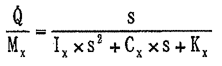
FF 제어부(24)는, 피치 모멘트로부터 피치 레이트까지의 특성을 2차의 진동 모델로서 모델화하고, 전달 함수를 산출하며, 그 역특성을 이용한 제어기이다. 여기서, 피치 운동의 운동 방정식은 하기의 수학식 1로부터 구한다. 단, Q: 피치각, Ix: 피치 관성, Kx: 피치 강성, Cx: 피치 감쇠 계수, Mx: 피치 모멘트이다.The
![]()
![]()
이 수학식 1에 따라 피치 모멘트로부터 피치 레이트까지의 전달 함수는, 하기의 수학식 2가 되고, 이에 따라, 피치 모멘트로부터 피치 레이트까지의 전달 함수는, 하기의 수학식 3으로서 구한다.The transfer function from the pitch moment to the pitch rate in accordance with this equation (1) is given by the following equation (2), whereby the transfer function from the pitch moment to the pitch rate is obtained by the following equation (3).

FB 제어부(26)는 PID 제어기로서, 상기 오차에 따라 목표 피치 모멘트를 출력하도록 구성하여도 좋고, 현대 제어 이론 등으로 구성하여도 좋으며, 특히 제어 법칙에 대하여 한정되지 않는다. 피치 제어부(23)는, 전술한 바와 같이 차연산부(25)에 의해 목표 피치 레이트의 보정값과 실제 피치 레이트의 차를, 목표값과의 오차로서 연산하고, 가산부(27)에서는, FF 제어부(24)와 FB 제어부(26)에서 각각 산출한 목표 피치 모멘트를 가산하며, 그 값을 목표 피치 모멘트로서 목표 감쇠력 산출부(28)에 출력한다.The
즉, 피치 제어부(23)에 있어서의 가산부(27)는, FF 제어부(24)에서 산출한 목표 피치 모멘트와 FB 제어부(26)에서 산출한 목표 피치 모멘트를 가산하여, 그 값을 목표 피치 모멘트(Mp)로서 후단의 목표 감쇠력 산출부(28)에 출력한다. 피치 제어부(23)의 목표 감쇠력 산출부(28)는, 이때의 목표 피치 모멘트가 입력됨으로써, 차체(1)측에서의 롤감을 향상시키기 위한 피치 제어에 따른 목표 감쇠력을 산출한다.That is, the
목표 감쇠력 산출부(28)는, 도 3에 나타내는 바와 같이 목표 피치 모멘트(Mp)가 입력되면, 이에 따라 각 차륜(즉, 좌, 우의 전륜(2), 후륜(3))의 목표 감쇠력을 반분하도록 연산한다. 즉, 목표 감쇠력 산출부(28)의 블록(28A)에서는, 목표 피치 모멘트(Mp)를 4분할하여 각 바퀴에 등배분한다. 다음 블록(28B)에서는, 등배분된 모멘트(Mp/4)를 전륜(2)측의 무게 중심점까지의 거리(lf)로 나눔으로써 우측 전륜(2)의 목표 감쇠력(FFR)을 산출한다. 블록(28C)에서는, 등배분된 모멘트(Mp/4)를 전륜(2)측의 무게 중심점까지의 거리(lf)로 나눔으로써 좌측 전륜(2)의 목표 감쇠력(FFL)을 산출한다.3, when the target pitch moment Mp is input, the target damping
한편, 목표 감쇠력 산출부(28)의 블록(28D)에서는, 전륜(2)측과 후륜(3)측에서 목표 감쇠력을 반대 방향으로 설정하기 위해 「-1」을 곱하고, 다음 블록(28E)에서는, 등배분된 모멘트(Mp/4)를 후륜(3)측의 무게 중심점까지의 거리(lr)로 나눔으로써 우측 후륜(3)의 목표 감쇠력(FRR)을 산출한다. 블록(28F)에서는, 등배분된 모멘트(Mp/4)를 후륜(3)측의 무게 중심점까지의 거리(lr)로 나눔으로써 좌측 후륜(3)의 목표 감쇠력(FRL)을 산출한다.On the other hand, in the
다음에, 본 발명의 타이어 한계 판단 수단에 해당하는 차량 주행 시의 타이어가 상용 영역(선형 영역)으로부터의 한계 영역(비선형 영역)에 달하였는지의 여부를 판단하는 한계 영역 판단부(29)에 대해서 설명한다. 이 한계 영역 판단부(29)는, 차량 모델부(30), 편차 연산부(31), 절대값 연산부(32) 및 제1, 제2 맵 연산부(33, 34)를 포함하여 구성되고, 본 발명의 구성 요건인 차량 운동 판단 수단을 구성하는 것이다.Next, with respect to the marginal region judging section 29 for judging whether or not the tire at the time of vehicle running corresponding to the tire margin judging means of the present invention reaches the marginal region (non-linear region) from the commercial region (linear region) Explain. This limit area determination unit 29 is configured to include a
이 경우, 한계 영역 판단부(29)의 차량 모델부(30)는, 조타각 센서(13)에서 검출한 조타각의 신호(전륜 타각(δf))와 차속 센서(14)에서 검출한 차속(V)의 신호에 기초하여, 하기의 수학식 4에 따른 선형 차량 모델의 요 레이트(γ)를 추정 연산한다. 여기서, V는 차속(m/s), A는 안정 계수(stability factor)(S2/m2), δf는 전륜 타각(rad), L은 휠 베이스(m)이다.In this case, the

편차 연산부(31)는, 실제로 요 레이트 센서(12)에서 검출한 실제 요 레이트와, 차량 모델부(30)에서 추정 연산한 요 레이트(γ)의 차를 연산하고, 그 절대값을 절대값 연산부(32)에서 차(差) 요 레이트(Δγ)로서 산출한다. 제1 맵 연산부(33)는 차 요 레이트(Δγ)에 기초하여 제1 무게 계수(Gr)를 맵 연산하는 것이며, 제1 무게 계수(Gr)는, 도 2 중에 나타내는 바와 같이 차 요 레이트(Δγ)가 작은 때에는, 예컨대 「1」보다 작은 값으로 설정되고, 차 요 레이트(Δγ)가 커지면 점차 증가하여, 예컨대 「1」 또는 「1」보다도 큰 값으로 설정된다.The
제2 맵 연산부(34)는, 차 요 레이트(Δγ)에 기초하여 제2 무게 계수(Gp)를 맵 연산하는 것이며, 제2 무게 계수(Gp)는, 도 2 중에 나타내는 바와 같이 차 요 레이트(Δγ)가 작은 때에는, 예컨대 「1」 또는 「1」보다 큰 값으로 설정되고, 차 요 레이트(Δγ)가 커지면 점차 감소하여, 예컨대 「0」 또는 「0」에 가까운 값으로 설정된다. 즉, 제2 무게 계수(Gp)는, 제1 무게 계수(Gr)가 점차 증대할 때에는, 반대로 점차 작아져 「0」에 근접하는 값으로 설정되고, 제1 무게 계수(Gr)가 점차 감소할 때에는, 예컨대 「1」 또는 이보다도 큰 값으로 설정되는 것이다.The
이에 따라, 한계 영역 판단부(29)는, 차량 모델부(30)에서 추정 연산한 요 레이트(γ)와 실제 요 레이트의 편차인 차 요 레이트(Δγ)가 커졌을 때에는, 차량 주행 시의 타이어가 상용 영역(선형 영역)으로부터 비선형 영역, 즉 한계 영역이 가까운 상태에 있다고 판단하고, 이 경우에는 롤 억제부(18)측에서의 제어에 무게를 부여하도록 제1 무게 계수(Gr)를 크게 하며, 피치 제어부(23)측에서의 제어를 상대적으로 작게 하기 위해, 제2 무게 계수(Gp)를 「0」 또는 「0」에 근접하도록 작게 한다.Accordingly, when the difference yaw rate DELTA gamma, which is the deviation between the yaw rate gamma estimated by the
제1 무게 계수 곱셈부(35)는, 롤 억제부(18)로부터 각 바퀴측의 감쇠력 가변 댐퍼(6, 9)에 출력하는 롤 억제 제어(안정성 향상 제어)를 행하기 위한 목표 감쇠력에 대하여, 상기 제1 무게 계수(Gr)를 곱하고, 안정성 향상용의 목표 감쇠력에 대한 가중을 행하는 것이다. 제2 무게 계수 곱셈부(36)는, 피치 제어부(23)로부터 각 바퀴측의 감쇠력 가변 댐퍼(6, 9)에 출력하는 피치 제어(롤감 향상 제어)를 행하기 위한 목표 감쇠력에 대하여, 상기 제2 무게 계수(Gp)를 곱하고, 롤감 향상용의 목표 감쇠력에 대한 가중을 행하는 것이다.The first weight
이와 같이, 차량 운동 판단 수단을 구성하는 한계 영역 판단부(29)는, 차량 모델부(30)에서 추정한 요 레이트와 실제 요 레이트의 차를, 차 레이트(Δγ)로서 산정하고, 이 차 요 레이트(Δγ)를 각 제어의 무게를 산출하는 제1, 제2 맵 연산부(33, 34)에 입력하여 제1, 제2 무게 계수(Gr, Gp)를 구하며, 제1 무게 계수 곱셈부(35)에서는, 롤 억제부(18)에서 산출한 목표 감쇠력과 제1 무게 계수(Gr)를 곱하고, 타이어의 한계 영역 등에 맞추어 보정한 제1 목표 감쇠력을 산출하며, 제2 무게 계수 곱셈부(36)에서는, 피치 제어부(23)에서 산출한 목표 감쇠력과 제2 무게 계수(Gp)를 곱하고, 마찬가지로 한계 영역 등에 맞추어 보정한 제2 목표 감쇠력을 산출한다. 이에 따라, 제1 목표 감쇠력(안정성 향상 제어)과 제2 목표 감쇠력(롤감 향상 제어)의 제어 비율이 전환된다.In this manner, the marginal area determining unit 29 constituting the vehicle-motion determining means calculates the difference between the yaw rate estimated by the
가산부(37)는, 전술한 바와 같이 타이어의 한계 영역 등에 맞추어 가중하여 보정한 제1 무게 계수 곱셈부(35)에 따른 목표 감쇠력과 제2 무게 계수 곱셈부(36)에 따른 목표 감쇠력을 가산하고, 이것을 최종적인 목표 감쇠력으로서 감쇠력 맵 연산부(38)에 출력한다. 감쇠력 맵 연산부(38)는, 이와 같이 산출한 목표 감쇠력과 상대 속도 추정부(16)에 따른 각 감쇠력 가변 댐퍼(6, 9)의 상대 속도에 따라, 미리 기억해 둔 댐퍼의 특성 맵으로부터 제어 전류의 지령값을 맵 연산에 따라 산출한다.The
다음에, 전류 드라이버(39)는, 감쇠력 맵 연산부(38)로부터 출력된 전류의 지령값에 기초하여 감쇠력 가변 댐퍼(6, 9)의 액츄에이터에 출력하여야 할 목표 감쇠력에 대응한 전류값의 제어를 행하는 것이다. 그리고, 각 차륜(좌, 우의 전륜(2)과 좌, 우의 후륜(3))측의 감쇠력 가변 댐퍼(6, 9)는, 상기 액츄에이터에 공급된 전류값(전류 지령값)에 따라 감쇠력 특성이 하드와 소프트 사이에서 연속적으로, 또는 복수단에서 가변으로 제어된다.Next, the
각 차륜측의 감쇠력 가변 댐퍼(6, 9)는, 예컨대 도 2에 나타내는 롤 레이트 보정부(17), 롤 억제부(18), 제1 무게 계수 곱셈부(35), 가산부(37), 목표 감쇠력 산출부(28) 및 전류 드라이버(39)와 함께, 본 발명의 구성 요건인 안정성 향상 제어 수단을 구성하고 있다. 또한, 각 차륜(좌, 우의 전륜(2), 후륜(3))측의 감쇠력 가변 댐퍼(6, 9)는, 예컨대 도 2에 나타내는 피치 제어부(23), 제2 무게 계수 곱셈부(36), 가산부(37), 감쇠력 맵 연산부(38) 및 전류 드라이버(39)와 함께, 본 발명의 구성 요건인 롤감 향상 제어 수단의 피치 모멘트 발생 수단을 구성하는 것이다.The damping force
본 실시형태에 따른 차체 자세 제어 장치는, 전술한 바와 같은 구성을 갖는 것이며, 다음에, 컨트롤러(15)에 의한 차체(1)의 자세 제어 동작에 대해서 설명한다.The vehicle body posture control device according to the present embodiment has the above-described configuration. Next, the posture control operation of the
각 차륜(좌, 우의 전륜(2)과 좌, 우의 후륜(3))측의 감쇠력 가변 댐퍼(6, 9)와, 컨트롤러(15) 내의 롤 레이트 보정부(17), 롤 억제부(18), 제1 무게 계수 곱셈부(35), 가산부(37), 목표 감쇠력 산출부(28) 및 전류 드라이버(39)로 이루어지는 차량의 안정성 향상 제어 수단은, 롤 레이트 센서(10)에서 검출한 롤 레이트에 대하여 롤 레이트 보정부(17)에서 보정 롤 레이트를 산출하고, 롤 억제부(18)에서는, 롤 억제 제어를 행하기 위해 보정 롤 레이트에 기초하여 각 바퀴측의 감쇠력 가변 댐퍼(6, 9)에 있어서의 목표 감쇠력을 산출한다.The damping force
또한, 컨트롤러(15) 내의 게인 곱셈부(19), 적분부(20), 부호 판별부(21) 및 곱셈부(22)로 이루어지는 목표 피치 레이트 산출 수단은, 차체(1)의 롤 레이트의 크기에 따라 선형 또는 비선형으로 증대하도록 차체(1)의 피치 레이트의 목표값인 목표 피치 레이트를 산출한다. 그리고, 피치 제어부(23)는, 차체(1)측에서의 롤감을 향상시키기 위한 피치 제어에 따른 목표 감쇠력을 산출한다. 이에 따라, 각 차륜(좌, 우의 전륜(2), 후륜(3))측에 마련한 감쇠력 가변 댐퍼(6, 9)의 감쇠력 특성은, 상기 목표 피치 레이트가 되도록 가변으로 제어되고, 차체(1)에 대하여 롤감 향상을 위한 피치 모멘트를 발생시키는 제어를 행한다.The target pitch rate calculating means including the
한편, 한계 영역 판단부(29)는, 차량 모델부(30)에서 추정한 요 레이트와 실제 요 레이트의 차를 차 요 레이트(Δγ)로서 산정하고, 차량의 한계 상태를 차 요 레이트(Δγ)에 의해 판단하는 제어를 행한다. 즉, 이 차 요 레이트(Δγ)를 제1, 제2 맵 연산부(33, 34)에 입력하여 제1, 제2 무게 계수(Gr, Gp)를 구하고, 제1 무게 계수 곱셈부(35)에서는, 롤 억제부(18)에서 산출한 목표 감쇠력과 제1 무게 계수(Gr)를 곱하며, 타이어의 한계 영역에 맞추어 보정한 제1 목표 감쇠력을 산출한다. 또한, 제2 무게 계수 곱셈부(36)에서는, 피치 제어부(23)에서 산출한 목표 감쇠력과 제2 무게 계수(Gp)를 곱하고, 마찬가지로 한계 영역에 맞추어 보정한 제2 목표 감쇠력을 산출한다.On the other hand, the marginal area determining unit 29 calculates the difference between the yaw rate estimated by the
이에 따라, 차량 주행 시의 타이어가 상용 영역인 선형 영역에 있는 동안은, 롤 레이트에 따라 목표 피치 레이트를 산출하는 피치 제어부(23)측의 제어를 우선시키고, 이 목표 피치 레이트가 되도록 각 바퀴측의 목표 감쇠력을 가변으로 제어함으로써, 롤 레이트와 피치 레이트를 비례 관계로 할 수 있다. 이 결과, 코너에 있어서 다이브시키면서 진입하고, 스쿼트 상태에서 코너로부터 빠져나온다고 하는 원활하게 되는 코너링의 자세를 얻을 수 있으며, 롤감이 향상된다.Thus, while the tire during running of the vehicle is in the linear region which is the commercial area, the control on the side of the pitch controller 23 for calculating the target pitch rate is prioritized according to the roll rate, So that the roll rate and the pitch rate can be made proportional to each other. As a result, it is possible to obtain a cornering posture in which the ball enters the corner while diving and smoothly escapes from the corner in the squat state, and the roll feeling is improved.
이에 대하여, 타이어의 노면 그립 상태가 나쁜 한계 영역(즉, 비선형 영역)에서는, 제2 무게 계수 곱셈부(36)에 의해 제2 무게 계수(Gp)를 「0」 또는 이것에 근접하도록 연산하고, 피치 제어부(23)에서 산출한 목표 감쇠력을 제2 무게 계수(Gp)로 작게 하도록 보정한다. 이에 따라, 롤 억제부(18)에서 산출한 목표 감쇠력에 무게를 부여하고, 롤 억제 제어량을 크게 함으로써, 롤 레이트에 비례하여 롤을 억제하도록 감쇠력을 발생시킬 수 있으며, 롤 억제를 적극적으로 행함으로써 차량의 안정성을 향상시킬 수 있다.On the other hand, the second
이렇게 하여, 제1 실시형태에 따르면, 주행 시의 타이어의 상용 영역에서는 롤감 향상에 무게를 두고 제어하며, 한계 영역에서는 롤감보다도 차량의 안정성을 중시하여 롤 억제에 무게를 둠으로써, 차량의 운전 상황에 따라 최적의 제어를 실행하도록 하고 있다. 이에 따라, 종래의 과제였던 한계 영역에서의 차체(1)의 안정성을 향상시킬 수 있다. 또한, 상용 영역에서는 피치와 롤의 거동에 이상적인 관련성을 갖게 할 수 있고, 주행 중의 드라이버 필링(롤감)을 향상시킬 수 있다.Thus, according to the first embodiment, by controlling the weight of the roll area in the commercial area of the tire while driving and by weighting the roll stability by emphasizing the stability of the vehicle more than the rolling area in the limit area, So that the optimum control is carried out. Thus, the stability of the
이와 같이, 차량의 상황에 따라 롤감의 향상과 안정성의 향상을 적절하게 전환하여 실현할 수 있으며, 차량의 승차감과 조종 안정성을 전체적으로 높일 수 있다. 그리고, 상용 영역에서는 차체(1)측의 롤감을 향상시킬 수 있고, 한계 영역에서는 안정성을 중시한 제어를 행할 수 있으며, 양성능을 양립시킬 수 있다. 또한, 이 경우의 제어는, 논리를 전환하는 것은 아니며, 기존의 논리의 게인이나 입력 신호를 크게 하도록 구성함으로써, 양성능의 양립화를 도모할 수 있고, 제어 도중에서의 불연속인 전환이 없으며, 원활한 제어를 실현할 수 있다.As described above, according to the situation of the vehicle, improvement in rolling feeling and improvement in stability can be appropriately switched and realized, and ride comfort and steering stability of the vehicle can be improved as a whole. In the commercial area, the roll feeling on the side of the
또한, 상기 제1 실시형태에서는, 롤 레이트 센서(10)에서 롤 레이트를 검출하고, 피치 레이트는 피치 레이트 센서(11)를 이용하여 검출하는 경우를 예로 들어 설명하였다. 그러나, 본 발명은 이에 한정되지 않고, 예컨대 차체에 부착한 상, 하 방향의 가속도 센서를 이용하여, 롤 레이트, 피치 레이트를 산출하여도 좋다. 또한, 댐퍼의 상대 속도는 차 높이 센서의 미분값에 따라 구하는 구성으로 하여도 좋고, 예컨대 스프링 하측과 스프링 상측에 각각 부착한 상, 하 방향의 가속도 센서에 따른 검출값으로부터 상대 가속도를 산출하며, 이 값을 적분함으로써 산출하여도 좋고, 특별히 산출 방법을 한정할 필요는 없는 것이다.In the first embodiment, the case where the roll rate is detected by the
다음에, 도 4는 본 발명의 제2 실시형태를 나타내며, 제2 실시형태의 특징은, 조타각과 차속으로부터 차량 모델을 이용한 횡가속도와 요 레이트를 산출하고, 롤 레이트 센서나 피치 레이트 센서를 사용하지 않고 차체의 자세 제어를 행하는 구성으로 한 것에 있다. 또한, 제2 실시형태에서는, 전술한 제1 실시형태와 동일한 구성 요소에 동일한 부호를 붙이고, 그 설명을 생략하는 것으로 한다.Next, Fig. 4 shows a second embodiment of the present invention. A feature of the second embodiment is that the lateral acceleration and the yaw rate using the vehicle model are calculated from the steering angle and the vehicle speed, and a roll rate sensor or a pitch rate sensor The posture of the vehicle body is controlled without performing the posture control. In the second embodiment, the same constituent elements as those of the first embodiment described above are denoted by the same reference numerals, and a description thereof will be omitted.
도면 중, 도면 부호 41은 제2 실시형태에서 채용한 제어 수단으로서의 컨트롤러이며, 상기 컨트롤러(41)는, 입력측이 요 레이트 센서(12), 조타각 센서(13) 및 차속 센서(14) 등에 접속되고, 출력측이 좌, 우의 전륜(2)측에 마련한 감쇠력 가변 댐퍼(6)와 좌, 우의 후륜(3)측에 마련한 감쇠력 가변 댐퍼(9)의 액츄에이터(도시하지 않음) 등에 접속되어 있다.In the figure, reference numeral 41 denotes a controller as control means employed in the second embodiment. The controller 41 controls the input side to be connected to the
컨트롤러(41)는, 도 4에 나타내는 바와 같이, 차량 모델부(42), 롤용 게인 곱셈부(43), 제1 필터부(44), 제1 미분부(45), 절대값 연산부(46), 제2 미분부(47), 피치용 게인 곱셈부(48), 피치 제어부(49) 및 제2 필터부(50) 등을 포함하여 구성되어 있다. 또한, 컨트롤러(41)는, 제1 실시형태에서 서술한 컨트롤러(15)와 마찬가지로, 상대 속도 추정부(16), 롤 레이트 보정부(17), 롤 억제부(18), 편차 연산부(31), 절대값 연산부(32), 제1, 제2 맵 연산부(33, 34), 제1, 제2 무게 계수 곱셈부(35, 36), 가산부(37), 감쇠력 맵 연산부(38) 및 전류 드라이버(39) 등을 포함하여 구성되어 있다.4, the controller 41 includes a
이 경우, 차량 모델부(42)는, 제2 필터부(50), 편차 연산부(31), 절대값 연산부(32) 및 제1, 제2 맵 연산부(33, 34) 등과 함께 주행 상태 판단부(51)를 구성하고, 이 주행 상태 판단부(51)는, 본 발명의 구성 요건인 차량 운동 판단 수단을 구성하는 것이다.In this case, the
컨트롤러(41)는, 조타각 센서(13)에서 검출한 조타각의 신호와 차속 센서(14)에서 검출한 차속의 신호에 기초하여, 차량 모델부(42)에서 하기와 같이 횡가속도(αy)를 추정하여 연산한다. 이 횡가속도(αy)는, 차량의 선형 모델을 가정하고, 동작 특성을 무시하면, 수학식 5의 식으로 구할 수 있다. 단, V는 차속(m/s), A는 안정 계수(S2/m2), δf는 전륜 타각(rad), L은 휠 베이스(m)이다.The controller 41 calculates the lateral acceleration? Y in the

이와 같이 산출한 횡가속도(αy)에 대하여, 롤용 게인 곱셈부(43)에서는, 미리 결정할 수 있었던 게인(「Kay2roll」)[deg/(m/s2)]을 곱함으로써 롤각을 산출한다. 이 경우의 게인은, 횡가속도(αy)에 대한 롤각의 관계를 (롤각/횡가속도 게인)으로서 설정한 것이다. 그러나, 게인 곱셈부(43)로부터 출력되는 롤각의 신호는, 핸들이 조타되고 나서 차체(1)에 롤각이 발생할 때까지의 동작 특성을 무시한 신호가 된다. 이 때문에, 제1 필터부(44)는, 이 경우의 동작 특성을 근사한 로우패스 필터(「LPF」)에 의해 다이나믹스를 재현하는 것이다.In, for the transfer
또한, 차량 모델부(42)는, 제1 실시형태에서 서술한 차량 모델부(30)와 마찬가지로, 조타각 센서(13)와 차속 센서(14)로부터의 검출 신호에 기초하여, 전술한 수학식 4에 따른 선형 차량 모델의 요 레이트(γ)를 추정 연산한다. 제2 필터부(50)는, 차량 모델부(42)로부터 출력되는 신호(요 레이트)가 이대로는 동작 특성을 무시한 형태가 되기 때문에, 로우패스 필터(「LPF」)에 의해 추정 요 레이트의 동작 특성을 근사시키는 것이다.The
다음에, 제1 미분부(45)는, 제1 필터부(44)로부터 출력되는 추정 롤각을 미분하여, 롤 레이트를 산출한다. 제1 미분부(45)에서 산출한 롤 레이트가 큰 경우에는 조타 속도가 빠르고, 롤 오버 발생의 가능성이 높다. 이 때문에, 롤 레이트 보정부(17)에서는, 산출값(롤 레이트)이 큰 경우에 안정성을 중시하여 외관상의 롤 레이트를 크게 하는 비선형 게인을 이용하여 보정 롤 레이트를 산출한다. 그리고, 롤 억제부(18)에서는, 보정 롤 레이트에 기초하여 차체(1)측의 롤을 억제하도록 각 바퀴측에서의 목표 감쇠력을 산출한다.Next, the first differentiating
다음에, 롤감을 향상시키기 위한 피치 제어부(49)에 있어서는, 우선, 절대값 연산부(46)에서 추정 롤각의 절대값을 구하고, 이것을 제2 미분부(47)에서 미분한 후에, 피치용 게인 곱셈부(48)에서 게인(「Kpitch」)을 곱하여 목표 피치 레이트를 산출한다. 피치 제어부(49)는, 산출한 목표 피치 레이트로부터 FF 제어에 의해 피치 방향의 다이나믹스를 고려한 뒤에, 목표 피치 레이트를 발생시키는데 필요한 각 바퀴의 목표 감쇠력을 산출한다.Next, in the
다음에, 차량 모델부(42), 제2 필터부(50), 편차 연산부(31), 절대값 연산부(32) 및 제1, 제2 맵 연산부(33, 34) 등으로 이루어지는 주행 상태 판단부(51)는, 제1 실시형태에서 서술한 한계 영역 판단부(29)와 마찬가지로, 편차 연산부(31) 및 절대값 연산부(32)에서 구한 차 요 레이트(Δγ)를 제1, 제2 맵 연산부(33, 34)에 입력하여 제1, 제2 무게 계수(Gr, Gp)를 구한다.Next, a traveling
그리고, 제1 무게 계수 곱셈부(35)에서는, 롤 억제부(18)에서 산출한 목표 감쇠력과 제1 무게 계수(Gr)를 곱하고, 타이어의 한계 영역에 맞추어 보정한 제1 목표 감쇠력을 산출한다. 또한, 제2 무게 계수 곱셈부(36)에서는, 피치 제어부(23)에서 산출한 목표 감쇠력과 제2 무게 계수(Gp)를 곱하고, 마찬가지로 한계 영역에 맞추어 보정한 제2 목표 감쇠력을 산출한다. 이에 따라, 롤 억제 제어와 피치 제어의 제어량을 차 요 레이트(Δγ)에 따라 조정하는 것이다.Then, the first
또한, 상대 속도 추정부(16)에서는, 미분부(45)에서 산출한 롤 레이트와 차량 제원(諸元)으로부터 기하학적 관계를 이용하여 각 바퀴의 상대 속도를 추정한다. 가산부(37)에서는, 이와 같이 산출한 롤 억제 제어량과 피치 제어량을 합쳐 각 바퀴의 목표 감쇠력을 산정한다. 이 목표 감쇠력과 추정한 상대 속도에 기초하여, 감쇠력 맵 연산부(38)에서는, 미리 기억해 둔 감쇠력 특성(감쇠력-전류값-상대 속도)으로부터 지령 전류값을 산출한다. 전류 드라이버(39)는, 산출한 전류값에 해당하는 전류를 감쇠력 가변 댐퍼(6, 9)의 액츄에이터에 출력하고, 각각의 감쇠력 특성을 가변으로 제어한다.The relative
이렇게 하여, 이와 같이 구성되는 제2 실시형태에서도, 제1 실시형태와 마찬가지로, 차량의 상황에 따라 롤감의 향상과 안정성의 향상을 적절히 행함으로써, 차량의 승차감과 조종 안정성을 전체적으로 높일 수 있다. 특히, 제2 실시형태에서는, 롤 레이트 센서나 피치 레이트 센서를 사용하지 않고, 요 레이트 센서(12), 조타각 센서(13) 및 차속 센서(14)로부터의 검출 신호에만 기초하여 차체(1)의 자세 제어를 실시할 수 있다.Thus, in the second embodiment configured as described above, similarly to the first embodiment, the ride feeling and the steering stability of the vehicle can be improved as a whole by appropriately performing the rolling feeling improvement and the stability improvement according to the situation of the vehicle. Particularly, in the second embodiment, the
이에 따라, 센서 절약화를 도모할 수 있으며, 비용을 저감하고, 시스템을 간소화할 수 있다. 또한, 요 레이트 센서(12)에서 검출한 신호에 기초 컨트롤러(41)에서 연산한 감쇠력 가변 댐퍼(6, 9)에 대한 지령 전류에 의해 제어를 행하기 때문에, 롤감의 향상과 한계 영역에서의 안정성 개선을 실현 가능하게 된다.Thus, the sensor can be saved, the cost can be reduced, and the system can be simplified. In addition, since the signal detected by the
다음에, 도 5 및 도 6은 본 발명의 제3 실시형태를 나타내고, 제3 실시형태의 특징은, 차체의 자세 제어를 행하는 액츄에이터가 세미 액티브 서스펜션(예컨대, 감쇠력 조정식의 유압 완충기)이 아니며, 스스로 추력을 발생 가능한 액티브 서스펜션을 이용하는 구성으로 한 것에 있다. 또한, 제3 실시형태에서는, 전술한 제1 실시형태와 동일한 구성 요소에 동일한 부호를 붙이고, 그 설명을 생략하는 것으로 한다.Next, Figs. 5 and 6 show a third embodiment of the present invention, and a feature of the third embodiment is that the actuator for performing the attitude control of the vehicle body is not a semi-active suspension (for example, a damping force adjusting type hydraulic shock absorber) And an active suspension capable of generating thrust by itself is used. In the third embodiment, the same constituent elements as those of the first embodiment described above are denoted by the same reference numerals, and a description thereof will be omitted.
도면 중, 도면 부호 71은 본 실시형태에서 채용한 제어 수단으로서의 컨트롤러이며, 상기 컨트롤러(71)는, 제1 실시형태에서 서술한 컨트롤러(15)와 거의 동일하게 구성되고, 입력측이 롤 레이트 센서(10), 피치 레이트 센서(11), 요 레이트 센서(12), 조타각 센서(13) 및 차속 센서(14) 등에 접속되어 있다. 또한, 컨트롤러(71)의 입력측에는 복수의 차 높이 센서(72)가 접속되고, 이들 차 높이 센서(72)는, 좌, 우의 전륜(2)측과 좌, 우의 후륜(3)측에서 각각 개별로 차 높이를 검출하는 것이다.In the drawing, reference numeral 71 denotes a controller as a control means employed in the present embodiment. The controller 71 is configured substantially the same as the
또한, 이 경우의 컨트롤러(71)는, 출력측이 스스로 추력을 발생 가능한 액티브 서스펜션(후술하는 전자 댐퍼(79)) 등에 접속되어 있는 점에서, 제1 실시형태와는 다르다. 여기서, 컨트롤러(71)는, 롤각 산출부(73), FB 제어부(74), 게인 곱셈부(19), 부호 판별부(21), 곱셈부(22), 피치 제어부(75), 한계 영역 판단부(29), 제1, 제2 무게 계수 곱셈부(76, 77) 및 각 바퀴의 전자 댐퍼 제어량 산출부(78)를 포함하여 구성되고, 이 중 게인 곱셈부(19), 부호 판별부(21), 곱셈부(22) 및 한계 영역 판단부(29)는, 제1 실시형태와 동일하게 구성되어 있다.The controller 71 in this case is different from the first embodiment in that the output side is connected to an active suspension (an
도면 부호 79는 차량의 각 바퀴측에 마련되는 복수(4개)의 전자 댐퍼이며, 이 전자 댐퍼(79)는, 예컨대 좌, 우의 전륜(2)과 좌, 우의 후륜(3)측에 각각 마련된 액티브 서스펜션에 의해 구성되며, 각 차륜측에서 차체(1)를 상, 하 방향으로 승강시키는 것과 같은 추력을, 각 바퀴의 전자 댐퍼 제어량 산출부(78)로부터의 제어 신호에 따라 발생하는 것이다.
컨트롤러(71)의 롤각 산출부(73)는, 각 차 높이 센서(72)로부터의 차 높이 신호에 기초하여 차체(1)의 롤각을 연산에 의해 구한다. 피드백 제어를 행하는 FB 제어부(74)는, 롤 레이트 센서(10)로부터의 롤 레이트와 롤각 산출부(73)에 의한 롤각에 기초하여, 롤 억제 제어를 행하기 위한 목표 롤 모멘트를 산출하고, 이것을 제1 무게 계수 곱셈부(76)에 대하여 출력한다.The roll
컨트롤러(71)의 피치 제어부(75)는, 제1 실시형태에서 서술한 피치 제어부(23)와 거의 마찬가지로, FF 제어부(24), 차연산부(25), FB 제어부(26), 가산부(27)를 포함하여 구성되어 있다. 그리고, 피치 제어부(75)는, FF 제어부(24)에서 산출한 목표 피치 모멘트와 FB 제어부(26)에서 산출한 목표 피치 모멘트를 가산부(27)에서 가산하고, 이것을 롤감 향상용의 목표 피치 모멘트로서 제2 무게 계수 곱셈부(77)에 출력한다.The pitch control section 75 of the controller 71 controls the
제1 무게 계수 곱셈부(76)는, FB 제어부(74)로부터 각 바퀴의 전자 댐퍼 제어량 산출부(78)에 출력하는 롤 억제 제어(안정성 향상 제어)용의 목표 롤 모멘트에 대하여, 제1 맵 연산부(33)로부터 출력되는 제1 무게 계수(Gr)를 곱하고, 안정성 향상용의 목표 롤 모멘트에 대한 가중을 행한다. 제2 무게 계수 곱셈부(77)는, 피치 제어부(75)로부터 각 바퀴의 전자 댐퍼 제어량 산출부(78)에 출력하는 피치 제어(롤감 향상 제어)용의 목표 피치 모멘트에 대하여, 제2 맵 연산부(34)로부터 출력되는 제2 무게 계수(Gp)를 곱하고, 롤감 향상용의 목표 피치 모멘트에 대한 가중을 행하는 것이다.The first weight
다음에, 각 바퀴의 전자 댐퍼 제어량 산출부(78)는, 도 6에 나타내는 바와 같이, 블록(78A∼78N)을 포함하여 구성되고, 각 차륜(즉, 좌, 우의 전륜(2)과 좌, 우의 후륜(3))에 대하여 목표 피치 모멘트와 목표 롤 모멘트를 반분하기 위한 연산을 실행한다. 즉, 각 바퀴의 전자 댐퍼 제어량 산출부(78)는, 각 차륜측에 반분된 목표 피치 모멘트와 목표 롤 모멘트에 대응하는 목표 추력(FR, FL, RR, RL)을, 각 차륜측의 전자 댐퍼(79)에서 발생할 수 있도록 전자 댐퍼 제어량을 산출하고, 산출한 제어량(목표 추력(FR, FL, RR, RL))분의 제어 신호를 각 전자 댐퍼(79)에 개별로 출력하는 것이다.6, the electronic damper control
여기서, 전자 댐퍼 제어량 산출부(78)의 블록(78A)에서는, 목표 피치 모멘트(Mp)를 4분할하여 각 바퀴에 등배분한다. 다음의 블록(78B)에서는, 등배분된 피치 모멘트(Mp/4)를 우측 전륜(2)측의 무게 중심점까지의 거리(lf)로 나눈다. 블록(78C)에서는, 목표 롤 모멘트(Mr)를 4분할하여 각 바퀴에 등배분한다. 다음의 블록(78D)에서는, 등배분된 롤모멘트(Mr/4)를 트레드의 절반(lwf/2)으로 나눈다. 그리고, 연산부(78E)는, 블록(78B)으로부터의 출력값(Mp/4lf)과 블록(78D)으로부터의 출력값(Mr/2lwf)을 가산하여 우측 전륜(2)측에 있어서의 목표 추력(FR)을 구한다.Here, in the
또한, 다음 블록(78F)에서는, 등배분된 피치 모멘트(Mp/4)를 좌측 전륜(2)측의 무게 중심점까지의 거리(lf)로 나눈다. 블록(78G)에서는, 등배분된 롤모멘트(Mr/4)를 트레드의 절반(lwf/2)으로 나눈다. 그리고, 연산부(78H)는, 블록(78F)으로부터의 출력값(Mp/4lf)에 대하여 블록(78G)으로부터의 출력값(Mr/2lwf)을 감산하여 좌측 전륜(2)측에 있어서의 목표 추력(FL)을 구한다.In the
한편, 전자 댐퍼 제어량 산출부(78)의 블록(78I)에서는, 등배분된 피치 모멘트(Mp/4)를 우측 후륜(3)측의 무게 중심점까지의 거리(lr)로 나눈다. 블록(78J)에서는, 등배분된 롤모멘트(Mr/4)를 트레드의 절반(lwr/2)으로 나눈다. 그리고, 연산부(78K)는, 블록(78J)으로부터의 출력값(Mr/2lwr)에 대하여 블록(78I)으로부터의 출력값(Mp/4lr)을 감산함으로써 우측 후륜(3)의 목표 추력(RR)을 산출한다.On the other hand, the block 78I of the electronic damper control
또한, 블록(78L)에서는, 등배분된 피치 모멘트(Mp/4)를 우측 후륜(3)측의 무게 중심점까지의 거리(lr)로 나눈다. 블록(78M)에서는, 등배분된 롤모멘트(Mr/4)를 트레드의 절반(lwr/2)으로 나눈다. 그리고, 연산부(78N)는, 블록(78L)으로부터의 출력값(Mp/4lr)과 블록(78M)으로부터의 출력값(Mr/2lwr)을 가산하여 부호를 마이너스로 설정함으로써 좌측 후륜(3)측의 목표 추력(RL)을 산출한다.In the
이렇게 하여, 이와 같이 구성되는 제3 실시형태에서도, 제1, 제2 무게 계수 곱셈부(76, 77)에서 목표 롤 모멘트와 목표 피치 모멘트에 대하여 가중을 행함으로써, 제1 실시형태와 마찬가지로, 차량의 상황에 따라 롤감의 향상과 안정성의 향상을 적절히 행할 수 있고, 차량의 승차감과 조종 안정성을 전체적으로 높일 수 있다.Thus, in the third embodiment configured as described above, by weighting the target roll moment and the target pitch moment by the first and second
특히, 제3 실시형태에서는, 전자 댐퍼 제어량 산출부(78)에서 각 차륜측의 목표 추력(FR, FL, RR, RL)을 산출하고, 그 목표값에 따라 전자 댐퍼(79)(액티브 서스펜션)에 추력을 발생시킴으로써, 롤 레이트에 비례한 피치 레이트를 발생시킬 수 있으며, 차체(1)의 회전축을 안정화시켜, 롤감의 향상을 도모할 수 있는데다가, 안정성의 향상화도 도모할 수 있다.Particularly, in the third embodiment, the electronic damper control
또한, 상기 제3 실시형태에서는, 도 6에 나타내는 전자 댐퍼 제어량 산출부(78)의 블록(78A, 78C)에서 목표 롤 모멘트와 목표 피치 모멘트를 각 바퀴에 등배분하는 경우를 예로 들어 설명하였다. 그러나, 본 발명은 이에 한정되는 것이 아니며, 예컨대 롤 모멘트와 피치 모멘트의 평형식으로부터, 이 식을 만족하는 각 바퀴 제어량을 구하는 구성으로 하여도 좋은 것이다.In the third embodiment, the target roll moment and the target pitch moment are allotted to the wheels in the
다음에, 도 7 및 도 8은 본 발명의 제4 실시형태를 나타내고, 제4 실시형태의 특징은, 예컨대 서스펜션에 의한 차체의 자세 변화가 아니라, 엔진과 브레이크를 이용한 차량의 가·감속 제어에 의해 차체의 자세 변화, 피치 거동을 발생시키는 구성으로 한 것에 있다. 또한, 제4 실시형태에서는, 전술한 제1 실시형태와 동일한 구성 요소에 동일한 부호를 붙이고, 그 설명을 생략하는 것으로 한다.Next, Figs. 7 and 8 show a fourth embodiment of the present invention. A feature of the fourth embodiment is that it is possible to control the acceleration / deceleration control of the vehicle using the engine and the brake instead of the posture change of the vehicle body, And changes the posture of the vehicle body and causes pitch behavior. In the fourth embodiment, the same constituent elements as those of the first embodiment described above are denoted by the same reference numerals, and a description thereof will be omitted.
도면 중, 도면 부호 81은 본 실시형태에서 채용한 제어 수단으로서의 컨트롤러이며, 상기 컨트롤러(81)는, 제1 실시형태에서 서술한 컨트롤러(15)와 거의 동일하게 구성되고, 입력측이 롤 레이트 센서(10), 피치 레이트 센서(11), 요 레이트 센서(12), 조타각 센서(13) 및 차속 센서(14) 등에 접속되어 있다. 그러나, 이 경우의 컨트롤러(81)는, 그 출력측이 차량의 엔진 및 브레이크를 제어하는 후술하는 구동력 제어부(87)에 접속되어 있는 점에서, 제1 실시형태와는 다르다.In the drawing, reference numeral 81 denotes a controller as a control means employed in the present embodiment. The controller 81 is configured substantially the same as the
여기서, 컨트롤러(81)는, 게인 곱셈부(19), 적분부(20), 부호 판별부(21), 곱셈부(22), 피치 제어부(82), 한계 영역 판단부(84), 무게 계수 곱셈부(85) 및 가·감속 지령 산출부(86) 등을 포함하여 구성되고, 이 중 게인 곱셈부(19), 적분부(20), 부호 판별부(21) 및 곱셈부(22)는, 제1 실시형태와 동일하게 구성되어 있다.Here, the controller 81 includes a
피치 제어부(82)는, 제1 실시형태에서 서술한 피치 제어부(23)와 거의 마찬가지로, FF 제어부(24), 차연산부(25), FB 제어부(26) 및 가산부(27)를 포함하여 구성되어 있다. 그러나, 이 경우의 피치 제어부(82)는, 가산부(27)로부터의 출력 신호를 후술하는 구동력 제어부(87)에 대응한 목표 피치 모멘트로서 산출하는 목표 피치 모멘트 산출부(83)를 갖고 있는 점에서 제1 실시형태와는 다르다.The pitch control section 82 includes the
한계 영역 판단부(84)는, 제1 실시형태에서 서술한 한계 영역 판단부(29)와 마찬가지로, 차량 모델부(30), 편차 연산부(31), 절대값 연산부(32) 및 맵 연산부(34)를 포함하여 구성되어 있다. 그러나, 이 경우의 한계 영역 판단부(84)는, 제1 맵 연산부(33)(도 2 참조)에 해당하는 구성이 폐지되어 있는 점에서 제1 실시형태와는 상위하고 있다.Similar to the marginal area determination unit 29 described in the first embodiment, the marginal area determination unit 84 includes a
무게 계수 곱셈부(85)는, 제1 실시형태에서 서술한 제2 무게 계수 곱셈부(36)와 거의 동일한 구성이며, 맵 연산부(34)로부터 출력되는 무게 계수(Gp)를, 피치 제어부(82)의 목표 피치 모멘트 산출부(83)로부터 출력되는 목표 피치 모멘트에 대하여 곱한다. 이에 따라 무게 계수 곱셈부(85)는, 구동력 제어부(87)에 출력하는 피치 제어를 행하기 위한 목표 피치 모멘트, 즉 롤감 향상용의 목표 피치 모멘트에 대한 가중을 행한다. 이 때문에, 피치 제어부(82)에서 산출한 목표 피치 모멘트는, 무게 계수(Gp)를 곱함으로써 차량의 한계 정도에 따라 작게 설정되고, 한계 영역에서는 안정성을 중시하는 제어가 행해진다.The weight
가·감속 지령 산출부(86)는, 무게 계수 곱셈부(85)에서 부가된 목표 피치 모멘트에 대하여 도 8에 나타내는 것과 같은 연산 처리를 행하고, 구동력 제어부(87)에 대하여 가감속 지령을 출력한다. 가·감속 지령 산출부(86)는, 도 8에 나타내는 바와 같이 제1 블록(86A)에서 차체(1)의 스프링 상측 무게 중심 높이(h)(m)에 의해 목표 피치 모멘트(Mp)(Nm)를 나누고, 이에 따라 목표 관성력(N)을 산정한다. 제2 블록(86B)에서는, 이 목표 관성력을 차체(1)의 질량(m)(㎏)으로 나누고, 이에 따라 목표 전, 후 가속도를 구하며, 이 목표 전, 후 가속도를 가·감속 지령으로서 산출한다.The acceleration / deceleration
구동력 제어부(87)는, 이와 같이 하여 산출한 가·감속 지령을 차량의 엔진 또는 전기 모터 등의 구동 수단과, 브레이크(모두 도시하지 않음)에 출력하고, 엔진과 브레이크를 각각 제어함으로써, 통상 영역에서는 롤 레이트에 비례한 피치 레이트를 발생시킴으로써 차체(1)의 회전축을 안정화시키고, 롤감의 향상화를 도모할 수 있다. 또한, 한계 영역에서는, 안정성을 중시하여 롤감 향상을 위한 제어를 작게 함으로써, 주행 차량의 안정성을 향상시킬 수 있다.The drive
이렇게 하여, 이와 같이 구성되는 제4 실시형태에서도, 제1 실시형태와 마찬가지로, 차량의 상황에 따라 롤감의 향상과 안정성의 향상을 적절히 행함으로써, 차량의 승차감과 조종 안정성을 전체적으로 높일 수 있다. 특히, 제4 실시형태에서는, 차량의 한계 정도에 따라 롤감을 향상시키기 위해 행하고 있는 가·감속에 의한 피치 제어의 제어량을 조정함으로써, 한계 영역에 있어서는 롤감 제어를 작게 함으로써 타이어에 부가되는 부하를 저감하고, 안정성을 중시하는 가·감속 제어를 할 수 있다.Thus, in the fourth embodiment configured as described above, similarly to the first embodiment, the ride feeling and the steering stability of the vehicle can be improved as a whole by appropriately performing the rolling feeling improvement and the stability improvement according to the situation of the vehicle. Particularly, in the fourth embodiment, by controlling the control amount of the pitch control by the acceleration / deceleration performed to improve the roll feeling in accordance with the limit of the vehicle, the load applied to the tire can be reduced And deceleration control that emphasizes stability is possible.
또한, 상기 제1∼제3 실시형태에서는, 차량 주행 시의 타이어가 한계 영역에 있는지의 여부를 실제 요 레이트와 추정 요 레이트의 차에 따라 판단하고, 롤감을 향상하는 피치 제어와 안정성을 향상하는 롤 억제 제어의 제어 비율을 변경하는 경우를 예로 들어 설명하였다. 그러나, 본 발명은 이에 한정되는 것이 아니며, 그 후의 타이어가 한계 영역에 달하는 것을 추정할 수 있는 경우(한계 상태라고 판단하였을 때)는, 미리, 롤감을 향상하는 피치 제어로부터 안정성을 향상하는 롤 억제 제어의 제어 비율을 크게 하는 제어를 행하여도 좋다. 이 추정되는 조건을 하기의 표 1에 나타낸다. 이 표 1에 나타내는 조건이, 본 발명의 차량 운동 판단 수단의 타이어 한계 판단 수단에 해당한다. 구체적으로는 표 1에 나타내는 바와 같이, 미리 결정된 임계값(예컨대, 시속 100 ㎞/h)을 넘어 차속을 높이는 것과 같은 경우에는, 코너에 들어간 경우에 타이어가 한계 영역에 도달하기 쉬운 상태가 되기 때문에, 미리 안정성을 중시하기 위해 롤 억제 제어의 제어량을 크게 하고, 피치 제어의 제어량을 작게 하도록 하여도 좋다. 더욱, 이에 한정되지 않고, 안정성을 중시하고자 하는 경우에는 각 제어량을 조정하며, 차량 상태에 따라 각 제어 게인을 변경함으로써 롤감의 향상과 안정성의 향상을 양립시키는 구성으로 하여도 좋다.In the first to third embodiments, whether or not the tire at the time of driving the vehicle is in the limit region is determined according to the difference between the actual yaw rate and the estimated yaw rate, and pitch control for improving roll feeling and stability The case where the control ratio of the roll restraining control is changed is described as an example. However, the present invention is not limited to this. When it is possible to estimate that the subsequent tire reaches the limit region (when it is determined that the tire is in the limit state), it is necessary to perform roll control Control for increasing the control ratio of the control may be performed. The estimated conditions are shown in Table 1 below. The conditions shown in Table 1 correspond to the tire limit determination means of the vehicle motion determination means of the present invention. Specifically, as shown in Table 1, when the vehicle speed is increased beyond a predetermined threshold value (for example, 100 km / h), the tire is in a state where it is likely to reach the limit region when entering the corner , The control amount of the roll restraining control may be increased and the control amount of the pitch control may be made smaller in order to attach importance to stability in advance. Furthermore, when the stability is to be emphasized, the control amount may be adjusted and the control gain may be changed according to the vehicle condition to improve the rolling feeling and the stability.

또한, 제1, 제3 실시형태에서는, 롤 레이트와 피치 레이트를 각각 센서를 이용하여 검출하는 경우를 예로 들어 설명하였다. 그러나, 본 발명은 이에 한정되는 것이 아니며, 예컨대 차체에 부착한 3개 이상의 상, 하 방향 가속도 센서를 이용하여 롤 레이트와 피치 레이트를 산출하여도 좋다.In the first and third embodiments, the roll rate and the pitch rate are detected by using sensors, respectively. However, the present invention is not limited to this. For example, the roll rate and the pitch rate may be calculated using three or more acceleration sensors attached to the vehicle body.
또한, 제1, 제2 실시형태에서 이용하고 있는 상대 속도는, 차 높이 센서의 미분값이어도 좋고, 예컨대 스프링 하측의 가속도 센서와 스프링 상측의 가속도 센서의 검출값으로부터 상대 가속도를 산출하며, 이 값을 적분함으로써 산출하여도 좋다. 또한, 편평한 노면이면, 스프링 하측의 움직임이 거의 제로라고 가정할 수 있기 때문에, 스프링 상측의 가속도 센서의 검출값을 적분한 스프링 상측 속도를 상대 속도로 하여도 좋다. 또한, 제2 실시형태에서는, 조타각과 차속으로부터 추정한 횡가속도를 이용하였지만, 횡가속도 센서의 값을 이용하여도 좋다. 특히, 그 외의 신호에 대해서도, 그 산출 방법이 한정되는 것이 아니다.The relative speed used in the first and second embodiments may be a differential value of the vehicle height sensor. For example, the relative acceleration may be calculated from the acceleration sensor on the lower side of the spring and the acceleration sensor on the upper side of the spring, May be calculated. Further, in the case of a flat road surface, since the movement of the lower side of the spring can be assumed to be substantially zero, the upper side speed of the spring integrated with the detection value of the acceleration sensor on the upper side of the spring may be set as the relative speed. In the second embodiment, the lateral acceleration estimated from the steering angle and vehicle speed is used, but the value of the lateral acceleration sensor may also be used. Particularly, the calculation method for other signals is not limited.
다음에, 상기 실시형태에 포함되는 발명에 대해서 기재한다. 즉, 본 발명에 따르면, 차량 운동 판단 수단은, 차량 운동 상태에 따라 타이어가 미끄러지기 시작하는 한계 상태인지의 여부를 판단하는 타이어 한계 판단 수단을 가지고, 상기 타이어 한계 판단 수단이 한계 상태라고 판단하였을 때는, 상기 안정성 향상 제어 수단에 의한 제어 비율을 강하게 하며, 상기 타이어 한계 판단 수단이 한계 상태라고 판단하지 않은 때에는, 상기 한계 상태라고 판단하였을 때보다도 상기 롤감 향상 제어 수단에 의한 제어 비율을 강하게 하는 구성으로 하고 있다. 또한, 상기 타이어 한계 판단 수단은, 타이어의 코너링 파워가 선형 영역으로부터 비선형 영역으로 되는지의 여부를 판단하는 영역 판단 수단을 구비하고, 상기 영역 판단 수단에 의해 상기 선형 영역이라고 판단하였을 때에는, 상기 비선형 영역일 때보다도 상기 롤감 향상 제어 수단에 의한 제어 비율을 강하게 하며, 상기 영역 판단 수단에 의해 상기 비선형 영역으로 된다고 판단하였을 때에는, 상기 선형 영역일 때보다도 상기 안정성 향상 제어 수단에 의한 제어 비율을 강하게 하는 구성으로 하고 있다. 이에 따라, 차량의 주행 상황 등에 따라 롤감의 향상과 안정성의 향상을 적절하게 행할 수 있고, 차량의 승차감과 조종 안정성을 전체적으로 높일 수 있다.Next, the invention included in the above embodiment will be described. That is, according to the present invention, the vehicle-motion determining means includes a tire-limit determining means for determining whether or not the tire starts to slip in accordance with the vehicle motion state, and when the tire- , The control ratio by the stability improvement control means is strengthened and when the tire margin determination means does not determine the limit state, the control ratio by the rolling feeling improvement control means is made stronger than when it is determined that the limit state . The tire limit determining means includes an area determining means for determining whether or not the cornering power of the tire changes from a linear region to a non-linear region. When the region determining means determines that the linear region is the non-linear region, , The control ratio by the roll improvement control means is made stronger than when the linear region is determined to be the nonlinear region by the region determination means and the control ratio by the stability improvement control means is made stronger . As a result, it is possible to appropriately improve the rolling feeling and the stability in accordance with the running condition of the vehicle and the like, and the riding comfort and the steering stability of the vehicle as a whole can be enhanced.
또한, 본 발명에 따르면, 상기 타이어 한계 판단 수단은, 차속이 미리 결정된 임계값을 넘었을 때에 상기 안정성 향상 제어 수단의 제어 비율을 강하게 하는 구성으로 하고 있다. 이에 따라, 주행 속도가 상기 임계값을 넘는 것과 같은 경우에는, 안정성 향상 제어를 우선시키고, 조종 안정성을 높일 수 있다.Further, according to the present invention, the tire limit determination means is configured to increase the control ratio of the stability improvement control means when the vehicle speed exceeds a predetermined threshold value. Thus, when the running speed exceeds the threshold value, the stability improvement control is given priority and the steering stability can be enhanced.
상기 피치 모멘트 발생 수단은, 상기 목표 피치 레이트로부터 차량 모델에 의해 목표 피치 모멘트를 산출하는 목표 피치 모멘트 산출 수단과, 상기 차체의 피치 모멘트가 상기 목표 피치 모멘트에 근접하도록 상기 피치 모멘트를 발생하는 피치 모멘트 발생 기구로 이루어지는 구성으로 하고 있다. 또한, 본 발명은 상기 차체의 피치 레이트를 검출하는 피치 레이트 검출 수단과, 검출된 상기 피치 레이트와 상기 목표 피치 레이트의 차가 작아지도록 상기 차체에 대하여 피치 모멘트를 발생하는 피치 모멘트 발생 수단으로 이루어지는 구성으로 하고 있다.The pitch moment generating means includes a target pitch moment calculating means for calculating a target pitch moment by the vehicle model from the target pitch rate and a pitch moment calculating means for calculating a pitch moment generating the pitch moment so that the pitch moment of the vehicle body approaches the target pitch moment And a generating mechanism. The present invention also provides a structure comprising pitch rate detecting means for detecting the pitch rate of the vehicle body and pitch moment generating means for generating a pitch moment with respect to the vehicle body such that a difference between the detected pitch rate and the target pitch rate is reduced .
또한, 본 발명에 따르면, 상기 차량은 적어도 4개의 차륜을 가지고, 상기 피치 모멘트 발생 수단은, 상기 각 차륜측에 각각 마련되며, 감쇠 특성이 조정 가능한 감쇠력 조정식 쇼크 업소버이고, 상기 감쇠 특성을 조정함으로써 상기 차체에 대한 피치 모멘트를 조정하는 구성으로 하고 있다. 또한, 상기 차량은 적어도 4개의 차륜을 가지고, 상기 피치 모멘트 발생 수단은, 상기 각 차륜측에 각각 마련되며, 상기 차체와 차륜에 대하여 상, 하 방향의 힘을 부가하는 액티브 서스펜션이고, 상기 상, 하 방향의 힘을 조정함으로써 상기 차체에 피치 모멘트를 부가하는 구성으로 하고 있다. 한편, 상기 차량은 적어도 4개의 차륜을 가지고, 상기 피치 모멘트 발생 수단은, 상기 차량에 마련된 구동 수단과 브레이크이며, 전후 가속도를 조정함으로써 상기 차체에 피치 모멘트를 부가하는 구성으로 하고 있다. 상기 차체의 롤 레이트와 상기 차체의 피치 레이트는, 조타각과 차속으로부터 구해지는 것을 특징으로 한다.According to the present invention, the vehicle has at least four wheels, and the pitch moment generating means is a damping-force adjusting type shock absorber which is provided on each wheel side and whose damping characteristics can be adjusted. By adjusting the damping characteristics And the pitch moment for the vehicle body is adjusted. In addition, the vehicle has at least four wheels, and the pitch moment generating means is an active suspension which is provided on each of the wheels and adds upward and downward forces to the vehicle body and the wheels, And a pitch moment is added to the vehicle body by adjusting a downward force. On the other hand, the vehicle has at least four wheels, and the pitch moment generating means is a driving means and a brake provided in the vehicle, and the pitch moment is added to the vehicle body by adjusting the longitudinal acceleration. The roll rate of the vehicle body and the pitch rate of the vehicle body are obtained from the steering angle and the vehicle speed.
또한, 본 발명에 따른 롤감 향상 제어 수단은, 목표 피치 레이트 산출 수단에 의해 롤 레이트에 비례한 목표 피치 레이트를 구하고, 피치 모멘트 발생 수단은, 이 목표 피치 레이트가 되도록 차체에 대하여 피치 모멘트를 발생시키는 제어를 행한다. 이와 같이 피치 레이트와 롤 레이트를 비례 관계로 함으로써, 차체의 회전축으로 흔들림이 발생하지 않고, 조타 필링을 향상시킬 수 있다.The rolling feel improvement control means according to the present invention obtains the target pitch rate proportional to the roll rate by the target pitch rate calculating means and the pitch moment generating means generates the pitch moment with respect to the vehicle body so as to become the target pitch rate Control is performed. By setting the pitch rate and the roll rate to be proportional to each other in this manner, the steering shaft of the vehicle body can be prevented from wobbling and the steering feeling can be improved.
또한, 본 발명은, 상기 목표 피치 레이트 산출 수단은, 상기 차체의 롤 레이트의 크기에 따라 상기 차체가 다이브하는 정도가 증대하도록 상기 목표 피치 레이트를 산출하는 구성으로 하고 있다. 이에 따라, 예컨대 차량의 선회 주행 시에 전륜측이 다이브하여 하강의 피칭을 수반하면서의 롤 거동을 실현할 수 있고, 선회 주행 시의 드라이버 필링을 양호하게 할 수 있다.Further, in the present invention, the target pitch rate calculating means calculates the target pitch rate so that the degree of diving of the vehicle body increases according to the roll rate of the vehicle body. Thus, for example, the roll behavior can be realized while the front wheel side is diving and accompanied by the descent pitch during turning of the vehicle, and the driver peeling at the time of turning can be improved.
본 발명에 따르면, 상기 피치 모멘트 발생 수단은, 상기 목표 피치 레이트로부터 차량 모델에 의해 목표 피치 모멘트를 산출하는 목표 피치 모멘트 산출 수단(예컨대, 2차 모델이나 미분기)과, 상기 차체의 피치 모멘트가 상기 목표 피치 모멘트가 되도록 상기 피치 모멘트를 발생하는 피치 모멘트 발생 기구(예컨대, 세미 액티브 서스펜션 또는 액티브 서스펜션 등을 포함함)에 의해 구성하고 있다.According to the present invention, the pitch moment generating means includes: target pitch moment calculating means (for example, a secondary model or a differentiator) for calculating a target pitch moment from the target pitch rate by the vehicle model; And a pitch moment generating mechanism (for example, including a semi-active suspension or an active suspension) for generating the pitch moment to be a target pitch moment.
이에 따라, 예컨대 롤 레이트 센서나 피치 레이트 센서를 사용하지 않고, 조타각 센서와 차속 센서만을 이용하여 차량의 선회 주행 시에 있어서의 횡가속도를 구할 수 있으며, 센서 절약화를 도모하고, 비용을 저감하며, 시스템의 간소화를 실현할 수 있다. 또한, 회전축 안정화를 위한 피칭의 발생뿐만 아니라, 롤 거동의 억제에 대해서도 고려한 제어를 행할 수 있고, 롤감의 향상을 실현 가능하다.Thus, it is possible to obtain the lateral acceleration at the time of turning of the vehicle by using only the steering angle sensor and the vehicle speed sensor, for example, without using a roll rate sensor or a pitch rate sensor, And simplification of the system can be realized. In addition, it is possible to control not only the occurrence of pitching for stabilizing the rotation axis but also the suppression of roll behavior, thereby realizing an improvement in rolling feeling.
한편, 본 발명에 따르면, 상기 차체의 피치 레이트를 검출하는 피치 레이트 검출 수단과, 검출된 상기 피치 레이트와 상기 목표 피치 레이트의 차가 작아지도록 상기 차체에 대하여 피치 모멘트를 발생하는 피치 모멘트 발생 수단을 포함하는 구성으로 하고 있다. 이에 따라, 피치 레이트 검출 수단에서 검출한 차체의 실제 피치 레이트와 목표 피치 레이트의 차가 작아지도록, 피치 모멘트 발생 수단을 이용하여 차체에 대하여 피치 모멘트를 발생할 수 있다.On the other hand, according to the present invention, pitch rate detecting means for detecting the pitch rate of the vehicle body and pitch moment generating means for generating a pitch moment with respect to the vehicle body such that the difference between the detected pitch rate and the target pitch rate is reduced . Thereby, the pitch moment can be generated with respect to the vehicle body by using the pitch moment generating means so that the difference between the actual pitch rate of the vehicle body detected by the pitch rate detecting means and the target pitch rate becomes small.
또한, 본 발명에 따르면, 차량은 적어도 4개의 차륜을 가지고, 상기 피치 모멘트 발생 수단과 롤 억제 수단은, 각 차륜측에 각각 마련되며 감쇠 특성을 조정 가능한 감쇠력 조정식 쇼크 업소버이고, 상기 감쇠 특성을 조정함으로써 상기 차체에 대한 피치 모멘트를 조정하며, 롤 모멘트의 조정도 행하는 구성으로 하고 있다.According to the present invention, the vehicle has at least four wheels, and the pitch moment generating means and the roll suppressing means are damping force adjusting type shock absorbers each provided at each wheel side and capable of adjusting the damping characteristic, Thereby adjusting the pitch moment with respect to the vehicle body and also adjusting the roll moment.
또한, 본 발명에 따르면, 차량은 적어도 4개의 차륜을 가지고, 상기 피치 모멘트 발생 수단과 롤 억제 수단은, 각 차륜측에 각각 마련되며 상기 차체와 차륜에 대하여 상, 하 방향의 추력을 부가하는 액티브 서스펜션이고, 상기 상, 하 방향의 힘을 조정함으로써 차체에 피치 모멘트를 부가하며, 롤 억제 제어도 행하는 구성으로 하고 있다. 이에 따라, 각 차륜측의 목표 추력을 산출하며, 그 목표값에 따라 액티브 서스펜션에 추력을 발생시킴으로써, 롤 레이트에 비례한 피치 레이트를 발생시킬 수 있고, 차체의 회전축을 안정화시켜, 롤감의 향상을 도모할 수 있으며, 롤 억제 제어를 행하고, 차량의 안정성을 높일 수 있다.According to the present invention, the vehicle has at least four wheels, and the pitch moment generating means and the rolling-restraining means are each provided on each wheel side, and each of the active moment and the downward- And a pitch moment is added to the vehicle body by adjusting the force in the up and down directions, and the roll restraining control is also performed. Thus, the target thrust on each wheel side is calculated, and thrust is generated in the active suspension in accordance with the target value, whereby a pitch rate proportional to the roll rate can be generated, the rotation axis of the vehicle body can be stabilized, The roll restraining control is performed, and the stability of the vehicle can be enhanced.
또한, 상기 각 실시형태에서는, 롤각, 롤 레이트, 피치 레이트 등 각종 값을 이용하여 연산하고 있지만, 연산 과정에 있어서는, 각종 값을 구할 필요는 없고, 근사값, 추정값, 또는, 예컨대 롤각의 부호를 판단하는 경우에 있어서는, 부호만 롤각과 동일하게 변화하는 다른 값이어도 좋다. 또한, 연산이 아니라 맵을 이용하여도 좋다.In the above-described embodiments, various values such as a roll angle, a roll rate, and a pitch rate are used. In the calculation process, it is not necessary to obtain various values and an approximate value, an estimated value, , Only the sign may be another value which changes in the same manner as the roll angle. A map may be used instead of an operation.
1 : 차체 2 : 전륜 3 : 후륜 4, 7 : 서스펜션 장치 5, 8 : 스프링 6, 9 : 감쇠력 가변 댐퍼(피치 모멘트 발생 수단, 롤 억제 수단) 10 : 롤 레이트 센서(롤 레이트 검출 수단) 11 : 피치 레이트 센서(피치 레이트 검출 수단) 12 : 요 레이트 센서(요 레이트 검출 수단) 13 : 조타각 센서 14 : 차속 센서 15, 41, 71, 81 : 컨트롤러(제어 수단) 18 : 롤 억제부 19 : 게인 곱셈부(목표 피치 레이트 산출 수단) 20 : 적분부(목표 피치 레이트 산출 수단) 21 : 부호 판별부(목표 피치 레이트 산출 수단) 22 : 곱셈부(목표 피치 레이트 산출 수단) 23, 49, 75, 82 : 피치 제어부 29, 84 : 한계 영역 판단부(차량 운동 판단 수단) 35, 76 : 제1 무게 계수 곱셈부 36, 77 : 제2 무게 계수 곱셈부 37 : 가산부 38 : 감쇠력 맵 연산부 39 : 전류 드라이버 46 : 절대값 연산부(목표 피치 레이트 산출 수단) 47 : 미분부(목표 피치 레이트 산출 수단) 48 : 게인 곱셈부(목표 피치 레이트 산출 수단) 51 : 주행 상태 판단부(차량 운동 판단 수단) 79 : 전자 댐퍼(피치 모멘트 발생 수단, 롤 억제 수단) 85 : 무게 계수 곱셈부 87 : 구동력 제어부(피치 모멘트 발생 수단, 롤 억제 수단)(Roll rate detecting means) 11: a roll rate sensor (roll rate detecting means) 11: a damping force variable damper (pitch moment generating means, roll restraining means) 11: a vehicle body 2: a front wheel 3: a
Claims (10)
롤감 향상 제어 수단과 안정성 향상 제어 수단과 차량 운동 판단 수단을 가지며,
상기 롤감 향상 제어 수단은, 롤감을 향상시키는 피치 제어를 행하기 위해,
상기 차체의 롤 레이트의 크기가 증가함에 따라 상기 차체의 피치 레이트의 크기가 증가하도록 목표 피치 레이트를 산출하는 목표 피치 레이트 산출 수단과,
상기 차체의 피치 레이트가 상기 목표 피치 레이트에 근접하도록 상기 차체에 대하여 피치 모멘트를 발생시키는 피치 모멘트 발생 수단을 포함하여 구성되며,
상기 안정성 향상 제어 수단은, 롤을 억제하는 힘을 발생시키는 롤 억제 수단에 의해 구성되고,
상기 차량 운동 판단 수단은, 차량 운동에 따라 상기 롤감 향상 제어 수단과 상기 안정성 향상 제어 수단의 제어 비율을 전환할 수 있도록 구성되고,
상기 제어 비율은 타이어가 미끄러지기 시작하는 한계 조건에 진입하기 전에, 상기 안정성 향상 제어 수단의 제어 비율이 증가되도록 제어되는 것인 차체 자세 제어 장치.A vehicle body posture control device for controlling a posture of a vehicle body,
Roll stability control means, stability improvement control means, and vehicle motion determination means,
Wherein the rolling feeling improving control means is operable to perform pitch control for improving roll sense,
Target pitch rate calculating means for calculating a target pitch rate so that the size of the pitch rate of the vehicle body increases as the roll rate of the vehicle body increases,
And pitch moment generating means for generating a pitch moment with respect to the vehicle body such that the pitch rate of the vehicle body approaches the target pitch rate,
Wherein the stability improvement control means is constituted by roll restraining means for generating a force for restraining the roll,
The vehicle motion determination means is configured to be able to switch the control ratios of the roll improvement control means and the stability improvement control means in accordance with the vehicle motion,
Wherein the control ratio is controlled so as to increase the control ratio of the stability improvement control means before entering a limit condition at which the tire begins to slip.
롤감 향상 제어 수단과 안정성 향상 제어 수단과 차량 운동 판단 수단을 가지며,
상기 롤감 향상 제어 수단은, 롤감을 향상시키는 피치 제어를 행하기 위해,
상기 차체의 롤이 증가하는 경우는, 상기 차체가 다이브 상태가 되며, 상기 차체의 롤이 감소하는 경우는, 상기 차체가 스쿼트 상태가 되도록 상기 감쇠력 조정식 쇼크 업소버를 조정하고,
상기 안정성 향상 제어 수단은, 롤을 억제하는 힘을 발생시키도록 상기 감쇠력 조정식 쇼크 업소버를 조정하며,
상기 차량 운동 판단 수단은, 차량 운동에 따라 상기 롤감 향상 제어 수단과 상기 안정성 향상 제어 수단의 제어 비율을 전환하는 구성으로 하여 이루어지고,
상기 제어 비율은 타이어가 미끄러지기 시작하는 한계 조건에 진입하기 전에, 상기 안정성 향상 제어 수단의 제어 비율이 증가되도록 제어되는 것인 차체 자세 제어 장치.A vehicle body posture control device for controlling a posture of a vehicle body having a damping force adjusting type shock absorber on four wheels,
Roll stability control means, stability improvement control means, and vehicle motion determination means,
Wherein the rolling feeling improving control means is operable to perform pitch control for improving roll sense,
The damping force adjusting type shock absorber is adjusted so that the vehicle body is in a squat state when the roll of the vehicle body is reduced, and when the roll of the vehicle body is increased,
Wherein the stability improvement control means adjusts the damping force adjusting type shock absorber to generate a force for restraining the roll,
Wherein the vehicle motion determination means is configured to switch the control ratio of the roll improvement control means and the stability improvement control means according to vehicle motion,
Wherein the control ratio is controlled so as to increase the control ratio of the stability improvement control means before entering a limit condition at which the tire begins to slip.
롤감 향상 제어 수단과 안정성 향상 제어 수단과 차량 운동 판단 수단을 가지며,
상기 롤감 향상 제어 수단은, 롤감을 향상시키는 피치 제어를 행하기 위해,
상기 차체의 롤이 증가하는 경우는, 상기 차체가 다이브 상태가 되며, 상기 차체의 롤이 감소하는 경우는, 상기 차체가 스쿼트 상태가 되도록 상기 서스펜션을 제어하고,
상기 안정성 향상 제어 수단은, 롤을 억제하는 힘을 발생시키도록 상기 서스펜션을 제어하며,
상기 차량 운동 판단 수단은, 차량 운동에 따라 상기 롤감 향상 제어 수단과 상기 안정성 향상 제어 수단의 제어 비율을 전환하는 구성으로 하여 이루어지고,
상기 제어 비율은 타이어가 미끄러지기 시작하는 한계 조건에 진입하기 전에, 상기 안정성 향상 제어 수단의 제어 비율이 증가되도록 제어되는 것인 차체 자세 제어 장치.1. A vehicle body posture control device for controlling a posture of a vehicle body of a vehicle, the vehicle body having a suspension for adding upward and downward forces to the vehicle body and wheels,
Roll stability control means, stability improvement control means, and vehicle motion determination means,
Wherein the rolling feeling improving control means is operable to perform pitch control for improving roll sense,
Wherein when the roll of the vehicle body is increased, the vehicle body is in a dive state, and when the roll of the vehicle body is decreased, the suspension is controlled so that the vehicle body is in a squat state,
Wherein the stability improvement control means controls the suspension to generate a force for restraining the roll,
Wherein the vehicle motion determination means is configured to switch the control ratio of the roll improvement control means and the stability improvement control means according to vehicle motion,
Wherein the control ratio is controlled so as to increase the control ratio of the stability improvement control means before entering a limit condition at which the tire begins to slip.
Applications Claiming Priority (2)
| Application Number | Priority Date | Filing Date | Title |
|---|---|---|---|
| JP2010216068A JP5571519B2 (en) | 2010-09-27 | 2010-09-27 | Body posture control device |
| JPJP-P-2010-216068 | 2010-09-27 |
Publications (2)
| Publication Number | Publication Date |
|---|---|
| KR20120031887A KR20120031887A (en) | 2012-04-04 |
| KR101872984B1 true KR101872984B1 (en) | 2018-07-02 |
Family
ID=45804875
Family Applications (1)
| Application Number | Title | Priority Date | Filing Date |
|---|---|---|---|
| KR1020110094639A KR101872984B1 (en) | 2010-09-27 | 2011-09-20 | Vehicle pose control apparatus |
Country Status (5)
| Country | Link |
|---|---|
| US (1) | US8718872B2 (en) |
| JP (1) | JP5571519B2 (en) |
| KR (1) | KR101872984B1 (en) |
| CN (1) | CN102416951B (en) |
| DE (1) | DE102011083389A1 (en) |
Families Citing this family (57)
| Publication number | Priority date | Publication date | Assignee | Title |
|---|---|---|---|---|
| JP4882848B2 (en) * | 2007-04-23 | 2012-02-22 | アイシン精機株式会社 | Integrated vehicle behavior controller |
| US8839920B2 (en) | 2008-04-17 | 2014-09-23 | Levant Power Corporation | Hydraulic energy transfer |
| WO2010095278A1 (en) * | 2009-02-23 | 2010-08-26 | トヨタ自動車株式会社 | Damping force controller |
| JP5700190B2 (en) * | 2009-08-04 | 2015-04-15 | 日立オートモティブシステムズ株式会社 | Suspension control device |
| CN105386951B (en) | 2010-06-16 | 2021-11-16 | 动态清晰公司 | Integrated energy generating damper |
| JP5429126B2 (en) * | 2010-10-01 | 2014-02-26 | トヨタ自動車株式会社 | Driving support apparatus and method |
| JP5212663B2 (en) | 2010-10-21 | 2013-06-19 | トヨタ自動車株式会社 | Vehicle braking / driving force control device |
| US8408351B2 (en) * | 2010-12-15 | 2013-04-02 | GM Global Technology Operations LLC | System and method for enhancing vehicle handling and traction |
| EP2517904B1 (en) * | 2011-04-29 | 2014-07-23 | Fiat Group Automobiles S.p.A. | Control of a suspension system of a vehicle provided with four semi-active suspensions |
| WO2013100122A1 (en) * | 2011-12-28 | 2013-07-04 | 日産自動車株式会社 | Vehicle control device |
| US9428184B2 (en) * | 2012-01-25 | 2016-08-30 | Nissan Motor Co., Ltd. | Vehicle control device and vehicle control method |
| US8874286B2 (en) | 2012-02-27 | 2014-10-28 | Textron Innovations, Inc. | Yaw damping system and method for aircraft |
| US8620492B2 (en) * | 2012-02-27 | 2013-12-31 | Textron Innovations Inc. | Yaw damping system and method for aircraft |
| US9500256B2 (en) * | 2012-09-20 | 2016-11-22 | Hitachi Automotive Systems, Ltd. | Suspension device |
| CA2890996C (en) | 2012-11-07 | 2023-03-21 | Polaris Industries Inc. | Vehicle having suspension with continuous damping control |
| US9205717B2 (en) | 2012-11-07 | 2015-12-08 | Polaris Industries Inc. | Vehicle having suspension with continuous damping control |
| US8825293B2 (en) * | 2013-01-04 | 2014-09-02 | Ford Global Technologies, Llc | Suspension control for pulse/glide green cruise control |
| JP6396414B2 (en) | 2013-03-15 | 2018-09-26 | クリアモーション,インコーポレイテッド | Multi-path fluid diverter valve |
| US9174508B2 (en) | 2013-03-15 | 2015-11-03 | Levant Power Corporation | Active vehicle suspension |
| EP3626485B1 (en) | 2013-03-15 | 2024-05-29 | ClearMotion, Inc. | Active vehicle suspension improvements |
| US9702349B2 (en) | 2013-03-15 | 2017-07-11 | ClearMotion, Inc. | Active vehicle suspension system |
| EP3825156A1 (en) | 2013-04-23 | 2021-05-26 | ClearMotion, Inc. | Active suspension with structural actuator |
| JP6275416B2 (en) | 2013-08-30 | 2018-02-07 | 日立オートモティブシステムズ株式会社 | Vehicle behavior control device |
| JP6119634B2 (en) * | 2014-02-21 | 2017-04-26 | トヨタ自動車株式会社 | Vehicle automatic operation control method |
| WO2015153811A1 (en) | 2014-04-02 | 2015-10-08 | Levant Power Corporation | Active safety suspension system |
| JP6349138B2 (en) * | 2014-04-23 | 2018-06-27 | Kyb株式会社 | Damper control device |
| JP6324254B2 (en) * | 2014-07-31 | 2018-05-16 | 日立オートモティブシステムズ株式会社 | Vehicle with shock absorber |
| CN104401322A (en) * | 2014-09-26 | 2015-03-11 | 纳恩博(天津)科技有限公司 | Method for detecting balance of car body and dynamic balance car |
| US9702424B2 (en) | 2014-10-06 | 2017-07-11 | ClearMotion, Inc. | Hydraulic damper, hydraulic bump-stop and diverter valve |
| CN107406094B (en) | 2014-10-31 | 2020-04-14 | 北极星工业有限公司 | System and method for controlling vehicle |
| WO2016118887A1 (en) * | 2015-01-23 | 2016-07-28 | Levant Power Corporation | Method and apparatus for controlling an actuator |
| KR101619418B1 (en) * | 2015-02-26 | 2016-05-18 | 현대자동차 주식회사 | Brake appararatus of vehicle and method thereof |
| US9573591B2 (en) * | 2015-03-18 | 2017-02-21 | Continental Automotive Systems, Inc. | System and method utilizing detected load for vehicle handling |
| AU2016265556B2 (en) | 2015-05-15 | 2019-05-02 | Polaris Industries Inc. | Utility vehicle |
| CN105035091B (en) * | 2015-08-10 | 2017-09-29 | 北京经纬恒润科技有限公司 | A kind of detection method and device of attitude changing of bodywork |
| JP2017114342A (en) * | 2015-12-24 | 2017-06-29 | ローベルト ボッシュ ゲゼルシャフト ミット ベシュレンクテル ハフツング | Wheelie control device and control method thereof |
| GB2552661B (en) * | 2016-08-01 | 2019-08-28 | Jaguar Land Rover Ltd | Vehicle levelling method and apparatus |
| WO2018094212A2 (en) | 2016-11-18 | 2018-05-24 | Polaris Industries Inc. | Vehicle having adjustable suspension |
| JP6286092B1 (en) * | 2017-05-30 | 2018-02-28 | 株式会社ショーワ | Suspension control device and suspension device. |
| JP6286091B1 (en) | 2017-05-30 | 2018-02-28 | 株式会社ショーワ | Vehicle state estimation device, control device, suspension control device, and suspension device. |
| US10406884B2 (en) | 2017-06-09 | 2019-09-10 | Polaris Industries Inc. | Adjustable vehicle suspension system |
| CN107357296B (en) * | 2017-08-18 | 2021-02-02 | 西安鸣士机电开发有限公司 | Automatic deviation rectifying system and method for seedling raising machine and seedling raising machine |
| US10960941B2 (en) | 2018-01-10 | 2021-03-30 | Polaris Industries Inc. | Vehicle |
| KR102429180B1 (en) * | 2018-01-12 | 2022-08-03 | 현대자동차주식회사 | Vehicle stability control system and method for the same |
| DE102018203182B4 (en) | 2018-03-02 | 2024-05-16 | Volkswagen Aktiengesellschaft | Method and device for controlling vehicle lateral dynamics |
| US10946736B2 (en) | 2018-06-05 | 2021-03-16 | Polaris Industries Inc. | All-terrain vehicle |
| JP6753912B2 (en) * | 2018-11-06 | 2020-09-09 | 本田技研工業株式会社 | Vehicle suspension control device |
| JP6753911B2 (en) * | 2018-11-06 | 2020-09-09 | 本田技研工業株式会社 | Control device for variable damping force damper |
| US10987987B2 (en) | 2018-11-21 | 2021-04-27 | Polaris Industries Inc. | Vehicle having adjustable compression and rebound damping |
| US11260803B2 (en) | 2019-07-26 | 2022-03-01 | Polaris Industries Inc. | Audio system for a utility vehicle |
| JP6766278B1 (en) * | 2020-01-09 | 2020-10-07 | 株式会社ショーワ | Suspension control device and suspension device |
| DE102020107172A1 (en) * | 2020-03-16 | 2021-09-16 | Volocopter Gmbh | A method for controlling an aircraft, a control device for an aircraft and an aircraft with such a control device |
| JP7189514B2 (en) * | 2020-06-02 | 2022-12-14 | トヨタ自動車株式会社 | Damping control device and damping control method |
| JP7180638B2 (en) * | 2020-06-08 | 2022-11-30 | トヨタ自動車株式会社 | VEHICLE RUNNING STATE CONTROL DEVICE AND METHOD |
| MX2022015902A (en) | 2020-07-17 | 2023-01-24 | Polaris Inc | Adjustable suspensions and vehicle operation for off-road recreational vehicles. |
| GB2601355B (en) * | 2020-11-27 | 2023-09-20 | Jaguar Land Rover Ltd | Slope compensation by moving a vehicle centre of gravity |
| IT202100015182A1 (en) * | 2021-06-10 | 2022-12-10 | Ferrari Spa | METHOD OF CONTROLLING THE ACTIVE SHOCK ABSORBERS OF A ROAD VEHICLE INVOLVING ADJUSTMENT OF THE ROLL ANGLE AND THE PITCH ANGLE |
Citations (3)
| Publication number | Priority date | Publication date | Assignee | Title |
|---|---|---|---|---|
| US20080086248A1 (en) * | 2006-08-30 | 2008-04-10 | Ford Global Technologies, Llc | Integrated control system for stability control of yaw, roll and lateral motion of a driving vehicle using an integrated sensing system with pitch information |
| WO2009107832A1 (en) * | 2008-02-26 | 2009-09-03 | Toyota Jidosha Kabushiki Kaisha | Suspension system for vehicle |
| US20090234537A1 (en) * | 2005-05-24 | 2009-09-17 | Toyota Jidosha Kabushiki Kaisha | Vehicle damping force control apparatus |
Family Cites Families (14)
| Publication number | Priority date | Publication date | Assignee | Title |
|---|---|---|---|---|
| JPH0624224A (en) * | 1991-12-13 | 1994-02-01 | Unisia Jecs Corp | Car suspension device |
| JPH0572512U (en) * | 1992-03-04 | 1993-10-05 | 株式会社ユニシアジェックス | Vehicle suspension |
| JP3087508B2 (en) | 1993-03-30 | 2000-09-11 | トヨタ自動車株式会社 | Vehicle running state detection device |
| JPH09109642A (en) * | 1995-10-20 | 1997-04-28 | Unisia Jecs Corp | Vehicular suspension device |
| JPH1178465A (en) * | 1997-09-10 | 1999-03-23 | Nissan Motor Co Ltd | Roll stiffness control device |
| US6366841B1 (en) * | 1999-04-20 | 2002-04-02 | Toyota Jidosha Kabushiki Kaisha | Damping force control device and method |
| US6505108B2 (en) * | 2000-03-01 | 2003-01-07 | Delphi Technologies, Inc. | Damper based vehicle yaw control |
| US6654674B2 (en) * | 2001-11-21 | 2003-11-25 | Ford Global Technologies, Llc | Enhanced system for yaw stability control system to include roll stability control function |
| JP4084248B2 (en) * | 2003-07-08 | 2008-04-30 | トヨタ自動車株式会社 | Vehicle behavior control device |
| RU2389625C2 (en) * | 2004-08-06 | 2010-05-20 | Хонда Мотор Ко., Лтд. | Vehicle control device |
| JP4155299B2 (en) | 2005-12-26 | 2008-09-24 | トヨタ自動車株式会社 | Vehicle damping force control device |
| JP4724593B2 (en) | 2006-04-27 | 2011-07-13 | 日立オートモティブシステムズ株式会社 | Vehicle motion control device |
| JP5067620B2 (en) * | 2007-09-28 | 2012-11-07 | 日立オートモティブシステムズ株式会社 | Suspension control device |
| JP4872939B2 (en) * | 2008-02-12 | 2012-02-08 | トヨタ自動車株式会社 | Vehicle damping force control device |
-
2010
- 2010-09-27 JP JP2010216068A patent/JP5571519B2/en active Active
-
2011
- 2011-09-20 KR KR1020110094639A patent/KR101872984B1/en active IP Right Grant
- 2011-09-22 US US13/240,355 patent/US8718872B2/en active Active
- 2011-09-23 CN CN201110285319.XA patent/CN102416951B/en active Active
- 2011-09-26 DE DE102011083389A patent/DE102011083389A1/en active Granted
Patent Citations (3)
| Publication number | Priority date | Publication date | Assignee | Title |
|---|---|---|---|---|
| US20090234537A1 (en) * | 2005-05-24 | 2009-09-17 | Toyota Jidosha Kabushiki Kaisha | Vehicle damping force control apparatus |
| US20080086248A1 (en) * | 2006-08-30 | 2008-04-10 | Ford Global Technologies, Llc | Integrated control system for stability control of yaw, roll and lateral motion of a driving vehicle using an integrated sensing system with pitch information |
| WO2009107832A1 (en) * | 2008-02-26 | 2009-09-03 | Toyota Jidosha Kabushiki Kaisha | Suspension system for vehicle |
Also Published As
| Publication number | Publication date |
|---|---|
| KR20120031887A (en) | 2012-04-04 |
| DE102011083389A1 (en) | 2012-03-29 |
| US20120078470A1 (en) | 2012-03-29 |
| JP5571519B2 (en) | 2014-08-13 |
| CN102416951A (en) | 2012-04-18 |
| US8718872B2 (en) | 2014-05-06 |
| CN102416951B (en) | 2016-01-20 |
| JP2012071630A (en) | 2012-04-12 |
Similar Documents
| Publication | Publication Date | Title |
|---|---|---|
| KR101872984B1 (en) | Vehicle pose control apparatus | |
| KR101975061B1 (en) | Vehicle motion control apparatus and suspension control apparatus | |
| KR101836490B1 (en) | Vehicle body posture control apparatus | |
| US10703162B2 (en) | Suspension control system | |
| US9452653B2 (en) | Vehicle controlling apparatus and method | |
| CN111886146A (en) | Suspension control device | |
| JP2015047950A (en) | Vehicle behavior control device | |
| JPH06247126A (en) | System for closed and/or open loop control of car chassis | |
| JP6753911B2 (en) | Control device for variable damping force damper | |
| JP2013126874A (en) | Rolling behavior control device for vehicle | |
| WO2021059845A1 (en) | Vehicle movement control device | |
| KR102643495B1 (en) | Active suspension control method of vehicle | |
| JP6264047B2 (en) | Vehicle system vibration control device | |
| JP2013241075A (en) | Suspension control device | |
| JP7518467B2 (en) | Vehicle attitude control device | |
| JP2023092799A (en) | Vehicle body attitude control device | |
| JP4363311B2 (en) | Damping force control device | |
| JP7506355B2 (en) | Vehicle attitude control device | |
| JP7507105B2 (en) | Suspension Control Device | |
| WO2023282275A1 (en) | Vehicle control device and vehicle control system | |
| JP2021146808A (en) | Posture control device of vehicle | |
| KR20200127499A (en) | System and method for damper control of vehicle |
Legal Events
| Date | Code | Title | Description |
|---|---|---|---|
| AMND | Amendment | ||
| E902 | Notification of reason for refusal | ||
| AMND | Amendment | ||
| E601 | Decision to refuse application | ||
| AMND | Amendment | ||
| X701 | Decision to grant (after re-examination) | ||
| GRNT | Written decision to grant |