KR101856445B1 - Supporting device of portable electronic apparatus - Google Patents
Supporting device of portable electronic apparatus Download PDFInfo
- Publication number
- KR101856445B1 KR101856445B1 KR1020160079410A KR20160079410A KR101856445B1 KR 101856445 B1 KR101856445 B1 KR 101856445B1 KR 1020160079410 A KR1020160079410 A KR 1020160079410A KR 20160079410 A KR20160079410 A KR 20160079410A KR 101856445 B1 KR101856445 B1 KR 101856445B1
- Authority
- KR
- South Korea
- Prior art keywords
- rotary
- ring
- portable electronic
- rotary member
- electronic device
- Prior art date
- Legal status (The legal status is an assumption and is not a legal conclusion. Google has not performed a legal analysis and makes no representation as to the accuracy of the status listed.)
- Expired - Fee Related
Links
Images


Classifications
-
- H—ELECTRICITY
- H04—ELECTRIC COMMUNICATION TECHNIQUE
- H04M—TELEPHONIC COMMUNICATION
- H04M1/00—Substation equipment, e.g. for use by subscribers
- H04M1/02—Constructional features of telephone sets
- H04M1/04—Supports for telephone transmitters or receivers
Landscapes
- Engineering & Computer Science (AREA)
- Signal Processing (AREA)
- Casings For Electric Apparatus (AREA)
- Telephone Set Structure (AREA)
Abstract
거치 각도를 360도 방향에서 가능한 휴대용 전자기기의 지지장치에 관한 것으로, 하부에 휴대용 전자기기의 배면에 분리 가능하게 부착되는 접착 패드를 구비한 고정 부재, 상기 고정 부재에 회전 가능하게 끼워 맞추어지는 회전 부재, 상기 회전 부재에 장착되는 회전 지지 부재, 상기 회전 부재의 가장자리 부분에 장착되고 좌우 또는 상하로 이동 가능한 고리 부재를 포함하는 구성을 마련하여, 전자기기의 지지 각도를 최대로 할 수 있다.The present invention relates to a supporting device for a portable electronic device capable of a mounting angle in a 360-degree direction, comprising: a fixing member having an adhesive pad detachably attached to a rear surface of a portable electronic device at a lower portion thereof; A rotary support member mounted on the rotary member, and a ring member mounted on an edge portion of the rotary member and movable leftward or rightward or upward and downward, so that the support angle of the electronic device can be maximized.
Description
본 발명은 휴대용 전자기기의 지지장치에 관한 것으로, 특히 휴대용 전자기기를 사용자가 용이하게 파지할 수 있고, 거치 각도를 360도 방향에서 가능한 휴대용 전자기기의 지지장치에 관한 것이다.BACKGROUND OF THE INVENTION 1. Field of the Invention [0002] The present invention relates to a support device for a portable electronic device, and more particularly to a support device for a portable electronic device capable of easily holding a portable electronic device by a user,
최근 들어 스마트폰, PMP 등과 같은 휴대용 전자기기가 널리 사용되고 있다. 상기 휴대용 전자기기를 사용자가 용이하게 휴대할 수 있도록 다양한 액세서리가 활용되고 있다. 예를 들면, 상기 휴대용 전자기기의 일 측에 스트랩(strap) 형태의 액세서리가 구비되어 휴대를 편리하게 할 수 있다.In recent years, portable electronic devices such as smart phones and PMPs have been widely used. A variety of accessories have been utilized to allow the user to easily carry the portable electronic device. For example, a strap-type accessory may be provided on one side of the portable electronic device to facilitate carrying.
상기 휴대용 전자기기는 대체로 손으로 파지하여 이용하지만 장시간 동영상을 보거나 경우에 따라 책상 등과 같은 바닥면에 거치하여 이용할 수 있다. 그러나 상기 스트랩 형태의 액세서리는 상기 휴대용 기기의 휴대를 편리하게 하지만, 상기 휴대용 전자기기를 바닥면에 거치할 때는 이용하기 어렵다. 이러한 휴대용 전자기기를 바닥면에 용이하게 거치하기 위해서는 별도의 거치용 액세서리가 추가로 필요하다.The portable electronic device is usually used by being gripped by hand, but the portable electronic device can be used for a long time while watching a moving image or in a case such as a desk or the like. However, the strap-type accessory makes it convenient to carry the portable device, but is difficult to use when the portable electronic device is mounted on the floor. In order to easily mount the portable electronic device on the floor, additional mounting accessories are required.
즉 휴대용 전자기기가 넓은 액정화면을 탑재하기 위해 그 크기가 점차 커지고 있으며, 일반 통화 외에도 화상 통화, 동영상 및 DMB 시청, 음악 재생, 동영상 및 사진 촬영, 인터넷 사용, 정보 입력 등의 부가기능이 추가되면서 휴대기기를 손에 들고 눈으로 보면서, 대중교통을 이용하거나 도보할 때 등과 같이 장소에 구애받지 않고 움직이면서도 사용할 수 있다.In other words, portable electronic devices are becoming larger in size to mount a widescreen liquid crystal display, and in addition to ordinary calls, additional functions such as video call, video and DMB viewing, music playback, video and photo shooting, internet use, You can use it while moving, regardless of where you are, such as when you take your mobile device in hand and look at it, use public transportation, or walk.
이러한 휴대용 전자기기의 다기능에 의해 현대인들은 손에 휴대기기를 잡고 있는 시간이 점점 늘어나고 있지만, 상기와 같은 휴대기기를 사용자의 손에 고정 또는 지지하는 장치가 없어, 사용자는 항상 두 손으로 휴대기기를 잡고 사용해야 하는 불편함이 따르며, 사용자의 실수로 휴대기기를 떨어뜨리는 경우가 발생하게 된다. 휴대기기의 보급과 함께 상기 휴대기기에 보조적으로 장착되는 액세서리도 다양하게 출시되어 여러 용도로 사용되고 있다.With the multifunctional capabilities of such portable electronic devices, modern people are increasingly holding hands for portable devices. However, there is no device for fixing or supporting such portable devices in the user's hands. There is an inconvenience that it is necessary to hold and use the portable device, and the user may accidentally drop the portable device. [0003] Various accessories have been widely used for various purposes since they are widely used as an accessory to be attached to the portable device along with the spread of the portable device.
이러한 기술의 일 예가 하기 문헌 1 내지 4 등에 개시되어 있다.One example of such a technique is described in documents 1 to 4 below.
예를 들어, 하기 특허문헌 1에는 도 1에 도시된 바와 같이, 하부에 전자기기의 배면에 착탈 가능하게 부착되는 접착패드(212)를 구비한 베이스판(210), 일부 구간이 하방 요홈부의 다각면과 동일한 다각면을 형성한 일체형 고리(220), 회전부(244)와 회전부의 외주연에 형성된 돌출편(242)을 구비한 결합부재(240), 회전축(250), 일부 구간의 다각면과 대응하는 형상으로 상부가 개방되어 관통하는 상방요홈부에 일부 구간이 내삽되어 틸딩 시의 지지력을 유지하는 회동 슬리브를 포함하는 파지기구(200)에 대해 개시되어 있다.For example, as shown in FIG. 1, a
또 하기 특허문헌 2에는 휴대용 기기의 일면에 고정되는 접착판, 일측에 개방부를 갖는 고리 및 상기 고리의 개방부에 배치되는 연결 블록과 상기 개방부가 형성된 고리의 양단과 상기 연결 블록을 관통하여 상기 고리와 상기 연결 블록을 연결하는 연결축 및 상기 연결 블록과 상기 연결축 사이에 상기 연결축의 둘레를 따라 상기 연결축을 감싸도록 구비되며, 상기 연결축이 상기 연결 블록에 대해 자연적으로 회전하는 것을 방지하기 위해 상기 연결 블록과 상기 연결축 사이에 마찰력을 제공하는 탄성부로 이루어지며, 상기 고리가 상기 접착판에 대해 다양한 각도를 가지도록 회전 가능하며, 상기 고리가 상기 접착판에 대해 일정한 각도를 유지하도록 상기 고리의 개방부와 상기 접착판을 연결하는 연결 부재를 포함하는 휴대용 기기 액세서리에 대해 개시되어 있다.In addition, Patent Document 2 discloses an adhesive plate fixed to one surface of a portable device, a ring having an opening at one side, a connecting block disposed at the opening of the ring, both ends of a ring formed with the opening, And a connection shaft for connecting the connection block and a connection shaft, and a connection block for connecting the connection block and the connection shaft, the connection block being provided to surround the connection shaft along a circumference of the connection shaft and to prevent the connection shaft from naturally rotating with respect to the connection block And an elastic portion for providing a frictional force between the connection block and the connection shaft, the ring being rotatable so as to have various angles with respect to the adhesive plate, And a connecting member for connecting the opening portion of the connecting plate to the adhesive plate. It is disclosed.
또 하기 특허문헌 3에는 베이스, 상기 베이스와 일체로 형성되되, 연결목에 의해 연결되는 내측 링, 상기 베이스와 힌지 결합되는 외측 링을 포함하되, 상기 베이스와 상기 내측 링은 연질 소재로 형성되고, 상기 외측 링은 경질 소재로 형성되며, 상기 외측 링의 내측이 상기 내측 링의 외측을 감싸도록 배치되는 휴대기기용 투 링 액세서리에 대해 개시되어 있다.Also, in Patent Document 3, a base, an inner ring integrally formed with the base, an inner ring connected by a connecting neck, and an outer ring hinged to the base, wherein the base and the inner ring are formed of a soft material, Wherein the outer ring is formed of a hard material and the inner side of the outer ring surrounds the outer side of the inner ring.
또 하기 특허문헌 4에는 휴대기기에 탈부착되는 결합수단이 마련된 본체, 상기 본체의 타측면 중심부에 마련되어 둘레 방향을 따라 축회전하며, 측면의 일부분이 관통된 장착공을 갖는 회전 브래킷, 사각의 고리 모양으로 이루어져 상기 회전 브래킷의 장착공에 회동 가능하게 장착되며, 상기 장착공과 대향하는 자유단의 적어도 일부분이 어느 한 방향으로 꺽임 돌출된 꺽임 돌출부를 갖는 회동 고리 및 상기 장착공에 마련되어 상기 회동 고리 둘레면의 적어도 일부분을 탄성 지지하는 탄성부재를 포함하는 휴대기기용 다기능 액세서리에 대해 개시되어 있다.Patent Document 4 discloses a rotary bracket having a mounting hole provided at a central portion of the other side of the main body and axially rotated along a circumferential direction and having a mounting hole penetrating a part of a side surface thereof, A rotating ring which is rotatably mounted on the mounting hole of the rotating bracket and has a bent projection whose at least a part of the free end opposite to the mounting hole is bent and projected in one direction, And an elastic member for elastically supporting at least a part of the elastic member.
그러나 상술한 바와 같은 종래의 기술에서는 고리 부재가 액세서리의 중앙부에 마련되므로, 액세서리를 전자기기에 부착한 후 분리하는 과정이 용이하지 않다는 문제가 있었다. 즉 상기 특허 문헌 1 내지 4에 개시된 기술에서 접착 패드의 분리가 쉽게 이루어지지 않아 커터 칼 등을 사용하므로, 전자기기의 표면 손상을 유발하는 문제가 있었다. However, in the conventional art as described above, since the ring member is provided at the central portion of the accessory, there is a problem in that it is not easy to attach and detach the accessory to the electronic device. That is, in the techniques disclosed in the above Patent Documents 1 to 4, separation of the bonding pads is not easily performed, and a cutter knife or the like is used.
또 상기와 같은 종래의 기술에서는 고리 부재가 중앙에 마련되고 좌우 회전 및 상하 회전만 가능하므로, 전자기기의 거치 각도가 한정되어 사용자의 요구 조건을 충족할 수 없다는 문제도 있었다.In addition, in the above-described conventional technique, since the ring member is provided at the center and can only rotate left and right and rotate up and down, there is also a problem that the mounting angle of the electronic device is limited and the requirement of the user can not be satisfied.
또한, 고리 부재의 빈번한 사용에 의해 결합관계가 느슨해져 지지 기능을 충분히 달성할 수 없다는 문제도 있었다.In addition, the frequent use of the ring member loosens the coupling relation, failing to sufficiently attain the supporting function.
본 발명의 목적은 상술한 바와 같은 문제점을 해결하기 위해 이루어진 것으로서, 전자기기의 지지 각도를 최대로 확보할 수 있는 휴대용 전자기기의 지지장치를 제공하는 것이다.SUMMARY OF THE INVENTION An object of the present invention is to provide a support device for a portable electronic device capable of securing a maximum support angle of the electronic device.
본 발명의 다른 목적은 고리 부재의 지지력을 사용자가 용이하게 조절할 수 있는 휴대용 전자기기의 지지장치를 제공하는 것이다.Another object of the present invention is to provide a support device for a portable electronic device in which the user can easily adjust the supporting force of the loop member.
본 발명의 또 다른 목적은 지지장치를 전자기기에서 용이하게 분리할 수 있는 휴대용 전자기기의 지지장치를 제공하는 것이다.It is still another object of the present invention to provide a support apparatus for a portable electronic apparatus that can easily separate a support apparatus from an electronic apparatus.
상기 목적을 달성하기 위해 본 발명에 따른 휴대용 전자기기의 지지장치는 하부에 휴대용 전자기기의 배면에 분리 가능하게 부착되는 접착 패드를 구비한 고정 부재, 상기 고정 부재에 회전 가능하게 끼워 맞추어지는 회전 부재, 상기 회전 부재에 장착되는 회전 지지 부재, 상기 회전 부재의 가장자리 부분에 장착되고 좌우 또는 상하로 이동 가능한 고리 부재를 포함하는 것을 특징으로 한다.According to an aspect of the present invention, there is provided a supporting device for a portable electronic device, comprising: a fixing member having an adhesive pad detachably attached to a back surface of a portable electronic device at a lower portion thereof; a rotary member rotatably fitted to the fixing member; A rotation support member mounted on the rotation member, and a ring member mounted on an edge portion of the rotation member and movable leftward or rightward or upward and downward.
또 본 발명에 따른 휴대용 전자기기의 지지장치에서, 상기 고리 부재의 자중에 의해 상기 회전 부재가 회전하는 것을 방지하도록 상기 고정 부재와 상기 회전 부재 사이에 장착되는 오링(O-ring)을 더 포함하고, 상기 회전 부재는 원반형상으로 이루어진 것을 특징으로 한다.In the supporting device for a portable electronic device according to the present invention, an O-ring mounted between the fixing member and the rotary member to prevent the rotary member from rotating due to the self weight of the ring member , And the rotary member is formed in a disc shape.
또 본 발명에 따른 휴대용 전자기기의 지지장치에서, 상기 고정 부재는 상기 회전 부재의 회전 중심을 유지하기 위해 상부 중앙 부분에 마련된 원형 돌출부, 상기 회전 부재와 회전 지지 부재의 사이에 삽입되는 삽입부, 상기 회전 부재의 회전을 일정 간격으로 유지하기 위해 상기 삽입부의 상부 및 하부에 각각 마련된 다수의 돌기, 상기 고리 부재의 회전을 수용하는 원형의 오목부, 상기 오링과의 마찰력을 증대하기 위한 마찰부를 구비하는 것을 특징으로 한다.Further, in the support device for a portable electronic device according to the present invention, the fixing member may include a circular protruding portion provided at an upper center portion for maintaining the center of rotation of the rotary member, an insertion portion inserted between the rotary member and the rotary support member, A plurality of protrusions respectively provided at the upper and lower portions of the insertion portion to maintain the rotation of the rotary member at a constant interval, a circular concave portion for accommodating the rotation of the ring member, and a friction portion for increasing frictional force with the O- .
또 본 발명에 따른 휴대용 전자기기의 지지장치에서, 상기 회전 부재와 회전 지지 부재의 결합에 의해 단면이 U자 형상을 형성하고, 상기 삽입부는 U자 형상의 원형 홈에 삽입되고, 상기 삽입부를 기준으로 하여 상기 회전 부재와 회전 지지 부재가 360도 회전 가능한 것을 특징으로 한다.Further, in the support device for a portable electronic device according to the present invention, the cross-section forms a U-shape by the combination of the rotary member and the rotation support member, the insertion portion is inserted into the U-shaped circular groove, The rotation member and the rotation support member are rotatable by 360 degrees.
또 본 발명에 따른 휴대용 전자기기의 지지장치에서, 상기 다수의 돌기의 각각은 상기 회전 부재와 회전 지지 부재가 일 방향으로만 회전하도록 톱날 형상 또는 지그재그 형상으로 이루어진 것을 특징으로 한다.In the support device for a portable electronic device according to the present invention, each of the plurality of projections is formed in a saw-tooth shape or a zigzag shape so that the rotation member and the rotation support member rotate only in one direction.
또 본 발명에 따른 휴대용 전자기기의 지지장치에서, 상기 회전 부재의 내부에는 상기 고리 부재를 장착하기 위한 관통구, 상기 오링을 삽입하기 위해 원형으로 이루어진 제1 삽입부, 상기 원형 돌출부와 끼워 맞추어지는 원형 돌기부가 형성된 것을 특징으로 한다.Further, in the support device for a portable electronic device according to the present invention, in the inside of the rotary member, a through hole for mounting the ring member, a first insertion portion formed in a circular shape to insert the O-ring, And a circular protrusion is formed.
또 본 발명에 따른 휴대용 전자기기의 지지장치에서, 상기 고리 부재는 원형으로 이루어지고, 일부분이 개방된 개방부와 상기 개방부의 양단 내부에 형성된 축 홀을 구비한 고리, 상기 축 홀에 대응하여 결합 홀이 마련되고 상기 개방부에 삽입되는 회전축, 상기 축 홀에 삽입되는 탄성부, 상기 탄성부를 거쳐 상기 결합 홀에 체결되는 체결부를 구비한 것을 특징으로 한다.In the support device for a portable electronic device according to the present invention, the ring member is formed in a circular shape and includes a ring having an opening portion with a part opened and a shaft hole formed inside both ends of the opening portion, A rotation shaft inserted into the opening, an elastic part inserted into the shaft hole, and a coupling part coupled to the coupling hole through the elastic part.
또 본 발명에 따른 휴대용 전자기기의 지지장치에서, 상기 회전축은 상기 관통구를 거쳐 상기 회전 부재의 외부에 고정되고, 상기 체결부는 한 쌍의 볼트로 이루어지고, 상기 볼트에 의해 상기 결합 홀에 나사 결합되는 것을 특징으로 한다.In the supporting device for a portable electronic device according to the present invention, the rotating shaft is fixed to the outside of the rotating member through the through-hole, the fastening portion is formed of a pair of bolts, .
또 본 발명에 따른 휴대용 전자기기의 지지장치에서, 상기 회전 부재의 외부에는 광고 부재가 마련된 것을 특징으로 한다.In the supporting device for a portable electronic device according to the present invention, an advertising member is provided outside the rotating member.
상술한 바와 같이, 본 발명에 따른 휴대용 전자기기의 지지장치에 의하면, 고리 부재가 회전 부재의 가장자리 부분에 장착되어 무게 중심이 주변에 형성되므로, 전자기기에서 지지장치를 용이하게 분리할 수 있다는 효과가 얻어진다.As described above, according to the support device for a portable electronic device according to the present invention, since the annular member is attached to the edge portion of the rotary member and the center of gravity is formed around the support member, the support device can be easily separated from the electronic device Is obtained.
또, 본 발명에 따른 휴대용 전자기기의 지지장치에 의하면, 고리 부재가 회전 부재의 회전에 의해 360도 회전 가능하므로 전자기기의 지지 각도를 최대로 할 수 있다는 효과도 얻어진다.In addition, according to the support device for a portable electronic device according to the present invention, since the loop member can be rotated 360 degrees by the rotation of the rotary member, the support angle of the electronic device can be maximized.
또, 본 발명에 따른 휴대용 전자기기의 지지장치에 의하면, 체결부가 나사결합에 의해 이루어지므로 사용자가 고리 부재의 지지력을 임의로 설정할 수 있고, 오링과 다수의 돌기에 의해 회전 부재의 회전력을 일정하게 유지할 수 있다는 효과도 얻어진다.Further, according to the support device for a portable electronic device according to the present invention, since the fastening portion is formed by screwing, the user can arbitrarily set the supporting force of the ring member, and the rotational force of the rotary member can be kept constant by the o- .
도 1은 종래의 휴대용 전자기기의 파지기구의 사시도,
도 2는 본 발명의 일 실시 예에 따른 휴대용 전자기기의 지지장치의 사시도,
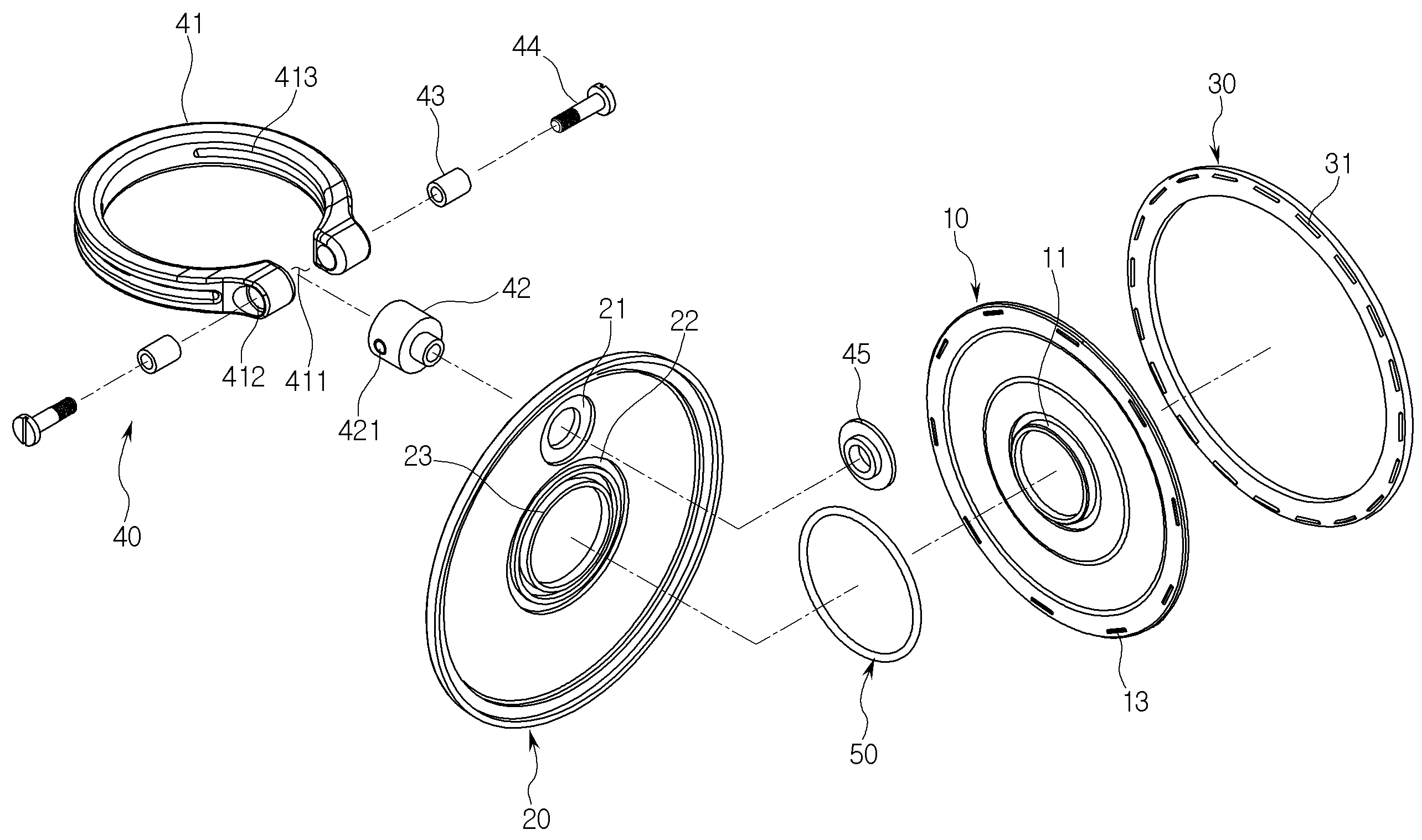
도 3은 도 2에 도시된 휴대용 전자기기의 지지장치의 분해 사시도,
도 4는 도 2에 도시된 고정 부재, 회전 부재, 회전 지지 부재의 결합 관계를 나타내는 단면도,
도 5는 본 발명에 따른 휴대용 전자기기의 지지장치의 사용 상태의 일 예를 나타내는 사시도,
도 6은 본 발명에 따른 휴대용 전자기기의 지지장치의 사용 상태의 다른 예를 나타내는 사시도,
도 7은 본 발명에 따른 휴대용 전자기기의 지지장치의 다른 예를 나타내는 사시도,
도 8은 본 발명에 따른 휴대용 전자기기의 지지장치의 또 다른 예를 나타내는 사시도,
도 9는 본 발명에 따른 휴대용 전자기기의 지지장치의 또 다른 예를 나타내는 사시도,
도 10은 본 발명에 따른 휴대용 전자기기의 지지장치의 또 다른 예를 나타내는 사시도.1 is a perspective view of a gripping mechanism of a conventional portable electronic device,
2 is a perspective view of a supporting device of a portable electronic device according to an embodiment of the present invention,
Fig. 3 is an exploded perspective view of the supporting device of the portable electronic device shown in Fig. 2,
4 is a cross-sectional view showing a coupling relationship between the fixing member, the rotary member, and the rotation support member shown in Fig. 2,
Fig. 5 is a perspective view showing an example of a use state of a supporting device of a portable electronic device according to the present invention, Fig.
6 is a perspective view showing another example of the use state of the support device of the portable electronic device according to the present invention,
7 is a perspective view showing another example of a supporting device for a portable electronic device according to the present invention,
8 is a perspective view showing still another example of a supporting device for a portable electronic device according to the present invention,
9 is a perspective view showing still another example of a supporting device for a portable electronic device according to the present invention,
10 is a perspective view showing still another example of a supporting device for a portable electronic device according to the present invention.
본 발명의 상기 및 그 밖의 목적과 새로운 특징은 본 명세서의 기술 및 첨부 도면에 의해 더욱 명확하게 될 것이다.These and other objects and novel features of the present invention will become more apparent from the description of the present specification and the accompanying drawings.
이하, 본 발명의 구성을 도면에 따라서 설명한다.Hereinafter, the configuration of the present invention will be described with reference to the drawings.
도 2는 본 발명의 일 실시 예에 따른 휴대용 전자기기의 지지장치의 사시도 이고, 도 3은 도 2에 도시된 휴대용 전자기기의 지지장치의 분해 사시도 이며, 도 4는 도 2에 도시된 고정 부재, 회전 부재, 회전 지지 부재의 결합 관계를 나타내는 단면도 이다.FIG. 2 is a perspective view of a supporting device for a portable electronic device according to an embodiment of the present invention, FIG. 3 is an exploded perspective view of the supporting device of the portable electronic device shown in FIG. 2, , The rotary member, and the rotary support member.
도 2 및 도 3에 도시된 바와 같이, 본 발명에 따른 휴대용 전자기기의 지지장치는 하부에 휴대용 전자기기의 배면에 분리 가능하게 부착되는 접착 패드를 구비한 고정 부재(10), 상기 고정 부재(10)에 회전 가능하게 끼워 맞추어지는 회전 부재(20), 상기 회전 부재(20)에 장착되는 회전 지지 부재(30), 상기 회전 부재(20)의 가장자리 부분에 장착되고 좌우 또는 상하로 이동 가능한 고리 부재(40) 및 상기 고리 부재(40)의 자중에 의해 상기 회전 부재가 회전하는 것을 방지하도록 상기 고정 부재(10)와 상기 회전 부재(20) 사이에 장착되는 오링(O-ring)을 포함하다.2 and 3, a supporting device for a portable electronic device according to the present invention includes a
상기 고정 부재(10)는 플라스틱과 같은 열가소성 수지로 이루어지고, 사출 성형 등에 의해 일체로 형성되며, 도 3 및 도 4에 도시된 된 바와 같이, 회전 부재(20)의 회전 중심을 유지하기 위해 상부 중앙 부분에 마련된 원형 돌출부(11), 회전 부재(20)와 회전 지지 부재(30)의 사이에 삽입되는 삽입부(12), 회전 부재(20)의 회전을 일정 간격으로 유지하기 위해 삽입부(12)의 상부 및 하부에 각각 마련된 다수의 돌기(13), 고리 부재(40)의 회전을 수용하는 원형의 오목부(14), 오링(50)과의 마찰력을 증대하기 위한 마찰부(15)를 구비한다.The
즉, 상기 고정 부재(10)는 대략 원형으로 형성되고, 상기 삽입부(12)는 'ㄱ'자 형상의 단차부를 갖게 형성되고, 회전 부재(20)와 회전 지지 부재(30)의 결합에 의해 단면이 U자 형상을 형성된 원형 홈에 삽입되어 회전 부재(20)와 회전 지지 부재(30)의 회전을 지지하는 기능을 갖는다.That is, the
상기 돌기(13)는 삽입부(13)의 상하에 각각 마련되어, 회전 부재(20)의 내면과 회전 지지 부재(30) 상면에서 회전 부재(20)의 내면과 회전 지지 부재(30)의 상면에서 회전력에 브레이크를 부여한다. 이와 같은 돌기(13)를 마련하는 것에 의해 고리 부재(40)의 자중에 의한 회전을 방지할 수 있다, 즉 본 발명에 따른 지지 장치는 사용자가 고리 부재(40)에 회전력을 부여할 때만 회전 부재(20)와 회전 지지 부재(30)가 삽입부(12) 사이에서 회전 가능하게 유지된다.The
또 다수의 돌기(13)의 각각은 회전 부재(20)와 회전 지지 부재(30)가 일 방향으로만(도 2에서 화살표 B 방향) 회전하도록 톱날 형상 또는 지그재그 형상으로 이루어질 수 있다. 이와 같이, 회전 부재(20)와 회전 지지 부재(30)가 일 방향으로만 회전하는 것에 의해 불필요한 회전을 방지할 수 있고, 휴대용 전자기기를 책상 등에서 지지 기구로 사용하는 경우, 휴대용 전자기기의 무게에 의한 고리 부재(40)의 회전을 방지할 수 있다. Each of the plurality of
상기 오목부(14)는 고리 부재(40)가 360도 회전을 실행할 수 있도록 고리 부재(40)의 이동 경로에 대응하여 원형으로 이루어지고, 마찰부(15)는 상기 오목부(14)에서 돌출하여 오링(50)과의 마찰력을 유지한다. 즉 본 발명에서는 삽입부(12)의 상부 및 하부에 마련된 돌기(13)와 오링(50)에 대한 마찰력을 부여하는 마찰부(15)를 마련하는 것에 의해 사용자가 회전력을 부여하는 경우에만 회전 부재(20)가 회전하게 된다. The
또 고정 부재(10)의 하부에는 대략 원형의 오목 부분이 형성되고, 오목 부분에는 휴대용 전자기기에 본 발명의 지지장치를 부착하기 위한 접착 패드(60)가 마련된다. 이와 같은 접착 패드(60)는 예를 들어 양면테이프의 기능을 구비한 것이 바람직하다. A substantially circular concave portion is formed in the lower portion of the fixing
상기 회전 부재(20)는 도 3 및 도 4에 도시된 바와 같이, 원반형상으로 이루어지고, 고정 부재(10)와 동일한 재질, 예를 들어 플라스틱과 같은 열가소성 수지로 이루어지고, 사출 성형 등에 의해 일체로 형성된다. 이 회전 부재(20)는 가장자리 부분에 마련되어 고리 부재(40)가 삽입 유지되는 관통구(21), 오링(50)을 삽입하기 위해 원형으로 이루어진 제1 삽입부(22), 고정 부재(10)와의 결합을 위해 원형 돌출부(11)과 억지 끼워 맞춤되는 원형 돌기부(23)를 구비한다.3 and 4, the
상기 관통구(21)는 도 3 및 도 4에 도시된 바와 같이, 종래의 구조와 달리 회전 부재(20)의 중심에서 벗어나 외곽 부분인 가장자리부(24)의 주변에 마련되고, 이 관통구(21)에 고리 부재(40)가 고정되고, 사용자가 고리 부재(40)를 회전시키는 것에 의해 회전 부재(20)가 고정 부재(10)의 원형 돌출부(11)를 기준으로 회전할 수 있다.As shown in FIGS. 3 and 4, the through-
상기 제1 삽입부(22)의 내경은 오링(50)의 외경보다 약간 작게 마련하여 탄성을 갖는 오링(50)을 제1 삽입부(22)에 억지 끼우는 것에 의해 오링(50)을 회전 부재(20)의 하부에 고정할 수 있다.The inner diameter of the
상기 원형 돌기부(23)의 내경은 원형 돌출부(11)의 외경과 거의 동일하게 마련하여 원형 돌기부(23)를 원형 돌출부(11)에 억지 끼우는 것에 의해 회전 부재(20)와 고정 부재(10)가 회전 가능하게 장착된다. 또 회전 부재(20)와 고정 부재(10)의 결합력 강화하기 위해 회전 부재(20)와 고정 부재(10)의 측면에 각각 돌기와 홈을 만들어 결합하는 구조를 적용할 수도 있다.The inner diameter of the
상기 회전 지지 부재(30)는 도 3에 도시된 바와 같이, 고정 부재(10)의 삽입부(12) 하부에 장착되도록 중공형으로 마련되고, 상부에 다수의 접착용 돌기(31)가 마련된다. 이 접착용 돌기(31)는 회전 부재(20)의 가장자리부(24)의 하부에서 열 또는 초음파 용접 등의 방법에 의해 회전 부재(20)와 회전 지지 부재(30)의 결합이 이루어지고, 회전 부재(20)와 회전 지지 부재(30)를 단면이 도 3에 도시된 바와 같이, U자 형상으로 형성하고, 상기 삽입부(12)가 이 U자 형상의 원형 홈에 삽입된다. 따라서, 본 발명에 따른 지지장치는 삽입부(12)를 기준으로 하여 회전 부재(20)와 회전 지지 부재(30)가 일체화되어 360도 회전 가능하게 된다. 3, the
상기 고리 부재(40)는 도 2에서 좌우 방향(화살표 A)으로 회전 가능하고 대략 내경이 원형으로 이루어진 고리(41), 회전축(42), 탄성부(43), 체결부로 이루어지고, 상기 고리(41)는 도 3에 도시된 바와 같이, 일부분이 개방된 개방부(411)와 상기 개방부(411)의 양단 내부에 형성된 축 홀(412)을 구비하고, 측면에는 지지장치의 사용 시 필요한 연결 부재 등을 결합하기 위한 삽입구(413)이 마련된다. The
상기 회전축(43)은 축 홀(412)에 대응하여 결합 홀(421)이 마련되고 상부가 개방부(411)에 삽입되고, 하부는 회전 부재(20)에 마련된 관통구(21)에 삽입되어 리벳(45)에 의해 고정된다. The
상기 고리(41)와 회전체(42)는 견고성을 유지하기 위해 금속재로 이루어지는 것이 바람직하지만 이에 한정되는 것은 아니고, 고강도 플라스틱으로 이루어질 수 있다. 또 회전축(42)이 리벳(45)에 의해 회전 부재(20)에 고정되는 구조로 설명하였지만, 이에 한정되는 것은 아니고, 회전축(42)의 하부에 돌출편을 마련하고, 이 돌출편을 관통구(21)에 압착으로 고정할 수도 있다. It is preferable that the
상기 탄성부(43)는 중공 형상으로 마련되어 축 홀(412) 내에 삽입되며, 탄성을 가지며 일정한 마찰력을 갖는 물질로서 예를 들어, 폴리아세탈, MC 나일론, 폴리우레탄, 폴리이소프렌, 폴리뷰타디엔고무, 폴리아크릴레이트고무, 폴리에테르고무 등과 같은 내마모성이 우수한 엔지니어링 플라스틱을 사용할 수 있다, 이 탄성부(43)는 고리(41)와 체결부 사이에 일정한 압력 및 마찰력을 제공하며, 이 탄성부(43)의 마찰력으로 인해 고리(41)가 자중에 의해 회전하는 것을 방지할 수 있다.The
상기 체결부는 도 3에 도시된 바와 같이, 한 쌍의 볼트(44)로 이루어지고, 상기 볼트(44)는 탄성부(43), 축 홀(412)을 거쳐 결합 홀(421)에 나사 결합되는 것에 의해 고리(41)가 자중에 의해 회전하는 것을 더욱 방지할 수 있다. 3, the fastening portion is formed of a pair of
즉 종래의 기술에서 탄성부에 의해서만 고리의 자중에 의한 회전을 방지하였지만, 고리 부재의 빈번한 사용에 의해 결합관계가 느슨해져 지지 기능을 충분히 달성할 수 없다는 문제가 발생하였다. 본 발명에 따른 지지장치는 이를 해결하기 위해 사용자가 볼트(44)의 조임 상태를 조작하는 것에 의해 탄성부(43)의 기능 저하에도 불구하고, 고리(41)의 자중에 의한 회전을 방지할 수 있다.That is, in the conventional technique, rotation of the ring due to its own weight is prevented only by the elastic portion, but the frequent use of the ring member loosens the coupling relation, and the support function can not be sufficiently achieved. The support device according to the present invention can prevent the rotation of the
상술한 바와 같이, 본 발명에 따른 휴대용 전자기기의 지지장치에서는 회전 부재(20)의 관통구(21)에 회전축(42)을 고정하고, 제1 삽입부(22)에 오링(50)을 끼워 맞추고, 원형 돌기부(23)와 고정 부재(10)의 원형 돌출부(11)를 끼워 맞춘 후, 회전 지지 부재(30)를 가장자리부(24)에 결합하며, 계속해서 회전축(24)에 고리(41)를 체결하는 것에 의해 도 2에 도시된 바와 같은 구조의 지지장치가 완성된다.The
다음에, 도 5 및 도 6에 따라 본 발명에 따른 지지장치의 사용 상태를 설명한다.Next, the use state of the supporting apparatus according to the present invention will be described with reference to Figs. 5 and 6. Fig.
도 5는 본 발명에 따른 휴대용 전자기기의 지지장치의 사용 상태의 일 예를 나타내는 사시도 이고, 도 6은 본 발명에 따른 휴대용 전자기기의 지지장치의 사용 상태의 다른 예를 나타내는 사시도 이다.FIG. 5 is a perspective view showing an example of a use state of a support apparatus of a portable electronic apparatus according to the present invention, and FIG. 6 is a perspective view showing another example of a use state of a support apparatus of a portable electronic apparatus according to the present invention.
도 5에서 알 수 있는 바와 같이, 본 발명에 따른 지지장치는 종래의 기술과 달리 고정 부재의 중앙 부분이 아니라, 가장자리 부분에 고리 부재가 마련되므로 휴대용 전자기기를 보다 안정적으로 지지할 수 있다. 또 고리 부재가 회전 부재의 가장자리 부분에 장착되어 무게 중심이 주변에 형성되므로, 전자기기에서 접착 패드를 분리하는 경우 지지장치를 용이하게 분리할 수 있다.As can be seen from FIG. 5, the supporting device according to the present invention is capable of supporting the portable electronic device more stably because the supporting member according to the present invention is provided with a ring member at the edge portion instead of the center portion of the fixing member. In addition, since the loop member is attached to the edge portion of the rotating member and the center of gravity is formed around the rotating member, the supporting device can be easily separated when the adhesive pad is detached from the electronic device.
도 6은 도 5의 상태에서 고리 부재를 회전 부재에 의해 180도 회전시켜 사용한 상태로, 단순히 회전 부재를 회전시키는 것에 의해 종래 기술에 비해 거치 각도를 확대할 수 있다.Fig. 6 can enlarge the mounting angle as compared with the related art by simply rotating the rotary member in a state in which the ring member is rotated 180 degrees by the rotary member in the state of Fig.
다음에 본 발명에 따른 변형 예를 도 7 내지 도 10에 따라 설명한다.Next, a modification according to the present invention will be described with reference to Figs. 7 to 10. Fig.
또 이 변형 예에서는 도 2 내지 도 4에 도시된 구조와 동일 구조에 대해서는 동일 부호를 병기하고, 그 반복적인 설명은 생략합니다.In this modified example, the same reference numerals are assigned to the same structures as those shown in Figs. 2 to 4, and repetitive description thereof will be omitted.
도 7은 본 발명에 따른 휴대용 전자기기의 지지장치의 다른 예를 나타내는 사시도 이고, 도 8은 본 발명에 따른 휴대용 전자기기의 지지장치의 또 다른 예를 나타내는 사시도 이고, 도 9는 본 발명에 따른 휴대용 전자기기의 지지장치의 또 다른 예를 나타내는 사시도 이며, 도 10은 본 발명에 따른 휴대용 전자기기의 지지장치의 또 다른 예를 나타내는 사시도 이다.FIG. 7 is a perspective view showing another example of a supporting device for a portable electronic device according to the present invention, FIG. 8 is a perspective view showing still another example of a supporting device for a portable electronic device according to the present invention, Fig. 10 is a perspective view showing still another example of a supporting device for a portable electronic device according to the present invention. Fig. 10 is a perspective view showing another example of a supporting device for a portable electronic device.
도 3의 구조에서는 회전 부재(10)의 하부에 회전 지지 부재(30)가 결합된 구조로 설명하였지만, 도 7에 도시된 바와 같이 회전 지지부(60)를 마련하고, 회전 부재(20)가 이 회전 지지부(60) 내에 마련된 구조를 채용할 수 있다. 도 7과 같이 회전 지지부(60) 내에 회전 부재를 마련하는 경우, 지지장치의 조립을 단순화할 수 있다. 그러나 도 2에 도시된 구조에 비해 회전 각도가 작으므로, 거치 각도도 작게된다.3, the
또 도 2의 구조에서는 고리 부재(40)의 고리의 외형이 대략 원형인 구조로 설명하였지만, 도 8에 도시된 바와 같이 내부는 원형으로 형성하고 외부는 사각형상으로 마련될 수도 있다. 또 도 9와 같이, 고리 부재의 고리의 일단부를 편평한 상태로 마련할 수 있다. 도 8 및 도 9에 도시된 구조를 적용하는 경우, 책상 등과 같이 평탄한 바닥에서 지지장치를 견고하게 지지할 수 있지만, 평탄하지 않은 장도, 예를 들어 바위 등과 같이 굴곡이 있는 바닥에서는 지지하는 것이 곤란하게 될 수도 있다.In the structure of FIG. 2, the outer shape of the ring of the
또 본 발명에 따른 지지장치에서는 도 10에 도시된 바와 같이, 회전 부재의 외부에 광고 부재(70)를 마련하여 사용할 수 있다. 이와 같이 지지장치에 광고 부재(70)를 마련하는 경우, 사용자가 항상 휴대용 전자기기를 소지하고 다니므로, 광고 효과를 극대화할 수 있다. 또, 이러한 광고 부재(70)는 별도로 마련한 스티커 등의 소재를 회전 부재의 외부에 부착하거나, 회전 부재의 제조 시 일체화하여 제작할 수도 있다.In addition, in the supporting apparatus according to the present invention, as shown in FIG. 10, the
이상 본 발명자에 의해서 이루어진 발명을 상기 실시 예에 따라 구체적으로 설명하였지만, 본 발명은 상기 실시 예에 한정되는 것은 아니고 그 요지를 이탈하지 않는 범위에서 여러 가지로 변경 가능한 것은 물론이다.Although the present invention has been described in detail with reference to the above embodiments, it is needless to say that the present invention is not limited to the above-described embodiments, and various modifications may be made without departing from the spirit of the present invention.
본 발명에 따른 휴대용 전자기기의 지지장치를 사용하는 것에 의해 전자기기의 지지 각도를 최대로 할 수 있다.The supporting angle of the electronic device can be maximized by using the supporting device of the portable electronic device according to the present invention.
10 : 고정 부재
20 : 회전 부재
30 : 회전 지지 부재
40 : 고리 부재10: Fixing member
20: Rotating member
30:
40:
Claims (9)
상기 고정 부재(10)에는 상기 회전 부재(20)와 회전 지지 부재(30)의 사이에 삽입되는 삽입부(12)와 상기 회전 부재(20)의 회전을 일정 간격으로 유지하기 위해 상기 삽입부의 상부 및 하부에 각각 마련된 다수의 돌기(13)가 마련되고,
상기 다수의 돌기(13)의 각각은 상기 회전 부재(20)와 회전 지지 부재(30)가 일 방향으로만 회전하도록 톱날 형상 또는 지그재그 형상으로 이루어지고,
상기 회전 부재(20)에는 상부 가장자리 부분에 마련되어 상기 고리 부재(40)가 삽입 유지되는 관통구(21)가 마련되고,
상기 고정 부재(10)에는 상기 고리 부재(40)의 회전을 수용하는 원형의 오목부(14)가 마련되고,
상기 삽입부(12)를 기준으로 하여 상기 회전 부재(20)와 회전 지지 부재(30)가 열 또는 초음파 용접에 의해 일체화되어 360도 회전 가능한 것을 특징으로 하는 휴대용 전자기기의 지지장치.(10) having an adhesive pad detachably attached to a back surface of a portable electronic device at a lower portion thereof, a rotary member (20) rotatably fitted to the fixing member, a rotary support member 30), a ring member (40) mounted on an edge portion of the rotary member (20) and movable leftward or rightward or upward and downward,
The fixing member 10 is provided with an insertion portion 12 inserted between the rotary member 20 and the rotary support member 30 and an upper portion of the insertion portion 12 to maintain the rotation of the rotary member 20 at a constant interval. And a plurality of projections 13 provided at the lower portion thereof,
Each of the plurality of projections 13 is formed in a sawtooth shape or a zigzag shape so that the rotary member 20 and the rotary support member 30 rotate only in one direction,
The rotary member 20 is provided with a through-hole 21 provided at an upper edge portion thereof and into which the ring member 40 is inserted,
The fixing member 10 is provided with a circular concave portion 14 for receiving the rotation of the ring member 40,
Wherein the rotary member (20) and the rotary support member (30) are integrated by thermal or ultrasonic welding and are rotatable 360 degrees with respect to the insertion portion (12).
상기 고리 부재의 자중에 의해 상기 회전 부재가 회전하는 것을 방지하도록 상기 고정 부재(10)와 상기 회전 부재(20) 사이에 장착되는 오링(O-ring,50)을 더 포함하고,
상기 회전 부재는 원반형상으로 이루어진 것을 특징으로 하는 휴대용 전자기기의 지지장치.The method of claim 1,
Further comprising an O-ring (50) mounted between the fixing member (10) and the rotary member (20) to prevent the rotary member from rotating due to the self weight of the ring member,
Wherein the rotating member is formed in a disk shape.
상기 고정 부재(10)에는 상기 회전 부재의 회전 중심을 유지하기 위해 상부 중앙 부분에 마련된 원형 돌출부(11), 상기 오링과의 마찰력을 증대하기 위한 마찰부(15)가 더 마련된 것을 특징으로 하는 휴대용 전자기기의 지지장치.3. The method of claim 2,
Wherein the fixing member is further provided with a circular protruding portion provided at an upper center portion and a friction portion for increasing frictional force with the O-ring in order to maintain the center of rotation of the rotary member. Support device for electronic devices.
상기 회전 부재(20)와 회전 지지 부재(30)의 결합에 의해 단면이 U자 형상을 형성하고, 상기 삽입부(12)는 U자 형상의 원형 홈에 삽입되는 것을 특징으로 하는 휴대용 전자기기의 지지장치.4. The method of claim 3,
Wherein a U-shaped cross section is formed by engagement of the rotary member (20) and the rotary support member (30), and the insertion portion (12) is inserted into a U-shaped circular groove Supporting device.
상기 회전 부재의 내부에는 상기 오링을 삽입하기 위해 원형으로 이루어진 제1 삽입부, 상기 원형 돌출부와 끼워 맞추어지는 원형 돌기부가 형성된 것을 특징으로 하는 휴대용 전자기기의 지지장치.5. The method of claim 4,
Wherein the rotary member has a first insertion portion formed in a circular shape for insertion of the O-ring, and a circular protrusion portion fitted to the circular protrusion portion.
상기 고리 부재는 원형으로 이루어지고, 일부분이 개방된 개방부와 상기 개방부의 양단 내부에 형성된 축 홀을 구비한 고리, 상기 축 홀에 대응하여 결합 홀이 마련되고 상기 개방부에 삽입되는 회전축, 상기 축 홀에 삽입되는 탄성부, 상기 탄성부를 거쳐 상기 결합 홀에 체결되는 체결부를 구비한 것을 특징으로 하는 휴대용 전자기기의 지지장치.The method of claim 6,
Wherein the ring member has a circular shape and includes a ring having an opening portion with a part opened and a shaft hole formed inside both ends of the opening portion, a rotation shaft provided with a coupling hole corresponding to the shaft hole and inserted into the opening portion, An elastic portion inserted into the shaft hole, and a fastening portion fastened to the fastening hole through the elastic portion.
상기 회전축은 상기 관통구를 거쳐 상기 회전 부재의 외부에 고정되고,
상기 체결부는 한 쌍의 볼트로 이루어지고, 상기 볼트에 의해 상기 결합 홀에 나사 결합되는 것을 특징으로 하는 휴대용 전자기기의 지지장치.8. The method of claim 7,
The rotating shaft is fixed to the outside of the rotating member via the through-hole,
Wherein the fastening portion comprises a pair of bolts and is screwed to the coupling hole by the bolts.
상기 회전 부재의 외부에는 광고 부재가 마련된 것을 특징으로 하는 휴대용 전자기기의 지지장치.
The method of claim 1,
And the advertising member is provided on the outside of the rotating member.
Priority Applications (1)
| Application Number | Priority Date | Filing Date | Title |
|---|---|---|---|
| KR1020160079410A KR101856445B1 (en) | 2016-06-24 | 2016-06-24 | Supporting device of portable electronic apparatus |
Applications Claiming Priority (1)
| Application Number | Priority Date | Filing Date | Title |
|---|---|---|---|
| KR1020160079410A KR101856445B1 (en) | 2016-06-24 | 2016-06-24 | Supporting device of portable electronic apparatus |
Publications (2)
| Publication Number | Publication Date |
|---|---|
| KR20180000979A KR20180000979A (en) | 2018-01-04 |
| KR101856445B1 true KR101856445B1 (en) | 2018-05-10 |
Family
ID=60998103
Family Applications (1)
| Application Number | Title | Priority Date | Filing Date |
|---|---|---|---|
| KR1020160079410A Expired - Fee Related KR101856445B1 (en) | 2016-06-24 | 2016-06-24 | Supporting device of portable electronic apparatus |
Country Status (1)
| Country | Link |
|---|---|
| KR (1) | KR101856445B1 (en) |
Citations (2)
| Publication number | Priority date | Publication date | Assignee | Title |
|---|---|---|---|---|
| KR101062570B1 (en) * | 2011-01-21 | 2011-09-05 | 김혜련 | Finger ring for mobile terminal |
| KR101624056B1 (en) * | 2014-12-31 | 2016-05-24 | 전영병 | A supporter for a terminal |
-
2016
- 2016-06-24 KR KR1020160079410A patent/KR101856445B1/en not_active Expired - Fee Related
Patent Citations (2)
| Publication number | Priority date | Publication date | Assignee | Title |
|---|---|---|---|---|
| KR101062570B1 (en) * | 2011-01-21 | 2011-09-05 | 김혜련 | Finger ring for mobile terminal |
| KR101624056B1 (en) * | 2014-12-31 | 2016-05-24 | 전영병 | A supporter for a terminal |
Also Published As
| Publication number | Publication date |
|---|---|
| KR20180000979A (en) | 2018-01-04 |
Similar Documents
| Publication | Publication Date | Title |
|---|---|---|
| KR200483203Y1 (en) | Accessory for a mobile device | |
| US9954569B2 (en) | Elastic securing apparatus and mounting system for electronic device | |
| KR101062570B1 (en) | Finger ring for mobile terminal | |
| CN110025123B (en) | Grasping devices for handheld devices | |
| KR101062557B1 (en) | Mobile terminal mounting ring and mobile terminal case having the same | |
| KR101481256B1 (en) | Accessary for a portable device | |
| US11292543B2 (en) | Systems and methods for a mountable multi-positional device holder | |
| US8333353B1 (en) | Compact, portable, temporary mount for portable devices | |
| US9445512B2 (en) | Holder having adjustable clamping orientation | |
| KR200476134Y1 (en) | Apparatus for mounting a mobile device on a vehicle | |
| US9451817B2 (en) | Accessory mount with friction hinge plate | |
| JP2014503160A (en) | Finger ring for portable terminal and portable terminal case provided with the same | |
| US20160039357A1 (en) | Mobile device accessory and apparatus for mounting the same on an automotive | |
| KR101629434B1 (en) | Magic strap | |
| JP2015514365A (en) | Multifunctional accessories for portable devices | |
| KR101733435B1 (en) | Ring holder of portable device | |
| KR101856447B1 (en) | Supporting device of portable electronic apparatus | |
| WO2017120231A1 (en) | Elastic securing apparatus and mounting system for electronic device | |
| KR20180000979A (en) | Supporting device of portable electronic apparatus | |
| KR20180060460A (en) | self camera stick with attaching bicycle | |
| KR101738616B1 (en) | Apparatus for mounting mobile phone | |
| KR20170111404A (en) | A smartphone cradle | |
| KR20160003392A (en) | Holder for mobile terminal and mobile terminal case thereof | |
| KR101485138B1 (en) | Adhesive type goods cradle | |
| KR101692961B1 (en) | Holder for portable apparatus |
Legal Events
| Date | Code | Title | Description |
|---|---|---|---|
| A201 | Request for examination | ||
| PA0109 | Patent application |
St.27 status event code: A-0-1-A10-A12-nap-PA0109 |
|
| PA0201 | Request for examination |
St.27 status event code: A-1-2-D10-D11-exm-PA0201 |
|
| D13-X000 | Search requested |
St.27 status event code: A-1-2-D10-D13-srh-X000 |
|
| D14-X000 | Search report completed |
St.27 status event code: A-1-2-D10-D14-srh-X000 |
|
| E902 | Notification of reason for refusal | ||
| PE0902 | Notice of grounds for rejection |
St.27 status event code: A-1-2-D10-D21-exm-PE0902 |
|
| R17-X000 | Change to representative recorded |
St.27 status event code: A-3-3-R10-R17-oth-X000 |
|
| E13-X000 | Pre-grant limitation requested |
St.27 status event code: A-2-3-E10-E13-lim-X000 |
|
| P11-X000 | Amendment of application requested |
St.27 status event code: A-2-2-P10-P11-nap-X000 |
|
| P13-X000 | Application amended |
St.27 status event code: A-2-2-P10-P13-nap-X000 |
|
| E902 | Notification of reason for refusal | ||
| PE0902 | Notice of grounds for rejection |
St.27 status event code: A-1-2-D10-D21-exm-PE0902 |
|
| P11-X000 | Amendment of application requested |
St.27 status event code: A-2-2-P10-P11-nap-X000 |
|
| P13-X000 | Application amended |
St.27 status event code: A-2-2-P10-P13-nap-X000 |
|
| PG1501 | Laying open of application |
St.27 status event code: A-1-1-Q10-Q12-nap-PG1501 |
|
| E701 | Decision to grant or registration of patent right | ||
| PE0701 | Decision of registration |
St.27 status event code: A-1-2-D10-D22-exm-PE0701 |
|
| GRNT | Written decision to grant | ||
| PR0701 | Registration of establishment |
St.27 status event code: A-2-4-F10-F11-exm-PR0701 |
|
| PR1002 | Payment of registration fee |
St.27 status event code: A-2-2-U10-U11-oth-PR1002 Fee payment year number: 1 |
|
| PG1601 | Publication of registration |
St.27 status event code: A-4-4-Q10-Q13-nap-PG1601 |
|
| PR1001 | Payment of annual fee |
St.27 status event code: A-4-4-U10-U11-oth-PR1001 Fee payment year number: 4 |
|
| PR1001 | Payment of annual fee |
St.27 status event code: A-4-4-U10-U11-oth-PR1001 Fee payment year number: 5 |
|
| PR1001 | Payment of annual fee |
St.27 status event code: A-4-4-U10-U11-oth-PR1001 Fee payment year number: 6 |
|
| PC1903 | Unpaid annual fee |
St.27 status event code: A-4-4-U10-U13-oth-PC1903 Not in force date: 20240504 Payment event data comment text: Termination Category : DEFAULT_OF_REGISTRATION_FEE |
|
| PC1903 | Unpaid annual fee |
St.27 status event code: N-4-6-H10-H13-oth-PC1903 Ip right cessation event data comment text: Termination Category : DEFAULT_OF_REGISTRATION_FEE Not in force date: 20240504 |