KR101752434B1 - Broadcast transmission apparatus, operation method of broadcast transmission apparatus, broadcast reception apparatus, and operation method of broadcast reception apparatus - Google Patents
Broadcast transmission apparatus, operation method of broadcast transmission apparatus, broadcast reception apparatus, and operation method of broadcast reception apparatus Download PDFInfo
- Publication number
- KR101752434B1 KR101752434B1 KR1020167001563A KR20167001563A KR101752434B1 KR 101752434 B1 KR101752434 B1 KR 101752434B1 KR 1020167001563 A KR1020167001563 A KR 1020167001563A KR 20167001563 A KR20167001563 A KR 20167001563A KR 101752434 B1 KR101752434 B1 KR 101752434B1
- Authority
- KR
- South Korea
- Prior art keywords
- service
- broadcast
- information
- field
- data
- Prior art date
Links
- 238000000034 method Methods 0.000 title claims abstract description 126
- 230000005540 biological transmission Effects 0.000 title description 214
- 230000011664 signaling Effects 0.000 claims description 204
- 230000008569 process Effects 0.000 claims description 67
- NGVDGCNFYWLIFO-UHFFFAOYSA-N pyridoxal 5'-phosphate Chemical compound CC1=NC=C(COP(O)(O)=O)C(C=O)=C1O NGVDGCNFYWLIFO-UHFFFAOYSA-N 0.000 claims description 30
- 238000012545 processing Methods 0.000 claims description 23
- 230000008054 signal transmission Effects 0.000 abstract description 8
- 108091006146 Channels Proteins 0.000 description 78
- 101000596046 Homo sapiens Plastin-2 Proteins 0.000 description 77
- 102100035182 Plastin-2 Human genes 0.000 description 77
- 238000010586 diagram Methods 0.000 description 48
- 238000013507 mapping Methods 0.000 description 41
- 101000596041 Homo sapiens Plastin-1 Proteins 0.000 description 27
- 102100035181 Plastin-1 Human genes 0.000 description 27
- 238000003780 insertion Methods 0.000 description 24
- 230000037431 insertion Effects 0.000 description 24
- 230000003068 static effect Effects 0.000 description 20
- 230000008859 change Effects 0.000 description 17
- 230000006978 adaptation Effects 0.000 description 14
- 238000004891 communication Methods 0.000 description 13
- 239000000284 extract Substances 0.000 description 13
- 230000006870 function Effects 0.000 description 12
- 239000000969 carrier Substances 0.000 description 9
- 230000006835 compression Effects 0.000 description 9
- 238000007906 compression Methods 0.000 description 9
- 239000004065 semiconductor Substances 0.000 description 9
- 239000011159 matrix material Substances 0.000 description 8
- 230000009467 reduction Effects 0.000 description 8
- 230000001174 ascending effect Effects 0.000 description 7
- 239000000872 buffer Substances 0.000 description 6
- 238000001514 detection method Methods 0.000 description 6
- 238000012986 modification Methods 0.000 description 5
- 230000004048 modification Effects 0.000 description 5
- 230000002441 reversible effect Effects 0.000 description 5
- 101150071746 Pbsn gene Proteins 0.000 description 4
- 238000012937 correction Methods 0.000 description 4
- 230000000694 effects Effects 0.000 description 4
- 238000005562 fading Methods 0.000 description 4
- 238000007726 management method Methods 0.000 description 4
- 239000012092 media component Substances 0.000 description 4
- 238000012360 testing method Methods 0.000 description 4
- 230000001419 dependent effect Effects 0.000 description 3
- 230000007246 mechanism Effects 0.000 description 3
- 238000001824 photoionisation detection Methods 0.000 description 3
- 238000004904 shortening Methods 0.000 description 3
- 230000001360 synchronised effect Effects 0.000 description 3
- 230000002123 temporal effect Effects 0.000 description 3
- 238000012217 deletion Methods 0.000 description 2
- 230000037430 deletion Effects 0.000 description 2
- 238000013461 design Methods 0.000 description 2
- 230000009471 action Effects 0.000 description 1
- 230000004913 activation Effects 0.000 description 1
- 238000013459 approach Methods 0.000 description 1
- 238000005388 cross polarization Methods 0.000 description 1
- 125000004122 cyclic group Chemical group 0.000 description 1
- 230000001934 delay Effects 0.000 description 1
- 230000003111 delayed effect Effects 0.000 description 1
- 239000006185 dispersion Substances 0.000 description 1
- 238000005538 encapsulation Methods 0.000 description 1
- 238000005516 engineering process Methods 0.000 description 1
- 238000013213 extrapolation Methods 0.000 description 1
- 230000007274 generation of a signal involved in cell-cell signaling Effects 0.000 description 1
- 230000021715 photosynthesis, light harvesting Effects 0.000 description 1
- 238000001228 spectrum Methods 0.000 description 1
- 238000012546 transfer Methods 0.000 description 1
Images


Classifications
-
- H—ELECTRICITY
- H04—ELECTRIC COMMUNICATION TECHNIQUE
- H04N—PICTORIAL COMMUNICATION, e.g. TELEVISION
- H04N21/00—Selective content distribution, e.g. interactive television or video on demand [VOD]
- H04N21/20—Servers specifically adapted for the distribution of content, e.g. VOD servers; Operations thereof
- H04N21/23—Processing of content or additional data; Elementary server operations; Server middleware
- H04N21/238—Interfacing the downstream path of the transmission network, e.g. adapting the transmission rate of a video stream to network bandwidth; Processing of multiplex streams
- H04N21/2383—Channel coding or modulation of digital bit-stream, e.g. QPSK modulation
-
- H—ELECTRICITY
- H04—ELECTRIC COMMUNICATION TECHNIQUE
- H04N—PICTORIAL COMMUNICATION, e.g. TELEVISION
- H04N21/00—Selective content distribution, e.g. interactive television or video on demand [VOD]
- H04N21/20—Servers specifically adapted for the distribution of content, e.g. VOD servers; Operations thereof
- H04N21/23—Processing of content or additional data; Elementary server operations; Server middleware
- H04N21/236—Assembling of a multiplex stream, e.g. transport stream, by combining a video stream with other content or additional data, e.g. inserting a URL [Uniform Resource Locator] into a video stream, multiplexing software data into a video stream; Remultiplexing of multiplex streams; Insertion of stuffing bits into the multiplex stream, e.g. to obtain a constant bit-rate; Assembling of a packetised elementary stream
-
- H—ELECTRICITY
- H04—ELECTRIC COMMUNICATION TECHNIQUE
- H04W—WIRELESS COMMUNICATION NETWORKS
- H04W76/00—Connection management
- H04W76/40—Connection management for selective distribution or broadcast
-
- H—ELECTRICITY
- H04—ELECTRIC COMMUNICATION TECHNIQUE
- H04H—BROADCAST COMMUNICATION
- H04H20/00—Arrangements for broadcast or for distribution combined with broadcast
- H04H20/26—Arrangements for switching distribution systems
-
- H—ELECTRICITY
- H04—ELECTRIC COMMUNICATION TECHNIQUE
- H04H—BROADCAST COMMUNICATION
- H04H60/00—Arrangements for broadcast applications with a direct linking to broadcast information or broadcast space-time; Broadcast-related systems
- H04H60/35—Arrangements for identifying or recognising characteristics with a direct linkage to broadcast information or to broadcast space-time, e.g. for identifying broadcast stations or for identifying users
- H04H60/48—Arrangements for identifying or recognising characteristics with a direct linkage to broadcast information or to broadcast space-time, e.g. for identifying broadcast stations or for identifying users for recognising items expressed in broadcast information
-
- H—ELECTRICITY
- H04—ELECTRIC COMMUNICATION TECHNIQUE
- H04H—BROADCAST COMMUNICATION
- H04H60/00—Arrangements for broadcast applications with a direct linking to broadcast information or broadcast space-time; Broadcast-related systems
- H04H60/68—Systems specially adapted for using specific information, e.g. geographical or meteorological information
- H04H60/73—Systems specially adapted for using specific information, e.g. geographical or meteorological information using meta-information
-
- H—ELECTRICITY
- H04—ELECTRIC COMMUNICATION TECHNIQUE
- H04L—TRANSMISSION OF DIGITAL INFORMATION, e.g. TELEGRAPHIC COMMUNICATION
- H04L1/00—Arrangements for detecting or preventing errors in the information received
-
- H—ELECTRICITY
- H04—ELECTRIC COMMUNICATION TECHNIQUE
- H04L—TRANSMISSION OF DIGITAL INFORMATION, e.g. TELEGRAPHIC COMMUNICATION
- H04L1/00—Arrangements for detecting or preventing errors in the information received
- H04L1/004—Arrangements for detecting or preventing errors in the information received by using forward error control
- H04L1/0041—Arrangements at the transmitter end
-
- H—ELECTRICITY
- H04—ELECTRIC COMMUNICATION TECHNIQUE
- H04L—TRANSMISSION OF DIGITAL INFORMATION, e.g. TELEGRAPHIC COMMUNICATION
- H04L1/00—Arrangements for detecting or preventing errors in the information received
- H04L1/004—Arrangements for detecting or preventing errors in the information received by using forward error control
- H04L1/0056—Systems characterized by the type of code used
- H04L1/0071—Use of interleaving
-
- H—ELECTRICITY
- H04—ELECTRIC COMMUNICATION TECHNIQUE
- H04L—TRANSMISSION OF DIGITAL INFORMATION, e.g. TELEGRAPHIC COMMUNICATION
- H04L1/00—Arrangements for detecting or preventing errors in the information received
- H04L1/004—Arrangements for detecting or preventing errors in the information received by using forward error control
- H04L1/0075—Transmission of coding parameters to receiver
-
- H—ELECTRICITY
- H04—ELECTRIC COMMUNICATION TECHNIQUE
- H04N—PICTORIAL COMMUNICATION, e.g. TELEVISION
- H04N21/00—Selective content distribution, e.g. interactive television or video on demand [VOD]
- H04N21/20—Servers specifically adapted for the distribution of content, e.g. VOD servers; Operations thereof
- H04N21/23—Processing of content or additional data; Elementary server operations; Server middleware
- H04N21/236—Assembling of a multiplex stream, e.g. transport stream, by combining a video stream with other content or additional data, e.g. inserting a URL [Uniform Resource Locator] into a video stream, multiplexing software data into a video stream; Remultiplexing of multiplex streams; Insertion of stuffing bits into the multiplex stream, e.g. to obtain a constant bit-rate; Assembling of a packetised elementary stream
- H04N21/2362—Generation or processing of Service Information [SI]
-
- H—ELECTRICITY
- H04—ELECTRIC COMMUNICATION TECHNIQUE
- H04N—PICTORIAL COMMUNICATION, e.g. TELEVISION
- H04N21/00—Selective content distribution, e.g. interactive television or video on demand [VOD]
- H04N21/40—Client devices specifically adapted for the reception of or interaction with content, e.g. set-top-box [STB]; Operations thereof
- H04N21/41—Structure of client; Structure of client peripherals
- H04N21/4104—Peripherals receiving signals from specially adapted client devices
- H04N21/4108—Peripherals receiving signals from specially adapted client devices characterised by an identification number or address, e.g. local network address
-
- H—ELECTRICITY
- H04—ELECTRIC COMMUNICATION TECHNIQUE
- H04N—PICTORIAL COMMUNICATION, e.g. TELEVISION
- H04N21/00—Selective content distribution, e.g. interactive television or video on demand [VOD]
- H04N21/40—Client devices specifically adapted for the reception of or interaction with content, e.g. set-top-box [STB]; Operations thereof
- H04N21/41—Structure of client; Structure of client peripherals
- H04N21/426—Internal components of the client ; Characteristics thereof
- H04N21/42684—Client identification by a unique number or address, e.g. serial number, MAC address, socket ID
-
- H—ELECTRICITY
- H04—ELECTRIC COMMUNICATION TECHNIQUE
- H04N—PICTORIAL COMMUNICATION, e.g. TELEVISION
- H04N21/00—Selective content distribution, e.g. interactive television or video on demand [VOD]
- H04N21/40—Client devices specifically adapted for the reception of or interaction with content, e.g. set-top-box [STB]; Operations thereof
- H04N21/43—Processing of content or additional data, e.g. demultiplexing additional data from a digital video stream; Elementary client operations, e.g. monitoring of home network or synchronising decoder's clock; Client middleware
- H04N21/434—Disassembling of a multiplex stream, e.g. demultiplexing audio and video streams, extraction of additional data from a video stream; Remultiplexing of multiplex streams; Extraction or processing of SI; Disassembling of packetised elementary stream
- H04N21/4345—Extraction or processing of SI, e.g. extracting service information from an MPEG stream
-
- H—ELECTRICITY
- H04—ELECTRIC COMMUNICATION TECHNIQUE
- H04N—PICTORIAL COMMUNICATION, e.g. TELEVISION
- H04N21/00—Selective content distribution, e.g. interactive television or video on demand [VOD]
- H04N21/40—Client devices specifically adapted for the reception of or interaction with content, e.g. set-top-box [STB]; Operations thereof
- H04N21/43—Processing of content or additional data, e.g. demultiplexing additional data from a digital video stream; Elementary client operations, e.g. monitoring of home network or synchronising decoder's clock; Client middleware
- H04N21/438—Interfacing the downstream path of the transmission network originating from a server, e.g. retrieving encoded video stream packets from an IP network
- H04N21/4382—Demodulation or channel decoding, e.g. QPSK demodulation
-
- H—ELECTRICITY
- H04—ELECTRIC COMMUNICATION TECHNIQUE
- H04W—WIRELESS COMMUNICATION NETWORKS
- H04W4/00—Services specially adapted for wireless communication networks; Facilities therefor
- H04W4/06—Selective distribution of broadcast services, e.g. multimedia broadcast multicast service [MBMS]; Services to user groups; One-way selective calling services
-
- H—ELECTRICITY
- H04—ELECTRIC COMMUNICATION TECHNIQUE
- H04W—WIRELESS COMMUNICATION NETWORKS
- H04W48/00—Access restriction; Network selection; Access point selection
- H04W48/08—Access restriction or access information delivery, e.g. discovery data delivery
- H04W48/10—Access restriction or access information delivery, e.g. discovery data delivery using broadcasted information
-
- H—ELECTRICITY
- H04—ELECTRIC COMMUNICATION TECHNIQUE
- H04W—WIRELESS COMMUNICATION NETWORKS
- H04W48/00—Access restriction; Network selection; Access point selection
- H04W48/08—Access restriction or access information delivery, e.g. discovery data delivery
- H04W48/12—Access restriction or access information delivery, e.g. discovery data delivery using downlink control channel
-
- H—ELECTRICITY
- H04—ELECTRIC COMMUNICATION TECHNIQUE
- H04W—WIRELESS COMMUNICATION NETWORKS
- H04W76/00—Connection management
- H04W76/10—Connection setup
- H04W76/11—Allocation or use of connection identifiers
-
- H—ELECTRICITY
- H04—ELECTRIC COMMUNICATION TECHNIQUE
- H04L—TRANSMISSION OF DIGITAL INFORMATION, e.g. TELEGRAPHIC COMMUNICATION
- H04L1/00—Arrangements for detecting or preventing errors in the information received
- H04L1/004—Arrangements for detecting or preventing errors in the information received by using forward error control
- H04L1/0056—Systems characterized by the type of code used
- H04L1/0057—Block codes
-
- H—ELECTRICITY
- H04—ELECTRIC COMMUNICATION TECHNIQUE
- H04L—TRANSMISSION OF DIGITAL INFORMATION, e.g. TELEGRAPHIC COMMUNICATION
- H04L1/00—Arrangements for detecting or preventing errors in the information received
- H04L1/004—Arrangements for detecting or preventing errors in the information received by using forward error control
- H04L1/0056—Systems characterized by the type of code used
- H04L1/0061—Error detection codes
-
- H—ELECTRICITY
- H04—ELECTRIC COMMUNICATION TECHNIQUE
- H04L—TRANSMISSION OF DIGITAL INFORMATION, e.g. TELEGRAPHIC COMMUNICATION
- H04L1/00—Arrangements for detecting or preventing errors in the information received
- H04L2001/0092—Error control systems characterised by the topology of the transmission link
- H04L2001/0093—Point-to-multipoint
Landscapes
- Engineering & Computer Science (AREA)
- Signal Processing (AREA)
- Computer Networks & Wireless Communication (AREA)
- Multimedia (AREA)
- Computer Security & Cryptography (AREA)
- Two-Way Televisions, Distribution Of Moving Picture Or The Like (AREA)
- Power Engineering (AREA)
- General Engineering & Computer Science (AREA)
Abstract
본 발명은 방송 신호 송수신 방법 및 장치에 관한 것이다. 본 발명의 일 실시예에 따른 방송 신호 송수신 방법은 방송 데이터 및 방송 서비스의 빠른 스캔 및 획득을 위한 고속 정보를 인코딩하는 단계, 상기 인코딩된 방송 데이터 및 고속 정보를 포함하는 방송 신호를 생성하는 단계 및 상기 생성된 방송 신호를 전송하는 단계를 포함한다.The present invention relates to a broadcast signal transmission and reception method and apparatus. A method of transmitting / receiving a broadcast signal according to an embodiment of the present invention includes encoding high-speed information for fast scanning and acquisition of broadcast data and a broadcast service, generating a broadcast signal including the encoded broadcast data and high-speed information, And transmitting the generated broadcast signal.
Description
본 발명은 방송 전송 장치, 방송 전송 장치의 동작 방법. 방송 수신 장치 및 방송 수신 장치의 동작 방법에 관한 것이다.A method of operating a broadcast transmission apparatus and a broadcast transmission apparatus. A broadcast receiving apparatus, and a broadcast receiving apparatus.
디지털 방송은 아날로그 방송과 달리 특정 주파수를 통해 복수의 방송 서비스가 전송될 수 있다. 또한 방송 서비스를 수신하기 위한 구체적인 정보는 방송 사업자 등의 사정에 따라 변경될 수 있다. 따라서 각각의 방송 서비스를 수신하기 위해서 방송 수신 장치는 각각의 방송 서비스를 수신하기 위해 필요한 연결 정보를 획득하는 방송 서비스 스캔을 수행하여야 한다. 이를 위해서 방송 수신 장치는 방송 서비스를 전송하는 주파수 대역인 기저 대역대(baseband) 내의 주파수들을 차례로 튜닝하여 방송 신호를 수신하고, 수신한 방송 신호로부터 서비스 연결 정보를 획득하여야 한다. 따라서 방송을 시청하기 위해서 사용자는 방송 서비스 스캔이 완료될 때까지 기다려야 한다. 이에 따라 많은 방송 사업자들은 방송 서비스 스캔을 완료하는데 필요한 최대 시간을 규정하고, 방송 수신 장치의 제조사로 하여금 이 최대 시간 내에 방송 수신 장치가 방송 서비스 스캔을 완료할 것을 요구하고 있다. 그러므로 방송 서비스 스캔을 위한 방송 전송 장치, 방송 전송 장치의 동작 방법. 방송 수신 장치 및 방송 수신 장치의 동작 방법이 필요하다.Unlike analog broadcasting, digital broadcasting can transmit a plurality of broadcasting services through a specific frequency. In addition, specific information for receiving a broadcast service may be changed according to circumstances of a broadcasting company or the like. Accordingly, in order to receive each broadcast service, the broadcast receiving apparatus must perform a broadcast service scan for obtaining connection information necessary for receiving each broadcast service. For this purpose, the broadcast receiving apparatus should sequentially receive the broadcast signals by tuning the frequencies in the baseband, which is the frequency band for transmitting the broadcast service, and obtain the service connection information from the received broadcast signals. Therefore, in order to view the broadcast, the user must wait until the broadcast service scan is completed. Accordingly, many broadcasters define the maximum time required to complete a broadcast service scan and require a manufacturer of the broadcast receiver to complete a broadcast service scan within the maximum time. Therefore, a broadcast transmission apparatus for scanning a broadcast service, a method of operating the broadcast transmission apparatus. There is a need for a method of operating a broadcast receiving apparatus and a broadcast receiving apparatus.
본 발명의 일 실시예는 방송 서비스의 스캔이 효율적으로 이루어질 수 있도록 하는 방송 전송 장치, 방송 전송 장치의 동작 방법. 방송 수신 장치 및 방송 수신 장치의 동작 방법을 제공하는 것을 목적으로 한다.A method of operating a broadcast transmission apparatus and a broadcast transmission apparatus according to an embodiment of the present invention enables a scan of a broadcast service to be efficiently performed. And an operation method of the broadcast receiving apparatus and the broadcast receiving apparatus.
특히, 본 발명의 일 실시예는 방송 서비스 연결 정보를 신속하게 획득할 수 있도록 하는 방송 전송 장치, 방송 전송 장치의 동작 방법. 방송 수신 장치 및 방송 수신 장치의 동작 방법을 제공하는 것을 목적으로 한다.In particular, an embodiment of the present invention enables a broadcast service connection information to be acquired quickly. And an operation method of the broadcast receiving apparatus and the broadcast receiving apparatus.
본 발명의 일 실시예에 따른 방송 신호 송신 방법은 방송 데이터 및 방송 서비스의 빠른 스캔 및 획득을 위한 고속 정보를 인코딩하는 단계, 상기 인코딩된 방송 데이터 및 고속 정보를 포함하는 방송 신호를 생성하는 단계 및/또는 상기 생성된 방송 신호를 전송하는 단계를 포함할 수 있다.According to an aspect of the present invention, there is provided a broadcast signal transmission method including the steps of encoding high-speed information for fast scanning and acquisition of broadcast data and a broadcast service, generating a broadcast signal including the encoded broadcast data and high- And / or transmitting the generated broadcast signal.
바람직하게는, 상기 고속 정보는 방송 서비스 및 컴포넌트에 대한 정보를 포함하는 서비스 레이어 시그널링 정보를 전송하는 물리적 계층 파이프 (Physical Layer Pipe, PLP)의 식별 정보를 포함할 수 있다.The high speed information may include identification information of a physical layer pipe (PLP) for transmitting service layer signaling information including information on a broadcast service and a component.
바람직하게는, 상기 고속 정보는 방송 서비스를 구성하는 모든 컴포넌트가 하나의 물리적 계층 파이프에 포함되어 전송되는지 여부를 나타내는 정보를 포함할 수 있다.Advantageously, the fast information may include information indicating whether all of the components constituting the broadcast service are included in one physical layer pipe and transmitted.
바람직하게는, 방송 서비스를 구성하는 모든 컴포넌트가 하나의 물리적 계층 파이프에 포함되어 전송되는 경우, 상기 고속 정보는 상기 방송 서비스를 전송하는 물리적 계층 파이프의 식별 정보를 포함하고, 방송 서비스를 구성하는 컴포넌트들 각각이 서로 다른 물리적 계층 파이프에 포함되어 전송되는 경우, 상기 고속 정보는 상기 방송 서비스를 구성하는 컴포넌트들 각각을 전송하는 물리적 계층 파이프의 식별 정보를 포함할 수 있다.Preferably, when all the components constituting the broadcast service are included in one physical layer pipe and transmitted, the high speed information includes identification information of a physical layer pipe for transmitting the broadcast service, The high speed information may include identification information of a physical layer pipe transmitting each of the components constituting the broadcast service.
바람직하게는, 방송 서비스를 구성하는 컴포넌트들 각각이 서로 다른 물리적 계층 파이프에 포함되어 전송되는 경우, 상기 고속 정보는 상기 방송 서비스를 구성하는 컴포넌트들 각각을 식별하는 컴포넌트 식별 정보 및 상기 컴포넌트 식별 정보의 길이 정보를 포함할 수 있다.Preferably, when the components constituting the broadcast service are included in different physical layer pipes and transmitted, the high-speed information may include component identification information for identifying each of the components constituting the broadcast service, Length information.
바람직하게는, 상기 고속 정보는 복수의 물리적 계층 파이프가 공유하는 정보를 전달하기 위한 공통 물리적 계층 파이프 (common PLP)에 포함되어 전송될 수 있다.Advantageously, the fast information may be transmitted in a common physical layer pipe (common PLP) for conveying information shared by a plurality of physical layer pipes.
본 발명의 다른 일 실시예에 따른 방송 신호 수신 방법은 방송 데이터 및 방송 서비스의 빠른 스캔 및 획득을 위한 고속 정보를 포함하는 방송 신호를 수신하는 단계, 상기 수신한 방송 신호에서 상기 방송 데이터 및 고속 정보를 파싱하는 단계 및/또는 상기 파싱된 방송 데이터 및 고속 정보를 디코딩하는 단계를 포함할 수 있다.According to another aspect of the present invention, there is provided a broadcast signal receiving method, comprising: receiving a broadcast signal including high-speed information for fast scanning and acquisition of broadcast data and a broadcast service; And / or decoding the parsed broadcast data and the fast information.
바람직하게는, 상기 고속 정보는 방송 서비스 및 컴포넌트에 대한 정보를 포함하는 서비스 레이어 시그널링 정보를 전송하는 물리적 계층 파이프 (Physical Layer Pipe, PLP)의 식별 정보를 포함할 수 있다.The high speed information may include identification information of a physical layer pipe (PLP) for transmitting service layer signaling information including information on a broadcast service and a component.
바람직하게는, 상기 고속 정보는 방송 서비스를 구성하는 모든 컴포넌트가 하나의 물리적 계층 파이프에 포함되어 전송되는지 여부를 나타내는 정보를 포함할 수 있다.Advantageously, the fast information may include information indicating whether all of the components constituting the broadcast service are included in one physical layer pipe and transmitted.
바람직하게는, 방송 서비스를 구성하는 모든 컴포넌트가 하나의 물리적 계층 파이프에 포함되어 전송되는 경우, 상기 고속 정보는 상기 방송 서비스를 전송하는 물리적 계층 파이프의 식별 정보를 포함하고, 방송 서비스를 구성하는 컴포넌트들 각각이 서로 다른 물리적 계층 파이프에 포함되어 전송되는 경우, 상기 고속 정보는 상기 방송 서비스를 구성하는 컴포넌트들 각각을 전송하는 물리적 계층 파이프의 식별 정보를 포함할 수 있다.Preferably, when all the components constituting the broadcast service are included in one physical layer pipe and transmitted, the high speed information includes identification information of a physical layer pipe for transmitting the broadcast service, The high speed information may include identification information of a physical layer pipe transmitting each of the components constituting the broadcast service.
바람직하게는, 방송 서비스를 구성하는 컴포넌트들 각각이 서로 다른 물리적 계층 파이프에 포함되어 전송되는 경우, 상기 고속 정보는 상기 방송 서비스를 구성하는 컴포넌트들 각각을 식별하는 컴포넌트 식별 정보 및 상기 컴포넌트 식별 정보의 길이 정보를 포함할 수 있다.Preferably, when the components constituting the broadcast service are included in different physical layer pipes and transmitted, the high-speed information may include component identification information for identifying each of the components constituting the broadcast service, Length information.
바람직하게는, 상기 고속 정보는 복수의 물리적 계층 파이프가 공유하는 정보를 전달하기 위한 공통 물리적 계층 파이프 (common PLP)에 포함되어 전송될 수 있다.Advantageously, the fast information may be transmitted in a common physical layer pipe (common PLP) for conveying information shared by a plurality of physical layer pipes.
본 발명의 다른 일 실시예에 따른 방송 신호 송신 장치는 방송 데이터 및 방송 서비스의 빠른 스캔 및 획득을 위한 고속 정보를 인코딩하는 인코더, 상기 인코딩된 방송 데이터 및 고속 정보를 포함하는 방송 신호를 생성하는 방송 신호 생성부 및/또는 상기 생성된 방송 신호를 전송하는 전송부를 포함할 수 있다.The broadcast signal transmitting apparatus according to another exemplary embodiment of the present invention includes an encoder for encoding high-speed information for fast scanning and acquisition of broadcast data and a broadcast service, an encoder for generating a broadcast signal including the encoded broadcast data and high- A signal generator and / or a transmitter for transmitting the generated broadcast signal.
본 발명의 다른 일 실시예에 따른 방송 신호 수신 장치는 방송 데이터 및 방송 서비스의 빠른 스캔 및 획득을 위한 고속 정보를 포함하는 방송 신호를 수신하는 수신부, 상기 수신한 방송 신호에서 상기 방송 데이터 및 고속 정보를 파싱하는 파싱부 및/또는 상기 파싱된 방송 데이터 및 고속 정보를 디코딩하는 디코더를 포함할 수 있다.A broadcast signal receiving apparatus according to another exemplary embodiment of the present invention includes a receiver for receiving a broadcast signal including high-speed information for fast scanning and acquisition of broadcast data and a broadcast service, And a decoder for decoding the parsed broadcast data and the fast information.
바람직하게는, 상기 고속 정보는 방송 서비스 및 컴포넌트에 대한 정보를 포함하는 서비스 레이어 시그널링 정보를 전송하는 물리적 계층 파이프 (Physical Layer Pipe, PLP)의 식별 정보를 포함할 수 있다.The high speed information may include identification information of a physical layer pipe (PLP) for transmitting service layer signaling information including information on a broadcast service and a component.
본 발명의 일 실시예는 방송 서비스의 스캔이 효율적으로 이루어질 수 있도록 하는 방송 전송 장치, 방송 전송 장치의 동작 방법. 방송 수신 장치 및 방송 수신 장치의 동작 방법을 제공한다.A method of operating a broadcast transmission apparatus and a broadcast transmission apparatus according to an embodiment of the present invention enables a scan of a broadcast service to be efficiently performed. A method for operating a broadcast receiving apparatus and a broadcast receiving apparatus is provided.
특히, 본 발명의 일 실시예는 방송 서비스 접속 정보를 신속하게 획득할 수 있도록 하는 방송 전송 장치, 방송 전송 장치의 동작 방법. 방송 수신 장치 및 방송 수신 장치의 동작 방법을 제공한다.In particular, an embodiment of the present invention allows a broadcast service access information to be acquired quickly, and a method of operating a broadcast transmission apparatus. A method for operating a broadcast receiving apparatus and a broadcast receiving apparatus is provided.
본 발명에 대해 더욱 이해하기 위해 포함되며 본 출원에 포함되고 그 일부를 구성하는 첨부된 도면은 본 발명의 원리를 설명하는 상세한 설명과 함께 본 발명의 실시예를 나타낸다.
도 1은 본 발명의 일 실시예에 따른 차세대 방송 서비스에 대한 방송 신호 송신 장치의 구조를 나타낸다.
도 2는 본 발명의 일 실시예에 따른 인풋 포맷팅(Input formatting, 입력 포맷) 블록을 나타낸다.
도 3은 본 발명의 다른 일 실시예에 따른 인풋 포맷팅(Input formatting, 입력 포맷) 블록을 나타낸다.
도 4는 본 발명의 다른 일 실시예에 따른 인풋 포맷팅(Input formatting, 입력 포맷) 블록을 나타낸다.
도 5는 본 발명의 일 실시예에 따른 BICM (bit interleaved coding & modulation) 블록을 나타낸다.
도 6은 본 발명의 다른 일 실시예에 따른 BICM 블록을 나타낸다.
도 7은 본 발명의 일 실시예에 따른 프레임 빌딩(Frame Building, 프레임 생성) 블록을 나타낸다.
도 8은 본 발명의 일 실시예에 따른 OFDM (orthogonal frequency division multiplexing) 제너레이션(generation, 생성) 블록을 나타낸다.
도 9는 본 발명의 일 실시예에 따른 차세대 방송 서비스에 대한 방송 신호 수신 장치의 구조를 나타낸다.
도 10은 본 발명의 일 실시예에 따른 프레임 구조를 나타낸다.
도 11은 본 발명의 일 실시예에 따른 프레임의 시그널링 계층 구조를 나타낸다.
도 12는 본 발명의 일 실시예에 따른 프리앰블 시그널링 데이터를 나타낸다.
도 13은 본 발명의 일 실시예에 따른 PLS1 데이터를 나타낸다.
도 14는 본 발명의 일 실시예에 따른 PLS2 데이터를 나타낸다.
도 15는 본 발명의 다른 일 실시예에 따른 PLS2 데이터를 나타낸다.
도 16은 본 발명의 일 실시예에 따른 프레임의 로지컬(logical, 논리) 구조를 나타낸다.
도 17은 본 발명의 일 실시예에 따른 PLS (physical layer signalling) 매핑을 나타낸다.
도 18은 본 발명의 일 실시예에 따른 EAC (emergency alert channel) 매핑을 나타낸다.
도 19는 본 발명의 일 실시예에 따른 FIC (fast information channel) 매핑을 나타낸다.
도 20은 본 발명의 일 실시예에 따른 DP(data pipe, 데이터 파이프)의 타입을 나타낸다.
도 21은 본 발명의 일 실시예에 따른 DP(data pipe, 데이터 파이프) 매핑을 나타낸다.
도 22는 본 발명의 일 실시예에 따른 FEC (forward error correction) 구조를 나타낸다.
도 23은 본 발명의 일 실시예에 따른 비트 인터리빙을 나타낸다.
도 24는 본 발명의 일 실시예에 따른 셀-워드 디멀티플렉싱을 나타낸다.
도 25는 본 발명의 일 실시예에 따른 타임 인터리빙을 나타낸다.
도 26은 본 발명의 일 실시예에 따른 트위스트된 행-열 블록 인터리버의 기본 동작을 나타낸다.
도 27은 본 발명의 다른 일 실시예에 따른 트위스트된 행-열 블록 인터리버의 동작을 나타낸다.
도 28은 본 발명의 일 실시예에 따른 트위스트된 행-열 블록 인터리버의 대각선 방향 읽기 패턴을 나타낸다.
도 29는 본 발명의 일 실시예에 따른 각 인터리빙 어레이(array)로부터 인터리빙된 XFECBLOCK을 나타낸다.
도 30은 본 발명의 일 실시예에 따른 방송 수신 장치의 구성을 보여준다.
도 31은 본 발명의 일 실시예에 따른 방송 서비스의 전송 계층을 보여준다.
도 32는 본 발명의 일 실시예에 따른 방송 전송 프레임을 보여준다.
도 33은 본 발명의 또 다른 실시예에 따른 방송 전송 프레임을 보여준다.
도 34는 본 발명의 일 실시예에 따른 고속 정보 청크의 신택스(syntax)를 보여준다.
도 35는 본 발명의 일 실시예에 따른 방송 전송 장치가 방송 서비스 전송하는 것을 보여준다.
도 36은 본 발명의 일 실시예에 따른 방송 수신 장치가 방송 서비스를 스캔하는 것을 보여준다.
도 37은 본 발명의 또 다른 실시예에 따른 고속 정보 청크의 신택스(syntax)를 보여준다.
도 38은 본 발명의 또 다른 실시예에 따른 고속 정보 청크의 신택스(syntax)를 보여준다.
도 39는 본 발명의 또 다른 실시예에 따른 고속 정보 청크의 신택스(syntax)를 보여준다.
도 40은 본 발명의 또 다른 실시예에 따른 고속 정보 청크의 신택스(syntax)를 보여준다.
도 41은 본 발명의 또 다른 실시예에 따른 방송 전송 장치가 방송 서비스 전송하는 것을 보여준다.
도 42는 본 발명의 또 다른 실시예에 따른 방송 수신 장치가 방송 서비스를 스캔하는 것을 보여준다.
도 43은 본 발명의 일 실시예에 따른 방송 수신 장치가 방송 서비스를 스캔하기 위해 사용하는 방송 데이터의 흐름를 보여준다.
도 44는 본 발명의 일 실시예에 따른 방송 수신 장치가 방송 서비스 정보를 획득하기 위해 사용하는 방송 데이터의 흐름을 보여준다.
도 45는 본 발명의 일 실시예에 따른 고속 정보 테이블의 신택스(syntax)를 보여준다.
도 46은 본 발명의 또 다른 실시예에 따른 고속 정보 테이블의 신택스(syntax)를 보여준다.
도 47은 본 발명의 또 다른 실시예에 따른 고속 정보 테이블의 신택스(syntax)를 보여준다.
도 48은 본 발명의 또 다른 실시예에 따른 고속 정보 테이블의 신택스(syntax)를 보여준다.
도 49는 본 발명의 또 다른 실시예에 따른 고속 정보 청크의 신택스(syntax)를 보여준다.
도 50은 본 발명의 또 다른 실시예에 따른 고속 정보 테이블의 신택스를 보여준다.
도 51은 본 발명의 또 다른 실시예에 따른 고속 정보 청크의 신택스(syntax)를 보여준다.
도 52는 본 발명의 또 다른 실시예에 따른 고속 정보 테이블의 신택스를 보여준다.
도 53은 본 발명의 또 다른 실시예에 따른 고속 정보 청크의 신택스(syntax)를 보여준다.
도 54는 본 발명의 또 다른 실시예에 따른 고속 정보 테이블의 신택스를 보여준다.
도 55는 본 발명의 또 다른 실시예에 따른 고속 정보 테이블의 신택스를 보여준다.
도 56은 본 발명의 또 다른 실시예에 따른 고속 정보 테이블의 신택스를 보여준다.
도 57는 방송 서비스를 구성하는 모든 컴포넌트가 동일한 Physical Layer Pipe로 전송되는 경우, 본 발명의 다른 일 실시예에 따른 Fast_Information_Chunk()의 구성을 나타낸 도면이다.
도 58은 방송 서비스를 구성하는 모든 컴포넌트가 동일한 Physical Layer Pipe로 전송되는 경우, 본 발명의 다른 일 실시예에 따른 Fast_Information_Chunk()의 구성을 나타낸 도면이다.
도 59는 본 발명의 다른 일 실시예에 따른 Fast_Information_Chunk()의 구성을 나타낸 도면이다.
도 60은 본 발명의 다른 일 실시예에 따른 Fast_Information_Chunk()의 구성을 나타낸 도면이다.
도 61은 본 발명의 일 실시예에 따른 Fast_Information_Chunk()에 포함된 정보를 획득하는 과정을 나타낸 도면이다.
도 62는 본 발명의 일 실시예에 따른 방송 신호 송신 방법을 나타낸 도면이다.
도 63은 본 발명의 일 실시예에 따른 방송 신호 수신 방법을 나타낸 도면이다.
도 64는 본 발명의 일 실시예에 따른 방송 신호 송신 장치의 구성을 나타낸 도면이다.
도 65는 본 발명의 일 실시예에 따른 방송 신호 수신 장치의 구성을 나타낸 도면이다.
도 66은 본 발명의 일 실시예에 따른 프레임 내의 심볼 수에 영향받지 않는 싱글 메모리 디 인터리빙을 위한 시그널링을 도시한 도면이다.
도 67은 본 발명의 일 실시예에 따른 프레임 내의 심볼 수에 영향받지 않는 싱글 메모리 디 인터리빙을 위한 시그널링에 있어서, FSS 를 위한 FI 스킴들을 도시한 도면이다.
도 68은 본 발명의 일 실시예에 따른 프레임 내의 심볼 수에 영향받지 않는 싱글 메모리 디 인터리빙을 위한 시그널링에 있어서, FES 를 위한 리셋 모드의 동작을 도시한 도면이다.
도 69는 본 발명의 일 실시예에 따른 프레임 내의 심볼 수에 영향받지 않는 싱글 메모리 디인터리빙을 위한 시그널링에 있어서, 주파수 인터리버의 입력과 출력을 수학식으로 표시한 도면이다.
도 70은 본 발명의 일 실시예에 따른 프레임 내의 심볼 수에 영향받지 않는 싱글 메모리 디인터리빙을 위한 시그널링에 있어서, FI 스킴 #1 및 FI 스킴 #2 에 따른 주파수 인터리빙의 논리적 동작 매커니즘의 수학식을 나타낸다.
도 71은 본 발명의 일 실시예에 따른 프레임 내의 심볼 수에 영향받지 않는 싱글 메모리 디인터리빙을 위한 시그널링에 있어서, 심볼의 개수가 짝수인 경우의 실시예를 도시한 도면이다.
도 72는 본 발명의 일 실시예에 따른 프레임 내의 심볼 수에 영향받지 않는 싱글 메모리 디인터리빙을 위한 시그널링에 있어서, 심볼의 개수가 짝수인 경우의 실시예를 도시한 도면이다.
도 73은 본 발명의 일 실시예에 따른 프레임 내의 심볼 수에 영향받지 않는 싱글 메모리 디인터리빙을 위한 시그널링에 있어서, 심볼의 개수가 홀수인 경우의 실시예를 도시한 도면이다.
도 74는 본 발명의 일 실시예에 따른 프레임 내의 심볼 수에 영향받지 않는 싱글 메모리 디인터리빙을 위한 시그널링에 있어서, 심볼의 개수가 홀수인 경우의 실시예를 도시한 도면이다.
도 75는 본 발명의 일 실시예에 따른 프레임 내의 심볼 수에 영향받지 않는 싱글 메모리 디인터리빙을 위한 시그널링에 있어서, 주파수 디인터리버의 동작을 도시한 도면이다.
도 76은 본 발명의 다른 실시예에 따른 variable data-rate 시스템을 나타낸 개념도이다.
도 77은 본 발명의 블록 인터리빙의 라이팅(writing) 및 리딩 (reading) 오퍼레이션의 일 실시예를 나타낸다.
도 78은 본 발명의 일 실시예에 따른 블록 인터리빙을 나타낸 수학식이다.
도 79는 본 발명의 일 실시예에 따른 버츄얼 (virtual) FEC 블록들을 나타낸 도면이다.
도 80은 본 발명의 일 실시예에 따른 버츄얼 (virtual) FEC 블록들이 삽입된 이후 리딩 (reading) 동작을 나타낸 수학식이다.
도 81은 본 발명의 일 실시예에 따른 타임 인터리빙의 프로세스를 나타낸 순서도이다.
도 82는 본 발명의 일 실시예에 따른 시프트 밸류 및 맥시멈 TI 블록의 크기를 결정하는 과정을 나타낸 수학식이다.
도 83은 본 발명의 일 실시예에 따른 라이팅 (writing) 오퍼레이션을 나타낸다.
도 84는 본 발명의 일 실시예에 따른 리딩 (reading) 오퍼레이션을 나타낸다.
도 85는 본 발명의 일 실시예에 따른 리딩 (reading) 오퍼레이션에서 스킵 오퍼레이션이 수행된 결과를 나타낸다.
도 86은 본 발명의 일 실시예에 따른 타임 디인터리빙의 라이팅 (writing) 과정을 나타낸다.
도 87은 본 발명의 다른 실시예에 따른 타임 디인터리빙의 라이팅 (writing) 과정을 나타낸다.
도 88은 본 발명의 다른 실시예에 따른 타임 디인터리빙의 리딩 (reading) 오퍼레이션을 나타내는 수학식이다.
도 89는 본 발명의 일 실시예에 따른 타임 디인터리빙의 프로세스를 나타낸 순서도이다.BRIEF DESCRIPTION OF THE DRAWINGS The accompanying drawings, which are included to provide a further understanding of the invention and are incorporated in and constitute a part of this application, illustrate embodiments of the invention and, together with the description, serve to explain the principles of the invention.
FIG. 1 shows a structure of a broadcasting signal transmitting apparatus for a next generation broadcasting service according to an embodiment of the present invention.
Figure 2 shows an Input formatting block according to an embodiment of the present invention.
FIG. 3 shows an input formatting block according to another embodiment of the present invention.
4 shows an input formatting block according to another embodiment of the present invention.
5 illustrates a bit interleaved coding & modulation (BICM) block according to an embodiment of the present invention.
6 shows a BICM block according to another embodiment of the present invention.
7 shows a frame building block according to an embodiment of the present invention.
FIG. 8 shows an orthogonal frequency division multiplexing (OFDM) generation block according to an embodiment of the present invention.
9 shows a structure of a broadcast signal receiving apparatus for a next generation broadcast service according to an embodiment of the present invention.
10 shows a frame structure according to an embodiment of the present invention.
11 shows a signaling hierarchical structure of a frame according to an embodiment of the present invention.
12 shows preamble signaling data according to an embodiment of the present invention.
13 shows PLS1 data according to an embodiment of the present invention.
14 shows PLS2 data according to an embodiment of the present invention.
15 shows PLS2 data according to another embodiment of the present invention.
16 shows a logical and logical structure of a frame according to an embodiment of the present invention.
17 shows a physical layer signaling (PLS) mapping according to an embodiment of the present invention.
18 shows an emergency alert channel (EAC) mapping according to an embodiment of the present invention.
FIG. 19 shows fast information channel (FIC) mapping according to an embodiment of the present invention.
20 shows a type of a DP (data pipe) according to an embodiment of the present invention.
21 shows a DP (data pipe) mapping according to an embodiment of the present invention.
22 shows a FEC (forward error correction) structure according to an embodiment of the present invention.
23 shows bit interleaving according to an embodiment of the present invention.
24 illustrates cell-word demultiplexing in accordance with an embodiment of the present invention.
25 shows time interleaving according to an embodiment of the present invention.
26 illustrates a basic operation of a twisted row-column block interleaver in accordance with an embodiment of the present invention.
Figure 27 illustrates the operation of a twisted row-column block interleaver according to another embodiment of the present invention.
28 illustrates a diagonal read pattern of a twisted row-column block interleaver in accordance with an embodiment of the present invention.
29 shows XFECBLOCK interleaved from each interleaving array according to an embodiment of the present invention.
30 shows a configuration of a broadcast receiving apparatus according to an embodiment of the present invention.
31 shows a transmission layer of a broadcast service according to an embodiment of the present invention.
32 shows a broadcast transmission frame according to an embodiment of the present invention.
33 shows a broadcast transmission frame according to another embodiment of the present invention.
34 shows the syntax of the fast information chunk according to an embodiment of the present invention.
FIG. 35 shows that a broadcast transmission apparatus according to an embodiment of the present invention transmits a broadcast service.
FIG. 36 shows a broadcast receiving apparatus according to an exemplary embodiment of the present invention scanning a broadcast service.
37 shows the syntax of a fast information chunk according to another embodiment of the present invention.
38 shows the syntax of a fast information chunk according to another embodiment of the present invention.
39 shows the syntax of a fast information chunk according to another embodiment of the present invention.
40 shows the syntax of a fast information chunk according to another embodiment of the present invention.
FIG. 41 shows that a broadcast transmission apparatus according to another embodiment of the present invention transmits a broadcast service.
FIG. 42 shows a broadcast receiving apparatus according to another embodiment of the present invention scanning a broadcast service.
FIG. 43 shows a flow of broadcast data used by a broadcast receiving apparatus for scanning a broadcast service according to an embodiment of the present invention.
FIG. 44 shows a flow of broadcast data used by a broadcast receiving apparatus according to an embodiment of the present invention to acquire broadcast service information.
Figure 45 shows the syntax of a fast information table according to an embodiment of the present invention.
Figure 46 shows the syntax of a fast information table according to another embodiment of the present invention.
47 shows the syntax of a fast information table according to another embodiment of the present invention.
Figure 48 shows the syntax of a fast information table according to another embodiment of the present invention.
49 shows the syntax of a fast information chunk according to another embodiment of the present invention.
50 shows a syntax of a fast information table according to another embodiment of the present invention.
51 shows the syntax of a fast information chunk according to another embodiment of the present invention.
FIG. 52 shows a syntax of a fast information table according to another embodiment of the present invention.
53 shows the syntax of a fast information chunk according to another embodiment of the present invention.
54 shows the syntax of a fast information table according to another embodiment of the present invention.
55 shows the syntax of a fast information table according to another embodiment of the present invention.
56 shows the syntax of a fast information table according to another embodiment of the present invention.
57 is a diagram illustrating a configuration of Fast_Information_Chunk () according to another embodiment of the present invention when all the components constituting a broadcast service are transmitted in the same physical layer pipe.
58 is a diagram illustrating a configuration of Fast_Information_Chunk () according to another embodiment of the present invention when all the components constituting a broadcast service are transmitted in the same physical layer pipe.
59 is a diagram showing a configuration of Fast_Information_Chunk () according to another embodiment of the present invention.
60 is a diagram showing a configuration of Fast_Information_Chunk () according to another embodiment of the present invention.
61 is a diagram illustrating a process of acquiring information included in Fast_Information_Chunk () according to an embodiment of the present invention.
62 is a diagram illustrating a broadcast signal transmission method according to an embodiment of the present invention.
63 is a diagram illustrating a broadcast signal receiving method according to an embodiment of the present invention.
FIG. 64 is a block diagram of a broadcasting signal transmitting apparatus according to an embodiment of the present invention. Referring to FIG.
65 is a block diagram of a broadcast signal receiving apparatus according to an embodiment of the present invention.
66 is a diagram illustrating signaling for single-memory deinterleaving that is not affected by the number of symbols in a frame according to an embodiment of the present invention.
67 is a diagram illustrating FI schemes for an FSS in signaling for single memory deinterleaving that is not affected by the number of symbols in a frame in accordance with an embodiment of the present invention.
68 is a diagram illustrating operation of a reset mode for FES in signaling for single memory deinterleaving that is not affected by the number of symbols in a frame according to an embodiment of the present invention.
69 is a diagram illustrating input and output of a frequency interleaver in a signaling for single memory deinterleaving which is not affected by the number of symbols in a frame according to an embodiment of the present invention.
70 is a diagram illustrating a logical operation mechanism of a frequency interleaving according to
71 is a diagram illustrating an embodiment in which the number of symbols is an even number in signaling for single memory deinterleaving that is not affected by the number of symbols in a frame according to an embodiment of the present invention.
72 is a diagram illustrating an embodiment in which the number of symbols is an even number in signaling for single memory deinterleaving which is not affected by the number of symbols in a frame according to an embodiment of the present invention.
73 is a diagram showing an embodiment in which the number of symbols is an odd number in signaling for single memory deinterleaving which is not affected by the number of symbols in a frame according to an embodiment of the present invention.
74 is a diagram illustrating an embodiment in which the number of symbols is an odd number in signaling for single memory deinterleaving that is not affected by the number of symbols in a frame according to an embodiment of the present invention.
75 is a diagram illustrating an operation of a frequency deinterleaver in signaling for single memory deinterleaving that is not affected by the number of symbols in a frame according to an embodiment of the present invention.
76 is a conceptual diagram illustrating a variable data-rate system according to another embodiment of the present invention.
77 shows one embodiment of the writing and reading operation of the block interleaving of the present invention.
78 is a diagram illustrating a block interleaving according to an embodiment of the present invention.
79 is a diagram illustrating virtual FEC blocks according to an embodiment of the present invention.
80 is a formula showing a reading operation after virtual FEC blocks according to an embodiment of the present invention are inserted.
81 is a flowchart showing a time interleaving process according to an embodiment of the present invention.
82 is a diagram illustrating a process of determining a size of a shift value and a maximum TI block according to an embodiment of the present invention.
83 shows a writing operation according to an embodiment of the present invention.
84 shows a reading operation according to an embodiment of the present invention.
85 shows a result of performing a skip operation in a reading operation according to an embodiment of the present invention.
86 shows a writing process of time deinterleaving according to an embodiment of the present invention.
87 shows a writing process of time deinterleaving according to another embodiment of the present invention.
88 is a diagram showing a reading operation of time deinterleaving according to another embodiment of the present invention.
89 is a flowchart illustrating a process of time deinterleaving according to an embodiment of the present invention.
발명의 실시를 위한 최선의 형태Best Mode for Carrying Out the Invention
아래에서는 첨부한 도면을 참고로 하여 본 발명의 실시예에 대하여 본 발명이 속하는 기술 분야에서 통상의 지식을 가진 자가 용이하게 실시할 수 있도록 상세히 설명한다. 그러나 본 발명은 여러 가지 상이한 형태로 구현될 수 있으며 여기에서 설명하는 실시예에 한정되지 않는다. 그리고 도면에서 본 발명을 명확하게 설명하기 위해서 설명과 관계없는 부분은 생략하였으며, 명세서 전체를 통하여 유사한 부분에 대해서는 유사한 도면 부호를 붙였다.Hereinafter, embodiments of the present invention will be described in detail with reference to the accompanying drawings so that those skilled in the art can easily carry out the present invention. The present invention may, however, be embodied in many different forms and should not be construed as limited to the embodiments set forth herein. In order to clearly illustrate the present invention, parts not related to the description are omitted, and similar parts are denoted by like reference characters throughout the specification.
또한 어떤 부분이 어떤 구성요소를 "포함"한다고 할 때, 이는 특별히 반대되는 기재가 없는 한 다른 구성요소를 제외하는 것이 아니라 다른 구성요소를 더 포함할 수 있는 것을 의미한다.Also, when an element is referred to as "comprising ", it means that it can include other elements as well, without departing from the other elements unless specifically stated otherwise.
본 발명의 바람직한 실시예에 대해 구체적으로 설명하며, 그 예는 첨부된 도면에 나타낸다. 첨부된 도면을 참조한 아래의 상세한 설명은 본 발명의 실시예에 따라 구현될 수 있는 실시예만을 나타내기보다는 본 발명의 바람직한 실시예를 설명하기 위한 것이다. 다음의 상세한 설명은 본 발명에 대한 철저한 이해를 제공하기 위해 세부 사항을 포함한다. 그러나 본 발명이 이러한 세부 사항 없이 실행될 수 있다는 것은 당업자에게 자명하다.DETAILED DESCRIPTION OF THE PREFERRED EMBODIMENTS Preferred embodiments of the present invention will be described in detail with reference to the accompanying drawings. DETAILED DESCRIPTION OF THE PREFERRED EMBODIMENTS The following detailed description with reference to the attached drawings is for the purpose of illustrating preferred embodiments of the present invention rather than illustrating only embodiments that may be implemented according to embodiments of the present invention. The following detailed description includes details in order to provide a thorough understanding of the present invention. It will be apparent, however, to one skilled in the art that the present invention may be practiced without these details.
본 발명에서 사용되는 대부분의 용어는 해당 분야에서 널리 사용되는 일반적인 것들에서 선택되지만, 일부 용어는 출원인에 의해 임의로 선택되며 그 의미는 필요에 따라 다음 설명에서 자세히 서술한다. 따라서 본 발명은 용어의 단순한 명칭이나 의미가 아닌 용어의 의도된 의미에 근거하여 이해되어야 한다.Most of the terms used in the present invention are selected from common ones widely used in the field, but some terms are arbitrarily selected by the applicant and the meaning will be described in detail in the following description as necessary. Accordingly, the invention should be understood based on the intended meaning of the term rather than the mere name or meaning of the term.
본 발명은 차세대 방송 서비스에 대한 방송 신호 송신 및 수신 장치 및 방법을 제공한다. 본 발명의 일 실시예에 따른 차세대 방송 서비스는 지상파 방송 서비스, 모바일 방송 서비스, UHDTV 서비스 등을 포함한다. 본 발명은 일 실시예에 따라 비-MIMO (non-Multiple Input Multiple Output) 또는 MIMO 방식을 통해 차세대 방송 서비스에 대한 방송 신호를 처리할 수 있다. 본 발명의 일 실시예에 따른 비-MIMO 방식은 MISO (Multiple Input Single Output) 방식, SISO (Single Input Single Output) 방식 등을 포함할 수 있다.The present invention provides an apparatus and method for transmitting and receiving broadcast signals for a next generation broadcast service. The next generation broadcasting service according to an embodiment of the present invention includes a terrestrial broadcasting service, a mobile broadcasting service, and a UHDTV service. The present invention can process a broadcast signal for a next generation broadcast service through non-Multiple Input Multiple Output (MIMO) or MIMO scheme according to an embodiment. The non-MIMO scheme according to an embodiment of the present invention may include a multiple input single output (MISO) scheme, a single input single output (SISO) scheme, and the like.
이하에서는 설명의 편의를 위해 MISO 또는 MIMO 방식은 두 개의 안테나를 사용하지만, 본 발명은 두 개 이상의 안테나를 사용하는 시스템에 적용될 수 있다. 본 발명은 특정 용도에 요구되는 성능을 달성하면서 수신기 복잡도를 최소화하기 위해 최적화된 세 개의 피지컬 프로파일(PHY profile) (베이스(base), 핸드헬드(handheld), 어드벤스(advanced) 프로파일)을 정의할 수 있다. 피지컬 프로파일은 해당하는 수신기가 구현해야 하는 모든 구조의 서브셋이다.Hereinafter, for convenience of description, the MISO or MIMO scheme uses two antennas, but the present invention can be applied to a system using two or more antennas. The present invention is capable of defining three PHY profiles (base, handheld, advanced profile) optimized to achieve the performance required for a particular application and to minimize receiver complexity. have. A physical profile is a subset of all the structures that a given receiver must implement.
세 개의 피지컬 프로파일은 대부분의 기능 블록을 공유하지만, 특정 블록 및/또는 파라미터에서는 약간 다르다. 추후에 추가로 피지컬 프로파일이 정의될 수 있다. 시스템 발전을 위해, 퓨처 프로파일은 FEF (future extension frame)을 통해 단일 RF (radio frequency) 채널에 존재하는 프로파일과 멀티플렉싱 될 수도 있다. 각 피지컬 프로파일에 대한 자세한 내용은 후술한다.The three physical profiles share most functional blocks, but differ slightly in certain blocks and / or parameters. A physical profile may be further defined later. For system evolution, a future profile may be multiplexed with a profile that resides on a single radio frequency (RF) channel via a future extension frame (FEF). Details of each physical profile will be described later.
1. 베이스 프로파일1. Base profile
베이스 프로파일은 주로 루프 톱(roof-top) 안테나와 연결되는 고정된 수신 장치의 주된 용도를 나타낸다. 베이스 프로파일은 어떤 장소로 이동될 수 있지만 비교적 정지된 수신 범주에 속하는 휴대용 장치도 포함할 수 있다. 베이스 프로파일의 용도는 약간의 개선된 실행에 의해 핸드헬드 장치 또는 차량용으로 확장될 수 있지만, 이러한 사용 용도는 베이스 프로파일 수신기 동작에서는 기대되지 않는다.The base profile represents the main use of a fixed receiver primarily connected to a roof-top antenna. The base profile may include a portable device that can be moved to a location but belongs to a relatively stationary reception category. The use of the base profile can be extended for handheld devices or vehicles by some improved implementation, but such use is not expected in base profile receiver operation.
수신의 타겟 신호 대 잡음비 범위는 대략 10 내지 20 dB인데, 이는 기존 방송 시스템(예를 들면, ATSC A/53)의 15 dB 신호 대 잡음비 수신 능력을 포함한다. 수신기 복잡도 및 소비 전력은 핸드헬드 프로파일을 사용할 배터리로 구동되는 핸드헬드 장치에서만큼 중요하지 않다. 베이스 프로파일에 대한 중요 시스템 파라미터가 아래 표 1에 기재되어 있다.The target signal-to-noise ratio range of the reception is approximately 10 to 20 dB, which includes the 15 dB signal-to-noise ratio reception capability of existing broadcast systems (e.g., ATSC A / 53). Receiver complexity and power consumption are not as important as in battery-powered handheld devices that use handheld profiles. Important system parameters for the base profile are listed in Table 1 below.

2. 핸드헬드 프로파일2. Handheld Profiles
핸드헬드 프로파일은 배터리 전원으로 구동되는 핸드헬드 및 차량용 장치에서의 사용을 위해 설계된다. 해당 장치는 보행자 또는 차량 속도로 이동할 수 있다. 수신기 복잡도뿐만 아니라 소비 전력은 핸드헬드 프로파일의 장치의 구현을 위해 매우 중요하다. 핸드헬드 프로파일의 타겟 신호 대 잡음비 범위는 대략 0 내지 10 dB이지만, 더 낮은 실내 수신을 위해 의도된 경우 0 dB 아래에 달하도록 설정될 수 있다.The handheld profile is designed for use in battery powered handheld and on-vehicle devices. The device can be moved at pedestrian or vehicle speed. Receiver complexity as well as power consumption are very important for the implementation of handheld profile devices. The target signal-to-noise ratio range of the handheld profile is approximately 0-10 dB, but may be set to reach 0 dB below intended for lower indoor reception.
저 신호 대 잡음비 능력뿐만 아니라, 수신기 이동성에 의해 나타난 도플러 효과에 대한 복원력은 핸드헬드 프로파일의 가장 중요한 성능 속성이다. 핸드헬드 프로파일에 대한 중요 시스템 파라미터가 아래 표 2에 기재되어 있다.Resilience to the Doppler effect caused by receiver mobility as well as low signal-to-noise ratio capability is the most important performance attribute of the handheld profile. Important system parameters for the handheld profile are listed in Table 2 below.

3. 어드벤스 프로파일3. Advance Profile
어드벤스 프로파일은 더 큰 실행 복잡도에 대한 대가로 더 높은 채널 능력을 제공한다. 해당 프로파일은 MIMO 송신 및 수신을 사용할 것을 요구하며, UHDTV 서비스는 타겟 용도이고, 이를 위해 해당 프로파일이 특별히 설계된다. 향상된 능력은 주어진 대역폭에서 서비스 수의 증가, 예를 들면, 다수의 SDTV 또는 HDTV 서비스를 허용하는 데도 사용될 수 있다.The Advance Profile provides higher channel capability in exchange for greater performance complexity. The profile requires the use of MIMO transmission and reception, and the UHDTV service is targeted and the profile is specifically designed for this purpose. The enhanced capability can also be used to allow for an increase in the number of services in a given bandwidth, for example, multiple SDTV or HDTV services.
어드벤스 프로파일의 타겟 신호 대 잡음비 범위는 대략 20 내지 30 dB이다. MIMO 전송은 초기에는 기존의 타원 분극 전송 장비를 사용하고, 추후에 전출력 교차 분극 전송으로 확장될 수 있다. 어드벤스 프로파일에 대한 중요 시스템 파라미터가 아래 표 3에 기재되어 있다.The target signal to noise ratio range of the Advance Profile is approximately 20 to 30 dB. The MIMO transmission can be initially extended by using a conventional elliptically polarized transmission device and then by a full output cross polarization transmission. Important system parameters for the Advance Profile are listed in Table 3 below.

이 경우, 베이스 프로파일은 지상파 방송 서비스 및 모바일 방송 서비스 모두에 대한 프로파일로 사용될 수 있다. 즉, 베이스 프로파일은 모바일 프로파일을 포함하는 프로파일의 개념을 정의하기 위해 사용될 수 있다. 또한, 어드벤스 프로파일은 MIMO을 갖는 베이스 프로파일에 대한 어드벤스 프로파일 및 MIMO을 갖는 핸드헬드 프로파일에 대한 어드벤스 프로파일로 구분될 수 있다. 그리고 해당 세 프로파일은 설계자의 의도에 따라 변경될 수 있다.In this case, the base profile can be used as a profile for both the terrestrial broadcast service and the mobile broadcast service. That is, the base profile can be used to define the concept of the profile including the mobile profile. Further, the advance profile can be divided into an advance profile for the base profile with MIMO and an advance profile for the handheld profile with MIMO. And the three profiles can be changed according to the designer's intention.
다음의 용어 및 정의는 본 발명에 적용될 수 있다. 다음의 용어 및 정의는 설계에 따라 변경될 수 있다.The following terms and definitions apply to the present invention. The following terms and definitions may be changed depending on the design.
보조 스트림: 퓨처 익스텐션(future extension, 추후 확장) 또는 방송사나 네트워크 운영자에 의해 요구됨에 따라 사용될 수 있는 아직 정의되지 않은 변조 및 코딩의 데이터를 전달하는 셀의 시퀀스Ancillary stream: A sequence of cells carrying data of yet undefined modulation and coding that can be used as required by future extensions (or future extensions) or by broadcasters or network operators.
베이스 데이터 파이프(base data pipe): 서비스 시그널링 데이터를 전달하는 데이터 파이프Base data pipe: a data pipe that carries service signaling data
베이스밴드 프레임 (또는 BBFRAME): 하나의 FEC 인코딩 과정 (BCH 및 LDPC 인코딩)에 대한 입력을 형성하는 Kbch 비트의 집합Baseband frame (or BBFRAME): a set of Kbch bits that form the input for one FEC encoding process (BCH and LDPC encoding)
셀(cell): OFDM 전송의 하나의 캐리어에 의해 전달되는 변조값Cell: modulation value transmitted by one carrier of OFDM transmission
코딩 블록(coded block): PLS1 데이터의 LDPC 인코딩된 블록 또는 PLS2 데이터의 LDPC 인코딩된 블록들 중 하나Coded block: An LDPC-encoded block of PLS1 data or one of LDPC-encoded blocks of PLS2 data
데이터 파이프(data pipe): 하나 또는 다수의 서비스 또는 서비스 컴포넌트를 전달할 수 있는 서비스 데이터 또는 관련된 메타데이터를 전달하는 물리 계층(physical layer)에서의 로지컬 채널Data pipe: a logical channel in a physical layer that carries service data or related metadata that can carry one or more services or service components
데이터 파이프 유닛(DPU, data pipe unit): 데이터 셀을 프레임에서의 데이터 파이프에 할당할 수 있는 기본 유닛Data pipe unit (DPU): a basic unit capable of assigning data cells to data pipes in a frame
데이터 심볼(data symbol): 프리앰블 심볼이 아닌 프레임에서의 OFDM 심볼 (프레임 시그널링 심볼 및 프레임 엣지(edge) 심볼은 데이터 심볼에 포함된다.)Data symbol: an OFDM symbol (a frame signaling symbol and a frame edge symbol in a frame other than a preamble symbol is included in a data symbol).
DP_ID: 해당 8비트 필드는 SYSTEM_ID에 의해 식별된 시스템 내에서 데이터 파이프를 유일하게 식별한다.DP_ID: The corresponding 8-bit field uniquely identifies the data pipe within the system identified by SYSTEM_ID.
더미 셀(dummy cell): PLS (physical layer signalling) 시그널링, 데이터 파이프, 또는 보조 스트림을 위해 사용되지 않은 남아 있는 용량을 채우는 데 사용되는 의사 랜덤값을 전달하는 셀Dummy cell: A cell that carries a pseudorandom value that is used to fill the remaining unused capacity for physical layer signaling (PLS) signaling, datapipe, or auxiliary stream.
FAC (emergency alert channel, 비상 경보 채널): EAS 정보 데이터를 전달하는 프레임 중 일부FAC (emergency alert channel): A part of the frame that carries EAS information data
프레임(frame): 프리앰블로 시작해서 프레임 엣지 심볼로 종료되는 물리 계층(physical layer) 타임 슬롯Frame: a physical layer time slot that starts with a preamble and ends with a frame edge symbol
프레임 리피티션 유닛(frame repetition unit, 프레임 반복 단위): 슈퍼 프레임(super-frame)에서 8회 반복되는 FEF를 포함하는 동일한 또는 다른 피지컬 프로파일에 속하는 프레임의 집합Frame repetition unit (frame repetition unit): A set of frames belonging to the same or different physical profile, including FEF, which is repeated eight times in the super-frame.
FIC (fast information channel, 고속 정보 채널): 서비스와 해당 베이스 데이터 파이프 사이에서의 매핑 정보를 전달하는 프레임에서 로지컬 채널FIC (fast information channel): In a frame that carries mapping information between a service and a corresponding base data pipe,
FECBLOCK: 데이터 파이프 데이터의 LDPC 인코딩된 비트의 집합FECBLOCK: set of LDPC encoded bits of data pipe data
FFT 사이즈: 기본 주기 T의 사이클로 표현된 액티브 심볼 주기 Ts와 동일한 특정 모드에 사용되는 명목상의 FFT 사이즈FFT size: The nominal FFT size used in the same specific mode as the active symbol period Ts expressed in cycles of the fundamental period T
프레임 시그널링 심볼(frame signaling symbol): PLS 데이터의 일부를 전달하는, FFT 사이즈, 가드 인터벌(guard interval), 및 스캐터(scattered) 파일럿 패턴의 특정 조합에서 프레임의 시작에서 사용되는 더 높은 파일럿 밀도를 갖는 OFDM 심볼Frame signaling symbol: The higher pilot density used at the beginning of a frame in a particular combination of FFT size, guard interval, and scattered pilot pattern, which carries part of the PLS data, OFDM symbol
프레임 엣지 심볼(frame edge symbol): FFT 사이즈, 가드 인터벌, 및 스캐터 파일럿 패턴의 특정 조합에서 프레임의 끝에서 사용되는 더 높은 파일럿 밀도를 갖는 OFDM 심볼Frame edge symbol: an OFDM symbol with a higher pilot density used at the end of a frame in a particular combination of FFT size, guard interval, and scatter pilot pattern
프레임 그룹(frame-group): 슈퍼 프레임에서 동일한 피지컬 프로파일 타입을 갖는 모든 프레임의 집합Frame-group: a set of all frames having the same physical profile type in a superframe
퓨쳐 익스텐션 프레임(future extention frame, 추후 확장 프레임): 프리앰블로 시작하는, 추후 확장에 사용될 수 있는 슈퍼 프레임 내에서 물리 계층(physical layer) 타임 슬롯Future Extension Frame (Future Extension Frame): A physical layer time slot within a superframe that can be used for future expansion, starting with a preamble.
퓨처캐스트(futurecast) UTB 시스템: 입력이 하나 이상의 MPEG2-TS 또는 IP (Internet protocol) 또는 일반 스트림이고 출력이 RF 시그널인 제안된 물리 계층(physical layer) 방송 시스템Futurecast UTB system: A proposed physical layer broadcast system in which the input is one or more MPEG2-TS or IP (Internet protocol) or generic stream and the output is an RF signal.
인풋 스트림(input stream, 입력 스트림): 시스템에 의해 최종 사용자에게 전달되는 서비스의 조화(ensemble)를 위한 데이터의 스트림Input stream: A stream of data for ensembling services delivered to the end user by the system.
노멀(normal) 데이터 심볼: 프레임 시그널링 심볼 및 프레임 엣지 심볼을 제외한 데이터 심볼Normal data symbols: data symbols except frame signaling symbols and frame edge symbols
피지컬 프로파일(PHY profile): 해당하는 수신기가 구현해야 하는 모든 구조의 서브셋Physical profile (PHY profile): A subset of all the structures that the corresponding receiver must implement
PLS: PLS1 및 PLS2로 구성된 물리 계층(physical layer) 시그널링 데이터PLS: Physical layer signaling data composed of PLS1 and PLS2
PLS1: PLS2를 디코딩하는 데 필요한 파라미터뿐만 아니라 시스템에 관한 기본 정보를 전달하는 고정된 사이즈, 코딩, 변조를 갖는 FSS (frame signalling symbol)로 전달되는 PLS 데이터의 첫 번째 집합PLS1: a first set of PLS data delivered in a frame signaling symbol (FSS) with a fixed size, coding, modulation to convey basic information about the system as well as the parameters needed to decode PLS2
NOTE: PLS1 데이터는 프레임 그룹의 듀레이션(duration) 동안 일정하다.NOTE: PLS1 data is constant during the duration of the frame group.
PLS2: 데이터 파이프 및 시스템에 관한 더욱 상세한 PLS 데이터를 전달하는 FSS로 전송되는 PLS 데이터의 두 번째 집합PLS2: a second set of PLS data transmitted to the FSS carrying more detailed PLS data about the datapipe and system
PLS2 다이나믹(dynamic, 동적) 데이터: 프레임마다 다이나믹(dynamic, 동적)으로 변화하는 PLS2 데이터PLS2 dynamic (dynamic) data: PLS2 data that changes dynamically per frame
PLS2 스태틱(static, 정적) 데이터: 프레임 그룹의 듀레이션 동안 스태틱(static, 정적)인 PLS2 데이터PLS2 static (static) data: Static (static, static) PLS2 data during the duration of the frame group
프리앰블 시그널링 데이터(preamble signaling data): 프리앰블 심볼에 의해 전달되고 시스템의 기본 모드를 확인하는 데 사용되는 시그널링 데이터Preamble signaling data: Signaling data that is conveyed by the preamble symbol and used to identify the base mode of the system.
프리앰블 심볼(preamble symbol): 기본 PLS 데이터를 전달하고 프레임의 시작에 위치하는 고정된 길이의 파일럿 심볼Preamble symbol: A pilot symbol that carries basic PLS data and has a fixed length at the beginning of the frame.
NOTE: 프리앰블 심볼은 시스템 신호, 그 타이밍, 주파수 오프셋, 및 FFT 사이즈를 검출하기 위해 고속 초기 밴드 스캔에 주로 사용된다.NOTE: Preamble symbols are mainly used for high-speed initial band scans to detect system signals, timing, frequency offset, and FFT size.
추후 사용(future use)을 위해 리저브드(reserved): 현재 문서에서 정의되지 않지만 추후에 정의될 수 있음Reserved for future use: Not defined in the current document but can be defined later
슈퍼 프레임(superframe): 8개의 프레임 반복 단위의 집합Superframe: A set of eight frame repeat units
타임 인터리빙 블록(time interleaving block, TI block): 타임 인터리버 메모리의 하나의 용도에 해당하는, 타임 인터리빙이 실행되는 셀의 집합Time interleaving block (TI block): a set of cells in which time interleaving is performed, corresponding to one use of the time interleaver memory
타임 인터리빙 그룹(time interleaving group, TI group): 정수, 다이나믹(dynamic, 동적)으로 변화하는 XFECBLOCK의 수로 이루어진, 특정 데이터 파이프에 대한 다이나믹(dynamic, 동적) 용량 할당이 실행되는 단위Time interleaving group (TI group): A unit in which dynamic, dynamic capacity allocation for a particular data pipe is performed, consisting of an integer, dynamic, and dynamic number of XFECBLOCKs.
NOTE: 타임 인터리빙 그룹은 하나의 프레임에 직접 매핑되거나 다수의 프레임에 매핑될 수 있다. 타임 인터리빙 그룹은 하나 이상의 타임 인터리빙 블록을 포함할 수 있다.NOTE: Time interleaving groups can be mapped directly to one frame or to multiple frames. The time interleaving group may include one or more time interleaving blocks.
타입 1 데이터 파이프(Type 1 DP): 모든 데이터 파이프가 프레임에 TDM (time division multiplexing) 방식으로 매핑되는 프레임의 데이터 파이프
타입 2 데이터 파이프(Type 2 DP): 모든 데이터 파이프가 프레임에 FDM 방식으로 매핑되는 프레임의 데이터 파이프
XFECBLOCK: 하나의 LDPC FECBLOCK의 모든 비트를 전달하는 Ncells 셀들의 집합XFECBLOCK: a set of N cells cells carrying all bits of a LDPC FECBLOCK
도 1은 본 발명의 일 실시예에 따른 차세대 방송 서비스에 대한 방송 신호 송신 장치의 구조를 나타낸다.FIG. 1 shows a structure of a broadcasting signal transmitting apparatus for a next generation broadcasting service according to an embodiment of the present invention.
본 발명의 일 실시예에 따른 차세대 방송 서비스에 대한 방송 신호 송신 장치는 인풋 포맷 블록 (Input Format block) (1000), BICM (bit interleaved coding & modulation) 블록(1010), 프레임 빌딩 블록 (Frame building block) (1020), OFDM (orthogonal frequency division multiplexing) 제너레이션 블록 (OFDM generation block)(1030), 및 시그널링 생성 블록(1040)을 포함할 수 있다. 방송 신호 송신 장치의 각 블록의 동작에 대해 설명한다.An apparatus for transmitting a broadcasting signal for a next generation broadcasting service according to an embodiment of the present invention includes an
IP 스트림/패킷 및 MPEG2-TS은 주요 입력 포맷이고, 다른 스트림 타입은 일반 스트림으로 다루어진다. 이들 데이터 입력에 추가로, 관리 정보가 입력되어 각 입력 스트림에 대한 해당 대역폭의 스케줄링 및 할당을 제어한다. 하나 또는 다수의 TS 스트림, IP 스트림 및/또는 일반 스트림 입력이 동시에 허용된다.IP streams / packets and MPEG2-TS are the main input formats, and other stream types are treated as normal streams. In addition to these data inputs, management information is input to control the scheduling and allocation of the corresponding bandwidth for each input stream. One or more TS streams, IP streams, and / or generic stream inputs are allowed at the same time.
인풋 포맷 블록(1000)은 각각의 입력 스트림을 독립적인 코딩 및 변조가 적용되는 하나 또는 다수의 데이터 파이프로 디멀티플렉싱 할 수 있다. 데이터 파이프는 견고성(robustness) 제어를 위한 기본 단위이며, 이는 QoS (Quality of Service)에 영향을 미친다. 하나 또는 다수의 서비스 또는 서비스 컴포넌트가 하나의 데이터 파이프에 의해 전달될 수 있다. 인풋 포맷 블록(1000)의 자세한 동작은 후술한다.The
데이터 파이프는 하나 또는 다수의 서비스 또는 서비스 컴포넌트를 전달할 수 있는 서비스 데이터 또는 관련 메타데이터를 전달하는 물리 계층(physical layer)에서의 로지컬 채널이다.A datapipe is a logical channel in the physical layer that conveys service data or related metadata that can carry one or more services or service components.
또한, 데이터 파이프 유닛은 하나의 프레임에서 데이터 셀을 데이터 파이프에 할당하기 위한 기본 유닛이다.The data pipe unit is also a basic unit for allocating data cells to data pipes in one frame.
인풋 포맷 블록(1000)에서, 패리티(parity) 데이터는 에러 정정을 위해 추가되고, 인코딩된 비트 스트림은 복소수값 컨스텔레이션 심볼에 매핑된다. 해당 심볼은 해당 데이터 파이프에 사용되는 특정 인터리빙 깊이에 걸쳐 인터리빙 된다. 어드벤스 프로파일에 있어서, BICM 블록(1010)에서 MIMO 인코딩이 실행되고 추가 데이터 경로가 MIMO 전송을 위해 출력에 추가된다. BICM 블록(1010)의 자세한 동작은 후술한다.In the
프레임 빌딩 블록(1020)은 하나의 프레임 내에서 입력 데이터 파이프의 데이터 셀을 OFDM 실볼로 매핑할 수 있다. 매핑 후, 주파수 영역 다이버시티를 위해, 특히 주파수 선택적 페이딩 채널을 방지하기 위해 주파수 인터리빙이 이용된다. 프레임 빌딩 블록(1020)의 자세한 동작은 후술한다.The
프리앰블을 각 프레임의 시작에 삽입한 후, OFDM 제너레이션 블록(1030)은 사이클릭 프리픽스(cyclic prefix)을 가드 인터벌로 갖는 기존의 OFDM 변조를 적용할 수 있다. 안테나 스페이스 다이버시티를 위해, 분산된(distributed) MISO 방식이 송신기에 걸쳐 적용된다. 또한, PAPR (peak-to-average power ratio) 방식이 시간 영역에서 실행된다. 유연한 네트워크 방식을 위해, 해당 제안은 다양한 FFT 사이즈, 가드 인터벌 길이, 해당 파일럿 패턴의 집합을 제공한다. OFDM 제너레이션 블록(1030)의 자세한 동작은 후술한다.After inserting the preamble at the beginning of each frame, the
시그널링 생성 블록(1040)은 각 기능 블록의 동작에 사용되는 물리 계층(physical layer) 시그널링 정보를 생성할 수 있다. 해당 시그널링 정보는 또한 관심 있는 서비스가 수신기 측에서 적절히 복구되도록 전송된다. 시그널링 생성 블록(1040)의 자세한 동작은 후술한다.The
도 2, 3, 4는 본 발명의 실시예에 따른 인풋 포맷 블록(1000)을 나타낸다. 각 도면에 대해 설명한다.Figures 2, 3 and 4 illustrate an
도 2는 본 발명의 일 실시예에 따른 인풋 포맷 블록을 나타낸다. 도 2는 입력 신호가 단일 입력 스트림(single input stream)일 때의 인풋 포맷 블록을 나타낸다.Figure 2 shows an input format block according to an embodiment of the present invention. Figure 2 shows an input format block when the input signal is a single input stream.
도 2에 도시된 인풋 포맷 블록은 도 1을 참조하여 설명한 인풋 포맷 블록(1000)의 일 실시예에 해당한다.The input format block shown in FIG. 2 corresponds to one embodiment of the
물리 계층(physical layer)으로의 입력은 하나 또는 다수의 데이터 스트림으로 구성될 수 있다. 각각의 데이터 스트림은 하나의 데이터 파이프에 의해 전달된다. 모드 어댑테이션(mode adaptaion, 모드 적응) 모듈은 입력되는 데이터 스트림을 BBF (baseband frame)의 데이터 필드로 슬라이스한다. 해당 시스템은 세 가지 종류의 입력 데이터 스트림, 즉 MPEG2-TS, IP, GS (generic stream)을 지원한다. MPEG2-TS는 첫 번째 바이트가 동기 바이트(0x47)인 고정된 길이(188 바이트)의 패킷을 특징으로 한다. IP 스트림은 IP 패킷 헤더 내에서 시그널링 되는 가변 길이 IP 데이터그램 패킷으로 구성된다. 해당 시스템은 IP 스트림에 대해 IPv4와 IPv6을 모두 지원한다. GS는 캡슐화 패킷 헤더 내에서 시그널링되는 가변 길이 패킷 또는 일정 길이 패킷으로 구성될 수 있다.The input to the physical layer may consist of one or more data streams. Each data stream is carried by one data pipe. A mode adaptation module slices an input data stream into a data field of a BBF (baseband frame). The system supports three types of input data streams: MPEG2-TS, IP, and GS (generic stream). MPEG2-TS is characterized by a fixed length (188 bytes) packet whose first byte is a sync byte (0x47). An IP stream consists of variable length IP datagram packets that are signaled within an IP packet header. The system supports both IPv4 and IPv6 for IP streams. The GS may consist of a variable length packet or a constant length packet signaled within an encapsulation packet header.
(a)는 신호 데이터 파이프에 대한 모드 어댑테이션(mode adaptaion, 모드 적응) 블록(2000) 및 스트림 어댑테이션(stream adaptation, 스트림 적응)(2010)을 나타내고, (b)는 PLS 데이터를 생성 및 처리하기 위한 PLS 생성 블록(2020) 및 PLS 스크램블러(2030)를 나타낸다. 각 블록의 동작에 대해 설명한다.(a) shows a
입력 스트림 스플리터는 입력된 TS, IP, GS 스트림을 다수의 서비스 또는 서비스 컴포넌트(오디오, 비디오 등) 스트림으로 분할한다. 모드 어댑테이션(mode adaptaion, 모드 적응) 모듈(2010)은 CRC 인코더, BB (baseband) 프레임 슬라이서, 및 BB 프레임 헤더 삽입 블록으로 구성된다.An input stream splitter divides input TS, IP, and GS streams into multiple service or service component (audio, video, etc.) streams. The
CRC 인코더는 유저 패킷 (user packet, UP)레벨에서의 에러 검출을 위한 세 종류의 CRC 인코딩, 즉 CRC-8, CRC-16, CRC-32를 제공한다. 산출된 CRC 바이트는 UP 뒤에 첨부된다. CRC-8은 TS 스트림에 사용되고, CRC-32는 IP 스트림에 사용된다. GS 스트림이 CRC 인코딩을 제공하지 않으면, 제안된 CRC 인코딩이 적용되어야 한다.The CRC encoder provides three CRC encodings for error detection at the user packet (UP) level: CRC-8, CRC-16, CRC-32. The calculated CRC byte is appended after the UP. CRC-8 is used for the TS stream, and CRC-32 is used for the IP stream. If the GS stream does not provide CRC encoding, then the proposed CRC encoding should be applied.
BB 프레임 슬라이서는 입력을 내부 로지컬 비트 포맷에 매핑한다. 첫 번째 수신 비트는 MSB라고 정의한다. BB 프레임 슬라이서는 가용 데이터 필드 용량과 동일한 수의 입력 비트를 할당한다. BBF 페이로드와 동일한 수의 입력 비트를 할당하기 위해, UP 스트림이 BBF의 데이터 필드에 맞게 슬라이스된다.The BB frame slicer maps the input to the internal logical bit format. The first received bit is defined as MSB. The BB frame slicer allocates the same number of input bits as the available data field capacity. To allocate the same number of input bits as the BBF payload, the UP stream is sliced to fit the data field of the BBF.
BB 프레임 헤더 삽입 블록은 2바이트의 고정된 길이의 BBF 헤더를 BB 프레임의 앞에 삽입할 수 있다. BBF 헤더는 STUFFI (1비트), SYNCD (13비트), 및 RFU (2비트)로 구성된다. 고정된 2바이트 BBF 헤더뿐만 아니라, BBF는 2바이트 BBF 헤더 끝에 확장 필드(1 또는 3바이트)를 가질 수 있다.The BB frame header insertion block may insert a 2-byte fixed length BBF header in front of the BB frame. The BBF header consists of STUFFI (1 bit), SYNCD (13 bits), and RFU (2 bits). In addition to the fixed 2-byte BBF header, the BBF may have an extension field (1 or 3 bytes) at the end of the 2-byte BBF header.
스트림 어댑테이션(stream adaptation, 스트림 적응)(2010)은 스터핑(stuffing) 삽입 블록 및 BB 스크램블러로 구성된다. 스터핑 삽입 블록은 스터핑 필드를 BB 프레임의 페이로드에 삽입할 수 있다. 스트림 어댑테이션(stream adaptation, 스트림 적응)에 대한 입력 데이터가 BB 프레임을 채우기에 충분하면, STUFFI는 0으로 설정되고, BBF는 스터핑 필드를 갖지 않는다. 그렇지 않으면, STUFFI는 1로 설정되고, 스터핑 필드는 BBF 헤더 직후에 삽입된다. 스터핑 필드는 2바이트의 스터핑 필드 헤더 및 가변 사이즈의 스터핑 데이터를 포함한다.A stream adaptation (stream adaptation) 2010 comprises a stuffing insertion block and a BB scrambler. The stuffing insertion block may insert the stuffing field into the payload of the BB frame. If the input data for the stream adaptation is sufficient to fill the BB frame, STUFFI is set to zero and the BBF does not have the stuffing field. Otherwise, STUFFI is set to 1, and the stuffing field is inserted immediately after the BBF header. The stuffing field includes a 2-byte stuffing field header and variable-size stuffing data.
BB 스크램블러는 에너지 분산을 위해 완전한 BBF를 스크램블링한다. 스크램블링 시퀀스는 BBF와 동기화된다. 스크램블링 시퀀스는 피드백 시프트 레지스터에 의해 생성된다.The BB scrambler scrambles the complete BBF for energy dissipation. The scrambling sequence is synchronized with the BBF. The scrambling sequence is generated by the feedback shift register.
PLS 생성 블록(2020)은 PLS 데이터를 생성할 수 있다. PLS는 수신기에서 피지컬 레이어(physical layer) 데이터 파이프에 접속할 수 있는 수단을 제공한다. PLS 데이터는 PLS1 데이터 및 PLS2 데이터로 구성된다.
PLS1 데이터는 PLS2 데이터를 디코딩하는 데 필요한 파라미터뿐만 아니라 시스템에 관한 기본 정보를 전달하는 고정된 사이즈, 코딩, 변조를 갖는 프레임에서 FSS로 전달되는 PLS 데이터의 첫 번째 집합이다. PLS1 데이터는 PLS2 데이터의 수신 및 디코딩을 가능하게 하는 데 요구되는 파라미터를 포함하는 기본 송신 파라미터를 제공한다. 또한, PLS1 데이터는 프레임 그룹의 듀레이션 동안 일정하다.The PLS1 data is the first set of PLS data that is passed to the FSS in a frame with a fixed size, coding, modulation that conveys basic information about the system as well as the parameters needed to decode the PLS2 data. The PLS1 data provides basic transmission parameters that include the parameters required to enable reception and decoding of the PLS2 data. Further, the PLS1 data is constant during the duration of the frame group.
PLS2 데이터는 데이터 파이프 및 시스템에 관한 더욱 상세한 PLS 데이터를 전달하는 FSS로 전송되는 PLS 데이터의 두 번째 집합이다. PLS2는 수신기가 원하는 데이터 파이프를 디코딩하는 데 충분한 정보를 제공하는 파라미터를 포함한다. PLS2 시그널링은 PLS2 스태틱(static, 정적) 데이터(PLS2-STAT 데이터) 및 PLS2 다이나믹(dynamic, 동적) 데이터(PLS2-DYN 데이터)의 두 종류의 파라미터로 더 구성된다. PLS2 스태틱(static, 정적) 데이터는 프레임 그룹의 듀레이션 동안 스태틱(static, 정적)인 PLS2 데이터이고, PLS2 다이나믹(dynamic, 동적) 데이터는 프레임마다 다이나믹(dynamic, 동적)으로 변화하는 PLS2 데이터이다.The PLS2 data is a second set of PLS data transmitted to the FSS carrying more detailed PLS data about the data pipe and system. PLS2 includes parameters that provide sufficient information for the receiver to decode the desired data pipe. PLS2 signaling is further comprised of two types of parameters: PLS2 static (static) data (PLS2-STAT data) and PLS2 dynamic (dynamic) data (PLS2-DYN data). PLS2 static (static, static) data is PLS2 data that is static (static) during the duration of a frame group, and PLS2 dynamic (dynamic) data is PLS2 data that changes dynamically per frame.
PLS 데이터에 대한 자세한 내용은 후술한다.Details of the PLS data will be described later.
PLS 스크램블러(2030)는 에너지 분산을 위해 생성된 PLS 데이터를 스크램블링 할 수 있다.The
전술한 블록은 생략될 수도 있고 유사 또는 동일 기능을 갖는 블록에 의해 대체될 수도 있다.The above-described blocks may be omitted or replaced by blocks having similar or identical functions.
도 3은 본 발명의 다른 일 실시예에 따른 인풋 포맷 블록을 나타낸다.3 shows an input format block according to another embodiment of the present invention.
도 3에 도시된 인풋 포맷 블록은 도 1을 참조하여 설명한 인풋 포맷 블록(1000)의 일 실시예에 해당한다.The input format block shown in FIG. 3 corresponds to one embodiment of the
도 3은 입력 신호가 멀티 인풋 스트림(multi input stream, 다수의 입력 스트림)에 해당하는 경우 인풋 포맷 블록의 모드 어댑테이션(mode adaptaion, 모드 적응) 블록을 나타낸다.FIG. 3 shows a mode adaptation block of an input format block when the input signal corresponds to a multi input stream (a plurality of input streams).
멀티 인풋 스트림(multi input stream, 다수의 입력 스트림)을 처리하기 위한 인풋 포맷 블록의 모드 어댑테이션(mode adaptaion, 모드 적응) 블록은 다수 입력 스트림을 독립적으로 처리할 수 있다.A mode adaptation block of an input format block for processing a multi-input stream (multiple input streams) can process multiple input streams independently.
도 3을 참조하면, 멀티 인풋 스트림(multi input stream, 다수의 입력 스트림)을 각각 처리하기 위한 모드 어댑테이션(mode adaptaion, 모드 적응) 블록은 인풋 스트림 스플리터 (input stream splitter) (3000), 인풋 스트림 싱크로나이저 (input stream synchronizer) (3010), 컴펜세이팅 딜레이(compensatin delay, 보상 지연) 블록(3020), 널 패킷 딜리션 블록 (null packet deletion block) (3030), 헤더 컴프레션 블록 (header compression block) (3040), CRC 인코더 (CRC encoder) (3050), BB 프레임 슬라이서(BB frame slicer) (3060), 및 BB 헤더 삽입 블록 (BB header insertion block) (3070)을 포함할 수 있다. 모드 어댑테이션(mode adaptaion, 모드 적응) 블록의 각 블록에 대해 설명한다.Referring to FIG. 3, a mode adaptation block for processing a multi input stream, each of which is a multiple input stream, includes an input stream splitter 3000, An
CRC 인코더(3050), BB 프레임 슬라이서(3060), 및 BB 헤더 삽입 블록(3070)의 동작은 도 2를 참조하여 설명한 CRC 인코더, BB 프레임 슬라이서, 및 BB 헤더 삽입 블록의 동작에 해당하므로, 그 설명은 생략한다.The operations of the
인풋 스트림 스플리터(3000)는 입력된 TS, IP, GS 스트림을 다수의 서비스 또는 서비스 컴포넌트(오디오, 비디오 등) 스트림으로 분할한다.The input stream splitter 3000 splits the input TS, IP, and GS streams into a plurality of services or service components (audio, video, etc.) streams.
인풋 스트림 싱크로나이저(3010)는 ISSY라 불릴 수 있다. ISSY는 어떠한 입력 데이터 포맷에 대해서도 CBR (constant bit rate) 및 일정한 종단간 전송(end-to-end transmission) 지연을 보장하는 적합한 수단을 제공할 수 있다. ISSY는 TS를 전달하는 다수의 데이터 파이프의 경우에 항상 이용되고, GS 스트림을 전달하는 다수의 데이터 파이프에 선택적으로 이용된다.The
컴펜세이팅 딜레이(compensatin delay, 보상 지연) 블록(3020)은 수신기에서 추가로 메모리를 필요로 하지 않고 TS 패킷 재결합 메커니즘을 허용하기 위해 ISSY 정보의 삽입에 뒤따르는 분할된 TS 패킷 스트림을 지연시킬 수 있다.The
널 패킷 딜리션 블록(3030)은 TS 입력 스트림 경우에만 사용된다. 일부 TS 입력 스트림 또는 분할된 TS 스트림은 VBR (variable bit-rate) 서비스를 CBR TS 스트림에 수용하기 위해 존재하는 많은 수의 널 패킷을 가질 수 있다. 이 경우, 불필요한 전송 오버헤드를 피하기 위해, 널 패킷은 확인되어 전송되지 않을 수 있다. 수신기에서, 제거된 널 패킷은 전송에 삽입된 DNP(deleted null-packet, 삭제된 널 패킷) 카운터를 참조하여 원래 존재했던 정확한 장소에 재삽입될 수 있어, CBR이 보장되고 타임 스탬프(PCR) 갱신의 필요가 없어진다.The null
헤더 컴프레션 블록(3040)은 TS 또는 IP 입력 스트림에 대한 전송 효율을 증가시키기 위해 패킷 헤더 압축을 제공할 수 있다. 수신기는 헤더의 특정 부분에 대한 선험적인(a priori) 정보를 가질 수 있기 때문에, 이 알려진 정보(known information)는 송신기에서 삭제될 수 있다.The
TS에 대해, 수신기는 동기 바이트 구성(0x47) 및 패킷 길이(188 바이트)에 관한 선험적인 정보를 가질 수 있다. 입력된 TS가 하나의 PID만을 갖는 콘텐트를 전달하면, 즉, 하나의 서비스 컴포넌트(비디오, 오디오 등) 또는 서비스 서브 컴포넌트(SVC 베이스 레이어, SVC 인헨스먼트 레이어, MVC 베이스 뷰, 또는 MVC 의존 뷰)에 대해서만, TS 패킷 헤더 압축이 TS에 (선택적으로) 적용될 수 있다. TS 패킷 헤더 압축은 입력 스트림이 IP 스트림인 경우 선택적으로 사용된다. 상기 블록은 생략되거나 유사 또는 동일 기능을 갖는 블록으로 대체될 수 있다.For TS, the receiver may have a priori information about sync byte configuration (0x47) and packet length (188 bytes). (SVC base layer, SVC enhancement layer, MVC base view, or MVC dependent view), when the input TS delivers content having only one PID, i.e., one service component (video, audio, , TS packet header compression may (optionally) be applied to the TS. TS packet header compression is optionally used when the input stream is an IP stream. The blocks may be omitted or replaced with blocks having similar or identical functions.
도 4는 본 발명의 다른 실시예에 따른 인풋 포맷 블록을 나타낸다.4 shows an input format block according to another embodiment of the present invention.
도 4에 도시된 인풋 포맷 블록은 도 1을 참조하여 설명한 인풋 포맷 블록(1000)의 일 실시예에 해당한다.The input format block shown in FIG. 4 corresponds to one embodiment of the
도 4는 입력 신호가 멀티 인풋 스트림(multi input stream, 다수의 입력 스트림)에 해당하는 경우 인풋 포맷 블록의 스트림 어댑테이션(stream adaptation, 스트림 적응) 블록을 나타낸다.FIG. 4 shows a stream adaptation block of an input format block when the input signal corresponds to a multi input stream (a plurality of input streams).
도 4를 참조하면, 멀티 인풋 스트림(multi input stream, 다수의 입력 스트림)을 각각 처리하기 위한 모드 어댑테이션(mode adaptaion, 모드 적응) 블록은 스케줄러(4000), 1-프레임 딜레이(delay) 블록(4010), 스터핑 삽입 블록(4020), 인 밴드(In-band) 시그널링 블록(4030), BB 프레임 스크램블러(4040), PLS 생성 블록(4050), PLS 스크램블러(4060)를 포함할 수 있다. 스트림 어댑테이션(stream adaptation, 스트림 적응) 블록의 각 블록에 대해 설명한다.Referring to FIG. 4, a mode adaptation block for processing a multi input stream, respectively, includes a scheduler 4000, a 1-frame delay block 4010 A stuffing insertion block 4020, an in-
스터핑 삽입 블록(4020), BB 프레임 스크램블러(4040), PLS 생성 블록(4050), PLS 스크램블러(4060)의 동작은 도 2를 참조하여 설명한 스터핑 삽입 블록, BB 스크램블러, PLS 생성 블록, PLS 스크램블러(4060)의 동작에 해당하므로 그 설명은 생략한다.Operations of the stuffing insertion block 4020, the
스케줄러(4000)는 각 데이터 파이프의 FECBLOCK의 양으로부터 전체 프레임에 걸쳐 전체의 셀 할당을 결정할 수 있다. PLS, EAC 및 FIC에 대한 할당을 포함해서, 스케줄러는 프레임의 FSS의 PLS 셀 또는 인 밴드(In-band) 시그널링으로 전송되는 PLS2-DYN 데이터의 값을 생성한다. FECBLOCK, EAC, FIC에 대한 상세한 내용은 후술한다.The scheduler 4000 can determine the total cell allocation over the entire frame from the amount of FECBLOCK of each data pipe. Including assignments for PLS, EAC, and FIC, the scheduler generates PLS2-DYN data values that are transmitted in the PLS cell or in-band signaling of the FSS of the frame. Details of FECBLOCK, EAC and FIC will be described later.
1-프레임 딜레이(delay) 블록(4010)은 다음 프레임에 관한 스케줄링 정보가 데이터 파이프에 삽입될 인 밴드(In-band) 시그널링 정보에 관한 현 프레임을 통해 전송될 수 있도록 입력 데이터를 하나의 전송 프레임만큼 지연시킬 수 있다.The one-
인 밴드(In-band) 시그널링 블록(4030)은 PLS2 데이터의 지연되지 않은 부분을 프레임의 데이터 파이프에 삽입할 수 있다.The in-
전술한 블록은 생략되거나 유사 또는 동일 기능을 갖는 블록으로 대체될 수 있다.The above-described blocks may be omitted or replaced with blocks having similar or identical functions.
도 5는 본 발명의 일 실시예에 따른 BICM 블록을 나타낸다.5 shows a BICM block according to an embodiment of the present invention.
도 5에 도시된 BICM 블록은 도 1을 참조하여 설명한 BICM 블록(1010)의 일 실시예에 해당한다.The BICM block shown in FIG. 5 corresponds to one embodiment of the
전술한 바와 같이, 본 발명의 일 실시예에 따른 차세대 방송 서비스에 대한 방송 신호 송신 장치는 지상파 방송 서비스, 모바일 방송 서비스, UHDTV 서비스 등을 제공할 수 있다.As described above, the broadcasting signal transmitting apparatus for the next generation broadcasting service according to an embodiment of the present invention can provide terrestrial broadcasting service, mobile broadcasting service, UHDTV service, and the like.
QoS가 본 발명의 일 실시예에 따른 차세대 방송 서비스에 대한 방송 신호 송신 장치에 의해 제공되는 서비스의 특성에 의존하므로, 각각의 서비스에 해당하는 데이터는 서로 다른 방식을 통해 처리되어야 한다. 따라서, 본 발명의 일 실시예에 따른 BICM 블록은 SISO, MISO, MIMO 방식을 각각의 데이터 경로에 해당하는 데이터 파이프에 독립적으로 적용함으로써 각데이터 파이프를 독립적으로 처리할 수 있다. 결과적으로, 본 발명의 일 실시예에 따른 차세대 방송 서비스에 대한 방송 신호 송신 장치는 각각의 데이터 파이프를 통해 전송되는 각 서비스 또는 서비스 컴포넌트에 대한 QoS를 조절할 수 있다.Since the QoS depends on the characteristics of the service provided by the broadcasting signal transmitting apparatus for the next generation broadcasting service according to an embodiment of the present invention, data corresponding to each service must be processed through different methods. Therefore, the BICM block according to an embodiment of the present invention independently processes each data pipe by independently applying the SISO, MISO, and MIMO schemes to the data pipes corresponding to the respective data paths. As a result, the broadcast signal transmitting apparatus for the next generation broadcast service according to the embodiment of the present invention can adjust QoS for each service or service component transmitted through each data pipe.
(a)는 베이스 프로파일 및 핸드헬드 프로파일에 의해 공유되는 BICM 블록을 나타내고, (b)는 어드벤스 프로파일의 BICM 블록을 나타낸다.(a) shows the BICM block shared by the base profile and the handheld profile, and (b) shows the BICM block of the advance profile.
베이스 프로파일 및 핸드헬드 프로파일에 의해 공유되는 BICM 블록 및 어드벤스 프로파일의 BICM 블록은 각각의 데이터 파이프를 처리하기 위한 복수의 처리 블록을 포함할 수 있다.The BICM block shared by the base profile and handheld profile and the BICM block of the Advance Profile may include a plurality of processing blocks for processing each data pipe.
베이스 프로파일 및 핸드헬드 프로파일에 대한 BICM 블록 및 어드벤스 프로파일에 대한 BICM 블록의 각각의 처리 블록에 대해 설명한다.The BICM block for the base profile and the handheld profile, and the respective processing blocks of the BICM block for the Advance Profile.
베이스 프로파일 및 핸드헬드 프로파일에 대한 BICM 블록의 처리 블록(5000)은 데이터 FEC 인코더(5010), 비트 인터리버(5020), 컨스텔레이션 매퍼(mapper)(5030), SSD (signal space diversity) 인코딩 블록(5040), 타임 인터리버(5050)를 포함할 수 있다.The
데이터 FEC 인코더(5010)는 외부 코딩(BCH) 및 내부 코딩(LDPC)을 이용하여 FECBLOCK 절차를 생성하기 위해 입력 BBF에 FEC 인코딩을 실행한다. 외부 코딩(BCH)은 선택적인 코딩 방법이다. 데이터 FEC 인코더(5010)의 구체적인 동작에 대해서는 후술한다.The
비트 인터리버(5020)는 효율적으로 실현 가능한 구조를 제공하면서 데이터 FEC 인코더(5010)의 출력을 인터리빙하여 LDPC 코드 및 변조 방식의 조합으로 최적화된 성능을 달성할 수 있다. 비트 인터리버(5020)의 구체적인 동작에 대해서는 후술한다.
컨스텔레이션 매퍼(5030)는 QPSK, QAM-16, 불균일 QAM (NUQ-64, NUQ-256, NUQ-1024) 또는 불균일 컨스텔레이션 (NUC-16, NUC-64, NUC-256, NUC-1024)을 이용해서 베이스 및 핸드헬드 프로파일에서 비트 인터리버(5020)로부터의 각각의 셀 워드를 변조하거나 어드벤스 프로파일에서 셀 워드 디멀티플렉서(5010-1)로부터의 셀 워드를 변조하여 파워가 정규화된 컨스텔레이션 포인트 el을 제공할 수 있다. 해당 컨스텔레이션 매핑은 데이터 파이프에 대해서만 적용된다. NUQ가 임의의 형태를 갖는 반면, QAM-16 및 NUQ는 정사각형 모양을 갖는 것이 관찰된다. 각각의 컨스텔레이션이 90도의 배수만큼 회전되면, 회전된 컨스텔레이션은 원래의 것과 정확히 겹쳐진다. 회전 대칭 특성으로 인해 실수 및 허수 컴포넌트의 용량 및 평균 파워가 서로 동일해진다. NUQ 및 NUC는 모두 각 코드 레이트(code rate)에 대해 특별히 정의되고, 사용되는 특정 하나는 PLS2 데이터에 보관된 파라미터 DP_MOD에 의해 시그널링 된다.The
SSD 인코딩 블록(5040)은 2차원, 3차원, 4차원에서 셀을 프리코딩하여, 어려운 페이딩 조건에서 수신 견고성(robustness)을 증가시킬 수 있다.The
타임 인터리버(5050)는 데이터 파이프 레벨에서 동작할 수 있다. 타임 인터리빙의 파라미터는 각각의 데이터 파이프에 대해 다르게 설정될 수 있다. 타임 인터리버(5050)의 구체적인 동작에 관해서는 후술한다.The
어드벤스 프로파일에 대한 BICM 블록의 처리 블록(5000-1)은 데이터 FEC 인코더, 비트 인터리버, 컨스텔레이션 매퍼, 및 타임 인터리버를 포함할 수 있다.The processing block 5000-1 of the BICM block for the Advance Profile may include a data FEC encoder, a bit interleaver, a constellation mapper, and a time interleaver.
단, 처리 블록(5000-1)은 셀 워드 디멀티플렉서(5010-1) 및 MIMO 인코딩 블록(5020-1)을 더 포함한다는 점에서 처리 블록(5000)과 구별된다.However, processing block 5000-1 is distinguished from
또한, 처리 블록(5000-1)에서의 데이터 FEC 인코더, 비트 인터리버, 컨스텔레이션 매퍼, 타임 인터리버의 동작은 전술한 데이터 FEC 인코더(5010), 비트 인터리버(5020), 컨스텔레이션 매퍼(5030), 타임 인터리버(5050)의 동작에 해당하므로, 그 설명은 생략한다.The operations of the data FEC encoder, bit interleaver, constellation mapper and time interleaver in the processing block 5000-1 are the same as those of the
셀 워드 디멀티플렉서(5010-1)는 어드벤스 프로파일의 데이터 파이프가 MIMO 처리를 위해 단일 셀 워드 스트림을 이중 셀 워드 스트림으로 분리하는 데 사용된다. 셀 워드 디멀티플렉서(5010-1)의 구체적인 동작에 관해서는 후술한다.Cell word demultiplexer 5010-1 is used to divide a data pipe of the Advance Profile into a single cell word stream into a double cell word stream for MIMO processing. Concrete operation of the cell word demultiplexer 5010-1 will be described later.
MIMO 인코딩 블록(5020-1)은 MIMO 인코딩 방식을 이용해서 셀 워드 디멀티플렉서(5010-1)의 출력을 처리할 수 있다. MIMO 인코딩 방식은 방송 신호 송신을 위해 최적화되었다. MIMO 기술은 용량 증가를 얻기 위한 유망한 방식이지만, 채널 특성에 의존한다. 특별히 방송에 대해서, 서로 다른 신호 전파 특성으로 인한 두 안테나 사이의 수신 신호 파워 차이 또는 채널의 강한 LOS 컴포넌트는 MIMO로부터 용량 이득을 얻는 것을 어렵게 한다. 제안된 MIMO 인코딩 방식은 MIMO 출력 신호 중 하나의 위상 랜덤화 및 회전 기반 프리코딩을 이용하여 이 문제를 극복한다.The MIMO encoding block 5020-1 may process the output of the cell word demultiplexer 5010-1 using a MIMO encoding scheme. The MIMO encoding scheme is optimized for broadcast signal transmission. MIMO technology is a promising way to achieve capacity increase, but it depends on channel characteristics. Particularly for broadcast, the difference in received signal power between the two antennas due to different signal propagation characteristics or the strong LOS component of the channel makes it difficult to obtain a capacity gain from MIMO. The proposed MIMO encoding scheme overcomes this problem using one phase randomization and rotation based precoding of the MIMO output signals.
MIMO 인코딩은 송신기 및 수신기 모두에서 적어도 두 개의 안테나를 필요로 하는 2x2 MIMO 시스템을 위해 의도된다. 두 개의 MIMO 인코딩 모드는 본 제안인 FR-SM (full-rate spatial multiplexing) 및 FRFD-SM (full-rate full-diversity spatial multiplexing)에서 정의된다. FR-SM 인코딩은 수신기 측에서의 비교적 작은 복잡도 증가로 용량 증가를 제공하는 반면, FRFD-SM 인코딩은 수신기 측에서의 큰 복잡도 증가로 용량 증가 및 추가적인 다이버시티 이득을 제공한다. 제안된 MIMO 인코딩 방식은 안테나 극성 배치를 제한하지 않는다.MIMO encoding is intended for a 2x2 MIMO system that requires at least two antennas at both the transmitter and the receiver. Two MIMO encoding modes are defined in the proposed full-rate spatial multiplexing (FR-SM) and full-rate full-diversity spatial multiplexing (FRFD-SM). The FR-SM encoding provides a capacity increase with relatively small complexity increases at the receiver side, while the FRFD-SM encoding provides increased capacity and additional diversity gain with increased complexity at the receiver side. The proposed MIMO encoding scheme does not limit the antenna polarity placement.
MIMO 처리는 어드벤스 프로파일 프레임에 요구되는데, 이는 어드벤스 프로파일 프레임에서의 모든 데이터 파이프가 MIMO 인코더에 의해 처리된다는 것을 의미한다. MIMO 처리는 데이터 파이프 레벨에서 적용된다. 컨스텔레이션 매퍼 출력의 페어(pair, 쌍)인 NUQ (e1,i 및 e2,i)는 MIMO 인코더의 입력으로 공급된다. MIMO 인코더 출력 페어(pair, 쌍)(g1,i 및 g2,i)은 각각의 송신 안테나의 동일한 캐리어 k 및 OFDM 심볼 l에 의해 전송된다.The MIMO process is required in the Advance Profile frame, which means that all data pipes in the Advance Profile frame are processed by the MIMO encoder. The MIMO processing is applied at the data pipe level. NUQs (e1 , i and e2 , i ), which are pairs of constellation mapper outputs, are supplied as inputs to the MIMO encoder. The MIMO encoder output pair (g1, i and g2, i) is transmitted by the same carrier k and OFDM symbol l of each transmit antenna.
전술한 블록은 생략되거나 유사 또는 동일 기능을 갖는 블록으로 대체될 수 있다.The above-described blocks may be omitted or replaced with blocks having similar or identical functions.
도 6은 본 발명의 다른 실시예에 따른 BICM 블록을 나타낸다.6 shows a BICM block according to another embodiment of the present invention.
도 6에 도시된 BICM 블록은 도 1을 참조하여 설명한 BICM 블록(1010)의 일 실시예에 해당한다.The BICM block shown in FIG. 6 corresponds to one embodiment of the
도 6은 PLS, EAC, 및 FIC의 보호를 위한 BICM 블록을 나타낸다. EAC는 EAS 정보 데이터를 전달하는 프레임의 일부이고, FIC는 서비스와 해당하는 베이스 데이터 파이프 사이에서 매핑 정보를 전달하는 프레임에서의 로지컬 채널이다. EAC 및 FIC에 대한 상세한 설명은 후술한다.Figure 6 shows a BICM block for protection of PLS, EAC, and FIC. The EAC is a part of a frame that carries EAS information data, and the FIC is a logical channel in a frame that carries mapping information between the service and the corresponding base data pipe. The EAC and FIC will be described in detail later.
도 6을 참조하면, PLS, EAC, 및 FIC의 보호를 위한 BICM 블록은 PLS FEC 인코더(6000), 비트 인터리버(6010), 및 컨스텔레이션 매퍼(6020)를 포함할 수 있다.Referring to FIG. 6, a BICM block for protection of PLS, EAC, and FIC may include a
또한, PLS FEC 인코더(6000)는 스크램블러, BCH 인코딩/제로 삽입 블록, LDPC 인코딩 블록, 및 LDPC 패리티 펑처링(puncturing) 블록을 포함할 수 있다. BICM 블록의 각 블록에 대해 설명한다.In addition, the
PLS FEC 인코더(6000)는 스크램블링된 PLS 1/2 데이터, EAC 및 FIC 섹션을 인코딩할 수 있다.The
스크램블러는 BCH 인코딩 및 쇼트닝(shortening) 및 펑처링된 LDPC 인코딩 전에 PLS1 데이터 및 PLS2 데이터를 스크램블링 할 수 있다.The scrambler may scramble PLS1 data and PLS2 data before BCH encoding and shortening and punctured LDPC encoding.
BCH 인코딩/제로 삽입 블록은 PLS 보호를 위한 쇼트닝된 BCH 코드를 이용하여 스크램블링된 PLS 1/2 데이터에 외부 인코딩을 수행하고, BCH 인코딩 후에 제로 비트를 삽입할 수 있다. PLS1 데이터에 대해서만, 제로 삽입의 출력 비트가 LDPC 인코딩 전에 퍼뮤테이션(permutation) 될 수 있다.The BCH encoding / zero insertion block may perform outer encoding on the scrambled
LDPC 인코딩 블록은 LDPC 코드를 이용하여 BCH 인코딩/제로 삽입 블록의 출력을 인코딩할 수 있다. 완전한 코딩 블록을 생성하기 위해, Cldpc 및 패리티 비트 Pldpc는 각각의 제로가 삽입된 PLS 정보 블록 Ildpc로부터 조직적으로 인코딩되고, 그 뒤에 첨부된다.The LDPC encoding block may encode the output of the BCH encoding / zero insertion block using LDPC codes. To generate a complete coding block, the C ldpc and the parity bits P ldpc are systematically encoded and appended from the PLS information block I ldpc with each zero inserted.
![]()
![]()
PLS1 및 PLS2에 대한 LDPC 코드 파라미터는 다음의 표 4와 같다.The LDPC code parameters for PLS1 and PLS2 are shown in Table 4 below.

LDPC 패리티 펑처링 블록은 PLS1 데이터 및 PLS2 데이터에 대해 펑처링을 수행할 수 있다.The LDPC parity puncturing block may perform puncturing on PLS1 data and PLS2 data.
쇼트닝이 PLS1 데이터 보호에 적용되면, 일부 LDPC 패리티 비트는 LDPC 인코딩 후에 펑처링된다. 또한, PLS2 데이터 보호를 위해, PLS2의 LDPC 패리티 비트가 LDPC 인코딩 후에 펑처링된다. 이들 펑처링된 비트는 전송되지 않는다.When shortening is applied to PLS1 data protection, some LDPC parity bits are punctured after LDPC encoding. Also, for PLS2 data protection, the LDPC parity bit of PLS2 is punctured after LDPC encoding. These punctured bits are not transmitted.
비트 인터리버(6010)는 각각의 쇼트닝 및 펑처링된 PLS1 데이터 및 PLS2 데이터를 인터리빙할 수 있다.The bit interleaver 6010 may interleave the respective shortening and punctured PLS1 data and PLS2 data.
컨스텔레이션 매퍼(6020)는 비트 인터리빙된 PLS1 데이터 및 PLS2 데이터를 컨스텔레이션에 매핑할 수 있다.
전술한 블록은 생략되거나 유사 또는 동일 기능을 갖는 블록으로 대체될 수 있다.The above-described blocks may be omitted or replaced with blocks having similar or identical functions.
도 7은 본 발명의 일 실시예에 따른 프레임 빌딩 블록(frame building block)을 나타낸다.7 illustrates a frame building block according to an embodiment of the present invention.
도 7에 도시한 프레임 빌딩 블록은 도 1을 참조하여 설명한 프레임 빌딩 블록(1020)의 일 실시예에 해당한다.The frame building block shown in FIG. 7 corresponds to an embodiment of the
도 7을 참조하면, 프레임 빌딩 블록은 딜레이 컴펜세이션(delay compensation, 지연보상) 블록(7000), 셀 매퍼 (cell mapper) (7010), 및 프리퀀시 인터리버 (frequency interleaver) (7020)를 포함할 수 있다. 프레임 빌딩 블록의 각 블록에 관해 설명한다.Referring to FIG. 7, the frame building block may include a
딜레이 컴펜세이션(delay compensation, 지연보상) 블록(7000)은 데이터 파이프와 해당하는 PLS 데이터 사이의 타이밍을 조절하여 송신기 측에서 데이터 파이프와 해당하는 PLS 데이터 간의 동시성(co-time)을 보장할 수 있다. 인풋 포맷 블록 및 BICM 블록으로 인한 데이터 파이프의 지연을 다룸으로써 PLS 데이터는 데이터 파이프만큼 지연된다. BICM 블록의 지연은 주로 타임 인터리버(5050)로 인한 것이다. 인 밴드(In-band) 시그널링 데이터는 다음 타임 인터리빙 그룹의 정보를 시그널링될 데이터 파이프보다 하나의 프레임 앞서 전달되도록 할 수 있다. 딜레이 컴펜세이션(delay compensation, 지연보상) 블록은 그에 맞추어 인 밴드(In-band) 시그널링 데이터를 지연시킨다. The
셀 매퍼(7010)는 PLS, EAC, FIC, 데이터 파이프, 보조 스트림, 및 더미 셀을 프레임 내에서 OFDM 심볼의 액티브(active) 캐리어에 매핑할 수 있다. 셀 매퍼(7010)의 기본 기능은 각각의 데이터 파이프, PLS 셀, 및 EAC/FIC 셀에 대한 타임 인터리빙에 의해 생성된 데이터 셀을, 존재한다면, 하나의 프레임 내에서 각각의 OFDM 심볼에 해당하는 액티브(active) OFDM 셀의 어레이에 매핑하는 것이다. (PSI(program specific information)/SI와 같은) 서비스 시그널링 데이터는 개별적으로 수집되어 데이터 파이프에 의해 보내질 수 있다. 셀 매퍼는 프레임 구조의 구성 및 스케줄러에 의해 생성된 다이나믹 인포메이션(dynamic information, 동적 정보)에 따라 동작한다. 프레임에 관한 자세한 내용은 후술한다.
주파수 인터리버(7020)는 셀 매퍼(7010)로부터 의해 수신된 데이터 셀을 랜덤하게 인터리빙하여 주파수 다이버시티를 제공할 수 있다. 또한, 주파수 인터리버(7020)는 단일 프레임에서 최대의 인터리빙 이득을 얻기 위해 다른 인터리빙 시드(seed) 순서를 이용하여 두 개의 순차적인 OFDM 심볼로 구성된 OFDM 심볼 페어(pair, 쌍)에서 동작할 수 있다.The
전술한 블록은 생략되거나 유사 또는 동일 기능을 갖는 블록으로 대체될 수 있다.The above-described blocks may be omitted or replaced with blocks having similar or identical functions.
*도 8은 본 발명의 일 실시예에 따른 OFDM 제너레이션 블록을 나타낸다.8 shows an OFDM generation block according to an embodiment of the present invention.
도 8에 도시된 OFDM 제너레이션 블록은 도 1을 참조하여 설명한 OFDM 제너레이션 블록(1030)의 일 실시예에 해당한다.The OFDM generation block shown in FIG. 8 corresponds to one embodiment of the
OFDM 제너레이션 블록은 프레임 빌딩 블록에 의해 생성된 셀에 의해 OFDM 캐리어를 변조하고, 파일럿을 삽입하고, 전송을 위한 시간 영역 신호를 생성한다. 또한, 해당 블록은 순차적으로 가드 인터벌을 삽입하고, PAPR 감소 처리를 적용하여 최종 RF 신호를 생성한다.The OFDM generation block modulates an OFDM carrier by a cell generated by a frame building block, inserts a pilot, and generates a time-domain signal for transmission. In addition, the block sequentially inserts a guard interval and applies PAPR reduction processing to generate a final RF signal.
도 8을 참조하면, OFDM 제너레이션 블록은 파일럿 및 리저브드 톤 삽입 블록 (pilot and revserved tone insertion block) (8000), 2D-eSFN (single frequency network) 인코딩 블록(8010), IFFT (inverse fast Fourier transform) 블록(8020), PAPR 감소 블록(8030), 가드 인터벌 삽입 블록 (guard interval insertion block)(8040), 프리앰블 삽입 블록 (preamble insertion block)(8050), 기타 시스템 삽입 블록(8060), 및 DAC 블록(8070)을 포함할 수 있다. OFDM 제너레이션 블록의 각 블록에 대해 설명한다.8, the OFDM generation block includes a pilot and revoked
파일럿 및 리저브드 톤 삽입 블록(8000)은 파일럿 및 리저브드 톤을 삽입할 수 있다.The pilot and reserved
OFDM 심볼 내의 다양한 셀은 수신기에서 선험적으로 알려진 전송된 값을 갖는 파일럿으로 알려진 참조 정보로 변조된다. 파일럿 셀의 정보는 분산 파일럿, 연속 파일럿, 엣지 파일럿, FSS (frame signalling symbol) 파일럿, 및 FES (frame edge symbol) 파일럿으로 구성된다. 각 파일럿은 파일럿 타입 및 파일럿 패턴에 따라 특정 증가 파워 레벨에서 전송된다. 파일럿 정보의 값은 주어진 심볼에서 하나가 각각의 전송 캐리어에 대한 것인 일련의 값들에 해당하는 참조 시퀀스에서 유도된다. 파일럿은 프레임 동기화, 주파수 동기화, 시간 동기화, 채널 추정, 전송 모드 식별을 위해 사용될 수 있고, 또한 위상 잡음을 추적하기 위해 사용될 수 있다.The various cells in the OFDM symbol are modulated into reference information known as pilots with a transmitted value known a priori at the receiver. The information of the pilot cell is composed of a scattered pilot, a continuous pilot, an edge pilot, an FSS (frame signaling symbol) pilot, and a FES (frame edge symbol) pilot. Each pilot is transmitted at a specific increasing power level according to the pilot type and the pilot pattern. The value of the pilot information is derived from a reference sequence corresponding to a set of values, one for each transmission carrier, in a given symbol. The pilot may be used for frame synchronization, frequency synchronization, time synchronization, channel estimation, transmission mode identification, and may also be used to track phase noise.
참조 시퀀스로부터 취한 참조 정보는 프레임의 프리앰블, FSS 및 FES를 제외한 모든 심볼에서 분산 파일럿 셀에서 전송된다. 연속 파일럿은 프레임의 모든 심볼에 삽입된다. 연속 파일럿의 수 및 위치는 FFT 사이즈 및 분산 파일럿 패턴에 모두 의존한다. 엣지 캐리어들은 프리앰블 심볼을 제외한 모든 심볼 내의 엣지 파일럿들과 동일하다. 엣지 캐리어들은 스펙트럼의 엣지까지 주파수 인터폴레이션(interpolation, 보간)을 허용하기 위해 삽입된다. FSS 파일럿들은 FSS에 삽입되고, FES 파일럿들은 FES에 삽입된다. FSS 파일럿들 및 FES 파일럿들은 프레임의 엣지까지 시간 인터폴레이션(interpolation, 보간)을 허용하기 위해 삽입된다.Reference information taken from the reference sequence is transmitted in scattered pilot cells in all symbols except the preamble, FSS and FES of the frame. A continuous pilot is inserted into every symbol of a frame. The number and position of successive pilots depends both on the FFT size and on the scattered pilot pattern. The edge carriers are the same as the edge pilots in all symbols except the preamble symbol. Edge carriers are inserted to allow frequency interpolation to the edge of the spectrum. FSS pilots are inserted into the FSS, and FES pilots are inserted into the FES. FSS pilots and FES pilots are inserted to allow time interpolation to the edge of the frame.
본 발명의 일 실시예에 따른 시스템은 매우 견고한 전송 모드를 지원하기 위해 분산 MISO 방식이 선택적으로 사용되는 SFN을 지원한다. 2D-eSFN은 다수의 송신 안테나를 사용하는 분산 MISO 방식으로서, 각 안테나는 SFN 네트워크에서 각각 다른 송신기에 위치할 수 있다.The system according to an embodiment of the present invention supports SFN in which a distributed MISO scheme is selectively used to support a very robust transmission mode. The 2D-eSFN is a distributed MISO scheme using multiple transmit antennas, and each antenna can be located in a different transmitter in the SFN network.
2D-eSFN 인코딩 블록(8010)은 SFN 구성에서 시간 및 주파수 다이버시티를 생성하기 위해 2D-eSFN 처리를 하여 다수의 송신기로부터 전송된 신호의 위상을 왜곡시킬 수 있다. 따라서, 장시간 동안의 낮은 평면 페이딩 또는 깊은 페이딩으로 인한 버스트 오류가 경감될 수 있다.The 2D-
IFFT 블록(8020)은 OFDM 변조 방식을 이용하여 2D-eSFN 인코딩 블록(8010)으로부터의 출력을 변조할 수 있다. 파일럿 (또는 리저브드 톤)으로 지정되지 않은 데이터 심볼에서의 모든 셀은 주파수 인터리버로부터의 데이터 셀 중 하나를 전달한다. 셀들은 OFDM 캐리어에 매핑된다.The
PAPR 감소 블록(8030)은 시간 영역에서 다양한 PAPR 감소 알고리즘을 이용하여 입력 신호에 PAPR 감소를 실행한다.The
가드 인터벌 삽입블록(8040)은 가드 인터벌을 삽입할 수 있고, 프리앰블 삽입 블록(8050)은 신호 앞에 프리앰블을 삽입할 수 있다. 프리앰블의 구조에 대한 자세한 내용은 후술한다.The guard
기타 시스템 삽입 블록(8060)은 방송 서비스를 제공하는 둘 이상의 서로 다른 방송 송신/수신 시스템의 데이터가 동일한 RF 신호 대역에서 동시에 전송될 수 있도록 시간 영역에서 복수의 방송 송신/수신 시스템의 신호를 멀티플렉싱 할 수 있다. 이 경우, 둘 이상의 서로 다른 방송 송신/수신 시스템은 서로 다른 방송 서비스를 제공하는 시스템을 말한다. 서로 다른 방송 서비스는 지상파 방송 서비스, 모바일 방송 서비스 등을 의미할 수 있다. 각각의 방송 서비스에 관련된 데이터는 서로 다른 프레임을 통해 전송될 수 있다.The other
DAC 블록(8070)은 입력된 디지털 신호를 아날로그 신호로 변환하여 출력할 수 있다. DAC 블록(8070)으로부터 출력된 신호는 물리 계층 프로파일에 따라 다수의 출력 안테나를 통해 전송될 수 있다. 본 발명의 일 실시예에 따른 송신 안테나는 수직 또는 수평 극성을 가질 수 있다.The
전술한 블록은 설계에 따라 생략되거나 유사 또는 동일한 기능을 갖는 블록으로 대체될 수 있다.The above-mentioned blocks may be omitted according to design, or replaced by blocks having similar or the same functions.
도 9는 본 발명의 일 실시예에 따른 차세대 방송 서비스에 대한 방송 신호 수신 장치의 구조를 나타낸다.9 shows a structure of a broadcast signal receiving apparatus for a next generation broadcast service according to an embodiment of the present invention.
본 발명의 일 실시예에 따른 차세대 방송 서비스에 대한 방송 신호 수신 장치는 도 1을 참조하여 설명한 차세대 방송 서비스에 대한 방송 신호 송신 장치에 대응할 수 있다.The broadcast signal receiving apparatus for the next generation broadcast service according to an embodiment of the present invention can correspond to the broadcast signal transmitting apparatus for the next generation broadcast service described with reference to FIG.
본 발명의 일 실시예에 따른 차세대 방송 서비스에 대한 방송 신호 수신 장치는 동기 및 복조 모듈 (synchronization & demodulation module) (9000), 프레임 파싱 모듈 (frame parsing module) (9010), 디매핑 및 디코딩 모듈 (demapping & decoding module) (9020), 출력 프로세서 (output processor) (9030), 및 시그널링 디코딩 모듈 (signaling decoding module) (9040)을 포함할 수 있다. 방송 신호 수신 장치의 각 모듈의 동작에 대해 설명한다.A broadcasting signal receiving apparatus for a next generation broadcasting service according to an embodiment of the present invention includes a synchronization and
동기 및 복조 모듈(9000)은 m개의 수신 안테나를 통해 입력 신호를 수신하고, 방송 신호 수신 장치에 해당하는 시스템에 대해 신호 검출 및 동기화를 실행하고, 방송 신호 송신 장치에 의해 실행되는 절차의 역과정에 해당하는 복조를 실행할 수 있다.The synchronization and
프레임 파싱 모듈(9010)은 입력 신호 프레임을 파싱하고, 사용자에 의해 선택된 서비스가 전송되는 데이터를 추출할 수 있다. 방송 신호 송신 장치가 인터리빙을 실행하면, 프레임 파싱 모듈(9010)은 인터리빙의 역과정에 해당하는 디인터리빙을 실행할 수 있다. 이 경우, 추출되어야 하는 신호 및 데이터의 위치가 시그널링 디코딩 모듈(9040)로부터 출력된 데이터를 디코딩함으로써 획득되어, 방송 신호 송신 장치에 의해 생성된 스케줄링 정보가 복원될 수 있다.The frame parsing module 9010 parses the input signal frame and can extract the data to which the service selected by the user is to be transmitted. When the broadcast signal transmitting apparatus performs interleaving, the frame parsing module 9010 can perform deinterleaving corresponding to the inverse process of interleaving. In this case, the position of the signal and the data to be extracted can be obtained by decoding the data output from the signaling
디매핑 및 디코딩 모듈(9020)은 입력 신호를 비트 영역 데이터로 변환한 후, 필요에 따라 비트 영역 데이터들을 디인터리빙할 수 있다. 디매핑 및 디코딩 모듈(9020)은 전송 효율을 위해 적용된 매핑에 대한 디매핑을 실행하고, 디코딩을 통해 전송 채널에서 발생한 에러를 정정할 수 있다. 이 경우, 디매핑 및 디코딩 모듈(9020)은 시그널링 디코딩 모듈(9040)로부터 출력된 데이터를 디코딩함으로써 디매핑 및 디코딩을 위해 필요한 전송 파라미터를 획득할 수 있다.The demapping and
출력 프로세서(9030)는 전송 효율을 향상시키기 위해 방송 신호 송신 장치에 의해 적용되는 다양한 압축/신호 처리 절차의 역과정을 실행할 수 있다. 이 경우, 출력 프로세서(9030)는 시그널링 디코딩 모듈(9040)로부터 출력된 데이터에서 필요한 제어 정보를 획득할 수 있다. 출력 프로세서(8300)의 출력은 방송 신호 송신 장치에 입력되는 신호에 해당하고, MPEG-TS, IP 스트림 (v4 또는 v6) 및 GS일 수 있다.The
시그널링 디코딩 모듈(9040)은 동기 및 복조 모듈(9000)에 의해 복조된 신호로부터 PLS 정보를 획득할 수 있다. 전술한 바와 같이, 프레임 파싱 모듈(9010), 디매핑 및 디코딩 모듈(9200), 출력 프로세서(9300)는 시그널링 디코딩 모듈(9040)로부터 출력된 데이터를 이용하여 그 기능을 실행할 수 있다.The signaling
도 10은 본 발명의 일 실시예에 따른 프레임 구조를 나타낸다.10 shows a frame structure according to an embodiment of the present invention.
도 10은 프레임 타임의 구성예 및 슈퍼 프레임에서의 FRU (frame repetition unit, 프레임 반복 단위)를 나타낸다. (a)는 본 발명의 일 실시예에 따른 슈퍼 프레임을 나타내고, (b)는 본 발명의 일 실시예에 따른 FRU를 나타내고, (c)는 FRU에서의 다양한 피지컬 프로파일(PHY profile)의 프레임을 나타내고, (d)는 프레임의 구조를 나타낸다.10 shows an example of a frame time and a frame repetition unit (FRU) in a superframe. (a) shows a superframe according to an embodiment of the present invention, (b) shows a FRU according to an embodiment of the present invention, and (c) shows a frame of various physical profiles (PHY profiles) (D) shows the structure of the frame.
슈퍼 프레임은 8개의 FRU로 구성될 수 있다. FRU는 프레임의 TDM에 대한 기본 멀티플렉싱 단위이고, 슈퍼 프레임에서 8회 반복된다.A superframe can consist of eight FRUs. The FRU is the default multiplexing unit for the TDM of the frame and is repeated eight times in the superframe.
FRU에서 각 프레임은 피지컬 프로파일(베이스, 핸드헬드, 어드벤스 프로파일) 중 하나 또는 FEF에 속한다. FRU에서 프레임의 최대 허용수는 4이고, 주어진 피지컬 프로파일은 FRU에서 0회 내지 4회 중 어느 횟수만큼 나타날 수 있다(예를 들면, 베이스, 베이스, 핸드헬드, 어드벤스). 피지컬 프로파일 정의는 필요시 프리앰블에서의 PHY_PROFILE의 리저브드 값을 이용하여 확장될 수 있다.In the FRU, each frame belongs to one of the physical profiles (base, handheld, advanced profile) or FEF. The maximum allowable number of frames in a FRU is 4, and a given physical profile can appear in
FEF 부분은 포함된다면 FRU의 끝에 삽입된다. FEF가 FRU에 포함되는 경우, FEF의 최대수는 슈퍼 프레임에서 8이다. FEF 부분들이 서로 인접할 것이 권장되지 않는다.The FEF part, if included, is inserted at the end of the FRU. If FEF is included in the FRU, the maximum number of FEFs is 8 in the superframe. It is not recommended that the FEF parts be adjacent to each other.
하나의 프레임은 다수의 OFDM 심볼 및 프리앰블로 더 분리된다. (d)에 도시한 바와 같이, 프레임은 프리앰블, 하나 이상의 FSS, 노멀 데이터 심볼, FES를 포함한다.One frame is further divided into a plurality of OFDM symbols and a preamble. (d), the frame includes a preamble, at least one FSS, a normal data symbol, and an FES.
프리앰블은 고속 퓨처캐스트 UTB 시스템 신호 검출을 가능하게 하고, 신호의 효율적인 송신 및 수신을 위한 기본 전송 파라미터의 집합을 제공하는 특별한 심볼이다. 프리앰블에 대한 자세한 내용은 후술한다.The preamble is a special symbol that enables detection of high-speed future-cast UTB system signals and provides a set of basic transmission parameters for efficient transmission and reception of signals. Details of the preamble will be described later.
FSS의 주된 목적은 PLS 데이터를 전달하는 것이다. 고속 동기화 및 채널 추정을 위해, 이에 따른 PLS 데이터의 고속 디코딩을 위해, FSS는 노멀 데이터 심볼보다 고밀도의 파일럿 패턴을 갖는다. FES는 FSS와 완전히 동일한 파일럿을 갖는데, 이는 FES에 바로 앞서는 심볼에 대해 외삽(extrapolation) 없이 FES 내에서의 주파수만의 인터폴레이션(interpolation, 보간) 및 시간적 보간(temporal interpolation)을 가능하게 한다.The main purpose of FSS is to deliver PLS data. For fast synchronization and channel estimation, and hence for fast decoding of PLS data, the FSS has a higher density pilot pattern than normal data symbols. The FES has exactly the same pilot as the FSS, which allows only frequency-only interpolation and temporal interpolation in the FES without extrapolation to the symbol immediately preceding the FES.
도 11은 본 발명의 일 실시예에 따른 프레임의 시그널링 계층 구조(signaling hierarchy structure) 를 나타낸다.11 shows a signaling hierarchy structure of a frame according to an embodiment of the present invention.
도 11은 시그널링 계층 구조를 나타내는데, 이는 세 개의 주요 부분인 프리앰블 시그널링 데이터(11000), PLS1 데이터(11010), 및 PLS2 데이터(11020)로 분할된다. 매 프레임마다 프리앰블 신호에 의해 전달되는 프리앰블의 목적은 프레임의 기본 전송 파라미터 및 전송 타입을 나타내는 것이다. PLS1은 수신기가 관심 있는 데이터 파이프에 접속하기 위한 파라미터를 포함하는 PLS2 데이터에 접속하여 디코딩할 수 있게 한다. PLS2는 매 프레임마다 전달되고, 두 개의 주요 부분인 PLS2-STAT 데이터와 PLS2-DYN 데이터로 분할된다. PLS2 데이터의 스태틱(static, 정적) 및 다이나믹(dynamic, 동적) 부분에는 필요시 패딩이 뒤따른다.11 shows a signaling hierarchy, which is divided into three main parts:
도 12는 본 발명의 일 실시예에 따른 프리앰블 시그널링 데이터를 나타낸다.12 shows preamble signaling data according to an embodiment of the present invention.
프리앰블 시그널링 데이터는 수신기가 프레임 구조 내에서 PLS 데이터에 접속하고 데이터 파이프를 추적할 수 있게 하기 위해 필요한 21비트의 정보를 전달한다. 프리앰블 시그널링 데이터에 대한 자세한 내용은 다음과 같다.The preamble signaling data conveys 21 bits of information necessary for the receiver to connect to the PLS data within the frame structure and track the data pipe. Details of the preamble signaling data are as follows.
PHY_PROFILE: 해당 3비트 필드는 현 프레임의 피지컬 프로파일 타입을 나타낸다. 서로 다른 피지컬 프로파일 타입의 매핑은 아래 표 5에 주어진다.PHY_PROFILE: The corresponding 3-bit field indicates the physical profile type of the current frame. The mapping of the different physical profile types is given in Table 5 below.

FFT_SIZE: 해당 2비트 필드는 아래 표 6에서 설명한 바와 같이 프레임 그룹 내에서 현 프레임의 FFT 사이즈를 나타낸다.FFT_SIZE: The corresponding 2-bit field indicates the FFT size of the current frame in the frame group as described in Table 6 below.

GI_FRACTION: 해당 3비트 필드는 아래 표 7에서 설명한 바와 같이 현 슈퍼 프레임에서의 가드 인터벌 일부(fraction) 값을 나타낸다.GI_FRACTION: The corresponding 3-bit field indicates the guard interval fraction value in the current superframe as described in Table 7 below.

EAC_FLAG: 해당 1비트 필드는 EAC가 현 프레임에 제공되는지 여부를 나타낸다. 해당 필드가 1로 설정되면, EAS가 현 프레임에 제공된다. 해당 필드가 0으로 설정되면, EAS가 현 프레임에서 전달되지 않는다. 해당 필드는 슈퍼 프레임 내에서 다이나믹(dynamic, 동적)으로 전환될 수 있다.EAC_FLAG: The corresponding 1-bit field indicates whether the EAC is present in the current frame. If the field is set to 1, an EAS is provided in the current frame. If the field is set to 0, the EAS is not delivered in the current frame. The field can be switched dynamically within the superframe.
PILOT_MODE: 해당 1비트 필드는 현 프레임 그룹에서 현 프레임에 대해 파일럿 모드가 모바일 모드인지 또는 고정 모드인지 여부를 나타낸다. 해당 필드가 0으로 설정되면, 모바일 파일럿 모드가 사용된다. 해당 필드가 1로 설정되면, 고정 파일럿 모드가 사용된다.PILOT_MODE: The corresponding 1-bit field indicates whether the pilot mode is the mobile mode or the fixed mode for the current frame in the current frame group. When the corresponding field is set to 0, the mobile pilot mode is used. When the corresponding field is set to 1, the fixed pilot mode is used.
PAPR_FLAG: 해당 1비트 필드는 현 프레임 그룹에서 현 프레임에 대해 PAPR 감소가 사용되는지 여부를 나타낸다. 해당 필드가 1로 설정되면, 톤 예약(tone reservation)이 PAPR 감소를 위해 사용된다. 해당 필드가 0으로 설정되면, PAPR 감소가 사용되지 않는다.PAPR_FLAG: The corresponding 1-bit field indicates whether PAPR reduction is used for the current frame in the current frame group. If the corresponding field is set to 1, a tone reservation is used for PAPR reduction. If the corresponding field is set to 0, PAPR reduction is not used.
FRU_CONFIGURE: 해당 3비트 필드는 현 슈퍼 프레임에서 존재하는 FRU의 피지컬 프로파일 타입 구성을 나타낸다. 현 슈퍼 프레임에서 모든 프리앰블에서의 해당 필드에서, 현 슈퍼 프레임에서 전달되는 모든 프로파일 타입이 식별된다. 해당 3비트 필드는 아래 표 8에 나타낸 바와 같이 각각의 프로파일에 대해 다르게 정의된다.FRU_CONFIGURE: The corresponding 3-bit field indicates the physical profile type configuration of FRUs present in the current superframe. In the corresponding fields in all preambles in the current superframe, all profile types conveyed in the current superframe are identified. The corresponding 3-bit field is defined differently for each profile as shown in Table 8 below.

RESERVED: 해당 7비트 필드는 추후 사용을 위해 리저브드(reserved)된다.RESERVED: The corresponding 7-bit field is reserved for future use.
도 13은 본 발명의 일 실시예에 따른 PLS1 데이터를 나타낸다.13 shows PLS1 data according to an embodiment of the present invention.
PLS1 데이터는 PLS2의 수신 및 디코딩을 가능하게 하기 위해 필요한 파라미터를 포함한 기본 전송 파라미터를 제공한다. 전술한 바와 같이, PLS1 데이터는 하나의 프레임 그룹의 전체 듀레이션 동안 변화하지 않는다. PLS1 데이터의 시그널링 필드의 구체적인 정의는 다음과 같다.The PLS1 data provides basic transmission parameters including the parameters needed to enable reception and decoding of the PLS2. As described above, the PLS1 data does not change during the entire duration of one frame group. The specific definition of the signaling field of the PLS1 data is as follows.
PREAMBLE_DATA: 해당 20비트 필드는 EAC_FLAG를 제외한 프리앰블 시그널링 데이터의 카피이다.PREAMBLE_DATA: The corresponding 20-bit field is a copy of the preamble signaling data except for EAC_FLAG.
NUM_FRAME_FRU: 해당 2비트 필드는 FRU당 프레임 수를 나타낸다.NUM_FRAME_FRU: The corresponding 2-bit field indicates the number of frames per FRU.
PAYLOAD_TYPE: 해당 3비트 필드는 프레임 그룹에서 전달되는 페이로드 데이터의 포맷을 나타낸다. PAYLOAD_TYPE은 표 9에 나타낸 바와 같이 시그널링 된다.PAYLOAD_TYPE: The corresponding 3-bit field indicates the format of the payload data transmitted in the frame group. PAYLOAD_TYPE is signaled as shown in Table 9.

NUM_FSS: 해당 2비트 필드는 현 프레임에서 FSS의 수를 나타낸다.NUM_FSS: The corresponding 2-bit field indicates the number of FSS in the current frame.
SYSTEM_VERSION: 해당 8비트 필드는 전송되는 신호 포맷의 버전을 나타낸다. SYSTEM_VERSION은 주 버전 및 부 버전의 두 개의 4비트 필드로 분리된다.SYSTEM_VERSION: The corresponding 8-bit field indicates the version of the signal format to be transmitted. SYSTEM_VERSION is divided into two 4-bit fields, major version and minor version.
주 버전: SYSTEM_VERSION 필드의 MSB인 4비트는 주 버전 정보를 나타낸다. 주 버전 필드에서의 변화는 호환이 불가능한 변화를 나타낸다. 디폴트 값은 0000이다. 해당 표준에서 서술된 버전에 대해, 값이 0000으로 설정된다.Major Version: The
부 버전: SYSTEM_VERSION 필드의 LSB인 4비트는 부 버전 정보를 나타낸다. 부 버전 필드에서의 변화는 호환이 가능하다.Minor version: The LSB of the SYSTEM_VERSION field, 4 bits, indicates the minor version information. Changes in the minor version field are compatible.
CELL_ID: 이는 ATSC 네트워크에서 지리적 셀을 유일하게 식별하는 16비트 필드이다. ATSC 셀 커버리지는 퓨처캐스트 UTB 시스템당 사용되는 주파수 수에 따라 하나 이상의 주파수로 구성될 수 있다. CELL_ID의 값이 알려지지 않거나 특정되지 않으면, 해당 필드는 0으로 설정된다.CELL_ID: This is a 16-bit field that uniquely identifies the geographic cell in the ATSC network. The ATSC cell coverage may be composed of more than one frequency depending on the number of frequencies used per futurecast UTB system. If the value of CELL_ID is unknown or unspecified, the corresponding field is set to zero.
NETWORK_ID: 이는 현 ATSC 네트워크를 유일하게 식별하는 16비트 필드이다.NETWORK_ID: This is a 16-bit field that uniquely identifies the current ATSC network.
SYSTEM_ID: 해당 16비트 필드는 ATSC 네트워크 내에서 퓨처캐스트 UTB 시스템을 유일하게 식별한다. 퓨처캐스트 UTB 시스템은 입력이 하나 이상의 입력 스트림(TS, IP, GS)이고 출력이 RF 신호인 지상파 방송 시스템이다. 퓨처캐스트 UTB 시스템은 존재한다면 FEF 및 하나 이상의 피지컬 프로파일을 전달한다. 동일한 퓨처캐스트 UTB 시스템은 서로 다른 입력 스트림을 전달하고 서로 다른 지리적 영역에서 서로 다른 RF를 사용할 수 있어, 로컬 서비스 삽입을 허용한다. 프레임 구조 및 스케줄링은 하나의 장소에서 제어되고, 퓨처캐스트 UTB 시스템 내에서 모든 전송에 대해 동일하다. 하나 이상의 퓨처캐스트 UTB 시스템은 모두 동일한 피지컬 구조 및 구성을 갖는다는 동일한 SYSTEM_ID 의미를 가질 수 있다.SYSTEM_ID: The corresponding 16-bit field uniquely identifies the future-cast UTB system within the ATSC network. The Futurecast UTB system is a terrestrial broadcasting system in which the input is one or more input streams (TS, IP, GS) and the output is an RF signal. The Futurecast UTB system delivers FEF and one or more physical profiles if present. The same future-cast UTB system allows different service streams to be transmitted and different RFs in different geographic areas, allowing local service insertion. The frame structure and scheduling are controlled in one place and are the same for all transmissions within the Futurecast UTB system. One or more future cast UTB systems may all have the same SYSTEM_ID meaning that they all have the same physical structure and configuration.
다음의 루프(loop)는 각 프레임 타입의 길이 및 FRU 구성을 나타내는 FRU_PHY_PROFILE, FRU_FRAME_LENGTH, FRU_GI_FRACTION, RESERVED로 구성된다. 루프(loop) 사이즈는 FRU 내에서 4개의 피지컬 프로파일(FEF 포함)이 시그널링되도록 고정된다. NUM_FRAME_FRU가 4보다 작으면, 사용되지 않는 필드는 제로로 채워진다.The following loops consist of FRU_PHY_PROFILE, FRU_FRAME_LENGTH, FRU_GI_FRACTION, and RESERVED, which indicate the length and FRU configuration of each frame type. The loop size is fixed so that four physical profiles (including FEF) are signaled within the FRU. If NUM_FRAME_FRU is less than 4, unused fields are filled with zeros.
FRU_PHY_PROFILE: 해당 3비트 필드는 관련된 FRU의 (i+1)번째 프레임(i는 루프(loop) 인덱스)의 피지컬 프로파일 타입을 나타낸다. 해당 필드는 표 8에 나타낸 것과 동일한 시그널링 포맷을 사용한다.FRU_PHY_PROFILE: The corresponding 3-bit field indicates the physical profile type of the (i + 1) th frame (i is the loop index) of the associated FRU. The corresponding fields use the same signaling format as shown in Table 8.
FRU_FRAME_LENGTH: 해당 2비트 필드는 관련된 FRU의 (i+1)번째 프레임의 길이를 나타낸다. FRU_GI_FRACTION와 함께 FRU_FRAME_LENGTH를 사용하면, 프레임 듀레이션의 정확한 값이 얻어질 수 있다.FRU_FRAME_LENGTH: The corresponding 2-bit field indicates the length of the (i + 1) th frame of the associated FRU. By using FRU_FRAME_LENGTH with FRU_GI_FRACTION, an accurate value of the frame duration can be obtained.
FRU_GI_FRACTION: 해당 3비트 필드는 관련된 FRU의 (i+1)번째 프레임의 가드 인터벌 일부 값을 나타낸다. FRU_GI_FRACTION은 표 7에 따라 시그널링 된다.FRU_GI_FRACTION: The corresponding 3-bit field indicates the guard interval part of the (i + 1) th frame of the associated FRU. FRU_GI_FRACTION is signaled according to Table 7.
RESERVED: 해당 4비트 필드는 추후 사용을 위해 리저브드(reserved)된다.RESERVED: The corresponding 4-bit field is reserved for future use.
다음의 필드는 PLS2 데이터를 디코딩하기 위한 파라미터를 제공한다.The following fields provide parameters for decoding PLS2 data.
PLS2_FEC_TYPE: 해당 2비트 필드는 PLS2 보호에 의해 사용되는 FEC 타입을 나타낸다. FEC 타입은 표 10에 따라 시그널링 된다. LDPC 코드에 대한 자세한 내용은 후술한다.PLS2_FEC_TYPE: The corresponding 2-bit field indicates the type of FEC used by PLS2 protection. The FEC type is signaled according to Table 10. Details of the LDPC codes will be described later.

PLS2_MOD: 해당 3비트 필드는 PLS2에 의해 사용되는 변조 타입을 나타낸다. 변조 타입은 표 11에 따라 시그널링 된다.PLS2_MOD: The corresponding 3-bit field indicates the modulation type used by PLS2. The modulation type is signaled according to Table 11.

PLS2_SIZE_CELL: 해당 15비트 필드는 현 프레임 그룹에서 전달되는 PLS2에 대한 모든 코딩 블록의 사이즈(QAM 셀의 수로 특정됨)인 C total_partial_block 를 나타낸다. 해당 값은 현 프레임 그룹의 전체 듀레이션 동안 일정하다.PLS2_SIZE_CELL: The corresponding 15-bit field indicates C total_partial_block which is the size (specified by the number of QAM cells) of all coding blocks for PLS2 delivered in the current frame group . The value is constant over the entire duration of the current frame group.
PLS2_STAT_SIZE_BIT: 해당 14비트 필드는 현 프레임 그룹에 대한 PLS2-STAT의 사이즈를 비트수로 나타낸다. 해당 값은 현 프레임 그룹의 전체 듀레이션 동안 일정하다.PLS2_STAT_SIZE_BIT: The corresponding 14-bit field indicates the size of the PLS2-STAT for the current frame group as the number of bits. The value is constant over the entire duration of the current frame group.
PLS2_DYN_SIZE_BIT: 해당 14비트 필드는 현 프레임 그룹에 대한 PLS2-DYN의 사이즈를 비트수로 나타낸다. 해당 값은 현 프레임 그룹의 전체 듀레이션 동안 일정하다.PLS2_DYN_SIZE_BIT: The corresponding 14-bit field indicates the size of the PLS2-DYN for the current frame group in number of bits. The value is constant over the entire duration of the current frame group.
PLS2_REP_FLAG: 해당 1비트 플래그는 PLS2 반복 모드가 현 프레임 그룹에서 사용되는지 여부를 나타낸다. 해당 필드의 값이 1로 설정되면, PLS2 반복 모드는 활성화된다. 해당 필드의 값이 0으로 설정되면, PLS2 반복 모드는 비활성화된다.PLS2_REP_FLAG: The corresponding 1-bit flag indicates whether the PLS2 repeat mode is used in the current frame group. If the value of the corresponding field is set to 1, the PLS2 repeat mode is activated. If the value of the corresponding field is set to 0, the PLS2 repeat mode is deactivated.
PLS2_REP_SIZE_CELL: 해당 15비트 필드는 PLS2 반복이 사용되는 경우 현 프레임 그룹의 매 프레임마다 전달되는 PLS2에 대한 부분 코딩 블록의 사이즈(QAM 셀의 수로 특정됨)인 Ctotal_partial_block를 나타낸다. 반복이 사용되지 않는 경우, 해당 필드의 값은 0과 동일하다. 해당 값은 현 프레임 그룹의 전체 듀레이션 동안 일정하다.PLS2_REP_SIZE_CELL: The corresponding 15-bit field indicates C total_partial_block , which is the size (specified by the number of QAM cells) of the partial coding block for PLS2 delivered every frame of the current frame group when PLS2 iteration is used. If no iteration is used, the value of the field is equal to zero. The value is constant over the entire duration of the current frame group.
PLS2_NEXT_FEC_TYPE: 해당 2비트 필드는 다음 프레임 그룹의 매 프레임에서 전달되는 PLS2에 사용되는 FEC 타입을 나타낸다. FEC 타입은 표 10에 따라 시그널링 된다.PLS2_NEXT_FEC_TYPE: The corresponding 2-bit field indicates the FEC type used in the PLS2 delivered in each frame of the next frame group. The FEC type is signaled according to Table 10.
PLS2_NEXT_MOD: 해당 3비트 필드는 다음 프레임 그룹의 매 프레임에서 전달되는 PLS2에 사용되는 변조 타입을 나타낸다. 변조 타입은 표 11에 따라 시그널링 된다.PLS2_NEXT_MOD: The corresponding 3-bit field indicates the modulation type used in the PLS2 delivered in every frame of the next frame group. The modulation type is signaled according to Table 11.
PLS2_NEXT_REP_FLAG: 해당 1비트 플래그는 PLS2 반복 모드가 다음 프레임 그룹에서 사용되는지 여부를 나타낸다. 해당 필드의 값이 1로 설정되면, PLS2 반복 모드는 활성화된다. 해당 필드의 값이 0으로 설정되면, PLS2 반복 모드는 비활성화된다.PLS2_NEXT_REP_FLAG: The corresponding 1-bit flag indicates whether the PLS2 repeat mode is used in the next frame group. If the value of the corresponding field is set to 1, the PLS2 repeat mode is activated. If the value of the corresponding field is set to 0, the PLS2 repeat mode is deactivated.
PLS2_NEXT_REP_SIZE_CELL: 해당 15비트 필드는 PLS2 반복이 사용되는 경우 다음 프레임 그룹의 매 프레임마다 전달되는 PLS2에 대한 전체 코딩 블록의 사이즈(QAM 셀의 수로 특정됨)인 Ctotal_full_block를 나타낸다. 다음 프레임 그룹에서 반복이 사용되지 않는 경우, 해당 필드의 값은 0과 동일하다. 해당 값은 현 프레임 그룹의 전체 듀레이션 동안 일정하다.PLS2_NEXT_REP_SIZE_CELL: The corresponding 15-bit field indicates C total_full_block , which is the size (specified by the number of QAM cells) of the entire coding block for PLS2 delivered every frame of the next frame group when PLS2 iteration is used. If no repetition is used in the next frame group, the value of the corresponding field is equal to zero. The value is constant over the entire duration of the current frame group.
PLS2_NEXT_REP_STAT_SIZE_BIT: 해당 14비트 필드는 다음 프레임 그룹에 대한 PLS2-STAT의 사이즈를 비트수로 나타낸다. 해당 값은 현 프레임 그룹에서 일정하다.PLS2_NEXT_REP_STAT_SIZE_BIT: The corresponding 14-bit field indicates the size of the PLS2-STAT for the next frame group in the number of bits. The value is constant in the current frame group.
PLS2_NEXT_REP_DYN_SIZE_BIT: 해당 14비트 필드는 다음 프레임 그룹에 대한 PLS2-DYN의 사이즈를 비트수로 나타낸다. 해당 값은 현 프레임 그룹에서 일정하다.PLS2_NEXT_REP_DYN_SIZE_BIT: The corresponding 14-bit field indicates the size of the PLS2-DYN for the next frame group in the number of bits. The value is constant in the current frame group.
PLS2_AP_MODE: 해당 2비트 필드는 현 프레임 그룹에서 PLS2에 대해 추가 패리티가 제공되는지 여부를 나타낸다. 해당 값은 현 프레임 그룹의 전체 듀레이션 동안 일정하다. 아래의 표 12는 해당 필드의 값을 제공한다. 해당 필드의 값이 00으로 설정되면, 현 프레임 그룹에서 추가 패리티가 PLS2에 대해 사용되지 않는다.PLS2_AP_MODE: The corresponding 2-bit field indicates whether additional parity is provided for PLS2 in the current frame group. The value is constant over the entire duration of the current frame group. Table 12 below provides values for the corresponding fields. If the value of the corresponding field is set to 00, no additional parity in the current frame group is used for PLS2.

PLS2_AP_SIZE_CELL: 해당 15비트 필드는 PLS2의 추가 패리티 비트의 사이즈(QAM 셀의 수로 특정됨)를 나타낸다. 해당 값은 현 프레임 그룹의 전체 듀레이션 동안 일정하다.PLS2_AP_SIZE_CELL: The corresponding 15-bit field indicates the size of the additional parity bits of PLS2 (specified by the number of QAM cells). The value is constant over the entire duration of the current frame group.
PLS2_NEXT_AP_MODE: 해당 2비트 필드는 다음 프레임 그룹의 매 프레임마다 PLS2 시그널링에 대해 추가 패리티가 제공되는지 여부를 나타낸다. 해당 값은 현 프레임 그룹의 전체 듀레이션 동안 일정하다. 표 12는 해당 필드의 값을 정의한다.`PLS2_NEXT_AP_MODE: The corresponding 2-bit field indicates whether additional parity is provided for PLS2 signaling every frame of the next frame group. The value is constant over the entire duration of the current frame group. Table 12 defines the values of the corresponding fields.
PLS2_NEXT_AP_SIZE_CELL: 해당 15비트 필드는 다음 프레임 그룹의 매 프레임마다 PLS2의 추가 패리티 비트의 사이즈(QAM 셀의 수로 특정됨)를 나타낸다. 해당 값은 현 프레임 그룹의 전체 듀레이션 동안 일정하다.PLS2_NEXT_AP_SIZE_CELL: The corresponding 15-bit field indicates the size (specified by the number of QAM cells) of additional parity bits of PLS2 every frame of the next frame group. The value is constant over the entire duration of the current frame group.
RESERVED: 해당 32비트 필드는 추후 사용을 위해 리저브드(reserved)된다.RESERVED: The corresponding 32-bit field is reserved for future use.
CRC_32: 전체 PLS1 시그널링에 적용되는 32비트 에러 검출 코드CRC_32: 32-bit error detection code applied to entire PLS1 signaling
도 14는 본 발명의 일 실시예에 따른 PLS2 데이터를 나타낸다.14 shows PLS2 data according to an embodiment of the present invention.
도 14는 PLS2 데이터의 PLS2-STAT 데이터를 나타낸다. PLS2-STAT 데이터는 프레임 그룹 내에서 동일한 반면, PLS2-DYN 데이터는 현 프레임에 대해 특정한 정보를 제공한다.14 shows PLS2-STAT data of PLS2 data. The PLS2-STAT data is the same in the frame group, while the PLS2-DYN data provides specific information for the current frame.
PLS2-STAT 데이터의 필드에 대해 다음에 구체적으로 설명한다.The fields of the PLS2-STAT data will be described in detail below.
FIC_FLAG: 해당 1비트 필드는 FIC가 현 프레임 그룹에서 사용되는지 여부를 나타낸다. 해당 필드의 값이 1로 설정되면, FIC는 현 프레임에서 제공된다. 해당 필드의 값이 0으로 설정되면, FIC는 현 프레임에서 전달되지 않는다. 해당 값은 현 프레임 그룹의 전체 듀레이션 동안 일정하다.FIC_FLAG: The corresponding 1-bit field indicates whether FIC is used in the current frame group. If the value of the field is set to 1, FIC is provided in the current frame. If the value of this field is set to 0, FIC is not delivered in the current frame. The value is constant over the entire duration of the current frame group.
AUX_FLAG: 해당 1비트 필드는 보조 스트림이 현 프레임 그룹에서 사용되는지 여부를 나타낸다. 해당 필드의 값이 1로 설정되면, 보조 스트림은 현 프레임에서 제공된다. 해당 필드의 값이 0으로 설정되면, 보조 프레임은 현 프레임에서 전달되지 않는다. 해당 값은 현 프레임 그룹의 전체 듀레이션 동안 일정하다.AUX_FLAG: The corresponding 1-bit field indicates whether the auxiliary stream is used in the current frame group. If the value of the field is set to 1, then the auxiliary stream is provided in the current frame. If the value of the corresponding field is set to 0, the auxiliary frame is not transmitted in the current frame. The value is constant over the entire duration of the current frame group.
*NUM_DP: 해당 6비트 필드는 현 프레임 내에서 전달되는 데이터 파이프의 수를 나타낸다. 해당 필드의 값은 1에서 64 사이이고, 데이터 파이프의 수는 NUM_DP+1이다.* NUM_DP: The corresponding 6-bit field indicates the number of data pipes to be transmitted in the current frame. The value of the field is between 1 and 64, and the number of data pipes is
DP_ID: 해당 6비트 필드는 피지컬 프로파일 내에서 유일하게 식별한다.DP_ID: The corresponding 6-bit field is uniquely identified in the physical profile.
DP_TYPE: 해당 3비트 필드는 데이터 파이프의 타입을 나타낸다. 이는 아래의 표 13에 따라 시그널링 된다.DP_TYPE: The corresponding 3-bit field indicates the type of data pipe. This is signaled according to Table 13 below.

DP_GROUP_ID: 해당 8비트 필드는 현 데이터 파이프가 관련되어 있는 데이터 파이프 그룹을 식별한다. 이는 수신기가 동일한 DP_GROUP_ID를 갖게 되는 특정 서비스와 관련되어 있는 서비스 컴포넌트의 데이터 파이프에 접속하는 데 사용될 수 있다.DP_GROUP_ID: The corresponding 8-bit field identifies the data pipe group to which the current data pipe is associated. This can be used to connect to the service component's data pipe associated with a particular service whose receiver will have the same DP_GROUP_ID.
BASE_DP_ID: 해당 6비트 필드는 관리 계층에서 사용되는 (PSI/SI와 같은) 서비스 시그널링 데이터를 전달하는 데이터 파이프를 나타낸다. BASE_DP_ID에 의해 나타내는 데이터 파이프는 서비스 데이터와 함께 서비스 시그널링 데이터를 전달하는 노멀 데이터 파이프이거나, 서비스 시그널링 데이터만을 전달하는 전용 데이터 파이프일 수 있다.BASE_DP_ID: The corresponding 6-bit field indicates a data pipe that carries service signaling data (such as PSI / SI) used in the management layer. The data pipe indicated by BASE_DP_ID may be a normal data pipe carrying service signaling data together with the service data or a dedicated data pipe carrying only service signaling data.
DP_FEC_TYPE: 해당 2비트 필드는 관련된 데이터 파이프에 의해 사용되는 FEC 타입을 나타낸다. FEC 타입은 아래의 표 14에 따라 시그널링 된다.DP_FEC_TYPE: The corresponding 2-bit field indicates the FEC type used by the associated datapipe. The FEC type is signaled according to Table 14 below.

DP_COD: 해당 4비트 필드는 관련된 데이터 파이프에 의해 사용되는 코드 레이트(code rate)을 나타낸다. 코드 레이트(code rate)은 아래의 표 15에 따라 시그널링 된다.DP_COD: The corresponding 4-bit field indicates the code rate used by the associated data pipe. The code rate is signaled according to Table 15 below.

DP_MOD: 해당 4비트 필드는 관련된 데이터 파이프에 의해 사용되는 변조를 나타낸다. 변조는 아래의 표 16에 따라 시그널링 된다.DP_MOD: The corresponding 4-bit field indicates the modulation used by the associated data pipe. The modulation is signaled according to Table 16 below.

DP_SSD_FLAG: 해당 1비트 필드는 SSD 모드가 관련된 데이터 파이프에서 사용되는지 여부를 나타낸다. 해당 필드의 값이 1로 설정되면, SSD는 사용된다. 해당 필드의 값이 0으로 설정되면, SSD는 사용되지 않는다.DP_SSD_FLAG: The corresponding 1-bit field indicates whether the SSD mode is used in the associated data pipe. If the value of this field is set to 1, the SSD is used. If the value of this field is set to 0, the SSD is not used.
다음의 필드는 PHY_PROFILE가 어드벤스 프로파일을 나타내는 010과 동일할 때에만 나타난다.The following fields appear only when PHY_PROFILE is equal to 010 representing the Advance Profile.
DP_MIMO: 해당 3비트 필드는 어떤 타입의 MIMO 인코딩 처리가 관련된 데이터 파이프에 적용되는지 나타낸다. MIMO 인코딩 처리의 타입은 아래의 표 17에 따라 시그널링 된다.DP_MIMO: The corresponding 3-bit field indicates what type of MIMO encoding process is applied to the associated data pipe. The type of MIMO encoding process is signaled according to Table 17 below.

DP_TI_TYPE: 해당 1비트 필드는 타임 인터리빙의 타입을 나타낸다. 0의 값은 하나의 타임 인터리빙 그룹이 하나의 프레임에 해당하고 하나 이상의 타임 인터리빙 블록을 포함하는 것을 나타낸다. 1의 값은 하나의 타임 인터리빙 그룹이 하나보다 많은 프레임으로 전달되고 하나의 타임 인터리빙 블록만을 포함하는 것을 나타낸다.DP_TI_TYPE: The corresponding 1-bit field indicates the type of time interleaving. A value of 0 indicates that one time interleaving group corresponds to one frame and includes one or more time interleaving blocks. A value of 1 indicates that one time interleaving group is delivered in more than one frame and contains only one time interleaving block.
DP_TI_LENGTH: 해당 2비트 필드(허용된 값은 1, 2, 4, 8뿐이다)의 사용은 다음과 같은 DP_TI_TYPE 필드 내에서 설정되는 값에 의해 결정된다.DP_TI_LENGTH: The use of the corresponding 2-bit field (the allowed values are only 1, 2, 4, and 8) is determined by the value set in the following DP_TI_TYPE field.
DP_TI_TYPE의 값이 1로 설정되면, 해당 필드는 각각의 타임 인터리빙 그룹이 매핑되는 프레임의 수인 PI를 나타내고, 타임 인터리빙 그룹당 하나의 타임 인터리빙 블록이 존재한다 (NTI=1). 해당 2비트 필드로 허용되는 PI의 값은 아래의 표 18에 정의된다.If the value of DP_TI_TYPE is set to 1, then the field indicates P I , the number of frames to which each time interleaving group is mapped, and there is one time interleaving block per time interleaving group (N TI = 1). The values of P I allowed by the corresponding 2-bit field are defined in Table 18 below.
DP_TI_TYPE의 값이 0으로 설정되면, 해당 필드는 타임 인터리빙 그룹당 타임 인터리빙 블록의 수 NTI를 나타내고, 프레임당 하나의 타임 인터리빙 그룹이 존재한다 (PI=1). 해당 2비트 필드로 허용되는 PI의 값은 아래의 표 18에 정의된다.When the value of DP_TI_TYPE is set to 0, the field indicates the number of time-interleaved time interleaving block per group N TI, and the one time interleaving groups per frame exists (P I = 1). The values of P I allowed by the corresponding 2-bit field are defined in Table 18 below.

DP_FRAME_INTERVAL: 해당 2비트 필드는 관련된 데이터 파이프에 대한 프레임 그룹 내에서 프레임 간격(IJUMP)을 나타내고, 허용된 값은 1, 2, 4, 8 (해당하는 2비트 필드는 각각 00, 01, 10, 11)이다. 프레임 그룹의 모든 프레임에 나타나지 않는 데이터 파이프에 대해, 해당 필드의 값은 순차적인 프레임 사이의 간격과 동일하다. 예를 들면, 데이터 파이프가 1, 5, 9, 13 등의 프레임에 나타나면, 해당 필드의 값은 4로 설정된다. 모든 프레임에 나타나는 데이터 파이프에 대해, 해당 필드의 값은 1로 설정된다.DP_FRAME_INTERVAL: The corresponding 2-bit field indicates the frame interval (I JUMP ) within the frame group for the associated datapipe, and the allowed values are 1, 2, 4, 8 (the corresponding 2-bit fields are 00, 01, 11). For datapipes that do not appear in every frame of a frame group, the value of that field is the same as the interval between successive frames. For example, if a datapipe appears in frames of 1, 5, 9, 13, etc., the value of that field is set to 4. For data pipes appearing in all frames, the value of that field is set to one.
DP_TI_BYPASS: 해당 1비트 필드는 타임 인터리버(5050)의 가용성을 결정한다. 데이터 파이프에 대해 타임 인터리빙이 사용되지 않으면, 해당 필드 값은 1로 설정된다. 반면, 타임 인터리빙이 사용되면, 해당 필드 값은 0으로 설정된다.DP_TI_BYPASS: The corresponding 1-bit field determines the availability of the
DP_FIRST_FRAME_IDX: 해당 5비트 필드는 현 데이터 파이프가 발생하는 슈퍼 프레임의 첫 번째 프레임의 인덱스를 나타낸다. DP_FIRST_FRAME_IDX의 값은 0에서 31 사이다.DP_FIRST_FRAME_IDX: The corresponding 5-bit field indicates the index of the first frame of the superframe in which the current data pipe occurs. The value of DP_FIRST_FRAME_IDX is 0 to 31.
DP_NUM_BLOCK_MAX: 해당 10비트 필드는 해당 데이터 파이프에 대한 DP_NUM_BLOCKS의 최대값을 나타낸다. 해당 필드의 값은 DP_NUM_BLOCKS와 동일한 범위를 갖는다.DP_NUM_BLOCK_MAX: The corresponding 10-bit field indicates the maximum value of DP_NUM_BLOCKS for the corresponding data pipe. The value of this field has the same range as DP_NUM_BLOCKS.
DP_PAYLOAD_TYPE: 해당 2비트 필드는 주어진 데이터 파이프에 의해 전달되는 페이로드 데이터의 타입을 나타낸다. DP_PAYLOAD_TYPE은 아래의 표 19에 따라 시그널링 된다.DP_PAYLOAD_TYPE: The corresponding 2-bit field indicates the type of payload data carried by a given data pipe. DP_PAYLOAD_TYPE is signaled according to Table 19 below.

DP_INBAND_MODE: 해당 2비트 필드는 현 데이터 파이프가 인 밴드(In-band) 시그널링 정보를 전달하는지 여부를 나타낸다. 인 밴드(In-band) 시그널링 타입은 아래의 표 20에 따라 시그널링 된다.DP_INBAND_MODE: The corresponding 2-bit field indicates whether the current data pipe carries in-band signaling information. The in-band signaling type is signaled according to Table 20 below.

DP_PROTOCOL_TYPE: 해당 2비트 필드는 주어진 데이터 파이프에 의해 전달되는 페이로드의 프로토콜 타입을 나타낸다. 페이로드의 프로토콜 타입은 입력 페이로드 타입이 선택되면 아래의 표 21에 따라 시그널링 된다.DP_PROTOCOL_TYPE: The corresponding 2-bit field indicates the protocol type of the payload delivered by the given data pipe. The protocol type of the payload is signaled according to Table 21 below when the input payload type is selected.

DP_CRC_MODE: 해당 2비트 필드는 CRC 인코딩이 인풋 포맷 블록에서 사용되는지 여부를 나타낸다. CRC 모드는 아래의 표 22에 따라 시그널링 된다.DP_CRC_MODE: The corresponding 2-bit field indicates whether CRC encoding is used in the input format block. The CRC mode is signaled according to Table 22 below.

DNP_MODE: 해당 2비트 필드는 DP_PAYLOAD_TYPE이 TS ('00')로 설정되는 경우에 관련된 데이터 파이프에 의해 사용되는 널 패킷 삭제 모드를 나타낸다. DNP_MODE는 아래의 표 23에 따라 시그널링 된다. DP_PAYLOAD_TYPE이 TS ('00')가 아니면, DNP_MODE는 00의 값으로 설정된다.DNP_MODE: The corresponding 2-bit field indicates the null packet deletion mode used by the associated data pipe when DP_PAYLOAD_TYPE is set to TS ('00'). DNP_MODE is signaled according to Table 23 below. If DP_PAYLOAD_TYPE is not TS ('00'), DNP_MODE is set to a value of 00.

ISSY_MODE: 해당 2비트 필드는 DP_PAYLOAD_TYPE이 TS ('00')로 설정되는 경우에 관련된 데이터 파이프에 의해 사용되는 ISSY 모드를 나타낸다. ISSY_MODE는 아래의 표 24에 따라 시그널링 된다. DP_PAYLOAD_TYPE이 TS ('00')가 아니면, ISSY_MODE는 00의 값으로 설정된다.ISSY_MODE: The corresponding 2-bit field indicates the ISSY mode used by the associated data pipe when DP_PAYLOAD_TYPE is set to TS ('00'). ISSY_MODE is signaled according to Table 24 below. If DP_PAYLOAD_TYPE is not TS ('00'), ISSY_MODE is set to a value of 00.

HC_MODE_TS: 해당 2비트 필드는 DP_PAYLOAD_TYPE이 TS ('00')로 설정되는 경우에 관련된 데이터 파이프에 의해 사용되는 TS 헤더 압축 모드를 나타낸다. HC_MODE_TS는 아래의 표 25에 따라 시그널링 된다.HC_MODE_TS: The corresponding 2-bit field indicates the TS header compression mode used by the associated data pipe when DP_PAYLOAD_TYPE is set to TS ('00'). HC_MODE_TS is signaled according to Table 25 below.
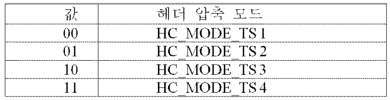
HC_MODE_IP: 해당 2비트 필드는 DP_PAYLOAD_TYPE이 IP ('01')로 설정되는 경우에 IP 헤더 압축 모드를 나타낸다. HC_MODE_IP는 아래의 표 26에 따라 시그널링 된다.HC_MODE_IP: The corresponding 2-bit field indicates the IP header compression mode when DP_PAYLOAD_TYPE is set to IP ('01'). HC_MODE_IP is signaled according to Table 26 below.

PID: 해당 13비트 필드는 DP_PAYLOAD_TYPE이 TS ('00')로 설정되고 HC_MODE_TS가 01 또는 10으로 설정되는 경우에 TS 헤더 압축을 위한 PID 수를 나타낸다.PID: The corresponding 13-bit field indicates the number of PIDs for TS header compression when DP_PAYLOAD_TYPE is set to TS ('00') and HC_MODE_TS is set to 01 or 10.
RESERVED: 해당 8비트 필드는 추후 사용을 위해 리저브드(reserved)된다.RESERVED: The corresponding 8-bit field is reserved for future use.
다음 필드는 FIC_FLAG가 1과 동일할 때만 나타난다.The following fields appear only when FIC_FLAG is equal to 1.
FIC_VERSION: 해당 8비트 필드는 FIC의 버전 넘버를 나타낸다.FIC_VERSION: The corresponding 8-bit field indicates the version number of the FIC.
FIC_LENGTH_BYTE: 해당 13비트 필드는 FIC의 길이를 바이트 단위로 나타낸다.FIC_LENGTH_BYTE: The corresponding 13-bit field indicates the length of the FIC in bytes.
RESERVED: 해당 8비트 필드는 추후 사용을 위해 리저브드(reserved)된다.RESERVED: The corresponding 8-bit field is reserved for future use.
다음 필드는 AUX_FLAG가 1과 동일할 때만 나타난다.The following fields appear only when AUX_FLAG is equal to 1.
NUM_AUX: 해당 4비트 필드는 보조 스트림의 수를 나타낸다. 제로는 보조 스트림이 사용되지 않는 것을 나타낸다.NUM_AUX: The corresponding 4-bit field indicates the number of auxiliary streams. Zero indicates that the auxiliary stream is not used.
AUX_CONFIG_RFU: 해당 8비트 필드는 추후 사용을 위해 리저브드(reserved)된다.AUX_CONFIG_RFU: The corresponding 8-bit field is reserved for future use.
AUX_STREAM_TYPE: 해당 4비트는 현 보조 스트림의 타입을 나타내기 위한 추후 사용을 위해 리저브드(reserved)된다.AUX_STREAM_TYPE: The corresponding 4 bits are reserved for future use to indicate the type of the current auxiliary stream.
AUX_PRIVATE_CONFIG: 해당 28비트 필드는 보조 스트림을 시그널링 하기 위한 추후 사용을 위해 리저브드(reserved)된다.AUX_PRIVATE_CONFIG: The corresponding 28-bit field is reserved for future use to signal the secondary stream.
도 15는 본 발명의 다른 일 실시예에 따른 PLS2 데이터를 나타낸다.15 shows PLS2 data according to another embodiment of the present invention.
도 15는 PLS2 데이터의 PLS2-DYN을 나타낸다. PLS2-DYN 데이터의 값은 하나의 프레임 그룹의 듀레이션 동안 변화할 수 있는 반면, 필드의 사이즈는 일정하다.15 shows PLS2-DYN of PLS2 data. The value of the PLS2-DYN data can vary during the duration of one frame group, while the size of the field is constant.
PLS2-DYN 데이터의 필드의 구체적인 내용은 다음과 같다.The specific contents of the PLS2-DYN data field are as follows.
FRAME_INDEX: 해당 5비트 필드는 슈퍼 프레임 내에서 현 프레임의 프레임 인덱스를 나타낸다. 슈퍼 프레임의 첫 번째 프레임의 인덱스는 0으로 설정된다.FRAME_INDEX: The corresponding 5-bit field indicates the frame index of the current frame in the superframe. The index of the first frame of the superframe is set to zero.
PLS_CHANGE_COUNTER: 해당 4비트 필드는 구성이 변화하기 전의 슈퍼 프레임의 수를 나타낸다. 구성이 변화하는 다음 슈퍼 프레임은 해당 필드 내에서 시그널링 되는 값에 의해 나타낸다. 해당 필드의 값이 0000으로 설정되면, 이는 어떠한 예정된 변화도 예측되지 않는 것을 의미한다. 예를 들면, 1의 값은 다음 슈퍼 프레임에 변화가 있다는 것을 나타낸다.PLS_CHANGE_COUNTER: The corresponding 4-bit field indicates the number of superframes before the configuration changes. The next superframe whose configuration changes is indicated by the value signaled within that field. If the value of the field is set to 0000, this means that no predetermined change is predicted. For example, a value of 1 indicates that there is a change in the next superframe.
FIC_CHANGE_COUNTER: 해당 4비트 필드는 구성(즉, FIC의 콘텐츠)이 변화하기 전의 슈퍼 프레임의 수를 나타낸다. 구성이 변화하는 다음 슈퍼 프레임은 해당 필드 내에서 시그널링 되는 값에 의해 나타낸다. 해당 필드의 값이 0000으로 설정되면, 이는 어떠한 예정된 변화도 예측되지 않는 것을 의미한다. 예를 들면, 0001의 값은 다음 슈퍼 프레임에 변화가 있다는 것을 나타낸다.FIC_CHANGE_COUNTER: The corresponding 4-bit field indicates the number of superframes before the configuration (i.e., content of the FIC) changes. The next superframe whose configuration changes is indicated by the value signaled within that field. If the value of the field is set to 0000, this means that no predetermined change is predicted. For example, a value of 0001 indicates that there is a change in the next superframe.
RESERVED: 해당 16비트 필드는 추후 사용을 위해 리저브드(reserved)된다.RESERVED: The corresponding 16-bit field is reserved for future use.
다음 필드는 현 프레임에서 전달되는 데이터 파이프와 관련된 파라미터를 설명하는 NUM_DP에서의 루프(loop)에 나타난다.The next field appears in the loop at NUM_DP, which describes the parameters associated with the datapipe passed in the current frame.
DP_ID: 해당 6비트 필드는 피지컬 프로파일 내에서 데이터 파이프를 유일하게 나타낸다.DP_ID: The corresponding 6-bit field uniquely represents the data pipe within the physical profile.
DP_START: 해당 15비트 (또는 13비트) 필드는 DPU 어드레싱(addressing) 기법을 사용하여 데이터 파이프의 첫 번째의 시작 위치를 나타낸다. DP_START 필드는 아래의 표 27에 나타낸 바와 같이 피지컬 프로파일 및 FFT 사이즈에 따라 다른 길이를 갖는다.DP_START: The corresponding 15-bit (or 13-bit) field indicates the start position of the first data pipe using the DPU addressing scheme. The DP_START field has a different length depending on the physical profile and FFT size as shown in Table 27 below.

DP_NUM_BLOCK: 해당 10비트 필드는 현 데이터 파이프에 대한 현 타임 인터리빙 그룹에서 FEC 블록의 수를 나타낸다. DP_NUM_BLOCK의 값은 0에서 1023 사이에 있다.DP_NUM_BLOCK: The corresponding 10-bit field indicates the number of FEC blocks in the current time interleaving group for the current data pipe. The value of DP_NUM_BLOCK is between 0 and 1023.
RESERVED: 해당 8비트 필드는 추후 사용을 위해 리저브드(reserved)된다.RESERVED: The corresponding 8-bit field is reserved for future use.
다음의 필드는 EAC와 관련된 FIC 파라미터를 나타낸다.The following fields represent the FIC parameters associated with the EAC.
EAC_FLAG: 해당 1비트 필드는 현 프레임에서 EAC의 존재를 나타낸다. 해당 비트는 프리앰블에서 EAC_FLAG와 같은 값이다.EAC_FLAG: The corresponding 1-bit field indicates the presence of an EAC in the current frame. The corresponding bit is the same value as EAC_FLAG in the preamble.
EAS_WAKE_UP_VERSION_NUM: 해당 8비트 필드는 자동 활성화 지시의 버전 넘버를 나타낸다.EAS_WAKE_UP_VERSION_NUM: The corresponding 8-bit field indicates the version number of the automatic activation instruction.
EAC_FLAG 필드가 1과 동일하면, 다음의 12비트가 EAC_LENGTH_BYTE 필드에 할당된다. EAC_FLAG 필드가 0과 동일하면, 다음의 12비트가 EAC_COUNTER에 할당된다.If the EAC_FLAG field is equal to 1, the next 12 bits are assigned to the EAC_LENGTH_BYTE field. If the EAC_FLAG field is equal to 0, the next 12 bits are assigned to EAC_COUNTER.
EAC_LENGTH_BYTE: 해당 12비트 필드는 EAC의 길이를 바이트로 나타낸다.EAC_LENGTH_BYTE: The corresponding 12-bit field indicates the length of the EAC in bytes.
EAC_COUNTER: 해당 12비트 필드는 EAC가 도달하는 프레임 전의 프레임의 수를 나타낸다.EAC_COUNTER: The corresponding 12-bit field indicates the number of frames before the frame reached by the EAC.
다음 필드는 AUX_FLAG 필드가 1과 동일한 경우에만 나타난다.The following fields appear only if the AUX_FLAG field is equal to 1.
AUX_PRIVATE_DYN: 해당 48비트 필드는 보조 스트림을 시그널링 하기 위한 추후 사용을 위해 리저브드(reserved)된다. 해당 필드의 의미는 설정 가능한 PLS2-STAT에서 AUX_STREAM_TYPE의 값에 의존한다.AUX_PRIVATE_DYN: The corresponding 48-bit field is reserved for future use to signal the auxiliary stream. The meaning of the field depends on the value of AUX_STREAM_TYPE in the configurable PLS2-STAT.
CRC_32: 전체 PLS2에 적용되는 32비트 에러 검출 코드.CRC_32: 32-bit error detection code applied to entire PLS2.
도 16은 본 발명의 일 실시예에 따른 프레임의 로지컬(logical) 구조를 나타낸다.16 shows a logical structure of a frame according to an embodiment of the present invention.
전술한 바와 같이, PLS, EAC, FIC, 데이터 파이프, 보조 스트림, 더미 셀은 프레임에서 OFDM 심볼의 액티브(active) 캐리어에 매핑된다. PLS1 및 PLS2는 처음에 하나 이상의 FSS에 매핑된다. 그 후, EAC가 존재한다면 EAC 셀은 바로 뒤따르는 PLS 필드에 매핑된다. 다음에 FIC가 존재한다면 FIC 셀이 매핑된다. 데이터 파이프는 PLS 다음에 매핑되거나, EAC 또는 FIC가 존재하는 경우, EAC 또는 FIC 이후에 매핑된다. 타입 1 데이터 파이프가 처음에 매핑되고, 타입 2 데이터 파이프가 다음에 매핑된다. 데이터 파이프의 타입의 구체적인 내용은 후술한다. 일부 경우, 데이터 파이프는 EAS에 대한 일부 특수 데이터 또는 서비스 시그널링 데이터를 전달할 수 있다. 보조 스트림 또는 스트림은 존재한다면 데이터 파이프를 다음에 매핑되고 여기에는 차례로 더미 셀이 뒤따른다. 전술한 순서, 즉, PLS, EAC, FIC, 데이터 파이프, 보조 스트림, 및 더미 셀의 순서로 모두 함께 매핑하면 프레임에서 셀 용량을 정확히 채운다.As described above, the PLS, EAC, FIC, data pipe, auxiliary stream, and dummy cells are mapped to the active carrier of the OFDM symbol in the frame. PLS1 and PLS2 are initially mapped to one or more FSSs. Thereafter, if there is an EAC, the EAC cell is mapped to the immediately following PLS field. The next time the FIC is present, the FIC cell is mapped. The data pipe is mapped after PLS, or after EAC or FIC if EAC or FIC is present. The
도 17은 본 발명의 일 실시예에 따른 PLS 매핑을 나타낸다.Figure 17 illustrates a PLS mapping in accordance with an embodiment of the present invention.
PLS 셀은 FSS의 액티브(active) 캐리어에 매핑된다. PLS가 차지하는 셀의 수에 따라, 하나 이상의 심볼이 FSS로 지정되고, FSS의 수 NFSS는 PLS1에서의 NUM_FSS에 의해 시그널링된다. FSS는 PLS 셀을 전달하는 특수한 심볼이다. 경고성 및 지연 시간(latency)은 PLS에서 중대한 사안이므로, FSS는 높은 파일럿 밀도를 가지고 있어 고속 동기화 및 FSS 내에서의 주파수만의 인터폴레이션(interpoloation, 보간)을 가능하게 한다.The PLS cell is mapped to the active carrier of the FSS. Depending on the number of cells occupied by the PLS, one or more symbols are designated as FSS, and the number of FSSs NFSS is signaled by NUM_FSS in PLS1. FSS is a special symbol that carries a PLS cell. Alerting and latency are critical issues in PLS, so FSS has high pilot density and enables high-speed synchronization and interpolation of only frequencies within the FSS.
PLS 셀은 도 17의 예에 나타낸 바와 같이 하향식으로 FSS의 액티브(active) 캐리어에 매핑된다. PLS1 셀은 처음에 첫 FSS의 첫 셀부터 셀 인덱스의 오름차순으로 매핑된다. PLS2 셀은 PLS1의 마지막 셀 직후에 뒤따르고, 매핑은 첫 FSS의 마지막 셀 인덱스까지 아래방향으로 계속된다. 필요한 PLS 셀의 총 수가 하나의 FSS의 액티브(active) 캐리어의 수를 초과하면, 매핑은 다음 FSS로 진행되고 첫 FSS와 완전히 동일한 방식으로 계속된다.The PLS cell is mapped to an active carrier of the FSS in a top-down manner as shown in the example of FIG. The PLS1 cell is initially mapped to the cell index in ascending order from the first cell of the first FSS. The PLS2 cell follows immediately after the last cell of PLS1 and the mapping continues down to the last cell index of the first FSS. If the total number of PLS cells required exceeds the number of active carriers in one FSS, the mapping proceeds to the next FSS and continues in exactly the same way as the first FSS.
PLS 매핑이 완료된 후, 데이터 파이프가 다음에 전달된다. EAC, FIC 또는 둘 다 현 프레임에 존재하면, EAC 및 FIC는PLS와 노멀 데이터 파이프 사이에 배치된다.After the PLS mapping is complete, the datapipe is delivered next. If EAC, FIC, or both are present in the current frame, the EAC and FIC are placed between the PLS and the normal data pipe.
도 18은 본 발명의 일 실시예에 따른 EAC 매핑을 나타낸다.18 shows an EAC mapping according to an embodiment of the present invention.
EAC는 EAS 메시지를 전달하는 전용 채널이고 EAS에 대한 데이터 파이프에 연결된다. EAS 지원은 제공되지만, EAC 자체는 모든 프레임에 존재할 수도 있고 존재하지 않을 수도 있다. EAC가 존재하는 경우, EAC는 PLS2 셀의 직후에 매핑된다. PLS 셀을 제외하고 FIC, 데이터 파이프, 보조 스트림 또는 더미 셀 중 어느 것도 EAC 앞에 위치하지 않는다. EAC 셀의 매핑 절차는 PLS와 완전히 동일하다.The EAC is a dedicated channel for delivering EAS messages and is connected to a data pipe for EAS. EAS support is provided, but the EAC itself may or may not be present in every frame. If an EAC is present, the EAC is mapped immediately after the PLS2 cell. None of the FIC, datapipe, auxiliary stream, or dummy cell except the PLS cell is located before the EAC. The mapping procedure of the EAC cell is exactly the same as the PLS.
EAC 셀은 도 18의 예에 나타낸 바와 같이 PLS2의 다음 셀부터 셀 인덱스의 오름차순으로 매핑된다. EAS 메시지 크기에 따라, 도 18에 나타낸 바와 같이 EAC 셀은 적은 심볼을 차지할 수 있다.The EAC cell is mapped in ascending order of the cell index from the next cell of PLS2 as shown in the example of Fig. Depending on the size of the EAS message, the EAC cell may occupy a small number of symbols, as shown in Fig.
EAC 셀은 PLS2의 마지막 셀 직후에 뒤따르고, 매핑은 마지막 FSS의 마지막 셀 인덱스까지 아래방향으로 계속된다. 필요한 EAC 셀의 총 수가 마지막 FSS의 남아 있는 액티브(active) 캐리어의 수를 초과하면, EAC 매핑은 다음 심볼로 진행되며, FSS와 완전히 동일한 방식으로 계속된다. 이 경우 EAC의 매핑이 이루어지는 다음 심볼은 노멀 데이터 심볼이고, 이는 FSS보다 더 많은 액티브(active) 캐리어를 갖는다.The EAC cell follows immediately after the last cell of PLS2 and the mapping continues down to the last cell index of the last FSS. If the total number of required EAC cells exceeds the number of remaining active carriers in the last FSS, the EAC mapping proceeds to the next symbol and continues in exactly the same way as the FSS. In this case, the next symbol to which the mapping of the EAC is made is the normal data symbol, which has more active carriers than the FSS.
EAC 매핑이 완료된 후, 존재한다면 FIC가 다음에 전달된다. FIC가 전송되지 않으면(PLS2 필드에서 시그널링으로), 데이터 파이프가 EAC의 마지막 셀 직후에 뒤따른다.After the EAC mapping is complete, the FIC is delivered next if it exists. If the FIC is not transmitted (with signaling in the PLS2 field), the data pipe follows immediately after the last cell of the EAC.
도 19는 본 발명의 일 실시예에 따른 FIC 매핑을 나타낸다.19 shows an FIC mapping according to an embodiment of the present invention.
(a)는 EAC 없이 FIC 셀의 매핑의 예를 나타내고, (b)는 EAC와 함께 FIC 셀의 매핑의 예를 나타낸다.(a) shows an example of a FIC cell mapping without an EAC, and (b) shows an example of a FIC cell mapping together with an EAC.
FIC는 고속 서비스 획득 및 채널 스캔을 가능하게 하기 위해 계층간 정보(cross-layer information)를 전달하는 전용 채널이다. 해당 정보는 주로 데이터 파이프 사이의 채널 바인딩 (channel binding) 정보 및 각 방송사의 서비스를 포함한다. 고속 스캔을 위해, 수신기는 FIC를 디코딩하고 방송사 ID, 서비스 수, BASE_DP_ID와 같은 정보를 획득할 수 있다. 고속 서비스 획득을 위해, FIC뿐만 아니라 베이스 데이터 파이프도 BASE_DP_ID를 이용해서 디코딩 될 수 있다. 베이스 데이터 파이프가 전송하는 콘텐트를 제외하고, 베이스 데이터 파이프는 노멀 데이터 파이프와 정확히 동일한 방식으로 인코딩되어 프레임에 매핑된다. 따라서, 베이스 데이터 파이프에 대한 추가 설명이 필요하지 않다. FIC 데이터가 생성되어 관리 계층에서 소비된다. FIC 데이터의 콘텐트는 관리 계층 사양에 설명된 바와 같다.The FIC is a dedicated channel that delivers cross-layer information to enable fast service acquisition and channel scanning. This information mainly includes channel binding information between data pipes and service of each broadcaster. For fast scanning, the receiver can decode the FIC and obtain information such as the broadcaster ID, number of services, and BASE_DP_ID. For fast service acquisition, not only the FIC but also the base data pipe can be decoded using BASE_DP_ID. Except for the content that the base data pipe transmits, the base data pipe is encoded and mapped to the frame in exactly the same way as the normal data pipe. Therefore, no further description of the base data pipe is required. FIC data is generated and consumed in the management layer. The content of the FIC data is as described in the management layer specification.
FIC 데이터는 선택적이고, FIC의 사용은 PLS2의 스태틱(static, 정적)인 부분에서 FIC_FLAG 파라미터에 의해 시그널링 된다. FIC가 사용되면, FIC_FLAG는 1로 설정되고, FIC에 대한 시그널링 필드는 PLS2의 스태틱(static, 정적)인 부분에서 정의된다. 해당 필드에서 시그널링되는 것은 FIC_VERSION이고, FIC_LENGTH_BYTE. FIC는 PLS2와 동일한 변조, 코딩, 타임 인터리빙 파라미터를 사용한다. FIC는 PLS2_MOD 및 PLS2_FEC와 같은 동일한 시그널링 파라미터를 공유한다. FIC 데이터는 존재한다면 PLS2 후에 매핑되거나, EAC가 존재하는 경우 EAC 직후에 매핑된다. 노멀 데이터 파이프, 보조 스트림, 또는 더미 셀 중 어느 것도 FIC 앞에 위치하지 않는다. FIC 셀을 매핑하는 방법은 EAC와 완전히 동일하고, 이는 다시 PLS와 동일하다.The FIC data is optional, and the use of FIC is signaled by the FIC_FLAG parameter in the static (static) portion of PLS2. If FIC is used, FIC_FLAG is set to 1, and the signaling field for FIC is defined in the static (static) portion of PLS2. Signed in the field is FIC_VERSION, and FIC_LENGTH_BYTE. FIC uses the same modulation, coding, and time interleaving parameters as PLS2. The FIC shares the same signaling parameters such as PLS2_MOD and PLS2_FEC. The FIC data is mapped after PLS2 if present, or immediately after EAC if EAC is present. Neither the normal data pipe, the auxiliary stream nor the dummy cell is located before the FIC. The method of mapping the FIC cell is exactly the same as the EAC, which is the same as PLS.
PLS 후의 EAC가 존재하지 않는 경우, FIC 셀은 (a)의 예에 나타낸 바와 같이 PLS2의 다음 셀부터 셀 인덱스의 오름차순으로 매핑된다. FIC 데이터 사이즈에 따라, (b)에 나타낸 바와 같이, FIC 셀은 수 개의 심볼에 대해서 매핑된다.If there is no EAC after PLS, the FIC cell is mapped to the ascending cell index from the next cell of PLS2 as shown in the example of (a). Depending on the FIC data size, as shown in (b), the FIC cell is mapped for several symbols.
FIC 셀은 PLS2의 마지막 셀 직후에 뒤따르고, 매핑은 마지막 FSS의 마지막 셀 인덱스까지 아래방향으로 계속된다. 필요한 FIC 셀의 총 수가 마지막 FSS의 남아 있는 액티브(active) 캐리어의 수를 초과하면, 나머지 FIC 셀의 매핑은 다음 심볼로 진행되며 이는 FSS와 완전히 동일한 방식으로 계속된다. 이 경우, FIC가 매핑되는 다음 심볼은 노멀 데이터 심볼이며, 이는 FSS보다 더 많은 액티브(active) 캐리어를 갖는다.The FIC cell follows immediately after the last cell of PLS2 and the mapping continues down to the last cell index of the last FSS. If the total number of FIC cells required exceeds the number of remaining active carriers in the last FSS, the mapping of the remaining FIC cells proceeds to the next symbol, which continues in exactly the same way as the FSS. In this case, the next symbol to which the FIC is mapped is a normal data symbol, which has more active carriers than the FSS.
EAS 메시지가 현 프레임에서 전송되면, EAC는 FIC 보다 먼저 매핑되고 (b)에 나타낸 바와 같이 EAC의 다음 셀부터 FIC 셀은 셀 인덱스의 오름차순으로 매핑된다.When the EAS message is transmitted in the current frame, the EAC is mapped earlier than the FIC, and the FIC cells from the next cell of the EAC are mapped in ascending order of the cell index as shown in (b).
FIC 매핑이 완료된 후, 하나 이상의 데이터 파이프가 매핑되고, 이후 존재한다면 보조 스트림, 더미 셀이 뒤따른다.After the FIC mapping is completed, one or more data pipes are mapped, followed by an auxiliary stream, a dummy cell if present.
도 20은 본 발명의 일 실시예에 따른 데이터 파이프의 타입을 나타낸다.20 shows a type of data pipe according to an embodiment of the present invention.
(a)는 타입 1 데이터 파이프를 나타내고, (b)는 타입 2 데이터 파이프를 나타낸다.(a) shows a
선행하는 채널, 즉 PLS, EAC, FIC가 매핑된 후, 데이터 파이프의 셀이 매핑된다. 데이터 파이프는 매핑 방법에 따라 두 타입 중 하나로 분류된다.After the preceding channels, PLS, EAC, FIC, are mapped, cells of the data pipe are mapped. Data pipes are classified into one of two types according to the mapping method.
타입 1 데이터 파이프: 데이터 파이프가 TDM에 의해 매핑된다.
타입 2 데이터 파이프: 데이터 파이프가 FDM에 의해 매핑된다.
데이터 파이프의 타입은 PLS2의 스태틱(static, 정적)인 부분에서 DP_TYPE 필드에 의해 나타낸다. 도 20은 타입 1 데이터 파이프 및 타입 2 데이터 파이프의 매핑 순서를 나타낸다. 타입 1 데이터 파이프는 우선 셀 인덱스의 오름차순으로 매핑된 후, 마지막 셀 인덱스에 도달한 후, 심볼 인덱스가 1씩 증가된다. 다음 심볼 내에서, 데이터 파이프는 p = 0을 시작으로 셀 인덱스의 오름차순으로 계속 매핑된다. 하나의 프레임에서 함께 매핑되는 다수의 데이터 파이프와 함께, 각각의 타입 1 데이터 파이프는 데이터 파이프의 TDM과 유사하게 시간으로 그루핑된다.The type of datapipe is indicated by the DP_TYPE field in the static (static) portion of PLS2. Figure 20 shows the mapping order of
타입 2 데이터 파이프는 우선 심볼 인덱스의 오름차순으로 매핑되고, 프레임의 마지막 OFDM 심볼에 도달한 후, 셀 인덱스는 1씩 증가하고, 심볼 인덱스는 첫 번째 가용 심볼로 되돌아 간 후, 그 심볼 인덱스부터 증가한다. 하나의 프레임에서 다수의 데이터 파이프를 매핑한 후, 각각의 타입 2 데이터 파이프는 데이터 파이프의 FDM과 유사하게 주파수로 그루핑된다.The
타입 1 데이터 파이프 및 타입 2 데이터 파이프는 필요시 프레임에서 공존할 수 있는데, 타입 1 데이터 파이프가 항상 타입 2 데이터 파이프에 선행한다는 제한이 있다. 타입 1 및 타입 2 데이터 파이프를 전달하는 OFDM 셀의 총 수는 데이터 파이프의 전송에 사용할 수 있는 OFDM 셀의 총 수를 초과할 수 없다.
![]()
![]()
이때, DDP1는 타입 1 데이터 파이프가 차지하는 OFDM 셀의 수에 해당하고, DDP2는 타입 2 데이터 파이프가 차지하는 셀의 수에 해당한다. PLS, EAC, FIC가 모두 타입 1 데이터 파이프와 마찬가지 방식으로 매핑되므로, PLS, EAC, FIC는 모두 "타입 1 매핑 규칙"에 따른다. 따라서, 대체로 타입 1 매핑이 항상 타입 2 매핑에 선행한다.At this time, D DP1 corresponds to the number of OFDM cells occupied by the
도 21은 본 발명의 일 실시예에 따른 데이터 파이프 매핑을 나타낸다.21 shows a data pipe mapping according to an embodiment of the present invention.
(a)는 타입 1 데이터 파이프를 매핑하기 위한 OFDM 셀의 어드레싱을 나타내고, (b)는 타입 2 데이터 파이프를 매핑하기 위한 OFDM 셀의 어드레싱을 나타낸다.(a) shows the addressing of the OFDM cell for mapping the
타입 1 데이터 파이프(0, ..., DDP1-1)를 매핑하기 위한 OFDM 셀의 어드레싱은 타입 1 데이터 파이프의 액티브(active) 데이터 셀에 대해 정의된다. 어드레싱 방식은 각각의 타입 1 데이터 파이프에 대한 타임 인터리빙으로부터의 셀이 액티브(active) 데이터 셀에 할당되는 순서를 정의한다. 어드레싱 방식은 또한 PLS2의 다이나믹(dynamic, 동적) 부분에서 데이터 파이프의 위치를 시그널링 하는 데 사용된다.The addressing of the OFDM cells for mapping the
EAC 및 FIC 없이, 어드레스 0은 마지막 FSS에서 PLS를 전달하는 마지막 셀에 바로 뒤따르는 셀을 말한다. EAC가 전송되고, FIC가 해당하는 프레임에 없으면, 어드레스 0은 EAC를 전달하는 마지막 셀에 바로 뒤따르는 셀을 말한다. FIC가 해당하는 프레임에서 전송되면, 어드레스 0은 FIC를 전달하는 마지막 셀에 바로 뒤따르는 셀을 말한다. 타입 1 데이터 파이프에 대한 어드레스 0은 (a)에 나타낸 바와 같은 두 가지 서로 다른 경우를 고려해서 산출될 수 있다. (a)의 예에서, PLS, EAC, FIC는 모두 전송된다고 가정한다. EAC와 FIC 중 하나 또는 모두가 생략되는 경우로의 확장은 자명하다. (a)의 좌측에 나타낸 바와 같이 FIC까지 모든 셀을 매핑한 후에 FSS에 남아 있는 셀이 있으면.Without EAC and FIC,
타입 2 데이터 파이프(0, ..., DDP2-1)를 매핑하기 위한 OFDM 셀의 어드레싱은 타입 2 데이터 파이프의 액티브(active) 데이터 셀에 대해 정의된다. 어드레싱 방식은 각각의 타입 2 데이터 파이프에 대한 타임 인터리빙으로부터의 셀이 액티브(active) 데이터 셀에 할당되는 순서를 정의한다. 어드레싱 방식은 또한 PLS2의 다이나믹(dynamic, 동적) 부분에서 데이터 파이프의 위치를 시그널링 하는 데 사용된다.The addressing of the OFDM cell for mapping the
(b)에 나타낸 바와 같이, 세 가지 약간 다른 경우가 가능하다. (b)의 좌측에 나타낸 첫 번째 경우에, 마지막 FSS에 있는 셀은 타입 2 데이터 파이프 매핑에 사용될 수 있다. 중앙에 나타낸 두 번째 경우에, FIC는 노멀 심볼의 셀을 차지하지만, 해당 심볼에서의 FIC 셀의 수는 CFSS보다 크지 않다. (b)의 우측에 나타낸 세 번째 경우는 해당 심볼에 매핑된 FIC 셀의 수가 CFSS를 초과한다는 점을 제외하고 두 번째 경우와 동일하다.(b), three slightly different cases are possible. In the first case shown on the left side of (b), the cell in the last FSS can be used for
PLS, EAC, FIC가 타입 1 데이터 파이프와 동일한 "타입 1 매핑 규칙"에 따르므로, 타입 1 데이터 파이프가 타입 2 데이터 파이프에 선행하는 경우로의 확장은 자명하다.Since PLS, EAC, and FIC follow the same "
데이터 파이프 유닛(DPU)은 프레임에서 데이터 셀을 데이터 파이프에 할당하는 기본 단위이다.A data pipe unit (DPU) is a basic unit for assigning data cells to data pipes in a frame.
DPU는 프레임에서 데이터 파이프의 위치를 찾아내기 위한 시그널링 단위로 정의된다. 셀 매퍼(7010)는 각각의 데이터 파이프에 대해 타임 인터리빙에 의해 생성된 셀을 매핑할 수 있다. 타임 인터리버(5050)는 일련의 타임 인터리빙 블록을 출력하고, 각각의 타임 인터리빙 블록은 XFECBLOCK의 가변 수를 포함하고, 이는 결국 셀의 집합으로 구성된다. XFECBLOCK에서의 셀의 수 Ncells는 FECBLOCK 사이즈, Nldpc, 컨스텔레이션 심볼당 전송되는 비트 수에 의존한다. DPU는 주어진 피지컬 프로파일에서 지원되는 XFECBLOCK에서의 셀의 수 Ncells의 모든 가능한 값의 최대 공약수로 정의된다. 셀에서의 DPU의 길이는 LDPU로 정의된다. 각각의 피지컬 프로파일은 FECBLOCK 사이즈의 서로 다른 조합 및 컨스텔레이션 심볼당 다른 비트 수를 지원하므로, LDPU는 피지컬 프로파일을 기초로 정의된다.The DPU is defined as a signaling unit for locating a data pipe in a frame. The
도 22는 본 발명의 일 실시예에 따른 FEC 구조를 나타낸다.22 shows an FEC structure according to an embodiment of the present invention.
도 22는 비트 인터리빙 전의 본 발명의 일 실시예에 따른 FEC 구조를 나타낸다. 전술한 바와 같이, 데이터 FEC 인코더는 외부 코딩(BCH) 및 내부 코딩(LDPC)을 이용하여 FECBLOCK 절차를 생성하기 위해 입력 BBF에 FEC 인코딩을 실행할 수 있다. 도시된 FEC 구조는 FECBLOCK에 해당한다. 또한, FECBLOCK 및 FEC 구조는 LDPC 코드워드의 길이에 해당하는 동일한 값을 갖는다.22 shows an FEC structure according to an embodiment of the present invention before bit interleaving. As described above, the data FEC encoder may perform FEC encoding on the input BBF to generate the FECBLOCK procedure using outer coding (BCH) and inner coding (LDPC). The FEC structure shown corresponds to FECBLOCK. In addition, the FEC BLOCK and FEC structures have the same value corresponding to the length of the LDPC code word.
도 22에 도시된 바와 같이, BCH 인코딩이 각각의 BBF(Kbch 비트)에 적용된 후, LDPC 인코딩이 BCH - 인코딩된 BBF(Kldpc 비트 = Nbch 비트)에 적용된다.As shown in FIG. 22, after the BCH encoding is applied to each BBF (K bch bit), LDPC encoding is applied to the BCH-encoded BBF (K ldpc bit = N bch bit).
Nldpc의 값은 64800 비트 (롱 FECBLOCK) 또는 16200 비트 (쇼트 FECBLOCK)이다.The value of N ldpc is 64800 bits (long FECBLOCK) or 16200 bits (short FECBLOCK).
아래의 표 28 및 표 29는 롱 FECBLOCK 및 쇼트 FECBLOCK 각각에 대한 FEC 인코딩 파라미터를 나타낸다.Tables 28 and 29 below show FEC encoding parameters for long FECBLOCK and short FECBLOCK, respectively.


BCH 인코딩 및 LDPC 인코딩의 구체적인 동작은 다음과 같다.Specific operations of the BCH encoding and the LDPC encoding are as follows.
12-에러 정정 BCH 코드가 BBF의 외부 인코딩에 사용된다. 쇼트 FECBLOCK 및 롱 FECBLOCK에 대한 BBF 생성 다항식은 모든 다항식을 곱함으로써 얻어진다.12-error correction BCH code is used for external encoding of BBF. The BBF generator polynomial for short FECBLOCK and long FECBLOCK is obtained by multiplying all polynomials.
LDPC 코드는 외부 BCH 인코딩의 출력을 인코딩하는 데 사용된다. 완성된 Bldpc (FECBLOCK)를 생성하기 위해, Pldpc (패리티 비트)가 각각의 Ildpc (BCH - 인코딩된 BBF)로부터 조직적으로 인코딩되고, Ildpc에 첨부된다. 완성된 Bldpc (FECBLOCK)는 다음의 수학식으로 표현된다.The LDPC code is used to encode the output of the outer BCH encoding. To produce a finished B ldpc (FECBLOCK), ldpc P (parity bits) are each I ldpc - is systematically encoded from the (BCH encoded BBF), it is attached to the I ldpc. The finished B ldpc (FECBLOCK) is expressed by the following equation.
![]()
![]()
롱 FECBLOCK 및 쇼트 FECBLOCK에 대한 파라미터는 위의 표 28 및 29에 각각 주어진다.Parameters for long FECBLOCK and short FECBLOCK are given in Tables 28 and 29, respectively, above.
롱 FECBLOCK에 대해 Nldpc - Kldpc 패리티 비트를 계산하는 구체적인 절차는 다음과 같다.N ldpc for long FECBLOCK - specific procedures for calculating the K ldpc parity bits is as follows.
1) 패리티 비트 초기화1) Initialize the parity bit
![]()
![]()
2) 패리티 체크 매트릭스의 어드레스의 첫 번째 행에서 특정된 패리티 비트 어드레스에서 첫 번째 정보 비트 i0 누산(accumulate). 패리티 체크 매트릭스의 어드레스의 상세한 내용은 후술한다. 예를 들면, 비율 13/15에 대해,2) Accumulate the first information bit i 0 at the parity bit address specified in the first row of the address of the parity check matrix. The details of the address of the parity check matrix will be described later. For example, for a ratio of 13/15,

3) 다음 359개의 정보 비트 is, s=1, 2, ..., 359에 대해, 다음의 수학식을 이용하여 패리티 비트 어드레스에서 is 누산(accumulate).3) For the next 359 information bits i s , s = 1, 2, ..., 359, i s accumulate at the parity bit address using the following equation:
![]()
![]()
여기서, x는 첫 번째 비트 i0에 해당하는 패리티 비트 누산기의 어드레스를 나타내고, Qldpc는 패리티 체크 매트릭스의 어드레서에서 특정된 코드 레이트(code rate) 의존 상수이다. 상기 예인, 비율 13/15에 대한, 따라서 정보 비트 i1에 대한 Qldpc = 24에 계속해서, 다음 동작이 실행된다.Where x denotes the address of the parity bit accumulator corresponding to the first bit i 0 and Q ldpc is a code rate dependent constant specified in the address book of the parity check matrix. Following the above example, Q ldpc = 24 for the

4) 361번째 정보 비트 i360에 대해, 패리티 비트 누산기의 어드레스는 패리티 체크 매트릭스의 어드레스의 두 번째 행에 주어진다. 마찬가지 방식으로, 다음 359개의 정보 비트 is, s= 361, 362, ..., 719에 대한 패리티 비트 누산기의 어드레스는 수학식 6을 이용하여 얻어진다. 여기서, x는 정보 비트 i360에 해당하는 패리티 비트 누산기의 어드레스, 즉 패리티 체크 매트릭스의 두 번째 행의 엔트리를 나타낸다.4) For the 361st information bit i 360 , the address of the parity bit accumulator is given in the second row of the address of the parity check matrix. In a similar manner, the address of the parity bit accumulator for the next 359 information bits i s , s = 361, 362, ..., 719 is obtained using equation (6). Here, x represents the address of the parity bit accumulator corresponding to the information bit i 360 , i.e., the entry of the second row of the parity check matrix.
5) 마찬가지 방식으로, 360개의 새로운 정보 비트의 모든 그룹에 대해, 패리티 체크 매트릭스의 어드레스로부터의 새로운 행은 패리티 비트 누산기의 어드레스를 구하는 데 사용된다.5) Similarly, for all groups of 360 new information bits, a new row from the address of the parity check matrix is used to obtain the address of the parity bit accumulator.
모든 정보 비트가 이용된 후, 최종 패리티 비트가 다음과 같이 얻어진다.After all the information bits are used, the last parity bit is obtained as follows.
6) i=1로 시작해서 다음 동작을 순차적으로 실행6) Start with i = 1 and execute the next action sequentially
![]()
![]()
여기서 pi, i=0,1,...Nldpc - Kldpc - 1의 최종 콘텐트는 패리티 비트 pi와 동일하다.The final content of p i , i = 0,1, ... N ldpc - K ldpc - 1 is equal to the parity bit p i .

표 30을 표 31로 대체하고, 롱 FECBLOCK에 대한 패리티 체크 매트릭스의 어드레스를 쇼트 FECBLOCK에 대한 패리티 체크 매트릭스의 어드레스로 대체하는 것을 제외하고, 쇼트 FECBLOCK에 대한 해당 LDPC 인코딩 절차는 롱 FECBLOCK에 대한 t LDPC 인코딩 절차에 따른다.The corresponding LDPC encoding procedure for the short FECBLOCK is the same as the LDPC encoding for the short FECBLOCK except that it replaces Table 30 with Table 31 and replaces the address of the parity check matrix for the long FECBLOCK with the address of the parity check matrix for the short FECBLOCK. Encoding procedure.

도 23은 본 발명의 일 실시예에 따른 비트 인터리빙을 나타낸다.23 shows bit interleaving according to an embodiment of the present invention.
LDPC 인코더의 출력은 비트 인터리빙되는데, 이는 QCB (quasi-cyclic block) 인터리빙 및 내부 그룹 인터리빙이 뒤따르는 패리티 인터리빙으로 구성된다.The output of the LDPC encoder is bit interleaved, which consists of parity interleaving followed by quasi-cyclic block (QCB) interleaving and inner group interleaving.
(a)는 QCB 인터리빙을 나타내고, (b)는 내부 그룹 인터리빙을 나타낸다.(a) shows QCB interleaving, and (b) shows inner group interleaving.
FECBLOCK은 패리티 인터리빙될 수 있다. 패리티 인터리빙의 출력에서, LDPC 코드워드는 롱 FECBLOCK에서 180개의 인접하는 QCB으로 구성되고, 쇼트 FECBLOCK에서 45개의 인접하는 QCB으로 구성된다. 롱 또는 쇼트 FECBLOCK에서의 각각의 QCB는 360비트로 구성된다. 패리티 인터리빙된 LDPC 코드워드는 QCB 인터리빙에 의해 인터리빙된다. QCB 인터리빙의 단위는 QCB이다. 패리티 인터리빙의 출력에서의 QCB는 도 23에 나타낸 바와 같이 QCB 인터리빙에 의해 퍼뮤테이션되는데, 여기서 FECBLOCK 길이에 따라 Ncells = 64800/![]()
![]()
![]()
![]()
QCB 인터리빙 후에, 내부 그룹 인터리빙이 아래의 표 32에 정의된 변조 타입 및 차수(![]()
![]()

내부 그룹 인터리빙 과정은 QCB 인터리빙 출력의 NQCB_IG개의 QCB로 실행된다. 내부 그룹 인터리빙은 360개의 열 및 NQCB_IG개의 행을 이용해서 내부 그룹의 비트를 기입하고 판독하는 과정을 포함한다. 기입 동작에서, QCB 인터리빙 출력으로부터의 비트가 행 방향으로 기입된다. 판독 동작은 열 방향으로 실행되어 각 행에서 m개의 비트를 판독한다. 여기서 m은 NUC의 경우 1과 같고 NUQ의 경우 2와 같다.The inner group interleaving process is performed with N QCB_IG QCBs of the QCB interleaving output. Internal group interleaving involves writing and reading bits of the inner group using 360 columns and N QCB_IG rows. In a write operation, bits from the QCB interleaving output are written in the row direction. The read operation is performed in the column direction to read m bits in each row. Where m is equal to 1 for NUC and equal to 2 for NUQ.
도 24는 본 발명의 일 실시예에 따른 셀-워드 디멀티플렉싱을 나타낸다.24 illustrates cell-word demultiplexing in accordance with an embodiment of the present invention.
도 24에서, (a)는 8 및 12 bpcu MIMO에 대한 셀-워드 디멀티플렉싱을 나타내고, (b)는 10 bpcu MIMO에 대한 셀-워드 디멀티플렉싱을 나타낸다.In FIG. 24, (a) shows cell-word demultiplexing for 8 and 12 bpcu MIMO and (b) shows cell-word demultiplexing for 10 bpcu MIMO.
비트 인터리빙 출력의 각각의 셀 워드(c0,l, c1,l, ..., cnmod-1,l)는 하나의 XFECBLOCK에 대한 셀-워드 디멀티플렉싱 과정을 설명하는 (a)에 나타낸 바와 같이 (d1,0,m, d1,1,m..., d1,nmod-1,m) 및 (d2,0,m, d2,1,m..., d2,nmod-1,m)로 디멀티플렉싱된다.Each cell word (c 0, l , c 1, l , ..., c nmod-1, l ) of the bit interleaving output is represented by (a) as (d 1,0, m, d 1 , 1, m ...,
MIMO 인코딩을 위해 다른 타입의 NUQ를 이용하는 10 bpcu MIMO 경우에, NUQ-1024에 대한 비트 인터리버가 재사용된다. 비트 인터리버 출력의 각각의 셀 워드 (c0,l, c1,l, ..., c9,l)는 (b)에 나타낸 바와 같이 (d1,0,m, d1,1,m..., d1,3,m) 및 (d2,0,m, d2,1,m..., d2,5,m)로 디멀티플렉싱된다.In the case of 10 bpcu MIMO using another type of NUQ for MIMO encoding, the bit interleaver for NUQ-1024 is reused. A bit interleaver for each output cell word (c 0, l, c 1 , l, ...,
도 25는 본 발명의 일 실시예에 따른 타임 인터리빙을 나타낸다.25 shows time interleaving according to an embodiment of the present invention.
(a) 내지 (c)는 타임 인터리빙 모드의 예를 나타낸다.(a) to (c) show examples of a time interleaving mode.
타임 인터리버는 데이터 파이프 레벨에서 동작한다. 타임 인터리빙의 파라미터는 각각의 데이터 파이프에 대해 다르게 설정될 수 있다.The time interleaver operates at the datapipe level. The parameters of the time interleaving can be set differently for each data pipe.
PLS2-STAT 데이터의 일부에 나타나는 다음의 파라미터는 타임 인터리빙을 구성한다.The following parameters appearing in a portion of the PLS2-STAT data constitute time interleaving.
DP_TI_TYPE (허용된 값: 0 또는 1): 타임 인터리빙 모드를 나타낸다. 0은 타임 인터리빙 그룹당 다수의 타임 인터리빙 블록(하나 이상의 타임 인터리빙 블록)을 갖는 모드를 나타낸다. 이 경우, 하나의 타임 인터리빙 그룹은 하나의 프레임에 (프레임간 인터리빙 없이) 직접 매핑된다. 1은 타임 인터리빙 그룹당 하나의 타임 인터리빙 블록만을 갖는 모드를 나타낸다. 이 경우, 타임 인터리빙 블록은 하나 이상의 프레임에 걸쳐 확산된다(프레임간 인터리빙).DP_TI_TYPE (Allowed value: 0 or 1): Indicates the time interleaving mode. 0 represents a mode having a plurality of time interleaving blocks (one or more time interleaving blocks) per time interleaving group. In this case, one time interleaving group is directly mapped to one frame (without inter-frame interleaving). 1 represents a mode having only one time interleaving block per time interleaving group. In this case, the time interleaving block is spread over one or more frames (inter-frame interleaving).
DP_TI_LENGTH: DP_TI_TYPE = '0'이면, 해당 파라미터는 타임 인터리빙 그룹당 타임 인터리빙 블록의 수 NTI이다. DP_TI_TYPE = '1'인 경우, 해당 파라미터는 하나의 타임 인터리빙 그룹으로부터 확산되는 프레임의 수 PI이다.DP_TI_LENGTH: If DP_TI_TYPE = '0', the parameter is the number of time interleaving blocks N TI per time interleaving group. If DP_TI_TYPE = '1', the parameter is the number P I of frames spread from one time interleaving group.
DP_NUM_BLOCK_MAX (허용된 값: 0 내지 1023): 타임 인터리빙 그룹당 XFECBLOCK의 최대 수를 나타낸다.DP_NUM_BLOCK_MAX (Allowed values: 0 to 1023): This indicates the maximum number of XFECBLOCKs per time interleaving group.
DP_FRAME_INTERVAL (허용된 값: 1, 2, 4, 8): 주어진 피지컬 프로파일의 동일한 데이터 파이프를 전달하는 두 개의 순차적인 프레임 사이의 프레임의 수 IJUMP를 나타낸다.DP_FRAME_INTERVAL (Allowed values: 1, 2, 4, 8): Indicates the number of frames I JUMP between two sequential frames carrying the same datapipe of a given physical profile.
DP_TI_BYPASS (허용된 값: 0 또는 1): 타임 인터리빙이 데이터 프레임에 이용되지 않으면, 해당 파라미터는 1로 설정된다. 타임 인터리빙이 이용되면, 0으로 설정된다.DP_TI_BYPASS (Allowed value: 0 or 1): If time interleaving is not used in the data frame, the corresponding parameter is set to 1. If time interleaving is used, it is set to zero.
추가로, PLS2-DYN 데이터로부터의 파라미터 DP_NUM_BLOCK은 데이터 그룹의 하나의 타임 인터리빙 그룹에 의해 전달되는 XFECBLOCK의 수를 나타낸다.In addition, the parameter DP_NUM_BLOCK from the PLS2-DYN data represents the number of XFECBLOCKs carried by one time interleaving group of the data group.
타임 인터리빙이 데이터 프레임에 이용되지 않으면, 다음의 타임 인터리빙 그룹, 타임 인터리빙 동작, 타임 인터리빙 모드는 고려되지 않는다. 그러나 스케줄러부터의 다이나믹(dynamic, 동적) 구성 정보를 위한 딜레이 컴펜세이션(delay compensation, 지연보상) 블록은 여전히 필요하다. 각각의 데이터 파이프에서, SSD/MIMO 인코딩으로부터 수신한 XFECBLOCK은 타임 인터리빙 그룹으로 그루핑된다. 즉, 각각의 타임 인터리빙 그룹은 정수 개의 XFECBLOCK의 집합이고, 다이나믹(dynamic, 동적)으로 변화하는 수의 XFECBLOCK을 포함할 것이다. 인덱스 n의 타임 인터리빙 그룹에 있는 XFECBLOCK의 수는 NxBLOCK_Group(n)로 나타내고, PLS2-DYN 데이터에서 DP_NUM_BLOCK으로 시그널링된다. 이때, NxBLOCK_Group(n)은 최소값 0에서 가장 큰 값이 1023인 최대값 NxBLOCK_Group_MAX (DP_NUM_BLOCK_MAX에 해당)까지 변화할 수 있다.If time interleaving is not used for a data frame, the following time interleaving group, time interleaving operation, and time interleaving mode are not considered. However, delay compensation (delay compensation) blocks for the dynamic configuration information from the scheduler are still needed. In each data pipe, the XFECBLOCK received from the SSD / MIMO encoding is grouped into a time interleaving group. That is, each time interleaving group is a set of integer XFECBLOCKs and will contain a dynamic number of varying numbers of XFECBLOCKs. The number of XFECBLOCKs in the time interleaving group of index n is denoted by N xBLOCK_Group (n) and signaled by DP_NUM_BLOCK in PLS2-DYN data. At this time, N x BLOCK_Group (n) may change from a
각각의 타임 인터리빙 그룹은 하나의 프레임에 직접 매핑되거나 PI개의 프레임에 걸쳐 확산된다. 또한 각각의 타임 인터리빙 그룹은 하나 이상(NTI개)의 타임 인터리빙 블록으로 분리된다. 여기서 각각의 타임 인터리빙 블록은 타임 인터리버 메모리의 하나의 사용에 해당한다. 타임 인터리빙 그룹 내의 타임 인터리빙 블록은 약간의 다른 수의 XFECBLOCK을 포함할 수 있다. 타임 인터리빙 그룹이 다수의 타임 인터리빙 블록으로 분리되면, 타임 인터리빙 그룹은 하나의 프레임에만 직접 매핑된다. 아래의 표 33에 나타낸 바와 같이, 타임 인터리빙에는 세 가지 옵션이 있다(타임 인터리빙을 생략하는 추가 옵션 제외).Each time interleaving group is mapped directly to one frame or spread over P I frames. Each time interleaving group is separated into one or more (N TI ) time interleaving blocks. Where each time interleaving block corresponds to one use of a time interleaver memory. The time interleaving block in the time interleaving group may contain a slightly different number of XFECBLOCKs. If a time interleaving group is divided into a plurality of time interleaving blocks, a time interleaving group is directly mapped to only one frame. As shown in Table 33 below, there are three options for time interleaving (except for the additional option of omitting time interleaving).

각각의 데이터 파이프에서, 타임 인터리빙 메모리는 입력된 XFECBLOCK (SSD/MIMO 인코딩 블록으로부터 출력된 XFECBLOCK)을 저장한다. 입력된 XFECBLOCK은 ![]()
![]()
![]()
![]()

또한, 타임 인터리버(5050)로부터 출력된 XFECBLOCK은 ![]()
![]()
![]()
![]()
![]()
![]()
일반적으로, 타임 인터리버는 프레임 생성 과정 이전에 데이터 파이프 데이터에 대한 버퍼로도 작용할 것이다. 이는 각각의 데이터 파이프에 대해 2개의 메모리 뱅크로 달성된다. 첫 번째 타임 인터리빙 블록은 첫 번째 뱅크에 기입된다. 첫 번째 뱅크에서 판독되는 동안 두 번째 타임 인터리빙 블록이 두 번째 뱅크에 기입된다.In general, the time interleaver will also act as a buffer for data pipe data prior to the frame generation process. This is accomplished with two memory banks for each data pipe. The first time interleaving block is written to the first bank. A second time interleaving block is written to the second bank while being read in the first bank.
타임 인터리빙은 트위스트된 행-열 블록 인터리버이다. n번째 타임 인터리빙 그룹의 s번째 타임 인터리빙 블록에 대해, 열의 수 Nc가 ![]()
![]()
도 26은 본 발명의 일 실시예에 따른 트위스트된 행-열 블록 인터리버의 기본 동작을 나타낸다.26 illustrates a basic operation of a twisted row-column block interleaver in accordance with an embodiment of the present invention.
도 26(a)는 타임 인터리버에서 기입 동작을 나타내고, 도 26(b)는 타임 인터리버에서 판독 동작을 나타낸다. (a)에 나타낸 바와 같이, 첫 번째 XFECBLOCK은 타임 인터리빙 메모리의 첫 번째 열에 열 방향으로 기입되고, 두 번째 XFECBLOCK은 다음 열에 기입되고, 이러한 동작이 이어진다. 그리고 인터리빙 어레이에서, 셀이 대각선 방향으로 판독된다. (b)에 나타낸 바와 같이 첫 번째 행으로부터 (가장 왼쪽 열을 시작으로 행을 따라 오른쪽으로) 마지막 행까지 대각선 방향 판독이 진행되는 동안, ![]()
![]()
![]()
![]()
![]()
![]()
![]()
![]()
![]()
![]()

여기서, ![]()
![]()
![]()
![]()
![]()
![]()

결과적으로, 판독될 셀 위치는 좌표 ![]()
![]()
도 27은 본 발명의 다른 일 실시예에 따른 트위스트된 행-열 블록 인터리버의 동작을 나타낸다.Figure 27 illustrates the operation of a twisted row-column block interleaver according to another embodiment of the present invention.
더 구체적으로, 도 27은 ![]()
![]()
![]()
![]()
![]()
![]()
변수 ![]()
![]()
![]()
![]()
![]()
![]()
![]()
![]()

타임 인터리빙 그룹의 수는 3으로 설정된다. 타임 인터리버의 옵션은 DP_TI_TYPE='0', DP_FRAME_INTERVAL='1', DP_TI_LENGTH='1', 즉 NTI=1, IJUMP=1, PI=1에 의해 PLS2-STAT 데이터에서 시그널링된다. 각각 Ncells = 30인 XFECBLOCK의 타임 인터리빙 그룹당 수는 각각의 NxBLOCK_TI(0,0) = 3, NxBLOCK_TI(1,0) = 6, NxBLOCK_TI(2,0) = 5에 의해 PLS2-DYN 데이터에서 시그널링된다. XFECBLOCK의 최대 수는 NxBLOCK_Group_MAX에 의해 PLS2-STAT 데이터에서 시그널링 되고, 이는 ![]()
![]()
도 28은 본 발명의 일 실시예에 따른 트위스트된 행-열 블록 인터리버의 대각선 방향 판독 패턴을 나타낸다.28 illustrates a diagonal direction reading pattern of a twisted row-column block interleaver according to an embodiment of the present invention.
더 구체적으로, 도 28은 파라미터 ![]()
![]()
![]()
![]()
도 29는 본 발명의 일 실시예에 따른 각각의 인터리빙 어레이로부터의 인터리빙된 XFECBLOCK을 나타낸다.29 shows an interleaved XFECBLOCK from each interleaving array in accordance with an embodiment of the present invention.
도 29는 파라미터 ![]()
![]()
도 30은 본 발명의 일 실시예에 따른 방송 수신 장치의 구성을 보여준다.30 shows a configuration of a broadcast receiving apparatus according to an embodiment of the present invention.
도 30의 실시예에서 방송 수신 장치(100)는 방송 수신부(110), 인터넷 프로토콜(Internet Protocol, IP) 통신부(130) 및 제어부(150)를 포함한다.30, the
방송 수신부(110)는 방송 수신부(110)가 수행하는 복수의 기능 각각을 수행하는 하나 또는 복수의 프로세서. 하나 또는 복수의 회로 및 하나 또는 복수의 하드웨어 모듈을 포함할 수 있다. 구체적으로 방송 수신부(110)는 여러가지 반도체 부품이 하나로 집적되는 시스템 온 칩(System On Chip, SOC)일 수 있다. 이때, SOC는 그래픽, 오디오, 비디오, 모뎀 등 각종 멀티미디어용 부품과 프로세서와 D램 등 반도체가 하나로 통합된 반도체일 수 있다. 방송 수신부(110)는 채널 동기화부(Channel Synchronizer)(111), 채널 이퀄라이저(channel equalizer)(113) 및 채널 디코더(channel decoder)(115)를 포함한다.The broadcast receiving unit (110) performs each of a plurality of functions performed by the broadcast receiving unit (110). One or more circuits and one or more hardware modules. Specifically, the
채널 동기화부(111)는 방송 신호를 수신할 수 있는 기저 대역대(baseband)에서 디코딩이 가능하도록 심볼 주파수와 타이밍을 동기화한다.The
채널 이퀄라이저(113)는 동기화된 방송 신호의 왜곡을 보상한다. 구체적으로 채널 이퀄라이저(113)는 멀티패스(multipath), 도플러 효과 등으로 인한 동기화된 방송 신호의 왜곡을 보상한다.The
채널 디코더(115)는 왜곡이 보상된 방송 신호를 디코딩한다. 구체적으로 채널 디코더(115)는 왜곡이 보상된 방송 신호로부터 전송 프레임(transport frame)을 추출한다. 이때 채널 디코더(115)는 전진 에러 수정(Forward Error Correction, FEC)를 수행할 수 있다.The
IP 통신부(130)는 인터넷 망을 통해 데이터를 수신하고 전송한다. IP 통신부(130)는 IP 통신부(130)가 수행하는 복수의 기능 각각을 수행하는 하나 또는 복수의 프로세서. 하나 또는 복수의 회로 및 하나 또는 복수의 하드웨어 모듈을 포함할 수 있다. 구체적으로 IP 통신부(130)는 여러가지 반도체 부품이 하나로 집적되는 시스템 온 칩(System On Chip, SOC)일 수 있다. 이때, SOC는 그래픽, 오디오, 비디오, 모뎀 등 각종 멀티미디어용 부품과 프로세서와 D램 등 반도체가 하나로 통합된 반도체일 수 있다.The
제어부(150)는 제어부(150)가 수행하는 복수의 기능 각각을 수행하는 하나 또는 복수의 프로세서. 하나 또는 복수의 회로 및 하나 또는 복수의 하드웨어 모듈을 포함할 수 있다. 구체적으로 제어부(150)는 여러가지 반도체 부품이 하나로 집적되는 시스템 온 칩(System On Chip, SOC)일 수 있다. 이때, SOC는 그래픽, 오디오, 비디오, 모뎀 등 각종 멀티미디어용 부품과 프로세서와 D램 등 반도체가 하나로 통합된 반도체일 수 있다. 제어부(150)는 시그널링 디코더(151), 전송 패킷 인터페이스(153), 광대역 패킷 인터페이스(155), 기저대역 동작 제어부(157), 공통 프로토콜 스택(Common Protocol Stack)(159), 서비스 맵 데이터베이스(161), 서비스 시그널링 채널 프로세싱 버퍼(buffer) 및 파서(parser)(163), A/V 프로세서(165), 방송 서비스 가이드 프로세서(167), 어플리케이션 프로세서(169) 및 서비스 가이드 데이터 베이스(171)를 포함한다.The
시그널링 디코더(151)는 방송 신호의 시그널링 정보를 디코딩한다.The signaling
전송 패킷 인터페이스(153)는 방송 신호로부터 전송 패킷을 추출한다. 이때 전송 패킷 인터페이스(153)는 추출한 전송 패킷으로부터 시그널링 정보 또는 IP 데이터그램 등의 데이터를 추출할 수 있다.The
광대역 패킷 인터페이스(155)는 인터넷 망으로부터 수신한 데이터로부터 IP 패킷을 추출한다. 이때 광대역 패킷 인터페이스(155)는 IP 패킷으로부터 시그널링 데이터 또는 IP 데이터크램을 추출할 수 있다.The
기저대역 동작 제어부(157)는 기저대역으로부터 방송 정보 수신 정보를 수신하는 것과 관련된 동작을 제어한다.The baseband
공통 프로토콜 스택(159)은 전송 패킷으로부터 오디오 또는 비디오를 추출한다.The
A/V 프로세서(547)는 오디오 또는 비디오를 처리한다.The A / V processor 547 processes audio or video.
서비스 시그널링 채널 프로세싱 버퍼(buffer) 및 파서(parser)(163)는 방송 서비스를 시그널링하는 시그널링 정보를 파싱하고 버퍼링한다. 구체적으로 서비스 시그널링 채널 프로세싱 버퍼 및 파서(163)는 IP 데이터그램으로부터 방송 서비스를 시그널링하는 시그널링 정보를 파싱하고 버퍼링할 수 있다.The service signaling channel processing buffer and
서비스 맵 데이터 베이스(165)는 방송 서비스들에 대한 정보를 포함하는 방송 서비스 리스트를 저장한다.The
서비스 가이드 프로세서(167)는 지상파 방송 서비스의 프로그램을 안내하는 지상파 방송 서비스 가이드 데이터를 처리한다.The
어플리케이션 프로세서(169)는 방송 신호로부터 어플리케이션 관련 정보를 추출하고 처리한다.The
서비스 가이드 데이터베이스(171)는 방송 서비스의 프로그램 정보를 저장한다.The
도 31은 본 발명의 일 실시예에 따른 방송 서비스의 전송 계층을 보여준다.31 shows a transmission layer of a broadcast service according to an embodiment of the present invention.
방송 전송 장치는 하나 또는 복수의 주파수 상에 하나 이상의 물리적 계층 파이프(Physical Layer Pipe, PLP)를 통하여 방송 서비스와 방송 서비스 관련 데이터를 전송할 수 있다. 이때 PLP는 물리적 계층(physical layer)상에서 식별 가능한 일련의 논리적 데이터 전달 경로이다. PLP는 데이터 파이프(data pipe) 등 다른 용어로 지칭될 수 있다. 하나의 방송 서비스는 복수의 컴포넌트를 포함할 수 있다. 이때 복수의 컴포넌트 각각은 오디오, 비디오 및 데이터 컴포넌트 중 어느 하나일 수 있다. 각 방송국은 방송 전송 장치를 통하여 인캡슐레이션(encapsulation)된 방송 서비스를 하나 또는 복수의 PLP를 통하여 전송할 수 있다. 구체적으로 방송국은 방송 전송 장치를 통하여 하나의 서비스에 포함된 복수의 컴포넌트를 복수의 PLP로 전송할 수 있다. 또는 방송국은 방송 전송 장치를 통하여 하나의 서비스에 포함된 복수의 컴포넌트를 하나의 PLP로 전송할 수 있다. 예컨대 도 31의 실시예에서 제1 방송국(Broadcast #1)는 방송 전송 장치를 통하여 시그널링 정보를 하나의 PLP(PLP #0)를 통해 전송할 수 있다. 또한 도 31의 실시예에서 제1 방송국(Broadcast #1)는 방송 전송 장치를 통하여 제1 방송 서비스에 포함된 제1 컴포넌트(Component 1) 및 제2 컴포넌트(Component 2)를 각기 다른 제1 PLP(PLP #1)와 제2 PLP(PLP #2)를 통해 전송한다. 또한 도 31의 실시예에서 제N 방송국은(Braoadcast #N)는 제1 방송 서비스(Service #1)에 포함된 제1 컴포넌트(Component 1) 및 제2 컴포넌트(Component 2)를 제N PLP(PLP #N)를 통해 전송한다. 이때 실시간 방송 서비스는 IP, 사용자 데이터그램 프로토콜(User Datagram Protocol, UDP) 및 실시간 컨텐츠 전송을 위한 프로토콜, 예컨대 실시간 전송 프로토콜(Realtime Transport Protocol, RTP), 중 어느 하나로 인캡슐레이션될 수 있다. 비실시간 컨텐츠 및 비실시간 데이터인 경우에도 IP, UDP 및 컨텐츠 전송 프로토콜, 예컨대 FLUTE, 중 적어도 어느 하나의 패킷으로 인캡슐레이션될 수 있다. 따라서 방송 전송 장치가 전송하는 전송 프레임 내에는 하나 이상의 컴포넌트를 전달하는 복수의 PLP를 포함할 수 있다. 따라서 방송 수신 장치(100)는 방송 서비스 연결 정보를 획득하는 방송 서비스 스캔을 하기 위하여 복수의 PLP를 모두 확인해야 할 수 있다. 그러므로 방송 수신 장치(100)가 방송 서비스 스캔을 효율적으로 할 수 있도록 하는 방송 전송 방법 및 방송 수신 방법이 필요하다.The broadcast transmission apparatus can transmit broadcast service and broadcast service related data through one or more physical layer pipes (PLPs) on one or a plurality of frequencies. The PLP is a series of logical data transfer paths that can be identified on the physical layer. A PLP may be referred to as another term, such as a data pipe. One broadcast service may include a plurality of components. Wherein each of the plurality of components may be one of audio, video, and data components. Each broadcasting station can transmit a broadcast service encapsulated through a broadcast transmission apparatus through one or more PLPs. Specifically, a broadcasting station can transmit a plurality of components included in one service to a plurality of PLPs through a broadcast transmission apparatus. Or a broadcasting station can transmit a plurality of components included in one service through a broadcast transmission apparatus to one PLP. For example, in the embodiment of FIG. 31, a first broadcast station (Broadcast # 1) can transmit signaling information through a broadcast transmission apparatus through one PLP (PLP # 0). 31, a first broadcast station (Broadcast # 1) transmits a first component (Component 1) and a second component (Component 2) included in a first broadcast service to a first PLP PLP # 1) and the second PLP (PLP # 2). 31, the Nth broadcast station (Braoadcast #N) transmits a
도 32는 본 발명의 일 실시예에 따른 방송 전송 프레임을 보여준다.32 shows a broadcast transmission frame according to an embodiment of the present invention.
도 32의 실시예에서 방송 전송 프레임은 P1 파트, L1 파트, 공통 PLP(Common PLP) 파트, 인터리브드 PLP(Scheduled & Interleaved PLP's) 파트 및 보조 데이터(Auxiliary data) 파트를 포함한다.32, the broadcast transmission frame includes a P1 part, an L1 part, a common PLP part, an interleaved PLP's part, and an auxiliary data part.
도 32의 실시예에서 방송 전송 장치는 방송 전송 프레임(transport frame)의 P1 파트를 통하여 전송 시그널 탐지(transport signal detection)를 위한 정보를 전송한다. 또한 방송 전송 장치는 P1 파트를 통하여 방송 신호 튜닝을 위한 튜닝 정보를 전송할 수 있다.In the embodiment of FIG. 32, the broadcast transmission apparatus transmits information for transport signal detection through a P1 part of a broadcast transmission frame. Also, the broadcast transmission apparatus can transmit the tuning information for tuning the broadcast signal through the P1 part.
도 32의 실시예에서 방송 전송 장치는 L1 파트를 통하여 방송 전송 프레임의 구성 및 각각 PLP의 특성을 전송한다. 이때 방송 수신 장치(100)는 P1에 기초하여 L1 파트를 디코딩하여 방송 전송 프레임의 구성 및 각각 PLP의 특성을 획득할 수 있다.In the embodiment of FIG. 32, the broadcast transmission apparatus transmits the configuration of the broadcast transmission frame and the characteristics of the PLP, respectively, through the L1 part. At this time, the
도 32의 실시예에서 방송 전송 장치는 Common PLP 파트를 통하여 PLP간에 공통으로 적용되는 정보를 전송할 수 있다. 구체적인 실시예에 따라서 방송 전송 프레임은 Common PLP 파트를 포함하지 않을 수 있다.In the embodiment of FIG. 32, the broadcast transmission apparatus can transmit information commonly applied between PLPs through the Common PLP part. According to a specific embodiment, a broadcast transmission frame may not include a Common PLP part.
도 32의 실시예에서 방송 전송 장치는 방송 서비스에 포함된 복수의 컴포넌트를 인터리브드(interleaved) PLP 파트를 통하여 전송한다. 이때, 인터리브드 PLP 파트는 복수의 PLP를 포함한다.In the embodiment of FIG. 32, a broadcast transmission apparatus transmits a plurality of components included in a broadcast service through an interleaved PLP part. At this time, the interleaved PLP part includes a plurality of PLPs.
도 32의 실시예에서 방송 전송 장치는 각각의 방송 서비스를 구성하는 컴포넌트가 각각 어느 PLP로 전송되는지를 L1 파트 또는 Common PLP 파트를 통하여 시그널링할 수 있다. 다만, 방송 수신 장치(100)가 방송 서비스 스캔 등을 위하여 구체적인 방송 서비스 정보를 획득하기 위해서는 인터리브드 PLP 파트의 복수의 PLP 들을 모두 디코딩하여야 한다.In the embodiment of FIG. 32, the broadcast transmission apparatus can signal to which PLP each component constituting each broadcast service is transmitted through the L1 part or the Common PLP part. However, in order for the
도 32의 실시예와 달리 방송 전송 장치는 방송 전송 프레임을 통하여 전송되는 방송 서비스와 방송 서비스에 포함된 컴포넌트에 대한 정보를 포함하는 별도의 파트를 포함하는 방송 전송 프레임을 전송할 수 있다. 이때, 방송 수신 장치(100)는 별도의 파트를 통하여 신속히 방송 서비스와 방송 서비스에 포함된 컴포넌트들에 대한 정보를 획득할 수 있다. 이에 대해서는 도 33 내지 도 45를 통해 설명하도록 한다.The broadcast transmission apparatus can transmit a broadcast transmission frame including a separate part including information on a broadcast service transmitted through a broadcast transmission frame and a component included in the broadcast service. At this time, the
도 33은 본 발명의 또 다른 실시예에 따른 방송 전송 프레임을 보여준다.33 shows a broadcast transmission frame according to another embodiment of the present invention.
도 33의 실시예에서 방송 전송 프레임은 P1 파트, L1 파트, 고속 정보 채널(Fast Information Channe, FIC) 파트, 인터리브드 PLP(Scheduled & Interleaved PLP's) 파트 및 보조 데이터(Auxiliary data) 파트를 포함한다.33, the broadcast transmission frame includes a P1 part, an L1 part, a fast information channel (FIC) part, an interleaved PLP's part, and an auxiliary data part.
L1 파트와 FIC 파트를 제외한 다른 파트는 도 32의 실시예와 동일하다. 방송 전송 장치는 FIC 파트를 통하여 고속 정보(fast information)를 전송한다. 고속 정보는 전송 프레임을 통해 전송되는 방송 스트림의 구성 정보 (configuration information), 략한 방송 서비스 정보 및 컴포넌트 정보를 포함할 수 있다. 방송 수신 장치(100) FIC 파트에 기초하여 방송 서비스를 스캔할 수 있다. 구체적으로 방송 수신 장치(100)는 FIC 파트로부터 방송 서비스에 대한 정보를 추출할 수 있다.The parts other than the L1 part and the FIC part are the same as those in the embodiment of Fig. The broadcast transmission apparatus transmits fast information through the FIC part. The high-speed information may include configuration information, broadcast service information, and component information of a broadcast stream transmitted through a transmission frame. The broadcast service can be scanned based on the FIC part of the
L1 파트는 FIC 파트가 포함하는 고송 정보의 변경 여부를 나타내는 고속 정보의 버전 정보를 더 포함할 수 있다. 방송 전송 장치는 고속 정보가 변경된 경우, 고속 정보의 버전 정보를 변경할 수 있다. 또한 방송 수신 장치(100)는 고속 정보의 버전 정보에 기초하여 고속 정보의 수신여부를 결정할 수 있다. 구체적으로 이전에 수신한 고속 정보의 버전 정보와 L1 파트의 고속 정보의 버전 정보가 동일한 경우, 방송 수신 장치(100)는 고속 정보를 수신하지 않을 수 있다.The L1 part may further include version information of high-speed information indicating whether or not the transmission information included in the FIC part is changed. The broadcast transmission apparatus can change the version information of the high-speed information when the high-speed information is changed. The
FIC 파트에 포함된 정보에 대해서는 도 34을 통하여 구체적으로 설명하도록 한다.The information included in the FIC part will be described in detail with reference to FIG.
도 34는 본 발명의 일 실시예에 따른 고속 정보 청크의 신택스(syntax)를 보여준다.34 shows the syntax of the fast information chunk according to an embodiment of the present invention.
방송 전송 프레임의 FIC 파트를 통해 전송되는 고속 정보 청크(Fast Information Chunk)는 FIT_data_version 필드, num_broadcast 필드, broadcast_id, delivery_system_id 필드, num_service 필드, service_id 필드, service_category 필드, service_hidden_flag 필드 및 SP_indicator 필드 중 적어도 어느 하나를 포함할 수 있다.The fast information chunk transmitted through the FIC part of the broadcast transmission frame includes at least one of FIT_data_version field, num_broadcast field, broadcast_id, delivery_system_id field, num_service field, service_id field, service_category field, service_hidden_flag field and SP_indicator field can do.
FIT_data_version 필드는 고속 정보 청크의 신택스 및 시맨틱스(semantics)에 대한 버전 정보를 나타낸다. 방송 수신 장치(100)는 이를 이용하여 해당 고속 정보 청크에 대한 처리 여부 등을 결정할 수 있다. 예컨대, FIT_data_version 필드의 값이 방송 수신 장치(100)가 지원하지 않는 버전을 나타내는 경우, 방송 수신 장치(100)는 고속 정보 청크를 처리하지 않을 수 있다. 구체적인 실시예에서 FIT_data_version 필드는 8 비트 필드일 수 있다.The FIT_data_version field indicates version information for the syntax and semantics of the fast information chunk. The
num_broadcast 필드는 해당 주파수 또는 전송되는 전송 프레임을 통해 방송 서비스를 전송하는 방송국의 수를 나타낸다. 구체적인 실시예에서 num_broadcast 필드는 8 비트 필드일 수 있다.The num_broadcast field indicates the number of broadcasting stations transmitting the broadcasting service through the corresponding frequency or transmission frame to be transmitted. In a specific embodiment, the num_broadcast field may be an 8-bit field.
broadcast_id 필드는 해당 주파수 또는 전송 프레임을 통해 방송 서비스를 전송하는 방송국을 식별하는 식별자를 나타낸다. 방송 전송 장치가 MPEG-2 TS 기반의 데이터를 전송하는 경우, broadcast_id 는 MPEG-2 TS 의 transport_stream_id 와 같은 값을 가질 수 있다. 구체적인 실시예에서 broadcast_id 필드는 16 비트 필드일 수 있다.The broadcast_id field indicates an identifier for identifying a broadcasting station transmitting a broadcast service through the corresponding frequency or transmission frame. When the broadcast transmission apparatus transmits data based on the MPEG-2 TS, the broadcast_id may have the same value as the transport_stream_id of the MPEG-2 TS. In a specific embodiment, the broadcast_id field may be a 16-bit field.
delivery_system_id 필드는 방송 네트워크 상에서 동일한 전송 파라미터를 적용하여 처리하는 방송 전송 시스템을 식별하는 식별자를 나타낸다. 구체적인 실시예에서 delivery_system_id 필드는 16 비트 필드일 수 있다.The delivery_system_id field indicates an identifier for identifying a broadcast transmission system to be processed by applying the same transmission parameters on the broadcast network. In a specific embodiment, the delivery_system_id field may be a 16-bit field.
num_service 필드는 해당 주파수 또는 전송 프레임 내에서 broadcast_id에 해당하는 방송국이 전송하는 방송 서비스의 개수를 나타낸다. 구체적인 실시예에서 num_service 필드는 8 비트 필드일 수 있다.The num_service field indicates the number of broadcast services transmitted by the broadcasting station corresponding to the broadcast_id in the corresponding frequency or transmission frame. In a specific embodiment, the num_service field may be an 8-bit field.
service_id 필드는 방송 서비스를 식별하는 식별자를 나타낸다. 구체적인 실시예에서 service_id 필드는 16 비트 필드일 수 있다.The service_id field indicates an identifier for identifying a broadcast service. In a specific embodiment, the service_id field may be a 16-bit field.
service_category 필드는 방송 서비스의 카테고리를 나타낸다. 구체적으로 service_category 필드는 TV 서비스, 라디오 서비스, 방송 서비스 가이드, RI 서비스 및 긴급 경고(Emergency Alerting) 중 적어도 어느 하나를 나타낼 수 있다. 예컨대 service_category 필드의 값이 0x01인 경우 TV 서비스를 나타내고, service_category 필드의 값이 0x02인 경우 라디오 서비스를 나타내고, service_category 필드의 값이 0x03인 경우 RI 서비스를 나타내고, service_category 필드의 값이 0x08인 경우 서비스 가이드를 나타내고, service_category 필드의 값이 0x09인 경우 긴급 경보를 나타낼 수 있다. 구체적인 실시예에서 service_category 필드는 6 비트 필드일 수 있다.The service_category field indicates the category of the broadcast service. Specifically, the service_category field may indicate at least one of a TV service, a radio service, a broadcast service guide, an RI service, and an emergency alert (Emergency Alerting). For example, if the value of the service_category field is 0x01, the TV service is indicated. If the value of the service_category field is 0x02, the radio service is indicated. If the value of the service_category field is 0x03, the value of the service_category field is 0x08. And if the value of the service_category field is 0x09, an emergency alert can be displayed. In a specific embodiment, the service_category field may be a 6-bit field.
service_hidden_flag 필드는 해당 방송 서비스가 히든(hidden) 서비스 인지 여부를 나타낸다. 방송 서비스가 히든 서비스인 경우, 방송 서비스는 테스트 서비스이거나 특수한 서비스이다. 따라서 해당 서비스가 히든 서비스인 경우, 방송 수신 장치(100)는 해당 서비스를 서비스 가이드 또는 서비스 리스트에 표시하지 않을 수 있다. 또한 해당 서비스가 히든 서비스인 경우 방송 수신 장치(100)는 채널 업/다운 키 입력에 의하여 해당 서비스가 선택되지 않도록 하고, 번호 키 입력에 의하여 해당 서비스가 선택될 수 있도록 할 수 있다. 구체적인 실시예에서 service_hidden_flag 필드는 1 비트 필드일 수 있다.The service_hidden_flag field indicates whether the corresponding broadcast service is a hidden service. If the broadcast service is a hidden service, the broadcast service is a test service or a special service. Therefore, when the service is a hidden service, the
SP_indicator 필드는 해당 방송 서비스 내의 하나 이상의 컴포넌트가 서비스 프로텍션(protection)이 적용되었는지 나타낼 수 있다. 예컨대 SP_indicator의 값이 1인 경우, 해당 방송 서비스 내의 하나 이상의 컴포넌트에 서비스 프로텍션이 적용되었음을 나타낼 수 있다. 구체적인 실시예에서 SP_indicator 필드는 1 비트 필드일 수 있다. 고속 정보 청크를 이용한 방송 서비스 전송 방법 및 방송 서비스 수신 방법에 대해서는 도 35 내지 도 36을 통하여 설명하도록 한다.The SP_indicator field may indicate that service protection has been applied to one or more components in the broadcast service. For example, when the value of the SP_indicator is 1, it may indicate that service protection is applied to one or more components in the broadcast service. In a specific embodiment, the SP_indicator field may be a 1-bit field. A method of transmitting a broadcast service using a high-speed information chunk and a method of receiving a broadcast service will be described with reference to FIG. 35 to FIG.
도 35는 본 발명의 일 실시예에 따른 방송 전송 장치가 방송 서비스 전송하는 것을 보여준다.FIG. 35 shows that a broadcast transmission apparatus according to an embodiment of the present invention transmits a broadcast service.
방송 전송 장치는 제어부를 통하여 전송할 방송 서비스의 정보를 획득한다(S101). 구체적으로 방송 전송 장치는 하나의 주파수 또는 전송 프레임 내에 포함될 방송 서비스의 정보를 획득한다. 구체적인 실시예에서 방송 전송 장치는 방송을 전송하는 방송국을 식별하는 방송국 식별자, 방송을 전송하는 전송 시스템(delivery system)을 식별하는 전송 시스템 식별자, 방송 서비스를 식별하는 식별자, 방송 서비스의 카테고리 정보, 히든 서비스 인지를 타내는 정보 및 방송 서비스의 컴포넌트에 서비스 프로텍션이 적용되었는지를 나타내는 정보 중 적어도 어느 하나를 획득할 수 있다.The broadcast transmission apparatus obtains information on a broadcast service to be transmitted through the control unit (S101). Specifically, the broadcast transmission apparatus acquires information of a broadcast service to be included in one frequency or a transmission frame. In a specific embodiment, the broadcast transmission apparatus includes a broadcast station identifier for identifying a broadcast station transmitting the broadcast, a transmission system identifier for identifying a delivery system for transmitting the broadcast, an identifier for identifying the broadcast service, category information of the broadcast service, And information indicating whether the service protection is applied to a component of the information broadcasting service and the information indicating whether the service protection is applied.
방송 전송 장치는 제어부를 통하여 방송 서비스 정보에 기초하여 고속 정보를 생성한다(S103). 이때, 고속 정보는 방송을 전송하는 방송국을 식별하는 방송국 식별자, 방송을 전송하는 전송 시스템(delivery system)을 식별하는 전송 시스템 식별자, 방송 서비스를 식별하는 식별자, 방송 서비스의 카테고리 정보, 히든 서비스 인지를 타내는 정보, 방송 서비스의 컴포넌트에 서비스 프로텍션이 적용되었는지를 나타내는 정보, 고속 정보가 삽입될 전송 프레임 내의 방송 서비스를 전송하는 방송국의 개수를 나타내는 정보 및 전송 프레임내에 각 방송국 식별자에 해당하는 방송 서비스의 개수를 나타내는 정보 중 적어도 어느 하나를 포함할 수 있다. 구제거인 실시예에서 방송 전송 장치는 도 34의 실시예와 같은 고속 정보 청크를 생성할 수 있다.The broadcast transmission apparatus generates the high-speed information based on the broadcast service information through the control unit (S103). Here, the high-speed information includes a broadcast station identifier for identifying a broadcasting station transmitting the broadcast, a transmission system identifier for identifying a delivery system for transmitting the broadcast, an identifier for identifying the broadcast service, category information of the broadcast service, Information indicating whether the service protection is applied to the component of the broadcast service, information indicating the number of broadcast stations transmitting the broadcast service in the transmission frame to which the high-speed information is to be inserted, and the number of broadcast services corresponding to each broadcast station identifier in the transmission frame And information indicating the presence or absence of the information. The broadcast transmission apparatus in the restoration giant embodiment can generate the fast information chunks as in the embodiment of FIG.
방송 전송 장치는 제어부를 통하여 전송 프레임의 고속 정보 채널 파트에 고속 정보를 삽입한다(S105). 방송 전송 장치는 도 33의 실시예에와 같이 전송 프레임의 고속 정보 채널 파트에 고속 정보를 삽입할 수 있다.The broadcast transmission apparatus inserts high-speed information into the high-speed information channel part of the transmission frame through the control unit (S105). The broadcast transmission apparatus can insert the high-speed information into the high-speed information channel part of the transmission frame as in the embodiment of FIG.
방송 전송 장치는 전송부를 통하여 전송 프레임을 포함하는 방송 신호를 전송한다(S107).The broadcast transmission apparatus transmits a broadcast signal including a transmission frame through a transmission unit (S107).
도 36은 본 발명의 일 실시예에 따른 방송 수신 장치가 방송 서비스를 스캔하는 것을 보여준다.FIG. 36 shows a broadcast receiving apparatus according to an exemplary embodiment of the present invention scanning a broadcast service.
방송 수신 장치(100)는 방송 수신부(110)를 방송 신호를 수신 가능한 채널을 튜닝한다(S301). 일반적으로 지상파 방송의 경우 지역별로 방송 서비스를 전송할 수 있는 주파수와 구체적인 전송 파라미터의 정보를 포함하는 채널 목록이 규정되어있다. 또한 케이블 방송의 경우 케이블 방송 사업자 별로 방송 서비스를 전송할 수 있는 주파수와 구체적인 전송 파라미터의 정보를 포함하는 채널 목록이 규정되어있다. 따라서 구체적인 실시예에서 방송 수신 장치(100)는 미리 정하여진 채널 목록에 기초하여 방송 신호를 수신 가능한 채널을 튜닝할 수 있다.The
방송 수신 장치(100)는 제어부(150)를 통하여 고속 정보를 획득한다(S303). 구체적으로 방송 수신 장치(100)는 전송 프레임의 FIC 파트로부터 고속 정보를 추출할 수 있다. 이때 고속 정보는 도 34의 고속 정보 청크일 수 있다.The
전송 프레임 내에 방송 서비스가 존재 하는 경우, 방송 수신 장치(100)는 제어부(150)를 통하여 방송 서비스 연결 정보를 획득한다(S305, S307). 또한 영상 표시 장치(100)는 전송 프레임 내에 방송 서비스가 존재하는지 전송 프레임 내의 방송 서비스를 전송하는 방송국의 개수를 나타내는 정보에 기초하여 판단할 수 있다. 또 다른 구체적인 실시예에서 영상 표시 장치(100)는 전송 프레임 내에 방송 서비스가 존재하는지 전송 프레임 내에 각각의 방송국 식별자에 해당하는 방송 서비스가 존재하는지를 나타내는 정보에 기초하여 판단할 수 있다.If there is a broadcast service in the transmission frame, the
방송 서비스 연결 정보는 방송 서비스를 수신 하기 위하여 필요한 최소한의 정보일 수 있다. 구체적으로 방송 서비스 연결 정보는 방송을 전송하는 방송국을 식별하는 방송국 식별자, 방송을 전송하는 전송 시스템(delivery system)을 식별하는 전송 시스템 식별자, 방송 서비스를 식별하는 식별자, 방송 서비스의 카테고리 정보, 히든 서비스 인지를 타내는 정보, 방송 서비스의 컴포넌트에 서비스 프로텍션이 적용되었는지를 나타내는 정보, 고속 정보가 삽입될 전송 프레임 내의 방송 서비스를 전송하는 방송국의 개수를 나타내는 정보 및 전송 프레임내에 각 방송국 식별자에 해당하는 방송 서비스의 개수를 나타내는 정보 중 적어도 어느 하나를 포함할 수 있다. 구체적인 실시예에서 영상 표시 장치(100)는 획득한 방송 서비스 연결 정보에 기초하여 복수의 방송 서비스에 대한 연결 정보를 포함하는 방송 서비스 리스트를 생성할 수 있다.The broadcast service connection information may be the minimum information required to receive the broadcast service. Specifically, the broadcast service connection information includes a broadcast station identifier for identifying a broadcast station transmitting the broadcast, a transmission system identifier for identifying a delivery system for transmitting the broadcast, an identifier for identifying the broadcast service, category information of the broadcast service, Information indicating whether the service protection is applied to a component of the broadcasting service, information indicating the number of broadcasting stations transmitting the broadcasting service in the transmission frame to which the high-speed information is to be inserted, and information indicating the broadcasting service corresponding to each broadcasting station identifier in the transmission frame The information indicating the number of pieces of information. The
고속 정보내의 모든 방송 서비스 연결 정보를 획득하지 않은 경우, 영상 표시 장치(100)는 다음 방송 서비스의 방송 서비스 연결 정보를 획득한다(S309, S311). 구체적인 실시예에서 고속 정보는 복수의 방송 서비스에 대한 방송 서비스 연결 정보를 포함할 수 있다. 이때 고속 정보는 복수의 방송 서비스에 대한 방송 서비스 연결 정보가 연속적으로 저장되는 루프(loop) 형태로 방송 서비스 연결 정보를 포함할 수 있다. 구체적으로 고속 정보는 각 방송국이 서비스하는 방송 서비스에 대한 방송 서비스 연결정보를 루프 형태로 포함할 수 있다.If all the broadcast service connection information in the high-speed information is not acquired, the
전송 프레임 내에 방송 서비스 가 존재 하지 않는 경우 또는 고속 정보내의 모든 방송 서비스 연결 정보를 획득한 경우, 영상 표시 장치(100)는 현재 튜닝된 채널이 마지막 채널인지 판단한다(S305, S309, S313). 구체적으로 영상 표시 장치(100)는 현재 튜닝된 채널이 앞서 설명한 미리 정하여진 채널 목록의 마지막 채널인지 판단할 수 있다.If the broadcast service does not exist in the transmission frame or all broadcast service connection information in the high-speed information is acquired, the
현재 튜닝된 채널이 마지막 채널이 아닌 경우, 영상 표시 장치(100)는 다음 채널을 튜닝하여 고속 정보를 획득한다(S315).If the current tuned channel is not the last channel, the
현재 튜닝된 채널이 마지막 채널인 경우, 영상 표시 장치(100)는 방송 서비스를 수신한다(S317). 이때 영상 표시 장치(100)가 수신하는 방송 서비스는 미리 정하여진(pre-set) 방송 서비스일 수 있다. 또 다른 구체적인 실시예에서 영상 표시 장치(100)가 수신하는 방송 서비스는 가장 마지막에 연결정보를 획득한 방송 서비스일 수 있다. 또 다른 구체적인 실시예에서 영상 표시 장치(100)가 수신하는 방송 서비스는 가장 처음에 연결정보를 획득한 방송 서비스일 수 있다. 다만 도 33 내지 도 35의 실시예의 경우 방송 수신 장치(100)는 해당 주파수 또는 전송 프레임 내에 존재하는 방송국 및 해당 방송국의 방송 서비스에 대한 간략한 정보만을 획득할 수 있다. 따라서 해당 주파수 또는 전송 프레임 내에 전송되는 각 방송 서비스에 대한 자세한 정보를 획득하기 위해서는 방송 수신 장치(100)는 별도의 동작을 수행해야 한다. 예컨대 각 방송 서비스를 구성하는 컴포넌트에 대한 정보를 획득하기 위해서 영상 표시 장치(100)는 전송 프레임 내의 인터리브드 PLP 파트 내의 시그널링 정보를 추출 하여야 한다. 따라서 방송 수신 장치(100)가 전송 프레임 내의 방송 서비스에 대한 구체적인 정보를 신속하고 효율적으로 획득할 수 있게 하는 새로운 방송 전송 장치, 방송 전송 장치의 동작 방법, 방송 수신 장치 및 방송 수신 장치의 동작 방법이 필요하다. 이에 대해서 도 37 내지 도 48을 통하여 설명하도록 한다.If the currently tuned channel is the last channel, the
전송 프레임이 인터리브드 PLP 파트 내에 전송 프레임을 통해 전송되는 방송 서비스들에 대한 구체적인 정보를 포함하는 별도의 PLP 파트를 포함하는 경우, 방송 수신 장치(100)는 별도의 PLP 파트만을 추출하여도 전송 프레임을 통해 전송되는 방송 서비스들에 대한 구체적인 정보를 획득할 수 있다. 또한 고속 정보 청크가 전송 프레임을 통해 전송되는 방송 서비스들에 대한 구체적인 정보를 포함하는 별도의 PLP 파트의 정보를 포함하는 경우, 방송 수신 장치(100)는 효율적으로 전송 프레임을 통해 전송되는 방송 서비스들에 대한 구체적인 정보를 포함하는 별도의 PLP 파트의 정보를 획득할 수 있다. 따라서 전송 프레임이 인터리브드 PLP 파트 내에 전송 프레임을 통해 전송되는 방송 서비스들에 대한 구체적인 정보를 포함하는 별도의 PLP 파트를 포함할 수 있다. 이때 전송 프레임을 통해 전송되는 방송 서비스들에 대한 구체적인 정보를 포함하는 별도의 PLP 파트는 방송 서비스를 시그널링하는 시그널링 정보를 포함할 수 있다. 또 다른 구체적인 실시예에서 전송 프레임을 통해 전송되는 방송 서비스들에 대한 구체적인 정보를 포함하는 별도의 PLP 파트는 방송 서비스에 포함된 컴포넌트를 포함할 수 있다.When the transmission frame includes a separate PLP part including specific information about the broadcast services transmitted through the transmission frame in the interleaved PLP part, the
또한 고속 정보 청크는 전송 프레임을 통해 전송되는 방송 서비스들에 대한 구체적인 정보를 포함하는 별도의 PLP 파트에 대한 정보를 포함할 수 있다. 구체적으로 고속 정보 청크는 전송 프레임을 통해 전송되는 방송 서비스들에 대한 구체적인 정보를 포함하는 별도의 PLP 파트를 식별하는 식별자를 포함할 수 있다. 이에 대해서는 도 37 내지 도 40을 통해 구체적으로 설명하도록 한다. 이하에서 전송 프레임을 통해 전송되는 방송 서비스들에 대한 구체적인 정보를 포함하는 별도의 PLP 파트는 base PLP로 지칭하기로 한다.Also, the fast information chunk may include information on a separate PLP part including specific information about broadcast services transmitted through a transmission frame. Specifically, the fast information chunk may include an identifier for identifying a separate PLP part including specific information about broadcast services transmitted through a transmission frame. This will be described in detail with reference to FIG. 37 to FIG. Hereinafter, a separate PLP part including specific information on broadcast services transmitted through a transmission frame will be referred to as a base PLP.
도 37 내지 도 40은 본 발명의 또 다른 실시예에 따른 고속 정보 청크의 신택스(syntax)를 보여준다.37 to 40 show the syntax of a fast information chunk according to another embodiment of the present invention.
도 37의 실시예에서 고속 정보 청크는 도 34의 실시예와 달리 base_PLP_id 필드 및 base_PLP_version 필드를 더 포함한다.In the embodiment of FIG. 37, the fast information chunk further includes a base_PLP_id field and a base_PLP_version field unlike the embodiment of FIG.
base_PLP_id 필드는 broadcast_id에 해당하는 방송국의 방송 서비스에 대한 base PLP를 식별하는 식별자이다. 구체적인 실시예에서 base PLP는 전송 프레임을 통해 전송되는 방송 서비스를 시그널링하는 시그널링 정보를 전달할 수 있다. 이때 구체적인 실시예에서 방송 서비스를 시그널링하는 시그널링 정보는 MPEG2-TS 표준의 PSI일 수 있다. 또한 구체적인 실시예에서 방송 서비스를 시그널링하는 시그널링 정보는 ATSC 표준의 PSIP일 수 있다. 또한 구체적인 실시예에서 방송 서비스를 시그널링하는 시그널링 정보는 DVB 표준의 SI일 수 있다. 또 다른 구체적인 실시예에서 base PLP는 전송 프레임을 통해 전송되는 방송 서비스에 포함된 컴포넌트를 포함할 수 있다. 구체적인 실시예에서 base_PLP_id 필드는 8 비트 필드일 수 있다.The base_PLP_id field is an identifier for identifying a base PLP for a broadcasting service of a broadcasting station corresponding to a broadcast_id. In a specific embodiment, the base PLP may transmit signaling information for signaling a broadcast service transmitted through a transmission frame. In this case, the signaling information for signaling the broadcast service in the specific embodiment may be the PSI of the MPEG2-TS standard. Also, in a specific embodiment, the signaling information for signaling a broadcast service may be a PSIP of the ATSC standard. Also, in a specific embodiment, the signaling information for signaling the broadcast service may be the SI of the DVB standard. In another specific embodiment, the base PLP may include a component included in a broadcast service transmitted through a transmission frame. In a specific embodiment, the base_PLP_id field may be an 8-bit field.
base_PLP_version 필드는 base PLP를 통해 전송되는 데이터의 변화에 대한 버전 정보를 나타낼 수 있다. 예컨대, base_PLP를 통하여 시그널링 정보가 전달되는 경우 서비스 시그널링의 변화가 일어나는 경우 base_PLP_version 필드의 값이 1만큼 증가할 수 있다. 구체적인 실시예에서 base_PLP_version 필드는 5 비트 필드일 수 있다. 방송 수신 장치(100)는 base_PLP_version 필드에 기초하여 base_PLP를 통하여 전송되는 데이터의 수신여부를 결정할 수 있다. 예컨대, 방송 수신 장치(100)는 base_PLP_version 필드의 값이 이전에 수신한 base PLP를 통해 전송되는 데이터의 base_PLP_version 필드 값과 동일한 경우 base PLP를 통해 전송되는 데이터를 수신하지 않을 수 있다.The base_PLP_version field may indicate version information on a change in data transmitted through the base PLP. For example, when the signaling information is transmitted through the base_PLP, the value of the base_PLP_version field may be increased by one when the service signaling changes. In a specific embodiment, the base_PLP_version field may be a 5-bit field. The
다만, 전송 프레임내에 PLP의 수는 최대 32개로 설정될 수 있다. 이러한 경우 base_PLP_id 필드가 가질 수 있는 최대 값은 32 이하이므로 base_PLP_id 필드는 6 비트 필드일 수 있다. 또한 num_service 필드가 가질 수 있는 값도 32 이하일 것이므로 num_service 필드는 5 비트 필드일 수 있다.However, the number of PLPs within a transmission frame can be set to a maximum of 32. [ In this case, since the maximum value that the base_PLP_id field can have is 32 or less, the base_PLP_id field may be a 6-bit field. Also, since the num_service field may have a value of 32 or less, the num_service field may be a 5-bit field.
도 38은 base_PLP_id 필드는 6 비트 필드이고 num_service 필드는 5 비트 필드인 실시예를 보여준다.38 shows an embodiment in which the base_PLP_id field is a 6-bit field and the num_service field is a 5-bit field.
또한 고속 정보 청크는 방송 서비스의 컴포넌트에 대한 정보를 포함할 수 있다. 구체적인 실시예에서 고속 정보 청크는 num_component 필드, component_id 필드 및 PLP_id 필드를 포함할 수 있다.The fast information chunk may also include information about the components of the broadcast service. In a specific embodiment, the fast information chunk may include a num_component field, a component_id field, and a PLP_id field.
num_component 필드는 해당 방송 서비스를 구성하는 컴포넌트의 개수를 나타낸다. 구체적인 실시예에서 num_component 필드는 8 비트 필드일 수 있다.The num_component field indicates the number of components constituting the broadcast service. In a specific embodiment, the num_component field may be an 8-bit field.
component_id 필드는 방송 서비스 내의 해당 컴포넌트를 구별하는 식별자를 나타낸다. 구체적인 실시예에서 component_id 필드는 8 비트 필드일 수 있다.The component_id field indicates an identifier that distinguishes the corresponding component in the broadcast service. In a specific embodiment, the component_id field may be an 8-bit field.
PLP_id 필드는 전송 프레임 내에서 해당 컴포넌트가 전송되는 PLP 을 식별하는 식별자를 나타낸다. 구체적인 실시예에서 PLP_id 필드는 8 비트 필드일 수 있다.The PLP_id field indicates an identifier for identifying the PLP to which the corresponding component is transmitted in the transmission frame. In a specific embodiment, the PLP_id field may be an 8-bit field.
도 39는 고속 정보 청크가 num_component 필드, component_id 필드 및 PLP_id 필드를 포함하는 실시예를 보여준다.39 shows an embodiment in which the fast information chunk includes a num_component field, a component_id field, and a PLP_id field.
또한 앞서 설명한 바와 같이 전송 프레임내에 PLP의 수는 최대 32개로 설정될 수 있다. 이러한 경우 고속 정보 청크가 num_component 필드, component_id 필드 및 PLP_id 필드를 포함하는 경우에도 base_PLP_id 필드는 6 비트 필드일 수 있다. 또한 num_service 필드는 5 비트 필드일 수 있다.Also, as described above, the number of PLPs in the transmission frame can be set to a maximum of 32. In this case, even if the fast information chunk includes the num_component field, the component_id field, and the PLP_id field, the base_PLP_id field may be a 6-bit field. The num_service field may be a 5-bit field.
도 40은 고속 정보 청크가 num_component 필드, component_id 필드 및 PLP_id 필드를 포함하고, base_PLP_id 필드는 6 비트 필드이고, num_service 필드는 5 비트 필드인 실시예를 보여준다.FIG. 40 shows an embodiment in which the fast information chunk includes a num_component field, a component_id field and a PLP_id field, a base_PLP_id field is a 6-bit field, and a num_service field is a 5-bit field.
도 41은 본 발명의 또 다른 실시예에 따른 방송 전송 장치가 방송 서비스를 전송하는 것을 보여준다.FIG. 41 shows that a broadcast transmission apparatus according to another embodiment of the present invention transmits a broadcast service.
방송 전송 장치는 제어부를 통하여 전송할 방송 서비스의 정보를 획득한다(S501). 구체적으로 방송 전송 장치는 하나의 주파수 또는 전송 프레임 내에 포함될 방송 서비스의 정보를 획득한다. 구체적인 실시예에서 방송 전송 장치는 방송을 전송하는 방송국을 식별하는 방송국 식별자, 방송을 전송하는 전송 시스템(delivery system)을 식별하는 전송 시스템 식별자, 방송 서비스를 식별하는 식별자, 방송 서비스의 카테고리 정보, 히든 서비스 인지를 타내는 정보, 방송 서비스의 컴포넌트에 서비스 프로텍션이 적용되었는지를 나타내는 정보, 방송 서비스에 포함된 컴포넌트의 식별자를 나타내는 정보 및 방송 서비스를 시그널링하는 시그널링 정보 중 적어도 어느 하나를 획득할 수 있다. 이때 시그널링 정보는 MPEG2-TS 표준의 PSI, ATSC 표준의 PSIP 및 DVB 표준의 SI중 어느 하나일 수 있다. 또한 시그널링 정보는 앞서 기재한 표준들 이외에 추후 새롭게 제정될 표준 상의 방송 서비스를 시그널링하는 시그널링 정보를 포함할 수 있다.The broadcast transmission apparatus obtains the information of the broadcast service to be transmitted through the control unit (S501). Specifically, the broadcast transmission apparatus acquires information of a broadcast service to be included in one frequency or a transmission frame. In a specific embodiment, the broadcast transmission apparatus includes a broadcast station identifier for identifying a broadcast station transmitting the broadcast, a transmission system identifier for identifying a delivery system for transmitting the broadcast, an identifier for identifying the broadcast service, category information of the broadcast service, At least one of information indicating service awareness, information indicating whether service protection is applied to a component of the broadcast service, information indicating an identifier of a component included in the broadcast service, and signaling information signaling a broadcast service. The signaling information may be any one of PSI of the MPEG2-TS standard, PSIP of the ATSC standard, and SI of the DVB standard. The signaling information may include signaling information for signaling a broadcasting service on a standard to be newly established in addition to the standards described above.
방송 전송 장치는 제어부를 통하여 방송 서비스 정보에 기초하여 전송 프레임을 통해 전송되는 방송 서비스들에 대한 구체적인 정보를 인터리브드 PLP 파트 중 적어도 어느 하나의 PLP에 삽입한다(S503). 앞서 설명한 바와 같이 방송 서비스들에 대한 구체적인 정보는 방송 서비스를 시그널링하는 시그널링 정보일 수 있다. 이때 시그널링 정보는 MPEG2-TS 표준의 PSI, ATSC 표준의 PSIP 및 DVB 표준의 SI중 어느 하나일 수 있다. 또한 시그널링 정보는 앞서 기재한 표준들 이외에 추후 새롭게 제정될 표준 상의 방송 서비스를 시그널링하는 시그널링 정보를 포함할 수 있다. 또한 방송 전송 장치는 방송 서비스 정보에 기초하여 전송 프레임을 통해 전송되는 방송 서비스들에 포함되는 방송 서비스의 컴포넌트를 인터리브드 PLP 파트 중 적어도 어느 하나의 PLP에 삽입할 수 있다. 이때 전송 프레임을 통해 전송되는 방송 서비스들에 대한 구체적인 정보가 삽입된 PLP는 base PLP이다.In step S503, the broadcast transmission apparatus inserts concrete information on broadcast services transmitted through a transmission frame on at least one PLP among the interleaved PLP parts based on the broadcast service information through the control unit. As described above, specific information about broadcast services may be signaling information for signaling a broadcast service. The signaling information may be any one of PSI of the MPEG2-TS standard, PSIP of the ATSC standard, and SI of the DVB standard. The signaling information may include signaling information for signaling a broadcasting service on a standard to be newly established in addition to the standards described above. Also, the broadcast transmission apparatus can insert a component of a broadcast service included in broadcast services transmitted through a transmission frame into at least one PLP among the interleaved PLP parts based on the broadcast service information. At this time, the PLP in which specific information on broadcast services transmitted through the transmission frame is inserted is a base PLP.
방송 전송 장치는 제어부를 통하여 방송 서비스 정보 및 방송 서비스들에 대한 구체적인 정보를 포함하는 PLP에 기초하여 고속 정보를 생성한다(S505). 이때, 고속 정보는 방송을 전송하는 방송국을 식별하는 방송국 식별자, 방송을 전송하는 전송 시스템(delivery system)을 식별하는 전송 시스템 식별자, 방송 서비스를 식별하는 식별자, 방송 서비스의 카테고리 정보, 히든 서비스 인지를 타내는 정보, 방송 서비스의 컴포넌트에 서비스 프로텍션이 적용되었는지를 나타내는 정보, 고속 정보가 삽입될 전송 프레임 내의 방송 서비스를 전송하는 방송국의 개수를 나타내는 정보, 전송 프레임내에 각 방송국 식별자에 해당하는 방송 서비스의 개수를 나타내는 정보, 방송 서비스에 포함되는 컴포넌트의 개수를 나타내는 정보, 방송 서비스에 포함되는 컴포넌트를 식별하는 식별자 및 해당 컴포넌트를 포함하는 PLP를 식별하는 식별자 중 적어도 어느 하나를 포함할 수 있다. 또한 고속 정보는 base PLP에 대한 정보를 포함한다. 구체적으로 고속 정보는 base PLP를 식별하는 식별자를 포함할 수 있다. 또한 base PLP 내의 정보 변화를 나타내는 정보를 포함할 수 있다. 구체적인 실시예에서 방송 전송 장치는 도 37 내지 도 40의 실시예와 같은 고속 정보 청크를 생성할 수 있다.The broadcast transmission apparatus generates the high-speed information based on the PLP including specific information on the broadcast service information and the broadcast service through the control unit (S505). Here, the high-speed information includes a broadcast station identifier for identifying a broadcasting station transmitting the broadcast, a transmission system identifier for identifying a delivery system for transmitting the broadcast, an identifier for identifying the broadcast service, category information of the broadcast service, Information indicating whether service protection is applied to a component of the broadcasting service, information indicating the number of broadcasting stations transmitting the broadcasting service in the transmission frame to which the high-speed information is to be inserted, the number of broadcasting services corresponding to each broadcasting station identifier in the transmission frame Information indicating the number of components included in the broadcast service, an identifier for identifying the component included in the broadcast service, and an identifier for identifying the PLP including the corresponding component. The high-speed information also includes information on the base PLP. In particular, the fast information may include an identifier identifying the base PLP. And may include information indicating a change in information in the base PLP. In a specific embodiment, the broadcast transmission apparatus can generate the high-speed information chunks as in the embodiments of Figs. 37 to 40. Fig.
방송 전송 장치는 제어부를 통하여 전송 프레임의 고속 정보 채널 파트에 고속 정보를 삽입한다(S507). 방송 전송 장치는 도 33의 실시예와 같이 전송 프레임의 고속 정보 채널 파트에 고속 정보를 삽입할 수 있다.The broadcast transmission apparatus inserts the high-speed information into the high-speed information channel part of the transmission frame through the control unit (S507). The broadcast transmission apparatus can insert high-speed information into a fast information channel part of a transmission frame as in the embodiment of FIG.
방송 전송 장치는 전송부를 통하여 전송 프레임을 포함하는 방송 신호를 전송한다(S509).The broadcast transmission apparatus transmits a broadcast signal including a transmission frame through the transmission unit (S509).
도 42는 본 발명의 또 다른 실시예에 따른 방송 수신 장치가 방송 서비스를 스캔하는 것을 보여준다.FIG. 42 shows a broadcast receiving apparatus according to another embodiment of the present invention scanning a broadcast service.
방송 수신 장치(100)는 방송 수신부(110)를 방송 신호를 수신 가능한 채널을 튜닝한다(S701). 앞서 설명한 바와 같이 일반적으로 지상파 방송의 경우 지역별로 방송 서비스를 전송할 수 있는 주파수와 구체적인 전송 파라미터의 정보를 포함하는 채널 목록이 규정되어있다. 또한 케이블 방송의 경우 케이블 방송 사업자 별로 방송 서비스를 전송할 수 있는 주파수와 구체적인 전송 파라미터의 정보를 포함하는 채널 목록이 규정되어있다. 따라서 구체적인 실시예에서 방송 수신 장치(100)는 미리 정하여진 채널 목록에 기초하여 방송 신호를 수신 가능한 채널을 튜닝할 수 있다.The
방송 수신 장치(100)는 제어부(150)를 통하여 고속 정보를 획득한다(S703). 구체적으로 방송 수신 장치(100)는 전송 프레임의 FIC 파트로부터 고속 정보를 추출할 수 있다. 이때 고속 정보는 도 37 내지 도 40의 실시예의 고속 정보 청크일 수 있다.The
전송 프레임 내에 방송 서비스가 존재 하는 경우, 방송 수신 장치(100)는 제어부(150)를 통하여 BASE PLP 정보 및 방송 서비스 연결 정보를 획득한다(S705, S707). 또한 영상 표시 장치(100)는 전송 프레임 내에 방송 서비스가 존재하는지 전송 프레임 내의 방송 서비스를 전송하는 방송국의 개수를 나타내는 정보에 기초하여 판단할 수 있다. 또 다른 구체적인 실시예에서 영상 표시 장치(100)는 전송 프레임 내에 방송 서비스가 존재하는지 전송 프레임 내에 각각의 방송국 식별자에 해당하는 방송 서비스가 존재하는지를 나타내는 정보에 기초하여 판단할 수 있다.If there is a broadcast service in the transmission frame, the
방송 서비스 연결 정보는 방송 서비스를 수신하기 위해 필요한 최소한의 정보일 수 있다. 구체적으로 방송 서비스 연결 정보는 방송을 전송하는 방송국을 식별하는 방송국 식별자, 방송을 전송하는 전송 시스템(delivery system)을 식별하는 전송 시스템 식별자, 방송 서비스를 식별하는 식별자, 방송 서비스의 카테고리 정보, 히든 서비스 인지를 타내는 정보, 방송 서비스의 컴포넌트에 서비스 프로텍션이 적용되었는지를 나타내는 정보, 고속 정보가 삽입될 전송 프레임 내의 방송 서비스를 전송하는 방송국의 개수를 나타내는 정보. 전송 프레임 내에 각 방송국 식별자에 해당하는 방송 서비스의 개수를 나타내는 정보, 방송 서비스에 포함되는 컴포넌트의 개수를 나타내는 정보, 방송 서비스에 포함되는 컴포넌트를 식별하는 식별자 및 해당 컴포넌트를 포함하는 PLP를 식별하는 식별자 중 적어도 어느 하나를 포함할 수 있다. 구체적인 실시예에서 영상 표시 장치(100)는 획득한 방송 서비스 연결 정보에 기초하여 복수의 방송 서비스에 대한 연결 정보를 포함하는 방송 서비스 리스트를 생성할 수 있다. base PLP 정보는 base PLP를 식별하는 식별자 및 base PLP 내의 정보 변화를 나타내는 정보 중 적어도 어느 하나를 포함할 수 있다.The broadcast service connection information may be the minimum information necessary for receiving the broadcast service. Specifically, the broadcast service connection information includes a broadcast station identifier for identifying a broadcast station transmitting the broadcast, a transmission system identifier for identifying a delivery system for transmitting the broadcast, an identifier for identifying the broadcast service, category information of the broadcast service, Information indicating whether the service protection is applied to the component of the broadcast service, and information indicating the number of broadcast stations transmitting the broadcast service in the transmission frame to which the high-speed information is to be inserted. Information indicating the number of broadcasting services corresponding to each broadcasting station identifier, information indicating the number of components included in the broadcasting service, an identifier for identifying a component included in the broadcasting service, and an identifier for identifying a PLP including the corresponding component Or the like. The
방송 수신 장치(100)는 제어부(150)를 통하여 base PLP 정보에 기초하여 방송 서비스에 대한 시그널링 정보를 획득한다. 앞서 설명한 바와 같이 시그널링 정보는 MPEG2-TS 표준의 PSI, ATSC 표준의 PSIP 및 DVB 표준의 SI중 어느 하나일 수 있다. 또한 시그널링 정보는 앞서 기재한 표준들 이외에 추후 새롭게 제정될 표준 상의 방송 서비스를 시그널링하는 시그널링 정보를 포함할 수 있다.The
이때 방송 수신 장치(100)의 구체적인 동작은 도 43 내지 도 44을 통하여 설명하도록 한다.The specific operation of the
도 43의 실시예에서와 같이 방송 수신 장치(100)는 고속 정보로부터 방송 서비스 연결 정보를 획득할 수 있다. 또한 방송 서비스 연결 정보에 기초하여 방송 서비스에 대한 연결 정보를 포함하는 방송 서비스 리스트를 생성할 수 있다. 다만, 방송 수신 장치(100)가 방송 서비스에 대한 구체적인 정보를 획득하기 위해서는 base_PLP로부터 정보를 획득해야 한다. 이를 위해 방송 수신 장치(100)는 base_PLP 정보에 기초하여 base_PLP를 식별한다. 구체적으로 도 44의 실시예에서와 같이 방송 수신 장치(100)는 고속 정보로부터 base_PLP 식별자를 획득하고 base_PLP 식별자에 기초하여 복수의 PLP 중에서 base_PLP를 식별할 수 있다. 또한 방송 수신 장치(100)는 base_PLP에 포함된 시그널링 정보에서 방송 서비스 연결 정보에 기초하여 시그널링 정보를 획득할 수 있다. 구체적으로 방송 수신 장치(100)는 방송 서비스 연결 정보에 해당하는 시그널링 정보를 획득할 수 있다. 예컨대, 방송 수신 장치(100)는 고속 정보로부터 획득한 방송 서비스 식별자에 해당하는 방송 서비스에 포함된 컴포넌트의 종류(type)를 base_PLP로부터 획득할 수 있다.As in the embodiment of FIG. 43, the
고속 정보내의 모든 방송 서비스 연결 정보를 획득하지 않은 경우, 영상 표시 장치(100)는 다음 방송 서비스의 방송 서비스 연결 정보를 획득한다(S711, S713). 구체적인 실시예에서 고속 정보는 복수의 방송 서비스에 대한 방송 서비스 연결 정보를 포함할 수 있다. 이때 고속 정보는 복수의 방송 서비스에 대한 방송 서비스 연결 정보가 연속적으로 저장되는 루프(loop) 형태로 방송 서비스 연결 정보를 포함할 수 있다. 구체적으로 고속 정보는 각 방송국이 서비스하는 방송 서비스에 대한 방송 서비스 연결정보를 루프 형태로 포함할 수 있다.If all the broadcast service connection information in the high-speed information is not acquired, the
전송 프레임 내에 방송 서비스 가 존재 하지 않는 경우 또는 고속 정보내의 모든 방송 서비스 연결 정보를 획득한 경우, 영상 표시 장치(100)는 현재 튜닝된 채널이 마지막 채널인지 판단한다(S705, S711, S715). 구체적으로 영상 표시 장치(100)는 현재 튜닝된 채널이 앞서 설명한 미리 정하여진 채널 목록의 마지막 채널인지 판단할 수 있다.If the broadcast service does not exist in the transmission frame or all the broadcast service connection information in the high-speed information is acquired, the
현재 튜닝된 채널이 마지막 채널이 아닌 경우, 영상 표시 장치(100)는 다음 채널을 튜닝하여 고속 정보를 획득한다(S717).If the current tuned channel is not the last channel, the
현재 튜닝된 채널이 마지막 채널인 경우, 영상 표시 장치(100)는 방송 서비스를 수신한다(S719). 이때 영상 표시 장치(100)가 수신하는 방송 서비스는 미리 정하여진(pre-set) 방송 서비스일 수 있다. 또 다른 구체적인 실시예에서 영상 표시 장치(100)가 수신하는 방송 서비스는 가장 마지막에 연결정보를 획득한 방송 서비스일 수 있다. 또 다른 구체적인 실시예에서 영상 표시 장치(100)가 수신하는 방송 서비스는 가장 처음에 연결정보를 획득한 방송 서비스일 수 있다.If the currently tuned channel is the last channel, the
방송 수신 장치(100)는 base_PLP를 통해서 방송 서비스에 대한 간단한 정보뿐만 아니라 방송 서비스에 대한 구체적인 정보까지 효율적으로 획득할 수 있다. 또한 방송 수신 장치(100)는 base_PLP를 통해서 방송 서비스에 대한 간단한 정보뿐만 아니라 방송 서비스에 대한 구체적인 정보까지 신속하게 획득할 수 있다.The
다만, 전송 프레임내에 별도의 FIC 파트가 존재하지 않는 경우, 방송 전송 장치는 PLP 내에 공유되는 정보를 전달하는 common PLP 파트 또는 별도의 PLP를 통하여, 고속 정보를 테이블 형태로 전송할 수 있다. 이때 고속 정보 테이블은 MPEG2-TS 또는 IP/UDP 데이터그램, 또는 IP/UDP 데이터 그램을 포함하는 제너릭(Gerneric) 패킷으로 인캡슐레이션(encapsulation)될 수 있다. 또한 방송 수신 장치(100)는 제어부(150)를 통하여 common PLP 파트 또는 별도의 PLP로부터 고속 정보 테이블을 수신할 수 있다. 또한 방송 수신 장치(100)는 고속 정보 테이블에 대해서 도 44의 동작을 수행할 수 있다. 고속 정보 테이블의 형태에 대해서는 도 45 내지 도 48을 통하여 설명하도록 한다.However, if there is no separate FIC part in the transmission frame, the broadcasting transmission apparatus can transmit the high-speed information in the form of a table through a common PLP part for transmitting information shared within the PLP or a separate PLP. At this time, the fast information table may be encapsulated into a Gerneric packet including an MPEG2-TS or an IP / UDP datagram or an IP / UDP datagram. Also, the
도 45는 본 발명의 일 실시예에 따른 고속 정보 테이블의 신택스(syntax)를 보여준다.Figure 45 shows the syntax of a fast information table according to an embodiment of the present invention.
고속 정보 테이블(Fast Information Table)은 table_id 필드, section_syntax_indicator 필드, private_indicator 필드, section_length 필드, table_id_extension 필드, table_id_extension 필드, FIT_data_version 필드, current_next_indicator 필드, section_number 필드, last_section_number 필드, num_broadcast 필드, broadcast_id, delivery_system_id 필드, base_PLP_id 필드, base_PLP_version 필드, num_service 필드, service_id 필드, service_category 필드, service_hidden_flag 필드, SP_indicator 필드, num_component 필드, component_id 필드 및 PLP_id 필드 중 적어도 어느 하나를 포함할 수 있다.The fast information table includes a table_id field, a section_syntax_indicator field, a private_indicator field, a section_length field, a table_id_extension field, a table_id_extension field, a FIT_data_version field, a current_next_indicator field, a section_number field, a last_section_number field, a num_broadcast field, a broadcast_id, a delivery_system_id field, a base_PLP_id field, a base_PLP_version field, a num_service field, a service_id field, a service_category field, a service_hidden_flag field, an SP_indicator field, a num_component field, a component_id field, and a PLP_id field.
table_id 필드는 고속 정보 테이블의 식별자를 나타낸다. 이때 table_id 필드는 ATSC A/65에서 정의된 reserved id값중 하나인 0xFA일 수 있다. 구체적인 실시예에서 table_id 필드는 8 비트 필드일 수 있다.The table_id field indicates the identifier of the fast information table. At this time, the table_id field may be 0xFA, which is one of reserved ID values defined in ATSC A / 65. In a specific embodiment, the table_id field may be an 8-bit field.
section_syntax_indicator 필드는 고속 정보 테이블을 MPEG-2 TS 표준의 long 형식의 private section table인지 아닌지를 나타낸다. 구체적인 실시예에서 section_syntax_indicator 필드는 1 비트 필드일 수 있다.The section_syntax_indicator field indicates whether the fast information table is a long section private section table of the MPEG-2 TS standard. In a specific embodiment, the section_syntax_indicator field may be a one-bit field.
private_indicator 필드는 현재 테이블이 private section에 해당하는지를 나타낸다. 구체적인 실시예에서 private_indicator 필드는 1 비트 필드일 수 있다.The private_indicator field indicates whether the current table corresponds to a private section. In a specific embodiment, the private_indicator field may be a one-bit field.
section_length 필드는 section_length 필드 이후에 포함된 section의 길이를 나타낸다. 구체적인 실시예에서 section_length 필드는 12 비트 필드일 수 있다.The section_length field indicates the length of the section included after the section_length field. In a specific embodiment, the section_length field may be a 12-bit field.
table_id_extension 필드는 고속 정보를 식별하는 식별자를 나타낼 수 있다. 구체적인 실시예에서 table_id_extension 필드는 16 비트 필드일 수 있다.The table_id_extension field may indicate an identifier that identifies the fast information. In a specific embodiment, the table_id_extension field may be a 16-bit field.
FIT_data_version 필드는 고속 테이블의 신택스 및 시맨틱스(semantics)에 대한 버전 정보를 나타낸다. 방송 수신 장치(100)는 이를 이용하여 해당 고속 정보 테이블에 대한 처리 여부 등을 결정할 수 있다. 예컨대, FIT_data_version 필드의 값이 방송 수신 장치(100)가 지원하지 않는 버전을 나타내는 경우, 방송 수신 장치(100)는 고속 정보 테이블을 처리하지 않을 수 있다. 구체적인 실시예에서 FIT_data_version 필드는 5 비트 필드일 수 있다.The FIT_data_version field indicates version information for the syntax and semantics of the fast table. The
current_next_indicator 필드는 고속 정보 테이블의 정보가 현재 사용가능한지 나타낸다. 구체적으로 current_next_indicator 필드의 값이 1인 경우 고속 정보 테이블의 정보가 사용 가능함을 나타낼 수 있다. 또한 current_next_indicator 필드의 값이 1인 경우 고속 정보 테이블의 정보를 다음에 사용할 수 있음을 나타낼 수 있다. 구체적인 실시예에서 current_next_indicator 필드 1 비트 필드일 수 있다.The current_next_indicator field indicates whether the information of the fast information table is currently available. Specifically, when the value of the current_next_indicator field is 1, it can indicate that the information of the fast information table is available. If the value of the current_next_indicator field is 1, it can indicate that the information of the fast information table can be used next. In the specific embodiment, the current_next_indicator field may be a one-bit field.
section_number 필드는 현재 섹션의 번호를 나타낸다. 구체적인 실시예에서 section_number 필드는 8 비트일 수 있다.The section_number field indicates the number of the current section. In a specific embodiment, the section_number field may be 8 bits.
last_section_number 필드는 마직막 섹션의 번호를 나타낸다. 고속 정보 테이블의 크기가 큰 경우 복수의 섹션으로 나뉘어 전송될 수 있다. 이때 방송 수신 장치(100)는 section_number 필드와 last_section_number 필드에 기초하여 고속 정보 테이블에 필요한 모든 섹션의 수신 여부를 판단한다. 구체적인 실시예에서 last_section_number 필드는 8 비트 필드일 수 있다.The last_section_number field indicates the number of the last section. If the size of the fast information table is large, it can be divided into a plurality of sections and transmitted. At this time, the
num_broadcast 필드는 해당 주파수 또는 전송되는 전송 프레임을 통해 방송 서비스를 전송하는 방송국의 수를 나타낸다. 구체적인 실시예에서 num_broadcast 필드는 8 비트 필드일 수 있다.The num_broadcast field indicates the number of broadcasting stations transmitting the broadcasting service through the corresponding frequency or transmission frame to be transmitted. In a specific embodiment, the num_broadcast field may be an 8-bit field.
broadcast_id 필드는 해당 주파수 또는 전송 프레임을 통해 방송 서비스를 전송하는 방송국을 식별하는 식별자를 나타낸다. 방송 전송 장치가 MPEG-2 TS 기반의 데이터를 전송하는 경우, broadcast_id 는 MPEG-2 TS 의 transport_stream_id 와 같은 값을 가질 수 있다. 구체적인 실시예에서 broadcast_id 필드는 16 비트 필드일 수 있다.The broadcast_id field indicates an identifier for identifying a broadcasting station transmitting a broadcast service through the corresponding frequency or transmission frame. When the broadcast transmission apparatus transmits data based on the MPEG-2 TS, the broadcast_id may have the same value as the transport_stream_id of the MPEG-2 TS. In a specific embodiment, the broadcast_id field may be a 16-bit field.
delivery_system_id 필드는 방송 네트워크 상에서 동일한 전송 파라미터를 적용하여 처리하는 방송 전송 시스템을 식별하는 식별자를 나타낸다. 구체적인 실시예에서 delivery_system_id 필드는 16 비트 필드일 수 있다.The delivery_system_id field indicates an identifier for identifying a broadcast transmission system to be processed by applying the same transmission parameters on the broadcast network. In a specific embodiment, the delivery_system_id field may be a 16-bit field.
base_PLP_id 필드는 broadcast_id에 해당하는 방송국의 방송 서비스에 대한 base PLP를 식별하는 식별자이다. 구체적인 실시예에서 base PLP는 전송 프레임을 통해 전송되는 방송 서비스를 시그널링하는 시그널링 정보를 전달할 수 있다. 이때 구체적인 실시예에서 방송 서비스를 시그널링하는 시그널링 정보는 MPEG2-TS 표준의 PSI일 수 있다. 또한 구체적인 실시예에서 방송 서비스를 시그널링하는 시그널링 정보는 ATSC 표준의 PSIP일 수 있다. 또한 구체적인 실시예에서 방송 서비스를 시그널링하는 시그널링 정보는 DVB 표준의 SI일 수 있다. 또 다른 구체적인 실시예에서 base PLP는 전송 프레임을 통해 전송되는 방송 서비스에 포함된 컴포넌트를 포함할 수 있다. 구체적인 실시예에서 base_PLP_id 필드는 8 비트 필드일 수 있다.The base_PLP_id field is an identifier for identifying a base PLP for a broadcasting service of a broadcasting station corresponding to a broadcast_id. In a specific embodiment, the base PLP may transmit signaling information for signaling a broadcast service transmitted through a transmission frame. In this case, the signaling information for signaling the broadcast service in the specific embodiment may be the PSI of the MPEG2-TS standard. Also, in a specific embodiment, the signaling information for signaling a broadcast service may be a PSIP of the ATSC standard. Also, in a specific embodiment, the signaling information for signaling the broadcast service may be the SI of the DVB standard. In another specific embodiment, the base PLP may include a component included in a broadcast service transmitted through a transmission frame. In a specific embodiment, the base_PLP_id field may be an 8-bit field.
base_PLP_version 필드는 base PLP를 통해 전송되는 데이터의 변화에 대한 버전 정보를 나타낼 수 있다. 예컨대, base_PLP를 통하여 시그널링 정보가 전달되는 경우 서비스 시그널링의 변화가 일어나는 경우 base_PLP_version 필드의 값이 1만큼 증가할 수 있다. 구체적인 실시예에서 base_PLP_version 필드는 5 비트 필드일 수 있다.The base_PLP_version field may indicate version information on a change in data transmitted through the base PLP. For example, when the signaling information is transmitted through the base_PLP, the value of the base_PLP_version field may be increased by one when the service signaling changes. In a specific embodiment, the base_PLP_version field may be a 5-bit field.
num_service 필드는 해당 주파수 또는 전송 프레임 내에서 broadcast_id에 해당하는 방송국이 전송하는 방송 서비스의 개수를 나타낸다. 구체적인 실시예에서 num_service 필드는 8 비트 필드일 수 있다.The num_service field indicates the number of broadcast services transmitted by the broadcasting station corresponding to the broadcast_id in the corresponding frequency or transmission frame. In a specific embodiment, the num_service field may be an 8-bit field.
service_id 필드는 방송 서비스를 식별하는 식별자를 나타낸다. 구체적인 실시예에서 service_id 필드는 16 비트 필드일 수 있다.The service_id field indicates an identifier for identifying a broadcast service. In a specific embodiment, the service_id field may be a 16-bit field.
service_category 필드는 방송 서비스의 카테고리를 나타낸다. 구체적으로 service_category 필드는 TV 서비스, 라디오 서비스, 방송 서비스 가이드, RI 서비스 및 긴급 경고(Emergency Alerting) 중 적어도 어느 하나를 나타낼 수 있다. 예컨대 service_category 필드의 값이 0x01인 경우 TV 서비스를 나타내고, service_category 필드의 값이 0x02인 경우 라디오 서비스를 나타내고, service_category 필드의 값이 0x03인 경우 RI 서비스를 나타내고, service_category 필드의 값이 0x08인 경우 서비스 가이드를 나타내고, service_category 필드의 값이 0x09인 경우 긴급 경보를 나타낼 수 있다. 구체적인 실시예에서 service_category 필드는 6 비트 필드일 수 있다.The service_category field indicates the category of the broadcast service. Specifically, the service_category field may indicate at least one of a TV service, a radio service, a broadcast service guide, an RI service, and an emergency alert (Emergency Alerting). For example, if the value of the service_category field is 0x01, the TV service is indicated. If the value of the service_category field is 0x02, the radio service is indicated. If the value of the service_category field is 0x03, the value of the service_category field is 0x08. And if the value of the service_category field is 0x09, an emergency alert can be displayed. In a specific embodiment, the service_category field may be a 6-bit field.
service_hidden_flag 필드는 해당 방송 서비스가 히든(hidden) 서비스 인지 여부를 나타낸다. 방송 서비스가 히든 서비스인 경우, 방송 서비스는 테스트 서비스이거나 특수한 서비스이다. 따라서 해당 서비스가 히든 서비스인 경우, 방송 수신 장치(100)는 해당 서비스를 서비스 가이드 또는 서비스 리스트에 표시하지 않을 수 있다. 또한 해당 서비스가 히든 서비스인 경우 방송 수신 장치(100)는 채널 업/다운 키 입력에 의하여 해당 서비스가 선택되지 않도록 하고, 번호 키 입력에 의하여 해당 서비스가 선택될 수 있도록 할 수 있다. 구체적인 실시예에서 service_hidden_flag 필드는 1 비트 필드일 수 있다.The service_hidden_flag field indicates whether the corresponding broadcast service is a hidden service. If the broadcast service is a hidden service, the broadcast service is a test service or a special service. Therefore, when the service is a hidden service, the
SP_indicator 필드는 해당 방송 서비스 내의 하나 이상의 컴포넌트가 서비스 프로텍션(protection)이 적용되었는지 나타낼 수 있다. 예컨대 SP_indicator의 값이 1인 경우, 해당 방송 서비스 내의 하나 이상의 컴포넌트에 서비스 프로텍션이 적용되었음을 나타낼 수 있다. 구체적인 실시예에서 SP_indicator 필드는 1 비트 필드일 수 있다.The SP_indicator field may indicate that service protection has been applied to one or more components in the broadcast service. For example, when the value of the SP_indicator is 1, it may indicate that service protection is applied to one or more components in the broadcast service. In a specific embodiment, the SP_indicator field may be a 1-bit field.
num_component 필드는 해당 방송 서비스를 구성하는 컴포넌트의 개수를 나타낸다. 구체적인 실시예에서 num_component 필드는 8 비트 필드일 수 있다.The num_component field indicates the number of components constituting the broadcast service. In a specific embodiment, the num_component field may be an 8-bit field.
component_id 필드는 방송 서비스 내의 해당 컴포넌트를 구별하는 식별자를 나타낸다. 구체적인 실시예에서 component_id 필드는 8 비트 필드일 수 있다.The component_id field indicates an identifier that distinguishes the corresponding component in the broadcast service. In a specific embodiment, the component_id field may be an 8-bit field.
PLP_id 필드는 전송 프레임 내에서 해당 컴포넌트가 전송되는 PLP 을 식별하는 식별자를 나타낸다. 구체적인 실시예에서 PLP_id 필드는 8 비트 필드일 수 있다. 고속 정보 테이블이 포함하는 정보의 내용은 앞서 설명한 고속 정보 청크와 유사하다. 다만, 고속 정보 테이블의 경우 FIC 채널 파트를 통해서 전송되는 것이 아니므로 고속 정보 테이블이 포함하는 정보의 크기의 제약이 고속 정보 청크보다 심하지 않다. 따라서 고속 정보 테이블은 고속 정보 청크가 포함하지 못한 다른 정보들도 포함할 수 있다. 이에 대해서는 도 46을 통해서 설명하도록 한다.The PLP_id field indicates an identifier for identifying the PLP to which the corresponding component is transmitted in the transmission frame. In a specific embodiment, the PLP_id field may be an 8-bit field. The content of the information included in the high-speed information table is similar to the high-speed information chunk described above. However, since the fast information table is not transmitted through the FIC channel part, the restriction of the size of the information included in the fast information table is not much worse than that of the fast information chunk. Therefore, the high-speed information table may include other information not included in the high-speed information chunk. This will be described with reference to FIG.
도 47은 본 발명의 또 다른 실시예에 따른 고속 정보 테이블의 신택스(syntax)를 보여준다.47 shows the syntax of a fast information table according to another embodiment of the present invention.
도 46의 실시예와 같이 고속 정보 테이블은 short_service_name_length 필드, shoert_service_name 필드, num_desciptors 필드 및 service_descriptor 필드 중 적어도 어느 하나를 포함할 수 있다.As in the embodiment of FIG. 46, the fast information table may include at least one of a short_service_name_length field, a shoert_service_name field, a num_desciptors field, and a service_descriptor field.
short_service_name_length 필드는 shoert_service_name 필드의 값의 길이를 나타낸다. 구체적인 실시예에서 short_service_name_length 필드는 3 비트 필드일 수 있다.The short_service_name_length field indicates the length of the value of the shoert_service_name field. In a specific embodiment, the short_service_name_length field may be a 3-bit field.
shoert_service_name 필드는 해당 방송 서비스의 요약 이름(short name)을 나타낸다. 구체적인 실시예에서 short_service_name 필드는 short_service_name_length 필드의 값에 8을 곱한 값의 비트 크기를 가지는 필드일 수 있다.The shoert_service_name field indicates a short name of the broadcast service. In the specific embodiment, the short_service_name field may be a field having a bit size of a value obtained by multiplying the value of the short_service_name_length field by 8.
num_desciptors 필드는 해당 서비스의 자세한 정보를 포함하는 서비스 레벨의 디스크립터 개수를 나타낸다. 구체적인 실시예에서 num_desciptors 필드는 8 비트 필드일 수 있다.The num_desciptors field indicates the number of service level descriptors including detailed information of the service. In a specific embodiment, the num_desciptors field may be an 8-bit field.
service_descriptor 필드는 해당 서비스의 자세한 정보를 포함하는 서비스 디스크립터를 나타낸다. 앞서 설명한 바와 같이 고속 정보 테이블의 경우 고속 정보 청크보다 크기의 제약이 심하지 않으므로 service_descriptor를 통해 방송 서비스 정보에 대한 구체적인 정보를 함께 전송하고 수신할 수 있다. 또한 고속 정보 테이블은 도 45 내지 도 46을 통해서 설명한 비트 스트림 형태뿐만 아니라 XML 파일 형태로 전송되고 수신될 수 있다. 이에 대해서는 도 47을 통하여 설명하도록 한다.The service_descriptor field indicates a service descriptor including detailed information of the service. As described above, since the size of the high-speed information table is not much larger than the size of the high-speed information chunk, detailed information on the broadcasting service information can be transmitted and received together with the service_descriptor. In addition, the fast information table can be transmitted and received in the form of an XML file as well as the bit stream format described with reference to FIG. 45 through FIG. This will be described with reference to FIG.
도 47은 본 발명의 또 다른 실시예에 따른 고속 정보 테이블의 신택스(syntax)를 보여준다.47 shows the syntax of a fast information table according to another embodiment of the present invention.
고속 정보 테이블이 XML 형식인 경우에, 고속 정보 테이블은 FITdataversion 어트리뷰트, broadcastID 어트리뷰트, deliverySystemID 어트리뷰트, basePLPID 어트리뷰트, basePLPversion 어트리뷰트, serviceID 어트리뷰트, serviceCategory 어트리뷰트, serviceHidden 어트리뷰트, ServiceProtection 어트리뷰트, componentID 어트리뷰트 및 PLPID 어트리뷰트 중 적어도 어느 하나를 포함할 수 있다.If the fast information table is in the XML format, the fast information table may include at least one of the FITdataversion attribute, the broadcastID attribute, the deliverySystemID attribute, the basePLPID attribute, the basePLPversion attribute, the serviceID attribute, the serviceCategory attribute, the serviceHidden attribute, the ServiceProtection attribute, the componentID attribute, and the PLPID attribute . ≪ / RTI >
FITdataversion 어트리뷰트는 고속 테이블의 신택스 및 시맨틱스(semantics)에 대한 버전 정보를 나타낸다. 방송 수신 장치(100)는 이를 이용하여 해당 고속 정보 청크에 대한 처리 여부 등을 결정할 수 있다. 예컨대, FITdataversion 어트리뷰트의 값이 방송 수신 장치(100)가 지원하지 않는 버전을 나타내는 경우, 방송 수신 장치(100)는 고속 정보 테이블을 처리하지 않을 수 있다.The FITdataversion attribute indicates version information for the syntax and semantics of the high-speed table. The
broadcastID 어트리뷰트는 해당 주파수 또는 전송 프레임을 통해 방송 서비스를 전송하는 방송국을 식별하는 식별자를 나타낸다. 방송 전송 장치가 MPEG-2 TS 기반의 데이터를 전송하는 경우, broadcastID 어트리뷰트는 MPEG-2 TS 의 transport_stream_id 와 같은 값을 가질 수 있다.The broadcastID attribute indicates an identifier for identifying a broadcasting station transmitting the broadcasting service through the corresponding frequency or transmission frame. When the broadcast transmission apparatus transmits data based on the MPEG-2 TS, the broadcastID attribute may have the same value as the transport_stream_id of the MPEG-2 TS.
deliverySystemID 어트리뷰트 는 방송 네트워크 상에서 동일한 전송 파라미터를 적용하여 처리하는 방송 전송 시스템을 식별하는 식별자를 나타낸다.The deliverySystemID attribute indicates an identifier that identifies a broadcast transmission system that processes by applying the same transmission parameters on the broadcast network.
basePLPID 어트리뷰트는 broadcastID 어트리뷰트에 해당하는 방송국의 방송 서비스에 대한 base PLP를 식별하는 식별자이다. 구체적인 실시예에서 base PLP는 전송 프레임을 통해 전송되는 방송 서비스를 시그널링하는 시그널링 정보를 전달할 수 있다. 이때 구체적인 실시예에서 방송 서비스를 시그널링하는 시그널링 정보는 MPEG2-TS 표준의 PSI일 수 있다. 또한 구체적인 실시예에서 방송 서비스를 시그널링하는 시그널링 정보는 ATSC 표준의 PSIP일 수 있다. 또한 구체적인 실시예에서 방송 서비스를 시그널링하는 시그널링 정보는 DVB 표준의 SI일 수 있다. 또 다른 구체적인 실시예에서 base PLP는 전송 프레임을 통해 전송되는 방송 서비스에 포함된 컴포넌트를 포함할 수 있다.The basePLPID attribute is an identifier for identifying a base PLP for a broadcasting service of a broadcasting station corresponding to the broadcastID attribute. In a specific embodiment, the base PLP may transmit signaling information for signaling a broadcast service transmitted through a transmission frame. In this case, the signaling information for signaling the broadcast service in the specific embodiment may be the PSI of the MPEG2-TS standard. Also, in a specific embodiment, the signaling information for signaling a broadcast service may be a PSIP of the ATSC standard. Also, in a specific embodiment, the signaling information for signaling the broadcast service may be the SI of the DVB standard. In another specific embodiment, the base PLP may include a component included in a broadcast service transmitted through a transmission frame.
basePLPversion 어트리뷰트는 base PLP를 통해 전송되는 데이터의 변화에 대한 버전 정보를 나타낼 수 있다. 예컨대, base_PLP를 통하여 시그널링 정보가 전달되는 경우 서비스 시그널링의 변화가 일어나는 경우 base_PLP_version 필드의 값이 1만큼 증가할 수 있다.The basePLPversion attribute can represent version information about the change in data transmitted through the base PLP. For example, when the signaling information is transmitted through the base_PLP, the value of the base_PLP_version field may be increased by one when the service signaling changes.
serviceID 어트리뷰트는 방송 서비스를 식별하는 식별자를 나타낸다.The serviceID attribute indicates an identifier that identifies the broadcast service.
serviceCategory 어트리뷰트 는 방송 서비스의 카테고리를 나타낸다. 구체적으로 service_category 필드는 TV 서비스, 라디오 서비스, 방송 서비스 가이드, RI 서비스 및 긴급 경고(Emergency Alerting) 중 적어도 어느 하나를 나타낼 수 있다. 예컨대 serviceCategory 어트리뷰트의 값이 0x01인 경우 TV 서비스를 나타내고, serviceCategory 어트리뷰트의 값이 0x02인 경우 라디오 서비스를 나타내고, serviceCategory 어트리뷰트의 값이 0x03인 경우 RI 서비스를 나타내고, serviceCategory 어트리뷰트의 값이 0x08인 경우 서비스 가이드를 나타내고, serviceCategory 어트리뷰트의 값이 0x09인 경우 긴급 경보를 나타낼 수 있다.The serviceCategory attribute indicates the category of the broadcast service. Specifically, the service_category field may indicate at least one of a TV service, a radio service, a broadcast service guide, an RI service, and an emergency alert (Emergency Alerting). For example, if the value of the serviceCategory attribute is 0x01, it indicates the TV service. If the value of the serviceCategory attribute is 0x02, it indicates the radio service. If the value of the serviceCategory attribute is 0x03, it indicates the RI service. If the value of the serviceCategory attribute is 0x08, If the value of the serviceCategory attribute is 0x09, it can indicate an emergency alert.
serviceHidden 어트리뷰트는 는 해당 방송 서비스가 히든(hidden) 서비스 인지 여부를 나타낸다. 방송 서비스가 히든 서비스인 경우, 방송 서비스는 테스트 서비스이거나 특수한 서비스이다. 따라서 해당 서비스가 히든 서비스인 경우, 방송 수신 장치(100)는 해당 서비스를 서비스 가이드 또는 서비스 리스트에 표시하지 않을 수 있다. 또한 해당 서비스가 히든 서비스인 경우 방송 수신 장치(100)는 채널 업/다운 키 입력에 의하여 해당 서비스가 선택되지 않도록 하고, 번호 키 입력에 의하여 해당 서비스가 선택될 수 있도록 할 수 있다.The serviceHidden attribute indicates whether the corresponding broadcast service is a hidden service. If the broadcast service is a hidden service, the broadcast service is a test service or a special service. Therefore, when the service is a hidden service, the
ServiceProtection 어트리뷰트는 해당 방송 서비스 내의 하나 이상의 컴포넌트가 서비스 프로텍션(protection)이 적용되었는지 나타낼 수 있다. 예컨대 ServiceProtection 어트리뷰트의 값이 1인 경우, 해당 방송 서비스 내의 하나 이상의 컴포넌트에 서비스 프로텍션이 적용되었음을 나타낼 수 있다.The ServiceProtection attribute may indicate that service protection has been applied to one or more components in the broadcast service. For example, if the value of the ServiceProtection attribute is 1, it may indicate that service protection is applied to one or more components in the broadcast service.
componentID 어트리뷰트는 방송 서비스 내의 해당 컴포넌트를 구별하는 식별자를 나타낸다.The componentID attribute indicates an identifier that distinguishes the corresponding component in the broadcast service.
PLPID 어트리뷰트는 전송 프레임 내에서 해당 컴포넌트가 전송되는 PLP 을 식별하는 식별자를 나타낸다.The PLPID attribute indicates an identifier for identifying a PLP to which the corresponding component is transmitted in the transmission frame.
방송 전송 장치는 이러한 XML 형식의 고속 정보 테이블을 방송망뿐만 아니라 인터넷망을 통해서도 전송할 수 있다. 구체적으로 방송 수신 장치(100)는 특정 주파수에 대한 고속 정보 테이블을 요청하고 고속 정보 테이블을 IP 통신부(130)를 통하여 인터넷 망으로부터 수신할 수 있다. 방송 수신 장치(100)가 특정 주파수를 튜닝하여 방송 신호를 수신하여 이를 해석 및 처리하는데 까지 일정 시간이 소요된다. 또한 방송 신호가 수신이 되지 않는 경우 방송 수신 장치(100)가 해당 주파수에 대한 방송 서비스 스캔이 어려울 수 있다. 따라서 고속 정보 테이블을 IP 통신부(130)를 통하여 인터넷 망으로부터 수신하는 경우, 방송 수신 장치(100)는 방송 서비스 스캔을 효율적으로 수행할 수 있다. 또한 고속 정보 테이블을 IP 통신부(130)를 통하여 인터넷 망으로부터 수신하는 경우, 방송 수신 장치(100)는 방송 서비스 스캔을 신속하게 수행할 수 있다. 또한 앞서 설명한 바와 같이 방송 수신 장치(100)는 XML 형태의 고속 정보 테이블을 방송망을 통해 수신할 수 있다. 이에 대해서는 도 48을 통해 구체적으로 설명하도록 한다.The broadcast transmission apparatus can transmit the high-speed information table of XML format not only through the broadcasting network but also through the Internet network. Specifically, the
도 48은 본 발명의 또 다른 실시예에 따른 고속 정보 테이블의 신택스(syntax)를 보여준다.Figure 48 shows the syntax of a fast information table according to another embodiment of the present invention.
방송 전송 장치는 XML 파일 형태의 고속 정보 테이블을 섹션 형태로 전송하고, 방송 수신 장치(100)는 XML 파일 형태의 고속 정보 테이블을 섹션 형태로 수신할 수 있다.The broadcast transmission apparatus transmits a high-speed information table in the form of an XML file in a section form, and the
이때 고속 정보 테이블을 포함하는 섹션은 table_id 필드, section_syntax_indicator 필드, private_indicator 필드, section_length 필드, table_id_extension 필드, table_id_extension 필드, FIT_data_version 필드, current_next_indicator 필드, section_number 필드, last_section_number 필드 및 fit_byte() 필드 중 적어도 어느 하나를 포함할 수 있다.The section including the fast information table includes at least one of a table_id field, a section_syntax_indicator field, a private_indicator field, a section_length field, a table_id_extension field, a table_id_extension field, a FIT_data_version field, a current_next_indicator field, a section_number field, a last_section_number field and a fit_byte .
table_id 필드는 고속 정보 테이블을 포함하는 섹션의 식별자를 나타낸다. 이때 table_id 필드는 ATSC A/65에서 정의된 reserved id값중 하나인 0xFA일 수 있다. 구체적인 실시예에서 table_id 필드는 8 비트 필드일 수 있다.The table_id field indicates an identifier of a section including the fast information table. At this time, the table_id field may be 0xFA, which is one of reserved ID values defined in ATSC A / 65. In a specific embodiment, the table_id field may be an 8-bit field.
section_syntax_indicator 필드는 고속 정보 테이블을 MPEG-2 TS 표준의 long 형식의 private section table인지 아닌지를 나타낸다. 구체적인 실시예에서 section_syntax_indicator 필드는 1 비트 필드일 수 있다.The section_syntax_indicator field indicates whether the fast information table is a long section private section table of the MPEG-2 TS standard. In a specific embodiment, the section_syntax_indicator field may be a one-bit field.
private_indicator 필드는 현재 테이블이 private section에 해당하는지를 나타낸다. 구체적인 실시예에서 private_indicator 필드는 1 비트 필드일 수 있다.The private_indicator field indicates whether the current table corresponds to a private section. In a specific embodiment, the private_indicator field may be a one-bit field.
section_length 필드는 section_length 필드 이후에 포함된 section의 길이를 나타낸다. 구체적인 실시예에서 section_length 필드는 12 비트 필드일 수 있다.The section_length field indicates the length of the section included after the section_length field. In a specific embodiment, the section_length field may be a 12-bit field.
table_id_extension 필드는 고속 정보를 식별하는 식별자를 나타낼 수 있다. 구체적인 실시예에서 table_id_extension 필드는 16 비트 필드일 수 있다.The table_id_extension field may indicate an identifier that identifies the fast information. In a specific embodiment, the table_id_extension field may be a 16-bit field.
FIT_data_version 필드는 고속 테이블의 신택스 및 시맨틱스(semantics)에 대한 버전 정보를 나타낸다. 방송 수신 장치(100)는 이를 이용하여 해당 고속 정보 테이블에 대한 처리 여부 등을 결정할 수 있다. 예컨대, FIT_data_version 필드의 값이 방송 수신 장치(100)가 지원하지 않는 버전을 나타내는 경우, 방송 수신 장치(100)는 고속 정보 테이블을 처리하지 않을 수 있다. 구체적인 실시예에서 FIT_data_version 필드는 5 비트 필드일 수 있다.The FIT_data_version field indicates version information for the syntax and semantics of the fast table. The
current_next_indicator 필드는 고속 정보 테이블의 정보가 현재 사용가능한지 나타낸다. 구체적으로 current_next_indicator 필드의 값이 1인 경우 고속 정보 테이블의 정보가 사용 가능함을 나타낼 수 있다. 또한 current_next_indicator 필드의 값이 1인 경우 고속 정보 테이블의 정보를 다음에 사용할 수 있음을 나타낼 수 있다. 구체적인 실시예에서 current_next_indicator 필드 1 비트 필드일 수 있다.The current_next_indicator field indicates whether the information of the fast information table is currently available. Specifically, when the value of the current_next_indicator field is 1, it can indicate that the information of the fast information table is available. If the value of the current_next_indicator field is 1, it can indicate that the information of the fast information table can be used next. In the specific embodiment, the current_next_indicator field may be a one-bit field.
section_number 필드는 현재 섹션의 번호를 나타낸다. 구체적인 실시예에서 section_number 필드는 8 비트일 수 있다.The section_number field indicates the number of the current section. In a specific embodiment, the section_number field may be 8 bits.
last_section_number 필드는 마지막 섹션의 번호를 나타낸다. 고속 정보 테이블의 크기가 큰 경우 복수의 섹션으로 나뉘어 전송될 수 있다. 이때 방송 수신 장치(100)는 section_number 필드와 last_section_number 필드에 기초하여 고속 정보 테이블에 필요한 모든 섹션의 수신 여부를 판단한다. 구체적인 실시예에서 last_section_number 필드는 8 비트 필드일 수 있다.The last_section_number field indicates the number of the last section. If the size of the fast information table is large, it can be divided into a plurality of sections and transmitted. At this time, the
fit_byte() 필드는 XML 형태의 고속 정보 테이블을 포함한다. 구체적인 실시예에서 fit_byte() 필드는 압축된 XML 형태의 고속 정보 테이블을 포함할 수 있다.The fit_byte () field contains a fast information table in the form of XML. In a specific embodiment, the fit_byte () field may include a fast information table in compressed XML form.
방송 수신 장치(100)가 방송 서비스를 재생하기 위해서는 기준 시간 정보가 필요하다. 구체적으로 방송 수신 장치(100)는 방송 서비스를 재생하기 위해서 방송 서비스를 기준 시간 정보에 기초하여 동기화할 수 있다. 이때, 방송 수신 장치(100)는 방송 서비스를 재생함에 있어 방송 수신부(110)를 튜닝하는 것과 방송 서비스를 동기화 하는 것에 많은 시간을 소비한다. 또한, 많은 소비자들과 방송 사업자들은 방송 수신 장치(100)의 방송 서비스 스캔 시간, 방송 서비스 간의 전환 뒤 재생 시작 시간을 주요 성능 지표로 생각한다. 따라서 방송 서비스 스캔 뒤 방송을 재생하는 시간과 방송 서비스 간의 전환 뒤 재생 시작 시간을 줄일 수 있는 방송 전송 방법, 방송 전송 장치의 동작 방법, 방송 수신 장치(100) 및 방송 수신 장치(100)의 동작 방법이 필요하다. 이에 대해서는 도 49 내지 도 58을 통해서 설명하도록 한다.The reference time information is required for the
고속 정보가 방송 서비스의 재생을 위해 필요한 기준 시간 정보를 포함하는 경우, 방송 수신 장치(100)는 고속 정보에 기초하여 기준 시간 정보를 획득할 수 있다. 또한 방송 수신 장치(100)는 기준 시간 정보에 기초하여 방송 서비스를 재생할 수 있다. 이때, 기준 시간 정보는 고속 정보를 포함하는 전송 프레임의 방송 서비스의 기준 시간을 나타낼 수 있다. 특히, 기준 시간 정보는 고속 정보를 포함하는 전송 프레임이 전송하는 모든 방송 서비스들을 위한 기준 시간일 수 있다. 또한, 기준 시간 정보는 방송 서비스의 연속된 데이터 중 고속 정보를 포함하는 전송 프레임이 전송하는 데이터의 시작 시간에 해당하는 기준 시간을 나타낼 수 있다. 또한, 기준 시간 정보는 네트워크 타임 프로토콜(Network Time Protocol, NTP) 형식, GPS(Global Positioning System) 시간 형식의 시간, MPEG2-TS 기준 시간 형식의 시간 및 프레시전 타임 프로토콜(Precision Time Protocol, PTP)의 타임스탬프 중 어느 하나를 포함할 수 있다. 구체적으로 방송 수신 장치(100)는 기준 시간 정보에 기초하여 방송 서비스가 포함하는 복수의 미디어 컴포넌트를 동기화할 수 있다. 이때, 복수의 미디어 컴포넌트 각각은 서로 다른 통신망을 통해서 전송된 것일 수 있다. 구체적으로 방송 수신 장치(100)는 기준 시간 정보에 기초하여 제1 통신망을 통해서 전송된 제1 미디어 컴포넌트와 제2 통신망을 통해서 전송된 제2 미디어 컴포넌트를 동기화하여 방송 서비스를 재생할 수 있다. 이때, 제1 통신망은 방송망이고 제2 통신망은 인터넷 망일 수 있다. 고속 정보의 구체적인 데이터 형식에 대해서는 도 49를 통해 설명하도록 한다.When the high-speed information includes reference time information necessary for reproduction of the broadcast service, the
도 49는 본 발명의 또 다른 실시예에 따른 고속 정보 청크의 신택스(syntax)를 보여준다.49 shows the syntax of a fast information chunk according to another embodiment of the present invention.
도 49의 실시예의 고속 정보 청크는 도 37보다 system_time 필드를 더 포함한다. system_time 필드는 기준 시간 정보를 나타낸다. 구체적으로 system_time 필드는 고속 정보 청크를 포함하는 방송 프레임이 전송하는 모든 방송 서비스들을 위한 기준 시간 정보일 수 있다. 또한 system_time 필드는 방송 서비스의 연속된 데이터 중 고속 정보 청크를 포함하는 전송 프레임이 전송하는 데이터의 시작 시간에 해당하는 기준 시간 정보일 수 있다. 구체적인 실시예에서 system_time 필드는 1980년 1월 6일부터 경과된 시간을 초로 환산하는 GPS 시간 형식을 나타낼 수 있다. 또한, system_time 필드는 NTP 타임스탬프 형식을 가질 수 있다. 구체적인 실시예에서 system_time 필드는 32 비트 또는 64 비트 필드일 수 있다. 이와 같은 고속 정보는 XML 형식을 가질 수 있다. 이에 대해서는 도 50을 통해서 설명하도록 한다.The fast information chunk of the embodiment of FIG. 49 further includes a system_time field as shown in FIG. The system_time field indicates reference time information. Specifically, the system_time field may be reference time information for all broadcast services transmitted by the broadcast frame including the high-speed information chunk. The system_time field may be reference time information corresponding to a start time of data transmitted by a transmission frame including a high-speed information chunk among consecutive data of a broadcast service. In a specific embodiment, the system_time field may represent a GPS time format that converts elapsed time since January 6, 1980 to seconds. In addition, the system_time field may have an NTP timestamp format. In a specific embodiment, the system_time field may be a 32-bit or 64-bit field. Such high-speed information can have an XML format. This will be described with reference to FIG.
도 50은 본 발명의 또 다른 실시예에 따른 고속 정보 테이블의 신택스를 보여준다.50 shows a syntax of a fast information table according to another embodiment of the present invention.
도 50의 실시예의 고속 정보 테이블은 도 47보다 system_time 어트리뷰트를 더 포함한다. system_time 어트리뷰트는 도 49의 system_time 필드와 같이 기준 시간 정보를 나타낸다. 구체적인 sytem_time 어트리뷰트의 정의와 특징은 도 49를 통해 설명한 system_time 필드의 정의와 특징과 같을 수 있다. 구체적인 실시예에서 고속 정보 테이블은 system_time 어트리뷰트를 하나 포함할 수 있고, system_time 어트리뷰트는 스트링 타입을 가질 수 있다.The fast information table of the embodiment of FIG. 50 further includes a system_time attribute as shown in FIG. The system_time attribute indicates reference time information as in the system_time field of FIG. The definition and characteristics of the specific sytem_time attribute may be the same as those of the system_time field described in FIG. In a specific embodiment, the fast information table may include one system_time attribute, and the system_time attribute may have a string type.
다만, 도 49와 도 50의 실시예에 따를 경우, 방송 전송 장치와 방송 수신 장치(100)는 항상 동일한 형식의 기준 시간 정보만을 사용하여야 한다. 따라서 다양한 시간 형식의 기준 시간을 시그널링할 수 있는 고속 정보가 필요하다 이에 대해서는 도 51 내지 도 52를 통해 설명하도록 한다.However, according to the embodiment of FIGS. 49 and 50, the broadcast transmission apparatus and the
고속 정보는 기준 시간 정보의 시간 형식을 나타내는 기준 시간 형식 정보를 더 포함할 수 있다. 이때, 기준 시간 형식 정보는 GPS 시간, NTP 타임스탬프, MPEG2-TS 기준 시간 및 프레시전 타임 프로토콜(Precision Time Protocol) 중 어느 하나를 나타낼 수 있다. 구체적인 고속 정보 청크의 형식에 대해서는 도 51을 통해 설명하도록 한다.The high-speed information may further include reference time format information indicating a time format of the reference time information. At this time, the reference time format information may indicate any one of a GPS time, an NTP time stamp, an MPEG2-TS reference time, and a Precision Time Protocol. The concrete format of the fast information chunk will be described with reference to FIG.
도 51은 본 발명의 또 다른 실시예에 따른 고속 정보 청크의 신택스(syntax)를 보여준다.51 shows the syntax of a fast information chunk according to another embodiment of the present invention.
도 51의 실시예에서 고속 정보 청크는 도 49의 실시예보다 system_time_format 필드를 더 포함한다. system_time_format 필드는 system_time 필드가 나타내는 기준 시간의 시간 형식을 나타낸다. 구체적인 실시예에서 system_time_format 필드의 값이 0x01인 경우 GPS 시간을 나타내고, system_time_format 필드의 값이 0x02인 경우 NTP 타임스탬프를 나타내고, system_time_format 필드의 값이 0x03인 경우 MPEG-2 TS 기준 시간을 나타내고, system_time_format 필드의 값이 0x04인 경우 PTP 타임스탬프를 나타낼 수 있다. 구체적인 실시예에서 system_time_format 필드는 8 비트 필드일 수 있다. 또한 고속 정보는 XML 형식일 수 있다. 이에 대해서는 도 52를 통해서 설명하기로 한다.In the embodiment of FIG. 51, the fast information chunk further includes a system_time_format field than the embodiment of FIG. The system_time_format field indicates the time format of the reference time indicated by the system_time field. In the specific embodiment, it represents the GPS time when the value of the system_time_format field is 0x01, the NTP timestamp when the value of the system_time_format field is 0x02, the MPEG-2 TS reference time when the value of the system_time_format field is 0x03, Lt; RTI ID = 0.0 > 0x04. ≪ / RTI > In a specific embodiment, the system_time_format field may be an 8-bit field. The fast information may also be in XML format. This will be described with reference to FIG.
도 52는 본 발명의 또 다른 실시예에 따른 고속 정보 테이블의 신택스를 보여준다.FIG. 52 shows a syntax of a fast information table according to another embodiment of the present invention.
도 52의 실시예에서 고속 정보 테이블은 도 50의 실시예 보다 system_time_format 어트리뷰트를 더 포함한다. system_time_format 어트리뷰트는 도 51의 system_time_format 필드와 같이 system_time 어트리뷰트가 나타내는 기준 시간의 시간 형식을 나타낸다. system_time_format 어트리뷰트가 가질 수 있는 값은 도 51의 system_time_format 필드와 같을 수 있다. 구체적인 실시예에서 고속 정보 테이블은 system_time_format 어트리뷰트를 하나 포함할 수 있고, system_time_format 어트리뷰트는 스트링 타입을 가질 수 있다.In the embodiment of FIG. 52, the fast information table further includes a system_time_format attribute than the embodiment of FIG. The system_time_format attribute indicates the time format of the reference time indicated by the system_time attribute, such as the system_time_format field in FIG. The value that the system_time_format attribute can have is the same as the system_time_format field in FIG. In a specific embodiment, the fast information table may include one system_time_format attribute, and the system_time_format attribute may have a string type.
다만, 도 48 내지 도 52를 통한 실시예들은 복수의 방송 서비스들이 모두 동일한 기준 시간을 이용하는 경우이다. 따라서 복수의 방송 서비스들이 서로 다른 기준 시간을 이용할 수 있도록 하는 고속 정보가 필요하다. 이에 대해서는 도 53 내지 도 56을 통해 설명하도록 한다.However, in the embodiments shown in FIGS. 48 through 52, a plurality of broadcast services all use the same reference time. Therefore, high-speed information that enables a plurality of broadcast services to use different reference times is needed. This will be described with reference to FIGS. 53 to 56. FIG.
고속 정보는 복수의 방송 서비스 각각에 대한 기준 시간 정보를 포함할 수 있다. 구체적으로 고속 정보는 고속 정보를 포함하는 전송 프레임이 전송하는 복수의 방송 서비스 각각에 대한 복수의 기준 시간 정보를 포함할 수 있다. 이때, 기준 시간 정보는 해당 방송 서비스의 연속된 데이터 중 고속 정보를 포함하는 전송 프레임이 전송하는 데이터의 시작 시간에 해당하는 기준 시간을 나타낼 수 있다. 또한, 고속 정보는 복수의 기준 시간 정보 각각에 대한 시간 형식을 나타내는 기준 시간 형식 정보를 포함할 수 있다. 이때, 기준 시간 형식 정보는 GPS 시간, NTP 타임스탬프, MPEG2-TS 기준 클락 및 PTP 타임스탬프 중 어느 하나를 나타낼 수 있다. 구체적인 고속 정보의 형식은 도 53 내지 도 54를 통해 설명하도록 한다.The high speed information may include reference time information for each of a plurality of broadcast services. Specifically, the high-speed information may include a plurality of reference time information for each of a plurality of broadcast services transmitted by a transmission frame including high-speed information. At this time, the reference time information may indicate a reference time corresponding to a start time of data transmitted by a transmission frame including high-speed information among consecutive data of the broadcast service. In addition, the high-speed information may include reference time format information indicating a time format for each of a plurality of reference time information. At this time, the reference time format information may indicate any of GPS time, NTP time stamp, MPEG2-TS reference clock, and PTP time stamp. The concrete format of the high-speed information will be described with reference to FIGS.
도 53은 본 발명의 또 다른 실시예에 따른 고속 정보 청크의 신택스(syntax)를 보여준다.53 shows the syntax of a fast information chunk according to another embodiment of the present invention.
도 53의 실시예에서 고속 정보 청크는 도 37보다 reference_clock_format 필드 및 reference_clock 필드를 더 포함한다. reference_clock 필드는 고속 정보 청크를 포함하는 전송 프레임이 전송하는 복수의 방송 서비스 각각에 해당하는 복수의 기준 시간 정보를 나타낸다. 구체적인 실시예에서 reference_clock 필드는 16 비트 필드일 수 있다. reference_clock_format 필드는 해당하는 기준 시간 정보 각각의 시간 형식을 나타낸다. reference_clock_format 필드는 GPS 시간, NTP 타임스탬프, MPEG2-TS 기준 클락 및 PTP 타임스탬프 중 어느 하나를 나타낼 수 있다. 구체적인 실시예에서 reference_clock_format 필드의 값이 0x00인 경우 GPS 시간, reference_clock_format 필드의 값이 0x01인 경우 NTP 타임스탬프, reference_clock_format 필드의 값이 0x02인 경우 MPEG2-TS 기준 클락을 나타내고, reference_clock_format 필드의 값이 0x03인 경우 PTP 타임스탬프를 나타낼 수 있다. 구체적인 실시예에서 reference_clock_format 필드는 32 비트 또는 64 비트 필드일 수 있다. 이와 같은 고속 정보 청크는 XML 형식을 가질 수 있다. 이에 대해서는 도 54를 통해 설명하도록 한다.In the embodiment of FIG. 53, the fast information chunk further includes a reference_clock_format field and a reference_clock field than in FIG. The reference_clock field indicates a plurality of reference time information corresponding to each of a plurality of broadcast services transmitted by a transmission frame including a fast information chunk. In a specific embodiment, the reference_clock field may be a 16-bit field. The reference_clock_format field indicates the time format of each of the corresponding reference time information. The reference_clock_format field may indicate either GPS time, NTP timestamp, MPEG2-TS reference clock, and PTP timestamp. In the specific embodiment, when the value of the reference_clock_format field is 0x00, the GPS time, the value of the reference_clock_format field is 0x01, and the value of the reference_clock_format field is 0x02, and the value of the reference_clock_format field is 0x03 You can indicate the PTP timestamp. In a specific embodiment, the reference_clock_format field may be a 32-bit or 64-bit field. Such a high-speed information chunk can have an XML format. This will be described with reference to FIG.
도 54는 본 발명의 또 다른 실시예에 따른 고속 정보 테이블의 신택스를 보여준다.54 shows the syntax of a fast information table according to another embodiment of the present invention.
도 54의 실시예에서 고속 정보 테이블은 도 47보다 referenceClockFormat 어트리뷰트, refrenceClock 어트리뷰트를 더 포함한다. refrenceClock 어트리뷰트는 도 53의 reference_clock 필드와 같이 고속 정보 청크를 포함하는 전송 프레임이 전송하는 복수의 방송 서비스 각각에 해당하는 복수의 기준 시간 정보를 나타낸다. 구체적인 referenceClock 어트리뷰트의 정의와 특징은 도 53의 reference_clock 필드의 정의와 특징과 같을 수 있다. 구체적인 실시예에서 고속 정보는 referenceClock 어트리뷰트를 방송 서비스마다 포함할 수 있고, referenceClock 어트리뷰트는 스트링 타입을 가질 수 있다. referenceClockFormat 어트리뷰트는 도 53의 reference_clock_format 필드와 같이 해당하는 기준 시간 정보 각각의 시간 형식을 나타낸다. 구체적인 referenceClockFormat 어트리뷰트의 정의와 특징은 도 53의 reference_clock_format 필드의 정의와 특징과 같을 수 있다. 구체적인 실시예에서 고속 정보는 referenceClock 어트리뷰트를 방송 서비스마다 포함할 수 있고, referenceClockFormat 어트리뷰트는 스트링 타입을 가질 수 있다.In the embodiment of FIG. 54, the fast information table further includes a referenceClockFormat attribute and a refrenceClock attribute, as shown in FIG. The refrenceClock attribute indicates a plurality of reference time information corresponding to each of a plurality of broadcast services transmitted by a transmission frame including a fast information chunk, such as the reference_clock field of FIG. The definition and characteristics of the concrete referenceClock attribute may be the same as the definition and characteristics of the reference_clock field in FIG. In a specific embodiment, the fast information may include a referenceClock attribute for each broadcast service, and the referenceClock attribute may have a string type. The referenceClockFormat attribute indicates the time format of each of the corresponding reference time information, such as the reference_clock_format field of FIG. The definition and characteristics of the concrete referenceClockFormat attribute may be the same as the definition and characteristics of the reference_clock_format field of FIG. In a specific embodiment, the fast information may include a referenceClock attribute for each broadcast service, and the referenceClockFormat attribute may have a string type.
앞서 설명한 바와 고속 정보는 테이블 섹션 형태로 나타낼 수 있다. 이때, 고속 정보는 MPEG2-TS 또는 IP 데이터그램으로 인캡슐레이션될 수 있다. 또한, 방송 수신 장치(100)는 제어부(150)를 통하여 common PLP 파트 또는 별도의 PLP로부터 고속 정보 테이블을 수신할 수 있다. 이때, 고속 정보 테이블은 기준 시간 정보를 포함할 수 있다. 기준 시간 정보는 해당 방송 서비스의 연속된 데이터 중 고속 정보를 포함하는 전송 프레임이 전송하는 데이터의 시작 시간에 해당하는 기준 시간을 나타낼 수 있다. 또한 기준 시간 정보의 시간 형식을 나타내는 시간 형식 정보를 포함할 수 있다. 이때, 기준 시간 형식 정보는 GPS 시간, NTP 타임스탬프, MPEG2-TS 기준 클락 및 PTP 타임스탬프 중 어느 하나를 나타낼 수 있다. 구체적인 고속 정보 테이블의 형식에 대해서는 도 55를 통하여 설명하기로 한다.As described above, the high-speed information can be represented in the form of a table section. At this time, the high-speed information can be encapsulated into MPEG2-TS or IP datagram. Also, the
도 55는 본 발명의 또 다른 실시예에 따른 고속 정보 테이블의 신택스를 보여준다.55 shows the syntax of a fast information table according to another embodiment of the present invention.
도 55에서 고속 정보 테이블은 도 45에서 보다 system_time_format 필드, system_time 필드를 더 포함한다. system_time 필드는 방송 서비스의 기준 시간 정보를 나타낸다. system_time 필드의 정의와 특징은 도 49의 system_time 필드의 정의와 특징과 같을 수 있다. 구체적인 실시예에서 system_time 필드는 8 비트 일 수 있다. system_time_format 필드는 system_time 필드가 나타내는 기준 시간 정보의 시간 형식을 나타내는 기준 시간 형식 정보를 나타낸다. system_time_format 필드의 정의와 특징은 도 51의 system_time_format 필드의 정의와 특징과 같을 수 있다. 구체적인 실시예에서 system_time_format 필드는 32 비트 또는 64 비트일 수 있다.In FIG. 55, the fast information table further includes a system_time_format field and a system_time field in FIG. The system_time field indicates reference time information of the broadcast service. The definition and characteristics of the system_time field may be the same as those of the system_time field of FIG. In a specific embodiment, the system_time field may be 8 bits. The system_time_format field indicates reference time format information indicating a time format of the reference time information indicated by the system_time field. The definition and characteristics of the system_time_format field may be the same as those of the system_time_format field of FIG. In a specific embodiment, the system_time_format field may be 32 bits or 64 bits.
또한 고속 정보 테이블은 고속 정보를 포함하는 전송 프레임이 전송하는 복수의 방송 서비스 각각에 대한 복수의 기준 시간 정보를 포함할 수 있다. 이때, 기준 시간 정보는 해당 방송 서비스의 연속된 데이터 중 고속 정보를 포함하는 전송 프레임이 전송하는 데이터의 시작 시간에 해당하는 기준 시간을 나타낼 수 있다. 또한, 고속 정보는 복수의 기준 시간 정보 각각에 대한 시간 형식을 나타내는 기준 시간 형식 정보를 포함할 수 있다. 이때, 기준 시간 형식 정보는 GPS 시간, NTP 타임스탬프, MPEG2-TS 기준 클락 및 PTP 타임스탬프 중 어느 하나를 나타낼 수 있다. 고속 정보 테이블의 구체적인 형식에 대해서는 도 56을 통해 설명하도록 한다.Also, the high-speed information table may include a plurality of reference time information for each of a plurality of broadcast services transmitted by a transmission frame including high-speed information. At this time, the reference time information may indicate a reference time corresponding to a start time of data transmitted by a transmission frame including high-speed information among consecutive data of the broadcast service. In addition, the high-speed information may include reference time format information indicating a time format for each of a plurality of reference time information. At this time, the reference time format information may indicate any of GPS time, NTP time stamp, MPEG2-TS reference clock, and PTP time stamp. The concrete format of the high-speed information table will be described with reference to FIG.
도 56은 본 발명의 또 다른 실시예에 따른 고속 정보 테이블의 신택스를 보여준다.56 shows the syntax of a fast information table according to another embodiment of the present invention.
도 56의 실시예에서 고속 정보 테이블은 도 45에서보다 reference_clock_format 필드 및 reference_clock 필드를 더 포함한다. reference_clock 필드는 해당하는 방송 서비스에 대한 기준 시간 정보를 나타낸다. 구체적으로 reference_clock 필드의 정의와 특징은 도 53의 reference_clcok 필드의 정의와 특징과 같을 수 있다. 구체적인 실시예에서 reference_clock 필드는 16 비트 필드일 수 있다. reference_clock_format 필드는 reference_clock 필드가 나타내는 기준 시간 정보의 시간 형식을 나타낸다. reference_clock_format 필드의 정의와 특징은 도 53의 reference_clock_format 필드의 정의와 특징과 같을 수 있다. 구체적인 실시예에서 reference_clock_format 필드의 값이 0x00인 경우 GPS 시간, reference_clock_format 필드의 값이 0x01인 경우 NTP 타임스탬프, reference_clock_format 필드의 값이 0x02인 경우 MPEG2-TS 기준 클락을 나타내고, reference_clock_format 필드의 값이 0x03인 경우 PTP 타임스탬프를 나타낼 수 있다. 구체적인 실시예에서 reference_clock_format 필드는 32 비트 또는 64 비트 필드일 수 있다. 방송 전송 장치와 방송 수신 장치(100)의 구체적인 동작은 도 57 내지 도 58을 통해서 설명하도록 한다.In the embodiment of FIG. 56, the fast information table further includes a reference_clock_format field and a reference_clock field in FIG. The reference_clock field indicates reference time information for the corresponding broadcast service. Specifically, the definition and characteristics of the reference_clock field may be the same as those of the reference_clcok field of FIG. In a specific embodiment, the reference_clock field may be a 16-bit field. The reference_clock_format field indicates the time format of the reference time information indicated by the reference_clock field. The definition and characteristics of the reference_clock_format field may be the same as those of the reference_clock_format field of FIG. In the specific embodiment, when the value of the reference_clock_format field is 0x00, the GPS time, the value of the reference_clock_format field is 0x01, and the value of the reference_clock_format field is 0x02, and the value of the reference_clock_format field is 0x03 You can indicate the PTP timestamp. In a specific embodiment, the reference_clock_format field may be a 32-bit or 64-bit field. Specific operations of the broadcast transmission apparatus and the
도 57는 방송 서비스를 구성하는 모든 컴포넌트가 동일한 Physical Layer Pipe로 전송되는 경우, 본 발명의 다른 일 실시예에 따른 Fast_Information_Chunk()의 구성을 나타낸 도면이다.57 is a diagram illustrating a configuration of Fast_Information_Chunk () according to another embodiment of the present invention when all the components constituting a broadcast service are transmitted in the same physical layer pipe.
본 발명의 일 실시예에 따른 Fast Information Chunk는 Fast Information Table 및/또는 Service List Table으로 명명될 수 있다. 본 발명의 일 실시예에 따른 Fast Information Chunk는 하나 이상의 section으로 분할되어 전송될 수 있다. 본 발명의 일 실시예에 따른 Fast Information Chunk는 Binary 또는 XML 포맷으로 표현될 수 있다.The Fast Information Chunk according to an embodiment of the present invention can be named Fast Information Table and / or Service List Table. The Fast Information Chunk according to an embodiment of the present invention may be divided into one or more sections and transmitted. The Fast Information Chunk according to an embodiment of the present invention can be expressed in Binary or XML format.
본 발명의 일 실시예에 따른 Fast Information Chunk는 빠른 채널 스캔 및 서비스 획득을 지원할 수 있다. 이 도면에 도시된 바와 같이 Fast Information Chunk는 각 방송 서비스에 대한 정보들을 포함할 수 있다.The Fast Information Chunk according to an embodiment of the present invention can support fast channel scanning and service acquisition. As shown in this figure, the Fast Information Chunk may include information on each broadcast service.
본 발명의 일 실시예에 따른 Fast Information Chunk는 시청자에게 서비스 리스트를 표시해주기 위해 필요한 정보를 포함할 수 있다. 나아가, 본 발명의 일 실시예에 따른 Fast Information Chunk는 시청자가 채널 넘버 또는 상/하 선택을 통해 최초의 서비스를 선택할 수 있도록 지원할 수 있다.The Fast Information Chunk according to an embodiment of the present invention may include information necessary for displaying a service list to a viewer. Furthermore, the Fast Information Chunk according to an embodiment of the present invention can support the viewer to select the first service through the channel number or up / down selection.
본 발명의 일 실시예는 방송 서비스를 구성하는 모든 컴포넌트가 동일한 경로로 전송되는 경우, Fast_Information_Chunk() 내에 각 방송 서비스의 관련 정보 및/또는 해당 서비스가 전송되는 PLP에 대한 정보를 추가할 수 있다. 이로써, 본 발명의 일 실시예에 따른 수신기는 방송 서비스 및/또는 해당 서비스를 구성하는 컴포넌트의 개수 및/또는 해당 컴포넌트와 연관된 PLP에 대한 정보를 획득할 필요가 없고 base_PLP_id를 통해 얻어지는 PSI/SI 등의 서비스 시그널링 정보를 획득 및 처리할 필요가 없다. 또한, Fast_Information_Chunk 내에서 각 컴포넌트의 전송 정보를 반복하여 제공할 필요도 없다.According to an embodiment of the present invention, when all the components constituting the broadcast service are transmitted on the same path, the related information of each broadcast service and / or information on the PLP to which the corresponding service is transmitted can be added in Fast_Information_Chunk (). Accordingly, the receiver according to an embodiment of the present invention does not need to acquire information on the number of components and / or PLPs associated with the broadcasting service and / or the corresponding service, and does not need to acquire information on PLPs related to the PSI / SI It is not necessary to acquire and process the service signaling information of the mobile station. Also, it is not necessary to repeatedly provide the transmission information of each component in Fast_Information_Chunk.
본 발명의 일 실시예에 따른 Fast_Information_Chunk는 FIT_data_version 필드, num_broadcast 필드, broadcast_id 필드, delivery_system_id 필드, base_PLP_id 필드, base_PLP_version 필드, num_service 필드, service_id 필드, service_category 필드, service_hidden_flag 필드, SP_indicator 필드 및/또는 PLP_id 필드를 포함할 수 있다.The Fast_Information_Chunk according to an embodiment of the present invention includes a FIT_data_version field, a num_broadcast field, a broadcast_id field, a delivery_system_id field, a base_PLP_id field, a base_PLP_version field, a num_service field, a service_id field, a service_category field, a service_hidden_flag field, an SP_indicator field, and / .
FIT_data_version 필드는 해당 Fast_Information_Chunk의 버전 정보를 나타낸다. 즉, 해당 Fast_Information_Chunk에 포함된 정보가 변하면 이 필드의 값도 변할 수 있다.The FIT_data_version field indicates version information of the corresponding Fast_Information_Chunk. That is, if the information contained in the Fast_Information_Chunk changes, the value of this field may also change.
num_broadcast 필드는 방송 서비스 및/또는 컨텐츠를 전송하는 방송국의 수를 나타낸다.The num_broadcast field indicates the number of broadcasting stations transmitting broadcasting service and / or contents.
broadcast_id 필드는 방송국을 식별한다. 이 때, MPEG-2 TS 기반의 데이터를 전송하는 방송국의 경우 이 필드는 transport_stream_id 필드와 동일한 값을 가질 수 있다. 이 필드는 방송 서비스 및/또는 컨텐츠를 전송하는 방송국의 IP 주소를 포함할 수 있다.The broadcast_id field identifies the broadcast station. At this time, in the case of a broadcasting station transmitting data based on the MPEG-2 TS, this field may have the same value as the transport_stream_id field. This field may include a broadcast service and / or an IP address of a broadcast station transmitting the content.
delivery_system_id 필드는 방송 서비스 및/또는 컨텐츠를 전송하는 전송 시스템을 식별할 수 있다. 이 필드는 해당 방송 네트워크 상에서 동일한 전송 파라미터를 적용하여 처리할 수 있는 방송 전송 시스템을 식별할 수 있다. 본 발명의 일 실시예에 따르면, 이 필드는 방송 서비스 및/또는 컨텐츠가 방송 네트워크 및/또는 IP 네트워크를 통해 전송됨을 나타낼 수 있다.The delivery_system_id field may identify a broadcast system and / or a transport system that transmits content. This field can identify a broadcast transmission system that can be processed by applying the same transmission parameters on the broadcast network. According to one embodiment of the present invention, this field may indicate that the broadcast service and / or the content is transmitted over the broadcast network and / or the IP network.
base_PLP_id 필드는 broadcast_id 필드에 의해 식별되는 방송국의 서비스 시그널링 정보 (PSI/SI 정보 등)를 전달하는 PLP (Physical Layer Pipe)를 식별할 수 있다. 또한, 이 필드는 해당 방송국 내의 방송 서비스를 구성하는 컴포넌트를 디코딩하기 위한 시그널링 정보를 전달하는 대표 PLP를 식별할 수 있다. 여기서, 서비스 시그널링 정보는 서비스 레이어 시그널링 정보를 포함할 수 있다.The base_PLP_id field may identify a PLP (Physical Layer Pipe) carrying service signaling information (PSI / SI information, etc.) of the broadcasting station identified by the broadcast_id field. In addition, this field may identify a representative PLP that carries signaling information for decoding a component constituting a broadcasting service in the corresponding broadcasting station. Here, the service signaling information may include service layer signaling information.
base_PLP_version 필드는 base_PLP의 버전 정보를 나타낼 수 있다. 즉, 이 필드는 base_PLP_id 필드에 의해 식별되는 base_PLP에 포함된 정보의 변화를 나타낼 수 있다. 이 필드는 base_PLP에 포함되어 전송되는 서비스 레이어 시그널링 정보의 변화를 나타낼 수 있다. 예를 들어, 이 필드는 서비스 레이어 시그널링 정보의 프로토콜의 변화를 나타낼 수 있다.The base_PLP_version field may indicate the version information of the base_PLP. That is, this field may indicate a change in information contained in the base_PLP identified by the base_PLP_id field. This field may indicate a change in the service layer signaling information transmitted in the base_PLP. For example, this field may represent a change in the protocol of the service layer signaling information.
num_service 필드는 broadcast_id 필드에 의해 식별되는 방송국이 전송하는 방송 서비스의 개수를 나타낸다. 즉, 이 필드는 Fast_Information_Chunk에서 기술되는 방송 서비스의 개수를 나타낸다.The num_service field indicates the number of broadcast services transmitted by the broadcasting station identified by the broadcast_id field. That is, this field indicates the number of broadcast services described in Fast_Information_Chunk.
service_id 필드는 방송 서비스를 식별할 수 있다.The service_id field may identify the broadcast service.
service_category 필드는 서비스의 카테고리를 나타낼 수 있다. 본 발명의 일 실시예에 따르면, 이 필드가 나타내는 카테고리는 Basic TV, Basic Radio, RI service, Service Guide, Emergency Alerting 등을 포함할 수 있다. 여기서, Basic TV는 Linear A/V service를 포함할 수 있고, Basic Radio는 Linear audio only service를 포함할 수 있고, RI service는 App-based service를 포함할 수 있다.The service_category field may indicate the category of the service. According to an embodiment of the present invention, the category indicated by this field may include Basic TV, Basic Radio, RI service, Service Guide, and Emergency Alerting. Here, Basic TV may include Linear A / V service, Basic Radio may include Linear audio only service, and RI service may include App-based service.
service_hidden_flag 필드는 해당 서비스가 히든 (hidden)인지 여부를 나타낼 수 있다. 서비스가 히든인 경우, 테스트 서비스 또는 자체적으로 사용되는 서비스이므로 본 발명의 일 실시예에 따른 수신기는 이를 무시하거나 서비스 리스트에서 해당 서비스를 숨길 수 있다.The service_hidden_flag field may indicate whether the service is hidden or not. If the service is hidden, it is a test service or a service that is used by itself. Therefore, the receiver according to an embodiment of the present invention can ignore the service or hide the service from the service list.
SP_indicator 필드는 해당 서비스 또는 해당 서비스 내의 하나 이상의 컴포넌트에 service protection이 적용되는지 여부를 나타낼 수 있다.The SP_indicator field may indicate whether service protection is applied to the service or one or more components in the service.
PLP_id 필드는 방송 서비스를 구성하는 모든 컴포넌트가 전송되는 PLP가 동일한 경우 해당 서비스를 구성하는 모든 컴포넌트가 전송되는 PLP를 식별할 수 있다.The PLP_id field can identify a PLP to which all the components constituting the broadcast service are transmitted if all the components constituting the broadcast service are transmitted in the same PLP.
도 58은 방송 서비스를 구성하는 모든 컴포넌트가 동일한 Physical Layer Pipe로 전송되는 경우, 본 발명의 다른 일 실시예에 따른 Fast_Information_Chunk()의 구성을 나타낸 도면이다.58 is a diagram illustrating a configuration of Fast_Information_Chunk () according to another embodiment of the present invention when all the components constituting a broadcast service are transmitted in the same physical layer pipe.
본 발명의 일 실시예는 Fast_Information_Chunk()을 시그널링 테이블 섹션 형태로 나타낼 수 있다. 본 발명의 일 실시예에 따르면, 하나 이상의 섹션으로 분할된 Fast_Information_Chunk()는 MPEG-2 TS 및/또는 IP 데이터그램에 encapsulation 될 수 있다. 본 발명의 일 실시예에 따르면, Fast_Information_Chunk()는 서비스 스캔 및 획득을 신속하고 용이하게 하기 위한 별도의 채널인 fast information chnnel로 전송될 수 있지만, common PLP 또는 별도의 PLP를 통하여 전송될 수 있다.An embodiment of the present invention may represent Fast_Information_Chunk () in the form of a signaling table section. According to one embodiment of the present invention, Fast_Information_Chunk () divided into one or more sections may be encapsulated in an MPEG-2 TS and / or IP datagram. According to an embodiment of the present invention, Fast_Information_Chunk () can be transmitted in a fast information channel, which is a separate channel for quick and easy service scanning and acquisition, but can be transmitted through a common PLP or a separate PLP.
본 발명의 일 실시예에 따른 Fast_Information_Chunk()를 구성하는 하나의 섹션은 이 도면의 직전 도면에서 기술한 Fast_Information_Chunk()에 포함된 필드들에 더하여, table_id 필드, section_syntax_indicator 필드, private_indicator 필드, section_length 필드, table_id_extension 필드, current_next_indicator 필드, section_number 필드 및/또는 last_section_number 필드를 더 포함할 수 있다.One section constituting Fast_Information_Chunk () according to an embodiment of the present invention includes a table_id field, a section_syntax_indicator field, a private_indicator field, a section_length field, a table_id_extension () field in addition to the fields included in Fast_Information_Chunk Field, a current_next_indicator field, a section_number field, and / or a last_section_number field.
table_id 필드는 이 테이블이 Fast_Information_table임을 나타낼 수 있다.The table_id field may indicate that this table is a Fast_Information_table.
section_syntax_indicator 필드는 반드시 1을 가져야하고, 0을 갖는 경우, 본 발명의 일 실시예에 따른 수신기는 에러로 판단한다.The section_syntax_indicator field must have a value of 1, and if it has 0, the receiver according to an embodiment of the present invention judges an error.
private_indicator 필드는 해당 섹션이 private인지를 나타낼 수 있다.The private_indicator field can indicate whether the section is private.
section_length 필드는 해당 섹션의 길이를 나타낸다.The section_length field indicates the length of the section.
table_id_extension 필드는 table_id 필드의 확장형을 나타낸다.The table_id_extension field indicates the extended type of the table_id field.
current_next_indicator 필드는 해당 테이블이 유효한지 여부를 나타낸다.The current_next_indicator field indicates whether or not the table is valid.
section_number 필드는 해당 섹션의 넘버를 나타낸다.The section_number field indicates the number of the corresponding section.
last_section_number 필드는 해당 테이블을 구성하는 섹션들 중 마지막 섹션의 넘버를 나타낸다.The last_section_number field indicates the number of the last section among the sections constituting the table.
도 59는 본 발명의 다른 일 실시예에 따른 Fast_Information_Chunk()의 구성을 나타낸 도면이다.59 is a diagram showing a configuration of Fast_Information_Chunk () according to another embodiment of the present invention.
본 발명의 일 실시예는 방송 서비스를 구성하는 모든 컴포넌트가 동일한 Physical Layer Pipe로 전송되는 경우 및 방송 서비스를 구성하는 컴포넌트들 각각이 다른 Physical Layer Pipe로 전송되는 경우 모두에 대하여 하나의 테이블로 시그널링할 수 있다.In an embodiment of the present invention, when all the components constituting the broadcast service are transmitted in the same physical layer pipe, and when each of the components constituting the broadcast service is transmitted in a different physical layer pipe, .
본 발명의 일 실시예에 따른 Fast_Information_Chunk()는 FIT_data_version 필드, num_broadcast 필드, broadcast_id 필드, delivery_system_id 필드, base_PLP_id 필드, base_PLP_version 필드, num_service 필드, service_id 필드, service_category 필드, service_hidden_flag 필드, SP_indicator 필드, DP_delivery_type 필드, DP_ID 필드, num_component 필드, component_id_length 필드 및/또는 component_id 필드를 포함할 수 있다.The Fast_Information_Chunk () according to an embodiment of the present invention includes a FIT_data_version field, a num_broadcast field, a broadcast_id field, a delivery_system_id field, a base_PLP_id field, a base_PLP_version field, a num_service field, a service_id field, a service_category field, a service_hidden_flag field, an SP_indicator field, a DP_delivery_type field, , a num_component field, a component_id_length field, and / or a component_id field.
DP_delivery_type 필드는 해당 서비스가 전송되는 Data Pipe (DP)의 종류를 나타낸다. 여기서, Data Pipe는 Physical Layer Pipe (PLP)와 동일한 의미를 가질 수 있다. 예를 들어, 이 필드의 값이 0x01 (또는 "service")인 경우, 이는 해당 서비스를 구성하는 모든 컴포넌트가 하나의 DP로 전송됨을 나타내고, 이 필드의 값이 0x02 (또는 "component")인 경우, 이는 해당 서비스를 구성하는 컴포넌트들 각각이 다른 DP로 전송됨을 나타낸다.The DP_delivery_type field indicates the type of data pipe (DP) to which the service is transmitted. Here, the data pipe may have the same meaning as the physical layer pipe (PLP). For example, if the value of this field is 0x01 (or "service"), this indicates that all the components that make up the service are to be transferred to one DP. If the value of this field is 0x02 (or "component" , Indicating that each of the components making up the service is transmitted to another DP.
DP_ID 필드는 해당 서비스 또는 컴포넌트를 전송하는 DP를 식별할 수 있다. 본 발명의 일 실시예에 따라, 방송 서비스를 구성하는 모든 컴포넌트가 하나의 DP로 전송되는 경우에는 하나의 서비스에 하나의 DP_ID 필드가 존재하지만, 각각의 컴포넌트가 서로 다른 DP로 전송되는 경우에는 하나의 컴포넌트에 하나의 DP_ID 필드가 존재할 수 있다.The DP_ID field may identify the DP that is transmitting the service or component. According to an embodiment of the present invention, when all the components making up the broadcast service are transmitted in one DP, there is one DP_ID field in one service. However, when each component is transmitted in a different DP, There may be one DP_ID field in the component of the < RTI ID = 0.0 >
num_component 필드는 하나의 서비스를 구성하는 컴포넌트의 수를 나타낸다.The num_component field indicates the number of components constituting one service.
component_id_length 필드는 component_id 필드의 길이를 나타낸다.The component_id_length field indicates the length of the component_id field.
component_id 필드는 해당 서비스를 구성하는 컴포넌트들 각각을 식별할 수 있다. 예를 들어, 이 필드는 MPEG DASH의 MPD에서 각 컴포넌트를 구별하는 데 사용될 수 있다. 본 발명의 일 실시예에 따르면 이 필드는 MPD@id, Period@id, AdaptationSet@id 및/또는 Representation@id 필드를 포함할 수 있다.The component_id field can identify each of the components constituting the corresponding service. For example, this field can be used to distinguish each component in the MPD of the MPEG DASH. According to an embodiment of the present invention, this field may include MPD @ id, Period @ id, AdaptationSet @ id and / or Representation @ id fields.
FIT_data_version 필드, num_broadcast 필드, broadcast_id 필드, delivery_system_id 필드, base_PLP_id 필드, base_PLP_version 필드, num_service 필드, service_id 필드, service_category 필드, service_hidden_flag 필드 및 SP_indicator 필드에 대한 상세한 설명은 이 도면의 전전 도면에서 전술하였다.Details of the FIT_data_version field, the num_broadcast field, the broadcast_id field, the delivery_system_id field, the base_PLP_id field, the base_PLP_version field, the num_service field, the service_id field, the service_category field, the service_hidden_flag field and the SP_indicator field are described above in the previous figures of this drawing.
도 60은 본 발명의 다른 일 실시예에 따른 Fast_Information_Chunk()의 구성을 나타낸 도면이다.60 is a diagram showing a configuration of Fast_Information_Chunk () according to another embodiment of the present invention.
본 발명의 일 실시예는 Fast_Information_Chunk()을 시그널링 테이블 섹션 형태로 나타낼 수 있다. 본 발명의 일 실시예에 따르면, 하나 이상의 섹션으로 분할된 Fast_Information_Chunk()는 MPEG-2 TS 및/또는 IP 데이터그램에 encapsulation 될 수 있다. 본 발명의 일 실시예에 따르면, Fast_Information_Chunk()는 서비스 스캔 및 획득을 신속하고 용이하게 하기 위한 별도의 채널인 fast information chnnel로 전송될 수 있지만, common PLP 또는 별도의 PLP를 통하여 전송될 수 있다.An embodiment of the present invention may represent Fast_Information_Chunk () in the form of a signaling table section. According to one embodiment of the present invention, Fast_Information_Chunk () divided into one or more sections may be encapsulated in an MPEG-2 TS and / or IP datagram. According to an embodiment of the present invention, Fast_Information_Chunk () can be transmitted in a fast information channel, which is a separate channel for quick and easy service scanning and acquisition, but can be transmitted through a common PLP or a separate PLP.
본 발명의 일 실시예에 따른 Fast_Information_Chunk()를 구성하는 하나의 섹션은 이 도면의 직전 도면에서 기술한 Fast_Information_Chunk()에 포함된 필드들에 더하여, table_id 필드, section_syntax_indicator 필드, private_indicator 필드, section_length 필드, table_id_extension 필드, current_next_indicator 필드, section_number 필드 및/또는 last_section_number 필드를 더 포함할 수 있다.One section constituting Fast_Information_Chunk () according to an embodiment of the present invention includes a table_id field, a section_syntax_indicator field, a private_indicator field, a section_length field, a table_id_extension () field in addition to the fields included in Fast_Information_Chunk Field, a current_next_indicator field, a section_number field, and / or a last_section_number field.
table_id 필드는 이 테이블이 Fast_Information_table임을 나타낼 수 있다.The table_id field may indicate that this table is a Fast_Information_table.
section_syntax_indicator 필드는 반드시 1을 가져야하고, 0을 갖는 경우, 본 발명의 일 실시예에 따른 수신기는 에러로 판단한다.The section_syntax_indicator field must have a value of 1, and if it has 0, the receiver according to an embodiment of the present invention judges an error.
private_indicator 필드는 해당 섹션이 private인지를 나타낼 수 있다.The private_indicator field can indicate whether the section is private.
section_length 필드는 해당 섹션의 길이를 나타낸다.The section_length field indicates the length of the section.
table_id_extension 필드는 table_id 필드의 확장형을 나타낸다.The table_id_extension field indicates the extended type of the table_id field.
current_next_indicator 필드는 해당 테이블이 유효한지 여부를 나타낸다.The current_next_indicator field indicates whether or not the table is valid.
section_number 필드는 해당 섹션의 넘버를 나타낸다.The section_number field indicates the number of the corresponding section.
last_section_number 필드는 해당 테이블을 구성하는 섹션들 중 마지막 섹션의 넘버를 나타낸다.The last_section_number field indicates the number of the last section among the sections constituting the table.
도 61은 본 발명의 일 실시예에 따른 Fast_Information_Chunk()에 포함된 정보를 획득하는 과정을 나타낸 도면이다.61 is a diagram illustrating a process of acquiring information included in Fast_Information_Chunk () according to an embodiment of the present invention.
본 발명의 일 실시예에 따른 수신기는 Link Layer Signaling을 수신할 수 있다. (SL61010) 이 때, 본 발명의 일 실시예에 따른 Fast_Information_Chunk()는 Link Layer Signaling 및/또는 Service Layer Signaling에 포함되어 전송될 수 있고, 아예 별개의 채널로 전송될 수 있다.A receiver according to an embodiment of the present invention may receive Link Layer Signaling. (SL61010) At this time, Fast_Information_Chunk () according to an embodiment of the present invention can be transmitted in Link Layer Signaling and / or Service Layer Signaling, and can be transmitted on a separate channel.
본 발명의 일 실시예에 따른 수신기는 Link Layer Signaling에 포함된 Fast_Information_Chunk()를 파싱하고 Fast_Information_Chunk() 내의 FIC_data_version 필드의 값을 확인할 수 있다. (SL16020) 여기서, FIC_data_version 필드는 FIT_data_version 필드와 동일한 의미를 가질 수 있다.A receiver according to an embodiment of the present invention can parse Fast_Information_Chunk () included in Link Layer Signaling and check the value of the FIC_data_version field in Fast_Information_Chunk (). (SL16020) Here, the FIC_data_version field may have the same meaning as the FIT_data_version field.
본 발명의 일 실시예에 따른 수신기는 FIC_data_version 필드 값을 확인하여 버전 정보가 변하지 않은 경우 Fast_Information_Chunk()를 더 이상 파싱하지 않을 수 있다. (SL61030) 하지만, 버전 정보가 변한 경우, 본 발명의 일 실시예에 따른 수신기는 Fast_Information_Chunk() 내의 base_DP_ID 및/또는 base_DP_version 필드를 획득하여 필드 값을 확인할 수 있다. (SL61040)A receiver according to an embodiment of the present invention may check the value of the FIC_data_version field and may not further parse Fast_Information_Chunk () if the version information has not changed. (SL61030) However, when the version information is changed, the receiver according to an embodiment of the present invention can obtain the base_DP_ID and / or the base_DP_version field in Fast_Information_Chunk () to confirm the field value. (SL61040)
획득한 base_DP_version 필드의 값이 변하지 않은 경우, Fast_Information_Chunk()를 더 이상 파싱하지 않을 수 있다. (SL61050, SL61030) 하지만, base_DP_version 필드의 값이 변한 경우, 본 발명의 일 실시예에 따른 수신기는 Fast_Information_Chunk() 내의 service loop에서 service 정보를 획득할 수 있다. (SL61050, SL61060)If the value of the acquired base_DP_version field has not changed, Fast_Information_Chunk () may no longer be parsed. (SL61050, SL61030) However, when the value of the base_DP_version field changes, the receiver according to an embodiment of the present invention can obtain service information in a service loop in Fast_Information_Chunk (). (SL61050, SL61060)
본 발명의 일 실시예에 따른 수신기는 DP_delivery_type 필드 값을 확인하여, 이 필드의 값이 서비스를 구성하는 모든 컴포넌트가 하나의 DP를 통해 전송됨을 나타내는 경우, service의 DP_ID를 획득할 수 있다. (SL61070, SL61080) 또는, 이 필드의 값이 서비스를 구성하는 컴포넌트들 각각이 다른 DP를 통해 전송됨을 나타내는 경우, component 별 DP_ID를 획득할 수 있다. (SL61070, SL61090)A receiver according to an embodiment of the present invention can check the value of the DP_delivery_type field and obtain the DP_ID of the service when the value of this field indicates that all the components constituting the service are transmitted through one DP. (SL61070, SL61080), or if the value of this field indicates that each of the components making up the service is to be transmitted via another DP, the DP_ID for each component can be obtained. (SL61070, SL61090)
도 62는 본 발명의 일 실시예에 따른 방송 신호 송신 방법을 나타낸 도면이다.62 is a diagram illustrating a broadcast signal transmission method according to an embodiment of the present invention.
본 발명의 일 실시예에 따른 방송 신호 송신 방법은 방송 데이터 및 방송 서비스의 빠른 스캔 및 획득을 위한 고속 정보를 인코딩하는 단계 (SL62010), 상기 인코딩된 방송 데이터 및 고속 정보를 포함하는 방송 신호를 생성하는 단계 (SL62020) 및/또는 상기 생성된 방송 신호를 전송하는 단계 (SL62030)를 포함할 수 있다. 여기서, 고속 정보는 Fast Information Chunk, Fast Information Table 및/또는 Service List Table에 포함되는 정보와 동일한 의미를 가질 수 있다.The broadcasting signal transmission method according to an exemplary embodiment of the present invention includes a step of encoding high-speed information for fast scanning and acquisition of broadcasting data and a broadcasting service (SL 62010), generating a broadcasting signal including the encoded broadcasting data and high- (SL62020), and / or transmitting the generated broadcast signal (SL62030). Here, the high-speed information may have the same meaning as the information included in the Fast Information Chunk, the Fast Information Table, and / or the Service List Table.
본 발명의 다른 일 실시예에 따르면, 상기 고속 정보는 방송 서비스 및 컴포넌트에 대한 정보를 포함하는 서비스 레이어 시그널링 정보를 전송하는 물리적 계층 파이프 (Physical Layer Pipe, PLP)의 식별 정보를 포함할 수 있다. 여기서, 상기 서비스 레이어 시그널링 정보는 방송 서비스에 대한 시그널링 정보 및/또는 방송 서비스를 구성하는 컴포넌트들에 대한 시그널링 정보를 포함할 수 있다. 상기 서비스 레이어 시그널링 정보를 전송하는 물리적 계층 파이프는 base PLP, commom PLP 등을 의미할 수 있다. 상기 서비스 레이어 시그널링 정보를 전송하는 물리적 계층 파이프의 식별 정보는 base_PLP_id 필드를 의미할 수 있다. 이에 대한 상세한 설명은 도 57에서 전술하였다.According to another embodiment of the present invention, the high-speed information may include identification information of a physical layer pipe (PLP) for transmitting service layer signaling information including information on a broadcasting service and a component. Herein, the service layer signaling information may include signaling information for a broadcast service and / or signaling information for components that constitute a broadcast service. The physical layer pipe for transmitting the service layer signaling information may be a base PLP, a commom PLP, or the like. The identification information of the physical layer pipe for transmitting the service layer signaling information may mean a base_PLP_id field. A detailed description thereof has been given above with reference to FIG.
본 발명의 다른 일 실시예에 따르면, 상기 고속 정보는 방송 서비스를 구성하는 모든 컴포넌트가 하나의 물리적 계층 파이프에 포함되어 전송되는지 여부를 나타내는 정보를 포함할 수 있다. 여기서, 상기 방송 서비스를 구성하는 모든 컴포넌트가 하나의 물리적 계층 파이프에 포함되어 전송되는지 여부를 나타내는 정보는 DP_delivery_type 필드를 의미할 수 있다. 이에 대한 상세한 설명은 도 59에서 전술하였다.According to another embodiment of the present invention, the high-speed information may include information indicating whether all the components constituting the broadcast service are included in one physical layer pipe and transmitted. Herein, the information indicating whether all the components constituting the broadcast service are included in one physical layer pipe and transmitted may be referred to as a DP_delivery_type field. A detailed description thereof has been given above with reference to FIG.
본 발명의 다른 일 실시예에 따르면, 방송 서비스를 구성하는 모든 컴포넌트가 하나의 물리적 계층 파이프에 포함되어 전송되는 경우, 상기 고속 정보는 상기 방송 서비스를 전송하는 물리적 계층 파이프의 식별 정보를 포함하고, 방송 서비스를 구성하는 컴포넌트들 각각이 서로 다른 물리적 계층 파이프에 포함되어 전송되는 경우, 상기 고속 정보는 상기 방송 서비스를 구성하는 컴포넌트들 각각을 전송하는 물리적 계층 파이프의 식별 정보를 포함할 수 있다. 여기서, 상기 물리적 계층 파이프의 식별 정보는 DP_ID 및/또는 PLP_ID 필드를 의미할 수 있다. 본 발명의 일 실시예에 따르면 DP_ID가 고속 정보 내의 서비스 레벨에 포함되면 이는 방송 서비스를 전송하는 PLP를 식별하고, 컴포넌트 레벨에 포함되면 이는 방송 서비스를 구성하는 컴포넌트를 전송하는 PLP를 식별할 수 있다. 이에 대한 상세한 설명은 도 59에서 전술하였다.According to another embodiment of the present invention, when all the components constituting a broadcast service are included in one physical layer pipe and transmitted, the high-speed information includes identification information of a physical layer pipe transmitting the broadcast service, When the components constituting the broadcast service are included in different physical layer pipes and transmitted, the high speed information may include identification information of a physical layer pipe transmitting each of the components constituting the broadcast service. Here, the identification information of the physical layer pipe may mean a DP_ID and / or a PLP_ID field. According to an embodiment of the present invention, when the DP_ID is included in the service level in the high speed information, it identifies the PLP that transmits the broadcast service, and when the DP_ID is included in the component level, it can identify the PLP that transmits the component constituting the broadcast service . A detailed description thereof has been given above with reference to FIG.
본 발명의 다른 일 실시예에 따르면, 방송 서비스를 구성하는 컴포넌트들 각각이 서로 다른 물리적 계층 파이프에 포함되어 전송되는 경우, 상기 고속 정보는 상기 방송 서비스를 구성하는 컴포넌트들 각각을 식별하는 컴포넌트 식별 정보 및/또는 상기 컴포넌트 식별 정보의 길이 정보를 포함할 수 있다. 여기서, 컴포넌트 식별 정보는 component_id 필드를 의미할 수 있고, 컴포넌트 식별 정보의 길이 정보는 component_id_length 필드를 의미할 수 있다. 이에 대한 상세한 설명은 도 59에서 전술하였다.According to another embodiment of the present invention, when the components constituting the broadcast service are included in different physical layer pipes and transmitted, the high-speed information may include component identification information for identifying each of the components constituting the broadcast service And / or length information of the component identification information. Here, the component identification information may mean a component_id field, and the length information of the component identification information may mean a component_id_length field. A detailed description thereof has been given above with reference to FIG.
본 발명의 다른 일 실시예에 따르면, 상기 고속 정보는 복수의 물리적 계층 파이프가 공유하는 정보를 전달하기 위한 공통 물리적 계층 파이프 (common PLP)에 포함되어 전송될 수 있다. 이에 대한 상세한 설명은 도 32에서 전술하였다.According to another embodiment of the present invention, the high-speed information may be transmitted in a common physical layer pipe (common PLP) for conveying information shared by a plurality of physical layer pipes. A detailed description thereof has been given above with reference to FIG.
도 63은 본 발명의 일 실시예에 따른 방송 신호 수신 방법을 나타낸 도면이다.63 is a diagram illustrating a broadcast signal receiving method according to an embodiment of the present invention.
본 발명의 일 실시예에 따른 방송 신호 수신 방법은 방송 데이터 및 방송 서비스의 빠른 스캔 및 획득을 위한 고속 정보를 포함하는 방송 신호를 수신하는 단계 (SL63010), 상기 수신한 방송 신호에서 상기 방송 데이터 및 고속 정보를 파싱하는 단계 (SL63020) 및/또는 상기 파싱된 방송 데이터 및 고속 정보를 디코딩하는 단계 (SL63030)를 포함할 수 있다. 여기서, 고속 정보는 Fast Information Chunk, Fast Information Table 및/또는 Service List Table에 포함되는 정보와 동일한 의미를 가질 수 있다.A method for receiving a broadcast signal according to an exemplary embodiment of the present invention includes receiving a broadcast signal including high-speed information for fast scanning and acquisition of broadcast data and a broadcast service (SL 63010) (SL63020) of parsing the high speed information and / or decoding (SL63030) decoding the parsed broadcast data and high speed information. Here, the high-speed information may have the same meaning as the information included in the Fast Information Chunk, the Fast Information Table, and / or the Service List Table.
본 발명의 다른 일 실시예에 따르면, 상기 고속 정보는 방송 서비스 및 컴포넌트에 대한 정보를 포함하는 서비스 레이어 시그널링 정보를 전송하는 물리적 계층 파이프 (Physical Layer Pipe, PLP)의 식별 정보를 포함할 수 있다. 여기서, 상기 서비스 레이어 시그널링 정보는 방송 서비스에 대한 시그널링 정보 및/또는 방송 서비스를 구성하는 컴포넌트들에 대한 시그널링 정보를 포함할 수 있다. 상기 서비스 레이어 시그널링 정보를 전송하는 물리적 계층 파이프는 base PLP, commom PLP 등을 의미할 수 있다. 상기 서비스 레이어 시그널링 정보를 전송하는 물리적 계층 파이프의 식별 정보는 base_PLP_id 필드를 의미할 수 있다. 이에 대한 상세한 설명은 도 57에서 전술하였다.According to another embodiment of the present invention, the high-speed information may include identification information of a physical layer pipe (PLP) for transmitting service layer signaling information including information on a broadcasting service and a component. Herein, the service layer signaling information may include signaling information for a broadcast service and / or signaling information for components that constitute a broadcast service. The physical layer pipe for transmitting the service layer signaling information may be a base PLP, a commom PLP, or the like. The identification information of the physical layer pipe for transmitting the service layer signaling information may mean a base_PLP_id field. A detailed description thereof has been given above with reference to FIG.
본 발명의 다른 일 실시예에 따르면, 상기 고속 정보는 방송 서비스를 구성하는 모든 컴포넌트가 하나의 물리적 계층 파이프에 포함되어 전송되는지 여부를 나타내는 정보를 포함할 수 있다. 여기서, 상기 방송 서비스를 구성하는 모든 컴포넌트가 하나의 물리적 계층 파이프에 포함되어 전송되는지 여부를 나타내는 정보는 DP_delivery_type 필드를 의미할 수 있다. 이에 대한 상세한 설명은 도 59에서 전술하였다.According to another embodiment of the present invention, the high-speed information may include information indicating whether all the components constituting the broadcast service are included in one physical layer pipe and transmitted. Herein, the information indicating whether all the components constituting the broadcast service are included in one physical layer pipe and transmitted may be referred to as a DP_delivery_type field. A detailed description thereof has been given above with reference to FIG.
본 발명의 다른 일 실시예에 따르면, 방송 서비스를 구성하는 모든 컴포넌트가 하나의 물리적 계층 파이프에 포함되어 전송되는 경우, 상기 고속 정보는 상기 방송 서비스를 전송하는 물리적 계층 파이프의 식별 정보를 포함하고, 방송 서비스를 구성하는 컴포넌트들 각각이 서로 다른 물리적 계층 파이프에 포함되어 전송되는 경우, 상기 고속 정보는 상기 방송 서비스를 구성하는 컴포넌트들 각각을 전송하는 물리적 계층 파이프의 식별 정보를 포함할 수 있다. 여기서, 상기 물리적 계층 파이프의 식별 정보는 DP_ID 및/또는 PLP_ID 필드를 의미할 수 있다. 본 발명의 일 실시예에 따르면 DP_ID가 고속 정보 내의 서비스 레벨에 포함되면 이는 방송 서비스를 전송하는 PLP를 식별하고, 컴포넌트 레벨에 포함되면 이는 방송 서비스를 구성하는 컴포넌트를 전송하는 PLP를 식별할 수 있다. 이에 대한 상세한 설명은 도 59에서 전술하였다.According to another embodiment of the present invention, when all the components constituting a broadcast service are included in one physical layer pipe and transmitted, the high-speed information includes identification information of a physical layer pipe transmitting the broadcast service, When the components constituting the broadcast service are included in different physical layer pipes and transmitted, the high speed information may include identification information of a physical layer pipe transmitting each of the components constituting the broadcast service. Here, the identification information of the physical layer pipe may mean a DP_ID and / or a PLP_ID field. According to an embodiment of the present invention, when the DP_ID is included in the service level in the high speed information, it identifies the PLP that transmits the broadcast service, and when the DP_ID is included in the component level, it can identify the PLP that transmits the component constituting the broadcast service . A detailed description thereof has been given above with reference to FIG.
본 발명의 다른 일 실시예에 따르면, 방송 서비스를 구성하는 컴포넌트들 각각이 서로 다른 물리적 계층 파이프에 포함되어 전송되는 경우, 상기 고속 정보는 상기 방송 서비스를 구성하는 컴포넌트들 각각을 식별하는 컴포넌트 식별 정보 및/또는 상기 컴포넌트 식별 정보의 길이 정보를 포함할 수 있다. 여기서, 컴포넌트 식별 정보는 component_id 필드를 의미할 수 있고, 컴포넌트 식별 정보의 길이 정보는 component_id_length 필드를 의미할 수 있다. 이에 대한 상세한 설명은 도 59에서 전술하였다.According to another embodiment of the present invention, when the components constituting the broadcast service are included in different physical layer pipes and transmitted, the high-speed information may include component identification information for identifying each of the components constituting the broadcast service And / or length information of the component identification information. Here, the component identification information may mean a component_id field, and the length information of the component identification information may mean a component_id_length field. A detailed description thereof has been given above with reference to FIG.
본 발명의 다른 일 실시예에 따르면, 상기 고속 정보는 복수의 물리적 계층 파이프가 공유하는 정보를 전달하기 위한 공통 물리적 계층 파이프 (common PLP)에 포함되어 전송될 수 있다. 이에 대한 상세한 설명은 도 32에서 전술하였다.According to another embodiment of the present invention, the high-speed information may be transmitted in a common physical layer pipe (common PLP) for conveying information shared by a plurality of physical layer pipes. A detailed description thereof has been given above with reference to FIG.
도 64는 본 발명의 일 실시예에 따른 방송 신호 송신 장치의 구성을 나타낸 도면이다.FIG. 64 is a block diagram of a broadcasting signal transmitting apparatus according to an embodiment of the present invention. Referring to FIG.
본 발명의 일 실시예에 따른 방송 신호 송신 장치 (L64010)는 인코더 (L64020), 방송 신호 생성부 (L64030) 및/또는 전송부 (L64040)를 포함할 수 있다.The broadcast signal transmission apparatus L64010 according to an embodiment of the present invention may include an encoder L64020, a broadcast signal generation unit L64030, and / or a transmission unit L64040.
인코더는 방송 데이터 및 방송 서비스의 빠른 스캔 및 획득을 위한 고속 정보를 인코딩할 수 있다.The encoder can encode high speed information for fast scanning and acquisition of broadcast data and broadcast services.
방송 신호 생성부는 상기 인코딩된 방송 데이터 및 고속 정보를 포함하는 방송 신호를 생성할 수 있다.The broadcast signal generator may generate a broadcast signal including the encoded broadcast data and the high-speed information.
전송부는 상기 생성된 방송 신호를 전송할 수 있다.The transmitting unit may transmit the generated broadcasting signal.
도 65는 본 발명의 일 실시예에 따른 방송 신호 수신 장치의 구성을 나타낸 도면이다.65 is a block diagram of a broadcast signal receiving apparatus according to an embodiment of the present invention.
본 발명의 일 실시예에 따른 방송 신호 수신 장치 (L65010)는 수신부 (L65020), 파싱부 (L65030) 및/또는 디코더 (L65040)를 포함할 수 있다.The broadcast signal receiving apparatus L65010 according to an embodiment of the present invention may include a receiving unit L65020, a parsing unit L65030, and / or a decoder L65040.
수신부는 방송 데이터 및 방송 서비스의 빠른 스캔 및 획득을 위한 고속 정보를 포함하는 방송 신호를 수신할 수 있다.The receiver may receive a broadcast signal including high speed information for fast scanning and acquisition of broadcast data and a broadcast service.
파싱부는 상기 수신한 방송 신호에서 상기 방송 데이터 및 고속 정보를 파싱할 수 있다.The parser may parse the broadcast data and the fast information in the received broadcast signal.
디코더는 상기 파싱된 방송 데이터 및 고속 정보를 디코딩할 수 있다.The decoder may decode the parsed broadcast data and the fast information.
본 발명의 다른 일 실시예에 따르면, 상기 고속 정보는 방송 서비스 및 컴포넌트에 대한 정보를 포함하는 서비스 레이어 시그널링 정보를 전송하는 물리적 계층 파이프 (Physical Layer Pipe, PLP)의 식별 정보를 포함할 수 있다.According to another embodiment of the present invention, the high-speed information may include identification information of a physical layer pipe (PLP) for transmitting service layer signaling information including information on a broadcasting service and a component.
도 66은 본 발명의 일 실시예에 따른 프레임 내의 심볼 수에 영향받지 않는 싱글 메모리 디 인터리빙을 위한 시그널링을 도시한 도면이다.66 is a diagram illustrating signaling for single-memory deinterleaving that is not affected by the number of symbols in a frame according to an embodiment of the present invention.
전술한 바와 같이, 본 발명에 따른 주파수 인터리버는 OFDM 심볼마다 다른 인터리빙 시퀀스를 사용하여 인터리빙을 수행하나, 주파수 디인터리버는 수신한 OFDM 심볼에 대하여 싱글 메모리 디인터리빙을 수행할 수 있다.As described above, the frequency interleaver according to the present invention performs interleaving using different interleaving sequences for each OFDM symbol, but the frequency deinterleaver can perform single memory deinterleaving on the received OFDM symbols.
본 발명에서는, 한 프레임 내의 OFDM 심볼 수가 짝수인지 홀수인지에 무관하게 주파수 디인터리버가 싱글 메모리 디인터리빙을 수행할 수 있는 방법을 제안한다. 이를 위하여, OFDM 심볼 수가 짝수개인지 홀수개인지에 따라 전술한 주파수 인터리버의 구조가 다르게 운영될 수 있다. 또한, 이와 관련된 시그널링 정보가 전술한 프리앰블 및/또는 PLS(Physical Layer Signaling) 에 추가로 정의될 수 있다. 이를 통하여 OFDM 심볼의 개수가 짝수인 경우에 한정되지 않고, 언제든지 싱글 메모리 디인터리빙이 가능해질 수 있다.The present invention proposes a method by which a frequency deinterleaver can perform single memory deinterleaving irrespective of whether the number of OFDM symbols in one frame is even or odd. For this, the structure of the frequency interleaver may be different depending on whether the number of OFDM symbols is even or odd. Further, the signaling information related thereto may be further defined in the above-mentioned preamble and / or physical layer signaling (PLS). Accordingly, the present invention is not limited to the case where the number of OFDM symbols is an even number, and single memory deinterleaving can be performed at any time.
여기서, PLS 는 매 프레임의 FSS(Frame Starting Symbol, FSS) 에 포함되어 전송될 수 있다. 또는 실시예에 따라, PLS 는 첫번째 OFDM 심볼에 포함되어 전송될 수 있다. 또는 PLS 존재여부에 따라, PLS 에 해당하는 시그널링은 프리앰블에 모두 포함되어 전송될 수 있다. 또는 프리앰블 및/또는 PLS 에 해당하는 시그널링 정보들은 부트 스트랩 정보에 포함되어 전송될 수도 있다. 부트 스트랩 정보는 프리앰블의 앞에 위치하는 정보 파트일 수 있다.Here, the PLS may be included in a frame starting symbol (FSS) of each frame. Or, according to an embodiment, the PLS may be included in the first OFDM symbol and transmitted. Depending on the presence or absence of the PLS, the signaling corresponding to the PLS may be included in the preamble and transmitted. Or the signaling information corresponding to the preamble and / or the PLS may be included in the bootstrap information and transmitted. The bootstrap information may be an information part located in front of the preamble.
송신부의 주파수 인터리버에서 활용된 처리동작 등에 관한 정보로서, FI_mode 필드와 N_sym 필드가 있을 수 있다.The FI_mode field and the N_sym field may be used as the information on the processing operation and the like utilized in the frequency interleaver of the transmitter.
FI_mode 필드는 프리앰블에 위치할 수 있는 1 비트 필드일 수 있다. FI_mode 필드는 매 프레임의 FSS(Frame Starting Symbol) 또는 첫번째 OFDM 심볼에 사용된 인터리빙 스킴을 나타낼 수 있다.The FI_mode field may be a 1-bit field that may be located in the preamble. The FI_mode field may indicate the frame starting symbol (FSS) of each frame or the interleaving scheme used for the first OFDM symbol.
FI_mode 필드가 지시하는 인터리빙 스킴에는 FI 스킴 #1 와 FI 스킴 #2 가 있을 수 있다.The interleaving scheme indicated by the FI_mode field may be
FI 스킴 #1 은 송신측에서 주파수 인터리버가 FSS 에 대하여, 랜덤 쓰기(random writing) 동작 수행 후 선형 읽기(linear reading) 동작을 수행한 경우를 의미할 수 있다. 이 경우는 FI_mode 필드 값이 0 인 경우에 해당될 수 있다. PRBS 등을 이용한 임의의 랜덤 시퀀스 제너레이터에 의해 발생되는 값을 이용해, 메모리에 랜덤쓰기, 선형 읽기 동작을 수행할 수 있다. 여기서 선형 읽기란 순차적으로 읽어들이는 동작을 의미할 수 있다.The
FI 스킴 #2 는 송신측에서 주파수 인터리버가 FSS 에 대하여, 선형 쓰기(linear writing) 동작 수행 후 랜덤 읽기(random reading) 동작을 수행한 경우를 의미할 수 있다. 이 경우는 FI_mode 필드 값이 1 인 경우에 해당될 수 있다. 마찬가지로, PRBS 등을 이용한 임의의 랜덤 시퀀스 제너레이터에 의해 발생되는 값을 이용해, 메모리에 선형쓰기, 랜덤읽기 동작을 수행할 수 있다. 여기서 선형 쓰기란 순차적으로 쓰는 동작을 수행하는 것을 의미할 수 있다.
또한, FI_mode 필드는 매 프레임의 FES(Frame Edge Symbol) 또는 마지막 OFDM 심볼에 사용된 인터리빙 스킴을 나타낼 수 있다. FES 에 적용되는 인터리빙 스킴은 PLS 에 의해 전송되는 N_sym 필드의 값에 따라 다르게 지시될 수 있다. 즉, OFDM 심볼 수가 홀수인지 짝수인지에 따라 FI_mode 필드가 지시하는 인터리빙 스킴이 달라질 수 있다. 두 필드들간의 관계는 미리 송수신측에 테이블로서 정의되어 있을 수 있다.In addition, the FI_mode field may indicate an interleaving scheme used for the FES (Frame Edge Symbol) of each frame or the last OFDM symbol. The interleaving scheme applied to the FES may be indicated differently depending on the value of the N_sym field transmitted by the PLS. That is, the interleaving scheme indicated by the FI_mode field may vary depending on whether the number of OFDM symbols is an odd number or an even number. The relationship between the two fields may be defined in advance as a table on the transmitting / receiving side.
FI_mode 필드는 실시예에 따라 프리앰블 외에 프레임의 다른 부분에 정의되어 전송될 수 있다.The FI_mode field may be defined and transmitted in another part of the frame in addition to the preamble according to the embodiment.
N_sym 필드는 PLS 파트에 위치할 수 있는 필드일 수 있다. N_sym 필드의 비트수는 실시예에 따라 가변적일 수 있다. N_sym 필드는 한 프레임에 포함된 OFDM 심볼의 개수를 지시할 수 있다. 이에 따라, 수신측에서는 OFDM 심볼의 개수가 짝수개인지 홀수개인지 파악할 수 있다.The N_sym field may be a field that may be located in a PLS part. The number of bits of the N_sym field may vary depending on the embodiment. The N_sym field may indicate the number of OFDM symbols included in one frame. Accordingly, the receiving side can determine whether the number of OFDM symbols is even or odd.
전술한 한 프레임 내의 OFDM 심볼 수에 무관한 주파수 인터리버에 대응되는 주파수 디인터리버의 동작은 다음과 같다. 이 주파수 디인터리버는 제안된 시그널링 필드들을 활용하여 OFDM 심볼 수가 짝수인지 홀수인지 여부에 무관하게 싱글 메모리 디인터리빙을 수행할 수 있다.The operation of the frequency deinterleaver corresponding to the frequency interleaver irrespective of the number of OFDM symbols in one frame is as follows. This frequency deinterleaver can perform single memory deinterleaving regardless of whether the number of OFDM symbols is even or odd by utilizing the proposed signaling fields.
주파수 디인터리버는 먼저, 프리앰블의 FI_mode 필드의 정보를 이용하여 FSS 에 대하여 주파수 디인터리빙을 수행할 수 있다. FSS 에 활용된 주파수 인터리빙 스킴이 FI_mode 에 의해 지시되기 때문이다.The frequency deinterleaver can perform frequency deinterleaving on the FSS using the information of the FI_mode field of the preamble. This is because the frequency interleaving scheme utilized in FSS is indicated by FI_mode.
주파수 디인터리버는 FI_mode 필드의 시그널링 정보와 PLS 의 N_sym 필드의 시그널링 정보를 이용하여, FES 에 대하여 주파수 디인터리빙을 수행할 수 있다. 이 때, 미리 정의된 테이블을 이용하여 두 필드간의 관계가 파악될 수 있다. 기 정의된 테이블에 대하여는 후술한다.The frequency deinterleaver can perform frequency deinterleaving on the FES using the signaling information of the FI_mode field and the signaling information of the N_sym field of the PLS. At this time, the relationship between the two fields can be grasped by using a predefined table. The predefined tables will be described later.
이 외의 심볼들의 전반적인 디인터리빙 과정은, 송신측의 인터리빙 과정의 역순으로 수행될 수 있다. 즉, 입력되는 연속된 한쌍의 OFDM 심볼에 대해서, 주파수 디인터리버는 하나의 인터리빙 시퀀스를 활용하여 디인터리빙을 수행할 수 있다. 여기서, 하나의 인터리빙 시퀀스는 해당 주파수 인터리버가 읽기&쓰기에 사용했던 인터리빙 시퀀스일 수 있다. 주파수 디인터리버는 그 인터리빙 시퀀스를 이용하여 역순으로 읽기&쓰기 과정을 수행할 수 있다.The overall deinterleaving process of the other symbols can be performed in the reverse order of the transmitting side interleaving process. That is, for a continuous pair of input OFDM symbols, the frequency deinterleaver can perform deinterleaving using one interleaving sequence. Here, one interleaving sequence may be an interleaving sequence that the corresponding frequency interleaver used for reading & writing. The frequency deinterleaver may perform a read & write process in reverse order using the interleaving sequence.
허나, 본 발명에 따른 주파수 디인터리버는 더블 메모리를 사용하는 핑퐁(ping pong) 구조를 사용하지 않을 수 있다. 주파수 디인터리버는 연속된 입력 OFDM 심볼들에 대하여, 싱글 메모리를 활용해 디인터리빙을 수행할 수 있다. 이로써 주파수 디인터리버의 메모리 사용 효율성이 증대될 수 있다.However, the frequency deinterleaver according to the present invention may not use a ping pong structure using a double memory. The frequency deinterleaver can perform deinterleaving on the continuous input OFDM symbols using a single memory. As a result, the memory use efficiency of the frequency deinterleaver can be increased.
도 67은 본 발명의 일 실시예에 따른 프레임 내의 심볼 수에 영향받지 않는 싱글 메모리 디 인터리빙을 위한 시그널링에 있어서, FSS 를 위한 FI 스킴들을 도시한 도면이다.67 is a diagram illustrating FI schemes for an FSS in signaling for single memory deinterleaving that is not affected by the number of symbols in a frame in accordance with an embodiment of the present invention.
전술한 FI_mode 필드와 N_sym 필드를 이용하여 주파수 인터리빙 과정에서 적용되는 인터리빙 스킴을 결정할 수 있다.The FI_mode field and the N_sym field described above can be used to determine the interleaving scheme applied in the frequency interleaving process.
FSS 의 경우에 있어서, N_sym 필드가 지시하는 OFDM 심볼의 수가 짝수인 경우, FI_mode 필드 값에 무관하게 FI 스킴 #1 이 FSS 에 수행될 수 있다.In the case of FSS, if the number of OFDM symbols indicated by the N_sym field is an even number, the
N_sym 필드가 지시하는 OFDM 심볼의 수가 홀수인 경우, FI_mode 필드가 0 의 값을 가지면, FI 스킴 #1 이 FSS 에 적용되고, 1 의 값을 가지면, FI 스킴 #2 가 FSS 에 적용될 수 있다. 즉, OFDM 심볼의 수가 홀수인 경우, 주파수 인터리빙에 있어 FI 스킴 #1 과 #2 가 번갈아가면서 FSS 에 적용될 수 있다.If the number of OFDM symbols indicated by the N_sym field is odd, then
도 68은 본 발명의 일 실시예에 따른 프레임 내의 심볼 수에 영향받지 않는 싱글 메모리 디 인터리빙을 위한 시그널링에 있어서, FES 를 위한 리셋 모드의 동작을 도시한 도면이다.68 is a diagram illustrating operation of a reset mode for FES in signaling for single memory deinterleaving that is not affected by the number of symbols in a frame according to an embodiment of the present invention.
FES 에 대한 주파수 인터리빙에 있어서, 전술한 심볼 오프셋 생성기는 리셋 모드(Reset mode) 라는 새로운 개념을 도입할 수 있다. 리셋 모드는, 심볼 오프셋 생성기에 의해 발생되는 심볼 오프셋 값이 '0' 인 모드를 의미할 수 있다.In frequency interleaving for FES, the symbol offset generator described above may introduce a new concept called Reset mode. The reset mode may mean a mode in which the symbol offset value generated by the symbol offset generator is '0'.
FES 에 대한 주파수 인터리빙에 있어서, 전술한 FI_mode 필드와 N_sym 필드를 이용하여 리셋 모드의 사용여부를 결정할 수 있다.In the frequency interleaving for the FES, the FI_mode field and the N_sym field described above may be used to determine whether to use the reset mode.
N_sym 필드가 지시하는 OFDM 심볼의 수가 짝수인 경우, FI_mode 필드의 값에 무관하게 심볼 오프셋 생성기의 리셋 모드는 동작하지 않을 수 있다(off).If the number of OFDM symbols indicated by the N_sym field is an even number, the reset mode of the symbol offset generator may not operate (off) regardless of the value of the FI_mode field.
N_sym 필드가 지시하는 OFDM 심볼의 수가 홀수인 경우, FI_mode 필드의 값이 0 일 경우 심볼 오프셋 생성기가 리셋 모드에 따라 동작할 수 있다(on). 또한, FI_mode 필드의 값이 1 일 경우 심볼 오프셋 생성기의 리셋 모드는 동작하지 않을 수 있다(off). 즉, OFDM 심볼의 수가 홀수인 경우, 주파수 인터리빙에 있어 리셋모드가 번갈아가며 온/오프 될 수 있다.If the number of OFDM symbols indicated by the N_sym field is odd, the symbol offset generator can operate in the reset mode if the value of the FI_mode field is zero. Also, if the value of the FI_mode field is 1, the reset mode of the symbol offset generator may not operate (off). That is, when the number of OFDM symbols is an odd number, the reset mode can alternately be turned on / off in frequency interleaving.
도 69는 본 발명의 일 실시예에 따른 프레임 내의 심볼 수에 영향받지 않는 싱글 메모리 디인터리빙을 위한 시그널링에 있어서, 주파수 인터리버의 입력과 출력을 수학식으로 표시한 도면이다.69 is a diagram illustrating input and output of a frequency interleaver in a signaling for single memory deinterleaving which is not affected by the number of symbols in a frame according to an embodiment of the present invention.
전술한 바와 같이, 각각의 메모리 뱅크-A 및 메모리 뱅크-B 의 OFDM 심볼 페어들은 전술한 인터리빙 과정에 의해 처리될 수 있다. 전술한 바와 같이, 인터리빙에는 하나의 메인 인터리빙 시드가 순환 천이(cyclic-shifting)되어 생성된 다양한 다른 인터리빙 시드가 활용될 수 있다. 여기서, 인터리빙 시드는 인터리빙 시퀀스라고 칭해질 수도 있다. 또한, 인터리빙 시드는 인터리빙 주소값(interleaving address value) 내지는 주소값(address value), 인터리빙 주소(interleaving address) 라고 칭해질 수 있다. 여기서, 인터리빙 주소값이라는 용어는 복수개의 주소값들의 집합의 의미로 복수의 대상을 지시하는데 사용될 수도 있고, 인터리빙 시드의 의미로 단수의 대상을 지시하는데 사용될 수도 있다. 즉 실시예에 따라, 인터리빙 주소값이라 함은 H(p) 의 각각의 주소값을 의미하거나, H(p) 자체를 의미할 수도 있다.As described above, the OFDM symbol pairs of each of the memory bank-A and the memory bank-B can be processed by the above-described interleaving process. As described above, interleaving can utilize various other interleaving seeds generated by cyclic-shifting one main interleaving seed. Here, the interleaving seed may be referred to as an interleaving sequence. Also, the interleaving seed may be referred to as an interleaving address value or an address value, an interleaving address. Here, the term " interleaving address value " may be used to indicate a plurality of objects in the sense of a set of a plurality of address values, or may be used to indicate a single object in the meaning of an interleaving seed. That is, according to the embodiment, the value of the interleaving address may be the value of each address of H (p) or H (p) itself.
하나의 OFDM 심볼 내에서 인터리빙될 주파수 인터리빙의 입력은 Om,l 으로 표기될 수 있다(t50010). 여기서, 각각의 데이터 셀들은 xm,l,0, .... xm,l,Ndata-1 로 표기될 수 있다. p 는 셀 인덱스, l 은 OFDM 심볼 인덱스, m 은 프레임의 인덱스를 의미할 수 있다. 즉, xm,l,p 는 m 번째 프레임, l 번째 OFDM 심볼의 p 번째 데이터 셀을 의미할 수 있다. Ndata 는 데이터 셀들의 개수를 의미할 수 있다. Nsym 은 심볼(프레임 시그널링 심볼, 노말 데이터 심볼, 프레임 엣지 심볼)들의 개수를 의미할 수 있다.The input of the frequency interleaving to be interleaved within one OFDM symbol may be denoted O m, l (t 50010). Here, each data cell may be represented by x m, l, 0 , .... x m, l, Ndata-1 . p denotes a cell index, l denotes an OFDM symbol index, and m denotes an index of a frame. That is, x m, l, p may mean the m-th frame and the p-th data cell of the l-th OFDM symbol. N data may mean the number of data cells. N sym may denote the number of symbols (frame signaling symbols, normal data symbols, frame edge symbols).
전술한 동작에 의해 인터리빙을 거친 후의 데이터 셀들은 Pm,l 로 표기될 수 있다(t50020). 각각의 인터리빙된 데이터 셀들은 vm,l,0, .... vm,l,Ndata-1 로 표기될 수 있다. p, l, m 은 전술한것과 같은 인덱스 값을 가질 수 있다.The data cells after interleaving by the above-described operation can be denoted by P m, l (t 50020). Each interleaved data cell may be denoted by v m, l, 0 , ..., v m, l, Ndata-1 . p, l, and m may have index values as described above.
도 70은 본 발명의 일 실시예에 따른 프레임 내의 심볼 수에 영향받지 않는 싱글 메모리 디인터리빙을 위한 시그널링에 있어서, FI 스킴 #1 및 FI 스킴 #2 에 따른 주파수 인터리빙의 논리적 동작 매커니즘의 수학식을 나타낸다.70 is a diagram illustrating a logical operation mechanism of a frequency interleaving according to
먼저, FI 스킴 #1 에 따른 주파수 인터리빙을 설명한다. 전술한 바와 같이, 각 메모리 뱅크의 인터리빙 시퀀스(인터리빙 주소)를 이용하여 주파수 인터리빙이 수행될 수 있다.First, the frequency interleaving according to the
짝수번째 심볼(j mod 2 = 0)에 대한 인터리빙 동작은 도시된 수학식(t51010)과 같이 수학적으로 기술될 수 있다. 입력 데이터 x 에 대하여, 인터리빙 시퀀스(인터리빙 주소)를 이용하여 주파수 인터리빙이 수행되어 출력 v 를 얻을 수 있다. 여기서, p 번째 입력 데이터 x 는, H(p) 번째 출력 데이터 v 와 같아지도록 순서가 섞일 수 있다.The interleaving operation for the even-numbered symbol (
즉, 짝수번째 심볼(첫번째 심볼)에 대해서는, 인터리빙 시퀀스를 이용하여 랜덤 쓰기 과정이 먼저 수행된 후, 다시 이를 순차적으로 읽는 선형 읽기 과정이 수행될 수 있다. 여기서, 인터리빙 시퀀스(인터리빙 주소)는 PRBS 등을 이용한 임의의 랜덤 시퀀스 제너레이터에 의해 발생되는 값일 수 있다.That is, for the even-numbered symbols (first symbol), a linear reading process may be performed in which the random writing process is first performed using an interleaving sequence, and then the random reading process is sequentially read. Here, the interleaving sequence (interleaving address) may be a value generated by an arbitrary random sequence generator using PRBS or the like.
홀수번째 심볼(j mod 2 = 1)에 대한 인터리빙 동작은 도시된 수학식(t51020)과 같이 수학적으로 기술될 수 있다. 입력 데이터 x 에 대하여, 인터리빙 시퀀스(인터리빙 주소)를 이용하여 주파수 인터리빙이 수행되어 출력 v 를 얻을 수 있다. 여기서, H(p) 번째 입력 데이터 x 는, p 번째 출력 데이터 v 와 같아지도록 순서가 섞일 수 있다. 즉, 짝수번째 심볼에 대한 인터리빙 처리와 비교했을 때, 인터리빙 시퀀스(인터리빙 주소)가 반대로(역으로, inverse) 적용될 수 있다.The interleaving operation for odd-numbered symbols (
즉, 홀수번째 심볼(두번째 심볼)에 대해서는, 순서대로 메모리에 데이터를 쓰는 선형쓰기 동작이 먼저 수행된 후, 다시 이를 인터리빙 시퀀스를 이용하여 랜덤하게 읽는 랜덤 읽기 과정이 수행될 수 있다. 마찬가지로, 인터리빙 시퀀스(인터리빙 주소)는 PRBS 등을 이용한 임의의 랜덤 시퀀스 제너레이터에 의해 발생되는 값일 수 있다.That is, for the odd-numbered symbols (the second symbol), a random read operation may be performed in which a linear write operation of writing data to the memory is performed in order, and then randomly reading the randomly using the interleaving sequence. Likewise, the interleaving sequence (interleaving address) may be a value generated by any random sequence generator using PRBS or the like.
먼저, FI 스킴 #2 에 따른 주파수 인터리빙을 설명한다.First, the frequency interleaving according to the
FI 스킴 #2 에 따른 주파수 인터리빙의 경우, 짝/홀수번째 심볼에 대한 동작이 FI 스킴 #1 과 반대로 수행될 수 있다.In the case of frequency interleaving according to the
즉, 짝수번째 심볼에 대해서는 도시된 수학식(t51020)에 따라, 선형쓰기 동작 후, 랜덤 읽기 동작이 수행될 수 있다. 또한, 홀수번째 심볼에 대해서는 도시된 수학식(t51010)에 따라, 랜덤쓰기 동작 후, 선형 읽기 동작이 수행될 수 있다. 자세한 사항은, FI 스킴 #1 에서 설명한 것과 같다.That is, for an even-numbered symbol, a random read operation may be performed after the linear write operation, according to the equation (t51020) shown. Also, for odd-numbered symbols, a linear read operation may be performed after a random write operation, according to the equation (t51010) shown. The details are the same as described in
심볼 인덱스 l 은 0, 1, ... , Nsym-1, 셀 인덱스 p 는 0, 1, ... , Ndata-1 로 표현될 수 있다. 실시예에 따라 짝수번째 심볼과 홀수번째 심볼에 대한 주파수 인터리빙 방식이 서로 뒤바뀔 수 있다. 또한, 실시예에 따라, FI 스킴 #1 과 FI 스킴 #2 에 따른 주파수 인터리빙 방식이 서로 뒤바뀔 수 있다.The symbol index l can be expressed as 0, 1, ...,
도 71은 본 발명의 일 실시예에 따른 프레임 내의 심볼 수에 영향받지 않는 싱글 메모리 디인터리빙을 위한 시그널링에 있어서, 심볼의 개수가 짝수인 경우의 실시예를 도시한 도면이다.71 is a diagram illustrating an embodiment in which signaling for single memory deinterleaving that is not affected by the number of symbols in a frame according to an embodiment of the present invention is an even number of symbols.
본 실시예에서, N_sym 필드는 한 프레임 내에 OFDM 개수가 짝수개임을 지시할 수 있다. 본 실시예에서, 하나의 프레임은 하나의 프리앰블과 8 개의 OFDM 심볼을 가지고 있음을 가정한다. 실시예에 따라 프리앰블 앞에 부트 스트랩 정보가 더 포함될 수 있다. 부트 스트랩 정보는 도시되지 않았다.In this embodiment, the N_sym field can indicate that the number of OFDMs is even within one frame. In this embodiment, it is assumed that one frame has one preamble and eight OFDM symbols. According to an embodiment, bootstrap information may be further included in front of the preamble. Bootstrap information is not shown.
본 실시예에서, 한 프레임은 각각 하나의 FSS 와 FES 를 포함할 수 있다. 여기서, FSS 와 FES 의 길이는 같다고 가정한다. 또한, N_sym 필드의 정보는 PLS 파트에 포함되어 전송되므로, 주파수 디인터리버가 FSS 디코딩 후에 이를 확인할 수 있다. 또한, 본 실시예에서, FES 에 대한 동작이 수행되기 이전에 N_sym 필드에 대한 디코딩이 완료된다고 가정한다.In this embodiment, one frame may include one FSS and one FES, respectively. Here, it is assumed that FSS and FES have the same length. Also, since the information of the N_sym field is included in the PLS part and transmitted, the frequency deinterleaver can confirm this after FSS decoding. Also, in this embodiment, it is assumed that decoding for the N_sym field is completed before the operation for the FES is performed.
각각의 프레임의 FSS 에서, 심볼 오프셋 생성기의 값은 0 으로 리셋될 수 있다. 따라서, 각 첫번째, 두번째 심볼들은 같은 인터리빙 시퀀스에 의해 처리될 수 있다. 또한, 각 프레임의 시작마다 다시 #0 시퀀스가 동작에 사용될 수 있다. 그 이후 차례대로 #1, #2 시퀀스가 주파수 인터리버/디인터리버의 동작에 사용될 수 있다.In the FSS of each frame, the value of the symbol offset generator may be reset to zero. Thus, each first and second symbols can be processed by the same interleaving sequence. Also, a # 0 sequence may be used again for the start of each frame. After that, the # 1 and # 2 sequences can be used for the operation of the frequency interleaver / deinterleaver.
도 72는 본 발명의 일 실시예에 따른 프레임 내의 심볼 수에 영향받지 않는 싱글 메모리 디인터리빙을 위한 시그널링에 있어서, 심볼의 개수가 짝수인 경우의 실시예를 도시한 도면이다.72 is a diagram illustrating an embodiment in which the number of symbols is an even number in signaling for single memory deinterleaving that is not affected by the number of symbols in a frame according to an embodiment of the present invention.
첫번째 프레임에서, 프리앰블의 FI_mode 필드로부터, FSS 가 어떠한 방식으로 인터리빙되었는지에 대한 정보를 얻을 수 있다. 본 실시예는 OFDM 심볼이 짝수개인 경우이므로 FI 스킴 #1 만 사용될 수 있다.From the FI_mode field of the preamble in the first frame, information on how the FSS was interleaved can be obtained. In this embodiment, only the
이 후, FSS 가 디코딩되어, N_sym 정보가 획득될 수 있다. N_sym 정보로부터 본 프레임의 심볼 개수가 짝수개임을 알 수 있다. 이 후, 주파수 디인터리버가 FES 를 디코딩하게 될 때, 획득된 FI_mode 정보와 N_sym 정보를 이용하여 디코딩이 수행될 수 있다. 심볼의 개수가 짝수개인 경우이므로, 심볼 오프셋 생성기는 전술한 리셋모드에 따라 동작하지 않는다. 즉, 리셋 모드는 오프(off)된 상태일 수 있다.Thereafter, the FSS is decoded and N_sym information can be obtained. It can be seen that the number of symbols of the frame viewed from the N_sym information is an even number. Thereafter, when the frequency deinterleaver decodes the FES, decoding can be performed using the obtained FI_mode information and N_sym information. Since the number of symbols is an even number, the symbol offset generator does not operate in accordance with the reset mode described above. That is, the reset mode may be in an off state.
이 후 다른 프레임에 대해서도, 짝수개의 OFDM 심볼들이 포함되어 있으므로 주파수 디인터리버가 같은 방식으로 동작할 수 있다. 즉, FSS 에서 사용될 FI 스킴은 FI 스킴 #1 이며, FES 에서 사용될 리셋 모드는 오프(off) 된 상태일 수 있다.After that, the frequency deinterleaver can operate in the same manner because the even-numbered OFDM symbols are included in other frames. That is, the FI scheme to be used in the FSS is
도 73은 본 발명의 일 실시예에 따른 프레임 내의 심볼 수에 영향받지 않는 싱글 메모리 디인터리빙을 위한 시그널링에 있어서, 심볼의 개수가 홀수인 경우의 실시예를 도시한 도면이다.73 is a diagram showing an embodiment in which the number of symbols is an odd number in signaling for single memory deinterleaving which is not affected by the number of symbols in a frame according to an embodiment of the present invention.
본 실시예에서, N_sym 필드는 한 프레임 내에 OFDM 개수가 홀수개임을 지시할 수 있다. 본 실시예에서, 하나의 프레임은 하나의 프리앰블과 7 개의 OFDM 심볼을 가지고 있음을 가정한다. 실시예에 따라 프리앰블 앞에 부트 스트랩 정보가 더 포함될 수 있다. 부트 스트랩 정보는 도시되지 않았다.In this embodiment, the N_sym field may indicate that the number of OFDMs is odd number within one frame. In this embodiment, it is assumed that one frame has one preamble and seven OFDM symbols. According to an embodiment, bootstrap information may be further included in front of the preamble. Bootstrap information is not shown.
본 실시예에서, 심볼의 개수가 짝수인 경우와 마찬가지로, 한 프레임은 각각 하나의 FSS 와 FES 를 포함할 수 있다. 여기서, FSS 와 FES 의 길이는 같다고 가정한다. 또한, N_sym 필드의 정보는 PLS 파트에 포함되어 전송되므로, 주파수 디인터리버가 FSS 디코딩 후에 이를 확인할 수 있다. 또한, 본 실시예에서, FES 에 대한 동작이 수행되기 이전에 N_sym 필드에 대한 디코딩이 완료된다고 가정한다.In this embodiment, as in the case where the number of symbols is an even number, one frame may include one FSS and one FES. Here, it is assumed that FSS and FES have the same length. Also, since the information of the N_sym field is included in the PLS part and transmitted, the frequency deinterleaver can confirm this after FSS decoding. Also, in this embodiment, it is assumed that decoding for the N_sym field is completed before the operation for the FES is performed.
각각의 프레임의 FSS 에서, 심볼 오프셋 생성기의 값은 0 으로 리셋될 수 있다. 또한 임의의 프레임의 FES 에서, FI_mode 필드와 N_sym 필드의 값에 따라 심볼 오프셋 생성기가 리셋모드에 따라 동작할 수 있다. 따라서, 임의의 프레임의 FES에서, 심볼 오프셋 생성기의 값이 0 으로 리셋되거나, 리셋되지 않을 수 있다. 이러한 리셋 과정은 매 프레임마다 교대로 수행될 수 있다.In the FSS of each frame, the value of the symbol offset generator may be reset to zero. Also, in the FES of an arbitrary frame, the symbol offset generator can operate according to the reset mode according to the values of the FI_mode field and the N_sym field. Thus, in the FES of any frame, the value of the symbol offset generator may be reset to zero or not reset. This reset process can be performed alternately every frame.
도시된 첫번째 프레임의 마지막 심볼, FES 에서 심볼 오프셋 생성기의 리셋이 발생될 수 있다. 따라서, 인터리빙 시퀀스는 #0 시퀀스로 리셋될 수 있다. 따라서, 주파수 인터리버/디인터리버는 해당 FES 를 #0 시퀀스에 따라 처리할 수 있다(t54010).A reset of the symbol offset generator may be generated at the last symbol, FES, of the first frame shown. Thus, the interleaving sequence can be reset to the # 0 sequence. Therefore, the frequency interleaver / deinterleaver can process the FES according to the # 0 sequence (t54010).
다음 프레임의 FSS 에서는 심볼 오프셋 생성기가 다시 리셋되어 #0 시퀀스가 사용될 수 있다(t54010). 두번째 프레임(프레임 #1) 의 FES 에서는 리셋이 발생되지 않고, 다시 세번째 프레임(프레임 #2) 의 FES 에서는 리셋이 발생될 수 있다.In the FSS of the next frame, the symbol offset generator is reset again so that the # 0 sequence can be used (t54010). A reset is not generated in the FES of the second frame (frame # 1), and a reset may occur in the FES of the third frame (frame # 2).
도 74는 본 발명의 일 실시예에 따른 프레임 내의 심볼 수에 영향받지 않는 싱글 메모리 디인터리빙을 위한 시그널링에 있어서, 심볼의 개수가 홀수인 경우의 실시예를 도시한 도면이다.74 is a diagram illustrating an embodiment in which the number of symbols is an odd number in signaling for single memory deinterleaving that is not affected by the number of symbols in a frame according to an embodiment of the present invention.
첫번째 프레임에서, 프리앰블의 FI_mode 필드로부터, FSS 가 어떠한 방식으로 인터리빙되었는지에 대한 정보를 얻을 수 있다. OFDM 심볼이 홀수개인 경우이므로 FI 스킴 #1 과 FI 스킴 #2 가 사용될 수 있다. 본 실시예의 첫번째 프레임에서는 FI 스킴 #1 이 사용되었다.From the FI_mode field of the preamble in the first frame, information on how the FSS was interleaved can be obtained. Since the OFDM symbol is an odd number,
이 후, FSS 가 디코딩되어, N_sym 정보가 획득될 수 있다. N_sym 정보로부터 본 프레임의 심볼 개수가 홀수개임을 알 수 있다. 이 후, 주파수 디인터리버가 FES 를 디코딩하게 될 때, 획득된 FI_mode 정보와 N_sym 정보를 이용하여 디코딩이 수행될 수 있다. 심볼의 개수가 홀수개이고, FI 스킴#1 가 사용된 경우이므로, FI_mode 필드 값은 0임을 알 수 있다. FI_mode 가 0 이므로 심볼 오프셋 생성기는 전술한 리셋모드에 따라 동작할 수 있다. 즉, 리셋 모드는 온(on) 상태일 수 있다.Thereafter, the FSS is decoded and N_sym information can be obtained. It can be seen that the number of symbols of the frame viewed from the N_sym information is an odd number. Thereafter, when the frequency deinterleaver decodes the FES, decoding can be performed using the obtained FI_mode information and N_sym information. Since the number of symbols is an odd number and
리셋모드에 따라 동작되어, 심볼 오프셋 생성기는 0 으로 리셋될 수 있다. 두번째 프레임에서 FI_mode 필드 값이 1 이므로, FI 스킴 #2 에 의해 FSS 가 처리되었음을 알 수 있다. 역시, N_sym 필드를 통해, 심볼의 개수가 홀수개임을 알 수 있다. 두번째 프레임의 경우에는 FI_mode 필드 값이 1 이고, 심볼 개수가 홀수개이므로 심볼 오프셋 생성기는 리셋모드에 따라 동작하지 않을 수 있다.Is operated in accordance with the reset mode, the symbol offset generator can be reset to zero. Since the FI_mode field value is 1 in the second frame, it can be seen that the FSS has been processed by the
이러한 방식으로, FSS 에서 사용될 FI 스킴은 FI 스킴 #1 과 #2 가 번갈아가며 세팅될 수 있다. 또한, FES 에서 사용될 리셋 모드는 온(on) 과 오프(off) 가 번갈아가며 세팅될 수 있다. 실시예에 따라 매 프레임마다 세팅이 바뀌지 않을 수도 있다.In this way, the FI schemes to be used in the FSS can be set alternately between
도 75는 본 발명의 일 실시예에 따른 프레임 내의 심볼 수에 영향받지 않는 싱글 메모리 디인터리빙을 위한 시그널링에 있어서, 주파수 디인터리버의 동작을 도시한 도면이다.75 is a diagram illustrating an operation of a frequency deinterleaver in signaling for single memory deinterleaving that is not affected by the number of symbols in a frame according to an embodiment of the present invention.
주파수 디인터리버는 앞서 정의된 FI_mode 필드 및/또는 N_sym 필드의 정보를 이용하여 주파수 디인터리빙을 수행할 수 있다. 전술한 바와 같이 주파수 디인터리버는 싱글 메모리를 이용하여 동작할 수 있다. 기본적으로 주파수 디인터리빙은 송신단에서 수행한 주파수 인터리빙 과정의 역과정을 수행하여 원래의 데이터가 순서가 복원되도록 하는 과정일 수 있다.The frequency deinterleaver may perform frequency deinterleaving using the information of FI_mode field and / or N_sym field defined above. As described above, the frequency deinterleaver can operate using a single memory. Basically, the frequency deinterleaving may be a process of performing an inverse process of the frequency interleaving process performed by the transmitting end so that the original data is restored in order.
전술한 것과 같이, FSS 에 대한 주파수 디인터리빙은 프리앰블의 FI_mode 필드 및 N_sym 필드를 이용하여 얻은 FI 스킴에 관한 정보를 기반으로 동작될 수 있다. FES 에 대한 주파수 디인터리빙은 FI_mode 필드와 N_sym 필드를 통해 리셋 모드의 동작 여부를 파악한뒤 그에 기반하여 동작될 수 있다.As described above, the frequency deinterleaving for the FSS can be operated based on the information on the FI scheme obtained using the FI_mode field and the N_sym field of the preamble. The frequency deinterleaving for the FES can be performed based on the determination of the operation of the reset mode through the FI_mode field and the N_sym field.
즉, 입력되는 한쌍의 OFDM 심볼에 대하여, 주파수 디인터리버는 주파수 인터리버의 읽기/쓰기 동작의 역과정을 수행할 수 있다. 이 과정에서 하나의 인터리빙 시퀀스가 사용될 수 있다.That is, for a pair of input OFDM symbols, the frequency deinterleaver can perform an inverse process of the read / write operation of the frequency interleaver. In this process, one interleaving sequence can be used.
단, 전술한 바와 같이 주파수 인터리버는 더블 메모리를 사용하는 핑퐁 구조를 따르지만, 주파수 디인터리버는 싱글 메모리로 디인터리빙을 수행할 수 있다. 이 싱글 메모리 주파수 디인터리빙은 FI_mode 필드 및 N_sym 필드의 정보들을 이용하여 수행될 수 있다. 이 정보들을 통해, OFDM 심볼 개수에 영향을 받지 않고, 홀수개의 OFDM 심볼을 가진 프레임에 대해서도 싱글 메모리 주파수 디인터리빙이 가능할 수 있다.However, as described above, the frequency interleaver follows a ping-pong structure using double memory, but the frequency deinterleaver can perform de-interleaving with a single memory. This single memory frequency deinterleaving may be performed using information of FI_mode field and N_sym field. With this information, it is possible to perform single-memory frequency de-interleaving for a frame having odd-number OFDM symbols without being affected by the number of OFDM symbols.
본 발명에 따른 주파수 인터리버는 OFDM 심볼의 모든 데이터 셀들을 대상으로 주파수 인터리빙을 수행할 수 있다. 주파수 인터리버는 데이터 셀들을, 각 심볼의 가능한(available) 데이터 캐리어에 매핑시키는 동작을 수행할 수 있다.The frequency interleaver according to the present invention can perform frequency interleaving on all data cells of an OFDM symbol. The frequency interleaver may perform operations that map the data cells to the available data carriers of each symbol.
본 발명에 따른 주파수 인터리버는 FFT 사이즈에 따라 다른 인터리빙 모드로 동작할 수 있다. 예를 들어, FFT 사이즈가 32K 인 경우, 주파수 인터리버는 전술한 FI 스킴 #1 과 같이 짝수번째 심볼에 대해서는 랜덤쓰기/선형읽기 동작을 수행하고, 홀수번째 심볼에 대해서는 선형쓰기/랜덤읽기 동작을 수행할 수 있다. 또한, FFT 사이즈가 16K 또는 8K 인 경우, 주파수 인터리버는 짝수/홀수에 무관하게 모든 심볼들에 대하여 선형읽기/랜덤쓰기 동작을 수행할 수 있다.The frequency interleaver according to the present invention may operate in a different interleaving mode depending on the FFT size. For example, when the FFT size is 32K, the frequency interleaver performs a random write / linear read operation on even-numbered symbols and a linear write / random read operation on odd-numbered symbols as in the
인터리빙 모드 전환을 결정하는 FFT 사이즈는 실시예에 따라 변경될 수 있다. 즉, 32K 및 16K 일 경우 FI 스킴 #1 과 같이 동작하고, 8K 일 경우 짝수/홀수에 무관한 동작을 수행할 수도 있다. 또한, 모든 FFT 사이즈에 대해 FI 스킴 #1 과 같이 동작할 수도 있고, 모든 FFT 사이즈에 대해 짝수/홀수에 무관한 동작을 수행할 수도 있다. 또한 실시예에 따라, 특정 FFT 사이즈에 대해서는 FI 스킴 #2 와 같이 동작할 수도 있다.The FFT size that determines the interleaving mode switching may be changed according to the embodiment. That is, it operates in the same manner as
이러한 주파수 인터리빙은 전술한 인터리빙 시퀀스(인터리빙 주소)를 이용하여 수행될 수 있다. 인터리빙 시퀀스는 전술한대로 오프셋 값을 이용하여 다양하게 생성될 수 있다. 또한, 주소값 체크(address check) 가 수행되어 다양한 인터리빙 시퀀스가 생성될 수 있다.This frequency interleaving can be performed using the above-described interleaving sequence (interleaving address). The interleaving sequence may be variously generated using the offset value as described above. In addition, an address check may be performed to generate various interleaving sequences.
도 76은 본 발명의 다른 실시예에 따른 variable data-rate 시스템을 나타낸 개념도이다.76 is a conceptual diagram illustrating a variable data-rate system according to another embodiment of the present invention.
구체적으로, 이 도면에 도시된 하나의 전송 슈퍼 프레임은 NTI_NUM개의 TI 그룹들로 구성되며, 각 TI 그룹은 N BLOCK_TI 개의 FEC 블록들을 포함할 수 있다. 이 경우, 각 TI 그룹에 포함된 FEC 블록의 개수는 서로 다를 수 있다. 본 발명의 일 실시예에 따른 TI 그룹은 타임 인터리빙을 수행하기 위한 블록으로 정의될 수 있으며, 상술한 TI 블록 또는 IF와 동일한 의미로 사용될 수 있다.Specifically, one transmission superframe shown in this figure is composed of NTI_NUM TI groups, and each TI group may include N BLOCK_TI FEC blocks. In this case, the number of FEC blocks included in each TI group may be different from each other. The TI group according to an embodiment of the present invention can be defined as a block for performing time interleaving and can be used in the same meaning as the TI block or IF described above.
본 발명에서는 TI 그룹 내에 포함된 FEC 블록들의 개수가 서로 다른 경우, 하나의 트위스티드 로-컬럼 블록 인터리빙 룰(twisted row-column block interleaving rule)을 이용하여 TI 그룹들에 대한 인터리빙을 수행하는 것을 일 실시예로 할 수 있다. 이를 통해 수신기는 단일 메모리를 사용하여 디인터리빙을 수행할 수 있다. 이하에서는 매 TI 그룹마다 FEC 블록 개수가 변할 수 있는 베리어블 비트-레이트 (variable bit-rate, VBR) 전송을 고려한 입력 FEC block의 메모리 배열 방법 및 타임 인터리버의 리딩 (reading) 동작을 설명한다.In the present invention, when the number of FEC blocks included in the TI group is different, interleaving for TI groups is performed using a single twisted row-column block interleaving rule. For example. This allows the receiver to perform de-interleaving using a single memory. Hereinafter, a memory array method and a time interleaver reading operation of an input FEC block considering a variable bit-rate (VBR) transmission in which the number of FEC blocks can be changed for each TI group will be described.
도 77은 본 발명의 블록 인터리빙의 라이팅(writing) 및 리딩 (reading) 오퍼레이션의 일 실시예를 나타낸다. 이에 대한 구체적인 내용은 전술하였다.77 shows one embodiment of the writing and reading operation of the block interleaving of the present invention. Details of this are described above.
도 78은 본 발명의 일 실시예에 따른 블록 인터리빙을 나타낸 수학식이다.78 is a diagram illustrating a block interleaving according to an embodiment of the present invention.
도면에 도시된 수학식은 각 TI 그룹 단위로 적용되는 블록 인터리빙을 나타낸다. 수학식에 도시된 바와 같이, 시프트 밸류는 TI 그룹에 포함된 FEC 블록들의 개수가 홀수인 경우 및 짝수인 경우 각각 계산될 수 있다. 즉, 본 발명의 일 실시예에 따른 블록 인터리빙은 FEC 블록들의 개수를 홀수로 만든 후 시프트 밸류를 계산할 수 있다.The equation shown in the figure represents the block interleaving applied in each TI group unit. As shown in the equation, the shift value can be calculated when the number of FEC blocks included in the TI group is an odd number or an even number, respectively. That is, the block interleaving according to an embodiment of the present invention can calculate the shift value after making the number of FEC blocks to an odd number.
본 발명의 일 실싱예에 따른 타임 인터리버는 수퍼 프레임 내에서 가장 큰 FEC 블록 개수를 갖는 TI group을 기준으로 인터리빙과 관련된 파라미터들을 결정할 수 있다. 이를 통해 수신기는 단일 메모리 사용하여 디인터리빙을 수행할 수 있다. 이때, 결정된 FEC 블록을 가장 많이 포함하고 있는 TI 그룹의 FEC 블록 개수보다 적은 FEC 블록을 갖는 TI 그룹에 대해서는 부족한 FEC 블록의 개수에 해당하는 버츄얼 (virtual) FEC 블록들을 추가할 수 있다.The time interleaver according to one embodiment of the present invention can determine the parameters related to the interleaving based on the TI group having the largest number of FEC blocks in the super frame. This allows the receiver to perform de-interleaving using a single memory. At this time, virtual FEC blocks corresponding to the number of insufficient FEC blocks can be added to the TI group having an FEC block smaller than the number of FEC blocks of the TI group including the largest number of determined FEC blocks.
본 발명의 일 실시예에 따른 버츄얼 (virtual) FEC 블록들은 실제 FEC 블록들 앞에 삽입될 수 있다. 이후, 본 발명의 일 실시예에 따른 타임 인터리버는 버츄얼 (virtual) FEC 블록들을 고려하여 하나의 트위스티드 로-컬럼 블록 인터리빙 룰(twisted row-column block interleaving rule)을 이용하여 TI 그룹들에 대한 인터리빙을 수행할 수 있다. 또한 본 발명의 일 실시예에 따른 타임 인터리버는 리딩(reading) 동작에서 버츄얼 (virtual) FEC 블록들에 해당되는 메모리-인덱스 (memory-index)가 발생하는 경우 상술한 스킵 오퍼레이션을 수행할 수 있다. 이후 라이팅 (writing) 동작 시, 입력된 TI 그룹의 FEC 블록들의 개수와 리딩 (reading)시 출력 TI 그룹의 FEC 블록들의 개수를 일치 시킨다. 결과적으로, 본 발명의 일 실시예에 따른 타임 인터리빙에 따르면, 수신기에서 효율적인 싱글-메모리 디인터리빙(single-memory deinterleaving)을 수행하기 위하여 버츄얼 (virtual) FEC 블록을 삽입하더라도 스킵 오퍼레이션을 통해 실제 전송되는 데이터-레이트의 손실은 발생하지 않을 수 있다.The virtual FEC blocks according to an embodiment of the present invention may be inserted before the actual FEC blocks. Hereinafter, a time interleaver according to an embodiment of the present invention performs interleaving on TI groups using a twisted row-column block interleaving rule in consideration of virtual FEC blocks. Can be performed. The time interleaver according to an embodiment of the present invention may perform the skip operation when a memory-index corresponding to virtual FEC blocks occurs in a reading operation. At the time of writing operation, the number of FEC blocks of the input TI group is matched with the number of FEC blocks of the output TI group at the time of reading. As a result, according to the time interleaving according to the embodiment of the present invention, even if a virtual FEC block is inserted to perform efficient single-memory deinterleaving in the receiver, the actual transmission is performed through the skip operation Loss of data-rate may not occur.
도 79는 본 발명의 일 실시예에 따른 버츄얼 (virtual) FEC 블록들을 나타낸 도면이다.79 is a diagram illustrating virtual FEC blocks according to an embodiment of the present invention.
도면의 좌측은 맥시멈 FEC 블록들의 개수와 TI 그룹에 포함된 실제 FEC 블록들의 개수 및 맥시멈 FEC 블록들의 개수와 실제 FEC 블록들의 개수간의 차이를 나타낸 파라미터 및 버츄얼 (virtual) FEC 블록들의 개수를 도출하기 위한 수학식을 나타낸다.The left side of the figure shows the number of virtual FEC blocks and a parameter indicating the difference between the number of the maximum FEC blocks, the number of the actual FEC blocks included in the TI group, the number of the maximum FEC blocks, and the number of the actual FEC blocks. The equation is shown below.
도면의 우측은 TI 그룹 내에 버츄얼 (virtual) FEC 블록들이 삽입된 실시예를 나타낸다. 이 경우 상술한 바와 같이 버츄얼 (virtual) FEC 블록들은 실제 FEC 블록의 앞에 삽입될 수 있디.The right side of the figure shows an embodiment in which virtual FEC blocks are inserted in the TI group. In this case, the virtual FEC blocks can be inserted before the actual FEC block as described above.
도 80은 본 발명의 일 실시예에 따른 버츄얼 (virtual) FEC 블록들이 삽입된 이후 리딩 (reading) 동작을 나타낸 수학식이다.80 is a formula showing a reading operation after virtual FEC blocks according to an embodiment of the present invention are inserted.
도면에 표시된 스킵 오퍼레이션은 리딩(reading) 동작에서 버츄얼 (virtual) FEC 블록들을 스킵하는 역할을 수행할 수 있다.The skip operation shown in the figure may play a role of skipping virtual FEC blocks in a reading operation.
도 81은 본 발명의 일 실시예에 따른 타임 인터리빙의 프로세스를 나타낸 순서도이다.81 is a flowchart showing a time interleaving process according to an embodiment of the present invention.
본 발명의 일 실시예에 따른 타임 인터리버는 이니셜 밸류(initial value)를 셋업할 수 있다(S67000).The time interleaver according to an embodiment of the present invention may set an initial value (S67000).
이후 본 발명의 일 실시예에 따른 타임 인터리버는 버츄얼 (virtual) FEC 블록들을 고려하여 실제 FEC 블록들을 라이팅 (writing)할 수 있다(S67100).The time interleaver according to an embodiment of the present invention can write actual FEC blocks considering virtual FEC blocks (S67100).
이후, 본 발명의 일 실시예에 따른 타임 인터리버는 템포럴 TI 어드레스(temporal TI address)를 생성할 수 있다(S67200).Thereafter, the time interleaver according to an embodiment of the present invention may generate a temporal TI address (S67200).
이후, 본 발명의 일 실시예에 따른 타임 인터리버는 생성된 TI 리딩 어드레스 (reading address)의 가용성 (availiability)를 평가할 수 있다(S67300). 이후, 본 발명의 일 실시예에 따른 타임 인터리버는 최종 TI 리딩 어드레스 (reading address)를 생성할 수 있다(S67400).Thereafter, the time interleaver according to an embodiment of the present invention can evaluate the availiability of the generated TI reading address (S67300). Thereafter, the time interleaver according to an embodiment of the present invention may generate a final TI reading address (S67400).
이후, 본 발명의 일 실시예에 따른 타임 인터리버는 실제 FEC 블록들을 리딩(reading)할 수 있다(S67500).Thereafter, the time interleaver according to the embodiment of the present invention may read actual FEC blocks (S67500).
도 82는 본 발명의 일 실시예에 따른 시프트 밸류 및 맥시멈 TI 블록의 크기를 결정하는 과정을 나타낸 수학식이다.82 is a diagram illustrating a process of determining a size of a shift value and a maximum TI block according to an embodiment of the present invention.
본 도면은 TI 그룹이 2개이고, TI 그룹내의 셀의 개수는 30이고, 첫번째 TI 그룹에 포함된 FEC 블록의 개수가 5이고 두번째 TI 블록에 포함된 FEC 블록의 개수가 6인 경우의 실시예를 나타낸다. 맥시멈 FEC 블록의 개수는 6이 되나, 짝수이므로, 시프트 밸류를 구하기 위한 조정된 맥시멈 FEC 블록의 개수는 7이 될 수 있으며, 시프트 밸류는 4로 계산될 수 있다.This figure shows an embodiment in which there are two TI groups, the number of cells in the TI group is 30, the number of FEC blocks included in the first TI group is 5, and the number of FEC blocks included in the second TI block is 6 . Since the number of the maximum FEC blocks is 6 but is an even number, the number of the adjusted maximum FEC blocks for obtaining the shift value can be 7, and the shift value can be calculated to be 4.
도 83 내지 도 85는 이전도면에서 전술한 실시예의 TI 과정을 나타낸 도면이다.83 to 85 are views showing a TI process of the above-described embodiment in the previous drawing.
도 83은 본 발명의 일 실시예에 따른 라이팅 (writing) 오퍼레이션을 나타낸다.83 shows a writing operation according to an embodiment of the present invention.
이 도면은 이전도면에서 설명한 두 개의 TI 그룹에 대한 라이팅 (writing) 오퍼레이션을 나타낸다.This drawing shows the writing operation for the two TI groups described in the previous figure.
도면의 왼쪽에 도시된 블록은 TI 메모리 어드레스 어레이(memory address array)를 나타내며, 도면의 오른쪽에 도시된 블록은 연속한 두 개의 TI 그룹들에 대해 각각 버츄얼(virtual) FEC 블록들이 각각 2개 및 1개가 삽입된 경우의 라이팅 (writing) 오퍼레이션을 나타낸다. 상술한 바와 같이 조정된 맥시멈 FEC 블록의 개수는 7이므로, 첫번째 TI 그룹에는 두 개의 버츄얼(virtual) FEC 블록들이 삽입되며, 두번째 TI 그룹에는 한 개의 버츄얼(virtual) FEC 블록이 삽입된다.The block shown on the left side of the figure represents a TI memory address array and the block shown on the right side of the figure shows two virtual FEC blocks each for two consecutive TI groups and one Indicates a writing operation in the case where a dog is inserted. Since the number of the maximum FEC blocks adjusted as described above is 7, two virtual FEC blocks are inserted in the first TI group, and one virtual FEC block is inserted in the second TI group.
도 84는 본 발명의 일 실시예에 따른 리딩 (reading) 오퍼레이션을 나타낸다.84 shows a reading operation according to an embodiment of the present invention.
도면의 왼쪽에 도시된 블록은 TI 메모리 어드레스 어레이(memory address array)를 나타내며, 도면의 오른쪽에 도시된 블록은 연속한 두 개의 TI 그룹들에 대해 각각 버츄얼(virtual) FEC 블록들이 각각 2개 및 1개가 삽입된 경우의 리딩 (reading) 오퍼레이션을 나타낸다. 이 경우, 버츄얼(virtual) FEC 블록들에도 실제 FEC 블록과 동일하게 리딩 (reading) 오퍼레이션이 수행될 수 있다.The block shown on the left side of the figure represents a TI memory address array and the block shown on the right side of the figure shows two virtual FEC blocks each for two consecutive TI groups and one Indicates a reading operation when a dog is inserted. In this case, the virtual FEC blocks may be subjected to the same reading operation as the actual FEC blocks.
도 85는 본 발명의 일 실시예에 따른 리딩 (reading) 오퍼레이션에서 스킵 오퍼레이션이 수행된 결과를 나타낸다.85 shows a result of performing a skip operation in a reading operation according to an embodiment of the present invention.
도면에 도시된 바와 같이 두 개의 TI 그룹내에는 버츄얼(virtual) FEC 블록들이 스킵될 수 있다.As shown in the figure, virtual FEC blocks may be skipped within two TI groups.
도 86 내지 88은 전술한 TI의 역과정인 타임 디인터리빙을 나타낸다.86 to 88 show time deinterleaving, which is a reverse process of the above-described TI.
구체적으로 도 86은 첫번째 TI 그룹에 대한 타임 디인터리빙을 나타내며 도 86은 두번째 TI 그룹에 대한 타임 디인터리빙을 나타낸다.86 shows time deinterleaving for the first TI group and FIG. 86 shows time deinterleaving for the second TI group.
도 86은 본 발명의 일 실시예에 따른 타임 디인터리빙의 라이팅 (writing) 과정을 나타낸다.86 shows a writing process of time deinterleaving according to an embodiment of the present invention.
도면의 왼쪽에 도시된 블록은 TI 메모리 어드레스 어레이(memory address array)를 나타내며, 도면의 가운데 도시된 블록은 타임 디인터리버에 입력된 첫번째 TI 그룹을 나타내며, 도면의 오른쪽에 도시된 블록은 연속한 첫번째 TI 그룹에 대해 스킵된 버츄얼(virtual) FEC 블록들을 고려하여 수행된 라이팅 (writing) 과정을 나타낸다.The block shown on the left side of the drawing represents a TI memory address array, the middle block of the drawing shows the first TI group input to the time deinterleaver, the block shown on the right side of the drawing shows the first Shows a writing process performed in consideration of virtual FEC blocks skipped for the TI group.
도면에 도시된 바와 같이, TI 과정에서 스킵된 2 개의 버츄얼 (virtual) FEC 블록들은 정확한 리딩 (reading) 오퍼레이션을 위해 라이팅 (writing) 과정에서 복원될 수 있다. 이 경우, 스킵된 2 개의 버츄얼 (virtual) FEC 블록들의 위치 및 양은 임의의 알고리즘을 통해 추정될 수 있다.As shown in the figure, two virtual FEC blocks skipped in the TI process can be restored in the writing process for correct reading operation. In this case, the location and amount of the two skipped virtual FEC blocks may be estimated through any algorithm.
도 87은 본 발명의 다른 실시예에 따른 타임 디인터리빙의 라이팅 (writing) 과정을 나타낸다.87 shows a writing process of time deinterleaving according to another embodiment of the present invention.
도면의 왼쪽에 도시된 블록은 TI 메모리 어드레스 어레이(memory address array)를 나타내며, 도면의 가운데 도시된 블록은 타임 디인터리버에 입력된 두번째 TI 그룹을 나타내며, 도면의 오른쪽에 도시된 블록은 연속한 두번째 TI 그룹에 대해 스킵된 버츄얼(virtual) FEC 블록들을 고려하여 수행된 라이팅 (writing) 과정을 나타낸다.The block shown on the left side of the drawing shows a TI memory address array, the middle block in the figure shows a second TI group inputted into the time deinterleaver, and the block shown on the right side of the drawing shows a second Shows a writing process performed in consideration of virtual FEC blocks skipped for the TI group.
도면에 도시된 바와 같이, TI 과정에서 스킵된 1 개의 버츄얼 (virtual) FEC 블록들은 정확한 리딩 (reading) 오퍼레이션을 위해 라이팅 (writing) 과정에서 복원될 수 있다. 이 경우, 스킵된 1 개의 버츄얼 (virtual) FEC 블록들의 위치 및 양은 임의의 알고리즘을 통해 추정될 수 있다.As shown in the figure, one virtual FEC block skipped in the TI process can be restored during a writing process for an accurate reading operation. In this case, the location and amount of one skipped virtual FEC block may be estimated through any algorithm.
도 88은 본 발명의 다른 실시예에 따른 타임 디인터리빙의 리딩 (reading) 오퍼레이션을 나타내는 수학식이다.88 is a diagram showing a reading operation of time deinterleaving according to another embodiment of the present invention.
수신기에서 사용되는 TDI 시프트 밸류는 송신기에서 사용된 시프트 밸류에 의해 결정될 수 있으며, 스킵 오퍼레이션 (skip operation)은 송신부와 유사하게 리딩 (reading) 오퍼레이션에서 버츄얼 (virtual) FEC 블록들을 스킵하는 역할을 수행할 수 있다.The TDI shift value used in the receiver may be determined by the shift value used in the transmitter and the skip operation may be used to skip virtual FEC blocks in the reading operation, .
도 89는 본 발명의 일 실시예에 따른 타임 디인터리빙의 프로세스를 나타낸 순서도이다.89 is a flowchart illustrating a process of time deinterleaving according to an embodiment of the present invention.
본 발명의 일 실시예에 따른 타임 디인터리버는 이니셜 밸류(initial value)를 셋업할 수 있다(S75000).The time deinterleaver according to an embodiment of the present invention may set an initial value (S75000).
이후 본 발명의 일 실시예에 따른 타임 인터리버는 버츄얼 (virtual) FEC 블록들을 고려하여 실제 FEC 블록들을 라이팅 (writing)할 수 있다(S75100).The time interleaver according to an embodiment of the present invention can write actual FEC blocks considering virtual FEC blocks (S75100).
이후, 본 발명의 일 실시예에 따른 타임 인터리버는 템포럴 TDI 어드레스(temporal TDI address)를 생성할 수 있다(S75200).Thereafter, the time interleaver according to an embodiment of the present invention may generate a temporal TDI address (S75200).
이후, 본 발명의 일 실시예에 따른 타임 인터리버는 생성된 TDI 리딩 어드레스 (reading address)의 가용성 (availiability)를 평가할 수 있다(S75300). 이후, 본 발명의 일 실시예에 따른 타임 인터리버는 최종 TDI 리딩 어드레스 (reading address)를 생성할 수 있다(S75400).Thereafter, the time interleaver according to an embodiment of the present invention can evaluate the availiability of the generated TDI reading address (S75300). Thereafter, the time interleaver according to an embodiment of the present invention may generate a final TDI reading address (S75400).
이후, 본 발명의 일 실시예에 따른 타임 인터리버는 실제 FEC 블록들을 리딩(reading)할 수 있다(S75500).Thereafter, the time interleaver according to an embodiment of the present invention may read actual FEC blocks (S75500).
이상에서 실시예들에 설명된 특징, 구조, 효과 등은 본 발명의 적어도 하나의 실시예에 포함되며, 반드시 하나의 실시예에만 한정되는 것은 아니다. 나아가, 각 실시예에서 예시된 특징, 구조, 효과 등은 실시예들이 속하는 분야의 통상의 지식을 가지는 자에 의해 다른 실시예들에 대해서도 조합 또는 변형되어 실시 가능하다. 따라서 이러한 조합과 변형에 관계된 내용들은 본 발명의 범위에 포함되는 것으로 해석되어야 할 것이다.The features, structures, effects and the like described in the embodiments are included in at least one embodiment of the present invention and are not necessarily limited to only one embodiment. Furthermore, the features, structures, effects and the like illustrated in the embodiments can be combined and modified by other persons skilled in the art to which the embodiments belong. Therefore, it should be understood that the present invention is not limited to these combinations and modifications.
이상에서 실시예를 중심으로 설명하였으나 이는 단지 예시일 뿐 본 발명을 한정하는 것이 아니며, 본 발명이 속하는 분야의 통상의 지식을 가진 자라면 본 실시예의 본질적인 특성을 벗어나지 않는 범위에서 이상에 예시되지 않은 여러 가지의 변형과 응용이 가능함을 알 수 있을 것이다. 예를 들어, 실시예에 구체적으로 나타난 각 구성 요소는 변형하여 실시할 수 있는 것이다. 그리고 이러한 변형과 응용에 관계된 차이점들은 첨부된 청구 범위에서 규정하는 본 발명의 범위에 포함되는 것으로 해석되어야 할 것이다.While the present invention has been particularly shown and described with reference to exemplary embodiments thereof, it is to be understood that the invention is not limited to the disclosed embodiments, but, on the contrary, It will be understood that various modifications and applications are possible. For example, each component specifically shown in the embodiments can be modified and implemented. It is to be understood that all changes and modifications that come within the meaning and range of equivalency of the claims are therefore intended to be embraced therein.
발명의 실시를 위한 형태DETAILED DESCRIPTION OF THE INVENTION
다양한 실시예가 본 발명을 실시하기 위한 최선의 형태에서 설명되었다.Various embodiments have been described in the best mode for carrying out the invention.
본 발명은 일련의 방송 신호 제공 분야에서 이용된다.The present invention is used in a broadcasting signal providing field.
본 발명의 사상이나 범위를 벗어나지 않고 본 발명에서 다양한 변경 및 변형이 가능함은 당업자에게 자명하다. 따라서, 본 발명은 첨부된 청구항 및 그 동등 범위 내에서 제공되는 본 발명의 변경 및 변형을 포함하는 것으로 의도된다.It will be apparent to those skilled in the art that various modifications and variations can be made in the present invention without departing from the spirit or scope of the invention. Accordingly, it is intended that the present invention cover the modifications and variations of this invention provided they come within the scope of the appended claims and their equivalents.
Claims (15)
상기 시그널링 데이터는 상기 방송 서비스를 식별하는 서비스 식별자, 상기 방송 서비스의 카테고리를 나타내는 서비스 카테고리 정보 및 상기 방송 서비스의 컴포넌트가 프로텍션 (protection)이 적용되었는지 여부를 나타내는 프로텍션 정보를 포함하고;
상기 서비스 데이터, 상기 서비스 정보 및 상기 시그널링 데이터를 UDP/IP (User Datagram Protocol/Internet Protocol) 처리하여 UDP/IP 패킷들을 생성하는 단계;
상기 생성된 UDP/IP 패킷들을 전달하는 복수의 PLP (Physical Layer Pipe)를 인코딩하는 단계; 및
상기 복수의 PLP를 전달하는 시그널 프레임을 전달하는 방송 신호를 전송하는 단계로서,
상기 시그널링 데이터는 상기 서비스 정보를 전달하는 PLP를 식별하는 정보를 포함하고;
를 포함하는 방송 신호 송신 방법.Generating service data of a broadcast service, service information for the broadcast service, and signaling data for fast scanning and acquisition of the broadcast service,
Wherein the signaling data includes a service identifier identifying the broadcast service, service category information indicating a category of the broadcast service, and protection information indicating whether a component of the broadcast service is protected or not;
Generating UDP / IP packets by processing the service data, the service information, and the signaling data using a UDP / IP (User Datagram Protocol / Internet Protocol) process;
Encoding a plurality of PLPs (Physical Layer Pipes) for delivering the generated UDP / IP packets; And
Transmitting a broadcast signal for transmitting a signal frame for transmitting the plurality of PLPs,
Wherein the signaling data comprises information identifying a PLP carrying the service information;
And transmitting the broadcast signal.
두 개의 순차적인 OFDM 심볼들로 구성되는 OFDM 심볼 페어 단위를 기초로 상기 시그널 프레임에 포함되는 데이터를 프리퀸시 인터리빙하는 단계를 더 포함하는 방송 신호 송신 방법.2. The method of claim 1,
And pre-interleaving the data included in the signal frame based on an OFDM symbol pair unit composed of two sequential OFDM symbols.
상기 시그널링 데이터는 방송 서비스를 구성하는 모든 컴포넌트가 하나의 PLP에 포함되어 전송되는지 여부를 나타내는 정보를 포함하는 방송 신호 송신 방법.3. The method of claim 2,
Wherein the signaling data includes information indicating whether all the components constituting the broadcast service are included in one PLP and transmitted.
방송 서비스를 구성하는 모든 컴포넌트가 하나의 PLP에 포함되어 전송되는 경우, 상기 시그널링 데이터는 상기 방송 서비스를 전송하는 PLP의 식별 정보를 포함하고,
방송 서비스를 구성하는 컴포넌트들 각각이 서로 다른 PLP에 포함되어 전송되는 경우, 상기 시그널링 데이터는 상기 방송 서비스를 구성하는 컴포넌트들 각각을 전송하는 PLP의 식별 정보를 포함하는 방송 신호 송신 방법.The method of claim 3,
When all the components constituting a broadcast service are included in one PLP and transmitted, the signaling data includes identification information of a PLP for transmitting the broadcast service,
Wherein the signaling data includes identification information of a PLP for transmitting each of the components constituting the broadcast service when each of the components constituting the broadcast service is included in different PLPs and transmitted.
상기 시그널링 데이터는 링크 레이어 시그널링에 포함되어 전송되는 방송 신호 송신 방법.The method according to claim 1,
Wherein the signaling data is included in link layer signaling.
상기 시그널링 데이터는 상기 방송 서비스를 전송하는 방송 스트림을 식별하는 정보 및 상기 방송 서비스가 히든 (hidden) 서비스인지 여부를 나타내는 정보를 더 포함하는 방송 신호 송신 방법.The method according to claim 1,
Wherein the signaling data further includes information identifying a broadcast stream for transmitting the broadcast service and information indicating whether the broadcast service is a hidden service.
상기 시그널 프레임에서 UDP/IP (User Datagram Protocol/Internet Protocol) 패킷들을 전달하는 복수의 PLP를 추출하는 단계;
상기 복수의 PLP에서 상기 UDP/IP 패킷들을 추출하는 단계; 및
상기 UDP/IP 패킷들에서 방송 서비스의 서비스 데이터, 상기 방송 서비스를 위한 서비스 정보 및 상기 방송 서비스의 빠른 스캔 및 획득을 위한 시그널링 데이터를 추출하는 단계로서,
상기 시그널링 데이터는 상기 방송 서비스를 식별하는 서비스 식별자, 상기 방송 서비스의 카테고리를 나타내는 서비스 카테고리 정보 및 상기 방송 서비스의 컴포넌트가 프로텍션 (protection)이 적용되었는지 여부를 나타내는 프로텍션 정보를 포함하고,
상기 시그널링 데이터는 상기 서비스 정보를 전달하는 PLP를 식별하는 정보를 포함하고;
를 포함하는 방송 신호 수신 방법.Receiving a broadcast signal for delivering a signal frame;
Extracting a plurality of PLPs for transmitting UDP / IP (User Datagram Protocol / Internet Protocol) packets in the signal frame;
Extracting the UDP / IP packets from the plurality of PLPs; And
Extracting service data of a broadcasting service, service information for the broadcasting service, and signaling data for fast scanning and acquisition of the broadcasting service in the UDP / IP packets,
Wherein the signaling data includes a service identifier that identifies the broadcast service, service category information that indicates a category of the broadcast service, and protection information that indicates whether a component of the broadcast service is protected,
Wherein the signaling data comprises information identifying a PLP carrying the service information;
And receiving the broadcast signal.
상기 시그널 프레임에 포함된 데이터는 두 개의 순차적인 OFDM 심볼들로 구성되는 OFDM 심볼 페어 단위를 기초로 프리퀸시 인터리빙되는 방송 신호 수신 방법.8. The method of claim 7,
Wherein the data included in the signal frame is pre-quenched interleaved based on an OFDM symbol pair unit composed of two sequential OFDM symbols.
상기 시그널링 데이터는 방송 서비스를 구성하는 모든 컴포넌트가 하나의 PLP에 포함되어 전송되는지 여부를 나타내는 정보를 포함하는 방송 신호 수신 방법.9. The method of claim 8,
Wherein the signaling data includes information indicating whether all the components constituting the broadcast service are included in one PLP and transmitted.
방송 서비스를 구성하는 모든 컴포넌트가 하나의 PLP에 포함되어 전송되는 경우, 상기 시그널링 데이터는 상기 방송 서비스를 전송하는 PLP의 식별 정보를 포함하고,
방송 서비스를 구성하는 컴포넌트들 각각이 서로 다른 PLP에 포함되어 전송되는 경우, 상기 시그널링 데이터는 상기 방송 서비스를 구성하는 컴포넌트들 각각을 전송하는 PLP의 식별 정보를 포함하는 방송 신호 수신 방법.10. The method of claim 9,
When all the components constituting a broadcast service are included in one PLP and transmitted, the signaling data includes identification information of a PLP for transmitting the broadcast service,
Wherein the signaling data includes identification information of a PLP for transmitting each of the components constituting the broadcast service when the components constituting the broadcast service are included in different PLPs and transmitted.
상기 시그널링 데이터는 링크 레이어 시그널링에 포함되어 전송되는 방송 신호 수신 방법.8. The method of claim 7,
Wherein the signaling data is included in link layer signaling.
상기 시그널링 데이터는 상기 방송 서비스를 전송하는 방송 스트림을 식별하는 정보 및 상기 방송 서비스가 히든 (hidden) 서비스인지 여부를 나타내는 정보를 더 포함하는 방송 신호 수신 방법.8. The method of claim 7,
Wherein the signaling data further includes information identifying a broadcast stream for transmitting the broadcast service and information indicating whether the broadcast service is a hidden service.
상기 시그널링 데이터는 상기 방송 서비스를 식별하는 서비스 식별자, 상기 방송 서비스의 카테고리를 나타내는 서비스 카테고리 정보 및 상기 방송 서비스의 컴포넌트가 프로텍션 (protection)이 적용되었는지 여부를 나타내는 프로텍션 정보를 포함하고;
상기 서비스 데이터, 상기 서비스 정보 및 상기 시그널링 데이터를 UDP/IP (User Datagram Protocol/Internet Protocol) 처리하여 UDP/IP 패킷들을 생성하는 패킷 생성부;
상기 생성된 UDP/IP 패킷들을 전달하는 복수의 PLP (Physical Layer Pipe)를 인코딩하는 PLP 생성부; 및
상기 복수의 PLP를 전달하는 시그널 프레임을 전달하는 방송 신호를 전송하는 전송부로서,
상기 시그널링 데이터는 상기 서비스 정보를 전달하는 PLP를 식별하는 정보를 포함하고;
를 포함하는 방송 신호 송신 장치.A data generating unit for generating service data of a broadcast service, service information for the broadcast service, and signaling data for fast scanning and acquisition of the broadcast service,
Wherein the signaling data includes a service identifier identifying the broadcast service, service category information indicating a category of the broadcast service, and protection information indicating whether a component of the broadcast service is protected or not;
A packet generator for generating UDP / IP packets by processing the service data, the service information, and the signaling data using a User Datagram Protocol / Internet Protocol (UDP / IP);
A PLP generator for encoding a plurality of PLPs (Physical Layer Pipes) for delivering the generated UDP / IP packets; And
A transmitter for transmitting a broadcast signal for transmitting a signal frame for transmitting the plurality of PLPs,
Wherein the signaling data comprises information identifying a PLP carrying the service information;
And transmitting the broadcast signal.
상기 시그널 프레임에서 UDP/IP (User Datagram Protocol/Internet Protocol) 패킷들을 전달하는 복수의 PLP를 추출하는 제 1 추출부;
상기 복수의 PLP에서 상기 UDP/IP 패킷들을 추출하는 제 2 추출부; 및
상기 UDP/IP 패킷들에서 방송 서비스의 서비스 데이터, 상기 방송 서비스를 위한 서비스 정보 및 상기 방송 서비스의 빠른 스캔 및 획득을 위한 시그널링 데이터를 추출하는 제 3 추출부로서,
상기 시그널링 데이터는 상기 방송 서비스를 식별하는 서비스 식별자, 상기 방송 서비스의 카테고리를 나타내는 서비스 카테고리 정보 및 상기 방송 서비스의 컴포넌트가 프로텍션 (protection)이 적용되었는지 여부를 나타내는 프로텍션 정보를 포함하고,
상기 시그널링 데이터는 상기 서비스 정보를 전달하는 PLP를 식별하는 정보를 포함하고;
를 포함하는 방송 신호 수신 장치.A receiver for receiving a broadcast signal for delivering a signal frame;
A first extracting unit for extracting a plurality of PLPs for delivering UDP / IP (User Datagram Protocol / Internet Protocol) packets in the signal frame;
A second extracting unit for extracting the UDP / IP packets from the plurality of PLPs; And
A third extracting unit for extracting service data of a broadcasting service, service information for the broadcasting service, and signaling data for fast scanning and acquisition of the broadcasting service in the UDP / IP packets,
Wherein the signaling data includes a service identifier that identifies the broadcast service, service category information that indicates a category of the broadcast service, and protection information that indicates whether a component of the broadcast service is protected,
Wherein the signaling data comprises information identifying a PLP carrying the service information;
The broadcast signal receiving apparatus comprising:
상기 시그널 프레임에 포함된 데이터는 두 개의 순차적인 OFDM 심볼들로 구성되는 OFDM 심볼 페어 단위를 기초로 프리퀸시 인터리빙되는 방송 신호 수신 장치.15. The method of claim 14,
Wherein the data included in the signal frame is pre-quenched interleaved based on an OFDM symbol pair unit composed of two sequential OFDM symbols.
Applications Claiming Priority (3)
| Application Number | Priority Date | Filing Date | Title |
|---|---|---|---|
| US201462040418P | 2014-08-22 | 2014-08-22 | |
| US62/040,418 | 2014-08-22 | ||
| PCT/KR2015/008766 WO2016028118A1 (en) | 2014-08-22 | 2015-08-21 | Broadcast transmitting device, and method for operating broadcast transmitting device. broadcast receiving device and method for operating broadcast receiving device |
Publications (2)
| Publication Number | Publication Date |
|---|---|
| KR20160033115A KR20160033115A (en) | 2016-03-25 |
| KR101752434B1 true KR101752434B1 (en) | 2017-07-03 |
Family
ID=55350985
Family Applications (1)
| Application Number | Title | Priority Date | Filing Date |
|---|---|---|---|
| KR1020167001563A KR101752434B1 (en) | 2014-08-22 | 2015-08-21 | Broadcast transmission apparatus, operation method of broadcast transmission apparatus, broadcast reception apparatus, and operation method of broadcast reception apparatus |
Country Status (5)
| Country | Link |
|---|---|
| US (3) | US9913299B2 (en) |
| EP (1) | EP3185511A4 (en) |
| KR (1) | KR101752434B1 (en) |
| CN (1) | CN105580379B (en) |
| WO (1) | WO2016028118A1 (en) |
Families Citing this family (6)
| Publication number | Priority date | Publication date | Assignee | Title |
|---|---|---|---|---|
| CN105580379B (en) * | 2014-08-22 | 2019-08-16 | Lg电子株式会社 | Broadcast transmitting apparatus, the operating method of broadcast transmitting apparatus, the operating method of apparatus for receiving broadcasting and apparatus for receiving broadcasting |
| US9762354B2 (en) | 2015-01-27 | 2017-09-12 | Sony Corporation | Signaling methods and apparatus |
| US10594435B2 (en) * | 2015-03-13 | 2020-03-17 | Shanghai National Engineering Research Center Of Digital Television Co., Ltd. | Signalling coding and modulation method and demodulation and decoding method and device |
| CN106034007B (en) * | 2015-03-13 | 2019-12-13 | 上海数字电视国家工程研究中心有限公司 | Signaling coding modulation method and demodulation decoding method and device |
| US10615895B2 (en) * | 2016-06-30 | 2020-04-07 | Sony Semiconductor Solutions Corporation | Transmitting apparatus, transmitting method, receiving apparatus, and receiving method |
| MX2018002601A (en) | 2016-07-08 | 2018-06-20 | Sony Corp | Receiving device, transmitting device, and data processing method. |
Citations (4)
| Publication number | Priority date | Publication date | Assignee | Title |
|---|---|---|---|---|
| US20020142757A1 (en) * | 2001-03-28 | 2002-10-03 | Leung Nikolai K.N. | Method and apparatus for broadcast signaling in a wireless communication system |
| US20100195633A1 (en) | 2009-02-04 | 2010-08-05 | Nokia Corporation | Mapping service components in a broadcast environment |
| US20110055887A1 (en) | 2009-08-26 | 2011-03-03 | Nokia Corporation | Tunneling and Signaling of Content in Legacy Formats |
| WO2012036429A2 (en) * | 2010-09-14 | 2012-03-22 | 엘지전자 주식회사 | Apparatus for transmitting broadcasting signal, apparatus for receiving broadcasting signal, and method for transmitting/receiving broadcasting signal through apparatus for transmitting/receiving broadcasting signal |
Family Cites Families (13)
| Publication number | Priority date | Publication date | Assignee | Title |
|---|---|---|---|---|
| US6421333B1 (en) * | 1997-06-21 | 2002-07-16 | Nortel Networks Limited | Channel coding and interleaving for transmission on a multicarrier system |
| WO2002080401A2 (en) * | 2001-03-28 | 2002-10-10 | Qualcomm Incorporated | Power control for point-to-multipoint services provided in communication systems |
| US9100457B2 (en) * | 2001-03-28 | 2015-08-04 | Qualcomm Incorporated | Method and apparatus for transmission framing in a wireless communication system |
| US20040260823A1 (en) * | 2003-06-17 | 2004-12-23 | General Instrument Corporation | Simultaneously transporting multiple MPEG-2 transport streams |
| KR100813976B1 (en) * | 2006-05-19 | 2008-03-17 | 삼성전자주식회사 | Digital broadcasting receiving apparatus and method for reducing output time to broadcast contents, and computer readable medium thereof |
| US8537746B2 (en) * | 2008-06-09 | 2013-09-17 | Lg Electronics Inc. | Method for mapping signaling information to announcement information and broadcast receiver |
| US8272022B2 (en) * | 2008-11-18 | 2012-09-18 | Lg Electronics Inc. | Method for receiving a broadcast signal and broadcast receiver |
| US8489961B2 (en) * | 2009-10-19 | 2013-07-16 | Lg Electronics Inc. | Transmitting system and method of processing digital broadcast signal in transmitting system, receiving system and method of receiving digital broadcast signal in receiving system |
| JP5476981B2 (en) * | 2009-12-25 | 2014-04-23 | ソニー株式会社 | Receiving apparatus and method, program, and receiving system |
| EP2566156A4 (en) * | 2010-04-28 | 2015-04-29 | Lg Electronics Inc | Broadcast signal transmitter, broadcast signal receiver, and method for transceiving broadcast signals in broadcast signal transceivers |
| WO2012070837A2 (en) * | 2010-11-23 | 2012-05-31 | 엘지전자 주식회사 | Broadcast signal transmitter/receiver, and broadcast signal transceiving method |
| US20130034032A1 (en) * | 2011-08-05 | 2013-02-07 | Nokia Corporation | Accessing Service Guide Information in a Broadcast System |
| CN105580379B (en) * | 2014-08-22 | 2019-08-16 | Lg电子株式会社 | Broadcast transmitting apparatus, the operating method of broadcast transmitting apparatus, the operating method of apparatus for receiving broadcasting and apparatus for receiving broadcasting |
-
2015
- 2015-08-21 CN CN201580001963.6A patent/CN105580379B/en active Active
- 2015-08-21 US US14/906,985 patent/US9913299B2/en active Active
- 2015-08-21 WO PCT/KR2015/008766 patent/WO2016028118A1/en active Application Filing
- 2015-08-21 EP EP15833984.6A patent/EP3185511A4/en not_active Withdrawn
- 2015-08-21 KR KR1020167001563A patent/KR101752434B1/en active IP Right Grant
-
2018
- 2018-01-26 US US15/880,802 patent/US10470240B2/en active Active
-
2019
- 2019-10-04 US US16/593,368 patent/US11019679B2/en active Active
Patent Citations (4)
| Publication number | Priority date | Publication date | Assignee | Title |
|---|---|---|---|---|
| US20020142757A1 (en) * | 2001-03-28 | 2002-10-03 | Leung Nikolai K.N. | Method and apparatus for broadcast signaling in a wireless communication system |
| US20100195633A1 (en) | 2009-02-04 | 2010-08-05 | Nokia Corporation | Mapping service components in a broadcast environment |
| US20110055887A1 (en) | 2009-08-26 | 2011-03-03 | Nokia Corporation | Tunneling and Signaling of Content in Legacy Formats |
| WO2012036429A2 (en) * | 2010-09-14 | 2012-03-22 | 엘지전자 주식회사 | Apparatus for transmitting broadcasting signal, apparatus for receiving broadcasting signal, and method for transmitting/receiving broadcasting signal through apparatus for transmitting/receiving broadcasting signal |
Also Published As
| Publication number | Publication date |
|---|---|
| CN105580379B (en) | 2019-08-16 |
| US9913299B2 (en) | 2018-03-06 |
| WO2016028118A1 (en) | 2016-02-25 |
| US10470240B2 (en) | 2019-11-05 |
| US20160234867A1 (en) | 2016-08-11 |
| EP3185511A1 (en) | 2017-06-28 |
| CN105580379A (en) | 2016-05-11 |
| EP3185511A4 (en) | 2018-05-02 |
| US20200037393A1 (en) | 2020-01-30 |
| US11019679B2 (en) | 2021-05-25 |
| US20180167996A1 (en) | 2018-06-14 |
| KR20160033115A (en) | 2016-03-25 |
Similar Documents
| Publication | Publication Date | Title |
|---|---|---|
| US11678346B2 (en) | Method for transmitting broadcast signals, apparatus for transmitting broadcast signals, method for receiving broadcast signals and apparatus for receiving broadcast signals | |
| JP6266802B2 (en) | Broadcast signal transmitting apparatus, broadcast signal receiving apparatus, broadcast signal transmitting method, and broadcast signal receiving method | |
| KR101861695B1 (en) | Method and apparatus for transmitting/receiving broadcasting signal including robust header compression packet stream and fast information | |
| KR20160018536A (en) | Apparatus for transmitting broadcast signals, apparatus for receiving broadcast signals, method for transmitting broadcast signals and method for receiving broadcast signals | |
| US11019679B2 (en) | Broadcast transmission apparatus, operation method of broadcast transmission apparatus, broadcast reception apparatus, and operation method of broadcast reception apparatus | |
| US11309982B2 (en) | Broadcast signal transmission device, broadcast signal reception device, broadcast signal transmission method and broadcast signal reception method | |
| KR101759956B1 (en) | Broadcast signal transmission apparatus, broadcast signal reception apparatus, broadcast signal transmission method, and broadcast signal reception method | |
| KR20180026471A (en) | Broadcast signal transmission apparatus, broadcast signal reception apparatus, broadcast signal transmission method, and broadcast signal reception method | |
| US10694260B2 (en) | Broadcast transmission device and operating method thereof, and broadcast reception device and operating method thereof | |
| KR101891116B1 (en) | Apparatus for transmitting broadcast signals, apparatus for receiving broadcast signals, method for transmitting broadcast signals, and method for receiving broadcast signals | |
| US20170019432A1 (en) | Broadcast signal transmission device, broadcast signal receiving device, broadcast signal transmission method and broadcast signal receiving method | |
| KR20160101000A (en) | Broadcasting signal transmitting device, broadcasting signal receiving device, broadcasting signal transmitting method, and broadcasting signal receiving method | |
| KR20170108035A (en) | Broadcast signal transmission apparatus, broadcast signal reception apparatus, broadcast signal transmission method, and broadcast signal reception method | |
| US10079649B2 (en) | Broadcast signal transmission apparatus, broadcast signal receiving apparatus, broadcast signal transmission method, and broadcast signal receiving method |
Legal Events
| Date | Code | Title | Description |
|---|---|---|---|
| A201 | Request for examination | ||
| E902 | Notification of reason for refusal | ||
| E701 | Decision to grant or registration of patent right | ||
| GRNT | Written decision to grant |