KR101726684B1 - Method and apparatus for driving alternating-current motor - Google Patents
Method and apparatus for driving alternating-current motor Download PDFInfo
- Publication number
- KR101726684B1 KR101726684B1 KR1020120026605A KR20120026605A KR101726684B1 KR 101726684 B1 KR101726684 B1 KR 101726684B1 KR 1020120026605 A KR1020120026605 A KR 1020120026605A KR 20120026605 A KR20120026605 A KR 20120026605A KR 101726684 B1 KR101726684 B1 KR 101726684B1
- Authority
- KR
- South Korea
- Prior art keywords
- current
- axis
- injection
- unit
- voltage
- Prior art date
Links
Images
Classifications
-
- H—ELECTRICITY
- H02—GENERATION; CONVERSION OR DISTRIBUTION OF ELECTRIC POWER
- H02P—CONTROL OR REGULATION OF ELECTRIC MOTORS, ELECTRIC GENERATORS OR DYNAMO-ELECTRIC CONVERTERS; CONTROLLING TRANSFORMERS, REACTORS OR CHOKE COILS
- H02P6/00—Arrangements for controlling synchronous motors or other dynamo-electric motors using electronic commutation dependent on the rotor position; Electronic commutators therefor
- H02P6/14—Electronic commutators
- H02P6/16—Circuit arrangements for detecting position
- H02P6/18—Circuit arrangements for detecting position without separate position detecting elements
- H02P6/183—Circuit arrangements for detecting position without separate position detecting elements using an injected high frequency signal
Abstract
교류 전동기의 구동 방법 및 장치가 개시된다. 본 발명의 실시예에 따른 교류 전동기의 구동 방법은, 교류 전동기의 회전자 각도를 주기적으로 구하면서 상기 교류 전동기를 구동하는 방법으로서, 단계들 (a) 및 (b)를 포함한다. 단계 (a)에서는, 정지 좌표계에서의 여자 전류용 전압인 dS-축 전압과 정지 좌표계에서의 회전력 발생용 전압인 qS-축 전압에 의하여 상기 교류 전동기가 구동되되, 제어 주입 주기에서 극성 조합이 서로 다른 4 쌍의 dS-축 및 qS-축 주입 전압들이 순차적으로 인가된다. 단계 (b)에서는, 제어 주입 주기에서, 현재 단위 주기의 qS-축 주입 전류의 값에서 이전 단위 주기의 dS-축 주입 전류의 값이 감산된 결과, 및 현재 단위 주기의 dS-축 주입 전류의 값과 이전 단위 주기에서의 qS-축 주입 전류의 값이 가산된 결과에 따라, 현재 단위 주기에서의 회전자 각도가 구해진다.A method and apparatus for driving an alternating-current motor are disclosed. A method of driving an alternating-current motor according to an embodiment of the present invention includes steps (a) and (b) as a method of driving the alternating-current electric motor while periodically determining the rotor angle of the alternating-current electric motor. Step (a), the excitation current voltage of d S for in the stationary coordinate-q S voltage for the rotational force generated in the axial voltage and the stationary coordinate-doedoe by the shaft voltage that the alternating-current electric motor drive, the polarity combination in controlling the injection period the four pairs of each other d S-axis and the q S-axis injection voltage are applied sequentially. Step (b), control injection in the cycle, q of current unit of period S-axis d S of the previous unit period from the value of the injection current - the value of the axial injection current subtraction result, and the present unit period d S-axis The rotor angle in the current unit period is obtained by adding the value of the injection current and the value of the q S - axis injection current in the previous unit period.

Description
본 발명은, 교류 전동기의 구동 방법 및 장치에 관한 것으로서, 보다 상세하게는, 교류 전동기의 회전자 각도를 주기적으로 구하면서 교류 전동기를 구동하는 방법 및 장치에 관한 것이다.BACKGROUND OF THE
일반적인 교류 전동기의 구동 방법에 있어서, 동기 좌표계에서의 dS-축 및 qS-축 목표 전류 값들이 사용된다. In the driving method of a general AC motor, d S of the synchronous coordinate system and the q-axis S-axis target current values are used.
그러므로, 현재의 회전자 각도에 따라, 정지 좌표계에서의 dS-축 및 qS-축 구동 전류 값들을 동기 좌표계에서의 dS-축 및 qS-축 구동 전류 값들로 변환하여 귀환시킨다. 또한, 현재의 회전자 각도에 따라, 동기 좌표계에서의 dS-축 및 qS-축 제어 전압 값들을 정지 좌표계에서의 dS-축 및 qS-축 제어 전압 값들로 변환시켜서 제어를 수행한다.Therefore,, d S in the still coordinate system based on the current angle of the rotor-feeds back the driving current values is converted into axial-axes driving current value S d in synchronization coordinate-axis and q-axis and the q S S. Further, according to the current rotor angle, d S of the synchronous coordinate system to thereby convert axis control voltage values, perform the control-the-axis control voltage d S in the stationary coordinate-axis and the q S-axis and the q S .
따라서, 현재의 회전자 각도를 정밀하게 파악하는 것이 중요한데, 이를 위하여 종래에는 레졸버를 사용한다. 예를 들어, 대한민국 등록 특허 제0176469호 공보(출원인 : 삼성전자 주식회사, 발명의 명칭 : 써보 모터의 위상 오프셋 보정 방법)를 참조하면, 서어보 모터에 레졸버를 부착하여 회전자의 위치를 측정하는 기술이 개시되어 있다. 여기에서, 레졸버는 회전자의 위치 데이터를 발생시킨다.Therefore, it is important to precisely grasp the current rotor angle. For this purpose, resolvers are used in the past. For example, referring to Korean Patent Registration No. 0176469 (Applicant: Samsung Electronics Co., Ltd., name of invention: phase offset correction method of servo motor), a resolver is attached to a servo motor to measure the position of the rotor Technology is disclosed. Here, the resolver generates position data of the rotor.
따라서, 상기와 같은 종래의 교류 전동기의 구동 방법 및 장치에 의하면, 레졸버와 같은 추가적인 회전자-위치 감지 장치를 사용함에 따라, 교류 전동기의 구동 장치의 규모가 커지고 제조 단가가 높아지는 문제점이 있다.Therefore, according to the conventional method and apparatus for driving an alternating-current motor as described above, there is a problem that the size of a driving apparatus for the alternating-current motor is increased and manufacturing cost is increased by using an additional rotor-position sensing apparatus such as a resolver.
예를 들어, 레졸버, 신호 연결용 커넥터 및 케이블, 레졸버로부터의 출력 신호를 처리하는 소자(RDC) 및 회로가 추가되어야 한다.For example, resolvers, connectors and cables for signal connections, and devices (RDC) and circuits that process output signals from resolvers must be added.
본 발명의 실시예는, 교류 전동기의 구동 방법 및 장치에 있어서, 레졸버와 같은 추가적인 회전자-위치 감지 장치를 사용하지 않고 내부적으로 회전자 위치를 검출할 수 있음에 따라, 교류 전동기의 구동 장치의 규모 및 제조 단가를 줄이고자 한다.The embodiment of the present invention can detect the position of the rotor internally without using an additional rotor-position sensing device such as resolver in the method and apparatus for driving the AC motor, And to reduce manufacturing cost.
본 발명의 일 측면에 따르면, 교류 전동기의 회전자 각도를 주기적으로 구하면서 상기 교류 전동기를 구동하는 교류 전동기의 구동 방법에 있어서, 단계들 (a) 및 (b)가 포함될 수 있다.According to an aspect of the present invention, there is provided a method of driving an alternating-current motor that periodically obtains a rotor angle of an alternating-current motor and includes steps (a) and (b).
상기 단계 (a)에서는, 정지 좌표계에서의 여자 전류용 전압인 dS-축 전압과 정지 좌표계에서의 회전력 발생용 전압인 qS-축 전압에 의하여 상기 교류 전동기가 구동되되, 제어 주입 주기에서 극성 조합이 서로 다른 4 쌍의 dS-축 및 qS-축 주입 전압들이 순차적으로 인가된다. Wherein in step (a), the excitation current voltage of d S for in the stationary coordinate-q S voltage for the rotational force generated in the axial voltage and the stationary coordinate-doedoe which the alternating current motor driven by the shaft voltage, polarity control infusion period the combination of four pairs of different S d - S-axis and the q - axis injection voltage are applied sequentially.
상기 단계 (b)에서는, 상기 제어 주입 주기에서, 현재 단위 주기의 qS-축 주입 전류의 값에서 이전 단위 주기의 dS-축 주입 전류의 값이 감산된 결과, 및 현재 단위 주기의 dS-축 주입 전류의 값과 이전 단위 주기에서의 qS-축 주입 전류의 값이 가산된 결과에 따라, 현재 단위 주기에서의 회전자 각도가 구해진다.In the step (b), with a period of the control injection, q of current unit of period S-axis d S of the previous unit period from the value of the injection current - the value of the axial injection current subtraction result, and the present unit period d S - The rotor angle in the current unit period is obtained according to the result of addition of the value of the axial injection current and the value of q S - axis injection current in the previous unit period.
또한, 상기 단계 (a) 및 상기 단계 (b)에서, 상기 제어 주입 주기가 4 등분됨에 의하여 4 단위 주기들이 설정되고, 상기 4 단위 주기들 각각에서의 qS-축 주입 전류와 dS-축 주입 전류는 상기 4 단위 주기들에서 4 쌍의 dS-축 및 qS-축 주입 전압들이 순차적으로 주입됨에 의하여 고정자에 추가적으로 흘려지는 전류들이다.Further, in the above-mentioned steps (a) and the step (b), the control injection period is four unit periods have been set by As the quarter, the four unit periods q S in each-axis injection current and d S-axis injecting currents of d s 4 pairs in said fourth unit cycle-axis and the q s-axis injection voltage and so on are further shed current to the stator by injecting as sequentially.
또한, 상기 단계 (b)에서, 교류 전동기의 인덕턴스에 의한 전압과 전류의 관계식들을 적용하기 위하여, 현재 단위 주기에서의 qS-축 주입 전류의 값에서 이전 단위 주기에서의 dS-축 주입 전류의 값을 감산하기 위한 감산 방정식이 설정되어 있고, 현재 단위 주기에서의 dS-축 주입 전류의 값에서 이전 단위 주기에서의 qS-축 주입 전류의 값을 가산하기 위한 가산 방정식이 설정되어 있다. Further, in the above step (b), in order to apply the relation of voltage and current caused by the inductance of the alternating current, q S at the current unit of cycle - in a previous unit period in the axis value of the injection current d S-axis injection current the subtraction equation for subtracting the value is set, d S of the current unit cycle - are the axial adding equations for adding the value of the injection current set-q S in the previous unit period from the value of the axial injection current .
또한, 상기 단계 (b)는 단계들 (b1) 및 (b2)를 포함할 수 있다.The step (b) may also include steps (b1) and (b2).
상기 단계 (b1)에서는, 현재 단위 주기에서의 qS-축 주입 전류의 값, 이전 단위 주기에서의 dS-축 주입 전류의 값, 현재 단위 주기에서의 dS-축 주입 전류의 값, 및 이전 단위 주기에서의 qS-축 주입 전류의 값이 측정된다.In the step (b1), q S at the current unit of cycle-axis value of the injection current, d S of the previous unit period - the value of the axial injection current, d S at the current unit of cycle-axis value of the injection current, and The value of q S - axis injection current in the previous unit cycle is measured.
상기 단계 (b2)에서는, 측정된 주입 전류의 값들이 상기 감산 방정식 및 가산 방정식에 대입됨에 의하여, 회전자 각도의 사인(sine) 성분 및 코사인(cosine) 성분이 구해진다. In the step (b2), the sine component and the cosine component of the rotor angle are obtained by substituting the measured injection current values into the subtraction equation and the addition equation.
본 발명의 다른 측면에 따르면, 교류 전동기의 회전자 각도를 주기적으로 구하면서 상기 교류 전동기를 구동하는 교류 전동기의 구동 장치에 있어서, 제어부 및 구동부를 포함할 수 있다.According to another aspect of the present invention, there is provided a driving apparatus for an alternating-current motor that drives the alternating-current motor while periodically determining a rotor angle of the alternating-current motor, the apparatus may include a control unit and a driving unit.
상기 구동부는 상기 제어부로부터의 인가 전압에 따라 상기 교류 전동기를 구동한다.The driving unit drives the AC electric motor in accordance with an applied voltage from the control unit.
상기 제어부는 구동 제어부 및 회전자 위치 검출부를 포함한다.The control unit includes a drive control unit and a rotor position detection unit.
상기 구동 제어부는, 정지 좌표계에서의 여자 전류용 전압인 dS-축 전압과 정지 좌표계에서의 회전력 발생용 전압인 qS-축 전압에 의하여 상기 교류 전동기를 구동하되, 제어 주입 주기에서 극성 조합이 서로 다른 4 쌍의 dS-축 및 qS-축 주입 전압들을 순차적으로 인가한다.The drive control unit, woman d S the commutation voltage for the in-rotating coordinates - q S voltage for the rotational force generated in the axial voltage and the still coordinate system, but by the shaft voltage driving the alternating current motor, the polarity combination in controlling the injection period and sequentially applying voltage injection axis - different four pairs of S d-axis and q S.
상기 회전자 위치 검출부는, 상기 제어 주입 주기에서, 현재 단위 주기의 qS-축 주입 전류의 값에서 이전 단위 주기의 dS-축 주입 전류의 값을 감산한 결과, 및 현재 단위 주기의 dS-축 주입 전류의 값과 이전 단위 주기에서의 qS-축 주입 전류의 값을 가산한 결과에 따라, 현재 단위 주기에서의 회전자 각도를 구한다.The rotor position detecting unit, with a period of the control injection, the present unit period q S-axis d S of the previous unit period from the value of the injection current - a result of subtracting the value of the axial injection current, and the current unit period d S - Calculate the rotor angle in the current unit period according to the result of adding the value of the axis injection current and the value of q S - axis injection current in the previous unit period.
또한, 상기 제어 주입 주기가 4 등분됨에 의하여 4 단위 주기들이 설정되고, 상기 4 단위 주기들 각각에서의 qS-축 주입 전류와 dS-축 주입 전류는 상기 4 단위 주기들에서 4 쌍의 dS-축 및 qS-축 주입 전압들이 순차적으로 주입됨에 의하여 고정자에 추가적으로 흘려진다.In addition, the control injection period is set four unit periods by As the quarter are, q S at each of the four units of period-axis injection current and d S-axis injection current of the d 4 pairs in said fourth unit period S - q-axis and the S - axial injection voltage to be further flowed to the stator by injecting as sequentially.
또한, 상기 회전자 위치 검출부에서, 교류 전동기의 인덕턴스에 의한 전압과 전류의 관계식들이 적용되기 위하여, 현재 단위 주기에서의 qS-축 주입 전류의 값에서 이전 단위 주기에서의 dS-축 주입 전류의 값을 감산하기 위한 감산 방정식이 적용되고, 현재 단위 주기에서의 dS-축 주입 전류의 값에서 이전 단위 주기에서의 qS-축 주입 전류의 값을 가산하기 위한 가산 방정식이 적용된다.In addition, the time from an electronic position detector, to become the relation of voltage and current caused by the inductance of the alternating current are applied, q S at the current unit of cycle - in a previous unit period in the axis value of the injection current d S-axis injection current the equation of the subtraction for subtracting a value is applied, d S of the current unit period - q S in the previous unit period from the value of the injection current axis - the axis added to the equation for adding the value of the injection current is applied.
또한, 상기 교류 전동기의 고정자에 3상 교류 전압이 인가됨에 의하여 상기 교류 전동기의 회전자가 회전할 수 있다. 여기에서, 상기 구동부는 구동 전압 변환부 및 펄스 폭 변조부를 포함할 수 있다.Further, when the three-phase alternating voltage is applied to the stator of the alternating-current motor, the rotor of the alternating-current motor can be rotated. Here, the driving unit may include a driving voltage converting unit and a pulse width modulating unit.
상기 구동 전압 변환부는 상기 제어부로부터의 dS-축 전압(VS ds)과 qS-축 전압(VS qs)인 상기 인가 전압들(VS dqs)을 3상 교류 전압으로 변환시킨다.The driving voltage converting unit converts the applied voltages (V s dqs ), which are the d s -axis voltage (V s ds ) and the q s -axis voltage (V s qs ) from the control unit , into a three-phase AC voltage.
상기 펄스 폭 변조부는 상기 구동 전압 변환부로부터의 3상 교류 전압을 펄스 폭 변조에 의하여 상기 교류 전동기의 고정자에 인가한다.The pulse width modulator applies a three-phase AC voltage from the drive voltage converter to the stator of the AC motor by pulse width modulation.
또한, 상기 구동 제어부는 제1 귀환전류 변환부, 제2 귀환전류 변환부, 제1 전류 감산부, 비례-적분 제어부, 순방향제어 전압 발생부, 제1 전압 가산부, 제어 전압 변환부, 주입 전압 발생부, 및 제2 전압 가산부를 포함할 수 있다.The drive control unit may include a first feedback current conversion unit, a second feedback current conversion unit, a first current subtraction unit, a proportional-integral control unit, a forward control voltage generation unit, a first voltage addition unit, a control voltage conversion unit, And a second voltage adder.
상기 제1 귀환전류 변환부는 상기 교류 전동기의 고정자에 흐르는 3상 구동 전류를 검출하여 상기 정지 좌표계에서의 dS-축 및 qS-축 구동 전류 값들(iS dqs)을 구한다.The first return current converter comprises: d S in the still coordinate system, detects a three-phase drive current flowing in the stator of the alternating-current motor-driven shaft calculate the current values (i S dqs) - S-axis and q.
상기 제2 귀환전류 변환부는, 입력되는 회전자 각도(![]()
![]()
상기 제1 전류 감산부는, 동기 좌표계에서의 dS-축 및 qS-축 목표 전류 값들(ir * dqs)과 상기 제2 귀환전류 변환부로부터의 dS-축 및 qS-축 구동 전류 값들(ir dqs)의 차이 값들인 오차 전류 값들을 발생시킨다.The first current subtracting portion, in synchronization coordinate system d S-axis and the q S-axis target current values (i r * dqs) and the first 2 d S from the negative feedback current conversion-axis and the q S-axis drive current And generates error current values that are difference values of the values (i r dqs ).
상기 비례-적분 제어부는 상기 제1 전류 감산부로부터의 오차 전류 값들에 비례-적분 제어를 수행하여 동기 좌표계에서의 dS-축 및 qS-축 귀환제어 전압 값들(Vr dqsfb)을 구한다.The proportional-integral control unit performs proportional-integral control on the error current values from the first current subtracter to obtain d s -axis and q s -axis feedback control voltage values (V r dqsfb ) in the synchronous coordinate system.
상기 순방향제어 전압 발생부는 상기 교류 전동기의 고유 특성에 부합되는 동기 좌표계에서의 dS-축 및 qS-축 순방향제어 전압 값들(Vr dqsfb)을 발생시킨다.The forward control voltage generation section S d in synchronization with the coordinate system that is consistent with the intrinsic properties of the alternating current motor-shaft to generate a forward control voltage values (V r dqsfb) - S-axis and q.
상기 제1 전압 가산부는 상기 비례-적분 제어부로부터의 dS-축 및 qS-축 귀환제어 전압 값들(Vr dqsfb) 및 상기 순방향제어 전압 발생부로부터의 dS-축 및 qS-축 순방향제어 전압 값들(Vr dqsfb)이 더해진 결과의 dS-축 및 qS-축 제어 전압 값들(Vr dqsf)을 발생시킨다.From the integral control unit d S - - wherein the first voltage adder unit the proportional-axis and the q S-axis feedback control voltage values (V r dqsfb) and d S from the forward control voltage generation section-axis and the q S-axis forward The control voltage values (V r dqsfb ) produce the resulting d s -axis and q s -axis control voltage values (V r dqsf ).
상기 제어 전압 변환부는, 입력되는 회전자 각도(![]()
![]()
상기 주입 전압 발생부는 상기 제어 주입 주기에서 극성 조합이 서로 다른 4 쌍의 상기 dS-축 및 qS-축 주입 전압들(VS dqsh)을 순차적으로 발생시킨다.The injection produces a voltage axis (V S dqsh) sequentially-axis and the q S - the injection voltage generator comprises the d S of the injection period the control polarity combined with different four pairs in.
상기 제2 전압 가산부는, 상기 제어 전압 변환부로부터의 정지 좌표계에서의 dS-축 및 qS-축 제어 전압 값들(VS dqsf) 및 상기 주입 전압 발생부로부터의 정지 좌표계에서의 dS-축 및 qS-축 주입 전압 값들(VS dqsh)이 가산된 결과의 상기 인가 전압들(VS dqs)을 상기 구동부 내의 상기 구동 전압 변환부에 입력시킨다.It said second voltage addition unit of d S in the rotating coordinates from said control voltage converting unit-axis and the q S-axis control voltage values (V S dqsf) and the d S in the stationary coordinate from the injection voltage generator - s-axis and the q - axis thereby enter the injection voltage values (V s dqsh) of the applied voltage of the addition result (s dqs V) to the driving voltage conversion unit in the drive unit.
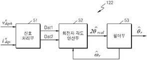
한편, 상기 회전자 위치 검출부는 신호 처리부, 회전자 각도 연산부, 및 필터부를 포함할 수 있다.Meanwhile, the rotor position detecting unit may include a signal processing unit, a rotor angle calculating unit, and a filter unit.
상기 신호 처리부는, 상기 제1 귀환전류 변환부로부터의 dS-축 및 qS-축 구동 전류들(iS dqs), 및 상기 주입 전압 발생부로부터의 dS-축 및 qS-축 주입 전압들(VS dqsh)을 입력받아, 현재 단위 주기에서의 qS-축 주입 전류의 값에서 이전 단위 주기에서의 dS-축 주입 전류의 값을 감산한 결과의 데이터(Dat1), 및 현재 단위 주기에서의 dS-축 주입 전류의 값에서 이전 단위 주기에서의 qS-축 주입 전류의 값을 가산한 결과의 데이터(Dat2)를 동시에 출력한다.The signal processor, d S from the first feedback current converter-axis and the q S-axis drive currents d S from the (i S dqs), and the injected voltage generation section-axis and the q S-axis injection It receives the voltages (V s dqsh), q s at the current unit of cycle-axis d s of the previous unit period from the value of the injected current-axis results of the data obtained by subtracting the value of the injection current (Dat1), and the current and it outputs the data (Dat2) the result of adding the value of the injected current at the same time shaft - q S in the previous unit period from the value of the axial injection current - d S in the unit period.
상기 회전자 각도 연산부는, 상기 신호 처리부로부터의 감산 결과의 데이터(Dat1) 및 가산 결과의 데이터(Dat2)를 상기 감산 방정식 및 가산 방정식에 각각 대입함에 의하여, 회전자 각도의 사인(sine) 성분 및 코사인(cosine) 성분을 구하고, 구해진 회전자 각도의 사인(sine) 성분 및 코사인(cosine) 성분에 따라 현재 단위 주기에서의 2 배의 회전자 각도(2![]()
![]()
상기 필터부는, 상기 회전자 각도 연산부로부터의 2 배의 회전자 각도(![]()
![]()
![]()
![]()
![]()
![]()
더 나아가, 상기 회전자 위치 검출부에 포함되어 있는 상기 신호 처리부는 제1 단위 주기 지연부, 극성 판별부, 대역 통과 필터, 제2 단위 주기 지연부, 제2 전류 감산부, 전류 가산부, 제1 곱셈부, 및 제2 곱셈부를 포함할 수 있다.Further, the signal processing unit included in the rotor position detection unit may include a first unit period delay unit, a polarity discriminator, a band pass filter, a second unit period delay unit, a second current subtractor, a current addition unit, A multiplier, and a second multiplier.
상기 제1 단위 주기 지연부는, 상기 주입 전압 발생부로부터의 dS-축 및 qS-축 주입 전압 값들(VS dqsh)을 한 단위 주기만큼 지연시켜서 출력함에 의하여, 현재 단위 주기에서의 dS-축 및 qS-축 주입 전압 값들(VS dqsh)을 발생시킨다.The first unit period delay unit from the injection voltage generating portion d S - axis and q S - axial injection voltage values (V S dqsh) to by as a unit by delayed cycle output, of d S in the current unit of cycle - axis and q S -axis generate the injection voltage values (V S dqsh ).
상기 극성 판별부는, 상기 제1 단위 주기 지연부로부터의 현재 단위 주기에서의 dS-축 및 qS-축 주입 전압 값들(VS dqsh)을 입력받아, 현재 단위 주기에서의 dS-축 주입 전압 값의 극성 신호(Sig D) 및 qS-축 주입 전압 값의 극성 신호(Sig Q)를 발생시킨다.The polarity discriminating unit, the first of d S in the current unit period from the sub-unit period delay-axis and the q S-axis injection voltage values (V S dqsh) the input received, d S at the current unit of cycle-axis injection The polarity signal Sig D of the voltage value and the polarity signal Sig Q of the q S -axis injection voltage value.
상기 대역 통과 필터는, 상기 제1 귀환전류 변환부로부터의 dS-축 및 qS-축 구동 전류들(iS dqs)에 대하여 대역 필터링을 수행함에 의하여, 현재 단위 주기에서의 dS-축 주입 전류의 값(iS dsh(j+1)) 및 qS-축 주입 전류의 값(iS qsh(j+1))을 발생시킨다.The band-pass filter, wherein the 1 d S from the negative feedback current conversion-axis and the q S-axis drive currents (i S dqs) of d S in the period the current unit by performing a band filtering on-axis It generates an-axis value of an injection current (i S qsh (j + 1 )) - the value of the injection current (i S dsh (j + 1 )) , and S q.
상기 제2 단위 주기 지연부는, 상기 대역 통과 필터로부터의 현재 단위 주기에서의 dS-축 주입 전류의 값(iS dsh(j+1)) 및 qS-축 주입 전류의 값(iS qsh(j+1))을 한 단위 주기만큼 지연시켜서 출력함에 의하여, 현재 단위 주기에서의 dS-축 주입 전류의 값(iS dsh(j+1)) 및 qS-축 주입 전류의 값(iS qsh(j+1))에 대한 이전 단위 주기에서의 dS-축 주입 전류의 값(iS dsh(j)) 및 qS-축 주입 전류의 값(iS qsh(j))을 발생시킨다.The second unit period delay unit, the bandpass d S of the current unit period from the filter - the value of the axial injection current (i S dsh (j + 1 )) and the q S-axis value of the injection current (i S qsh (j + 1)) a unit period by, d S of the current unit period by as by the output delay - the value of the axial injection current (i S dsh (j + 1)) and the q S-axis value of the injection current ( the axis value of the injection current (i S qsh (j)) - i S qsh (j + 1)) d S of the previous unit period for the - value of the axial injection current (i S dsh (j)) and a q S .
상기 제2 전류 감산부는, 상기 대역 통과 필터로부터의 현재 단위 주기에서의 qS-축 주입 전류의 값(iS qsh(j+1))에서 상기 제2 단위 주기 지연부로부터의 이전 단위 주기에서의 dS-축 주입 전류의 값(iS dsh(j))을 감산하고, 감산 결과의 값을 출력한다.Wherein the second current subtracting unit subtracts the value of the q S -axis injection current (i S qsh (j + 1)) in the current unit period from the band pass filter in the previous unit period from the second unit- of d S - subtracting the value of the axial injection current (i S dsh (j)), and outputs the value of the subtraction result.
상기 전류 가산부는, 상기 제2 단위 주기 지연부로부터의 이전 단위 주기에서의 qS-축 주입 전류의 값(iS qsh(j))과 상기 대역 통과 필터로부터의 현재 단위 주기에서의 dS-축 주입 전류의 값(iS dsh(j+1))을 가산하고, 가산 결과의 값을 출력한다.The current adding unit, wherein in a previous unit period from the sub-second unit period delay q S-axis value of the injection current (i S qsh (j)) and the d S in the current unit period from the bandpass filter - Adds the value of the axis injection current (i S dsh (j + 1)), and outputs the value of the addition result.
상기 제1 곱셈부는, 상기 제2 전류 감산부로부터의 감산 결과와 상기 극성 판별부로부터의 dS-축 주입 전압 값의 극성 신호(Sig D)를 입력받아, 상기 제2 전류 감산부로부터의 감산 결과에 dS-축 주입 전압 값의 극성을 곱하여 상기 감산 결과의 데이터(Dat1)를 발생시킨다.The first multiplication unit, and the second of d S from the subtraction result and the polarity determining unit from the current subtraction section-axis receives the injection voltage polarity signal (Sig D) of the second subtracted from the current subtraction unit the resulting S d - axis is multiplied by the polarity of the injection voltage and generates data (Dat1) of the subtraction result.
상기 제2 곱셈부는, 상기 전류 가산부로부터의 가산 결과와 상기 극성 판별부로부터의 qS-축 주입 전압 값의 극성 신호(Sig Q)를 입력받아, 상기 전류 가산부로부터의 가산 결과에 qS-축 주입 전압 값의 극성을 곱하여 상기 가산 결과의 데이터(Dat1)를 발생시킨다.Wherein the second multiplier receives the addition result from the current addition unit and the polarity signal (Sig Q) of the q S -axis injection voltage value from the polarity determination unit, and adds q S - The data (Dat1) of the addition result is generated by multiplying the polarity of the axial injection voltage value.
본 발명의 실시예에 의하면, 상기 제어 주입 주기에서, 극성 조합이 서로 다른 4 쌍의 dS-축 및 qS-축 주입 전압들이 순차적으로 인가된다. According to an embodiment of the present invention, the control in the injection cycle, the polarity combination with each other pair of the other 4 S d - S-axis and the q - axis injection voltage are applied sequentially.
또한, 상기 제어 주입 주기에서, 현재 단위 주기의 qS-축 주입 전류의 값에서 이전 단위 주기의 dS-축 주입 전류의 값이 감산된 결과, 및 현재 단위 주기의 dS-축 주입 전류의 값과 이전 단위 주기에서의 qS-축 주입 전류의 값이 가산된 결과에 따라, 현재 단위 주기에서의 회전자 각도가 구해질 수 있다.Further, in the control injection cycle, q S of the current unit of cycle-previous unit period in the axis value of the injection current d S - the value of the axial injection current subtraction result, and the present unit period d S - the axial injection current And the value of q S - axis injection current in the previous unit period are added, the rotor angle in the current unit period can be obtained.
즉, 교류 전동기의 인덕턴스에 의한 전압과 전류의 관계식들에 상기 감산 결과 및 상기 가산 결과를 대입하여, 현재 단위 주기에서의 회전자 각도가 구해질 수 있다. That is, the rotor angle in the current unit cycle can be obtained by substituting the subtraction result and the addition result into the relational expression of the voltage and current by the inductance of the AC motor.
그러므로, 레졸버와 같은 추가적인 회전자-위치 감지 장치를 사용하지 않고 내부적으로 회전자 위치를 검출할 수 있음에 따라, 교류 전동기의 구동 장치의 규모 및 제조 단가가 줄어들 수 있다.Therefore, since the rotor position can be internally detected without using an additional rotor-position sensing device such as a resolver, the size and manufacturing cost of the drive device of the AC motor can be reduced.
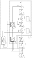
도 1은 본 발명의 일 실시예에 의한 교류 전동기의 구동 방법 및 장치를 설명하기 위한 블록도이다.
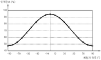
도 2는, 도 1의 실시예를 도출하는 원리로서, 일반적인 유도 전동기 내에서 회전자 각도에 따라 인덕턴스(inductance)가 변함을 보여주는 그래프이다.
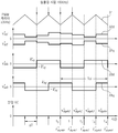
도 3은 도 1의 교류 전동기의 구동 장치에서 펄스폭 변조(PWM) 캐리어 신호의 제어 주기에 따른 제어 전압 변환부로부터의 dS-축 제어 전압 값(VS dsf), qS-축 제어 전압 값(VS qsf), 그리고 주입 전압 발생부로부터의 추가적인 dS-축 주입 전압 값(VS dsh) 및 qS-축 주입 전압 값(VS qsh)을 보여주는 타이밍도이다.
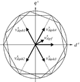
도 4는 제어 주입 주기에서 도 3의 dS-축과 qS-축 제어 전압 값들(VS dqsf)에 대하여 제1 dS-축과 qS-축 주입 전압들(VS dqsh1), 제2 dS-축과 qS-축 주입 전압들(VS dqsh2), 제3 dS-축과 qS-축 주입 전압들(VS dqsh3), 및 제4 dS-축과 qS-축 주입 전압들(VS dqsh4)이 단위 주기 별로 발생됨을 보여주는 벡터 도면이다.
도 5는 도 1의 회전자 위치 검출부의 내부 구성을 보여주는 블록도이다.
도 6은 도 5의 신호 처리부의 내부 구성을 보여주는 블록도이다.1 is a block diagram illustrating a method and apparatus for driving an alternating-current motor according to an embodiment of the present invention.
FIG. 2 is a graph showing the inductance of the induction motor according to the rotor angle, which is a principle for deriving the embodiment of FIG.
Axis control voltage value (V S dsf), q S - - 3 is d S from the control voltage converting unit in accordance with the control cycle of the pulse width modulation (PWM) carrier signal in the driving apparatus of the alternating current motor of Figure 1. Figure axis control voltage value (V S qsf), and further d S from the injection voltage generating unit - is a timing chart showing the injection axis voltage value (V S qsh) - injection axis voltage value (V S dsh) and S q.
4 is a control in Fig. 3 in the injection period d S - axis and the q S - - No. 1 d S with respect to the axis control voltage values (V S dqsf) - axis and the q S the axial injection voltage (V S dqsh1), the 2 d s - axis and the q s - axial injection voltages (V s dqsh2), the 3 d s - axis and the q s - axial injection voltages (V s dqsh3), and a 4 d s - axis and the q s - Is a vector diagram showing that the axial injection voltages (V s dqsh4 ) are generated per unit period.
5 is a block diagram showing the internal configuration of the rotor position detection unit of FIG.
6 is a block diagram showing an internal configuration of the signal processing unit of FIG.
하기의 설명 및 첨부된 도면은 본 발명에 따른 동작을 이해하기 위한 것이며, 본 기술 분야의 통상의 기술자가 용이하게 구현할 수 있는 부분은 생략될 수 있다. The following description and accompanying drawings are for understanding the operation according to the present invention, and parts that can be easily implemented by those skilled in the art can be omitted.
또한 본 명세서 및 도면은 본 발명을 제한하기 위한 목적으로 제공된 것은 아니고, 본 발명의 범위는 청구의 범위에 의하여 정해져야 한다. 본 명세서에서 사용된 용어들은 본 발명을 가장 적절하게 표현할 수 있도록 본 발명의 기술적 사상에 부합하는 의미와 개념으로 해석되어야 한다. Furthermore, the specification and drawings are not intended to limit the present invention, and the scope of the present invention should be determined by the claims. The terms used in the present specification should be construed to mean the meanings and concepts consistent with the technical idea of the present invention in order to best express the present invention.
참고로, 본 명세서, 도면 및 청구범위에서 위 첨자 s는 정지 좌표계를, 위 첨자 r은 동기 좌표계를, 그리고 아래 첨자 s는 고정자를 각각 가리킨다.For reference, in the present specification, drawings and claims, the superscript s denotes a stationary coordinate system, the superscript r denotes a synchronous coordinate system, and the subscript s denotes a stator.
이하, 첨부된 도면을 참조하여 본 발명의 실시예가 설명된다. Hereinafter, embodiments of the present invention will be described with reference to the accompanying drawings.
도 1은 본 발명의 일 실시예에 의한 교류 전동기의 구동 방법 및 장치를 설명하기 위한 블록도이다.1 is a block diagram illustrating a method and apparatus for driving an alternating-current motor according to an embodiment of the present invention.
도 2는, 도 1의 실시예를 도출하는 원리로서, 일반적인 유도 전동기 내에서 회전자 각도에 따라 인덕턴스(inductance)가 변함을 보여주는 그래프이다.FIG. 2 is a graph showing the inductance of the induction motor according to the rotor angle, which is a principle for deriving the embodiment of FIG.
도 3은 도 1의 교류 전동기의 구동 장치에서 펄스폭 변조(PWM) 캐리어 신호의 제어 주기에 따른 제어 전압 변환부로부터의 dS-축 제어 전압 값(VS dsf), qS-축 제어 전압 값(VS qsf), 그리고 주입 전압 발생부로부터의 추가적인 dS-축 주입 전압 값(VS dsh) 및 qS-축 주입 전압 값(VS qsh)을 보여주는 타이밍도이다.Axis control voltage value (V S dsf), q S - - 3 is d S from the control voltage converting unit in accordance with the control cycle of the pulse width modulation (PWM) carrier signal in the driving apparatus of the alternating current motor of Figure 1. Figure axis control voltage value (V S qsf), and further d S from the injection voltage generating unit - is a timing chart showing the injection axis voltage value (V S qsh) - injection axis voltage value (V S dsh) and S q.
도 4는, 제어 주입 주기에서 도 3의 dS-축과 qS-축 제어 전압 값들(VS dqsf)에 대하여 제1 dS-축과 qS-축 주입 전압들(VS dqsh1), 제2 dS-축과 qS-축 주입 전압들(VS dqsh2), 제3 dS-축과 qS-축 주입 전압들(VS dqsh3), 및 제4 dS-축과 qS-축 주입 전압들(VS dqsh4)이 단위 주기 별로 발생됨을 보여주는 벡터 도면이다.4 is a control injection of Figure 3 in the period d S - axis and the q S - - axial injection voltages (V S dqsh1), claim 1 d S with respect to the axis control voltage values (V S dqsf) - axis and the q S claim 2 d s - axis and the q s - axial injection voltages (V s dqsh2), the 3 d s - axis and the q s - the axial injection voltage (V s dqsh3), and a 4 d s - axis and the q s - It is a vector diagram showing that the axial injection voltages (V s dqsh4 ) are generated per unit period.
도 1 내지 4를 참조하면, 본 발명의 일 실시예의 구동 장치는 교류 전동기(11) 예를 들어, 영구자석 매입형 동기전동기(IPMSM : Interior-mounted Permanent Magnet Synchronous Motor)의 회전자 각도를 주기적으로 구하면서 교류 전동기(11)를 구동하는 것으로서, 제어부(12) 및 구동부(13)를 포함한다.Referring to FIGS. 1 to 4, a driving apparatus according to an embodiment of the present invention includes an
구동부(13)는 제어부(12)로부터의 인가 전압(VS dqs)에 따라 교류 전동기(11)를 구동한다.The driving
제어부(12)는 구동 제어부(121) 및 회전자 위치 검출부(122)를 포함한다.The
구동 제어부(121)는, 정지 좌표계에서의 여자 전류용 전압인 dS-축 전압과 정지 좌표계에서의 회전력 발생용 전압인 qS-축 전압(VS dqs)을 구동부(13)에 인가하되, 제어 주입 주기(도 3의 Tci)에서 극성 조합이 서로 다른 4 쌍의 dS-축 및 qS-축 주입 전압들(VS dqsh)을 순차적으로 인가한다.But applying an axial voltage (V S dqs) to the drive (13), - the
회전자 위치 검출부(122)는, 제어 주입 주기(Tci)에서, 현재 단위 주기(△T)의 qS-축 주입 전류의 값(iS qsh)에서 이전 단위 주기의 dS-축 주입 전류의 값(iS dsh)을 감산한 결과, 및 현재 단위 주기의 dS-축 주입 전류의 값(iS dsh)과 이전 단위 주기에서의 qS-축 주입 전류의 값(iS qsh)을 가산한 결과에 따라, 현재 단위 주기(△T)에서의 회전자 각도(![]()
![]()
즉, 교류 전동기(11)의 인덕턴스에 의한 전압과 전류의 관계식들에 상기 감산 결과 및 상기 가산 결과를 대입하여, 현재 단위 주기(△T)에서의 회전자 각도(![]()
![]()
따라서, 레졸버와 같은 추가적인 회전자-위치 감지 장치를 사용하지 않고 내부적으로 회전자 위치를 검출할 수 있음에 따라, 교류 전동기(11)의 구동 장치(12 및 13)의 규모 및 제조 단가가 줄어들 수 있다.Accordingly, since the rotor position can be internally detected without using an additional rotor-position sensing device such as a resolver, the size and manufacturing cost of the
교류 전동기(11)의 고정자에 3상 교류 전압이 인가됨에 의하여 교류 전동기(11)의 회전자가 회전한다. 여기에서, 구동부(13)는 구동 전압 변환부(131) 및 펄스 폭 변조부(132, PWM : Pulse Width Modulator)를 포함한다. When the three-phase AC voltage is applied to the stator of the AC
구동 전압 변환부(131)는 제어부(12)로부터의 dS-축 전압(VS ds)과 qS-축 전압(VS qs)인 상기 인가 전압들(VS dqs)을 3상 교류 전압으로 변환시킨다.The driving
펄스 폭 변조부(132)는 구동 전압 변환부(131)로부터의 3상 교류 전압을 펄스 폭 변조에 의하여 교류 전동기(11)의 고정자에 인가한다.The pulse width modulating unit 132 applies the three-phase alternating voltage from the driving
구동 제어부(12)는 제1 귀환전류 변환부(1211), 제2 귀환전류 변환부(1212), 제1 전류 감산부(1213), 비례-적분 제어부(1214), 순방향제어 전압 발생부(1215), 제1 전압 가산부(1216), 제어 전압 변환부(1217), 주입 전압 발생부(1218), 및 제2 전압 가산부(1219)를 포함한다.The driving
제1 귀환전류 변환부(1211)는 교류 전동기(11)의 고정자에 흐르는 3상 좌표계(abcs)에서의 3상 구동 전류를 검출하여 상기 정지 좌표계(dqs)에서의 dS-축 및 qS-축 구동 전류 값들(iS dqs)을 구한다.The first of d S in the feedback
제2 귀환전류 변환부(1212)는, 회전자 위치 검출부(122)가 알려주는 회전자 각도(![]()
![]()
제1 전류 감산부(1213)는 동기 좌표계(dqr)에서의 dS-축 및 qS-축 목표 전류 값들(ir * dqs)과 제2 귀환전류 변환부(1212)로부터의 dS-축 및 qS-축 구동 전류 값들(ir dqs)의 차이 값들인 오차 전류 값들을 발생시킨다.Claim of d S in the first
비례-적분 제어부(1214)는 제1 감산부(1213)로부터의 오차 전류 값들에 비례-적분 제어를 수행하여 동기 좌표계(dqr)에서의 dS-축 및 qS-축 귀환제어 전압 값들(Vr dqsfb)을 구한다.The proportional-
순방향제어 전압 발생부(1215)는 교류 전동기(11)의 고유 특성에 부합되는 동기 좌표계(dqr)에서의 dS-축 및 qS-축 순방향제어 전압 값들(Vr dqsff)을 발생시킨다.Forward control voltage generation section 1215 S d in synchronization with the coordinate system (dqr) consistent with the intrinsic properties of the alternating current motor (11) generates an axial forward control voltage values (V r dqsff) - S-axis and q.
제1 전압 가산부(1216)는 비례-적분 제어부(1214)로부터의 dS-축 및 qS-축 귀환제어 전압 값들(Vr dqsfb) 및 순방향제어 전압 발생부(1215)로부터의 dS-축 및 qS-축 순방향제어 전압 값들(Vr dqsff)이 더해진 결과의 dS-축 및 qS-축 제어 전압 값들(Vr dqsf)을 발생시킨다.A first
제어 전압 변환부(1217)는, 입력되는 회전자 각도(![]()
![]()
회전자 위치 검출을 위한 주입 전압 발생부(1218)는 제어 주입 주기(도 3의 Tci)에서 극성 조합이 서로 다른 4 쌍의 상기 dS-축 및 qS-축 주입 전압들(VS dqsh)을 순차적으로 발생시킨다.The axial injection voltage (V S dqsh) - injections voltage for electronic position
여기에서, 제어 주입 주기(도 3의 Tci)의 역수인 제어 주입 주파수는 펄스 폭 변조부(132)의 스위칭 주파수의 1/2이다. Here, the control injection frequency, which is an inverse number of the control injection period (Tci in Fig. 3), is 1/2 of the switching frequency of the pulse width modulation unit 132. [
예를 들어, 펄스 폭 변조부(132)의 스위칭 주파수가 5 킬로-헤르쯔(KHz)이고, 비례-적분 제어부(1214)가 이중 샘플링을 수행할 경우, 비례-적분 제어부(1214)의 샘플링 주파수는 10 킬로-헤르쯔(KHz)이며, 제어 주입 주파수는 2.5 킬로-헤르쯔(KHz)이다(도 3 및 4 참조).For example, when the switching frequency of the pulse width modulation section 132 is 5 kilohertz (KHz) and the proportional-
이와 같이 상대적으로 낮은 제어 주입 주파수가 사용됨에 따라 비례-적분 제어부(1214)의 응답 성능이 더욱 향상될 수 있는 추가적 효과가 있다.As such a relatively low control injection frequency is used, there is a further effect that the response performance of the proportional-
제2 전압 가산부(1219)는 제어 전압 변환부(1217)로부터의 정지 좌표계(dqs)에서의 dS-축 및 qS-축 제어 전압 값들(VS dqsf) 및 주입 전압 발생부(1215)로부터의 정지 좌표계(dqs)에서의 dS-축 및 qS-축 주입 전압 값들(VS dqsh)이 가산된 결과의 상기 인가 전압들(VS dqs)을 구동부(13) 내의 구동 전압 변환부(131)에 입력시킨다.Second voltage addition unit 1219 d S in the still coordinate system (dqs) from the control voltage converting unit 1217-axis and the q S-axis control voltage values (V S dqsf) and injection
제어 주입 주기(도 3의 Tci)에 있어서, 제1 단위 주기(도 3의 샘플링 주기 △T, t0 내지 t1)에서 제1 dS-축 및 qS-축 주입 전압(VS dqsh1)이 인가되고, 제2 단위 주기(t1 내지 t2)에서 제2 dS-축 및 qS-축 주입 전압(VS dqsh2)이 인가되고, 제3 단위 주기(t2 내지 t3)에서 제3 dS-축 및 qS-축 주입 전압(VS dqsh3)이 인가되고, 제4 단위 주기(t3 내지 t4)에서 제4 dS-축 및 qS-축 주입 전압(VS dqsh4)이 인가된다.Axis and the q S - - axial injection voltage (V S dqsh1) in the control injection period (Tci in Fig. 3), the first 1 d S in one unit period (sampling period of 3 △ T, t 0 to t 1) is applied and the second unit period (t 1 to t 2) the second d S in the - in the axial injection voltage (V S dqsh2) is applied, the third unit period (t 2 to t 3)-axis and q S claim 3 d S - axis and q S - axial injection a voltage (V S dqsh3) is applied, a fourth a fourth unit period (t 3 to t 4) d S - axis and q S - axial injection voltage (V S dqsh4 ) is applied.
이하, 도 1의 회전자 위치 검출부(122)의 동작 원리가 수학식들과 함께 설명된다.Hereinafter, the operation principle of the rotor
일반적으로, 3상 교류 전동기(11)의 정지 좌표계의 전압 방정식들은 아래의 수학식 1과 같이 표현된다. Generally, the voltage equations of the stationary coordinate system of the three-phase AC

위 수학식 1에서 vS ds는 dS-축 제어 전압 값을, vS qs는 qS-축 제어 전압 값을, RS는 고정자 저항값을, iS ds는 dS-축 고정자 전류 값을, iS qs는 qS-축 고정자 전류 값을, λS ds는 dS-축 자속 값을, λS qs는 qS-축 자속 값을, LS는 인덕턴스 매트릭스를, λf는 기본 자속 값을, θr은 회전자 각도를, Lds는 dS-축 인덕턴스 값을, 그리고 Lqs는 qS-축 인덕턴스 값을 각각 가리킨다.In the above Equation 1 v S ds is d S - the axis control voltage values, v S qs is q S - to the axis control voltage value, R S is the stator resistance, i S ds is d S - axis stator current a, i S qs is q S - axis stator current value, λ S ds is d S - an axial magnetic flux value, λ S qs is q S - an axial magnetic flux value, L S is the inductance matrix, λ f is a primary a magnetic flux value, θ r is e times the angle, L ds is d S - axis inductance, and L is qs q S - refers to the axis inductance, respectively.
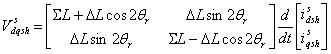
따라서, 인덕턴스에 의한 전압과 전류의 관계식은 아래의 수학식 2와 같이 유도될 수 있다. Therefore, a relational expression of voltage and current due to inductance can be derived as shown in Equation (2) below.

위 수학식 2에서, ωr은 회전자 각속도를, vS dqs는 dS-축 또는 qS-축 제어 전압 값을, iS dqs는 dS-축 또는 qS-축 전류 값을, iS ds는 dS-축 전류 값을, iS qs는 qS-축 전류 값을 각각 가리킨다.In the above equation (2), ω r denotes a rotor angular velocity, v S dqs denotes a d S -axis or q S -axis control voltage value, i S dqs denotes a d S -axis or q S- S ds is d S - a-axis current value, S i is qs q S - refers to a-axis current value, respectively.
여기에서, 주입 전압 발생부(1215)로부터의 정지 좌표계(dqs)에서의 dS-축 및 qS-축 주입 전압들(VS dqsh)의 주파수는 제어 전압 변환부(1217)로부터의 정지 좌표계(dqs)에서의 dS-축 및 qS-축 제어 전압들(VS dqsf)의 주파수에 비하여 상당히 높다. Here, the d S in the still coordinate system (dqs) from the injection voltage generation unit 1215-axis and the q S-axis injection voltage frequency of (V S dqsh) is still coordinate system from the control
즉, 위 수학식 2의 우변에서 두번째 항을 제외한 모든 항들을 삭제하면, 정지 좌표계(dqs)에서의 dS-축 또는 qS-축의 주입 전압의 값(VS dqsh) 및 주입 전류 값(iS dqsh)의 관계식이 된다. 따라서, 이 관계식에 상기 수학식 1의 인덕턴스 매트릭스를(LS)를 대입하면 아래의 수학식 3을 도출할 수 있다.That is, in the above to remove all anti except for the second term on the right hand side of equation (2), rotating coordinates (dqs) d S - axis or q S - axis value of the injected voltage (V S dqsh) and the injection current value (i S dqsh ). Therefore, by substituting (L S ) for the inductance matrix of the above equation (1) into this relation, the following equation (3) can be derived.
또한, 위 수학식 3을 주입 전류 값(iS dqsh)에 대하여 정리하면, 아래의 수학식 4가 성립된다.When the above formula (3) is summarized with respect to the injection current value (i S dqsh ), the following equation (4) is established.

한편, 본 실시예의 경우, dS-축 주입 전압(VS dsh)이 시간(t)에 대하여 사인(sine) 함수이면 qS-축의 주입 전압(VS qsh)은 시간(t)에 대하여 코사인(sine) 함수이다. 즉, 주입 전압 발생부(1215)로부터의 정지 좌표계(dqs)에서의 dS-축 및 qS-축 주입 전압 값들(VS dqsh)은 아래의 수학식 5에 의하여 구해질 수 있다(도 3 및 4 참조).On the other hand, in the case of this embodiment, d S - axial injection voltage (V S dsh) q S sine (sine) functions is with respect to the time (t) - the axis injection voltage (V S qsh) is a cosine with respect to time (t) (sine) function. That is, the injection voltage generation unit of d S in the still coordinate system (dqs) from a 1215-can the be obtained by the equation (5) under axial injection voltage values (V S dqsh) (3-axis and the q S And 4).

상기 수학식 5에서 Vinj는 dS-축 또는 qS-축의 주입 전압(VS dqsh)의 크기이고, ωh는 주입 전압(VS dqsh)의 각속도이다.In Equation 5 V inj is S d - axis or q S - is the size of the injection axis voltage (V S dqsh), ω h is an angular velocity of the injected voltage (V S dqsh).
여기에서, 상기 수학식 5를 상기 수학식 4에 대입하면, 2 배의 회전자 각도(cos 2θr)의 코사인 성분(cos 2θr)으로부터 dS-축 주입 전류(iS dsh)를 구할 수 있고, 2 배의 회전자 각도(cos 2θr)의 사인 성분(sin 2θr)으로부터 qS-축 주입 전류(iS qsh)를 구할 수 있다. 즉, 아래의 수학식 6이 도출될 수 있다.In this case, Substituting Equation (5) to Equation (4), the rotor angle cosine component of (cos 2θ r) of twice (cos 2θ r) from the d S - axis to obtain the injection current (i S dsh) , And the q S -axis injection current (i S qsh ) can be obtained from the sinusoidal component (sin 2θ r ) of the rotor angle (cos 2θ r ) at two times. That is, the following equation (6) can be derived.

여기에서, 제어 주입 주기(도 3의 Tci)는 제1 단위 주기(도 3의 t0 내지 t1), 제2 단위 주기(t1 내지 t2), 제3 단위 주기(t2 내지 t3), 및 제4 단위 주기(t3 내지 t4)로 구분된다. 제1 단위 주기(도 3의 t0 내지 t1)에서의 전압 주입 시점은 t0이고, 제2 단위 주기(t1 내지 t2)에서의 전압 주입 시점은 t1이며, 제3 단위 주기(t2 내지 t3)에서의 전압 주입 시점은 t2이고, 제4 단위 주기(t3 내지 t4)에서의 전압 주입 시점은 t3이다.Here, the controlled injection period (Tci in Fig. 3) includes a first unit period (Fig. 3 of t 0 to t 1), the second unit period (t 1 to t 2), the third unit period (t 2 to t 3 ), And a fourth unit period (t 3 to t 4 ). The voltage injection point in the first unit period (t 0 to t 1 in FIG. 3) is t 0 , the voltage injection point in the second unit period (t 1 to t 2 ) is t 1 , and the third unit period t 2 to t 3 is t 2, and the voltage injection time at the fourth unit period (t 3 to t 4 ) is t 3 .
따라서, 상기 수학식 6에 있어서, 주입 전압(VS dqsh)의 각속도(ωh)와 시간(t)을 곱한 결과(ωht)가 영(0)인 때가 제1 단위 주기(도 3의 t0 내지 t1)에 해당된다. 또한, 주입 전압(VS dqsh)의 각속도(ωh)와 시간(t)을 곱한 결과(ωht)가 π/2인 때가 제2 단위 주기(도 3의 t1 내지 t2)에 해당된다. 또한, 주입 전압(VS dqsh)의 각속도(ωh)와 시간(t)을 곱한 결과(ωht)가 π인 때가 제3 단위 주기(도 3의 t2 내지 t3)에 해당된다. 그리고, 주입 전압(VS dqsh)의 각속도(ωh)와 시간(t)을 곱한 결과(ωht)가 3π/2인 때가 제4 단위 주기(도 3의 t3 내지 t4)에 해당된다. Therefore, when the result (ω h t) obtained by multiplying the angular speed (ω h ) of the injection voltage (V s dqsh ) by the time t is 0 in the above Equation (6) t 0 to t 1 ). When the result (ω h t) obtained by multiplying the angular speed ω h of the injection voltage (V s dqsh ) by the time t is π / 2 corresponds to the second unit period (t 1 to t 2 in FIG. 3) do. When the result (ω h t) obtained by multiplying the angular velocity ω h of the injection voltage (V s dqsh ) by the time t corresponds to the third unit period (t 2 to t 3 in FIG. 3 ). Then, when the result (ω h t) of the angular velocity ω h of the injection voltage (V s dqsh ) multiplied by the time t is 3π / 2 corresponds to the fourth unit period (t 3 to t 4 in FIG. 3) do.
따라서, 상기 내용을 상기 수학식 6에 대입함에 의하여, 각각의 단위 주기에서의 dS-축 주입 전류(iS dsh)와 qS-축 주입 전류(iS qsh)를 계산하는 식들을 도출할 수 있다.Thus, by as substituted for the details on the equation 6, d S in each unit period of the - to derive the formula to calculate the axial injection current (i S qsh)-axis injection current (i S dsh) and q S .
따라서, 제1 단위 주기(도 3의 t0 내지 t1)에서의 dS-축 주입 전류(iS dsh1)와 qS-축 주입 전류(iS qsh1)를 계산하는 식은 아래의 수학식 7과 같이 표현될 수 있다.Thus, the first unit period (Fig. 3 of t 0 to t 1) of d S in-axis injection current (i S dsh1) and q S-axis injection current (i S qsh1) equation of equations below for calculating a 7 Can be expressed as:

또한, 제2 단위 주기(도 3의 t1 내지 t2)에서의 dS-축 주입 전류(iS dsh2)와 qS-축 주입 전류(iS qsh2)를 계산하는 식은 아래의 수학식 8과 같이 표현될 수 있다.In addition, the second unit period (Fig. 3 of t 1 to t 2) of d S in-axis injection current (i S dsh2) and q S-axis equation Equation 8 below for calculating the injection current (i S qsh2) Can be expressed as:

또한, 제3 단위 주기(도 3의 t2 내지 t3)에서의 dS-축 주입 전류(iS dsh3)와 qS-축 주입 전류(iS qsh3)를 계산하는 식은 아래의 수학식 9와 같이 표현될 수 있다.In addition, the third unit period (Fig. 3 of t 2 to t 3) of d S in-axis injection current (i S dsh3) and q S-axis expression equation below 9 for calculating the injection current (i S qsh3) Can be expressed as

그리고, 제4 단위 주기(도 3의 t3 내지 t4)에서의 dS-축 주입 전류(iS dsh4)와 qS-축 주입 전류(iS qsh4)를 계산하는 식은 아래의 수학식 10과 같이 표현될 수 있다.And a fourth unit period (Fig. 3 of t 3 to t 4) of d S in-axis injection current (i S dsh4) and q S-axis expression equation (10) below to calculate the injection current (i S qsh4) Can be expressed as:

상기 수학식 7 내지 10을 이용하면, 이전 단위 주기와 현재 단위 주기 사이에서 감산 방정식 및 가산 방정식이 공통적으로 설정될 수 있다. 또한, 측정된 주입 전류의 값들을 상기 감산 방정식 및 가산 방정식에 대입함에 의하여, 2 배의 회전자 각도(2θr)의 코사인 성분(cos 2θr) 및 사인 성분(sin 2θr)이 구해질 수 있고, 구해진 코사인 성분(cos 2θr) 및 사인 성분(sin 2θr)으로부터 현재 단위 주기에서의 회전자 각도(θr)가 구해질 수 있다.Using Equations (7) to (10), subtraction equations and addition equations can be commonly set between the previous unit period and the current unit period. Further, a cosine component of the rotor angle (2θ r) of 2 times by as substituting the value of the measured injection current to the subtraction equations and adding equation (cos 2θ r) and sine component (sin 2θ r) can be obtained and, a cosine component (cos 2θ r) and sine component (sin 2θ r) from the rotor angle (θ r) of the current unit period is determined may be obtained.
이전 단위 주기와 현재 단위 주기 사이에서 감산 방정식 및 가산 방정식은 아래의 수학식 11과 같이 설정될 수 있다.Between the previous unit cycle and the current unit cycle, the subtraction equation and the addition equation can be set as shown in Equation (11) below.

상기 수학식 11을 요약하면, 각각의 단위 주기에서, 2 배의 회전자 각도(2θr)의 코사인 성분(cos 2θr) 및 사인 성분(sin 2θr)을 계산하기 위하여, 다음의 두 가지 연산들이 먼저 수행된다. To summarize the equation (11), to calculate for each of the unit cycle, times the cosine component of the electronic angle (2θ r) of twice (cos 2θ r) and sine component (sin 2θ r), the following two operations Are performed first.
첫째, 현재 단위 주기에서의 qS-축 주입 전류의 값(iS qsh(j+1))에서 이전 단위 주기에서의 dS-축 주입 전류의 값(iS dsh(j))이 감산되고, 감산 결과에 dS-축 주입 전압 값의 극성(+ 또는 -)이 곱해져서 감산 결과의 데이터(Dat1)가 발생된다.First, q S at the current unit of cycle-axis value of the injection current (i S qsh (j + 1 )) at d S in the previous unit period - the value of the axial injection current (i S dsh (j)) is subtracted , the subtraction result S d-axis injection polarity (+ or -) of the voltage value of the subtraction result data (Dat1) haejyeoseo the product is generated.
둘째, 이전 단위 주기에서의 qS-축 주입 전류의 값(iS qsh(j))과 현재 단위 주기에서의 dS-축 주입 전류의 값(iS dsh(j+1))을 가산하고, 가산 결과에 qS-축 주입 전압 값의 극성(+ 또는 -)이 곱해져서 가산 결과의 데이터(Dat2)가 발생된다Second, q S in the previous unit period - and adding the value of the axial injection current (i S dsh (j + 1 )) - axis value of the injection current (i S qsh (j)) and d S of the current unit period , The addition result is multiplied by the polarity (+ or -) of the q S -axis injection voltage value, and the addition result data Dat2 is generated
상기 4 단위 주기들에 있어서, dS-축 주입 전압 값의 극성 sign(VS dsh), qS-축 주입 전압 값의 극성 sign(VS qsh), 사인 성분(sin 2θr)의 연산식들, 및 코사인 성분(cos 2θr)의 연산식들을 순서대로 요약하면 아래의 표 1과 같다.The polarity sign (V S dsh ) of the d S -axis injection voltage value, the polarity sign (V S qsh ) of the q S -axis injection voltage value, and the sine component (sin 2? R ) And cosine components (cos 2? R ) are summarized in the following Table 1.
따라서, 각각의 단위 주기에 있어서, 2 배의 회전자 각도(2θr)의 코사인 성분(cos 2θr) 및 사인 성분(sin 2θr)이 구해지고, 아크 탄젠트(tan-1) 연산에 의하여 현재 단위 주기에서의 회전자 각도(θr)가 구해질 수 있다.Thus, the current in each of the unit cycle, the double rotor angle cosine component of the (2θ r) (cos 2θ r ) and sine component (sin 2θ r) is obtained, by the arc tangent (tan -1) operation The rotor angle? R in the unit period can be obtained.
그러므로, 레졸버와 같은 추가적인 회전자-위치 감지 장치를 사용하지 않고 내부적으로 회전자 위치를 검출할 수 있음에 따라, 교류 전동기의 구동 장치의 규모 및 제조 단가가 줄어들 수 있다.Therefore, since the rotor position can be internally detected without using an additional rotor-position sensing device such as a resolver, the size and manufacturing cost of the drive device of the AC motor can be reduced.
도 5는 도 1의 회전자 위치 검출부(122)의 내부 구성을 보여준다.5 shows the internal structure of the
도 1 및 5를 참조하면, 회전자 위치 검출부(122)는 신호 처리부(51), 회전자 각도 연산부(52), 및 필터부(53)를 포함한다.1 and 5, the rotor
신호 처리부(51)는, 제1 귀환전류 변환부(1211)로부터의 dS-축 및 qS-축 구동 전류들(iS dqs), 및 주입 전압 발생부(1218)로부터의 dS-축 및 qS-축 주입 전압들(VS dqsh)을 입력받아, 현재 단위 주기에서의 qS-축 주입 전류의 값에서 이전 단위 주기에서의 dS-축 주입 전류의 값을 감산한 결과의 데이터(Dat1), 및 현재 단위 주기에서의 dS-축 주입 전류의 값에서 이전 단위 주기에서의 qS-축 주입 전류의 값을 가산한 결과의 데이터(Dat2)를 동시에 출력한다.
회전자 각도 연산부(52)는, 신호 처리부(51)로부터의 감산 결과의 데이터(Dat1) 및 가산 결과의 데이터(Dat2)를 상기 수학식 11의 감산 및 가산 방정식에 각각 대입함에 의하여, 회전자 각도의 사인(sine) 성분 및 코사인(cosine) 성분을 구하고, 구해진 회전자 각도의 사인(sine) 성분(sin 2θr) 및 코사인(cosine) 성분(cos 2θr)에 따라 현재 단위 주기에서의 2 배의 회전자 각도(2![]()
![]()
필터부(53)는, 회전자 각도 연산부(52)로부터의 2 배의 회전자 각도(![]()
![]()
![]()
![]()
![]()
![]()
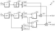
도 6은 도 5의 신호 처리부(51)의 내부 구성을 보여준다.Fig. 6 shows the internal configuration of the
도 1, 6 및 상기 표 1을 참조하면, 회전자 위치 검출부(122)에 포함되어 있는 신호 처리부(51)는 제1 단위 주기 지연부(601), 극성 판별부(602), 대역 통과 필터(603), 제2 단위 주기 지연부(604), 제2 전류 감산부(605), 전류 가산부(606), 제1 곱셈부(607), 및 제2 곱셈부(608)를 포함한다.1, 6 and Table 1, the
제1 단위 주기 지연부(601)는, 주입 전압 발생부(1218)로부터의 dS-축 및 qS-축 주입 전압 값들(VS dqsh)을 한 단위 주기만큼 지연시켜서 출력함에 의하여, 현재 단위 주기에서의 dS-축 및 qS-축 주입 전압 값들(VS dqsh)을 발생시킨다.A first unit
극성 판별부(602)는, 제1 단위 주기 지연부(601)로부터의 현재 단위 주기에서의 dS-축 및 qS-축 주입 전압 값들(VS dqsh)을 입력받아, 현재 단위 주기에서의 dS-축 주입 전압 값의 극성 신호(Sig D) 및 qS-축 주입 전압 값의 극성 신호(Sig Q)를 발생시킨다.
대역 통과 필터(603)는, 제1 귀환전류 변환부(1211)로부터의 dS-축 및 qS-축 구동 전류들(iS dqs)에 대하여 대역 필터링을 수행함에 의하여, 현재 단위 주기에서의 dS-축 주입 전류의 값(iS dsh(j+1)) 및 qS-축 주입 전류의 값(iS qsh(j+1))을 발생시킨다.A band-
제2 단위 주기 지연부(604)는, 대역 통과 필터(603)로부터의 현재 단위 주기에서의 dS-축 주입 전류의 값(iS dsh(j+1)) 및 qS-축 주입 전류의 값(iS qsh(j+1))을 한 단위 주기만큼 지연시켜서 출력함에 의하여, 현재 단위 주기에서의 dS-축 주입 전류의 값(iS dsh(j+1)) 및 qS-축 주입 전류의 값(iS qsh(j+1))에 대한 이전 단위 주기에서의 dS-축 주입 전류의 값(iS dsh(j)) 및 qS-축 주입 전류의 값(iS qsh(j))을 발생시킨다.A second unit
제2 전류 감산부(605)는, 대역 통과 필터(603)로부터의 현재 단위 주기에서의 qS-축 주입 전류의 값(iS qsh(j+1))에서 제2 단위 주기 지연부(604)로부터의 이전 단위 주기에서의 dS-축 주입 전류의 값(iS dsh(j))을 감산하고, 감산 결과의 값을 출력한다.The second
전류 가산부(606)는, 제2 단위 주기 지연부(604)로부터의 이전 단위 주기에서의 qS-축 주입 전류의 값(iS qsh(j))과 상기 대역 통과 필터로부터의 현재 단위 주기에서의 dS-축 주입 전류의 값(iS dsh(j+1))을 가산하고, 가산 결과의 값을 출력한다.The current adding
제1 곱셈부(607)는, 제2 전류 감산부(605)로부터의 감산 결과와 극성 판별부(602)로부터의 dS-축 주입 전압 값의 극성 신호(Sig D)를 입력받아, 제2 전류 감산부(605)로부터의 감산 결과에 dS-축 주입 전압 값의 극성을 곱하여 상기 감산 결과의 데이터(Dat1)를 발생시킨다.The
제2 곱셈부(608)는, 전류 가산부(606)로부터의 가산 결과와 극성 판별부(602)로부터의 qS-축 주입 전압 값의 극성 신호(Sig Q)를 입력받아, 전류 가산부(606)로부터의 가산 결과에 qS-축 주입 전압 값의 극성을 곱하여 상기 가산 결과의 데이터(Dat1)를 발생시킨다.The
이상 설명된 바와 같이, 본 발명의 실시예에 의하면, 제어 주입 주기에서, 극성 조합이 서로 다른 4 쌍의 dS-축 및 qS-축 주입 전압들이 순차적으로 인가된다. As described above, according to embodiments of the present invention, controlled by the injection period, the polarity of each other in combination with other four pairs of S d - S-axis and the q - axis injection voltage are applied sequentially.
또한, 제어 주입 주기에서, 현재 단위 주기의 qS-축 주입 전류의 값에서 이전 단위 주기의 dS-축 주입 전류의 값이 감산된 결과, 및 현재 단위 주기의 dS-축 주입 전류의 값과 이전 단위 주기에서의 qS-축 주입 전류의 값이 가산된 결과에 따라, 현재 단위 주기에서의 회전자 각도가 구해질 수 있다.Further, the control implant in the period, the current unit period q S-axis d S of the previous unit period from the value of the injection current - the value of the axial injection current subtraction result, and the present unit period d S-value in the axial injection current And the value of q S - axis injection current in the previous unit cycle are added, the rotor angle in the present unit cycle can be obtained.
즉, 교류 전동기의 인덕턴스에 의한 전압과 전류의 관계식들에 상기 감산 결과 및 상기 가산 결과를 대입하여, 현재 단위 주기에서의 회전자 각도가 구해질 수 있다. That is, the rotor angle in the current unit cycle can be obtained by substituting the subtraction result and the addition result into the relational expression of the voltage and current by the inductance of the AC motor.
그러므로, 레졸버와 같은 추가적인 회전자-위치 감지 장치를 사용하지 않고 내부적으로 회전자 위치를 검출할 수 있음에 따라, 교류 전동기의 구동 장치의 규모 및 제조 단가가 줄어들 수 있다.Therefore, since the rotor position can be internally detected without using an additional rotor-position sensing device such as a resolver, the size and manufacturing cost of the drive device of the AC motor can be reduced.
이제까지 본 발명에 대하여 바람직한 실시예를 중심으로 살펴보았다. 본 발명이 속하는 기술 분야에서 통상의 지식을 가진 자는 본 발명의 본질적인 특성에서 벗어나지 않는 범위에서 변형된 형태로 본 발명을 구현할 수 있음을 이해할 것이다. 그러므로 상기 개시된 실시예는 한정적인 관점이 아니라 설명적인 관점에서 고려되어야 한다. 본 발명의 범위는 전술한 설명이 아니라 특허청구범위에 나타나 있으며, 특허청구범위에 의해 청구된 발명 및 청구된 발명과 균등한 발명들은 본 발명에 포함된 것으로 해석되어야 한다.The present invention has been described above with reference to preferred embodiments. It will be understood by those skilled in the art that the present invention may be embodied in various other forms without departing from the spirit or essential characteristics thereof. Therefore, the above-described embodiments should be considered in a descriptive sense rather than a restrictive sense. The scope of the present invention is defined by the appended claims rather than by the foregoing description, and the inventions claimed by the claims and the inventions equivalent to the claimed invention are to be construed as being included in the present invention.
교류 전동기 외의 직류 전동기에서도 이용될 가능성이 있다.There is a possibility of being used in a DC motor other than an AC motor.
11: 교류 전동기, 12: 제어부,
13: 구동부, 121: 구동 제어부,
122: 회전자 위치 검출부, 131: 구동 전압 변환부
132: 펄스 폭 변조부, 1211: 제1 귀환전류 변환부,
1212: 제2 귀환전류 변환부, 1213: 제1 전류 감산부,
1214; 비례-적분 제어부, 1215: 순방향제어 전압 발생부,
1216: 제1 전압 가산부, 1217: 제어 전압 변환부,
1218: 주입 전압 발생부, 1219: 제2 전압 가산부,
51: 신호 처리부, 52: 회전자 각도 연산부,
53: 필터부, 601: 제1 단위 주기 지연부,
602: 극성 판별부, 603: 대역 통과 필터,
604: 제2 단위 주기 지연부, 605: 제2 전류 감산부,
606: 전류 가산부, 607: 제1 곱셈부,
608: 제2 곱셈부.11: AC motor, 12: control part,
13: driving unit, 121: driving control unit,
122: rotor position detection unit, 131: drive voltage conversion unit
132: pulse width modulation unit, 1211: first feedback current conversion unit,
1212: second feedback current conversion section, 1213: first current subtraction section,
1214; A proportional-integral control unit, 1215: a forward control voltage generating unit,
1216: first voltage adding unit, 1217: control voltage converting unit,
1218: an injection voltage generating unit, 1219: a second voltage adding unit,
51: signal processing section, 52: rotor angle calculating section,
53: filter unit, 601: first unit-cycle delay unit,
602: Polarity discrimination unit, 603: Band-pass filter,
604: second unit period delay unit, 605: second current subtractor,
606: current addition unit, 607: first multiplier unit,
608: second multiplication unit.
Claims (11)
(a) 정지 좌표계에서의 여자 전류용 전압인 dS-축 전압과 정지 좌표계에서의 회전력 발생용 전압인 qS-축 전압에 의하여 상기 교류 전동기를 구동하되, 제어 주입 주기에서 극성 조합이 서로 다른 4 쌍의 dS-축 및 qS-축 주입 전압들을 순차적으로 인가하는 단계;
(b) 상기 제어 주입 주기에서, 현재 단위 주기의 qS-축 주입 전류의 값에서 이전 단위 주기의 dS-축 주입 전류의 값을 감산한 결과, 및 현재 단위 주기의 dS-축 주입 전류의 값과 이전 단위 주기에서의 qS-축 주입 전류의 값을 가산한 결과에 따라, 현재 단위 주기에서의 회전자 각도를 구하는 단계를 포함하고,
상기 단계 (a) 및 상기 단계 (b)에서,
상기 제어 주입 주기가 4 등분됨에 의하여 4 단위 주기들이 설정되고,
상기 4 단위 주기들 각각에서의 qS-축 주입 전류와 dS-축 주입 전류는 상기 4 단위 주기들에서 4 쌍의 dS-축 및 qS-축 주입 전압들이 순차적으로 주입됨에 의하여 고정자에 추가적으로 흘려지는 전류들인, 교류 전동기의 구동 방법.A method of driving an alternating-current motor in which the alternating-current motor is driven while periodically determining a rotor angle of the alternating-current motor,
q S voltage for the rotational force generated in the axial voltage and the still coordinate system - - (a) rotating coordinates exciting current voltage of d S for in by the shaft voltage, but driving the alternating current motor, controlled injection cycle polarity combination is different from four pairs of S d - S-axis and the q - the method comprising applying axial injection voltage in sequence;
(b) in the control injection cycle, q S of the current unit of cycle - a result of subtracting the value of the axial injection current, and the current unit period d S - - d S of the previous unit period in the axis value of the injection current axial injection current the value of S and q in the previous unit period - according to the result of adding the value of the axial injection current, and a step to obtain a rotor angle in the current unit period,
In the step (a) and the step (b)
Four unit periods are set by dividing the control injection period by four,
To the stator, by As-axis injection voltage are injected sequentially-axis injection current and d S--axis injection current is four pairs of d S in the four-unit period-axis and the q S q S at each of the four unit periods And a current flowing in addition to the AC motor.
제어부; 및
상기 제어부로부터의 인가 전압에 따라 상기 교류 전동기를 구동하는 구동부를 포함하고,
상기 제어부가,
정지 좌표계에서의 여자 전류용 전압인 dS-축 전압과 정지 좌표계에서의 회전력 발생용 전압인 qS-축 전압에 의하여 상기 교류 전동기를 구동하되, 제어 주입 주기에서 극성 조합이 서로 다른 4 쌍의 dS-축 및 qS-축 주입 전압들을 순차적으로 인가하는 구동 제어부; 및
상기 제어 주입 주기에서, 현재 단위 주기의 qS-축 주입 전류의 값에서 이전 단위 주기의 dS-축 주입 전류의 값을 감산한 결과, 및 현재 단위 주기의 dS-축 주입 전류의 값과 이전 단위 주기에서의 qS-축 주입 전류의 값을 가산한 결과에 따라, 현재 단위 주기에서의 회전자 각도를 구하는 회전자 위치 검출부를 포함하며,
상기 제어 주입 주기가 4 등분됨에 의하여 4 단위 주기들이 설정되고,
상기 4 단위 주기들 각각에서의 qS-축 주입 전류와 dS-축 주입 전류는 상기 4 단위 주기들에서 4 쌍의 dS-축 및 qS-축 주입 전압들이 순차적으로 주입됨에 의하여 고정자에 추가적으로 흘려지는 전류들인, 교류 전동기의 구동 장치.An AC motor drive apparatus for driving an AC motor while periodically determining a rotor angle of the AC motor,
A control unit; And
And a driving unit for driving the AC electric motor in accordance with an applied voltage from the control unit,
The control unit,
Q S voltage for the rotational force generated in the axial voltage and the stationary coordinate-exciting current voltage of d S for in-rotating coordinates by the shaft voltage, but driving the alternating current motor, controlled injection cycle polarity combination with each other pair of the other four in S d - S-axis and the q - drive control unit for applying the axial injection voltage in sequence; And
In the control injection cycle, the current unit of cycle q S of - a result of subtracting the value of the axial injection current, and the current unit period d S - - axis d S of the previous unit period from the value of the injection current value of the axial injection current and And a rotor position detector for obtaining a rotor angle in a current unit cycle according to a result of adding the value of q S - axis injection current in the previous unit cycle,
Four unit periods are set by dividing the control injection period by four,
To the stator, by As-axis injection voltage are injected sequentially-axis injection current and d S--axis injection current is four pairs of d S in the four-unit period-axis and the q S q S at each of the four unit periods The drive of the alternating current motor, which is additionally shedding currents.
Priority Applications (2)
| Application Number | Priority Date | Filing Date | Title |
|---|---|---|---|
| KR1020120026605A KR101726684B1 (en) | 2012-03-15 | 2012-03-15 | Method and apparatus for driving alternating-current motor |
| US13/483,372 US8963459B2 (en) | 2011-09-07 | 2012-05-30 | Method and apparatus for driving alternating-current motor |
Applications Claiming Priority (1)
| Application Number | Priority Date | Filing Date | Title |
|---|---|---|---|
| KR1020120026605A KR101726684B1 (en) | 2012-03-15 | 2012-03-15 | Method and apparatus for driving alternating-current motor |
Publications (2)
| Publication Number | Publication Date |
|---|---|
| KR20150127778A KR20150127778A (en) | 2015-11-18 |
| KR101726684B1 true KR101726684B1 (en) | 2017-04-13 |
Family
ID=54838517
Family Applications (1)
| Application Number | Title | Priority Date | Filing Date |
|---|---|---|---|
| KR1020120026605A KR101726684B1 (en) | 2011-09-07 | 2012-03-15 | Method and apparatus for driving alternating-current motor |
Country Status (1)
| Country | Link |
|---|---|
| KR (1) | KR101726684B1 (en) |
Citations (1)
| Publication number | Priority date | Publication date | Assignee | Title |
|---|---|---|---|---|
| JP2008520181A (en) | 2004-11-09 | 2008-06-12 | ゼネラル・モーターズ・コーポレーション | Start and restart of internal permanent magnet machine |
Family Cites Families (1)
| Publication number | Priority date | Publication date | Assignee | Title |
|---|---|---|---|---|
| KR0176469B1 (en) | 1993-08-18 | 1999-05-15 | 김광호 | A phase offset compensating method of a servo motor |
-
2012
- 2012-03-15 KR KR1020120026605A patent/KR101726684B1/en active IP Right Grant
Patent Citations (1)
| Publication number | Priority date | Publication date | Assignee | Title |
|---|---|---|---|---|
| JP2008520181A (en) | 2004-11-09 | 2008-06-12 | ゼネラル・モーターズ・コーポレーション | Start and restart of internal permanent magnet machine |
Also Published As
| Publication number | Publication date |
|---|---|
| KR20150127778A (en) | 2015-11-18 |
Similar Documents
| Publication | Publication Date | Title |
|---|---|---|
| US10309807B2 (en) | Resolver calibration for permanent magnet synchronous motor | |
| KR101493144B1 (en) | Motor control apparatus and motor control method | |
| US7245104B2 (en) | Position-sensorless motor control device | |
| JP4988329B2 (en) | Beatless control device for permanent magnet motor | |
| CN107248828B (en) | Motor control device and motor control method | |
| JP4687846B2 (en) | Magnetic pole position estimation method and control apparatus for synchronous motor | |
| JP3979561B2 (en) | AC motor drive system | |
| JP5761243B2 (en) | Motor control device and magnetic pole position estimation method | |
| US8963459B2 (en) | Method and apparatus for driving alternating-current motor | |
| CN108011556B (en) | Sensorless control system for permanent magnet synchronous motor | |
| JP2007097263A (en) | Method of estimating magnetic pole position of synchronous motor | |
| JP2007159334A (en) | Drive controller of motor | |
| JP2010172080A (en) | Alternating-current motor control apparatus | |
| JP3914108B2 (en) | DC brushless motor control device | |
| Wang et al. | Improved fast method of initial rotor position estimation for interior permanent magnet synchronous motor by symmetric pulse voltage injection | |
| JP4632157B2 (en) | Permanent magnet motor drive system | |
| JP2009290980A (en) | Controller for permanent magnet type synchronous motor | |
| KR20190030734A (en) | Inverter control device and drive system | |
| JP5277724B2 (en) | Control device for permanent magnet type synchronous motor | |
| CN112204869A (en) | Power conversion device | |
| WO2020217764A1 (en) | Power conversion device, and electric vehicle system provided therewith | |
| JP5515885B2 (en) | Electric vehicle control device | |
| JP2014117069A (en) | Control apparatus for ac rotary machine and control method for ac rotary machine | |
| KR101726684B1 (en) | Method and apparatus for driving alternating-current motor | |
| KR102409792B1 (en) | Control device of permanent magnet synchronization electric motor, microcomputer, electric motor system, and driving method of permanent magnet synchronization electric motor |
Legal Events
| Date | Code | Title | Description |
|---|---|---|---|
| A201 | Request for examination | ||
| E902 | Notification of reason for refusal | ||
| E701 | Decision to grant or registration of patent right | ||
| GRNT | Written decision to grant |