KR101645613B1 - Pose estimation based on peripheral information - Google Patents
Pose estimation based on peripheral information Download PDFInfo
- Publication number
- KR101645613B1 KR101645613B1 KR1020147036582A KR20147036582A KR101645613B1 KR 101645613 B1 KR101645613 B1 KR 101645613B1 KR 1020147036582 A KR1020147036582 A KR 1020147036582A KR 20147036582 A KR20147036582 A KR 20147036582A KR 101645613 B1 KR101645613 B1 KR 101645613B1
- Authority
- KR
- South Korea
- Prior art keywords
- estimating
- camera
- pose
- target object
- edge line
- Prior art date
Links
- 230000002093 peripheral effect Effects 0.000 title description 3
- 238000000034 method Methods 0.000 claims abstract description 122
- 230000008033 biological extinction Effects 0.000 claims description 43
- 238000004422 calculation algorithm Methods 0.000 claims description 5
- 238000004891 communication Methods 0.000 description 29
- 230000015654 memory Effects 0.000 description 21
- 239000011159 matrix material Substances 0.000 description 18
- 230000008569 process Effects 0.000 description 13
- 238000010586 diagram Methods 0.000 description 12
- 230000006870 function Effects 0.000 description 9
- 230000003287 optical effect Effects 0.000 description 8
- 238000004364 calculation method Methods 0.000 description 7
- 238000012545 processing Methods 0.000 description 7
- 230000000007 visual effect Effects 0.000 description 6
- 230000005540 biological transmission Effects 0.000 description 5
- 238000005259 measurement Methods 0.000 description 5
- 239000000969 carrier Substances 0.000 description 4
- 238000001514 detection method Methods 0.000 description 4
- 230000003936 working memory Effects 0.000 description 4
- 230000001133 acceleration Effects 0.000 description 3
- 238000005516 engineering process Methods 0.000 description 3
- 238000004091 panning Methods 0.000 description 3
- 238000012360 testing method Methods 0.000 description 3
- 230000009466 transformation Effects 0.000 description 3
- 230000008034 disappearance Effects 0.000 description 2
- 230000000694 effects Effects 0.000 description 2
- LNEPOXFFQSENCJ-UHFFFAOYSA-N haloperidol Chemical compound C1CC(O)(C=2C=CC(Cl)=CC=2)CCN1CCCC(=O)C1=CC=C(F)C=C1 LNEPOXFFQSENCJ-UHFFFAOYSA-N 0.000 description 2
- 238000009434 installation Methods 0.000 description 2
- 238000012986 modification Methods 0.000 description 2
- 230000004048 modification Effects 0.000 description 2
- 230000006855 networking Effects 0.000 description 2
- RYGMFSIKBFXOCR-UHFFFAOYSA-N Copper Chemical compound [Cu] RYGMFSIKBFXOCR-UHFFFAOYSA-N 0.000 description 1
- 238000003491 array Methods 0.000 description 1
- 230000003190 augmentative effect Effects 0.000 description 1
- 230000001149 cognitive effect Effects 0.000 description 1
- 230000000295 complement effect Effects 0.000 description 1
- 230000006835 compression Effects 0.000 description 1
- 238000007906 compression Methods 0.000 description 1
- 238000004590 computer program Methods 0.000 description 1
- 238000010276 construction Methods 0.000 description 1
- 238000013500 data storage Methods 0.000 description 1
- 230000006837 decompression Effects 0.000 description 1
- 239000000284 extract Substances 0.000 description 1
- 238000000605 extraction Methods 0.000 description 1
- 230000005484 gravity Effects 0.000 description 1
- 230000006872 improvement Effects 0.000 description 1
- 230000007774 longterm Effects 0.000 description 1
- 230000007246 mechanism Effects 0.000 description 1
- 238000010606 normalization Methods 0.000 description 1
- 239000013307 optical fiber Substances 0.000 description 1
- 238000007670 refining Methods 0.000 description 1
- 238000005096 rolling process Methods 0.000 description 1
- 239000004065 semiconductor Substances 0.000 description 1
- 239000007787 solid Substances 0.000 description 1
- 230000008685 targeting Effects 0.000 description 1
- 238000000844 transformation Methods 0.000 description 1
- 230000001131 transforming effect Effects 0.000 description 1
- 238000001429 visible spectrum Methods 0.000 description 1
Images


Classifications
-
- G—PHYSICS
- G06—COMPUTING; CALCULATING OR COUNTING
- G06T—IMAGE DATA PROCESSING OR GENERATION, IN GENERAL
- G06T7/00—Image analysis
- G06T7/70—Determining position or orientation of objects or cameras
- G06T7/73—Determining position or orientation of objects or cameras using feature-based methods
-
- G—PHYSICS
- G06—COMPUTING; CALCULATING OR COUNTING
- G06V—IMAGE OR VIDEO RECOGNITION OR UNDERSTANDING
- G06V10/00—Arrangements for image or video recognition or understanding
- G06V10/40—Extraction of image or video features
- G06V10/44—Local feature extraction by analysis of parts of the pattern, e.g. by detecting edges, contours, loops, corners, strokes or intersections; Connectivity analysis, e.g. of connected components
-
- G—PHYSICS
- G06—COMPUTING; CALCULATING OR COUNTING
- G06T—IMAGE DATA PROCESSING OR GENERATION, IN GENERAL
- G06T2207/00—Indexing scheme for image analysis or image enhancement
- G06T2207/10—Image acquisition modality
- G06T2207/10004—Still image; Photographic image
-
- G—PHYSICS
- G06—COMPUTING; CALCULATING OR COUNTING
- G06T—IMAGE DATA PROCESSING OR GENERATION, IN GENERAL
- G06T2207/00—Indexing scheme for image analysis or image enhancement
- G06T2207/30—Subject of image; Context of image processing
- G06T2207/30244—Camera pose
Abstract
카메라 포즈를 추정하기 위한 방법은, 카메라를 통해 캡처된 장소의 이미지를 획득하는 단계 ― 상기 이미지는 타겟 오브젝트 및 타겟 오브젝트 외부의 에지 라인 피처들을 포함함 ― ; 및 에지 라인 피처들에 기초하여 타겟 오브젝트에 관하여 카메라의 포즈를 계산하는 단계를 포함한다.A method for estimating a camera pose comprising: obtaining an image of a location captured through a camera, the image including a target object and edge line features outside the target object; And calculating a pose of the camera with respect to the target object based on the edge line features.
Description
무선 통신 기술의 진보들은 오늘날의 무선 통신 디바이스들의 융통성(versatility)을 크게 증가시켰다. 이 진보들은 무선 통신 디바이스들이 단순한 모바일 전화들 및 페이저(pager)들로부터 멀티미디어 레코딩 및 재생(playback), 이벤트 스케줄링(event scheduling), 워드 프로세싱(word processing), 전자 상거래(e-commerce) 등과 같은 많은 다양한 기능이 가능한 정교한(sophisticated) 컴퓨팅 디바이스들로 진화(evolve)하게 한다. 결과적으로, 오늘날의 무선 통신 디바이스들의 사용자들은, 종래에 다수의 디바이스들 또는 더 큰 비-휴대성 장비를 필요로 하였던 단일의 휴대용 디바이스로부터의 다양한 태스크(task)들을 수행할 수 있다.Advances in wireless communication technology have greatly increased the versatility of today's wireless communication devices. These advances enable wireless communication devices to be used by many, such as multimedia recording and playback, event scheduling, word processing, e-commerce, and the like, from simple mobile phones and pagers. And evolve into sophisticated computing devices that can function in a variety of ways. As a result, users of today's wireless communication devices can perform a variety of tasks from a single portable device that conventionally required multiple devices or larger non-portable equipment.
다양한 애플리케이션은 무선 통신 디바이스의 포지션을 획득하기 위해 이용되며, 무선 통신 디바이스의 포지션을 로케이팅하기 위해 이용된다. 예를 들어, LBS(location based service)들은 디바이스 상에서 실행되는 하나 또는 그 초과의 애플리케이션들에 대한 제어들을 제공하기 위해 연관된 디바이스의 위치를 레버리징(leverage)한다. 무선 통신 디바이스들에 관하여 구현되는 LBS 기능의 애플리케이션들은, 그 중에서도, 개인용 네비게이션, 소셜 네트워킹, 컨텐츠의 타겟팅(예를 들어, 광고들, 탐색 결과들 등)을 포함한다.Various applications are used to obtain the position of the wireless communication device and are used for locating the position of the wireless communication device. For example, location based services (LBS) leverage the location of an associated device to provide controls for one or more applications running on the device. Applications of LBS functionality implemented with respect to wireless communication devices include, among others, personal navigation, social networking, targeting of content (e.g., advertisements, search results, etc.).
카메라 포즈를 추정하기 위한 예시적 방법은, 카메라를 통해 캡처된 장소의 이미지를 획득하는 단계 ― 상기 이미지는 타겟 오브젝트 및 타겟 오브젝트 외부의 에지 라인 피처들을 포함함 ― ; 및 에지 라인 피처들에 기초하여 타겟 오브젝트에 관하여 카메라의 포즈를 계산하는 단계를 포함한다.An exemplary method for estimating a camera pose includes obtaining an image of a location captured through a camera, the image including a target object and edge line features outside the target object; And calculating a pose of the camera with respect to the target object based on the edge line features.
이러한 방법의 구현들은 다음의 특징들 중 하나 또는 그 초과의 특징들을 포함할 수 있다. 상기 방법은 카메라의 포즈를 계산하는 것과는 독립적으로, 컴퓨터 비전 알고리즘을 통해 타겟 오브젝트를 식별하는 단계를 더 포함한다. 식별하는 단계는 이미지에서 타겟 오브젝트의 핵심 포인트(key point)들을 검출하는 단계를 포함한다. 상기 방법은, 사용자 입력으로부터 이미지 내에서의 타겟 오브젝트의 아이덴티티를 수신하는 단계를 더 포함한다. Implementations of this method may include one or more of the following features. The method further comprises identifying the target object via a computer vision algorithm, independently of calculating a pose of the camera. The identifying step includes detecting key points of the target object in the image. The method further comprises receiving an identity of the target object in the image from the user input.
또한 또는 대안적으로, 이러한 방법의 구현들은 다음의 특징들 중 하나 또는 그 초과의 특징들을 포함할 수 있다. 상기 방법은 상기 에지 라인 피처들과 연관된 하나 또는 그 초과의 소멸(vanishing) 포인트들을 추정하는 단계를 더 포함하고, 계산하는 단계는 추정된 소멸 포인트들에 기초하여 타겟 오브젝트에 관하여 카메라의 포즈를 계산하는 단계를 포함한다. 상기 방법은 이미지 내에서의 에지 라인 피처들을 검출하는 단계를 더 포함한다. 에지 라인 피처들을 검출하는 단계는 수평 에지 라인 피처들 및 수직 에지 라인 피처들을 검출하는 단계를 포함한다. 에지 라인 피처들을 검출하는 단계는 바닥(floor), 지붕(roof) 또는 문(door) 중 적어도 하나를 검출하는 단계를 포함한다. 하나 또는 그 초과의 소멸 포인트들을 추정하는 단계는 수평 에지 라인 피처들로부터의 수평 소멸 포인트를 추정하는 단계 또는 수직 에지 라인 피처들로부터의 수직 소멸 포인트를 추정하는 단계 중 적어도 하나를 포함한다. 하나 또는 그 초과의 소멸 포인트들을 추정하는 단계는 하나의 소멸 포인트를 추정하는 단계를 포함하고, 카메라의 포즈를 계산하는 단계는 추정된 소멸 포인트에 기초하여 한 세트의 별개의 회전 상태들로부터, 이미지에서의 검출가능한 타겟의 위치에 의해 정의되는, 평면(plane)에 관하여 카메라의 회전을 추정하는 단계를 포함한다. 하나 또는 그 초과의 소멸 포인트들을 추정하는 단계는 2개 또는 그 초과의 소멸 포인트들을 추정하는 단계를 포함하고, 카메라의 포즈를 계산하는 단계는 2개 또는 그 초과의 소멸 포인트들에 기초하여, 이미지에서의 검출가능한 타겟에 의해 정의되는, 평면에 관하여 팬(pan), 기울기(tilt) 또는 롤(roll) 회전 행렬 중 적어도 하나로서 카메라의 포즈를 계산하는 단계를 포함한다. 포즈를 계산하는 단계는 롤, 팬 및 기울기를 계산하는 단계를 포함한다. 상기 방법은 카메라에 커플링되는 오리엔테이션 센서(orientation sensor)로부터 기울기 또는 팬 중 적어도 하나에 관한 정보를 획득하는 단계를 더 포함한다. 상기 방법은 기울기에 적어도 부분적으로 기초하여 롤을 결정하는 단계를 더 포함한다.Additionally or alternatively, implementations of this method may include one or more of the following features. The method further comprises estimating one or more vanishing points associated with the edge line features, and wherein calculating comprises calculating a pose of the camera with respect to the target object based on the estimated vanishing points . The method further includes detecting edge line features in the image. The step of detecting edge line features includes detecting horizontal edge line features and vertical edge line features. The step of detecting edge line features includes detecting at least one of a floor, a roof, or a door. Estimating one or more vanishing points includes at least one of estimating a horizontal vanishing point from horizontal edge line features or estimating a vertical vanishing point from vertical edge line features. Wherein estimating one or more extinction points comprises estimating a extinction point, and wherein calculating the pose of the camera comprises calculating a pose of the camera from a set of distinct rotation states based on the estimated extinction point, And estimating the rotation of the camera with respect to a plane defined by the position of the detectable target in the plane. Estimating one or more extinction points comprises estimating two or more extinction points, and wherein calculating the pose of the camera is based on two or more extinction points, Calculating a pose of the camera as at least one of a pan, a tilt, or a roll rotation matrix with respect to a plane defined by a detectable target in the plane. The step of calculating the pose includes calculating the roll, the fan, and the slope. The method further includes obtaining information about at least one of a tilt or a pan from an orientation sensor coupled to the camera. The method further includes determining the roll based at least in part on the slope.
또한 또는 대안적으로, 이러한 방법의 구현들은 다음의 특징들 중 하나 또는 그 초과의 특징들을 포함할 수 있다. 상기 방법은 지리적 영역에 대한 맵 데이터에 기초하여 카메라의 포즈를 계산하는 것과는 독립적으로, 지리적 영역 내에서의 타겟 오브젝트의 위치를 결정하는 단계를 더 포함한다. 상기 방법은 타겟 오브젝트의 위치 및 카메라의 포즈에 기초하여 지리적 영역 내에서의 카메라의 사용자의 포지션을 추정하는 단계를 더 포함한다.Additionally or alternatively, implementations of this method may include one or more of the following features. The method further includes determining a position of the target object within the geographic area, independently of calculating a pose of the camera based on map data for the geographic area. The method further includes estimating a position of the user of the camera in the geographic area based on the position of the target object and the pose of the camera.
카메라 포즈를 추정하기 위한 예시적 시스템은, 타겟 오브젝트를 포함하는 장소의 이미지를 캡처하도록 구성되는 카메라; 이미지 내에서의 타겟 오브젝트 외부의 에지 라인 피처들을 검출하도록 구성되는 에지 추출기; 및 에지 라인 피처들에 기초하여 타겟 오브젝트에 관하여 카메라의 포즈를 계산하도록 구성되는 카메라 포즈 계산기를 포함한다.An exemplary system for estimating a camera pose includes: a camera configured to capture an image of a location containing a target object; An edge extractor configured to detect edge line features outside the target object within the image; And a camera pose calculator configured to calculate a pose of the camera with respect to the target object based on the edge line features.
이러한 시스템의 구현들은 다음의 특징들 중 하나 또는 그 초과의 특징들을 포함할 수 있다. 상기 시스템은 에지 라인 피처들과 연관된 하나 또는 그 초과의 소멸 포인트들을 추정하도록 구성되는 소멸 포인트 추정기를 더 포함하고, 여기서 카메라 포즈 계산기는 소멸 포인트들에 기초하여 카메라의 포즈를 계산하도록 추가로 구성된다. 에지 라인 피처들은 수평 에지 라인 피처들 및 수직 에지 라인 피처들을 포함한다. 에지 라인 피처들은 바닥, 지붕 또는 문 중 적어도 하나에 대응한다. 소멸 포인트 추정기는 수평 에지 라인 피처들로부터의 수평 소멸 포인트 또는 수직 에지 라인 피처들로부터의 수직 소멸 포인트의 추정 중 적어도 하나를 수행하도록 추가로 구성된다. 소멸 포인트 추정기는 하나의 소멸 포인트를 추정하도록 구성되고, 카메라 포즈 계산기는 추정된 소멸 포인트에 기초하여 한 세트의 별개의 회전 상태들로부터, 이미지에서의 검출가능한 타겟에 의해 정의되는, 평면에 관하여 카메라의 회전을 추정하도록 추가로 구성된다. 소멸 포인트 추정기는 2개 또는 그 초과의 소멸 포인트들을 추정하도록 구성되고, 카메라 포즈 계산기는 2개 또는 그 초과의 소멸 포인트들에 기초하여, 이미지에서의 검출가능한 타겟에 의해 정의되는, 평면에 관하여 팬, 기울기 또는 롤 중 적어도 하나로서 카메라의 포즈를 계산하도록 추가로 구성된다. 카메라 포즈 계산기는 카메라의 포즈를 계산하기 위해 롤, 팬 및 기울기를 계산하도록 구성된다. 상기 시스템은 카메라에 커플링되는 오리엔테이션 센서를 더 포함하고, 카메라 포즈 계산기는 오리엔테이션 센서로부터의 기울기 또는 팬 중 적어도 하나에 관한 정보를 획득하도록 추가로 구성된다. 카메라 포즈 계산기는 기울기에 적어도 부분적으로 기초하여 롤을 결정하도록 추가로 구성된다.Implementations of such a system may include one or more of the following features. The system further comprises a vanishing point estimator configured to estimate one or more vanishing points associated with the edge line features, wherein the camera pose calculator is further configured to calculate a pose of the camera based on vanishing points . The edge line features include horizontal edge line features and vertical edge line features. The edge line features correspond to at least one of a floor, a roof or a door. The extinction point estimator is further configured to perform at least one of an estimation of a horizontal extinction point from horizontal edge line features or a vertical extinction point from vertical edge line features. Wherein the annihilation point estimator is configured to estimate one annihilation point and the camera pose calculator is configured to determine from the set of distinct rotation states based on the estimated annihilation point Lt; / RTI > The extinction point estimator is configured to estimate two or more extinction points and the camera pose calculator is configured to estimate the extinction points based on two or more extinction points, , ≪ / RTI > a slope, or a roll. The camera pose calculator is configured to calculate the roll, pan, and slope to compute the pose of the camera. The system further comprises an orientation sensor coupled to the camera, wherein the camera pose calculator is further configured to obtain information about at least one of a slope or a pan from the orientation sensor. The camera pose calculator is further configured to determine the roll based at least in part on the slope.
또한 또는 대안적으로, 이러한 시스템의 구현들은 다음의 특징들 중 하나 또는 그 초과의 특징들을 포함할 수 있다. 상기 시스템은 지리적 영역에 대한 맵 데이터에 기초한 카메라 포즈 계산기와는 독립적으로, 지리적 영역 내에서의 타겟 오브젝트의 위치를 결정하도록 구성되는 POI(point of interest) 검출기를 더 포함한다. 상기 시스템은 타겟 오브젝트의 위치 및 카메라의 포즈에 기초하여 지리적 영역 내에서의 카메라의 사용자의 포지션을 추정하도록 구성되는 포지셔닝 엔진을 더 포함한다.Additionally or alternatively, implementations of such a system may include one or more of the following features. The system further includes a point of interest (POI) detector configured to determine a position of the target object within the geographic area, independent of a camera pose calculator based on map data for the geographic area. The system further includes a positioning engine configured to estimate a position of a user of the camera in the geographic area based on the position of the target object and the pose of the camera.
카메라 포즈를 추정하기 위한 다른 예시적 시스템은 장소의 이미지를 캡처하기 위한 수단 ― 상기 이미지는 타겟 오브젝트를 포함함 ― ; 이미지 내에서의 타겟 오브젝트 외부의 에지 라인 피처들을 검출하기 위한 수단; 및 에지 라인 피처들에 기초하여 타겟 오브젝트에 관하여 상기 캡처하기 위한 수단의 포즈를 계산하기 위한 수단을 포함한다.Another exemplary system for estimating a camera pose includes: means for capturing an image of a location, the image comprising a target object; Means for detecting edge line features outside the target object within the image; And means for calculating a pose of the means for capturing with respect to the target object based on the edge line features.
이러한 시스템의 구현들은 다음의 특징들 중 하나 또는 그 초과의 특징들을 포함할 수 있다. 상기 시스템은 에지 라인 피처들과 연관된 하나 또는 그 초과의 소멸 포인트들을 추정하기 위한 수단을 더 포함하고, 계산하기 위한 수단은, 소멸 포인트들에 기초하여, 상기 캡처하기 위한 수단의 포즈를 계산하기 위한 수단을 포함한다. 에지 라인 피처들을 검출하기 위한 수단은 수평 에지 라인 피처들 및 수직 에지 라인 피처들을 검출하기 위한 수단을 포함한다. 에지 라인 피처들을 검출하기 위한 수단은 바닥, 지붕 또는 문 중 적어도 하나를 검출하기 위한 수단을 포함한다. 하나 또는 그 초과의 소멸 포인트들을 추정하기 위한 수단은, 수평 에지 라인 피처들로부터의 수평 소멸 포인트를 추정하기 위한 수단 또는 수직 에지 라인 피처들로부터의 수직 소멸 포인트를 추정하기 위한 수단 중 적어도 하나를 포함한다. 하나 또는 그 초과의 소멸 포인트들을 추정하기 위한 수단은 하나의 소멸 포인트를 추정하기 위한 수단을 포함하고, 상기 캡처하기 위한 수단의 포즈를 계산하기 위한 수단은, 하나의 추정된 소멸 포인트에 기초하여 한 세트의 별개의 회전 상태들로부터, 이미지에서의 검출가능한 타겟에 의해 정의되는, 평면에 관하여 상기 캡처하기 위한 수단의 회전을 추정하기 위한 수단을 포함한다. 하나 또는 그 초과의 소멸 포인트들을 추정하기 위한 수단은 2개 또는 그 초과의 소멸 포인트들을 추정하기 위한 수단을 포함하고, 상기 캡처하기 위한 수단의 포즈를 계산하기 위한 수단은, 2개 또는 그 초과의 소멸 포인트들에 기초하여, 이미지에서의 검출가능한 타겟에 의해 정의되는, 평면에 관하여 팬, 기울기 또는 롤 중 적어도 하나로서 상기 캡처하기 위한 수단의 포즈를 계산하기 위한 수단을 포함한다. 상기 캡처하기 위한 수단의 포즈를 계산하기 위한 수단은, 롤, 팬 및 기울기로서, 상기 캡처하기 위한 수단의 포즈를 계산하기 위한 수단을 포함한다. 상기 시스템은 캡처하기 위한 수단에 커플링되는, 오리엔테이션 센서로부터의 기울기 또는 팬 중 적어도 하나에 관한 정보를 획득하기 위한 수단을 더 포함한다. 상기 시스템은 기울기에 적어도 부분적으로 기초하여 롤을 결정하기 위한 수단을 더 포함한다.Implementations of such a system may include one or more of the following features. Wherein the system further comprises means for estimating one or more vanishing points associated with edge line features and wherein the means for calculating comprises means for calculating a pose of the means for capturing based on vanishing points Means. The means for detecting edge line features includes means for detecting horizontal edge line features and vertical edge line features. The means for detecting edge line features includes means for detecting at least one of a floor, a roof or a door. The means for estimating one or more vanishing points comprises at least one of means for estimating a horizontal vanishing point from horizontal edge line features or means for estimating a vertical vanishing point from vertical edge line features do. Wherein the means for estimating one or more extinction points comprises means for estimating one extinction point and the means for calculating a pose of the means for capturing comprises means for estimating one or more extinction points based on one estimated extinction point Means for estimating the rotation of the means for capturing relative to the plane defined by the detectable target in the image, from the distinct rotation states of the set. Wherein the means for estimating one or more extinction points comprises means for estimating two or more extinction points and wherein the means for calculating the pose of the means for capturing comprises means for estimating two or more extinction points, Means for calculating a pose of the means for capturing as at least one of a pan, a slope or a roll with respect to a plane defined by a detectable target in the image, based on the extinction points. The means for calculating a pose of the means for capturing includes means for calculating a pose of the means for capturing, as a roll, a pan and a slope. The system further comprises means for obtaining information about at least one of a tilt or a pan from the orientation sensor coupled to the means for capturing. The system further includes means for determining the roll based at least in part on the slope.
예시적 프로세서 판독가능한 저장 매체는 프로세서로 하여금: 카메라를 통해 캡처된 장소의 이미지를 획득하게 하고 ― 상기 이미지는 타겟 오브젝트 및 타겟 오브젝트 외부의 에지 라인 피처들을 포함함 ― ; 그리고 에지 라인 피처들에 기초하여 타겟 오브젝트에 관하여 카메라의 포즈를 계산하게 하도록 구성되는 프로세서 실행가능한 명령들을 포함한다. 프로세서 판독가능한 저장 매체는 프로세서로 하여금: 에지 라인 피처들과 연관된 하나 또는 그 초과의 소멸 포인트들을 추정하게 하고; 그리고 소멸 포인트들에 기초하여 카메라의 포즈를 계산하게 하도록 구성되는 명령들을 포함할 수 있다.An exemplary processor readable storage medium causes a processor to: acquire an image of a location captured through a camera, the image including a target object and edge line features outside the target object; And to calculate a pose of the camera with respect to the target object based on the edge line features. The processor readable storage medium may cause the processor to: estimate one or more vanishing points associated with the edge line features; And calculate the pose of the camera based on the extinction points.
예시적 방법은, 타겟의 이미지에서의 핵심 포인트들에 적어도 부분적으로 기초하여 타겟을 검출하는 단계 ― 상기 이미지는 디바이스에서 캡처됨 ― ; 및 상기 이미지에서의 타겟 주변 정보에 적어도 부분적으로 기초하여 디바이스의 포즈를 추정하는 단계를 포함한다. 상기 정보는 빌딩 구조의 에지 라인들을 포함할 수 있고, 추정하는 단계는 에지 라인들에 적어도 부분적으로 기초하여 소멸 포인트를 결정하는 단계를 포함할 수 있다.An exemplary method includes detecting a target based at least in part on key points in an image of the target, the image being captured in a device; And estimating a pose of the device based at least in part on the target peripheral information in the image. The information may comprise edge lines of a building structure, and the estimating step may comprise determining an annihilation point based at least in part on the edge lines.
다른 예시적 방법은, 모바일 디바이스에서 검출가능한 정보에 적어도 부분적으로 기초하여 모바일 디바이스의 근사(approximate) 포지션을 결정하는 단계; 및 모바일 디바이스에서 관측가능한 구조적 에지 라인들에 적어도 부분적으로 기초하여 모바일 디바이스의 근사 포지션을 정제(refine)하는 단계를 포함한다.Another exemplary method includes determining an approximate position of the mobile device based at least in part on information detectable at the mobile device; And refining an approximate position of the mobile device based at least in part on the structural edge lines observable in the mobile device.
이러한 방법의 구현들은 다음의 특징들 중 하나 또는 그 초과의 특징을 포함할 수 있다. 상기 정보는 시각적 데이터를 포함하고, 상기 근사 포지션은 모바일 디바이스에 의해 캡처된 시각적 데이터의 이미지에 기초하여 결정된다. 상기 정보는 무선 신호들을 포함하고, 상기 근사 포지션은 무선 신호들의 히트맵(heatmap) 또는 무선 신호들의 시그니처(signature)에 기초하여 결정된다. 정제하는 단계는 구조적 에지 라인들에 적어도 부분적으로 기초하여 모바일 디바이스의 포즈를 결정하는 단계를 포함한다. 포즈는 모바일 디바이스에 의해 캡처된 구조적 에지 라인들의 이미지에 기초하여 결정된다.Implementations of this method may include one or more of the following features. The information includes visual data, and the approximate position is determined based on the image of the visual data captured by the mobile device. The information comprises radio signals, and the approximate position is determined based on a signature of the radio signals or a heatmap of the radio signals. The purifying step includes determining a pose of the mobile device based at least in part on the structural edge lines. The pose is determined based on the image of the structural edge lines captured by the mobile device.
다른 예시적 방법은, 카메라를 통해 캡처된 장소의 이미지를 획득하는 단계 ― 상기 이미지는 타겟 오브젝트 및 라인 피처들을 포함함 ― ; 라인 피처들과 연관된 하나 또는 그 초과의 소멸 포인트들을 추정하는 단계; 및 추정된 소멸 포인트들에 기초하여 타겟 오브젝트에 관하여 카메라의 포즈를 계산하는 단계를 포함한다.Another exemplary method includes obtaining an image of a location captured via a camera, the image comprising a target object and line features; Estimating one or more vanishing points associated with line features; And calculating a pose of the camera with respect to the target object based on the estimated vanishing points.
이러한 방법의 구현들은 다음의 기법들 중 하나 또는 그 초과의 기법들을 포함할 수 있다. 타겟 오브젝트는 라인 피처들을 포함한다. 라인 피처들은 타겟 오브젝트의 외부에 배치된다. 타겟 오브젝트는 라인 피처들 중 적어도 하나를 포함하고, 라인 피처들 중 적어도 하나는 타겟 오브젝트 외부에 배치된다. 추정하는 단계는 단지 하나의 소멸 포인트만을 추정하는 단계를 포함한다. 추정하는 단계는 적어도 2개의 소멸 포인트들을 추정하는 단계를 포함한다.Implementations of this method may include one or more of the following techniques. The target object includes line features. Line features are placed outside the target object. The target object includes at least one of the line features, and at least one of the line features is disposed outside the target object. The estimating step includes estimating only one annihilation point. The estimating step includes estimating at least two annihilation points.
또 다른 예시적 방법은, 카메라를 통해 캡처된 장소의 이미지를 획득하는 단계 ― 상기 이미지는 타겟 오브젝트 및 라인 피처들을 포함함 ― ; 및 타겟 오브젝트 및 라인 피처들에 기초하여, 카메라가 장소의 맵에 관하여 향하는 방향을 추정하는 단계를 포함한다.Another exemplary method includes obtaining an image of a location captured through a camera, the image including a target object and line features; And estimating, based on the target object and line features, the direction the camera is facing with respect to the map of the place.
이러한 방법의 구현들은 다음의 특징들 중 하나 또는 그 초과의 특징들을 포함할 수 있다. 타겟 오브젝트는 라인 피처들을 포함한다. 라인 피처들은 타겟 오브젝트 외부에 배치된다.Implementations of this method may include one or more of the following features. The target object includes line features. The line features are placed outside the target object.
본 명세서에 설명된 아이템들 및/또는 기법들은 다음의 능력들뿐만 아니라 언급되지 않은 다른 능력들 중 하나 또는 그 초과의 능력들을 제공할 수 있다. 예를 들어, 핵심 포인트들의 수량 및/또는 배치가 이전의 기법들을 이용한 포즈 추정에 불충분할 때, 2-방향 맵에서의 카메라 포즈의 견고한(robust) 추정이 결정될 수 있다. 카메라 회전은 하나 또는 그 초과의 수평 소멸 포인트들을 이용하여 추정될 수 있다. 추정들은 분석된 라인들에서의 결함(imperfection)들에도 불구하고 수행될 수 있다. 예를 들어, 모바일 디바이스의 포지셔닝 정확도가 개선될 수 있다. 다른 능력들이 제공될 수 있으며, 본 개시에 따른 모든 구현이 논의된 모든 능력들은 물론이고 임의의 특정한 능력들을 제공하여야 하는 것은 아니다. 추가로, 위에서 기술된 효과들이 그 기술된 수단 이외의 수단에 의해 달성되는 것이 가능할 수 있고, 기술된 아이템/기법은 반드시 기술된 효과를 산출하는 것이 아닐 수도 있다.The items and / or techniques described herein may provide one or more of the following capabilities, as well as other capabilities not mentioned. For example, a robust estimate of a camera pose in a two-way map can be determined when the number and / or placement of key points is insufficient for pose estimation using previous techniques. The camera rotation can be estimated using one or more horizontal annihilation points. Estimations can be performed in spite of imperfections in the analyzed lines. For example, the positioning accuracy of the mobile device can be improved. It is to be understood that other capabilities may be provided and that all implementations consistent with this disclosure are not necessarily to be provided with all of the capabilities discussed, nor with any particular capabilities. In addition, it is possible that the effects described above may be achieved by means other than those described, and the described items / techniques may not necessarily yield the described effect.
도 1은 무선 전기통신 시스템의 개략도이다.
도 2는 도 1에 도시된 이동국의 일 실시예의 컴포넌트들의 블록도이다.
도 3은 주변 정보에 기초하여 카메라 포즈를 추정하기 위한 시스템의 블록도이다.
도 4는 비전-기반 실내(indoor) 포지셔닝에 대해 도 3에 도시된 시스템의 애플리케이션의 예시적 도면이다.
도 5는 이미지 내에서 검출된 컨버징(converging) 에지들에 기초하여 이미지와 연관된 회전 행렬을 추정하기 위한 시스템의 블록도이다.
도 6a-6b는 본 명세서에 설명된 바와 같이 카메라 포즈 추정을 위해 이용되는 예시적 이미지들이다.
도 7은 본 명세서에 설명된 카메라 포즈 추정 기법들에 의해 이용되는 좌표 변환의 예시적 도면이다.
도 8a-8b는 도 7에 도시된 좌표 변환의 애플리케이션의 그래프들이다.
도 9는 비전-기반 포지셔닝을 이용하는 실내 포지셔닝 시스템의 블록도이다.
도 10은 이미지에 대응하는 카메라 포즈를 추정하는 프로세스의 블록 흐름도이다.
도 11은 컴퓨터 시스템의 예의 블록도이다.1 is a schematic diagram of a wireless telecommunication system.
2 is a block diagram of components of an embodiment of the mobile station shown in FIG.
3 is a block diagram of a system for estimating a camera pose based on ambient information.
Figure 4 is an exemplary diagram of an application of the system shown in Figure 3 for vision-based indoor positioning.
5 is a block diagram of a system for estimating a rotation matrix associated with an image based on detected converging edges in an image.
6A-6B are exemplary images used for camera pose estimation as described herein.
7 is an exemplary diagram of coordinate transformations used by the camera pose estimation techniques described herein.
8A-8B are graphs of the application of the coordinate transformation shown in Fig.
9 is a block diagram of an indoor positioning system using vision-based positioning.
10 is a block flow diagram of a process for estimating a camera pose corresponding to an image.
11 is a block diagram of an example of a computer system.
오브젝트의 이미지에 관한 카메라 포즈 또는 이동 방향(heading)을 추정하기 위한 시스템들 및 방법들이 본 명세서에 설명된다. 랜드마크-기반 실내 포지셔닝 시스템의 맥락에서 다양한 실시예들이 본 명세서에 설명되지만, 본 명세서에 설명된 시스템들 및 방법들은, 더 일반적으로, 카메라 포즈 또는 이동 방향이 대응하는 카메라에 의해 캡처된 이미지에 나타난 오브젝트에 관하여 바람직하게 추정되는 임의의 시나리오로 확장될 수 있다. 포지셔닝 및/또는 연관된 사용자 위치에서 이용되는 오브젝트(들)는 내부 또는 외부에 있을 수 있다. 일부 실시예들에서, 카메라 포즈 또는 이동 방향은 이미지에 나타난 오브젝트 이외의 정보로부터 추출된 카메라의 위치에 관하여 추정될 수 있다. 예를 들어, 초기의 추정된 사용자 위치는 위성 포지셔닝 시스템 및/또는 네트워크 측정들(예를 들어, 히트맵 또는 시그니처 데이터 등을 비교함으로써)로부터의 측정들을 이용하여 획득될 수 있다. 이러한 초기의 추정치는 그 다음, 본 명세서에 설명된 바와 같이, 이미지에서 캡처된 이미지 및 검출된 에지 라인 피처들에 기초하여 정제될 수 있다.Systems and methods for estimating a camera pose or heading with respect to an image of an object are described herein. While various embodiments are described herein in the context of a landmark-based indoor positioning system, the systems and methods described herein more generally relate to a camera pose or movement direction in an image captured by a corresponding camera It can be extended to any scenario that is preferably estimated with respect to the object shown. The object (s) used in positioning and / or associated user locations may be internal or external. In some embodiments, the camera pose or movement direction may be estimated with respect to the location of the camera extracted from information other than the object shown in the image. For example, the initial estimated user location may be obtained using measurements from a satellite positioning system and / or network measurements (e.g., by comparing a heat map or signature data, etc.). This initial estimate can then be refined based on the image captured in the image and the detected edge line features, as described herein.
본 명세서에서 설명된 시스템들 및 방법들은 무선 통신 시스템에서 동작하는 하나 또는 그 초과의 모바일 디바이스들을 통해 동작한다. 도 1을 참조하면, 무선 통신 시스템(10)은 하나 또는 그 초과의 BTS(base transceiver station)들을 포함하며, 여기서는 하나의 BTS(14) 및 무선 AP(access point)들(16)을 포함한다. BTS(14) 및 AP들(16)은 본 명세서에서 모바일 디바이스들(12)로 지칭되는 다양한 무선 통신 디바이스들에 대한 통신 서비스를 제공한다. BTS(14) 및/또는 AP(16)에 의해 서빙되는 무선 통신 디바이스들은 현존하든, 미래에 개발되든, PDA(personal digital assistant)들, 스마트폰들, 컴퓨팅 디바이스들, 이를테면, 랩탑들, 데스크탑들 또는 테블릿 컴퓨터들, 자동차 컴퓨팅 시스템들 등을 포함할 수 있지만, 이에 제한되는 것은 아니다.The systems and methods described herein operate on one or more mobile devices operating in a wireless communication system. 1, a
시스템(10)은 다수의 캐리어들(서로 다른 주파수들의 파형 신호들) 상에서의 동작을 지원할 수 있다. 다중-캐리어 송신기들은 다수의 캐리어들 상에서 변조된 신호들을 동시에 송신할 수 있다. 각각의 변조된 신호는 CDMA(Code Division Multiple Access) 신호, TDMA(Time Division Multiple Access) 신호, OFDMA(Orthogonal Frequency Division Multiple Access) 신호, SC-FDMA(Single-Carrier Frequency Division Multiple Access) 신호 등일 수 있다. 각각의 변조된 신호는 서로 다른 캐리어 상에서 전송될 수 있고, 파일럿, 오버헤드 정보, 데이터 등을 전달할 수 있다.The
BTS(14) 및 AP들(16)은 안테나들을 통해 시스템(10) 내의 모바일 디바이스들(12)과 무선으로 통신할 수 있다. BTS(14)는 또한, 기지국, Node B, eNB(evolved Node B) 등으로 지칭될 수 있다. AP들(16)은 또한, AN(access node)들, 핫스팟(hotspot)들 등으로 지칭될 수 있다. BTS(14)는 다수의 캐리어들을 통해 모바일 디바이스들(12)과 통신하도록 구성된다. BTS(14)는 셀과 같은 각각의 지리적 영역에 대한 통신 커버리지를 제공할 수 있다. BTS(14)의 셀은 기지국 안테나들의 함수로써 다수의 섹터들로 파티셔닝될 수 있다.
시스템(10)은 단지 매크로 기지국들(14)만을 포함할 수 있거나 또는 시스템(10)은 서로 다른 타입들의 기지국들(14), 예를 들어, 매크로, 피코, 및/또는 펨토 기지국들 등을 가질 수 있다. 매크로 기지국은 비교적 큰 지리적 영역(예를 들어, 수 킬로미터 반경)을 커버할 수 있으며, 서비스 가입이 된 단말들에 의해 비제한적 액세스를 허용할 수 있다. 피코 기지국은 비교적 작은 지리적 영역(예를 들어, 피코 셀)을 커버할 수 있으며, 서비스 가입이 된 단말들에 의해 비제한적 액세스를 허용할 수 있다. 펨토 또는 홈 기지국은 비교적 작은 지리적 영역(예를 들어, 펨토 셀)을 커버할 수 있으며, 펨토 셀과의 연관성을 가지는 단말들(예를 들어, 가정에서 사용자들에 대한 단말들)에 의해 제한적 액세스를 허용할 수 있다.
시스템(10)에 추가로 도시된 바와 같이, 모바일 디바이스(12)는, LCI(location context identifier)에 의해 식별될 수 있고, 또는 LCI(location context identifier)에 의해 식별된 이의 일부일 수 있는 영역(40), 이를테면, (도 1에 도시된 예에서) 쇼핑 몰, 학교 또는 다른 실내 영역 또는 실외(outdoor) 영역 내에 포지셔닝된다. AP들(16)은 영역(40) 내에 포지셔닝되며, 영역(40)의 각각의 영역들(방들, 상점들 등)에 대한 통신 커버리지를 제공한다. 시스템(10) 내의 AP(16)로의 액세스는 개방될 수 있거나, 대안적으로, 액세스는 패스워드(password), 암호화 키(encryption key) 또는 다른 인증서(credential)들을 이용하여 보안될 수 있다.As further shown in
모바일 디바이스들(12)은 시스템(10) 전역에 분산될 수 있다. 모바일 디바이스들(12)은 단말들, AT(access terminal)들, 이동국들, UE(user equipment), 가입자 유닛들 등으로 지칭될 수 있다. 모바일 디바이스들(12)은 위에서 리스팅된 바와 같은 다양한 디바이스들 및/또는 임의의 다른 디바이스들을 포함할 수 있다.The
도 1에 추가로 도시된 바와 같이, 모바일 디바이스(12)는, 예를 들어, SPS(satellite positioning system) 위성들(20)을 통해, SPS로부터 네비게이션 신호들을 수신할 수 있다. SPS 위성들(20)은 단일의 다중 GNSS(global navigation satellite system) 또는 다수의 이러한 시스템들과 연관될 수 있다. 위성들(20)과 연관된 GNSS는 GPS(Global Positioning System), Galileo, Glonass, Beidou(Compass), 등을 포함할 수 있지만, 이에 제한되는 것이 아니다. SPS 위성들(20)은 또한, 위성들, SV(space vehicle)들 등으로 지칭된다.As further shown in FIG. 1, the
위에서 논의된 바와 같이, 무선 통신 시스템(10)은 하나 또는 그 초과의 BTS(base transceiver station)들을 포함할 수 있다. 따라서, 시스템(10)은 도 1에 예시된 것보다 더 많은 수의 또는 더 적은 수의 BTS들을 포함할 수 있다. 일부 실시예들에서, 모바일 디바이스(12)는 예를 들어, BTS들이 존재하지 않을 때 또는 BTS들이 범위 밖에 있을 때, 단지 하나 또는 그 초과의 위성들(20)과 통신한다. 다른 실시예들에서, 이동국(12)은, 예를 들어, 위성(20)으로부터 신호가 정확하게 수신될 수 없을 때 그리고/또는 시스템(10)에 하나 또는 그 초과의 BTS들이 존재할 때, 임의의 위성들(20)과 통신하지 않는다.As discussed above, the
시스템(10) 내의 모바일 디바이스(12)는, 모바일 디바이스(12)에 이용가능한 정보 및/또는 뷰(view) 내의 다른 통신 엔티티들에 기초하여, 다양한 기법들을 이용하여 시스템(10) 내에서의 자신의 현재 포지션을 추정할 수 있다. 예를 들어, 모바일 디바이스(12)는, 하나 또는 그 초과의 무선 LAN(local area network)들, Bluetooth 또는 ZigBee와 같은 네트워킹 기술을 이용하는 PAN(personal area network)들 등과 연관된 AP들(16), SPS 위성들(20)로부터 획득된 정보 및/또는 맵 서버(24) 또는 영역 서버로부터 획득된 맵 제약 데이터뿐만 아니라 아래에서 더 상세하게 설명된 바와 같은 추가 정보를 이용하여 자신의 포지션을 추정할 수 있다.The
추가 예로서, 모바일 디바이스(12)는 영역(40) 내에 포지셔닝된 스토어프론트 로고(storefront logo)들 또는 다른 마커(marker)들과 같은 다양한 랜드마크들(18)의 공지된 포지션들에 관하여 자신의 포지션을 시각적으로 추정할 수 있다. 시스템(10)에 의해 도시된 바와 같이, 모바일 디바이스(12)는 모바일 디바이스(12)의 뷰 내에서의 다양한 랜드마크들(18)의 이미지들을 (카메라를 통해) 캡처한다. 이러한 이미지들에 기초하여, 모바일 디바이스(12)는 다양한 기법들을 이용하여 자신의 위치를 추정할 수 있다. 예를 들어, 모바일 디바이스(12)는 랜드마크들(18)을 식별하고 그들의 위치들을 결정하기 위해 오브젝트 서버(22)와 통신할 수 있다. 주어진 실내 영역에 대해, 모바일 디바이스(12)는 또한, 영역의 맵에 기초하여 랜드마크들(18)의 위치들을 결정할 수 있다. 맵 또는 맵의 일부들은 모바일 디바이스(12)에 의해 사전에 저장되고 그리고/또는 맵 서버(24)로부터 또는 시스템(10) 내의 다른 엔티티로부터 필요에 따라(on demand) 획득될 수 있다. 랜드마크들(18)의 위치들뿐만 아니라, BTS(14), AP들(16) 또는 모바일 디바이스(12) 그 자체로부터 획득된 다른 정보에 기초하여, 모바일 디바이스(12)는 영역(40) 내에서의 자신의 위치를 추정한다. 또 다른 예로서, 모바일 디바이스(12)에 의해 캡처된 하나 또는 그 초과의 랜드마크들(18)의 이미지는 이미지 내에서의 랜드마크들(18)의 포즈 또는 이동 방향을 추정하기 위해 분석될 수 있다. 오브젝트 서버(22), 사용자 입력 또는 다른 메커니즘들과의 통신을 통해 제공되는 바와 같은, 관련 랜드마크들(18)의 아이덴티티와 결합된 이러한 추정된 포즈 또는 이동 방향은 랜드마크들(18)에 관하여 모바일 디바이스(12)의 방향 및 대략적 위치를 추정하기 위해 이용된다. 이러한 정보는 모바일 디바이스(12)의 위치를 추정하기 위해 랜드마크들의 결정된 위치들 및/또는 다른 획득된 정보와 결합될 수 있다.As a further example, the
다음으로, 도 2를 참조하면, 모바일 디바이스들(12)의 일 예는 무선 네트워크 상에서 무선 안테나(122)를 통해 무선 신호들(123)을 전송 및 수신하는 무선 트랜시버(121)를 포함한다. 무선 트랜시버(121)는 무선 트랜시버 버스 인터페이스(120)에 의해 버스(101)에 연결된다. 도 2에 별개의 컴포넌트들로서 도시되지만, 무선 트랜시버 버스 인터페이스(120)는 또한 무선 트랜시버(121)의 일부일 수 있다. 여기서, 모바일 디바이스(12)는 단일 무선 트랜시버(121)를 가지는 것으로 예시된다. 그러나, 모바일 디바이스(12)는 대안적으로, WiFi, CDMA, WCDMA(Wideband CDMA), LTE(Long Term Evolution), Bluetooth 등과 같은 다수의 통신 표준들을 지원하기 위해 다수의 무선 트랜시버들(121) 및 무선 안테나들(122)을 가질 수 있다. 2, an example of
모바일 디바이스(12)는 버스(101)에 연결된 오리엔테이션 센서 또는 센서들(132)을 더 포함한다. 오리엔테이션 센서(들)(132)는 모바일 디바이스(12)의 오리엔테이션의 표시들을 제공하도록 구성되며, 예를 들어, 하나 또는 그 초과의 가속도계들, 자이로스코프들 및/또는 자기계들을 포함할 수 있다.The
모바일 디바이스(12)는 또한, SPS 안테나(158)를 통해 (예를 들어, SPS 위성들(20)로부터) SPS 신호들(159)을 수신하는 SPS 수신기(155)를 포함한다. SPS 수신기(155)는 SPS 신호들(159)을 전체적으로 또는 부분적으로 프로세싱하며, 이러한 SPS 신호들(159)을 이용하여 모바일 디바이스(12)의 위치를 결정한다. 범용 프로세서(111), 메모리(140), DSP(112) 및/또는 특수화된 프로세서(들)(미도시)는 또한, 전체적으로 또는 부분적으로 SPS 신호들(159)을 프로세싱하고, 그리고/또는 SPS 수신기(155)와 함께, 모바일 디바이스(12)의 위치를 계산하기 위해 이용될 수 있다. SPS 신호들(159) 또는 다른 위치 신호들로부터의 정보의 저장은 메모리(140) 또는 레지스터들(미도시)을 이용하여 수행된다. 단지 하나의 범용 프로세서(111), 즉, 하나의 DSP(112) 및 하나의 메모리(140)가 도 2에 도시되지만, 하나 초과의 임의의, 한 쌍의 또는 모든 이러한 컴포넌트들이 모바일 디바이스(12)에 의해 이용될 수 있다.The
모바일 디바이스(12)와 연관된 범용 프로세서(111) 및 DSP(112)는, 직접적으로 또는 버스 인터페이스(110)에 의해, 버스(101)에 연결된다. 추가적으로, 모바일 디바이스(12)와 연관된 메모리(140)는, 직접적으로 또는 버스 인터페이스(미도시)에 의해, 버스(101)에 연결된다. 구현될 때, 버스 인터페이스들(110)은 범용 프로세서(111), DSP(112) 및/또는 이들이 연관된 메모리(140)와 독립적으로 또는 범용 프로세서(111), DSP(112) 및/또는 이들이 연관된 메모리(140)와 통합될 수 있다.The
메모리(140)는 하나 또는 그 초과의 명령들 또는 코드로서 기능들을 저장하는 비-일시적 컴퓨터-판독가능한 저장 매체(또는 매체들)를 포함할 수 있다. 메모리(140)를 구성할 수 있는 매체들은 RAM, ROM, FLASH, 디스크 드라이브들 등을 포함하지만, 이에 제한되는 것은 아니다. 메모리(140)에 의해 저장된 기능들은 범용 프로세서(들)(111), 특수화된 프로세서들 또는 DSP(들)(112)에 의해 실행된다. 따라서, 메모리(140)는, 프로세서(들)(111) 및/또는 DSP(들)(112)가, 설명된 기능들을 수행하게 야기하도록 구성되는 소프트웨어(170)(프로그래밍 코드, 명령들 등)를 저장하는 프로세서-판독가능한 메모리 및/또는 컴퓨터-판독가능한 메모리이다. 대안적으로, 모바일 디바이스(12)의 하나 또는 그 초과의 기능들은 하드웨어에서 전체적으로 또는 부분적으로 수행될 수 있다.Memory 140 may include non-transitory computer-readable storage media (or media) for storing functions as one or more instructions or code. The media that can constitute the memory 140 include, but are not limited to, RAM, ROM, FLASH, disk drives, and the like. The functions stored by memory 140 are executed by general purpose processor (s) 111, specialized processors or DSP (s) Thus, memory 140 may include software 170 (such as programming code, instructions, etc.) configured to cause processor (s) 111 and / or DSP (s) 112 to perform the described functions Readable < / RTI > memory and / or a computer-readable memory. Alternatively, one or more functions of the
모바일 디바이스(12)는 모바일 디바이스(12) 부근의 이미지들 및/또는 비디오를 캡처하는 카메라(135)를 더 포함한다. 카메라(135)는 이미지들을 캡처한 카메라(135)의 시야(field of view)를 집합적으로 정의하는 하나 또는 그 초과의 렌즈들을 포함하는 광학 시스템(160)을 포함한다. 광학 시스템(160)의 렌즈들 및/또는 다른 컴포넌트들은, 렌즈 부착들 등과 같이, 모바일 디바이스(12) 내에 그리고/또는 모바일 디바이스(12) 외부에 하우징될 수 있다. 광학 시스템(160)은 이미지 캡처 유닛(162)과 통신가능하게 커플링된다. 이미지 캡처 유닛(162)은 CCD(charge-coupled device), CMOS(complementary metal-oxide-semiconductor) 디바이스 및/또는 범용 프로세서(111) 및/또는 DSP(112)와 같은 모바일 디바이스(12)의 하나 또는 그 초과의 프로세싱 엔티티들에 전달되는 전기적 정보로 광학 이미지들을 변환하기 위한 다른 기술을 포함한다. 일부 실시예들에서, 이미지 캡처 유닛(162)은 가시 스펙트럼, 예를 들어, IR(infrared) 광 외부의 에너지를 캡처하도록 구성된다. 모바일 디바이스는, 이미터(emitter), 예를 들어, 가시 플래시(visible flash) 및/또는 IR 이미터를 더 포함할 수 있다.The
여기서의 모바일 디바이스(12)는 하나의 카메라(135)를 포함하지만, 상호의존적으로 또는 서로 독립적으로 동작할 수 있는 모바일 디바이스(12)의 전면을 따라 배치된 프론트-페이싱(front-facing) 카메라 및 모바일 디바이스(12)의 후면을 따라 배치된 백-페이싱(back-facing) 카메라와 같은 다수의 카메라들(135)이 이용될 수 있다. 카메라(135)는 버스 인터페이스(110)를 통해 또는 독립적으로, 버스(101)에 연결된다. 예를 들어, 카메라(135)가 독립적 이미지 프로세서를 가지지 않는 경우, 카메라(135)는 이미지 캡처 유닛(162)에 의해 캡처된 이미지들을 프로세싱하기 위해 버스(101)를 통해 DSP(112)와 통신할 수 있다. 또한, 카메라(135)는 도 2에 도시되지 않은 다른 컴포넌트들, 이를테면, 주어진 캡처된 비디오 세그먼트와 연관된 오디오를 캡처하기 위한 마이크로폰, 이미지의 방향성(directionality) 또는 애티튜드(attitude)를 검출하도록 구성되는 센서들 등과 연관될 수 있다. 카메라(135)는 추가적으로, 캡처된 이미지들 또는 비디오와 연관된 메타데이터를 생성하고 또는 그렇지 않으면 획득하기 위해, 범용 프로세서(들)(111) 및/또는 메모리(140)와 통신할 수 있다. 이미지와 연관되거나 이미지에 링크되는 메타데이터는 이미지의 다양한 특성들에 관한 정보를 포함한다. 예를 들어, 메타데이터는 이미지가 캡처된 시간, 날짜 및/또는 위치, 이미지 디멘션(dimension)들 또는 해상도(resolution), 이미지를 캡처하기 위해 이용되는 모바일 디바이스(12) 및/또는 카메라(135)의 아이덴티티 등을 포함한다. 카메라들(135)에 의해 이용되는 메타데이터는 EXIF(exchangeable image file format) 태그들 등과 같은 적합한 포맷으로 생성 및/또는 저장된다. 카메라(135)는 또한, 연관된 통신 네트워크 내에서 하나 또는 그 초과의 다른 엔티티들로의, 카메라(135)에 의해 캡처된 이미지들 또는 비디오의 송신을 가능하게 하기 위해 무선 트랜시버(121)와 통신할 수 있다.The
위에서 설명된 컴포넌트들 각각을 가지는 모바일 디바이스(12)가 도 2에 도시되지만, 예시되고 설명된 컴포넌트들 중 하나 또는 그 초과의 컴포넌트는, 일부 실시예들에서, 모바일 디바이스(12)로부터 생략될 수 있다. 예를 들어, 엘리먼트들(120-123 및/또는 150, 155, 158, 159) 중 하나 또는 그 초과의 엘리먼트는 일부 실시예들에서 생략될 수 있다. 추가로, 본 명세서에 설명된 기능 또는 프로세싱의 전부 또는 일부는, 도 2에 도시된 바와 같은 그리고/또는 위에서 설명된 모바일 디바이스(12)에 의해 또는 모바일 디바이스(12)로부터 분리된 디바이스들 또는 컴포넌트들에 의해 수행될 수 있다. 예를 들어, 모바일 디바이스(12)에서 캡처된 픽처(picture) 또는 다른 정보는 프로세싱을 위한 서버에 송신될 수 있다. 그 다음, 서버는 수신된 정보에 기초하여 카메라 포즈를 추정할 수 있고, 일부 실시예들에서, 추정된 포즈는 모바일 디바이스(12)에 다시 송신될 수 있다. 일부 실시예들에서, 서버는, 카메라 포즈를 추정하고 그리고/또는 정보를 수신 및/또는 송신하도록 구성되는 모바일 디바이스(12)에 관하여 설명되고 그리고/또는 예시된 엘리먼트들을 포함할 수 있다.Although the
다음으로, 도 3을 참조하면, 주변 정보에 기초하여 카메라 포즈를 추정하기 위한 시스템(200)은 카메라(135), 피처 추출기(202), 카메라 포즈 계산기(204) 및 POI(point of interest) 검출기(206)를 포함한다. 피처 추출기(202), 카메라 포즈 계산기(204) 및 POI 검출기(206)는 (예를 들어, 프로세서(111)에서 또는 다른 프로세서 또는 하드웨어 엘리먼트에서) 하드웨어로, (예를 들어, 메모리(140) 상에 소프트웨어(170)로서 저장된 그리고 범용 프로세서(111)에 의해 실행되는 컴퓨터 실행가능한 코드로서) 소프트웨어로, 또는 하드웨어 및 소프트웨어의 결합으로 구현될 수 있다. 피처 추출기(202)는 카메라(135)에 의해 캡처된 이미지를 수신하며, 이미지와 연관된 핵심 포인트들 및/또는 다른 이미지 피처들을 추출한다. 이러한 피처들은, 아래에 설명되는 바와 같이, 이미지와 연관된 근사 카메라 포즈 또는 이동 방향을 결정하기 위해 카메라 포즈 계산기(204)에 의해 이용된다.3, a
POI 검출기(206)는 캡처된 이미지 내에서의 POI들 또는 다른 오브젝트들을 검출하기 위해 정보의 하나 또는 그 초과의 소스들을 레버리징(leverage)한다. 예를 들어, POI 검출기(206)는 피처 추출기(202)로부터 추출된 피처들을 이용하여 이미지 내에서의 오브젝트들을 검출할 수 있다. 대안적으로, 예를 들어, 사용자 입력과 같은, 주어진 이미지 내에서의 오브젝트들의 아이덴티티들 및/또는 위치들은 POI 검출기(206)에 선험적으로 제공될 수 있다. 이러한 경우, POI 검출기(206)는 피처 추출기(202)가 이미지 내에서의 오브젝트 및/또는 주변 이미지 피처들에 대응하는 이미지 피처들을 식별하는 것을 보조할 수 있다.The
이를테면, 쇼핑몰에서의 비전-기반 포지셔닝에 이용되는 시각적 인지 기법의 경우, POI 검출기(206)는 POI를 검출하기 위해 한 세트의 공지된 기준 이미지들에 대해 테스트 이미지(예를 들어, 스토어프론트 이미지)를 비교한다. 기준 이미지는 독립형(standalone) 이미지일 수 있거나, 대안적으로, 기준 이미지는, 더 일반적으로 로고들, 표준 스토어프론트들 등에 대응하는 한 세트의 공지된 브랜드-특정 VS(visual signature)들에 관련될 수 있다. 검출은 일반적으로, SIFT(scale-invariant feature transform) 알고리즘들 등과 같은 컴퓨터 비전 기법들을 이용하여 수행된다. 이러한 기법들은 POI들을 검출하기에 적절한(adequate) 결과들을 제공하지만, 이러한 기법들을 통해 획득된 핵심 포인트들에 기초한 포즈 또는 카메라 이동 방향 추정을 수행하는 것은 다양한 이유들로 인하여 문제시된다(challenging). 예를 들어, 다른 어려움들 중에서도, 검출된 타겟은 테스트 이미지 내의 작은 영역을 점유할 수 있고, 핵심 포인트들의 수는 카메라 포즈 추정을 위해 RANSAC(robust random sample consensus)를 허용하기에 충분하지 않을 수 있으며, 핵심 포인트들의 포지션들은 하나의 회전축을 따라 공선형(collinear)일 수 있다. 이것은, 포즈 추정을 위해 이용되는 이미지들이 이미지 내에 잘 분산되는 많은 수의 핵심 포인트들을 포함하고 타겟 오브젝트들이 일반적으로 많은 양의 텍스처 세부사항(texture detail)을 디스플레이한다는 점에서, 통상적 AR(augmented reality) 사용의 경우와는 다르다. 실내 포지셔닝 애플리케이션 등의 맥락에서 캡처된 이미지들이 일반적으로, 타겟의 중간에 중심화되고 이미지 내에 광범위하게 분산되지 않은 더 적은(fewer) 핵심 포인트들을 가지기 때문에, 이러한 이미지들에 대한 포즈 추정은 더 높은 정도의 어려움 및 복잡성을 제공한다.For example, in the case of a visual cognitive technique used in vision-based positioning in a shopping mall, the
여기서, 카메라 포즈 계산기(204)는 카메라(135)로부터의 이미지를 이용하여 카메라 포즈를 추정하도록 구성된다. 이미지는 약간의 국부화된 오브젝트 핵심 포인트들(예를 들어, 이미지의 작은 부분 내에서 검출된 오브젝트와 연관된 핵심 포인트들 등)을 가질 수 있고, 포즈 계산기(204)는 오브젝트 주위의 주변 정보를 이용함으로써 카메라 포즈를 추정할 수 있다. 그렇게 하면서, POI 검출기(206)의 동작은 카메라 포즈 계산기(204)의 동작으로부터 커플링해제된다. 따라서, POI 검출기(206)는 컴퓨터 비전 기법들에 기초하여 이미지 내에서의 POI(또는 스토어프론트 로고와 같은 다른 이미지 타겟)를 검출하도록 구성되지만, 카메라 포즈 계산기(204)는 빌딩 구조들 등으로부터의 라인들 및 에지들과 같은 정보에 기초하여 이미지와 연관된 카메라 포즈를 계산하도록 구성된다. 포즈 계산은, 카메라 포즈 계산기(204)가 주어진 이미지와 연관된 카메라 포즈를 결정할 시 POI 검출기(206)로부터 도출된 임의의 정보를 이용하지 않도록, POI 검출기(206)의 동작과 독립적으로 카메라 포즈 계산기(204)에 의해 수행될 수 있고, 이 역도 가능할 수 있다. 다른 실시예들에서, POI 검출기(206) 및 카메라 포즈 계산기(204)는 함께 구현될 수 있고 그리고/또는 카메라 포즈 계산기(204)는 주어진 이미지와 연관된 카메라 포즈를 결정할 시 POI 검출기(206)로부터 도출된 임의의 정보를 이용할 수 있고, 이 역도 가능할 수 있다.Here, the camera pose
도 4의 도면(220)은 비전 기반 실내 포지셔닝 시스템에 대한 시스템(200)의 예시적 구현을 예시한다. 도면(220)에 도시된 바와 같이, 사용자가 들고 있는 카메라(135)의 뷰에서의 스토어프론트는 포지션 또는 위치 서비스를 위한 시각적 큐(visual cue)로서 검출된다. 사용자가 카메라와 동일한 방향을 향한다고 가정하면, 2D 맵 상에서의 사용자의 이동 방향은 스토어프론트의 벽(wall)에 대한 카메라 회전각에 기초하여 추론된다. 이러한 각은 또한, 연관된 영역 내에서의 사용자의 가능한 위치를 정제하기 위해 이용될 수 있다. 도 4에 도시된 예에서, GAP® 상점 및 ALDO® 상점은 장소(venue)에 있다. 로고(225)는 GAP 상점의 앞에 배치되고, 로고(230)는 ALDO 상점의 앞에 배치된다.Drawing 220 of FIG. 4 illustrates an exemplary implementation of
도 5는 이미지 내에서 검출된 컨버징 에지 라인들에 기초하여 이미지와 연관된 회전 행렬을 추정하기 위한 시스템(300)을 예시한다. 시스템(300)은 카메라(135), 에지 추출기(302), 소멸 포인트 추정기(304) 및 회전 행렬 추정 모듈(306)을 포함한다. 에지 추출기, 소멸 포인트 추정기(304) 및 회전 행렬 컴퓨테이션 모듈(306)은 하드웨어, 소프트웨어, 또는 하드웨어 또는 소프트웨어의 결합으로 구현될 수 있다. 시스템(300)은 시스템(200)의 서브-컴포넌트들로 구현될 수 있는데; 예를 들어, 에지 추출기(302)는 피처 추출기(202)에 의해 적어도 부분적으로 구현될 수 있고, 소멸 포인트 추정기(304) 및 회전 행렬 추정 모듈(306)은 카메라 포즈 계산기(204)에 의해 적어도 부분적으로 구현될 수 있다.5 illustrates a
카메라(135)로부터의 이미지가 주어지면, 시스템(300)은, 예를 들어, 이미지에서의 하나 또는 그 초과의 오브젝트들에 관한, 카메라와 연관된 회전 행렬의 형태로, 이미지에 대응하는 호모그래피(homography)를 컴퓨팅한다. 기준 이미지 및/또는 테스트 이미지를 캡처하기 위해 이용되는 카메라들의 고유한 파라미터들이 공지되면, 회전 행렬의 정확한 컴퓨테이션이 수행될 수 있다. 그러나, 이러한 카메라 파라미터들이 공지되지 않으면, 회전 행렬의 컴퓨테이션은 더 어려워진다. 여기서, 회전 행렬 추정 모듈(306)은, 이미지 내에서 식별된 주변 피처들, 이를테면, 에지 피처들에 기초한, 정확도의 다양한 정도들을 갖는 캡처된 이미지에서의 표면들에 관한, 카메라 회전의 추정치를 제공한다.Given an image from the
위에서 논의된 바와 같이, 시스템(300)에 의해 수행되는 바와 같은 카메라 포즈 추정이 오브젝트 또는 POI 검출과 독립적으로 수행될 수 있다. 예를 들어, 카메라(135)가 스토어프론트에 포인팅(point)되면, 시스템(300)은 특정한 스토어프론트의 아이덴티티의 정보(knowledge) 없이 카메라와 스토어프론트 사이의 이동 방향 각을 결정할 수 있다. 완료되면, 카메라 포즈 추정은 영역 내에서의 카메라(135)의 위치의 추정을 제공하기 위해 카메라의 뷰 내에서의 POI들에 관한 정보와 결합될 수 있다. 카메라의 뷰 내에서의 POI들은 사용자 입력으로서 제공되고 그리고/또는 하나 또는 그 초과의 컴퓨터 비전 알고리즘들을 통해 검출될 수 있다. 추가로, 주어진 이미지 내에서의 POI들의 특정한 위치들은 시스템(300)에 의해 수행된 카메라 포즈 추정에 영향을 미치지 않고 특정되거나 특정되지 않을 수 있다.As discussed above, camera pose estimation as performed by
도 6a-6b를 참조하면, 이미지들(400, 402)은 카메라 포즈 추정이 수행될 수 있는 예시적 장소를 예시한다. 이미지들(400, 402)은 스토어프론트 장소를 예시하지만, 본 명세서에 설명된 기법들은 임의의 적합한 장소에 적용될 수 있다. 예를 들어, 본 명세서에 설명된 기법들은, 이미지에서의 검출가능한 타겟(예를 들어, 스토어프론트 상에 제공된 브랜드 로고 등)이 장소의 벽 상에 또는 이미지(402)에서의 상점 로고(401)에 의해 도시된 바와 같이, 벽에 평행한 평면에 배치될 때; 검출가능한 타겟이 평면의 표면(planar surface) 상에 또는 평행한 평면의 표면들 상에 있고, 카메라 각(기울기(tilting) 및 롤링(rolling))이 장소의 검출가능한 타겟의 평면과 카메라 이미지의 평면 사이의 각일 때; 그리고/또는 예를 들어, 모든 에지 라인들이 완전히 수평 또는 수직 오리엔테이션을 가지도록, 위치의 구조가 공지된 또는 공통 레이아웃, 예를 들어, Manhattan 레이아웃을 가질 때, 적용될 수 있다. GAP 상점에 대한 로고(225)는, 로고(225)를 디스플레이하는 간판(sign) 상에서 직선으로(straight), 즉, 로고(225)를 디스플레이하는 간판(sign)에 수직으로 보여지는 경우의, GAP 로고의 어피어런스(appearance)이다.Referring to Figures 6A-6B,
위의 가정들에 대응하는 구조가 주어지면, 시스템(300)은 이미지 내에서의 위치 주위의 에지 라인들에 기초하여 카메라 회전각을 추론한다. 이러한 에지 라인들은 지붕, 바닥, 문들 및 다른 에지 라인 피처들의 에지들을 포함할 수 있다. 카메라에 의해 캡처된 주어진 이미지 내에서의 에지 라인들은 에지 추출기(302)에 의해 추출(검출)된다. 이 에지 라인들로부터, 소멸 포인트 추정기(304)는 이미지 내에서 도시된 평행한 에지 라인들에 대한 하나 또는 그 초과의 소멸 포인트들을 결정하려고 시도한다. 예시적 소멸 포인트는 이미지(402)에서의 에지 라인들 중 일부에 대한 수평 소멸 포인트(404)이다. 따라서, POI 검출 이후, 포즈 추정을 위해 POI로부터의 핵심 포인트들(예를 들어, 이미지들(400, 402)에서의 상점 로고)을 이용하는 대신, 회전 행렬 추정 모듈(306)은 검출된 POI 주위의 지붕, 바닥 및 문들의 에지들을 이용하여 카메라 회전각을 추론한다.Given a structure corresponding to the above assumptions, the
회전 행렬 추정 모듈(306)은 다음과 같은 이미지와 연관된 소멸 포인트들로부터 이미지에 대응하는 회전 행렬을 도출할 수 있다. 핀홀 카메라에 대해, 유클리드(Euclidean) 3D 공간으로부터 이미지로의 원근 투영(perspective projection)은 다음과 같은 회전 컴포넌트 R 및 이동 컴포넌트 T와의 동차 좌표계(homogenous coordinate)들에서 표현될 수 있다:
The rotation

위의 수식들에서, λi는 스케일링 팩터(factor)이고, (ui, vi)는 이미지 내에서의 위치들의 2D 이미지 좌표들이며, (Xi, Yi, Zi)는 이 위치들의 3D 실제(real-world) 좌표들이고, K 및 그 컴포넌트들은 카메라-특정 파라미터들의 행렬이다. 위의 좌표 변환은 도 7의 도면(410)에 의해 예시된다.In the above formula, λ i is a scaling factor (factor) and, (u i, v i) is deulyimyeo 2D image coordinates of the location in the image, (X i, Y i, Z i) is of the position 3D Are real-world coordinates, and K and its components are the matrix of camera-specific parameters. The above coordinate transformation is illustrated by drawing 410 in FIG.
위에서 추가적으로 기술된 바와 같이, R은 이미지에 관한 카메라의 회전각이다. R은 다음과 같이 정의되는 팬, 기울기 및 롤 파라미터들로 정의된다:As further described above, R is the rotation angle of the camera with respect to the image. R is defined as the pan, slope and roll parameters defined as:
롤(Roll): y-z 평면에서의 오리엔테이션은 x-축을 중심으로 하는 회전 롤에 의해 제공된다. 여기서, 롤 Rroll은 
기울기(Tilt): x-z 평면에서의 오리엔테이션은 y-축을 중심으로 하는 회전 기울기에 의해 제공된다. 여기서, 기울기 Rtilt는 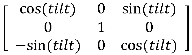
팬(Pan): x-y 평면에서의 오리엔테이션은 z-축을 중심으로 하는 회전 팬에 의해 제공된다. 여기서, 팬 Rpan은 
이러한 정의들로부터, R은 다음과 같이 표현될 수 있다:From these definitions, R can be expressed as:

이미지 내에서 검출된 소멸 포인트들은 3개의 직교 방향들에 따르는 것으로 정의된다. 여기서, 이미지는 3개의 소멸 포인트들: x-축 상에서의 (u1, v1), y-축 상에서의 (u2, v2) 및 깊이 또는 z-축 상에서의 (u3, v3)를 가지는 것으로 정의된다. 이 소멸 포인트들에 대해, 다음의 수식이 도출된다:
The extinction points detected in the image are defined as following three orthogonal directions. Here, the image has three extinction points: (u 1 , v 1 ) on the x-axis, (u 2 , v 2 ) on the y-axis and (u 3 , v 3 ) Lt; / RTI > For these vanishing points, the following equation is derived:

카메라가 정방형 픽셀(square pixel)들 및 제로 스큐(zero skew)를 가진다고 가정하면, 임의의 스케일 팩터들로서 λi의 정의에 기초하여, 다음의 수식이 추가로 도출된다:
Assuming that the camera has square pixels and zero skew, based on the definition of? I as any scale factors, the following formula is further derived:

상기 수식으로부터, 회전각 R은 다음의 수식에 따라 도출된다:
From the above equation, the rotation angle R is derived according to the following equation:

위의 내용에서, R은 추가적으로 행렬 R = [rl r2 r3]에 대응하고, 컴포넌트들 rl, r2, r3 각각은 R의 열(column)에 대응한다. R의 이러한 표현식으로부터, 회전 행렬 및 연관된 회전각은 주어진 3개의 소멸 포인트들 (u1 , v1), (u2 , v2 ), (u3 , v3)로 추정될 수 있다. 유닛 놈(unit norm)의 R의 각각의 열을 이루기 위해 i = 1 , 2, 3에 대한 파라미터들 λi가 선택된다.In the above, R additionally corresponds to the matrix R = [rl r2 r3], and each of the components rl, r2 and r3 corresponds to a column of R. From this expression of R, the rotation matrix and the associated rotation angle can be estimated as given three annihilation points (u 1 , v 1 ), (u 2 , v 2 ), (u 3 , v 3 ). The parameters λ i for i = 1, 2, 3 are chosen to form each row of R of the unit norm.
위의 내용으로부터, 이미지 내에서 식별된 2개의 소멸 포인트들이 주어지면, 카메라 회전각, 팬, 기울기 및 롤의 정확한 컴퓨테이션이 계산될 수 있다. 예를 들어, 도 6b에서의 이미지(402)를 다시 참조하면, 계산들은 이미지(402) 위에서 컨버징(converge)하는 수직 라인들(407)의 수직 소멸 포인트(406) 및 이미지(402)의 우측으로 컨버징하는 수평 라인들(405)의 수평 소멸 포인트(404)에 관하여 수행될 수 있다. 이미지 내에서의 에지 라인 피처들에 따라, 제 2 수평 소멸 포인트가 또한 식별 및 이용될 수 있다. 3D 좌표 축들(이미지에서의 x,y,z 및 u,v,깊이)은 수직이기 때문에, 2개의 소멸 포인트들이 공지되면, 제 3 소멸 포인트의 위치는, 공지된 소멸 포인트들에 기초하여 컴퓨팅될 수 있으며, 예를 들어, r3 = r1 x r2이다.From the above, the exact computation of camera rotation angle, pan, slope and roll can be computed, given the two extinction points identified in the image. For example, referring back to
회전 행렬의 정규화를 위해, 다음의 정의가 이루어진다:
For the normalization of the rotation matrix, the following definition is made:

카메라의 수평 축이 그라운드(ground)와 평행하게 유지되는 이미지들에 대해, pan = 0이다. 이러한 경우, R은 다음과 같이 간략화될 수 있다:
For images where the horizontal axis of the camera is kept parallel to the ground, pan = 0. In this case, R can be simplified as:

x-y 평면에서의 2차원 맵에서 포지션이 계산되는 구현들에 대해, 롤 각이 추정된다. 여기서, 위의 계산들은 x-축을 중심으로 회전하는 y-z 평면을 따르는 회전인 롤 각을 결정하기 위해 이용된다. 이러한 회전의 예는 도 8a-8b의 도면들(500, 502)에 의해 도시된다.For implementations where the position is computed in a two-dimensional map in the x-y plane, the roll angle is estimated. Here, the above calculations are used to determine the roll angle, which is the rotation along the y-z plane that rotates about the x-axis. An example of such a rotation is illustrated by Figures 500 and 502 of Figures 8a-8b.
추정은 카메라 회전 상태들의 별개의 세트 내에 주어질 수 있다. 예를 들어, 그라운드와 평행하게 또는 그라운드 아래로(또는 예를 들어, +15, 0 또는 -15 도) 예를 들어, 기울어진(tilted up) 가능한 기울기 상태들이 주어지면, 롤 각이 추정될 수 있다. 특히, 카메라의 기울기 각 또는 기울기 각의 부호(sign)(예를 들어, 포지티브 (상향(upward)) 기울기 또는 네거티브 (하향(downward)) 기울기)는 결정된 이미지 피처들, 카메라 센서 데이터 등에 기초하여 추정된다. 이러한 추정에 기초하여, 다음의 정의들이 이용된다:
The estimate may be given in a separate set of camera rotation states. For example, given tilt states that are tilted up parallel to or below ground (or, for example, +15, 0 or -15 degrees), the roll angle can be estimated have. In particular, a sign (e.g., a positive (upward) slope or a negative (downward) slope) of the tilt angle or tilt angle of the camera is estimated based on the determined image features, camera sensor data, do. Based on this estimate, the following definitions are used:

기울기 및 롤 각들이 -90 내지 +90 도들 내에 있으면, λ1의 부호는 (u1 - u0)에 의해 결정되고, λ2의 부호는 (v2 - v0)에 의해 결정된다. 이것은 (예를 들어, 좌측 또는 우측으로부터 보여지는) 롤의 대략적 추정(rough estimation)을 제공한다. 단지 수직 방향으로의 소멸 포인트만이 검출되면, 롤의 범위는 위와 유사한 방식으로 결정될 수 있다.If in the tilt and roll angle are also -90 to +90, the sign of λ 1 is - is determined by the (u 1 u 0), the sign of λ 2 is - is determined by the (v 2 v 0). This provides a rough estimation of the roll (viewed from the left or right, for example). If only the extinction point in the vertical direction is detected, the range of rolls can be determined in a similar manner as above.
위에서 설명된 기법들과 더불어, 이미지에 관하여 카메라의 회전은 카메라와 연관된 오리엔테이션 센서들(예를 들어, 가속도계, 자이로스코프들 등)을 통해 적어도 부분적으로 결정될 수 있다. 따라서, 위의 예에서, 어스(earth)에 관한 카메라의 기울기 또는 기울기의 방향(예를 들어, 상향 또는 하향)은 이미지 데이터와 더불어 또는 이미지 데이터 대신에 가속화 데이터로부터 컴퓨팅될 수 있다. 예를 들어, 센서들로부터의 정보를 이용하여 결정되는 중력 벡터는 위에서 설명되고 도 8에 도시된 바와 같이, 카메라의 기울기 및/또는 팬을 컴퓨팅하기 위해 이용될 수 있다. 추가적으로, 이미지에 관하여 카메라의 회전을 결정하기 위해 이용되는 정보의 적어도 일부가 이미지 그 자체 이외의 다른 수단에 의해 획득될 수 있다. 예를 들어, 이러한 정보는, 예를 들어, 네트워크 측정들을 히트맵 또는 시그니처 데이터와 비교함으로써, 위에서 제공된 바와 같은 네트워크 측정들로부터 획득될 수 있다.In addition to the techniques described above, the rotation of the camera with respect to the image may be determined, at least in part, via orientation sensors (e.g., accelerometers, gyroscopes, etc.) associated with the camera. Thus, in the example above, the tilt or tilt direction (e.g., upward or downward) of the camera with respect to the earth may be computed from the acceleration data with or instead of the image data. For example, a gravity vector determined using information from the sensors can be used to compute the tilt and / or pan of the camera, as described above and shown in FIG. Additionally, at least some of the information used to determine the rotation of the camera with respect to the image may be obtained by means other than the image itself. For example, such information may be obtained from network measurements, for example, as provided above, e.g., by comparing network measurements with a heat map or signature data.
또 다른 예로서, 다수의 타겟들 또는 표면들이 식별되는 이미지들에 대해, 검출된 타겟들 및/또는 표면들 각각에 관한 정보가 카메라의 회전 추정치를 추가로 정제하기 위해 이용될 수 있다. 예를 들어, 교차 벽(intersecting wall)들 또는 내부 또는 외부 코너와 같은 2개 또는 그 초과의 비평행 벽(wall)들을 도시하는 이미지에 대한 프로세싱은 검출된 벽들 각각에 대한 에지 라인 피처들 및 소멸 포인트들에 대응하는 정보를 추출함으로써 진행될 수 있다. 후속적으로, 검출된 에지 라인 피처들 및 소멸 포인트들 각각에 대응하는 결정된 정보는 위에서 설명된 바와 같이, 카메라의 회전 추정치의 정확도를 개선(enhance)하기 위해 이용될 수 있다.As another example, for images in which multiple targets or surfaces are identified, information about each of the detected targets and / or surfaces may be used to further refine the camera's rotation estimate. For example, processing for an image showing two or more non-parallel walls, such as intersecting walls or inner or outer corners, may result in edge line features for each of the detected walls and extinction By extracting information corresponding to the points. Subsequently, the determined information corresponding to each of the detected edge line features and vanishing points can be used to enhance the accuracy of the camera's rotation estimate, as described above.
위에서 설명된 기법들은 카메라(135)에 의해 캡처된 임의의 주어진 이미지가 관심있는 하나의 오브젝트를 포함하는 시나리오에 적용될 수 있다. 다수의 오브젝트들이 이미지에 존재하고, 오브젝트들이 둘러싸는 환경에서 서로 다른 벽들과 연관되면, 오브젝트들 각각에 대응하는 소멸 포인트들은 위에서 설명된 계산들을 돕기 위해 식별 및 이용될 수 있다.The techniques described above can be applied to scenarios in which any given image captured by the
위에서 설명된 기법들을 이용함으로써, 심지어 컴퓨터 비전 검출로부터의 핵심 포인트들의 수 및/또는 배치가 그들 자신에 대한 포즈 추정에 충분하지 않을 때에도, 카메라 포즈의 견고한 대략적 추정이 2D 맵에 관하여 수행될 수 있다. 단지 수평 소멸 포인트만으로 또는 다수의 소멸 포인트들로 스토어프론트(storefront) 또는 다른 타겟으로의 카메라 회전의 대략적 추정이 수행될 수 있다. 추가로, 추정은 검출된 라인들에서의 특정한 양의 결함(imperfection)을 허용(tolerate)할 수 있다. 포지셔닝을 목적으로, 맵이 이용되면, 본 명세서에 설명된 추정은 포지셔닝 정확도의 상당한 개선을 야기한다.By using the techniques described above, a robust coarse estimation of the camera pose can be performed with respect to the 2D map, even when the number and / or placement of key points from computer vision detection is not sufficient for pose estimation on themselves . A rough estimation of the camera rotation to the storefront or other target can be performed only with horizontal decay points or with multiple decay points. In addition, the estimate may tolerate a certain amount of imperfection in the detected lines. If a map is used for positioning purposes, the estimation described herein leads to a significant improvement in positioning accuracy.
위에서 논의된 바와 같이, 스토어프론트 간판(storefront sign) 또는 다른 POI가 검출된 이후, 포즈 추정은 POI 그 자체 대신에, 바닥, 지붕 등의 에지들과 같은, POI 주위의 라인(line)들에 기초하여 수행된다. 카메라 뷰의 위치는 검출된 이미지의 평면과 평행하는 문들, 지붕 및/또는 바닥 라인들에 기초하여 추정될 수 있다. 관련 카메라 파라미터들이 공지될 때, 정확한 소멸 포인트 포지션(들)이 팬 및 기울기 각들을 계산하기 위해 이용될 수 있다. 카메라 파라미터들이 공지될 때, 대략적 추정(예를 들어, 좌측, 우측, 상부 또는 하부로부터의 뷰)이 수행될 수 있다.As discussed above, after a storefront sign or other POI is detected, the pose estimation may be based on the lines around the POI, such as bottoms, roof edges, etc., instead of the POI itself . The position of the camera view may be estimated based on doors, roof and / or floor lines that are parallel to the plane of the detected image. When relevant camera parameters are known, the correct extinction point position (s) can be used to calculate the pan and tilt angles. When camera parameters are known, approximate estimates (e.g., views from the left, right, top, or bottom) may be performed.
도 9는 위에서 설명된 바와 같은 카메라 포즈 추정 기법들을 이용할 수 있는 포지셔닝 시스템(600)을 예시한다. 시스템(600)은, 공지된 오브젝트들을 시각적으로 탐색하고 이들을 영역 내에서의 사용자의 위치가 결정될 수 있는 맵 상의 POI들에 매칭시킴으로써 동작한다. 예를 들어, 시스템(600)은 서로 다른 리테일러(retailer)들에 대한 로고(logo)들을 시각적으로 탐색하고, 로고들을 쇼핑 몰 내에서의 위치들에 매칭시키며, 결정된 위치들에 기초하여 사용자의 포지션을 결정함으로써, 쇼핑 몰 내에서의 사용자의 포지션을 추정할 수 있다. 대안적으로, 사용자는 영역내에서의 다양한 장소들의 이미지들뿐만 아니라, 이미지들 각각 내에서 로케이팅된 POI들의 식별들을 제공할 수 있다.FIG. 9 illustrates a
시스템(600)을 이용하기 위해, 사용자는, 로케이팅될 디바이스와 연관된 카메라를 활성화하며, 예를 들어, 환경들(surroundings) 주위에서 디바이스의 패닝(panning), 디바이스가 고정되어 있는 동안의 하나 또는 그 초과의 이미지들의 캡처 등에 의해 자신의 환경에 대한 하나 또는 그 초과의 이미지들을 캡처한다. 결과적 카메라 입력(602)은 중간 포지셔닝 모듈(606)에 전달되고, 이 중간 포지셔닝 모듈(606)은, 카메라 뷰로부터의 로고들 및/또는 다른 오브젝트들을 식별하고, POI 또는 시각적 시그니처 데이터베이스들, 영역과 연관된 맵 제약 데이터 등을 포함하는 보조 데이터(604)에 기초하여 이러한 오브젝트들을 POI들과 비교한다. 오브젝트 식별은 이미지 피처 추출 및 매칭 및/또는 임의의 다른 기법(들)에 기초하여 수행될 수 있다. 오브젝트들을 매칭시킬 시 문제점들에 당면하게 되는 경우, 사용자에게는 패닝을 늦추는 것, 더 큰 반경을 패닝하는 것 등과 같은, 재획득 카메라 입력(602)에 대한 피드백이 주어질 수 있다.To use the
중간 포지셔닝 모듈은 보조 데이터(604)에 따라, 검출된 POI들을 그들의 위치들에 매칭시킨다. 중간 포지셔닝 모듈은 또한, 위에서 논의된 바와 같이, POI들의 각각의 이미지들과 연관된 회전각들을 결정한다. 이러한 위치들, 연관된 카메라 회전각들 및 보조 데이터(604)와 연관된 맵 제약들에 기초하여, 디바이스의 중간 위치가 추정된다. 예를 들어, 사용자 위치는, 맵 제약들, 카메라가 POI를 비추는 각 및 POI의 공지된 위치에 기초한, 검출된 POI가 가시적이게 하는 가능한 영역에 기초하여 추정될 수 있다. 다른 기법들이 또한 가능하다. 이러한 중간 위치는 포지셔닝 엔진(610)에 제공되고, 이 포지셔닝 엔진(610)은, 하나 또는 그 초과의 오리엔테이션 센서들(612)(예를 들어, 가속도계, 자이로스코프, 콤파스(compass) 등)로부터 획득된 측정들, 네트워크-기반 포지셔닝 모듈(614)을 통해 Wi-Fi 네트워크 또는 다른 무선 통신 네트워크로부터 획득된 네트워크 측정들(예를 들어, RSSI(received signal strength indication), RTT(round trip time) 등) 등과 같은 다른 포지션 위치 데이터와 중간 위치를 결합한다. 카메라와 각각의 검출된 POI들 간의 거리는 또한, 예를 들어, 카메라 이미지(imagery) 내에서의 POI의 크기, 카메라의 줌 팩터(zoom factor), 카메라의 오리엔테이션, POI의 공지된 크기 등에 기초하여 계산 또는 추정될 수 있으며, 포지셔닝 엔진(610)에 추가로 제공될 수 있다. 포지셔닝 엔진(610)은 결합된 포지션 위치 데이터를 이용하여 디바이스에 대한 최종 포지션 추정치를 획득한다. 포지셔닝 엔진(610)은 중간 포지셔닝 모듈(606), 오리엔테이션 센서(들)(612) 및 네트워크 기반 포지셔닝 모듈(614)로서 도시되지만, 포지셔닝 엔진(610)은 모든 이러한 소스들보다 적은 소스들로부터 데이터를 획득할 수 있고 그리고/또는 포지셔닝 모듈(610)은 예시되지 않은 다른 소스들로부터 데이터를 획득할 수 있다.The intermediate positioning module matches the detected POIs to their locations according to the
시스템(600)은 모바일 디바이스(12)에 의해 구현될 수 있다. 예를 들어, 오리엔테이션 센서(들)(612)는 오리엔테이션 센서(들)(132) 및 카메라 입력(602)일 수 있고, 맵 제약들/보조 데이터(604), 중간 포지셔닝 모듈(606), 포지셔닝 엔진(610) 및 네트워크 기반 포지셔닝 모듈(614)은 범용 프로세서(111) 및/또는 DSP(112), 메모리(140) 및 카메라(135)에 의해 제공 및/또는 구현될 수 있다.The
도 10을 참조하면, 도 1-9를 추가로 참조하여, 이미지에 대응하는 카메라 포즈를 추정하는 프로세스(700)가, 도시된 스테이지들을 포함한다. 그러나, 프로세스(700)는 제한이 아닌 예일 뿐이다. 프로세스(700)는, 예를 들어, 스테이지들이 부가, 제거, 재배열, 결합 및/또는 동시에 수행되게 함으로써 변경될 수 있다. 도시 및 설명된 바와 같은 프로세스(700)에 대한 여전히 다른 변경들이 가능하다.Referring to Fig. 10, with further reference to Figs. 1-9, a
스테이지(702)에서, 영역 내에서의 스토어프론트와 같은, 장소의 이미지는 카메라(135)를 이용하여 캡처된다. 이미지는 타겟 오브젝트(예를 들어, 스토어프론트 로고) 및 타겟 오브젝트 외부의 에지 라인 피처들을 포함한다. 바닥 또는 지붕, 문들, 윈도우들 등과 같은, 타겟 오브젝트를 둘러싸는 장소의 피처들로부터, (예를 들어, 에지 추출기(302)에 의해) 주변 에지 라인 피처들이 도출된다.At
스테이지(704)에서, 스테이지(702)에서 캡처된 이미지로부터의 에지 라인 피처들과 연관된 하나 또는 그 초과의 소멸 포인트들이, 예를 들어, 소멸 포인트 추정기(304)에 의해 추정된다.At
스테이지(706)에서, 카메라(135)의 포즈 또는 이동 방향은 스테이지(702)에서 검출된 에지 피처들 및/또는 스테이지(704)에서 추정된 하나 또는 그 초과의 소멸 포인트들에 기초하여 타겟 오브젝트에 관하여 (예를 들어, 모듈(306)과 같은 회전 행렬 컴퓨테이션 모듈에 의해) 계산된다. 스테이지(706)에서 수행된 계산들의 특성(nature)은 스테이지(704)에서 식별된 소멸 포인트들의 수에 의존할 수 있다. 예를 들어, 하나의 소멸 포인트가 스테이지(704)에서 식별되면, 카메라 회전의 대략적 추정이 스테이지(706)에서 수행될 수 있다. 대안적으로, 2개 또는 그 초과의 소멸 포인트들이 스테이지(704)에서 식별되면, 카메라 회전은 더 높은 정확도로 706에서 계산될 수 있다. 위에서 논의된 바와 같이, 스테이지(706)에서의 계산들에서, 오리엔테이션 센서들에 의해 제공되는 가속화 데이터와 같은 다른 정보가 또한 이용될 수 있다. 스테이지(706)에서의 계산들의 완료 시, 실내 포지셔닝 정확도를 개선하기 위해 그리고/또는 위에서 제공된 바와 같은 다른 목적들을 위해, 계산된 카메라 포즈가 이용될 수 있다.At
도 11에 예시된 바와 같은 컴퓨터 시스템(800)은 도 2, 3 및 9에 도시된 디바이스들과 같은 앞서 설명된 컴퓨터화된 디바이스들의 기능 및/또는 컴포넌트들을 적어도 부분적으로 구현하기 위해 이용될 수 있다. 도 11은, 본 명세서에 설명된 바와 같은, 다양한 실시예들에 의해 제공되는 방법들을 수행할 수 있고 그리고/또는 모바일 디바이스 또는 다른 컴퓨터 시스템으로서 기능할 수 있는 컴퓨터 시스템(800)의 일 실시예의 개략도를 제공한다. 도 11은 다양한 컴포넌트들의 일반화된 도면을 제공하며, 이들 전부 또는 이들 중 임의의 것이 적절하게 이용될 수 있다. 따라서, 도 11은 개별 시스템 엘리먼트들이, 비교적 분리되거나 또는 비교적 더 통합된 방식으로, 어떻게 구현될 수 있는지를 광범위하게 예시한다.A
버스(805)를 통해 전기적으로 커플링될 수 있는(또는 그렇지 않으면, 적절하게 통신할 수 있는) 하드웨어 엘리먼트들을 포함하는 컴퓨터 시스템(800)이 도시된다. 하드웨어 엘리먼트들은, (제한없이, 하나 또는 그 초과의 범용 프로세서들 및/또는 하나 또는 그 초과의 특수 목적 프로세서들(이를테면, 디지털 신호 프로세싱 칩들, 그래픽 가속 프로세서들 등)을 포함하는) 하나 또는 그 초과의 프로세서들(810), (제한없이, 마우스, 키보드 등을 포함할 수 있는) 하나 또는 그 초과의 입력 디바이스들(815), 및 (제한없이, 디스플레이 디바이스, 프린터 등을 포함할 수 있는) 하나 또는 그 초과의 출력 디바이스들(820)을 포함할 수 있다. 프로세서(들)(810)는, 예를 들어, 지능형 하드웨어 디바이스들, 예를 들어, Intel® Corporation 또는 AMD®에 의해 제조된 것들과 같은 CPU(central processing unit), 마이크로제어기, ASIC 등을 포함할 수 있다. 다른 프로세서 타입들이 또한 이용될 수 있다.A
컴퓨터 시스템(800)은, (제한없이, 로컬 및/또는 네트워크 액세스가능한 스토리지를 포함할 수 있고, 그리고/또는 제한없이, 디스크 드라이브, 드라이브 어레이, 광 저장 디바이스, 고체-상태 저장 디바이스, 이를테면, 프로그램가능하고, 플래쉬-업데이트가능한 식일 수 있는 랜덤 액세스 메모리("RAM") 및/또는 판독-전용 메모리("ROM")를 포함할 수 있는) 하나 또는 그 초과의 비-일시적 저장 디바이스들(825)을 더 포함할 수 있다(그리고/또는 이들과 통신할 수 있다). 이러한 저장 디바이스들은 (제한없이, 다양한 파일 시스템들, 데이터베이스 구조들 등을 포함하는) 임의의 적절한 데이터 저장소들을 구현하도록 구성될 수 있다.
컴퓨터 시스템(800)은 또한, (제한없이, 모뎀, 네트워크 카드(무선 또는 유선), 적외선 통신 디바이스, 무선 통신 디바이스 및/또는 칩셋(이를테면, 블루투스™ 디바이스, 802.11 디바이스, WiFi 디바이스, WiMax 디바이스, 셀룰러 통신 설비들 등) 등을 포함할 수 있는) 통신 서브시스템(830)을 포함할 수 있다. 통신 서브시스템(830)은 데이터가, 네트워크(이를테면, 일례만 들자면, 아래에서 설명된 네트워크), 다른 컴퓨터 시스템들, 및/또는 본 명세서에 설명된 임의의 다른 디바이스들과 교환되게 할 수 있다. 많은 실시예들에서, 컴퓨터 시스템(800)은, 여기에서와 같이, 위에서 설명된 바와 같은 RAM 또는 ROM 디바이스를 포함할 수 있는 작업 메모리(835)를 더 포함할 것이다.The
컴퓨터 시스템(800)은 또한, 운영 시스템(840), 디바이스 드라이버들, 실행가능한 라이브러리들, 및/또는 다른 코드, 이를테면, 본 명세서에 설명된 바와 같이, 다양한 실시예들에 의해 제공되는 컴퓨터 프로그램들을 포함할 수 있고, 그리고/또는 다른 실시예들에 의해 제공되는 방법들을 구현하고, 그리고/또는 시스템들을 구성하도록 설계될 수 있는 하나 또는 그 초과의 애플리케이션 프로그램들(845)을 비롯하여, 작업 메모리(835) 내에 현재 위치되어 있는 것으로 도시된 소프트웨어 엘리먼트들을 포함할 수 있다. 단지 예로서, 본 명세서에 설명된 하나 또는 그 초과의 프로세스들은 컴퓨터(및/또는 컴퓨터 내의 프로세서)에 의해 실행가능한 코드 및/또는 명령들로 구현될 수 있다. 이러한 코드 및/또는 명령들은, 설명된 방법들에 따라, 하나 또는 그 초과의 동작들을 수행하도록 범용 컴퓨터(또는 다른 디바이스)를 구성하고 그리고/또는 적응시키는데 이용될 수 있다.The
이 명령들 및/또는 코드의 세트는, 위에서 설명된 저장 디바이스(들)(825)와 같은 컴퓨터 판독가능한 저장 매체 상에 저장될 수 있다. 일부 경우들에서, 저장 매체는 컴퓨터 시스템, 이를테면, 시스템(800) 내에 포함될 수 있다. 다른 실시예들에서, 저장 매체는 컴퓨터 시스템(예를 들어, 이동식(removable) 매체, 이를테면, 컴팩트 디스크(disc))과 별개일 수도 있고, 그리고/또는 저장 매체가 저장 매체 상에 저장된 명령들/코드로 범용 컴퓨터를 프로그래밍하고, 구성하고 그리고/또는 적응시키는데 이용될 수 있도록 설치 패키지로 제공될 수 있다. 이 명령들은 컴퓨터 시스템(800)에 의해 실행가능한 실행가능 코드의 형태를 취할 수 있고, 그리고/또는 (그 다음, 컴퓨터 시스템(800) 상에서의 컴파일(compilation) 및/또는 설치(installation) 시에, (예를 들어, 다양한 일반적으로 이용가능한 컴파일러들, 설치 프로그램들, 압축/압축해제 유틸리티들 등 중 임의의 것을 이용하여) 실행가능한 코드의 형태를 취하는) 소스 및/또는 설치가능한 코드의 형태를 취할 수 있다.These sets of instructions and / or code may be stored on a computer-readable storage medium, such as the storage device (s) 825 described above. In some cases, the storage medium may be contained within a computer system, such as
특정 요구들에 따라 상당한 변화들이 이루어질 수 있다. 예를 들어, 커스터마이징된 하드웨어가 또한 이용될 수 있고, 그리고/또는 특정한 엘리먼트들이 하드웨어, 소프트웨어(애플릿들과 같은 휴대용 소프트웨어 등을 포함함) 또는 둘 다로 구현될 수 있다. 추가로, 네트워크 입력/출력 디바이스들과 같은 다른 컴퓨팅 디바이스들로의 연결이 이용될 수 있다.Significant changes can be made according to specific needs. For example, customized hardware may also be utilized, and / or certain elements may be implemented in hardware, software (including portable software such as applets), or both. In addition, connections to other computing devices such as network input / output devices may be utilized.
컴퓨터 시스템(이를테면, 컴퓨터 시스템(800))은 본 개시에 따라 방법들을 수행하기 위해 이용될 수 있다. 작업 메모리(835)에 포함되는 (운영 시스템(840) 및/또는 다른 코드, 이를테면, 애플리케이션 프로그램(845)에 포함될 수 있는) 하나 또는 그 초과의 명령들의 하나 또는 그 초과의 시퀀스들을 실행하는 프로세서(810)에 응답하여, 이러한 방법들의 프로시저들의 일부 또는 전부가 컴퓨터 시스템(800)에 의해 수행될 수 있다. 이러한 명령들은 다른 컴퓨터 판독가능한 매체, 이를테면, 저장 디바이스(들)(825) 중 하나 또는 그 초과의 저장 디바이스(들)로부터 작업 메모리(835)로 판독될 수 있다. 단지 예로서, 작업 메모리(835) 내에 포함된 명령들의 시퀀스들의 실행은 프로세서(들)(810)로 하여금 본 명세서에 설명된 방법들의 하나 또는 그 초과의 프로시저들을 수행하게 할 수 있다.A computer system (e.g., computer system 800) may be utilized to perform the methods in accordance with the present disclosure. A processor executing one or more sequences of one or more instructions contained in working memory 835 (which may be included in
본 명세서에 이용되는 바와 같은 "기계 판독가능한 매체" 및 "컴퓨터 판독가능한 매체"라는 용어들은, 기계로 하여금 특정 방식으로 동작하게 하는 데이터를 제공하는데 참여하는 임의의 매체를 지칭한다. 컴퓨터 시스템(800)을 이용하여 구현되는 실시예에서, 다양한 컴퓨터 판독가능한 매체들이, 실행을 위한 명령들/코드를 프로세서(들)(810)에 제공하는데 수반될 수 있고, 그리고/또는 (예를 들어, 신호들과 같은) 이러한 명령들/코드를 저장 및/또는 전달하는데 이용될 수 있다. 많은 구현들에서, 컴퓨터 판독가능한 매체는 물리 그리고/또는 유형의 저장 매체이다. 이러한 매체는 비-휘발성 매체들, 휘발성 매체들 및 송신 매체들을 포함하는(그러나, 이에 제한되는 것은 아님) 많은 형태들을 취할 수 있다. 비-휘발성 매체들은, 예를 들어, 광 그리고/또는 자기 디스크들, 이를테면, 저장 디바이스(들)(825)를 포함한다. 휘발성 매체들은, 제한없이, 동적 메모리, 이를테면, 작업 메모리(835)를 포함한다. 송신 매체들은, 제한없이, 버스(805) 뿐만 아니라 통신 서브시스템(830)의 다양한 컴포넌트들 (및/또한 통신 서브시스템(830)이 다른 디바이스들과의 통신이 제공되게 하는 매체들)을 포함하는 와이어들을 포함하는 동축 케이블들, 구리 유선 및 광섬유들을 포함한다. 따라서, 송신 매체들은 또한, (제한없이, 라디오파(radio-wave) 및 적외선 데이터 통신들 동안 생성된 것들과 같은 라디오, 어쿠스틱(acoustic) 및/또는 광파들을 포함하는) 파들의 형태를 취할 수 있다.The terms "machine-readable medium" and "computer-readable medium" as used herein refer to any medium that participates in providing data that causes the machine to operate in a particular manner. In an embodiment implemented using
물리적 그리고/또는 유형의 컴퓨터 판독가능한 매체들의 일반적인 형태들은, 예를 들어, 플로피 디스크, 플렉서블 디스크, 하드 디스크, 자기 테이프 또는 임의의 다른 자기 매체, CD-ROM, 블루-레이 디스크, 임의의 다른 광 매체, 펀치 카드들(punch cards), 페이퍼테이프(papertape), 홀들의 패턴들을 갖는 임의의 다른 물리 매체, RAM, PROM, EPROM, FLASH-EPROM, 임의의 다른 메모리 칩 또는 카트리지, 이하에 설명되는 바와 같은 반송파 또는 컴퓨터가 명령들 및/또는 코드를 판독할 수 있는 임의의 다른 매체를 포함한다.Common forms of physical and / or computer readable media of the type include, for example, a floppy disk, a flexible disk, a hard disk, a magnetic tape or any other magnetic medium, a CD-ROM, a Blu-ray disk, Any other physical medium having patterns of holes, a RAM, a PROM, an EPROM, a FLASH-EPROM, any other memory chip or cartridge, as described below The same carrier or any other medium from which a computer can read instructions and / or code.
다양한 형태들의 컴퓨터 판독가능한 매체들은 실행을 위한 하나 또는 그 초과의 명령들의 하나 또는 그 초과의 시퀀스들을 프로세서(들)(810)에 전달하는데 수반될 수 있다. 단지 예로서, 명령들은 초기에, 원격 컴퓨터의 자기 디스크 및/또는 광 디스크 상에서 전달될 수 있다. 원격 컴퓨터는 그것의 동적 메모리에 명령들을 로딩하며, 컴퓨터 시스템(800)에 의해 수신 및/또는 실행되도록 송신 매체 상에서 신호들로서 명령들을 전송할 수 있다. 전자기파 신호들, 어쿠스틱 신호들, 광학 신호들 등의 형태일 수 있는 이러한 신호들은 본 발명의 다양한 실시예들에 따라, 명령들이 인코딩될 수 있는 반송파들의 모든 예들이다.Various forms of computer-readable media may be involved in communicating one or more sequences of one or more instructions for execution to processor (s) 810. [ By way of example only, the instructions may initially be delivered on a magnetic disk and / or an optical disk of a remote computer. The remote computer may load instructions into its dynamic memory and transmit the instructions as signals on the transmission medium to be received and / or executed by the
통신 서브시스템(830)(및/또는 이것의 컴포넌트들)은 일반적으로 신호들을 수신할 것이고, 그 다음, 버스(805)는 신호들(및/또는 신호들에 의해 전달되는 데이터, 명령들 등)을 작업 메모리(835)에 전달할 수 있고, 프로세서(들)(805)는 이 작업 메모리(835)로부터의 명령들을 리트리브 및 실행한다. 작업 메모리(835)에 의해 수신된 명령들은 프로세서(들)(810)에 의한 실행 이전에 또는 이후에 저장 디바이스(825) 상에 선택적으로 저장될 수 있다.The communication subsystem 830 (and / or its components) will typically receive signals, and then the
위에서 논의된 방법들, 시스템들 및 디바이스들은 예들이다. 다양한 대안적 구성들은 적절하게 다양한 프로시저들 또는 컴포넌트들을 생략, 치환 또는 부가할 수 있다. 예를 들어, 대안적인 방법들에서, 스테이지들은 위에서의 논의와 서로 다른 순서들로 수행될 수 있고 다양한 스테이지들이 부가, 생략 또는 결합될 수 있다. 또한, 특정 구성들에 관하여 설명된 특징들은 다양한 다른 구성들에서 결합될 수 있다. 구성들의 서로 다른 양상들 및 엘리먼트들은 유사한 방식으로 결합될 수 있다. 또한, 기술은 진화하고, 따라서, 많은 엘리먼트들이 예들이며, 본 개시 또는 청구항들의 범위를 제한하지 않는다.The methods, systems and devices discussed above are examples. Various alternative arrangements may appropriately omit, replace, or append various procedures or components. For example, in alternative methods, the stages may be performed in different orders from those discussed above, and various stages may be added, omitted, or combined. In addition, features described with respect to particular configurations may be combined in various other configurations. Different aspects and elements of the arrangements may be combined in a similar manner. Also, the technology evolves, and thus, many elements are examples and do not limit the scope of the disclosure or the claims.
구체적인 세부사항들이 (구현들을 포함하는) 예시적 구성들의 완전한 이해를 제공하기 위해 설명에 주어진다. 그러나, 구성들은 이러한 구체적인 세부사항들 없이 실시될 수 있다. 예를 들어, 공지된 회로들, 프로세스들, 알고리즘들, 구조들 및 기법들은 구성들을 모호하게 하는 것을 회피하기 위해 불필요한 세부사항 없이 나타낸다. 이러한 설명은 단지 예시적 구성들만을 제공하며, 청구항들의 범위, 구성들 또는 적용가능성을 제한하지 않는다. 오히려, 구성들의 상기 설명은 설명된 기법들을 구현하기 위한 가능한 설명을 당업자들에게 제공할 것이다. 본 개시의 사상 또는 범위로부터 벗어나지 않으면서 엘리먼트들의 배열 및 기능에서 다양한 변화들이 이루어질 수 있다.The specific details are given in the description to provide a thorough understanding of exemplary configurations (including implementations). However, configurations may be practiced without these specific details. For example, well-known circuits, processes, algorithms, structures and techniques are shown without unnecessary detail in order to avoid obscuring the configurations. This description merely provides exemplary configurations, and does not limit the scope, configurations, or applicability of the claims. Rather, the foregoing description of the arrangements will provide those skilled in the art with a possible explanation for implementing the techniques described. Various changes may be made in the arrangement and functioning of elements without departing from the spirit or scope of the disclosure.
구성들은 흐름도 또는 블록도로서 도시되는 프로세스로서 설명될 수 있다. 각각은 순차적 프로세스로서 동작들을 설명할 수 있지만, 동작들 중 다수는 병렬로 또는 동시에 수행될 수 있다. 또한, 동작들의 순서가 재배열될 수 있다. 프로세스는 도면에 포함되지 않는 추가 단계들을 가질 수 있다. 게다가, 방법들의 예들은 하드웨어, 소프트웨어, 펌웨어, 미들웨어, 마이크로코드, 하드웨어 기술어들 또는 이들의 임의의 결합에 의해 구현될 수 있다. 소프트웨어, 펌웨어, 미들웨어 또는 마이크로 코드로 구현될 때, 필요한 태스크들을 수행하기 위한 프로그램 코드 또는 코드 세그먼트들은 저장 매체와 같은 비-일시적 컴퓨터 판독가능한 매체에 저장될 수 있다. 프로세서들은 설명된 태스크들을 수행할 수 있다.The configurations may be described as a process that is shown as a flowchart or a block diagram. Each may describe operations as a sequential process, but many of the operations may be performed in parallel or concurrently. Also, the order of operations can be rearranged. The process may have additional steps not included in the drawing. In addition, examples of methods may be implemented by hardware, software, firmware, middleware, microcode, hardware descriptors, or any combination thereof. When implemented in software, firmware, middleware or microcode, the program code or code segments for performing the required tasks may be stored in a non-transitory computer readable medium, such as a storage medium. The processors may perform the described tasks.
청구항들을 포함하는 본 명세서에서 이용되는 바와 같이, 예를 들어, "A, B 또는 C 중 적어도 하나"의 리스트가 A 또는 B 또는 C 또는 AB 또는 AC 또는 BC 또는 ABC(즉, A 및 B 및 C), 또는 하나 초과의 특징과의 결합들(예를 들어, AA, AAB, ABBC 등)을 의미하도록, "~중 적어도 하나"로 기술(preface)되는 아이템들의 리스트에서 이용되는 "또는"은 이접성(disjunctive) 리스트를 표시한다.For example, a list of "at least one of A, B, or C" is used as A or B or C or AB or AC or BC or ABC (i.e., A and B and C Quot; or "used " in a list of items that are prefaced with at least one of " to " to mean one or more combinations (e.g., AA, AAB, ABBC, Display a disjunctive list.
몇몇 예시적 구성들을 설명하였지만, 본 개시의 사상으로부터 벗어나지 않고 다양한 변경들, 대안적 구성들 및 등가물들이 이용될 수 있다. 예를 들어, 위의 엘리먼트들은 더 큰 시스템의 컴포넌트들일 수 있으며, 여기서 다른 규칙들이 본 발명의 애플리케이션보다 우선할 수도 있고 또는 그렇지 않으면 애플리케이션을 변경할 수도 있다. 또한, 다수의 단계들이 위의 엘리먼트들이 고려되기 이전에, 고려되는 동안에 또는 고려된 이후에 착수될 수 있다. 따라서, 위의 설명은 청구항들의 범위를 제한하지 않는다.
While several exemplary configurations have been described, various modifications, alternative constructions, and equivalents may be utilized without departing from the scope of the present disclosure. For example, the above elements may be components of a larger system, where other rules may take precedence over the application of the present invention, or otherwise modify the application. Also, a number of steps may be undertaken before, during, or after consideration of the above elements. Accordingly, the above description does not limit the scope of the claims.
Claims (40)
카메라를 통해 캡처된 장소(location)의 이미지를 획득하는 단계 ― 상기 이미지는 타겟 오브젝트 및 상기 타겟 오브젝트 외부의 에지 라인 피처들을 포함함 ― ;
알려진 기준 오브젝트들의 세트로부터, 식별된 타겟 오브젝트로서, 상기 타겟 오브젝트를 식별하는 단계;
상기 에지 라인 피처들과 연관된 하나 또는 그 초과의 소멸 포인트들을 추정하는 단계; 및
상기 에지 라인 피처들에 기초하여 상기 식별된 타겟 오브젝트에 관하여 상기 카메라의 포즈를 계산하는 단계를 포함하고,
상기 계산하는 단계는 상기 추정된 하나 또는 그 초과의 소멸 포인트들에 기초하여 상기 타겟 오브젝트에 관하여 상기 카메라의 포즈를 계산하는 단계를 포함하는,
카메라 포즈를 추정하기 위한 방법.A method for estimating a camera pose,
The method comprising: obtaining an image of a location captured via a camera, the image including a target object and edge line features outside the target object;
Identifying, as an identified target object, the target object from a set of known reference objects;
Estimating one or more vanishing points associated with the edge line features; And
And calculating a pose of the camera with respect to the identified target object based on the edge line features,
Wherein the calculating comprises calculating a pose of the camera with respect to the target object based on the estimated one or more vanishing points.
A method for estimating a camera pose.
상기 타겟 오브젝트를 식별하는 단계는 상기 카메라의 포즈를 계산하는 것과는 독립적으로, 컴퓨터 비전 알고리즘을 통해, 상기 타겟 오브젝트를 상기 알려진 기준 오브젝트들의 세트와 비교함으로써, 상기 타겟 오브젝트를 식별하는 단계를 포함하는,
카메라 포즈를 추정하기 위한 방법.The method according to claim 1,
Wherein identifying the target object comprises identifying the target object by comparing the target object with a set of known reference objects through a computer vision algorithm independently of calculating a pose of the camera.
A method for estimating a camera pose.
상기 식별하는 단계는 상기 이미지에서 상기 타겟 오브젝트의 핵심 포인트(key point)들을 검출하는 단계를 포함하는,
카메라 포즈를 추정하기 위한 방법.3. The method of claim 2,
Wherein the identifying comprises detecting key points of the target object in the image.
A method for estimating a camera pose.
사용자 입력으로부터 상기 이미지 내에서의 상기 타겟 오브젝트의 아이덴티티를 수신하는 단계를 더 포함하는,
카메라 포즈를 추정하기 위한 방법.The method according to claim 1,
Further comprising receiving from the user input the identity of the target object within the image,
A method for estimating a camera pose.
상기 이미지 내에서의 상기 에지 라인 피처들을 검출하는 단계를 더 포함하는,
카메라 포즈를 추정하기 위한 방법.The method according to claim 1,
Further comprising detecting the edge line features in the image.
A method for estimating a camera pose.
상기 에지 라인 피처들을 검출하는 단계는 수평 에지 라인 피처들 및 수직 에지 라인 피처들을 검출하는 단계를 포함하는,
카메라 포즈를 추정하기 위한 방법.The method according to claim 6,
Wherein detecting edge line features comprises detecting horizontal edge line features and vertical edge line features.
A method for estimating a camera pose.
상기 에지 라인 피처들을 검출하는 단계는 바닥(floor), 지붕(roof) 또는 문(door) 중 적어도 하나를 검출하는 단계를 포함하는,
카메라 포즈를 추정하기 위한 방법.8. The method of claim 7,
The step of detecting edge line features may include detecting at least one of a floor, a roof, or a door.
A method for estimating a camera pose.
상기 하나 또는 그 초과의 소멸 포인트들을 추정하는 단계는 상기 수평 에지 라인 피처들로부터 수평 소멸 포인트를 추정하는 단계 또는 상기 수직 에지 라인 피처들로부터 수직 소멸 포인트를 추정하는 단계 중 적어도 하나를 포함하는,
카메라 포즈를 추정하기 위한 방법.8. The method of claim 7,
Wherein estimating the one or more vanishing points comprises at least one of estimating a horizontal vanishing point from the horizontal edge line features or estimating a vertical vanishing point from the vertical edge line features.
A method for estimating a camera pose.
상기 하나 또는 그 초과의 소멸 포인트들을 추정하는 단계는, 하나의 소멸 포인트를 추정하는 단계를 포함하고; 그리고
상기 카메라의 포즈를 계산하는 단계는, 상기 하나의 추정된 소멸 포인트에 기초하여 상기 이미지에서의 검출가능한 오브젝트에 의해 정의되는 평면에 관하여 상기 카메라의 회전을 추정하는 단계를 포함하는,
카메라 포즈를 추정하기 위한 방법.The method according to claim 1,
Wherein estimating the one or more vanishing points comprises estimating a vanishing point; And
Wherein calculating the pose of the camera comprises estimating a rotation of the camera with respect to a plane defined by a detectable object in the image based on the one estimated vanishing point.
A method for estimating a camera pose.
상기 하나 또는 그 초과의 소멸 포인트들을 추정하는 단계는, 2개 또는 그 초과의 소멸 포인트들을 추정하는 단계를 포함하고; 그리고
상기 카메라의 포즈를 계산하는 단계는, 상기 2개 또는 그 초과의 소멸 포인트들에 기초하여, 상기 이미지에서의 검출가능한 오브젝트에 의해 정의되는 평면에 관하여 팬(pan), 기울기(tilt) 또는 롤(roll) 중 적어도 하나로서 상기 카메라의 포즈를 계산하는 단계를 포함하는,
카메라 포즈를 추정하기 위한 방법.The method according to claim 1,
Wherein estimating the one or more extinction points comprises estimating two or more extinction points; And
Wherein calculating the pose of the camera comprises calculating a pose of a pan, tilt, or roll relative to a plane defined by the detectable object in the image, based on the two or more vanishing points. roll of the camera. < RTI ID = 0.0 > 11. < / RTI &
A method for estimating a camera pose.
상기 포즈를 계산하는 단계는 상기 롤, 상기 팬 및 상기 기울기를 계산하는 단계를 포함하는,
카메라 포즈를 추정하기 위한 방법.12. The method of claim 11,
Wherein calculating the pose comprises calculating the roll, the pan, and the slope.
A method for estimating a camera pose.
상기 카메라에 커플링되는 오리엔테이션 센서(orientation sensor)로부터 상기 기울기 또는 상기 팬 중 적어도 하나에 관한 정보를 획득하는 단계를 더 포함하는,
카메라 포즈를 추정하기 위한 방법.13. The method of claim 12,
Further comprising obtaining information about at least one of the slope or the fan from an orientation sensor coupled to the camera.
A method for estimating a camera pose.
상기 기울기에 적어도 부분적으로 기초하여 상기 롤을 결정하는 단계를 더 포함하는,
카메라 포즈를 추정하기 위한 방법.13. The method of claim 12,
And determining the roll based at least in part on the slope.
A method for estimating a camera pose.
지리적 영역에 대한 맵 데이터에 기초하여 상기 카메라의 포즈를 계산하는 것과는 독립적으로, 상기 지리적 영역 내에서의 상기 타겟 오브젝트의 위치를 결정하는 단계를 더 포함하는,
카메라 포즈를 추정하기 위한 방법.The method according to claim 1,
Further comprising determining the location of the target object within the geographic region, independently of calculating a pose of the camera based on map data for the geographic region. ≪ RTI ID = 0.0 >
A method for estimating a camera pose.
상기 타겟 오브젝트의 위치 및 상기 카메라의 포즈에 기초하여 상기 지리적 영역 내에서의 상기 카메라의 사용자의 포지션을 추정하는 단계를 더 포함하는,
카메라 포즈를 추정하기 위한 방법.16. The method of claim 15,
Further comprising estimating a position of the user of the camera within the geographic area based on the position of the target object and the pose of the camera.
A method for estimating a camera pose.
타겟 오브젝트를 포함하는 장소(location)의 이미지를 캡처하도록 구성되는 카메라; 및
상기 이미지 내에서의 상기 타겟 오브젝트 외부의 에지 라인 피처들을 검출하고;
알려진 기준 오브젝트들의 세트로부터, 식별된 타겟 오브젝트로서, 상기 타겟 오브젝트를 식별하고;
상기 에지 라인 피처들과 연관된 하나 또는 그 초과의 소멸 포인트들을 추정하고; 그리고
상기 에지 라인 피처들 및 상기 추정된 하나 또는 그 초과의 소멸 포인트들에 기초하여 상기 식별된 타겟 오브젝트에 관하여 상기 카메라의 포즈를 계산하도록
구성되는 프로세서를 포함하는,
카메라 포즈를 추정하기 위한 시스템.A system for estimating a camera pose,
A camera configured to capture an image of a location containing a target object; And
Detecting edge line features outside the target object within the image;
Identify, as an identified target object, the target object from a set of known reference objects;
Estimate one or more vanishing points associated with the edge line features; And
To calculate a pose of the camera with respect to the identified target object based on the edge line features and the estimated one or more vanishing points
Comprising:
A system for estimating a camera pose.
상기 에지 라인 피처들은 수평 에지 라인 피처들 및 수직 에지 라인 피처들을 포함하는,
카메라 포즈를 추정하기 위한 시스템.18. The method of claim 17,
The edge line features include horizontal edge line features and vertical edge line features.
A system for estimating a camera pose.
상기 에지 라인 피처들은 바닥, 지붕 또는 문 중 적어도 하나에 대응하는,
카메라 포즈를 추정하기 위한 시스템.20. The method of claim 19,
The edge line features corresponding to at least one of a floor, a roof or a door,
A system for estimating a camera pose.
상기 프로세서는 상기 수평 에지 라인 피처들로부터 수평 소멸 포인트를 추정하는 것 또는 상기 수직 에지 라인 피처들로부터 수직 소멸 포인트를 추정하는 것 중 적어도 하나를 수행하도록 추가로 구성되는,
카메라 포즈를 추정하기 위한 시스템.20. The method of claim 19,
Wherein the processor is further configured to perform at least one of estimating a horizontal vanishing point from the horizontal edge line features or estimating a vertical vanishing point from the vertical edge line features.
A system for estimating a camera pose.
상기 프로세서는:
하나의 소멸 포인트를 추정하고; 그리고
상기 하나의 추정된 소멸 포인트에 기초하여, 상기 이미지에서의 검출가능한 오브젝트에 의해 정의되는 평면에 관하여 상기 카메라의 회전을 추정하도록 추가로 구성되는,
카메라 포즈를 추정하기 위한 시스템.18. The method of claim 17,
The processor comprising:
Estimating one annihilation point; And
And to estimate the rotation of the camera with respect to a plane defined by the detectable object in the image, based on the one estimated vanishing point,
A system for estimating a camera pose.
상기 프로세서는:
2개 또는 그 초과의 소멸 포인트들을 추정하고; 그리고
상기 2개 또는 그 초과의 소멸 포인트들에 기초하여, 상기 이미지에서의 검출가능한 오브젝트에 의해 정의되는 평면에 관하여 팬, 기울기 또는 롤 중 적어도 하나로서 상기 카메라의 포즈를 계산하도록 추가로 구성되는,
카메라 포즈를 추정하기 위한 시스템.18. The method of claim 17,
The processor comprising:
Estimating two or more vanishing points; And
Wherein the camera is further configured to calculate a pose of the camera as at least one of pan, tilt, or roll with respect to a plane defined by the detectable object in the image, based on the two or more vanishing points.
A system for estimating a camera pose.
상기 프로세서는 상기 카메라의 포즈를 계산하기 위해 롤, 팬 및 기울기를 계산하도록 구성되는,
카메라 포즈를 추정하기 위한 시스템.24. The method of claim 23,
Wherein the processor is configured to calculate a roll, a pan and a slope to calculate a pose of the camera,
A system for estimating a camera pose.
상기 카메라에 커플링되는 오리엔테이션 센서를 더 포함하고,
상기 프로세서는 상기 오리엔테이션 센서로부터의 상기 기울기 또는 상기 팬 중 적어도 하나에 관한 정보를 획득하도록 추가로 구성되는,
카메라 포즈를 추정하기 위한 시스템.25. The method of claim 24,
Further comprising an orientation sensor coupled to the camera,
Wherein the processor is further configured to obtain information about at least one of the slope or the fan from the orientation sensor,
A system for estimating a camera pose.
상기 프로세서는 상기 기울기에 적어도 부분적으로 기초하여 상기 롤을 결정하도록 추가로 구성되는,
카메라 포즈를 추정하기 위한 시스템.25. The method of claim 24,
Wherein the processor is further configured to determine the roll based at least in part on the slope,
A system for estimating a camera pose.
상기 프로세서는 지리적 영역에 대한 맵 데이터에 기초한 상기 카메라 포즈를 계산하는 것과는 독립적으로, 상기 지리적 영역 내에서의 상기 타겟 오브젝트의 위치를 결정하도록 추가로 구성되는,
카메라 포즈를 추정하기 위한 시스템.18. The method of claim 17,
Wherein the processor is further configured to determine a position of the target object within the geographic region, independently of calculating the camera pose based on map data for the geographic region,
A system for estimating a camera pose.
상기 프로세서는 상기 타겟 오브젝트의 위치 및 상기 카메라의 포즈에 기초하여 상기 지리적 영역 내에서의 상기 카메라의 사용자의 포지션을 추정하도록 추가로 구성되는,
카메라 포즈를 추정하기 위한 시스템.28. The method of claim 27,
Wherein the processor is further configured to estimate a position of a user of the camera within the geographic area based on a position of the target object and a pose of the camera,
A system for estimating a camera pose.
장소(location)의 이미지를 캡처하기 위한 수단 ― 상기 이미지는 타겟 오브젝트를 포함함 ― ;
상기 이미지 내에서의 상기 타겟 오브젝트 외부의 에지 라인 피처들을 검출하기 위한 수단;
알려진 기준 오브젝트들의 세트로부터, 식별된 타겟 오브젝트로서, 상기 타겟 오브젝트를 식별하기 위한 수단;
상기 에지 라인 피처들과 연관된 하나 또는 그 초과의 소멸 포인트들을 추정하기 위한 수단; 및
상기 에지 라인 피처들에 기초하여 상기 식별된 타겟 오브젝트에 관하여 상기 캡처하기 위한 수단의 포즈를 계산하기 위한 수단을 포함하고,
상기 계산하기 위한 수단은, 상기 소멸 포인트들에 기초하여 상기 캡처하기 위한 수단의 포즈를 계산하기 위한 수단을 포함하는,
카메라 포즈를 추정하기 위한 시스템.A system for estimating a camera pose,
Means for capturing an image of a location, the image comprising a target object;
Means for detecting edge line features outside the target object in the image;
Means for identifying the target object as an identified target object from a set of known reference objects;
Means for estimating one or more vanishing points associated with the edge line features; And
Means for calculating a pose of the means for capturing with respect to the identified target object based on the edge line features,
Wherein the means for calculating comprises means for calculating a pose of the means for capturing based on the vanishing points.
A system for estimating a camera pose.
상기 에지 라인 피처들을 검출하기 위한 수단은 수평 에지 라인 피처들 및 수직 에지 라인 피처들을 검출하기 위한 수단을 포함하는,
카메라 포즈를 추정하기 위한 시스템.30. The method of claim 29,
Wherein the means for detecting edge line features comprises means for detecting horizontal edge line features and vertical edge line features.
A system for estimating a camera pose.
상기 에지 라인 피처들을 검출하기 위한 수단은 바닥, 지붕 또는 문 중 적어도 하나를 검출하기 위한 수단을 포함하는,
카메라 포즈를 추정하기 위한 시스템.32. The method of claim 31,
Wherein the means for detecting edge line features comprises means for detecting at least one of a floor, a roof or a door.
A system for estimating a camera pose.
상기 하나 또는 그 초과의 소멸 포인트들을 추정하기 위한 수단은, 상기 수평 에지 라인 피처들로부터 수평 소멸 포인트를 추정하기 위한 수단 또는 상기 수직 에지 라인 피처들로부터 수직 소멸 포인트를 추정하기 위한 수단 중 적어도 하나를 포함하는,
카메라 포즈를 추정하기 위한 시스템.32. The method of claim 31,
Wherein the means for estimating the one or more vanishing points comprises means for estimating a horizontal vanishing point from the horizontal edge line features or means for estimating a vertical vanishing point from the vertical edge line features Including,
A system for estimating a camera pose.
상기 하나 또는 그 초과의 소멸 포인트들을 추정하기 위한 수단은 하나의 소멸 포인트를 추정하기 위한 수단을 포함하고; 그리고
상기 캡처하기 위한 수단의 포즈를 계산하기 위한 수단은, 상기 하나의 추정된 소멸 포인트에 기초하여 상기 이미지에서의 검출가능한 오브젝트에 의해 정의되는 평면에 관하여 상기 캡처하기 위한 수단의 회전을 추정하기 위한 수단을 포함하는,
카메라 포즈를 추정하기 위한 시스템.30. The method of claim 29,
Wherein the means for estimating the one or more extinction points comprises means for estimating a extinction point; And
Wherein the means for calculating a pose of the means for capturing comprises means for estimating the rotation of the means for capturing with respect to a plane defined by the detectable object in the image based on the one estimated vanishing point, / RTI >
A system for estimating a camera pose.
상기 하나 또는 그 초과의 소멸 포인트들을 추정하기 위한 수단은 2개 또는 그 초과의 소멸 포인트들을 추정하기 위한 수단을 포함하고; 그리고
상기 캡처하기 위한 수단의 포즈를 계산하기 위한 수단은, 상기 2개 또는 그 초과의 소멸 포인트들에 기초하여, 상기 이미지에서의 검출가능한 오브젝트에 의해 정의되는 평면에 관하여 팬, 기울기 또는 롤 중 적어도 하나로서, 상기 캡처하기 위한 수단의 포즈를 계산하기 위한 수단을 포함하는,
카메라 포즈를 추정하기 위한 시스템.30. The method of claim 29,
Wherein the means for estimating the one or more extinction points comprises means for estimating two or more extinction points; And
Wherein the means for calculating a pose of the means for capturing comprises means for calculating a pose of at least one of a pan, a tilt or a roll with respect to a plane defined by a detectable object in the image based on the two or more vanishing points. And means for calculating a pose of the means for capturing,
A system for estimating a camera pose.
상기 캡처하기 위한 수단의 포즈를 계산하기 위한 수단은, 롤, 팬 및 기울기로서, 상기 캡처하기 위한 수단의 포즈를 계산하기 위한 수단을 포함하는,
카메라 포즈를 추정하기 위한 시스템.36. The method of claim 35,
Wherein the means for calculating a pose of the means for capturing comprises means for calculating a pose of the means for capturing, as a roll, a pan and a slope,
A system for estimating a camera pose.
상기 캡처하기 위한 수단에 커플링되는, 오리엔테이션 센서로부터의 상기 기울기 또는 상기 팬 중 적어도 하나에 관한 정보를 획득하기 위한 수단을 더 포함하는,
카메라 포즈를 추정하기 위한 시스템.37. The method of claim 36,
Further comprising means for obtaining information about at least one of the slope or the fan from an orientation sensor coupled to the means for capturing.
A system for estimating a camera pose.
상기 기울기에 적어도 부분적으로 기초하여 상기 롤을 결정하기 위한 수단을 더 포함하는,
카메라 포즈를 추정하기 위한 시스템.37. The method of claim 36,
Further comprising means for determining the roll based at least in part on the slope,
A system for estimating a camera pose.
프로세서로 하여금:
카메라를 통해 캡처된 장소(location)의 이미지를 획득하게 하고 ― 상기 이미지는 타겟 오브젝트 및 상기 타겟 오브젝트 외부의 에지 라인 피처들을 포함함 ― ;
알려진 기준 오브젝트들의 세트로부터, 식별된 타겟 오브젝트로서, 상기 타겟 오브젝트를 식별하게 하고;
상기 에지 라인 피처들과 연관된 하나 또는 그 초과의 소멸 포인트들을 추정하게 하고; 그리고
상기 에지 라인 피처들 및 상기 추정된 하나 또는 그 초과의 소멸 포인트들에 기초하여 상기 식별된 타겟 오브젝트에 관하여 상기 카메라의 포즈를 계산하게 하도록 구성되는 프로세서 실행가능한 명령들을 포함하는,
프로세서 판독가능한 저장 매체.22. A processor readable storage medium comprising:
Let the processor:
Acquire an image of a location captured via a camera, the image including a target object and edge line features outside the target object;
Identify, as an identified target object, the target object from a set of known reference objects;
Estimate one or more vanishing points associated with the edge line features; And
And processor-executable instructions configured to calculate a pose of the camera with respect to the identified target object based on the edge line features and the estimated one or more vanishing points.
Processor readable storage medium.
Applications Claiming Priority (7)
| Application Number | Priority Date | Filing Date | Title |
|---|---|---|---|
| US201261653880P | 2012-05-31 | 2012-05-31 | |
| US61/653,880 | 2012-05-31 | ||
| US201261656827P | 2012-06-07 | 2012-06-07 | |
| US61/656,827 | 2012-06-07 | ||
| US13/829,099 US9147122B2 (en) | 2012-05-31 | 2013-03-14 | Pose estimation based on peripheral information |
| US13/829,099 | 2013-03-14 | ||
| PCT/US2013/036332 WO2013180840A1 (en) | 2012-05-31 | 2013-04-12 | Pose estimation based on peripheral information |
Publications (2)
| Publication Number | Publication Date |
|---|---|
| KR20150024351A KR20150024351A (en) | 2015-03-06 |
| KR101645613B1 true KR101645613B1 (en) | 2016-08-05 |
Family
ID=49670334
Family Applications (1)
| Application Number | Title | Priority Date | Filing Date |
|---|---|---|---|
| KR1020147036582A KR101645613B1 (en) | 2012-05-31 | 2013-04-12 | Pose estimation based on peripheral information |
Country Status (5)
| Country | Link |
|---|---|
| US (1) | US9147122B2 (en) |
| KR (1) | KR101645613B1 (en) |
| CN (1) | CN104350524B (en) |
| IN (1) | IN2014MN02386A (en) |
| WO (1) | WO2013180840A1 (en) |
Families Citing this family (41)
| Publication number | Priority date | Publication date | Assignee | Title |
|---|---|---|---|---|
| US9135705B2 (en) * | 2012-10-16 | 2015-09-15 | Qualcomm Incorporated | Sensor calibration and position estimation based on vanishing point determination |
| US9113077B2 (en) * | 2013-01-17 | 2015-08-18 | Qualcomm Incorporated | Orientation determination based on vanishing point computation |
| US20140301645A1 (en) * | 2013-04-03 | 2014-10-09 | Nokia Corporation | Method and apparatus for mapping a point of interest based on user-captured images |
| JP2014209680A (en) * | 2013-04-16 | 2014-11-06 | 富士通株式会社 | Land boundary display program, method, and terminal device |
| KR102109739B1 (en) * | 2013-07-09 | 2020-05-12 | 삼성전자 주식회사 | Method and apparatus for outputing sound based on location |
| US9524434B2 (en) | 2013-10-04 | 2016-12-20 | Qualcomm Incorporated | Object tracking based on dynamically built environment map data |
| JP6318542B2 (en) * | 2013-10-24 | 2018-05-09 | 富士通株式会社 | Display control method, display control program, and information processing apparatus |
| US9185675B2 (en) * | 2013-11-18 | 2015-11-10 | Qualcomm Incorporated | Method and apparatus for classifying a mobile device location |
| US9589362B2 (en) | 2014-07-01 | 2017-03-07 | Qualcomm Incorporated | System and method of three-dimensional model generation |
| US9317921B2 (en) | 2014-07-10 | 2016-04-19 | Qualcomm Incorporated | Speed-up template matching using peripheral information |
| US10078830B2 (en) * | 2014-08-28 | 2018-09-18 | Retailmenot, Inc. | Modulating mobile-device displays based on ambient signals to reduce the likelihood of fraud |
| US9607388B2 (en) | 2014-09-19 | 2017-03-28 | Qualcomm Incorporated | System and method of pose estimation |
| US9305353B1 (en) | 2014-09-23 | 2016-04-05 | Qualcomm Incorporated | Landmark based positioning |
| US9174830B1 (en) * | 2014-09-29 | 2015-11-03 | Crown Equipment Limited | Industrial vehicles with point fix based localization |
| US9824481B2 (en) | 2014-12-30 | 2017-11-21 | Qualcomm Incorporated | Maintaining heatmaps using tagged visual data |
| US10582105B2 (en) | 2014-12-30 | 2020-03-03 | Qualcomm Incorporated | Changing camera parameters based on wireless signal information |
| US9906921B2 (en) * | 2015-02-10 | 2018-02-27 | Qualcomm Incorporated | Updating points of interest for positioning |
| US10304203B2 (en) | 2015-05-14 | 2019-05-28 | Qualcomm Incorporated | Three-dimensional model generation |
| US10373366B2 (en) | 2015-05-14 | 2019-08-06 | Qualcomm Incorporated | Three-dimensional model generation |
| US9911242B2 (en) | 2015-05-14 | 2018-03-06 | Qualcomm Incorporated | Three-dimensional model generation |
| CN104848861B (en) * | 2015-05-28 | 2017-12-08 | 西安交通大学 | A kind of mobile device attitude measurement method based on picture drop-out point identification technology |
| CN114119751A (en) | 2015-11-20 | 2022-03-01 | 奇跃公司 | Method and system for large scale determination of RGBD camera poses |
| US10341568B2 (en) | 2016-10-10 | 2019-07-02 | Qualcomm Incorporated | User interface to assist three dimensional scanning of objects |
| US10839203B1 (en) | 2016-12-27 | 2020-11-17 | Amazon Technologies, Inc. | Recognizing and tracking poses using digital imagery captured from multiple fields of view |
| CN110431600A (en) * | 2017-03-17 | 2019-11-08 | 犹尼蒂知识产权有限公司 | It is saved for the method and system of automatic camera collision and synthesis |
| IT201700058961A1 (en) * | 2017-05-30 | 2018-11-30 | Artglass S R L | METHOD AND SYSTEM OF FRUITION OF AN EDITORIAL CONTENT IN A PREFERABLY CULTURAL, ARTISTIC OR LANDSCAPE OR NATURALISTIC OR EXHIBITION OR EXHIBITION SITE |
| US11232294B1 (en) | 2017-09-27 | 2022-01-25 | Amazon Technologies, Inc. | Generating tracklets from digital imagery |
| US10636137B1 (en) * | 2017-10-23 | 2020-04-28 | Amazon Technologies, Inc. | System for determining object orientations in an image |
| US10594690B2 (en) | 2017-11-16 | 2020-03-17 | Bank Of America Corporation | Authenticating access to a computing resource using facial recognition based on involuntary facial movement |
| US10599824B2 (en) | 2017-11-16 | 2020-03-24 | Bank Of America Corporation | Authenticating access to a computing resource using pattern-based facial recognition |
| US10606994B2 (en) | 2017-11-16 | 2020-03-31 | Bank Of America Corporation | Authenticating access to a computing resource using quorum-based facial recognition |
| US11482045B1 (en) | 2018-06-28 | 2022-10-25 | Amazon Technologies, Inc. | Associating events with actors using digital imagery and machine learning |
| US11468681B1 (en) | 2018-06-28 | 2022-10-11 | Amazon Technologies, Inc. | Associating events with actors using digital imagery and machine learning |
| US11468698B1 (en) | 2018-06-28 | 2022-10-11 | Amazon Technologies, Inc. | Associating events with actors using digital imagery and machine learning |
| US20210350575A1 (en) * | 2019-02-01 | 2021-11-11 | Hewlett-Packard Development Company, L.P. | Three-dimensional camera pose determination |
| CN111626082A (en) * | 2019-02-28 | 2020-09-04 | 佳能株式会社 | Detection device and method, image processing device and system |
| PH12019050076A1 (en) * | 2019-05-06 | 2020-12-02 | Samsung Electronics Co Ltd | Enhancing device geolocation using 3d map data |
| JP7239015B2 (en) * | 2019-10-24 | 2023-03-14 | 日本電気株式会社 | Camera calibration device, camera calibration method, and program |
| KR102383567B1 (en) * | 2019-12-16 | 2022-04-06 | 네이버랩스 주식회사 | Method and system for localization based on processing visual information |
| US11398094B1 (en) * | 2020-04-06 | 2022-07-26 | Amazon Technologies, Inc. | Locally and globally locating actors by digital cameras and machine learning |
| US11443516B1 (en) | 2020-04-06 | 2022-09-13 | Amazon Technologies, Inc. | Locally and globally locating actors by digital cameras and machine learning |
Citations (4)
| Publication number | Priority date | Publication date | Assignee | Title |
|---|---|---|---|---|
| JP2007251336A (en) * | 2006-03-14 | 2007-09-27 | Chiba Univ | Detection method for camera posture change, and its device |
| JP2008286756A (en) | 2007-05-21 | 2008-11-27 | Canon Inc | Position attitude measuring device and control method for it |
| US20090110267A1 (en) | 2007-09-21 | 2009-04-30 | The Regents Of The University Of California | Automated texture mapping system for 3D models |
| JP2010088093A (en) * | 2008-09-05 | 2010-04-15 | Ricoh Co Ltd | Imaging device, imaging method, program, and recording medium |
Family Cites Families (7)
| Publication number | Priority date | Publication date | Assignee | Title |
|---|---|---|---|---|
| US9229540B2 (en) | 2004-01-30 | 2016-01-05 | Electronic Scripting Products, Inc. | Deriving input from six degrees of freedom interfaces |
| JP2008520052A (en) | 2004-11-12 | 2008-06-12 | モク3, インコーポレイテッド | Method for transition between scenes |
| DE102006062061B4 (en) * | 2006-12-29 | 2010-06-10 | Fraunhofer-Gesellschaft zur Förderung der angewandten Forschung e.V. | Apparatus, method and computer program for determining a position based on a camera image from a camera |
| US8970690B2 (en) | 2009-02-13 | 2015-03-03 | Metaio Gmbh | Methods and systems for determining the pose of a camera with respect to at least one object of a real environment |
| US8427536B2 (en) * | 2009-11-19 | 2013-04-23 | Qualcomm Incorporated | Orientation determination of a mobile station using side and top view images |
| US8610708B2 (en) | 2010-09-22 | 2013-12-17 | Raytheon Company | Method and apparatus for three-dimensional image reconstruction |
| US8457357B2 (en) * | 2011-11-09 | 2013-06-04 | Disney Enterprises, Inc. | Relative pose estimation of non-overlapping cameras using the motion of subjects in the camera fields of view |
-
2013
- 2013-03-14 US US13/829,099 patent/US9147122B2/en active Active
- 2013-04-12 WO PCT/US2013/036332 patent/WO2013180840A1/en active Application Filing
- 2013-04-12 IN IN2386MUN2014 patent/IN2014MN02386A/en unknown
- 2013-04-12 CN CN201380026603.2A patent/CN104350524B/en not_active Expired - Fee Related
- 2013-04-12 KR KR1020147036582A patent/KR101645613B1/en active IP Right Grant
Patent Citations (4)
| Publication number | Priority date | Publication date | Assignee | Title |
|---|---|---|---|---|
| JP2007251336A (en) * | 2006-03-14 | 2007-09-27 | Chiba Univ | Detection method for camera posture change, and its device |
| JP2008286756A (en) | 2007-05-21 | 2008-11-27 | Canon Inc | Position attitude measuring device and control method for it |
| US20090110267A1 (en) | 2007-09-21 | 2009-04-30 | The Regents Of The University Of California | Automated texture mapping system for 3D models |
| JP2010088093A (en) * | 2008-09-05 | 2010-04-15 | Ricoh Co Ltd | Imaging device, imaging method, program, and recording medium |
Also Published As
| Publication number | Publication date |
|---|---|
| CN104350524B (en) | 2017-12-05 |
| US9147122B2 (en) | 2015-09-29 |
| KR20150024351A (en) | 2015-03-06 |
| US20130322767A1 (en) | 2013-12-05 |
| WO2013180840A1 (en) | 2013-12-05 |
| IN2014MN02386A (en) | 2015-08-14 |
| CN104350524A (en) | 2015-02-11 |
Similar Documents
| Publication | Publication Date | Title |
|---|---|---|
| KR101645613B1 (en) | Pose estimation based on peripheral information | |
| US9146299B2 (en) | Method and apparatus for position estimation using trajectory | |
| US8938257B2 (en) | Logo detection for indoor positioning | |
| KR101749017B1 (en) | Speed-up template matching using peripheral information | |
| US8872851B2 (en) | Augmenting image data based on related 3D point cloud data | |
| EP2727332B1 (en) | Mobile augmented reality system | |
| US9996936B2 (en) | Predictor-corrector based pose detection | |
| US9824481B2 (en) | Maintaining heatmaps using tagged visual data | |
| US9906921B2 (en) | Updating points of interest for positioning | |
| JP2017520063A5 (en) | ||
| US20140315570A1 (en) | Localization systems and methods | |
| JP6653507B2 (en) | Information terminal, position estimation method, and position estimation program | |
| EP3241036B1 (en) | Crowdsourcing visual data tagged with wireless signal information | |
| US20140293087A1 (en) | Screen detector | |
| KR20190116039A (en) | Localization method and system for augmented reality in mobile devices | |
| CN106462960B (en) | Cooperative alignment of images | |
| JP7039535B2 (en) | Generator, generation method, and generation program | |
| JP6959305B2 (en) | Generation device, generation method, and generation program |
Legal Events
| Date | Code | Title | Description |
|---|---|---|---|
| A201 | Request for examination | ||
| A302 | Request for accelerated examination | ||
| E902 | Notification of reason for refusal | ||
| E701 | Decision to grant or registration of patent right |