KR101632820B1 - Methods and structures for assembling lancet housing assemblies for handheld medical diagnostic devices - Google Patents
Methods and structures for assembling lancet housing assemblies for handheld medical diagnostic devices Download PDFInfo
- Publication number
- KR101632820B1 KR101632820B1 KR1020147025137A KR20147025137A KR101632820B1 KR 101632820 B1 KR101632820 B1 KR 101632820B1 KR 1020147025137 A KR1020147025137 A KR 1020147025137A KR 20147025137 A KR20147025137 A KR 20147025137A KR 101632820 B1 KR101632820 B1 KR 101632820B1
- Authority
- KR
- South Korea
- Prior art keywords
- lancet
- structures
- removable
- attachment
- arm
- Prior art date
Links
Images


Classifications
-
- A—HUMAN NECESSITIES
- A61—MEDICAL OR VETERINARY SCIENCE; HYGIENE
- A61B—DIAGNOSIS; SURGERY; IDENTIFICATION
- A61B5/00—Measuring for diagnostic purposes; Identification of persons
- A61B5/15—Devices for taking samples of blood
- A61B5/150007—Details
- A61B5/150374—Details of piercing elements or protective means for preventing accidental injuries by such piercing elements
-
- A—HUMAN NECESSITIES
- A61—MEDICAL OR VETERINARY SCIENCE; HYGIENE
- A61B—DIAGNOSIS; SURGERY; IDENTIFICATION
- A61B5/00—Measuring for diagnostic purposes; Identification of persons
- A61B5/14—Devices for taking samples of blood ; Measuring characteristics of blood in vivo, e.g. gas concentration within the blood, pH-value of blood
- A61B5/1405—Devices for taking blood samples
- A61B5/1411—Devices for taking blood samples by percutaneous method, e.g. by lancet
-
- A—HUMAN NECESSITIES
- A61—MEDICAL OR VETERINARY SCIENCE; HYGIENE
- A61B—DIAGNOSIS; SURGERY; IDENTIFICATION
- A61B5/00—Measuring for diagnostic purposes; Identification of persons
- A61B5/145—Measuring characteristics of blood in vivo, e.g. gas concentration, pH value; Measuring characteristics of body fluids or tissues, e.g. interstitial fluid, cerebral tissue
- A61B5/14532—Measuring characteristics of blood in vivo, e.g. gas concentration, pH value; Measuring characteristics of body fluids or tissues, e.g. interstitial fluid, cerebral tissue for measuring glucose, e.g. by tissue impedance measurement
-
- A—HUMAN NECESSITIES
- A61—MEDICAL OR VETERINARY SCIENCE; HYGIENE
- A61B—DIAGNOSIS; SURGERY; IDENTIFICATION
- A61B5/00—Measuring for diagnostic purposes; Identification of persons
- A61B5/15—Devices for taking samples of blood
- A61B5/150007—Details
- A61B5/150015—Source of blood
- A61B5/150022—Source of blood for capillary blood or interstitial fluid
-
- A—HUMAN NECESSITIES
- A61—MEDICAL OR VETERINARY SCIENCE; HYGIENE
- A61B—DIAGNOSIS; SURGERY; IDENTIFICATION
- A61B5/00—Measuring for diagnostic purposes; Identification of persons
- A61B5/15—Devices for taking samples of blood
- A61B5/150007—Details
- A61B5/150175—Adjustment of penetration depth
-
- A—HUMAN NECESSITIES
- A61—MEDICAL OR VETERINARY SCIENCE; HYGIENE
- A61B—DIAGNOSIS; SURGERY; IDENTIFICATION
- A61B5/00—Measuring for diagnostic purposes; Identification of persons
- A61B5/15—Devices for taking samples of blood
- A61B5/150007—Details
- A61B5/150206—Construction or design features not otherwise provided for; manufacturing or production; packages; sterilisation of piercing element, piercing device or sampling device
- A61B5/150274—Manufacture or production processes or steps for blood sampling devices
- A61B5/150282—Manufacture or production processes or steps for blood sampling devices for piercing elements, e.g. blade, lancet, canula, needle
-
- A—HUMAN NECESSITIES
- A61—MEDICAL OR VETERINARY SCIENCE; HYGIENE
- A61B—DIAGNOSIS; SURGERY; IDENTIFICATION
- A61B5/00—Measuring for diagnostic purposes; Identification of persons
- A61B5/15—Devices for taking samples of blood
- A61B5/150007—Details
- A61B5/150358—Strips for collecting blood, e.g. absorbent
-
- A—HUMAN NECESSITIES
- A61—MEDICAL OR VETERINARY SCIENCE; HYGIENE
- A61B—DIAGNOSIS; SURGERY; IDENTIFICATION
- A61B5/00—Measuring for diagnostic purposes; Identification of persons
- A61B5/15—Devices for taking samples of blood
- A61B5/150007—Details
- A61B5/150374—Details of piercing elements or protective means for preventing accidental injuries by such piercing elements
- A61B5/150381—Design of piercing elements
- A61B5/150412—Pointed piercing elements, e.g. needles, lancets for piercing the skin
- A61B5/150419—Pointed piercing elements, e.g. needles, lancets for piercing the skin comprising means for capillary action
-
- A—HUMAN NECESSITIES
- A61—MEDICAL OR VETERINARY SCIENCE; HYGIENE
- A61B—DIAGNOSIS; SURGERY; IDENTIFICATION
- A61B5/00—Measuring for diagnostic purposes; Identification of persons
- A61B5/15—Devices for taking samples of blood
- A61B5/150007—Details
- A61B5/150374—Details of piercing elements or protective means for preventing accidental injuries by such piercing elements
- A61B5/150381—Design of piercing elements
- A61B5/150412—Pointed piercing elements, e.g. needles, lancets for piercing the skin
- A61B5/150435—Specific design of proximal end
-
- A—HUMAN NECESSITIES
- A61—MEDICAL OR VETERINARY SCIENCE; HYGIENE
- A61B—DIAGNOSIS; SURGERY; IDENTIFICATION
- A61B5/00—Measuring for diagnostic purposes; Identification of persons
- A61B5/15—Devices for taking samples of blood
- A61B5/150007—Details
- A61B5/150374—Details of piercing elements or protective means for preventing accidental injuries by such piercing elements
- A61B5/150381—Design of piercing elements
- A61B5/150503—Single-ended needles
-
- A—HUMAN NECESSITIES
- A61—MEDICAL OR VETERINARY SCIENCE; HYGIENE
- A61B—DIAGNOSIS; SURGERY; IDENTIFICATION
- A61B5/00—Measuring for diagnostic purposes; Identification of persons
- A61B5/15—Devices for taking samples of blood
- A61B5/151—Devices specially adapted for taking samples of capillary blood, e.g. by lancets, needles or blades
- A61B5/15101—Details
- A61B5/15103—Piercing procedure
- A61B5/15107—Piercing being assisted by a triggering mechanism
- A61B5/15113—Manually triggered, i.e. the triggering requires a deliberate action by the user such as pressing a drive button
-
- A—HUMAN NECESSITIES
- A61—MEDICAL OR VETERINARY SCIENCE; HYGIENE
- A61B—DIAGNOSIS; SURGERY; IDENTIFICATION
- A61B5/00—Measuring for diagnostic purposes; Identification of persons
- A61B5/15—Devices for taking samples of blood
- A61B5/151—Devices specially adapted for taking samples of capillary blood, e.g. by lancets, needles or blades
- A61B5/15101—Details
- A61B5/15115—Driving means for propelling the piercing element to pierce the skin, e.g. comprising mechanisms based on shape memory alloys, magnetism, solenoids, piezoelectric effect, biased elements, resilient elements, vacuum or compressed fluids
- A61B5/15117—Driving means for propelling the piercing element to pierce the skin, e.g. comprising mechanisms based on shape memory alloys, magnetism, solenoids, piezoelectric effect, biased elements, resilient elements, vacuum or compressed fluids comprising biased elements, resilient elements or a spring, e.g. a helical spring, leaf spring, or elastic strap
-
- A—HUMAN NECESSITIES
- A61—MEDICAL OR VETERINARY SCIENCE; HYGIENE
- A61B—DIAGNOSIS; SURGERY; IDENTIFICATION
- A61B5/00—Measuring for diagnostic purposes; Identification of persons
- A61B5/15—Devices for taking samples of blood
- A61B5/151—Devices specially adapted for taking samples of capillary blood, e.g. by lancets, needles or blades
- A61B5/15146—Devices loaded with multiple lancets simultaneously, e.g. for serial firing without reloading, for example by use of stocking means.
- A61B5/15148—Constructional features of stocking means, e.g. strip, roll, disc, cartridge, belt or tube
- A61B5/15149—Arrangement of piercing elements relative to each other
- A61B5/15151—Each piercing element being stocked in a separate isolated compartment
-
- A—HUMAN NECESSITIES
- A61—MEDICAL OR VETERINARY SCIENCE; HYGIENE
- A61B—DIAGNOSIS; SURGERY; IDENTIFICATION
- A61B5/00—Measuring for diagnostic purposes; Identification of persons
- A61B5/15—Devices for taking samples of blood
- A61B5/151—Devices specially adapted for taking samples of capillary blood, e.g. by lancets, needles or blades
- A61B5/15146—Devices loaded with multiple lancets simultaneously, e.g. for serial firing without reloading, for example by use of stocking means.
- A61B5/15148—Constructional features of stocking means, e.g. strip, roll, disc, cartridge, belt or tube
- A61B5/15157—Geometry of stocking means or arrangement of piercing elements therein
- A61B5/15159—Piercing elements stocked in or on a disc
- A61B5/15161—Characterized by propelling the piercing element in a radial direction relative to the disc
-
- A—HUMAN NECESSITIES
- A61—MEDICAL OR VETERINARY SCIENCE; HYGIENE
- A61B—DIAGNOSIS; SURGERY; IDENTIFICATION
- A61B5/00—Measuring for diagnostic purposes; Identification of persons
- A61B5/15—Devices for taking samples of blood
- A61B5/151—Devices specially adapted for taking samples of capillary blood, e.g. by lancets, needles or blades
- A61B5/15146—Devices loaded with multiple lancets simultaneously, e.g. for serial firing without reloading, for example by use of stocking means.
- A61B5/15148—Constructional features of stocking means, e.g. strip, roll, disc, cartridge, belt or tube
- A61B5/15176—Stocking means comprising cap, cover, sheath or protection for aseptic stocking
-
- A—HUMAN NECESSITIES
- A61—MEDICAL OR VETERINARY SCIENCE; HYGIENE
- A61B—DIAGNOSIS; SURGERY; IDENTIFICATION
- A61B5/00—Measuring for diagnostic purposes; Identification of persons
- A61B5/15—Devices for taking samples of blood
- A61B5/151—Devices specially adapted for taking samples of capillary blood, e.g. by lancets, needles or blades
- A61B5/15146—Devices loaded with multiple lancets simultaneously, e.g. for serial firing without reloading, for example by use of stocking means.
- A61B5/15148—Constructional features of stocking means, e.g. strip, roll, disc, cartridge, belt or tube
- A61B5/15178—Stocking means comprising separate compartments or units for new and for used piercing elements
-
- A—HUMAN NECESSITIES
- A61—MEDICAL OR VETERINARY SCIENCE; HYGIENE
- A61B—DIAGNOSIS; SURGERY; IDENTIFICATION
- A61B5/00—Measuring for diagnostic purposes; Identification of persons
- A61B5/15—Devices for taking samples of blood
- A61B5/157—Devices characterised by integrated means for measuring characteristics of blood
-
- Y—GENERAL TAGGING OF NEW TECHNOLOGICAL DEVELOPMENTS; GENERAL TAGGING OF CROSS-SECTIONAL TECHNOLOGIES SPANNING OVER SEVERAL SECTIONS OF THE IPC; TECHNICAL SUBJECTS COVERED BY FORMER USPC CROSS-REFERENCE ART COLLECTIONS [XRACs] AND DIGESTS
- Y10—TECHNICAL SUBJECTS COVERED BY FORMER USPC
- Y10T—TECHNICAL SUBJECTS COVERED BY FORMER US CLASSIFICATION
- Y10T29/00—Metal working
- Y10T29/49—Method of mechanical manufacture
- Y10T29/49826—Assembling or joining
Landscapes
- Health & Medical Sciences (AREA)
- Life Sciences & Earth Sciences (AREA)
- Engineering & Computer Science (AREA)
- Physics & Mathematics (AREA)
- Medical Informatics (AREA)
- Animal Behavior & Ethology (AREA)
- Pathology (AREA)
- Veterinary Medicine (AREA)
- Biomedical Technology (AREA)
- Heart & Thoracic Surgery (AREA)
- Public Health (AREA)
- Molecular Biology (AREA)
- Surgery (AREA)
- Biophysics (AREA)
- General Health & Medical Sciences (AREA)
- Hematology (AREA)
- Manufacturing & Machinery (AREA)
- Dermatology (AREA)
- Geometry (AREA)
- Emergency Medicine (AREA)
- Optics & Photonics (AREA)
- Measurement Of The Respiration, Hearing Ability, Form, And Blood Characteristics Of Living Organisms (AREA)
Abstract
본 발명은, 환자의 피부 사이트로부터 체액을 샘플링하기 위해 휴대형 헨드헬드 의료 진단 디바이스 (10) 에 사용하기 위한 복수의 란셋들을 포함하는 란셋 하우징 조립체 (600) 를 조립하는 방법을 제공한다. 상기 방법은, 란셋 시트 (704) 에 복수의 상기 란셋 구조들 (606) 을 형성하는 단계를 포함한다. 상기 란셋 시트는 상기 란셋 구조들을 해제하기 위한 제거 가능한 레지 (706, 708) 를 가진다. 상기 란셋 시트의 상기 제거 가능한 레지는 상기 란셋 구조들을 상기 제거 가능한 레지로부터 해제하기 위해 굽혀진다.The present invention provides a method of assembling a lancet housing assembly 600 comprising a plurality of lancets for use in a portable hand held medical diagnostic device 10 for sampling body fluids from a patient's skin site. The method includes forming a plurality of the lancet structures (606) in a lancet sheet (704). The lancet sheet has removable ledges (706, 708) for releasing the lancet structures. The removable ledge of the lancet sheet is bent to release the lancet structures from the removable ledge.

Description
본 출원은, 2012년 4월 16일자로 출원된 미국 가출원 번호 61/624,632, 61/624,631, 61/624,628, 61/624,625, 61/624,603, 61/624,601, 61/624,599, 61/624,594, 61/624,591, 61/624,558, 및 61/624,565 를 우선권으로서 주장하며, 모든 상기 출원의 상세사항은 본 명세서 내에 완전히 기재된 것처럼 참고로써 포함된다.This application claims the benefit of U.S. Provisional Application No. 61 / 624,632, 61 / 624,631, 61 / 624,628, 61 / 624,625, 61 / 624,603, 61 / 624,601, 61 / 624,599, 61 / 624,594, 61 / 624,594, 624,591, 61 / 624,558, and 61 / 624,565, the entireties of which are incorporated herein by reference as if fully set forth herein.
본 발명은 일반적으로 헨드헬드 (handheld) 의료 디바이스들을 위한 란셋 (lancet) 하우징 조립체들에 관한 것으로서, 특히 체액의 생물학적으로 중요한 성분들의 농도들을 측정하기 위해 필요한 단계를 감소시킬 수 있는 헨드헬드 의료 진단 디바이스를 위한 란셋 하우징 조립체에 관한 것이다.The present invention relates generally to lancet housing assemblies for handheld medical devices and more particularly to a hand held medical diagnostic device capable of reducing the steps required to measure concentrations of biologically important components of body fluids To a lancet housing assembly.
휴대형 헨드헬드 의료 진단 디바이스들은 자주, 예를 들면 혈액 내의 포도당 농도와 같은 체액의 생물학적으로 중요한 성분들의 농도들을 측정하기 위해 사용된다. 휴대형 헨드헬드 의료 진단 디바이스들 및 이들의 악세서리들은 혈액 내의 포도당의 양을 측정하기 위해 함께 작용하고, 예를 들면 당뇨병을 가진 사람들 또는 건강 관리 전문가들에 의해 개인의 집, 건강 관리 시설 또는 다른 위치에서 혈당을 모니터링하기 위해 사용될 수 있다.Portable hand held medical diagnostic devices are often used to measure concentrations of biologically important components of body fluids, such as glucose concentration in the blood. Portable hand held medical diagnostic devices and their accessories work together to measure the amount of glucose in the blood and are used by people with diabetes or health care professionals to measure the amount of glucose in the blood, It can be used to monitor blood sugar.
당뇨병을 가진 사람을 위해, 혈당의 정기적 테스팅은 당뇨병 관리의 중요한 부분일 수 있다. 따라서, 휴대 가능하고 사용하기 용이한 의료 진단 디바이스들을 제공하는 것이 바람직하다. 휴대 가능한 혈당을 테스팅하기 위한 여러 가지 의료 진단 디바이스들이 소개되었다. 그러나, 의료 진단 디바이스들을 위한 향상된 휴대성 및 사용의 용이성에 대한 필요성은 계속 존재한다.For people with diabetes, regular testing of blood sugar can be an important part of diabetes care. Accordingly, it is desirable to provide portable and easy to use medical diagnostic devices. Several medical diagnostic devices have been introduced for testing portable blood glucose. However, there remains a need for improved portability and ease of use for medical diagnostic devices.
자주, 혈당의 자가 모니터링은 환자가 먼저 란셋을 랜서 (lancer) 내에 로딩하고, 별도의 테스트 스트립을 혈당 측정기 내에 로딩하는 것을 필요로 한다. 랜서와 란셋은 다음에는 손가락을 찌르는데 사용되고, 혈액의 작은 액적이 표면으로 짜여 나온다. 스트립 상의 샘플 포트는 혈액과 접촉하게 되고, 샘플은 모세관 작용을 통해 스트립 상의 반응 영역으로 운반될 수 있다. 이것은, 복수의 단계들 및 복수의 디바이스들을 필요로 하는 노동이 집약되고 안락하지 않은 프로세스일 수 있다. 환자들은 이러한 프로세스를 하루에 여러 차례 반복할 필요가 있을 수 있다.Often, self-monitoring of blood glucose requires that the patient first load the lancet into a lancer and load a separate test strip into the blood glucose meter. The Lancer and the lancet are then used to poke a finger, and a small droplet of blood is woven into the surface. The sample port on the strip is brought into contact with the blood, and the sample can be carried through the capillary action to the reaction area on the strip. This may be a labor intensive and uncomfortable process requiring a plurality of steps and a plurality of devices. Patients may need to repeat this process several times a day.
본 발명의 목적은, 상기 단점을 해결할 수 있는 란셋 시트, 란셋 하우징 조립체를 형성하기 위한 란셋 하우징 예비 조립체, 및 란셋 하우징 조립체를 조립하는 방법을 제공하는 것이다.It is an object of the present invention to provide a lancet sheet capable of solving the above disadvantages, a lancet housing preassembly for forming a lancet housing assembly, and a method for assembling a lancet housing assembly.
일 실시예에서, 환자의 피부 사이트로부터 체액을 샘플링하기 위해 휴대형 헨드헬드 의료 진단 디바이스에 사용하기 위한 복수의 란셋들을 포함하는 란셋 하우징 조립체를 조립하는 방법이 제공된다. 상기 방법은, 란셋 시트 내에 복수의 상기 란셋 구조들을 형성하는 것을 포함한다. 상기 란셋 시트는 상기 란셋 구조들을 해제하기 위한 제거 가능한 레지 (ledge) 를 가진다. 상기 란셋 시트의 상기 제거 가능한 레지는 상기 란셋 구조들을 상기 제거 가능한 레지로부터 해제하기 위해 굽혀진다.In one embodiment, a method is provided for assembling a lancet housing assembly comprising a plurality of lancets for use in a portable hand held medical diagnostic device for sampling bodily fluid from a patient's skin site. The method includes forming a plurality of the lancet structures within the lancet sheet. The lancet sheet has a removable ledge for releasing the lancet structures. The removable ledge of the lancet sheet is bent to release the lancet structures from the removable ledge.
다른 실시예에서, 란셋 시트는, 환자의 피부 사이트로부터 체액을 샘플링하기 위해 휴대형 헨드헬드 의료 진단 디바이스에 사용하기 위한 란셋 하우징 조립체를 위한 복수의 란셋들을 제공한다. 상기 란셋 시트는, 상기 란셋 시트를 형성하는 재료로 형성된 제거 가능한 레지를 포함한다. 복수의 란셋 구조들은 상기 란셋 시트를 형성하는 재료로 형성되어 있다. 상기 복수의 란셋 구조들은, 피부 관통 단부, 및 상기 피부 관통 단부에 인접한 혈액 운반부를 포함한다. 상기 피부 관통 단부는 소정 양의 혈액을 제공하기 위해 피부 사이트에서 환자의 피부를 관통하기 위한 형상 및 사이즈를 가진다. 복수의 스프링 컴포넌트들은 복수의 란셋 구조들을 상기 제거 가능한 레지에 해제가능하게 연결하는 란셋 시트를 형성하는 재료로 형성되어 있다.In another embodiment, the lancet sheet provides a plurality of lancets for a lancet housing assembly for use in a portable hand-held medical diagnostic device for sampling body fluids from a patient's skin site. The lancet sheet includes a removable ledge formed of a material forming the lancet sheet. A plurality of lancet structures are formed from the material forming the lancet sheet. The plurality of lancet structures include a skin penetrating end and a blood carrying portion adjacent the skin penetrating end. The skin penetrating end has a shape and size for penetrating the patient's skin at the skin site to provide a predetermined amount of blood. A plurality of spring components are formed from a material forming a lancet sheet releasably connecting a plurality of lancet structures to the removable ledge.
또 다른 실시예에서, 환자의 피부 사이트로부터 체액을 샘플링하기 위해 휴대형 헨드헬드 의료 진단 디바이스에 사용하기 위한 복수의 란셋 구조들을 포함하는 란셋 하우징 조립체를 형성하기 위한 란셋 하우징 예비 조립체가 제공된다. 상기 란셋 하우징 예비 조립체는, 상부 디스크 부재 및 하부 디스크 부재를 포함하며, 상기 하부 디스크 부재는, 복수의 란셋 구조들을 수용하기 위해, 상기 디스크 부재들의 사이에 복수의 란셋 격실들을 형성하기 위해, 상기 상부 디스크 부재에 연결되어 있다. 란셋 시트는 란셋 하우징 조립체를 위한 복수의 란셋들을 제공한다. 상기 란셋 시트는, 상기 란셋 시트를 형성하는 재료로 형성된 제거 가능한 레지를 포함한다. 복수의 란셋 구조들은 상기 란셋 시트를 형성하는 재료로 형성되어 있다. 상기 복수의 란셋 구조들은 피부 관통 단부 및 상기 피부 관통 단부에 인접한 혈액 운반부를 포함한다. 상기 피부 관통 단부는 소정 양의 혈액을 제공하기 위해 피부 사이트에서 환자의 피부를 관통하기 위한 형상 및 사이즈를 가진다. 복수의 스프링 컴포넌트들은 복수의 란셋 구조들을 상기 제거 가능한 레지에 해제가능하게 연결하는 란셋 시트를 형성하는 재료로 형성되어 있다.In another embodiment, a lancet housing preassembly is provided for forming a lancet housing assembly comprising a plurality of lancet structures for use in a portable hand held medical diagnostic device for sampling bodily fluid from a patient ' s skin site. Wherein the lancet housing preassembly includes an upper disk member and a lower disk member, the lower disk member having a plurality of lancet structures for receiving a plurality of lancet structures, And is connected to the disc member. The lancet sheet provides a plurality of lancets for the lancet housing assembly. The lancet sheet includes a removable ledge formed of a material forming the lancet sheet. A plurality of lancet structures are formed from the material forming the lancet sheet. The plurality of lancet structures include a skin penetrating end and a blood carrying portion adjacent the skin penetrating end. The skin penetrating end has a shape and size for penetrating the patient's skin at the skin site to provide a predetermined amount of blood. A plurality of spring components are formed from a material forming a lancet sheet releasably connecting a plurality of lancet structures to the removable ledge.
여기에 설명된 본 발명이 여러 가지 실시예들의 이들 및 다른 이점들 및 특징들은 다음의 설명, 도면 및 청구범위로부터 더욱 명백하게 될 것이다.These and other advantages and features of the present invention as described herein will become more apparent from the following description, drawings and claims.
본 발명의 예시적 실시예들의 다음의 상세한 설명은, 다음의 도면들과 관련하여 판독할 때 가장 잘 이해될 수 있으며, 도면들에서 유사한 구조에 유사한 도면 부호들이 표시된다.The following detailed description of exemplary embodiments of the present invention is best understood when read in conjunction with the following figures, wherein like reference numerals are used to refer to like structures in the drawings.
도 1 은 휴대형 헨드헬드 의료 진단 디바이스의 실시예의 사시도이다.
도 2 는 도 1 의 휴대형 헨드헬드 의료 진단 디바이스의 개략도이다.
도 3 은 란셋 하우징 조립체의 실시예가 노출된 상태의 도 1 의 휴대형 헨드헬드 의료 진단 디바이스의 다른 사시도이다.
도 4 는 란셋 하우징 조립체의 실시예가 노출된 상태의 도 1 의 휴대형 헨드헬드 의료 진단 디바이스의 또 다른 사시도이다.
도 5 는 분리된 상태의 도 4 의 란셋 하우징 조립체의 사시도이다.
도 6 은 도 5 의 란셋 하우징 조립체의 분해도이다.
도 7 은 도 5 의 란셋 하우징 조립체의 사시 저면도이다.
도 8 은 란셋 구조가 없는 도 5 의 란셋 하우징 조립체에 사용하기 위한 란셋 격실의 실시예이다.
도 9 는 란셋 구조의 실시예를 가진 도 8 의 란셋 격실을 도시한다.
도 10 은 란셋 구조가 작동 상태에 있는 도 8 의 란셋 격실을 도시한다.
도 11 은 란셋 구조가 작동 상태에 있는 도 8 의 란셋 격실을 도시한다.
도 12 는 란셋 구조가 작동 상태에 있는 도 8 의 란셋 격실을 도시한다.
도 13 은 란셋 구조가 작동 상태에 있는 도 8 의 란셋 격실을 도시한다.
도 14 는 하우징의 일부가 제거된 상태의 도 1 의 휴대형 헨드헬드 의료 진단 디바이스를 도시한다.
도 15 는 도 14 의 휴대형 헨드헬드 의료 진단 디바이스에 사용하기 위한 스프링 구동 모터의 실시예의 분리도이다.
도 16 은 도 15 의 스프링 구동 모터에 사용하기 위한 시계장치 스프링 구동 조립체의 실시예의 분해도이다.
도 17 은 도 15 의 스프링 구동 모터에 사용하기 위한 슬라이딩 가능 캠 조립체의 실시예의 평면도이다.
도 18 은 도 16 의 스프링 구동 모터를 가진 작동 상태에 있는 도 17 의 슬라이딩 가능 캠 조립체를 도시한다.
도 19 는 도 16 의 스프링 구동 모터를 가진 작동 상태에 있는 도 17 의 슬라이딩 가능 캠 조립체를 도시한다.
도 20 은 도 16 의 스프링 구동 모터를 가진 작동 상태에 있는 도 17 의 슬라이딩 가능 캠 조립체를 도시한다.
도 21 은 도 16 의 스프링 구동 모터를 가진 작동 상태에 있는 도 17 의 슬라이딩 가능 캠 조립체를 도시한다.
도 22 는 도 16 의 스프링 구동 모터 및 속도 제어 기구의 실시예를 가진 작동 상태에 있는 도 17 의 슬라이딩 가능 캠 조립체를 도시한다.
도 23 은 분리된 상태의 도 22 의 속도 제어 기구의 컴포넌트들을 도시한다.
도 24 는 도 22 의 속도 제어 기구를 사용하는 속도 제어 프로파일의 예를 도시한다.
도 25 는 란셋 하우징 조립체의 다른 실시예를 도시한다.
도 26 은 란셋 하우징 조립체의 또 다른 실시예를 도시한다.
도 27 은 란셋 하우징 조립체의 또 다른 실시예를 도시한다.
도 28 은 작동 상태에 있는 도 27 의 란셋 하우징 조립체를 도시한다.
도 29 는 작동 상태에 있는 도 27 의 란셋 하우징 조립체를 도시한다.
도 30 은 란셋 하우징 조립체의 또 다른 실시예를 도시한다.
도 31 은 작동 상태에 있는 도 30 의 란셋 하우징 조립체를 도시한다.
도 32 는 작동 상태에 있는 도 30 의 란셋 하우징 조립체를 도시한다.
도 33 은 작동 상태에 있는 도 30 의 란셋 하우징 조립체를 도시한다.
도 34 는 작동 상태에 있는 도 30 의 란셋 하우징 조립체를 도시한다.
도 35 는 작동 상태에 있는 도 30 의 란셋 하우징 조립체를 도시한다.
도 36 은 작동 상태에 있는 도 30 의 란셋 하우징 조립체를 도시한다.
도 37 은 작동 상태에 있는 도 30 의 란셋 하우징 조립체를 도시한다.
도 38 은 작동 상태에 있는 도 30 의 란셋 하우징 조립체를 도시한다.
도 39 는 작동 상태에 있는 도 30 의 란셋 하우징 조립체를 도시한다.
도 40 은 작동 상태에 있는 도 30 의 란셋 하우징 조립체를 도시한다.
도 41 은 란셋 하우징 조립체의 또 다른 실시예를 도시한다.
도 42 는 작동 상태에 있는 도 41 의 란셋 하우징 조립체를 도시한다.
도 43 은 작동 상태에 있는 도 41 의 란셋 하우징 조립체를 도시한다.
도 44 는 작동 상태에 있는 도 41 의 란셋 하우징 조립체를 도시한다.
도 45 는 작동 상태에 있는 도 41 의 란셋 하우징 조립체를 도시한다.
도 46 은 작동 상태에 있는 도 41 의 란셋 하우징 조립체를 도시한다.
도 47 은 작동 상태에 있는 도 41 의 란셋 하우징 조립체를 도시한다.
도 48 은 작동 상태에 있는 도 41 의 란셋 하우징 조립체를 도시한다.
도 49 는 란셋 하우징 사전 조립체의 실시예를 도시한다.
도 50 은 란셋 구조들을 제공하기 위한 란셋 시트의 실시예를 도시한다.
도 51 은 도 50 의 란셋 시트의 상세도이다.
도 52 는 도 50 의 란셋 시트의 다른 상세도이다.
도 53 은 외부 레지가 제거된 도 50 의 란셋 시트를 도시한다.
도 54 는 도 50 의 제거된 외부 레지를 도시한다.
도 55 는 도 50 의 란셋 시트로부터 해제된 란셋 구조들을 도시한다.
도 56 은 란셋 격실들 내의 도 55 의 해제된 란셋 구조들을 도시한다.1 is a perspective view of an embodiment of a portable hand held medical diagnostic device.
2 is a schematic diagram of the portable hand held medical diagnostic device of FIG.
Figure 3 is another perspective view of the portable hand held medical diagnostic device of Figure 1 with the embodiment of the lancet housing assembly exposed.
Figure 4 is another perspective view of the portable hand held medical diagnostic device of Figure 1 with the embodiment of the lancet housing assembly exposed.
Figure 5 is a perspective view of the lancet housing assembly of Figure 4 in an exploded state;
Figure 6 is an exploded view of the lancet housing assembly of Figure 5;
Figure 7 is a bottom perspective view of the lancet housing assembly of Figure 5;
Figure 8 is an embodiment of a lancet compartment for use in the lancet housing assembly of Figure 5 without a lancet structure.
Figure 9 shows the lancet compartment of Figure 8 with an embodiment of a lancet structure.
Figure 10 shows the lancet compartment of Figure 8 in which the lancet structure is in the operative state.
Figure 11 shows the lancet compartment of Figure 8 with the lancet structure in an operative state.
Figure 12 shows the lancet compartment of Figure 8 in which the lancet structure is in operation.
Figure 13 shows the lancet compartment of Figure 8 with the lancet structure in operative condition.
Figure 14 illustrates the portable hand held medical diagnostic device of Figure 1 with a portion of the housing removed.
15 is an illustration of an embodiment of a spring drive motor for use with the portable hand held medical diagnostic device of FIG.
16 is an exploded view of an embodiment of a clock device spring drive assembly for use with the spring drive motor of FIG.
17 is a plan view of an embodiment of a slideable cam assembly for use with the spring drive motor of FIG.
Figure 18 shows the slideable cam assembly of Figure 17 in an operative state with the spring drive motor of Figure 16;
Figure 19 shows the slideable cam assembly of Figure 17 in an operative state with the spring drive motor of Figure 16;
Figure 20 shows the slideable cam assembly of Figure 17 in an operative state with the spring drive motor of Figure 16;
Figure 21 shows the slideable cam assembly of Figure 17 in an operative state with the spring drive motor of Figure 16;
Figure 22 shows the slideable cam assembly of Figure 17 in an operative state with an embodiment of the spring drive motor and speed control mechanism of Figure 16;
Figure 23 shows the components of the speed control mechanism of Figure 22 in a disengaged state.
Fig. 24 shows an example of a speed control profile using the speed control mechanism of Fig. 22. Fig.
Figure 25 illustrates another embodiment of a lancet housing assembly.
Figure 26 illustrates another embodiment of a lancet housing assembly.
Figure 27 shows another embodiment of a lancet housing assembly.
Figure 28 shows the lancet housing assembly of Figure 27 in an operative state.
Figure 29 shows the lancet housing assembly of Figure 27 in an operative condition.
Figure 30 shows another embodiment of a lancet housing assembly.
Figure 31 shows the lancet housing assembly of Figure 30 in an operative state.
Figure 32 shows the lancet housing assembly of Figure 30 in an operative state.
Figure 33 shows the lancet housing assembly of Figure 30 in an operative condition.
Figure 34 shows the lancet housing assembly of Figure 30 in an operative state.
Figure 35 illustrates the lancet housing assembly of Figure 30 in an operative condition.
Figure 36 illustrates the lancet housing assembly of Figure 30 in an operative state.
Figure 37 shows the lancet housing assembly of Figure 30 in an operative condition.
Figure 38 shows the lancet housing assembly of Figure 30 in an operative state.
Figure 39 shows the lancet housing assembly of Figure 30 in an operative state.
Figure 40 shows the lancet housing assembly of Figure 30 in an operative state.
41 shows another embodiment of a lancet housing assembly.
Figure 42 illustrates the lancet housing assembly of Figure 41 in an operative state.
Figure 43 shows the lancet housing assembly of Figure 41 in an operative state.
Figure 44 shows the lancet housing assembly of Figure 41 in an operative state.
Figure 45 shows the lancet housing assembly of Figure 41 in an operative state.
Figure 46 shows the lancet housing assembly of Figure 41 in an operative state.
Figure 47 shows the lancet housing assembly of Figure 41 in an operative state.
Figure 48 shows the lancet housing assembly of Figure 41 in an operative state.
Figure 49 shows an embodiment of a lancet housing preassembly.
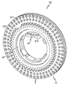
Figure 50 illustrates an embodiment of a lancet sheet for providing lancet structures.
51 is a detailed view of the lancet sheet of Fig.
52 is another detailed view of the lancet sheet of Fig.
Figure 53 shows the lancet sheet of Figure 50 with the outer ledge removed.
54 shows the removed outer register of Fig.
Figure 55 shows lancet structures released from the lancet sheet of Figure 50;
Figure 56 shows the released lancet structures of Figure 55 in the lancet compartments.
바람직한 실시예의 다음의 설명은 그 성질이 단순히 예시적이며, 결코 본 발명 또는 본 발명의 응용 또는 사용을 제한하고자 하는 것이 아니다.The following description of the preferred embodiments is merely exemplary in nature and is in no way intended to limit the invention or the application or use of the invention.
여기에 설명되는 실시예들은 일반적으로, 체액의 생물학적으로 중요한 성분들의 농도들을 획득 및 측정하기 위해 사용되는 헨드헬드 의료 진단 디바이스들에 관한 것이다. 특히, 헨드헬드 의료 진단 디바이스는 혈액 샘플을 획득하고 샘플의 혈당 레벨을 측정하기 위해 사용될 수 있다. 아래에서 설명되듯이, 의료 진단 디바이스는, 신체 부분에 찔린 상처를 발생시키기 위해 사용될 수 있는, 의료 진단 디바이스 내에 복수의 란셋 구조들을 가진 란셋 하우징 조립체를 포함할 수 있다. 란셋 구조들은 또한 모세관 작용을 사용하여 찔린 상처로부터 나오는 혈액을 취하고, 혈액을 시약 물질로 공급하기 위해 사용될 수 있다. 의료 진단 디바이스 내에 위치되는 측정 시스템은 획득한 혈액의 혈당 농도값을 결정하기 위해 사용될 수 있다.The embodiments described herein generally relate to hand held medical diagnostic devices used to acquire and measure concentrations of biologically important components of body fluids. In particular, a handheld medical diagnostic device can be used to acquire a blood sample and measure the blood glucose level of the sample. As described below, the medical diagnostic device may include a lancet housing assembly having a plurality of lancet structures in a medical diagnostic device, which may be used to create a puncture wound on the body part. The lancet structures can also be used to take blood from a punctured wound using capillary action and to supply blood to the reagent material. A measurement system located within the medical diagnostic device can be used to determine the blood glucose concentration value of the acquired blood.
도 1 을 참조하면, 투명 보호 렌즈 (13) 뒤에 디스플레이 디바이스 (12) 를 가진 휴대형 헨드헬드 의료 진단 디바이스 (10) 는, 내부의 전자 및 다른 기계식 컴포넌트들을 보호하는 요소 (14) 에 의해 일반적으로 표시되는 보호 인클로져를 포함한다. 보호 인클로져 (14) 는 형상이 다소 직사각형이지만, 원형 형상 등과 같은 임의의 다른 적합한 형상이 보호 인클로져를 위해 사용될 수 있다. 디스플레이 디바이스 (12) 는, 예를 들면 LCD 디스플레이 디바이스들, LED 디스플레이 디바이스들, OLED 디스플레이 디바이스들, 및 지금까지 개발될 수 있었던 다른 형태의 디스플레이 디바이스들과 같지만 그에 제한되지 않는 휴대형 헨드헬드 의료 진단 디바이스에 사용되는 임의의 적합한 디스플레이 디바이스일 수 있다. 또한, 디스플레이 디바이스 (12) 는 일련의 라이트들 및/또는 단일 통합된 디스플레이 스크린과는 대조적으로 다른 형태의 라이트 디바이스들을 포함하지만 그에 제한되지 않는 임의의 다른 다양한 표시기들일 수 있다. 도시된 실시예에서, 디스플레이 디바이스 (12) 는, 대전된 안료 입자들을 전장을 사용하여 재배치함으로써 가시적 이미지를 형성하는 정보 디스플레이일 수 있는 전기 영동 디스플레이와 같은 전자 종이 컴포넌트를 포함한다. 디스플레이 디바이스 (12) 는 그래픽, 텍스트, 및 다른 요소를 사용자에게 전자식으로 표시하기 위해 사용될 수 있다. 몇몇 실시예들에서, 디스플레이 디바이스 (12) 는, 스크린으로부터 요소를 선택하고, 그림을 그리며, 디바이스 (10) 상에서 수행되는 문자 인식 프로그램에 의해 텍스트를 입력시키기 위해, 사용자의 손가락의 팁, 및/또는 스타일러스 또는 다른 터칭 디바이스에 의해 사용되는 터치-스크린 사용자 인터페이스일 수 있다. 몇몇 실시예들에서, 의료 진단 디바이스 (10) 는 또한 예를 들면 음향 디바이스들, 진동 디바이스들 등과 같은 다른 형태의 출력 디바이스들을 포함할 수 있다.1, a portable hand held medical
의료 진단 디바이스 (10) 는 또한, 버튼 (18) 을 포함할 수 있는 사용자 인터페이스 (일반적으로 요소 (17) 라고 지칭됨) 를 포함한다. 하나 이상의 버튼이 또한 사용될 수 있다. 버튼 (18) 은 예를 들면 의료 진단 디바이스 (10) 의 메모리를 보고, 디바이스의 세팅을 조정하며, 테스트 결과들을 스크롤링하기 위해 오퍼레이터에 의해 사용될 수 있다. 버튼 (18) 은 버튼 (18) 을 누르는 것과 같이 수동으로 작동될 수 있다. 버튼 (18) 은 버튼 영역에 손가락의 팁을 위치시키고 및/또는 누름으로써 작동될 수 있는 터치 센서들 (예를 들면, 저항성 또는 용량성 터치 센서들, 표면 음향 파형 센서들, 적외선 LED, 광검출기들, 광전 변환기들 등) 을 포함할 수 있다. 이들 실시예에서, 버튼 (18) 은 이동되지 않을 수 있다. 대신에, 버튼 (18) 은 손가락을 놓을 곳을 식별하기 위해 시각적으로 표시될 수 있다. 터치 센서들을 사용하는 다른 실시예에서, 버튼 (18) 은 예를 들면 손가락 또는 터칭 디바이스를 터치 센서에 밀접한 근처로 가져오기 위해 이동할 수 있다. 몇몇 실시예들에서, 의료 진단 디바이스 (10) 는, 디스플레이 디바이스 (12) 에 제공되는 소프트웨어 구동 메뉴를 통해 네비게이팅하기 위해 사용자가 사용할 수 있는 OK 버튼 및/또는 조이스틱/트랙 볼과 같은 다른 버튼 또는 입력 형태들을 제공할 수 있다. 추가 버튼들은, 예를 들면 스크롤링의 방법으로서 의료 진단 디바이스 (10) 상의 특정 프로그램을 소환하고, 목록으로부터 항목을 선택하거나, 디바이스의 소프트웨어 디자이너가 버튼 또는 버튼들의 세트에 할당할 수 있는 임의의 기능을 제공하기 위해, 쇼트컷 버튼들로서 사용될 수 있다. 각각의 버튼 사이즈, 형상, 위치 및 기능은 의료 진단 디바이스 (10) 의 각각의 제조자 및 모델에 대해 변할 수 있다.The medical
란셋 포트 (20) 는 의료 진단 디바이스 (10) 의 바닥 (22) 에 위치된다. 란셋 포트 (20) 는, 란셋 구조가 보호 인클로져 (14) 로부터 외향으로 연장될 수 있는 개구를 제공한다. 란셋 구조는 환자의 피부 사이트에 절개 부분을 만들고 환자의 피부 사이트로부터 소정의 양의 체액을 발생시키기 위해, 란셋 포트 (20) 로부터 외향 연장될 수 있다. 일 실시예에서, 의료 진단 디바이스 (10) 는, 질병의 진단, 예방 및 치료를 위한 정보를 얻기 위해 혈액, 다른 체액들 및 조직들을 테스트하기 위해 사용되는 시험관 내 (in vitro) 진단 디바이스이다. 의료 진단 디바이스 (10) 는 당뇨병이 있는 사람을 위한 자가 테스팅 혈당 측정기일 수 있다. 일 실시예에서, 의료 진단 디바이스 (10) 는, 유체 샘플 내에서 시약과 포도당 사이의 화학적 반응의 몇몇 면모를 관찰함으로써 포도당 농도를 측정하는 헨드헬드 시약에 기초한 혈당 측정기이다. 시약은, 예측 가능한 방식으로 포도당과 반응하여 모니터가 샘플 내의 포도당의 농도를 결정할 수 있게 하는 화학적 화합물일 수 있다. 예를 들면, 의료 진단 디바이스 (10) 는, 일 실시예에서는 포도당과 시약 사이의 반응에 의해 발생되는 전압 또는 전류를 측정하고, 다른 실시예에서는 전기 저항을 측정하며, 또 다른 실시예에서는 시약의 색 변화를 측정하도록 구성될 수 있다.The
몇몇 실시예들에서, 의료 진단 디바이스 (10) 는, 접이식 하우징부들 (25, 27) 을 사용하여 작동되는 와인딩 조립체 (도시되지 않음) 를 보호 인클로져 (14) 가 포함하는 기계 구동식 디바이스이다. 도 1 은 초기 작동되지 않은 (uncocked) 위치에 있는 접이식 하우징부들 (25, 27) 을 도시한다. 아래에서 더 상세히 설명되듯이, 하우징부들 (25, 27) 은 란셋 작동기 조립체 (도시되지 않음) 를 감긴 트리거 가능한 구성으로 위치시키기 위해 서로에 대해 수동으로 이동될 수 있다. 란셋 작동기 조립체는, 환자의 피부 사이트에 절개를 하고, 환자의 피부 사이트로부터 운반될 수 있는 소정량의 체액을 발생시키기 위해, 란셋 구조를 란셋 포트 (20) 를 통해 구동하기 위해 사용될 수 있다. 몇몇 실시예들에서, 하우징부 (27) 는, 복수의 란셋 구조들을 포함하는 란셋 하우징 조립체 (도시되지 않음) 를 유지하기 위해 제거 가능한 도어 (65) 를 가진 카트리지 하우징 (29) 을 포함한다. 다른 실시예들에서, 도어 (65) 는 하우징부 (27) 에 힌지 결합될 수 있어, 도어는 란셋 하우징 조립체를 제거 또는 로딩하기 위해 카트리지 하우징 (29) 에 대한 액세스를 가능하게 하기 위해 하우징부 (27) 에 대해 회전될 수 있다. 란셋 하우징 조립체 내에 이용 가능한 사용되지 않은 란셋 구조들의 수에 대한 정보를 환자에게 제공하는 표시기 디바이스 (33) 가 구비될 수 있다. 이러한 실시예에서, 표시기 디바이스 (33) 는, 란셋 하우징 조립체가 카트리지 하우징 (29) 내에서 색인이 표시되어 있을 때 란셋 하우징 조립체에 제공된 숫자를 볼 수 있게 하는 제거 가능한 도어 (65) 의 윈도우 (35) 를 포함한다.In some embodiments, the medical
도 2 를 참조하면, 의료 진단 디바이스 (10) 의 단순화된 개략도는, 환자를 위해 향상된 안락 및 사용을 용이하게 하는 여러 가지 특징들을 포함한다. 일반적으로, 의료 진단 디바이스 (10) 는, 의료 진단 디바이스 (10) 에 사용하기 위해 복수의 란셋 구조들 (24) 을 수용하기 위해 사용되는 카트리지 또는 디스크 형태의 란셋 하우징 조립체 (30), 란셋 구조들 (24) 을 연장 및/또는 후퇴시키기 위한 란셋 작동기 조립체 (28), 및 란셋 구조 (24) 가 란셋 작동기 조립체 (28) 에 의해 연장 및/또는 후퇴되는 속도를 조절하기 위해 란셋 작동기 조립체 (28) 와 결합하는 속도 제어 기구 (36) 를 포함할 수 있다. 란셋 구조 (24) 를 연장시키기 전에 란셋 구조 (24) 의 관통 깊이를 조절할 수 있게 하는 깊이 조절 기구 (37) 가 또한 구비될 수 있다. 디스크 인덱싱 시스템 (77) 은, 하나의 사용된 란셋 구조로부터 다른 사용되지 않은 란셋 구조로 란셋 하우징 조립체 (30) 를 인덱싱하거나 회전시키기 위해 구비될 수 있다.Referring to FIG. 2, a simplified schematic of the medical
예를 들면, 일 실시예에서는 시약 내의 색 변화를 검출하기 위한 광학 디바이스 (34), 또는 다른 실시예에서는 시약의 전기 특성/성질의 변화를 측정하고자 하면 전기 접점들과 같은 다른 적합한 디바이스를 사용하여, 시료 (39) 에 공급되는 혈액 샘플의 포도당 농도를 측정하는 측정 시스템 (32) 이 구비될 수 있다. 시료 (39) 는 시약을 유지하고 포도당과 상술한 시약 사이의 반응을 주관하기 위해 사용될 수 있다. 일 실시예에서, 시료 (39) 및 광학 디바이스 (34) 는, 측정 시스템 (32) 이 샘플의 포도당의 농도를 결정하고 그 결과를 디스플레이 디바이스 (12) 를 사용하여 사용자에게 표시하기 위해, 포도당과 시약 사이의 반응이 전자식으로 판독될 수 있도록, 위치될 수 있다. 이들 실시예들은 건강 관리 전문가 및 환자가 병원, 진료소, 사무실 또는 환자의 집에서 신뢰성 있는 분산된 테스팅을 수행할 수 있게 한다.For example, in one embodiment, an
일 실시예에서, 시료 (39) 에 혈액 샘플이 공급된 후에, 시료 (39) 는 측정 시스템 (32) 에 의해 조명되어, 샘플과 시료 (39) 의 시약 사이의 화학적 반응으로 인한 임의의 색 변화는 광학 디바이스 (34), 예를 들면 광다이오드 검출기에 의해 검출된다. 광학 디바이스 (34) 로부터의 결과적인 검출 신호는 그러면 측정 시스템 (32) 의 프로세서 (31) 로 공급되고 프로세서 (31) 에 의해 프로세싱된다. 공급된 혈액 샘플의 특성(들) 및/또는 성질(들)을 결정하기 위해 수신된 검출 신호에 대한 프로세서 (31) 에 의한 프로세싱의 결과는 디스플레이 디바이스 (12) 상에 표시되고, 및/또는 디스플레이 디바이스 (12) 가 전자 종이에 기초한 디스플레이인 경우와 같이, 다음 측정 결과에 의해 갱신될 때까지 디바이스 (10) (또는 측정 시스템 (32)) 의 메모리 (33) 에 저장되거나 디스플레이 디바이스 (12) 에 의해 유지될 수 있다. 일 실시예에서, 사용자 인터페이스 (17) 는 사용자가, 메모리 (33) 내에 저장된 시험 결과를 선택하고 표시하며, 위에서 처음 부분에서 논의된 디바이스 기능 중 어느 하나를 수행하기 위해 프로세서 (31) 와 통신하기 위해 사용할 수 있다. 다른 실시예들에서, 프로세서 (31), 메모리 (33) 및 측정 시스템 (32) 은 디스플레이 컨트롤러 및/또는 디스플레이 드라이버, 클럭, 아날로그 디지털 변환기(들), 광(들), 전력 (전지) 관리 컨트롤러/기능들과 같은 다른 시스템 컴포넌트들 (도시되지 않음) 과 함께, 응용 특정 집적 칩 (ASIC) 로서 구비될 수 있거나, 또 다른 실시예들에서는 개별 (이산) 컴포넌트들로서 구비될 수 있거나, 또 다른 실시예들에서는 그들의 조합으로 구비될 수 있다. 그러한 컴포넌트들은 프로세서 (31) 에 전기적으로 연결되며, 그들은 모두 디바이스 (10) 의 실시예에서와 같이 제한된 용도 및 일회용 디바이스인, A/C 어댑터에 의해 재충전될 수 있거나 될 수 없는 전지와 같은, 휴대형 전원 공급장치 (도시되지 않음) 에 의해 구동된다. 적합한 의료 진단 디바이스의 다른 특징은, 2010년 12월 30일 출원되었고 발명의 명칭이 "헨드헬드 의료 진단 디바이스"인 공동 계류중이고 공동 소유된 미국 특허 출원 일련번호 12/981,677에 기술되어 있으며, 그 내용은 참고로써 본 명세서에 완전히 포함된다.In one embodiment, after the blood sample is supplied to the
도 3 을 참조하면, 몇몇 실시예들에서, 복수의 란셋 구조들은, 중앙 축 (42) 에 관해 방사 형상으로 배치되는 복수의 란셋 격실들 (40) 을 포함하는 디스크 (30) (디스크 (30) 의 일부만 설명을 위해 도 3 에 도시됨) 의 형태로 란셋 하우징 조립체 내에 수용된다. 디스크 (30) 는, 플라스틱들, 포일들, 금속들 등과 같은 임의의 하나 이상의 적합한 재료들로 형성되는 외부 보호 하우징 (도시되지 않음) 을 가질 수 있다. 소독 습기 배리어들을 가진 재료들은 란셋 격실들 (40) 에 보호된 환경들을 제공하기 위해 사용될 수 있다.Referring to Figure 3, in some embodiments, the plurality of lancet structures include a disc 30 (including disc 30) that includes a plurality of lancet compartments 40 disposed radially about a
도 4 를 참조하면, 몇몇 실시예들에서, 디스크 (30) 는 중심 허브 (48) 및 중심 허브 (48) 에 대해 회전하도록 구성되는 디스크 컴포넌트 (51) 에 의해 형성될 수 있다. 몇몇 실시예들에서, 디스크 컴포넌트 (51) 는 상부 디스크 부재 (41) 및 상부 디스크 부재 (41) 에 연결되는 하부 디스크 부재 (43) 를 포함한다. 상부 디스크 부재 (41) 와 하부 디스크 부재 (43) 사이에, 레이저 용접, 스냅 맞춤, 압입 끼워맞춤, 접착제, 패스너 등과 같은 어떠한 적합한 연결도 사용될 수 있다.Referring to Figure 4, in some embodiments, the
도 5 및 도 6 을 참조하면, 중심 허브 (48) 는 디스크 컴포넌트 (51) 에 대해 회전할 수 있도록 디스크 (30) 의 중앙 보어 (50) 내에 구비될 수 있다. 일 실시예에서, 중심 허브 (48) 는 디스크 (30) 의 중앙 보어 (50) 내에 정위치에 스냅 맞춤될 수 있도록 구비될 수 있다. 예를 들면, 중심 허브 (48) 는, 디스크 컴포넌트 (51) 의 저면 (73) 과 결합하는 후크형 돌출부들 형태의 고정 구조들 (47) 을 포함할 수 있다. 중심 허브 (48) 는, 도 5 에 도시된 스냅 맞춤 배열체를 통하거나 다른 실시예에서 저면 (73) 에 인접하는 중심 허브 (48) 의 나사가 지거나 성형된 단부 (도시되지 않음) 와 결합하는 너트 또는 클립 (도시되지 않음) 을 제공하는 패스너(들)을 통하는 것과 같이, 디스크 (30) 의 중앙 보어 (50) 내에 제거 가능하게 유지될 수 있도록 디스크 (30) 의 중앙 보어 (50) 내에 회전 가능하게 장착될 수 있지만, 다른 실시예에서는, 중심 허브 (48) 는 디스크 (30) 의 중앙 보어 (50) 내에 회전 가능하게 구비될 수도 있고, 또한 다른 실시예에서는 저면 (73) 에 대해 외향으로 플레어지는 중심 허브 (48) 의 변형된 자유 단부 (도시되지 않음) 를 제공하는 레이저 용접을 통하는 것과 같이 디스크 (30) 의 중앙 보어 (50) 내에 영구적으로 유지될 수도 있다. 중심 허브 (48) 는, 의료 진단 디바이스 (10) 의 디스크 격실 (52) 내로의 삽입을 위해 하나 이상의 배향들로만 디스크 (30) 의 자동 정렬을 가능하게 하는 비원형 또는 비정규 형상 (예를 들면, D자 형상) 의 키 또는 개구 (75) 를 가질 수 있다. 예를 들면, 도시된 실시예에서, D자형 키는 디스크 격실 (52) 내로의 삽입을 위해 하나의 배향으로만 디스크 (30) 의 자동 정렬을 가능하게 할 수 있다.Referring to Figures 5 and 6, the
상부 디스크 부재 (41) 는 상면 (49) 및 상면 (49) 과 반대인 저면 (56) 을 포함한다. 수치 표시 (53) (도 4) 는 사용되지 않은 란셋 구조들 (24) 및 사용된 란셋 구조들 (24) 의 수를 사용자에게 표시하기 위해 프린트, 성형, 에칭, 기계 가공 등에 의해 이루어질 수 있다. 수치 표시 (53) 는 제거 가능 도어 (65) (도 1) 의 윈도우 (35) 를 통해 볼 수 있다.The
특히 도 6 을 참조하면, 상부 디스크 부재 (41) 의 상면 (49) 은, 상부 디스크 부재 (41) 의 상면 (49) 으로부터 내향으로 연장되는 복수의 노치들 (55) 을 포함할 수 있다. 노치들 (55) 은 인접 노치들 (55) 로부터 각지게 이격되며, 상부 디스크 부재 (41) 의 중심으로부터 실질적으로 동일한 거리에 위치된다. 노치들 (55) 각각은 각각의 란셋 격실 (40) 과 결합되고, 중심 허브 (48) 에 대한 디스크 (30) 의 과도한 회전을 방지하기 위한 결합 구조를 제공할 수 있다.6, the
중심 허브 (48) 와 상부 디스크 부재 (41) 사이에 위치되는 스프링 컴포넌트 (81) 는, 상부 디스크 부재 (41) 의 회전 제한 구조 (예를 들면 노치들 (55)) 와 협동하는 회전 제한 구조 (54) 를 포함할 수 있다. 스프링 컴포넌트 (81) 는, 또한 중심 허브 (48) 에 대한 디스크 컴포넌트 (51) 의 회전을 용이하게 하는 환형 평평한 스프링일 수 있다. 스프링 컴포넌트 (81) 는, 디스크 컴포넌트 (51) 가 중심 허브 (48) 에 대해 회전할 때 노치들 (55) 에 의해 제거 가능하게 수용되도록 하는 사이즈를 가지고 배치되는 하향 돌출부 (61, 63) 를 각각 가지는 암 부재들 (57, 59) 을 포함할 수 있다. 돌출부들 (61, 63) 은 각각 암 부재들 (57) 의 굽힘부에 의해 형성될 수 있다. 암 부재들 (57, 59) 은, 돌출부 (61, 63) 가 1개의 노치 (55) 로부터 이동해 나오고, 상부 디스크 부재 (41) 를 중심 허브 (48) 에 대해 각도 관계로 잠금하기 위해 인접 노치 (55) 에 의해 수용될 수 있도록, 암 부재들 (57, 59) 이 탄성적으로 굽혀질 수 있게 하기 위해 다른 약간 탄성적으로 가요성인 재료의 스프링강으로 형성될 수 있다.The
하부 디스크 부재 (43) 는 상면 (79), 상면 (79) 과 반대인 저면 (73), 외향면 (64), 및 내향면 (66) 을 포함한다. 란셋 격실들 (40) 은 내향면 (66) 으로부터 외향면 (64) 으로 대체로 반경 방향으로 연장된다. 란셋 격실들 (40) 은 서로로부터 하부 디스크 부재 (43) 의 둘레에 대해 각진 거리로 동일하게 이격될 수 있다. 아래에서 더 상세히 설명되듯이, 각각의 란셋 격실 (40) 은, 각각의 란셋 격실 (40) 내의 개구 (68) 를 통하고 의료 진단 디바이스 (10) 의 란셋 포트 (20) 를 통해 연장될 수 있는 란셋 구조 (24) 를 포함할 수 있다. 도시된 실시예에서 치형부 (81) 를 가진 기어 프로파일의 형태인 디스크 인덱싱 구조 (77) 는 하부 디스크 부재 (43) 의 저면 (73) 으로부터 하향 연장된다. 디스크 인덱싱 구조 (77) 는 예를 들면 란셋 구조들 (24) 의 각각의 작동 후에 디스크 컴포넌트 (51) 를 중심 허브 (48) 에 대해 회전시키기 위해 사용될 수 있다. 스냅 링 (83) 은 상부 디스크 부재 (41) 와 하부 디스크 부재 (43) 를 연결하는 데에 사용될 수 있다. 포일 링들 (89, 91) 의 형태의 포일 스트립들은 개별 란셋 격실들 (40) 내로 또한 그로부터 외부로 안내되는 내부 개구 (68) 및 외부 개구 (93) 를 덮기 위해 사용될 수 있다.The
디스크 (30) 는 또한 데이터가 메모리에 저장된 메모리 칩 (97) 을 포함할 수 있다. 그러한 데이터는 디스크 (30) 내에 수용되는 디스크 컴포넌트를 위한 화학 데이터, 만기 일자 등을 포함할 수 있다. 메모리 칩 (97) 은, 카트리지 하우징 (29) 내에 위치되는 접점들 (101) 과 접촉되는 접점들 (99) 을 포함할 수 있다. 도 7 을 간략히 참조하면, 메모리 칩 (97) 은 중심 허브 (48) 에 위치되는 칩 수용 허브 (103) 내로 스냅 맞춤된다. 접점들 (99, 101) 은 데이터가 프로세서 (31) 에 의해 프로세싱될 수 있게 한다. 다른 실시예들에서, 디스크 (30) 는 옵션으로서의 RFID 택을 포함할 수 있고, 의료 진단 디바이스 (10) 는 RFID 판독기를 포함할 수 있다. 이들 실시예들에서, 의료 진단 디바이스 (10) 는 데이터를 RFID 택으로부터 다운로딩 받을 수 있다. 또한 알 수 있듯이, 디스크 (30) 는 또한, 윈도우 (105) 를 측정 시스템 (32) 과 정렬시키기 위해 디스크 (30) 의 인덱싱 이동을 제어하는 데에 사용하기 위한 측정 및 정렬부 (107) 를 만들기 위해 측정 시스템 (32) (도 2) 이 시약 물질에 액세스할 수 있게 하는 윈도우 (105) 를 더 포함한다. The
도 8 및 도 9 를 참조하면, 예시적 비어 있는 란셋 격실 (40) 및 사용되지 않은 란셋 구조 (24) 를 가진 란셋 격실 (40) 이 각각 도시되어 있다. 먼저 도 8 을 참조하면. 란셋 격실 (40) 이 하부 디스크 부재 (43) 의 격실 섹션 (62) 에 의해 부분적으로 형성된다. 상부 디스크 부재 (41) 는 도 8 및 도 9 에서 명확성을 위해 제거된다. 격실 섹션 (62) 은 외향면 (64) 및 내향면 (66) 을 포함한다. 개구 (68) 는, 의료 진단 디바이스 (10) (도 1) 의 바닥 (22) 에 위치되는 란셋 포트 (20) 와 정렬될 수 있는 외향면 (64) 에 위치된다. 측벽 (78, 80) 은 외향면 (64) 과 내향면 (66) 사이에서 연장된다. 틈새 플로어 (70) 는 란셋 격실 (40) 내의 외향면 (64) 에 있는 내벽 (71) 으로부터 내향면 (66) 으로 연장되고, 란셋 격실 (40) 의 최하부 플로어를 형성한다. 틈새 플로어 (70) 상에 및 란셋 격실 (40) 내에 위치되는 시약 물질 (72) 은 란셋 격실 (40) 의 내벽 (71) 에 인접한다. 시약 물질 (72) 은 몇 가지만 거론하면 전자 화학형 테스트 스트립들, 비색 또는 광학형 테스트 스트립들과 같은 테스트 스트립일 수 있다.Referring to Figures 8 and 9, there is shown an exemplary
드롭다운 (drop down) 슬롯들 (74, 76) 은 측벽 (78, 80) 에 위치되고, 격실 섹션 (62) 의 상면 (79) 으로부터 란셋 플로어 (84) 로 수직으로 연장된다. 다른 드롭다운 슬롯 (75) 은 내벽 (71) 에 위치되고, 개구 (68) 로부터 시약 물질 (72) 로 수직으로 연장된다. 란셋 플로어 (84) 는 시약 물질 (72) 로부터 내향면 (66) 을 향해 되돌려 틈새 플로어 (70) 를 따라, 또한 드롭다운 슬롯들 (74, 76) 내에서, 틈새 플로어 (70) 에 대해 상승된 관계로, 연장된다. 몇몇 실시예들에서, 란셋 플로어 (84) 는, 드롭다운 슬롯 (74, 76) 의 각각의 측벽 (78, 80) 을 따라 연장되고 서로 이격되어 한 쌍의 스트립들 (85, 87) 사이에 틈새 플로어 (70) 의 일부를 노출시키는 한 쌍의 스트립들 (85, 87) 에 의해 형성될 수 있다. 몇몇 실시예들에서, 란셋 플로어 (84) 및 틈새 플로어 (70) 는 동일한 플로어 구조의 일부일 수 있다. 란셋 플로어 (84) 는, 란셋 구조가 시약 물질 (72) 에 대해 하향 하강되어 란셋 플로어 (84) 에 기대어 안착될 때, 틈새 플로어 (70) 와 란셋 구조 (24) 사이에 틈새를 제공한다. 란셋 안내 레일들 (86, 88) 은 측벽들 (78, 80) 을 따라 연장되고 격실 섹션 (62) 의 상면 (79) 아래에서 수직으로 오목하게 된다. 몇몇 실시예들에서, 란셋 안내 레일들 (86, 88) 은, 드롭다운 슬롯 (75) 이 내벽 (71) 에서 란셋 안내 레일들 (86, 88) 과 교차하고 드롭다운 슬롯 (74, 76) 이 각각 측벽들 (78, 80) 에서 안내 레일들 (86, 88) 과 교차하는 상태에서, 드롭다운 슬롯들 (74, 76) 로부터 개구 (68) 로 란셋 플로어 (84) 및/또는 틈새 플로어 (70) 에 대해 실질적으로 평행하게 연장된다.Drop down
도 9 를 참조하면, 란셋 구조 (24) 를 가진 란셋 격실 (40) 이 도시되어 있다. 란셋 구조 (24) 는, 이러한 예시적 실시예에서, 피부 관통 단부 (90), 및 피부 관통 단부 (90) 에 인접하는 혈액 운반부 (92) 를 포함한다. 몇몇 실시예들에서, 혈액 운반부 (92) 는, 피부 관통 단부로부터 멀어져 혈액 운반부 (92) 로의 체액의 이동을 용이하게 하는 하나 이상의 모세관 구조들을 포함할 수 있다. 피부 관통 단부 (90) 는, 개구 (68) 를 따라 연장될 때, 소정 양의 혈액을 제공하기 위해, 피부 위치에서 환자의 피부를 관통하게 하는 형상 및 사이즈를 가진다. 혈액 운반부 (92) 는 피부 관통 단부 (90) 로부터 소정 양의 혈액을 수용할 수 있고, 소정 양의 혈액을 피부 위치로부터 떠나서 운반하기 위해 사용될 수 있다.Referring to FIG. 9, a
구동부재 연결 구조 (94) 는, 피부 관통 단부 (90) 에 대해 반대인 단부 (96) 에 위치된다. 이러한 실시예에서, 구동 부재 연결 구조 (94) 는, 구동 부재 (95) (예를 들면, 구동 후크의 형태임) 와 결합하기 위해 사용되는 후방 레지 (100) 를 가진 폐쇄된 개구 (98) 이다. 외향 연장 윙들 (102, 104) 의 형태의 레일 주행 구조는 구동 부재 연결 구조 (94) 와 혈액 운반부 (92) 사이에 위치된다. 윙들 (102, 104) 은, 란셋 구조 (24) 를 연장 및 후퇴시킬 때, 란셋 안내 레일들 (86, 88) 을 따라 주행하기 위해 폭 방향으로 외향 연장된다.The drive
도 10 을 참조하면, 란셋 격실 (40) 의 단면이, 상부 디스크 부재 (41) 가 하부 디스크 부재 (43) 에 연결되어 그들 사이에 란셋 격실 (40) 을 제공하는 조립된 구조로, 도시된다. 구동 부재 (95) 는 란셋 격실 (40) 내로 연장되고, 란셋 구조 (24) 의 구동 부재 연결 구조 (94) 와 해제 가능하게 결합된 상태로 도시되어 있다. 란셋 구조 (24) 의 피부 관통 단부 (90) 는, 윙 (윙 (102) 만 부분적으로 도시됨) 이 란셋 안내 레일들 (안내 레일 (86) 만 부분적으로 도시됨) 상에 놓이는 동안에, 개구 (68) 의 저면 (106) 에 놓이는 것으로 도시되어 있다.10, the cross section of the
편향 (biasing) 기구 (108) (예를 들면, 평평한 스프링) 는 란셋 플로어 (84) 를 향해 란셋 격실 (40) 내로 연장되며, 란셋 구조 (24) 의 표면 (110) 과 결합한다. 편향 기구 (108) 는 양쪽 단부들 (112, 114) 에서 상부 디스크 부재 (41) 의 천장 (116) 에 연결될 수 있다. 란셋 구조 (24) (도 9) 의 대응 오목부 (120) 와 결합되며 편향 기구 (108) 내에 형성되는 돌출부 (118) 가 구비될 수 있다. 또 다른 실시예에서, 란셋 구조 (24) 는 돌출부 (118) 를 포함할 수 있고, 편향 기구 (108) 는 오목부 (120) 를 포함할 수 있다. 대향하는 램프 (ramp) 구조들과 같은 임의의 다른 적합한 결합 배치가 사용될 수 있다. 이러한 결합 배치는 개구 (68) 를 통한 란셋 구조 (24) 의 피부 관통 단부 (90) 의 의도하지 않은 이동에 대한 저항을 추가할 수 있다.A biasing mechanism 108 (e.g., a flat spring) extends into the
도 11 을 참조하면, 란셋 구조 (24) 는 구동 부재 연결 구조 (94) 에 연결되는 구동 부재 (95) 를 사용하여 화살표 (122) 의 방향으로 개구 (68) 를 통해 연장될 수 있다. 도 10 및 도 11 에서 알 수 있듯이, 편향 기구 (108) 는, 단부들 (112, 114) 사이에서 편향 기구 (108) 의 길이를 따라 형성되는 슬롯 (124) 을 포함할 수 있다. 슬롯 (124) 은 구동 부재 (95) 의 후크부 (126) 를 수용하고 슬롯 (124) 을 통해 개구 (68) 를 향한 구동 부재 (95) 의 이동을 가능하게 하는 사이즈를 가질 수 있다. 몇몇 실시예들에서, 구동 부재 (95) 의 후크부 (126) 는, 란셋 구조 (24) 가 개구 (68) 를 향해 구동될 때 편향 기구 (108) 가 란셋 구조 (24) 와 접촉을 유지하도록, 슬롯 (124) 내에 수용된다. 란셋 구조 (24) 가 개구 (68) 를 향해 구동될 때 외향 연장되는 윙 (102, 104) 은 측벽들 (78, 80) 의 란셋 안내 레일들 (86, 88) 을 따라 주행한다.11, the
도 12 를 참조하면, 란셋 구조 (24) 는 구동 부재 (95) 를 사용하여 화살표 (128) 의 방향으로 개구 (68) 로부터 후퇴될 수 있다. 구동 부재 (95) 의 후크부 (126) 는, 란셋 구조 (24) 가 개구 (68) 로부터 멀어지는 방향으로 구동될 때 편향 기구 (108) 가 란셋 구조 (24) 와 접촉을 유지하도록, 슬롯 (124) 내에 수용될 수 있다. 도 12 에 도시되었듯이, 측벽들 (78, 80) 의 란셋 안내 레일들 (86, 88) 을 따라 주행하는 외향 연장 윙들 (102, 104) 이 일단 드롭다운 슬롯들 (74, 76) 과 정렬되고, 피부 관통 단부 (90) 가 드롭다운 슬롯 (75) 과 정렬되거나 드롭다운 슬롯 (75) 을 넘어 이동되면, 편향 기구 (108) 는 란셋 구조 (24) 를 후퇴 방향 (128) 에 대해 실질적으로 횡 방향으로 란셋 플로어 (84) 및 시약 물질 (72) 을 향해 강제한다. 따라서, 편향 기구 (108) 는, 란셋 구조 (24) 가 구동 부재 (95) 에 의해 후퇴될 때, 란셋 구조 (24) 를 시약 물질 (72) 로 자동 공급하기 위해 사용될 수 있다.12, the
도 13 을 참조하면, 란셋 구조 (24) 는 완전히 후퇴되고 시약 물질 (72) 을 향한다. 이러한 위치에서, 란셋 구조 (24) 의 피부 관통 단부 (90) 와 혈액 운반부 (92) 는, 혈액이 시약 물질 (72) 로 이송될 수 있도록, 개구 (68) 로부터 이격되고 (즉, 개구 (68) 와의 정렬로부터 벗어남) 시약 물질 (72) 과 접촉한다. 란셋 구조 (24) 를 시약 물질 (72) 로 공급하는 것에 더하여, 개구 (68) 와의 정렬을 벗어나는 피부 관통 단부 (90) 의 이격 배치는, 란셋 구조 (24) 를 더 이상 결합 및 연장할 수 없는 구동 부재 (95) 에 의한 개구 (68) 를 통한 피부 관통 단부 (90) 의 의도하지 않은 연장을 방지할 수 있다. 특히, 도시된 실시예에서, 구동 부재 (95) 가 사용된 란셋 구조 (24) 를 포함하는 란셋 격실 (40) 의 개구 (68) 를 향해 일단 다시 이동하여야 하면, 구동 부재 (95) 는 이격 배치로 인해 란셋 구조 (24) 를 넘어 통과하여, 란셋 구조 (24) 의 구동 부재 연결 구조 (94) 를 구동 부재 (95) 와의 정렬이 벗어나게 위치시킨다. 따라서, 혈액을 란셋 구조 (24) 의 혈액 운반부 (92) 로부터 시약 물질 (72) 로 이송한 후에 란셋 구조 (24) 를 이격 배치에 있게 하는 편향 기구 (108) 는 편리한 안전-고장을 제공한다.Referring to FIG. 13, the
도 14 를 참조하면, 후크부 (126) 를 포함하는 구동 부재 (95) 는, 구동 부재 (95) 를 연장 및 후퇴시키기 위해 사용되는 란셋 작동기 조립체 (28) 에 작동 가능하게 연결된다. 구동 부재 (95) 는 후크 암 (130) 에 연결된다. 후크 암 (130) 은, 구동 부재 (95) 를 연장 및 후퇴 위치들을 향해 정확하게 안내하기 위해 사용되는 한 쌍의 안내 레일들 (132, 134) 을 따라 미끄러질 수 있다. 안내 레일들 (132, 134) 은 앵커 (136) 에 의해 하우징부 (27) 에 고정 연결된다. 후크 암 (130) 은 조절 가능 링키지 (140) 에 의해 종동 암 (138) 에 연결된다. 종동 암 (138) 은 시계장치 스프링 구동 조립체 (144) 에 의해 양쪽 방향 (화살표 142로 표시됨) 으로 구동되고, 그것은 후크 암 (130) 및 구동 부재 (95) 를 그들의 연장 및 후퇴 위치들 사이에서 이동시킨다.14, a
또한, 도 15 를 참조하면, 랙 부재 (146) 는 기어 감기 조립체 (150) 를 통해 시계 장치 스프링 구동 조립체 (144) 를 감기 위해 사용된다. 랙 부재 (146) 는, 구동 기어 (168) 를 회전시키기 위해 구동 기어 (168) 와 결합할 수 있는 (예를 들면, 시계 방향과 같이 한 방향으로만 회전할 때) 암들 (164, 166) 을 가진 캠 기어 (162) 의 치형부 (160) (도 14) 와 결합되며 랙 부재 (146) 의 길이를 따라 연장되는 치형부 (154) 를 포함한다. 15, the
랙 부재 (146) 는 슬라이딩 가능 캠 조립체 (170) 에 연결된다 (예를 들면, 패스너들과 같은 임의의 적합한 연결을 사용하거나, 성형 등에 의해 랙 부재 (146) 와 슬라이딩 가능 캠 조립체 (170) 를 1개의 일체식 컴포넌트로서 형성함으로써). 슬라이딩 가능 캠 조립체 (170) 는, 접이식 부분 (27) 에 대한 접이식 하우징부 (25) 의 이동이 랙 부재 (146) 를 기어 감기 조립체 (150) 에 대해 이동시키도록, 접이식 하우징부 (25) 에 연결된다. 도 15 및 아래의 설명으로부터 알 수 있듯이, 화살표 176의 방향으로의 랙 부재 (146) 의 이동은 캠 기어 (162) 가 시계 방향으로 회전하게 한다. 시계 방향으로 회전하면, 캠 기어 (162) 는 구동 기어 (168) 와 결합될 수 없고, 구동 기어 (168) 에 대해 회전할 수 있다. 따라서, 접이식 부분 (27) 을 화살표 176 의 방향으로 외향으로 이동시키면, 시계 장치 스프링 구동 조립체 (144) 를 복귀 행정 동안에 감거나 준비시키는 예비부하 또는 예비 준비된 위치에 랙 부재 (146) 가 위치된다. 화살표 176 에 대해 반대인 방향으로 랙 부재 (146) 를 이동시키면, 캠 기어 (162) 는 반시계 방향으로 회전된다. 반시계 방향으로 회전하면, 캠 기어 (162) 는 구동 기어 (168) 와 결합되며, 그것은 아래에서 더 상세히 설명하듯이 인접 시계 장치 스프링 구동 조립체 (144) 를 감는다.The
도 16 은 분리된 상태의 예시적 시계 장치 스프링 구동 조립체 (144) 의 분해도이다. 시계 장치 스프링 구동 조립체 (144) 는 스프링 휠 (180), 비틀림 스프링 (182), 및 롤러 휠 (186) 을 포함한다. 스프링 (182) 은 스프링 휠 (180) 을 롤러 휠 (186) 에 연결한다. 내부 단부 (188) 에서, 스프링 (182) 은 롤러 휠 (186) 에 연결되고, 외부 단부 (190) 에서, 스프링 (182) 은 스프링 휠 (180) 에 연결된다. 피봇 액슬 주위로의 롤러 휠 (186) 에 대한 스프링 휠 (180) 의 회전은 스프링 (182) 이 감기게 하여, 스프링 (182) 내의 저장 에너지를 증가시킨다.16 is an exploded view of an exemplary timepiece
롤러 휠 (186) 은, 롤러 휠 (186) 의 면 (198) 에 구비되는 홈 (196) 을 포함하는 면 캠부 (192) 를 포함한다. 홈 (196) 은, 롤러 휠 (186) 이 회전할 때 종동 암 (138) 이 연장 및 후퇴 위치들 사이에서 고정 길이만큼 이동되도록, 종동 암 (138) (도 14) 이 뒤따르는 트랙을 제공한다. 종동 핀 (200) 은 롤러 휠 (186) 의 반대 면 (202) 에 구비된다. 롤러 휠 (186) 의 회전 (및, 따라서 종동 암의 이동) 은 종동 핀 (200) 과 슬라이딩 가능 캠 조립체 (170) 의 캠 트랙부 사이의 상호작용을 통해 제어된다.The
도 17 을 참조하면, 슬라이딩 가능 캠 조립체 (170) 는 분리된 상태로 도시되어 있고, 단부 (208) 로부터 외향으로 또한 랙 부재 (146) 에 대해 대체로 평행하게 연장되는 트랙부 (220) 를 포함한다. 트랙부 (220) 는, 일 단부 (226, 228) 에서 단부 (208) 에 외팔보식으로 연결되고 결합된 자유 단부 (330) 로 외향 연장되는 한 쌍의 트랙 지지 부재들 (222, 224) 에 의해 형성된다. 슬롯 (332) 은, 슬라이딩 가능 캠 조립체 (170) 가 피봇 액슬 (187) 에 의해 슬라이딩할 수 있도록, 시계 장치 스프링 구동 조립체 (144) 의 피봇 액슬 (187) (도 14) 를 수용하는 사이즈를 가지는 트랙부 (220) 의 길이를 따라 연장된다. 각각의 트랙 지지 부재들 (222, 224) 의 상면들 (229, 231) 로부터 상향 연장되는 각각의 세장형 안내 트랙 부재 (225, 227) 는 트랙 지지 부재들 (222, 224) 각각에 의해 지지된다. 안내 트랙 부재들 (225, 227) 은 롤러 휠 (186) 의 회전을 제어함으로써 (즉, 가능하게 하고 불가능하게 함) 시계 장치 스프링 구동 조립체 (144) 의 감기 및 해제를 제어하기 위해 사용된다.17, the
도 18 내지 도 22 는 시계 장치 스프링 구동 조립체 (144), 기어 감기 조립체 (150), 랙 부재 (146) 및 슬라이딩 가능 캠 조립체 (170) 를 사용하는 준비 및 발사 시퀀스를 도시하고 있다. 롤러 휠 (186) 은 약간 투명하게 도시되어, 종동 핀 (200) 이 트랙부 (220) 및 안내 트랙 부재들 (225, 227) 과 상호작용할 때의 종동 핀 (200) 을 볼 수 있다. 도 18 은, 종동 핀 (200) 이 스프링 (182) 에 의해 안내 트랙 부재 (225) 의 벽부 (334) 에 대해 시계 방향으로 편향된 상태에서, 시작 위치에 있는 롤러 휠 (186) 과 슬라이딩 가능 캠 조립체 (170) 를 도시하고 있다. 이러한 위치에서, 슬라이딩 가능 캠 조립체 (170) 는, 하우징부 (25) 와 슬라이딩 가능 캠 조립체 (170) 의 연결을 통해, 또한 시계 장치 스프링 구동 조립체 (144) 가 하우징부 (27) 에 회전 가능하게 연결됨으로 인해, 시계 장치 스프링 구동 조립체 (144) 에 대해 화살표 336 의 방향으로 당겨질 수 있다. 도 19 는, 종동 핀 (200) 이 안내 트랙 부재 (227) 의 벽부 (338) 에 대해 편향된 상태에서, 완전히 예비 준비된 위치에 있는 슬라이딩 가능 캠 조립체 (170) 를 도시하고 있다. 상술한 바와 같이, 화살표 336의 방향으로의 슬라이딩 가능 캠 조립체 (170) 및 슬라이딩 가능 캠 조립체 (170) 에 연결된 랙 부재 (146) (도 14) 의 이동은 캠 기어 (162) 를 시계 방향으로 회전시킨다. 시계 방향으로 회전되면, 캠 기어 (162) 는 구동 기어 (168) 와 결합되지 않고, 스프링 (182) 을 감지 않으면서 구동 기어 (168) 에 대해 회전할 수 있다. 그러나, 스프링 (182) 은, 완전 예비 준비된 위치에서, 종동 핀 (200) 이 안내 트랙 부재 (225) 에 대해 안내 트랙 부재 (225) 의 에지 (340) 를 넘어 안내 트랙 부재 (227) 의 벽부 (338) 로 이동하도록, 소정 양만큼 예비 부하가 걸린다.18-22 illustrate the preparation and firing sequence using the watch mechanism
이제 도 20 을 참조하면, 슬라이딩 가능 캠 조립체 (170) 는, 종동 핀이 안내 트랙 부재들 (225, 227) 사이에 있는 상태에서 완전히 예비 준비된 위치에 일단 위치되면, 감긴 트리거 가능한 위치 (또는 준비된 위치) 를 향해 화살표 342 의 방향으로 밀어질 수 있다. 슬라이딩 가능 캠 조립체 (170) 가 화살표 342 의 방향으로 밀리면, 화살표 342 의 방향으로의 슬라이딩 가능 캠 조립체 (170) 및 슬라이딩 가능 캠 조립체 (170) 에 연결된 랙 부재 (146) 의 이동 (도 14) 은 캠 기어 (162) 를 반시계 방향으로 회전시킨다. 반시계 방향으로 회전되면, 캠 기어 (162) 는 구동 기어 (168) 와 결합되어 스프링 휠 (180) 을 회전시키고 스프링 (182) 을 감는다 (도 14). 안내 트랙 부재 (227) 는 롤러 휠 (186) 의 회전을 방지하고, 그것은 스프링 휠 (180) 이 회전할 때 스프링 (182) 이 롤러 휠 (186) 에 대해 감길 수 있게 한다.Referring now to FIG. 20, the
구동 기어 (168) 가 반시계 방향으로 회전될 때, 기어 결합 핀 (346) 은 제네바 휠 기어 (350) 의 슬롯 (348) 을 향해 이동한다. 제네바 휠 기어 (350) 는, 기어 결합 핀 (346) 이 슬롯 (348) 을 통해 이동할 때 구동 기어 (168) 의 연속 회전을 간헐적 회전 이동으로 변환하는 기어 기구이다. 제네바 휠 기어 (350) 는 디스크 구동 기어 (380) 와 결합되며, 디스크 구동 기어 (380) 는 디스크 인덱싱 구조 (66) 의 치형부 (81) 와 결합된다 (도 7). 제네바 휠 기어 (350) 의 간헐적 회전 이동은 인접 란셋 격실 (40) 을 란셋 포트 (20) 와 일직선이 되게 하기 위해 디스크 컴포넌트 (51) 의 인덱싱 이동을 발생시킨다.The
종동 핀 (200) 은 초기 멈춤부 (344) 에 도달할 때까지 안내 트랙 부재 (227) 를 따라 이동한다. 종동 핀 (200) 은 그러면 스프링 (182) 에 의해 롤러 휠 (186) 에 제공되는 편향력으로 인해 초기 멈춤부 (344) 로 회전할 수 있다. 종동 핀 (200) 이 이러한 위치에 있을 때, 슬라이딩 가능 캠 조립체 (170) 는 준비된 안전-준비 위치에 있다. 작동 이동은 슬라이딩 가능 캠 조립체 (170) 가 화살표 336 의 당김 방향으로 비교적 짧은 거리 이동하게 하고, 그것은 종동 핀 (200) 이 안내 트랙 부재 (227) 의 에지 (352) 를 지나 최종 멈춤부 (345) 로, 또한 도 21 에 도시된 감긴 트리거 가능 위치로 이동하게 한다.The
종동 핀 (200) 이 일단 도 21 의 감긴 트리거 가능 위치에 있으면, 의료 진단 디바이스 (10) 는 란셋 포트 (20) 를 통해 란셋 구조 (24) 를 발사할 준비가 된다. 의료 진단 디바이스 (10) 를 트리거하는 것은 손가락 또는 다른 신체 부분을 란셋 포트 (20) 에 위치시키고, 하우징부 (25) 를 하우징부 (27) 를 향해 누름으로써 달성될 수 있다. 도 22 를 참조하면, 롤러 휠 (186) 은, 종동 핀 (200) 이 안내 트랙 부재 (227) 에 의해 제공되는 해제 지점 (354) 을 넘어 일단 이동하면, 스프링 (182) 에 의해 제공되는 편향으로 인해 회전한다. 롤러 휠 (186) 의 회전은 란셋 구조 (24) 가 란셋 포트 (20) 로부터 외향으로 연장되고 란셋 포트 (20) 로 되돌려 후퇴되게 한다.The medical
몇몇 실시예들에서, 설명을 목적으로 하는 란셋 구조 (24) 의 시간에 따른 속도의 프로파일이 도시된다. 알 수 있듯이, 부분 A는 구동 부재와 란셋 구조 (24) 의 결합을 도시하고 있고, 부분 B는 피부 관통 단부 (90) 가 피부 사이트에 접근 및 관통할 때의 란셋 구조 (24) 의 비교적 빠른 가속을 도시하고 있다. 부분 C는 피부 관통 단부가 피부 사이트를 나올 때의 란셋 구조 (24) 의 비교적 느린 가속을 도시하고 있다. 그러한 느린 가속은 피부 사이트로부터 유체 샘플 (예를 들면, 100 nL) 의 흡입을 가능하게 할 수 있다. 부분 D는 란셋 구조 (24) 의 후퇴 동안에 부분 B 뒤의 높은 가속을 도시하고 있다. 몇몇 실시예들에서, 후퇴 위상 동안의 시간에 대한 연장 위상 동안의 시간의 비는 적어도 약 1:25 이다. 감속은 예를 들면 래칫 기구 (368) 상의 스프링 편향을 증가 또는 감소시킴으로써 및/또는 기어비를 변경함으로써 조절될 수 있다.In some embodiments, a profile of the velocity over time of the
도 14 및 도 23 을 다시 참조하면, 속도 제어 기구 (36) 는 기어박스일 수 있고, 하우징 (356), 기어 (364, 366), 및 래칫 기구 (368) 를 포함한다. 기어 (364) 는 결합 기어이고, 롤러 휠 (186) 이 회전할 때 시계 장치 스프링 구동 조립체 (144) 와 결합된다. 일 실시예에서, 롤러 휠 (186) 은, 롤러 휠 (186) 의 둘레에서 특정한 위치에서 롤러 휠 (186) 의 직경을 증가시키는 편심 링 부재 (372) (예를 들면 고무 또는 플라스틱으로 형성됨) 를 포함한다. 란셋 구조 (24) 의 복귀 행정 동안에 롤러 휠 (186) 이 회전할 때, 편심 링 부재 (372) 는 기어 (364) 와 마찰식으로 결합하여 기어 (364) 를 회전시키고 롤러 휠 (186) 을 느리게 한다. 기어 (364) 가 회전할 때, 기어 (366) 가 회전하게 된다. 래칫 기구 (368) 는 기어 (366) 의 외부 치형부 (370) 와 결합하여, 속도 제어 기구 (36) 가 회전하는 속도를 느리게 하거나 제어한다.14 and 23, the
도 24 를 참조하면, 설명을 목적으로 하는 란셋 구조 (24) 의 시간에 따른 속도의 프로파일이 도시되어 있다. 알 수 있듯이, 부분 A는 피부 관통 단부 (90) 가 피부 사이트에 접근 및 관통할 때의 란셋 구조 (24) 의 비교적 빠른 가속을 도시하고 있다. 부분 B는 피부 관통 단부가 피부 사이트를 나올 때의 란셋 구조 (24) 의 비교적 느린 감속을 도시하고 있다. 몇몇 실시예들에서, 후퇴 위상 동안의 시간에 대한 연장 위상 동안의 시간의 비는 적어도 약 1:25 이다. 감속은 예를 들면 래칫 기구 (368) 상의 스프링 편향을 증가 또는 감소시킴으로써 및/또는 기어비를 변경함으로써 조절될 수 있다.Referring to Fig. 24, the velocity profile of the
도 14 를 다시 참조하면, 상술한 바와 같이, 의료 진단 디바이스 (10) 는 깊이 조절 기구 (37) 를 더 포함할 수 있다. 깊이 조절 기구 (37) 는, 피봇 위치 (P1) 에서 조절 가능 링키지 (140) 에 조절 가능하게 연결되는 섬휠 (thumb wheel)(355) 을 포함할 수 있다. 섬휠 (355) 의 회전은 조절 가능 링키지 (140) 의 단부 (357) 의 이동을 일으키고, 그것은 조절 가능 링키지가 피봇 위치 (P2) 주위로 피봇하게 하며 구동 부재 (95) 의 후크부 (126) 의 시작 위치를 조절한다. 란셋 구조 (24) 를 향한 구동 부재 (95) 의 후크부 (126) 의 이동은 종동 암 (138) 과 롤러 휠 (186) 의 고정된 행정 길이로 인해 란셋 구조 (24) 의 피부 관통 단부 (90) 의 관통 깊이를 증가시킬 수 있다. 란셋 포트 (20) 로부터 멀어지는 방향으로의 구동 부재 (95) 의 후크부 (126) 의 이동은 란셋 구조 (24) 의 피부 관통 단부 (90) 의 관통 깊이를 감소시킬 수 있다. 일 예시적 실시예로서, 관통 깊이 (예를 들면, 피부 관통 단부 (90) 가 란셋 포트 (20) 를 넘어 연장되는 거리) 는 약 0.8 mm로부터 약 2.3 mm로 조절될 수 있다. 또한, 종동 암 (138) 은 구동 부재 (95) 를 연장 및 후퇴시키기 위해 조절 가능 링키지 (140) (예를 들면, 슬롯 (381) 에서) 에 연결되기 때문에, 조절 가능 링키지 (140) 는 종동 암 (138) 의 이동에 대한 구동 부재 (95) 의 이동을 증폭시키는 작용을 할 수 있다. 몇몇 실시예들에서, 조절 가능 링키지 (140) 는 종동 암 (138) 에 대한 구동 부재 (95) 의 1.8:1의 비의 배율을 제공한다.Referring again to Fig. 14, as described above, the medical
이제 도 25 를 참조하면, 란셋 하우징 조립체 (400) (예를 들면 디스크 형태임) 의 다른 실시예는 란셋 격실 (405) 을 한정하는 상부 디스크 부재 (402) 및 하부 디스크 부재 (404) 를 포함한다. 란셋 구조 (406) 는 피부 관통 단부 (408), 혈액 운반부 (410), 및 구동 부재 (414) 와 결합하기 위한 결합 구조 (412) 를 포함한다. 상술한 실시예와 유사하게, 란셋 구조 (406) 는, 란셋 격실 (405) 의 측벽 (420) 을 따라 연장되는 측부 레일 (418) 을 따라 주행할 수 있는 측 방향으로 연장되는 윙 (416) 을 포함한다. 이러한 실시예에서, 측부 레일 (418) 은, 란셋 구조 (406) 가 란셋 플로어 (424) 를 향해 이동하고 (즉, 스냅 다운되고), 구동 부재를 해제하며, 피부 관통 단부 (408) 가 시약 물질 (426) 과 접촉하게 하는 계단부 (422) 를 포함한다. 도시된 실시예에서, 계단부 (422) 는 수직에 대해 실질적으로 평행하지만 (즉, 측부 레일 (418) 에 대해 직각임), 계단부는 수직에 대해 다른 각도일 수 있다.25, another embodiment of a lancet housing assembly 400 (e.g., in the form of a disk) includes an
도 26 을 참조하면, 란셋 하우징 조립체 (430) 의 다른 실시예는, 란셋 구조 (432) 의 피부 관통 단부 (434) 를 시약 물질 (436) 과 접촉시키기 위해 란셋 구조 (432) 의 곡률을 사용할 수 있다. 이러한 실시예에서, 란셋 구조 (432) 는, 란셋 격실 (444) 의 측벽 (442) 을 따라 연장되는 구부러진 측부 레일 (440) 을 따라 주행할 수 있는 측 방향으로 연장되는 윙 (438) 을 포함한다. 피부 관통 단부 (434) 가 개구 (446) 에 의해 당겨질 때, 란셋 구조 (432) 의 곡률은 피부 관통 단부 (434) 가 시약 물질 (436) 과 접촉하게 한다.Another embodiment of the
도 27 내지 도 29 를 참조하면, 란셋 구조 (450) 의 이동은 측 방향 성분 (즉, 인접 란셋 격실을 향한 각진 이동) 을 가질 수 있다. 란셋 하우징 조립체 (452) (예를 들면, 디스크의 형태임) 는 란셋 격실 (458) 을 한정하는 상부 디스크 부재 (454) 및 하부 디스크 부재 (456) 를 포함한다. 란셋 구조 (450) 는 피부 관통 단부 (462), 혈액 운반부 (464), 및 구동 부재와 결합하기 위한 결합 구조 (466) 를 포함한다. 상술한 실시예와 유사하게, 란셋 구조 (450) 는, 란셋 격실 (458) 의 측벽 (472) 을 따라 연장되는 측부 레일 (470) 을 따라 주행할 수 있는 측 방향으로 연장되는 윙 (468) 을 포함한다. 이러한 실시예에서, 개구 (474) 는, 란셋 구조 (450) 를 시약 물질 (478) 과 접촉시키기 위해, 피부 관통 단부 (462) 를 인접 란셋 격실을 향해 측 방향으로 강제하는 수평 벽 컴포넌트 (476) 를 포함한다. 27-29, movement of the
도 30 내지 도 42 는, 란셋 격실 (505) 을 한정하는 상부 디스크 부재 (502) 및 하부 디스크 부재 (504) 를 포함하는 란셋 하우징 조립체 (500) 의 다른 실시예를 도시하고 있다. 란셋 구조 (506) 는 피부 관통 단부 (508), 혈액 운반부 (510), 및 구동 부재 (514) 와 결합하기 위한 결합 구조 (512) 를 포함한다. 먼저 도 30 을 참조하면, 고정 구조 (516) 는 란셋 구조 (506) 를 란셋 격실 (505) 내에 고정하기 위해 구비된다. 고정 구조 (516) 는, 란셋 구조 (506) 와 구동 부재 (514) 의 결합 동안에 란셋 구조 (506) 의 길이 방향 변위 없이 어떤 힘이 란셋 구조 (506) 에 위치될 수 있게 한다. 그러나, 고정 구조 (516) 는 사전 선택된 임계 힘 위의 힘에 반응하여 란셋 구조 (506) 의 길이 방향 변위를 가능하게 할 수 있다.30-42 illustrate another embodiment of a
고정 구조 (516) 는, 란셋 구조 (506) 의 연장된 축으로부터 외향 연장되는 스프링 부재 (518, 520) 를 포함할 수 있다. 스프링 부재들 (518, 520) 은 각각, 스프링 부재들 (518, 520) 을 수용하는 사이즈를 가지는 각각의 노치 (522, 524) 에 수용될 수 있다. 고정 구조 (516) 의 잠금 강도는 스프링 부재들 (518, 520) 의 스프링 강도 및 노치들 (522, 524) 의 출구 각도를 사용하여 선택될 수 있다. 이러한 실시예에서, 노치들 (522, 524) 의 출구 각도들은 약 90도보다 작다.The anchoring
도 31 은, 란셋 구조 (506) 가 고정 구조 (516) 와 결합된 상태에서, 구동 부재 (514) 를 포함하는 시작 위치를 도시하고 있다. 란셋 구조 (506) 를 시약 물질 (532) 로부터 이격시키기 위해 지지 구조들 (530) 상에 놓이는 윙 구조들 (526, 528) 이 구비될 수 있다 (도 30). 구동 부재 (514) 는 란셋 격실 (505) 내로 삽입되고, 상술한 것과 유사한 방식으로 전방으로 밀려질 수 있다. 몇몇 실시예들에서, 구동 부재 (514) 는, 역시 도 32 에 도시된 상향 스프링 힘 (F)(예를 들면, 스프링을 사용함) 을 받는다.31 shows the starting position including the driving
도 32 에서, 구동 부재 (514) 는, 둥근 외주를 가지며 후크부 (536) 로부터 상향 연장되는 안내 돌출부 (534) 를 포함한다. 안내 돌출부 (534) 는, 란셋 구조 (506) 의 결합 구조 (540) 와 결합하기 위한 후크부 (536) 를 위치시키기 위해 후크부 (536) 를 하향으로 강제하기 위해 하향 연장되는 캠 표면 (538) 과 결합할 수 있다. 도 33 을 참조하면, 안내 돌출부 (534) 가 캠 표면 (538) 을 지나 이동할 때, 후크부 (536) 는 편향 (F) 으로 인해 상승되며, 란셋 구조 (506) 의 결합 구조 (540) 와 결합된다.32, the driving
도 34 에서, 스프링 부재들 (518, 520) (도 30) 은 노치들 (522, 524) 로부터 자유로울 수 있으며, 도 35 에서, 랜딩 부재 (542) 는 후크부 (536) 의 상향 이동을 제한하기 위해 캠 표면 (538) 과 결합할 수 있다. 도 36 및 도 37 에서, 절개는, 피부 관통 단부 (508) 를 개구 (544) 를 통해 이동시킴으로써, 다음에 상술한 것과 유사한 방식으로 감속된 복귀 이동에 의해 이루어질 수 있다.In Figure 34, the
도 38 을 참조하면, 란셋 구조 (506) 의 복귀 이동의 종료시점에, 편향력 (F) 은 란셋 구조 (506) 에 작용하여 란셋 구조 (506) 를 인장시킨다. 윙 구조들 (526, 528)(도 30) 이 지지 구조들 (530) 에 놓임으로써, 갭이 도 38 에 도시된 바와 같이 란셋 구조 (506) 와 시약 물질 (532) 사이에 남는다. 도 39 를 참조하면, 구동 부재 (514) 의 추가 복귀 이동에 의해, 윙 구조들 (526, 528)(도 30) 은 지지 구조들 (530) 과 분리되고, 피부 관통 단부 (508) 는 시약 물질 (532) 과 접촉한다. 편향력 (F) 은, 액체 접촉이 일어나도록, 피부 관통 단부 (508) 와 시약 물질 (532) 사이의 접촉을 용이하게 한다. 구동 부재 (514) 의 추가 복귀 시에, 안내 돌출부 (534) 는, 도 39 에 도시된 바와 같이 란셋 구조 (506) 를 분리하기 위해, 캠 표면 (538) 과 결합하여 후크부 (536) 를 강제한다. 도 40 을 참조하면, 리브들 (544) 은 란셋 구조 (506) 내의 스프링 인장을 유지하기 위해 구비될 수 있다.38, at the end of the return movement of the
도 41 내지 도 48 은, 란셋 격실 (605) 을 한정하는 상부 디스크 부재 (602) 및 하부 디스크 부재 (604) 를 포함하는 란셋 하우징 조립체 (600) 의 다른 실시예를 도시하고 있다. 란셋 구조 (606) 는 피부 관통 단부 (608), 혈액 운반부 (610), 및 구동 부재 (614) 와 결합하기 위한 결합 구조 (612) 를 포함한다. 먼저 도 41 을 참조하면, 란셋 구조 (606) 및 구동 부재 (614) 의 초기 위치가 도시되어 있다. 이러한 실시예에서, 란셋 구조 (606) 는, 부분 (618) 에서 상향 연장되고 부분 (620) 에서 길이 방향으로 연장되는 외향 연장되는 스프링 핑거 (616) 를 포함한다. 굽힘부 (622) 는 상향 연장부 (618) 와 길이 방향 연장부 (620) 를 연결한다. 길이 방향 연장부 (620) 는, 노치 (626) 내에 수용되어 란셋 구조 (606) 를 란셋 격실 (605) 내에 고정하기 위한 고정 구조를 제공하는 봉우리형 부분 (hump-shaped portion; 624) 을 포함한다. 41-48 illustrate another embodiment of a
란셋 구조 (606) 는, 란셋 구조 (606) 를 구동 부재 (614) 의 후크부 (630) 와 결합시키기 위해 사용되는 결합 구조 (612) 를 포함한다. 도시된 초기 위치에서, 결합 구조 (612) 는, 란셋 구조 (606) 의 연장 및 후퇴 위상들 동안에 란셋 구조 (606) 를 지지하기 위해 사용되는 하향 경사 안내 램프 또는 레일 (632) 상에 놓인다. 란셋 구조 (606) 의 피부 관통 단부 (608) 는, 피부 관통 단부 (608) 가 연장되는 개구 (636) 에서 지지 표면 (634) 에 놓인다.The
도 42 를 참조하면, 준비 및 발사 시퀀스 동안에, 구동 부재 (614) 는 란셋 격실 (605) 에 들어가며, 안내 돌출부 (638) 는 상향 경사 램프 표면 (640) 과 결합되고, 상향 경사 램프 표면 (640) 은, 구동 부재 (614) 가 란셋 격실 (605) 에 들어갈 때, 후크부 (630) 를 상향으로 강제한다. 도 43 을 참조하면, 구동 부재 (614) 가 개구 (636) 를 향해 계속 이동할 때, 안내 돌출부 (638) 는 하향 경사 램프 표면 (642) 과 결합하고, 후크부 (630) 는 하향 주행하여 란셋 구조 (606) 의 결합 구조 (612) 와 결합한다. 도 44 를 참조하면, 후크부 (630) 는 하향 경사 램프 표면 (642) 을 계속 하향 주행하여, 결합 구조 (612) 와 완전히 결합하고 란셋 구조 (606) 의 피부 관통 단부 (608) 를 개구 (636) 를 통해 연장시킨다. 도 43 및 도 44 에서 알 수 있듯이, 봉우리형 부분 (624) 은, 구동 부재 (614) 에 의해 충분한 힘이 적용될 때 스프링 핑거 (616) 를 편향시킴으로써, 노치 (626) 로부터 외부로 강제된다. 노치 (626) 로부터 봉우리형 부분 (624) 을 해제하기 위해 필요한 힘의 양은 스프링 힘 및 노치 (626) 및 봉우리형 부분 (624) 의 형상에 기초하여 선택될 수 있다. 몇몇 실시예들에서, 봉우리형 부분 (624) 은, 피부 관통 단부 (608) 가 연장될 때 상부 벽면 (644) 과 계속 접촉하여, 란셋 구조 (606) 를 하향으로 편향시킨다. 도 45 는 란셋 구조 (606) 가 완전히 연장된 상태를 도시하고 있다.42, the
도 46 을 참조하면, 후퇴 동안에, 란셋 구조 (606) 의 피부 관통 단부 (608) 는 란셋 격실 (605) 내로 되돌려 당겨진다. 구동 부재 (614) 에 의해 적용되는 당김 힘은, 피부 관통 단부 (608) 가 소정량의 체액을 시약 물질로 이송하기 위해 개구 (636) 에 있는 지지 표면 (634) 을 제거하고 시약 물질 (650) 을 향해 하향으로 떨어질 수 있게 하기 위해, 봉우리형 부분 (624) 을 노치 (626) 를 지나 당기기에 충분하다. 결합 구조 (612) 를 언후킹하는 것은, 란셋 구조가 시약 물질 (650) 을 향해 떨어지고 안내 돌출부 (638) 가 하향 경사 램프 표면 (642) 을 따라 상향으로 이동할 때 일어난다. 도 47 및 도 48 은, 란셋 구조 (606) 가 시약 물질 (650) 과 접촉하고 피부 관통 단부 (608) 는 개구 (636) 로부터 이격된 상태에서, 란셋 구조 (606) 가 최종 해제된 상태에 있는 것을 도시하고 있다.46, during retraction, the skin-penetrating
도 49 를 참조하면, 란셋 구조들 (606) 을 포함하는 란셋 하우징 예비 조립체 (700) 를 조립하는 데에 사용하기 위한 방법들 및 예비 조립된 컴포넌트들 (702) 이 도시되어 있다. 예비 조립된 컴포넌트 (702) 는, 란셋 격실 (605) 을 함께 형성하는 중심 허브 (48), 상부 디스크 부재 (602), 및 하부 디스크 부재 (604), 포일 링들 (89, 91), 및 도 4 내지 도 7 에서 상술한 것과 유사한 방식으로 중심 허브 (48) 를 사용하여 상부 디스크 부재 (602) 와 하부 디스크 부재 (604) 를 연결하는 데에 사용되는 스냅 링 (83) 을 포함한다. Referring to Figure 49, methods and
상부 디스크 부재 (602) 와 하부 디스크 부재 (604) 사이에 란셋 시트 (704) 와 시약 성분 시트 (705) 가 위치된다. 도 50 을 참조하면, 란셋 시트 (704) 는 외부 레지 (706), 내부 레지 (708), 및 외부 레지 (706) 와 내부 레지 (708) 에 연결되는 상호 연결된 란셋 구조들 (606) 의 어레이를 포함한다. 란셋 구조들 (606) 은, 외부 레지 (706) 와 내부 레지 (708) 를 포함하여 란셋 시트 (704) 의 나머지를 형성하는 재료 (예를 들면, 스테인레스강) 로 형성된다. 예를 들면, 임의의 적합한 에칭 또는 레이저 절단 프로세스가 란셋 시트 (704) 내에 란셋 구조들 (606) 을 형성하기 위해 사용될 수 있다.A
란셋 구조들 (606) 은 외부 스프링 컴포넌트들 (710) 의 어레이에 의해 외부 레지 (706) 에 연결되고, 내부 스프링 컴포넌트들 (712) 의 어레이에 의해 내부 레지 (708) 에 연결된다. 일반적으로, 외부 및 내부 스프링 컴포넌트들 (710, 712) 은 조립 동안에 그들의 대응하는 외부 레지 (706) 및 내부 레지 (708) 의 굽힘, 및 란셋 시트 (704) 로부터 란셋 구조 (606) 의 해제를 용이하게 한다. 도 51 을 참조하면, 외부 스프링 컴포넌트들 (710) 이 상세히 도시되어 있고, 각각 부착 스프링 암 (714), 및 외부 레지 부착 암들 (716, 718) 을 포함한다. 부착 스프링 암 (714) 은 U자형이고, 굽힘부 (720, 722) 에서 외부 레지 부착 암들 (716, 718) 각각에 연결된다. 몇몇 실시예들에서, 외부 레지 부착 암들 (716, 718) 은 각각, 외부 레지 (706) 에 부착되는 증가된 폭의 부분 (724) 을 가진다. 증가된 폭의 부분들 (724) 은 외부 레지 부착 암들 (716, 718) 에, 부착 스프링 암 (714) 에 비하여 더 큰 강도를 제공할 수 있다. 알 수 있듯이, 란셋 구조 (606) 는, 인접 부분들 (724) 사이에 형성되는 노치 (626) 내로 연장된다.The
부착 스프링 암 (714) 은 제 1 반경 방향으로 연장되는 다리부 (728) (란셋 구조 (606) 의 기다란 축에 대해 실질적으로 평행하게 연장됨) 및 제 2 반경 방향으로 연장되는 다리부 (730) 을 포함하며, 횡 방향 다리부 (732) 는 다리부들 (728, 730) 사이에 연장된다. 란셋 부착 암 (734) 은 일 단부 (736) 에서는 횡 방향 다리부 (732) 에 연결되고, 반대쪽 단부 (738) 에서는 인접 란셋 구조들 (606) 에 연결된다. 란셋 부착 암 (734) 은, 란셋 부착 암 (734) 과 란셋 구조 (606) 사이의 연결에 적용되는 토크를 증가시킬 수 있는 모멘트 암으로서 작용한다. 란셋 부착 암 (734) 은, 란셋 부착 암 (734) 을 어깨부들 (744) 에서 란셋 구조들 (606) 에 부착시키는 분리 가능한 핑거들 (breakable fingers; 740, 742) 을 포함한다. 몇몇 실시예들에서, 분리 가능한 핑거들 (740, 742) 는, 분리 가능한 핑거들 (740, 742) 에 형성되는 취약선 (745) 을 포함할 수 있다. 예를 들면, 취약선 (745) 은, 분리 가능한 핑거들 (740, 742) 이 란셋 구조들 (606) 과 만나는, 분리 가능한 핑거들 (740, 742) 의 부분적으로 에칭되거나 레이저로 눈금이 새겨진 영역일 수 있다. 아래에서 더 상세히 설명되듯이, 외부 스프링 컴포넌트들 (710) 은, 분리 가능한 핑거들 (740, 742) 과 란셋 구조들 (606) 사이의 연결에서 외부 레지 (706) 를 란셋 구조들 (606) 로부터 분리시키기 위해, 외부 레지 (706) 가 란셋 구조들 (606) 에 대해 이동할 수 있게 한다.The
도 52 를 참조하면, 내부 스프링 컴포넌트들 (712) 이 상세히 도시되어 있으며, 각각 부착 스프링 암 (746) 을 포함한다. 부착 스프링 암 (746) 은 파형이고, 굽힘부들 (750, 752) 을 통해 단부 (748) 에서 내부 레지 (708) 에 연결된다. 반대쪽 단부 (754) 에서, 부착 스프링 암 (746) 은 분리 가능한 핑거들 (756, 758, 760, 762) 에 의해 복수의 란셋 구조들 (606) 에 부착된다. 몇몇 실시예들에서, 2개 이상의 (예를 들면, 4개) 분리 가능한 핑거들 (756, 758, 760, 762) 은 단일 부착 스프링 암 (746) 에 연결될 수 있고, 각각의 분리 가능한 핑거 (756, 758, 760, 762) 는 각각의 란셋 구조 (606) 에 연결된다. 몇몇 실시예들에서, 분리 가능한 핑거들 (756, 758, 760, 762) 은, 분리 가능한 핑거들 (756, 758, 760, 762) 내에 형성되는 취약선 (765) 을 포함할 수 있다. 예를 들면, 취약선 (765) 은, 분리 가능한 핑거들 (756, 758, 760, 762) 이 란셋 구조들 (606) 과 만나는, 분리 가능한 핑거들 (756, 758, 760, 762) 의 부분적으로 에칭되거나 레이저로 눈금이 새겨진 영역일 수 있다. 아래에서 더 상세히 설명되듯이, 내부 스프링 컴포넌트들 (712) 은, 분리 가능한 핑거들 (756, 758, 760, 762) 과 란셋 구조들 (606) 사이의 연결에서 내부 레지 (708) 를 란셋 구조들 (606) 로부터 분리시키기 위해, 내부 레지 (708) 가 란셋 구조들 (606) 에 대해 이동할 수 있게 한다.Referring to FIG. 52,
도 50 을 다시 참조하면, 외부 레지 (706) 를 제거하기 위해, 내부 레지 (708) 및 란셋 구조 (606) 가 예를 들면 클램핑된 고정구에 의해 고정된 위치에 유지되는 동안에, 외부 레지 (706) 는 화살표 764 의 방향으로 란셋 시트 (700) 의 평면으로부터 굽혀질 수 있다. 따라서, 이러한 예에서, 외부 레지 (706) 는 내부 레지 (708) 에 대해 굽혀진다. 내부 레지 (708) 및 란셋 구조들 (606) 에 비하여 외부 레지 (706) 의 신속한 굽힘은 분리 가능한 핑거들 (740, 742) 이 란셋 구조들 (606) 의 어깨부들 (744) 로부터 분리되게 한다. 도 53 은, 외부 레지 (706) 로부터 제거되었지만 여전히 내부 레지 (708) 에 상호연결된 란셋 구조들 (606) 을 도시하고 있다. 도 54 는, 스프링 컴포넌트 (710) 가 외부 레지 (706) 에 연결된 상태로 남아 있는, 란셋 구조들 (606) 로부터 제거된 외부 레지 (706) 를 도시하고 있다.50, while the
도 49 를 참조하면, 란셋 시트 (700) 의 외부 레지 (706) 가 일단 제거되면, 도 50 의 란셋 구조들 (606) 은 하부 디스크 부재 (604) 의 란셋 격실 반부들 (766) 내에 위치될 수 있다. 몇몇 실시예들에서, 란셋 구조들 (606) 은 시약 성분 시트 (705) 로부터 시약 성분 (768) 뒤에 유사한 굽힘 방식으로 란셋 격실 반부들 (766) 내에 위치될 수 있다. 일단 란셋 구조들 (606) 이 란셋 격실 반부들 (766) 내에 위치되면, 하부 디스크 부재 (604) 는, 예를 들면 상부 디스크 부재 (602) 와 하부 디스크 부재 (604) 를 함께 용접함으로써, 상부 디스크 부재 (602) 에 조립될 수 있다.Referring to Figure 49, once the
도 50 을 다시 참조하면, 내부 레지 (708) 를 제거하기 위해, 란셋 구조들 (606) 이 란셋 격실들 (605) 내에서 고정된 위치에 유지되는 동안에, 내부 레지 (708) 는 화살표 764 의 방향으로 란셋 시트 (700) 의 평면으로부터 굽혀질 수 있다. 몇몇 실시예들에서, 란셋 구조들 (606) 은 핀들과 같은 임의의 적합한 클램핑 구조를 사용하여 고정 상태로 유지되거나 고정될 수 있다. 따라서, 이러한 예에서, 내부 레지 (708) 는 란셋 구조들 (606) 에 대해 굽혀진다. 란셋 구조들 (606) 에 비하여 내부 레지 (708) 의 신속한 굽힘은 분리 가능한 핑거들 (756, 758, 760, 762) 이 란셋 구조들 (606) 로부터 분리되게 한다. 도 55 는, 외부 레지 (706) 및 내부 레지 (708) 로부터 제거되어 분리된 상태의 란셋 구조들 (606) 을 도시하고 있다. 도 56 은, 상부 디스크 부재 (602) 가 제거된 상태의, 란셋 격실들 (605) 내의 제거된 란셋 구조들 (606) 을 도시하고 있다.50, while the
상술한 란셋 구조 위치 프로세스는 란셋 시트 (700) 의 각각의 란셋 구조 (606) 가, 예를 들면 란셋 구조들 (606) 을 개별적으로 핸들링함이 없이, 개별 란셋 격실들 (605) 내에 동시에 위치될 수 있게 한다. 란셋 구조들 (606) 은, 외부 레지 (706) 와 내부 레지 (708) 를 란셋 구조들 (606) 에 대해 굽힘으로써, 외부 레지 (706) 와 내부 레지 (708) 로부터 동시에 제거될 수 있다.The above described lancet structure positioning process may be performed in such a way that each
상술한 의료 진단 디바이스들은, 환자를 위해 향상된 안락성 및 사용의 용이를 가능하게 하는 여러 가지 특징들을 포함한다. 일반적으로, 의료 진단 디바이스들은, 의료 진단 디바이스들에 사용하기 위한 복수의 란셋 구조들을 수용하기 위해 사용되는 카트리지 또는 디스크 형태의 란셋 하우징 조립체, 란셋 구조들을 연장 및 후퇴시키기 위한 란셋 작동기 조립체, 및 란셋 구조가 란셋 작동기 조립체에 의해 연장 및/또는 후퇴되는 속도를 조절하기 위해 란셋 작동기 조립체와 결합되는 속도 제어 기구를 포함할 수 있다. 사용 동안에 란셋 구조의 관통 깊이를 조절할 수 있는, 사용 전에 란셋 구조의 초기 위치를 조절할 수 있게 하는 깊이 조절 기구도 또한 구비될 수 있다.The medical diagnostic devices described above include several features that enable improved comfort and ease of use for the patient. Generally, the medical diagnostic devices include a lancet housing assembly in the form of a cartridge or disk, which is used to accommodate a plurality of lancet structures for use in medical diagnostic devices, a lancet actuator assembly for extending and retracting lancet structures, May include a speed control mechanism coupled to the lancet actuator assembly for adjusting the rate at which the lancet actuator assembly is extended and / or retracted by the lancet actuator assembly. A depth adjustment mechanism may also be provided to adjust the initial depth of the lancet structure prior to use, which can adjust the penetration depth of the lancet structure during use.
다음은 본 발명의 번호가 부여된 실시예들이다.The following are numbered embodiments of the present invention.
1. 환자의 피부 사이트로부터 체액을 샘플링하기 위해 휴대형 헨드헬드 의료 진단 디바이스에 사용하기 위한 복수의 란셋들을 포함하는 란셋 하우징 조립체를 조립하는 방법으로서,
복수의 란셋 구조들을 해제하기 위한 제거 가능한 레지를 가지는 란셋 시트 내에 상기 복수의 란셋 구조들을 형성하는 단계, 및 Forming the plurality of lancet structures in a lancet sheet having a removable ledge for releasing a plurality of lancet structures, and
상기 복수의 란셋 구조들을 상기 제거 가능한 레지로부터 해제하기 위해 상기 란셋 시트의 상기 제거 가능한 레지를 굽히는 단계를 포함하는, 란셋 하우징 조립체를 조립하는 방법.And bending the removable ledge of the lancet sheet to disengage the plurality of lancet structures from the removable ledge.
2. 상기 복수의 란셋 구조들을 상기 제거 가능한 레지에 연결하는 복수의 스프링 컴포넌트들을 상기 란셋 시트 내에 형성하는 단계를 더 포함하는, 실시예 1 의 방법.2. The method of
3. 상기 스프링 컴포넌트들은, 상기 란셋 구조에 연결되는 부착 스프링 암, 및 상기 부착 스프링 암을 상기 제거 가능한 레지에 연결하는 외부 레지 부착 암을 포함하도록 형성되는, 실시예 2 의 방법.3. The method of embodiment 2 wherein the spring components are formed to include an attachment spring arm connected to the lancet structure and an external register attachment arm connecting the attachment spring arm to the removable ledge.
4. 상기 스프링 컴포넌트들은 상기 부착 스프링 암을 상기 란셋 구조에 연결하는 란셋 부착 암을 포함하도록 형성되는, 실시예 2 의 방법.4. The method of embodiment 2 wherein the spring components are configured to include a lancet attachment arm connecting the attachment spring arm to the lancet structure.
5, 상기 스프링 컴포넌트들은, 상기 제거 가능한 레지를 굽히는 단계에서 상기 란셋 구조로부터 분리 가능한 핑거를 분리시키도록, 상기 란셋 부착 암이 상기 란셋 구조에 연결되는 상기 분리 가능한 핑거를 포함하도록 형성되는 실시예 4 의 방법.5 wherein the spring components are configured to include the removable fingers connected to the lancet structure to separate detachable fingers from the lancet structure in bending the removable ledge Gt;
6. 상기 분리 가능한 핑거는 제 1 분리 가능한 핑거이고,6. The method of
상기 란셋 구조는 제 1 란셋 구조이며,The lancet structure is a first lancet structure,
상기 란셋 부착 암은, 상기 제거 가능한 레지를 굽히는 단계에서 상기 제 1 분리 가능한 핑거를 상기 제 1 란셋 구조로부터 분리하고 제 2 분리 가능한 핑거를 제 2 란셋 구조로부터 분리시키도록, 제 2 인접 란셋 구조에 연결되는 제 2 분리 가능한 핑거를 포함하도록 형성되는 실시예 5 의 방법.The lancet attachment arm is configured to receive the first lancet structure from the second lancet structure to separate the first removable finger from the first lancet structure and the second removable finger from the second lancet structure, The method of embodiment 5 configured to include a second detachable finger to be connected.
7. 상기 제거 가능한 레지는 외부 제거 가능한 레지이고, 7. The apparatus of
상기 란셋 시트는, 상기 란셋 구조들을 해제하기 위해 내부 제거 가능한 레지를 더 포함하는, 실시예 1 의 방법.The method of
8. 상기 란셋 구조들을 상기 내부 제거 가능한 레지로부터 해제하기 위해 상기 란셋 시트의 상기 내부 제거 가능한 레지를 굽히는 단계를 더 포함하는, 실시예 7 의 방법.[0064] 8. The method of
9. 상기 외부 제거 가능한 레지가 상기 란셋 구조들로부터 제거된 후에 상기 란셋 구조들이 상기 내부 제거 가능한 레지에 연결된 상태로 남도록 상기 내부 제거 가능한 레지를 굽히는 단계 전에 상기 외부 제거 가능한 레지를 굽히는 단계가 발생하는, 실시예 8 의 방법.9. Bending the outer removable ledge prior to bending the inner removable ledge such that the lancet structures remain connected to the inner removable ledge after the externally removable ledge is removed from the lancet structures occurs , ≪ / RTI >
10. 상기 란셋 구조들을 상기 내부 제거 가능한 레지로부터 해제하기 위해 상기 내부 제거 가능한 레지를 굽히는 단계 전에, 상기 란셋 구조들을 상기 란셋 하우징 조립체의 복수의 란셋 격실들 내에 위치시키는 단계를 더 포함하는, 실시예 9 의 방법.10. The method of
11. 환자의 피부 사이트로부터 체액을 샘플링하기 위해 휴대형 헨드헬드 의료 진단 디바이스에 사용하기 위한 란셋 하우징 조립체를 위한 복수의 란셋들을 제공하는 란셋 시트로서,11. A lancet sheet providing a plurality of lancets for a lancet housing assembly for use in a portable hand held medical diagnostic device for sampling body fluids from a patient ' s skin site,
상기 란셋 시트를 형성하는 재료로 형성된 제거 가능한 레지,A removable register formed of a material forming the lancet sheet,
상기 란셋 시트를 형성하는 재료로 형성된 복수의 란셋 구조들, 및 A plurality of lancet structures formed of a material forming the lancet sheet, and
상기 란셋 시트를 형성하는 재료로 형성되어 있고, 상기 복수의 란셋 구조들을 상기 제거 가능한 레지에 해제 가능하게 연결하고 있는 복수의 스프링 컴포넌트들을 포함하며, A plurality of spring components formed from a material forming the lancet sheet and releasably connecting the plurality of lancet structures to the removable ledge,
상기 복수의 란셋 구조들은, 피부 관통 단부, 및 상기 피부 관통 단부에 인접한 혈액 운반부를 포함하고, Wherein the plurality of lancet structures comprise a skin penetrating end and a blood carrying portion adjacent the skin penetrating end,
상기 피부 관통 단부는 소정 양의 혈액을 제공하기 위해 피부 사이트에서 환자의 피부를 관통하기 위한 형상 및 사이즈를 가진, 란셋 시트.The skin penetrating end having a shape and size for penetrating the skin of a patient at a skin site to provide a predetermined amount of blood.
12. 상기 복수의 스프링 컴포넌트들은,12. The method of claim 11,
상기 복수의 란셋 구조들의 란셋 구조에 연결되어 있는 부착 스프링 암, 및An attachment spring arm connected to the lancet structure of the plurality of lancet structures, and
상기 부착 스프링 암을 상기 제거 가능한 레지에 연결하고 있는 레지 부착 암을 포함하는, 실시예 11 의 란셋 시트.11. The lancet sheet of embodiment 11 comprising an arm with legs connecting said attachment spring arm to said removable leg.
13. 상기 부착 스프링 암은 란셋 부착 암에 의해 상기 란셋 구조에 연결되어 있고,13. The attachment spring arm is connected to the lancet structure by a lancet attachment arm,
상기 란셋 부착 암은 상기 부착 스프링 암의 제 1 단부에 연결되어 있으며,The lancet attachment arm is connected to the first end of the attachment spring arm,
상기 부착 스프링 암은 반대인 제 2 단부에서 상기 레지 부착 암에 연결되어 있는, 실시예 12 의 란셋 시트.Wherein the attachment spring arm is connected to the leg attachment arm at an opposite second end.
14. 상기 란셋 부착 암은 분리 가능한 핑거에 의해 상기 란셋 구조에 연결되어 있는, 실시예 13 의 란셋 시트.14. The lancet sheet of
15. 상기 분리 가능한 핑거는 취약선을 포함하는, 실시예 14 의 란셋 시트.15. The lancet sheet of
16. 환자의 피부 사이트로부터 체액을 샘플링하기 위해 휴대형 헨드헬드 의료 진단 디바이스에 사용하기 위한 복수의 란셋 구조들을 포함하는 란셋 하우징 조립체를 형성하기 위한 란셋 하우징 예비 조립체로서,16. A lancet housing preassembly for forming a lancet housing assembly comprising a plurality of lancet structures for use in a portable hand held medical diagnostic device for sampling body fluids from a patient ' s skin site,
상부 디스크 부재,The upper disk member,
하부 디스크 부재, 및A lower disk member, and
상기 란셋 하우징 조립체를 위해 복수의 란셋들을 제공하는 란셋 시트를 포함하며,A lancet sheet providing a plurality of lancets for the lancet housing assembly,
상기 하부 디스크 부재는, 복수의 란셋 구조들을 수용하기 위해, 상기 상부 디스크 부재와 상기 하부 디스크 부재 사이에 복수의 란셋 격실들을 형성하기 위해, 상기 상부 디스크 부재에 연결되어 있고,The lower disk member being connected to the upper disk member to form a plurality of lancet compartments between the upper disk member and the lower disk member to accommodate a plurality of lancet structures,
상기 란셋 시트는,The lancet sheet comprises:
상기 란셋 시트를 형성하는 재료로 형성된 제거 가능한 레지,A removable register formed of a material forming the lancet sheet,
상기 란셋 시트를 형성하는 재료로 형성된 복수의 란셋 구조들, 및 A plurality of lancet structures formed of a material forming the lancet sheet, and
상기 란셋 시트를 형성하는 재료로 형성되어 있고, 상기 복수의 란셋 구조들을 상기 제거 가능한 레지에 해제 가능하게 연결하고 있는 복수의 스프링 컴포넌트들을 포함하며, A plurality of spring components formed from a material forming the lancet sheet and releasably connecting the plurality of lancet structures to the removable ledge,
상기 복수의 란셋 구조들은, 피부 관통 단부, 및 상기 피부 관통 단부에 인접한 혈액 운반부를 포함하고, Wherein the plurality of lancet structures comprise a skin penetrating end and a blood carrying portion adjacent the skin penetrating end,
상기 피부 관통 단부는 소정 양의 혈액을 제공하기 위해 피부 사이트에서 환자의 피부를 관통하기 위한 형상 및 사이즈를 가진, 란셋 하우징 예비 조립체.Wherein the skin penetrating end has a shape and size for penetrating a patient ' s skin at a skin site to provide a predetermined amount of blood.
17. 상기 복수의 스프링 컴포넌트들은,17. The method of
상기 복수의 란셋 구조들의 란셋 구조에 연결되어 있는 부착 스프링 암, 및An attachment spring arm connected to the lancet structure of the plurality of lancet structures, and
상기 부착 스프링 암을 상기 제거 가능한 레지에 연결하고 있는 레지 부착 암을 포함하는, 실시예 16 의 란셋 하우징 예비 조립체.16. The lancet housing preassembly of
18. 상기 부착 스프링 암은 란셋 부착 암에 의해 상기 란셋 구조에 연결되어 있고,18. The attachment spring arm is connected to the lancet structure by a lancet attachment arm,
상기 란셋 부착 암은 상기 부착 스프링 암의 제 1 단부에 연결되어 있으며,The lancet attachment arm is connected to the first end of the attachment spring arm,
상기 부착 스프링 암은 반대인 제 2 단부에서 상기 레지 부착 암에 연결되어 있는, 실시예 17 의 란셋 하우징 예비 조립체.And wherein the attachment spring arm is connected to the leg attachment arm at an opposite second end.
19. 상기 란셋 부착 암은 분리 가능한 핑거에 의해 상기 란셋 구조에 연결되어 있는, 실시예 18 의 란셋 하우징 예비 조립체.19. The lancet housing preassembly of
20. 상기 분리 가능한 핑거는 취약선을 포함하는, 실시예 19 의 란셋 하우징 예비 조립체.20. The lancet housing preassembly of embodiment 19, wherein the removable fingers comprise a weakening line.
상기 설명 및 도면들은, 본 발명의 특징들 및 이점들을 달성하는 예시적 실시예들을 설명하는 것으로만 간주되어야 한다. 특정 프로세스 단계들, 시스템, 및 구성에 대한 수정 및 대치는 본 발명의 정신 및 범위를 이탈함이 없이 이루어질 수 있다. 따라서, 본 발명은 앞의 설명 및 도면들에 의해 제한되는 것으로 간주되어서는 안되고, 첨부된 청구범위의 범위에 의해서만 제한된다.The foregoing description and drawings are to be regarded as illustrative of the exemplary embodiments that achieve the features and advantages of the present invention. Modifications and substitutions to specific process steps, systems, and configurations may be made without departing from the spirit and scope of the present invention. Accordingly, the present invention should not be construed as being limited by the foregoing description and drawings, but only by the scope of the appended claims.
Claims (20)
상기 란셋 시트를 형성하는 재료로 형성된 제거 가능한 레지 (ledge),
상기 란셋 시트를 형성하는 재료로 형성된 복수의 란셋 구조들, 및
상기 란셋 시트를 형성하는 재료로 형성되어 있고, 상기 복수의 란셋 구조들을 상기 제거 가능한 레지에 해제 가능하게 연결하고 있는 복수의 스프링 컴포넌트들을 포함하며,
상기 복수의 란셋 구조들은, 피부 관통 단부, 및 상기 피부 관통 단부에 인접한 혈액 운반부를 포함하고,
상기 피부 관통 단부는 소정 양의 혈액을 제공하기 위해 상기 피부 사이트에서 상기 환자의 피부를 관통하기 위한 형상 및 사이즈를 가진, 란셋 시트.A lancet sheet for providing a plurality of lancets for a lancet housing assembly for use in a portable hand held medical diagnostic device for sampling bodily fluids from a patient ' s skin site,
A removable ledge formed of a material forming the lancet sheet,
A plurality of lancet structures formed of a material forming the lancet sheet, and
A plurality of spring components formed from a material forming the lancet sheet and releasably connecting the plurality of lancet structures to the removable ledge,
Wherein the plurality of lancet structures comprise a skin penetrating end and a blood carrying portion adjacent the skin penetrating end,
Wherein the skin penetrating end has a shape and size for penetrating the skin of the patient at the skin site to provide a predetermined amount of blood.
상기 복수의 스프링 컴포넌트들은,
상기 복수의 란셋 구조들의 란셋 구조에 연결되어 있는 부착 스프링 암, 및
상기 제거 가능한 레지에 상기 부착 스프링 암을 연결하고 있는 레지 부착 암을 포함하는, 란셋 시트.The method according to claim 1,
The plurality of spring components comprising:
An attachment spring arm connected to the lancet structure of the plurality of lancet structures, and
And a leg attachment arm connecting said attachment spring arm to said removable ledge.
상기 부착 스프링 암은 란셋 부착 암에 의해 상기 란셋 구조에 연결되어 있고,
상기 란셋 부착 암은 상기 부착 스프링 암의 제 1 단부에서 연결되어 있으며,
상기 부착 스프링 암은 반대인 제 2 단부에서 상기 레지 부착 암에 연결되어 있는, 란셋 시트.3. The method of claim 2,
The attachment spring arm being connected to the lancet structure by a lancet attachment arm,
The lancet attachment arm is connected at a first end of the attachment spring arm,
And wherein the attachment spring arm is connected to the leg attachment arm at an opposite second end.
상기 란셋 부착 암은 분리 가능한 핑거에 의해 상기 란셋 구조에 연결되어 있는, 란셋 시트.The method of claim 3,
Wherein the lancet attachment arm is connected to the lancet structure by removable fingers.
상기 분리 가능한 핑거는 취약선을 포함하는, 란셋 시트.5. The method of claim 4,
Wherein the detachable finger comprises a weakening line.
상부 디스크 부재,
하부 디스크 부재, 및
제 1 항에 따른 란셋 시트를 포함하며,
상기 하부 디스크 부재는 복수의 란셋 구조들을 수용하기 위하여 상기 상부 디스크 부재와 상기 하부 디스크 부재 사이에 복수의 란셋 격실들을 형성하기 위해 상기 상부 디스크 부재에 연결되어 있는, 란셋 하우징 예비 조립체.CLAIMS 1. A lancet housing preassembly for forming a lancet housing assembly comprising a plurality of lancet structures for use in a portable hand held medical diagnostic device for sampling bodily fluid from a patient ' s skin site,
The upper disk member,
A lower disk member, and
A lancet sheet according to claim 1,
Wherein the lower disk member is connected to the upper disk member to form a plurality of lancet compartments between the upper disk member and the lower disk member to accommodate a plurality of lancet structures.
상기 복수의 스프링 컴포넌트들은,
상기 복수의 란셋 구조들의 란셋 구조에 연결되어 있는 부착 스프링 암, 및
상기 부착 스프링 암을 상기 제거 가능한 레지에 연결하고 있는 레지 부착 암을 포함하는, 란셋 하우징 예비 조립체.The method according to claim 6,
The plurality of spring components comprising:
An attachment spring arm connected to the lancet structure of the plurality of lancet structures, and
And a leg attachment arm connecting said attachment spring arm to said removable leg.
상기 부착 스프링 암은 란셋 부착 암에 의해 상기 란셋 구조에 연결되어 있고,
상기 란셋 부착 암은 상기 부착 스프링 암의 제 1 단부에서 연결되어 있으며,
상기 부착 스프링 암은 반대인 제 2 단부에서 상기 레지 부착 암에 연결되어 있는, 란셋 하우징 예비 조립체.8. The method of claim 7,
The attachment spring arm being connected to the lancet structure by a lancet attachment arm,
The lancet attachment arm is connected at a first end of the attachment spring arm,
Wherein the attachment spring arm is connected to the leg attachment arm at a second, opposite end.
상기 란셋 부착 암은 분리 가능한 핑거에 의해 상기 란셋 구조에 연결되어 있는, 란셋 하우징 예비 조립체.9. The method of claim 8,
Wherein the lancet attachment arm is connected to the lancet structure by removable fingers.
상기 분리 가능한 핑거는 취약선을 포함하는, 란셋 하우징 예비 조립체.10. The method of claim 9,
Wherein the detachable fingers comprise a weakening line.
복수의 란셋 구조들을 해제하기 위한 제거 가능한 레지를 가지는 란셋 시트에 상기 복수의 란셋 구조들을 형성하는 단계,
상기 복수의 란셋 구조들을 상기 제거 가능한 레지로부터 해제하기 위해 상기 란셋 시트의 상기 제거 가능한 레지를 굽히는 단계, 및
상기 복수의 란셋 구조들을 상기 제거 가능한 레지에 연결하는 복수의 스프링 컴포넌트들을 상기 란셋 시트에 형성하는 단계를 포함하는, 란셋 하우징 조립체를 조립하는 방법.CLAIMS What is claimed is: 1. A method of assembling a lancet housing assembly comprising a plurality of lancets for use in a portable hand held medical diagnostic device for sampling body fluids from a patient's skin site,
Forming the plurality of lancet structures in a lancet sheet having a removable ledge for releasing a plurality of lancet structures,
Bending the removable ledge of the lancet sheet to release the plurality of lancet structures from the removable ledge, and
And forming a plurality of spring components in the lancet sheet connecting the plurality of lancet structures to the removable ledge.
상기 스프링 컴포넌트들은, 상기 란셋 구조에 연결되는 부착 스프링 암, 및 상기 부착 스프링 암을 상기 제거 가능한 레지에 연결하는 외부 레지 부착 암을 포함하도록 형성되는, 란셋 하우징 조립체를 조립하는 방법.12. The method of claim 11,
Wherein the spring components are configured to include an attachment spring arm connected to the lancet structure and an external limb attachment arm connecting the attachment spring arm to the removable limb.
상기 스프링 컴포넌트들은 부착 스프링 암을 상기 란셋 구조에 연결하는 란셋 부착 암을 포함하도록 형성되는, 란셋 하우징 조립체를 조립하는 방법.12. The method of claim 11,
Wherein the spring components are formed to include a lancet attachment arm connecting the attachment spring arm to the lancet structure.
상기 스프링 컴포넌트들은, 상기 제거 가능한 레지를 굽히는 단계에서 분리 가능한 핑거를 상기 란셋 구조로부터 분리시키도록, 상기 란셋 부착 암이 상기 란셋 구조에 연결되는 상기 분리 가능한 핑거를 포함하게 형성되는, 란셋 하우징 조립체를 조립하는 방법.15. The method of claim 14,
Wherein the spring components are configured to include the removable fingers to which the lancet attachment arm is connected to the lancet structure to separate detachable fingers from the lancet structure in bending the removable ledge How to assemble.
상기 분리 가능한 핑거는 제 1 분리 가능한 핑거이고,
상기 란셋 구조는 제 1 란셋 구조이며,
상기 란셋 부착 암은, 상기 제거 가능한 레지를 굽히는 단계에서 상기 제 1 분리 가능한 핑거를 상기 제 1 란셋 구조로부터 분리하고 제 2 분리 가능한 핑거를 제 2 란셋 구조로부터 분리시키도록, 제 2 인접 란셋 구조에 연결되는 제 2 분리 가능한 핑거를 포함하게 형성되는, 란셋 하우징 조립체를 조립하는 방법.16. The method of claim 15,
Wherein the detachable finger is a first detachable finger,
The lancet structure is a first lancet structure,
The lancet attachment arm is configured to receive the first lancet structure from the second lancet structure to separate the first removable finger from the first lancet structure and to separate the second removable finger from the second lancet structure in bending the removable ledge Wherein the second detachable fingers are configured to include a second detachable finger that is connected to the second detachable finger.
상기 제거 가능한 레지는 외부 제거 가능한 레지이고,
상기 란셋 시트는, 상기 복수의 란셋 구조들을 해제하기 위해 내부 제거 가능한 레지를 더 포함하는, 란셋 하우징 조립체를 조립하는 방법.12. The method of claim 11,
Wherein the removable ledge is an externally removable ledge,
Wherein the lancet sheet further comprises an inner removable ledge for releasing the plurality of lancet structures.
상기 복수의 란셋 구조들을 상기 내부 제거 가능한 레지로부터 해제하기 위해 상기 란셋 시트의 상기 내부 제거 가능한 레지를 굽히는 단계를 더 포함하는, 란셋 하우징 조립체를 조립하는 방법.18. The method of claim 17,
Further comprising bending the inner removable ledge of the lancet sheet to disengage the plurality of lancet structures from the inner removable ledge.
상기 외부 제거 가능한 레지가 상기 복수의 란셋 구조들로부터 제거된 후에 상기 복수의 란셋 구조들이 상기 내부 제거 가능한 레지에 연결된 상태로 남도록, 상기 내부 제거 가능한 레지를 굽히는 단계 전에 상기 외부 제거 가능한 레지를 굽히는 단계가 발생하는, 란셋 하우징 조립체를 조립하는 방법.19. The method of claim 18,
Bending the outer removable ledge prior to bending the inner removable ledge such that the plurality of lancet structures remain connected to the inner removable ledge after the externally removable ledge is removed from the plurality of lancet structures, Wherein the lancet housing assembly comprises a plurality of lancet housing assemblies.
상기 복수의 란셋 구조들을 상기 내부 제거 가능한 레지로부터 해제하기 위해 상기 내부 제거 가능한 레지를 굽히는 단계 전에, 상기 복수의 란셋 구조들을 상기 란셋 하우징 조립체의 복수의 란셋 격실들 내에 위치시키는 단계를 더 포함하는, 란셋 하우징 조립체를 조립하는 방법.20. The method of claim 19,
Further comprising positioning the plurality of lancet structures in a plurality of lancet compartments of the lancet housing assembly prior to bending the inner removable ledge to release the plurality of lancet structures from the inner removable ledge. A method of assembling a lancet housing assembly.
Applications Claiming Priority (23)
| Application Number | Priority Date | Filing Date | Title |
|---|---|---|---|
| US201261624599P | 2012-04-16 | 2012-04-16 | |
| US201261624601P | 2012-04-16 | 2012-04-16 | |
| US201261624631P | 2012-04-16 | 2012-04-16 | |
| US201261624591P | 2012-04-16 | 2012-04-16 | |
| US201261624565P | 2012-04-16 | 2012-04-16 | |
| US201261624632P | 2012-04-16 | 2012-04-16 | |
| US201261624625P | 2012-04-16 | 2012-04-16 | |
| US201261624628P | 2012-04-16 | 2012-04-16 | |
| US201261624594P | 2012-04-16 | 2012-04-16 | |
| US201261624558P | 2012-04-16 | 2012-04-16 | |
| US201261624603P | 2012-04-16 | 2012-04-16 | |
| US61/624,591 | 2012-04-16 | ||
| US61/624,603 | 2012-04-16 | ||
| US61/624,594 | 2012-04-16 | ||
| US61/624,599 | 2012-04-16 | ||
| US61/624,601 | 2012-04-16 | ||
| US61/624,628 | 2012-04-16 | ||
| US61/624,558 | 2012-04-16 | ||
| US61/624,625 | 2012-04-16 | ||
| US61/624,632 | 2012-04-16 | ||
| US61/624,565 | 2012-04-16 | ||
| US61/624,631 | 2012-04-16 | ||
| PCT/EP2013/001101 WO2013156134A1 (en) | 2012-04-16 | 2013-04-15 | Methods and structures for assembling lancet housing assemblies for handheld medical diagnostic devices |
Publications (2)
| Publication Number | Publication Date |
|---|---|
| KR20140129133A KR20140129133A (en) | 2014-11-06 |
| KR101632820B1 true KR101632820B1 (en) | 2016-06-22 |
Family
ID=48190459
Family Applications (1)
| Application Number | Title | Priority Date | Filing Date |
|---|---|---|---|
| KR1020147025137A KR101632820B1 (en) | 2012-04-16 | 2013-04-15 | Methods and structures for assembling lancet housing assemblies for handheld medical diagnostic devices |
Country Status (10)
| Country | Link |
|---|---|
| US (1) | US10080517B2 (en) |
| EP (1) | EP2838429B1 (en) |
| JP (1) | JP6058785B2 (en) |
| KR (1) | KR101632820B1 (en) |
| CN (1) | CN104244822B (en) |
| CA (1) | CA2860998C (en) |
| ES (1) | ES2567053T3 (en) |
| HK (1) | HK1205443A1 (en) |
| PL (1) | PL2838429T3 (en) |
| WO (1) | WO2013156134A1 (en) |
Families Citing this family (8)
| Publication number | Priority date | Publication date | Assignee | Title |
|---|---|---|---|---|
| US20060281187A1 (en) | 2005-06-13 | 2006-12-14 | Rosedale Medical, Inc. | Analyte detection devices and methods with hematocrit/volume correction and feedback control |
| US8382681B2 (en) | 2005-09-30 | 2013-02-26 | Intuity Medical, Inc. | Fully integrated wearable or handheld monitor |
| CA2725264C (en) | 2008-05-30 | 2017-06-20 | Intuity Medical, Inc. | Body fluid sampling device -- sampling site interface |
| US9636051B2 (en) | 2008-06-06 | 2017-05-02 | Intuity Medical, Inc. | Detection meter and mode of operation |
| WO2011065981A1 (en) | 2009-11-30 | 2011-06-03 | Intuity Medical, Inc. | Calibration material delivery devices and methods |
| JP6223337B2 (en) | 2011-08-03 | 2017-11-08 | インテュイティ メディカル インコーポレイテッド | Body fluid extraction measuring instrument |
| USD806254S1 (en) * | 2015-12-07 | 2017-12-26 | Samsung Electronics Co., Ltd. | Apparatus for medical diagnosis |
| KR101925632B1 (en) * | 2017-01-26 | 2018-12-05 | 울산과학기술원 | In vivo glucose sensing microsystem and apparatus |
Citations (2)
| Publication number | Priority date | Publication date | Assignee | Title |
|---|---|---|---|---|
| US20110230905A1 (en) | 2006-10-13 | 2011-09-22 | Roche Diagnostics Operations, Inc. | Tape transport lance sampler |
| EP2384699A1 (en) | 2010-05-06 | 2011-11-09 | Roche Diagnostics GmbH | Lancet cartridge and method for its production |
Family Cites Families (11)
| Publication number | Priority date | Publication date | Assignee | Title |
|---|---|---|---|---|
| US7343188B2 (en) * | 2002-05-09 | 2008-03-11 | Lifescan, Inc. | Devices and methods for accessing and analyzing physiological fluid |
| DE102004042886A1 (en) * | 2004-09-04 | 2006-03-30 | Roche Diagnostics Gmbh | Lancet device for creating a puncture wound |
| US7955271B2 (en) * | 2006-10-13 | 2011-06-07 | Roche Diagnostics Operations, Inc. | Tape transport lance sampler |
| EP1929937A1 (en) * | 2006-12-07 | 2008-06-11 | F. Hoffmann-Roche AG | Device and method for investigating body fluids |
| EP2042098A1 (en) * | 2007-09-26 | 2009-04-01 | Roche Diagnostics GmbH | Lancet cartridge |
| EP2050392B1 (en) * | 2007-10-15 | 2012-09-05 | Roche Diagnostics GmbH | Lancet wheel |
| EP2113197A1 (en) * | 2008-05-03 | 2009-11-04 | Roche Diagnostics GmbH | Lancet wheel and method for manufacturing a lancet wheel |
| EP2226007A1 (en) * | 2009-02-19 | 2010-09-08 | Roche Diagnostics GmbH | Test element magazine with covered test fields |
| EP2226008A1 (en) * | 2009-02-19 | 2010-09-08 | Roche Diagnostics GmbH | Method for producing an analytical magazine |
| EP2398388B1 (en) * | 2009-02-19 | 2020-04-08 | Roche Diabetes Care GmbH | Compact storage of auxiliary analytical devices in a cartridge |
| WO2011006913A1 (en) * | 2009-07-14 | 2011-01-20 | Roche Diagnostics Gmbh | Optimized lancet strip |
-
2013
- 2013-04-15 CA CA2860998A patent/CA2860998C/en not_active Expired - Fee Related
- 2013-04-15 WO PCT/EP2013/001101 patent/WO2013156134A1/en active Application Filing
- 2013-04-15 KR KR1020147025137A patent/KR101632820B1/en active IP Right Grant
- 2013-04-15 CN CN201380020028.5A patent/CN104244822B/en not_active Expired - Fee Related
- 2013-04-15 JP JP2015506115A patent/JP6058785B2/en not_active Expired - Fee Related
- 2013-04-15 EP EP13718785.2A patent/EP2838429B1/en active Active
- 2013-04-15 PL PL13718785T patent/PL2838429T3/en unknown
- 2013-04-15 ES ES13718785.2T patent/ES2567053T3/en active Active
-
2014
- 2014-10-16 US US14/515,659 patent/US10080517B2/en not_active Expired - Fee Related
-
2015
- 2015-06-19 HK HK15105840.4A patent/HK1205443A1/en not_active IP Right Cessation
Patent Citations (2)
| Publication number | Priority date | Publication date | Assignee | Title |
|---|---|---|---|---|
| US20110230905A1 (en) | 2006-10-13 | 2011-09-22 | Roche Diagnostics Operations, Inc. | Tape transport lance sampler |
| EP2384699A1 (en) | 2010-05-06 | 2011-11-09 | Roche Diagnostics GmbH | Lancet cartridge and method for its production |
Also Published As
| Publication number | Publication date |
|---|---|
| KR20140129133A (en) | 2014-11-06 |
| CN104244822A (en) | 2014-12-24 |
| US10080517B2 (en) | 2018-09-25 |
| WO2013156134A1 (en) | 2013-10-24 |
| HK1205443A1 (en) | 2015-12-18 |
| PL2838429T3 (en) | 2016-08-31 |
| EP2838429B1 (en) | 2016-02-24 |
| JP2015513994A (en) | 2015-05-18 |
| CA2860998C (en) | 2017-01-17 |
| CA2860998A1 (en) | 2013-10-24 |
| US20170360343A9 (en) | 2017-12-21 |
| US20150039007A1 (en) | 2015-02-05 |
| CN104244822B (en) | 2016-04-20 |
| ES2567053T3 (en) | 2016-04-19 |
| JP6058785B2 (en) | 2017-01-11 |
| EP2838429A1 (en) | 2015-02-25 |
Similar Documents
| Publication | Publication Date | Title |
|---|---|---|
| KR101632820B1 (en) | Methods and structures for assembling lancet housing assemblies for handheld medical diagnostic devices | |
| US9486164B2 (en) | Handheld medical diagnostic device with lancet and sample transfer | |
| US9717452B2 (en) | Handheld medical diagnostic devices with lancing speed control | |
| US8852123B2 (en) | Handheld medical diagnostic devices housing with sample transfer | |
| JP5567563B2 (en) | Disposable lancet sensor assembly and meter | |
| EP2658447B1 (en) | Handheld medical diagnostic devices |
Legal Events
| Date | Code | Title | Description |
|---|---|---|---|
| A201 | Request for examination | ||
| E902 | Notification of reason for refusal | ||
| E701 | Decision to grant or registration of patent right | ||
| GRNT | Written decision to grant | ||
| FPAY | Annual fee payment |
Payment date: 20190327 Year of fee payment: 4 |