KR101597613B1 - Self-compensating multi-mode fiber - Google Patents
Self-compensating multi-mode fiber Download PDFInfo
- Publication number
- KR101597613B1 KR101597613B1 KR1020127006874A KR20127006874A KR101597613B1 KR 101597613 B1 KR101597613 B1 KR 101597613B1 KR 1020127006874 A KR1020127006874 A KR 1020127006874A KR 20127006874 A KR20127006874 A KR 20127006874A KR 101597613 B1 KR101597613 B1 KR 101597613B1
- Authority
- KR
- South Korea
- Prior art keywords
- optic cable
- fiber optic
- multimode fiber
- refractive index
- compensating
- Prior art date
Links
Images


Classifications
-
- G—PHYSICS
- G02—OPTICS
- G02B—OPTICAL ELEMENTS, SYSTEMS OR APPARATUS
- G02B6/00—Light guides; Structural details of arrangements comprising light guides and other optical elements, e.g. couplings
- G02B6/02—Optical fibres with cladding with or without a coating
- G02B6/028—Optical fibres with cladding with or without a coating with core or cladding having graded refractive index
- G02B6/0288—Multimode fibre, e.g. graded index core for compensating modal dispersion
-
- G—PHYSICS
- G02—OPTICS
- G02B—OPTICAL ELEMENTS, SYSTEMS OR APPARATUS
- G02B6/00—Light guides; Structural details of arrangements comprising light guides and other optical elements, e.g. couplings
- G02B6/02—Optical fibres with cladding with or without a coating
- G02B6/02214—Optical fibres with cladding with or without a coating tailored to obtain the desired dispersion, e.g. dispersion shifted, dispersion flattened
Landscapes
- Physics & Mathematics (AREA)
- Chemical & Material Sciences (AREA)
- Dispersion Chemistry (AREA)
- General Physics & Mathematics (AREA)
- Optics & Photonics (AREA)
- Optical Communication System (AREA)
- Optical Couplings Of Light Guides (AREA)
Abstract
향상된 멀티모드 광섬유 케이블은 고속 통신 시스템에 사용되는 레이저 소스의 파장 분포 및 방출 패턴을 보상하도록 설계된다. 향상된 멀티모드 광섬유 케이블은 모드 분산을 줄이기 위해 파장 의존적인 VCSEL 극성 방출 패턴을 보상한다. 향상된 비트 에러율(BER) 시스템 성능 및/또는 높은 대역폭 광 채널 링크에서 더 큰 리치를 달성하는 것이 가능한 향상된 멀티모드 광섬유 케이블 내의 모드 분산을 감소시는 기술이 개시된다. 레이저 내의 파장 의존적인 극성 방출 패턴의 효과를 무시하고, 모드 분산을 최소화하도록 향상된 멀티모드 광섬유 케이블을 설계하고 생산하는데 상당한 노력을 기울여 왔다. 재료 분산 효과는 모드 분산에 상당한 영향을 미치고, 재료 분산 효과를 보상하기 위해 표준 포물선형 반사율 프로파일을 수정함으로써, 전체적인 모드 분산이 감소될 수 있다. The improved multimode fiber optic cable is designed to compensate for the wavelength distribution and emission pattern of the laser source used in high speed communication systems. The improved multimode fiber-optic cable compensates for wavelength-dependent VCSEL polarity emission patterns to reduce mode dispersion. Disclosed herein is a technique for reducing mode dispersion within an enhanced multimode fiber optic cable capable of achieving enhanced bit error rate (BER) system performance and / or greater richness over high bandwidth fiber channel links. Considerable effort has been devoted to designing and producing enhanced multimode fiber optic cables to minimize mode dispersion, ignoring the effects of wavelength-dependent polarity emission patterns in lasers. The material dispersion effect significantly affects the mode dispersion and by modifying the standard parabolic reflectance profile to compensate for the material dispersion effect, the overall mode dispersion can be reduced.
Description
광섬유를 통해 전파되는 광 펄스의 손상은 감쇠 및 분산의 결과이다. 분산은 매체를 통과할 때 불연속 데이터 비트가 퍼지는(broadening) 것이다. 펄스-퍼짐은 순차적인 데이터 비트 간의 오버랩을 야기하고, 이는 비트가 논리 0 또는 1중 어떤 것으로 해석되어야 하는지 불확실성을 증가시킨다. 이러한 논리 상태의 불확실성은 비트 에러율(BER)에 관하여 정량화된다. 여기서, BER은 주어긴 시간 기간에서 전송된 전체 비트수로 에러 비트수를 나눈 값으로 정의된다. 고속 이더넷에 대하여, BER은 전송되는 1조개의 비트당 1개의 에러비트를 초과하지 않아야 한다(BER<10-12). 멀티모드 광섬유에서 전체 분산에 대한 2개의 요인(색분산(chromatic dispersion) 또는 재료 분산(material dispersion) 및 모드 분산(modal dispersion))이 존재한다.Damage to the optical pulses propagating through the optical fiber is the result of attenuation and dispersion. Dispersion is the broadening of discontinuous data bits as they pass through the medium. Pulse-spreading causes an overlap between sequential data bits, which increases the uncertainty of whether the bit should be interpreted as a logical zero or one. The uncertainty of this logic state is quantified with respect to bit error rate (BER). Here, BER is defined as a value obtained by dividing the number of error bits by the total number of bits transmitted in a given long time period. For Fast Ethernet, the BER shall not exceed one error bit per bit of transmitted bits (BER <10 -12 ). In multimode optical fiber, there are two factors for total dispersion (chromatic dispersion or material dispersion and modal dispersion).
색 또는 재료 분산은 재료의 굴절율이 광의 파장에 따라 변하기 때문에 발생한다. 이는 재료가 광에 응답하는 특성 공진 주파수에 기인한다(광은 진행하는 전자기장이다). 더 짧은 파장이 더 높은 굴절율(즉, 더 큰 광 밀도)을 만나면, 더 긴 파장보다 더 느리게 진행한다. 광 펄스는 전형적으로 수개의 파장을 포함하기 때문에, 광 신호의 스펙트럼 성분들은 그들이 전파함에 따라 시간에서 퍼지거나, 분산되어, 펄스 폭이 넓어지게 한다.The color or material dispersion occurs because the refractive index of the material varies with the wavelength of light. This is due to the characteristic resonant frequency at which the material responds to light (light is an ongoing electromagnetic field). When a shorter wavelength meets a higher refractive index (i.e., a larger optical density), it proceeds slower than the longer wavelength. Because the optical pulses typically include several wavelengths, the spectral components of the optical signal spread or disperse in time as they propagate, causing the pulse width to widen.
광 필터는 거의 순수한 실리카(SiO2)여서, 광섬유의 색 또는 재료 분산은 순수한 퓨징된 실리카와 본질적으로 동일하다. 도 1에서, 파장의 함수로서 굴절율 및 퓨징된 실리카의 재료 분산을 도시한다. 재료의 굴절율이 파장에 의존하기 때문에, n(λ), 재료 내의 광의 속도는 또한 아래와 같이 파장에 의존한다. The optical filter is substantially pure silica (SiO 2 ), so that the color or material dispersion of the optical fiber is essentially the same as pure fused silica. In Figure 1, the refractive index as a function of wavelength and the material dispersion of the fused silica are shown. Since the refractive index of the material depends on the wavelength, n (?), The speed of light in the material also depends on the wavelength as follows.

여기서, c는 진공에서의 광의 속도(299,792,458 미터/초)이다. Where c is the speed of light in vacuum (299,792,458 meters per second).
식 1을 참조하면, ("청색" 광이라 하는) 짧은 파장에 대한 굴절율은 ("적색" 광이라 하는) 더 긴 파장의 굴절율보다 더 크고, 더 긴 파장(적색)의 광은 더 짧은 파장(청색)보다 더 빠르게 진행한다.Referring to
광이 이러한 특성을 가지고 매체를 통해 진행하는 동안, 이러한 효과는 "노멀" 분산이라 한다. 더 짧은 파장에 대한 굴절율이 더 긴 파장에 대한 굴절율보다 작다면, 청색 광이 적색 광보다 더 빠르게 진행할 것이므로, 이러한 분산은 비정상(anomalous)이라 한다. While light travels through the medium with these characteristics, this effect is called "normal" dispersion. If the refractive index for a shorter wavelength is smaller than the refractive index for a longer wavelength, this dispersion is said to be anomalous since blue light will travel faster than red light.
재료 분산과 더불어, 멀티모드 광섬유 케이블(MMF)과 같은 광 도파관을 진행하는 광 신호는 또한 일반적으로 MMF에서 훨씬 큰 영향인 모드 분산을 겪는다. 광의 파형 특성, 및 광섬유의 도파관 특성으로 인해, 광 신호는 모드라 불리는 불연속적인 광 경로를 따라 광섬유를 가로지른다. 펄스의 광 파워는 불연속 모드의 합에 의해 전달된다. 도 2a 및 2b를 참조하면, MMF는 모든 모드가 동시에 광섬유의 출력에 도달하도록 최적화된다. 이는 광섬유 코어의 굴절율 프로파일을 조절하거나 "그레이딩(grading)" 함으로써 달성된다. 더 큰 각도로 진행하는(그리고, 결과적으로 더 먼 거리를 진행하는) 모드는 더 빨리 진행해야 한다. 이러한 모드를 고차 모드라 한다. 작은 각으로 진행하는 모드(저차 모드)는 그레이딩된 굴절율 광섬유에서 더 느리게 진행한다. 가장 빠른 모드와 가장 느린 모드 사이의 전파 지연 차는 인터-모드 분산, 또는 단순히 모드 분산을 결정하기 위해 사용된다. In addition to material dispersion, optical signals traveling through optical waveguides such as multimode fiber optic cable (MMF) also undergo mode dispersion, which is generally a much larger impact in MMF. Due to the wave characteristics of the light, and the waveguide properties of the optical fiber, the optical signal traverses the optical fiber along a discontinuous optical path called mode. The optical power of the pulses is delivered by the sum of the discontinuous modes. Referring to Figures 2A and 2B, the MMF is optimized such that all modes simultaneously reach the output of the optical fiber. This is accomplished by adjusting or "grading " the refractive index profile of the optical fiber core. A mode that advances at a larger angle (and consequently travels a greater distance) should proceed faster. This mode is called a high-order mode. A mode with a small angle advance (lower order mode) proceeds more slowly in a graded refractive index optical fiber. The propagation delay difference between the fastest and slowest modes is used to determine the inter-mode dispersion, or simply the mode dispersion.
모드 분산을 최소화하기 위해, 표준 그레이디드형 섬유(GI-MMF)는 코어를 가로지르는 반사율이 포물선 분포를 따르도록 설계된다(본 명세서에서 표준 포물선형 굴절율 프로파일이라 한다). 최소 모드 분산에 대한 굴절율의 방사상 분포를 설명하는 식은 아래와 같이 주어진다.To minimize mode dispersion, standard graded fiber (GI-MMF) is designed such that the reflectance across the core follows a parabolic distribution (referred to herein as a standard parabolic refractive index profile). The equation describing the radial distribution of the refractive index for the minimum mode dispersion is given below.

여기서, α는 2와 가까운 숫자이다(그리고, 각각의 섬유 제조자들에게 특정된다). R은 섬유 코어의 반지름이고, Δ는 아래와 같이 주어진다. Where a is a number close to 2 (and is specific to each fiber manufacturer). R is the radius of the fiber core, and?

MMF 내의 모드 분산을 특징짓기 위해 사용되는 미터법은 통신산업협회(Telecommunications Industry Association) 문서번호 TIA-455-220-A에 명시되어 있고, 미터당 피코초 단위(ps/m)로 표현되어, 전체 지연이 섬유 길이에 의해 노멀라이징되는 DMD(Differential Mode Delay)이다. DMD에 의해 측정된 저 모드 분산은 일반적으로 더 높은 대역폭의 MMF를 야기한다. 제조 공정에서 더 우수한 컨트롤은 모드 분산을 최소화하는 표준 포물선형 굴절율 프로파일에 더 근접한 프로파일을 생산한다. 현재 능력을 능가하여, 모드 분산을 감소시키기 위한 광원의 방출 패턴 및 파장 분포에 대하여 보상하도록, 표준 포물선형 굴절율 프로파일을 변형하는 것이 바람직할 것이다. 또한 이러한 변형은 DMD 및 섬유 대역폭을 정밀하게 특징짓기 위해 현재의 MMF 테스트 방법에 포함되는 것이 바람직할 것이다. The metric used to characterize the mode dispersion within the MMF is specified in the Telecommunications Industry Association document number TIA-455-220-A and is expressed in pico-second units per meter (ps / m) DMD (Differential Mode Delay) which is normalized by fiber length. The low mode dispersion, as measured by the DMD, generally results in a higher bandwidth MMF. Better control in the manufacturing process produces profiles closer to standard parabolic refractive index profiles that minimize mode dispersion. It would be desirable to modify the standard parabolic refractive index profile to compensate for the emission pattern and wavelength distribution of the light source to reduce modal dispersion, exceeding current capabilities. It would also be desirable to include these variations in current MMF test methods to accurately characterize DMD and fiber bandwidth.
하나의 형태로서, 재료 분산 및 모드 분산 효과를 모두 보상하는 향상된 멀티모드 광섬유 케이블을 제조하는 방법이 제공된다. 본 방법은 기준 멀티모드 광섬유 케이블과 레이저를 연결하는 단계, 및 기준 멀티모드 광섬유 케이블로 레이저에 의한 복수의 펄스의 광 방사선을 발생시키고 런칭하는 단계를 포함하지만, 이에 제한되지는 않는다. 각각의 광 방사선 펄스는 상이한 방사상 오프셋으로 런칭된다. 본 방법은 또한, 각각의 방사상 오프셋에서 각각의 광 펄스에 대한 펄스 지연과 함께 DMD 파형 프로파일을 판정하는 단계, 및 각각의 DMD 파형 프로파일에 대한 펄스 지연에 차이가 존재하는지 판정하는 단계를 포함하지만, 이에 제한되지는 않는다. 본 방법은 또한 각각의 DMD 파형 프로파일 내에 존재하는 임의의 펄스 지연 차를 보상하고, 기준 멀티모드 광섬유 케이블 내에 존재하는 재료 분산의 적어도 일부분을 보상하는 향상된 굴절율 프로파일을 가진 향상된 멀티모드 광섬유 케이블을 설계하는 단계를 포함하지만, 이에 제한되지는 않는다. In one aspect, a method is provided for fabricating an improved multimode fiber optic cable that compensates both for material dispersion and mode dispersion effects. The method includes, but is not limited to, coupling a reference multimode fiber optic cable and a laser, and generating and launching a plurality of pulses of optical radiation with the reference multimode fiber optic cable. Each light radiation pulse is launched with a different radial offset. The method also includes determining a DMD waveform profile with a pulse delay for each light pulse at each radial offset, and determining if there is a difference in pulse delay for each DMD waveform profile, But is not limited thereto. The method also includes designing an enhanced multimode fiber optic cable with an improved refractive index profile that compensates for any pulse delay differences present within each DMD waveform profile and compensates for at least a portion of the material dispersion present in the reference multimode fiber optic cable But are not limited thereto.
하나의 형태로서, 재료 분산 및 모드 분산을 모두 보상하는 향상된 멀티모드 광섬유 케이블을 설계하는 방법이 제공된다. 본 방법은 레이저를 사용하여 멀티모드 광섬유 케이블로 런칭된 광 방사선 펄스에 기인하는 기준 멀티모드 광섬유 케이블 내의 재료 및 모드 분산의 크기를 판정하는 단계, 및 기준 멀티모드 광섬유 케이블 내에 존재하는 재료 분산의 적어도 일부분을 보상하는 향상된 멀티모드 광섬유 케이블에 대한 향상된 굴절율 프로파일을 설계하는 단계를 포함하지만, 이에 제한되지는 않는다. In one aspect, a method is provided for designing an improved multimode fiber optic cable that compensates both for material dispersion and mode dispersion. The method includes determining a magnitude of material and mode dispersion in a reference multimode fiber optic cable resulting from optical radiation pulses launched with the multimode fiber optic cable using a laser, And designing an improved refractive index profile for an enhanced multimode fiber optic cable that compensates for a portion of the refractive index profile.
하나의 형태로서, 재료 분산 및 모드 분산 효과를 모두 보상하는 향상된 멀티모드 광섬유 케이블을 설계하는 방법이 제공된다. 본 방법은 기준 멀티모드 광섬유 케이블로 복수의 광 방사선 펄스를 발생시키고 런칭하는 단계를 포함하지만, 이에 제한되지는 않는다. 각각의 광 방사선 펄스는 상이한 방사상 오프셋으로 런칭된다. 본 방법은 또한 각각의 방사상 오프셋에서 각각의 광 펄스에 대한 펄스 지연과 함께 DMD 파형 프로파일을 판정하는 단계, 및 각각의 DMD 파형 프로파일 내에 존재하는 임의의 펄스 지연 차를 보정함으로써 기준 멀티모드 광섬유 케이블 내에 존재하는 재료 분산의 적어도 일부를 보상하는 향상된 멀티모드 광섬유 케이블에 대한 향상된 굴절율 프로파일을 설계하는 단계를 포함하지만, 이에 제한되지는 않는다. In one aspect, a method is provided for designing an improved multimode fiber optic cable that compensates both for material dispersion and mode dispersion effects. The method includes, but is not limited to, generating and launching a plurality of optical radiation pulses with a reference multimode fiber optic cable. Each light radiation pulse is launched with a different radial offset. The method also includes determining a DMD waveform profile with a pulse delay for each light pulse at each radial offset and correcting any pulse delay differences present in each DMD waveform profile Designing an improved refractive index profile for an enhanced multimode fiber optic cable that compensates for at least a portion of the material dispersion present.
본 발명의 범위는 첨부된 청구항에 의해서만 정의되며, 본 발명의 내용에 기재된 내용에 의해 영향을 받지 않는다. The scope of the invention is defined only by the appended claims, and is not affected by the contents of the present invention.
본 발명의 아래의 도면 및 설명을 참조하여 더 잘 이해될 수 있다. 도면의 컴포넌트들은 축척을 따르지 않았으며, 그 대신 본 발명의 원리를 설명하기 위해 강조된 부분이 존재한다.
도 1은 본 발명의 하나의 실시예에 따른, 파장의 함수로서 순수한 실리카의 굴절율 및 재료 분산의 그래프를 도시한다.
도 2a는 본 발명의 하나의 실시예에 따른, 상이한 모드 궤적을 가진 그레이디드형 인덱스 MMF의 제1 단면의 투시도를 도시한다.
도 2b는 본 발명의 하나의 실시예에 따른, 섬유를 진행하는 다양한 모드의 속도를 일치시키는 표준 포물선형 굴절율 프로파일을 가진 그레이디드형 인덱스 MMF의 제2 단면의 투시도를 도시한다. 모든 모드는 이전 모델과 동일한 파장을 가지는 것으로 가정된다.
도 3은 본 발명의 하나의 실시예에 따른, GI-MMF 내의 모든 모드의 도달 시간 차를 측정하기 위한 DMD 파형의 그래프를 도시한다. 섬유의 길이에 의해 노멀라이징된, 도달 시간 차로부터, 섬유는 OM3 또는 OM4 타입 섬유에 부합하도록 등급화되고 분류된다. 상이한 색상은 단지 설명의 목적으로 사용되었다. 모든 모드는 동일한 파장을 가진다.
도 4a 및 4b는 본 발명의 하나의 실시예에 따른, 유사한 DMD 및 EMB 값을 가진 2개의 섬유의 DMD 파형 프로파일의 그래프를 도시한다. 두 섬유는 모두 동일한 섬유 케이블로부터 만들어진다. 두 섬유는 모두 4540 MHz-km의 EMB를 가진다.
도 5a 및 5b는 본 발명의 하나의 실시예에 따른 청색 및 갈색 섬유에 대한 아이 다이어그램(eye diagram)을 도시한다. 청색 섬유에 대한 아이 다이어그램은 도 5a에 되시되어 있고, 더 넓은 아이 개구부를 나타내는데, 이는 더 큰 신호대잡음비를 나타내고, 그러므로 더 적은 에러로 정보를 전송함을 의미한다(더 우수한 BER 성능).
도 6은 본 발명의 하나의 실시예에 따른, 수신된 파워의 함수인 청색 및 갈색 섬유의 BER 트레이스의 그래프를 도시한다. -9.9dBm의 수신된 광 파워(1 OGBASE-SR에 대한 최소 광 파워)에 대하여, BER 성능의 차이는 102 이상임을 주목한다.
도 7은 본 발명의 하나의 실시예에 따른, 최소 모드 분산이 모든 모드가 (2개의 저차 모드에 대하여 설명된) 섬유의 출력단에 동시에 도달할 것을 요구하는 것을 설명하는 그래프를 도시한다. 이전의 구현에서, 모드는 동일한 파장을 가지는 것으로 가정되었다.
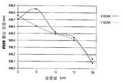
도 8은 본 발명의 하나의 실시예에 따른, 디바이스의 중심으로부터의 오프셋의 함수로서, BERT VCSEL(Vertical Cavity Surface Emitting Lasers)의 파장 의존도의 그래프를 도시한다.
도 9는 본 발명의 하나의 실시예에 따라, 모드의 파장 변동을 고려할 때, 재료 분산 효과, D(λ)가 표준 포물선형 굴절율 프로파일에 대하여 펄스의 성분들이 균일하게 퍼질 것임을 보여주는 그래프를 도시한다. "청색" 모드는 "적색" 모드보다 늦은 시간에 섬유의 출력부에 도달할 것이다.
도 10은 본 발명의 하나의 실시예에 따라, 코어의 바깥쪽 영역에서 표준 포물선형 굴절율보다 더 낮은 굴절율을 가진 섬유(표준 굴절율은 점선으로 표시되어 있음)가 저차 모드("적색")에 영향을 주지 않으면서, 고차 모드("청색")를 가속시시켜, 재료 분산 효과를 상쇄시키는 것을 보여주는 그래프를 도시한다.
도 11은 본 발명의 하나의 실시예에 따라, 코어의 바깥쪽 영역에서 표준 굴절율 보다 큰 굴절율을 가진 섬유가 저차 모드("적색")에 영향을 주지 않으면서, 고차 모드("청색")를 감속시켜, 재료 분산 효과를 악화시키는 것을 보여주는 그래프를 도시한다. Can be better understood with reference to the following drawings and description of the invention. The components of the figures do not scale, but instead there is an emphasis to explain the principles of the present invention.
Figure 1 shows a graph of the refractive index and material dispersion of pure silica as a function of wavelength, according to one embodiment of the present invention.
Figure 2a shows a perspective view of a first section of a graded index MMF with different mode trajectories, in accordance with one embodiment of the present invention.
Figure 2B shows a perspective view of a second section of a graded index MMF with a standard parabolic refractive index profile matching the speeds of the various modes of advancing the fibers, according to one embodiment of the present invention. All modes are assumed to have the same wavelength as the previous model.
3 shows a graph of a DMD waveform for measuring the arrival time difference of all modes in the GI-MMF, according to one embodiment of the present invention. From the arrival time difference normalized by the length of the fibers, the fibers are graded and sorted to conform to OM3 or OM4 type fibers. Different colors were used for illustrative purposes only. All modes have the same wavelength.
Figures 4A and 4B show graphs of the DMD waveform profiles of two fibers with similar DMD and EMB values, according to one embodiment of the present invention. Both fibers are made from the same fiber cable. Both fibers have an EMB of 4540 MHz-km.
Figures 5A and 5B show eye diagrams for blue and brown fibers according to one embodiment of the present invention. The eye diagram for the blue fiber is shown in FIG. 5A and shows a wider eye opening, which represents a larger signal-to-noise ratio and therefore means to transmit information with fewer errors (better BER performance).
Figure 6 shows a graph of BER traces of blue and brown fibers as a function of received power, in accordance with one embodiment of the present invention. Note that for a received optical power of -9.9 dBm (minimum optical power for 1 OGBASE-SR), the difference in BER performance is more than 10 2 .
Figure 7 shows a graph illustrating that minimum mode dispersion requires all modes to reach the output end of the fiber (described for the two low order modes) simultaneously, according to one embodiment of the present invention. In the previous implementation, the modes were assumed to have the same wavelength.
Figure 8 shows a graph of wavelength dependence of BERT VCSEL (Vertical Cavity Surface Emitting Lasers) as a function of offset from the center of the device, according to one embodiment of the present invention.
Figure 9 shows a graph showing that the material dispersion effect, D ([lambda]), will uniformly spread the components of the pulse for a standard parabolic refractive index profile, taking into account the wavelength variation of the mode, according to one embodiment of the present invention . The "blue" mode will reach the output of the fiber at a later time than the "red" mode.
Figure 10 shows that, in accordance with one embodiment of the present invention, fibers having a refractive index lower than the standard parabolic refractive index (the standard refractive index is indicated by the dashed line) in the outer region of the core are affected by the lower order mode ("Blue") is accelerated, without giving a negative value, to compensate for the material dispersion effect.
Figure 11 shows that a fiber having a refractive index greater than the standard refractive index in the outer region of the core does not affect the lower order mode ("red") and the higher order mode And decelerating the material dispersion effect, thereby deteriorating the material dispersion effect.
본 발명은 굴절율 프로파일을 가진 멀티모드 광섬유 케이블이 상이한 방출 패턴으로 상이한 광 파장을 가지는 모드들을 방출하는 광원과 함께 사용될 때, 재료 분산을 물론 모드 분산을 보상하도록 설계될 수 있다는 발견을 이용한다. 제안된 멀티모드 광섬유 케이블은 전체적인 모드 분산을 줄이기 위해 섬유 모드로 연결된 때 레이저 런치 모드의 공간적인 스펙트럼 분포에 대하여 보상한다. 개시된 멀티모드 광섬유 케이블은 모드 분산을 감소시키기 위해 멀티모드 광섬유 케이블의 굴절율 프로파일 및 VCSEL의 파장 의존도를 밸런싱함으로써, 향상된 비트에러율(BER)을 나타낸다. 개시된 멀티모드 광섬유 케이블은 또한 신호가 수용가능한 에러율로 전송될 수 있는 최대 거리를 증가시킨다. 멀티모드 광섬유 케이블의 굴절율 프로파일은 광원 내에서 방출된 광 파장의 공간적 분포를 보상하기 위해 더 큰 방사상 오프셋에서, (DMD의 표준 그래픽 도면에 도시된 바와 같이 ps/m으로) 좌측으로 시프트하는 DMD(Differential Mode Delay) 파형을 나타낸다. The present invention makes use of the discovery that a multimode fiber optic cable with a refractive index profile can be designed to compensate for mode dispersion as well as material dispersion when used with a light source emitting modes with different light wavelengths in different emission patterns. The proposed multimode fiber optic cable compensates for the spatial spectrum distribution of the laser launch mode when connected in fiber mode to reduce overall mode dispersion. The disclosed multimode fiber optic cable exhibits an improved bit error rate (BER) by balancing the refractive index profile of the multimode fiber optic cable and the wavelength dependency of the VCSEL to reduce mode dispersion. The disclosed multimode fiber optic cable also increases the maximum distance a signal can be transmitted at an acceptable error rate. The refractive index profile of the multimode fiber-optic cable is shifted to the left (at ps / m as shown in the standard graphic drawing of the DMD) at a larger radial offset to compensate for the spatial distribution of the light wavelength emitted in the light source Differential Mode Delay) waveform.
본 명세서에서, 우리는 이러한 효과를 글래스 광 섬유에 관련짓는다. 그러나, 본 발명은 플라스틱 광섬유(POF) 및 다른 도파관 구조에도 동등하게 적용가능하다. In this specification, we associate this effect with glass fiber optics. However, the present invention is equally applicable to plastic optical fibers (POF) and other waveguide structures.
재료 분산 및 모드 분산 효과를 모두 보상하는 멀티모드 섬유를 제조하는 방법이 제공된다. 본 방법은 먼저 레이저를 사용하여 멀티모드 섬유로 런칭되는 광 방사선의 펄스로부터 야기되는 기준 멀티모드 섬유 내의 재료 및 모드 분산의 크기를 판정하는 단계를 포함한다. 본 방법은 그 다음 기준 멀티모드 광섬유 케이블 내에 존재하는 재료 분산의 적어도 일부분을 보상하는 향상된 멀티모드 섬유에 대한 향상된 굴절율 프로파일을 설계하는 단계를 포함한다. There is provided a method of manufacturing a multimode fiber that compensates both for material dispersion and mode dispersion effects. The method includes first determining the magnitude of material and mode dispersion in the reference multimode fiber resulting from a pulse of light radiation launched with the laser using the laser. The method then includes designing an enhanced refractive index profile for the enhanced multimode fiber that compensates for at least a portion of the material dispersion present in the reference multimode fiber optic cable.
도 3을 참조하면, 기준 멀티모드 섬유 내의 재료 및 모드 분산의 크기를 판정하는 것은 먼저 수정된 DMD 측정 테스트 방법을 구현할 것을 요구한다. 여기서, 광 방사선 중 시간상으로 짧고 스펙트럼상으로 순수한 광 펄스가 레이저에 의해 발생되고 전송되고, 테스트 중인 기준 MMF의 코어로 런칭된다. 광 방사선의 광 펄스는 먼저 섬유의 중앙축을 따라 런칭되고, 출력 펄스 파형은 포토-디텍터 및 샘플링 오실로스코프로 측정된다. 출력 펄스 파형은 후속한 분석을 위해 저장된다. 런칭된 광 방사선의 광 펄스는 기준 MMF의 중앙 코어로부터 소정의 방사상 거리만큼, 전형적으로 1 또는 2 마이크로미터 옮겨지고, 출력 파형은 다시 측정되고 기록된다. 이러한 과정은 MMF의 코어를 가로질러, 중앙에서 코어-크래이딩 인터페이스에 근접한 중앙으로부터 방사상 거리 X까지 반복된다. 예를 들어, X는 50마이크로미터의 코어 직경에 대하여 대략 23 마이크로미터(±5마이크로미터)이다. 주어진 방사상 런치 오프셋에 대한 모드만 여기됨을 보장하기 위해, 작은 직경의 단일모드 섬유가 MMF의 코어로 광 방사선의 광 펄스를 런칭하기 위해 사용되는 것이 바람직하다.Referring to FIG. 3, determining the size of material and mode dispersion in the reference multimode fiber requires first implementing a modified DMD measurement test method. Here, a short, spectrally pure optical pulse of light in time is generated and transmitted by the laser and launched into the core of the reference MMF under test. The optical pulse of optical radiation is first launched along the center axis of the fiber, and the output pulse waveform is measured with a photo-detector and a sampling oscilloscope. The output pulse waveform is stored for subsequent analysis. The optical pulses of launched optical radiation are shifted by a predetermined radial distance, typically 1 or 2 micrometers, from the central core of the reference MMF, and the output waveform is measured and recorded again. This process is repeated across the core of the MMF, from the center to the radial distance X from the center close to the core-crading interface. For example, X is approximately 23 micrometers (± 5 micrometers) for a core diameter of 50 micrometers. In order to ensure that only the mode for a given radial launch offset is excited, it is desirable that a small diameter monomode fiber is used to launch optical pulses of light radiation into the core of the MMF.
도 4a 및 4b를 참조하면, 2개의 MMF(청색 MMF 및 갈색 MMF)에 대한 결과적인 출력 파형의 예가 도시되어 있다. 각각의 방사상 오프셋에 대한 파형은 수직 축을 따라 도시되어 있고, 각각의 파형의 펄스 지연은 수평축을 따라 도시되어 있다. 이상적으로, 모든 펄스는 표준 포물선형 굴절율 프로파일에 대하여 동시에 섬유의 출력단에 도달해야 한다. 그러나, 굴절율 프로파일의 균일성의 불완벽함은 출력 파형의 시간적인 시프트를 야기한다. MMF의 DMD 또는 모드 분산은 가장 빠른 펄스의 리딩 에지와 가장 느린 펄스의 폴링 에지 간의 도달 시간 차로부터 런치 펄스 시간 폭을 뺌으로써 계산된다.Referring to Figures 4A and 4B, an example of the resulting output waveform for two MMFs (blue MMF and brown MMF) is shown. The waveform for each radial offset is shown along the vertical axis, and the pulse delay of each waveform is shown along the horizontal axis. Ideally, all pulses should reach the output of the fiber simultaneously for a standard parabolic refractive index profile. However, the imperfectness of the uniformity of the refractive index profile causes a time shift of the output waveform. The DMD or mode dispersion of the MMF is calculated by subtracting the launch pulse duration from the arrival time difference between the leading edge of the fastest pulse and the falling edge of the slowest pulse.
TIA-455-220-A에 명시된 표준 DMD 테스트 방법을 사용하여, MMF 섬유는 레이저 최적화된 것으로 분류될 수 있고(즉, OM3), (이론상) 300m까지의 10Gb/s 이더넷 통신을 지원할 수 있다. 섬유는 코어의 방사상 영역 내의 최대 모드 분산(즉, DMD)를 특정하는 6개의 마스크 탬플릿 중 하나를 충족해야 한다. 섬유가 (TIA에 의해 특정될) 더 엄격한 DMD 요구사항을 충족한다면, 그 섬유는 더 먼 거리를 지원할 수 있는 OM4로 분류된다. DMD에 의해 측정된 낮은 모드 분산은 더 높은 MMF 성능으로 해석될 것으로 생각된다.Using the standard DMD test method specified in TIA-455-220-A, MMF fibers can be classified as laser optimized (ie, OM3) and can (in theory) support 10 Gb / s Ethernet communications up to 300 meters. The fiber must meet one of the six mask templates specifying the maximum mode dispersion (i.e., DMD) within the radial region of the core. If the fibers meet the more stringent DMD requirements (as specified by the TIA), the fibers are classified as OM4, which can support longer distances. The low mode dispersion measured by the DMD is believed to be interpreted as higher MMF performance.
MMF의 대역폭 성능을 특징짓는 다른 유용한 미터법은 메가헤르츠키로미터(MHzkm)단위로 표현되는 유효 모드 대역폭(EMF: Effective Modal bandwidth)이다. EMB는 DMD 측정에서 획득된 펄스 파형으로부터 유도된 계산된 미터법이다. 측정된 출력 파형의 세트는 결과적인 출력 신호 파형을 모델링하기 위해 합해진다. 주파수 도메인으로의 수학적 변환을 사용하여, 출력 및 입력 파형은 섬유의 대역폭을 계산하기 위해 수치적으로 분할된다. 10개의 대표적인 VCSEL의 방사상 광 파워 분포를 시뮬레이팅하기 위한 가중치 함수를 적용하여, 최소 계산된 EMB가 판정된다(min EMBc). min EMBc 미터법을 사용하여, 섬유의 EMB는 1.13의 증배율에 의해 계산된다(즉, EMB = 1.13 x min EMBc). 고속 이더넷 표준에 명시된 OM3 및 OM4로서 특징지어지기 위해, 이러한 섬유에 대한 EMB 값은 각각 적어도 2000MHz-km and 4700MHz-km이여야 한다. Another useful metric that characterizes the bandwidth performance of an MMF is the effective modal bandwidth (EMF) expressed in megahertz kilometer (MHz km). The EMB is a computed metric derived from the pulse waveform obtained from the DMD measurement. The set of measured output waveforms are summed to model the resulting output signal waveform. Using mathematical transforms into the frequency domain, the output and input waveforms are numerically divided to compute the bandwidth of the fiber. The minimum calculated EMB is determined by applying a weight function to simulate the radial optical power distribution of 10 representative VCSELs (min EMBc). min Using the EMBc metric, the EMB of the fiber is calculated by the multiplication factor of 1.13 (i.e., EMB = 1.13 x min EMBc). To be characterized as OM3 and OM4 as specified in the Fast Ethernet standard, the EMB values for these fibers shall be at least 2000 MHz-km and 4700 MHz-km, respectively.
표준 DMD 및 EMB가 (TIA-455-220-A에 명시된) 단색성 소스를 사용하여 온타임 지연 측정을 기초로 하는 기술을 사용하기 때문에, 그들은 도 4a 및 4b에 도시된 두 섬유를 구별할 수 없다. 동일한 광 케이블 내에 포함된 청색 및 갈색 섬유는 DMD 및 EMB의 미터법에 의해 사실상 동일하다(표 1 참조). 그럼에도 불구하고, 그들은 도 5a 및 5b에 도시된 아이 다이어그램을 분석함으로써 벤치마킹되는 측정된 채널 성능 및 및 도 6에 도시된 비트 에러율 테스트(BERT) 성능에서 큰 차이를 나타낸다. Because standard DMDs and EMBs use techniques based on on-time delay measurements using monochromatic sources (specified in TIA-455-220-A), they can distinguish between the two fibers shown in Figures 4A and 4B none. The blue and brown fibers contained in the same optical cable are virtually identical by the metric method of DMD and EMB (see Table 1). Nonetheless, they exhibit large differences in the measured channel performance benchmarked by analyzing the eye diagram shown in FIGS. 5A and 5B and the bit error rate test (BERT) performance shown in FIG.
(5 내지 18 마이크로미터)Internal mask DMD
(5 to 18 micrometers)
(0 내지 23 마이크로미터)External mask DMD
(0 to 23 micrometers)
(EMB=1.13×EMBc)EMB
(EMB = 1.13 x EMBc)
BER 시스템 성능과 DMD 파형 시프트 사이의 관계가 발견되었다. 근본 원인은 큰 방사상 오프셋에서 좌측 및 우측 DMD 시간 파형 시프트 및 VCSEL의 파장 방출 패턴과 관련된다. 이러한 차이는 도 4a 및 4b에서 관찰될 수 있다. VCSEL은 방출 영역 위로 약간씩 상이한 파장을 가진 광의 분포를 야기하는 복수의 가로방향 모드와 연결된 하나의 세로방향 모드를 방출한다. 각각의 VCSEL 모드는 정의된 극성 방출 패턴을 가진다. 이러한 물리적 효과는 본 명세서에서 반경 의존 파장을 가진 극성 패턴이라 한다. 각각의 DMD 파형 프로파일에 대한 펄스 지연 또는 또는 반경 의존 파장을 가진 극성 패턴 내에 차이가 존재한다면, 재료 분산 및 모드 분산 효과는 모두 보상될 수 있고, 이전 방법보다 모드 분산을 더 감소시킬 수 있다. A relationship between BER system performance and DMD waveform shift was found. The root cause is related to the left and right DMD time waveform shifts and the wavelength emission pattern of the VCSEL at large radial offsets. This difference can be observed in Figures 4A and 4B. The VCSEL emits one longitudinal mode coupled with a plurality of transverse modes that cause a distribution of light with slightly different wavelengths over the emission region. Each VCSEL mode has a defined polarity emission pattern. This physical effect is referred to herein as a polar pattern having a radial dependent wavelength. If there is a difference in the polarity pattern with pulse delay or radial dependent wavelengths for each DMD waveform profile, both material dispersion and mode dispersion effects can be compensated and further reduce the mode dispersion than previous methods.
섬유 모드의 전파시 이러한 방출 패턴의 영향은 아래에 설명된다. (식 2에 서술된 α값을 기초로 하는) 표준 포물선 굴절율 프로파일은 모든 모드가 실질적으로 동일한 파장(색상)을 가진다고 가정하면, 현재 그 섬유를 통해 진행하는 모든 모드의 퍼짐을 최소화하도록 설계되어 있다. 도 7을 참조하면, 레이저 소스 방출 패턴 및 파장 분포 효과는 완전히 무시되었다. The effect of this emission pattern upon propagation of the fiber mode is described below. The standard parabolic refractive index profile (based on the alpha value described in Equation 2) is designed to minimize the spread of all modes that are currently traveling through the fiber, assuming that all modes have substantially the same wavelength (color) . Referring to FIG. 7, the laser source emission pattern and the wavelength distribution effect are completely ignored.
그러나, 고속 광 송수신기에서 사용된 VCSEL은 디바이스의 애퍼어처를 가로질러 상이한 파장을 가진 광(모드)을 방출한다. 더 긴 파장은 면에 수직으로 더 작은 각도로 방출되고, 짧은 파장은 더 큰 각도로 방출된다(극성 방출 패턴). 도 8을 참조하면, 이러한 VCSEL 공간적 스펙트럼 분포는 섬유 모드로 연결될 때 보존된다. 오늘날 사용되는 표준 포물선형 DMD 파형 프로파일은 VCSEL의 애퍼어처를 가로질러 동일한 파장의 광에 대하여만 유효하며, 여기서 모든 연결된 섬유 모드는 동일한 중심 파장을 가질 것으로 생각된다. MMF로 런칭되는 광 파장의 공간적 분포는 모드들이 그들의 반경 의존 파장과 함께 재료 분산 효과에 의해 영향을 받기 때문에 새로운 바람직한 DMD 파형 프로파일을 요구한다. 모드 분산과 연관된 반경 의존 방출 패턴의 효과는 도 9에 도시되어 있다. 저차 모드는 더 긴 파장("적색")을 가지고, 그러므로 더 짧은 파장("청색")을 가진 고차 모드 보다 더 빠르게 진행한다. However, VCSELs used in high speed optical transceivers emit light (modes) having different wavelengths across the aperture of the device. The longer wavelength is emitted at a smaller angle perpendicular to the plane, and the shorter wavelength is emitted at a larger angle (polarity emission pattern). Referring to FIG. 8, this VCSEL spatial spectrum distribution is preserved when connected in fiber mode. The standard parabolic DMD waveform profile used today is only valid for light of the same wavelength across the aperture of the VCSEL, where all connected fiber modes are assumed to have the same central wavelength. The spatial distribution of optical wavelengths launched into the MMF requires a new desirable DMD waveform profile because the modes are affected by the material dispersion effect with their radial dependent wavelengths. The effect of the radially-dependent emission pattern associated with mode dispersion is shown in Fig. The lower order mode has a longer wavelength ("red") and therefore proceeds faster than the higher order mode with shorter wavelength ("blue").
우리의 실험 데이터를 기초로, DMD 프로파일 내의 방사상 펄스 파형의 "좌측" 시프트(더 작은 값의 ps/m)를 나타내는 섬유는 MMF 코어의 바깥 영역에 더 낮은 표준 포물선형 굴절율에 대응한다. 이는 도 4a에서 청색 섬유에 대한 DMD 파형 프로파일에서 큰 방사상 오프셋에서 관찰된다. 더 낮은 차수의 모드는 굴절율의 바깥 영역을 통해 진행하지 않으므로, 이러한 시프트에 의해 영향을 받지 않는다. 더 높은 차수의 모드는 그들이 소위 표준 포물선형 굴절율 프로파일 보다 낮은 영역으로 진행하고, 그들이 사실상 "적색" 광을 따라잡기 때문에, 도 9에 도시된 바와 같이, 파장 의존 굴절율의 결과로서 감속된다(도 10 참조)Based on our experimental data, fibers representing the "left" shift (smaller value of ps / m) of the radial pulse waveform in the DMD profile correspond to a lower standard parabolic refractive index in the outer region of the MMF core. This is observed in Figure 4A at a large radial offset in the DMD waveform profile for blue fibers. A lower order mode is not affected by this shift since it does not proceed through the outer region of the refractive index. The higher order modes are decelerated as a result of the wavelength dependent refractive index, as shown in FIG. 9, as they proceed to a region lower than the so-called standard parabolic refractive index profile and because they catch up with the "red & Reference)
큰 방사상 오프셋 파형에서 "우측" 시프트를 가진 섬유에 대하여, 굴절율은 코어의 바깥쪽 영역에서 표준 포물선형 굴절율 보다 더 높다. 이는 도 4b에 도시된 바와 같이 높은 방사상 오프셋에서 갈색 섬유의 DMD 파형에서 볼 수 있다. 더 낮은 차수의 모드는 그들이 그 영역을 통해 진행하지 않으므로 굴절율의 이러한 시프트에 의해 영향을 받지 않을 것이다. 도 9에 도시된 바와 같이, 파장 의존 굴절율에 의해 감속되는 더 높은 차수의 모드는 표준 포물선형 굴절율 프로파일보다 더 높은 영역을 통해 진행할 것이므로 "청색" 광을 훨씬 더 감속시킬 것이다(도 11 참조). For fibers with a "right" shift in a large radially offset waveform, the refractive index is higher than the standard parabolic refractive index in the outer region of the core. This can be seen in the DMD waveform of the brown fibers at high radial offsets as shown in Fig. 4b. Lower order modes will not be affected by this shift in refractive index as they do not go through the area. As shown in FIG. 9, the higher order mode decelerated by the wavelength dependent refractive index will progress through the higher region than the standard parabolic refractive index profile, thus further slowing the "blue" light (see FIG. 11).
본 출원인은 VCSEL의 스펙트럼 분포 및 극성 방출 패턴이 무시될 수 없으므로, 현재 이상적인 DMD 파형 프로파일이 최소 모드 분산을 위해 최적이 아닌 것으로 판단하였다. 이러한 발견을 기초로, VCSEL 모드의 상이한 파장을 고려함으로써, 모드 분산은 감소될 수 있고 모드 파장이 보상된 멀티모드 광섬유 케이블을 야기한다. Applicants have determined that the present ideal DMD waveform profile is not optimal for minimum mode dispersion since the spectral distribution and polarity emission pattern of the VCSEL can not be ignored. Based on this finding, by considering the different wavelengths of the VCSEL mode, the mode dispersion can be reduced and the mode wavelength causes a compensated multimode fiber optic cable.
모드 분산을 최소화하는 것은 주로 모드 파티션 잡음, 모드 잡음 등과 같은 VCSEL과 관련될 다른 패널티를 포함한) 감쇄에 의해 제한되는 섬유로 모드 파장이 보상된 MMF을 변환할 수 있다. IEEE 1OGBASE-SR 링크 모델을 사용할 때, 이러한 향상은 잠재적으로 최대 채널 링크 거리를 125m에서 잠재적으로 200m 이상까지 증가시킬 수 있을 것으로 예상된다. VCSEL로부터 런칭된 광의 공간적 및 스펙트럼 분포를 고려함으로써, 향상된 굴절율 프로파일은 모드의 파장 의존도의 적어도 일부분을 보상하는 향상된 MMF에 대하여 설계될 수 있고, 이는 모드 분산이 종래의 보상 방법보다 더 감소될 수 있게 한다.Minimizing the mode dispersion can convert the mode-compensated MMF to fibers limited by attenuation, mainly including other penalties associated with VCSELs such as mode partition noise, mode noise, and the like. When using the IEEE 1OGBASE-SR link model, this improvement is expected to potentially increase the maximum channel link distance from 125m to potentially over 200m. By considering the spatial and spectral distribution of the light launched from the VCSEL, the improved refractive index profile can be designed for an enhanced MMF that compensates for at least a portion of the wavelength dependence of the mode, which allows the mode dispersion to be reduced further than conventional compensation methods do.
본 발명의 특정한 형태가 본 명세서에 서술되고 도시되어 있으나, 본 명세서의 교시를 기초로, 본 명세서에서 서술된 내용 및 그것의 더 넓은 형태를 벗어나지 않고 수정 및 변형이 이루어질 수 있음은 당업자들에게 명백할 것이다. 그러므로, 첨부된 청구항은 본 명세서에 서술된 본 발명의 정신 및 범위 내에 있는 이러한 수정 및 변형을 모두 포함한다. 또한, 본 발명은 첨부된 청구항에 의해 정의됨이 이해될 것이다. 따라서, 본 발명은 첨부된 청구항 및 그 동등물을 외에 한정되지 않아야 한다.Although specific forms of the invention are described and illustrated herein, it will be apparent to those skilled in the art, on the basis of the teachings herein, that modifications and variations can be made without departing from the teachings herein and the broader aspects thereof something to do. It is therefore intended that the appended claims be construed to include all such modifications and changes as fall within the spirit and scope of the invention as described herein. It is also to be understood that the invention is defined by the appended claims. Accordingly, the invention should not be limited except as by the appended claims and their equivalents.
Claims (20)
기준 멀티모드 광섬유 케이블에 레이저를 연결하는 단계;
각각의 광 방사선 펄스가 상이한 방사사 오프셋으로 런칭되도록, 상기 기준 멀티모드 광섬유 케이블로 상기 레이저에 의한 복수의 광 방사선 펄스를 발생시키고 런칭시키는 단계;
각각의 방사상 오프셋에서 각각의 광 펄스에 대한 펄스 지연과 함께 DMD 파형 프로파일을 판정하는 단계;
상기 방사상 오프셋이 증가됨에 따라, 펄스 지연 차가 좌측 또는 우측 DMD 시간 파형 시프트를 형성하는지 판정하는 단계;
각각의 DMD 파형 프로파일에 존재하는 임의의 펄스 지연 차를 보상하고, 상기 기준 멀티모드 광섬유 케이블에 존재하는 재료 분산의 적어도 일부를 보상하는 굴절율 프로파일을 가진 상기 자가 보상형 멀티모드 광섬유를 설계하는 단계; 및
상기 자가 보상형 멀티모드 광섬유를 상기 설계에 따라 제조하는 단계를 포함하고,
상기 굴절율 프로파일은 상기 기준 멀티모드 광섬유 케이블이 상기 방사상 오프셋이 증가됨에 따라 좌측 DMD 시간 파형 시프트를 나타낸다면, 상기 기준 멀티모드 광섬유 케이블의 코어의 바깥 영역에서 표준 포물선형 굴절율보다 낮은 굴절율을 포함하고; 또는
상기 굴절율 프로파일은 상기 기준 멀티모드 광섬유 케이블이 상기 방사상 오프셋이 증가됨에 따라 우측 DMD 시간 파형 시프트를 나타낸다면, 상기 기준 멀티모드 광섬유 케이블의 코어의 바깥 영역에서 표준 포물선형 굴절율보다 높은 굴절율을 포함하는 것을 특징으로 하는 재료 분산 및 모드 분산 효과를 모두 보상하는 자가 보상형 멀티모드 광섬유 케이블을 제조하는 방법.A method of manufacturing a self-compensating multimode optical fiber cable that compensates both material dispersion and mode dispersion effects,
Connecting a laser to a reference multimode fiber optic cable;
Generating and launching a plurality of optical radiation pulses by the laser with the reference multimode fiber optic cable such that each optical radiation pulse is launched with a different radial offset;
Determining a DMD waveform profile with a pulse delay for each light pulse at each radial offset;
Determining if the pulse delay difference forms a left or right DMD time waveform shift as the radial offset is increased;
Compensating for any pulse delay differences present in each DMD waveform profile and designing the self-compensating multimode optical fiber with a refractive index profile that compensates for at least some of the material dispersion present in the reference multimode fiber optic cable; And
Compensating multi-mode optical fiber according to the design,
Wherein the refractive index profile comprises a refractive index lower than a standard parabolic refractive index in an outer region of the core of the reference multimode fiber optic cable if the reference multimode fiber optic cable exhibits a left DMD time waveform shift as the radial offset is increased; or
Wherein the refractive index profile includes a refractive index greater than a standard parabolic refractive index in an outer region of the core of the reference multimode fiber optic cable if the reference multimode fiber optic cable exhibits a right DMD time waveform shift as the radial offset is increased A method for fabricating a self-compensating multimode fiber optic cable that compensates both material dispersion and mode dispersion effects.
각각의 광 방사선 펄스가 상이한 방사상 오프셋으로 런칭되도록, 기준 멀티모드 광섬유 케이블로 복수의 광 방사선 펄스를 발생시키고 런칭하는 단계;
각각의 방사상 오프셋에서 각각의 광 펄스에 대한 펄스 지연과 함께 DMD 파형 프로파일을 판정하는 단계;
상기 방사상 오프셋이 증가됨에 따라, 펄스 지연 차가 좌측 또는 우측 DMD 시간 파형 시프트를 형성하는지 판정하는 단계;
각각의 DMD 파형 프로파일 내에 존재하는 임의의 펄스 지연 차를 보정함으로써 상기 기준 멀티모드 광섬유 케이블 내에 존재하는 재료 분산의 적어도 일부를 보상하는 상기 자가 보상형 멀티모드 광섬유 케이블에 대한 굴절율 프로파일을 설계하는 단계; 및
상기 자가 보상형 멀티모드 광섬유 케이블을 상기 설계에 따라 제조하는 단계를 포함하고,
상기 굴절율 프로파일은 상기 기준 멀티모드 광섬유 케이블이 상기 방사상 오프셋이 증가됨에 따라 좌측 DMD 시간 파형 시프트를 나타낸다면, 상기 기준 멀티모드 광섬유 케이블의 코어의 바깥 영역에서 표준 포물선형 굴절율보다 낮은 굴절율을 포함하고; 또는
상기 굴절율 프로파일은 상기 기준 멀티모드 광섬유 케이블이 상기 방사상 오프셋이 증가됨에 따라 우측 DMD 시간 파형 시프트를 나타낸다면, 상기 기준 멀티모드 광섬유 케이블의 코어의 바깥 영역에서 표준 포물선형 굴절율보다 높은 굴절율을 포함하는 재료 분산 및 모드 분산 효과를 모두 보상하는 자가 보상형 멀티모드 광섬유 케이블을 설계하는 방법.A method of designing a self-compensating multimode fiber optic cable that compensates both material dispersion and mode dispersion effects,
Generating and launching a plurality of optical radiation pulses with a reference multimode fiber optic cable such that each optical radiation pulse is launched at a different radial offset;
Determining a DMD waveform profile with a pulse delay for each light pulse at each radial offset;
Determining if the pulse delay difference forms a left or right DMD time waveform shift as the radial offset is increased;
Designing a refractive index profile for the self-compensating multimode fiber optic cable that compensates for at least some of the material dispersion present in the reference multimode fiber optic cable by correcting any pulse delay differences present in each DMD waveform profile; And
And fabricating the self-compensating multi-mode optical fiber cable according to the design,
Wherein the refractive index profile comprises a refractive index lower than a standard parabolic refractive index in an outer region of the core of the reference multimode fiber optic cable if the reference multimode fiber optic cable exhibits a left DMD time waveform shift as the radial offset is increased; or
Wherein the refractive index profile is selected such that the reference multimode fiber optic cable exhibits a right DMD time waveform shift as the radial offset is increased and the refractive index profile of the reference multimode fiber optic cable comprises a material having a refractive index higher than a standard parabolic refractive index, A method of designing a self - compensating multimode fiber optic cable that compensates both dispersion and mode dispersion effects.
Applications Claiming Priority (5)
| Application Number | Priority Date | Filing Date | Title |
|---|---|---|---|
| US23453009P | 2009-08-17 | 2009-08-17 | |
| US61/234,530 | 2009-08-17 | ||
| US23550609P | 2009-08-20 | 2009-08-20 | |
| US61/235,506 | 2009-08-20 | ||
| PCT/US2010/045790 WO2011022422A1 (en) | 2009-08-17 | 2010-08-17 | Self-compensating multi-mode fiber |
Publications (2)
| Publication Number | Publication Date |
|---|---|
| KR20120061891A KR20120061891A (en) | 2012-06-13 |
| KR101597613B1 true KR101597613B1 (en) | 2016-02-25 |
Family
ID=43063821
Family Applications (1)
| Application Number | Title | Priority Date | Filing Date |
|---|---|---|---|
| KR1020127006874A KR101597613B1 (en) | 2009-08-17 | 2010-08-17 | Self-compensating multi-mode fiber |
Country Status (6)
| Country | Link |
|---|---|
| US (1) | US8398900B2 (en) |
| EP (1) | EP2467744B1 (en) |
| JP (1) | JP5551249B2 (en) |
| KR (1) | KR101597613B1 (en) |
| CN (1) | CN102483486B (en) |
| WO (1) | WO2011022422A1 (en) |
Families Citing this family (28)
| Publication number | Priority date | Publication date | Assignee | Title |
|---|---|---|---|---|
| NL1024015C2 (en) | 2003-07-28 | 2005-02-01 | Draka Fibre Technology Bv | Multimode optical fiber provided with a refractive index profile, optical communication system using this and method for manufacturing such a fiber. |
| FR2932932B1 (en) | 2008-06-23 | 2010-08-13 | Draka Comteq France Sa | MULTIPLEX WAVE LENGTH OPTIC SYSTEM WITH MULTIMODE OPTIC FIBERS |
| FR2933779B1 (en) | 2008-07-08 | 2010-08-27 | Draka Comteq France | MULTIMODE OPTIC FIBERS |
| FR2940839B1 (en) | 2009-01-08 | 2012-09-14 | Draka Comteq France | INDEX GRADIENT MULTIMODAL OPTICAL FIBER, METHODS FOR CHARACTERIZATION AND MANUFACTURE OF SUCH A FIBER |
| FR2946436B1 (en) | 2009-06-05 | 2011-12-09 | Draka Comteq France | MULTIMODE OPTICAL FIBER WITH LARGE BANDWIDTH WITH AN OPTIMIZED HEAT-SLEEVE INTERFACE |
| FR2953605B1 (en) | 2009-12-03 | 2011-12-16 | Draka Comteq France | MULTIMODE OPTICAL FIBER WITH BROAD BANDWIDTH AND LOW BENDBACK LOSSES |
| US9014525B2 (en) | 2009-09-09 | 2015-04-21 | Draka Comteq, B.V. | Trench-assisted multimode optical fiber |
| FR2953029B1 (en) | 2009-11-25 | 2011-11-18 | Draka Comteq France | MULTIMODE OPTICAL FIBER WITH LARGE BANDWIDTH WITH AN OPTIMIZED HEAT-SLEEVE INTERFACE |
| FR2957153B1 (en) | 2010-03-02 | 2012-08-10 | Draka Comteq France | MULTIMODE OPTICAL FIBER WITH BROAD BANDWIDTH AND LOW BENDBACK LOSSES |
| FR2953030B1 (en) | 2009-11-25 | 2011-11-18 | Draka Comteq France | MULTIMODE OPTICAL FIBER WITH LARGE BANDWIDTH WITH AN OPTIMIZED HEAT-SLEEVE INTERFACE |
| FR2949870B1 (en) | 2009-09-09 | 2011-12-16 | Draka Compteq France | MULTIMODE OPTICAL FIBER HAVING IMPROVED BENDING LOSSES |
| FR2953606B1 (en) | 2009-12-03 | 2012-04-27 | Draka Comteq France | MULTIMODE OPTICAL FIBER WITH BROAD BANDWIDTH AND LOW BENDBACK LOSSES |
| FR2950156B1 (en) | 2009-09-17 | 2011-11-18 | Draka Comteq France | MULTIMODE OPTIC FIBER |
| FR2966256B1 (en) | 2010-10-18 | 2012-11-16 | Draka Comteq France | MULTIMODE OPTICAL FIBER INSENSITIVE TO LOSSES BY |
| FR2971061B1 (en) | 2011-01-31 | 2013-02-08 | Draka Comteq France | BROAD BANDWIDTH OPTICAL FIBER WITH LOW CURB LOSSES |
| DK2482106T5 (en) | 2011-01-31 | 2014-09-22 | Draka Comteq Bv | Multi-mode fiber |
| EP2503368A1 (en) | 2011-03-24 | 2012-09-26 | Draka Comteq B.V. | Multimode optical fiber with improved bend resistance |
| EP2506044A1 (en) | 2011-03-29 | 2012-10-03 | Draka Comteq B.V. | Multimode optical fiber |
| EP2518546B1 (en) | 2011-04-27 | 2018-06-20 | Draka Comteq B.V. | High-bandwidth, radiation-resistant multimode optical fiber |
| DK2541292T3 (en) | 2011-07-01 | 2014-12-01 | Draka Comteq Bv | A multimode optical fiber |
| US9417382B2 (en) | 2013-02-26 | 2016-08-16 | Panduit Corp. | Multimode optical fibers and methods of manufacture thereof |
| PL3058329T3 (en) | 2013-10-15 | 2021-02-08 | Draka Comteq Bv | A method of characterizing a multimode optical fiber link and corresponding methods of fabricating multimode optical fiber links and of selecting multimode optical fibers from a batch of multimode optical fibers |
| US9632244B2 (en) * | 2014-07-28 | 2017-04-25 | Panduit Corp. | Multimode optical fiber and methods of manufacturing thereof |
| US9753216B2 (en) * | 2015-08-27 | 2017-09-05 | Sumitomo Electric Industries, Ltd. | Multimode optical fiber and optical cable including the same |
| US9909952B2 (en) * | 2016-04-29 | 2018-03-06 | Panduit Corp. | Optical fibers and methods associated therewith |
| US20180259370A1 (en) * | 2017-03-08 | 2018-09-13 | Nicolas K. Fontaine | Multimode Fiber Sensor and Sensing Using Forward and Backward Scattering |
| US10502908B2 (en) * | 2017-03-13 | 2019-12-10 | Mellanox Technologies, Ltd. | Long-reach active optical cable |
| CN117639918A (en) * | 2022-08-12 | 2024-03-01 | 武汉光迅科技股份有限公司 | Wave compensation method, device, equipment and readable storage medium |
Citations (3)
| Publication number | Priority date | Publication date | Assignee | Title |
|---|---|---|---|---|
| WO1997033390A1 (en) | 1996-03-08 | 1997-09-12 | Hewlett-Packard Company | Multimode communications systems |
| US6790529B2 (en) | 2001-09-20 | 2004-09-14 | Draka Fibre Technology B.V. | Multimode fiber having a refractive index profile |
| US20050008312A1 (en) | 2003-07-11 | 2005-01-13 | Yun-Geun Jang | Graded-index optical fiber |
Family Cites Families (1)
| Publication number | Priority date | Publication date | Assignee | Title |
|---|---|---|---|---|
| US7646955B2 (en) * | 2004-07-26 | 2010-01-12 | Corning Incorporated | Multimode optical fiber with low differential mode delay |
-
2010
- 2010-08-17 KR KR1020127006874A patent/KR101597613B1/en active IP Right Grant
- 2010-08-17 WO PCT/US2010/045790 patent/WO2011022422A1/en active Application Filing
- 2010-08-17 CN CN201080037032.9A patent/CN102483486B/en active Active
- 2010-08-17 EP EP10748005.5A patent/EP2467744B1/en active Active
- 2010-08-17 JP JP2012525648A patent/JP5551249B2/en active Active
- 2010-08-17 US US12/858,210 patent/US8398900B2/en active Active
Patent Citations (3)
| Publication number | Priority date | Publication date | Assignee | Title |
|---|---|---|---|---|
| WO1997033390A1 (en) | 1996-03-08 | 1997-09-12 | Hewlett-Packard Company | Multimode communications systems |
| US6790529B2 (en) | 2001-09-20 | 2004-09-14 | Draka Fibre Technology B.V. | Multimode fiber having a refractive index profile |
| US20050008312A1 (en) | 2003-07-11 | 2005-01-13 | Yun-Geun Jang | Graded-index optical fiber |
Also Published As
| Publication number | Publication date |
|---|---|
| US20110037183A1 (en) | 2011-02-17 |
| JP2013502614A (en) | 2013-01-24 |
| WO2011022422A1 (en) | 2011-02-24 |
| US8398900B2 (en) | 2013-03-19 |
| EP2467744B1 (en) | 2023-05-10 |
| JP5551249B2 (en) | 2014-07-16 |
| EP2467744A1 (en) | 2012-06-27 |
| CN102483486A (en) | 2012-05-30 |
| KR20120061891A (en) | 2012-06-13 |
| CN102483486B (en) | 2015-05-27 |
Similar Documents
| Publication | Publication Date | Title |
|---|---|---|
| KR101597613B1 (en) | Self-compensating multi-mode fiber | |
| US8260103B2 (en) | Multimode optical fibers | |
| CN101738688B (en) | Multimode optical system | |
| KR100526516B1 (en) | Graded-index optical fiber for high bit-rate and local area network | |
| EP3177948B1 (en) | Method of design and manufacture of a multimode optical fiber | |
| EP3058329B1 (en) | A method of characterizing a multimode optical fiber link and corresponding methods of fabricating multimode optical fiber links and of selecting multimode optical fibers from a batch of multimode optical fibers | |
| KR20120061882A (en) | Multimode fiber having improved reach | |
| RU2611203C2 (en) | Broadband multimode optic fibre optimized for multimode and single-mode transmissions | |
| US10114171B2 (en) | Multimode optical fiber and methods of manufacturing thereof | |
| Yabre | Theoretical investigation on the dispersion of graded-index polymer optical fibers | |
| JP2014500975A (en) | Method for designing and selecting an optical fiber for use with a transmitter optical subassembly | |
| US10180375B2 (en) | Optical fibers and methods associated therewith | |
| CN212343772U (en) | Optical channel bandwidth analyzer | |
| Pepeljugoski | Next generation high-speed multimode fiber links and their specifications |
Legal Events
| Date | Code | Title | Description |
|---|---|---|---|
| A201 | Request for examination | ||
| A302 | Request for accelerated examination | ||
| E701 | Decision to grant or registration of patent right | ||
| GRNT | Written decision to grant | ||
| FPAY | Annual fee payment |
Payment date: 20190220 Year of fee payment: 4 |
|
| FPAY | Annual fee payment |
Payment date: 20200213 Year of fee payment: 5 |