KR101544291B1 - Method of, and apparatus for, measuring the true contents of a cylinder of gas under pressure - Google Patents
Method of, and apparatus for, measuring the true contents of a cylinder of gas under pressure Download PDFInfo
- Publication number
- KR101544291B1 KR101544291B1 KR1020137017159A KR20137017159A KR101544291B1 KR 101544291 B1 KR101544291 B1 KR 101544291B1 KR 1020137017159 A KR1020137017159 A KR 1020137017159A KR 20137017159 A KR20137017159 A KR 20137017159A KR 101544291 B1 KR101544291 B1 KR 101544291B1
- Authority
- KR
- South Korea
- Prior art keywords
- gas
- gas cylinder
- cylinder
- mass
- sensor assembly
- Prior art date
Links
Images


Classifications
-
- G—PHYSICS
- G01—MEASURING; TESTING
- G01N—INVESTIGATING OR ANALYSING MATERIALS BY DETERMINING THEIR CHEMICAL OR PHYSICAL PROPERTIES
- G01N9/00—Investigating density or specific gravity of materials; Analysing materials by determining density or specific gravity
- G01N9/36—Analysing materials by measuring the density or specific gravity, e.g. determining quantity of moisture
-
- G—PHYSICS
- G01—MEASURING; TESTING
- G01F—MEASURING VOLUME, VOLUME FLOW, MASS FLOW OR LIQUID LEVEL; METERING BY VOLUME
- G01F1/00—Measuring the volume flow or mass flow of fluid or fluent solid material wherein the fluid passes through a meter in a continuous flow
- G01F1/76—Devices for measuring mass flow of a fluid or a fluent solid material
- G01F1/86—Indirect mass flowmeters, e.g. measuring volume flow and density, temperature or pressure
-
- F—MECHANICAL ENGINEERING; LIGHTING; HEATING; WEAPONS; BLASTING
- F17—STORING OR DISTRIBUTING GASES OR LIQUIDS
- F17C—VESSELS FOR CONTAINING OR STORING COMPRESSED, LIQUEFIED OR SOLIDIFIED GASES; FIXED-CAPACITY GAS-HOLDERS; FILLING VESSELS WITH, OR DISCHARGING FROM VESSELS, COMPRESSED, LIQUEFIED, OR SOLIDIFIED GASES
- F17C13/00—Details of vessels or of the filling or discharging of vessels
- F17C13/02—Special adaptations of indicating, measuring, or monitoring equipment
- F17C13/023—Special adaptations of indicating, measuring, or monitoring equipment having the mass as the parameter
-
- G—PHYSICS
- G01—MEASURING; TESTING
- G01F—MEASURING VOLUME, VOLUME FLOW, MASS FLOW OR LIQUID LEVEL; METERING BY VOLUME
- G01F15/00—Details of, or accessories for, apparatus of groups G01F1/00 - G01F13/00 insofar as such details or appliances are not adapted to particular types of such apparatus
- G01F15/06—Indicating or recording devices
- G01F15/061—Indicating or recording devices for remote indication
- G01F15/063—Indicating or recording devices for remote indication using electrical means
-
- G—PHYSICS
- G01—MEASURING; TESTING
- G01G—WEIGHING
- G01G17/00—Apparatus for or methods of weighing material of special form or property
- G01G17/04—Apparatus for or methods of weighing material of special form or property for weighing fluids, e.g. gases, pastes
-
- G—PHYSICS
- G01—MEASURING; TESTING
- G01G—WEIGHING
- G01G17/00—Apparatus for or methods of weighing material of special form or property
- G01G17/04—Apparatus for or methods of weighing material of special form or property for weighing fluids, e.g. gases, pastes
- G01G17/06—Apparatus for or methods of weighing material of special form or property for weighing fluids, e.g. gases, pastes having means for controlling the supply or discharge
-
- G—PHYSICS
- G01—MEASURING; TESTING
- G01G—WEIGHING
- G01G3/00—Weighing apparatus characterised by the use of elastically-deformable members, e.g. spring balances
- G01G3/12—Weighing apparatus characterised by the use of elastically-deformable members, e.g. spring balances wherein the weighing element is in the form of a solid body stressed by pressure or tension during weighing
- G01G3/16—Weighing apparatus characterised by the use of elastically-deformable members, e.g. spring balances wherein the weighing element is in the form of a solid body stressed by pressure or tension during weighing measuring variations of frequency of oscillations of the body
-
- G—PHYSICS
- G01—MEASURING; TESTING
- G01N—INVESTIGATING OR ANALYSING MATERIALS BY DETERMINING THEIR CHEMICAL OR PHYSICAL PROPERTIES
- G01N9/00—Investigating density or specific gravity of materials; Analysing materials by determining density or specific gravity
-
- G—PHYSICS
- G01—MEASURING; TESTING
- G01N—INVESTIGATING OR ANALYSING MATERIALS BY DETERMINING THEIR CHEMICAL OR PHYSICAL PROPERTIES
- G01N9/00—Investigating density or specific gravity of materials; Analysing materials by determining density or specific gravity
- G01N9/002—Investigating density or specific gravity of materials; Analysing materials by determining density or specific gravity using variation of the resonant frequency of an element vibrating in contact with the material submitted to analysis
-
- F—MECHANICAL ENGINEERING; LIGHTING; HEATING; WEAPONS; BLASTING
- F17—STORING OR DISTRIBUTING GASES OR LIQUIDS
- F17C—VESSELS FOR CONTAINING OR STORING COMPRESSED, LIQUEFIED OR SOLIDIFIED GASES; FIXED-CAPACITY GAS-HOLDERS; FILLING VESSELS WITH, OR DISCHARGING FROM VESSELS, COMPRESSED, LIQUEFIED, OR SOLIDIFIED GASES
- F17C2250/00—Accessories; Control means; Indicating, measuring or monitoring of parameters
- F17C2250/04—Indicating or measuring of parameters as input values
- F17C2250/0404—Parameters indicated or measured
- F17C2250/0421—Mass or weight of the content of the vessel
-
- F—MECHANICAL ENGINEERING; LIGHTING; HEATING; WEAPONS; BLASTING
- F17—STORING OR DISTRIBUTING GASES OR LIQUIDS
- F17C—VESSELS FOR CONTAINING OR STORING COMPRESSED, LIQUEFIED OR SOLIDIFIED GASES; FIXED-CAPACITY GAS-HOLDERS; FILLING VESSELS WITH, OR DISCHARGING FROM VESSELS, COMPRESSED, LIQUEFIED, OR SOLIDIFIED GASES
- F17C2250/00—Accessories; Control means; Indicating, measuring or monitoring of parameters
- F17C2250/04—Indicating or measuring of parameters as input values
- F17C2250/0404—Parameters indicated or measured
- F17C2250/0469—Constraints, e.g. by gauges
-
- F—MECHANICAL ENGINEERING; LIGHTING; HEATING; WEAPONS; BLASTING
- F17—STORING OR DISTRIBUTING GASES OR LIQUIDS
- F17C—VESSELS FOR CONTAINING OR STORING COMPRESSED, LIQUEFIED OR SOLIDIFIED GASES; FIXED-CAPACITY GAS-HOLDERS; FILLING VESSELS WITH, OR DISCHARGING FROM VESSELS, COMPRESSED, LIQUEFIED, OR SOLIDIFIED GASES
- F17C2250/00—Accessories; Control means; Indicating, measuring or monitoring of parameters
- F17C2250/04—Indicating or measuring of parameters as input values
- F17C2250/0486—Indicating or measuring characterised by the location
- F17C2250/0495—Indicating or measuring characterised by the location the indicated parameter is a converted measured parameter
-
- Y—GENERAL TAGGING OF NEW TECHNOLOGICAL DEVELOPMENTS; GENERAL TAGGING OF CROSS-SECTIONAL TECHNOLOGIES SPANNING OVER SEVERAL SECTIONS OF THE IPC; TECHNICAL SUBJECTS COVERED BY FORMER USPC CROSS-REFERENCE ART COLLECTIONS [XRACs] AND DIGESTS
- Y10—TECHNICAL SUBJECTS COVERED BY FORMER USPC
- Y10T—TECHNICAL SUBJECTS COVERED BY FORMER US CLASSIFICATION
- Y10T137/00—Fluid handling
- Y10T137/8158—With indicator, register, recorder, alarm or inspection means
Landscapes
- Physics & Mathematics (AREA)
- General Physics & Mathematics (AREA)
- Engineering & Computer Science (AREA)
- Fluid Mechanics (AREA)
- Health & Medical Sciences (AREA)
- Life Sciences & Earth Sciences (AREA)
- Chemical & Material Sciences (AREA)
- Analytical Chemistry (AREA)
- Biochemistry (AREA)
- General Health & Medical Sciences (AREA)
- Immunology (AREA)
- Pathology (AREA)
- General Engineering & Computer Science (AREA)
- Mechanical Engineering (AREA)
- Measuring Fluid Pressure (AREA)
Abstract
압전 발진기를 이용하여 압력 하에 가스의 질량을 측정하는 방법 및 장치가 제공된다. 가스는 고정된 내부 체적(V)을 갖는 압력 용기(100) 내에 수용되고 압전 발진기(202)는 압력 용기(100) 내의 가스에 침지된다. 방법은, a)높은 압력 용기(100) 내에 가스의 밀도를 측정하도록 상기 압전 발진기(202)를 이용하는 단계; b)밀도 측정값으로부터 그리고 상기 압력 용기의 내부 체적(V)으로부터, 압력 용기(100) 내에 가스의 질량을 결정하는 단계를 포함한다. 그러한 방법을 제공함으로써, 실린더 등의 압력 용기 내에 유체의 정확한 콘텐츠(즉, 질량)가 온도 또는 압축성 등의 인자를 보정할 필요없이 직접적으로 측정될 수 있다. 이는 실린더 내의 가스의 밀도로부터 직접 유도를 통해 질량의 결정을 허용하여, 수행될 복잡한 계산 또는 추가 센서에 대한 필요성을 감소시킨다. A method and apparatus for measuring the mass of a gas under pressure using a piezoelectric oscillator are provided. The gas is received in the pressure vessel 100 having the fixed internal volume V and the piezoelectric oscillator 202 is immersed in the gas in the pressure vessel 100. [ The method includes the steps of: a) using the piezoelectric oscillator 202 to measure the density of the gas in the high pressure vessel 100; b) determining the mass of the gas in the pressure vessel (100) from the density measurement and from the internal volume (V) of the pressure vessel. By providing such a method, the exact content (i.e., mass) of the fluid in a pressure vessel such as a cylinder can be measured directly without having to compensate for factors such as temperature or compressibility. This allows the determination of the mass through direct induction from the density of the gas in the cylinder, thereby reducing the need for complicated calculations or additional sensors to be performed.
Description
본 발명은 압력 상태의 가스의 실린더의 정확한 컨텐츠를 측정하는 방법 및 장치에 관한 것이다. 보다 구체적으로, 본 발명은 압전 발진기를 이용하여 실린더의 정확한 컨텐츠를 측정하는 방법 및 장치에 관한 것이다. 본 명세서에 설명되는 방법 및 장치는, 예컨대 고압 실린더 내에 가스의 공급 또는 고압 가스를 이용한 제조 설비와 같이 비교적 높은 압력(예컨대, 약 10 bar 이상)의 가스가 존재하는 시스템에 적용될 수 있다. 본 발명은 특히 가스들, 즉 수증기나 먼지와 같은 불순물이나 오염물이 없거나 거의 없는 가스들을 "세정"하는 것에 관한 것이다. The present invention relates to a method and apparatus for measuring the exact content of a cylinder of gas under pressure. More particularly, the present invention relates to a method and apparatus for accurately measuring the contents of a cylinder using a piezoelectric oscillator. The methods and apparatus described herein can be applied to systems where there is a relatively high pressure (e.g., about 10 bar or more) of gas, such as, for example, the supply of gas into a high pressure cylinder or a manufacturing facility using high pressure gas. The present invention is particularly directed to "cleaning" gasses, i.e. gases with little or no impurities or contaminants such as water vapor or dust.
압축 가스 실린더는 고압, 즉 대기압보다 상당히 큰 압력의 가스를 수용하도록 설계된 압력 용기이다. 압축 가스 실린더는 저비용의 일반적인 산업 시장으로부터 의료 시장을 통해 고순도의 부식성, 독성 또는 자연 발화성 특수 가스를 이용한 전자 기기 제조와 같은 고비용 용례까지 광범위한 시장에서 사용된다. 일반적으로, 압축 가스 컨테이너는 강, 알루미늄 또는 복합재를 포함하고, 대부분의 가스에 대해 최대 450 bar g(여기서, bar g는 대기압보다 높은 압력(bar 단위)의 측정값이다), 그리고 수소와 헬륨 등의 가스에 대해 최대 900 bar g의 최대 충전 압력으로 압축, 액화 또는 용존 가스를 저장할 수 있다. Compressed gas cylinders are pressure vessels designed to accommodate high pressure, i.e., gases of considerably greater pressure than atmospheric pressure. Compressed gas cylinders are used in a wide range of markets, from low-cost general industrial markets to high-cost applications such as high-purity, corrosive, poisonous, or self-igniting specialty gas manufacturing electronics through the medical market. Typically, the compressed gas container comprises steel, aluminum or a composite material, and has a maximum of 450 bar g (where bar g is a measure of at least bar pressure) for most gases, and hydrogen and helium Liquefied or dissolved gas at a maximum filling pressure of up to 900 bar g with respect to the gas of the present invention.
본 발명은 특히 영구적인 가스에 적용될 수 있다. 영구적인 가스는 압력으로만 액화될 수 없는 가스로서, 예컨대 최대 450 bar g의 압력으로 실린더 내에 공급될 수 있다. 그 예로는 아르곤 및 질소가 있다. 그러나, 이것으로 제한되지 않고 가스라는 용어는 더 넓은 범위의 가스, 예컨대 영구적인 가스와 액화 가스의 증기를 모두 포괄하도록 고려될 수 있다. 액화 가스의 증기는 압축 가스 실린더 내에서 액체 위에 존재한다. 실린더 내를 충전하도록 압축될 때에 압력 하에 액화된 가스는 영구적인 가스가 아니고 압력 하에 액화된 가스로서 또는 액화 가스의 증기로서 보다 정확하게 설명된다. 일례로서, 아산화질소(nitrous oxide)는 평형 증기 압력이 15℃에서 44.4 bar g인 상태에서 실린더 내에 액체 형태로 공급된다. 그러한 증기는 대략 대기 상태의 압력 또는 온도에 의해 액화되기 때문에 영구적인 가스 또는 진정한 가스가 아니다.The present invention is particularly applicable to permanent gases. A permanent gas is a gas that can not be liquefied only by pressure, for example, can be fed into the cylinder at a pressure of up to 450 bar g. Examples are argon and nitrogen. However, without being limited thereto, the term gas may be considered to encompass a broader range of gases, such as vapors of permanent and liquefied gases. The vapor of the liquefied gas is present on the liquid in the compressed gas cylinder. The liquefied gas under pressure when compressed to fill the inside of the cylinder is not a permanent gas but is more accurately described as liquefied gas under pressure or as vapor of liquefied gas. As an example, nitrous oxide is supplied in liquid form in a cylinder at an equilibrium vapor pressure of 44.4 bar g at 15 占 폚. Such vapors are not permanent gases or true gases because they are liquefied by the atmospheric pressure or temperature.
많은 경우에, 남아 있는 가스의 양을 결정하기 위하여 소정의 실린더 또는 압력 용기의 컨텐츠를 모니터하는 것이 필요하다. 이는 헬스 캐어 용례 등의 상황에서 특히 중요하다. In many cases, it is necessary to monitor the contents of a given cylinder or pressure vessel to determine the amount of gas remaining. This is especially important in situations such as healthcare applications.
가스 법칙에 따라 실린더 내에 가스 압력의 인지로부터 실린더의 정확한 컨텐츠를 계산하는 것이 공지되어 있다. 압력 측정은 널리 알려진 기술이고 압력을 측정하는 기능을 하는 다양한 디바이스가 존재한다. 대부분의 종래 타입은 스트레인 게이지 요소가 설치된 탄성 다이어프램을 이용한다. 그러나, 가장 저렴한 압력 센서들 중 하나가 현재 제조되었지만, 이들 센서는 크기가 비교적 큰 경향이 있고, 질량 생성 포토리소그래피 방법에 의해 생성될 수 있지만 제조가 여전히 비교적 복잡하고 비싼 기계적 구조를 갖는다. 센서들은 또한 특정한 취약도를 갖고 사용될 수 있기 전에 교정 및 온도 보정을 필요로 한다. It is known to calculate the exact contents of the cylinder from the recognition of the gas pressure in the cylinder in accordance with the gas law. Pressure measurement is a well-known technique and there are various devices that function to measure pressure. Most conventional types use elastic diaphragms with strain gage elements. However, although one of the most affordable pressure sensors is currently manufactured, these sensors tend to be relatively large in size and can be produced by mass-producing photolithographic methods, but still have relatively complex and expensive mechanical structures to manufacture. Sensors also require calibration and temperature compensation before they can be used with a certain degree of vulnerability.
다른 일반적으로 사용되는 압력 게이지는 부르돈관 게이지이다. 그러한 게이지는 부서지기 쉽고 평탄한 박벽의 단부 폐쇄형 튜브를 포함하는데, 튜브는 측정될 유체 압력을 수용하는 고정된 파이프에 대해 중공 단부가 연결된다. 압력의 증가는 파이프의 폐쇄된 단부가 아치를 형성하게 한다. 그러한 게이지는 예컨대 고압에 대한 노출로부터의 손상을 받기 쉬운 정교한 구성요소를 포함한다. Another commonly used pressure gauge is the Bourdon tube gauge. Such a gauge includes a frangible, flat thin-wall end-closed tube whose hollow end is connected to a fixed pipe that receives the fluid pressure to be measured. An increase in pressure causes the closed end of the pipe to form an arch. Such gauges include elaborate components that are susceptible to damage, for example, from exposure to high pressures.
가스 용기 내에 가스의 양을 정확하게 측정하기 어렵게 하는 한가지 문제는 실린더 내에 수용된 가스들의 온도-압력 관계이다. 가스 법칙에 따르면, 일정한 체적에서 소정량의 가스에 의해 가해지는 압력은 그 온도에 정비례한다. 따라서, 가스의 온도가 증가함에 따라, 가스의 압력이 증가하게 된다. One problem that makes it difficult to accurately measure the amount of gas in the gas container is the temperature-pressure relationship of the gases contained in the cylinder. According to the gas law, the pressure exerted by a given amount of gas at a given volume is directly proportional to its temperature. Therefore, as the temperature of the gas increases, the pressure of the gas increases.
이에 따라, 부르돈관 게이지 등의 압력 게이지를 이용한 압력의 측정은 예컨대 20℃의 초기 온도로부터 예컨대 햇빛을 받는 환경에서 50℃까지의 절대 온도에 비례하여 올라가고 내려가서, 부르돈관 게이지에서 지시된 압력은 10%만큼 증가하게 된다. Thus, the measurement of pressure using a pressure gauge, such as a Bourdon tube gauge, goes up and down in proportion to the absolute temperature, for example from an initial temperature of 20 DEG C to, for example, 50 DEG C in an environment subjected to sunlight, 10%.
추가 문제는 압력 측정을 이용한 실린더의 컨텐츠를 결정하기 위하여, 압력 게이지가 가스의 압축성에 대해 교정될 필요가 있다는 점이다. 이는 이상적인 가스의 거동에 합치하지 않는 고압에서의 가스의 거동에 의해 복잡해진다.An additional problem is that the pressure gauge needs to be calibrated against the compressibility of the gas to determine the contents of the cylinder using pressure measurements. This is complicated by the behavior of the gas at high pressure that does not match the behavior of the ideal gas.
가스들의 물리적 특성을 측정하도록 사용되는 대안적인 타입의 디바이스는 석영 수정 등의 압전 디바이스이다. 석영 수정은 압전 거동을 증명하는데, 즉 석영 수정에 대한 전압의 인가는 고체의 약간의 압착 또는 신장을 초래하고, 그 반대도 마찬가지이다.An alternative type of device used to measure the physical properties of gases is piezoelectric devices such as quartz crystal. Quartz crystal demonstrates piezoelectric behavior, that is, application of voltage to quartz crystal results in some squeezing or stretching of the solid, and vice versa.
"A Precise And Robust Quartz Sensor Based On Tuning Fork Technology For (SF6)-Gas Density Control"(Zeisel 등, Sensors and Acuators 80(2000) 233-236)은 낮은 가스 압력의 높고 중간인 전압 전기 설비에서 SF6 가스의 밀도를 측정하도록 석영 수정 센서가 사용되는 장치를 기술하고 있다. SF6 가스의 밀도 측정은 장치의 안전에 중요하다. 이 문헌은 최대 8 bar g의 압력이 사용되는 석영 센서 기술을 위한 저압 용례를 설명하고 있다. (2000) 233-236) discloses a method for measuring the SF (SF 6 ) -Gas Density Control (SF 6 ) -Gas Density Control 6 describes a device in which a quartz crystal sensor is used to measure the density of a gas. Density measurement of SF 6 gas is critical to the safety of the unit. This document describes low pressure applications for quartz sensor technology using pressures up to 8 bar g.
미국 특허 제4,644,796호는 벨로우즈 구조를 포함하는 가변 체적 하우징 내에 수용되는 석영 수정 발진기를 이용하여 유체의 압력을 측정하는 방법 및 장치를 기술하고 있다. 하우징의 내부 체적은 외부 유체 압력에 의한 벨로우즈의 압축/팽창으로 인해 변동한다. 따라서, 하우징 내의 유체의 밀도는 하우징의 내부 체적이 변동함에 따라 변동한다. 하우징 내의 밀도는 석영 수정 발진기를 이용하여 측정될 수 있다. U.S. Patent No. 4,644,796 describes a method and apparatus for measuring fluid pressure using a quartz crystal oscillator contained within a variable volume housing comprising a bellows structure. The internal volume of the housing varies due to compression / expansion of the bellows due to external fluid pressure. Thus, the density of the fluid in the housing varies as the internal volume of the housing varies. The density in the housing can be measured using a quartz crystal oscillator.
상기 장치는 석영 수정 발진기 등의 고체 상태 센서의 사용을 설명하고 있다. 그러나, 상기 장치 및 방법 중 어떤 것도 가스 실린더 등의 압력 용기 내에 가스의 질량을 정확하게 측정하는 데에는 적합하지 않다. 따라서, 공지된 측정 장치는 고압에 조우하는 가스 실린더 등의 폐쇄구에서 가스 질량의 정확한 측정을 제공할 수 없다는 기술적 문제를 경험한다.The device describes the use of a solid state sensor such as a quartz crystal oscillator. However, none of the above apparatus and methods are suitable for accurately measuring the mass of gas in a pressure vessel such as a gas cylinder. Thus, the known measuring device experiences a technical problem that it can not provide an accurate measurement of the gas mass in a closure such as a gas cylinder which encounters high pressure.
본 발명의 제1 양태에 따르면, 압전 발진기를 이용하여 압력 하에 가스의 질량을 측정하는 방법이 제공되는데, 상기 가스는 고정된 내부 체적을 갖는 압력 용기 내에 수용되고 압전 발진기는 압력 용기 내의 가스에 침지되며, 상기 방법은, a)높은 압력 용기 내에 가스의 밀도를 측정하도록 상기 압전 발진기를 이용하는 단계; b)밀도 측정값으로부터 그리고 상기 압력 용기의 내부 체적으로부터, 압력 용기 내에 가스의 질량을 결정하는 단계를 포함한다. According to a first aspect of the present invention there is provided a method of measuring the mass of a gas under pressure using a piezoelectric oscillator wherein the gas is contained in a pressure vessel having a fixed internal volume and wherein the piezoelectric oscillator is immersed in the gas in the pressure vessel The method comprising the steps of: a) using the piezoelectric oscillator to measure the density of the gas in the high pressure vessel; b) determining the mass of the gas in the pressure vessel from the density measurement and from the internal volume of the pressure vessel.
그러한 방법을 제공함으로써, 실린더 등의 압력 용기 내에 가스(영구적인 가스)의 정확한 콘텐츠(즉, 질량)가 온도 또는 압축성 등의 인자를 보정할 필요없이 직접적으로 측정될 수 있다. 이는 실린더 내의 가스의 밀도로부터 직접 유도를 통해 질량의 결정을 허용하여, 추가 센서 또는 수행될 복잡한 보정 및 근사치에 대한 필요성을 감소시킨다. 또한, 압전 발진기는 고압, 압력의 급격한 변화 또는 다른 환경 인자에 내성이 있는 고체 상태 디바이스이다. 압전 발진기는 기능하기 위해 압력차를 필요로 하는 종래의 게이지(부르돈관 게이지 등)와 달리 가스 내에 전체적으로 침지되도록 작동될 수 있다. By providing such a method, the correct content (i.e., mass) of gas (permanent gas) in a pressure vessel such as a cylinder can be measured directly without having to compensate for factors such as temperature or compressibility. This allows the determination of the mass through direct induction from the density of the gas in the cylinder, thereby reducing the need for additional sensors or complicated calibrations and approximations to be performed. In addition, piezoelectric oscillators are solid state devices that are resistant to high pressure, sudden changes in pressure, or other environmental factors. The piezoelectric oscillator can be operated to be immersed entirely in the gas, unlike conventional gauges (such as Bourdon tube gauges) that require a pressure differential to function.
일 실시예에서, 단계 a)는, 압전 발진기가 공진 주파수로 공진하도록 구동 회로에 의해 압전 발진기를 구동하는 단계와, 높은 압력 용기 내에 가스의 밀도를 결정하도록 예정된 시간에 걸쳐 상기 공진 주파수를 측정하는 단계를 포함한다.In one embodiment, step a) includes the steps of driving a piezoelectric oscillator by a drive circuit such that the piezoelectric oscillator resonates at a resonant frequency and measuring the resonant frequency over a predetermined time to determine the density of the gas in the high pressure vessel .
일 실시예에서, 단계 a) 및 b)는 소정 시간에 걸쳐 압력 용기 내에 가스의 밀도의 일련의 측정값이 얻어지도록 1회 이상 반복되고, 상기 일련의 측정값은 상기 시간 동안 압력 용기 내에 가스의 밀도 변화를 결정하도록 이용된다.In one embodiment, steps a) and b) are repeated one or more times to obtain a series of measurements of the density of the gas in the pressure vessel over a predetermined period of time, Is used to determine the density change.
일 실시예에서, 상기 압전 발진기는 석영 수정 발진기를 포함한다.In one embodiment, the piezoelectric oscillator comprises a quartz crystal oscillator.
실시예에서, 석영 수정은 적어도 하나의 분기부를 포함한다. 변경예에서, 석영 수정은 한쌍의 면형 분기부를 포함한다.In an embodiment, the quartz crystal includes at least one branch. In a variation, the quartz crystal includes a pair of planar branches.
실시예에서, 석영 수정은 AT 컷 또는 SC 컷이다.In an embodiment, the quartz crystal is an AT cut or SC cut.
변경예에서, 석영 수정의 표면은 가스에 대해 직접 노출된다.In a variant, the surface of the quartz crystal is directly exposed to the gas.
일 실시예에서, 센서 조립체는 구동 회로를 포함한다. 변경예에서, 센서 조립체는 공통 이미터 증폭기로부터 피드백 형태로 배치된 달링턴 페어를 구비하는 구동 회로를 포함한다. In one embodiment, the sensor assembly includes a drive circuit. In a variation, the sensor assembly includes a drive circuit having a Darlington pair arranged in feedback form from a common emitter amplifier.
일 실시예에서, 센서 조립체는 전원을 포함한다. 한가지 장치에서, 전력은 리튬 이온 배터리를 포함한다. In one embodiment, the sensor assembly includes a power source. In one device, the power includes a lithium ion battery.
일 실시예에서, 센서 조립체는 프로세서를 포함한다.In one embodiment, the sensor assembly includes a processor.
일 실시예에서, 압력 용기는 고압 용기를 포함한다. 고압 용기는 대체로 10 bar보다 큰 내부 압력을 견디도록 배치된 용기이다. In one embodiment, the pressure vessel comprises a high-pressure vessel. High-pressure vessels are vessels arranged to withstand internal pressures greater than approximately 10 bar.
변경예에서, 압력 용기는 가스 실린더를 포함한다.In a variation, the pressure vessel comprises a gas cylinder.
본 발명의 제2 양태에 따르면, 고정된 내부 체적을 갖는 압력 용기 내에서 압력 하의 가스의 질량을 측정하는 센서 조립체가 제공되는데, 상기 센서 조립체는 압력 용기 내의 가스에 침지하는 압전 발진기를 포함하고, 상기 센서 조립체는 침지될 때에 압력 용기 내에 가스의 밀도를 측정하도록 배치되고, 밀도 측정값으로부터 그리고 상기 압력 용기의 내부 체적으로부터 압력 용기 내에 가스의 질량을 결정하도록 구성된다. According to a second aspect of the present invention there is provided a sensor assembly for measuring the mass of a gas under pressure in a pressure vessel having a fixed internal volume, the sensor assembly comprising a piezoelectric oscillator immersed in a gas in the pressure vessel, The sensor assembly is arranged to measure the density of the gas in the pressure vessel when immersed and is configured to determine the mass of gas in the pressure vessel from the density measurement and from the inner volume of the pressure vessel.
그러한 장치를 제공함으로써, 실린더 등의 압력 용기 내에 유체의 정확한 콘텐츠(즉, 질량)가 온도 또는 압축성 등의 인자를 보정할 필요없이 직접적으로 측정될 수 있다. 이는 실린더 내의 가스의 밀도로부터 직접 유도를 통해 질량의 결정을 허용하여, 수행될 복잡한 계산 또는 추가 센서에 대한 필요성을 감소시킨다. 또한, 압전 발진기는 고압 또는 급격한 압력 변화에 내성이 있는 고체 상태 디바이스이고, 이에 따라 압력 "크리프" 또는 다른 환경 인자에 의해 덜 손상될 것으로 보인다. 압전 발진기의 구조는 기능하기 위해 압력차를 필요로 하는 종래의 게이지(부르돈관 게이지 등)와 달리 압전 발진기가 가스 내에 전체적으로 침지되도록 할 수 있다. By providing such a device, the exact content (i.e., mass) of the fluid in a pressure vessel such as a cylinder can be measured directly without having to compensate for factors such as temperature or compressibility. This allows the determination of the mass through direct induction from the density of the gas in the cylinder, thereby reducing the need for complicated calculations or additional sensors to be performed. In addition, piezoelectric oscillators are solid state devices that are resistant to high or sudden pressure changes and are therefore less likely to be damaged by pressure "creep" or other environmental factors. The structure of the piezoelectric oscillator can cause the piezoelectric oscillator to be entirely immersed in the gas, unlike a conventional gauge (such as a Bourdon tube gauge) that requires a pressure differential to function.
변경예에서, 상기 압전 발진기는 석영 수정 발진기를 포함한다.In a variant, the piezoelectric oscillator comprises a quartz crystal oscillator.
변경예에서, 가스는 영구적인 가스이다. In a variant, the gas is a permanent gas.
한가지 장치에서, 고압 용기는 가스 실린더이다. In one arrangement, the high pressure vessel is a gas cylinder.
실시예에서, 센서 조립체는 구동 회로를 포함한다. 실시예에서, 센서 조립체는 공통 이미터 증폭기로부터 피드백 형태로 배치된 달링턴 페어를 구비하는 구동 회로를 포함한다. In an embodiment, the sensor assembly includes a drive circuit. In an embodiment, the sensor assembly includes a driver circuit having a Darlington pair arranged in feedback form from a common emitter amplifier.
일 실시예에서, 센서 조립체는 전원을 포함한다. 한가지 장치에서, 전원은 리튬 이온 배터리를 포함한다. In one embodiment, the sensor assembly includes a power source. In one device, the power source includes a lithium ion battery.
일 실시예에서, 센서 조립체는 프로세서를 포함한다. In one embodiment, the sensor assembly includes a processor.
일 실시예에서, 센서 조립체는 압전 발진기를 구동하도록 또한 배치되어 압전 발진기가 공진 주파수로 공진하고, 상기 공진 주파수를 예정된 시간에 걸쳐 측정하여 상기 압력 용기 내에 가스의 밀도를 결정한다.In one embodiment, the sensor assembly is also arranged to drive a piezoelectric oscillator, wherein the piezoelectric oscillator resonates at a resonant frequency and measures the resonant frequency over a predetermined time period to determine the density of the gas in the pressure vessel.
일 실시예에서, 센서 조립체는 압력 용기 내에 가스의 질량의 반복 측정을 개별 시간 간격으로 수행하도록 또한 배치되어 복수 개의 측정값을 얻고, 상기 복수 개의 측정값으로부터 소정 시간에 걸쳐 압력 용기 내에 가스 밀도의 일련의 측정값이 얻어지도록 개별 시간 간격 이상의 시간 동안 압력 용기 내외로의 가스의 질량 유량을 결정하며, 상기 일련의 측정값은 상기 시간 동안에 압력 용기 내에 가스 질량의 변화를 결정하도록 이용된다. In one embodiment, the sensor assembly is further arranged to perform repeated measurements of the mass of gas in the pressure vessel at discrete time intervals to obtain a plurality of measurements, and from the plurality of measurements over a predetermined period of time, The mass flow rate of the gas into and out of the pressure vessel is determined for a time greater than or equal to the individual time interval so that a series of measurements is obtained, the series of measurements being used to determine the change in gas mass in the pressure vessel during the time.
본 발명의 제3 양태에 따르면, 제2 양태의 센서 조립체를 포함하는 밸브 장치가 제공되고, 상기 밸브 장치는 고정된 내부 체적을 갖는 압력 용기를 형성하도록 압력 용기 본체에 연결하기 위한 것이고, 밸브 장치는 압력 용기에 대한 가스의 선택적 충전 또는 압력 용기로부터의 가스의 분배를 가능하게 하도록 배치된다.According to a third aspect of the present invention there is provided a valve device comprising a sensor assembly of the second aspect, the valve device being for connecting to a pressure vessel body to form a pressure vessel having a fixed internal volume, Is arranged to enable the selective filling of the gas to the pressure vessel or the distribution of the gas from the pressure vessel.
본 발명의 제4 양태에 따르면, 압력 상태의 가스를 수용하기 위한 압력 용기가 제공되고, 압력 용기는 고정된 내부 체적을 갖고, 고정된 내부 체적을 형성하는 압력 용기 본체; 압력 용기 본체에 연결되고 압력 용기에 대한 가스의 선택적 충전 또는 압력 용기로부터의 가스의 분배를 가능하게 하도록 배치되는 밸브 장치; 및 제2 양태의 센서 조립체를 포함한다. According to a fourth aspect of the present invention, there is provided a pressure vessel for accommodating a gas in a pressure state, the pressure vessel having a fixed inner volume, the pressure vessel body forming a fixed inner volume; A valve device connected to the pressure vessel body and arranged to enable selective filling of the gas with respect to the pressure vessel or distribution of the gas from the pressure vessel; And a sensor assembly of the second aspect.
일 실시예에서, 센서 조립체는 구동 회로를 포함한다. 일 실시예에서, 센서 조립체는 전원을 포함한다. 변경예에서, 전원은 리튬 이온 배터리를 포함한다. In one embodiment, the sensor assembly includes a drive circuit. In one embodiment, the sensor assembly includes a power source. In a variation, the power source comprises a lithium ion battery.
일 실시예에서, 센서 조립체는 압력 용기의 고정된 내부 체적 내에 전체적으로 배치된다. In one embodiment, the sensor assembly is disposed entirely within a fixed inner volume of the pressure vessel.
한 장치에서, 압력 용기 본체는 가스 실린더를 포함한다. In one arrangement, the pressure vessel body comprises a gas cylinder.
본 발명의 제5 실시예에 따르면, 프로그램 가능한 처리 장치에 의해 실행될 수 있는 컴퓨터 프로그램 제품으로서, 제1 양태의 단계를 수행하기 위한 하나 이상의 소프트웨어 부분을 포함하는 컴퓨터 프로그램 제품이 제공된다.According to a fifth embodiment of the present invention there is provided a computer program product comprising one or more software portions for performing the steps of the first aspect, the computer program product being executable by a programmable processing device.
본 발명의 제6 실시예에 따르면, 제4 양태에 따른 컴퓨터 프로그램 제품을 갖는 컴퓨터 판독 가능한 저장 매체가 제공된다. According to a sixth embodiment of the present invention, there is provided a computer-readable storage medium having a computer program product according to the fourth aspect.
이하, 본 발명의 실시예를 첨부 도면을 참조하여 설명한다.
도 1은 가스 실린더의 개략도이고,
도 2는 본 발명의 제1 실시예에 따른 가스 실린더 조립체의 상부를 도시하는 개략도이며,
도 3은 본 발명의 제2 실시예에 따른 가스 실린더 조립체의 상부를 도시하는 개략도이고,
도 4는 제1 또는 제2 실시예에 사용하기 위한 구동 회로의 개략도이며,
도 5는 제1 또는 제2 실시예에 사용하기 위한 구동 회로의 변경예를 도시하는 개략도이고,
도 6은 다수의 상이한 가스에 대한 밀도(kg/m3)의 함수로서 Y축 상의 석영 수정 주파수(kHz0의 그래프를 도시하고;
도 7은 아르곤, 산소 및 아르곤:이산화탄소 혼합물에 대해 X축 상의 압력(bar g)의 함수로서 Y축 상의 가스 질량(kg 단위)의 그래프를 도시하며,
도 8은 도 7에 도시된 바와 같이 동일한 3개의 가스(아르곤, 산소 및 아르곤:이산화탄소 혼합물)에 대해 X축 상의 밀도(kg/m3 단위)의 함수로서 Y축 상의 가스 질량(kg 단위)의 그래프를 도시하고,
도 9는 100 bar g의 압력으로 50 리터 가스 실린더로부터 12 ℓ/min의 유량에 대해 X축 상의 시간(분 단위)의 함수로서 Y축 상의 주파수(kHz 단위)의 그래프를 도시하며,
도 10은 100 bar g의 압력으로 50 리터 실린더에 대해 X축 상의 시간(분 단위)의 함수로서 Y축 상의 계산된 유량(ℓ/min 단위)의 그래프를 도시하고,
도 11은 통상적인 가스 실린더에 대해 X축 상의 가스 실린더 질량(kg 단위)의 함수로서 Y축 상의 주파수(kHz 단위)의 그래프를 도시하며,
도 12는 설명된 실시예에 따른 방법을 예시하는 플로우 차트이고,
도 13은 상이한 결정 타입의 주파수 거동의 그래프를 도시하며,
도 14는 2개의 석영 수정을 포함하는 대안적인 센서 조립체를 도시하는 개략도이고,
도 15는 원격 전자 데이터 유닛을 이용하는 대안적인 장치를 도시한다.DESCRIPTION OF THE PREFERRED EMBODIMENTS Hereinafter, embodiments of the present invention will be described with reference to the accompanying drawings.
1 is a schematic view of a gas cylinder,
2 is a schematic view showing an upper part of a gas cylinder assembly according to a first embodiment of the present invention,
3 is a schematic view showing an upper part of a gas cylinder assembly according to a second embodiment of the present invention,
4 is a schematic view of a driving circuit for use in the first or second embodiment,
5 is a schematic diagram showing a modification of the driving circuit for use in the first or second embodiment,
And Figure 6 shows a modified quartz frequency (graph of kHz0 on the Y-axis as a function of the density (kg / m 3) for a plurality of different gases;
Figure 7 shows a graph of gas mass (in kg) on the Y axis as a function of pressure on the X axis (bar g) for argon, oxygen and argon: carbon dioxide mixtures,
Of (carbon dioxide mixture of argon, oxygen and argon) gas mass (kg unit) on the Y-axis as a function of the density (kg / m 3 units) on the X axis for the Figure 8 is the same three gases, as shown in Figure 7 FIG.
9 shows a graph of the frequency on the Y axis (in kHz) as a function of time on the X axis (in minutes) for a flow rate of 12 l / min from a 50 liter gas cylinder at a pressure of 100 bar g,
10 shows a graph of the calculated flow (in t / min) on the Y axis as a function of time on the X axis (in minutes) for a 50 liter cylinder at a pressure of 100 bar g,
11 shows a graph of the frequency (in kHz units) on the Y axis as a function of gas cylinder mass (in kg) on the X axis for a conventional gas cylinder,
Figure 12 is a flow chart illustrating a method according to the described embodiment,
Figure 13 shows a graph of the frequency behavior of different crystal types,
Figure 14 is a schematic diagram showing an alternative sensor assembly comprising two quartz crystals,
Figure 15 shows an alternative device using a remote electronic data unit.
도 1은 본 발명의 실시예에 따른 가스 실린더 조립체(10)의 개략도를 도시한다.1 shows a schematic view of a
가스 실린더 조립체(10)는 가스 실린더 본체(102)와 밸브(104)를 갖는 가스 실린더(100)를 포함한다. 가스 실린더 본체(102)는 가스 실린더(100)를 평탄한 표면 상에 지지되지 않은 상태로 서 있게 할 수 있도록 배치된 평 베이스(102a)를 갖는 대체로 원통형 컨테이너를 포함한다. The
가스 실린더 본체(102)는 강, 알루미늄 및/또는 복합재로부터 형성되고 최대 대략 900 bar g의 내부 압력을 견디도록 되어 있고 배치된다. 베이스(102a)에 대향하여 가스 실린더 본체(102)의 기단부에 구멍(106)이 배치되고 밸브(104)를 수용하도록 된 나사산(도시 생략)을 포함한다. The
가스 실린더 본체(102)와 밸브(104)는 내부 체적(V)을 갖는 압력 용기[본 실시예에서, 가스 실린더(100)의 형태]를 형성한다. 내부 체적(V)은 고정된다. 이로 인해, 가스 실린더(100)의 구조는 그 내부 체적(V)(및 부수적으로 내부에 수용된 가스의 체적)이 사용 또는 보관 중에 또는 온도, 압력 또는 습도 등의 환경 조건에 따라 상당한 정도 만큼 변동되지 않는 것으로 추정될 수 있도록 되어 있다. 가스 실린더(100)의 내부 체적(V)은 가스 실린더 본체(102)와 밸브(104) 내에 전체 체적을 포함하도록 의도된다. 바꿔 말해서, 내부 체적(V)은 가스가 압력 하에 유지되는 가스 실린더 조립체(10) 내의 총 내부 체적이다. The
임의의 적절한 유체가 가스 실린더 조립체(100) 내에 수용될 수 있다. 그러나, 본 실시예는 독점적으로 제한되지 않지만 먼지 및/또는 습기 등의 불순물이 없는 정제된 영구적인 가스에 관한 것이다. 그러한 가스의 예시적인 예로는 산소, 질소, 아르곤, 헬륨, 수소, 메탄, 삼불화질소, 일산화탄소, 크립톤 또는 네온이 있을 수 있다. Any suitable fluid may be contained within the
밸브(104)는 하우징(108), 출구(110), 밸브 본체(112) 및 밸브 시트(114)를 포함한다. 하우징(108)은 가스 실린더 본체(102)의 구멍(106)과 맞물리기 위한 상보적인 나사산을 포함한다. 출구(110)는 가스 실린더(100)가 가스 조립체의 다른 구성요소, 예컨대 호스, 파이프, 또는 다른 압력 밸브나 레귤레이터에 결합되게 할 수 있도록 되어 있고 배치된다. 밸브(104)는 선택적으로 VIPR(통합형 압력 레귤레이터를 갖는 밸브; Valve with Integrated Pressure Regulator)을 포함할 수 있다.The
밸브 본체(112)는 출구(110)를 선택적으로 개방 또는 폐쇄하도록 파지 가능한 핸들(116)의 회전에 의해 밸브 시트(114)를 향해 또는 밸브 시트로부터 멀어지게 축방향으로 조정될 수 있다. 바꿔 말하면, 밸브 시트(112)를 향한 또는 밸브 시트로부터 멀어지는 밸브 본체(112)의 이동은 가스 실린더 본체(102)의 내부와 출구(110) 사이의 전달 통로의 영역을 선택적으로 제어한다. 따라서, 다시 가스 실린더 조립체(100)의 내부로부터 외부 환경에 대한 가스의 유동을 제어한다. The
출구(110)의 하류측의 하우징(108)에 관통홀(118)이 형성된다. 관통홀(118)은 구성요소(배선 등)가 가스 실린더(100)의 외부로부터 가스 실린더(100)의 내부로 공급되게 할 수 있는 피드 스루(120)에 의해 폐쇄된다. 피드 스루(120)는 가스 실린더(100)의 무결성을 유지하는 고압 시일로서 기능한다. A through
가스 실린더 조립체(10)에는 센서 조립체(200)가 마련된다. 센서 조립체(200)는 가스 실린더(100)의 내부 체적(V) 내에 가스의 밀도를 측정하도록 배치된다. 센서 조립체(200)는 도 2 및 도 3에 보다 상세하게 도시되고, 적절한 배선(208)에 의해 구동 회로(204)와 배터리(206)에 연결되는 석영 수정 발진기(202)를 포함한다. 프로세서(220; 도 2 및 도 3에 도시되지 않음)는 또한 별개로 또는 구동 회로(204)의 일부로서 제공될 수 있다. 이는 나중에 설명된다.A gas cylinder assembly (10) is provided with a sensor assembly (200). The
도 2에 도시된 실시예에서, 석영 수정 발진기(202)는 가스 실린더(100)의 내부 체적(V) 내에 배치되고 구동 회로(204)는 가스 실린더(100) 외측에 배치된다. 따라서, 센서 조립체(200)의 적어도 일부는 관통홀(118) 내에 배치된다. 석영 수정 발진기(202)와 구동 회로(204)는 고압 피드 스루(120)를 통과하는 배선(208)에 의해 연결된다. 2, the
이 구조에서, 석영 수정 발진기(202)는 가스 실린더(100)의 내부 체적(V) 내에서 일정하게 등압 하에 있고, 이에 따라 압력 구배를 경험하지 않는다. 바꿔 말해서, 가스 실린더(100)의 내부 체적(V)과 외부 환경 간에 압력차로부터 생기는 임의의 기계적 응력이 피드 스루를 가로지른다. In this structure, the
변형예가 도 3에 도시되어 있다. 도 2의 실시예와 공통적인 도 3에 도시된 실시예의 특징부들은 동일한 참조 번호가 할당되고 여기서 다시 설명하지 않는다.A modification is shown in Fig. The features of the embodiment shown in FIG. 3 that are common to the embodiment of FIG. 2 are assigned the same reference numerals and are not described again here.
도 3의 실시예에서, 센서 조립체(200)의 전체가 가스 실린더(100)의 내부 체적(V) 내에 배치된다. 따라서, 석영 수정 발진기(202), 구동 회로(204)[제공된다면, 그리고 프로세서(220)] 및 배터리(206)가 모두 가스 실린더(100)의 내부 체적(V) 내에 배치된다. 센서 조립체(200)의 구성요소는 가스 내에 완벽하게 침지되고 가스 실린더(100) 내에서 등압 하에 있다. 따라서, 센서 조립체(200)는 가스 실린더(100) 내에서 가스의 최대 가스 압력을 경험한다. In the embodiment of FIG. 3, the
본 실시예에서, 피드 스루(120)는 선택적으로 제거될 수 있다. 대안적으로, 센서 조립체(200)는 예컨대 기지국과 원격 통신하도록 안테나(250)에 연결될 수 있다. 이는 나중에 논의된다. 이 경우에, 안테나(250)는 가스 실린더(100) 외측에 배치되고 배선 또는 등가의 커넥터에 의해 센서 조립체에 연결될 수 있다. 배선은 안테나(250)와 센서 조립체(200) 간의 연결을 실시하도록 피드 스루(120)를 통과할 수 있다. In this embodiment, the
안테나 자체는 어떤 적합한 통신 프로토콜이든 이용하도록 되어 있고 배치될 수 있으며, 예컨대, 예시적인 목록은 RFID, 블루투스, 적외선(IR), 802.11 무선, 주파수 변조(FM) 송신 또는 이동 통신망일 수 있다.The antenna itself may be adapted and arranged to use any suitable communication protocol, for example, an exemplary list may be RFID, Bluetooth, infrared (IR), 802.11 radio, frequency modulation (FM) transmission or mobile communication network.
대안적으로, 단선 통신(one-wire communication)이 실시될 수 있다. 단선 통신은 통신하기 위해 단일의 금속 도체만을 요구하며, 회로의 '복귀' 경로는 통신 장치들 사이의 공중을 통한 용량 결합(capacitive coupling)에 의해 제공된다. 당업자라면 여기에서 논의되는 실시예들과 함께 이용될 수 있는 안테나(250)(및 관련 송신 하드웨어)의 대안을 쉽게 알 것이다.Alternatively, one-wire communication may be implemented. Single-wire communication requires only a single metal conductor to communicate, and the 'return' path of the circuit is provided by capacitive coupling through the air between communication devices. Those skilled in the art will readily recognize alternatives to the antenna 250 (and related transmission hardware) that may be used with the embodiments discussed herein.
본 발명자는 센서 조립체(200)의 몇 개의 구성요소만이 고압에 민감하다는 것을 알았다. 특히, 배터리 등의 더 큰 구성요소가 고압에 영향을 받기 쉬울 수 있다. 그러나, 리튬 이온 배터리가 가스 실린더(100) 내에서 조우하는 고압 하에 특히 양호하게 수행한다는 것을 알았다. 따라서, 배터리(206)는 리튬 이온 전지를 포함한다. 그러나, 대안적인 적절한 전원이 당업자에 의해 쉽게 이해될 것이다. The inventor has found that only a few components of the
가스 실린더(100) 내에 완전한 센서 조립체(200)를 전체적으로 배치하면 가스 실린더(100)를 구성할 때에 추가 융통성이 제공된다. 특히, 비교적 부서지기 쉬운 전자 구성요소를 가스 실린더(100)의 강한 금속 또는 복합 벽 내에 배치하면 환경 또는 우발적인 손상으로부터 상당한 보호를 제공한다. 이는 예컨대 가스 실린더(100)가 다른 가스 실린더(100), 중장비 또는 거친 표면 근처에 배치되는 보관 영역 또는 창고에서 특히 중요하다. The overall placement of the
또한, 센서 조립체의 전자 구성요소를 가스 실린더(100)의 내부 체적(V) 내에 전체적으로 배치하면 달리 실린더(100)의 외표면 상에 사용하기에 적절하지 않을 수 있는 보다 큰 구서요소가 제공되게 할 수 있다. 예컨대, 보다 큰 배터리가 센서 조립체(200)의 작동 수명을 증가시키도록 제공될 수 있다. In addition, placing the electronic components of the sensor assembly generally within the interior volume V of the
또한, 센서 조립체(200)의 내부 위치는 염분, 물 및 기타 오염 물질 등의 환경 조건으로부터 전자 구성요소를 보호한다. 이는 예컨대 센서 조립체(200)의 일부로서 사용되도록 염분 및 물 손상에 매우 민감한 고 임피던스 회로를 허용한다. In addition, the internal location of the
그러나, 상기 실시예의 변경예에서, 센서 조립체의 일부는 가스 실린더(100)의 내부 체적(V) 내에 배치될 수 있고 일부는 그 외부에 배치될 수 있다. 예컨대, 구동 회로(212)와 프로세서(220)는 가스 실린더(100) 내에 배치될 수 있고 배터리(206)는 가스 실린더(100) 외측에 배치될 수 있다. 이 구조는 센서 조립체의 보다 부서지기 쉬운 구성요소가 손상 및 오염 물질로부터 보호되게 할 수 있고, 배터리(206)는 유지 보수 및 교체를 위해 쉽게 엑세스될 수 있다.In a variation of this embodiment, however, a portion of the sensor assembly may be disposed within the interior volume V of the
외부 통신을 위해, 한가지 구성에서, 외부 공중선 또는 안테나[예컨대, 안테나(250)]가 명백하게 요구되지 않는다. 예컨대, 실린더(100) 내로부터 음향 송신에 의해 통신이 실시될 수 있다. 음향 송신은 가스 실린더(100) 내에 배치된 송신기에 의해 실시될 수 있다. 송신기는 예컨대 간단한 고정 주파수 압전 공진기를 포함할 수 있다.For external communication, in one configuration, no external antenna or antenna (e.g., antenna 250) is explicitly required. For example, communication can be performed by acoustic transmission from within the
상보적 수신기도 요구되며, 이 구성요소는 실린더(100)로부터 멀리 떨어져서 배치될 수 있고, 예컨대, 마이크와 통합된 위상 동기 루프 톤 검파기(phase-locked loop tone detector)와 같은 하드웨어를 포함할 수 있다. 그러한 음향 장치는 [안테나(250)의 경우와 같이] 피드 스루가 요구되지 않고 모든 전자 구성요소가 실린더(100) 내에 전체적으로 배치될 수 있다는 이점을 제공한다. A complementary receiver is also required, which may be located remotely from the
센서 조립체(200)의 내부 배치의 이점은 석영 수정 발전기(202) 등의 고체 상태 센서 디바이스에 특유하다. 예컨대, 부르돈관 게이지와 같은 종래의 압력 센서는 이 방식으로 배치될 수 없다. 수정 기반 센서는 일정한 압력의 가스 내에 전체적으로 침지될 수 있지만, 종래의 압력 센서는 등압을 측정할 수 없어 기능하기 위해 압력 구배를 필요로 한다. 따라서, 종래의 압력 게이지는 측정될 고압과 대기 사이에 배치되어야 한다. 이는 종래의 압력 게이지를 가스 실린더(100) 내에 전체적으로 배치하는 것을 불가능하게 한다.The advantages of the internal arrangement of the
이하, 도 2 내지 도 4를 참고하여 센서 조립체(200)를 상세히 설명한다. 석영 수정 발진기(202)는 컷 석영(cut quartz)의 작고 얇은 섹션을 포함한다. 석영은 압전 거동을 나타내고, 즉 수정을 가로지르는 전압의 인가가 수정이 형상을 변화하게 하고, 기계적 힘을 발생시킨다. 역으로, 수정에 가해진 기계적 힘은 전하(electrical charge)를 생성한다.Hereinafter, the
석영 수정 발진기(202)의 2개의 평행한 표면은 벌크 수정(bulk crystal)을 가로지르는 전기적 연결을 제공하도록 금속화된다. 금속 접점에 의해 수정을 가로질러 전압이 인가되면, 수정은 형상을 변화시킨다. 수정에 교류 전압을 인가함으로써, 수정이 발진하게 될 수 있다.The two parallel surfaces of the
석영 수정의 물리적 크기 및 두께는 석영 수정의 특성 또는 공진 주파수를 결정한다. 실제로, 수정(202)의 특성 또는 공진 주파수는 2개의 금속화 표면 사이의 물리적 두께에 반비례한다. 석영 수정 발진기는 당 분야에서 잘 알려져 있으므로, 석영 수정 발진기(202)에 대해서는 여기서 더 이상 설명하지 않는다.The physical size and thickness of the quartz crystal determines the characteristic or resonant frequency of the quartz crystal. In fact, the characteristic or resonant frequency of the
석영 수정의 공진 진동 주파수는 수정이 배치된 환경에 따라 변할 것이다. 진공에서, 수정은 특정한 주파수를 갖게 된다. 그러나, 이 주파수는 상이한 환경에서 변하게 된다. 예컨대, 유체 속에서는, 수정의 진동이 유체의 주변 분자들에 의해 감쇠되게 되고, 이는 공진 주파수 및 주어진 진폭에서 수정을 발진시키기 위해 요구되는 에너지에 영향을 주게 된다.The resonant frequency of the quartz crystal will vary depending on the environment in which the crystal is placed. In vacuum, the correction has a specific frequency. However, this frequency is changed in different environments. For example, in a fluid, the vibrations of the crystal are attenuated by the surrounding molecules of the fluid, which affects the energy required to oscillate the crystal at the resonant frequency and at a given amplitude.
또한, 가스의 흡착 또는 수정 상에 주변 재료의 퇴적은 진동하는 수정의 질량에 영향을 주게 되고, 공진 주파수를 번갈아 한다. 이는 보편적으로 이용되는 선택적 분석기에 대한 기초를 이루며, 흡수층은 수정 상에 형성되고, 가스가 흡수층 상에 흡수됨에 따라 질량이 증가한다. 그러나, 이 경우에, 석영 수정 발진기(202)에 대해 아무런 코팅도 부착되지 않는다. 실제로, 석영 수정 발진기(202) 상에의 재료의 흡착 또는 퇴적은, 측정의 정확도가 영향을 받을 수 있기 때문에 이 경우에 바람직스럽지 못하다.In addition, deposition of the surrounding material on the adsorption or modification of the gas affects the mass of the vibrating crystal and alternates the resonant frequency. This forms the basis for a commonly used selective analyzer, in which the absorber layer is formed on the crystal and the mass increases as the gas is absorbed onto the absorber layer. However, in this case, no coating is attached to the
본 실시예의 석영 수정 발진기(202)는 소리굽쇠형(tuning fork-shaped)이고, 32.768 kHz의 공진 주파수에서 발진하도록 배치된 대략 5㎜ 길이의 한 쌍의 분기부(212a; 도 4)를 포함한다. 굽쇠의 분기부(220a)들은 자신들의 기본 모드에서 정상적으로 발진하며, 분기부들은 공진 주파수에서 서로를 향해 동시에 가까워지고 멀어진다.The
또한, AT 컷 또는 SC 컷인 석영을 이용하는 것이 바람직하다. 바꿔 말해서, 석영의 면형 섹션은 특정한 선택된 각도로 절단되어, 진동 주파수의 온도 계수가 상온 근처에서 넓은 피크를 갖는 포물선이 되도록 배치될 수 있다. 그러므로, 수정 발진기는 피크의 상부에서의 경사가 정확하게 제로(zero)가 되도록 배치될 수 있다.Further, it is preferable to use quartz which is AT cut or SC cut. In other words, the quadrangular section of the quartz can be cut to a specific selected angle so that the temperature coefficient of the oscillation frequency is a parabola having a broad peak near room temperature. Therefore, the crystal oscillator can be arranged so that the slope at the top of the peak is exactly zero.
그러한 수정은 일반적으로 비교적 낮은 비용으로 입수할 수 있다. 진공 속에서 이용되는 대부분의 석영 수정 발진기와 달리, 본 실시예에서는, 석영 수정 발진기(202)가 가스 실린더(100)의 내부 체적(V) 내의 압력 하의 가스에 노출된다.Such modifications are generally available at relatively low cost. In contrast to most quartz crystal oscillators used in vacuum, in this embodiment, a
도 4에는 석영 수정 발진기(202)를 구동하기 위한 구동 회로(204)가 도시되어 있다. 구동 회로(212)는 다수의 특정한 기준을 충족해야 한다. 첫째, 본 발명의 석영 수정 발진기(202)는 다양한 가스 압력에 노출될 수 있고, 가능하게는, 가스 실린더가 수소와 같은 압축 가스를 담고 있으면, 압력은 대기 압력(가스 실린더(100)가 비어 있을 때)으로부터 약 900 bar g까지 변할 수 있다. 그래서, 석영 수정 발진기(202)는 광범위한 압력 하에서 작동하는 것(그리고, 비사용 기간 후에 재시작하는 것)이 요구된다.4 shows a
그 결과로, 석영 수정 발진기(202)의 품질(Q) 인자는 사용 중에 현저하게 변할 것이다. Q 인자는 발진기 또는 공진기의 감쇠율에 관한 무차원 파라미터이다. 마찬가지로, Q 인자는 중앙 주파수에 대한 공진기의 대역폭을 특징으로 한다.As a result, the quality (Q) factor of
일반적으로, 발진기의 Q 인자가 더 높을수록, 발진기의 저장 에너지에 대한 에너지 손실률이 더 낮아진다. 바꿔 말해서, 높은 Q 인자 발진기의 진동은 외력이 없을 때 진폭이 더 서서히 감소한다. 더 높은 Q 인자를 갖고 사인 곡선적으로 구동되는 공진기는 공진 주파수에서 더 큰 진폭으로 공진하지만, 공진기가 공진하는 주파수 근처에서 더 작은 대역폭의 주파수를 갖는다.Generally, the higher the Q factor of the oscillator, the lower the energy loss rate to the stored energy of the oscillator. In other words, the oscillation of the high Q factor oscillator decreases more slowly when there is no external force. A resonator driven sinusoidally with a higher Q factor resonates with a larger amplitude at the resonant frequency, but has a frequency with a smaller bandwidth around the resonant resonant frequency.
구동 회로(204)는, 변하는 Q 인자에도 불구하고, 석영 수정 발진기(202)를 구동할 수 있어야 한다. 가스 실린더(100)에서의 압력이 증가함에 따라, 석영 수정 발진기(202)의 진동은 점진적으로 감쇠되게 되고, Q 인자가 떨어지게 된다. 떨어지는 Q 인자는 구동 회로(204)에서 증폭기에 의해 더 높은 이득(gain)이 제공될 것을 필요로 한다. 그러나, 너무 큰 증폭이 제공되면, 구동 회로(212), 석영 수정 발진기(202)로부터의 응답은 구별하기 어려워질 수 있다. 이 경우에, 구동 회로(204)는 무관한 주파수, 또는 석영 수정 발진기(202)의 기본 모드가 아닌 주파수에서 간단히 진동할 수 있다.The
다른 제한으로서, 작은 저전력 배터리 상에서 광전지(photovoltaic cells)와 같은 보완적 전력이 있거나 없거나 장시간 동안 실행하기 위해서는, 구동 회로(204)가 저전력이어야 한다.As another limitation, the
이하, 도 4를 참조하여 구동 회로(204)에 대해 설명한다. 석영 수정 발진기(202)를 구동하기 위해서는, 구동 회로(204)가 본질적으로 석영 수정 발진기(202)로부터 전압 신호를 얻고, 그 신호를 증폭시켜, 석영 수정 발진기(202)로 되돌려 보낸다. 석영 수정 발진기(202)의 기본 공진 주파수는, 본질적으로, 석영의 팽창과 수축의 속도의 함수이다. 이는 일반적으로 수정의 컷 및 크기에 의해 결정된다.Hereinafter, the driving
그러나, 외부 인자들이 또한 공진 주파수에 영향을 준다. 발생된 출력 주파수의 에너지가 회로에서의 손실에 필적할 때, 진동이 지속될 수 있다. 구동 회로(204)는 이 진동 주파수를 검출하고 유지하도록 배치된다. 그 후, 주파수가 프로세서(220)에 의해 측정되고, 유저에 의해 요구되는 가스의 적절한 특성을 계산하기 위해 이용되며, 필요하다면, 적합한 디스플레이 수단으로 출력될 수 있다(아래에서 설명됨).However, external factors also affect the resonant frequency. When the energy of the generated output frequency is comparable to the loss in the circuit, the vibration can be sustained. The driving
구동 회로(204)는 6V 전원(206)에 의해 전력이 공급된다. 전원(206)은, 이 실시예에서는, 리튬 이온 배터리를 포함한다. 그러나, 예컨대, 재충전 가능하고 재충전 불가한 다른 배터리 유형들과 태양 전지 장치인, 대안적 전원이 이 기술분야에서 숙련된 자에게 자명할 것이다.The driving
구동 회로(204)는 달링턴 페어 공통 이미터 증폭기(210)를 더 포함한다. 달링턴 페어는, 트랜지스터 중 제1 트랜지스터에 의해 증폭된 전류가 제2 트랜지스터에 의해 더 증폭되도록 구성된, 2개의 양극성 NPN 트랜지스터로 이루어지는 복합 구조를 포함한다. 이 구조는 각각의 트랜지스터가 별개로 취해지는 것에 비해 더 높은 전류 이득이 얻어질 수 있게 한다. 대안적인 PNP 양극성 트랜지스터가 이용될 수 있다.The driving
달링턴 페어(218)는 단일의 트랜지스터(T1) 공통 이미터 증폭기(212)로부터의 피드백 구조로 배치된다. 도 4에는 NPN 양극성 접합 트랜지스터가 도시되어 있다. 그러나, 숙련자는 사용될 수 있는 대안적 트랜지스터 구조, 예컨대, 양극성 접합 PNP 트랜지스터 또는 금속 산화막 반도체 전계 효과 트랜지스터(MOSFET)를 알 것이다.The Darlington pair 218 is arranged in a feedback structure from a single transistor (T 1 )
구동 회로(210)는 버퍼 증폭기(214)로서 작용하는 다른 NPN 이미터 폴로워(emitter follower) 트랜지스터(T2)를 포함한다. 버퍼 증폭기(214)는 회로와 외부 환경 사이의 버퍼로서 기능하도록 배치된다. The
커패시터(216)가 석영 수정 발진기(202)와 직렬로 배치된다. 커패시터(216)는, 이 예에서는, 수정이 예컨대 염분 또는 다른 부착물들에 의해 오염된 상황에서, 100 pF의 값을 갖고, 구동 회로(204)가 석영 수정 발진기(202)를 구동할 수 있게 한다.A
이제, 도 5를 참조하여, 대안적인 구동 회로(260)에 대해 설명한다. 도 5에 도시된 구동 회로는 피어스 발진기(Pierce oscillator)와 유사하게 구성된다. 피어스 발진기는 디지털 IC 시계 발진기로부터 알려져 있다. 본질적으로, 구동 회로(260)는 단일의 디지털 인버터(트랜지스터의 형태)(T), 3개의 레지스터(R1, R2 및 R3), 2개의 커패시터(C1, C2), 및 석영 수정 발진기(202)를 포함한다.5, an
이 구조에서, 석영 수정 발진기(202)는 고도로 선택적인 필터 요소로서 기능한다. 레지스터(R1)는 트랜지스터(T)를 위한 부하 레지스터(load resistor)로서 작용한다. 레지스터(R2)는 피드백 레지스터로서 작용하고, 인버터(T)를 그 선형 작동 구역에서 편향시킨다. 이는 인버터(T)가 고 이득 인버팅 증폭기(high gain inverting amplifier)로서 효율적으로 작동하게 할 수 있다. 다른 레지스터(RS)가 인버터(T)의 출력과 석영 수정 발진기(210) 사이에서 이득을 제한하고 회로에서의 원하지 않는 진동을 감쇠하도록 사용된다.In this structure,
석영 수정 발진기(210)는, C1 및 C2와의 조합으로, Pi 통신망 대역 통과 필터를 형성한다. 이 필터는 출력으로부터의 180도 위상 변위 및 전압 이득이 석영 수정 발진기의 대략적인 공진 주파수에서 입력되게 할 수 있다. 위에서 기술된 구동 회로(260)는 상대적으로 소수의 구성요소들을 포함하므로 신뢰할 만하고 제조 비용이 저렴하다. The
전술한 바와 같이, 센서 조립체(200)는 석영 수정 발진기(202) 및 구동 회로(204)로부터의 입력값을 수신하는 프로세서(220)를 포함할 수 있다. 프로세서(220)는 용례 특정 집적 회로(ASIC; Application Specific Integrated Circuit) 또는 현장 프로그래머블 게이트 어레이(FPGA; Filed Programmable Gate Array)와 같은 적절한 구조를 포함할 수 있다. 프로세서(220)는 실린더(100)의 유저에게 유용한 파라미터를 계산, 디스플레이 및 통신하도록 프로그램된다.As discussed above, the
석영 수정 발진기(202)와 함께 이용되면, 프로세서(220)는 구동 회로(204)로부터의 신호의 주파수(f) 또는 주기를 측정하도록 구성될 수 있다. 이는, 예컨대, 일정한 시간에 걸쳐 진동을 계수함으로써 달성될 수 있으며, 알고리즘 또는 순람표(look-up table)를 이용하여 그 주파수를 밀도 값으로 변환할 수 있다. 이 값은 프로세서(240)로 전달되는데, 프로세서는 공급된 입력값을 기초로 하여 가스 실린더(100)에서 가스의 질량을 결정하는 계산을 수행하도록 구성된다. When used with a
프로세서(220)는 선택적으로 모든 실린더에서 동일하도록 대량 생산을 위해 설계될 수 있는데, 소프트웨어 및 하드웨어에서의 상이한 특징부가 상이한 가스에 대해 인에이블된다.The processor 220 may optionally be designed for mass production to be identical in all cylinders, wherein different features in software and hardware are enabled for different gases.
또한, 프로세서(220)는, 프로세서(220)와, 구동 회로(204) 및 석영 수정 발진기(202)와 같은 추가적 구성요소를 망라할 수 있는, 대기 또는 "슬립" 모드의 구현을 통해, 전력 소비를 최소화하도록 구성될 수 있다.The processor 220 also includes a processor 220 and an implementation of a standby or "sleep" mode, which may encompass additional components such as the
다양한 방식이 구현될 수 있는데, 예컨대, 프로세서(220)는 매 11초 중 10초 동안 대기 상태에 있을 수 있다. 또한, 프로세서(220)는 석영 수정 발진기(202) 및 구동 회로(204)를 제어하여, 이러한 구성요소들이 대부분의 시간 동안 대기 상태에 있고, 매 30초마다 ½초 동안 더 많은 전력을 갈구하는 구성요소들만 스위치를 켜도록 할 수 있다. 대안적으로 또는 추가적으로, 안테나(250) 등의 통신 구성요소가 센서 조립체(200)를 활성화시키도록 요구 또는 사용될 때에 스위치 오프될 수 있다. Various schemes may be implemented, for example, the processor 220 may be in a standby state for 10 seconds out of every 11 seconds. The processor 220 also controls the
이하, 도 6 내지 도 9를 참조하여, 센서 조립체(200)의 이론 및 작동에 대해 설명한다.The theory and operation of the
석영 수정 발진기(202)는 이 발진기가 배치되는 유체의 밀도에 종속하는 공진 주파수를 갖는다. 진동하는 소리굽쇠형 평면 수정 발진기를 가스에 대해 노출하는 것은 수정의 공진 주파수의 변위 및 감쇠를 야기한다(진공 속에서의 수정의 공진 주파수에 비교했을 때). 그 이유는 많다. 수정의 진동에 대한 가스의 감쇠 효과가 있지만, 가스는 발진기의 질량을 증가시키는 소리굽쇠 수정 발진기(202)의 진동하는 분기부(210a)에 부착된다. 이는 단면 고정 탄성 빔(one-sided, fixed elastic beam)의 동작에 따른 석영 수정 발진기의 공진 주파수의 저감을 야기한다:The

여기에서, ![]()
![]()
![]()
![]()

여기에서, η는 가스의 온도 종속 점도이다.Where? Is the temperature dependent viscosity of the gas.
수학식 1의 두 부분은, a) 석영 수정 발진기(202)의 분기부 상의 가스의 첨가물 질량 및 b) 진동 중에 분기부들의 최외측 표면 층 상에서 일어나는 전단력에 관한 것이다.The two parts of equation (1) relate to: a) the additive mass of the gas on the branch of the
그래서, 수학식은 주파수 항을 다시 써서 아래와 같이 단순화될 수 있다:So, the equation can be simplified by rewriting the frequency term as:
![]()
![]()
여기에서, 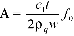

발명자들은 아래와 같이 근사치를 계산함으로써 적절하게 양호한 근사치가 얻어질 수 있음을 알아냈다:The inventors have found that a good approximation can be obtained as appropriate by calculating an approximation as follows:
![]()
![]()
그 결과로, 양호한 근사치까지, 주파수의 변화가 석영 수정 발진기가 노출되어 있는 가스의 밀도의 변화에 비례한다. 도 6은, 석영 수정 발진기(202)의 공진 주파수가 밀도의 함수로서 선형적으로 변하는, 다수의 상이한 가스들/가스 혼합물을 도시한다.As a result, up to a good approximation, the change in frequency is proportional to the change in the density of the gas to which the quartz crystal oscillator is exposed. Figure 6 shows a number of different gases / gas mixtures in which the resonant frequency of
일반적으로, 석영 수정 발진기(202)의 감도는 주파수의 5% 변화가, 예컨대, 대기 압력과 비교했을 때 250 bar에서의 산소 가스(32의 원자 질량수를 가짐)로 보여진다. 보통 대부분의 가스의 경우에 137 내지 450 bar g이고, 헬륨 및 수소에 대해서는 700 또는 900 bar g까지인, 그러한 압력 및 가스 밀도는 영구적 가스를 위해 이용되는 저장 실린더의 전형적인 것이다.In general, the sensitivity of the
석영 수정 발진기(202)는 상업적으로 공급되는 가스를 위한 밀도 센서로서 이용하기에 특히 적합하다. 가스의 밀도를 정확하게 감지하기 위해서는, 가스에 먼지 및 액적이 없을 필요가 있는데, 이는 상업적으로 공급되는 가스에서는 보장되지만, 공기에서는 또는 대부분의 압력 감시 상황에서는 보장되지 않는다.The
둘째로, 실린더 내의 가스 압력은 정상 이용[즉, 가스가 출구(110)를 통해 배출될 때에] 중에만 서서히 변화할 수 있기 때문에, 석영 수정 발진기(202)가 판독하는 데에 소량의 시간(대략 1 초)이 걸린다는 점은 측정의 정밀도에 영향을 미치지 않는다. 대략 1 초의 시간은 진동을 계수하는 필요성 및 석영 수정 발진기(202)가 새로운 가스 압력에서 평형에 도달해야 할 필요성 때문에 요구된다. Second, because the gas pressure in the cylinder may change only slowly during normal use (i.e., when the gas exits through the outlet 110), the
이 방법은 가스 실린더(100) 내의 가스가 균일하지 않으면, 예컨대 가스가 부분적으로 액체 충전된 실린더 내에서 발생할 수 있는 것과 같이 불균일한 혼합물이면 또는 최근에 준비되어 불충분하게 혼합된 가벼운 가스 및 무거운 가스인 경우에 덜 정확할 수 있다. 그러나, 이는 대부분의 패키징된 가스 용례에서 발생하는 것으로 보인다.This method can be used when the gas in the
전술한 바와 같이, 가스 실린더(100) 내에 가스의 내부 체적(V)은 일정하다. 따라서, 가스 실린더(100)의 내부 체적(V) 내에 가스의 밀도(ρ)가 센서 조립체(200)에 의한 측정값으로부터 얻어지면, 실린더 내에 가스의 질량(M)은 이하의 식으로부터 얻어질 수 있다. As described above, the internal volume V of the gas in the
![]()
![]()
따라서, 가스 밀도(ρ)의 직접적인 측정은 가스 실린더(100)에 남아 있는 가스의 질량의 계산을 가능하게 한다. Thus, direct measurement of the gas density (rho) allows calculation of the mass of gas remaining in the gas cylinder (100).
이 방식에서 가스 질량의 측정은 공지된 장치에 비해 다수의 이점을 갖는다. 예컨대, 본 발명의 실시예에 따라 측정된 질량은 온도에 대해 본질적으로 교정된다. 이와 달리, 예컨대 부르돈관 게이지를 이용하는 압력의 측정은 절대 온도에 비례하여 변동된다. 따라서, 본 장치는 공지된 장치에 의한 경우와 같이 온도 측정 및/또는 교정을 필요로 하지 않는다. The measurement of the gas mass in this manner has a number of advantages over known devices. For example, the measured mass in accordance with an embodiment of the present invention is essentially calibrated against temperature. Alternatively, for example, the measurement of the pressure using a Bourdon tube gauge varies in proportion to the absolute temperature. Thus, the device does not require temperature measurement and / or calibration as is the case with known devices.
또한, 본 발명의 실시예에 따라 측정된 가스의 질량은 본질적으로 압축성(Z)에 대해 교정된다. 예컨대 압력으로부터 가스 컨텐츠를 얻기 위하여 부르돈관 게이지를 이용하는 종래의 장치에서는, 가스의 압축성이 교정되어야 한다. 이는 압축성(Z)이 이상적인 가스에서 예상되는 방식으로 가스 압력에 비례하지 않는 고압에서 특히 중요하다. Further, the mass of the gas measured according to an embodiment of the present invention is essentially calibrated for compressibility (Z). For example, in a conventional device using a Bourdon tube gauge to obtain gas content from pressure, the compressibility of the gas must be calibrated. This is especially important at high pressures where compressibility (Z) is not proportional to the gas pressure in a manner expected in an ideal gas.
압축성에 대한 자동 보상이 도 7 및 도 8을 참조하여 예시되어 있다. 도 7은 아르곤, 산소 및 아르곤:이산화탄소 혼합물에 대한 압력(bar g)의 함수로서 Y축 상의 가스 질량(kg 단위)의 그래프를 도시한다. 도 7에 도시된 바와 같이, 상이한 가스들의 질량은 압력 증가에 따라 변동한다. 또한, 250 bar g를 초과하는 고압에서는, 질량과 압력 간에 더 이상 선형 관계가 존재하지 않는다. Automatic compensation for compressibility is illustrated with reference to Figures 7 and 8. Figure 7 shows a graph of gas mass (in kg) on the Y axis as a function of pressure (bar g) for argon, oxygen and argon: carbon dioxide mixtures. As shown in Fig. 7, the mass of the different gases fluctuates with increasing pressure. Also, at high pressures exceeding 250 bar g, there is no longer a linear relationship between mass and pressure.
도 8은 도 7과 동일한 3개의 가스(아르곤, 산소 및 아르곤:이산화탄소 혼합물)에 대한 밀도(kg/m3 단위)의 함수로서 Y축 상의 가스 질량(kg 단위)의 그래프를 도시한다. 도 7과 달리, 밀도의 함수로서 가스의 질량은 각 가스/가스 혼합물에 대해 동일하다는 것을 알 수 있다. 또한, 관계는 여전히 고압에서 선형이다. 따라서, 석영 수정 발진기(202)는 높은 해상도를 갖는 동시에 밀도와 고도로 선형일 수 있다.Shows a graph of (carbon dioxide mixture of argon, oxygen and argon) Density (kg / m 3 Unit) gas mass (kg unit) on the Y-axis as a function of for the Fig. 8 is the same three gases and Fig. 7, it can be seen that the mass of the gas as a function of density is the same for each gas / gas mixture. Also, the relationship is still linear at high pressure. Thus, the
전술한 바와 같이, 본 발명의 구조는 ppm(parts per million)의 해상도로 매우 높은 정밀도까지 질량 측정이 가능하게 한다. (도 7 및 도 8에 예시된 바와 같이) 높은 밀도와 압력에서 석영 밀도 센서(202)의 선형 응답과 결합되면, 높은 정밀도는 H2 및 He 등의 매우 가벼운 가스가 정밀하게 측정되게 할 수 있다. As described above, the structure of the present invention enables mass measurement to very high precision with a resolution of parts per million (ppm). When combined with the linear response of the
가스 실린더(100) 내에서 정압의 측정 외에, 센서 조립체(200)는 가스 실린더(100) 내외로 질량 유동을 측정할 수 있다. 이는 가스 실린더(100)로부터의 가스의 사용률이 요구되고, 아마도 실린더가 비워지기 전에 남아 있는 시간을 계산하는 상황에 유용할 수 있다. 대안적으로 또는 추가적으로, 가스의 정확한 양을 관리하도록 질량 유량이 모니터될 수 있다.In addition to measuring the static pressure within the
대기압의 가스 밀도는 단지 1 g/리터 정도이고, 보통의 가스 이용률은 흔히 분당 수 리터 정도이다. 발명자들은 석영 수정 발진기(202)가 가스 실린더(100)에서 배출되는 가스의 질량 유량을 표시된 밀도 변화에 의해 측정되게 할 수 있도록 충분히 안정적이고 정밀하다는 것을 알았다. 질량 유량(![]()
![]()

여기서, V는 체적이고, △ρ는 시간 간격(△t)에 걸쳐서 지시된 밀도의 변화이다. 이 경우에, 센서 조립체(200)의 작동은 석영 수정 발진기(202)의 다수의 진동 사이클을 적분하도록 구동 회로(204)를 필요로 한다. 따라서, 시간에 따른 순간적인 밀도의 변화율(![]()
![]()
도 9 및 도 10은 질량 유량 검출의 경험 데이터를 예시한다. 도 9는 표시된 ~100 bar 압력에서 50 리터 실린더로부터 분당 12 리터의 유량 동안에 X축 상의 시간(분 단위)의 함수로서 Y축 상의 주파수(kHz)의 그래프를 도시한다. 도 10은 ~100 bar 압력에서 50 리터 실린더에 대해 X축 상의 시간(분 단위)의 함수로서 Y축 상의 계산된 유량(분당 리터)의 그래프를 도시한다. Figures 9 and 10 illustrate empirical data of mass flow detection. Figure 9 shows a graph of the frequency on the Y-axis (kHz) as a function of time on the X-axis (in minutes) during a flow rate of 12 liters per minute from a 50 liter cylinder at a pressure of ~ 100 bar indicated. 10 shows a graph of calculated flow rate (liters per minute) on the Y axis as a function of time on the X axis (in minutes) for a 50 liter cylinder at ~ 100 bar pressure.
이들 도면은 대부분의 정상 이용 동안에, 가스 실린더(100)로부터 가스의 질량 유량이 시간에 따른 밀도의 변화의 측정값으로부터 결정될 수 있다는 것을 예시한다. 따라서, 질량 유량은 석영 수정 발진기(202)와 구동 회로(204)를 이용하여 충분한 정확도와 시간 해상도로 계산될 수 있다. These figures illustrate that during most normal use, the mass flow rate of the gas from the
도 11은 본 발명의 작동을 도시하는 다른 경험 데이터를 예시한다. 도 11은 X축 상의 총 실린더 질량(kg 단위)의 함수로서 Y축 상의 주파수(kHz 단위)의 그래프를 도시한다. 알 수 있는 바와 같이, 그래프는 고도의 정밀도로 대략 선형이다. 그러므로, 도 11은 가스 실린더(100) 내에 가스의 질량이 석영 수정 발진기(202)에 의해 정확하게 측정될 수 있다는 것을 보여준다.Figure 11 illustrates other experience data illustrating the operation of the present invention. Fig. 11 shows a graph of the frequency (in kHz units) on the Y-axis as a function of the total cylinder mass on the X-axis (in kg). As can be seen, the graph is approximately linear with high precision. Therefore, Fig. 11 shows that the mass of gas in the
이하, 도 12를 참조하여, 본 발명의 실시예에 따른 방법에 대해 설명한다. 아래에 기술된 방법은 도 2와 도 3을 참조하여 전술한 제1 실시예 및 제2 실시예 모두에 적용될 수 있다.
Hereinafter, a method according to an embodiment of the present invention will be described with reference to FIG. The method described below can be applied to both the first embodiment and the second embodiment described above with reference to Figs. 2 and 3. Fig.
단계 300: 측정의 초기화Step 300: Initialize the measurement
단계 300에서, 가스 실린더(100) 내에 가스의 질량의 측정이 초기화된다. 이는, 예컨대, 유저가 가스 실린더(100)의 외측에 있는 버튼을 누름으로써 작동될 수 있다. 대안적으로, 측정은 원격 연결, 예컨대, 무선 통신망을 통해 전송되고 안테나(250; 도 3 참조)를 통해 센서 조립체(200)에 의해 수신되는 신호에 의해 개시될 수 있다.In
다른 변경예 또는 추가예로서, 센서 조립체(200)는 원격으로 또는 타이머에 의해 초기화하도록 구성될 수 있다. 방법은 단계 302로 진행한다.
As another or additional example, the
단계 302: 석영 수정 발진기를 구동Step 302: driving a quartz crystal oscillator
초기화되면, 구동 회로(204)는 석영 수정 발진기(202)를 구동하도록 이용된다. 초기화 동안, 구동 회로(204)는 수정 발진기(202)를 가로질러 무작위 노이즈 AC 전압을 인가한다. 그 무작위 전압의 적어도 일부는 수정 발진기(202)가 진동하게 하기에 적합한 주파수에 있다. 그 후, 수정 발진기(202)은 그 신호와 동기하여 진동하기 시작한다.Once initialized, the
압전 효과에 의해, 석영 수정 발진기(202)의 동작이 석영 수정 발진기(202)의 공진 주파수 대역에서 전압을 발생시킨다. 그 후, 구동 회로(204)는, 석영 수정 공진기(202)의 주파수 대역에서 발생된 신호가 구동 회로(204)의 출력을 지배하도록, 석영 수정 발진기(202)에 의해 발생된 신호를 증폭시킨다. 석영 수정 필터의 좁은 공진 대역은 모든 원하지 않는 주파수를 필터링하고, 그 후, 구동 회로(204)는 기준 공진 주파수(f)에서 석영 수정 발진기(202)를 구동한다. 석영 수정 발진기(202)가 특정한 공진 주파수에서 안정화되면, 방법은 단계 304로 진행한다.
Due to the piezoelectric effect, the operation of the
단계 304: 석영 수정 발진기의 공진 주파수 측정Step 304: Measurement of resonance frequency of quartz crystal oscillator
공진 주파수(f)는 가스 실린더의 내부 체적(V) 내에 조건에 따라 좌우된다. 본 실시예에서, 공진 주파수의 변화(Δf)는, 가스 실린더(100) 내에 가스 밀도의 변화에 대해 크기가 비례하고 밀도가 증가하면 감소할 것이다.The resonance frequency f is dependent on the condition in the internal volume V of the gas cylinder. In this embodiment, the change in the resonance frequency? F will be proportional to the change in gas density in the
측정을 하기 위해서는, 석영 수정 발진기(202)의 주파수가 대략적으로 1초의 기간 동안 측정된다. 이는 판독이 안정화될 수 있게 하고, 정확한 측정을 결정하도록 충분한 진동이 계수되게 한다. 주파수의 측정은 프로세서(220)에서 수행된다. 프로세서(220)는 또한 측정이 시작될 때에 시간(T1)을 기록(log)할 수 있다.In order to perform the measurement, the frequency of the
주파수가 측정되었으면, 방법은 단계 306으로 진행한다.
If the frequency has been measured, the method proceeds to step 306.
단계 306: 가스 실린더 내에 가스의 질량 결정Step 306: Determine the mass of the gas in the gas cylinder
석영 수정 발진기(202)의 주파수가 단계 303에서 만족스럽게 측정되었다면, 프로세서(220)는 가스 실린더(100) 내에 가스의 질량을 계산한다.If the frequency of the
이는 가스의 질량이 단계 304에서 결정된 밀도와 가스 실린더(100)의 공지된 내부 체적(V)으로서 직접 계산될 수 있는 상기 수학식 5를 이용하여 행해진다. 이어서, 방법은 단계 308로 진행한다.
This is done using equation (5) above, in which the mass of the gas can be directly calculated as the density determined in
단계 308: 측정 결과의 저장Step 308: Storage of measurement results
가스의 질량이 계산되었다면, 질량은 나중의 검색을 위해 센서 조립체(200)의 프로세서(220)와 관련된 내부 메모리에 간단하게 기록될 수 있다. 또 다른 변경예로서, 시간(T1)에서의 가스의 질량은 상기 프로세서(220)에 대한 로컬 메모리에 저장될 수 있다. If the mass of the gas is calculated, the mass can simply be recorded in an internal memory associated with the processor 220 of the
이어서, 방법은 단계 310으로 진행한다.
The method then proceeds to step 310.
단계 310: 결과 전달Step 310: Transfer the Results
선택적인 단계로서, 가스의 질량은 다수의 방식으로 디스플레이될 수 있다. 예컨대, 가스 실린더(100) 또는 밸브(104)에 대해 부착된 스크린이 가스 실린더(100) 내에 수용된 가스의 질량을 디스플레이할 수 있다. 변경예에서, 가스 질량 측정값은 기지국에 대해 또는 인접한 피팅 상에 배치된 계기에 전달될 수 있다.As an optional step, the mass of the gas can be displayed in a number of ways. For example, a screen attached to the
이어서, 방법은 단계 312로 진행한다.
The method then proceeds to step 312.
단계 312: 센서 조립체의 파워 다운Step 312: Power down the sensor assembly
센서 조립체(200)를 항상 작동 상태로 유지할 필요는 없다. 이와 달리, 사용하지 않을 때에 센서 조립체(200)를 스위치 오프함으로써 전력 소비를 절감하는 것이 유리하다. 이는 배터리(206)의 수명을 연장시킨다. It is not necessary to keep the
구동 회로(204)의 구성은 석영 수정 발진기(202)가 가스 실린더(100) 내의 가스 압력에 상관없이 재시작되게 할 수 있다. 따라서, 센서 조립체(200)는 배터리 전력을 절약하기 위해 필요할 때에 정지될 수 있다. The configuration of the
본 발명의 실시예의 작동 방법은 상기 단계 300 내지 310을 참조하여 설명되었다. 그러나, 이하의 추가 단계가 또한 선택적으로 이루어질 수 있다.
The operation method of the embodiment of the present invention has been described with reference to
단계 314-318: 질량의 추가 결정Steps 314-318: Additional determination of mass
가스 실린더(100) 내외로 가스의 질량 유량을 계산하는 것이 요망될 수 있다. T1보다 나중인 시간(T2)에서, 단계 314, 316 및 318이 수행된다. 단계 314, 316 및 318은 시간(T2)에서 각각 수행된 단계 304, 306 및 308에 대응한다. 단계 314, 316 및 318로부터의 결과적인 값이 시간(T2)에서의 가스의 질량으로서 프로세서(220)의 내부 메모리에 저장된다. It may be desirable to calculate the mass flow rate of the gas into and out of the
T1과 T2 간의 시간 간격은 도 9에 의해 예시된 바와 같이 수 초 정도로 매우 짧을 수 있다. 대안적으로, 유량이 느리면, 또는 예컨대 누출로 인한 가스 실린더(100) 내의 손실을 측정하는 것이 요망되면, T1과 T2 간의 시간 간격은 예컨대 수 분, 수 시간 또는 수 일 정도로 상당히 커질 수 있다. The time interval between T 1 and T 2 can be very short, as illustrated by FIG. 9, on the order of a few seconds. Alternatively, if the flow rate is slow, or if it is desired, for example, to measure the loss in the
이어서, 방법은 단계 320로 진행한다.
The method then proceeds to step 320.
단계 320: 질량 유량의 계산Step 320: Calculation of mass flow rate
시간(T1과 T2) 간의 시간차와, 이들 시간에 가스 실린더(100) 내에 가스의 질량을 알면, 프로세서(220)는 수학식 6으로부터 T1과 T2 간의 시간 간격에 질량 유량을 계산할 수 있다. Knowing the time difference between the times T 1 and T 2 and the mass of the gas in the
이어서, 방법은 필요하다면 추가의 질량 유량을 계산하도록 단계 314 내지 320을 반복 수행할 수 있다. 대안적으로, 방법은 단계 312로 이동할 수 있고 센서 조립체(200)는 파워 다운될 수 있다. The method may then repeat steps 314-320 to calculate additional mass flow rates, if desired. Alternatively, the method may move to step 312 and the
상기 실시예들의 변경예가 당업자에게 명백할 것이다. 하드웨어 및 소프트웨어 구성요소들의 정확한 구성은 상이할 수 있으나 여전히 본 발명의 범위 내에 속한다. 당업자라면 이용될 수 있는 대안적 구성들을 쉽게 알아낼 것이다.Modifications of the above embodiments will be apparent to those skilled in the art. The exact configuration of the hardware and software components may vary but still fall within the scope of the present invention. Those skilled in the art will readily recognize alternative configurations that may be utilized.
예컨대, 전술한 실시예들은 기본 주파수가 32.768 kHz인 석영 수정 발진기를 활용한다. 그러나, 대안적인 주파수에서 작동하는 수정이 이용될 수 있다. 예컨대, 60 kHz 및 100 kHz에서 작동하는 석영 수정 발진기들이 전술한 실시예들에 사용될 수 있다. 도 13에는 여러 수정들을 위한 밀도에 따른 주파수 변화를 나타내는 그래프가 도시되어 있다. 다른 예로서, 1.8 MHz의 주파수에서 작동하는 수정 발진기가 이용될 수 있다.For example, the embodiments described above utilize a quartz crystal oscillator with a fundamental frequency of 32.768 kHz. However, modifications operating at alternative frequencies may be used. For example, quartz crystal oscillators operating at 60 kHz and 100 kHz may be used in the embodiments described above. FIG. 13 is a graph showing the frequency variation according to density for various modifications. As another example, a crystal oscillator operating at a frequency of 1.8 MHz may be used.
더 높은 주파수 작동은 주어진 횟수의 사이클을 샘플링하는 데에 더 짧은 시간이 요구되기 때문에, 압력이 더 빈번하게 모니터링되게 할 수 있다. 또한, 더 높은 주파수의 수정은 수정의 "슬립(sleep)" 모드에서 더 작은 듀티 사이클(duty cycle)이 이용되게 할 수 있다. 설명으로서, 대부분의 경우에, 수정 및 구동 회로는 스위치 오프된 상태로 대부분의 시간을 소비하고, 단지 잠시 동안만 또는 측정이 요구될 때에만 스위치 온된다. 이것은, 예컨대, 분 당 한번 일어날 수 있다. 더 높은 주파수의 수정이 이용되면, 압력이 더 빨리 측정될 수 있다. 그러므로, 수정이 작동 상태에 있는 시간이 감소될 수 있다. 이것은 전력 소비를 절감하고 부수적으로 배터리 수명을 향상시킬 수 있다.Higher frequency operation may allow pressure to be monitored more frequently since a shorter time is required to sample a given number of cycles. In addition, a higher frequency modification may cause a smaller duty cycle to be utilized in a "sleep" mode of correction. For clarity, in most cases, the correction and drive circuitry consumes most of the time in the switched-off state, and is switched on only for a short time or only when measurement is required. This can occur, for example, once per minute. If a higher frequency correction is used, the pressure can be measured more quickly. Therefore, the time during which the correction is in the operating state can be reduced. This can reduce power consumption and, incidentally, improve battery life.
또한, 상기 실시예들은 석영 수정 발진기의 절대 주파수를 측정하는 것에 의해 설명되었다. 그러나, 가스 실린더 관련 레귤레이터에 통합된 자족적 전자 기기(self-contained electronics)에서는, 그 주파수를 진공 또는 압력 패키지 속에 들어 있지만 동일한 유형의 기준 수정과 비교함으로써 센서의 주파수의 변위를 측정하는 것이 유리할 수 있다. 압력 패키지는 선택된 밀도의 가스, 대기 조건 하에 있는 가스를 포함할 수 있거나 또는 가스 실린더(100) 외부의 대기로 개방될 수 있다.In addition, the above embodiments have been described by measuring the absolute frequency of a quartz crystal oscillator. However, in self-contained electronics integrated in gas-cylinder related regulators, it may be advantageous to measure the frequency displacement of the sensor by comparing the frequency with a reference modification of the same type, which is in a vacuum or pressure package have. The pressure package may include a selected density of gas, a gas under atmospheric conditions, or may be open to atmosphere outside the
적합한 센서 조립체(400)가 도 14에 도시되어 있다. 센서 조립체(400)는 제1 석영 수정 발진기(402) 및 제2 석영 수정 발진기(404)를 포함한다. 제1 석영 수정 발진기(402)는 진공 하에 밀봉된 컨테이너(406) 내에 배치되는 기준 수정이다. 제1 석영 수정 발진기(402)는 구동 회로(408)에 의해 구동된다.A
제2 석영 수정 발진기(404)는 이전의 실시예들에서 설명된 수정(202)과 유사한 수정이다. 제2 석영 수정 발진기(404)는 가스 실린더(100)의 내부 체적 내에 가스 환경에 노출된다. 제2 석영 수정 발진기(404)는 구동 회로(410)에 의해 구동된다.The second
이 비교는 2개의 주파수 신호를 조합하고 2개의 수정들 사이의 차이에 동등한 주파수에서 출력을 생성하는 전자 혼합기 회로(414)를 이용하여 수행될 수 있다. 이 구조는, 예컨대, 온도로 인한 작은 변화가 무효가 되게 할 수 있다.This comparison may be performed using an electronic mixer circuit 414 that combines the two frequency signals and produces an output at a frequency that is equal to the difference between the two modifications. This structure can, for example, make small changes due to temperature invalid.
또한, 주파수 차이만 측정될 것이 요구되기 때문에, 가스 실린더(100)에서 이용되는 회로가 단순화될 수 있다. 또한, 이 접근 방안은, 수정 주파수를 직접적으로 측정하는 것이 곤란할 수 있는 곳에서, 고 주파수(MHz) 수정 발진기에 사용하는 데에 특히 적합하다.In addition, since it is required that only the frequency difference be measured, the circuit used in the
또한, 밀도, 질량 또는 질량 유량을 측정하고 표시하기 위해 요구되는 모든 전자 기기는 가스 실린더 상에 또는 내부에 장착될 필요가 없다. 예컨대, 실린더 상에 영구적으로 장착된 유닛과, 고객의 사용 위치에 따라 장착되거나 종래의 유량계에 대해 보통 이용되는 위치와 같은 실린더의 출구 상에 일시적으로 장착되는 유닛 간에, 전자 기능들이 분할될 수 있다.In addition, not all electronic devices required to measure and display density, mass, or mass flow rate need to be mounted on or in the gas cylinder. For example, electronic functions may be divided between a unit permanently mounted on a cylinder and a unit mounted temporarily on the outlet of a cylinder, such as a location mounted on or customarily used for a conventional flow meter, depending on the customer's location of use .
도 15를 참조하면, 이 장치의 한 예가 도시되어 있다. 장치는, 가스 실린더(500)와 센서 조립체(502)를 포함하는 가스 실린더 조립체(50)를 포함한다. 가스 실린더 조립체(50), 가스 실린더(500) 및 센서 조립체(502)는, 이전 실시예들을 참조하여 이미 설명된 가스 실린더 조립체(10), 가스 실린더(100) 및 센서 조립체(200)와 실질적으로 유사하다. Referring to Fig. 15, an example of this device is shown. The apparatus includes a gas cylinder assembly (50) including a gas cylinder (500) and a sensor assembly (502). The
본 실시예에서, 센서 조립체(502)는 이전 실시예들의 석영 수정 발진기(202) 및 구동 회로(204)와 유사한 석영 수정 발진기 및 구동 회로(도시 생략)를 포함한다. 임의의 적절한 원격 통신 프로토콜, 예컨대 블루투스, 적외선(IR) 또는 RFID를 통한 통신을 위해 안테나(504)가 제공된다. 대안적으로, 단선 통신(one-wire communication)이 활용될 수 있다.In this embodiment, the
다른 대안으로서, 음향 통신 방법이 이용될 수 있다. 그러한 방법의 이점은 외부 안테나(250)에 대한 요구 없이 원격 통신이 실시될 수 있다는 것이다.As an alternative, an acoustic communication method may be used. An advantage of such a method is that remote communication can be carried out without the need for an
연결 파이프(506)가 가스 실린더(500)의 출구에 연결된다. 연결 파이프는 신속 접속 연결부(quick connect connection)(508)에 의해 종결된다. 신속 접속 연결부(508)는 접속용 배관 또는 구성요소들이 가스 실린더(500)와 용이하고 신속하게 접속 및 접속 해제될 수 있게 한다.A connecting
가스 실린더(500)에 대한 연결을 위해 신속 접속 유닛(550)이 제공된다. 커넥터(508)에 대한 연결을 위해, 상보적인 신속 접속 커넥터(510)가 제공된다. 또한, 신속 접속 유닛(550)에는 데이터 유닛(552)이 제공된다. 데이터 유닛(552)은 가스 실린더 조립체(50)의 안테나(504)와 통신하기 위한 안테나(556) 및 디스플레이(554)를 포함한다. 디스플레이(554)는, 전력 소비를 최소화하고 디스플레이의 가시도를 최대화하기 위해, 예컨대, E-잉크 디스플레이를 포함할 수 있다.A
데이터 유닛(552)은 가스 실린더 조립체(50)의 센서 조립체(502)에 의해 측정된 바와 같은 다양한 파라미터들을 기록할 수 있다. 예컨대, 데이터 유닛(552)은 유량 대 시간을 기록할 수 있다. 그러한 기록은, 예컨대, 중요한 구성요소들에 대한 장기간의 가스 용접 절차 동안 가스 유동이 있었고 올바른 것이었는지를 점검하기를 원하거나, 또는 데이터를 특정한 고객의 이용에 공급하기를 원하는 용접 계약자들에게 유용할 수 있다.The
또한, 가스 실린더(500)로부터 얻어진 데이터는 런아웃 시간, 즉 실린더(500) 내의 가스가 다 사용되기 전의 시간에 관한 데이터를 제공하도록 사용될 수 있다. 이는 병원들 간에 환자 운반에 사용되는 병원 산소 실린더 등의 용례에서 특히 중요하다. 그러한 시간(Tro)은 이하의 수학식을 통해 유량(전술함), 실린더(500)의 질량 컨텐츠 및 현재의 시간(Tc)의 인지로부터 계산될 수 있다.Further, the data obtained from the

대안적으로, 데이터 유닛(550)으로부터의 데이터는 경고 메시지와 함께 유도된 파라미터의 계산을 허용하도록 (용접 용례를 위한) 컴퓨터 인에이블드 용접 장치 또는 다른 가스 이용 장비로 출력될 수 있다. 그 예시적인 예로는, 단위 아크 시간 당 사용된 가스, 용접 와이어(예컨대, 용접의 기공률에 관한 경고를 갖는)의 kg 당 사용된 가스, 남아 있는 용접 시간, (공지된 가스 데이터를 이용하여 측정된 밀도값을 압력으로 전환시키는 것에 의한) 압력의 디스플레이일 수 있다. Alternatively, the data from
또한, 데이터 유닛(550)은 다음의 기능들, 즉, 가스 레벨이 특정한 레벨 또는 유량 아래에 있다면 청각 또는 시각 경보를 제공하고; (예컨대, 서서히 변화하는 혼합물을 위해) 실린더 수명 또는 실린더 만기날을 출력하며; 가스를 수용하고 가스 사용에 관한 데이터, 즉 어떤 유형의 용접인지, 어떤 유형의 금속이 용접되었는지를 디스플레이하거나, 모바일 폰 또는 컴퓨터가 상세한 데이터를 픽업할 수 있도록 링크를 제공하고; 다중 모드 작동, 예컨대 공급자/충전자 모드 및 고객 모드를 제공하고; 실린더를 재충전하는 가스 회사에 의해 디스플레이되는 고객에게 상이한 양을 디스플레이하며; 데이터의 입력을 허용하며; 실린더 번호, 가스의 타입, 분석 증명서, 고객 이력(누가 어떤 날에 실린더를 가졌는지), 안전 데이터 및 실린더에서 요약된 형태로 수행될 수 있는 작동 팁을 제공하도록 배치될 수 있다.The
대안적으로, 위의 모든 예는, 선택적으로 센서 조립체(200, 502)의 관점에서 논의된 바와 같이, 가스 실린더(500) 상에(또는 내에) 전체적으로 배치된 시스템으로부터, 처리, 저장 또는 얻어질 수 있다.Alternatively, all of the above examples may be processed, stored, or obtained from a system that is disposed entirely on (or within) the
추가적으로, 본 발명의 실시예는 누출 검출을 수행하도록 또한 사용될 수 있다. 석영 수정 발진기는 그러한 센서의 큰 감도로 인해 이 작업에 특히 적합하다. 또한, 석영 수정 발진기는 압력 게이지를 이용하여 누출을 감지할 때와 같이 실린더의 온도 변화로 인한 압력 변화를 부정확하게 판독하지 않게 된다. 또한, 본 발명의 실시예는 예컨대 (예를 들어, 3 bar g 미만의 압력으로 사용된 실린더에서) 잔류 압력 밸브 고장의 검출 시에 고장을 검출하도록 사용될 수 있다. Additionally, embodiments of the present invention may also be used to perform leak detection. Quartz crystal oscillators are particularly suitable for this task due to the high sensitivity of such sensors. In addition, the quartz crystal oscillator does not read the pressure change due to the temperature change of the cylinder incorrectly, such as when leaking using a pressure gauge. Embodiments of the present invention may also be used to detect faults upon detection of a residual pressure valve failure, for example (e.g., in a cylinder used at pressures less than 3 bar g).
상기 실시예들이 석영 수정 발진기의 이용을 참조하여 기술되었지만, 당업자는 또한 이용될 수 있는 대안적인 압전 재료들을 쉽게 인식할 것이다. 예컨대, 예시적인 목록은: 리튬 탄탈레이트, 리튬 니오베이트, 리튬 보레이트, 베를리나이트, 갈륨 비화물, 리튬 테트라보레이트, 인산 알루미늄, 비스무스 게르마늄 산화물, 다결정 지르코늄 티타네이트 세라믹스, 고 알루미나 세라믹스(high-alumina ceramics), 실리콘-아연 산화물 합성물, 또는 디포타슘 타르타르산염을 포함하는 수정 발진기를 포함할 수 있다.While the above embodiments have been described with reference to the use of a quartz crystal oscillator, those skilled in the art will also readily recognize alternative piezoelectric materials that may be utilized. For example, an exemplary list includes: lithium tantalate, lithium niobate, lithium borate, berlinite, gallium arsenide, lithium tetraborate, aluminum phosphate, bismuth germanium oxide, polycrystalline zirconium titanate ceramics, high- alumina ceramics, a silicon-zinc oxide composite, or a crystal oscillator including a dipotassium tartarate salt.
또한, 상기 실시예들을 가스 실린더를 참조하여 예시하였지만, 본 발명의 다른 용례가 사용될 수 있다. 예컨대, 석영 수정 발진기는 자동차, 모터바이크 또는 트럭 등의 차량의 타이어 내에 배치될 수 있다. 차량의 타이어의 형태가 부하 하에 또는 속도에서 변할 수 있지만, 본 출원의 발명자들은 타이어의 내부 체적이 사용시에 크게 변하지 않는다는 것을 알았다. 예컨대, 이 상황에서 내부 체적의 변화가 총 내부 체적의 2-3%보다 작다고 가정하면, 본 발명은 차량의 타이어 내에 가스의 질량을 계산하도록 신뢰성 있게 작동될 수 있다.Further, while the above embodiments have been illustrated with reference to gas cylinders, other applications of the present invention may be used. For example, quartz crystal oscillators can be placed in the tires of vehicles such as automobiles, motorbikes, or trucks. Although the shape of the tire of the vehicle may vary under load or at speed, the inventors of the present application have found that the internal volume of the tire does not change significantly during use. For example, assuming that the change in internal volume in this situation is less than 2-3% of the total internal volume, the present invention can be reliably operated to calculate the mass of gas in the tire of the vehicle.
또한, 많은 용례가 차량 타이어 내의 가스로서 공기를 사용하지만, 질소 등의 가스가 점차 사용된다. 본 발명의 장치는 특히 그러한 용례에 적합하다. 질량의 측정이 본질적으로 온도에 종속하기 때문에, 본 발명의 장치는 환경 조건이 측정에 영향을 미칠 수 있는 상황에 특히 유용하다.In addition, many applications use air as gas in vehicle tires, but gas such as nitrogen is gradually used. The apparatus of the present invention is particularly suitable for such an application. Since the measurement of mass is inherently temperature dependent, the device of the present invention is particularly useful in situations where environmental conditions can affect the measurement.
다른 예로서, 본 발명은 또한 차량용 공기 서스펜션 시스템에 적용될 수 있다. As another example, the present invention can also be applied to a vehicle air suspension system.
본 발명의 실시예들이 예시된 예에 대한 특정한 참조로 기술되었다. 특정한 예가 도면에 도시되고 여기에 상세히 설명되었지만, 도면 및 상세한 설명은 본 발명을 기술된 특정한 형태로 한정하려는 것이 아님을 알아야 한다. 본 발명의 범위 내에서 설명된 예에 대해 변화 및 수정이 이루어질 수 있을 것임을 알 것이다.Embodiments of the invention have been described with specific reference to illustrative examples. While specific examples have been illustrated in the drawings and have been described in detail herein, it should be understood that the drawings and detailed description are not intended to limit the invention to the particular forms disclosed. It will be appreciated that variations and modifications may be made to the examples described within the scope of the present invention.
Claims (15)
a)가스 실린더(100) 내에 가스의 밀도를 측정하도록 상기 압전 발진기(202)를 이용하는 단계;
b)밀도 측정값으로부터 그리고 상기 가스 실린더의 내부 체적(V)으로부터, 가스 실린더(100) 내에 가스의 질량을 결정하는 단계를 포함하는 것인 가스 질량 측정 방법.A method of measuring the mass of a gas under pressure using a piezoelectric oscillator (202), said gas comprising a gas cylinder (100) comprising a mixture of permanent gas or permanent gas and having a fixed internal volume (V) And the gas cylinder 100 is connected to the gas cylinder body 102 and is capable of selectively distributing the gas from the gas cylinder 100 or selectively filling the gas to the gas cylinder body 102 And a piezoelectric oscillator (202) arranged in the valve device (104) and immersed in gas in the gas cylinder (100) so as to be located inside the gas cylinder body (102) The method comprises:
a) using the piezoelectric oscillator (202) to measure the density of the gas in the gas cylinder (100);
b) determining the mass of the gas in the gas cylinder (100) from the density measurement and from the internal volume (V) of the gas cylinder.
상기 압전 발진기가 공진 주파수로 공진하도록 구동 회로에 의해 압전 발진기를 구동하는 단계와,
상기 가스 실린더 내에 가스의 밀도를 결정하도록 예정된 시간에 걸쳐 상기 공진 주파수를 측정하는 단계를 포함하는 것인 가스 질량 측정 방법.The method of claim 1, wherein step a)
Driving a piezoelectric oscillator by a drive circuit such that the piezoelectric oscillator resonates at a resonant frequency;
And measuring the resonant frequency over a predetermined time to determine the density of the gas in the gas cylinder.
Applications Claiming Priority (3)
| Application Number | Priority Date | Filing Date | Title |
|---|---|---|---|
| EP10192962.8A EP2458344B1 (en) | 2010-11-29 | 2010-11-29 | Method of, and apparatus for, measuring the true contents of a cylinder of gas under pressure |
| EP10192962.8 | 2010-11-29 | ||
| PCT/EP2011/071198 WO2012072588A1 (en) | 2010-11-29 | 2011-11-28 | Method of, and apparatus for, measuring the true contents of a cylinder of gas under pressure |
Publications (2)
| Publication Number | Publication Date |
|---|---|
| KR20130103582A KR20130103582A (en) | 2013-09-23 |
| KR101544291B1 true KR101544291B1 (en) | 2015-08-12 |
Family
ID=43827624
Family Applications (1)
| Application Number | Title | Priority Date | Filing Date |
|---|---|---|---|
| KR1020137017159A KR101544291B1 (en) | 2010-11-29 | 2011-11-28 | Method of, and apparatus for, measuring the true contents of a cylinder of gas under pressure |
Country Status (12)
| Country | Link |
|---|---|
| US (1) | US9255870B2 (en) |
| EP (1) | EP2458344B1 (en) |
| KR (1) | KR101544291B1 (en) |
| CN (1) | CN103608649B (en) |
| BR (1) | BR112013013326B1 (en) |
| CA (1) | CA2817794C (en) |
| CL (1) | CL2013001501A1 (en) |
| ES (1) | ES2671716T3 (en) |
| MX (1) | MX2013005952A (en) |
| PL (1) | PL2458344T3 (en) |
| TW (1) | TWI454700B (en) |
| WO (1) | WO2012072588A1 (en) |
Families Citing this family (22)
| Publication number | Priority date | Publication date | Assignee | Title |
|---|---|---|---|---|
| US9731593B2 (en) * | 2008-08-07 | 2017-08-15 | Ford Global Technologies, Llc | Fuel storage system |
| US20130180995A1 (en) * | 2009-12-21 | 2013-07-18 | Wika Alexander Wiegand Se & Co. Kg | Gas Cylinder with Measuring Connection |
| ES2888099T3 (en) * | 2013-09-13 | 2021-12-30 | Air Prod & Chem | Method and apparatus for monitoring the available resources of a gas cylinder |
| DE102014003342B4 (en) * | 2014-03-07 | 2017-10-19 | Astrium Gmbh | Cryogenic fuel tank with a measuring module |
| KR101636356B1 (en) * | 2014-05-30 | 2016-07-07 | 한국원자력연구원 | A gas collector using a chamber and a volumetric column and a gas collecting method thereof |
| US9534738B2 (en) * | 2014-10-24 | 2017-01-03 | Quantum Fuel Systems Llc | Composite pressure tank identification and tracking |
| CN104460435B (en) * | 2014-11-12 | 2017-04-12 | 杨晓东 | Intelligent remote monitoring system of liquid gas storage tank |
| CN106370224A (en) * | 2015-07-21 | 2017-02-01 | 昱晶能源科技股份有限公司 | Testing system and testing method thereof |
| KR102163468B1 (en) * | 2016-06-13 | 2020-10-08 | 주식회사 엘지화학 | Device for Quantitative Analysis of Deposited Metal |
| KR102284628B1 (en) * | 2016-07-27 | 2021-08-02 | 뷔흘러 에이지 | Electromechanical actuators for bulk material blocking elements |
| WO2018217956A1 (en) | 2017-05-23 | 2018-11-29 | Michigan Scientific Corporation | Electro acoustic volume measurement |
| CN107588884A (en) * | 2017-08-08 | 2018-01-16 | 中国石油天然气集团公司 | One kind is with brill down-hole pressure measuring circuit and pressure measurement method |
| CN108758329A (en) * | 2018-06-19 | 2018-11-06 | 沈阳科汇生产力促进中心有限公司 | Filling machine, aerating statistical method, tax control filling machine and aerating tax control method |
| CN109084856B (en) * | 2018-07-19 | 2021-06-04 | 中国神华能源股份有限公司 | Flow measuring method for open circulating water system |
| US10928287B2 (en) | 2018-08-09 | 2021-02-23 | Air Products And Chemicals, Inc | Method and apparatus for using a gas density sensor to measure and control gas mixture composition |
| RU2689284C1 (en) * | 2018-11-08 | 2019-05-24 | Общество с ограниченной ответственностью "Газпром добыча Уренгой" | Method for measuring medium density |
| WO2020204922A1 (en) * | 2019-04-03 | 2020-10-08 | Micro Motion, Inc. | Using vapor pressure to determine concentrations of components in a multi-component fluid |
| DE102020005590A1 (en) * | 2020-09-12 | 2022-03-17 | Messer Gaspack Gmbh | Arrangement for storing gas |
| CN112556774B (en) * | 2020-11-27 | 2023-01-31 | 国网安徽省电力有限公司电力科学研究院 | Gradient inflatable SF based on weighing method 6 Method for measuring volume of gas chamber |
| WO2023287506A1 (en) * | 2021-07-14 | 2023-01-19 | Hexagon Technology As | Compressed gas cylinder gas density measurement |
| CN113720427B (en) * | 2021-08-10 | 2024-08-30 | 国网山东省电力公司电力科学研究院 | Sulfur hexafluoride gas life cycle management system and method based on RFID |
| US20240044738A1 (en) | 2022-08-04 | 2024-02-08 | Air Products And Chemicals, Inc. | Compressed fluid vessel monitoring apparatus and method |
Citations (1)
| Publication number | Priority date | Publication date | Assignee | Title |
|---|---|---|---|---|
| US20060142954A1 (en) * | 2002-07-26 | 2006-06-29 | Endress + Hauser Gmbh + Co. Kg | Device for the determination or monitoring of a physical or chemical process parameter |
Family Cites Families (15)
| Publication number | Priority date | Publication date | Assignee | Title |
|---|---|---|---|---|
| DE1598084C3 (en) * | 1965-12-21 | 1974-02-21 | Basf Ag, 6700 Ludwigshafen | Device for the continuous determination of the specific gravity of flowable substances |
| US4644796A (en) | 1983-06-21 | 1987-02-24 | Quartztronics, Inc. | Pressure measurement apparatus and method |
| DE4218926A1 (en) * | 1992-06-10 | 1993-12-16 | Asea Brown Boveri | Device for measuring a gas density |
| US5455475A (en) * | 1993-11-01 | 1995-10-03 | Marquette University | Piezoelectric resonant sensor using the acoustoelectric effect |
| IL121316A (en) * | 1997-07-15 | 2001-07-24 | Litana Ltd | Implantable medical device of shape memory alloy |
| WO1999040553A1 (en) * | 1998-02-05 | 1999-08-12 | Wan Tae Kim | Alarm device for sensing gas quantity within pressure vessel |
| US6050598A (en) * | 1998-10-02 | 2000-04-18 | Trw Inc. | Apparatus for and method of monitoring the mass quantity and density of a fluid in a closed container, and a vehicular air bag system incorporating such apparatus |
| US6465749B1 (en) * | 2000-07-07 | 2002-10-15 | Los Robles Advertising, Inc. | Magnetostrictive mass sensing apparatus and method |
| DE10232823B4 (en) * | 2002-04-29 | 2004-08-12 | Hydrotechnik Gmbh | Density monitor for SF6-insulated high or medium voltage systems |
| JP4432990B2 (en) * | 2007-03-22 | 2010-03-17 | セイコーエプソン株式会社 | Sensor and electronic equipment |
| ATE512358T1 (en) * | 2009-04-29 | 2011-06-15 | Nest Int Nv | DEVICE FOR MEASURING LIQUID DENSITY |
| EP2458377B1 (en) * | 2010-11-29 | 2019-07-31 | Air Products And Chemicals, Inc. | Method of, and apparatus for, measuring the molecular weight of a gas |
| ES2536091T3 (en) * | 2012-05-24 | 2015-05-20 | Air Products And Chemicals, Inc. | Apparatus for measuring the true content of a gas cylinder under pressure |
| EP2667276B1 (en) * | 2012-05-24 | 2017-11-08 | Air Products And Chemicals, Inc. | Method of, and apparatus for, providing a gas mixture |
| PL2667162T3 (en) * | 2012-05-24 | 2016-03-31 | Air Prod & Chem | Method of, and apparatus for, measuring the physical properties of two-phase fluids |
-
2010
- 2010-11-29 ES ES10192962.8T patent/ES2671716T3/en active Active
- 2010-11-29 EP EP10192962.8A patent/EP2458344B1/en active Active
- 2010-11-29 PL PL10192962T patent/PL2458344T3/en unknown
-
2011
- 2011-11-24 TW TW100143188A patent/TWI454700B/en active
- 2011-11-28 KR KR1020137017159A patent/KR101544291B1/en active IP Right Grant
- 2011-11-28 WO PCT/EP2011/071198 patent/WO2012072588A1/en active Application Filing
- 2011-11-28 MX MX2013005952A patent/MX2013005952A/en active IP Right Grant
- 2011-11-28 CN CN201180066213.9A patent/CN103608649B/en active Active
- 2011-11-28 BR BR112013013326-0A patent/BR112013013326B1/en active IP Right Grant
- 2011-11-28 US US13/989,212 patent/US9255870B2/en active Active
- 2011-11-28 CA CA2817794A patent/CA2817794C/en active Active
-
2013
- 2013-05-27 CL CL2013001501A patent/CL2013001501A1/en unknown
Patent Citations (1)
| Publication number | Priority date | Publication date | Assignee | Title |
|---|---|---|---|---|
| US20060142954A1 (en) * | 2002-07-26 | 2006-06-29 | Endress + Hauser Gmbh + Co. Kg | Device for the determination or monitoring of a physical or chemical process parameter |
Also Published As
| Publication number | Publication date |
|---|---|
| CN103608649A (en) | 2014-02-26 |
| EP2458344B1 (en) | 2018-03-14 |
| WO2012072588A1 (en) | 2012-06-07 |
| PL2458344T3 (en) | 2018-08-31 |
| BR112013013326A2 (en) | 2018-05-08 |
| TW201229513A (en) | 2012-07-16 |
| ES2671716T3 (en) | 2018-06-08 |
| CN103608649B (en) | 2018-04-17 |
| TWI454700B (en) | 2014-10-01 |
| CL2013001501A1 (en) | 2014-03-28 |
| KR20130103582A (en) | 2013-09-23 |
| BR112013013326B1 (en) | 2021-02-17 |
| MX2013005952A (en) | 2013-07-03 |
| US9255870B2 (en) | 2016-02-09 |
| CA2817794C (en) | 2016-01-12 |
| EP2458344A1 (en) | 2012-05-30 |
| CA2817794A1 (en) | 2012-06-07 |
| US20130306650A1 (en) | 2013-11-21 |
Similar Documents
| Publication | Publication Date | Title |
|---|---|---|
| KR101544291B1 (en) | Method of, and apparatus for, measuring the true contents of a cylinder of gas under pressure | |
| US9581297B2 (en) | Method of, and apparatus for, measuring the true contents of a cylinder of gas under pressure | |
| KR101659200B1 (en) | Method ofand apparatus forproviding a gas mixture | |
| KR101486831B1 (en) | Method of, and apparatus for, measuring the pressure of a gas | |
| KR101480370B1 (en) | Method of, and apparatus for, measuring the mass flow rate of a gas | |
| KR101761991B1 (en) | Method of,and apparatus for,providing a gas mixture | |
| KR101741872B1 (en) | Method of, and apparatus for, measuring the molecular weight of a gas | |
| JP6408587B2 (en) | Method and apparatus for monitoring the available supply of a gas cylinder |
Legal Events
| Date | Code | Title | Description |
|---|---|---|---|
| A201 | Request for examination | ||
| E902 | Notification of reason for refusal | ||
| E701 | Decision to grant or registration of patent right | ||
| GRNT | Written decision to grant | ||
| FPAY | Annual fee payment |
Payment date: 20180628 Year of fee payment: 4 |
|
| FPAY | Annual fee payment |
Payment date: 20190624 Year of fee payment: 5 |