KR101507867B1 - Network communication method and terminal in a heterogeneous network environment - Google Patents
Network communication method and terminal in a heterogeneous network environment Download PDFInfo
- Publication number
- KR101507867B1 KR101507867B1 KR20137031838A KR20137031838A KR101507867B1 KR 101507867 B1 KR101507867 B1 KR 101507867B1 KR 20137031838 A KR20137031838 A KR 20137031838A KR 20137031838 A KR20137031838 A KR 20137031838A KR 101507867 B1 KR101507867 B1 KR 101507867B1
- Authority
- KR
- South Korea
- Prior art keywords
- terminal
- message
- base station
- heterogeneous
- wlan
- Prior art date
Links
- 238000004891 communication Methods 0.000 title claims abstract description 116
- 238000000034 method Methods 0.000 title claims abstract description 41
- 238000010295 mobile communication Methods 0.000 claims abstract description 23
- 238000005516 engineering process Methods 0.000 claims abstract description 18
- 238000010586 diagram Methods 0.000 description 25
- 230000005540 biological transmission Effects 0.000 description 23
- 238000007726 management method Methods 0.000 description 12
- VYLDEYYOISNGST-UHFFFAOYSA-N bissulfosuccinimidyl suberate Chemical compound O=C1C(S(=O)(=O)O)CC(=O)N1OC(=O)CCCCCCC(=O)ON1C(=O)C(S(O)(=O)=O)CC1=O VYLDEYYOISNGST-UHFFFAOYSA-N 0.000 description 11
- 230000015654 memory Effects 0.000 description 11
- 238000013468 resource allocation Methods 0.000 description 10
- 239000008186 active pharmaceutical agent Substances 0.000 description 9
- 230000008569 process Effects 0.000 description 7
- 230000002776 aggregation Effects 0.000 description 6
- 238000004220 aggregation Methods 0.000 description 6
- 230000006870 function Effects 0.000 description 6
- 101000741965 Homo sapiens Inactive tyrosine-protein kinase PRAG1 Proteins 0.000 description 5
- 102100038659 Inactive tyrosine-protein kinase PRAG1 Human genes 0.000 description 5
- 239000000969 carrier Substances 0.000 description 3
- 230000008859 change Effects 0.000 description 3
- 230000011664 signaling Effects 0.000 description 3
- 101100172132 Mus musculus Eif3a gene Proteins 0.000 description 2
- 238000001994 activation Methods 0.000 description 2
- 230000001413 cellular effect Effects 0.000 description 2
- 125000004122 cyclic group Chemical group 0.000 description 2
- 230000001419 dependent effect Effects 0.000 description 2
- 230000007774 longterm Effects 0.000 description 2
- 238000013507 mapping Methods 0.000 description 2
- 101100165205 Caenorhabditis elegans bbs-2 gene Proteins 0.000 description 1
- 230000003213 activating effect Effects 0.000 description 1
- 230000004913 activation Effects 0.000 description 1
- 238000004880 explosion Methods 0.000 description 1
- 239000012634 fragment Substances 0.000 description 1
- 230000010354 integration Effects 0.000 description 1
- 230000002452 interceptive effect Effects 0.000 description 1
- 238000013439 planning Methods 0.000 description 1
- 230000004044 response Effects 0.000 description 1
- 238000005070 sampling Methods 0.000 description 1
- 230000001502 supplementing effect Effects 0.000 description 1
Images


Classifications
-
- H—ELECTRICITY
- H04—ELECTRIC COMMUNICATION TECHNIQUE
- H04W—WIRELESS COMMUNICATION NETWORKS
- H04W72/00—Local resource management
- H04W72/12—Wireless traffic scheduling
- H04W72/1215—Wireless traffic scheduling for collaboration of different radio technologies
-
- H—ELECTRICITY
- H04—ELECTRIC COMMUNICATION TECHNIQUE
- H04W—WIRELESS COMMUNICATION NETWORKS
- H04W72/00—Local resource management
- H04W72/04—Wireless resource allocation
-
- H—ELECTRICITY
- H04—ELECTRIC COMMUNICATION TECHNIQUE
- H04L—TRANSMISSION OF DIGITAL INFORMATION, e.g. TELEGRAPHIC COMMUNICATION
- H04L5/00—Arrangements affording multiple use of the transmission path
- H04L5/003—Arrangements for allocating sub-channels of the transmission path
- H04L5/0037—Inter-user or inter-terminal allocation
-
- H—ELECTRICITY
- H04—ELECTRIC COMMUNICATION TECHNIQUE
- H04W—WIRELESS COMMUNICATION NETWORKS
- H04W74/00—Wireless channel access
- H04W74/08—Non-scheduled access, e.g. ALOHA
-
- H—ELECTRICITY
- H04—ELECTRIC COMMUNICATION TECHNIQUE
- H04W—WIRELESS COMMUNICATION NETWORKS
- H04W74/00—Wireless channel access
- H04W74/08—Non-scheduled access, e.g. ALOHA
- H04W74/0808—Non-scheduled access, e.g. ALOHA using carrier sensing, e.g. carrier sense multiple access [CSMA]
- H04W74/0816—Non-scheduled access, e.g. ALOHA using carrier sensing, e.g. carrier sense multiple access [CSMA] with collision avoidance
-
- H—ELECTRICITY
- H04—ELECTRIC COMMUNICATION TECHNIQUE
- H04W—WIRELESS COMMUNICATION NETWORKS
- H04W16/00—Network planning, e.g. coverage or traffic planning tools; Network deployment, e.g. resource partitioning or cells structures
- H04W16/14—Spectrum sharing arrangements between different networks
Landscapes
- Engineering & Computer Science (AREA)
- Signal Processing (AREA)
- Computer Networks & Wireless Communication (AREA)
- Mobile Radio Communication Systems (AREA)
Abstract
본 명세서는, 동일한 주파수 대역을 사용하는 이종 네트워크 환경에서의 통신 방법으로서, 송신국이 이종의 통신 기술을 이용하는 기지국 또는 이종의 단말로 상기 주파수 대역 내의 임의의 채널을 사용하기 위한 메시지를 송신하는 단계; 및 상기 송신국이 상기 임의의 채널을 사용하여 수신국과 데이터 통신을 수행하는 단계를 포함하되, 상기 메시지는, 상기 송신국이 상기 데이터 통신을 위해 상기 임의의 채널을 사용할 시간을 포함하고, 상기 메시지는, 상기 시간 동안 상기 메시지를 수신한 상기 이종의 기지국 또는 이종의 단말이 상기 임의의 채널을 사용하는 데이터 통신을 중단하게 하기 위한 메시지인 것을 특징으로 하는 통신 방법에 관한 것이다.
또한, 본 명세서는, 동일한 주파수 대역을 사용하는 이종 네트워크 환경에서의 이동통신 단말로서, 외부와 무선 신호를 송수신하기 위한 무선통신부; 및 상기 무선통신부를 제어하여 이종의 통신 기술을 이용하는 기지국 또는 이종의 단말로 상기 주파수 대역 내의 임의의 채널을 사용하기 위한 메시지를 송신하고, 상기 임의의 채널을 사용하여 이동통신 기지국과 데이터 통신을 수행하는 프로세서를 포함하되, 상기 메시지는, 상기 단말이 상기 데이터 통신을 위해 상기 임의의 채널을 사용할 시간을 포함하고, 상기 메시지는, 상기 시간 동안 상기 메시지를 수신한 상기 이종의 기지국 또는 이종의 단말이 상기 임의의 채널을 사용하는 데이터 통신을 중단하게 하기 위한 메시지인 것을 특징으로 하는 이동통신 단말에 관한 것이다.The present invention relates to a communication method in a heterogeneous network environment using the same frequency band, comprising the steps of: a transmitting station transmitting a message for using a certain channel in the frequency band to a base station using a heterogeneous communication technology or a heterogeneous terminal ; And the transmitting station performing data communication with the receiving station using the arbitrary channel, the message including a time when the transmitting station uses the arbitrary channel for the data communication, Message is a message for causing the heterogeneous base station or heterogeneous terminal that has received the message during the time to stop data communication using the arbitrary channel.
Further, the present invention relates to a mobile communication terminal in a heterogeneous network environment using the same frequency band, comprising: a wireless communication unit for transmitting and receiving a wireless signal to / from an outside; And a controller for controlling the wireless communication unit to transmit a message for using a certain channel in the frequency band to a base station using a heterogeneous communication technology or a heterogeneous terminal and to perform data communication with the mobile communication base station using the arbitrary channel Wherein the message includes a time at which the terminal uses the arbitrary channel for data communication and the message includes at least one of a heterogeneous base station or heterogeneous terminal Wherein the mobile communication terminal is a message for stopping data communication using the arbitrary channel.
Description
본 명세서는 이종 네트워크 환경에서 네트워크 통신 방법 및 단말에 관한 것이다.The present invention relates to a network communication method and terminal in a heterogeneous network environment.
최근 데이터 통신의 폭증으로 인한 주파수 자원의 고갈의 해결을 위해, TV 방송용 유휴 주파수 대역(TV White-Space; 이하 TVWS)과 같은 비면허 대역 사용에 대한 필요성이 점차 증가하고 있다. 이에 따라, TVWS 대역에서 무선랜(Wireless Lan; 이하 WLAN)과 같은 고속의 무선 데이터 통신 시스템의 도입을 위한 다양한 시도가 진행 중이다.Recently, there is an increasing need to use license-exempt bands such as TVWS (TVWS) for TV broadcasting in order to solve the exhaustion of frequency resources due to the explosion of data communication. Accordingly, various attempts are being made to introduce a high-speed wireless data communication system such as a wireless LAN (WLAN) in the TVWS band.
그러나 정해진 임의의 시간에 기지국에 의하여 정해지는 송수신 절차를 수행해야 하는 롱텀에볼루션(Long Term Evolution; 이하 LTE)과 같은 셀룰러 기반 무선 데이터 전송 시스템의 경우, 간섭이 용인되는 비면허 대역의 특성상 주파수 채널의 독점적인 점유가 불가능한 문제가 있어 도입이 쉽지 않은 상황이다.However, in the case of a cellular-based wireless data transmission system such as Long Term Evolution (LTE) in which a transmission / reception procedure determined by a base station is to be performed at a predetermined time, due to the characteristics of a license- It is not easy to introduce because there is a problem that can not be occupied.
비면허 대역은 다양한 장치들이 고갈된 주파수 자원을 보강하기 위하여 면허 없이 사용 가능한 대역이므로, LTE 시스템과 WLAN 시스템의 공존이 가능하며, LTE 시스템의 정상적인 동작을 위해 독점적으로 주파수를 점유할 수 있도록 이기종 장치 간 상호 공존을 위한 고려가 필요하게 된다.Since the license-exempt band is a band that can be used without license for supplementing the depleted frequency resources of various devices, it is possible to coexist the LTE system and the WLAN system. In order to occupy the frequency exclusively for the normal operation of the LTE system, Consideration for mutual coexistence is needed.
특히, 현재 무선 통신의 주를 이루고 있는 IEEE 802 시스템을 사용하는 장치와 NON-802 시스템을 사용하는 장치 간, TVWS에서 상호 공존 방법에 대한 연구가 진행되고 있는 시점이다.Particularly, it is the time to study mutual coexistence method in TVWS between a device using IEEE 802 system and a device using NON-802 system, which are main of wireless communication.
이러한 TVWS를 이용한 WLAN 표준 작업은 IEEE 802.11 시스템을 통하여, 또한, 상호 공존에 관한 시나리오 작업은 IEEE 802.19 시스템을 통하여 기획 중에 있다.WLAN standard works using TVWS are planned through IEEE 802.11 system, and mutual coexistence scenarios are planned through IEEE 802.19 system.
본 명세서는 LTE 시스템과 WLAN 시스템이 공존하는 이종 네트워크 환경에서, LTE 단말 및 LTE 기지국이 가상의 WLAN 제어 신호를 통하여 원하는 시간 동안 임의의 주파수 채널을 독점적으로 점유하고 데이터 통신을 수행할 수 있도록 하기 위한 네트워크 통신 방법 및 단말을 제공한다.The present invention relates to an LTE system and a WLAN system in which a LTE terminal and an LTE base station exclusively occupy an arbitrary frequency channel and perform data communication through a virtual WLAN control signal in a heterogeneous network environment in which a LTE system and a WLAN system co- A network communication method, and a terminal.
동일한 주파수 대역을 사용하는 이종 네트워크 환경에서의 통신 방법으로서, 송신국이 이종의 통신 기술을 이용하는 기지국 또는 이종의 단말로 상기 주파수 대역 내의 임의의 채널을 사용하기 위한 메시지를 송신하는 단계, 및 상기 송신국이 상기 임의의 채널을 사용하여 수신국과 데이터 통신을 수행하는 단계를 포함하되, 상기 메시지는, 상기 송신국이 상기 데이터 통신을 위해 상기 임의의 채널을 사용할 시간을 포함하고, 상기 메시지는, 상기 시간 동안 상기 메시지를 수신한 상기 이종의 기지국 또는 이종의 단말이 상기 임의의 채널을 사용하는 데이터 통신을 중단하게 하기 위한 메시지인 것을 특징으로 한다.A method for communicating in a heterogeneous network environment using the same frequency band, the method comprising: transmitting a message for use by a transmitting station to a base station or heterogeneous terminal using heterogeneous communication technology to use an arbitrary channel in the frequency band; Wherein the message comprises a time at which the transmitting station uses the arbitrary channel for data communication, the message comprising at least one of: And a message for causing the heterogeneous base station or heterogeneous terminal, which has received the message during the time, to stop data communication using the arbitrary channel.
또한, 상기 송신국은, 이동통신 기지국 또는 이동통신 단말인 것을 특징으로 한다.Further, the transmitting station is a mobile communication base station or a mobile communication terminal.
또한, 상기 이종의 기지국 및 상기 이종의 단말은, 802.11 시스템을 사용하는 것을 특징으로 한다.The heterogeneous base station and the heterogeneous terminal use an 802.11 system.
또한, 상기 메시지는, 상기 802.11 시스템에 의해 구현되는 RTS(Request To Send) 및 CTS(Clear To Send) 메시지이고, 상기 시간은 NAV(Network Allocation Vector)인 것을 특징으로 한다.In addition, the message is a Request To Send (RTS) message and a CTS (Clear To Send) message implemented by the 802.11 system, and the time is a network allocation vector (NAV).
또한, 상기 수신국은, 상기 송신국으로부터 상기 메시지를 수신한 경우, 상기 메시지를 디코딩하지 않는 것을 특징으로 한다.In addition, the receiving station does not decode the message when the message is received from the transmitting station.
또한, 상기 채널은, TV 방송용 유휴 주파수 대역(TVWS)에 포함되는 채널인 것을 특징으로 한다.In addition, the channel is a channel included in an idle frequency band TVWS for TV broadcasting.
또한, 상기 송신국과 수신국 간의 통신 기술은 자원을 스케줄링 기반으로 할당하는 방식이고, 상기 이종의 기지국 또는 단말은 자원을 경쟁 기반으로 할당하는 방식인 것을 특징으로 한다.Also, the communication technology between the transmitting station and the receiving station allocates resources on a scheduling basis, and the heterogeneous base station or the terminal allocates resources based on contention.
동일한 주파수 대역을 사용하는 이종 네트워크 환경에서의 이동통신 단말로서, 외부와 무선 신호를 송수신하기 위한 무선통신부, 및 상기 무선통신부를 제어하여 이종의 통신 기술을 이용하는 기지국 또는 이종의 단말로 상기 주파수 대역 내의 임의의 채널을 사용하기 위한 메시지를 송신하고, 상기 임의의 채널을 사용하여 이동통신 기지국과 데이터 통신을 수행하는 프로세서를 포함하되, 상기 메시지는, 상기 단말이 상기 데이터 통신을 위해 상기 임의의 채널을 사용할 시간을 포함하고, 상기 메시지는, 상기 시간 동안 상기 메시지를 수신한 상기 이종의 기지국 또는 이종의 단말이 상기 임의의 채널을 사용하는 데이터 통신을 중단하게 하기 위한 메시지인 것을 특징으로 한다.A mobile communication terminal in a heterogeneous network environment using the same frequency band, the mobile communication terminal comprising: a wireless communication unit for transmitting and receiving a wireless signal to and from the outside; and a base station using a heterogeneous communication technology by controlling the wireless communication unit, A processor for transmitting a message for using an arbitrary channel and for performing data communication with a mobile communication base station using the arbitrary channel, wherein the message is transmitted by the terminal to the arbitrary channel for the data communication And the message is a message for causing the heterogeneous base station or heterogeneous terminal that has received the message during the time to stop data communication using the arbitrary channel.
또한, 상기 이종의 기지국 및 상기 이종의 단말은, 802.11 시스템을 사용하는 것을 특징으로 한다.The heterogeneous base station and the heterogeneous terminal use an 802.11 system.
또한, 상기 메시지는, 상기 802.11 시스템에 의해 구현되는 RTS(Request To Send) 및 CTS(Clear To Send) 메시지이고, 상기 시간은 NAV(Network Allocation Vector)인 것을 특징으로 한다.In addition, the message is a Request To Send (RTS) message and a CTS (Clear To Send) message implemented by the 802.11 system, and the time is a network allocation vector (NAV).
또한, 상기 프로세서는, 상기 이동통신 기지국으로부터 상기 메시지를 수신한 경우, 상기 메시지를 디코딩하지 않는 것을 특징으로 한다.In addition, the processor does not decode the message when the message is received from the mobile communication base station.
또한, 상기 채널은, TV 방송용 유휴 주파수 대역(TVWS)에 포함되는 채널인 것을 특징으로 한다.In addition, the channel is a channel included in an idle frequency band TVWS for TV broadcasting.
또한, 상기 이동통신 단말과 이동통신 기지국 간의 통신 기술은 자원을 스케줄링 기반으로 할당하는 방식이고, 상기 이종의 기지국 또는 단말은 자원을 경쟁 기반으로 할당하는 방식인 것을 특징으로 한다.Also, the communication technology between the mobile communication terminal and the mobile communication base station allocates resources on a scheduling basis, and the heterogeneous base stations or terminals allocate resources based on contention.
본 명세서에 개시된 이종 네트워크 환경에서 네트워크 통신 방법 및 단말에 따르면, 가상의 WLAN 제어 신호를 통하여 원하는 시간에 LTE 단말이 주파수 채널을 독점적으로 점유할 수 있어, LTE와 같은 셀룰러 시스템이 WLAN 시스템과 공존시 올바른 동작을 가능하게 한다.According to the network communication method and terminal in the heterogeneous network environment disclosed in the present specification, the LTE terminal can occupy the frequency channel exclusively at a desired time through a virtual WLAN control signal, so that a cellular system such as LTE coexists with the WLAN system It enables correct operation.
또한, 본 명세서에 개시된 이종 네트워크 환경에서 네트워크 통신 방법 및 단말에 따르면, 비면허 대역에서 이종의 시스템 간 제어 간섭을 해결할 수 있어, 비면허 대역에서 무선 기기 간 상호 공존을 위한 무선 규격 논의(802.11 및 802.19)에 있어 활용이 가능하다.In addition, according to the network communication method and the terminal in the heterogeneous network environment disclosed in the present specification, it is possible to solve the control interference between heterogeneous systems in the license-exempt band, so that the discussion of the wireless standards for mutual coexistence of wireless devices in the license-exempt band (802.11 and 802.19) It is possible to utilize it.
도 1은 WLAN 시스템을 나타낸 블록도이다.
도 2는 확장된 WLAN 시스템의 일 예를 나타낸 블록도이다.
도 3은 ESS를 나타내는 WLAN 시스템의 다른 예를 나타낸 블록도이다.
도 4는 WLAN 시스템의 일반적인 구조를 나타낸 블록도이다.
도 5는 본 명세서에 개시된 실시 예에 따른 WLAN 기지국 및 WLAN 단말의 구조를 나타낸 블록도이다.
도 6은 본 명세서에 개시된 실시 예에 따른 WLAN 기지국 및 WLAN 단말의 프로세서의 구조를 나타낸 블록도이다.
도 7은 WLAN 시스템에서 RTS 및 CTS 메시지를 이용한 네트워크 통신 방법을 나타낸 흐름도이다.
도 8은 WLAN 시스템의 RTS 메시지에 대한 프레임 포맷을 나타낸 도면이다.
도 9는 WLAN 시스템의 CTS 메시지에 대한 프레임 포맷을 나타낸 도면이다.
도 10은 3GPP LTE 시스템에서 사용되는 무선 프레임의 구조를 나타낸 도면이다.
도 11은 3GPP LTE 시스템에서 사용되는 하향 링크의 시간-주파수 자원 격자 구조(resource grid structure)를 나타낸 도면이다.
도 12a는 3GPP LTE 시스템에서 사용되는 하향 링크의 서브 프레임의 구조를 나타낸 도면이다.
도 12b는 3GPP LTE 시스템에서 사용되는 상향 링크의 서브 프레임의 구조를 나타낸 도면이다.
도 13은 단일 반송파 상황에서 통신을 수행하는 예를 나타낸다.
도 14는 다중 반송파 상황에서 통신을 수행하는 예를 나타낸다.
도 15는 본 명세서에 개시된 실시 예에 따른 LTE 시스템의 구조를 나타낸 블록도이다.
도 16은 본 명세서에 개시된 실시 예에 따른 이종 네트워크 환경에서의 무선 통신 시스템을 나타낸 블록도이다.
도 17은 본 명세서에 개시된 실시 예에 따른 이종 네트워크 환경에서의 RTS 및 CTS 메시지를 이용한 네트워크 통신 방법을 나타낸 흐름도이다.
도 18은 본 명세서에 개시된 다른 실시 예에 따른 이종 네트워크 환경에서의 RTS 및 CTS 메시지를 이용한 네트워크 통신 방법을 나타낸 흐름도이다.1 is a block diagram illustrating a WLAN system.
2 is a block diagram illustrating an example of an extended WLAN system.
3 is a block diagram illustrating another example of a WLAN system representing an ESS.
4 is a block diagram showing a general structure of a WLAN system.
5 is a block diagram illustrating the structure of a WLAN base station and a WLAN terminal in accordance with the embodiments disclosed herein.
6 is a block diagram illustrating a structure of a processor of a WLAN base station and a WLAN terminal according to an embodiment disclosed herein.
7 is a flowchart illustrating a network communication method using a RTS and a CTS message in a WLAN system.
8 is a diagram illustrating a frame format for an RTS message of a WLAN system.
9 is a diagram illustrating a frame format for a CTS message of a WLAN system.
10 is a diagram illustrating a structure of a radio frame used in a 3GPP LTE system.
11 is a diagram illustrating a time-frequency resource grid structure of a downlink used in a 3GPP LTE system.
12A is a diagram illustrating a structure of a downlink subframe used in a 3GPP LTE system.
12B is a diagram illustrating a structure of an uplink subframe used in a 3GPP LTE system.
13 shows an example of performing communication in a single carrier situation.
14 shows an example of performing communication in a multi-carrier situation.
15 is a block diagram illustrating the structure of an LTE system according to an embodiment disclosed herein.
16 is a block diagram illustrating a wireless communication system in a heterogeneous network environment according to an embodiment disclosed herein.
17 is a flowchart illustrating a network communication method using RTS and CTS messages in a heterogeneous network environment according to an embodiment disclosed herein.
18 is a flowchart illustrating a network communication method using RTS and CTS messages in a heterogeneous network environment according to another embodiment disclosed herein.
이하의 기술은 CDMA(Code Division Multiple Access), FDMA(Frequency Division Multiple Access), TDMA(Time Division Multiple Access), OFDMA(Orthogonal Frequency Division Multiple Access), SC-FDMA(Single Carrier Frequency Division Multiple Access) 등과 같은 다양한 무선 통신 시스템에 사용될 수 있다. CDMA는 UTRA(Universal Terrestrial Radio Access)나 CDMA 2000과 같은 무선 기술(radio technology)로 구현될 수 있다. TDMA는 GSM(Global System for Mobile communications)/GPRS(General Packet Radio Service)/EDGE(Enhanced Data Rates for GSM Evolution)와 같은 무선 기술로 구현될 수 있다. OFDMA는 IEEE 802.11(Wi-Fi), E-UTRA(Evolved UTRA) 등과 같은 무선 기술로 구현될 수 있다.The following description will be made on the assumption that the present invention is applicable to a CDMA system such as Code Division Multiple Access (CDMA), Frequency Division Multiple Access (FDMA), Time Division Multiple Access (TDMA), Orthogonal Frequency Division Multiple Access (OFDMA), and Single Carrier Frequency Division Multiple Access And can be used in various wireless communication systems. CDMA may be implemented in radio technology such as Universal Terrestrial Radio Access (UTRA) or CDMA 2000. [ The TDMA may be implemented in a wireless technology such as Global System for Mobile communications (GSM) / General Packet Radio Service (GPRS) / Enhanced Data Rates for GSM Evolution (EDGE). OFDMA may be implemented in wireless technologies such as IEEE 802.11 (Wi-Fi), E-UTRA (Evolved UTRA), and the like.
UTRA는 UMTS(Universal Mobile Telecommunications System)의 일부이다. 3GPP(3rd Generation Partnership Project) LTE(Long Term Evolution)은 E-UTRA(Evolved-UMTS Terrestrial Radio Access)를 사용하는 E-UMTS(Evolved UMTS)의 일부로써, 하향링크에서 OFDMA를 채용하고 상향링크에서 SC-FDMA를 채용한다. LTE-A(Advanced)는 3GPP LTE의 진화이다.UTRA is part of the Universal Mobile Telecommunications System (UMTS). The 3rd Generation Partnership Project (3GPP) LTE (Long Term Evolution) is a part of E-UMTS (Evolved UMTS) using Evolved-UMTS Terrestrial Radio Access (E-UTRA). It adopts OFDMA in downlink and SC -FDMA is adopted. LTE-A (Advanced) is the evolution of 3GPP LTE.
본 명세서에서 사용되는 기술적 용어는 단지 특정한 실시 예를 설명하기 위해 사용된 것으로, 본 발명을 한정하려는 의도가 아님을 유의해야 한다. 또한, 본 명세서에서 사용되는 기술적 용어는 본 명세서에서 특별히 다른 의미로 정의되지 않는 한, 본 명세서에 개시된 기술 분야에서 통상의 지식을 가진 자에 의해 일반적으로 이해되는 의미로 해석되어야 하며, 과도하게 포괄적인 의미로 해석되거나, 과도하게 축소된 의미로 해석되지 않아야 한다. 또한, 본 명세서에서 사용되는 기술적인 용어가 본 명세서에 개시된 기술의 사상을 정확하게 표현하지 못하는 잘못된 기술적 용어일 때에는, 당업자가 올바르게 이해할 수 있는 기술적 용어로 대체되어 이해되어야 할 것이다.It is noted that the technical terms used herein are used only to describe specific embodiments and are not intended to limit the invention. Also, the technical terms used herein should be interpreted in a sense that is generally understood by those skilled in the art to which the present disclosure relates, unless otherwise specifically defined in the present specification, Should not be construed to mean, or be interpreted in an excessively reduced sense. In addition, when a technical term used in this specification is an erroneous technical term that does not accurately express the concept of the technology disclosed in this specification, it should be understood that technical terms which can be understood by a person skilled in the art are replaced.
또한, 본 명세서에서 사용되는 단수의 표현은 문맥상 명백하게 다르게 뜻하지 않는 한, 복수의 표현을 포함한다. 본 명세서에서, "구성된다." 또는 "포함한다." 등의 용어는 명세서상에 기재된 여러 구성 요소들, 또는 여러 단계를 반드시 모두 포함하는 것으로 해석되지 않아야 하며, 그 중 일부 구성 요소들 또는 일부 단계들은 포함되지 않을 수도 있고, 또는 추가적인 구성 요소 또는 단계들을 더 포함할 수 있는 것으로 해석되어야 한다.Also, the singular forms "as used herein include plural referents unless the context clearly dictates otherwise. In this specification, "comprises" Or "include." Should not be construed to encompass the various components or steps described in the specification, and some of the components or portions may not be included, or may include additional components or steps And the like.
또한, 본 명세서에서 사용되는 구성요소에 대한 접미사 "부"는 명세서 작성의 용이함만이 고려되어 부여되거나 혼용되는 것으로서, 그 자체로 서로 구별되는 의미 또는 역할을 갖는 것은 아니다.Further, the suffix "part" for a component used in the present specification is given or mixed in consideration of ease of specification, and does not have a meaning or role that is different from itself.
또한, 본 명세서에 개시된 기술을 설명함에 있어서 관련된 공지 기술에 대한 구체적인 설명이 본 명세서에 개시된 기술의 요지를 흐릴 수 있다고 판단되는 경우 그 상세한 설명을 생략한다. 또한, 첨부된 도면은 본 명세서에 개시된 기술의 사상을 쉽게 이해할 수 있도록 하기 위한 것일 뿐, 첨부된 도면에 의해 그 기술의 사상이 제한되는 것으로 해석되어서는 아니 됨을 유의해야 한다.Further, in the description of the technology disclosed in this specification, a detailed description of related arts will be omitted if it is determined that the gist of the technology disclosed in this specification may be obscured. It is to be noted that the attached drawings are only for the purpose of easily understanding the concept of the technology disclosed in the present specification, and should not be construed as limiting the spirit of the technology by the attached drawings.
이하, 첨부된 도면을 참조하여 본 명세서에 개시된 실시 예들을 상세히 설명하도록 한다.Hereinafter, embodiments disclosed in this specification will be described in detail with reference to the accompanying drawings.
도 1은 WLAN 시스템을 나타낸 블록도이다.1 is a block diagram illustrating a WLAN system.
도 1을 참조하면, IEEE 802.11에 의해 구현되는 WLAN 시스템(10)은 하나 이상의 기본 서비스 셋(Basic Service Set; 이하 BSS)(11, 12) 및 하나 이상의 단말(Station)(21 내지 24)을 포함한다.1, a
상기 BBS(11, 12)는 구성원으로 각각 두 개의 단말(21 내지 24)을 갖는다. 도 1에 도시된 타원은 상기 BBS(11, 12)의 상기 단말(21 내지 24)이 통신을 할 수 있는 상기 BBS(11, 12)의 서비스 영역(coverage)을 나타낸다. 상기 서비스 영역은 기본 서비스 영역(Basic Service Area; 이하 BSA)이라고 한다. 상기 단말(21 내지 24)이 상기 BSA 밖으로 움직이면, 상기 BSA에 존재하는 다른 단말(21 내지 24)과 더 이상 직접 통신할 수 없다.The BBSs 11 and 12 each have two
독립 기본 서비스 세트(Independent BSS; 이하 IBSS)는 WLAN 시스템의 가장 기본적인 유형이다. 최소 크기의 WLAN은 두 개의 단말로 이루어져 있다. 도 1에 도시된 상기 BBS(11, 12)는 간단하고 다른 구성 요소를 포함하지 않기 때문에, 상기 BBS(11, 12)는 IBSS의 대표적인 예이다. IBBS 동작 모드는 WLAN 시스템의 상기 단말(21 내지 24)들이 직접 통신할 수 있는 경우에 가능하다. IBBS 유형의 WLAN은 종종 사전 기획 없이, LAN이 필요로 하는 때에 형성되기 때문에, IBBS 작동 유형을 애드호크(ad hoc) 네트워크라고도 한다.Independent BSS (IBSS) is the most basic type of WLAN system. The minimum size of the WLAN consists of two terminals. Since the
상기 BSS(11, 12)에 대한 상기 단말(21 내지 24)의 구성은 상기 단말(21 내지 24)이 켜지거나 꺼지거나 범위 내에 들어오거나 범위를 벗어남에 따라 동적으로 변화한다. 상기 BSS(11, 12)의 구성원이 되기 위해서, 상기 단말(21 내지 24)은 동기화 과정을 사용하여 상기 BSS(11, 12)에 참여할 수 있다. BSS 기반의 모든 서비스에 접근하려면, 상기 단말(21 내지 24)은 상기 BSS(11, 12)와 "연동(associated)" 되어야 한다. 이러한 연동은 동적이며 분배 시스템 서비스(Distribution System Service; 이하 DSS)의 사용을 포함한다.The configurations of the
도 2는 확장된 WLAN 시스템의 일 예를 나타낸 블록도이다.2 is a block diagram illustrating an example of an extended WLAN system.
도 2를 참조하면, WLAN 시스템은 복수의 BBS(11, 12)들로 구성된 네트워크의 확장된 형태의 구성 요소로 형성될 수 있다. 상기 복수의 BSS(11, 12)들을 상호 연결하기 위해서 분배 시스템(Distribution System; 이하 DS)(40)이 사용된다.Referring to FIG. 2, a WLAN system may be formed of an extended form of components of a network composed of a plurality of
IEEE 802.11 표준은 무선 매체(wireless Medium; 이하 WM)를 분배 시스템 매체(Distribution System Medium; 이하 DSM)(50)로부터 논리적으로 분리시킨다. WLAN 시스템은 여러 매체가 동일하거나 다를 것을 배제하거나 요구하지 않는다.The IEEE 802.11 standard logically separates a wireless medium (WM) from a Distribution System Medium (DSM) WLAN systems do not preclude or require multiple media to be the same or different.
상기 DS(40)는 목적지에 매핑(mapping)하기 위한 주소를 처리하거나 상기 복수의 BBS(11, 12)들의 통합에 필요한 논리 서비스를 제공함으로써 이동 단말기를 지원한다.The
액세스 포인트(Access point; 이하 AP)(31, 32)는 단말로서의 기능을 가지며, 연동된 단말(22, 24)에 대한 WM을 통해 상기 DS(40)에 접근 가능하다.An access point (AP) 31, 32 has a function as a terminal and can access the
데이터는 상기 AP를 통해 상기 BSS(11, 12)와 상기 DS(40) 사이를 이동한다. 이때, 상기 AP(31, 32)는 상기 단말과 연동될 수 있기 때문에, 단말이기도 하다. 따라서, 상기 AP(31, 32)는 주소를 지정할 수 있다. 상기 WM과 상기 DSM(50)에서의 통신을 위해 상기 AP(31, 32)가 사용하는 주소는 동일할 필요는 없다.Data travels between the BSS (11, 12) and the DS (40) via the AP. At this time, the
상기 AP(31, 32)의 상기 연동된 단말(22, 24) 주소로 보내진 데이터는, 항상 IEEE 802.1X 포트 액세스 개체에 의한 처리를 위해, 제어되지 않는 포트에서 수신된다.The data sent to the interworking terminal (22, 24) of the AP (31, 32) is always received at the uncontrolled port for processing by the IEEE 802.1X port access entity.
이하에서는, 넓은 서비스 영역 네트워크를 위한 확장 서비스 셋(Extended service set; 이하 ESS)에 대하여 설명한다.Hereinafter, an extended service set (ESS) for a wide service area network will be described.
도 3은 ESS를 나타내는 WLAN 시스템의 다른 예를 나타낸 블록도이다.3 is a block diagram illustrating another example of a WLAN system representing an ESS.
도 3을 참조하면, 상기 DS(40)와 상기 BSS(11, 12)는 임의의 크기 및 복잡도를 갖는 IEEE 802.11 표준 무선 네트워크를 형성한다. 도 3에 나타난 네트워크는 IEEE 802.11 표준에서 ESS 네트워크라 한다. 상기 ESS는 상기 DS(40)로 연결된 상기 BSS(11, 12)의 연합을 의미한다. 따라서, 상기 ESS는 상기 DS(40)를 포함하지 않는다. 이때, 상기 ESS(50) 네트워크는 상기 IBSS 네트워크와 동일한 논리적 연결 제어(Logical link control; 이하 LLC) 계층을 나타낸다. 상기 ESS(50) 내의 상기 단말(21 내지 24)은 통신을 수행할 수 있고, 이동식 단말(21 내지 24)들은 하나의 BBS(11, 12)에서 (동일한 ESS 내에 있는) 다른 BSS(11, 12)로, 명확하게는 다른 LLC로 이동할 수 있다.Referring to FIG. 3, the
도 3에 도시된 상기 BBS(11, 12)의 상대적인 물리적 위치는 IEEE 802.11 표준으로 간주되지 않으며, 다음의 모든 경우가 가능하다.The relative physical locations of the
A) 상기 BSS(11, 12)는 부분적으로 겹칠 수 있다. 이 경우는, 일반적으로 물리적 공간 내에서 연속된 서비스 영역을 정렬하는 데 사용된다.A) The
B) 상기 BSS(11, 12)는 물리적으로 연결이 끊긴 수 있다. 논리적으로 상기 BSS(11, 12) 사이의 거리에는 제한이 없다.B) The
C) 상기 BSS(11, 12)는 물리적으로 연동을 이룰 수 있다. 이는 불필요한 중복을 일으킬 수 있다.C) The
D) 하나의(또는 그 이상의) IBSS 또는 ESS 네트워크는 하나의(또는 그 이상의) ESS 네트워크와 같은 공간에 물리적으로 존재할 수 있다. 이는 여러 가지 이유로 발생할 수 있다. 예를 들면, ad hoc 네트워크가 ESS 네트워크를 가진 위치에서 함께 작동되었을 때, 물리적으로 동작하는 WLAN 네트워크가 서로 다른 기관에 의해 설정되었을 때, 및 동일한 위치에서 둘 이상의 서로 다른 접속 및 보안 정책이 필요한 경우이다.D) One (or more) IBSS or ESS network may physically reside in the same space as one (or more) ESS networks. This can happen for a variety of reasons. For example, when an ad hoc network is working together in a location with an ESS network, when a physically operating WLAN network is set up by a different agency, and when two or more different access and security policies are needed at the same location to be.
도 4는 WLAN 시스템의 일반적인 구조를 나타낸 블록도이다.4 is a block diagram showing a general structure of a WLAN system.
도 4를 참조하면, 상기 ESS(60)는 BSS 1(11) 및 BBS 2(12)를 포함한다. 또한, 각각의 BBS는 WLAN 단말(101 내지 103) 및 WLAN 기지국(201, 202)을 포함한다.Referring to FIG. 4, the
상기 WLAN 단말(101 내지 103)은 이동 전자 기기(Mobile Terminal), 텔레매틱스 전자 기기(Telematics Terminal), 스마트 폰(Smart Phone), 휴대 전자 기기(Portable Terminal), 개인 정보 전자 기기(Personal Digital Assistant; PDA), 휴대용 멀티미디어 플레이어(Portable Multimedia Player; PMP), 노트북 컴퓨터, 태블릿 PC(Tablet PC), 와이브로(Wibro) 전자 기기, IPTV(Internet Protocol Television) 전자 기기, 텔레비전(Television), 3D 텔레비전, 영상 기기, 텔레매틱스(Telematics) 전자 기기, 내비게이션(Navigation) 전자 기기, AVN(Audio Video Navigation) 전자 기기 등과 같이 다양한 전자 기기일 수 있다.The
이하에서, 상기 WLAN 단말(101 내지 103)은 단말(station), 무선 송신/수신 장치(Wireless Transmit/Receive Unit; WTRU), 사용자 장치(User Equipmen; UE), 이동 기지국(Mbile Station; MS), 이동 단말기(Mobile Terminal), 이동 가입자(Mobile Subscriber Unit) 등으로 불릴 수 있다.Hereinafter, the
상기 WLAN 기지국(201, 202)은 이하에서 기지국(Base Station; BS), Node-B, eNodeB, 기본 송수신 시스템(Basic Transceiver System; 이하 BTS), 또는 펨토 BS로 불릴 수 있다.The
도 5는 본 명세서에 개시된 실시 예에 따른 WLAN 기지국 및 WLAN 단말의 구조를 나타낸 블록도이다.5 is a block diagram illustrating the structure of a WLAN base station and a WLAN terminal in accordance with the embodiments disclosed herein.
도 5를 참조하면, 상기 WLAN 단말(100)은 프로세서(110), 메모리(120) 및 송수신기(130)를 포함할 수 있고, 상기 WLAN 기지국(200)은 프로세서(210), 메모리(220) 및 송수신기(230)를 포함할 수 있다.5, the
상기 송수신기(130, 230)는 라디오 신호를 송신/수신하고, IEEE 802 물리 계층을 구현한다. 상기 프로세서(110, 210)는 IEEE 802 물리 계층 및/또는 MAC 계층을 구현하기 위해 상기 송수신기(130, 230)와 연결된다. 상기 프로세서(110, 210)는 채널 스캔 방식을 구현할 수 있다.The
상기 프로세서(110, 210) 및/또는 상기 송수신기(130, 230)는 주문형 반도체(Application Specific integrated Circuits; ASIC) 또는 다른 칩 셋, 논리 회로 및/또는 데이터 처리 장치를 포함할 수 있다. 상기 메모리(120, 220)는 읽기 전용 메모리(read-only memory; ROM), 랜덤 액세스 메모리(random access memory; RAM), 플래시 메모리, 메모리 카드, 저장 매체 및/또는 기타 저장 장치를 포함할 수 있다. 본 명세서에 개시된 실시 예가 소프트웨어에 의해 구현될 때, 상기에서 설명한 방식은 상기에서 설명한 기능을 수행하는 모듈(프로세스, 기능 등)에 의해 구현될 수 있다. 상기 모듈은 상기 메모리(120, 220)에 저장될 수 있고, 상기 프로세서(110, 210)에 의해 실행될 수 있다. 상기 메모리 (120, 220)는 상기 프로세서 (110, 210)의 내부 또는 외부에 구비될 수 있고, 잘 알려진 수단을 통해 상기 프로세서(110, 210)와 연결될 수 있다.The
하기에서, 상기의 구성 요소 중, 상기 프로세서(110, 210)의 구조를 보다 구체적으로 설명한다.In the following, the structure of the
도 6은 본 명세서에 개시된 실시 예에 따른 WLAN 기지국 및 WLAN 단말의 프로세서의 구조를 나타낸 블록도이다.6 is a block diagram illustrating a structure of a processor of a WLAN base station and a WLAN terminal according to an embodiment disclosed herein.
도 6을 참조하면, 상기 프로세서(110, 210)는 여러 계층 구조를 가질 수 있고, 특히 데이터 링크 계층(Data Link Layer; 이하 DLL) 위에 MAC 하위 계층(1010) 및 그 사이에 물리 계층(Physical layer; 이하 PHY)(1020)을 가질 수 있다. 도 6에 도시된 바와 같이, 상기 PHY(1020)는 물리 계층 수렴 절차(Physical Layer Convergence Procedure; 이하 PLCP) 엔티티(1021) 및 물리 매체 의존(Physical medium dependent; 이하 PMD) 엔티티(1022)를 포함할 수 있다. 상기 MAC 하위 계층 (1010)과 상기 PHY(1020)는 모두 개념적으로 MAC 하위 계층 관리 엔티티(MAC sublayer management Entity; 이하 MLME)(1011) 및 물리 계층 관리 엔티티(Physical layer management entity; 이하 PLME)(1021)를 각각 포함할 수 있다. 상기 MLME(1011) 및 상기 PLME(1021)는 관리 기능을 호출할 수 있는 계층을 통해 계층 관리 서비스 인터페이스를 제공한다.Referring to FIG. 6, the
올바른 MAC 동작을 제공하기 위해, 각 단말 내에는 기지국 관리 엔티티(Station Management Entity; 이하 SME)(1030)가 존재한다. 상기 SME(1030)는 분리된 관리층에 존재하거나 "옆"에 존재하는 것으로 볼 수 있는 계층 독립 엔티티이다. 상기 SME(1030)의 정확한 기능은 본 명세서에서 특정되지 않으나, 일반적으로 이 상기 SME(1030)는 다양한 계층 관리 기관(layer management entities; LMEs)으로부터 계층 의존 상태의 수집 등의 기능을 담당하고, 유사하게 계층-특정 변수의 값을 설정하는 것으로 볼 수 있다. 상기 SME(1030)는 전형적으로 일반적인 시스템 관리 엔티티를 대표하여 이러한 기능을 수행해야 하고, 표준 관리 프로토콜을 구현하여야 한다.In order to provide correct MAC operation, a Station Management Entity (SME) 1030 exists in each terminal. The
도 6에 도시된 엔티티들은 다양한 방법으로 상호 작용한다. 도 6은 GET/SET 프리미티브(primitive) 교환의 몇 가지 예를 나타낸다. XX-GET.request 프리미티브는 주어진 MIBattribute(관리 정보 기초 속성)의 값을 요청하는 데 사용된다. XX-GET.confirm 프리미티브는 상태="성공"이면 적절한 MIB 속성값을 반환하고, 그렇지 않으면 상태 필드에 오류 표시를 반환하는 데 사용된다. XX-SET.request 프리미티브는 지정된 MIB 속성을 주어진 값으로 설정하는 요청에 사용된다. 이 MIB 속성이 특정 작업을 의미한다면, XX-SET.request 프리미티브는 그 작업을 수행할 것을 요청한다. 또한, XX-SET.confirm 프리미티브는 상태="성공"인 경우, 표시된 MIB 속성이 요청된 값으로 설정된 것을 확인하고, 그렇지 않으면 상태 필드에 오류 상태를 반환하는 데 사용된다. 이 MIB 속성이 특정 작업을 의미한다면, XX-SET.comfirm 프리미티브는 그 작업이 수행된 것을 확인한다.The entities shown in Figure 6 interact in various ways. Figure 6 shows some examples of GET / SET primitive exchanges. The XX-GET.request primitive is used to request the value of a given MIBattribute (management information base attribute). The XX-GET.confirm primitive returns the appropriate MIB attribute value if status = "success", otherwise it is used to return an error indication in the status field. The XX-SET.request primitive is used for requests that set the specified MIB attribute to the given value. If this MIB attribute indicates a specific operation, the XX-SET.request primitive requests that the operation be performed. In addition, the XX-SET.confirm primitive confirms that the indicated MIB attribute is set to the requested value if the status = "success", otherwise it is used to return an error status in the status field. If this MIB attribute indicates a specific operation, the XX-SET.comfirm primitive confirms that the operation has been performed.
도 7은 WLAN 시스템에서 RTS 및 CTS 메시지를 이용한 네트워크 통신 방법을 나타낸 흐름도이다.7 is a flowchart illustrating a network communication method using a RTS and a CTS message in a WLAN system.
도 7을 참조하면, WLAN 시스템에서 상기 WLAN 단말(101, 102) 및 WLAN 기지국(200)은 CSMA/CA(Carrier Sense Multiple Access With Collision Avoidance)의 경쟁 기반 자원 할당 방법을 사용하여 데이터 통신을 수행할 수 있다. CSMA/CA 방법은 무선 통신에서 일반적으로 사용되는 MAC 알고리즘으로, 구체적으로 하기와 같은 동작 원리를 갖는다.Referring to FIG. 7, in the WLAN system, the
먼저, 상기 WLAN 단말(101)은 상기 WLAN 기지국(200)으로 송신 요구(Request To Send; 이하 RTS) 메시지를 송신한다(s110).First, the
상기 WLAN 단말(101)은 상기 WLAN 기지국(200)으로, 상기 WLAN 단말(101)이 요구하는 임의의 채널을 사용하여 데이터 통신이 가능한지 확인하기 위한 상기 RTS 메시지를 송신할 수 있다.The
이때, 상기 WLAN 단말(101)은 임의의 시점으로부터 소정의 프레임 시간간격(interframe space) 이후에 상기 WLAN 기지국(200)으로 상기 RTS 메시지를 송신할 수 있다. 상기 소정의 프레임 시간간격은 DCF 프레임 시간간격(DCF Interframe Space; DIFS)일 수 있다.At this time, the
또한, 상기 임의의 채널은 TVWS 밴드 내에서 임의의 주파수 대역에 해당하는 채널일 수 있다.In addition, the arbitrary channel may be a channel corresponding to an arbitrary frequency band within the TVWS band.
도 8을 참조하면, 상기 RTS 메시지(1100)는 프레임 제어(Frame Control) 필드(1110), 주기(Duration) 필드(1120), 수신 주소(Receiver Address; RA) 필드(1130), 송신 주소(Transmitter Adderess; TA) 필드(1140)를 포함하여 구성될 수 있다.8, the
상기 프레임 제어 필드(1110)는 상기 RTS 메시지(1100)의 프레임 버전을 나타내는 프로토콜 버전(Protocal Version), 상기 RTS 메시지(1100)의 프레임 타입(CONTROL, DATA, MANAGEMENT) 및 서브 타입(Members) 정보를 나타내는 프레임 타입(Frame Type) 및 서브 타입(Sub Type)을 포함할 수 있다. 또한, 상기 프레임 제어 필드(1110)는 통신 방향을 나타내는 To DS 및 From DS를 포함할 수 있다.The
상기 프레임 제어 필드(210)는 추가로 분할된 패킷이 더 있는지를 나타내는 More Fragments, 상기 WLAN 기지국(200)으로부터 긍정응답(Acknowledge; 이하 ACK)을 받지 못하였을 때 다시 요청하기 위한 재시도(Retry), 전원 관리(Power Management), 뒤에 따라올 데이터가 더 있는지를 나타내는 추가 데이터(More Data)를 포함할 수 있다. 또한, 상기 프레임 제어 필드(1101)는 암호화 유무를 판단하기 위한 유선 동등 프라이버시(Wired Equivalent Privacy; 이하 WEP) 및 순서화된 서비스 클래스를 사용하는지 나타내는 오더(Order)를 포함할 수 있다.The
상기 프레임 제어 필드(1110)는 2 바이트(byte)의 크기를 가질 수 있다.The
상기 주기 필드(1120)는 상기 WLAN 단말(101)이 상기 WLAN 기지국(200)으로 데이터를 전송하는 데 필요한 마이크로 초 단위의 시간을 포함할 수 있다.The
상기 시간은 상기 WLAN 단말(101)이 상기 임의의 채널을 사용할 시간, 즉 상기 WLAN 단말(101)이 상기 WLAN 기지국(200)으로 상기 RTS 메시지(1100)를 송신한 때부터 상기 WLAN 기지국(200)으로부터 ACK를 수신할 때까지의 시간을 의미할 수 있다.The
상기 시간은 네트워크 할당 벡터(Network Allocation Vector; 이하 NAV) 값으로 나타날 수 있다.The time may be represented by a Network Allocation Vector (NAV) value.
또한, 상기 주기 필드(1120)는 상기 WLAN 단말(101)의 가입 확인값(AID)을 포함할 수 있다.Also, the
상기 주기 필드(1120)는 2 바이트의 크기를 가질 수 있다.The
상기 수신 주소 필드(1130)는 상기 RTS 메시지(1100)를 수신할 무선 장치를 식별하기 위한 MAC 주소를 포함할 수 있다. 상기 주소는 상기 WLAN 기지국(200)의 주소일 수 있다. 상기 수신 주소 필드(1130)는 8 바이트의 크기를 가질 수 있다.The
상기 송신 주소 필드(1140)는 상기 RTS 메시지(1100)를 송신하는 무선 장치를 식별하기 위한 MAC 주소를 포함할 수 있다. 상기 주소는 상기 WLAN 단말(101)의 주소일 수 있다. 상기 송신 주소 필드(1140)는 8 바이트의 크기를 가질 수 있다.The
추가로, 상기 RTS 메시지(1100)는 상기 RTS 메시지(1100)의 프레임에 발생한 데이터 오류(error)를 검출하기 위한 순회 장황 검사(Cycle Redundancy Check; 이하 CRC) 필드를 포함할 수 있다.In addition, the
그 다음, 상기 WLAN 단말(101)은 상기 WLAN 기지국(200)으로부터 CTS 메시지를 수신한다(s120).Then, the
상기 WLAN 단말(101)은 상기 WLAN 기지국(200)으로부터 상기 임의의 채널을 사용하여 데이터 통신이 가능하다는 응답을 하기 위한 상기 CTS 메시지를 수신할 수 있다.The
이때, 상기 WLAN 단말(101)은 상기 WLAN 기지국(200)이 상기 RTS 메시지를 수신 완료한 시점으로부터 소정의 프레임 시간간격(interframe space) 이후에 상기 WLAN 기지국(200)으로부터 상기 CTS 메시지를 수신할 수 있다. 상기 소정의 프레임 시간간격은 짧은 프레임 시간 간격(Short Interframe Space; SIFS)일 수 있다.At this time, the
도 9를 참조하면, 상기 CTS 메시지(1200)는 프레임 제어(Frame Control) 필드(1210), 주기(Duration) 필드(1220) 및 수신 주소(Receiver Address; RA) 필드(1230)를 포함하여 구성될 수 있다.9, the CTS message 1200 includes a Frame Control field 1210, a Duration field 1220, and a Receiver Address (RA) field 1230 .
상기 주기 필드(1220)는 상기 WLAN 단말(101)이 상기 RTS 메시지(1100)를 통해 요청한 상기 임의의 채널을 사용할 시간을 나타낸다. 즉, 상기 주기 필드(1220)는 상기 RTS 메시지(1100)에 포함된 상기 NAV 값에서 상기 RTS 메시지(1100)가 도달하는데 소요된 시간을 차감한 NAV 값을 가질 수 있다.The period field 1220 indicates a time when the
상기 수신 주소 필드(1230)는 상기 CTS 메시지(1200)를 수신할 무선 장치를 식별하기 위한 MAC 주소로, 상기 WLAN 단말(101)의 주소일 수 있다.The destination address field 1230 is a MAC address for identifying a wireless device to receive the CTS message 1200 and may be an address of the
또한, 상기 CTS 메시지(1200)는 상기 CTS 메시지(1200)의 프레임에 발생한 데이터 오류(error)를 검출하기 위한 CRC 필드를 포함할 수 있다.In addition, the CTS message 1200 may include a CRC field for detecting a data error occurring in the frame of the CTS message 1200.
그 외에, 상기 각 필드에 대한 구체적인 설명은 상기 RTS 메시지(1100)에 대하여 설명한 바와 같다.In addition, the detailed description of each field is as described for the
상기 WLAN 기지국(200)은 상기 WLAN 단말(101)뿐만 아니라, 상기 WLAN 기지국(200)의 서비스 영역(Coverage) 내에 존재하는 다른 WLAN 단말(102)에 대하여 상기 CTS 메시지를 송신할 수 있다.The
상기 CTS 메시지를 수신한 상기 다른 WLAN 단말(102)은 상기 CTS 메시지(1200)에 포함된 상기 NAV 값을 참조하여, 상기 시간 동안 통신을 중단한다(s130).The other WLAN terminal 102 having received the CTS message refers to the NAV value included in the CTS message 1200 to stop the communication for the time period (s130).
상기 다른 WLAN 단말(102)은 상기 임의의 채널에 대하여, 상기 임의의 채널을 사용하는 데이터 통신을 대기 모드로 설정하여 통신을 중단할 수 있다.The other WLAN terminal 102 may set the data communication using the arbitrary channel to the standby mode for the arbitrary channel to stop the communication.
상기 다른 WLAN 단말(102)은 상기 NAV 값을 통해 상기 임의의 채널 사용을 중단해야 하는 시간을 예측할 수 있다. 따라서, 상기 WLAN 단말(101) 및 상기 다른 WLAN 단말(102)은 상기 NAV 값을 통해 충돌없이 동일한 상기 임의의 채널을 사용하여 데이터를 송수신할 수 있다.The other WLAN terminal 102 can estimate the time to stop using the arbitrary channel through the NAV value. Therefore, the
그 후, 상기 WLAN 단말(101)은 상기 WLAN 기지국(200)으로 데이터를 송신한다(s140).Thereafter, the
상기 WLAN 단말(101)은 상기 WLAN 기지국(200)으로 상기 WLAN 기지국(200) 또는 상기 WLAN 기지국(200)을 통해 다른 WLAN 단말(102)로 전달하고자 하는 데이터를 송신할 수 있다.The
이때, 상기 WLAN 단말(101)은 상기 WLAN 기지국(200)으로부터 상기 CTS 메시지를 수신 완료한 시점으로부터 소정의 프레임 시간간격(interframe space) 이후에 상기 WLAN 기지국(200)으로 데이터를 송신할 수 있다. 상기 소정의 프레임 시간간격은 짧은 프레임 시간 간격(Short Interframe Space; SIFS)일 수 있다.At this time, the
마지막으로, 상기 WLAN 단말(101)은 상기 WLAN 기지국(200)으로부터 ACK를 수신한다(s150).Finally, the
상기 데이터 전송이 끝나면, 상기 WLAN 단말(101)은 상기 WLAN 기지국(200)으로부터 상기 데이터가 올바르게 수신되었음을 알리는 ACK를 수신할 수 있다. 이때, 상기 WLAN 단말(101)은 상기 WLAN 기지국(200)으로 데이터를 송신 완료한 시점으로부터 소정의 프레임 시간간격(interframe space) 이후에 상기 WLAN 기지국(200)으로부터 ACK를 수신할 수 있다. 상기 소정의 프레임 시간간격은 짧은 프레임 시간 간격(Short Interframe Space; SIFS)일 수 있다.When the data transmission is completed, the
상기 ACK가 수신되지 않은 경우, 상기 WLAN 단말(101)은 상기 데이터가 송신 과정에서 손실되었다고 판단하고, 상기 데이터를 상기 WLAN 기지국(200)으로 재전송할 수 있다.If the ACK is not received, the
하기에서, 본 명세서에 개시된 실시 예가 적용될 수 있는 LTE 시스템에 대하여 설명한다.In the following, an LTE system to which the embodiments disclosed herein can be applied will be described.
도 10은 3GPP LTE 시스템에서 사용되는 무선 프레임의 구조를 나타낸 도면이다.10 is a diagram illustrating a structure of a radio frame used in a 3GPP LTE system.
도 10을 참조하면, 하나의 무선 프레임(radio frame)은 10 ms(307200 Ts)의 길이를 가지며 10개의 균등한 크기의 서브프레임(subframe)으로 구성되어 있다. 각각의 서브프레임은 1ms의 길이를 가지며 2개의 슬롯(slot)으로 구성되어 있다. 각각의 슬롯은 0.5 ms(15360 Ts)의 길이를 가진다. 여기에서, Ts 는 샘플링 시간을 나타내고, Ts = 1/(15kHz x 2048) = 3.1552 x 10⁻⁸(약 33ns)로 표시된다. 슬롯은 시간 영역에서 복수의 OFDM 심볼 또는 SC-FDMA 심볼을 포함하고, 주파수 영역에서 복수의 자원블록(Resource Block; RB)을 포함한다.Referring to FIG. 10, one radio frame has a length of 10 ms (307200 Ts) and is composed of 10 equal-sized subframes. Each subframe has a length of 1 ms and is composed of two slots. Each slot has a length of 0.5 ms (15360 Ts). Here, Ts represents the sampling time, and is represented by Ts = 1 / (15 kHz x 2048) = 3.1552 x 10 -8 (about 33 ns). A slot includes a plurality of OFDM symbols or SC-FDMA symbols in a time domain and a plurality of resource blocks (RBs) in a frequency domain.
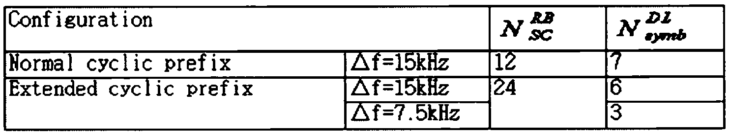
LTE 시스템에서 하나의 RB는 12개의 부반송파 x7(6)개의 OFDM(Orthogonal Frequency Division Multiplexing) 심볼 또는 SC-FDMA(Single Carrier-Frequency Division Multiple Access) 심볼을 포함한다. 데이터가 전송되는 단위 시간인 TTI(Transmission Time Interval)는 하나 이상의 서브프레임 단위로 정해질 수 있다. 상술한 무선 프레임의 구조는 예시에 불과하고, 무선 프레임에 포함되는 서브프레임의 수 또는 서브프레임에 포함되는 슬롯의 수, 슬롯에 포함되는 OFDM 심볼 또는 SC-FDMA 심볼의 수는 다양하게 변경될 수 있다.In an LTE system, one RB includes 12 subcarrier x 7 (6) Orthogonal Frequency Division Multiplexing (OFDM) symbols or Single Carrier-Frequency Division Multiple Access (SC-FDMA) symbols. A TTI (Transmission Time Interval), which is a unit time at which data is transmitted, may be defined in units of one or more subframes. The structure of the radio frame is merely an example, and the number of subframes included in a radio frame or the number of slots included in a subframe, the number of OFDM symbols included in a slot, or the number of SC-FDMA symbols may be variously changed have.
도 11은 3GPP LTE 시스템에서 사용되는 하향 링크의 시간-주파수 자원 격자 구조(resource grid structure)를 나타낸 도면이다.11 is a diagram illustrating a time-frequency resource grid structure of a downlink used in a 3GPP LTE system.
각 슬롯에서 전송되는 하향링크 신호는 ![]()
![]()
![]()
![]()
![]()
![]()
![]()
![]()
![]()
![]()
![]()
![]()
![]()
![]()
![]()
![]()
![]()
![]()
![]()
![]()
![]()
![]()
![]()
![]()
![]()
![]()
![]()
![]()
각 안테나 포트에 대한 자원 격자 내의 각 요소는 자원 요소(RE: Resource Element)라고 불리며, 슬롯 내의 인덱스 쌍 (k,l)에 의해 유일하게 식별된다. 여기서, k는 주파수 영역에서의 인덱스이고, l는 시간 영역에서의 인덱스이며 k는 0,...,![]()
![]()
![]()
![]()
도 9에 도시된 자원 블록은 어떤 물리 채널과 자원 요소들 간의 매핑(mapping) 관계를 기술하기 위해 사용된다. RB는 물리 자원 블록(PRB: Physical Resource Block)과 가상 자원 블록(VRB: Virtual Resource Block)으로 나눌 수 있다. 상기 하나의 PRB는 시간 영역의 ![]()
![]()
![]()
![]()
![]()
![]()
![]()
![]()
![]()
![]()
![]()
![]()
![]()
![]()
![]()
![]()
PRB는 주파수 영역에서 0에서 ![]()

![]()
상기 VRB의 크기는 PRB의 크기와 같다. VRB는 로컬형 VRB(Localized VRB, LVRB)와 분산형 VRB(Distributed VRB, DVRB)로 나뉘어 정의될 수 있다. 각 타입의 VRB에 대해, 하나의 서브프레임 내의 두 개의 슬롯에 있는 한 쌍의 VRB는 단일 VRB 넘버 nVRB가 함께 할당된다.The size of the VRB is equal to the size of the PRB. The VRB can be defined by dividing into a localized VRB (Localized VRB) and a distributed VRB (Distributed VRB). For each type of VRB, a pair of VRBs in two slots in one subframe are assigned together with a single VRB number n VRB .
상기 VRB은 PRB과 동일한 크기를 가질 수 있다. 두 가지 타입의 VRB이 정의되는데, 첫째 타입은 로컬형 VRB(Localized VRB, LVRB)이고, 둘째 타입은 분산형 VRB(Distributed VRB, DVRB)이다. 각 타입의 VRB에 대해, 한 쌍(pair)의 VRB이 단일의 VRB 인덱스 (이하, VRB 넘버(number)로 지칭될 수도 있다)를 가지고 1개의 서브프레임의 2개의 슬롯에 걸쳐 할당된다. 다시 말하면, 하나의 서브프레임을 구성하는 2개의 슬롯 중 제 1 슬롯에 속하는 ![]()
![]()
![]()
![]()
![]()
![]()
![]()
![]()
도 12는 3GPP LTE 시스템에서 사용되는 하향 링크 및 상향 링크의 서브 프레임의 구조를 나타낸 도면이다.12 is a diagram illustrating a structure of downlink and uplink subframes used in the 3GPP LTE system.
도 12a를 참조하면, 하나의 하향 링크 서브프레임은 시간 영역에서 2개의 슬롯을 포함한다. 하향 링크 서브프레임 내의 첫 번째 슬롯의 앞선 최대 3 OFDM 심볼들이 제어채널들이 할당되는 제어영역(control region)이고, 나머지 OFDM 심볼들은 PDSCH가 할당되는 데이터 영역(data region)이 된다.Referring to FIG. 12A, one downlink subframe includes two slots in the time domain. The maximum 3 OFDM symbols preceding the first slot in the DL subframe are control regions to which control channels are assigned and the remaining OFDM symbols are data regions to which the PDSCH is allocated.
3GPP LTE 시스템 등에서 사용되는 하향 링크 제어채널들은 PCFICH(Physical Control Format Indicator Channel), PDCCH(Physical Downlink Control Channel), PHICH(Physical Hybrid-ARQ Indicator Channel) 등이 있다. 서브프레임의 첫 번째 OFDM 심볼에서 전송되는 PCFICH는 서브프레임 내에서 제어채널들의 전송에 사용되는 OFDM 심볼의 수(즉, 제어 영역의 크기)에 관한 정보를 나른다. PDCCH를 통해 전송되는 제어정보를 하향 링크 제어정보(Downlink Control Information, DCI)라고 한다. DCI는 상향 링크 자원 할당 정보, 하향 링크 자원 할당 정보 및 임의의 단말 그룹들에 대한 상향 링크 전송 파워 제어 명령 등을 가리킨다. PHICH는 상향 링크 HARQ(Hybrid Automatic Repeat Request)에 대한 ACK/NACK 신호를 나른다. 즉, 단말이 전송한 상향 링크 데이터에 대한 ACK/NACK 신호는 PHICH 상으로 전송된다.The downlink control channels used in the 3GPP LTE system include a Physical Control Format Indicator Channel (PCFICH), a Physical Downlink Control Channel (PDCCH), and a Physical Hybrid-ARQ Indicator Channel (PHICH). The PCFICH transmitted in the first OFDM symbol of the subframe carries information on the number of OFDM symbols (i.e., the size of the control region) used for transmission of the control channels in the subframe. The control information transmitted through the PDCCH is referred to as downlink control information (DCI). DCI indicates uplink resource allocation information, downlink resource allocation information, and uplink transmission power control commands for arbitrary terminal groups. The PHICH carries an ACK / NACK signal for an uplink HARQ (Hybrid Automatic Repeat Request). That is, the ACK / NACK signal for the uplink data transmitted by the UE is transmitted on the PHICH.
이하에서 하향 링크 물리 채널인 PDCCH에 대해서 간략히 살펴보기로 한다.Hereinafter, the PDCCH as the downlink physical channel will be briefly described.
기지국은 PDCCH를 통해 PDSCH의 자원 할당 및 전송 포맷(이를 DL grant라고도 한다), PUSCH의 자원 할당 정보(이를 UL grant라고도 한다), 임의의 단말, 그룹 내 개별 단말들에 대한 전송 파워 제어 명령의 집합 및 VoIP(Voice over Internet Protocol)의 활성화 등을 전송할 수 있다. 복수의 PDCCH가 제어 영역 내에서 전송될 수 있으며, 단말은 복수의 PDCCH를 모니터링할 수 있다. PDCCH는 하나 또는 몇몇 연속적인 CCE(Control Channel Elements)의 집합(aggregation)으로 구성된다.The base station transmits a set of transmission power control commands for the PDSCH resource allocation and transmission format (also referred to as DL grant), PUSCH resource allocation information (also referred to as UL grant), an arbitrary terminal, And activation of VoIP (Voice over Internet Protocol). A plurality of PDCCHs can be transmitted in the control domain, and the UE can monitor a plurality of PDCCHs. The PDCCH consists of one or several consecutive aggregations of Control Channel Elements (CCEs).
하나 또는 몇몇 연속적인 CCE의 집합으로 구성된 PDCCH는 서브블록 인터리빙(subblock interleaving)을 거친 후에 제어 영역을 통해 전송될 수 있다. CCE는 무선채널의 상태에 따른 부호화율을 PDCCH에게 제공하기 위해 사용되는 논리적 할당 단위이다. CCE는 복수의 자원 요소 그룹(resource element group)에 대응된다. CCE의 수와 CCE들에 의해 제공되는 부호화율의 연관 관계에 따라 PDCCH의 포맷 및 가능한 PDCCH의 비트 수가 결정된다.A PDCCH composed of a set of one or several consecutive CCEs can be transmitted through the control domain after subblock interleaving. The CCE is a logical allocation unit used to provide the PDCCH with the coding rate according to the state of the radio channel. The CCE corresponds to a plurality of resource element groups. The format of the PDCCH and the number of bits of the possible PDCCH are determined according to the relationship between the number of CCEs and the coding rate provided by the CCEs.
PDCCH를 통해 전송되는 제어정보를 하향 링크 제어정보(downlink control information, DCI)라고 한다. 다음 표 2는 DCI 포맷에 따른 DCI를 나타낸다.The control information transmitted through the PDCCH is referred to as downlink control information (DCI). Table 2 below shows the DCI according to the DCI format.

DCI 포맷 0은 상향 링크 자원 할당 정보를 가리키고, DCI 포맷 1∼2는 하향 링크 자원 할당 정보를 가리키고, DCI 포맷 3, 3A는 임의의 단말 그룹들에 대한 상향 링크 TPC(transmit power control) 명령을 가리킨다.
LTE 시스템에서 기지국이 PDCCH를 전송을 위해 자원을 매핑하는 방안에 대해 간단히 살펴본다.In the LTE system, a brief description will be given of how a base station maps resources for transmission of a PDCCH.
일반적으로, 기지국은 PDCCH를 통하여 스케쥴링 할당 정보 및 다른 제어 정보를 전송할 수 있다. 물리 제어 채널은 하나의 집합(aggregation) 또는 복수 개의 CCE로 전송될 수 있다. 하나의 CCE는 9개의 자원 요소 그룹(Resource Element Group, REG)들을 포함한다. PCFICH(Physical Control Format Indicator Channel) 또는 PHICH(Physical Hybrid Automatic Repeat Request Indicator Channel)에 할당되지 않은 RBG의 개수는 NREG이다. 시스템에서 이용 가능한 CCE는 0부터 NCCE-1까지 이다(여기서, ![]()
![]()

표 3을 참조하면, 기지국은 제어 정보 등을 몇 개의 영역으로 보낼지에 따라 PDCCH 포맷을 결정할 수 있다. 단말은 CCE 단위로 제어 정보 등을 읽어서 오버헤드를 줄일 수 있다. 마찬가지로, 중계기도 R-CCE 단위로 제어 정보 등을 읽을 수 있다. LTE-A 시스템에서는, 임의의 중계기를 위한 R-PDCCH를 전송하기 위해 R-CCE(Relay-Control Channel Element) 단위로 자원 요소(Resource Element, RE)를 매핑할 수 있다.Referring to Table 3, the base station can determine the PDCCH format according to how many areas the control information and the like are transmitted. The UE can reduce the overhead by reading the control information in the CCE unit. Likewise, the repeater can also read the control information in R-CCE units. In the LTE-A system, a Resource Element (RE) can be mapped in units of R-CCE (Relay-Control Channel Element) to transmit R-PDCCH for an arbitrary repeater.
도 12b를 참조하면, 상향 링크 서브프레임은 주파수 영역에서 제어 영역 및 데이터 영역으로 나누어질 수 있다. 제어 영역은 상향 링크 제어 정보를 나르는 PUCCH로 할당된다. 데이터 영역은 사용자 데이터를 나르기 위한 PUSCH(Physical Uplink Shared CHannel)로 할당된다. 단일 반송파 특성을 유지하기 위하여, 하나의 단말은 PUCCH 및 PUSCH를 동시에 전송하지 않는다. 하나의 단말을 위한 PUCCH는 하나의 서브프레임에서 RB 페어로 할당된다. RB 페어에 속하는 RB들은 각 2개의 슬롯에서 서로 다른 부반송파를 차지하고 있다. PUCCH에 할당된 RB 페어는 슬롯 경계(slot boundary)에서 주파수 호핑된다.Referring to FIG. 12B, the uplink subframe may be divided into a control region and a data region in the frequency domain. The control region is allocated to a PUCCH carrying uplink control information. The data area is allocated to a PUSCH (Physical Uplink Shared CHannel) for carrying user data. To maintain single carrier characteristics, one terminal does not transmit PUCCH and PUSCH at the same time. The PUCCH for one UE is allocated to an RB pair in one subframe. RBs belonging to the RB pair occupy different subcarriers in each of the two slots. The RB pair assigned to the PUCCH is frequency hopped at the slot boundary.
도 13은 단일 반송파 상황에서 통신을 수행하는 예를 나타낸다. 도 10은 LTE 시스템에서의 통신 예에 대응할 수 있다.13 shows an example of performing communication in a single carrier situation. Fig. 10 can correspond to an example of communication in the LTE system.
도 13을 참조하면, 일반적인 FDD 방식 무선 통신 시스템은 하나의 하향링크 대역과 이에 대응하는 하나의 상향링크 대역을 통해 데이터 송수신을 수행한다. BS와 UE는 서브프레임 단위로 스케줄링된 데이터 및/또는 제어 정보를 송수신한다. 데이터는 상/하향링크 서브프레임에 설정된 데이터 영역을 통해 송수신되고, 제어 정보는 상/하향링크 서브프레임에 설정된 제어 영역을 통해 송수신 된다. 이를 위해, 상/하향링크 서브프레임은 다양한 물리 채널을 통해 신호를 나른다. 도 9는 편의상 FDD 방식을 위주로 설명했지만, 상술한 내용은 무선 프레임을 시간 영역에서 상/하향링크 구분함으로써 TDD 방식에도 적용될 수 있다.Referring to FIG. 13, a typical FDD wireless communication system performs data transmission / reception through one downlink band and one uplink band corresponding thereto. The BS and the UE transmit and receive the scheduled data and / or control information in units of subframes. Data is transmitted / received through the data area set in the uplink / downlink subframe, and control information is transmitted / received through the control area set in the uplink / downlink subframe. To this end, the uplink / downlink subframe carries signals over various physical channels. Although the FDD scheme has been described for the sake of convenience, the above description can also be applied to the TDD scheme by separating the radio frame from the uplink / downlink in the time domain.
도 14는 다중 반송파 상황 하에서 통신을 수행하는 예를 나타낸다.14 shows an example of performing communication under a multicarrier situation.
LTE-A 시스템은 보다 넓은 주파수 대역을 사용하기 위하여 복수의 상/하향링크 주파수 블록을 모다 더 큰 상/하향링크 대역폭을 사용하는 반송파 병합(carrier aggregation 또는 bandwidth aggregation) 기술을 사용한다. 다중 반송파 시스템 또는 반송파 병합(carrier aggregation, CA) 시스템은 광대역 지원을 위해 목표 대역(bandwidth)보다 작은 대역을 가지는 복수의 반송파를 집합하여 사용하는 시스템을 말한다. 목표 대역보다 작은 대역을 가지는 복수의 반송파를 집합할 때, 집합되는 반송파의 대역은 기존 시스템과의 호환(backward compatibility)을 위해 기존 시스템에서 사용하는 대역폭으로 제한될 수 있다. 예를 들어, 기존의 LTE 시스템은 1.4, 3, 5, 10, 15, 20MHz의 대역폭을 지원하며, LTE 시스템으로부터 개선된 LTE-A(LTE-Advanced) 시스템은 LTE에서 지원하는 대역폭들만을 이용하여 20MHz보다 큰 대역폭을 지원할 수 있다. 또는 기존 시스템에서 사용하는 대역폭과 상관없이 새로운 대역폭을 정의하여 반송파 병합을 지원할 수 있다. 다중 반송파는 반송파 병합 및 대역폭 집합과 혼용되어 사용될 수 있는 명칭이다. 또한, 반송파 병합은 인접한(contiguous) 반송파 병합과 인접하지 않은(non-contiguous) 반송파 병합을 모두 통칭한다.The LTE-A system uses a carrier aggregation or bandwidth aggregation technique that uses a larger uplink / downlink bandwidth than a plurality of uplink / downlink frequency blocks to use a wider frequency band. A multi-carrier system or a carrier aggregation (CA) system refers to a system in which a plurality of carriers having a bandwidth smaller than a target bandwidth are collected and used for broadband support. When a plurality of carriers having a band smaller than the target band are collected, the band of the collected carrier waves can be limited to the bandwidth used in the existing system for backward compatibility with the existing system. For example, existing LTE systems support bandwidths of 1.4, 3, 5, 10, 15, and 20 MHz, and improved LTE-A (LTE-Advanced) systems from LTE systems use only the bandwidths supported by LTE It can support bandwidths greater than 20MHz. Or it can support carrier merging by defining a new bandwidth regardless of the bandwidth used by the existing system. Multicarriers are names that can be used interchangeably with carrier merging and bandwidth aggregation. Carrier merging is also referred to as contiguous carrier merging and non-contiguous carrier merging.
예를 들어, 도 14를 참조하면, 상/하향링크에 각각 5개의 20MHz CC들이 모여서 100MHz 대역폭을 지원할 수 있다. 각각의 CC들은 주파수 영역에서 서로 인접하거나 비-인접할 수 있다. 도 14는 편의상 UL CC의 대역폭과 DL CC의 대역폭이 모두 동일하고 대칭인 경우를 도시하였다. 그러나 각 CC의 대역폭은 독립적으로 정해질 수 있다. 일 예로, UL CC의 대역폭은 5MHz(UL CC0) + 20MHz(UL CC1) + 20MHz(UL CC2) + 20MHz(UL CC3) + 5MHz(UL CC4)와 같이 구성될 수 있다. 또한, UL CC의 개수와 DL CC의 개수가 다른 비대칭적 반송파 병합도 가능하다. 비대칭적 반송파 병합은 가용한 주파수 대역의 제한으로 인해 발생하거나 네트워크 설정에 의해 인위적으로 조성될 수 있다. 일 예로, BS가 X개의 DL CC를 관리하더라도, 특정 UE가 수신할 수 있는 주파수 대역은 Y(≤X)개의 DL CC로 한정될 수 있다. 이 경우, UE는 상기 Y개의 CC를 통해 전송되는 DL 신호/데이터를 모니터하면 된다. 또한, BS가 L개의 UL CC를 관리하더라도, 특정 UE가 송신할 수 있는 주파수 대역은 M(≤L)개의 UL CC로 한정될 수 있다. 이와 같이 특정 UE에게 한정된 DL CC 혹은 UL CC를 특정 UE에서의 설정된 (configured) 서빙 (serving) UL 혹은 DL CC라고 부른다. BS는 상기 BS가 관리하는 CC들 중 일부 또는 전부를 활성화(activate)하거나, 일부 CC를 비활성화(deactivate)함으로써, 상기 UE에게 소정 개수의 CC를 할당할 수 있다. 상기 BS는 활성화/비활성화되는 CC를 변경할 수 있으며, 활성화/비활성화되는 CC의 개수를 변경할 수 있다. 한편, BS는 셀-특정적 혹은 UE-특정적으로 UE가 우선적으로 모니터/수신해야 하는 Z개의 DL CC(여기서, 1≤Z≤Y≤X)를 주요(main) DL CC로서 구성할 수 있다. 또한, BS는 셀-특정적 혹은 UE-특정적으로 UE가 우선적으로 송신하는 N개의 UL CC(여기서, 1≤N≤M≤L)를 주요(main) UL CC로서 구성할 수 있다. 이와 같이 특정 UE에게 한정된 주요 DL 혹은 UL CC를 특정 UE에서의 설정된 (configured) 서빙 (serving) UL 혹은 DL CC라고도 부른다. 반송파 병합에 대한 다양한 파라미터는 셀-특정적(cell-specific), UE 그룹-특정적(UE group-specific) 또는 UE-특정적(UE-specific)으로 설정될 수 있다.For example, referring to FIG. 14, five 20 MHz CCs can be aggregated on the uplink / downlink to support a 100 MHz bandwidth. Each CC may be adjacent or non-adjacent to one another in the frequency domain. FIG. 14 shows a case where the bandwidth of the UL CC and the bandwidth of the DL CC are both the same and symmetric. However, the bandwidth of each CC can be set independently. For example, the bandwidth of the UL CC may be configured as 5 MHz (UL CC0) + 20 MHz (UL CC1) + 20 MHz (UL CC2) + 20 MHz (UL CC3) + 5 MHz (UL CC4). Asymmetric carrier merging with different number of UL CCs and DL CCs is also possible. Asymmetric Carrier Merging may occur due to restrictions on available frequency bands or may be artificially created by network settings. For example, even if the BS manages X DL CCs, the frequency band that a specific UE can receive is limited to Y (? X) DL CCs. In this case, the UE monitors DL signals / data transmitted through the Y CCs. Also, even if the BS manages L UL CCs, the frequency band that a specific UE can transmit may be limited to M (L) UL CCs. The DL CC or UL CC defined for a particular UE is thus called a serving UL or DL CC in a particular UE. The BS can allocate a predetermined number of CCs to the UE by activating some or all CCs managed by the BS or deactivating some CCs. The BS may change the CC to be activated / deactivated, and may change the number of CCs to be activated / deactivated. On the other hand, the BS may configure Z DL CCs (where 1? Z? Y? X) that the UE should preferentially monitor / receive in a cell-specific or UE-specific manner as the main DL CC . In addition, the BS may configure N UL CCs (1? N? M? L) that are preferentially transmitted by the UE in a cell-specific or UE-specific manner as a main UL CC. The primary DL or UL CC defined for a particular UE is also referred to as a serving UL or DL CC in a particular UE. The various parameters for carrier merging may be set to cell-specific, UE group-specific or UE-specific.
일단 BS가 UE에 이용 가능한 CC를 셀-특정적 혹은 UE-특정적으로 할당하면, 상기 UE에 대한 CC 할당이 전면적으로 재구성되거나 상기 UE가 핸드오버되지 않는 한, 일단 할당된 CC 중 적어도 하나는 비활성화되지 않는다. 이하에서는, UE에 대한 CC 할당의 전면적인 재구성이 아닌 한 비활성화되지 않는 CC를 PCC(Primary CC)라고 칭하고, BS가 자유롭게 활성화/비활성화할 수 있는 CC를 SCC(Secondary CC)라고 칭한다. 단일 반송파 통신은 1개의 PCC를 UE와 BS 사이의 통신에 이용하며, SCC는 통신에 이용하지 않는다. 한편, PCC와 SCC는 제어정보를 기준으로 구분될 수도 있다. 예를 들어, 특정 제어정보는 특정 CC를 통해서만 송수신 되도록 설정될 수 있는데, 이러한 특정 CC를 PCC로 지칭하고, 나머지 CC(들)을 SCC(s)로 지칭할 수 있다. 예를 들어, PUCCH를 통해 전송되는 제어정보가 이러한 특정 제어정보에 해당할 수 있다. 이와 같이, PUCCH 상에서 전송되는 제어정보가 PCC를 통해서만 UE로부터 BS로 전송될 수 있는 경우, 상기 UE의 PUCCH가 존재하는 UL CC는 UL PCC로 지칭되고, 나머지 UL CC(들)은 UL SCC(s)로 지칭될 수 있다. 다른 예로, UE-특정적 CC가사용될 경우, 특정 UE는 DL 동기 시그널(synchronization signal, SS)을 특정 제어정보로서 BS로부터 수신할 수 있다. 이 경우, 상기 특정 UE가 상기 DL SS를 수신하여, 초기 DL 시간 동기를 맞춘 DL CC (다시 말해, 상기 BS의 네트워크에 접속을 시도하는데 이용한 DL CC)가 DL PCC(s)로 지칭되고, 나머지 DL CC(들)이 DL SCC(s)로 지칭될 수 있다. LTE-A release-10에 따른 통신 시스템의 경우, 다중 반송파 통신은 각 UE 당 1개의 PCC와 0개 또는 1개 이상의 부 SCC(s)가 통신에 이용된다. 그러나 이는 LTE-A 표준에 따른 정의이며, 추후 UE 당 다수의 PCC들을 통신에 이용하는 것이 허용될 수도 있다. PCC는 주 CC(primary CC), 앵커 CC(anchor CC) 혹은 주 반송파(primary carrier)라고 불릴 수 있으며, SCC는 부 셀(secondary CC) 혹은 부 반송파(secondary CC)라고 불릴 수도 있다.Once the BS has allocated cell-specific or UE-specific CCs available to the UE, at least one of the assigned CCs, once the CC allocation for the UE has been totally reconfigured or the UE is not handed over, It is not deactivated. Hereinafter, a CC that is not deactivated is referred to as PCC (Primary CC), and a CC that can be freely activated / deactivated by the BS is referred to as an SCC (Secondary CC), unless it is a full reconfiguration of the CC allocation for the UE. Single carrier communication uses one PCC for communication between UE and BS, and SCC does not use for communication. On the other hand, PCC and SCC may be classified based on control information. For example, specific control information may be set to be transmitted and received only via a specific CC, which may be referred to as PCC and the remaining CC (s) as SCC (s). For example, the control information transmitted via the PUCCH may correspond to this specific control information. Thus, when control information transmitted on the PUCCH can be transmitted only from the UE to the BS through the PCC, the UL CC in which the PUCCH of the UE exists is referred to as UL PCC, and the remaining UL CCs are UL SCC (s) ). ≪ / RTI > In another example, when a UE-specific CC is used, a particular UE may receive a DL synchronization signal (SS) as specific control information from the BS. In this case, the specific UE receives the DL SS and the DL CC (i.e., DL CC used for attempting to connect to the BS's network) corresponding to the initial DL time synchronization is referred to as DL PCC (s) The DL CC (s) may be referred to as DL SCC (s). In the case of a communication system according to LTE-A release-10, multi-carrier communication uses one PCC and zero or one sub SCC (s) per UE for communication. However, this is a definition according to the LTE-A standard, and it may be allowed to later use multiple PCCs per UE for communication. The PCC may be referred to as a primary CC, an anchor CC, or primary carrier, and the SCC may be referred to as a secondary CC or a secondary CC.
LTE-A는 무선 자원을 관리하기 위해 셀(cell)의 개념을 사용한다. 셀은 하향링크 자원(DL resources)과 상향링크 자원(UL resources)의 조합, 즉, DL CC와 UL CC의 조합으로 정의되며, 상향링크 자원은 필수 요소는 아니다. 그러나 이는 현재 LTE-A 표준에서의 정의이며, 추후 셀이 상향링크 자원 단독으로도 구성되는 것이 허용될 수도 있다. 따라서, 셀은 하향링크 자원 단독, 또는 하향링크 자원과 상향링크 자원으로 구성될 수 있다. 반송파 병합이 지원되는 경우, 하향링크 자원(또는, DL CC)의 반송파 주파수(carrier frequency)와 상향링크 자원(또는, UL CC)의 반송파 주파수 사이의 링키지(linkage)는 시스템 정보에 의해 지시될 수 있다. 예를 들어, 시스템 정보 블록 타입 2(System Information Block type 2, SIB2) 링키지에 의해서, DL 자원과 UL 자원의 조합이 지시될 수 있다. 여기서, 반송파 주파수라 함은 각 셀 혹은 CC의 중심 주파수(center frequency)를 의미한다. 주 주파수(Primary frequency)(또는 PCC) 상에서 동작하는 셀을 주 셀(Primary Cell, PCell)로 지칭하고, 부 주파수(Secondary frequency)(또는 SCC) 상에서 동작하는 셀(들)을 부 셀(Secondary Cell, SCell)(들)로 지칭할 수 있다. 주 주파수(혹은 PCC)라 함은 UE가 초기 연결 설정(initial connection establishment) 과정을 수행하거나 연결 재-설정(connection re-establishment) 과정을 시작하는 데 사용되는 주파수(또는 CC)를 의미한다. PCell은 핸드오버 과정에서 지시된 셀을 지칭할 수도 있다. 부 주파수(또는 SCC)라 함은 RRC 연결이 설정이 이루어진 이후에 구성 가능하고 추가적인 무선 자원을 제공하는데 사용될 수 있는 주파수(혹은 CC)를 의미한다. PCell과 SCell은 서빙 셀(serving cell)로 통칭할 수 있다. 따라서, RRC_CONNECTED 상태에 있지만 반송파 병합이 설정되지 않았거나 반송파 병합을 지원하지 않는 UE의 경우, PCell로만 구성된 서빙 셀이 단 하나 존재한다. 반면, RRC_CONNECTED 상태에 있고 반송파 병합이 설정된 UE의 경우, 하나 이상의 서빙 셀이 존재할 수 있고, 전체 서빙 셀에는 하나의 PCell과 하나 이상의 SCell이 포함될 수 있다. 다만, 추후 서빙 셀이 다수의 PCell들을 포함하는 것이 허용될 수도 있다. 반송파 병합을 위해, 네트워크는 초기 보안 활성화(initial security activation) 과정이 개시된 이후, 연결 설정 과정에서 초기에 구성되는 PCell에 부가하여 하나 이상의 SCell을 반송파 병합을 지원하는 UE를 위해 구성할 수 있다. 그러나 UE가 반송파 병합을 지원하더라도, 네트워크는 SCell을 부가하지 않고, PCell만을 상기 UE를 위해 구성할 수도 있다. PCell은 주 Cell(primary Cell), 앵커 Cell(anchor Cell) 혹은 주 반송파(primary carrier)라고 불릴 수도 있으며, SCell은 부 셀(secondary Cell) 혹은 부 반송파(secondary carrier)라고 불릴 수도 있다.LTE-A uses the concept of a cell to manage radio resources. A cell is defined as a combination of DL resources and UL resources, that is, a combination of DL CC and UL CC, and an uplink resource is not essential. However, this is a definition in the current LTE-A standard, and the cell may be allowed to be configured later in the UL resource alone as well. Therefore, the cell can be composed of downlink resources alone or downlink resources and uplink resources. If carrier merging is supported, the linkage between the carrier frequency of the downlink resource (or DL CC) and the carrier frequency of the UL resource (or UL CC) may be indicated by system information have. For example, a combination of a DL resource and a UL resource may be indicated by a system information block type 2 (SIB2) linkage. Here, the carrier frequency means a center frequency of each cell or CC. A cell operating on a primary frequency (or PCC) is referred to as a primary cell (PCell) and a cell operating on a secondary frequency (or SCC) is referred to as a secondary cell , SCell (s)). The primary frequency (or PCC) refers to the frequency (or CC) used by the UE to perform an initial connection establishment process or to initiate a connection re-establishment process. The PCell may refer to the cell indicated in the handover process. Sub frequency (or SCC) is the frequency (or CC) that can be used to provide additional radio resources that can be configured after the RRC connection is established. PCell and SCell can be collectively referred to as serving cells. Thus, for UEs that are in the RRC_CONNECTED state but no carrier merging is set, or that do not support carrier merging, there is only one serving cell consisting of only PCell. On the other hand, in the case of the UE in the RRC_CONNECTED state and the carrier merging is set, there may be one or more serving cells, and one serving cell and one or more serving cells may be included in the entire serving cell. However, the serving cell may be allowed to include a plurality of PCells at a later time. For carrier merging, the network may configure one or more SCells for UEs that support Carrier Merging, in addition to the PCell initially configured during the connection establishment process, after the initial security activation process is initiated. However, even if the UE supports carrier merging, the network may not configure SCell and configure only the PCell for the UE. PCell may be referred to as a primary cell, an anchor cell, or primary carrier, and SCell may be referred to as a secondary cell or a secondary carrier.
다중 반송파 시스템에서, BS는 복수의 데이터 유닛을 주어진 셀 (혹은 CC)(들) 상에서 UE에 전송할 수 있으며, 상기 UE는 일 서브프레임에서 상기 복수의 데이터 유닛에 대한 ACK/NACK들을 전송할 수 있다. UE는 하향링크 데이터 수신을 위한 PDSCH를 수신하는 하나 또는 복수의 셀 (혹은 DL CC)를 할당받을 수 있다. 상기 UE를 위한 셀 (혹은 DL CC)(들)은 RRC 시그널링에 의해 반-정적(semi-static)으로 구성(configure) 혹은 재구성될 수 있다. 또한, 상기 UE를 위한 셀 (혹은 DL CC)(들)은 L1/L2(MAC) 제어 시그널링에 의해 동적으로 활성화/비활성화될 수 있다. 그러므로 UE가 전송할 ACK/NACK 비트의 최대 개수는 상기 UE가 이용가능한 셀 (혹은 DL CC)에 따라 변하게 된다. 즉, UE가 전송할 ACK/NACK 비트의 최대 개수는 RRC에 의해 구성/재구성되거나 L1/L2 시그널링에 의해 활성화된 DL CC(혹은 구성된 서빙 셀(들))에 따라 변하게 된다.In a multi-carrier system, a BS may transmit a plurality of data units to a UE on a given cell (or CC) (s), and the UE may transmit ACK / NACKs for the plurality of data units in one subframe. The UE may be allocated one or a plurality of cells (or DL CCs) for receiving the PDSCH for downlink data reception. The cell (or DL CC) (s) for the UE may be configured or reconfigured semi-static by RRC signaling. In addition, the cell (or DL CC) (s) for the UE may be dynamically activated / deactivated by L1 / L2 (MAC) control signaling. Therefore, the maximum number of ACK / NACK bits to be transmitted by the UE changes according to the cell (or DL CC) available to the UE. That is, the maximum number of ACK / NACK bits to be transmitted by the UE changes depending on the DL CC (or the configured serving cell (s)) configured / reconfigured by RRC or activated by L1 / L2 signaling.
도 15는 본 명세서에 개시된 실시 예에 따른 LTE 시스템의 구조를 나타낸 블록도이다.15 is a block diagram illustrating the structure of an LTE system according to an embodiment disclosed herein.
도 15를 참조하면, 상기 LTE 시스템은 LTE 단말(300)과 LTE 기지국(400)을 포함한다.Referring to FIG. 15, the LTE system includes an
하양 링크에서 송신기는 상기 LTE 기지국(400)일 수 있으며, 수신기는 상기 LTE 단말(300)일 수 있다. 상향 링크에서는 송신기는 상기 LTE 단말(300)일 수 있으며, 수신기는 상기 LTE 기지국(400)일 수 있다.In the downlink, the transmitter may be the
상기 LTE 단말(300)은 프로세서(310), 메모리(320) 및 무선통신부(330)를 포함할 수 있다.The
상기 프로세서(310)는 제안된 절차 및/또는 본 명세서에 개시된 방법을 구현하도록 구성할 수 있다.The
상기 메모리(320)는 상기 프로세서(310)와 결합하고, 상기 프로세서(310)가 동작하기 위한 다양한 정보를 저장한다.The
상기 무선통신부(330)는 상기 프로세스(310)와 결합하고, 무선 신호를 전송 및/또는 수신한다.The
상기 LTE 기지국(400)은 프로세서(410), 메모리(420) 및 무선통신부(430)를 포함할 수 있다.The
상기 프로세서(410)는 제안된 절차 및/또는 본 명세서에 개시된 방법을 구현하도록 구성할 수 있다.The
상기 메모리(420)는 상기 프로세서(410)와 결합하고, 상기 프로세서(420)의 동작을 위한 다양한 정보를 저장한다.The
상기 무선통신부(430)는 상기 프로세서(410)와 결합하고, 무선 신호를 송신 및/또는 수신한다.The
상기 LTE 단말(300) 및/또는 상기 LTE 기지국(400)은 단일 안테나 및/또는 다중 안테나를 포함할 수 있다. 상기 LTE 단말(300) 및 상기 LTE 기지국(400) 중 적어도 하나가 다중 안테나를 갖는 경우, 상기 무선 통신 시스템은 다중 입력 다중 출력(MIMO) 시스템이라고 할 수 있다.The
하기에서, 본 명세서에 개시된 실시 예에 따른 WLAN 시스템과 LTE 시스템이 공존하는 이종 네트워크 환경에서 LTE 단말이 RTS 및 CTS 메시지를 통해 TVWS를 독점적으로 사용하여 데이터 통신을 수행하기 위한 구체적인 실시 예들을 도면을 참조하여 설명하도록 한다.Hereinafter, specific embodiments for performing data communication using the TVWS exclusively through the RTS and CTS messages in the heterogeneous network environment where the WLAN system and the LTE system coexist according to the embodiments disclosed herein are illustrated .
도 16은 본 명세서에 개시된 실시 예에 따른 이종 네트워크 환경에서의 무선 통신 시스템을 나타낸 블록도이다.16 is a block diagram illustrating a wireless communication system in a heterogeneous network environment according to an embodiment disclosed herein.
도 16을 참조하면, 이종 네트워크 환경에서의 무선 통신 시스템은 하나 이상의 WLAN 단말(101, 102), WLAN 기지국(200), 하나 이상의 LTE 단말(301, 302) 및 LTE 기지국(400)을 포함한다.Referring to FIG. 16, a wireless communication system in a heterogeneous network environment includes one or
상기 WLAN 단말(101, 102) 및 상기 LTE 단말(301, 302)은 고정되거나 이동성을 가질 수 있으며, UE(User Equipment), UT(User Terminal), SS(Subscriber Station), 무선기기(Wireless Device), AMS(Advanced Mobile Station) 등 다른 용어로 불릴 수 있다.The
상기 WLAN 단말(101, 102) 및 상기 LTE 단말(301, 302)은 이동 전자 기기(Mobile Terminal), 텔레매틱스 전자 기기(Telematics Terminal), 스마트 폰(Smart Phone), 휴대 전자 기기(Portable Terminal), 개인 정보 전자 기기(Personal Digital Assistant; PDA), 휴대용 멀티미디어 플레이어(Portable Multimedia Player; PMP), 노트북 컴퓨터, 태블릿 PC(Tablet PC), 와이브로(Wibro) 전자 기기, IPTV(Internet Protocol Television) 전자 기기, 텔레비전(Television), 3D 텔레비전, 영상 기기, 텔레매틱스(Telematics) 전자 기기, 내비게이션(Navigation) 전자 기기, AVN(Audio Video Navigation) 전자 기기 등과 같이 다양한 전자 기기일 수 있다.The
상기 WLAN 기지국(200)은 일반적으로 상기 WLAN 단말(101, 102)과 통신하는 고정된 지점(fixed station)을 말하며, 노드B(NodeB), BTS(Base Transceiver System), 액세스 포인트(Access Point) 등 다른 용어로 불릴 수 있다.The
상기 LTE 기지국(400)은 상기 LTE 단말(301, 302)의 통신을 제어하는 고정된 지점을 말한다.The
제 1 실시 예First Embodiment
제 1 실시 예는 상기 LTE 단말(300) 또는 상기 LTE 기지국(400) 중 데이터를 송신하고자 하는 주체가 상기 WLAN 단말(100)로 상기 RTS 및 CTS 메시지를 송신함으로써, 상기 임의의 채널을 독점적으로 사용하는 방법을 제공한다.The first embodiment is characterized in that the
도 17은 본 명세서에 개시된 실시 예에 따른 이종 네트워크 환경에서의 RTS 및 CTS 메시지를 이용한 네트워크 통신 방법을 나타낸 흐름도이다.17 is a flowchart illustrating a network communication method using RTS and CTS messages in a heterogeneous network environment according to an embodiment disclosed herein.
도 17을 참조하면, 상기 LTE 단말(300)은 상기 WLAN 단말(100)로 가상의 RTS 및 CTS 메시지를 송신한다(s210).Referring to FIG. 17, the
상기 LTE 단말(300)은 이종의 시스템을 사용하는 상기 WLAN 단말(100)로 임의의 채널을 사용하여, 상기 임의의 채널을 사용하기 위한 가상의 RTS 및 CTS 메시지를 송신할 수 있다. 이때, 상기 RTS 및 CTS 메시지는 상기 LET 단말(300)이 상기 LTE 기지국(400)으로 데이터를 송신하기 위한 것일 수 있다.The
상기 임의의 채널은 TVWS 밴드 내에서 임의의 주파수 대역에 해당하는 채널일 수 있다.The arbitrary channel may be a channel corresponding to an arbitrary frequency band within the TVWS band.
상기 RTS 및 CTS 메시지는 상기 WLAN 단말(100) 및 상기 WLAN 기지국(200)이 실질적으로 송신을 요구하거나 송신 가능함을 알리기 위한 것이 아니라, 상기 LTE 단말(300)이 상기 임의의 채널을 독점적으로 사용하기 위하여 WLAN 단말인 것처럼 가장 행위를 하는 것으로, 가상의 RTS 및 CTS 메시지이다.The RTS and CTS messages are used not to notify that the
상기 RTS 및 CTS 메시지는 상기 LTE 단말(300)이 상기 임의의 채널을 사용할 시간을 나타내는 NAV 값을 포함할 수 있다.The RTS and CTS messages may include a NAV value indicating a time when the
상기 LTE 단말(300)은 상기 WLAN 단말(100)이 아닌, 상기 WLAN 기지국(200)으로 상기 RTS 및 CTS 메시지를 송신할 수도 있다.The
또는, 상기 LTE 단말(300)은 상기 WLAN 기지국(200)으로 상기 RTS 메시지를 송신하고, 상기 WLAN 기지국(200)으로부터 상기 CTS 메시지를 수신할 수 있다. 상기 WLAN 기지국(200)은 상기에서 설명한 바와 같이 경쟁 기반 자원 할당을 위하여 상기 WLAN 기지국(200)의 서비스 영역 내에 존재하는 상기 WLAN 단말(100)로 상기 CTS 메시지를 송신할 수 있다.Alternatively, the
복수의 LTE 단말이 상기 WLAN 단말(100)로 상기 RTS 메시지 및 CTS 메시지를 송신하는 경우, 상기 LTE 기지국(400)에 의하여 상기 복수의 LTE 단말 간 우선 순위를 결정하거나, 상기 복수의 LTE 단말 중 임의의 LTE 단말에 대하여 데이터 송수신을 대기모드로 전환하는 알고리즘이 수행될 수 있다.When a plurality of LTE terminals transmit the RTS message and the CTS message to the
상기 LTE 기지국(400)이 상기 LTE 단말(300)로부터 송신된 상기 RTS 및 CTS 메시지를 수신하는 경우, 상기 LTE 기지국(400)은 이를 디코딩(decoding)하지 않을 수 있다. 즉, 상기 LTE 기지국(400)은 데이터 송수신에 있어서 간섭 신호가 될 수 있는 상기 RTS 및 CTS 메시지를 디코딩하지 않음으로써 제어할 수 있다. 이를 위해 상기 LTE 기지국(400)은 상기 RTS 및 CTS 메시지를 판별하기 위한 별도의 데이터 포맷 또는 판단 알고리즘을 수행할 수 있으며, 상기 LTE 단말(300)과 사전에 상기 판별을 위한 약정을 수행할 수 있다.When the
상기 RTS 및 CTS 메시지를 수신한 상기 WLAN 단말(100)은 상기 RTS 및 CTS 메시지에 포함된 상기 NAV 값을 참조하여, 상기 시간 동안 통신을 중단한다(s220).Upon receiving the RTS and CTS messages, the
상기 WLAN 단말(100)은 상기 임의의 채널에 대하여, 상기 임의의 채널을 사용하는 데이터 통신을 대기 모드로 설정하여 통신을 중단할 수 있다.The
그 다음, 상기 LTE 단말(300)은 상기 LTE 기지국(400)과 데이터 통신을 수행한다(s230).Then, the
상기 WLAN 단말(100)이 상기 임의의 채널을 사용한 데이터 통신을 중단하여 상기 임의의 채널에 대한 독점적 사용이 가능해지면, 상기 LTE 단말(300)은 상기 LTE 기지국(400)과 상기 NAV 값에 의해 설정된 상기 시간 동안 상기 임의의 채널을 사용하여 데이터 통신을 수행한다.When the
상기 데이터는 상기 LTE 단말(300)이 상기 LTE 기지국(400)으로 송신하고자 하는 업로드(upload) 데이터일 수 있다.The data may be upload data that the
상기 LTE 단말(300) 및 상기 LTE 기지국(400)이 데이터 송수신을 완료하면, 상기 WLAN 단말(100)은 상기 WLAN 기지국(200)과 상기 임의의 채널을 사용하여 데이터 통신을 수행한다(s240).When the
상기 WLAN 단말(100)은 상기 NAV 값에 의한 상기 시간이 지나면, 상기 임의의 채널을 사용하여 상기 WLAN 기지국(200)과 데이터 통신을 수행할 수 있다. 상기 WLAN 단말(100)은 상기 WLAN 기지국(200)과 RTS 및 CTS 메시지 교환을 통해 경쟁적으로 상기 임의의 채널을 점유하고 데이터 통신을 수행할 수 있다.The
본 명세서에 개시된 실시 예에 따르면, 상기 LTE 기지국(400)은 상기 WLAN 단말(100)로 가상의 RTS 및 CTS 메시지를 송신할 수 있다(s250).According to the embodiment disclosed herein, the
상기 LTE 기지국(400)은 이종의 시스템을 사용하는 상기 WLAN 단말(100)로 임의의 채널을 사용하여, 상기 임의의 채널을 사용하기 위한 가상의 RTS 및 CTS 메시지를 송신할 수 있다. 이때, 상기 RTS 및 CTS 메시지는 상기 LET 기지국(400)이 상기 LTE 단말(300)로 데이터를 송신하기 위한 것일 수 있다.The
상기 임의의 채널은 TVWS 밴드 내에서 임의의 주파수 대역에 해당하는 채널일 수 있다.The arbitrary channel may be a channel corresponding to an arbitrary frequency band within the TVWS band.
상기 RTS 및 CTS 메시지는 상기 LTE 기지국(400)이 상기 임의의 채널을 사용할 시간을 나타내는 NAV 값을 포함할 수 있다.The RTS and CTS messages may include a NAV value indicating a time when the
상기 LTE 기지국(400)은 상기 WLAN 단말(100)이 아닌, 상기 WLAN 기지국(200)으로 상기 RTS 및 CTS 메시지를 송신할 수도 있다. 상기 WLAN 기지국(200)은 상기에서 설명한 바와 같이 경쟁 기반 자원 할당을 위하여 상기 WLAN 기지국(200)의 서비스 영역 내에 존재하는 상기 WLAN 단말(100)로 상기 CTS 메시지를 송신할 수 있다.The
상기 LTE 단말(300)이 상기 LTE 기지국(400)으로부터 송신된 상기 RTS 및 CTS 메시지를 수신하는 경우, 상기 LTE 단말(300)은 이를 디코딩(decoding)하지 않을 수 있다. 즉, 상기 LTE 단말(300)은 데이터 송수신에 있어서 간섭 신호가 될 수 있는 상기 RTS 및 CTS 메시지를 디코딩하지 않음으로써 제어할 수 있다. 이를 위해 상기 LTE 단말(300)은 상기 RTS 및 CTS 메시지를 판별하기 위한 별도의 데이터 포맷 또는 판단 알고리즘을 수행할 수 있으며, 상기 LTE 기지국(400)과 사전에 상기 판별을 위한 약정을 수행할 수 있다.When the
상기 RTS 및 CTS 메시지를 수신한 상기 WLAN 단말(100)은 상기 RTS 및 CTS 메시지에 포함된 상기 NAV 값을 참조하여, 상기 시간 동안 통신을 중단한다(s260).The
상기 WLAN 단말(100)은 상기 임의의 채널에 대하여, 상기 임의의 채널을 사용하는 데이터 통신을 대기 모드로 설정하여 통신을 중단할 수 있다.The
그 다음, 상기 LTE 기지국(400)은 상기 LTE 단말(300)과 데이터 통신을 수행한다(s270).Then, the
상기 WLAN 단말(100)이 상기 임의의 채널을 사용한 데이터 통신을 중단하여 상기 임의의 채널에 대한 독점적 사용이 가능해지면, 상기 LTE 기지국(400)은 상기 LTE 단말(300)과 상기 NAV 값에 의해 설정된 상기 시간 동안 상기 임의의 채널을 사용하여 데이터 통신을 수행한다.When the
상기 데이터는 상기 LTE 기지국(400)이 상기 LTE 단말(300)로 송신하고자 하는 다운로드(download)데이터일 수 있다.The data may be download data that the
제 2 실시 예Second Embodiment
제 2 실시 예는 상기 LTE 기지국(400)이 상기 WLAN 단말(100)로 상기 RTS 및 CTS 메시지를 송신함으로써, 상기 임의의 채널을 독점적으로 사용하여 상기 LTE 단말(300)로부터 데이터를 수신하거나, 상기 LTE 단말(300)로 데이터를 송신하는 방법을 제공한다.The second embodiment is characterized in that the
도 18은 본 명세서에 개시된 다른 실시 예에 따른 이종 네트워크 환경에서의 RTS 및 CTS 메시지를 이용한 네트워크 통신 방법을 나타낸 흐름도이다.18 is a flowchart illustrating a network communication method using RTS and CTS messages in a heterogeneous network environment according to another embodiment disclosed herein.
도 18을 참조하면, 상기 LTE 기지국(400)은 상기 WLAN 단말(100)로 가상의 RTS 및 CTS 메시지를 송신한다(s310).Referring to FIG. 18, the
상기 LTE 기지국(400)은 이종의 시스템을 사용하는 상기 WLAN 단말(100)로 임의의 채널을 사용하여, 상기 임의의 채널을 사용하기 위한 가상의 RTS 및 CTS 메시지를 송신할 수 있다. 이때, 상기 RTS 및 CTS 메시지는 상기 LET 기지국(400)이 상기 LTE 단말(300)로부터 데이터를 수신하기 위한 것일 수 있다.The
상기 임의의 채널은 TVWS 밴드 내에서 임의의 주파수 대역에 해당하는 채널일 수 있다.The arbitrary channel may be a channel corresponding to an arbitrary frequency band within the TVWS band.
상기 RTS 및 CTS 메시지는 상기 LTE 기지국(400)이 상기 임의의 채널을 사용할 시간을 나타내는 NAV 값을 포함할 수 있다.The RTS and CTS messages may include a NAV value indicating a time when the
상기 LTE 기지국(400)은 상기 WLAN 단말(100)이 아닌, 상기 WLAN 기지국(200)으로 상기 RTS 및 CTS 메시지를 송신할 수도 있다.The
또는, 상기 LTE 기지국(400)은 상기 WLAN 기지국(200)으로 상기 RTS 메시지를 송신하고, 상기 WLAN 기지국(200)으로부터 상기 CTS 메시지를 수신할 수 있다. 상기 WLAN 기지국(200)은 상기에서 설명한 바와 같이 경쟁 기반 자원 할당을 위하여 상기 WLAN 기지국(200)의 서비스 영역 내에 존재하는 상기 WLAN 단말(100)로 상기 CTS 메시지를 송신할 수 있다.Alternatively, the
복수의 LTE 단말이 상기 WLAN 단말(100)로 상기 RTS 메시지 및 CTS 메시지를 송신하는 경우, 상기 LTE 기지국(400)에 의하여 상기 복수의 LTE 단말 간 우선 순위를 결정하거나, 상기 복수의 LTE 단말 중 임의의 LTE 단말에 대하여 데이터 송수신을 대기모드로 전환하는 알고리즘이 수행될 수 있다.When a plurality of LTE terminals transmit the RTS message and the CTS message to the
상기 RTS 및 CTS 메시지를 수신한 상기 WLAN 단말(100)은 상기 RTS 및 CTS 메시지에 포함된 상기 NAV 값을 참조하여, 상기 시간 동안 통신을 중단한다(s320).Upon receiving the RTS and CTS messages, the
상기 WLAN 단말(100)은 상기 임의의 채널에 대하여, 상기 임의의 채널을 사용하는 데이터 통신을 대기 모드로 설정하여 통신을 중단할 수 있다.The
그 다음, 상기 LTE 기지국(400)은 상기 LTE 단말(300)과 데이터 통신을 수행한다(s330).Then, the
상기 WLAN 단말(100)이 상기 임의의 채널을 사용한 데이터 통신을 중단하여 상기 임의의 채널에 대한 독점적 사용이 가능해지면, 상기 LTE 단말(300)은 상기 LTE 기지국(400)과 상기 NAV 값에 의해 설정된 상기 시간 동안 상기 임의의 채널을 사용하여 데이터 통신을 수행한다.When the
상기 데이터는 상기 LTE 기지국(400)이 상기 LTE 단말(300)로부터 수신하고자 하는 업로드(upload) 데이터일 수 있다.The data may be upload data that the
상기 LTE 기지국(400) 및 상기 LTE 단말(300)이 데이터 송수신을 완료하면, 상기 WLAN 단말(10)은 상기 WLAN 기지국(20)과 상기 임의의 채널을 사용하여 데이터 통신을 수행한다(s340).When the
상기 WLAN 단말(100)은 상기 NAV 값에 의한 상기 시간이 지나면, 상기 임의의 채널을 사용하여 상기 WLAN 기지국(200)과 데이터 통신을 수행할 수 있다. 상기 WLAN 단말(100)은 상기 WLAN 기지국(200)과 RTS 및 CTS 메시지 교환을 통해 경쟁적으로 상기 임의의 채널을 점유하고 데이터 통신을 수행할 수 있다.The
또한, 상기 LTE 기지국(400)은 상기 WLAN 단말(100)로 가상의 RTS 및 CTS 메시지를 송신할 수 있다(s350).In addition, the
상기 LTE 기지국(400)은 이종의 시스템을 사용하는 상기 WLAN 단말(100)로 임의의 채널을 사용하여, 상기 임의의 채널을 사용하기 위한 가상의 RTS 및 CTS 메시지를 송신할 수 있다. 이때, 상기 RTS 및 CTS 메시지는 상기 LET 기지국(400)이 상기 LTE 단말(300)로 데이터를 송신하기 위한 것일 수 있다.The
상기 RTS 및 CTS 메시지는 상기 LTE 기지국(400)이 상기 임의의 채널을 사용할 시간을 나타내는 NAV 값을 포함할 수 있다.The RTS and CTS messages may include a NAV value indicating a time when the
상기 RTS 및 CTS 메시지를 수신한 상기 WLAN 단말(100)은 상기 RTS 및 CTS 메시지에 포함된 상기 NAV 값을 참조하여, 상기 시간 동안 통신을 중단한다(s360).The
상기 WLAN 단말(100)은 상기 임의의 채널에 대하여, 상기 임의의 채널을 사용하는 데이터 통신을 대기 모드로 설정하여 통신을 중단할 수 있다.The
그 다음, 상기 LTE 기지국(400)은 상기 LTE 단말(300)과 데이터 통신을 수행한다(s370).Then, the
상기 WLAN 단말(100)이 상기 임의의 채널을 사용한 데이터 통신을 중단하여 상기 임의의 채널에 대한 독점적 사용이 가능해지면, 상기 LTE 기지국(400)은 상기 LTE 단말(300)과 상기 NAV 값에 의해 설정된 상기 시간 동안 상기 임의의 채널을 사용하여 데이터 통신을 수행한다.When the
상기 데이터는 상기 LTE 기지국(400)이 상기 LTE 단말(300)로 송신하고자 하는 다운로드(download)데이터일 수 있다.The data may be download data that the
상기의 실시 예들에서 이종 네트워크는 WLAN 시스템 및 LTE 시스템을 사용하는 단말 및 기지국으로 구성되어 있는 것으로 설명하였으나 이에 한정하지 않고, 본 명세서에 개시된 실시 예들은 서로 다른 시스템을 사용하는 단말 및 기지국을 포함하는 이종 네트워크에 적용될 수 있음에 유의하여야 한다.In the above embodiments, the heterogeneous network has been described as being composed of the WLAN system and the terminal and the base station using the LTE system, but the present invention is not limited thereto, and the embodiments disclosed herein may include terminals and base stations using different systems It should be noted that the present invention can be applied to heterogeneous networks.
본 발명이 속하는 기술 분야에서 통상의 지식을 가진 자라면 본 발명의 본질적인 특성에서 벗어나지 않는 범위에서 다양한 수정 및 변형이 가능할 것이다. 따라서, 본 발명에 개시된 실시 예들은 본 발명의 기술 사상을 한정하기 위한 것이 아니라 설명하기 위한 것이고, 이러한 실시 예에 의하여 본 발명의 기술 사상의 범위가 한정되는 것은 아니다. 본 발명의 보호 범위는 아래의 청구범위에 의하여 해석 되어야 하며, 그와 동등한 범위 내에 있는 모든 기술 사상은 본 발명의 권리범위에 포함되는 것으로 해석되어야 할 것이다.It will be understood by those skilled in the art that various changes in form and details may be made therein without departing from the spirit and scope of the invention as defined by the appended claims. Therefore, the embodiments disclosed in the present invention are intended to illustrate rather than limit the scope of the present invention, and the scope of the technical idea of the present invention is not limited by these embodiments. The scope of protection of the present invention should be construed according to the following claims, and all technical ideas within the scope of equivalents should be construed as falling within the scope of the present invention.
Claims (13)
송신국이 이종의 통신 기술을 이용하는 기지국 또는 이종의 단말로 상기 주파수 대역 내의 임의의 채널을 사용하기 위한 메시지를 송신하는 단계; 및
상기 송신국이 상기 임의의 채널을 사용하여 수신국과 데이터 통신을 수행하는 단계를 포함하되,
상기 메시지는, 상기 송신국이 상기 데이터 통신을 위해 상기 임의의 채널을 사용할 시간을 포함하고, 상기 메시지는, 상기 시간 동안 상기 메시지를 수신한 상기 이종의 기지국 또는 이종의 단말이 상기 임의의 채널을 사용하는 데이터 통신을 중단하게 하기 위한 메시지인 것을 특징으로 하는 통신 방법.A communication method in a heterogeneous network environment using the same frequency band,
Transmitting a message for a transmitting station to use a certain channel in the frequency band to a base station or heterogeneous terminal using heterogeneous communication technology; And
Wherein the transmitting station performs data communication with the receiving station using the arbitrary channel,
Wherein the message includes a time at which the transmitting station uses the arbitrary channel for data communication, and the message is a message indicating that the heterogeneous base station or heterogeneous terminal, which has received the message for the time, And a message for stopping the data communication to be used.
이동통신 기지국 또는 이동통신 단말인 것을 특징으로 하는 통신 방법.The transmitting station according to claim 1,
Wherein the mobile communication terminal is a mobile communication base station or a mobile communication terminal.
802.11 시스템을 사용하는 것을 특징으로 하는 통신 방법.The method of claim 1, wherein the heterogeneous base station and the heterogeneous terminal comprise:
802.11 system is used.
상기 802.11 시스템에 의해 구현되는 RTS(Request To Send) 및 CTS(Clear To Send) 메시지이고, 상기 시간은 NAV(Network Allocation Vector)인 것을 특징으로 하는 통신 방법.4. The method of claim 3,
A Request To Send (RTS) and a Clear To Send (CTS) message implemented by the 802.11 system, and the time is a Network Allocation Vector (NAV).
상기 송신국으로부터 상기 메시지를 수신한 경우, 상기 메시지를 디코딩하지 않는 것을 특징으로 하는 통신 방법.2. The method of claim 1,
And when the message is received from the transmitting station, the message is not decoded.
TV 방송용 유휴 주파수 대역(TVWS)에 포함되는 채널인 것을 특징으로 하는 통신 방법.2. The apparatus of claim 1,
And is included in an idle frequency band (TVWS) for TV broadcasting.
상기 이종의 기지국 또는 단말은 자원을 경쟁 기반으로 할당하는 방식인 것을 특징으로 하는 통신 방법.The method of claim 1, wherein the communication technology between the transmitting station and the receiving station allocates resources on a scheduling basis,
Wherein the different types of base stations or terminals allocate resources based on contention.
외부와 무선 신호를 송수신하기 위한 무선통신부; 및
상기 무선통신부를 제어하여 이종의 통신 기술을 이용하는 기지국 또는 이종의 단말로 상기 주파수 대역 내의 임의의 채널을 사용하기 위한 메시지를 송신하고, 상기 임의의 채널을 사용하여 이동통신 기지국과 데이터 통신을 수행하는 프로세서를 포함하되,
상기 메시지는, 상기 단말이 상기 데이터 통신을 위해 상기 임의의 채널을 사용할 시간을 포함하고, 상기 메시지는, 상기 시간 동안 상기 메시지를 수신한 상기 이종의 기지국 또는 이종의 단말이 상기 임의의 채널을 사용하는 데이터 통신을 중단하게 하기 위한 메시지인 것을 특징으로 하는 이동통신 단말.A mobile communication terminal in a heterogeneous network environment using the same frequency band,
A wireless communication unit for transmitting and receiving a wireless signal to and from the outside; And
A controller for controlling the wireless communication unit to transmit a message for using a certain channel in the frequency band to a base station using a different communication technology or a heterogeneous terminal and to perform data communication with the mobile communication base station using the arbitrary channel ≪ / RTI >
Wherein the message includes a time at which the terminal uses the arbitrary channel for data communication, and the message includes information indicating whether the heterogeneous base station or heterogeneous terminal, which has received the message during the time, Is a message for stopping data communication to be performed by the mobile communication terminal.
802.11 시스템을 사용하는 것을 특징으로 하는 이동통신 단말.9. The method of claim 8, wherein the heterogeneous base station and the heterogeneous terminal comprise:
Wherein the mobile communication terminal uses an 802.11 system.
상기 802.11 시스템에 의해 구현되는 RTS(Request To Send) 및 CTS(Clear To Send) 메시지이고, 상기 시간은 NAV(Network Allocation Vector)인 것을 특징으로 하는 이동통신 단말.10. The method of claim 9,
A Request To Send (RTS) and a Clear To Send (CTS) message implemented by the 802.11 system, and the time is a Network Allocation Vector (NAV).
상기 이동통신 기지국으로부터 상기 메시지를 수신한 경우, 상기 메시지를 디코딩하지 않는 것을 특징으로 하는 이동통신 단말.9. The apparatus of claim 8,
Wherein the mobile communication terminal does not decode the message when the message is received from the mobile communication base station.
TV 방송용 유휴 주파수 대역(TVWS)에 포함되는 채널인 것을 특징으로 하는 이동통신 단말.9. The apparatus of claim 8,
And is included in an idle frequency band (TVWS) for TV broadcast.
상기 이동통신 단말과 이동통신 기지국 간의 통신 기술은 자원을 스케줄링 기반으로 할당하는 방식이고,
상기 이종의 기지국 또는 단말은 자원을 경쟁 기반으로 할당하는 방식인 것을 특징으로 하는 이동통신 단말.9. The method of claim 8,
The communication technology between the mobile communication terminal and the mobile communication base station allocates resources on a scheduling basis,
Wherein the different types of base stations or terminals allocate resources based on contention.
Applications Claiming Priority (3)
| Application Number | Priority Date | Filing Date | Title |
|---|---|---|---|
| US201161492818P | 2011-06-03 | 2011-06-03 | |
| US61/492,818 | 2011-06-03 | ||
| PCT/KR2012/000901 WO2012165750A1 (en) | 2011-06-03 | 2012-02-08 | Network communication method and terminal in a heterogeneous network environment |
Publications (2)
| Publication Number | Publication Date |
|---|---|
| KR20140007947A KR20140007947A (en) | 2014-01-20 |
| KR101507867B1 true KR101507867B1 (en) | 2015-04-07 |
Family
ID=47259563
Family Applications (1)
| Application Number | Title | Priority Date | Filing Date |
|---|---|---|---|
| KR20137031838A KR101507867B1 (en) | 2011-06-03 | 2012-02-08 | Network communication method and terminal in a heterogeneous network environment |
Country Status (3)
| Country | Link |
|---|---|
| US (1) | US9363824B2 (en) |
| KR (1) | KR101507867B1 (en) |
| WO (1) | WO2012165750A1 (en) |
Families Citing this family (24)
| Publication number | Priority date | Publication date | Assignee | Title |
|---|---|---|---|---|
| US9565593B2 (en) | 2013-05-20 | 2017-02-07 | Qualcomm Incorporated | Techniques for selecting subframe type or for interleaving signals for wireless communications over unlicensed spectrum |
| MY181095A (en) * | 2013-09-13 | 2020-12-17 | Ericsson Telefon Ab L M | Systems and methods for a location server to efficiently obtain location information from a location management entity |
| US9554283B2 (en) | 2013-12-03 | 2017-01-24 | Apple Inc. | Carrier aggregation using unlicensed frequency bands |
| US9549080B2 (en) * | 2014-02-05 | 2017-01-17 | Apple Inc. | Wi-Fi signaling by cellular devices for coexistence in unlicensed frequency bands |
| KR102208668B1 (en) | 2014-06-30 | 2021-01-28 | 한국전자통신연구원 | Apparatus and Method for avoiding collisions between wireless communication system |
| WO2016006854A1 (en) * | 2014-07-07 | 2016-01-14 | 엘지전자 주식회사 | Terminal and method for receiving data through unlicensed band |
| US10506634B2 (en) * | 2014-07-09 | 2019-12-10 | Lg Electronics Inc. | Method and terminal for receiving data through unlicensed band in mobile communication system |
| US10356807B2 (en) | 2014-08-22 | 2019-07-16 | Qualcomm Incorporated | Techniques for transmitting and receiving channel occupancy identifiers over an unlicensed radio frequency spectrum band |
| US10560891B2 (en) * | 2014-09-09 | 2020-02-11 | Blackberry Limited | Medium Access Control in LTE-U |
| JP6619742B2 (en) * | 2014-09-26 | 2019-12-11 | 京セラ株式会社 | Base station and user terminal |
| WO2016048081A1 (en) * | 2014-09-26 | 2016-03-31 | 한국전자통신연구원 | Wireless channel access method and device |
| CN107113881B (en) | 2014-09-26 | 2021-01-15 | 韩国电子通信研究院 | Radio channel access method and apparatus |
| US9974053B2 (en) | 2014-10-09 | 2018-05-15 | Lg Electronics Inc. | Method and apparatus for allocating wireless resources according to resource allocation setting in WLAN |
| US20160128130A1 (en) * | 2014-10-31 | 2016-05-05 | Qualcomm Incorporated | Mixed-mode medium access control (mac) on a shared communication medium |
| PL3035764T3 (en) * | 2014-12-15 | 2019-02-28 | Alcatel Lucent | Reducing collision between cellular and non-cellular transmissions |
| US9730014B2 (en) * | 2014-12-22 | 2017-08-08 | Intel IP Corporation | Systems, methods, and devices for LTE, wi-fi, and bluetooth coexistence |
| EP3038411B1 (en) * | 2014-12-23 | 2023-10-11 | IPCom GmbH & Co. KG | Radio communication device and method for transmission resource allocation in a telecommunication network |
| KR102197510B1 (en) * | 2014-12-24 | 2021-01-04 | 삼성전자주식회사 | Apparatus and method for operating wireless local area network system |
| US10091114B2 (en) * | 2015-03-11 | 2018-10-02 | Nec Corporation | Asynchronous access and synchronous transmission for coexistence of wireless standards |
| US9876604B2 (en) * | 2015-05-06 | 2018-01-23 | Qualcomm, Incorporated | Channel bonding signaling to in-range devices |
| EP3113530B1 (en) * | 2015-06-30 | 2018-12-19 | Alcatel Lucent | A wireless communications node, and method of reserving a time period for communications on a spectrum band shared between two different wireless network technologies |
| US10452861B2 (en) | 2015-11-05 | 2019-10-22 | Samsung Electronics Co., Ltd. | Method, UE and network node for protecting user privacy in networks |
| WO2018143722A1 (en) | 2017-02-03 | 2018-08-09 | Samsung Electronics Co., Ltd. | Apparatus and method for transmitting/receiving of data in wireless communication system |
| US11044753B2 (en) | 2019-02-12 | 2021-06-22 | Qts Holdings, Llc | Method for collision avoidance in transfer of network packets |
Citations (1)
| Publication number | Priority date | Publication date | Assignee | Title |
|---|---|---|---|---|
| KR20070083321A (en) * | 2006-02-21 | 2007-08-24 | 주식회사 케이티 | Coexistence system to integrate heterogeneous wireless network devices using the same frequency band into one hardware board and its operation method |
Family Cites Families (10)
| Publication number | Priority date | Publication date | Assignee | Title |
|---|---|---|---|---|
| JP4666890B2 (en) * | 2003-04-28 | 2011-04-06 | ソニー株式会社 | COMMUNICATION SYSTEM, COMMUNICATION METHOD, AND COMMUNICATION DEVICE |
| US7715434B2 (en) * | 2003-07-30 | 2010-05-11 | Michael Andrew Fischer | Managing an access point in the presence of separate protocols that share the same communications channel |
| KR100728356B1 (en) | 2005-12-30 | 2007-06-13 | 한국과학기술원 | Apparatus and method for determining and avoiding co-channel interference in wireless personal area networks |
| US9258833B2 (en) * | 2006-02-09 | 2016-02-09 | Altair Semiconductor Ltd. | LTE/Wi-Fi coexistence |
| WO2008067505A2 (en) * | 2006-11-30 | 2008-06-05 | Conexant Systems, Inc. | Systems and methods for coexistence of wlan and bluetooth networks |
| US8886140B2 (en) * | 2008-10-14 | 2014-11-11 | Texas Instruments Incorporated | Systems and methods for silencing wireless devices |
| US8189526B2 (en) * | 2009-03-06 | 2012-05-29 | Samsung Electronics Co., Ltd. | Method and system for shared communication medium in wireless communication systems |
| KR101619819B1 (en) | 2009-04-15 | 2016-05-13 | 광운대학교 산학협력단 | Method and Apparatus for Coexistence of Heterogeneous Wireless Communication Systems in Shared Frequency Band |
| KR101859589B1 (en) * | 2010-08-16 | 2018-06-28 | 삼성전자 주식회사 | Method and appratus for avoiding inteference from in-device communication module in wireless communication system |
| US8660109B2 (en) * | 2011-05-20 | 2014-02-25 | Renesas Mobile Corporation | Apparatus and method for controlling communication |
-
2012
- 2012-02-08 US US14/123,498 patent/US9363824B2/en not_active Expired - Fee Related
- 2012-02-08 WO PCT/KR2012/000901 patent/WO2012165750A1/en active Application Filing
- 2012-02-08 KR KR20137031838A patent/KR101507867B1/en not_active IP Right Cessation
Patent Citations (1)
| Publication number | Priority date | Publication date | Assignee | Title |
|---|---|---|---|---|
| KR20070083321A (en) * | 2006-02-21 | 2007-08-24 | 주식회사 케이티 | Coexistence system to integrate heterogeneous wireless network devices using the same frequency band into one hardware board and its operation method |
Also Published As
| Publication number | Publication date |
|---|---|
| KR20140007947A (en) | 2014-01-20 |
| US20140126504A1 (en) | 2014-05-08 |
| WO2012165750A1 (en) | 2012-12-06 |
| US9363824B2 (en) | 2016-06-07 |
Similar Documents
| Publication | Publication Date | Title |
|---|---|---|
| KR101507867B1 (en) | Network communication method and terminal in a heterogeneous network environment | |
| US11968679B2 (en) | Methods, systems, and apparatuses for beam management | |
| TWI737783B (en) | Methods for flexible resource usage | |
| US20210144743A1 (en) | Wireless Communications For Scheduling Transmissions | |
| TWI658709B (en) | Methods and apparatus for indicating and implementing of new ue capability | |
| JP6878278B2 (en) | Terminals, wireless communication methods, base stations and systems | |
| US20200037362A1 (en) | Method, apparatus, and system for channel access in unlicensed band | |
| US10278141B2 (en) | Method for transmitting uplink signal and user equipment, and method for receiving uplink signal and base station | |
| US20190097762A1 (en) | HARQ Feedback For Grant-Free Transmission | |
| US10327258B2 (en) | Method and user equipment for receiving downlink control information, and method and base station for transmitting downlink control information | |
| CN104604175B (en) | The user equipment and method that condition hybrid automatic repeat-request HARQ for carrier aggregation CA maps | |
| CA3119114A1 (en) | Transmission using a plurality of wireless resources | |
| JP6938390B2 (en) | Terminals, wireless communication methods, base stations and systems | |
| CN111066371B (en) | Method and apparatus for transmitting downlink control information in wireless communication system | |
| US8811303B2 (en) | Method of performing wireless communication in multi-carrier system | |
| KR20230012664A (en) | 5g nr data delivery for flexible radio services | |
| CN110447298B (en) | Method, device and system for transmitting physical channel in unlicensed band | |
| KR20210125115A (en) | Method and apparatus for performing physical layer mobility procedures | |
| JP2020057824A (en) | Base station device, terminal device, and communication method | |
| CN112567866A (en) | Method, device and system for channel access in unlicensed frequency band | |
| EP3357184B1 (en) | Method, apparatus and computer program for transmitting physical layer signals | |
| CA3126568A1 (en) | Channel access for wireless communication | |
| JP2019517755A (en) | Paging detection window | |
| CN114208369A (en) | Channel access method for performing transmission in unlicensed band and apparatus using the same | |
| CN113170511B (en) | Method for transmitting and receiving physical channel and signal based on bandwidth part (BWP) of unlicensed band and apparatus using the same |
Legal Events
| Date | Code | Title | Description |
|---|---|---|---|
| A201 | Request for examination | ||
| E701 | Decision to grant or registration of patent right | ||
| GRNT | Written decision to grant | ||
| LAPS | Lapse due to unpaid annual fee |