KR101452995B1 - Aparatus and method for estimation i/q mismatch parameter in ofdm receiver - Google Patents
Aparatus and method for estimation i/q mismatch parameter in ofdm receiver Download PDFInfo
- Publication number
- KR101452995B1 KR101452995B1 KR1020080014749A KR20080014749A KR101452995B1 KR 101452995 B1 KR101452995 B1 KR 101452995B1 KR 1020080014749 A KR1020080014749 A KR 1020080014749A KR 20080014749 A KR20080014749 A KR 20080014749A KR 101452995 B1 KR101452995 B1 KR 101452995B1
- Authority
- KR
- South Korea
- Prior art keywords
- pilot tone
- phase difference
- amplitude difference
- difference
- estimating
- Prior art date
Links
Images


Classifications
-
- H—ELECTRICITY
- H04—ELECTRIC COMMUNICATION TECHNIQUE
- H04L—TRANSMISSION OF DIGITAL INFORMATION, e.g. TELEGRAPHIC COMMUNICATION
- H04L27/00—Modulated-carrier systems
- H04L27/26—Systems using multi-frequency codes
- H04L27/2601—Multicarrier modulation systems
- H04L27/2647—Arrangements specific to the receiver only
- H04L27/2655—Synchronisation arrangements
- H04L27/2668—Details of algorithms
- H04L27/2673—Details of algorithms characterised by synchronisation parameters
- H04L27/2675—Pilot or known symbols
-
- H—ELECTRICITY
- H04—ELECTRIC COMMUNICATION TECHNIQUE
- H04L—TRANSMISSION OF DIGITAL INFORMATION, e.g. TELEGRAPHIC COMMUNICATION
- H04L27/00—Modulated-carrier systems
- H04L27/26—Systems using multi-frequency codes
- H04L27/2601—Multicarrier modulation systems
- H04L27/2647—Arrangements specific to the receiver only
-
- H—ELECTRICITY
- H04—ELECTRIC COMMUNICATION TECHNIQUE
- H04L—TRANSMISSION OF DIGITAL INFORMATION, e.g. TELEGRAPHIC COMMUNICATION
- H04L27/00—Modulated-carrier systems
- H04L27/26—Systems using multi-frequency codes
- H04L27/2601—Multicarrier modulation systems
- H04L27/2602—Signal structure
- H04L27/261—Details of reference signals
- H04L27/2613—Structure of the reference signals
-
- H—ELECTRICITY
- H04—ELECTRIC COMMUNICATION TECHNIQUE
- H04L—TRANSMISSION OF DIGITAL INFORMATION, e.g. TELEGRAPHIC COMMUNICATION
- H04L27/00—Modulated-carrier systems
- H04L27/26—Systems using multi-frequency codes
- H04L27/2601—Multicarrier modulation systems
- H04L27/2647—Arrangements specific to the receiver only
- H04L27/2655—Synchronisation arrangements
- H04L27/2666—Acquisition of further OFDM parameters, e.g. bandwidth, subcarrier spacing, or guard interval length
-
- H—ELECTRICITY
- H04—ELECTRIC COMMUNICATION TECHNIQUE
- H04L—TRANSMISSION OF DIGITAL INFORMATION, e.g. TELEGRAPHIC COMMUNICATION
- H04L27/00—Modulated-carrier systems
- H04L27/26—Systems using multi-frequency codes
- H04L27/2601—Multicarrier modulation systems
- H04L27/2647—Arrangements specific to the receiver only
- H04L27/2655—Synchronisation arrangements
- H04L27/2689—Link with other circuits, i.e. special connections between synchronisation arrangements and other circuits for achieving synchronisation
- H04L27/2695—Link with other circuits, i.e. special connections between synchronisation arrangements and other circuits for achieving synchronisation with channel estimation, e.g. determination of delay spread, derivative or peak tracking
-
- H—ELECTRICITY
- H04—ELECTRIC COMMUNICATION TECHNIQUE
- H04L—TRANSMISSION OF DIGITAL INFORMATION, e.g. TELEGRAPHIC COMMUNICATION
- H04L27/00—Modulated-carrier systems
- H04L27/32—Carrier systems characterised by combinations of two or more of the types covered by groups H04L27/02, H04L27/10, H04L27/18 or H04L27/26
- H04L27/34—Amplitude- and phase-modulated carrier systems, e.g. quadrature-amplitude modulated carrier systems
- H04L27/38—Demodulator circuits; Receiver circuits
- H04L27/3845—Demodulator circuits; Receiver circuits using non - coherent demodulation, i.e. not using a phase synchronous carrier
- H04L27/3854—Demodulator circuits; Receiver circuits using non - coherent demodulation, i.e. not using a phase synchronous carrier using a non - coherent carrier, including systems with baseband correction for phase or frequency offset
- H04L27/3863—Compensation for quadrature error in the received signal
-
- H—ELECTRICITY
- H04—ELECTRIC COMMUNICATION TECHNIQUE
- H04L—TRANSMISSION OF DIGITAL INFORMATION, e.g. TELEGRAPHIC COMMUNICATION
- H04L5/00—Arrangements affording multiple use of the transmission path
- H04L5/003—Arrangements for allocating sub-channels of the transmission path
- H04L5/0048—Allocation of pilot signals, i.e. of signals known to the receiver
Abstract
본 발명은 직교 주파수 분할 다중 수신기에서 아이/큐 불균형 파라미터를 추정하는 장치 및 방법에 관한 것으로서, 수신되는 신호의 프리앰블(Preamble)에서 파일럿톤(Pilot Tone)의 위치를 기반으로 진폭차와 위상차를 추정하는 불균형 파라미터 추정기와, 상기 불균형 파라미터 추정기에 의해 추정된 진폭차와 위상차를 통해 I/Q 불균형을 보상하는 I/Q 보상회로를 포함함으로써 구현이 간단하고 I/Q 불균형의 실시간 교정이 가능하다.The present invention relates to an apparatus and method for estimating an eye / queue unbalance parameter in an orthogonal frequency division multiplexing receiver, and more particularly, to an apparatus and method for estimating an eye / And an I / Q compensation circuit for compensating an I / Q imbalance through an amplitude difference and a phase difference estimated by the imbalance parameter estimator, realizing simple implementation and real-time correction of an I / Q imbalance.
I/Q mismatch, 프리앰블(Preamble), OFDM, 진폭차, 위상차 I / Q mismatch, preamble, OFDM, amplitude difference, phase difference
Description
본 발명은 직교 주파수 분할 다중 수신기에서 아이/큐 불균형 파라미터를 추정하는 장치 및 방법에 관한 것으로, 특히, 상기 휴대용 단말기의 외장 메모리에 저장된 파일을 효율적으로 관리하기 위한 방법 및 장치에 관한 것이다.The present invention relates to an apparatus and method for estimating an eye / queue unbalance parameter in an orthogonal frequency division multiplexing receiver, and more particularly, to a method and apparatus for efficiently managing a file stored in an external memory of the portable terminal.
대부분의 무선 통신 단말기는 수신 신호를 여러 개의 믹서를 통과하여 여러단의 IF단을 거쳐 기저대역(Baseband)이나 낮은 중간주파수(IF)단으로 하향변환(down-conversion)하는 아날로그 헤테로다인(heterodyne) 수신방식을 채택하여 사용되어 왔으며 현재도 널리 사용되고 있다. Most wireless communication terminals include an analog heterodyne that downconverts a received signal through a plurality of mixers and through a plurality of IF stages to a baseband or a lower intermediate frequency (IF) Reception method has been used and has been widely used today.
그러나, 다수의 아날로그의 부품을 사용하는 기존의 수신구조는 그 회로가 복잡하여 하나의 칩으로 집적화(integration)하기 어려우며, 또한 수신기 부피가 커지게 되는 단점이 있다. 더욱이 전력소모도 많아지게 되어 PDA나 무선단말기 같 은 소형화 및 이동성을 중요시하는 개인 이동통신기기에 적합하지 않다. However, a conventional receiving structure using a plurality of analog components has a disadvantage that it is difficult to integrate into a single chip due to the complexity of the circuit, and the receiver volume becomes large. Furthermore, power consumption is increased, which is not suitable for a personal mobile communication device such as a PDA or a wireless terminal that emphasizes miniaturization and mobility.
상술한 문제점들을 해결하기 위하여 현재의 단말기에는 직접변환(direct-conversion)방식을 수신기의 기본 구조로 채택하고 있으며, 앞으로 이 구조는 더욱 널리 사용될 것이다. 이런 방식은 하나의 믹서를 사용하여 단 한번의 주파수 하향변환을 수행하게 되므로 RF부분을 최소화시킬 수 있는 장점이 있고 하드웨어 측면에서 헤테로다인 방식보다 좀 더 유연한(flexible) 특징을 지닌다. 그러므로 소프트웨어의 기능이 중요시되는 차세대 통신기술인 software-defined radio(SDR)개념에 더욱 근접하는 수신기 구조라고 할 수 있다. 상기 SDR시스템은 하드웨어 교체 없이 소프트웨어의 변경만으로 새로운 통신표준을 수용할 수 있는 시스템이므로 시스템 유연성(flexibility) 및 재구성이 가장 중요한 요소이기 때문이다. In order to solve the above-mentioned problems, a direct-conversion type is adopted as a basic structure of a receiver in a current terminal, and this structure will be used more widely in the future. This method has the advantage of minimizing the RF part since it performs a single frequency down conversion using a single mixer and has a more flexible characteristic than the heterodyne method in terms of hardware. Therefore, the receiver structure is closer to the software-defined radio (SDR) concept, which is the next generation communication technology where the function of software is important. Since the SDR system is a system that can accommodate a new communication standard only by changing software without hardware replacement, flexibility and reconfiguration are the most important factors.
따라서, 이러한 SDR을 구현하기 위해서 먼저 RF부분의 최소화, 즉 ADC(analog-to-digital converter)를 안테나에 최대한 가깝게 설계하여야 한다. 그러나 이상적인 SDR 시스템은 현재 기술로는 아직까지 불가능하기 때문에 하나의 믹서를 사용하는 직접변환 방식이 좀 더 현실적이라고 할 수 있다. Therefore, in order to realize such SDR, it is necessary to minimize the RF part, that is, to design an analog-to-digital converter (ADC) as close as possible to the antenna. However, since the ideal SDR system is not yet possible with current technology, direct conversion using a single mixer is more realistic.
하지만, 이러한 직접변환 방식은 국부 발진기의 주파수의 누설(leakage)에 의한 DC옵셋 문제와 1/f 잡음이라고도 불리는 플리커(flicker)잡음을 포함한 DC대역 부근에서 발생되는 잡음에 의해 큰 영향을 받는다. 또한 I채널과 Q채널 사이의 위상 및 진폭이 서로 어긋나 발생하는 I/Q 불균형 문제도 발생한다. 이 문제들 중에서 DC부근의 잡음들은 최근에 회로 및 칩 기술의 발달로 인해 상당한 진전이 이루어지고 있다. However, this direct conversion scheme is greatly influenced by the DC offset problem due to the frequency leakage of the local oscillator and the noise generated near the DC band including flicker noise, also referred to as 1 / f noise. In addition, there arises a problem of I / Q imbalance in which the phases and amplitudes of the I and Q channels are shifted from each other. Of these problems, noise around the DC has been making considerable progress recently due to the development of circuit and chip technology.
그러나, I/Q 불균형 문제는 믹서 통과 후 I채널과 Q채널의 서로 다른 증폭기 및 필터를 사용하므로 불균형이 전체 수신기 성능을 열화시키는 요소로서 여전히 작용하므로 이를 보상하는 회로 또는 신호처리가 반드시 요구된다.However, since the I / Q imbalance problem uses different amplifiers and filters of the I channel and the Q channel after passing through the mixer, the imbalance still acts as a factor deteriorating the overall receiver performance.
이러한 I/Q 불균형은 자기 신호의 스펙트럼이 반전되고 complex conjugate된 신호가 기저대역 수신신호에 간섭으로 작용하게 되어 악영향을 미치게 된다. 다시 말하면 RF부분의 쿼드러쳐 믹싱(quadrature mixing) 구조는 수신된 RF 신호를 믹서에 의하여 하향변환이 되어 직접 기저대역으로 이동시키지만, 이러한 쿼드러쳐 구조는 아날로그 회로이기 때문에 완전하게 이상적이지 못해 I/Q 불균형이 조금이나마 남아 있게 된다. 상기 불균형에 의해 음의 주파수 대역의 RF신호의 일부가 오히려 상향 변환(up-conversion)되어 기저대역으로 이동하게 된다. 즉, 이 신호가 우리가 원하는 하향변환된 신호와 간섭을 일으키게 되는 것이다. This I / Q imbalance has an adverse effect because the spectrum of the magnetic signal is inverted and the complex conjugated signal acts as an interference to the baseband received signal. In other words, the quadrature mixing structure of the RF section shifts the received RF signal down-converted by the mixer directly to the baseband. However, since this quadrature structure is an analog circuit, it is not completely ideal, There is a slight imbalance. Due to the unbalance, a part of the RF signal in the negative frequency band is up-converted and moved to the baseband. That is, this signal will interfere with the desired down-converted signal.
더욱이 이 불균형 정도가 커질수록 상향 변환된 신호의 성분이 더욱 크게 증가되어, 수신신호 복구가 불가능한 상태에 이르게 될 수도 있다. 또한, 이러한 I/Q 불균형은 수신신호의 성상점(constellation)도 크게 회전시켜, 결과적으로 비트에러율(BER)성능을 크게 떨어뜨린다.Furthermore, as the degree of the imbalance increases, the components of the up-converted signal may be further increased, leading to a state in which the received signal can not be recovered. In addition, such an I / Q imbalance greatly rotates the constellation of the received signal, resulting in a drastic decrease in bit error rate (BER) performance.
상기 I/Q 불균형을 보상하는 가장 일반적인 방법에는 단말을 제작한 후 최종 테스트 할 때 적절한 test tone을 발생시켜 I/Q 불균형을 직접 측정한 후 교정하여 공장에서 출하하는 방법을 사용한다. 이 방법은 I/Q 불균형에 의해 발생하는 이미지 tone을 검출하여 I/Q 불균형 보상기에 적용하는 방법이다. 또한 디지털 영역에서 I/Q 불균형을 보상하는 방법에는 LMS(least mean square)나 RLS(recursive least square)같은 적응신호처리 방식이나 SAD(symmetric adaptive decorrelation)기법 등의 DSP 신호처리방식을 사용하고 있다.The most common method for compensating for the I / Q imbalance is to measure the I / Q imbalance by generating a proper test tone when the final test is performed after manufacturing the terminal, and then calibrate the I / Q imbalance to use the factory shipped method. This method detects the image tone generated by the I / Q imbalance and applies it to the I / Q imbalance compensator. In order to compensate the I / Q imbalance in the digital domain, a DSP signal processing method such as an adaptive signal processing method such as LMS (least mean square) or recursive least square (RLS) or a symmetric adaptive decorrelation (SAD) technique is used.
최근에는 OFDM 시스템에서도 I/Q불균형을 제거하는 여러 방식들이 제안되고 있으나, 상기 OFDM 시스템에서도 위와 같은 적응신호 처리 방식을 채택하고 있거나, 다수의 OFDM 심볼로부터 I/Q 불균형값을 추정하여 보상하는 방법을 사용하고 있어 3GPP LTE나 Mobile WiMAX등의 표준에 적합하지 않으며 정현파인 테스트 톤(test tone)을 칩 내부에서 발생시켜 I/Q 불균형을 보상하는 방법은 실제 데이터 송수신시 테스트 톤을 발생하게 되면 데이터와 충돌이 발생하기 때문에 I/Q를 교정하는 것이 불가능하다. 그러므로, 이 방식은 온도 변화등 환경에 따른 영향에 적응적으로 대처하기가 매우 어렵다. 또한, 실시간으로 교정이 가능한 DSP 신호처리 방식은 반복 및 수렴 과정들을 포함하고 있으므로 여러 개의 훈련심볼과 많은 계산시간을 필요로 하는 단점이 있다. Recently, various schemes for eliminating I / Q imbalance have been proposed in the OFDM system. However, in the OFDM system, the adaptive signal processing method is adopted, or a method of estimating and compensating an I / Q imbalance value from a plurality of OFDM symbols , A method of compensating for I / Q imbalance by generating test tones within a chip that does not conform to standards such as 3GPP LTE or Mobile WiMAX and compensates for I / Q imbalance by generating sinusoidal test tones, It is impossible to correct the I / Q. Therefore, this method is very difficult to adaptively cope with environmental influences such as temperature change. In addition, since the DSP signal processing method capable of correcting in real time includes repetition and convergence processes, it requires a plurality of training symbols and a long calculation time.
또한, 상기 OFDM 방식에서도 I/Q 불균형을 제거하는 방식들이 제안되고 있으나 이러한 방식에서도 마찬가지로 상기와 같은 수렴과정이 필요하거나, I/Q 불균형 추정만을 위한 특정한 파일럿 구조가 요구된다. 또한, 정확한 추정을 위해 다수의 OFDM preamble로부터 I/Q 불균형값을 얻어서 보상하는 방법도 제안되고 있지만 이러한 프리앰블 구조나 방식들이 현재의 표준인 3GPP LTE나 Mobile WiMAX에 적용하기 힘든 점과 구현이 복잡한 문제가 있다.Also, in the OFDM scheme, schemes for eliminating the I / Q imbalance have been proposed. However, such a scheme requires a convergence process as described above or a specific pilot structure for only I / Q imbalance estimation. Also, a method of obtaining I / Q imbalance values from a plurality of OFDM preamble for accurate estimation is proposed, but it is difficult to apply such preamble structure or methods to 3GPP LTE or Mobile WiMAX, which is a current standard, .
본 발명의 목적은 직교 주파수 분할 다중 수신기에서 아이/큐 불균형 파라미터를 추정하는 장치 및 방법을 제공함에 있다. It is an object of the present invention to provide an apparatus and method for estimating an eye / queue imbalance parameter in an orthogonal frequency division multiplexing receiver.
본 발명의 다른 목적은 수신된 OFDM 프리앰블 값을 통해 I/Q 불균형을 보상하는 장치 및 방법을 제공함에 있다.It is another object of the present invention to provide an apparatus and a method for compensating an I / Q imbalance through a received OFDM preamble value.
상술한 목적들을 달성하기 위한 본 발명의 제 1견지에 따르면, 직교 주파수 분할 다중 수신기에서 I/Q 불균형 파라미터를 추정하는 장치는, 수신되는 신호의 프리앰블(Preamble)에서 파일럿톤(Pilot Tone)의 위치를 기반으로 진폭차와 위상차를 추정하는 불균형 파라미터 추정기와, 상기 불균형 파라미터 추정기에 의해 추정된 진폭차와 위상차를 통해 I/Q 불균형을 보상하는 I/Q 보상회로를 포함하는 것을 특징으로 한다.According to a first aspect of the present invention, there is provided an apparatus for estimating an I / Q imbalance parameter in an orthogonal frequency division multiplex (OFDM) receiver, the apparatus comprising: a preamble of a received signal; And an I / Q compensation circuit for compensating an I / Q imbalance through an amplitude difference and a phase difference estimated by the imbalance parameter estimator.
상술한 목적들을 달성하기 위한 본 발명의 제 2견지에 따르면, 직교 주파수 분할 다중 수신기에서 I/Q 불균형 파라미터를 추정하는 방법은, 수신되는 신호의 프리앰블(Preamble)에서 파일럿톤(Pilot Tone)의 위치를 기반으로 진폭차와 위상차를 추정하는 과정과, 상기 추정된 진폭차와 위상차를 I/Q 보상회로에 입력하는 과정을 포함하는 것을 특징으로 한다.According to a second aspect of the present invention, there is provided a method of estimating an I / Q imbalance parameter in an orthogonal frequency division multiplexing (OFDM) receiver, comprising the steps of: estimating a pilot tone from a preamble Estimating an amplitude difference and a phase difference based on the amplitude difference and the phase difference, and inputting the estimated amplitude difference and phase difference to the I / Q compensation circuit.
상술한 바와 같이 본 발명은 직교 주파수 분할 다중 수신기에서 수신된 한 개의 OFDM 프리앰블 값을 통해 I/Q 불균형으로 인해 발생하는 I와 Q 채널사이의 위상차와 진폭차를 추정하여 보상함으로써 구현이 간단하고 I/Q 불균형의 실시간 교정이 가능한 효과가 있다.As described above, the present invention estimates and compensates for phase difference and amplitude difference between I and Q channels caused by an I / Q imbalance through one OFDM preamble value received in the orthogonal frequency division multiplexing receiver, / Q It has the effect of real-time calibration of imbalance.
이하 본 발명의 바람직한 실시 예를 첨부된 도면의 참조와 함께 상세히 설명한다. 그리고, 본 발명을 설명함에 있어서, 관련된 공지기능 혹은 구성에 대한 구체적인 설명이 본 발명의 요지를 불필요하게 흐릴 수 있다고 판단된 경우 그 상세한 설명은 생략한다.DETAILED DESCRIPTION OF THE PREFERRED EMBODIMENTS Reference will now be made in detail to the preferred embodiments of the present invention, examples of which are illustrated in the accompanying drawings. In the following description, a detailed description of known functions and configurations incorporated herein will be omitted when it may make the subject matter of the present invention rather unclear.
이하 본 발명에서는 직교 주파수 분할 다중 수신기에서 수신된 한 개의 OFDM 프리앰블 값을 통해 I/Q 불균형으로 인해 발생하는 I와 Q채널사이의 위상차와 진폭차를 추정하여 보상하는 장치 및 방법에 관해 설명할 것이다. Hereinafter, an apparatus and method for estimating and compensating for a phase difference and an amplitude difference between I and Q channels due to an I / Q imbalance through one OFDM preamble value received in an orthogonal frequency division multiplex .
도 3은 본 발명의 실시 예에 따른 OFDM 수신기에서 I/Q 파라미터를 추정하기 위한 블록구성을 도시하고 있다. 여기서, 상기 OFDM 수신기는 ADC(300), I/Q 보상회로(302), S/P(304), CP 제거기(306), FFT(308), Zero 제거기(310), 프래임블 확인부(312), 파일럿 톤 위치파악부(314), 불균형 파라미터 ε,φ추정기(316), 평균 및 선택기(318), 적분기(320), 컨주게이트(322), 부반송파 미러링부(324), OFDM 심 볼확인부(326), 채널추정기(328), 등화기(330), 검출기(332)를 포함하여 구성할 수 있다.3 is a block diagram for estimating an I / Q parameter in an OFDM receiver according to an embodiment of the present invention. The OFDM receiver includes an ADC 300, an I / Q compensation circuit 302, an S / P 304, a
상기 도 3을 참조하면, 상기 ADC(300)는 RF 전단부(미도시)로부터 수신한 신호를 디지털 신호로 양자화하여 상기 I/Q 보상회로(302)로 출력한다.Referring to FIG. 3, the ADC 300 quantizes a signal received from an RF front end (not shown) into a digital signal and outputs the quantized signal to the I / Q compensation circuit 302.
상기 I/Q 보상회로(302)는 ADC(300)으로부터 입력된 신호를 상기 적분기(320)를 통해 입력된 위상차와 진폭차를 통해 보상하여 상기 S/P(304)로 출력된다.The I / Q compensation circuit 302 compensates the signal inputted from the ADC 300 through the phase difference and the amplitude difference inputted through the
상기 S/P(304)에서 병렬데이터로 변환된 신호는 CP제거기(306)에서 CP(Cyclic Prefix)제거 후 상기 FFT(308)에서 고속 푸리에 변환(Fast Fourier Transform)되고 Zero 제거기(310)에서 , 상기 Zero 제거기(310)에서 0값이 제거되어 상기 프리앰블확인부(312), 컨쥬게이트(322), OFDM 심볼확인부(326)로 출력된다.The signal converted into parallel data in the S / P 304 is subjected to Fast Fourier Transform (Fast Fourier Transform) in the FFT 308 after the CP (Cyclic Prefix) removal in the
상기 프리앰블확인부(312)는 상기 출력된 신호에서 프리앰블을 확인하여 상기 프리앰블 신호를 파일럿 톤 위치파악부(314)로 출력하고 상기 프리앰블의 파일럿 신호를 상기 불균형 파라미터 ε,φ추정기(316)로 출력한다.The
상기 파일럿 톤 위치파악부(314)는 상기 프리앰블 신호에서 파일럿 톤의 위치를 파악하여 상기 불균형 파라미터 ε,φ추정기(316)로 출력한다The pilot tone
상기 불균형 파라미터 ε,φ추정기(316)는 상기 파일럿 톤의 위치가 파악된 프리앰블 신호와 상기 컨주케이트(conjugate)(322)와 부반송파 미러링(mirroring)부(324)를 거쳐 입력된 신호를 통해 진폭차와 위상차를 추정하여 상기 평균 및 선 택기(318)에 출력하는데 도 1과 같이 상기 프리앰블에 파일럿 톤이 DC에 대하여 대칭적으로 존재할 경우에는 방법 1을 통해 진폭차와 위상차를 추정하여 상기 평균 및 선택기(318)로 출력하고 도 2와 같이 상기 프리앰블에 파일럿 톤이 DC에 대하여 대칭적으로 존재하지 않을 경우 방법 2를 통해 진폭차와 위상차를 추정하여 상기 평균 및 선택기(318)로 출력한다. 여기서, 상기 방법 1은 <수학식 1>에 의해 방법 2는 <수학식 2>에 의해 진폭차(ε)와 위상차(φ)를 산출한다. The imbalance parameter? And?


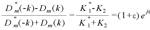
상기 <수학식 1>을 얻기 위한 과정을 설명하면, OFDM심볼의 서브캐리어 인덱스 k에서 수신신호는 <수학식 3>과 같이 표현되는데 여기서, k의 범위는 -(n/2)-1 부터 n/2까지로 FFT 인덱스를 의미하며, K1=(1/2)(1+(1+ε)exp(-jφ)), K2=(1/2)(1-(1+ε)exp(jφ)), ε는 I 채널과 Q 채널의 진폭 차, φ는 두 채널의 위상 차 Hm(k)는 서브캐리어 k의 채널, Sm(k)는 전송된 데이터 심볼, Nm(k)=K1Wm(k)+K2W* m(-k)(Wm(k))는 m번째 OFDM 심볼의 서브캐리어 인덱스 k에서 잡음을 각각 나타내고 있다. 그리고, I/Q 불균형 추정을 위해 또 다른 하나의 수식이 필요하게 되는데 즉, 같은 m번째 OFDM 심볼의 subcarrier k+l에서의 수식이 요구되며, 표현은 <수학식 4>와 같이 할 수 있다.The reception signal at the subcarrier index k of the OFDM symbol is expressed by Equation (3), where the range of k is - (n / 2) -1 to n / 2 means an FFT index, and K 1 = (1/2) (1+ (1 + ε) exp (-jφ)) and K 2 = (jφ)), ε is the I channel and the amplitude difference of the Q channel, φ is the phase difference between the two channels H m (k) is the sub-carrier k channels, S m (k) is the transmitted data symbol, N m (k ) = K 1 W m (k) + K 2 W * m (-k) (W m (k)) represents noise at the subcarrier index k of the m-th OFDM symbol. In order to estimate the I / Q imbalance, another equation is required. That is, an equation in the subcarrier k + 1 of the m-th OFDM symbol is required, and the expression can be expressed by Equation (4).
![]()
![]()
![]()
![]()
상기 <수학식 3>과 <수학식 4>로부터 I와 Q사이의 위상차와 진폭차와 관련있는 K1과 K2의 값을 얻기 위해 채널의 관련항목을 H1(k)=H1(k+l)=H(k)의 조건을 가정하고 두 연립 방정식의 해를 구하게 된다. 위의 채널 조건에 의해 미러(mirror)측면의 채널도 H1(-k)=H1(-k-l)=H(-k)의 가정이 성립된다. 먼저 상기 <수학식 3>과 <수학식 4>에서 오른쪽의 두 번째 항들을 없애면 K1에 대한 정보를 얻을 수 있다. 이것은 <수학식 5>와 <수학식 6>처럼 적절한 파일럿 신호의 값을 각각 양변에 곱하여 두 수식을 빼게 되면 K1H(k)에 관련된 값을 얻게 된다.In order to obtain the values of K 1 and K 2 related to the phase difference and the amplitude difference between I and Q from Equations (3) and (4), H 1 (k) = H 1 + l) = H (k), and solve the solution of both simultaneous equations. The channel condition on the mirror side also assumes H 1 (-k) = H 1 (-kl) = H (-k) by the above channel condition. First, information on K 1 can be obtained by eliminating the second term on the right side of Equation (3) and Equation (4). That is, when the values of the appropriate pilot signals are multiplied on both sides of Equation (5) and Equation (6), the values related to K 1 H (k) are obtained by subtracting the two equations.
![]()
![]()
![]()
![]()
즉, 정리하면 수학식 7과 같이 면 K1H(k)에 관련된 값이 얻어진다.That is, in summary, a value related to the surface K 1 H (k) is obtained as shown in Equation (7).

단, 상기 <수학식 7>은 분모가 0이 되지 않기 위해 <수학식 8>의 조건을 만족해야 한다.In Equation (7), since the denominator is not 0, the condition of Equation (8) must be satisfied.
![]()
![]()
또한, 상기 <수학식 3>과 <수학식 4>를 통해 방정식을 풀면 <수학식 9>를 얻을 수 있다.Equation (9) can be obtained by solving the equations through Equations (3) and (4).

여기서, I/Q 불균형 관련된 항목인 위상차와 진폭차에 관련된 것만 얻기 위해 상기 <수학식 8>과 <수학식 9>를 통해 <수학식 10>을 얻을 수 있다.Here, Equation (10) can be obtained by Equation (8) and Equation (9) to obtain only the phase difference and amplitude difference which are items related to the I / Q imbalance.

상기 <수학식 10>에서 N1과 N2는 잡음관련 항목으로 <수학식 11>과 같이 정리되므로 잡음전력은 같다.In Equation (10), N 1 and N 2 are noise related items, and the noise power is the same as Equation (11).


그러므로 상기 방법 1에서는 하나의 위상차와 진폭의 추정값을 얻기 위해 자신의 서브캐리어와 인접 서브캐리어, 그리고 상기 서브캐리어 들에 대한 mirrored 된 서브캐리어 두 개, 죽, 서브캐리어 인덱스 k, k+l, -k, -k-l의 4개의 수신된 프리앰블 데이터와 파일럿 톤의 정보가 필요함을 알 수 있다.Therefore, in the method 1, in order to obtain one phase difference and an estimated value of amplitude, two subcarriers, a subcarrier index k, k + l, and a mirrored subcarrier for the subcarriers, k, -kl, and the information of the pilot tone are required.
그리고 상기 <수학식10>의 결과에서 잡음이 없다면 <수학식 12>와 같이 위상차와 진폭에 관련된 항목으로 정리된다.If there is no noise in the result of Equation (10), the items are related to the phase difference and the amplitude as shown in Equation (12).

상기 <수학식 12>에서 a1 *(-k)는 <수학식 7>에 의해 <수학식 13>과 같이 얻어진다.In Equation (12), a 1 * (-k) is obtained as Equation (13) by Equation (7).

따라서 최종 예측된 진폭차와 위상차가 상기 <수학식1>과 같이 얻어지는 것이다.Therefore, the finally estimated amplitude difference and phase difference are obtained as shown in Equation (1).
또한, 상기 <수학식 2>를 얻기 위한 과정을 설명하면, 상기 방법 2의 프리앰블에 파일럿 톤이 DC에 대하여 대칭적으로 존재하지 않을 때에는 mirrored된 파일럿에는 값이 0인 널(null)값이 존재하기 때문에 널 서브캐리어 인덱스 k에서의 수신신호는 <수학식 14>와 같다If the pilot tone does not exist symmetrically with respect to the DC in the preamble of the
![]()
![]()
상기 <수학식 14>에서는 자기 신호가 0의 값이므로 K1에 관련된 항목은 없어지게 된다. 또한 파일럿이 있는 DC반대편의 서브캐리어 인덱스 -k에서는 <수학식 15>가 된다.In Equation (14), since the magnetic signal is a value of 0, the item related to K 1 is lost. In the subcarrier index -k on the opposite side of the DC with the pilot, Equation (15) is obtained.
![]()
![]()
따라서, 상기 <수학식 14>와 <수학식 15>를 통해 <수학식 16>이 얻어지게 된다.Therefore, Equation (16) is obtained through Equation (14) and Equation (15).
상기 <수학식 16으로 채널의 영향과 파일럿 신호의 게인 (gain)영향과 상관없이 I/Q 불균형을 추정할 수 있으며, 한 프리앰블에서 모든 파일럿을 평균하여 추정 에러를 줄인 진폭과 위상차는 <수학식 2>와 같이 예측된다.The I / Q imbalance can be estimated irrespective of the effect of the channel and the gain of the pilot signal, and the amplitude and the phase difference, which reduce the estimation error by averaging all the pilots in one preamble, 2>.
상기 평균 및 선택기(318)는 상기 방법 1의 경우 채널이득이 잡음의 전력보다 크고, 인접 파일럿 톤보다 상관성이 높은 추정값들만 평균을 산출하여 상기 적분기를 통해 I/Q 보상기에 출력하고, 방법 2의 경우 상기 채널이득이 잡음의 전력보다 큰 파일럿에 대한 추정값들만 평균을 산출하여 상기 I/Q 보상기에 출력한다. 여기서, 상기 방법 1의 경우 상기 <수학식 10>의 H*(-k)의 값이 잡음에 비해 작은 값을 가지게 되면 추정 오차가 매우 커지게 되므로 상기 채널추정기(328)에서 채널 추정 후, 채널 이득이 좋은 파일럿에 대한 것들만 포함시켜, 즉, <수학식 17>의 조 건을 만족하지 않는 항목은 제외하여 추정 에러를 낮춘다.In the method 1, the averaging and
![]()
![]()
여기서, σN는 잡음전력을 α는 어떤 실수값으로서 <수학식 1>의 계산시 선택되어지는 갯수를 조정할 수 있다. 또한, 상기 방법 1은 해를 얻을때 기본적으로 H1(k)=H1(k+l)=H(k)를 가정하였기 때문에 주파수 선택도가 큰 값을 갖게되는 서브캐리어들도 제외하여 성능향상을 가져올 수 있다. 즉, <수학식 18>을 만족하는 서브캐리어들만 선택하여 상기<수학식 1>에 적용할 수 있다.Where N is the noise power ? is a certain real number, and it is possible to adjust the number of items selected in the calculation of Equation (1). In the method 1, since the H 1 (k) = H 1 (k + 1) = H (k) is basically assumed, the subcarriers having a high frequency selectivity are excluded Improvement can be brought about. That is, only subcarriers satisfying Equation (18) can be selected and applied to Equation (1).
![]()
![]()
상기 <수학식 18>에서 β는 상관성을 의미하는 실수 값으로, 적절한 값을 사용하여 선택되는 수를 조절할 수 있다.In Equation (18),? Is a real value indicating correlation, and it is possible to adjust the number selected using an appropriate value.
또한, 방법 2에서도 <수학식 17>을 이용하여 잡음이 큰 부분의 파일럿들은 <수학식 2>의 과정에서 제외한다. 다시 말하면, 상기 방법 2는 널 캐리어에 간섭된 파일럿 톤의 값과 원래 자기 신호의 파일럿 톤인 널(null)값과 서로 비교하여 추정에러를 얻기 때문에 간섭 파일럿 톤들이 잡음보다 좋은 이득을 가져야만 추정에 오차를 줄일 수 있다.Also, in the
도 4는 본 발명의 실시 예에 따른 OFDM 수신기에서 I/Q 파라미터를 추정하기 위한 절차를 도시하고 있다.FIG. 4 illustrates a procedure for estimating I / Q parameters in an OFDM receiver according to an embodiment of the present invention.
상기 도 4를 참조하면, 먼저 401단계에서 상기 OFDM 수신기는 프리앰블에 파일럿 톤이 DC에 대하여 대칭적으로 존재하는지 검사한다. 여기서, 상기 프리앰블에 파일럿 톤이 DC에 대하여 대칭적으로 존재하는 것은 상기 도 1과 같이 파일럿신호가 DC를 중심으로 대칭형태로 존재하는 구조이고 상기 프리앰블에 파일럿 톤이 DC에 대하여 대칭적으로 존재하지 않는 경우는 상기 도 2와 같이 섹터별로 파일럿이 하나씩 이동되어 서로 간에 간섭을 받지 않는 구조이다.Referring to FIG. 4, in
만일, 상기 프리앰블에 파일럿 톤이 DC에 대하여 대칭적으로 존재하면, 상기 OFDM 수신기는 첫번째 방법으로 I/Q 불균형을 추정하기 위해 403단계로 진행하여 상기 <수학식 1>에 의해 진폭차(ε)와 위상차(φ)를 산출한다. If the pilot tone is symmetrically present in the preamble, the OFDM receiver proceeds to step 403 to estimate the I / Q imbalance as a first method, and calculates the amplitude difference? According to Equation (1) And the phase difference phi.
이후, 상기 OFDM 수신기는 405단계에서 수신된 OFDM 신호에 대한 채널 추정을 수행하고 407단계로 진행하여 채널 이득이 잡음의 전력보다 큰지 검사한다. 여기서, 상기 채널이득이 잡음의 전력보다 큰지 검사하는 것은 파일럿 신호의 크기가 잡음에 비해 작은 값을 가지게 되면 추정 오차가 매우 커지므로 상기 <수학식 17>의 조건을 만족하지 않는 항목은 제외하여 I/Q 불균형 보상기에 오차가 작은 추정값을 입력하기 위함이다.Thereafter, the OFDM receiver performs channel estimation on the OFDM signal received in
만일, 상기 채널 이득이 잡음의 전력보다 작으면, 상기 OFDM 수신기는 415단계로 진행하여 조건을 만족하지 않는 파일럿을 제외하고 410단계로 되돌아가 이하 단계를 수행한다.If the channel gain is less than the power of the noise, the OFDM receiver proceeds to step 415 and excludes pilots that do not satisfy the condition, and returns to step 410 to perform the following steps.
한편, 상기 채널 이득이 잡음의 전력보다 크면, 상기 OFDM 수신기는 408단계로 진행하여 수신되는 파일럿 신호가 인접 파일럿 신호와 상관성이 높은지 검사한다. 여기서, 수신되는 파일럿 신호가 인접 파일럿 신호와 상관성이 높은지 검사하는 것은 추정오차를 더욱 작게 하기 위함으로 상기 <수학식 18>의 조건을 만족하지 않는 항목, 즉, 상관성이 낮은 파일럿 톤을 제외하여 추정오차를 작게 하기 위함이다.On the other hand, if the channel gain is greater than the noise power, the OFDM receiver proceeds to step 408 to check whether the received pilot signal is highly correlated with the adjacent pilot signal. In order to further reduce the estimation error, it is possible to check whether the received pilot signal has a high correlation with the adjacent pilot signal, so that an item that does not satisfy the condition of Equation (18) This is to reduce the error.
만일, 상기 수신되는 파일럿 신호가 인접 파일럿 신호와 상관성이 낮으면, 상기 OFDM 수신기는 상기 415단계로 진행하여 이하 단계를 수행한다. 한편, 상기 수신되는 파일럿 신호가 인접 파일럿 신호와 상관성이 높으면, 상기 OFDM 수신기는 409단계에서 해당 파일럿 톤을 선택하고 410 단계로 진행하여 모든 파일럿 톤을 검사했는지 확인한다. If the received pilot signal has a low correlation with the adjacent pilot signal, the OFDM receiver proceeds to step 415 and performs the following steps. On the other hand, if the received pilot signal is highly correlated with the adjacent pilot signal, the OFDM receiver selects the corresponding pilot tone in
만일, 상기 모든 파일럿 톤을 검사하지 않았으면 상기 OFDM 수신기는 407 단계로 되돌아가 다른 파일럿 톤에 대한 검사를 수행한다. 한편, 상기 모든 파일럿 톤을 검사하였으면 상기 OFDM수신기는 411단계에서 상기 선택된 파일럿 톤에 대한 추정값들의 평균을 산출하고 413단계로 진행하여 I/Q 보상기에 산출된 평균을 입력한다. 이후, 상기 OFDM 수신기는 본 발명에 따른 알고리즘을 종료한다.If all the pilot tones have not been checked, the OFDM receiver returns to step 407 and performs another pilot tone check. On the other hand, if all the pilot tones have been checked, the OFDM receiver calculates an average of the estimated pilot tone values in
한편, 상기 401단계에서 상기 프리앰블에 파일럿 톤이 DC에 대하여 대칭적으로 존재하지 않으면, 상기 OFDM 수신기는 두번째 방법으로 I/Q 불균형을 추정하기 위해 416단계로 진행하여 <수학식 2>에 의해 진폭차(ε)와 위상차(φ)를 산출한다. If the pilot tone does not exist symmetrically with respect to DC in
이후, 상기 OFDM 수신기는 418단계에서 수신된 OFDM 신호에 대한 채널 추정 을 수행하고 407단계로 진행하여 채널 이득이 잡음의 전력보다 큰지 검사한다. 여기서, 상기 채널이득이 잡음의 전력보다 큰지 검사하는 것은 파일럿 신호의 크기가 잡음에 비해 작은 값을 가지게 되면 추정 오차가 매우 커지므로 조건을 만족하지 않는 항목은 제외하여 I/Q 불균형 보상기에 오차가 작은 추정값을 입력하기 위함이다.Then, the OFDM receiver performs channel estimation on the OFDM signal received in
만일, 상기 채널 이득이 잡음의 전력보다 작으면, 상기 OFDM 수신기는 426단계로 진행하여 조건을 만족하지 않는 파일럿을 제외하고 421 단계로 진행하여 이하 단계를 수행한다. If the channel gain is less than the power of the noise, the OFDM receiver proceeds to step 426 and excludes pilots that do not satisfy the condition, and proceeds to step 421 to perform the following steps.
한편, 상기 채널 이득이 잡음의 전력보다 크면, 상기 OFDM 수신기는 420단계로 진행하여 해당 파일럿 톤을 선택하고 421 단계에서 모든 파일럿 톤을 검사했는지 확인한다. 만일, 상기 모든 파일럿 톤을 검사하지 않았으면 상기 OFDM 수신기는 419단계로 되돌아가 다른 파일럿 톤에 대한 검사를 수행한다. 한편, 상기 모든 파일럿 톤을 검사하였으면 상기 OFDM수신기는 422단계로 진행하여 상기 선택된 파일럿에 대한 추정값들의 평균을 산출하고 424단계로 진행하여 I/Q 보상기에 산출된 평균을 입력한다. 이후, 상기 OFDM 수신기는 본 발명에 따른 알고리즘을 종료한다.On the other hand, if the channel gain is greater than the noise power, the OFDM receiver proceeds to step 420 and selects a corresponding pilot tone. In
도 5와 6은 현재 사용되고 있는 802.16e Moble WiMAX(와이브로)의 프리앰블을 사용하여 추정한 진폭과 위상 에러의 값을 보여주고 있다. 이 결과는 I/Q 불균형의 진폭에러가 10%이고 위상에러 5°일 때 컴퓨터 모의실험을 통하여 얻은 rms값을 나타낸 것이다. 와이브로에서는 도 2에서와 같이 l=3인 프리앰블을 사용하고 있 으나, 한 셀에는 세개의 섹터가 사용되므로 이들 섹터간에 간섭을 없애기 위해 프리앰블의 파일럿 톤들을 하나씩 이동하여 사용된다. 그러므로 세개의 섹터중 하나의 섹터에서만 DC를 중심으로 대칭으로 파일럿이 존재하여 상기 방법1이 사용되며, 나머지 두 섹터는 파일럿 대칭인 곳에 널 캐리어(null carrier)가 존재하게 되어 상기 방법 2가 사용된다. 5 and 6 show the values of the amplitude and phase error estimated using the preamble of the currently used 802.16e Moble WiMAX (WiBro). This result shows the rms value obtained by computer simulation when the amplitude error of the I / Q imbalance is 10% and the phase error is 5 °. In the WiBro, as shown in FIG. 2, the preamble with l = 3 is used. However, since three sectors are used in one cell, the pilot tones of the preamble are used by moving the pilot tones one by one in order to eliminate interference between the sectors. Therefore, the method 1 is used because there is a pilot symmetrically around DC in only one sector among the three sectors, and a null carrier exists in the other two sectors in a pilot symmetric manner, and the
상기 방법1을 사용한 결과를 살펴보면 상기 <수학식 17>과 <수학식 18>을 적용한 rms값이 작음을 알 수 있으며, 방법 2의 경우는 방법 1의 결과보다 그 폭이 더 크게 됨이 관찰할 수 있다. 이것은 와이브로에서는 l=3 이기 때문에 H1(k)=H1(k+3)=H(k)의 가정이 필요없는 방법 2가 더 좋은 성능을 보여주게 된다. 특히 낮은 SNR에서 <수학식 17>의 조건을 적용하면 큰 이득을 볼 수 있다.As a result of using the method 1, it can be seen that the rms values using the equations (17) and (18) are small, and in the case of the
한편 본 발명의 상세한 설명에서는 구체적인 실시 예에 관해 설명하였으나, 본 발명의 범위에서 벗어나지 않는 한도 내에서 여러 가지 변형이 가능함은 물론이다. 그러므로 본 발명의 범위는 설명된 실시 예에 국한되어 정해져서는 아니 되며 후술하는 특허청구의 범위뿐만 아니라 이 특허청구의 범위와 균등한 것들에 의해 정해져야 한다.While the present invention has been described in connection with what is presently considered to be the most practical and preferred embodiment, it is to be understood that the invention is not limited to the disclosed embodiments, but is capable of various modifications within the scope of the invention. Therefore, the scope of the present invention should not be limited by the illustrated embodiments, but should be determined by the scope of the appended claims and equivalents thereof.
도 1은 l=2인 OFDM의 프리앰블 구조를 도시하는 도면,1 is a diagram showing a preamble structure of OFDM with l = 2,
도 2는 l=3인 OFDM의 프리앰블 구조를 도시하는 도면,2 is a diagram showing a preamble structure of OFDM with l = 3,
도 3은 본 발명의 실시 예에 따른 OFDM 수신기에서 I/Q 파라미터를 추정하기 위한 블록구성을 도시하는 도면,3 is a block diagram for estimating an I / Q parameter in an OFDM receiver according to an embodiment of the present invention;
도 4는 본 발명의 실시 예에 따른 OFDM 수신기에서 I/Q 파라미터를 추정하기 위한 절차를 도시하는 도면,4 is a diagram illustrating a procedure for estimating an I / Q parameter in an OFDM receiver according to an embodiment of the present invention;
도 5와 6은 현재 사용되고 있는 802.16e Moble WiMAX(와이브로)의 프리앰블을 사용하여 추정한 진폭과 위상 에러의 값을 도시하는 도면.Figures 5 and 6 show values of amplitude and phase error estimated using the preamble of 802.16e Moble WiMAX (WiBro) currently in use.
Claims (16)


Priority Applications (6)
| Application Number | Priority Date | Filing Date | Title |
|---|---|---|---|
| KR1020080014749A KR101452995B1 (en) | 2008-02-19 | 2008-02-19 | Aparatus and method for estimation i/q mismatch parameter in ofdm receiver |
| US12/918,246 US8467479B2 (en) | 2008-02-19 | 2009-02-19 | Apparatus and method for estimating I/Q unbalance parameters in OFDM receiver |
| JP2010547563A JP5576300B2 (en) | 2008-02-19 | 2009-02-19 | Apparatus and method for estimating I / Q imbalance parameter in orthogonal frequency division multiplexing receiver |
| PCT/KR2009/000789 WO2009104909A2 (en) | 2008-02-19 | 2009-02-19 | Apparatus and method for estimating i/q unbalance parameters in ofdm receiver |
| EP09712702.1A EP2243266B1 (en) | 2008-02-19 | 2009-02-19 | Apparatus and method for estimating i/q unbalance parameters in ofdm receiver |
| CN200980105676.4A CN101946478B (en) | 2008-02-19 | 2009-02-19 | Apparatus and method for estimating i/q unbalance parameters in OFDM receiver |
Applications Claiming Priority (1)
| Application Number | Priority Date | Filing Date | Title |
|---|---|---|---|
| KR1020080014749A KR101452995B1 (en) | 2008-02-19 | 2008-02-19 | Aparatus and method for estimation i/q mismatch parameter in ofdm receiver |
Publications (2)
| Publication Number | Publication Date |
|---|---|
| KR20090089531A KR20090089531A (en) | 2009-08-24 |
| KR101452995B1 true KR101452995B1 (en) | 2014-10-23 |
Family
ID=40986051
Family Applications (1)
| Application Number | Title | Priority Date | Filing Date |
|---|---|---|---|
| KR1020080014749A KR101452995B1 (en) | 2008-02-19 | 2008-02-19 | Aparatus and method for estimation i/q mismatch parameter in ofdm receiver |
Country Status (6)
| Country | Link |
|---|---|
| US (1) | US8467479B2 (en) |
| EP (1) | EP2243266B1 (en) |
| JP (1) | JP5576300B2 (en) |
| KR (1) | KR101452995B1 (en) |
| CN (1) | CN101946478B (en) |
| WO (1) | WO2009104909A2 (en) |
Families Citing this family (15)
| Publication number | Priority date | Publication date | Assignee | Title |
|---|---|---|---|---|
| KR101278025B1 (en) | 2009-10-15 | 2013-06-21 | 한국전자통신연구원 | Receiving apparatus with OFDM I/Q imbalance compensation and method thereof |
| EP2337294B1 (en) * | 2009-12-21 | 2012-07-11 | TELEFONAKTIEBOLAGET LM ERICSSON (publ) | IQ-imbalance estimation for non-symmetrical pilot symbols |
| US9178675B2 (en) * | 2012-02-27 | 2015-11-03 | Intel Corporation | Channel estimation and tracking |
| US9647863B2 (en) | 2012-02-27 | 2017-05-09 | Intel Corporation | Techniques to manage dwell times for pilot rotation |
| CN103036846B (en) * | 2012-12-27 | 2015-09-09 | 上海创远仪器技术股份有限公司 | Be applied to the I/Q imbalance compensation control method of communication system receiver |
| US20140198865A1 (en) * | 2013-01-16 | 2014-07-17 | Qualcomm Incorporated | Ofdm pilot and frame structures |
| US9571324B2 (en) | 2013-07-23 | 2017-02-14 | Intel IP Corporation | Method for improving spectral efficiency in Wi-Fi OFDM systems |
| CN104981980B (en) | 2013-12-31 | 2017-04-19 | 华为技术有限公司 | Zero intermediate frequency correction method, device and equipment |
| US20170093458A1 (en) * | 2015-09-24 | 2017-03-30 | Qualcomm Incorporated | Online residual side band (rsb) calibration utilizing a frequency correction channel (fcch) |
| CN105791182B (en) * | 2016-03-10 | 2018-10-23 | 东南大学 | IQ imbalances and channel joint estimation method suitable for MIMO-OFDM systems |
| CN108123905B (en) * | 2017-12-20 | 2020-07-07 | 普联技术有限公司 | Estimation method, estimation device, estimation equipment and storage medium of IQ imbalance |
| KR102027674B1 (en) | 2018-01-12 | 2019-10-02 | 한국과학기술원 | Method and system for estimating i/q imbalance parameter of transceiver based on reinforcement learning |
| WO2019193641A1 (en) * | 2018-04-02 | 2019-10-10 | 三菱電機株式会社 | Wireless communication device |
| CN112054983B (en) * | 2020-08-21 | 2022-05-24 | 普联技术有限公司 | Signal amplitude processing method and device of OFDM receiver and terminal equipment |
| CN112887238B (en) * | 2021-05-06 | 2021-07-20 | 上海擎昆信息科技有限公司 | IQ imbalance correction method and device, and receiver |
Citations (2)
| Publication number | Priority date | Publication date | Assignee | Title |
|---|---|---|---|---|
| KR20030047591A (en) * | 2001-12-11 | 2003-06-18 | (주)텔레시스테크놀로지 | Device and method for compensating received signal of orthogonal frequency division multiplexing communication system |
| WO2004082232A1 (en) * | 2003-03-12 | 2004-09-23 | Koninklijke Philips Electronics N.V. | Transceiver with i/q mismatch compensation scheme |
Family Cites Families (18)
| Publication number | Priority date | Publication date | Assignee | Title |
|---|---|---|---|---|
| JP4039733B2 (en) * | 1998-05-15 | 2008-01-30 | 三菱電機株式会社 | Carrier frequency synchronization circuit |
| AU2002321694A1 (en) * | 2002-08-02 | 2004-02-25 | Nokia Corporation | Quadrature demodulator using a fft-processor |
| US7298793B2 (en) * | 2003-08-21 | 2007-11-20 | Mediatek Inc. | Method and apparatus for I/Q mismatch calibration of transmitter |
| US7570923B2 (en) * | 2004-05-18 | 2009-08-04 | Agere Systems Inc. | I/Q compensation of frequency dependent response mismatch in a pair of analog low-pass filters |
| US7466768B2 (en) * | 2004-06-14 | 2008-12-16 | Via Technologies, Inc. | IQ imbalance compensation |
| KR100606130B1 (en) * | 2005-02-17 | 2006-07-28 | 삼성전자주식회사 | Optimum i/q imbalance compensator in zero-if ofdm receiver and method therefor |
| US7474711B2 (en) * | 2005-05-06 | 2009-01-06 | Motorola, Inc | Method and system for I/Q imbalance and DC offset correction |
| JP2007142674A (en) * | 2005-11-16 | 2007-06-07 | Matsushita Electric Ind Co Ltd | Multicarrier transmitter, multicarrier receiver, and communication method |
| JP4406398B2 (en) | 2005-12-26 | 2010-01-27 | 株式会社東芝 | OFDM signal transmission method and transmitter, and OFDM signal receiver |
| JP4550746B2 (en) | 2006-02-01 | 2010-09-22 | 株式会社東芝 | Wireless communication method using OFDM, OFDM transmitter and OFDM receiver |
| KR100896203B1 (en) * | 2006-02-24 | 2009-05-12 | 삼성전자주식회사 | Apparatus and method for channel estimation for data demodulation in broadband wireless access system |
| JP4213734B2 (en) * | 2006-07-05 | 2009-01-21 | 株式会社東芝 | Wireless communication method and OFDM receiver using OFDM |
| US8503545B2 (en) * | 2006-08-31 | 2013-08-06 | Advanced Micro Devices, Inc. | I/Q imbalance compensation |
| JP4261578B2 (en) * | 2006-12-27 | 2009-04-30 | 株式会社東芝 | Wireless communication apparatus and reception method |
| JP2008283288A (en) * | 2007-05-08 | 2008-11-20 | Toshiba Corp | Radio transmission device and method |
| JP4421635B2 (en) * | 2007-06-18 | 2010-02-24 | 株式会社東芝 | Wireless communication method and wireless communication device |
| US20090122918A1 (en) * | 2007-11-06 | 2009-05-14 | Augusta Technology, Inc. | Methods for Compensating for I/Q Imbalance in OFDM Systems |
| JP2009147498A (en) * | 2007-12-12 | 2009-07-02 | Sharp Corp | Transmitter, control method and program of transmitter, receiver, control method and program of receiver, and wireless communication system |
-
2008
- 2008-02-19 KR KR1020080014749A patent/KR101452995B1/en active IP Right Grant
-
2009
- 2009-02-19 CN CN200980105676.4A patent/CN101946478B/en not_active Expired - Fee Related
- 2009-02-19 EP EP09712702.1A patent/EP2243266B1/en not_active Not-in-force
- 2009-02-19 WO PCT/KR2009/000789 patent/WO2009104909A2/en active Application Filing
- 2009-02-19 US US12/918,246 patent/US8467479B2/en active Active
- 2009-02-19 JP JP2010547563A patent/JP5576300B2/en not_active Expired - Fee Related
Patent Citations (2)
| Publication number | Priority date | Publication date | Assignee | Title |
|---|---|---|---|---|
| KR20030047591A (en) * | 2001-12-11 | 2003-06-18 | (주)텔레시스테크놀로지 | Device and method for compensating received signal of orthogonal frequency division multiplexing communication system |
| WO2004082232A1 (en) * | 2003-03-12 | 2004-09-23 | Koninklijke Philips Electronics N.V. | Transceiver with i/q mismatch compensation scheme |
Also Published As
| Publication number | Publication date |
|---|---|
| KR20090089531A (en) | 2009-08-24 |
| US20100329394A1 (en) | 2010-12-30 |
| WO2009104909A2 (en) | 2009-08-27 |
| EP2243266B1 (en) | 2018-09-26 |
| EP2243266A4 (en) | 2017-04-26 |
| JP2011512770A (en) | 2011-04-21 |
| JP5576300B2 (en) | 2014-08-20 |
| CN101946478B (en) | 2014-01-01 |
| EP2243266A2 (en) | 2010-10-27 |
| WO2009104909A3 (en) | 2009-10-22 |
| US8467479B2 (en) | 2013-06-18 |
| CN101946478A (en) | 2011-01-12 |
Similar Documents
| Publication | Publication Date | Title |
|---|---|---|
| KR101452995B1 (en) | Aparatus and method for estimation i/q mismatch parameter in ofdm receiver | |
| US8737533B2 (en) | Method and arrangements for estimating IQ-imbalance | |
| US6625111B1 (en) | OFDM communication apparatus | |
| US8971465B2 (en) | Receiver-side estimation of and compensation for signal impairments | |
| JP2010525710A (en) | IQ imbalance correction method and apparatus in OFDM receiver | |
| US20110051790A1 (en) | Radio communication device and method | |
| CN108696305B (en) | High-precision frequency offset measurement method suitable for LTE-A MIMO signal analysis system | |
| US20030104797A1 (en) | Soft decision gain compensation for receive filter attenuation | |
| US20150117577A1 (en) | Wireless communication receiver with i/q imbalance estimation and correction techniques | |
| JP5536042B2 (en) | Method for estimating residual frequency error in a communication system | |
| JP2001086092A (en) | Ofdm communications equipment and detecting method | |
| KR20090075726A (en) | Reception method and reception device | |
| TW201635765A (en) | Association estimation compensation method for solving radio-frequency imperfection in uplink transmission system | |
| JP5318207B2 (en) | Frequency domain multiplexed signal receiving method and frequency domain multiplexed signal receiving apparatus | |
| KR20090123980A (en) | Calibration method for non-ideal transceivers | |
| Horlin et al. | Low-complexity EM-based joint acquisition of the carrier frequency offset and IQ imbalance | |
| JP5147089B2 (en) | A method for determining a hybrid domain compensation parameter of analog loss in an OFDM communication system and a compensation method. | |
| EP2337294B1 (en) | IQ-imbalance estimation for non-symmetrical pilot symbols | |
| WO2006116453A1 (en) | Antenna array calibration for wireless communication systems | |
| Horlin et al. | Low-complexity EM-based joint CFO and IQ imbalance acquisition | |
| JP2018133740A (en) | Radio communication device, phase noise correction method, and radio communication system | |
| KR101097295B1 (en) | Self Estimation and Compensation scheme for IQ Imbalance of Direct Conversion Transceiver in OFDM system | |
| KR20030088813A (en) | Estimation and compensaion method of I/Q mismatch and DC offset | |
| JP2007506310A (en) | Apparatus and method for adaptive orthogonality correction |
Legal Events
| Date | Code | Title | Description |
|---|---|---|---|
| A201 | Request for examination | ||
| E902 | Notification of reason for refusal | ||
| E701 | Decision to grant or registration of patent right | ||
| GRNT | Written decision to grant | ||
| FPAY | Annual fee payment |
Payment date: 20170927 Year of fee payment: 4 |
|
| FPAY | Annual fee payment |
Payment date: 20180921 Year of fee payment: 5 |