KR101426627B1 - Tissue closure devices, device and systems for delivery, kits and methods therefor - Google Patents
Tissue closure devices, device and systems for delivery, kits and methods therefor Download PDFInfo
- Publication number
- KR101426627B1 KR101426627B1 KR1020127014579A KR20127014579A KR101426627B1 KR 101426627 B1 KR101426627 B1 KR 101426627B1 KR 1020127014579 A KR1020127014579 A KR 1020127014579A KR 20127014579 A KR20127014579 A KR 20127014579A KR 101426627 B1 KR101426627 B1 KR 101426627B1
- Authority
- KR
- South Korea
- Prior art keywords
- clip
- stem
- plug
- tissue
- deployment
- Prior art date
Links
Images


Classifications
-
- A—HUMAN NECESSITIES
- A61—MEDICAL OR VETERINARY SCIENCE; HYGIENE
- A61B—DIAGNOSIS; SURGERY; IDENTIFICATION
- A61B17/00—Surgical instruments, devices or methods, e.g. tourniquets
- A61B17/04—Surgical instruments, devices or methods, e.g. tourniquets for suturing wounds; Holders or packages for needles or suture materials
-
- A—HUMAN NECESSITIES
- A61—MEDICAL OR VETERINARY SCIENCE; HYGIENE
- A61B—DIAGNOSIS; SURGERY; IDENTIFICATION
- A61B17/00—Surgical instruments, devices or methods, e.g. tourniquets
- A61B17/0057—Implements for plugging an opening in the wall of a hollow or tubular organ, e.g. for sealing a vessel puncture or closing a cardiac septal defect
-
- A—HUMAN NECESSITIES
- A61—MEDICAL OR VETERINARY SCIENCE; HYGIENE
- A61B—DIAGNOSIS; SURGERY; IDENTIFICATION
- A61B17/00—Surgical instruments, devices or methods, e.g. tourniquets
- A61B17/11—Surgical instruments, devices or methods, e.g. tourniquets for performing anastomosis; Buttons for anastomosis
-
- A—HUMAN NECESSITIES
- A61—MEDICAL OR VETERINARY SCIENCE; HYGIENE
- A61B—DIAGNOSIS; SURGERY; IDENTIFICATION
- A61B17/00—Surgical instruments, devices or methods, e.g. tourniquets
- A61B17/34—Trocars; Puncturing needles
-
- A—HUMAN NECESSITIES
- A61—MEDICAL OR VETERINARY SCIENCE; HYGIENE
- A61M—DEVICES FOR INTRODUCING MEDIA INTO, OR ONTO, THE BODY; DEVICES FOR TRANSDUCING BODY MEDIA OR FOR TAKING MEDIA FROM THE BODY; DEVICES FOR PRODUCING OR ENDING SLEEP OR STUPOR
- A61M25/00—Catheters; Hollow probes
- A61M25/01—Introducing, guiding, advancing, emplacing or holding catheters
-
- A—HUMAN NECESSITIES
- A61—MEDICAL OR VETERINARY SCIENCE; HYGIENE
- A61B—DIAGNOSIS; SURGERY; IDENTIFICATION
- A61B17/00—Surgical instruments, devices or methods, e.g. tourniquets
- A61B17/064—Surgical staples, i.e. penetrating the tissue
- A61B17/0644—Surgical staples, i.e. penetrating the tissue penetrating the tissue, deformable to closed position
-
- A—HUMAN NECESSITIES
- A61—MEDICAL OR VETERINARY SCIENCE; HYGIENE
- A61B—DIAGNOSIS; SURGERY; IDENTIFICATION
- A61B17/00—Surgical instruments, devices or methods, e.g. tourniquets
- A61B17/32—Surgical cutting instruments
-
- A—HUMAN NECESSITIES
- A61—MEDICAL OR VETERINARY SCIENCE; HYGIENE
- A61B—DIAGNOSIS; SURGERY; IDENTIFICATION
- A61B17/00—Surgical instruments, devices or methods, e.g. tourniquets
- A61B17/32—Surgical cutting instruments
- A61B17/3209—Incision instruments
-
- A—HUMAN NECESSITIES
- A61—MEDICAL OR VETERINARY SCIENCE; HYGIENE
- A61B—DIAGNOSIS; SURGERY; IDENTIFICATION
- A61B18/00—Surgical instruments, devices or methods for transferring non-mechanical forms of energy to or from the body
- A61B18/04—Surgical instruments, devices or methods for transferring non-mechanical forms of energy to or from the body by heating
- A61B18/12—Surgical instruments, devices or methods for transferring non-mechanical forms of energy to or from the body by heating by passing a current through the tissue to be heated, e.g. high-frequency current
- A61B18/14—Probes or electrodes therefor
- A61B18/1482—Probes or electrodes therefor having a long rigid shaft for accessing the inner body transcutaneously in minimal invasive surgery, e.g. laparoscopy
-
- A—HUMAN NECESSITIES
- A61—MEDICAL OR VETERINARY SCIENCE; HYGIENE
- A61B—DIAGNOSIS; SURGERY; IDENTIFICATION
- A61B17/00—Surgical instruments, devices or methods, e.g. tourniquets
- A61B2017/00477—Coupling
-
- A—HUMAN NECESSITIES
- A61—MEDICAL OR VETERINARY SCIENCE; HYGIENE
- A61B—DIAGNOSIS; SURGERY; IDENTIFICATION
- A61B17/00—Surgical instruments, devices or methods, e.g. tourniquets
- A61B17/0057—Implements for plugging an opening in the wall of a hollow or tubular organ, e.g. for sealing a vessel puncture or closing a cardiac septal defect
- A61B2017/00575—Implements for plugging an opening in the wall of a hollow or tubular organ, e.g. for sealing a vessel puncture or closing a cardiac septal defect for closure at remote site, e.g. closing atrial septum defects
- A61B2017/00615—Implements with an occluder on one side of the opening and holding means therefor on the other
-
- A—HUMAN NECESSITIES
- A61—MEDICAL OR VETERINARY SCIENCE; HYGIENE
- A61B—DIAGNOSIS; SURGERY; IDENTIFICATION
- A61B17/00—Surgical instruments, devices or methods, e.g. tourniquets
- A61B17/0057—Implements for plugging an opening in the wall of a hollow or tubular organ, e.g. for sealing a vessel puncture or closing a cardiac septal defect
- A61B2017/00575—Implements for plugging an opening in the wall of a hollow or tubular organ, e.g. for sealing a vessel puncture or closing a cardiac septal defect for closure at remote site, e.g. closing atrial septum defects
- A61B2017/00623—Introducing or retrieving devices therefor
-
- A—HUMAN NECESSITIES
- A61—MEDICAL OR VETERINARY SCIENCE; HYGIENE
- A61B—DIAGNOSIS; SURGERY; IDENTIFICATION
- A61B17/00—Surgical instruments, devices or methods, e.g. tourniquets
- A61B17/0057—Implements for plugging an opening in the wall of a hollow or tubular organ, e.g. for sealing a vessel puncture or closing a cardiac septal defect
- A61B2017/00646—Type of implements
- A61B2017/00659—Type of implements located only on one side of the opening
-
- A—HUMAN NECESSITIES
- A61—MEDICAL OR VETERINARY SCIENCE; HYGIENE
- A61B—DIAGNOSIS; SURGERY; IDENTIFICATION
- A61B17/00—Surgical instruments, devices or methods, e.g. tourniquets
- A61B17/0057—Implements for plugging an opening in the wall of a hollow or tubular organ, e.g. for sealing a vessel puncture or closing a cardiac septal defect
- A61B2017/00646—Type of implements
- A61B2017/00668—Type of implements the implement being a tack or a staple
-
- A—HUMAN NECESSITIES
- A61—MEDICAL OR VETERINARY SCIENCE; HYGIENE
- A61B—DIAGNOSIS; SURGERY; IDENTIFICATION
- A61B17/00—Surgical instruments, devices or methods, e.g. tourniquets
- A61B17/0057—Implements for plugging an opening in the wall of a hollow or tubular organ, e.g. for sealing a vessel puncture or closing a cardiac septal defect
- A61B2017/00672—Locating means therefor, e.g. bleed back lumen
-
- A—HUMAN NECESSITIES
- A61—MEDICAL OR VETERINARY SCIENCE; HYGIENE
- A61B—DIAGNOSIS; SURGERY; IDENTIFICATION
- A61B17/00—Surgical instruments, devices or methods, e.g. tourniquets
- A61B17/04—Surgical instruments, devices or methods, e.g. tourniquets for suturing wounds; Holders or packages for needles or suture materials
- A61B17/0401—Suture anchors, buttons or pledgets, i.e. means for attaching sutures to bone, cartilage or soft tissue; Instruments for applying or removing suture anchors
- A61B2017/0446—Means for attaching and blocking the suture in the suture anchor
- A61B2017/0461—Means for attaching and blocking the suture in the suture anchor with features cooperating with special features on the suture, e.g. protrusions on the suture
- A61B2017/0462—One way system, i.e. also tensioning the suture
-
- A—HUMAN NECESSITIES
- A61—MEDICAL OR VETERINARY SCIENCE; HYGIENE
- A61B—DIAGNOSIS; SURGERY; IDENTIFICATION
- A61B17/00—Surgical instruments, devices or methods, e.g. tourniquets
- A61B17/064—Surgical staples, i.e. penetrating the tissue
- A61B2017/0641—Surgical staples, i.e. penetrating the tissue having at least three legs as part of one single body
-
- A—HUMAN NECESSITIES
- A61—MEDICAL OR VETERINARY SCIENCE; HYGIENE
- A61B—DIAGNOSIS; SURGERY; IDENTIFICATION
- A61B18/00—Surgical instruments, devices or methods for transferring non-mechanical forms of energy to or from the body
- A61B2018/00315—Surgical instruments, devices or methods for transferring non-mechanical forms of energy to or from the body for treatment of particular body parts
- A61B2018/00345—Vascular system
- A61B2018/00404—Blood vessels other than those in or around the heart
- A61B2018/00422—Angioplasty
-
- A—HUMAN NECESSITIES
- A61—MEDICAL OR VETERINARY SCIENCE; HYGIENE
- A61B—DIAGNOSIS; SURGERY; IDENTIFICATION
- A61B18/00—Surgical instruments, devices or methods for transferring non-mechanical forms of energy to or from the body
- A61B2018/00571—Surgical instruments, devices or methods for transferring non-mechanical forms of energy to or from the body for achieving a particular surgical effect
- A61B2018/00601—Cutting
-
- A—HUMAN NECESSITIES
- A61—MEDICAL OR VETERINARY SCIENCE; HYGIENE
- A61B—DIAGNOSIS; SURGERY; IDENTIFICATION
- A61B18/00—Surgical instruments, devices or methods for transferring non-mechanical forms of energy to or from the body
- A61B2018/0091—Handpieces of the surgical instrument or device
- A61B2018/00916—Handpieces of the surgical instrument or device with means for switching or controlling the main function of the instrument or device
-
- A—HUMAN NECESSITIES
- A61—MEDICAL OR VETERINARY SCIENCE; HYGIENE
- A61B—DIAGNOSIS; SURGERY; IDENTIFICATION
- A61B18/00—Surgical instruments, devices or methods for transferring non-mechanical forms of energy to or from the body
- A61B18/04—Surgical instruments, devices or methods for transferring non-mechanical forms of energy to or from the body by heating
- A61B18/12—Surgical instruments, devices or methods for transferring non-mechanical forms of energy to or from the body by heating by passing a current through the tissue to be heated, e.g. high-frequency current
- A61B18/14—Probes or electrodes therefor
- A61B2018/1405—Electrodes having a specific shape
- A61B2018/1412—Blade
-
- A—HUMAN NECESSITIES
- A61—MEDICAL OR VETERINARY SCIENCE; HYGIENE
- A61B—DIAGNOSIS; SURGERY; IDENTIFICATION
- A61B18/00—Surgical instruments, devices or methods for transferring non-mechanical forms of energy to or from the body
- A61B18/04—Surgical instruments, devices or methods for transferring non-mechanical forms of energy to or from the body by heating
- A61B18/12—Surgical instruments, devices or methods for transferring non-mechanical forms of energy to or from the body by heating by passing a current through the tissue to be heated, e.g. high-frequency current
- A61B18/14—Probes or electrodes therefor
- A61B18/1442—Probes having pivoting end effectors, e.g. forceps
- A61B2018/1452—Probes having pivoting end effectors, e.g. forceps including means for cutting
- A61B2018/1455—Probes having pivoting end effectors, e.g. forceps including means for cutting having a moving blade for cutting tissue grasped by the jaws
-
- A—HUMAN NECESSITIES
- A61—MEDICAL OR VETERINARY SCIENCE; HYGIENE
- A61B—DIAGNOSIS; SURGERY; IDENTIFICATION
- A61B90/00—Instruments, implements or accessories specially adapted for surgery or diagnosis and not covered by any of the groups A61B1/00 - A61B50/00, e.g. for luxation treatment or for protecting wound edges
- A61B90/03—Automatic limiting or abutting means, e.g. for safety
- A61B2090/033—Abutting means, stops, e.g. abutting on tissue or skin
- A61B2090/036—Abutting means, stops, e.g. abutting on tissue or skin abutting on tissue or skin
-
- A—HUMAN NECESSITIES
- A61—MEDICAL OR VETERINARY SCIENCE; HYGIENE
- A61B—DIAGNOSIS; SURGERY; IDENTIFICATION
- A61B90/00—Instruments, implements or accessories specially adapted for surgery or diagnosis and not covered by any of the groups A61B1/00 - A61B50/00, e.g. for luxation treatment or for protecting wound edges
- A61B90/03—Automatic limiting or abutting means, e.g. for safety
- A61B2090/037—Automatic limiting or abutting means, e.g. for safety with a frangible part, e.g. by reduced diameter
-
- A—HUMAN NECESSITIES
- A61—MEDICAL OR VETERINARY SCIENCE; HYGIENE
- A61B—DIAGNOSIS; SURGERY; IDENTIFICATION
- A61B50/00—Containers, covers, furniture or holders specially adapted for surgical or diagnostic appliances or instruments, e.g. sterile covers
- A61B50/30—Containers specially adapted for packaging, protecting, dispensing, collecting or disposing of surgical or diagnostic appliances or instruments
Abstract
본 발명은 조직 봉합 장치, 이송용 장치 및 시스템, 키트 및 이를 위한 방법에 관한 것이다. 상기 조직 봉합 장치는 압박을 대신하여 조직 봉합을 달성할 수 있으며, 도입장치에 의해 또는 체외로부터 신속하게 전개 가능하도록 구성될 수 있다.The present invention relates to a tissue sealing device, a transferring device and system, a kit and a method therefor. The tissue sealing device can achieve tissue sealing in place of compression, and can be configured to be rapidly deployable by an introducer or from the outside of the body.
Description
상호 참조Cross-reference
본 출원은 2009년 11월 9일자로 출원된 발명의 명칭이 "생흡수성 플러그 조직 봉합 시스템(Bioabsorbable Plug Tissue Closure System)"인 미국 가특허 출원 제61/280,896호의 우선권을 주장하며, 또한 2010년 4월 9일자로 출원된 발명의 명칭이 "조직 봉합 장치, 이송용 장치 및 시스템, 키트 그리고 이를 위한 방법(Tissue Closure Devices, Device and Systems for Delivery, Kits and Methods Therefor)"인 미국 특허 출원 제12/757,275호의 부분 계속 출원이고 상기 미국 특허 출원에 대한 우선권을 주장하는데, 상기 미국 특허 출원 제12/757,275호는 2009년 4월 9일자로 출원된 발명의 명칭이 "의료 장치의 비외상성 이송을 위한 도입장치 시스 어댑터(Introducer Sheath Adapter for the Atraumatic Delivery of a Medical Device)"인 미국 가특허 출원 제61/212,296호, 2009년 9월 21일자로 출원된 발명의 명칭이 "조직 봉합 장치 시스템 및 방법(Tissue Closure Device Systems and Methods)"인 미국 가특허 출원 제61/277,359호, 및 2009년 11월 9일자로 출원된 발명의 명칭이 "생흡수성 플러그 조직 봉합 시스템(Bioabsorbable Plug Tissue Closure System)"인 미국 가특허 출원 제61/280,896호의 우선권을 주장하고, 2008년 12월 3일자로 출원된 발명의 명칭이 "안내식 조직 절단 장치, 방법 및 이용 방법 그리고 이를 위한 키트(Guided Tissue Cutting Device, Methods, of Use and Kits Therefor)"인 미국 특허 출원 제12/327,655호의 부분 계속 출원이고, 상기 미국 특허 출원 제12/327,655호는 2008년 10월 31일자로 출원된 발명의 명칭이 "혈관 봉합 장치, 시스템 및 그 이용 방법(Vascular Closure Devices, Systems, and Methods of Use)"인 미국 특허 출원 제12/263,322호의 계속 출원이고, 상기 미국 특허 출원 제12/263,322호는 2007년 12월 3일자로 출원된 발명의 명칭이 "안내식 조직 절단 장치 및 그 이용 방법(Guided Tissue Cutting Device and Method of Use)"인 미국 우선권 특허 출원 제61/005,435호, 및 2008년 8월 26일자로 출원된 발명의 명칭이 "조직 봉합 장치, 시스템 및 그 이용 방법(Tissue Closure Devices, Systems and Methods of Use)"인 미국 우선권 특허 출원 제61/190,100호의 우선권을 주장하고 또한 2002년 6월 28일자로 제출되어 현재는 미국 특허 제6,726,696호인 미국 특허 출원 제10/183,396호의 부분 계속 출원이며, 상기 미국 특허 출원 제10/183,396호는 2002년 4월 23일자로 제출된 발명의 명칭이 "동맥절개부 봉합 장치 및 기술(Arteriotomy Closure Devices and Techniques)"인 미국 특허 출원 제10/127,714호의 부분 계속 출원이며 2001년 4월 24일자로 출원된 발명의 명칭이 "경피성 혈관 액세스 봉합 장치 및 방법(Percutaneous Vessel Access Closure Device and Method)"인 특허 출원 제60/286,269호 및 2001년 6월 25일자로 출원된 발명의 명칭이 "경피성 혈관 액세스 봉합 장치 및 방법(Percutaneous Vessel Access Closure Device and Method)"인 특허 출원 제60/300,892호, 및 2001년 6월 28일자로 출원된 발명의 명칭이 "경피성 혈관 액세스 봉합 장치 및 방법(지혈 패치 또는 칼라)[Percutaneous Vessel Access Closure Device and Method (Hemostatic Patch or Collar)]"인 특허 출원 제60/302,255호의 우선권을 주장하며, 이들의 개시내용은 인용함으로써 그 전체 내용이 본 명세서에 포함되며 본 명세서의 일부를 형성한다.This application claims priority from U.S. Provisional Patent Application No. 61 / 280,896 entitled " Bioabsorbable Plug Tissue Closure System "filed November 9, 2009, Filed on September 9, entitled " Tissue Closure Devices, Devices and Systems for Delivery, Kits and Methods Therefor, " This application is a continuation-in-part of US patent application Ser. No. 757,275, which claims the benefit of US patent application Ser. No. 12 / 757,275, entitled "Introduction for Non- Traumatic Transfer of Medical Devices, filed April 9, US Patent Application No. 61 / 212,296, entitled " Introducer Sheath Adapter for the Atraumatic Delivery of a Medical Device, " filed on September 21, 2009, entitled " And US Patent Application No. 61 / 277,359 entitled " Tissue Closure Device Systems and Methods ", filed November 9, 2009, entitled "Bioabsorbable Plug Tissue Closure System "Quot;, filed on December 3, 2008, entitled "Guided Tissue Cutting Device, Method and Method of Use, and Kit (Guided Tissue Cutting Device, No. 12 / 327,655, filed on October 31, 2008, entitled "Methods of Use and Kits Therefor ", which is a continuation-in-part of U.S. Patent Application No. 12 / 327,655, 12 / 263,322, filed December 3, 2007, which is a continuation-in-part of U.S. Patent Application No. 12 / 263,322, entitled " Vascular Closure Devices, Systems, and Methods of Use &Quot; guiding formula " United States Priority 61 / 005,435 entitled " Guided Tissue Cutting Device and Method of Use "filed on August 26, 2008 and entitled" US Priority 61 / 190,100, filed June 28, 2002, now U.S. Patent No. 6,726,696, entitled " Tissue Closure Devices, Systems and Methods of Use " No. 10 / 183,396, filed on April 23, 2002, entitled " Arteriotomy Closure Devices and Techniques ", filed on April 23,2002, A patent application No. 60/286, entitled " Percutaneous Vessel Access Closure Device and Method "filed on April 24, 2001, which is a continuation-in-part of patent application No. 10 / 127,714, , No. 60 / 300,892 entitled " Percutaneous Vessel Access Closure Device and Method ", filed June 25, 2001, and June 28, 2001, entitled " Prior Art Claim 60 / 302,255, entitled " Percutaneous Vessel Access Closure Device and Method, "entitled " Percutaneous Vessel Access Closure Device and Method, , The disclosures of which are incorporated herein by reference in their entirety and form part of this disclosure.
기술 분야Technical field
본 발명은 일반적으로 의료 장치 및 기법에 관한 것이며, 더욱 구체적으로는 심혈관 조직 봉합 장치, 시스템, 기법 및 키트에 관한 것이다.The present invention relates generally to medical devices and techniques, and more particularly to cardiovascular tissue sealing devices, systems, techniques and kits.
대부분의 심장학 및 영상의학 과정에 있어서, 카테터가 동맥, 예컨대 대퇴부 동맥과 같은 동맥에 혈관 도입장치를 통해 삽입된다. 이러한 과정이 완료되면, 내과의사는 도입장치로부터 카테터를 제거하고, 다음으로 혈관에서의 루멘(lumen) 내로의 개구 또는 절개부 또는 동맥절개부로부터 도입장치를 제거한다. 내과의사는 다음으로, 환자가 퇴원할 수 있도록 하기 위해 동맥절개부를 통해 유출되는 혈액의 양을 제한해야만 하거나 혈액의 유출을 방지해야만 한다. 내과의사는 현재 동맥절개부의 봉합을 위해 다수의 방법, 예컨대 국부 압박법, 봉합, 콜라겐 플러그, 접착제, 겔, 포옴(foam), 클립, 및 유사한 재료를 이용하고 있다.In most cardiology and radiology procedures, a catheter is inserted through an angiostatic device into an artery, such as an artery, such as the femoral artery. Upon completion of this procedure, the physician removes the catheter from the introducer device and then removes the introducer device from the opening or incision into the lumen in the vessel or from the arterial incision. The physician should then either limit the amount of blood flowing through the arterial incision to prevent the patient from discharging blood or allow blood to escape so that the patient can be discharged. The physician currently uses a number of methods, such as local compression, sutures, collagen plugs, adhesives, gels, foams, clips, and similar materials, for the suturing of the arterial incisions.
국부 압박법을 행함에 있어서, 내과의사는 혈관에 대해 아래로 눌러 동맥절개부가 자연적으로 응혈되도록 한다. 그러나, 이러한 방법은 상당한 시간이 소요될 수 있으며, 움직이지 않는 상태로 관찰을 위해 병원 내에 있을 것을 환자에게 요구한다. 더욱이, 구멍 위치에서의 응혈은 또한 떨어질 수 있다. 국부 압박을 위해 필요한 시간은 전술한 과정에서 사용된 헤라핀, 당단백 IIb/IIA 길항제 또는 다른 응혈방지제의 양에 따라 현저하게 연장될 수 있다. 봉합 및 콜라겐 플러그는 과정의 가변성이 있을 수 있으며, 혈관을 봉합하기 위해 시간을 필요로 할 수 있고, 별도의 전개 장치를 필요로 할 수 있다. 접착제, 겔, 포옴 및 클립은 부정적인 비용 인자가 있을 수 있으며, 복잡한 전개 프로세스를 필요로 할 수 있고, 과정의 가변성이 있을 수 있다.In performing the local compression method, the internal surgeon pushes down against the blood vessel to allow the arterial incision to naturally coagulate. However, this method can take a considerable amount of time and requires the patient to be in the hospital for observation in an immobile state. Moreover, clotting at the hole position can also fall. The time required for local compression can be significantly prolonged depending on the amount of herapine, glycoprotein IIb / IIA antagonist or other anticoagulant used in the procedure described above. Sutures and collagen plugs may be process variable, may require time to suture vessels, and may require separate deployment devices. Adhesives, gels, foams and clips may have negative cost factors, may require complex development processes, and may have process variability.
본 개시내용의 양태는 봉합 장치에 관한 것이다. 상기 봉합 장치는, 가요성 원위(distal flexible) 캡을 포함하며; 근위에(proximally) 위치설정되는 하나 이상의 반경방향 연장 요소(radial extending element); 상기 가요성 원위 캡과 하나 이상의 반경방향 연장 요소 사이에 위치설정되는 스템(stem)을 구비할 수 있으며, 상기 가요성 원위 캡은 축선을 향해 형성 가능하다. 적어도 일부 구성에 있어서, 가요성 원위 캡은 실질상 평평한 원위면(distal surface) 및 실질상 평평한 근위면(proximal surface), 실질상 평평한 원위면 및 실질상 오목한 근위면, 실질상 평평한 원위면 및 실질상 볼록한 근위면, 실질상 볼록한 원위면 및 실질상 평평한 근위면, 실질상 볼록한 원위면 및 실질상 볼록한 근위면, 실질상 볼록한 원위면 및 실질상 오목한 근위면, 실질상 오목한 원위면 및 실질상 평평한 근위면, 실질상 오목한 원위면 및 실질상 오목한 근위면, 그리고 실질상 오목한 원위면 및 실질상 볼록한 근위면 중 적어도 하나를 갖도록 구성될 수 있다. 추가적으로, 가요성 원위 캡은 단면상 균일한 두께부 또는 단면상 가변적인 두께부 중 적어도 하나를 가질 수 있다. 일부 구성에 있어서, 가요성 원위 캡의 근위면은 앵커링 돌출부, 니브(nib) 또는 리브(rib) 중 적어도 하나를 하나 이상 갖는다. 가요성 원위 캡은 또한 원형, 삼각형, 계란형(oval), 난형(ovoid), 타원형, 정사각형 및 접시형으로부터 선택되는 형상을 갖도록 구성될 수 있다. 가요성 원위 캡 형상은 둥근 에지를 가질 수 있다. 추가적으로, 스템은 중앙에 그리고 중앙이 아닌 영역 중 적어도 하나에서 가요성 원위 캡의 근위면에 위치설정될 수 있다. 근위에서 액세스 가능한 스템 보어가 또한 마련될 수 있다. 추가적으로, 클립이 근위 보어 내에서 위치설정 가능할 수 있다. 근위에서 액세스 가능한 스템 보어는 또한 내측면을 따르는 적어도 하나의 내측 나사, 그 길이부를 따르는 평행한 벽, 그 길이부를 따르는 비평행한 벽, 그 길이부를 따르는 위치에서의 보어 내의 언더컷, 및 그 길이부를 따르는 만곡된 보어 중 적어도 하나를 구비할 수 있다. 추가적으로, 상기 보어는 장치의 근위 단부로부터 가요성 원위 캡의 근위 단부까지 연장되도록 구성될 수 있다. 이해할 수 있는 바와 같이, 스템에 대한 광범위하고 다양한 구성이 가능하다. 일부 구성은, 예컨대 정사각형, 삼각형, 화살촉 형상, 사다리꼴, 직사각형, J자형, Y자형, 후크 및 구근형(bulbous)을 포함하는 군으로부터 선택되는 단면 프로파일 형상을 포함한다. 상기 스템은, 이를 관통하며 근위에서 위치설정되는 개구, 체내에서 스탬의 앵커링을 달성하기에 적합하게 구성되는 하나 이상의 외측 특징부(feature), 그 근위 단부로부터 시작하는 스템 길이방향 축선에 평행한 그 길이부의 적어도 일부를 따르는 하나 이상의 슬롯, 그 근위 단부로부터의 길이방향 축선으로부터 멀리 개방될 수 있도록 하는 구성, 걸쇠(clasp), 소켓, 파괴 가능한 스템, 인열 가능한 스템, 및/또는 가요성 원위 단부를 형성하기에 적합하게 구성되는 근위 단부를 더 포함할 수 있으며, 상기 스템은 테더와 릴리스 가능하게 연통된다. 추가적으로, 테더가 마련될 수 있다. 테더는 와이어, 스프링, 나사, 리본, 및 튜브 중 하나 이상일 수 있다. 와이어는 적어도 만곡된 와이어, 곡선형 와이어, 파형 와이어 및 나선형 와이어 중 하나일 수 있다.An aspect of the present disclosure relates to a sealing apparatus. The sealing device includes a flexible flexible cap; At least one radial extending element positioned proximally; And a stem positioned between the flexible distal cap and the at least one radially extending element, the flexible distal cap being capable of being formed toward the axis. In at least some configurations, the flexible distal cap includes a substantially flat distal surface and a substantially planar proximal surface, a substantially flat distal surface and a substantially concave proximal surface, a substantially flat distal surface, A substantially convex circular surface, a substantially convex circular surface, and a substantially flat proximal surface, a substantially convex circular surface, and a substantially convex proximal surface, a substantially convex circular surface and a substantially concave proximal surface, At least one of a proximal surface, a substantially concave distal surface and a substantially concave proximal surface, and a substantially concave distal surface and a substantially convex proximal surface. Additionally, the flexible distal cap may have at least one of a uniform thickness portion in cross-section or a varying thickness portion in cross-section. In some configurations, the proximal surface of the flexible distal cap has at least one of an anchoring protrusion, a nib, or a rib. The flexible distal cap may also be configured to have a shape selected from a circle, a triangle, an oval, an ovoid, an ellipse, a square, and a saucer. The flexible distal cap shape may have a rounded edge. Additionally, the stem may be positioned at the proximal face of the flexible distal cap in at least one of the central and non-central regions. Stem bores accessible from the proximal can also be provided. Additionally, the clip may be positionable within the proximal bore. The proximal accessible stem bore also includes at least one inner screw along the inner side, a parallel wall along the length, a non-parallel wall along the length, an undercut in the bore at a position along the length, And at least one of curved bores. Additionally, the bore may be configured to extend from the proximal end of the device to the proximal end of the flexible distal cap. As can be appreciated, a wide variety of configurations for the stem are possible. Some configurations include cross sectional profile shapes selected from the group including, for example, square, triangular, arrowhead, trapezoidal, rectangular, J, Y, hook and bulbous. The stem includes an opening extending therethrough and being positioned proximally, at least one outer feature adapted to achieve anchoring of the stem in the body, a stem extending parallel to the longitudinal axis of the stem starting from its proximal end, A clasp, a socket, a breakable stem, a tearable stem, and / or a flexible distal end, which can be opened farther from the longitudinal axis from the proximal end of the at least one slot along at least a portion of the length, And the stem may be releasably communicated with the tether. In addition, a tether may be provided. The tether can be at least one of wire, spring, screw, ribbon, and tube. The wire may be at least one of a curved wire, a curved wire, a corrugated wire, and a helical wire.
본 개시내용의 다른 양태는 이송 캡슐에 관한 것이다. 상기 이송 캡슐은, 카트리지 본체; 테이퍼진 원위 선단부(tapered distal tip); 압축성 섹션; 투명 섹션(clear section); 관통하여 연장되는 루멘을 포함하며, 상기 투명 섹션은 봉합 장치를 수납하기에 적합하며 봉합 장치를 수용하도록 구성된다. 상기 이송 캡슐은 또한 밸브, 카트리지 본체의 외측면 상에서 근위에 위치설정되는 하나 이상의 오목한 특징부, 원위에 위치설정되는 하나 이상의 언더컷, 카트리지 본체에서의 외측 홈, 일방향 스냅 특징부, 언더컷된 중앙 보어, 및/또는 플런저(plunger)를 수용하기에 적합하도록 구성되는 중앙 개구를 포함하기에 적합하도록 구성될 수 있다. 이송 캡슐이 플런저를 수용하는 위치에서, 이송 캡슐은, 플런저가 제1 축선 방향으로 이동할 수 있도록 그리고 제1 축선 방향과는 상이한 제2 축선 방향으로의 이동에 대해 저항할 수 있도록 또한 구성될 수 있다. 하나 이상의 콜릿이 또한 마련될 수 있다.Another aspect of the present disclosure relates to a transfer capsule. The transferring capsule includes: a cartridge body; Tapered distal tip; Compressible section; A clear section; Wherein the transparent section is adapted to receive the sealing device and is configured to receive the sealing device. The transfer capsule may also include a valve, one or more recessed features positioned proximally on the outer surface of the cartridge body, one or more undercuts positioned on the circle, an outer groove in the cartridge body, a one-way snap feature, And / or a central opening adapted to receive a plunger. In a position where the transfer capsule receives the plunger, the transfer capsule may also be configured to allow the plunger to move in a first axial direction and to resist movement in a second axial direction different from the first axial direction . More than one collet may also be provided.
본 개시내용의 또 다른 양태는 조직 봉합 이송 시스템에 관한 것이다. 상기 조직 봉합 이송 시스템은, 도입장치, 조직 봉합 이송 카트리지; 가이드 및 시일 조립체; 그리고 플런저를 포함하며, 상기 도입장치는 근위 단부에서 조직 봉합 이송 카트리지와 릴리스 가능하게 결합되기에 적합하도록 구성되고, 상기 조직 봉합 이송 카트리지는 근위 단부에서 가이드 및 시일 조립체와 릴리스 가능하게 결합되기에 적합하도록 구성되며, 상기 플런저는 도입장치, 조직 봉합 이송 카트리지, 그리고 가이드 및 시일 조립체 각각에서 루멘을 통해 전진하기에 적합하도록 구성된다. 적어도 일부 구성에 있어서, 가요성 원위 캡은, 실질상 평평한 원위면 및 실질상 평평한 근위면, 실질상 평평한 원위면 및 실질상 오목한 근위면, 실질상 평평한 원위면 및 실질상 볼록한 근위면, 실질상 볼록한 원위면 및 실질상 평평한 근위면, 실질상 볼록한 원위면 및 실질상 볼록한 근위면, 실질상 볼록한 원위면 및 실질상 오목한 근위면, 실질상 오목한 원위면 및 실질상 평평한 근위면, 실질상 오목한 원위면 및 실질상 오목한 근위면, 그리고 실질상 오목한 원위면 및 실질상 볼록한 근위면 중 적어도 하나를 갖도록 구성될 수 있다. 추가적으로, 가요성 원위 캡은 단면상 균일한 두께부 또는 단면상 가변적인 두께부 중 적어도 하나를 가질 수 있다. 일부 구성에 있어서, 가요성 원위 캡의 근위면은 앵커링 돌출부, 니브(nib) 또는 리브(rib) 중 적어도 하나를 하나 이상 갖는다. 가요성 원위 캡은 또한 원형, 삼각형, 계란형(oval), 난형(ovoid), 타원형, 정사각형 및 접시형으로부터 선택되는 형상을 갖도록 구성될 수 있다. 가요성 원위 캡 형상은 둥근 에지를 가질 수 있다. 추가적으로, 스템은 중앙에 그리고 중앙이 아닌 영역 중 적어도 하나에서 가요성 원위 캡의 근위면에 위치설정될 수 있다. 근위에서 액세스 가능한 스템 보어가 또한 마련될 수 있다. 추가적으로, 클립이 근위 보어 내에서 위치설정 가능할 수 있다. 근위에서 액세스 가능한 스템 보어는 또한 내측면을 따르는 내측 나사, 그 길이부를 따르는 평행한 벽, 그 길이부를 따르는 비평행한 벽, 그 길이부를 따르는 위치에서의 보어 내의 언더컷, 및 그 길이부를 따르는 만곡된 보어 중 하나 이상을 구비할 수 있다. 추가적으로, 상기 보어는 장치의 근위 단부로부터 가요성 원위 캡의 근위 단부까지 연장되도록 구성될 수 있다. 이해할 수 있는 바와 같이, 스템에 대한 광범위하고 다양한 구성이 가능하다. 일부 구성은, 예컨대 정사각형, 삼각형, 화살촉 형상, 사다리꼴, 직사각형, J자형, Y자형, 후크 및 구근형(bulbous)을 포함하는 군으로부터 선택되는 단면 프로파일 형상을 포함한다. 상기 스템은 이를 관통하며 근위에서 위치설정되는 개구, 체내에서 스템의 앵커링을 달성하기에 적합하게 구성되는 하나 이상의 외측 특징부, 그 근위 단부로부터 시작하는 스템 길이방향 축선에 평행한 그 길이부의 적어도 일부를 따르는 하나 이상의 슬롯, 그 근위 단부로부터의 길이방향 축선으로부터 멀리 개방될 수 있도록 하는 구성, 걸쇠(clasp), 소켓, 파괴 가능한 스템, 인열 가능한 스템, 및/또는 적어도 하나의 가요성 원위 단부를 형성하기에 적합하게 구성되는 근위 단부를 더 포함할 수 있으며, 상기 스템은 테더와 릴리스 가능하게 연통된다. 추가적으로, 테더가 마련될 수 있다. 테더는 와이어, 스프링, 나사, 리본, 및 튜브 중 하나 이상일 수 있다. 와이어는 적어도 만곡된 와이어, 곡선형 와이어, 파형 와이어 및 나선형 와이어 중 하나일 수 있다. 상기 이송 캡슐은 또한 밸브, 카트리지 본체의 외측면 상에서 근위에 위치설정되는 하나 이상의 오목한 특징부, 원위에 위치설정되는 하나 이상의 언더컷, 카트리지 본체에서의 외측 홈, 일방향 스냅 특징부, 언더컷된 중앙 보어, 및/또는 플런저를 수용하기에 적합하도록 구성되는 중앙 개구를 포함하기에 적합하도록 구성될 수 있다. 이송 캡슐이 플런저를 수용하는 위치에서, 이송 캡슐은, 플런저가 제1 축선 방향으로 이동할 수 있도록 그리고 제1 축선 방향과는 상이한 제2 축선 방향으로의 이동에 대해 저항할 수 있도록 또한 구성될 수 있다. 하나 이상의 콜릿이 또한 마련될 수 있다.Another aspect of the present disclosure relates to a tissue sealing transfer system. The tissue suture transfer system includes an introduction device, a tissue suture transfer cartridge; Guide and seal assembly; And a plunger, the introducer being configured to be releasably coupled to a tissue sealing transfer cartridge at a proximal end, the tissue sealing transfer cartridge being adapted to releasably couple with a guide and seal assembly at a proximal end Wherein the plunger is adapted to advance through the lumen in an introducer, a tissue seal transfer cartridge, and a guide and seal assembly, respectively. In at least some configurations, the flexible distal cap includes a substantially flat distal surface and a substantially flat proximal surface, a substantially flat distal surface, and a substantially concave proximal surface, a substantially flat distal surface and a substantially convex proximal surface, A substantially convex circular surface, a substantially convex circular surface, and a substantially concave proximal surface, a substantially concave distal surface, and a substantially flat proximal surface, a substantially concave circular surface, At least one of a top surface and a substantially concave proximal surface, and a substantially concave distal surface and a substantially convex proximal surface. Additionally, the flexible distal cap may have at least one of a uniform thickness portion in cross-section or a varying thickness portion in cross-section. In some configurations, the proximal surface of the flexible distal cap has at least one of an anchoring protrusion, a nib, or a rib. The flexible distal cap may also be configured to have a shape selected from a circle, a triangle, an oval, an ovoid, an ellipse, a square, and a saucer. The flexible distal cap shape may have a rounded edge. Additionally, the stem may be positioned at the proximal face of the flexible distal cap in at least one of the central and non-central regions. Stem bores accessible from the proximal can also be provided. Additionally, the clip may be positionable within the proximal bore. The proximal accessible stem bore also includes an inner thread along the inner side, a parallel wall along the length, a non-parallel wall along the length, an undercut in the bore at the position along the length, and a curved bore Or more. Additionally, the bore may be configured to extend from the proximal end of the device to the proximal end of the flexible distal cap. As can be appreciated, a wide variety of configurations for the stem are possible. Some configurations include cross sectional profile shapes selected from the group including, for example, square, triangular, arrowhead, trapezoidal, rectangular, J, Y, hook and bulbous. The stem includes an opening therethrough and being positioned proximally, at least one lateral feature adapted to achieve anchoring of the stem in the body, at least a portion of the longitudinal portion parallel to the longitudinal axis of the stem starting from its proximal end, A clasp, a socket, a breakable stem, a tearable stem, and / or at least one flexible distal end, such that it can be opened farther from the longitudinal axis from its proximal end, The stem may further include a proximal end configured to be adapted for releasable communication with the tether. In addition, a tether may be provided. The tether can be at least one of wire, spring, screw, ribbon, and tube. The wire may be at least one of a curved wire, a curved wire, a corrugated wire, and a helical wire. The transfer capsule may also include a valve, one or more recessed features positioned proximally on the outer surface of the cartridge body, one or more undercuts positioned on the circle, an outer groove in the cartridge body, a one-way snap feature, And / or a central opening adapted to receive the plunger. In a position where the transfer capsule receives the plunger, the transfer capsule may also be configured to allow the plunger to move in a first axial direction and to resist movement in a second axial direction different from the first axial direction . More than one collet may also be provided.
본 개시내용의 또 다른 양태는 상처를 봉합하는 방법 또는 조직을 봉합하는 방법에 관한 것이다. 적절한 방법은, 가이드 및 시일 조립체, 봉합 장치 이송 캡슐, 및 도입장치를 포함하는 조직 봉합 시스템을 조립하는 단계; 조립된 상처 봉합 시스템을 피부를 통해 삽입하는 단계; 도입장치의 관형 시스의 원위 선단부를 이용하여 동물 혈관을 센터링(centering)하는 단계; 및 가이드 및 시일 조립체에서 근위 개구 내로 플런저를 삽입하는 단계; 가이드 및 시일 조립체를 통해 봉합 장치 이송 캡슐 내로 플런저를 전진시키는 단계; 플런저의 선단부에서 봉합 장치를 결합시키는 단계; 테이퍼진 선단부 내로 봉합 장치를 전진시키며 적어도 하나의 평면에서 봉합 장치의 프로파일을 감소시키는 단계; 도입장치의 관형 시스의 원위 선단부를 넘어 혈관 내로 봉합 장치를 전진시키는 단계; 및 봉합 장치의 페이스 플레이트의 근위면이 동물 혈관의 내측면과 접촉하게 될 때까지 시스템을 후퇴시키는 단계; 도입장치의 내측으로부터 봉합 장치를 결합 해제하는 단계를 포함한다. 추가적으로, 상기 방법은 봉합 장치의 근위 단부에 연결되는 테더를 끌어당기는 단계, 및 봉합 장치의 근위 단부에 연결되는 테더를 릴리스하는 단계 중 적어도 하나의 단계를 포함한다.Another aspect of the present disclosure relates to a method of suturing a wound or a method of suturing tissue. A suitable method comprises: assembling a tissue sealing system including a guide and seal assembly, a sealer transfer capsule, and an introducer; Inserting an assembled wound closure system through the skin; Centering the animal blood vessel using the distal tip of the tubular sheath of the introducer device; And inserting the plunger into the proximal opening in the guide and seal assembly; Advancing the plunger through the guide and seal assembly into the sealer transfer capsule; Engaging the sealing device at the distal end of the plunger; Advancing the sealing device into the tapered tip and reducing the profile of the sealing device in at least one plane; Advancing the suturing device over the distal tip of the tubular sheath of the introducer device into the blood vessel; And retracting the system until the proximal face of the face plate of the sealing device is in contact with the inner surface of the animal vessel; And disengaging the sealing device from the inside of the introducing device. Additionally, the method includes at least one of pulling the tether connected to the proximal end of the suture device, and releasing the tether connected to the proximal end of the suture device.
또 다른 양태는, 봉합 장치를 수납하는 봉합 장치 이송 캡슐; 도입장치; 가이드 및 시일 조립체; 그리고 플런저를 포함하고 피부를 통한 과정을 위한 것인 키트와 관련된다. 상기 키트는, 바늘, 하이포 튜브(hypo tube), 가이드와이어, 전극 와이어, 정맥내 와이어, 혈관 도입장치, 카테터, 복강경, 내시경, 투관침 및 캐뉼러, 조직에 대해 이송하기 위한 하나 이상의 화합물로 이루어진 군으로부터 선택되는 하나 이상의 물품, 및/또는 한 쌍의 가위, 메스(scalpel), 자루걸레(swab), 주사기, 지혈기, 윤활제, 바늘, 스네어(snare), 방부제 및 마취제를 포함하는 군으로부터 선택되는 하나 이상의 물품을 더 포함할 수 있다. 적절한 화합물은, 예컨대 경화제, 항생제, 및 소염제 중 하나 이상을 포함한다.Another aspect relates to a sealing apparatus transfer capsule for containing a sealing apparatus; Introduction device; Guide and seal assembly; And a kit that includes a plunger and is for the process through the skin. The kit may comprise one or more compounds for delivery to a tissue, such as a needle, a hypo tube, a guide wire, an electrode wire, an intravenous wire, an introducer, a catheter, a laparoscope, an endoscope, a trocar and a cannula (S) selected from the group comprising at least one article selected from the group consisting of a pair of scissors, a scalpel, a swab, a syringe, a drip, a lubricant, a needle, a snare, an antiseptic and an anesthetic And may further include one or more articles. Suitable compounds include, for example, one or more of a curative, an antibiotic, and an anti-inflammatory agent.
인용에 의한 포함사항Includes by quotation
본 명세서에서 언급되는 모든 공보, 특허, 및 특허 출원은, 각각의 개별 공보, 특허, 또는 특허 출원이 인용함으로써 포함되는 것으로 특정하게 개별적으로 지시되는 바와 같이 동일한 정도로 인용함으로써 본 명세서에 포함된다.
All publications, patents, and patent applications mentioned in this specification are herein incorporated by reference to the same extent as if each individual publication, patent, or patent application were specifically and individually indicated to be incorporated by reference.
본 발명의 신규 특징은 첨부된 청구범위에 구체적으로 기재되어 있다. 본 발명의 특징 및 장점에 대한 더욱 양호한 이해는, 본 발명의 원리가 이용되는 후술하는 예시적 실시예에 대한 이하의 상세한 설명 및 첨부 도면을 참고함으로써 가능하며, 첨부 도면은 다음과 같다.
도 1은 혈관 봉합 시스템의 실시예의 사시도를 도시한 것이다.
도 2는 개방 또는 예비 전개된 구조인 혈관 봉합 클립의 실시예의 사시도를 도시한 것이다.
도 3은 폐쇄 또는 전개 구조인, 도 2의 클립의 사시도를 도시한 것이다.
도 4는 개방 구조인, 도 2의 클립의 측면도를 도시한 것이다.
도 5는 폐쇄 구조인, 도 2의 클립의 측면도를 도시한 것이다.
도 6은 폐쇄 구조인, 도 2의 클립의 저면도를 도시한 것이다.
도 7은 혈관 봉합 클립과 함께 예비 로딩된 전개 기구의 사시도를 도시한 것이다.
도 8은 도 7의 전개 기구의 원위 단부의 확대도를 도시한 것이다.
도 9는 도 7의 전개 기구의 내측 관형 부재 부분의 사시도를 도시한 것이다.
도 10은 도 9의 내측 관형 부재의 측면도를 도시한 것이다.
도 11은 도 9의 내측 관형 부재의 원위 단부도를 도시한 것이다.
도 12는 도 7의 전개 기구의 외측 관형 부재 부분의 사시도를 도시한 것이다.
도 13은 도 12의 외측 관형 부재의 원위 단부도를 도시한 것이다.
도 14는 도 12의 외측 관형 부재의 측면도를 도시한 것이다.
도 15는 도 12의 외측 관형 부재의 중간 부분의 확대 측면도를 도시한 것이다.
도 16은 도 12의 외측 관형 부재의 중간 부분의 다른 확대 측면도를 도시한 것이다.
도 17은 도 7의 전개 기구의 가압 요소의 사시도를 도시한 것이다.
도 18은 환자의 혈관 내로 삽입된 혈관 도입장치 상에 로딩된 도 7의 전개 기구의 사시도를 도시한 것이다.
도 19는 그 원위 단부가 혈관 벽에 부딪힐 때까지 혈관 도입장치에 걸쳐 전진된 도 7의 전개 기구의 사시도를 도시한 것이다.
도 20은 초기 이완 위치에서의 가압 요소를 도시하는, 도 19의 전개 기구의 확대도를 도시한 것이다.
도 21은 가압 요소가 완전히 전진된 상태에서의 도 7의 전개 기구의 사시도를 도시한 것이다.
도 22는 완전히 전진된 가압 요소를 도시하는, 도 21의 전개 기구의 확대도를 도시한 것이다.
도 23은 혈관 벽을 관통하는 클립의 가지를 도시하는, 부분적으로 전개된 상태에서의 도 7의 전개 기구의 확대 측면도를 도시한 것이다.
도 24는 부분적으로 전개된 상태에서의 도 7의 전개 기구의 사시도를 도시한 것이다.
도 25는 도 24의 전개 기구의 원위 단부의 확대도를 도시한 것이다.
도 26은 정지 요소와 결합되는 손잡이를 도시하는 도면으로서, 도 24의 전개 기구의 근위 단부의 확대 저면도를 도시한 것이다.
도 27은 정지 요소와 결합되는 손잡이를 도시하는 도면으로서, 도 24의 전개 기구의 근위 단부의 측면도를 도시한 것이다.
도 28은 혈관 도입장치를 후퇴시킨 이후에 부분적으로 전개된 상태에서 도 24의 전개 기구의 측면도를 도시한 것이다.
도 29는 정지 요소가 극복될 수 있는 방식을 도시하는 도면으로서, 도 27의 전개 기구의 근위 단부의 측면도를 도시한 것이다.
도 30은 완전히 전개된 구조에서의 도 7의 전개 기구의 사시도를 도시한 것이다.
도 31은 동맥 절개부를 봉합하는 혈관 봉합 클립을 도시하는 도면으로서, 완전히 전개된 구조에서 도 7의 전개 기구의 측면도를 도시한 것이다.
도 32는 전개에 후속하여 환자의 몸으로부터 제거되는 전개 장치를 도시하는, 도 7의 전개 기구의 측면도를 도시한 것이다.
도 33은 혈관 도입장치에 걸쳐 전진하는 전개 기구를 도시하는 도면으로서, 제거 가능한 클립을 이용한 혈관 봉합 과정을 측면도로 도시한 것이다.
도 34는 클립을 전개한 이후에 제거되는 전개 기구를 도시하는 도면으로서, 도 33의 과정을 측면도로 도시한 것이다.
도 35는 지혈 이후에 환자의 몸으로부터 제거되는 혈관 봉합 클립을 도시하는 도면으로서, 도 33의 혈관 봉합 과정을 측면도로 도시한 것이다.
도 36은 클립 로딩 메커니즘의 사시도를 도시한 것이다.
도 37은 전개 기구의 원위 단부 내로 완전히 삽입된 도 36의 클립 로딩 메커니즘의 사시도를 도시한 것이다.
도 38은 전개 기구의 원위 단부 상에 그리고 도 36의 클립 로딩 메커니즘에 걸쳐 클립을 완전히 전진시키기 위해 혈관 봉합 클립과 짝을 이루도록 구성되는 푸셔 툴(pusher tool)의 사시도를 도시한 것이다.
도 39는 전개 기구의 원위 단부 상에서 클립을 완전히 전진시키는, 도 38의 푸셔 툴의 사시도를 도시한 것이다.
도 40은 슬라이딩 가능한 조직 커터의 저면도를 도시한 것이다.
도 41은 도 40의 슬라이딩 가능한 조직 커터의 사시도를 도시한 것이다.
도 42는 도 40의 슬라이딩 가능한 조직 커터의 제1 구성요소를 구성할 수 있는 프레임의 저면도를 도시한 것이다.
도 43은 도 42의 프레임의 원위 단부도를 도시한 것이다.
도 44는 슬라이딩 가능한 조직 확장기의 사시도를 도시한 것이다.
도 45는 도 44의 슬라이딩 가능한 조직 확장기의 원위 단부도를 도시한 것이다.
도 46은 도 44의 슬라이딩 가능한 조직 확장기의 측면도를 도시한 것이다.
도 47A는 개방 구조인 혈관 봉합 클립의 다른 실시예의 사시도를 도시한 것이다.
도 47B는 폐쇄 구조인 도 47A의 혈관 봉합 클립의 사시도를 도시한 것이다.
도 47C는 폐쇄 구조인 도 47A의 혈관 봉합 클립의 저면도를 도시한 것이다.
도 47D는 폐쇄 구조인 도 47A의 혈관 봉합 클립의 측면도를 도시한 것이다.
도 48A는 개방 구조인 혈관 봉합 클립의 다른 실시예의 사시도를 도시한 것이다.
도 48B는 폐쇄 구조인 도 48A의 혈관 봉합 클립의 사시도를 도시한 것이다.
도 49A는 개방 구조인 혈관 봉합 클립의 다른 실시예의 사시도를 도시한 것이다.
도 49B는 폐쇄 구조인 도 49A의 혈관 봉합 클립의 사시도를 도시한 것이다.
도 50A는 개방 구조인 혈관 봉합 클립의 다른 실시예의 사시도를 도시한 것이다.
도 50B는 폐쇄 구조인 도 50A의 혈관 봉합 클립의 사시도를 도시한 것이다.
도 51A는 개방 구조인 혈관 봉합 클립의 다른 실시예의 사시도를 도시한 것이다.
도 51B는 폐쇄 구조인 도 51A의 혈관 봉합 클립의 사시도를 도시한 것이다.
도 51C는 개방 구조인 도 51A의 혈관 봉합 클립의 측면도를 도시한 것이다.
도 51D는 폐쇄 구조인 도 51A의 혈관 봉합 클립의 측면도를 도시한 것이다.
도 51E는 폐쇄 구조인 도 51A의 혈관 봉합 클립의 상부도를 도시한 것이다.
도 52는 동맥절개부를 둘러싸는 조직을 가열하기 위해 직접 저항 요소 가열을 이용하는 회로의 회로도를 도시한 것이다.
도 53은 동맥절개부를 둘러싸는 조직을 가열하기 위해 옴 조직 가열(ohmic tissue heating)을 이용하는 회로의 회로도를 도시한 것이다.
도 54는 전개 기구의 일 구성요소를 형성할 수 있는 내측 관형 부재의 다른 실시예의 원위 단부도를 도시한 것이다.
도 55는 도 54의 내측 관형 부재의 근위 단부도를 도시한 것이다.
도 56A는 혈관 봉합 플러그와 함께 사용될 수 있는 전개 기구의 다른 실시예의 사시도를 도시한 것이다.
도 56B는 혈관 봉합 플러그가 예비 로딩된 도 56A의 전개 기구의 사시도를 도시한 것이다.
도 56C는 혈관 봉합 플러그를 전개한 이후의 도 56A의 전개 기구의 사시도를 도시한 것이다.
도 57은 환자의 혈관 내로 삽입된 혈관 도입장치에 걸쳐 전진되는, 도 56B의 전개 기구의 측면도를 도시한 것이다.
도 58은 동맥절개부에 대해 혈관 봉합 플러그의 원위 단부를 위치설정하는, 도 57의 전개 기구의 측면도를 도시한 것이다.
도 59는 혈관 도입장치를 제거한 이후에 동맥절개부에 대해 플러그를 유지하는, 도 57의 전개 기구의 측면도를 도시한 것이다.
도 60은 팽창하기 시작하는 플러그의 노출된 부분을 도시하는, 도 57의 전개 기구의 측면도를 도시한 것이다.
도 61은 도 57의 전개 기구가 제거될 때의 전개된 플러그의 측면도를 도시한 것이다.
도 62는 계속 부풀어 오르는 도 61의 전개된 플러그의 측면도를 도시한 것이다.
도 63은 환자의 몸에 의해 흡수되기 시작한, 도 61의 전개된 플러그의 측면도를 도시한 것이다.
도 64A 내지 도 64H는 각각 잠금 메커니즘을 위한 다양한 실시예 및 봉합 시스템을 도시한 것이다.
도 64A 및 도 64B는 각각 시스템의 외면도 및 선 B-B를 따른 외면의 단면도를 제시한 것이다.
도 64C는 도 64B에 도시된 시스템의 근위 섹션의 단면의 확대도를 도시한 것이다.
도 64D는 상기 장치의 원위 단부의 확대도를 제시한 것이다.
도 64E 및 도 64F는 상기 장치의 근위 단부의 단면의 확대도이다.
도 65A 내지 도 65G는 이송 캡슐을 도시한 것으로서, 도 65A는 절개도를 도시한 것이며, 도 65B는 외측 측면도이고, 도 65C는 선 C-C를 따르는 단면이며, 도 65E는 원위 배럴 단부 아래에서의 도면이고, 도 65F는 선 F-F를 따르는 단면이며, 도 65G는 가압을 위한 방향 지시부와 함께 단면을 도시한 것이다.
도 66A 내지 도 66D는 이송 시스템의 일부 부분과 다른 부분을 결합시키는 메커니즘의 실시예를 도시하는, 이송 시스템의 근위 단면도를 도시한 것이다.
도 67A 내지 도 67E는 현재 입수 가능한 도입장치와 함께 사용 중인 플러그 전개 시스템을 도시한 것이며, 도 67D는 근위 단부의 단면도이고, 도 67C는 확대도이다.
도 68A 및 도 68B는 현재 입수 가능한 다른 도입장치와 함께 사용되는 플러그 전개 시스템의 외면도를 도시한 것이다.
도 69A 및 도 69B는 현재 입수 가능한 또 다른 도입장치와 함께 사용되는 다른 플러그 전개 시스템의 외면도를 도시한 것이다.
도 70A 내지 도 70G는 외면도로 플러그 이송 캡슐을 도시한 것이며, 도 70B는 선 B-B를 따른 길이방향 단면을 도시한 것이고, 도 70C는 원위 단부를 아래에서 본 도면이며, 도 70D는 이송 캡슐 콜릿의 외면도이고, 도 70E는 기계가공 이전에 선 F-F를 따르는 단면도이며, 도 70F는 핑거 또는 레그를 형성하기 위한 기계가공 이후를 도시한 것이고, 도 70G는 근위 배럴을 아래에서 본 도면이다.
도 71A 내지 도 71C는 콜릿 카트리지 인서트를 도시한 도면으로서, 도 71A는 외면도이고, 도 71B는 선 B-B를 따르는 단면도이며, 도 71C는 근위 단부로부터 배럴을 아래에서 본 도면이다.
도 72A 내지 도 72E는 캡슐 구조를 도시한 도면으로서, 도 72A는 측면 사시도이며, 도 72B는 선 B-B를 따르는 길이방향 단면도이고, 도 72C는 원위 단부로부터 배럴을 아래에서 본 도면이며, 도 72D는 측면도이고, 도 72E는 근위 단부로부터 배럴을 아래에서 본 도면이다.
도 73A 내지 도 73E는 다른 캡슐 구조를 도시한 도면으로서, 도 73A는 사시 음영도이며, 도 72B는 선 B-B를 따르는 길이방향 단면도이고, 도 73C는 원위 단부를 아래에서 본 도면이며, 도 73D는 단면을 음영으로 도시한 것이고, 도 73E는 근위 단부를 아래에서 본 도면이다.
도 74A 내지 도 74D는 플런저 그립을 도시한 도면으로서, 도 74A는 사시도이며, 도 74B는 선 B-B를 따르는 측단면도이고, 도 74C는 측면도이고, 도 74D는 원위 단부를 아래에서 본 단면이다.
도 75A 내지 도 75C는 다른 플런저 그립 구조를 도시한 도면으로서, 도 75A는 플런저 그립을 근위 음영도로 도시한 것이며, 도 75B는 선 B-B를 따르는 측단면도이며, 도 75C는 원위 단부를 아래에서 본 도면이다.
도 76A 및 도 76B는 테더 라인 구조를 도시한 것이다.
도 77A 및 도 77B는 다른 테더 라인 구조를 도시한 것이다.
도 78A 내지 도 78E는 플런저 선단부를 도시한 도면으로서, 도 78A는 사시도이며, 도 78B는 선 B-B를 따르는 길이방향 단면도이고, 도 78C는 근위 단부로부터의 도면이며, 도 78D는 원위 단부로부터의 도면이고, 도 78E는 플런저 선단부 및 플런저의 단면도이다.
도 79A 내지 도 79J는 2개의 플러그 구조를 도시한 도면으로서, 도 79A는 제1 구조의 사시도이며, 도 79B는 원위 단부로부터의 상부도이고, 도 79C는 근위 단부로부터의 저면도이며, 도 79D는 측면도이고, 도 79E는 선 E-E를 따르는 길이방향 단면도이며, 도 79F는 제2 구조의 사시도이고, 도 79G는 원위 단부로부터의 상부도이고, 도 79I는 근위 단부로부터의 저면도이며, 도 79H는 측면도이고, 도 79J는 선 E-E를 따르는 길이방향 단면도이다.
도 80A 내지 도 80C는 플러그의 스템 부분이 플레이트와 제거 가능하게 연통되는 상태로 작동되는 잠금 구조 및 플러그를 도시한 것이다.
도 81A 내지 도 81N은 와이어, 가변적으로 구성되며 스템에 있는 길이방향 개구, 후크, 걸쇠, 스템을 관통하는 수직 개구를 채용하는 추가적인 플러그 쌍 구조를 도시한 것이다.
도 82A 및 도 82B는 스템을 따라 분리 또는 인열될 수 있는 릴리스 가능한 플러그 구조를 도시한 것이다.
도 83A 내지 도 83D는 볼 또는 방사선 불투과성 마커를 포함하는 테더형 플러그 구조를 도시한 것이다.
도 84A 내지 도 84D는 볼 앤드 소켓 연결부를 갖춘 테더형 플러그 구조를 도시한 것이다.
도 85A 내지 도 85R은 광범위하고 다양한 기하학적 형상을 갖는 플러그 스템의 변형을 도시한 것이다.
도 86A 내지 도 86E는 페탈(petal) 구조를 갖는 플러그를 도시한 것이다.
도 87A 및 도 87B는 플러그의 페이스 플레이트를 위한 디스크 구조를 도시한 것이다.
도 88A 내지 도 88F는 플러그의 페이스 플레이트를 위한 대안적인 디스크 구조를 도시한 것이다.
도 89A 내지 도 89G는 리브 및 니브를 갖춘 디스크 구조를 도시한 것이다.
도 90A 내지 도 90E는 지혈 플러그 캡슐 구조를 도시한 것이다.
도 91A 내지 도 91I는 스템 및 캡슐 쌍 구조를 제시한 것이다.
도 92A 내지 도 92T는 개시된 바와 같은 시스템을 이용하여 혈관 봉합 장치를 전개할 때 시스템 구성요소의 상호작용 및 작동을 제시한 것이다.
도 93A 내지 도 93D는 스냅 작용 기하학적 구조를 갖춘 플러그를 도시한 것이다.
도 94A 내지 도 94D는 스냅 작용 기하학적 구조를 갖춘 플러그의 다른 예를 도시한 것이다.
도 95A 내지 도 95C는 자체 교차식 기하학적 구조(self-intersecting geometry)를 갖춘 플러그를 도시한 것이다.
도 96은 혈관 액세스 봉합부를 도시한 것이다.
도 97A 내지 도 97E는 기존의 구멍 위치에 재액세스하는 추가적인 능력을 갖춘 제거 가능한 혈관 액세스 봉합부를 이송하기 위해 사용될 수 있는 단계들을 제시한 것이다.The novel features of the invention are set forth with particularity in the appended claims. BRIEF DESCRIPTION OF THE DRAWINGS A better understanding of the features and advantages of the present invention may be realized by reference to the following detailed description of illustrative embodiments thereof, taken in conjunction with the accompanying drawings, in which: FIG.
Figure 1 shows a perspective view of an embodiment of a vascular sealing system.
Figure 2 shows a perspective view of an embodiment of a vascular closure clip that is an open or pre-deployed structure.
Figure 3 shows a perspective view of the clip of Figure 2, which is a closed or deployed structure.
Figure 4 shows a side view of the clip of Figure 2, which is an open structure.
Figure 5 shows a side view of the clip of Figure 2, which is a closed structure.
Fig. 6 shows a bottom view of the clip of Fig. 2, which is a closed structure.
7 shows a perspective view of a deploying mechanism preloaded with a vascular closure clip.
Fig. 8 shows an enlarged view of the distal end of the deployment device of Fig. 7;
Fig. 9 shows a perspective view of the inner tubular member portion of the deployment device of Fig. 7;
Figure 10 shows a side view of the inner tubular member of Figure 9;
Figure 11 shows a distal end view of the inner tubular member of Figure 9;
Figure 12 shows a perspective view of the outer tubular member portion of the deployment device of Figure 7;
Figure 13 shows a distal end view of the outer tubular member of Figure 12;
Figure 14 shows a side view of the outer tubular member of Figure 12;
Figure 15 shows an enlarged side view of the middle portion of the outer tubular member of Figure 12;
Figure 16 shows another enlarged side view of the middle portion of the outer tubular member of Figure 12;
Fig. 17 shows a perspective view of the urging element of the deploying mechanism of Fig. 7;
Fig. 18 shows a perspective view of the deployment device of Fig. 7 loaded onto a vein introduction device inserted into a patient's vein.
Fig. 19 shows a perspective view of the deployment mechanism of Fig. 7 advanced through the vessel introducing device until its distal end hits the wall of the vessel.
Fig. 20 shows an enlarged view of the deployment mechanism of Fig. 19 showing the urging element at the initial relaxed position.
Fig. 21 shows a perspective view of the deployment mechanism of Fig. 7 in a state in which the pressing element is fully advanced.
Fig. 22 shows an enlarged view of the deployment mechanism of Fig. 21 showing the fully advanced pressing element.
Figure 23 shows an enlarged side view of the deployment device of Figure 7 in a partially deployed state, showing the branches of the clip through the vessel wall.
Figure 24 shows a perspective view of the deployment mechanism of Figure 7 in a partially deployed state.
Fig. 25 shows an enlarged view of the distal end of the deployment device of Fig. 24;
Fig. 26 is a view showing a handle engaged with a stop element, showing an enlarged bottom view of the proximal end of the deployment mechanism of Fig. 24; Fig.
Fig. 27 is a side view of the proximal end of the deployment mechanism of Fig. 24, showing the handle engaged with the stop element; Fig.
Figure 28 shows a side view of the deployment device of Figure 24 in a partially deployed state after retraction of the vascular grafting device.
Fig. 29 is a view showing a manner in which the stop element can be overcome, showing a side view of the proximal end of the deployment mechanism of Fig. 27;
Figure 30 shows a perspective view of the deployment mechanism of Figure 7 in a fully deployed configuration.
Fig. 31 is a view showing a vascular closure clip sealing the artery incision, showing a side view of the deployment mechanism of Fig. 7 in a fully deployed configuration. Fig.
Figure 32 shows a side view of the deployment device of Figure 7, showing the deployment device being removed from the patient's body following deployment.
33 is a side view of a vein suturing process using a removable clip, showing a deploying mechanism that advances through the vein introducing apparatus.
34 is a side view of the developing device shown in Fig. 33, which is removed after the clip is developed. Fig.
35 is a side view of the vascular suturing process of Fig. 33, showing the vascular closure clip removed from the patient's body after hemostasis;
Figure 36 shows a perspective view of the clip loading mechanism.
Figure 37 shows a perspective view of the clip loading mechanism of Figure 36 fully inserted into the distal end of the deployment device.
Figure 38 shows a perspective view of a pusher tool configured to mate with a vascular closure clip to fully advance the clip on the distal end of the deployment device and over the clip loading mechanism of Figure 36;
39 shows a perspective view of the pusher tool of Fig. 38, which fully advances the clip on the distal end of the deployment device;
Fig. 40 shows a bottom view of a slidable tissue cutter.
Fig. 41 is a perspective view of the slidable tissue cutter of Fig. 40;
Fig. 42 shows a bottom view of a frame that can constitute the first component of the slidable tissue cutter of Fig. 40;
Figure 43 shows a distal end view of the frame of Figure 42;
Figure 44 shows a perspective view of a slidable tissue expander.
Figure 45 shows a distal end view of the slidable tissue expander of Figure 44;
Figure 46 shows a side view of the slidable tissue expander of Figure 44;
47A shows a perspective view of another embodiment of a vascular closure clip that is an open structure.
47B is a perspective view of the vascular closure clip of Fig. 47A, which is a closed structure.
47C is a bottom plan view of the vascular closure clip of Fig. 47A, which is a closed configuration.
47D illustrates a side view of the vascular closure clip of Fig. 47A, which is a closed configuration.
48A shows a perspective view of another embodiment of a vascular closure clip that is an open structure.
Figure 48B shows a perspective view of the vascular closure clip of Figure 48A, which is a closed configuration.
49A illustrates a perspective view of another embodiment of a vascular closure clip that is an open structure.
Figure 49B shows a perspective view of the vascular closure clip of Figure 49A, which is a closed configuration.
Figure 50A shows a perspective view of another embodiment of a vascular closure clip that is an open structure.
50B is a perspective view of the vascular closure clip of Fig. 50A which is a closed structure.
51A shows a perspective view of another embodiment of a vascular closure clip that is an open structure.
51B shows a perspective view of the vascular closure clip of Fig. 51A which is a closed structure.
51C shows a side view of the vascular closure clip of Fig. 51A which is an open configuration.
51D shows a side view of the vascular closure clip of Fig. 51A with a closed configuration.
Figure 51E shows a top view of the vascular closure clip of Figure 51A with a closed configuration.
Figure 52 shows a circuit diagram of a circuit that utilizes direct resistance element heating to heat tissue surrounding the arterial incision.
Figure 53 shows a circuit diagram of a circuit that utilizes ohmic tissue heating to heat tissue surrounding the arterial incision.
Figure 54 illustrates a distal end view of another embodiment of an inner tubular member that may form one component of the deployment device.
Figure 55 shows a proximal end view of the inner tubular member of Figure 54;
56A shows a perspective view of another embodiment of a deployment instrument that can be used with a vascular closure plug.
Fig. 56B shows a perspective view of the deployment mechanism of Fig. 56A in which the vascular closure plug is preloaded. Fig.
FIG. 56C is a perspective view of the deployment mechanism of FIG. 56A after deployment of the vascular closure plug;
FIG. 57 shows a side view of the deployment device of FIG. 56B, advanced over a vein introduction device inserted into a patient's vein.
Figure 58 shows a side view of the deployment device of Figure 57, positioning the distal end of the vascular closure plug with respect to the arterial incision;
59 shows a side view of the deployment mechanism of Fig. 57, which holds the plug against the arterial incision after removal of the vascular introduction device;
Figure 60 shows a side view of the deployment mechanism of Figure 57 showing the exposed portion of the plug beginning to expand;
Fig. 61 shows a side view of the deployed plug when the deployment mechanism of Fig. 57 is removed. Fig.
Figure 62 shows a side view of the deployed plug of Figure 61, which continues to bulge;
Figure 63 shows a side view of the deployed plug of Figure 61, which begins to be absorbed by the patient ' s body.
Figures 64A-64H illustrate various embodiments and sealing systems for a locking mechanism, respectively.
64A and 64B show an external view of the system and a cross-sectional view of the external surface along the line BB, respectively.
Figure 64C shows an enlarged view of a section of the proximal section of the system shown in Figure 64B.
Figure 64D shows an enlarged view of the distal end of the device.
64E and 64F are enlarged views of a cross section of the proximal end of the device.
65A to 65G illustrate a transfer capsule in which Fig. 65A shows an incision view, Fig. 65B shows an outer side view, Fig. 65C shows a section along the line CC and Fig. 65E shows a view Fig. 65F is a section along the line FF, and Fig. 65G is a section along with the direction indicator for pressurization.
66A-D illustrate a cross-sectional side view of a transfer system showing an embodiment of a mechanism for coupling a portion of a transfer system with another portion.
Figures 67A-67E illustrate a plug deployment system in use with a currently available introduction device, Figure 67D is a cross-sectional view of a proximal end, and Figure 67C is an enlarged view.
Figures 68A and 68B show an external view of a plug deployment system for use with other currently available introduction devices.
Figures 69A and 69B show an external view of another plug deployment system for use with another currently available introduction device.
70A to 70G illustrate an outer surface road plug transfer capsule, FIG. 70B shows a longitudinal cross-section along line BB, FIG. 70C is a distal end view, and FIG. 70D shows a cross- 70E is a cross-sectional view along the line FF before machining, Fig. 70F shows after machining to form a finger or leg, and Fig. 70G is a view of the proximal barrel from below.
Figs. 71A to 71C show collet cartridge inserts, wherein Fig. 71A is an outer view, Fig. 71B is a cross-sectional view along line BB, and Fig. 71C is a view of the barrel from the proximal end.
Figs. 72A to 72E are diagrams showing a capsule structure, in which Fig. 72A is a side perspective view, Fig. 72B is a longitudinal sectional view along line BB, Fig. 72C is a barrel viewed from a distal end from below, 72E is a side view of the barrel from its proximal end.
73A to 73E are views showing another capsule structure, in which Fig. 73A is a perspective oblique view, Fig. 72B is a longitudinal sectional view along line BB, Fig. 73C is a distal end view from below, And FIG. 73E is a view of the proximal end from below.
74A to 74D show plunger grips, wherein Fig. 74A is a perspective view, Fig. 74B is a side sectional view along line BB, Fig. 74C is a side view, and Fig. 74D is a sectional view from a distal end.
75A to 75C show another plunger grip structure, in which Fig. 75A shows the plunger grip in proximal shade, Fig. 75B is a side sectional view along line BB, and Fig. 75C shows the distal end to be.
76A and 76B show the tether line structure.
77A and 77B show another tether line structure.
FIG. 78A is a perspective view, FIG. 78B is a longitudinal sectional view along line BB, FIG. 78C is a view from a proximal end, and FIG. 78D is a view from a distal end And Fig. 78E is a cross-sectional view of the plunger distal end portion and the plunger.
79A to 79J show two plug structures, wherein FIG. 79A is a perspective view of the first structure, FIG. 79B is a top view from a distal end, FIG. 79C is a bottom view from a proximal end, 79E is a longitudinal sectional view along line EE, FIG. 79F is a perspective view of the second structure, FIG. 79G is a top view from a distal end, FIG. 79I is a bottom view from a proximal end, Is a side view, and Figure 79J is a longitudinal sectional view along line EE.
80A-80C illustrate a locking structure and a plug in which the stem portion of the plug is operated in a removably communicable manner with the plate.
81A-81N illustrate additional plug pair configurations employing wires, a variable opening, a longitudinal opening in the stem, a hook, a latch, and a vertical opening through the stem.
82A and 82B illustrate a releasable plug structure that can be detached or torn along the stem.
Figures 83A-83D illustrate a tethered plug structure comprising a ball or a radiopaque marker.
84A-84D illustrate a tethered plug structure with ball and socket connections.
Figures 85A-85R illustrate a variation of a plug stem having a wide variety of geometric shapes.
Figures 86A-86E illustrate a plug having a petal structure.
87A and 87B show the disk structure for the face plate of the plug.
88A-88F illustrate alternative disc structures for the face plate of the plug.
89A-89G illustrate disc structures with ribs and nibs.
90A to 90E show a hemostatic plug capsule structure.
91A-91I illustrate a stem and capsule pair structure.
92A-92T illustrate the interaction and operation of system components when deploying a vascular closure device using a system as disclosed.
93A-93D illustrate a plug having a snap action geometry.
94A-94D illustrate another example of a plug having a snap action geometry.
95A-95C illustrate a plug with self-intersecting geometry.
96 shows a vein access seam.
FIGS. 97A-97E present steps that may be used to deliver a removable vascular access suture with additional ability to re-access an existing hole location.
이하의 설명은 예시의 목적을 위한 특정 실시예의 예를 제시한다. 청구되는 바와 같은 본 발명은 이들 예로 한정되지 않는다. 더욱이, 혈관 봉합과 관련하여 예가 제시되어 있지만, 본 발명은 또한 다른 유형의 조직 봉합에 대해 광범위한 용례를 갖는다. 하우저(Houser) 등에게 허여되고 인용함으로써 본 명세서에 그 전체 내용이 포함되는 미국 특허 제7,025,776호는, 본 명세서에 개시된 실시예의 특징을 대신하여 또는 이 특징과 함께 조합하여 사용될 수 있는 특징을 갖춘 다양한 추가적인 혈관 봉합 장치 및 방법을 개시하고 있다.The following description provides examples of specific embodiments for the purpose of illustration. The invention as claimed is not limited to these examples. Moreover, while examples have been presented with respect to vascular sutures, the present invention also has broad applications for other types of tissue sutures. U.S. Patent No. 7,025,776, which is incorporated herein by reference in its entirety and which is incorporated herein by reference in its entirety, discloses a wide variety of features that can be used in place of, or in combination with, the features of the embodiments disclosed herein. Discloses an additional vascular closure device and method.
당업자가 이해할 수 있는 바와 같이, 본 명세서에서 설명되는 혈관 봉합 시스템의 구성요소들은 6 French 내지 22 French 그리고 이 범위에서 임의의 크기로 치수가 결정되는 도입장치를 수용하도록 치수가 결정될 수 있다. 대안으로, 상기 도입장치는 6 French 미만으로 및/또는 22 French 초과로 치수가 결정될 수 있다. 범위는 단지 예시의 목적으로 제시된 것이며 본 개시내용의 양호한 이해를 용이하게 하려는 것이다. 단지 예시 목적으로 제시되는 추가적인 값은 표 1에 포함되어 있다.As will be appreciated by those skilled in the art, the components of the vascular sealing system described herein may be dimensioned to accommodate an introducer having a dimension of 6 French to 22 French and in this range any size. Alternatively, the introducing device can be dimensioned to less than 6 French and / or greater than 22 French. Ranges are provided for illustrative purposes only and are intended to facilitate a good understanding of the disclosure. Additional values presented for illustrative purposes are included in Table 1.


Ⅰ. 혈관 봉합 시스템 Ⅰ. Vascular closure system
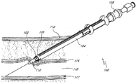
도 1을 참고하면, 혈관 봉합 시스템(100)은 일반적으로 클립(102) 또는 플러그와 같은 혈관 봉합 장치 및 전개 또는 전진 기구(104)를 포함할 수 있다. 플러그 또는 봉합 장치는 또한 밀봉 장치, 임플란트, 혈관 액세스 봉합 장치, 동맥절개부 봉합 장치, 혈관 봉합 장치, 및 조직 봉합 장치를 지칭할 수도 있다. 도시된 바와 같이, 클립(102)은 전개 기구(104)의 원위 단부(105) 상에 로딩된다. 전개 기구(104)는 혈관 도입장치(108) 또는 혈관(18) 내로 삽입된 카테터와 같은 다른 관형 의료 장치에 슬라이딩 방식으로 장착되거나 이를 따라 전진되고 일반적으로 이에 의해 안내된다. 특정 실시예에 있어서, 혈관 도입장치(108)의 삽입을 위해 초기에 형성되는, 피부의 좁은 구멍은 슬라이딩 가능한 안내식 조직 커터(106)에 의해 팽창되거나 확대되어 체내에 대한 전개 기구(104)의 통과를 용이하게 허용하기에 충분히 큰 경피성 구멍(12)을 형성할 수 있다.Referring to FIG. 1, a
전개 기구(104)는, 동맥절개부 위치(14)에 도달할 때까지 경피성 구멍(12)을 통해 혈관 도입장치(108)의 튜브 섹션(110)에 의해 안내될 수 있다. 전개 기구(104)는 동맥절개부(114)를 봉합하기 위해 혈관 봉합 클립(102)을 전개하도록 구성된다. 전개 기구(104)는 이때 후퇴될 수 있다.The
(a) 전개 기구 (a) deployment mechanism
다양한 전개 기구가 본 명세서에 도시 및 설명되어 있다. 당업자라면 개시된 구조에 대한 변형은 본 개시내용의 범위를 벗어나지 않고 행해질 수 있다는 것을 이해할 것이다.Various deployment mechanisms are shown and described herein. It will be understood by those skilled in the art that modifications to the disclosed structure can be made without departing from the scope of the present disclosure.
이제 도 8로 돌아가면, 도 1에서의 전개 기구(104)의 원위 단부(105)에 대한 더욱 상세한 도면이 제시되어 있는데, 이 전개 기구는 클립(102)을 수용하도록 그리고 일반적으로 전개될 때까지 개방 구조로 이 클립을 유지하도록 구성된다. 도시된 실시예에 있어서, 가지(126a, 126b)는 내측 관형 부재(154)의 중심 축선과 실질적으로 평행하며, 가지(126a, 126b)의 원위 단부(127a, 127b)는 내측 관형 부재(154)의 원위 단부(165)와 실질적으로 정렬된다. 다른 실시예에 있어서, 가지(126a, 126b)의 원위 단부(127a, 127b)는 내측 관형 부재(154)의 원위 단부(165)를 약간 넘어 연장될 수 있다. 대안으로, 가지(126a, 127b)의 원위 단부(127a, 127b)가 내측 관형 부재(154)의 원위 단부(165)로부터 근위에서 소정의 간격을 두고 있는 상태에서 전개 기구(104)가 그 초기 구조로 있는 동안 클립(102)은 더욱 근위에 위치하게 될 수 있다. 이하에 더욱 상세하게 설명되는 바와 같이, 클립(102)의 베이스(120)의 내경은 내측 관형 부재(154)의 원위 단부(165)의 외경에 근접하게 위치설정될 수 있거나 또는 상기 외경과 접촉하게 위치설정될 수 있고, 클립(102)의 베이스(120)의 외경은 외측 관형 부재(156)의 원위 단부(173)의 내경에 근접하게 위치설정될 수 있거나 또는 상기 내경과 접촉하게 위치설정될 수 있다. 반경방향 내측을 향해 지향되며 개방 구조에서 가지(126a, 126b)에 의해 작용하는 복원력은, 클립(102)의 내측면과 내측 관형 부재(154)의 외측면 사이의 마찰을 증가시키며, 이로 인해 일반적으로 클립(102)이 내측 관형 부재(154)와 외측 관형 부재(156) 사이의 그 위치로부터 용이하게 멀리 슬라이딩하지 못하도록 한다.Turning now to FIG. 8, a more detailed view of the
외측 관형 부재(156)의 원위 단부(173)는 클립(102)의 베이스(120)를 수용하고 이에 인접하도록 구성되는 내측 레지(ledge) 또는 카운터싱크(countersink; 174)를 포함할 수 있다. 이하에서 더욱 상세하게 설명되는 바와 같이, 조립된 전개 기구(104)가 조직 봉합 위치로 전진되고 내측 관형 부재(154)가 외측 관형 부재(156)로부터 근위 방향으로 축방향으로 후퇴될 때, 원위로 지향되는 반력이 클립(102)의 베이스(120)에 대해 카운터싱크(174)에 의해 가해지며, 이에 따라 클립(102)이 또한 근위 방향으로 이동하는 것을 방지한다. 내측 관형 부재(154)의 원위 단부(165)가 클립(102)의 베이스(120)를 지나 근위 방향으로 이동하게 될 때, 클립(102)과 내측 관형 부재(154) 및 외측 관형 부재(156) 사이의 접촉 관계 또는 인접 관계는 방해를 받고 클립(102)은 전개 기구(104)로부터 릴리스된다. 특정 실시예에 있어서, 카운터싱크(174)를 사용하면 전개 이전에 전진하는 동안 외측 관형 부재(156)가 클립(102)의 전부 또는 일부와 접촉하지 못하도록 허용할 수 있거나 또는 그렇지 않으면 상기 전부 또는 일부를 보호하도록 허용할 수 있다. 다른 실시예에 있어서, 카운터싱크(174)는 생략될 수 있고 외측 관형 부재(156)의 최원위 표면은 베이스(120)에 접촉하도록 구성될 수 있어서 힘을 없애거나 또는 그렇지 않으면 전개 기구(104)로부터 클립(102)의 제거를 허용한다.The
도 9 내지 도 11은 도 7 및 도 8에 도시된 구조가 조립되기 이전에 외측 관형 부재(156)로부터 분리되는 내측 관형 부재(154)의 예를 제시한 것이다. 내측 관형 부재(154)는, 혈관 도입장치(108)와 같은 관형 의료 장치를 수용하도록 구성되는 내측 루멘(166)을 형성한다. 세장형 슬롯(162)은, 전개 기구(104)가 전체적으로 튜브 섹션(110)으로부터 떨어지지 않으면서 의료 전문가에 의해 전개 기구(104)의 적어도 일부가 혈관 도입장치(108)의 근위 부분으로부터 멀리 틸팅되도록 그리고 상기 근위 부분으로부터 축방향으로 분리되도록 허용한다. 예컨대, 도 1을 참고하라. 이러한 구조는, 원하는 조정 또는 진단 과정이 행해지는 동안 의료 전문가가 전개 기구(104)를 경로로부터 벗어나게 위치설정하도록 허용한다. 제시된 실시예에 있어서, 축방향 홈(160)은 내측 관형 부재(154)의 외측면의 길이를 따라 연장되며, 외측 관형 부재(156)의 내측면 상에 형성되는 축방향 돌출부(168)(도 13 참고)와 쌍을 이루도록 구성된다. 이렇게 쌍을 이루는 구조는, 내측 관형 부재(154)가 외측 관형 부재(156)에 대해 회전하는 것을 방지할 수 있고, 내측 관형 부재(154)의 세장형 슬롯(162) 및 외측 관형 부재(156)의 세장형 슬롯(170)을 정렬하는 데 도움이 될 수 있다.Figs. 9-11 illustrate an example of an inner
내측 관형 부재(154)의 근위 단부는, 예컨대, 전개 동안 내측 관형 부재(154)를 후퇴시키도록 하기 위해 의료 전문가에 의해 파지될 수 있는 손잡이(164)를 포함할 수 있다. 상기 손잡이는 일반적으로 사용자에 의해 취급되도록 그리고 사용자가 손잡이에 대한 사용자의 제어에 응답하는 원위 단부의 이동 또는 작동을 달성할 수 있게 하도록 구성된다. 도시된 바와 같이, 손잡이(164)는 일반적으로 이하에서 설명되는 바와 같이 완전한 전개 동안 정지 메커니즘의 래칭 해제(delatching)를 용이하게 하도록 평평한 후위 단부를 갖춘 원형일 수 있다. 다른 형상 및 구조가 또한 사용될 수 있다. 손잡이(164)의 상측 부분은, 세장형 슬롯(162)과 정렬되고 이 세장형 슬롯과 합체되는 절단된 부분(350)을 포함한다. 손잡이(164)의 하위 부분은 외측 관형 부재(156)의 탭(172)을 수용하기 위해 리세스(169)를 포함한다. 손잡이(164)의 원위 단부는, 실질적으로 평평할 수 있는 원위면(354)을 포함한다. 원위면(354)는, 내측 관형 부재(154)가 외측 관형 부재(156) 내로 과도하게 삽입되는 것을 방지하기 위해 외측 관형 부재(156)의 튜브 섹션의 최근위 에지에 이웃하도록 구성된다. 손잡이(164)의 근위면(167)은 실질적으로 평평할 수 있고, 부분 전개 동안 탭(172) 상에서 정지부(175)에 이웃하도록 구성된다. 손잡이(164)의 하위 부분은 각이 진 표면(362)을 포함할 수 있다.The proximal end of the inner
도 12 내지 도 16은 도 7 및 도 8에 도시된 구조가 조립되기 이전에 내측 관형 부재(154)로부터 분리되는 외측 관형 부재(156)의 예를 제시한 것이다. 외측 관형 부재(156)는, 내측 관형 부재(154)를 수용하도록 구성되는 내측 루멘(171)을 형성한다. 세장형 슬롯(170)은 외측 관형 부재(156)의 길이를 따라 연장되며 내측 루멘(171)의 내부에 대한 액세스를 제공한다. 외측 관형 부재(156)의 세장형 슬롯(170)은 내측 관형 부재(154)의 세장형 슬롯(162)과 정렬되도록 구성된다. 외측 관형 부재(156)의 원위 단부는, 전개 기구(104)가 그 초기 구조에 있는 동안 클립(102)에 대한 측부 액세스를 제공하기 위해 하나 이상의 슬롯(176)을 포함할 수 있다.Figs. 12-16 illustrate an example of an outer
탭(172)과 같은 고정 구조 또는 이동 제한 구조가 외측 관형 부재(156)의 근위 단부로부터 연장된다. 탭(172)은 이하에서 더욱 상세하게 설명되는 바와 같이 부분 전개 동안 손잡이(164) 상에서 근위면(167)에 이웃하도록 구성되는 정지면(175)을 포함한다. 탭(172)은 이하에서 추가로 설명되는 바와 같이 전개 기구(104)의 조립을 용이하게 하기 위해 윈도우 부분(177)을 둘러싸는 2개의 테이퍼진 아암(181)을 포함할 수 있다. 탭(172)은 또한 굽힘이 용이하도록 하기 위해 리세스되거나, 약화되거나 또는 힌지된 부분(186)을 포함할 수 있다. 특정 실시예에 있어서, 탭(172)은 약화된 부분(186)을 제외하고 비교적 강성일 수 있다. 특정 실시예에 있어서, 탭(172)의 굽힘은 실질적으로 약화된 부분(186)에서 이루어지도록 구성될 수 있다. 특정 실시예에 있어서, 탭(172)은 비교적 길 수 있다. 예를 들면, 탭(172)은 적어도 약 20 mm일 수 있다. 긴 탭(172)은 의료 전문가에 의한 취급을 용이하게 할 수 있다. 긴 탭(172)은, 굽힘을 발생시키기 위해 의료 전문가에 의해 가해지는 레버리지(leverage)를 또한 증가시킬 수 있다.Such as a
전개 기구는, 일례에서, 가압 요소(158)의 가요성 탭(188) 및 외측 관형 부재(156)의 외측면 상에 형성되는 가압 테이퍼(178)를 포함할 수 있는 감압식 구조를 포함할 수 있다. 외측 관형 부재(156)는 또한 근위에 위치하는 외측면으로부터 연장되는 축방향 돌출부(185)와 같은 감압식 구조를 포함할 수 있다. 다른 구조도 가능하지만, 제시된 바와 같이, 축방향 돌출부(185)는 세장형 슬롯(170)으로부터 실질적으로 정반대의 대향하는 위치에 위치할 수 있다. 램프(ramp) 또는 일방향으로 테이퍼진 잠금부(184)가 축방향 돌출부(185)로부터 연장된다. 일반적으로 환형 형상일 수 있는 정지부(182)가 외측 관형 부재(156)의 외측면으로부터 연장된다. 외측 관형 부재(156)의 외측면은 또한 가압 테이퍼(178)를 포함할 수 있다. 가압 테이퍼(178)는 실질적으로 평평한 표면(180)에서 종료될 수 있다. 표면(180)은 환형 정지부(182)에 이웃할 수 있고 이 환형 정지부와 접촉할 수 있다. 도 16에 도시된 바와 같이, 외측 관형 부재(156)는, 대체로 원형인 외측 관형 부재(156) 상에서 서로로부터 실질적으로 정반대에 대향하는 위치에 위치하는 2개의 가압 테이퍼(178)를 포함할 수 있다. 또한 도시된 바와 같이, 가압 테이퍼(178)는 세장형 슬롯(170) 및 축방향 돌출부(185)로부터 대략적으로 동일한 둘레방향 거리에 위치설정될 수 있다. 다른 구조가 가능하다.The deployment mechanism may include a pressure sensitive structure, which in one example may include a
도 17은 가압 요소(158)의 상세한 도면을 제공하는데, 가압 요소는 일부 실시예에 있어서 외측 관형 부재(156)의 외측면 상에 수용되도록 구성되는 대체로 링 형상인 요소일 수 있다. 특정 실시예에 있어서, 도시된 바와 같이, 가압 요소(158)는 외측 관형 부재(156)와 별도의 요소일 수 있다. 다른 실시예에 있어서, 가압 요소(158)는 외측 관형 부재(156)와 일체로 형성될 수 있다. 이하에서 더욱 상세하게 설명되는 바와 같이, 가압 요소(158)는, 클립(102)의 전개를 안전하게 개시하기 위해 의료 전문가가 대체로 충분하지만 과도하지 않은 압력을 인가하는 것을 보장하는 데 사용될 수 있다. 가압 요소(158)는 내측 관형 부재(154)의 세장형 슬롯(162) 및 외측 관형 부재(156)의 세장형 슬롯(170)과 정렬되는 컷아웃 부분(195)을 포함할 수 있다. 리세스(190)는, 가압 요소(158)가 적절하게 정렬되도록 유지하기 위해 외측 관형 부재(156)의 축방향 돌출부(185)와 쌍을 이루도록 구성될 수 있다. 가압 요소(158)의 내측면은 하나 이상의 가요성 탭(188)을 포함한다. 가요성 탭(188)은, 외측 관형 부재(156)의 가압 테이퍼(178)와 정렬되도록 그리고 이 가압 테이퍼에 걸쳐 전진되도록 구성된다.17 provides a detailed view of the
전개 기구(104)의 조립 동안, 가압 요소(158)는 외측 관형 부재(156)의 근위 단부에 걸쳐 그리고 일방향으로 테이퍼진 잠금부(184)에 걸쳐 전진될 수 있다. 리세스된 부분(190) 및/또는 잠금부(184)는, 이러한 과정이 가능하게 하기 위해 구부러지도록 또는 임시로 충분히 변형되도록 구성될 수 있다. 대안으로, 잠금부(184) 또는 다른 잠금 수단은 가압 요소(158)의 위치설정 이후에 외측 관형 부재(156) 상에 형성될 수 있거나 또는 이 외측 관형 부재에 고정될 수 있다. 테이퍼진 잠금부(184)는, 가압 요소(158)가 외측 관형 부재(156)에 대해 근위 방향으로 너무 멀리 이동하지 않도록 한다. 내측 관형 부재(154)는 이때 외측 관형 부재의 근위 단부로부터 외측 관형 부재(156)의 내측 루멘(171) 내로 삽입될 수 있다. 내측 관형 부재(154)가 외측 관형 부재(156) 내에 삽입될 때, 리세스(169)에 이웃하는 손잡이(164)의 하위 부분의 내측면(183)(도 11 참고)은 탭(172)의 테이퍼진 아암(181)과 접촉하기 시작한다. 내측 관형 부재(154)의 계속된 전진은, 표면(183)이 원위로 아암(181)에 대해 내측으로 지향되는 힘을 인가하도록 한다. 윈도우(177)는, 손잡이(164)가 정지부(175)의 원위로 전진될 때까지 아암(181)이 내측으로 탄성적으로 구부러지도록 해준다. 내측 관형 부재(154)는 이때, 손잡이(354)의 원위면이 외측 관형 부재(156)의 튜브 섹션의 최근위 에지와 접촉할 때까지 추가로 전진될 수 있다.The
봉합 시스템 또는 키트의 일부를 형성하는 전개 기구의 다른 예에 있어서, 혈관 봉합 시스템(600)이 도 64A 내지 도 64E에 도시되어 있다. 혈관 봉합 시스템(600)은, 서로 연통되는 3개의 부분, 즉 플런저(610), 캡슐(630) 및 도입장치(650)를 더 제공하기에 적합하도록 구성된다. 플런저(610)는 전개 플런저(612) 그리고 가이드 및 시일 조립체(614)를 더 포함한다. 전개 플런저(612)는, 가이드 및 시일 조립체(614)에 형성된 개구 내에 수용되도록 구성되는, 원통형 로드 또는 실질적으로 원통형인 로드와 같은 로드이다. 플런저(612)는, 중앙 축선(A)을 따라 적어도 하나의 방향으로 이동 가능하도록 구성된다. 플런저는, 일부 구성에서는, 제거 가능할 수 있는 플런저 선단부(620)에서 종료될 수 있다.In another example of a deployment device that forms a seal system or portion of a kit, a
봉합 장치 캡슐(630)은 근위 단부(70)에서 플런저와, 그리고 원위 단부(80)에서 도입장치와 결합된다. 봉합 장치 캡슐(630)은 전개 카트리지 본체(632) 및 압축성 섹션(634)을 포함한다. 일부 구성에 있어서, 봉합 장치 캡슐(630)은 도입장치 캡의 적어도 일부 내에 스냅식으로 끼워지기에 적합하도록 구성된다.The
도입장치(650)는 캡슐(630)의 일부를 수용하기에 적합하도록 되어 있다. 캡슐(630)의 오목한 노우즈(646)는 전개 동안 봉합 장치(670)의 코킹(cocking)을 최소화하기 위해 도입장치 보어의 개구 내에 정렬되도록 위치설정된다. 중앙 개구(656)가 마련되며 이 중앙 개구를 통해 캡슐(630) 내에 수용되는 클립, 플러그 또는 봉합 장치(670)가 전개 동안 진행할 수 있다. 이러한 구성에서는, 이송 동안 캡슐 내에서 적소에 봉합 장치(670)을 유지하는 지혈 밸브(652)가 도입장치 상에 마련된다.The
일단 도입장치, 캡슐(630) 및 플런저가 조립되면, 구성요소들은 사용 중에 분리되지 않는다. 이러한 특징은, 일단 클립, 플러그 또는 봉합 장치(670)가 혈관 내에서 전개되면 의도하지 않은 조립 해제를 방지한다. 예를 들면, 전체 전개 조립체 및 도입장치가 단일 유닛으로서 후퇴되지 않는다면, 클립, 플러그 또는 봉합 장치(670)는 플런저에서 벗겨지게 된다. 이는 동맥절개부 위치에서 적절하게 안착하지 못하고 클립, 플러그 또는 봉합 장치(670)가 혈관에 전개되는 결과를 초래할 수 있다. 도 64C에 도시된 바와 같이, 캡슐(630)은 그 근위 단부에서 도입장치(650)에 걸쳐 스냅식으로 끼워지고 캡슐(630)은 그 근위 단부에서 도입장치 내에 스냅식으로 끼워진다. 플런저(610)가 캡슐(630) 상에 완전하게 위치설정될 때 캡슐(630)의 외측면(631) 상에 마련되는 멈춤쇠(636) 내에 끼워지는 플런저(610)로부터 연장되는 아암 또는 캡(616)의 원위 단부(80) 상에 추가적인 플랜지(675)가 마련될 수 있다.Once the introducer, the
각각의 구성요소는 도 64E 내지 도 64H에 더욱 상세하게 도시된 바와 같이 일방향 스냅 특징부를 제공하도록 구성될 수 있다. 도 64E 및 도 64F에서, 플런저 그립(610)은 캡슐(630) 상에 스냅 결합되어 있고 시스템에는 도시된 내부 잠금용 특징부가 마련되는데, 도입장치(650)의 근위 단부(70)가 축선(A)으로부터 반경방향으로 연장되는 아암 또는 캡(656)을 구비하고 다음으로 축선(A)에 대해 평행한 축선을 따라 또는 축선(A)에 실질적으로 평행한 축선을 따라 구부러지게 연장되어 캡슐(630)의 원위 단부(80)의 외측면과 결합되어 쌍을 이루는 것을 특징으로 한다. 캡슐(630)은 그 원위 단부(80)에서, 도입장치의 내측 리세스 내에 끼워지도록 구성되는 언더컷이 추가로 마련될 수 있는 테이퍼진 선단부(636)를 특징으로 한다.Each component can be configured to provide a one-way snap feature as shown in more detail in Figures 64E-64H. 64E and 64F, the
외부 잠금용 특징부의 예는 도 64G 및 도 64H에 더욱 상세하게 도시되어 있다. 이전의 도시내용과 관련하여, 플런저 그립(610)은 캡슐(630) 상에 스냅 결합되어 있다. 외부 잠금용 특징부가 마련되는 위치에서, 도입장치(650)의 근위 단부는, 캡슐(630)의 외측면(631) 상에 형성되는 홈(642) 내에 끼워지는 핑거(660)를 더 포함하고 캡슐(630)이 내부에 끼워지는 플랜지를 구비한다.Examples of features for external locking are shown in more detail in Figures 64G and 64H. In connection with the prior art contents, the
이하에서 더욱 상세하게 설명되는 조직 클립 및 플러그는, 예컨대 도 65A 내지 도 65G에 도시된 바와 같이 캡슐(630) 내에 클립, 플러그 또는 봉합 장치(670)를 마련함으로써 시스템을 이용하여 전개될 수 있다. 캡슐(630)은, 근위 단부(70)에서 제1 직경을 갖고 원위 단부(80)에서 이보다 작은 직경을 갖는 관형 외측면(631)을 갖는다. 당업자가 이해할 수 있는 바와 같이, 관형 캡슐은 원형, 계란형, 다각형, D자 형상 등을 포함하는 다양한 단면 구조를 취할 수 있다. 예시를 목적으로, 관련되는 크기 및 체적에 대한 콘텍스트(context)를 제공하기 위해 원형 단면 형상에 대해 치수가 제시되어 있다. 추가적으로, 이러한 크기는 사용되는 도입장치의 크기에 따라 변경될 수 있다. 당업자라면, 도입장치는 8 French 내지 20 French(그리고 이 범위 내의 값)에서 변할 수 있다는 것을 이해할 것이다. 따라서, 치수는 도입장치의 French 치수에 비례하게 될 것이다. 따라서, 예를 들면, 제1 직경의 통상의 직경은, 약 4 mm 내지 25 mm일 수 있으며, 더욱 바람직하게는 약 8 mm일 수 있고, 또는 이 범위 내의 임의의 값에서 약 1/100 mm의 공차를 갖는다. 제2 직경의 통상의 직경의 범위는, 약 1 mm 내지 약 3 mm이며, 더욱 바람직하게는 약 2 mm이고, 또는 이 범위 내의 임의의 값에서 약 1/100 mm의 공차를 갖는다. 캡슐의 전체 길이 범위는, 약 12 mm 내지 약 50 mm이거나, 또는 최대 100 mm이며, 더욱 바람직하게는 약 35 mm일 수 있고, 또는 이 범위 내의 임의의 값에서 약 1/100 mm의 공차를 갖는다. 캡슐(630)은 대략적으로 중간 길이에 투명한 관형 섹션(640)을 포함하는데, 클립, 플러그 또는 봉합 장치의 존재는 이를 통해 관찰될 수 있고, 캡슐(630) 내에 수용되는 클립, 플러그 또는 봉합 장치(670)가 전개될 때 이를 통해 유체 유동을 관찰할 수 있다. 길이방향 축선(A)을 따르는 단면으로 도시된 바와 같이, 캡슐 본체(632)는 근위 단부(70), 원위 단부(80) 및 중간 섹션을 포함한다. 개구(638, 638')는 근위 본체 섹션 및 원위 본체 섹션 양자 모두에 마련된다. 도시된 바와 같이 밸브(648)가 마련될 수 있다. 봉합 장치(670)는, 사용자가 캡슐 본체(632) 내부에서 클립, 플러그 또는 봉합 장치(670)를 볼 수 있도록, 캡슐 본체(632)가 구성되는 위치에서 캡슐(630)의 내부 내에 위치설정된다. 플런저 그립(610)의 오목한 노우즈(646)는 캡슐(630) 상에 스냅 결합되고 시스템에는 도시된 내부 잠금용 특징부가 마련되는데, 도입장치(650)의 근위 단부(70)는, 그 직경이 그 근위 단부(70) 및 그 원위 단부(80)에서 실질적으로 동일하게 되지 않도록 그 길이를 따라 테이퍼질 수 있는 것을 특징으로 한다. 추가적으로, 노우즈(646) 내부의 세장형 개구(638')는 또한 그 길이를 따라 직경 면에서 변할 수 있다. 원위 단부에서의 테이퍼진 단부 선단부(646)는, 밸브가 적어도 일시적으로 개방될 수 있도록 하기 위해 도입장치(650) 내에서 지혈 밸브(652)를 팽창시키도록 구성되며, 이에 따라 플런저(612)의 원위 단부로부터 클립, 플러그, 혹은 봉합 장치를 제거하지 않고 또는 클립, 플러그 혹은 봉합 장치(670)를 잠재적으로 손상시키지 않고 밸브를 통해 클립, 플러그 또는 봉합 장치(670)가 전진될 수 있도록 해준다. 전개 동안 진행하는 클립, 플러그 또는 봉합 장치(670)가 통과하는 노우즈(654) 내에서 세장형 개구의 단면을 변경함으로써, 클립, 플러그 또는 봉합 장치(670)가 전방을 향해 전진될 때 클립, 플러그 또는 봉합 장치(670)는 이에 따라 감소된 프로파일을 달성하도록 조작될 수 있다. 시스루 챔버(see-through chamber)는 혈액과 같은 유체가 유동하도록 해주며, 이에 따라 도입장치 시스의 적절한 위치가 달성되는 것을 확인하게 해준다. 캡슐(630)은 또한, 클립, 플러그 또는 봉합 장치(670)와 접촉하고 이를 전진시키기 위해 툴의 삽입을 위한 가이드를 포함하도록 구성될 수 있다. 여기서 도시된 구조에 있어서, 클립, 플러그 또는 봉합 장치(670)의 레그는 원위 단부 섹션 상에서 보어의 에지에 안착하도록 위치설정된다.The tissue clips and plugs described in more detail below can be deployed using the system by providing clips, plugs or sealing
이제 도 66A 내지 도 66D로 돌아가면, 조립 해제를 제공하도록 구성되는 캡슐(630) 및 플런저 조립체의 추가적인 구조가 제시된다. 제시된 구조는, 일단 클립, 플러그 또는 봉합 장치가 혈관 내로 완전히 연장되면 도입장치로부터 전개 조립체의 의도치 않은 분리를 방지하기에 적합하도록 구성된다. 일부 구조는, 필요하다면 내과의사에 의한 의도적인 무시를 가능하게 하기에 적합하도록 구성될 수 있다. 이전의 구조와 관련하여, 혈관 봉합 시스템(600)은, 서로 연통되는 3개의 부분, 즉 플런저(610), 캡슐(630) 및 도입장치(650)를 더 제공하기에 적합하도록 구성된다. 플런저(610)는 전개 플런저(612) 그리고 가이드 및 시일 조립체(614)를 더 포함한다. 전개 플런저(612)는, 가이드 및 시일 조립체(614)에 형성된 개구 내에 수용되도록 구성되는, 원통형 로드 또는 실질적으로 원통형인 로드와 같은 로드이다. 플런저(612)는, 중앙 축선(A)을 따라 제1 방향 및 제2 방향으로 이동 가능하도록 구성된다. 플런저(610)는 캡슐(630)의 근위 단부(70)에 걸쳐 끼워지며 이 근위 단부 상에 스냅 결합된다. 대안으로, 내부 잠금용 특징부가 마련될 수 있는데, 이때 플런저(610)의 수형 섹션은 캡슐(630)의 근위 단부에 있는 쌍을 이루는 암형 리세스 내로 슬라이딩하고 도 66D에 도시된 바와 같이 적소에 잠기게 된다. 일부 구조에서는, 별도의 시일이 마련되지 않는다. 오히려, 봉합 장치가 캡슐 내에서 밀폐시킬 때 봉합 장치 자체에 의해 지혈이 달성된다. 따라서, 이들 구조 중 임의의 구조에서 별도의 시일을 마련하는 것은 선택적이다.Turning now to Figures 66A-66D, additional structures of the
전개 시스템의 추가적인 양태는, 코디스(Cordis)로부터 입수 가능한 도입장치 시스템(도 67 및 도 69) 및 세인트 주드 메디컬(St. Jude Medical)로부터 입수 가능한 도입장치 시스템(도 68)과 같이 상업적으로 입수 가능한 다양한 도입장치 시스템과 함께 이용될 수 있는 것이다. 도 67A 내지 도 67E, 도 68A 및 도 68B 그리고 도 69A 및 도 69B에 도시된 바와 같이, 각각의 시스템(600)은, 플런저(610), 플런저(610)와 조합되는 이송 캡슐(630), 플런저 튜브(618), 콜릿 카트리지 인서트(623), 이송 캡 콜릿(621), 생흡수성 봉합 장치(670), 테더(662), 테더 견인 요소(664)를 포함한다. 도 68 및 도 69에 도시된 바와 같이 플런저 선단부(613)가 또한 마련될 수 있다. 본 명세서에 도시되는 도입장치는 보통 길이에 있어서 약 120 mm 내지 약 170 mm의 범위이거나, 또는 이 범위 내의 임의의 값에서 약 1/100 mm의 공차를 갖는다. 플런저 튜브는 보통, 상업적으로 입수 가능한 도입장치의 길이보다 15 mm 내지 50 mm 더 길고, 이를 위해 예컨대 120 mm 도입장치와 함께 작동하도록 구성되는 전개 시스템과 쌍을 이루도록 구성되면, 길이에 있어서 약 135 mm 내지 약 170 mm 또는 이 범위 내의 임의의 길이인 플런저를 구비하며, (6 French의 도입장치에 대해) 약 1.0 mm 내지 약 2.4 mm의 내경을 갖는다. 상기 시스템은, 폐색 또는 다른 이유 때문에 더 이상 사용할 수 없게 되는 투석 혈관 액세스 위치(예컨대, 관상기관 및/또는 이식편을 포함함)의 간단하고 용이한 비수술 봉합을 가능하게 하도록 구성될 수 있다.Additional aspects of the deployment system are described in more detail in commonly assigned US Pat. Nos. 5,104,302, 5,602,658, 5,602,657, 6,104,657, It can be used with various introduction apparatus systems. As shown in Figures 67A-67E, 68A-68B and 69A-69B, each
이송 캡슐(630)에 대한 적절한 구조는 도 70A 내지 도 70F에 더욱 상세하게 도시되어 있다. 이송 캡슐(630)은, 그 원위 단부(80)에서 약 4mm 내지 12 mm의 외경을 갖고 그 근위 단부에서 약 3 mm 내지 약 11 mm의 외경을 갖거나, 또는 이 범위 내의 임의의 값에서 약 1/100 mm의 공차를 갖는다. 장치가 대량으로 제조되는 경우, 원위 선단부 및 캡슐은 단일 구성요소로서 구성될 수 있다. 근위 단부(70)는, 내부로 가이드 조립체가 끼워지는 개구를 가지며(앞서 도 64에 도시된 바와 같음), 이송 위치로 봉합 장치를 밀어낼 때 진행할 수 있는 전개 플런저가 통과하는 개구를 갖는다. 원위 단부(80)는 [벽에 도달할 때까지 캡슐(630)의 외측면(631) 둘레에 끼워지는] 도입장치와의 결합을 용이하게 하기 위해 더 작은 외경을 갖는다. 원위 단부(80)로부터 캡슐(630)의 배럴을 아래에서 본 도면인 도 70C로부터, 중앙 개구(644)를 볼 수 있고 카운터보어(counterbore)로부터 형성되는 저부면(649)은 측벽 및 베이스 표면을 특징으로 한다. 도 70D 및 도 70E에 도시된 이송 캡슐 콜릿(621)은, 약 3 mm 내지 약 4 mm 범위의 제1 직경을 갖거나, 또는 이 범위 내의 임의의 값에서 약 1/100 mm의 공차를 갖는 직경을 갖는 제1 직경을 갖거나, 약 2.7 mm 내지 약 3.0 mm 범위의 제2 직경을 갖거나, 또는 이 범위 내의 임의의 값에서 약 1/100 mm의 공차를 갖는 제2 직경을 갖는다. 개구의 내경은, 그 근위 단부에서 약 1.5 mm 내지 약 1.9 mm 범위이며 그 원위 단부에서 약 1.3 mm 내지 약 1.7 mm 범위이거나, 또는 이 범위 내의 임의의 값에서 약 1/100 mm의 공차를 갖는다. 도 70F로부터, 근위 단부(더 넓음)로부터 원위 단부(더 좁음)까지 콜릿(621)의 외측면의 외부 테이퍼는, 약 0.4 ° 내지 약 8 °, 더욱 바람직하게는 약 5 °의 값을 갖거나, 이 범위 내의 임의의 값을 갖는다.Suitable structures for the
콜릿 카트리지 인서트(623)가 도 71A 내지 도 71C에 도시되어 있다. 콜릿 카트리지 인서트는, 캡슐을 유지하기 위해 이송 캡슐의 테이퍼진 내부 내로 삽입되는 슬롯 형성된 원통형 클램프이다. 콜릿 카트리지 인서트는 축선(A)을 따라 관통하는 개구를 갖춘 원통형 프로파일을 갖는다. 이 개구는 도 71B에 제시된 바와 같이 테이퍼진 치수를 갖는다. 도 71C는 콜릿 카트리지 인서트의 원위 단부(80)로부터의 단부도이다. 콜릿은 보통 근위 단부(70)에서 제1 외경을 갖고 원위 단부(80)에서 제2 외경을 갖는다. 상기 제1 외경은, 약 4.4 mm 내지 약 5.0 mm 범위이거나, 또는 이 범위 내의 임의의 값에서 약 1/100 mm의 공차를 갖고, 상기 제2 외경은, 약 4.7 mm 내지 약 5.0 mm 범위이거나, 또는 이 범위 내의 임의의 값에서 약 1/100 mm의 공차를 갖는다. 개구의 내경은, 그 근위 단부에서 약 3.3 mm 내지 약 3.9 mm 범위이며 그 원위 단부에서 약 1.5 mm 내지 약 1.8 mm 범위이거나, 또는 이 범위 내의 임의의 값에서 약 1/100 mm의 공차를 갖는다. 근위 단부(더 넓음)로부터 원위 단부(더 좁음)까지 콜릿 카트리지 인서트의 내부 개구의 외부 테이퍼는, 약 0.4 ° 내지 약 8 °, 더욱 바람직하게는 약 5 °의 값을 갖거나, 이 범위 내의 임의의 값을 갖는다.
이송 캡슐(630) 원위 선단부(654)는 도 72A 내지 도 72E에 더욱 상세하게 도시되어 있다. 이송 캡슐(630) 원위 선단부(654)는 이를 관통하는 개구(636)를 갖춘 스템을 갖는다. 스템은 또한 본 개시내용의 범위로부터 벗어나지 않고 코어, 컬럼, 수직 섹션, 중간 섹션, 센터, 포스트 또는 샤프트로서 불리워질 수 있다. 개구는 직경 면에서 그 근위 단부에서 약 3.8 mm 내지 약 4.2 mm, 더욱 바람직하게는 약 4.02 mm, 또는 이 범위 내의 임의의 값에서 약 1/100 mm의 공차를 가지며, 다음으로 그 테이퍼진 선단부(638)를 따라 약 2.4 mm 내지 약 2.6 mm, 또는 더욱 바람직하게는 약 2.51 mm이거나 이 범위 내의 임의의 값에서 1/100 mm의 공차를 갖는 직경으로 아래로 테이퍼진다. 원위 선단부의 길이는, 약 4.0 mm 내지 약 25.0 mm의 범위이며, 더욱 바람직하게는 약 18 mm이거나, 또는 이 범위 내의 임의의 값에서 약 1/100 mm의 공차를 갖는다. 일부 구조에 있어서는, 35 mm보다 큰 길이가 적절할 수 있다. 이송 캡슐 원위 선단부의 외경은 약 3.0 mm 내지 약 4.0 mm, 더욱 바람직하게는 3.2 mm이거나, 또는 이 범위 내의 임의의 값에서 약 1/100 mm의 공차를 갖는다. 외경은 일부 경우에 있어서 최대 35 mm 이상일 수도 있다. 가장 넓은 섹션의 외경은, 약 4.5 mm 내지 약 10.0 mm의 범위이며, 더욱 바람직하게는 약 5.7 mm이거나, 또는 이 범위 내의 임의의 값에서 약 1/100 mm의 공차를 갖는다. 일부 구조에 있어서, 가장 넓은 섹션은 최대 35 mm 또는 이보다 더 클 수 있다. 근위 섹션의 외경은, 약 4.5 mm 내지 약 10.0 mm의 범위, 더욱 바람직하게는 약 5.7 mm이거나, 또는 이 범위 내의 임의의 값에서 약 1/100 mm의 공차를 갖는다. 내부의 테이퍼진 섹션(634)은 근위 단부(70) 근처에 위치하게 된다. 원위 선단부는 넥(neck)의 반경보다 더 큰 반경을 갖는 중간 본체를 갖는다. 원위 선단부보다 크지만 중간 본체보다는 작은 반경을 갖는 근위 섹션이 마련된다. 이송 캡슐(630)의 투명한 근위 모듈 섹션은 도 73A 내지 도 73E에 더욱 상세하게 도시되어 있다. 이 투명한 섹션은 관통하는 개구(637)를 갖춘 본체를 갖는다. 상기 본체는, 그 근위 단부(70)에서 플런저의 원위 단부(80)와 결합하게 크기가 결정되는 외경을 제공하도록 그리고 그 원위 단부(80)에서 이송 메커니즘의 근위 단부(70)와 결합하게 크기가 결정되는 외경을 제공하도록 구성된다. 제시된 바와 같이, 근위 단부(70)의 외경은 중간 섹션의 직경보다 크지만, 원위 섹션의 직경보다는 작다. 원위 단부(80)에서의 개구는 충분히 커서, 이송 메커니즘의 근위 단부(70)가 원위로 향하는 표면에 대해 이웃하고 리세스 내에 끼워질 수 있도록 한다. 개구의 근위 단부(70)는, 모듈의 근위 단부(70)에 도달할 때 플레어(flare)되는 직경을 갖는다.The
캡슐은 밀봉 요소 또는 혈관 봉합 장치를 수용하며, 전개 프로세스 동안 손상으로부터 장치를 보호한다. 캡슐의 구조에 따른 결과로서, 캡슐은 또한, 도입장치에 진입하는 혈관 봉합 장치에 앞서 혈관 봉합 장치의 단면 직경의 축소를 개시한다. 캡슐은, 예컨대 혈관 봉합 장치의 반경방향 연장 섹션을 편향시킴으로써 혈관 봉합 장치의 단면 직경의 감소를 달성한다. 캡슐은 또한, 캡슐 내에서 볼 수 있는 혈액의 존재에 의해 목표 혈관 내에 도입장치 시스가 위치설정되어 있음을 확인하는 것을 용이하게 한다.The capsule accommodates a sealing element or vascular closure device and protects the device from damage during the deployment process. As a result of the structure of the capsule, the capsule also begins to reduce the cross-sectional diameter of the vascular closure device prior to the vascular closure device entering the introduction device. The capsule achieves a reduction in the cross-sectional diameter of the vascular closure device, for example, by deflecting a radially extending section of the vascular closure device. The capsule also facilitates confirming that the introduction device sheath is positioned within the target vessel by the presence of blood visible within the capsule.
플런저 그립(610)이 도 74A 내지 도 74D에 도시되어 있다. 플런저 그립(610)은 사용자에 의한 결합을 용이하게 하는 가변적인 외측면을 제공하도록 구성된다. 근위 단부(70)는, 그 원위 단부(80)에서 넓어지기 이전에 더 좁은 넥 내로 테이퍼지는 노브(knob)형 형상을 갖는다. 축선(A)을 따라 그 길이의 일부를 통해 중앙 루멘(622)이 마련되는데, 근위 단부(70) 이전에 종료된다. 수직 개구는, 중앙 루멘과 연통하는 원위 단부(80) 근처에 마련될 수 있다. 수직 개구는, 예를 들어, 플런저의 전체 길이의 조정을 허용하기 위해 세트 스크류와 함께 사용하기 위한 나사식 구멍일 수 있다. 플런저 그립의 길이는, 약 12 mm 내지 약 45 mm이거나, 더욱 바람직하게는 25 mm이고, 또는 이 범위 내의 임의의 값에서 약 1/100 mm의 공차를 갖는다. 플런저 그립의 외경은, 그 길이를 따라 약 3.0 mm 내지 약 12 mm 범위이며, 더욱 바람직하게는 그 가장 넓은 섹션에서 약 10 mm이고 그 가장 좁은 섹션에서 약 6 mm이고, 또는 이 범위 내의 임의의 값에서 약 1/100 mm의 공차를 갖는다. 플런저의 오목한 중앙 부분은 특히, 그 길이를 따라 길이의 약 5 mm 내지 길이의 약 20 mm 범위, 더욱 바람직하게는 7 mm 내지 약 15 mm 범위의 가변적인 외경을 갖고, 또는 이 범위 내의 임의의 값에서 약 1/100 mm의 공차를 갖는다. 이러한 특징은 선택적이지만, 이는 근위 단부에서의 내과의사의 파지를 개선한다. 중앙 루멘은 플런저 로드 또는 튜브와의 결합을 위한 것이다.
플런저 그립의 변형례가 도 75A 내지 도 75C에 도시되어 있다. 도시된 바와 같이, 플런저 그립(610)은 그 길이를 따라 오목한 섹션을 갖지 않는다. 플런저 그립은, 제1 내경 및 제2 내경을 갖는 중앙 루멘(622)을 구비하며, 그 길이는 약 10 mm 내지 약 35 mm, 더욱 바람직하게는 약 16 mm이고, 또는 이 범위 내의 임의의 값에서 약 1/100 mm의 공차를 갖는다. 루멘의 제1 내경은, 약 6.3 mm 내지 약 7.7 mm 범위이거나, 더욱 바람직하게는 약 7 mm인 반면, 플런저 그립의 외경은 약 7.6 mm 내지 약 8.9 mm의 범위이거나, 더욱 바람직하게는 약 8 mm이고, 또는 이 범위 내의 임의의 값에서 약 1/100 mm의 공차를 갖는다. 제2 내경은, 약 1.2 mm 내지 약 1.8 mm이거나, 더욱 바람직하게는 1.6 mm이고, 또는 이 범위 내의 임의의 값에서 약 1/100 mm의 공차를 갖는다. 제1 내경 섹션의 루멘의 길이는, 약 5.0 mm 내지 약 7.6 mm 범위이고, 더욱 바람직하게는 약 6.4 mm이고, 또는 이 범위 내의 임의의 값에서 약 1/100 mm의 공차를 갖는 반면, 제2 내경 섹션의 루멘의 길이는 약 7.6 mm 내지 약 11.4 mm 범위이며, 더욱 바람직하게는 약 9.4 mm이고, 또는 이 범위 내의 임의의 값에서 약 1/100 mm의 공차를 갖는다.A modification of the plunger grip is shown in Figures 75A-75C. As shown, the
시스템의 일부 구조에 있어서, 테더 라인(672)이 채용될 수 있다. 테더는 또한 본 개시내용의 범위로부터 벗어나지 않고 리쉬(leash), 임시의 또는 제거 가능한 플러그 부착 메커니즘, 봉합선, 나사산, 와이어, 라인, 수용 부재, 수용 요소, 안정 요소 및 포획 요소라고 불릴 수 있다. 테더는 생흡수성, 생분해성일 수 있거나, 다른 방식으로 체내에서 분해될 수 있다. 적절한 테더 라인 구조가 도 76A 및 도 76B 그리고 도 77A 및 도 77B에 도시되어 있다. 테더 라인(672)은 도 76A에 도시된 바와 같이 연속적인 루프일 수도 있고 도 81A 내지 도 81D에 도시된 바와 같이 테더(674)를 형성하는 와이어일 수도 있다. 도 68 및 도 69에 도시된 바와 같은 일부 구조에서, 플런저 선단부(662)는 테더 라인 없이 채용된다. 플런저 선단부의 적절한 구조가 도 78A 내지 도 78E에 도시되어 있다. 플런저 선단부(662)는 혈관 봉합부의 근위 단부에서 도 79E에 도시된 바와 같이 적절히 쌍을 이루는 리세스(676) 내에 스냅식으로 끼워지도록 되어 있는 테이퍼진 근위 단부(70) 및 둥근 원위 선단부(80)를 갖는다. 도 68, 도 69 및 도 78E는 플런저 스템에서의 플런저 선단부를 도시한 것이다. 플런저 선단부의 전체 길이는, 예컨대 약 7.6 mm 내지 약 11.4 mm이거나, 더욱 바람직하게는 약 9.5 mm일 수 있고, 또는 이 범위 내의 임의의 길이에서 약 1/100 mm의 공차를 갖는다. 근위 단부는, 약 1.02 mm 내지 약 1.27 mm, 더욱 바람직하게는 약 1.14 mm인 제1 직경, 또는 이 범위 내의 임의의 직경에서 약 1/100 mm의 공차를 갖는 것인 사다리꼴 단면(664)을 갖는다. 약 0.76 mm 내지 약 1.02 mm 범위, 더욱 바람직하게는 약 0.89 mm인 길이에 걸쳐, 상기 사다리꼴 단면은 약 1.02 mm 내지 약 1.27 mm, 더욱 바람직하게는 1.14 mm, 또는 이 범위 내의 임의의 직경에서 약 1/100 mm의 공차를 갖는 것인 직경으로 넓어진다. 사다리꼴 섹션의 근위 단부와 유사한 직경 그리고 약 0.76 mm 내지 약 1.02 mm, 더욱 바람직하게는 약 0.89 mm의 길이를 갖는 것인 좁아지는 중간 넥 섹션(666)이 후속한다. 플런저 선단부의 메인 본체(668)의 직경은, 약 1.77 mm 내지 약 2.29 mm이거나, 더욱 바람직하게는 약 1.98 mm이고, 또는 이 범위 내의 임의의 직경에서 약 1/100 mm의 공차를 갖는다. 도 78C에 도시된 근위 단부로부터 플러그에서 본 도면을 참고하면, 사다리꼴 단면의 근위 단부의 3가지 가변적인 직경, 사다리꼴 섹션의 더 넓은 직경 및 메인 본체를 볼 수 있다. 좁아지는 중간 넥의 직경은 볼 수 없다. 메인 본체(668) 이후에, 스템 섹션(665)은 근위 단부로부터 원위 단부를 향해 약 3.05 mm 내지 약 4.32 mm, 더욱 바람직하게는 약 4.04 mm이고, 또는 이 범위 내의 임의의 값에서 약 1/100 mm의 공차를 갖는 길이에 걸쳐 좁아진다. 스템 섹션(665)은 구근형 단부(667)의 형성과 함께 원위에서 종료된다. 구근형 단부의 직경은, 약 1.02 mm 내지 약 1.17 mm이거나, 더욱 바람직하게는 약 1.14 mm이고, 또는 이 범위 내의 임의의 값에서 약 1/100 mm의 공차를 갖는다. 도 78D에 도시된, 원위 단부로부터 본 바와 같이, 구근형 단부의 직경을 볼 수 있으며, 메인 본체를 볼 수 있다. 도 78E를 다시 살펴보면 이해할 수 있는 바와 같이, 플런저는 플런저 스템(618)의 원위 단부에서 개구 내에 끼워지며, 이는 그 근위 단부에서 손잡이에 연결된다.In some structures of the system, a
(b) 조직 클립, 플러그 및 다른 봉합 장치 (b) tissue clips, plugs and other sealing devices
본 명세서에서 개시되는 조직 클립, 플러그 및 다른 봉합 장치는, 예컨대 동맥을 봉합하려는 목적으로 동물 신체 내로 이송하는 상황에 대해서 개시된다. 그러나, 당업자가 이해할 수 있는 바와 같이, 다른 용례가 가능하다. 예를 들면, 클립, 플러그 및 다른 봉합 장치는, 지혈하기 위한 압박의 대안으로서, 이송 시스템에 의한 이송을 필요로 하지 않고 오히려 외상 - 자상 또는 총상과 같은 외상 - 의 상황에서 필드에서 이송되도록 치수가 결정될 수 있다. 한정하는 것은 아니지만, 에지, 릿지, 플랜지, 윙, 페달, 반경방향 연장 부재, 및 수평 돌출부를 포함하는 외측면 또는 내측면 상에서 봉합 장치와 함께 다양한 요소가 이용될 수 있다. 임의의 이러한 요소에 대한 모든 논의는 또한 개시되는 다른 요소를 참고할 수 있다.The tissue clips, plugs, and other sealing devices disclosed herein are disclosed for situations in which an artery is delivered into an animal body for the purpose of sealing the artery. However, as will be understood by those skilled in the art, other applications are possible. For example, clips, plugs, and other sealing devices may be used as an alternative to compression for hemostasis, without the need for transfer by a transfer system, but rather for the purpose of transferring from the field in a traumatic situation such as a trauma- Can be determined. A variety of elements can be used with the sealing device on the outer or inner side including, but not limited to, edges, ridges, flanges, wings, pedals, radially extending members, and horizontal protrusions. Any discussion of any such element may also refer to other elements disclosed herein.
도 2는 개방 또는 예비 전개된 구조인 클립(102)의 실시예의 사시도를 도시한 것이다. 클립(102)은 베이스 부분(120)을 포함할 수 있다. 베이스 부분(120)은 대체로 또는 완전하게 환형일 수 있으며, 이에 따라 부분적이거나 완전한 원을 형성한다. 일부 실시예에 있어서, 도시된 바와 같이 그 상부 에지를 따라 연속적이거나 실질적으로 연속적인 원형인 베이스 부분(120)은 개방 구조 및 폐쇄 구조 중 어느 하나 혹은 양자 모두에서 뒤틀림 또는 굽힘에 대해 큰 강도 및 저항을 제공할 수 있다. 대체로 원형인 베이스 부분(120)은, 가지(126a, 126b)가 천이 동안 개방 구조와 폐쇄 구조 사이에서 이동하거나 구부러지도록 해주는 반면, 베이스 부분(120)의 형상 또는 배향에서 실질적인 변화에 저항한다. 베이스 부분(120)의 높이(135)는 원하는 정도의 강성 또는 가요성을 달성하도록 선택될 수 있다.Figure 2 shows a perspective view of an embodiment of
핑거(122 및 124)는, 가지(126a, 126b)와 같은 복수 개의 조직 결합 요소를 지지하도록 그리고 베이스 부분(120)으로부터 연장되도록 구성 가능할 수 있다. 일부 실시예에 있어서, 도시된 바와 같이, 핑거(122) 및 핑거(124)는 예컨대 실질적으로 대향하는 배치로 위치설정될 수 있는데, 핑거(122)는 핑거(124)로부터 대체로 원형인 베이스 부분(120) 상에서 실질적으로 정반대에 대향하는 위치에 위치설정된다. 이하에서 설명되는 바와 같이, 다수의 다른 위치 및 구조를 이용할 수 있다.
도 2에 제시된 예에 있어서, 각각의 핑거(122, 124)는 3개의 가지, 즉 하나의 중앙 가지(126a) 및 2개의 외측 가지(126b)를 포함한다. 외측 가지(126b)는 각각의 선단부(127b)로부터 각각의 핑거(122, 124)의 전방 표면(134)를 갖춘 각각의 접합부까지 실질적으로 동일한 길이일 수 있다. 일부 실시예에 있어서, 상기 전방 표면(134)은 개방 구조에서 가지(126a, 126b)에 실질적으로 수직일 수 있고, 베이스 부분(120)의 평면과 실질적으로 평행일 수 있다. 일반적으로 표면(134)은 혈관 벽(16) 내로의 클립(102)의 과도한 삽입을 방지하고자 실질적으로 뭉툭한 정지부로서 작용할 수 있다. 일부 실시예에 있어서, 중앙 가지(126a)의 길이(133)는 외측 가지(126b)의 길이(132)보다 약간 클 수 있다. 이러한 길이차는, 조직 틈새의 대체로 대향하는 측부들을 함께 잡아당기기에 도움이 되도록 2개의 대향하는 중앙 가지(126a) 사이에서 베이스 부분(120)을 대체로 양분하는 중앙선을 따라 레버리지 및 힘을 증가시키는 것을 보조할 수 있다.In the example shown in FIG. 2, each
일부 실시예에 있어서, 길이(132, 133)는, 가지(126a, 126b)가 혈관(18)의 내부 영역 내로 평균 두께의 혈관 벽(16)을 통해 침투하지만 완전히 관통하지는 못하도록 선택될 수 있다. 예를 들면, 길이(132)는 약 1 mm 이상일 수 있고/있거나 길이(132)는 약 4 mm 이하일 수 있고, 길이(133)는 약 1 mm 이상일 수 있고/있거나 길이(133)는 약 5 mm 이하일 수 있다. 일부 실시예에 있어서, 길이(132)는 약 3 mm이며, 길이(133)는 약 3 mm이다. 다른 실시예에 있어서, 가지(126a, 126b)는 혈관 벽을 관통하도록 구성될 수 있지만, 일반적으로 혈관(18)의 대향 측부 상에서 혈관 벽(17)과 접촉하거나 혈관 벽을 관통하기에 충분한 길이는 아니다. 가지(126a, 126b)의 길이는 일반적으로 베이스 부분(120)의 높이(135)보다 크다. 제시된 실시예에 있어서, 핑거(122 및 124)는 중앙 축선을 중심으로 대체로 대칭이다. 다른 실시예에 있어서, 핑거(122, 124)는 비대칭일 수도 있고, 상이한 개수 혹은 구조의 조직 결합 요소를 포함할 수 있다.In some embodiments,
핑거(122, 124)는, 도시된 바와 같이, 좁아지는 영역, 만입부, 관절형 조인트 또는 윈도우 부분과 같은 하나 이상의 용이하게 굽혀지는 영역(125)을 포함할 수 있다. 용이하게 굽혀지는 영역(125)의 크기, 형상 및 배치는, 클립(102)에 대해 원하는 크기의 봉합력을 달성하는 것을 보조하도록 조정될 수 있다. 제시된 바와 같이, 용이하게 굽혀지는 영역(125)의 외형은 혈관 벽에 대한 추가적인 외상을 피하기 위해 대체로 원만할 수 있다. 일부 실시예에 있어서, 용이하게 굽혀지는 영역(125)의 상부 에지(129)는 베이스 부분(120)의 원하는 높이(135)를 유지하기 위해 베이스 부분(120)의 하부 에지(131)와 대체로 정렬되도록 위치설정될 수 있다. 제시된 바와 같이, 용이하게 굽혀지는 영역의 폭은 베이스 부분(120)의 높이(135)보다 작을 수 있다.The
도 3은 폐쇄 또는 전개된 구조인 클립(102)의 사시도를 도시한 것이다. 클립(102)은 바람직하게는 폐쇄 구조로 바이어스된다. 도 1 및 도 2에 도시된 바와 같이, 클립(102)은, 전개되고 도 3에 제시된 바와 실질적으로 동일한 구조로 복귀할 때까지 임시로 전개 기구(104)에 의해 개방 상태 또는 예비 전개된 상태로 유지될 수 있다. 클립(102)은 동맥절개부를 봉합하기 위해 전개 시에 자동적으로 폐쇄되도록 구성될 수 있다. 특정 실시예에 있어서, 클립(102)의 폐쇄는 실질적으로 굽힘 영역(400)에서의 변화를 통해 달성될 수 있다. 일부 실시예에 있어서, 클립(102)의 다른 부분의 치수, 형상 및/또는 배향은 예비 전개된 상태와 전개된 상태 사이에서 실질적으로 변하지 않은 상태로 남아있을 수 있다.Figure 3 shows a perspective view of
도 4는 개방 구조인, 클립(102)의 측면도를 도시한 것이다. 베이스 부분(120), 지지부(141) 및 용이하게 굽혀지는 영역(125)의 각각의 높이(135, 136, 401)는, 클립(102)의 구체적인 용례 및 다른 설계 선호조건에 따라 다수의 상이한 값을 가질 수 있다. 더욱이, 이들 높이(135, 136, 401)는 일정할 수도 있고 일부 실시예에서는 변할 수도 있다. 예를 들면, 베이스 부분(120)의 높이(135)는 약 0.5 mm 이상일 수 있고/있거나 약 2 mm 이하일 수 있고, 지지부(141)의 높이(136)는 약 0.5 mm 이상일 수 있고/있거나 약 4 mm 이하일 수 있으며, 용이하게 굽혀지는 영역(125)의 높이(401)는 약 0.2 mm 이상일 수 있고/있거나 약 2 mm 이하일 수 있고, 또는 이 범위 내의 임의의 치수에 약 1/100 mm의 공차를 갖는다. 일부 실시예에 있어서, 베이스 부분(120)의 높이(135)는 약 0.5 mm, 0.6 mm, 0.7 mm, 0.8 mm, 0.9 mm, 1.0 mm, 1.1 mm, 1.2 mm, 1.3 mm, 1.4 mm, 1.5 mm, 1.6 mm, 1.7 mm, 1.8 mm, 1.9 mm 또는 2.0 mm이다. 일부 실시예에 있어서, 지지부(141)의 높이(136)는 약 0.5 mm, 0.6 mm, 0.7 mm, 0.8 mm, 0.9 mm, 1.0 mm, 1.1 mm, 1.2 mm, 1.3 mm, 1.4 mm, 1.5 mm, 1.6 mm, 1.7 mm, 1.8 mm, 1.9 mm, 2.0 mm, 2.1 mm, 2.2 mm, 2.3 mm, 2.4 mm, 2.5 mm, 2.6 mm, 2.7 mm, 2.8 mm, 2.9 mm, 3.0 mm, 3.1 mm, 3.2 mm, 3.3 mm, 3.4 mm, 3.5 mm, 3.6 mm, 3.7 mm, 3.8 mm, 3.9 mm, 또는 4.0 mm이고 혹은 이 범위 내의 임의의 치수에 대해 1/100 mm의 공차를 갖는다. 일부 실시예에 있어서, 용이하게 굽혀지는 영역(125)의 높이(401)는, 약 0.2 mm, 0.3 mm, 0.4 mm, 0.5 mm, 0.6 mm, 0.7 mm, 0.8 mm, 0.9 mm, 1.0 mm, 1.1 mm, 1.2 mm, 1.3 mm, 1.4 mm, 1.5 mm, 1.6 mm, 1.7 mm, 1.8 mm, 1.9 mm 혹은 2.0 mm이고 또는 이 범위 내의 임의의 값에서 약 1/100 mm의 공차를 갖는다. 일부 실시예에 있어서, 높이(135)는 약 1 mm이고, 높이(136)는 약 2 mm이며, 높이(401)는 약 0.8 mm이다. 다른 적절한 높이도 또한 사용될 수 있다.Figure 4 shows a side view of
도 2 내지 도 4에 도시된 바와 같이, 핑거(122 및 124)의 지지부(141)의 높이(136)는 중앙 가지(126a)의 길이(133)보다 작을 수 있다(예컨대, 약 80 % 미만임). 이는, 클립(102)이 부착될 때 클립(102)의 베이스 부분(120)이 혈관 벽(16)의 외측면에 대해 비교적 근접하게 위치설정될 수 있도록 할 수 있다. 일부 실시예에 있어서, 지지부(141)는 상이한 치수를 가질 수도 있고 없을 수도 있다[예컨대, 가지(126a, 126b)가 베이스 부분(120)에 직접 부착됨]. 다른 실시예에 있어서, 높이(136)는 중앙 가지(126a)의 길이(133)와 대략적으로 동일하거나 길이(133)보다 클 수 있다. 지지부(141)는, 지지부(141)가 혈관 벽(16)에 침투하고/침투하거나 혈관 벽(16)에 외상을 유발할 가능성을 없애기 위해 도시된 바와 같이 원만한 외형의 측부(143)를 포함할 수 있다. 제시된 실시예에 있어서, 지지부(141)의 외측면은 곡선형이다[예컨대, 베이스 부분(120)의 외측면과 곡률 면에서 유사함]. 일부 실시예에 있어서, 지지부(141)의 외측면은 평평할 수 있거나, 또는 베이스 부분(120)의 외측면과 상이한 방식으로 성형될 수 있다.2 to 4, the
도 5는 폐쇄 구조인, 클립(102)의 측면도를 도시한 것이다. 전개된 상태에 있어서, 클립(102)은 핑거(122, 124)에서의 에지 또는 중앙 축선 라인과 베이스 부분(120)의 둘레 표면 또는 에지(131) 사이에서 각도 θ(130)를 형성할 수 있다. 각도 θ(130)는, 이하에서 추가로 설명되는 바와 같이, 임시 봉합을 이용하는 실시예에서 클립(102)의 제거를 용이하게 하도록 그리고 인가되는 봉합력을 결정하는 것을 보조하도록 선택될 수 있다. 각도 θ(130)는 또한 혈관 벽(16) 내로의 가지(126a, 127b)에 의한 전체 침투 깊이를 결정하는 것을 보조하도록 선택될 수 있다. 예를 들면, 각이 작아질수록 일반적으로 더 얕게 관통하게 되며, 각이 커질수록 일반적으로 더 깊게 관통하게 된다. 일부 실시예에 있어서, 각도 θ(130)는 약 30° 이상일 수 있고/있거나 약 70 ° 미만일 수 있다. 일부 실시예에 있어서, 각도 θ(130)는 약 30°, 35°, 40°, 45°, 50°, 55°, 60°, 65°, 또는 70°일 수 있거나 이 범위 내에서 임의의 각도에 대해 1/100 도의 공차를 갖는다. 구체적인 예에 있어서, 각도 θ(130)는 약 50°일 수 있다. 다른 적절한 각도가 또한 사용될 수 있다. 일부 실시예에 있어서, 제시된 바와 같이, 굽힘 영역(400)은 구부러질 수 있는 반면 다른 구조는 실질적으로 변하지 않거나 그대로인 상태로 유지된다.Fig. 5 shows a side view of the
도 6은 폐쇄 구조인, 클립(102)의 저면도를 도시한 것이다. 제시된 바와 같이, 가지(126a, 126b)의 대향하는 쌍은 폐쇄 구조에서 서로 접촉하도록 또는 서로 매우 근접하게[예컨대, 각각의 가지(126a, 126b)의 대략적인 두께(137)와 동등한 길이 내에서] 다가가도록 구성될 수 있다. 다른 실시예에 있어서, 가지(126a, 126)는 폐쇄 구조에서 서로에 대해 매우 근접하게 이동하도록 구성될 필요가 없다. 일부 실시예에 있어서, 베이스 부분(120)은, 약 0.1 mm 이상일 수 있고/있거나 약 0.5 mm 이하일 수 있는 측부 두께(138)를 갖는다. 일부 실시예에 있어서, 베이스 부분(120)은 약 0.1 mm, 0.2 mm, 0.3 mm, 0.4 mm, 또는 0.5 mm 혹은 이 범위 내의 임의의 치수에 대해 약 1/100 mm의 공차를 갖는 측부 두께(138)를 갖는다. 일부 실시예에 있어서, 베이스 부분(120)은 약 0.2 mm의 측부 두께(138)를 갖는다. 제시된 바와 같이, 일부 실시예에 있어서, 클립(102)의 모든 부분은 대략적으로 동일한 두께를 공유할 수 있다. 이 두께는 또한 적절한 상황에서는 클립(102)의 다양한 부분들 사이에서 변할 수 있다. 예를 들면, 도 4를 참고하면, 가지(126a, 126b)는 혈관 벽(16)의 관통을 용이하게 하기 위해 베이스 부분(120)의 두께(138) 미만일 수 있는 두께(137)를 가질 수 있다.Fig. 6 shows a bottom view of the
베이스 부분(120)은 외경 및 내경을 형성할 수 있다. 예를 들면, 외경은 약 3 mm 이상일 수 있고/있거나 약 7 mm 이하일 수 있고, 내경은 약 2.5 mm 이상일 수 있고/있거나 약 6.5 mm 이하일 수 있다. 일부 실시예에 있어서, 외경은, 약 3.0 mm, 3.5 mm, 4.0 mm, 4.5 mm, 5.0 mm, 5.5 mm, 6.0 mm, 6.5 mm, 또는 7.0 mm이다. 일부 실시예에 있어서, 내경은 약 2.5 mm, 3.0 mm, 3.5 mm, 4.0 mm, 4.5 mm, 5.0 mm, 5.5 mm, 6.0 mm 또는 6.5 mm이고 혹은 이 범위 내에서 임의의 치수에 대해 약 1/100 mm의 공차를 갖는다. 일부 실시예에 있어서, 외경은 약 5.3 mm이고, 내경은 약 4.8 mm이다. 다른 적절한 직경도 또한 사용될 수 있다. 특정한 조직 압박 또는 클립이 사용되는 봉합 용례에 따라 그리고 혈관 벽(16)의 두께 또는 직경에서의 차이와 같이 상이한 해부학적 치수를 고려하기 위해 상이한 치수의 클립이 사용될 수 있다. 일부 경우에 있어서, 건강 관리 전문가가 외상을 없애고 특정 환자에 대해 적절한 봉합력을 증가시키는 데 있어서 가변성 및 증가된 공차를 허용하기 위해 복수 개의 상이한 치수의 클립(102)이 마련될 수 있다. 더욱이, 클립 치수는 또한 전진될 클립이 거치는 관형 의료 장치를 수용하도록 선택될 수 있다. 동맥절개부 봉합을 실시하는 실시예에 있어서, 클립의 내경은 표준적인 상업적 도입장치에 걸쳐 전진하기에 충분히 커야만 한다.The
도 6에 도시된 바와 같이, 가지들은 직선형 에지(145)를 가질 수 있으며 내각 α(405)를 형성할 수 있다. 내각 α(405)은, 혈관 벽(16)으로부터의 가지(126a, 126b)의 후퇴 또는 혈관 벽 내로의 가지(126a, 126b)의 관통을 유발하기 위해 요구되는 삽입력을 조정하는 데 도움이 되도록 선택될 수 있다. 일부 실시예에 있어서, 내각 α(405)는 약 3° 이상일 수 있고/있거나 약 15 ° 이하일 수 있다. 일부 실시예에 있어서, 내각 α(405)는 약 3°, 4°, 5°, 6°, 7°, 8°, 9°, 10°, 11°, 12°, 13°, 14° 또는 15°일 수 있거나 또는 이 범위 내에서 임의의 값에 대해 1/100 도의 공차를 갖는다. 일부 실시예에 있어서, 내각 α(405)는 약 9°일 수 있다. 다른 적절한 각도가 또한 사용될 수 있다. 가지(126a, 126b)의 선단부(127a, 127b)의 폭은 또한 요구되는 삽입력을 결정하기 위해 조정될 수 있다. 특정 실시예에 있어서, 선단부(127a, 127b)의 폭은 약 0.03 mm 이상일 수 있고/있거나 약 0.09 mm 이하일 수 있다. 특정 실시예에 있어서, 선단부(127a, 127b)의 폭은 약 0.03, 0.04, 0.05, 0.06, 0.07, 0.08 또는 0.09 mm일 수 있고 또는 이 범위 내의 임의의 치수에 대해 약 1/100 mm의 공차를 가질 수 있다. 특정 실시예에 있어서, 선단부(127a, 127b)의 폭은 약 0.06 mm일 수 있다. 다른 적절한 선단부 폭도 또한 사용될 수 있다. 특정 실시예에 있어서, 가지(126a, 126b)의 에지는 곡선형일 수 있거나, 세그먼트를 형성할 수 있거나, 또는 다양한 부분에서 상이한 각도를 형성할 수 있다. 특정 실시예에 있어서, 가지(126a, 126b)는 혈관 벽(16)으로부터의 후퇴에 저항하도록 구성되는 바브(barbs), 돌출부 또는 다른 요소를 포함할 수 있다. 바브는, 이하에서 더욱 상세하게 설명되는 바와 같이 클립(102)의 부분적인 전개 동안 클립(102)의 우연한 제거를 방지하기 위해 충분한 저항력을 제공하도록 수치가 정해질 수 있거나 구성될 수 있다. 특정 실시예에 있어서, 바브에 의해 제공되는 상기 저항력은 또한 클립(102)의 비외상성 제거를 가능하게 할 정도로 충분히 작을 수 있다.As shown in FIG. 6, the branches may have a
베이스 부분(120)이 실질적으로 원형인 실시예에 있어서, 아크(406)는 핑거(122 및 124)의 둘레방향 폭에 대응한다. 제시된 실시예에 있어서, 아크(406)는 대략적으로 90 °의 각도를 서브텐드(subtend)한다. 일부 실시예에 있어서, 아크(406)는 약 60 ° 이상의 각도를 서브텐드할 수 있고/있거나 약 90 ° 이하의 각도를 서브텐드할 수 있다. 일부 실시예에 있어서, 아크(406)는 약 60°, 65°, 70°, 75°, 80°, 85° 또는 90°의 각도를 서브텐드할 수 있거나, 또는 이 범위 내에서 임의의 값에 대해 1/100 도의 공차를 갖는 각도를 서브텐드할 수 있다. 다른 적절한 각도가 또한 사용될 수 있다. 아크(403)는 윈도우 부분(125)의 둘레방향 폭에 대응한다. 일부 실시예에 있어서, 아크(403)는 약 15 ° 이상의 각도와 약 30 ° 이하의 각도 사이의 각도를 서브텐드할 수 있다. 일부 실시예에 있어서, 아크(403)는 약 15°, 16°, 17°, 18°, 19°, 20°, 21°, 22°, 23°, 24°, 25°, 26°, 27°, 28°, 29° 또는 30°의 각도를 서브텐드할 수 있거나, 또는 이 범위 내에서 임의의 각도에 대해 1/100 도의 공차를 갖는 각도를 서브텐드할 수 있다. 특정 실시예에 있어서, 아크(403)는 아크(406)의 약 절반 길이 이하일 수 있다. 윈도우 부분(125)에 이웃하는 핑거(122 및 124)의 대응하는 부분은 아크(402 및 404)에 의해 형성되는 폭을 가질 수 있다. 아크(139)는 핑거(122)와 핑거(124) 사이의 분리 거리에 대응된다. 제시된 실시예에 있어서, 아크(139)는 대략적으로 90 °의 각도를 서브텐드한다. 일부 실시예에 있어서, 아크(139)는 약 60 ° 이상의 각도를 서브텐드할 수 있고/있거나 약 90 ° 이하의 각도를 서브텐드할 수 있다. 일부 실시예에 있어서, 아크(139)는 약 60°, 65°, 70°, 75°, 80°, 85° 또는 90°의 각도를 서브텐드할 수 있거나, 또는 이 범위 내에서 임의의 각도에 대해 1/100 도의 공차를 갖는 각도를 서브텐드할 수 있다. 다른 각도가 또한 사용될 수 있다. 일부 실시예에 있어서, 제시된 바와 같이, 베이스 부분의 형상 및/또는 배향은 개방 또는 예비 전개된 상태와 폐쇄 또는 전개된 상태 사이에서 천이할 때 실질적으로 또는 전체적으로 변경되지 않는다.In an embodiment in which the
도 7은 전개 기구(104)의 사시도로서, 그 원위 단부에 개방 또는 예비 전개된 위치에서의 클립(102)이 부착된 것이다. 도 7에 제시된 구조는, 대체로 전개 기구(104)를 환자에게 삽입하기 이전의 초기 또는 시작 구조이다. 예비 로딩된 클립(102)을 갖춘 전개 기구(104)는 이러한 일반적인 구조에서 살균된 패키지로 내과의사에게 제공될 수 있다. 특정 실시예에 있어서, 전개 기구(104)는 기본적인 3가지 구성요소, 즉 내측 관형 부재(154), 외측 관형 부재(156) 및 가압 요소(158)로 구성될 수 있다.Figure 7 is a perspective view of the
도 47A 내지 도 47D는 혈관 봉합 클립(350)의 다른 실시예를 도시하고 있다. 제시된 바와 같이 클립(350)은 이하에서 설명되는 바를 제외하고는 클립(102)과 많은 면에서 유사할 수 있다. 클립(350)과 클립(102)의 주요한 차이점은, 클립(350) 상의 핑거(252, 254)의 배치가 비대칭이며, 즉 각각의 측부에서 가지(256, 258)의 개수가 동일하지 않다는 것이다. 예를 들면, 제시된 바와 같이, 제1 핑거(252)는 3개의 가지(256)를 포함할 수 있다. 제2 핑거(254)는 2개의 가지(258)를 포함할 수 있다. 가지(256) 및 가지(258)는 서로로부터 오프셋될 수 있으며, 도 47B 내지 도 47D에서 볼 수 있는 바와 같이 클립(350)이 폐쇄 구조에 있을 때 꼬이도록 구성될 수 있다. 일부 용례에 있어서, 이러한 꼬임 구조는 클립(102)의 구조에 비해 특정한 장점을 제공할 수 있다. 예를 들면, 핑거(252 및 254)는, 대체로 대향하는 조직의 측부가 서로를 지나게 잡아당겨지도록 시도함으로써, 조직에 더 큰 압박을 가하도록 그리고 더욱 완전하게 동맥절개부(114)를 봉합하도록 구성될 수 있다. 추가적으로, 이러한 꼬임 구조는 일부 실시예에 있어서 주어진 길이의 핑거(252, 254)에 대한 베이스 부분(251)의 에지(253) 또는 둘레 표면과 핑거(252, 254)에서의 에지 또는 중앙 축선 라인 사이에 더 작은 각도 θ(259)가 형성되도록 해준다. 일부 실시예에 있어서, 각도 θ(259)는 약 10° 이상일 수 있고/있거나 약 50 ° 이하일 수 있다. 일부 실시예에 있어서, 각도 θ(259)는 약 10°, 15°, 20°, 25°, 30°, 35°, 40°, 45° 또는 50°일 수 있거나 또는 이 범위 내에서 임의의 값에 대해 1/100 도의 공차를 가질 수 있다. 구체적인 예에 있어서, 각도 θ(259)는 약 30°일 수 있다. 다른 적절한 각도가 또한 사용될 수 있다. 도 47C에 제시된 예에 있어서, 핑거(252 및 254)는, 클립(350)이 그 폐쇄 구조 또는 전개된 구조에 있을 때 서로 접촉하지 않는다. 다른 실시예에 있어서, 핑거(252 및 254)는 전개된 구조에서 서로 접촉하도록 구성될 수 있다. 예를 들면, 가지(258)는 핑거(252)의 전방 표면(253) 상에 안착하도록 구성될 수 있다. 가지(256)는 핑거(254)의 전방 표면(255) 상에 안착하도록 구성될 수 있다.47A-47D illustrate another embodiment of a
도 48A 및 도 48B는 혈관 봉합 클립(260)의 다른 실시예를 도시하고 있다. 클립(260)은, 이하에서 설명되는 바를 제외하고는, 본 명세서에 개시되는 다른 클립과 유사할 수 있다. 클립(260)은 환형 베이스(261)로부터 연장되는 3개의 대칭인 핑거(262)를 포함한다. 제시된 바와 같이, 핑거(262)는 베이스(261)의 둘레 주변에서 균일하게 간격을 두고 있을 수 있다. 각각의 핑거(262)는 2개의 가지(264)를 포함할 수 있다. 가지들(264)의 원위 단부들는, 클립(260)이 도 48B에 제시된 바와 같이 그 폐쇄 구조에 있을 때 만나도록 구성된다.48A and 48B illustrate another embodiment of a
도 49A 및 도 49B는 혈관 봉합 클립(270)의 다른 실시예를 도시하고 있다. 클립(270)은, 환형 베이스(271)의 둘레 주변에서 균일하게 간격을 두고 있을 수 있는 3개의 대칭인 핑거(272)를 포함할 수 있다. 클립(270)은 클립(260)과 많은 면에서 유사할 수 있다. 클립(270)과 클립(260)의 주요한 차이점은, 클립(270)이 폐쇄 구조일 때 이웃한 핑거들의 가지들(274)이 중첩되도록 클립(270)의 가지들(274)이 구성된다는 것이다.49A and 49B show another embodiment of the
도 50A 및 도 50B는 혈관 봉합 클립(280)의 다른 실시예를 도시하고 있다. 클립(280)은, 본 명세서에 개시되는 다른 클립과 유사할 수 있다. 클립(280)은, 환형 베이스(281)의 둘레 주변에서 실질적으로 균일하게 간격을 두고 있을 수 있는 3개의 핑거(284)를 포함할 수 있다. 각각의 핑거(282)는, 핑거(282)의 중앙 부분으로부터 일측으로 오프셋되는 2개의 가지(284)를 포함한다. 이러한 구조는, 중첩 없이 폐쇄 구조에서 핑거들이 더 크게 구부러질 수 있도록 해줄 수 있다.50A and 50B illustrate another embodiment of a
도 51A 내지 도 51E는 혈관 봉합 클립(290)의 다른 실시예를 도시하고 있다. 클립(290)은, 이하에서 설명되는 바를 제외하고는, 본 명세서에 개시되는 다른 클립과 유사할 수 있다. 클립(290)은, 베이스 부분(291)의 둘레 주변에서 실질적으로 균일하게 간격을 두고 있는 6개의 핑거(292)를 포함한다. 일부 실시예에 있어서, 각각의 핑거(292)는 단지 하나의 가지(294)만을 포함한다. 가지(294)는 도 49D에서 가장 잘 볼 수 있는, 실질적으로 평평한 구조로 절첩되도록 구성된다. 이러한 구조는, 클립(290)이 비교적 낮은 내부 프로파일을 갖도록 해준다. 가지들(294)은, 클립(290)이 그 폐쇄 구조에 있을 때 서로 접촉하도록 구성되지 않는다. 다른 실시예에 있어서, 가지들(294)은 중앙 지점 또는 다른 지점에서 또는 이들 지점 가까이에서 만나도록 구성될 수 있다. 가지들(294)은 최원위 부분(295) 및 제2의 더 근위에 있는 부분(296)을 포함한다. 최원위 부분(295)은, 상기 근위에 있는 부분(296)에 의해 형성되는 내각보다 작을 수 있는 제1 내각을 형성한다. 이러한 구조는, 가지(294)에 비교적 "날카로운" 선단부를 부여하며, 혈관 벽(16)에 대한 가지의 초기 관통을 용이하게 할 수 있다. 베이스 부분은 높이(298)를 갖는다. 제시된 바와 같이, 높이(298)는 비교적 작을 수 있고, 예를 들면 환형 베이스 부분(291)에 의해 형성되는 반경의 대략적으로 1/5 이하일 수 있다. 비교적 작은 높이(298)는, 클립(290)이 이식될 때 비교적 낮은 외부 프로파일을 갖도록 해준다.Figures 51A-51E illustrate another embodiment of a
클립(290)은, 동맥절개부의 실질적으로 모든 측부에서 조직과 결합되도록 구성됨으로써 더욱 완벽한 둘레방향 봉합을 제공할 수 있다. 특정 실시예에 있어서는, 영구 이식을 위해 이러한 클립(290)을 사용하는 것 그리고 임시 이식을 위해 다른 클립을 사용하는 것이 더욱 바람직할 수 있다. 예를 들면, 단지 2개의 대향되는 핑거의 사용은 제거를 용이하게 할 수 있다. 단지 2개의 대향되는 핑거의 사용은, 유리하게는 간단하고 예측 가능할 수 있는 "핀칭(pinching)" 타입의 봉합 작용을 발생시킬 수 있다.
특정 실시예에 있어서, 동맥절개부(114)의 봉합을 용이하게 하기 위해 열이 사용될 수 있다. 도 52는 동맥절개부(114)를 둘러싸는 조직을 가열하기 위해 직접 저항 요소 가열을 이용하는 회로(500)를 도시한 것이다. 특정 실시예에 있어서, 동맥절개부를 둘러싸는 선택된 조직은, 약 40 ℃ 이하일 수 있거나, 약 40 ℃ 내지 45 ℃일 수 있거나, 또는 약 45 ℃보다 클 수 있는 온도로 가열될 수 있다. 특정 실시예에 있어서, 동맥절개부를 둘러싸는 선택된 조직은, 약 35 ℃, 36 ℃, 37 ℃, 38 ℃, 39 ℃, 40 ℃, 41 ℃, 42 ℃, 43 ℃, 44 ℃, 45 ℃, 46 ℃, 47 ℃, 48 ℃, 49 ℃, 또는 50 ℃의 온도로 가열될 수 있거나, 또는 이 범위 내의 임의의 값에 대해 약 1/100 ℃의 공차를 갖는 온도로 가열될 수 있다. 다른 적절한 온도가 또한 사용될 수 있다. 이들 온도에서, 혈관 봉합 클립에 의해 함께 압박되는 조직은, 동맥절개부를 봉합하기 위해 조직을 함께 융합(fuse)시키는 경향이 있는 세포 변화를 겪을 수 있다.In certain embodiments, heat may be used to facilitate suturing of the
다른 클립 변형이 또한 가능하다. 조직 압박은, 요소의 길이, 폭, 두께, 각도, 개수, 및 위치 등과 같은 여러 개의 조직 결합 요소의 구성 속성 중 하나 이상을 조정함으로써 변형될 수 있다. 클립의 근위 에지는, 직선형일 수 있거나, 사인함수형일 수 있거나, 노치형일 수 있거나, 키(key)형일 수 있거나, 조합형일 수 있거나, 또는 다른 적절한 구성을 가질 수 있다. 근위 에지의 기하학적 형상은, 전진 및 전개 기구의 접촉면과 쌍을 이룰 수 있다. 클립은, 배관, 시트, 와이어, 스트립, 밴드, 로드, 이들의 조합 또는 다른 적절한 재료 중 하나 이상으로 제조될 수 있다.Other clip variations are also possible. Tissue stress can be modified by adjusting one or more of the structural attributes of several tissue-binding elements, such as the length, width, thickness, angle, number, and location of the elements. The proximal edge of the clip may be straight, sinusoidal, notched, keyed, combinatorial, or other suitable configuration. The geometric shape of the proximal edge can be paired with the contact surface of the advancement and deployment mechanism. Clips may be made of one or more of tubing, sheet, wire, strip, band, rod, a combination thereof, or any other suitable material.
도 56A 내지 도 56C는 혈관 봉합 시스템의 추가적인 실시예를 도시한 것이다. 일 실시예에 있어서, 생흡수성일 수 있는 팽창 가능한 플러그(310)는, 플러그 전개 기구(300)의 원위 단부 상에 로딩된다. 플러그 전개 기구(300)는, 손잡이(306)를 갖춘 내측 관형 부재(302) 및 손잡이(308)를 갖춘 외측 관형 부재(304)를 포함할 수 있다. 플러그(310)의 근위 단부(312)는, 외측 관형 부재(304)의 원위 단부에 의해 수용될 수 있다. 플러그(310)의 중간 정지부(314)는 근위 단부(312) 또는 원위 단부(316) 중 어느 하나보다 큰 외경을 가질 수 있으며, 외측 관형 부재(304)의 원위 단부에 대해 수용된다. 제시된 바와 같이, 정지부(314)는 일반적으로 원형인 기하학적 형상을 가질 수 있다. 그러나, 다른 적절한 형상 또는 기하학적 형상이 사용될 수 있다. 예를 들면, 특정 실시예에 있어서, 정지부(314)는 플레어된 또는 테이퍼진 형상, 대체로 "X"자 형상, 뒤집힌 대체로 T자 형상, 이들의 조합, 또는 임의의 다른 적절한 형상 혹은 기하학적 형상을 가질 수 있다. 특정 실시예에 있어서, 정지부(314)는 전진 중에 굽힘을 용이하게 하기 위해 슬롯이 형성되거나 리본이 형성될 수 있다. 근위 단부(312)는 이하에서 설명되는 바와 같이 플러그의 킹킹(kinking)이 용이하도록 하기 위해 비교적 길 수 있다. 특정 실시예에 있어서, 근위 단부(312)는 원위 단부(316)의 길이의 약 2배 이상의 길이를 가질 수 있고/있거나 원위 단부(316)의 길이의 약 5 배 이상의 길이를 가질 수 있다. 플러그(310)는, 전개 기구(300) 및 플러그(310)가 전개 기구(104)와 관련하여 앞서 설명한 바와 유사한 방식으로 관형 의료 장치에 걸쳐 전진되도록 허용하는 길이방향 채널(318)을 포함할 수 있다. 내측 관형 부재(306)는 손잡이(306)에 압력을 인가함으로써 및/또는 근위 방향으로 손잡이(308)를 잡아당김으로써 원위로 전진될 수 있다. 손잡이(306)와 손잡이(308) 사이에서 외측 관형 부재(302)에 고정되는 제거 가능한 요소와 같은 정지 수단은, 의료 전문가가 전개를 개시할 준비가 될 때까지 손잡이(306)와 손잡이(308)의 분리를 유지할 수 있다. 일단 의료 전문가가 전개 기구(300)의 원위 단부의 적절한 배치를 확인하면, 정지 수단은, 예컨대 전개를 개시하기 위해 제거 가능한 요소를 제거함으로써 극복될 수 있다. 내측 관형 부재(306)의 원위 단부는 전개를 행하기 위해 외측 관형 부재(304)로부터 자유롭게 플러그(310)를 밀어낸다. 전개 기구(300)는, 손잡이(306) 및 손잡이(308)가 함께 모이게 될 때 플러그(310)가 완전히 전개될 수 있도록 구성될 수 있다.Figures 56A-C illustrate additional embodiments of a vascular seal system. In one embodiment, the
팽창 가능한 플러그(310)는, 혈액 또는 피하의 유체, 또는 예컨대 재료의 팽창을 유발하기 위해 내과의사에 의해 첨가될 수 있는 다른 유체와 같은 유체에 재료가 노출될 때 팽창 또는 확대되는 재료로 부분적으로 또는 전체적으로 제조될 수 있다. 이들 재료는, 친수성 겔(하이드로 겔), 재생 셀룰로오스, 폴리에틸렌 비닐 아세테이트(PEVA)뿐만 아니라 이들의 복합체 및 조합 그리고 다른 생체적합성인 팽창 가능하거나 확대 가능한 재료의 조합을 포함한다. 전개 시에, 팽창 가능한 플러그(310)는 팽창할 수 있어서, 길이방향 채널(318)이 폐색되도록 하고 동맥절개부를 밀폐하도록 한다. 특정 실시예에 있어서, 플러그(310)는, 예컨대 폴리에틸렌 글리콜(PEG) 또는 다른 폴리머 캐리어와 같은 동결건조된 하이드로겔로 부분적으로 또는 전체적으로 제조될 수 있다. 캐리어에서 사용되는 폴리머는, 가수분해식으로 열화 가능한 화학물질 군을 포함할 수 있으며, 이에 따라 현장에서 열화를 허용한다. 하이드로겔을 형성하는 데 사용하기에 적절한 친수성 폴리머 재료는, 폴리(하이드록시알킬 메타크릴레이트), 폴리(전해질 복합물), 가수분해 가능한 결합으로 가교 결합된 폴리(비닐아세테이트), 물로 팽창 가능한 N-비닐 락탐 다당류, 천연 검(gum), 한천, 아가로스, 알긴산 나트륨, 카라기닌, 후코이단, 퍼셀라란, 라미나란, 히프니아, 유케마, 아라비아 고무, 가티 검, 카라야 검, 트래건스 검, 로커스트콩 검, 아라비노갈락탄, 펙틴, 아밀로펙틴, 젤라틴, 카르복실메틸 셀룰로오즈 검과 같은 친수성 콜로이드 또는 폴리프로필렌 글리콜과 같은 폴리올과 교차 결합된 알지네이트 검 등을 포함한다. 이미 공지된 하이드로겔의 여러 구성식은 에테스(Etes)에게 허여된 미국 특허 제3,640,741호, 하르톱(Hartop)에게 허여된 미국 특허 제3,865,108호, 덴징거(Denzinger) 등에게 허여된 미국 특허 제3,992,562호, 매닝(Manning) 등에게 허여된 미국 특허 제4,002,172호, 아놀드(Arnold)에게 허여된 미국 특허 제4,014,335호, 마이클에게 허여된 미국 특허 제4,207,893호 및 미국 오하이오주 클리브랜드에 소재하는 케미컬 러버 컴퍼니에서 펴낸 공용 폴리머 핸드북[스캇(Scott) 및 로프(Roff) 편저]에 설명되어 있고, 하이드로겔과 관련하여 이상의 특허 및 공개문헌에 개시된 모든 개시내용은 인용함으로써 본 명세서에 포함된다. The
플러그 전개 기구(300) 및 플러그(310)를 이용하기 위한 방법의 예는 이제 도 57 내지 도 63을 참고하여 설명될 것이다. 플러그(310)가 로딩된 전개 기구(300)는, 원위 단부(316)가 혈관 벽(16)에 부딪힐 때까지 도 57에 도시된 바와 같이 이미 설치된 관형 의료 장치(108)에 걸쳐 전진될 수 있다. 특정 실시예에 있어서, 도시된 바와 같이, 원위 단부(316)는 동맥절개부(114) 내에 수용될 수 있다. 다른 실시예에 있어서, 원위 단부(316)는 혈관 벽(316)의 외측면에 대해 수용될 수 있다. 중간 부분(314)은 혈관 내로의 플러그(310)의 과도한 삽입을 방지하기 위해 정지부로서 작용하도록 구성될 수 있다. 도입장치 시스는 이제 도 59에 도시된 바와 같이 혈관으로부터 제거될 수 있다.An example of a method for using the
도 60에 도시된 바와 같이, 전개 기구(300)는, 플러그(310)의 노출된 부분이 팽창하기 시작하는 동안 혈관 벽(116)에 대해 적소에 유지될 수 있다. 이러한 팽창은, 혈액 및/또는 피하의 유체와 접촉하게 되는 것과 같은 다양한 이벤트에 의해 개시 또는 가속화될 수 있다. 특정 실시예에 있어서, 원위 단부(316)의 확대는, 동맥절개부(114) 내에서 적소에 플러그(310)를 고정시키는 데 도움이 될 수 있다. 플러그(310)의 팽창은 길이방향 채널(318)을 폐색시킬 수 있으며, 이에 따라 동맥절개부(114)를 밀폐시키는 경향이 있거나 또는 그렇지 않으면 부분적으로 혹은 전체적으로 동맥절개부를 충전하는 경향이 있다. 대안으로 또는 추가적으로, 채널(318)은 근위 부분(312)의 킹킹을 통해 폐색될 수 있다. 일단 플러그(310)가 혈관 벽(116)에 고정되면, 전개 기구(300)는 도 61에 도시된 바와 같이 제거될 수 있다. 전개 기구(300)에 의해 이미 변위된 지방 조직은, 조직 영역에서 채워지기 시작할 수 있다. 이러한 조직은 이에 따라 근위 부분(312)에 압력을 인가할 수 있으며, 이에 의해 근위 부분을 킹킹 또는 폐색시키는 경향이 있다. 환자의 움직임 및/또는 외부에서 혹은 내부에서 인가되는 압력은, 또한 근위 부분(312)이 킹킹되도록 하기 위해 사용될 수 있다. 제시된 바와 같이 혈관 벽에 대해 예각으로 플러그(310)를 전개하면, 또한 근위 부분(312)이 킹킹하는 경향을 증가시킬 수 있다. 특정 실시예에 있어서, 길이방향 채널(318)의 내측면은, 그 일 영역이 다른 영역과 접촉할 때 자체로 접착되도록 구성될 수 있다. 예를 들면, 특정 실시예에 있어서, 길이방향 채널(318)의 내측면은, 길이방향 채널(318)의 폐색을 보조하기 위해 접착제 또는 다른 적절한 코팅으로 코팅될 수 있다. 특정 실시예에 있어서, 접착제 또는 코팅은 전개 기구(300)에 대한 접착을 방지하거나 전개 기구에 접착되지 않도록 구성될 수 있다. 도 62는 완전히 팽창된 상태에서 전개된 플러그(310)의 실시예를 도시한 것이다. 플러그(310)는 전체적으로 또는 부분적으로 생흡수성일 수 있다. 특정 실시예에 있어서, 플러그(310)는 약 4주 후에 환자의 신체에 의해 완전하게 흡수되도록 구성될 수 있다. 다른 적절한 시간이 또한 사용될 수 있다. 도 63은 부분적으로 용해된 상태인 플러그(310)를 도시한 것이다.As shown in FIG. 60,
팽창 가능한 플러그(310)는, 신체 내에 삽입하기 이전에, 제거 가능한 싸개 또는 용해 가능한 코팅에 의해, 유체(혈액, 식염수 등)와 의도치 않게 접촉하지 못하도록 차폐될 수 있다. 팽창 가능한 플러그(310)는, 혈액과 같은 유체에 노출될 때 용해하기 시작하는 비교적 강성인 외측 코팅을 포함할 수 있으며, 이에 따라 의료 전문가가 동맥절개부 내에 플러그(310)를 위치설정하기 위한 시간을 제공한다. 일부 실시예에 있어서, 플러그는, 관형 의료 장치(108)에 걸쳐 직접 전진되도록 구성될 수 있으며, 전개 기구(300)는 푸셔 기구(pusher instrument)로 대체될 수 있다. 특정 실시예에 있어서, 플러그는 길이방향 슬릿 또는 나선부를 포함할 수 있어서, 플러그가 측부로부터 관형 의료 장치 또는 전개 기구에 부착될 수 있도록 한다. 특정 실시예에 있어서, 전개 기구는 또한 측부로부터의 부착을 가능하게 해주는 슬롯을 포함할 수 있다.The
혈관 봉합 장치는, 장치가 전개되는 위치 및/또는 이 위치 부근에서 해당 위치에서의 치료에 적극적으로 영향을 주며 장치를 형성하는 구조에 통합되거나 또는 코팅에 통합되거나 또는 양자 모두에 통합되는 것인 하나 이상의 코팅, 재료, 화합물, 물질, 약품, 치료제 등을 포함할 수 있다. 혈전 방지 재료(Thrombo-resistance materials), 항증식성 재료, 또는 다른 코팅은, 신체 내의 혈관 봉합 장치의 부착점에서 또는 이 부착점 부근에서 혈전(급성 및/또는 만성), 과형성(hyperplasia), 혈소판 응집, 또는 다른 부정적인 반응을 방지하려는 의도이다. 코팅, 재료, 화합물, 물질, 약물, 치료제 등은 자체로 사용될 수 있고/있거나 폴리머 매트릭스, 전분 또는 다른 적절한 재료 또는 방법에서와 같이 캐리어에 함유될 수도 있다. 코팅은 액체, 겔, 막, 비경화된 형태, 부분 경화된 형태, 경화된 형태, 이들의 조합 또는 다른 적절한 형태일 수 있다.A vascular closure device is one in which the device is actively influenced in the position at which the device is deployed and / or in the vicinity of the location and at the location, and integrated into the device forming structure, integrated into the coating, Materials, compounds, substances, drugs, therapeutic agents, and the like. Thrombo-resistance materials, antiproliferative materials, or other coatings can be used to prevent or reduce thrombosis (acute and / or chronic), hyperplasia, platelet aggregation, Aggregation, or other negative reaction. Coatings, materials, compounds, materials, drugs, therapeutic agents, etc., may be used on their own and / or may be contained in the carrier as in a polymer matrix, starch or other suitable material or method. The coating may be a liquid, a gel, a film, an uncured form, a partially cured form, a cured form, a combination thereof or any other suitable form.
봉합 장치, 즉 클립, 플러그 또는 봉합 장치(670)의 추가적인 구성이 도 79A 내지 도 79E에 도시되어 있다. 클립, 플러그, 또는 봉합 장치(670)는 제1 단부에 플레이트 섹션, 윙 또는 페탈을 구비하며, 코어, 스템, 수직 섹션, 중간 섹션, 포스트 또는 샤프트인 긴 넥 섹션, 그리고 반경방향 연장 부재, 윙, 페탈 또는 수평방향 돌출부이고 대향 단부에서 넥으로부터 연장되는 플랜지(675) 세트를 구비한다. 도시된 바와 같이, 페이스 플레이트는 삼각형이며, 그 윈위 단부(상처 내의 단부)에 3개의 페탈 형상을 갖는데, 이는 페이스 플레이트를 따라 중앙 지점에서 중앙을 향해 만나고 외측을 향해 연장된다. 페탈은 스코어링과 함께 돌출된 섹션일 수도 있고, 어떠한 구성이든 전개 동안 내측 축선(A)을 향해 페이스 플레이트가 구부러지도록 하는 데 도움이 된다. 추가적으로, 소수의 또는 더 많은 개수의 스코어링되거나 돌출되는 페탈이 마련될 수 있다. 추가적으로, 페이스 플레이트의 형상은, 표면상에서 사용되는 페탈의 개수가 달라지는 결과를 초래할 수 있다. 클립, 플러그 또는 봉합 장치(670)는 긴 넥 섹션 또는 스템(672)의 적어도 일부를 관통하는 개구 또는 보어(676)를 더 포함할 수 있다. 출혈을 줄이기 위해 그리고 밀봉을 보강하기 위해 수평방향 홈이 코어 주위에 마련될 수 있다. 플러그는 또한 혈관이 개구에 접촉하는 것을 돕기 위해 그리고 캡슐 및 도입장치 시스 튜브를 통해 혹은 목표 지점 내로 플러그가 진행하는 데 요구되는 힘을 감소시키기 위해 윤활유로 코팅될 수 있다. 상처 또는 혈관과의 접촉면은 두께, 프로파일 및 기하학적 형상이 변할 수 있으며, 중간 플러그 코어 또는 스템은 두께, 프로파일, 기하학적 형상 및/또는 임의의 다른 양태에 있어서 변할 수 있다. 추가적으로, 중간 플러그 섹션은 적어도 부분적으로 비어있을 수 있다. 더욱이, 플러그의 임의의 표면은, 부드럽거나, 텍스쳐 처리되거나, 패턴이 형성되거나, 홈이 형성되거나, 또는 이들의 조합 중 적어도 하나가 달성되도록 구성될 수 있다. 플러그는, 구멍, 노치, 보이드(void), 오목부, 홈, 슬롯, 만입부, 오목한 섹션, 또는 임의의 다른 원하는 구조 중 적어도 하나를 포함할 수 있다. 플러그 섹션은 단일 부품 또는 다수의 부품으로 제작될 수 있다. 별개의 부품들이 사용되는 경우, 별개의 부품은 고정될 수도 있고 이동 가능할 수도 있다. 예컨대, 플러그는, 외측 혈관 접촉부가 내측 혈관 접촉부를 향해 이동될 수 있도록 구성될 수 있으며, 이에 따라 혈관에 접촉하게 된다(그리고 필요하다면 혈관을 압박하게 됨). 이동 가능한 외측 혈관 접촉부는, 코어(컬럼)와 외측 혈관 접촉부 사이에 있는 범프(들) 또는 돌출부(들) 중 어느 하나 또는 양자 모두 중 하나 이상 및/또는 일방향 또는 2방향 래칫을 포함하는 임의의 적절한 기법에 의해 혈관 벽 및/또는 내측 혈관 접촉 영역에 대해 그 위치를 유지하도록 구성될 수 있어서, 내측 혈관 접촉부와 외측 혈관 접촉부 사이에 맞춤형 끼워맞춤 또는 최적화된 끼워맞춤이 가능하도록 한다. 플러그는, 반경방향으로 연장되는 내측 혈관 요소 및 반경방향으로 연장되는 외측 혈관 요소 중 적어도 하나를 구비할 수 있다. 외측 혈관 요소는 플러그의 중앙[예컨대, 축선(A)] 상의 임의의 지점 또는 코어 상의 임의의 지점에 위치할 수 있고, 외측 혈관 벽면과 직접 접촉하거나 또는 근접하게 접촉할 필요가 없을 수 있다. 전개될 때(구속에서 해제될 때), 내측 혈관 부재 및 하나 이상의 수직 코어, 코어의 상단부는 관형 의료 장치를 이용하여 전진하는 동안 구속된 또는 편향된 위치로부터 확대된 또는 더 큰 단면 내로 개방 위치로 (모두 함께, 독립적으로 또는 조합하여) 이동할 수 있다.Additional configurations of the sealing device, i. E. Clip, plug or sealing
삼각형 플레이트 섹션 또는 페이스 플레이트(680)는 밀봉 대상인 조직층의 내측면에 배치되기에 적합하도록 구성되며, 이때 긴 넥(672)은 상처를 통해 연장되고, 2개 이상의 플랜지(675)는 상처에 대해 외측으로 전개 장치에 대해 근위에 위치설정된다. 페이스 플레이트는, 근위측에서는 평평하고 후면측에서는 볼록하게 되도록 구성될 수 있다. 페이스 플레이트는 이송을 위한 낮은 프로파일 구성을 페이스 플레이트가 용이하게 따르도록 그 후방면을 따라 또한 스코어링된다. 스템 또는 코어는 직선형, 곡선형, 경사형 또는 이들의 조합일 수 있다. 더욱이, 스템은 혈관에 대한 플러그의 접촉 및/또는 부착을 달성하는 데 도움이 될 수 있다. 추가적으로, 상기 장치는 도입장치 시스를 통한 전개 또는 전진 동안 실질적으로 직선형일 수 있고, 이후 관형 의료 장치(도입장치 시스와 같은 장치) 내에서 더 이상 구속을 받지 않을 때 다른 구조로 이동하게 된다. 상기 장치 및 시스템은, 심실 보조 장치와 같은 이식 가능한 장치를 고정하기 위해 부분적인 또는 완전한 둘레 봉합 장치를 제공하도록 구성될 수 있다. 회전부 및/또는 멈춤쇠는, 최종 플런저의 전방 전진 이동을 위한 시스템에 통합될 수 있으며, 플러그가 완전히 전개되고 시스가 후퇴될 준비가 되어있다는 것을 확인해준다.The triangular plate section or
원위치(in situ)에서 이송되는 장치의 관점에서 예시를 목적으로, 본 명세서에 개시되는 플러그의 적절한 구성은, 약 3.81 mm 내지 약 5.08 mm 범위, 더욱 바람직하게는 약 4.39 mm 또는 이 범위 내의 임의의 값에서 약 1/100 mm의 공차를 갖는 길이를 제공한다. 보어의 길이는 약 2.92 mm 내지 약 3.94 mm, 더욱 바람직하게는 약 3.43 mm이거나 또는 이 범위 내의 임의의 값에서 약 1/100 mm의 공차를 갖는다. 보어의 폭은 약 0.76 mm 내지 약 1.27 mm, 바람직하게는 약 1.00 mm 또는 이 범위 내의 임의의 값에서 약 1/100 mm의 공차를 갖는다. 캡과 플랜지(675) 사이에서 플러그의 스템은 약 3.30 mm 내지 약 3.81 mm의 범위, 더욱 바람직하게는 약 3.48 mm 또는 이 범위 내의 임의의 값에서 약 1/100 mm의 공차를 갖는다. 상기 장치의 전체 직경은 약 3.81 mm 내지 약 4.57 mm, 더욱 바람직하게는 4.27 mm 또는 이 범위 내의 임의의 값에서 약 1/100 mm의 공차를 갖는다. 형상이 반드시 원형이어야 하는 것은 아니지만, 이들 값은, 예로서 페이스 플레이트 또는 플랜지(675)를 둘러싸는 2차원 원형 형상의 직경을 나타낼 수 있다. 장치는 신체 외부로부터 사용된다(예컨대, 압박을 대신하여 크기가 더 클 수 있는 외부 상처를 치유하는 데 사용됨).For purposes of illustration in terms of devices being delivered in situ, a suitable configuration of the plugs disclosed herein may range from about 3.81 mm to about 5.08 mm, more preferably about 4.39 mm, or any Value with a tolerance of about 1/100 mm. The length of the bore is about 2.92 mm to about 3.94 mm, more preferably about 3.43 mm, or has a tolerance of about 1/100 mm at any value within this range. The width of the bore has a tolerance of about 0.76 mm to about 1.27 mm, preferably about 1.00 mm, or about 1/100 mm at any value in this range. The stem of the plug between the cap and the
봉합 장치, 즉 클립, 플러그 또는 봉합 장치(670)의 추가적인 구성이 도 79F 내지 도 79J에 도시되어 있다. 클립, 플러그, 또는 봉합 장치(670)는 제1 단부에 플레이트 섹션, 윙 또는 페탈을 구비하며, 코어, 스템, 수직 섹션, 중간 섹션, 포스트 또는 샤프트인 긴 넥 섹션, 그리고 테더 라인에 부착하기 위한 대향 단부에서 넥으로부터 연장되는 근위 베일 또는 루프(675')를 구비하고, 이때 테더는 베일을 통해 루프를 형성하며, 테더 루프가 절단될 때 루프(675')를 통해 밖으로 잡아당겨진다. 클립, 플러그 또는 봉합 장치(670)는 긴 넥 섹션 또는 스템(672)의 적어도 일부를 관통하는 개구 또는 보어(676)를 더 포함할 수 있다.Additional configurations of the sealing device, i. E. Clip, plug or sealing
클립, 플러그, 또는 봉합 장치(670)는 조합하여, 예컨대 제거 가능한 테더와 함께 전개될 수 있다. 테더의 사용은, 시일의 적절한 배치 및 밀봉을 확인할 수 있도록 해주며, 전개된 클립, 플러그 또는 봉합 장치(670)의 의도치 않은 조작을 줄여준다. 테더는, 예컨대 나사, 와이어 및/또는 코일일 수 있다. 테더는 면, 폴리머, 금속, 금속 합금으로 제조될 수 있으며, 연성, 반강성, 강성일 수 있거나 또는 강성이 변화할 수 있다. 테더는, 예컨대 니티놀을 이용하여 또는 비단, 금속, 또는 금속 합금 혹은 폴리머를 포함하는 임의의 적절한 재료를 이용하여 예성형될 수 있다. 예성형된 테더는 전개 동안 플러그를 유지하도록 구성될 수 있으며, 다음으로 플러그로부터 멀리 외측으로 잡아당겨지고, 이에 따라 플러그로부터 분리되며 신체로부터 후퇴된다. 추가적으로, 테더는 별도의 구성요소일 수 있고/있거나 플러그의 구성에 포함될 수 있으며, 특정 섹션에서 플러그로부터 분리되도록 구성되는 적어도 하나의 연약 섹션을 포함할 수 있다. 일부 구성에 있어서, 테더는, 잡아당기거나, 밀거나, 비틀거나, 또는 이들의 조합에 의해 혹은 임의의 다른 분리 메커니즘에 의해 플러그로부터 분리되도록 되어 있을 수 있다. 더욱이, 테더는 본 명세서의 일부 실시예에 도시된 바와 같이 연약 영역, 테더의 강도, 테더와 플러그 사이의 부착 강도, 또는 이들의 조합에 의해 분리 가능하도록 구성될 수 있다.Clips, plugs, or sealing
도 80A 내지 도 80C에 도시된 바와 같이, 클립, 플러그 또는 봉합 장치(670)는 클립, 플러그 또는 봉합 장치(670)의 근위 단부(70) 상의 개구 내에 끼워지는 원위 단부(80)를 갖춘 절첩 가능한 클립, 플러그 또는 봉합 장치(670)를 제공하도록 구성될 수 있으며, 잡아당겨질 때 그 근위 단부(70)에서 클립, 플러그, 또는 봉합 장치(670)가 절첩되도록 하는 테더 또는 와이어(674)에 부착된다. 이송 시스템 및 와이어(674)는 이때 이송 장치를 통해 후퇴되며, 전체 이송 시스템은 완전히 결합 해제되어, 클립, 플러그 또는 봉합 장치(670)가 현장에서 전개되도록 한다. 도 81A 내지 도 81N은 다른 제거 가능한 구성으로서, 클립, 플러그, 또는 봉합 장치(670)의 적절한 배치 및 안착을 확인하도록 하기 위해 테더 또는 와이어(674)가 사용되는 구성을 도시한 것이다. 도 81A에 도시된 바와 같이, 만곡된 와이어(674)는 클립, 플러그, 또는 봉합 장치(670)에서 중앙 보어(676)를 통해 라우팅(routing)된다. 와이어(674)는, 와이어를 강화시키고 보어(676)를 통해 와이어를 잡아당기기 위해 요구되는 힘이 이형력과 동일하게 되도록 구성된다. 도 81B에 도시된 바와 같이, 와이어(674)가 사용자를 향해 근위에서 그리고 클립, 플러그, 또는 봉합 장치(670)로부터 멀리 잡아당겨질 때 중앙 축선(A)으로부터 멀리 반동하도록 와이어(674)를 구성할 수 있다. 도 81C에 있어서, 와이어(674)는, 만곡부의 정점이 클립, 플러그 또는 봉합 장치(670)에 형성되는 관형 채널(678')의 측벽(678)과 맞물리도록 하기 위해 파형 만곡부를 갖도록 구성된다. 와이어(674)의 원위 단부(80)는, 클립, 플러그 또는 봉합 장치(670)로부터 와이어(674)를 결합 해제하기 위해 그리고 와이어를 채널을 통해 후퇴시키기 위해 힘이 요구되도록, 반영구적인 구성에서 플러그 페이스 플레이트(680)와 결합될 수 있다. 도 81D에 도시된 바와 같이, 상기 채널은, 멈춤쇠(636)를 형성하는 와이어에서의 만곡부가 내측으로 연장되는 홈 또는 웰(well)을 포함할 수 있다. 봉합선은 도 81E에 도시된 바와 같이 사용될 수 있다. 봉합선(674)은 도시된 바와 같이 클립, 플러그 또는 봉합 장치(670)로부터 결합 해제되도록 구성될 수 있다. 다른 구성은, 예컨대 도 81F에 도시된 바와 같은 만곡된 와이어(674) 구성을 포함하며, 이때 나선형 코일식 와이어(674)는 장력이 인가될 때 외경이 감소하도록 구성된다. 도 81G는 클립, 플러그 또는 봉합 장치(670)에서 지그재그형이거나 만곡된 보어 또는 채널(678)을 도시하고 있으며, 응력을 받는 와이어(674)는 이를 통해 위치설정된다. 응력을 받는 와이어(674)는 이에 따라 지그재그형이거나 만곡된 보어 또는 채널(678)을 통해 구부러져야만 한다. 도 81H에 있어서, 와이어(674)는 잡아당기는 방향으로부터 반대로 향하는[예컨대, 원위 단부(80)를 향함] 예리한 선단부를 갖춘 긴 S자형 곡선을 나타내도록 구성된다. 도 81E 내지 도 81H에 도시된 바와 같이, 라인(674)의 일부는 캡(680)의 원위면을 통해 연장될 수 있으며, 캡(680) 표면에 대해 평행하거나 코일형인 다양한 구성을 취한다.80A-80C, the clip, plug or
다른 개념은, 예컨대 테더형 클립, 플러그 또는 봉합 장치(670) 개념을 포함하며, 이때 예컨대 느슨한 나사의 형태인 테더(674)는 도 81I에 도시된 바와 같이 클립, 플러그, 또는 봉합 장치(670)의 근위 단부(70) 상에서 개구(679)를 통과한다. 대안으로, 클립, 플러그 또는 봉합 장치(670)의 근위 단부(70)는 테더(674)를 릴리스하기 위해 힌지 해제되는 도 81J에 도시된 바와 같은 안전 핀 걸쇠의 형태일 수 있다. 핀처 걸쇠(pincher clasp)는 도 81K에 도시된 바와 같이 마찬가지로 사용될 수 있거나, 도 81L에 도시된 바와 같이 스냅 앤드 볼 소켓일 수 있다. 몰드 인(molded-in) 파괴점은 또한, 도 81M에 도시된 바와 같이 근위 단부(70)로부터 장력이 인가될 때 굵게 표시된 파괴점이 파괴되도록 하기 위해 사용될 수 있다. 다른 구성에서는, 리본 섹션이 도 81N에 도시된 바와 같이 사용된다.Other concepts include, for example, the concept of a tether clip, a plug or a
추가적인 릴리스 개념은 도 82A 및 도 82B에 대해 도시되어 있다. 도 82A에 도시된 구성은, 봉합 장치(670)의 스템의 길이를 따른 연약점에서 과도하게 신장된 섹션에 따라 좌우된다. 과도한 신장은 그 길이를 따른 스템(672)의 스냅을 초래하는 비틀림 작용과 조합될 수 있다. 일부 구성에 있어서, 도 82B에 도시된 바와 같이, 인열 운동을 이용하여 스템(672)이 분리될 수 있도록 하는 인열 노치(tear notch)가 마련될 수 있으며, 스템은 이때 인열 노치를 따라 인열되며 클립, 플러그 또는 봉합 장치(670)를 릴리스한다. 커터는 테더 튜브(678')과 조합하여 사용될 수 있다. 당업자가 이해할 수 있는 바와 같이, 봉합 장치를 엑스레이 모니터 또는 다른 이미징 장치에서 볼 수 있도록 텅스턴 볼과 같은 방사선 불투과성 마커가 채용될 수 있다. 방사성 불투과성 마커는, 치료에 있어서 플러그가 더 이상 필요 없을 때 또는 마커를 적소에 위치시키는 것이 바람직할 때 제거될 수 있게 하기 위해 플러그의 파괴 부분의 일부가 되도록 위치설정될 수 있다.Additional release concepts are shown for Figures 82A and 82B. The configuration shown in FIG. 82A depends on the section that is excessively stretched at the weak point along the length of the stem of the
테더형 클립, 플러그 또는 봉합 장치(670)도 또한 고려된다. 테더형 클립, 플러그 또는 봉합 장치(670)는 예컨대 도 83A에 도시된 바와 같은 볼-앤드-소켓 구조를 사용할 수 있다. 이러한 구성에 있어서, 몰딩된 볼이 플러그 스템에 마련된다. 몰딩된 볼 소켓은 하나 이상의 틈(split)을 갖는다. 개방될 때, 상기 틈은 소켓 내에서 볼을 릴리스하기 위해 용이하게 개방될 수 있는 핑거를 형성한다. 도 83B에 도시된 바와 같이, 테더 라인(674)는 테더 튜브(682)와 조합되어 마련될 수 있다. 테더 튜브는 몰딩된 볼 소켓에서 형성되는 핑거를 구속하며 핑거를 개구로부터 구속한다. 이는, 테더 라인(674) 및 튜브(682)가 철회될 때까지 볼 상에서의 확실한 그립을 유지시킨다. 테더 튜브 및 라인이 철회될 때, 도 83C 및 도 83D에 도시된 바와 같이, 볼도 마찬가지로 후퇴된다. 이러한 구성은, 사용자가 단부로부터 테더 튜브(682)를 슬라이딩시킬 때까지 테더 라인을 통해 플러그 상에서 매우 높은 그립 고정도를 나타낸다.A tether clip, plug or
다른 구성에 있어서, 테더형 클립, 플러그 또는 봉합 장치(670)는 도 84A에 도시된 바와 같이 볼-소켓식 테더 튜브(682)-테더 라인(674)과 함께 사용될 수 있다. 볼은, 볼 및 테더 튜브(682) 단부에 대해 고정되도록 위치설정될 수 있다. 릴리스 버튼(684) 구성은 테더 튜브(682)를 적소에 잠그기 위해 사용될 수 있고, 축선(A)을 따르는 테더 튜브(682)의 이동은 하나 이상의 버튼이 멈춤쇠(636)에 도달할 때 중단된다. 도 84B에 도시된 바와 같이, 테더 튜브(682)는, 예컨대 릴리스 버튼이 눌릴 때 클립, 플러그 또는 봉합 장치(670)의 단부를 지나 철회될 수 있다. 상기 구성의 직경은 약 1.0 mm 내지 약 2.5 mm, 더욱 바람직하게는 약 1.5 내지 2.0 mm 또는 이 범위 내의 임의의 값에서 약 1/100 mm의 공차를 갖는다. 도 84C 및 도 84D에 도시된 스닙 오프(snip-off) 구성에 있어서, 테더 튜브(682)는 도 84A에 도시된 구성과 유사하게 버튼 정지부(684)까지 이동하며, 다음으로 근위 단부(70) 부근의 절단선에서 스닙(snip)된다.In another configuration, a tether clip, plug or
도 79 내지 도 84에 도시된 구조에 추가하여 다양한 클립, 플러그 또는 봉합 장치(670) 프로파일도 또한 고려된다. 도 85A에 도시된 바와 같이, 봉합 장치(670)는 원위 단부(80)에서 페이스 플레이트(680) 또는 원형 혹은 실질적으로 둥근 디스크를 가질 수 있으며, 이때 스템(672)이 디스크의 근위면으로부터 돌출된다. 스템(672)은 위치결정용, 센터링용, 및/또는 앵커링용 스템일 수 있다. 당업자가 이해할 수 있는 바와 같이, 스템(672)은 도 85B 내지 도 85R에 더욱 상세하게 도시된 바와 같은 다양한 구성을 가질 수 있다. 스템(672)은 도 85B에 도시된 바와 같은 정사각형 또는 직사각형 단면을 갖도록 구성될 수 있는데, 이때 상기 단면은 도시된 것에 대해 그 수직인 축선을 따르는 다양한 단면(예컨대, 원형, 정사각형 등)일 수 있고, 3차원에서 예컨대 피라미드형 또는 원추형일 수 있는 도 85C에 도시된 바와 같은 삼각형 단면을 가질 수 있으며, 화살촉 형상을 갖는 스템은 도 85D에 도시되어 있고, 이미 설명한 동일한 3차원 고려 사항과 함께 도 85E에 도시된 바와 같은 오목한 근위면을 가지며, 도 85F에 도시된 바와 같이 볼록한 근위면을 갖고, 짝을 이루는 볼을 수용하기에 적합하도록 되어 있는 오목한 표면을 갖는 화살표 형상의 스템의 조합이 도 85G에 도시되어 있으며, 예컨대 와이어를 수용하도록 스템을 관통하는 수직한 개구를 갖는 스템이 도 85H에 도시되어 있고, 원위에서 테이퍼진 플랜지(675)를 갖는 스템은 도 85I에 도시되어 있으며, 사다리꼴로 성형된 스템은 근위에 위치설정되는 넓은 에지를 갖고 그 좁은 에지는 봉합 장치의 디스크 부분에 인접한다. 다른 구성에 있어서, 스템은 도 85K에 도시된 바와 같은 둥근 후크를 갖춘 단면상 후크로서 성형될 수 있거나, 도 85L에 도시된 바와 같은 캐치(catch)로서 성형될 수 있다. 추가적으로, 도 85M에 도시된 바와 같은 멈춤쇠(636) 시스템의 일부로서 돌기 또는 도 85N에 도시된 바와 같은 광폭 헤드를 갖고 짝을 이루는 요소를 수용하도록 개방되는 채널을 사용하는 것이 효과적이다. 다양한 스크류 구성이 또한 도 85O 및 도 85P에 도시된 바와 같은 스템(672)을 위해 채용될 수 있다. 스템(672)의 표준 나사는 도 85O에 도시된 바와 같이 사용될 수 있다. 대안으로, 스템(672)의 보어에서의 내측 나사는 도 85P에 도시된 바와 같이 사용될 수 있다. 쌍안정(bi-stable) 기하학적 형상이 또한 도 85Q 및 도 85R에 도시된 바와 같이 사용될 수 있다.In addition to the structures shown in Figs. 79-84, various clips, plugs or sealing
봉합 장치는 또한 도 86A 내지 도 86E에 도시된 바와 같은 내측 페탈을 제공하도록 구성될 수 있다. 이러한 구성의 스템(672)은 선택적인 봉합선과 함께 1 mm 미만의 작은 직경을 가질 수 있다. 스커트 또는 원위 밀봉면의 양측에 리브 및 니브를 예시하는 다양한 스템 선택사항이 포함된다. 도 86A에 도시된 바와 같이, 스템(672)은, 그 길이를 따라 스템의 작은 직경보다 큰 직경을 갖는 구근형 섹션을 가질 수 있다. 대안으로, 넥은 도 86B에 도시된 바와 같이 1 mm 미만 또는 10 mm까지의 임의의 값일 수 있지만, 그 근위 단부(70)에 평평한 디스크(680)를 갖는 단부는 봉합선(674)과 연통된다. 도 86C 및 도 86D에 도시된 바와 같이, 봉합 장치(670)는, 봉합 장치(670)가 상처를 통해 눌릴 때 중앙 축선(A)를 향해 외측 에지가 이동할 수 있도록 구성되는 디스크(680)와 함께 적소에 눌릴 수 있고, 다음으로 예컨대 그 위치를 유지하기 위해 혈관 벽에 압력을 가하는 디스크와 함께 혈관 내에서 일단 개방될 수 있다. 도 86E에 도시된 바와 같이, 봉합 장치(670)는 봉합 장치의 캡 아래에 안착하는 중공 플런저를 구비하도록 구성될 수 있다. 다양한 구성의 디스크가 채용될 수 있으며, 도 87A 및 도 87B 그리고 도 88A 내지 도 88F를 검토함으로써 이해할 수 있는 바와 같이 개시내용의 범위로부터 벗어나지 않고 디스크의 표면 상의 포스트 구성이 채용될 수 있다. 도 87A 및 도 87B에 도시된 바와 같이, 봉합 장치(670)는, 측면에서 볼 때 실질적으로 평평할 수 있고 단부에서 볼 때 실질적으로 원형일 수 있는 디스크(680)를 포함하며, 이때 포스트 또는 스템(672) 및/또는 테더 또는 봉합선(674)은 디스크(680) 상에서 중앙에 위치설정된다. 도 88A 내지 도 88F에 도시된 바와 같이, 디스크(680)는 원형, 삼각형, 계란형, 난형, 정사각형, 삼각형 및 긴 형상(윙을 구비함)일 수 있다. 보통 이러한 형상은 또한 둥근 에지를 가질 수 있으며, 예컨대 정사각형 또는 삼각형 형상은 도 88B에 도시된 바와 같이 코너에서 둥글게 될 수 있다. 더욱이, 모서리는, 예컨대 삼각형 형상이 도 88C에 도시된 바와 같이 Y자 형상에 더욱 근접하게 되도록 중앙점을 향해 내측으로 구부러질 수 있다. 추가적으로, 도 88D 내지 도 88F에 도시된 바와 같이 예컨대 평평한 프로파일, 오목한 프로파일, 볼록한 프로파일, 하나의 모서리에서 평평하고 반대 모서리에서 볼록하거나 오목한 프로파일인 다양한 모서리 프로파일이 도 88E에 도시된 바와 같은 내측 챔버와 함께 또는 내측 챔버 없이 채용될 수 있다. 일부 구성에 있어서, 현장에서 전개되는 실시예(들)를 예시하는 도 88F 및 도 89A 내지 도 89G에 도시된 바와 같이 현장에서 봉합 장치를 앵커링하기에 용이하도록 하나 이상의 표면에 리브 및 니브(686)가 마련될 수 있다. 근위면 상의 니브(686)는, 봉합 장치(670)가 예컨대 혈관 내로 삽입될 때, 혈관의 내측면과 결합되어 봉합 장치(670)의 후퇴를 방지하며 현장에서 봉합 장치의 이동을 최소화하거나 봉합 장치가 이동하지 못하도록 한다.The sealing device may also be configured to provide an inner petal as shown in Figures 86A-86E. The
봉합 장치는 또한 스냅 작용 기하학적 구조를 갖도록 구성될 수 있다. 도 93A 내지 도 93D 및 도 94A 내지 도 94D는 스냅 작용 기하학적 구조를 갖춘 플러그를 도시한 것이다. 스냅 작용 기하학적 구조는, 본 명세서의 다른 부분에서 언급되는 임의의 다른 실시예를 비롯하여, 임의의 클립, 플러그 또는 봉합 장치에 통합될 수 있다. 클립, 플러그 또는 다른 봉합 장치는, 하나 이상의 돌출하는 또는 반경방향으로 연장되는 표면을 가질 수 있다. 예를 들면, 플러그/밀봉 요소는 반경방향 연장 부재, 가요성 캡, 플랜지, 윙, 핑거, 스커트, 릿지, 페이스 플레이트, 둥근 디스크 또는 돌출부를 포함할 수 있다. 임의의 형태의 돌출하는 또는 반경방향으로 연장되는 표면에 대한 모든 설명은, 임의의 다른 유형의 돌출하는 또는 반경방향으로 연장되는 표면에 적용될 수 있다. 일부 예에 있어서, 플러그는 볼록한 또는 오목한 형상으로 몰딩될 수 있으며, 이때 대향하는 형상으로 편향될 수 있다. 도 93A 내지 도 94D는 원형 디스크(932)를 갖춘 플러그(930)의 예를 제시한 것이다. 플러그의 특징은 임의의 형상의 디스크에 적용될 수 있다. 도 93B 내지 도 93D는 다양한 상태에서의 플러그의 측면도를 도시한 것이다. 플러그는 스커트(932) 및 스템(934)을 갖춘 페탈 구조를 나타낼 수 있다. 플러그는 중립 상태, 최대 변형 상태 및 과도 연장 상태를 나타낼 수 있다. 중립 상태는 볼록한 형상 또는 오목한 형상일 수 있으며, 플러그는 대향하는 형상으로 편향될 수 있다. 예를 들면, 도 93B 내지 도 93D에 도시된 바와 같이, 중립 상태는 볼록한 형상일 수 있다. 플러그는 오목한 형상으로 편향될 수 있다. 다른 예에 있어서, 도 94B 내지 도 94D에 도시된 바와 같이, 중립 상태는 오목한 형상일 수 있다. 플러그는 볼록한 형상으로 편향될 수 있다.The sealing device may also be configured to have a snap action geometry. 93A-93D and 94A-94D illustrate a plug with a snap action geometry. The snap action geometry may be incorporated into any clip, plug or closure device, including any other embodiment referred to elsewhere herein. Clips, plugs or other sealing devices may have one or more protruding or radially extending surfaces. For example, the plug / seal element may include a radially extending member, a flexible cap, a flange, a wing, a finger, a skirt, a ridge, a face plate, a round disk or a protrusion. Any description of any type of protruding or radially extending surface can be applied to any other type of protruding or radially extending surface. In some examples, the plug can be molded into a convex or concave shape, which can then be deflected into an opposing shape. Figs. 93A to 94D show examples of a
오버 센터 및 스냅 작용 기하학적 구조를 갖는 본 발명의 실시예에 있어서, 플러그(940)는 스커트(942) 및 스템(944)과 함께 페탈 기하학적 구조를 가질 수 있다. 페탈 기하학적 구조는, 다른 형상으로 편향될 때 최대 총 변형 에너지로 소정 형상을 통과하고 다음으로 추가 편향의 결과로서 총 변형 에너지가 보다 작아지며 (설계 기하학적 형상에 따라) 기하학적 구조가 다음을 따르도록 소정 구조로 몰딩될 수 있다. 기하학적 구조는 (A) 계속적으로 편향되지만 최종 상태로의 추가적인 편향이 유발되도록 하기 위해 요구되는 힘을 감소시키거나, 또는 (B) 일단 페탈이 심지어 그 최대 총 변형 에너지 기하학적 구조를 약간 지나 편향되면, 추가적인 외부 편향력이 인가되지 않은 상태에서 (저장된 변형 에너지를 방출함으로써) 계속적으로 최종 편향 기하학적 구조로 편향되며, 추가적으로 외부에서 공급되는 힘 없이 그 형상을 유지한다(이는 제2의 준안정 위치임).Plug 940 may have a petal geometry with
봉합 장치의 스커트에 스냅 작용 기하학적 구조를 제공하는 것은, 평평한 스커트에 비해 장점을 제공할 수 있다. 예를 들면, 스냅 작용 기하학적 구조는 유리하게는 스커트를 반대로 접기 위해 요구되는 힘의 크기를 증가시킬 수 있다. 평평한 스커트에 인가되는 힘은, 재료가 접히거나 찌그러지게 할 수 있으며, 이는 완전히 접히는 데 있어서 큰 저항을 제공하지 않을 수 있다. 주요 저항은, 존재한다면, 재료 또는 임의의 리브의 두께로 인한 것일 수 있다. 스냅 작용 기하학적 구조를 갖는다면, 하나의 방향으로 스커트를 반대로 접기 위해 요구되는 힘은 평평한 스커트에 비교할 때 현저하게 증가할 수 있다. 스냅 작용 기하학적 구조의 스커트의 외측 림에서의 재료는, (예컨대, 스커트가 최대 변형 상태에 있을 때) 림이 약간 더 작은 직경으로부터 더 큰 직경으로 구부러짐에 따라 신장되어야 할 수 있다. 일단 최대 변형 상태를 지나 힘을 받게 되면, 스커트는 볼록했던 것만큼 거의 오목하게 소정 위치로 움직일 수 있다(popping)(또는 그 반대도 성립함). 이는, 플러그가 앵커링되어 있는 동안 임의의 초기의 또는 일시적임 힘에 대한 저항을 제공할 수 있다.Providing a snap action geometry to the skirt of the sealing device can provide advantages over a flat skirt. For example, the snap action geometry advantageously can increase the magnitude of the force required to fold the skirt in reverse. The force applied to the flat skirt may cause the material to bend or collapse, which may not provide a great resistance in fully folding. The major resistance, if present, may be due to the thickness of the material or any ribs. Having a snap action geometry, the force required to invert the skirt in one direction can significantly increase as compared to a flat skirt. The material at the outer rim of the skirt of the snap action geometry may have to be stretched as the rim bends from a slightly smaller diameter to a larger diameter (e.g., when the skirt is in its maximum strained state). Once the force is applied past the maximum deformation state, the skirt can be moved to a predetermined position (or vice versa) almost as concave as it was convex. This can provide resistance to any initial or transient forces while the plug is anchored.
다른 장점은, 플러그가 전개될 때 플러그가 오목한 구조로 스냅 결합될 수 있다는 것이며, 이는 스커트가 평평하였을 때보다 혈관(예컨대, 동맥)의 내측 벽의 형상에 더욱 근접할 수 있다. 이는, 밀봉, 즉 혈관에 대해 동형을 이룰 수 있는 봉합 장치의 능력을 개선할 수 있다.Another advantage is that the plug can be snapped into a concave configuration when the plug is deployed, which may be closer to the shape of the inner wall of the vessel (e.g., artery) than when the skirt is flat. This can improve the ability of the sealing device, i.e., the sealing device to be isometric with respect to the blood vessel.
봉합 장치는 또한 자체 교차식 기하학적 구조를 갖도록 구성될 수 있다. 도 95A 내지 도 95C는 자체 교차식 기하학적 구조를 갖춘 플러그를 도시한 것이다. 자체 교차식 기하학적 구조는, 본 명세서의 다른 부분에서 언급되는 임의의 다른 실시예를 비롯하여, 임의의 클립, 플러그 또는 봉합 장치에 통합될 수 있다. 도 95A 내지 도 95C는 원형 디스크(952)를 갖춘 플러그(950)의 예를 제시한 것이다. 플러그의 특징은 임의의 형상의 디스크에 적용될 수 있다. 스커트(952) 및 스템(954)을 갖춘 플러그(950)의 측면도가 도시되어 있다. 플러그는, 스커트의 섹션이 제1 방향으로 구부러질 수 있는 굽힘 가능한 특징부(956)과 함께 볼록한 형상을 형성하는 제1 상태를 나타낼 수 있다. 플러그는, 스커트의 섹션이 비교적 직선형 구조를 갖고 여기서 굽힘 가능한 특징부(956)는 실질적으로 구부러지지 않는 것인 제2 상태를 나타낼 수 있다. 플러그는 또한, 스커트의 섹션이 오목한 형상을 형성하고 여기서 굽힘 가능한 특징부(956)는 제2 방향으로 구부러질 수 있는 것인 제3 상태를 나타낼 수 있다. 제2 방향은 제1 방향에 반대일 수 있다. 굽힘 가능한 특징부는, 굽힘 가능한 특징부가 제2 방향으로 구부러질 수 있는 정도를 제한할 수 있는 기하학적 구조를 가질 수 있다.The sealing device may also be configured to have a self intersecting geometry. 95A-95C illustrate a plug having a self-intersecting geometry. The self-intersecting geometry may be incorporated into any clip, plug or closure device, including any other embodiment referred to elsewhere herein. 95A-95C illustrate an example of a
자체 교차식 기하학적 구조를 갖는 본 발명의 실시예에 있어서, 플러그(950)는 스커트(952) 및 스템(954)을 갖춘 페탈 기하학적 구조를 가질 수 있다. 플러그의 기하학적 구조는, 하나의 방향으로 편향될 때 상기 기하학적 구조가 개방되고 스커트의 다른 영역과 함께 반복되지 않거나 최소한으로 반복되도록 구성될 수 있다. 매우 얇은 섹션(도시된 바와 같음)을 갖도록 구성된다면, 이들 섹션은 인가되는 최소 외력으로 구부러지기 위한 자연스런 위치를 형성할 수 있다. 이러한 자연적인 위치는 굽힘 가능한 특징부일 수 있다. 일부 실시예에 있어서, 굽힘 가능한 특징부 또는 얇은 섹션은 하나 이상의 돌출부(958), 리브 또는 서로 접촉하게 될 수 있는 다른 형태의 기하학적 형상 사이에 위치할 수 있다. 일부 실시예에 있어서, 돌출부는 반경방향 패턴을 형성할 수 있다. 일부 실시예에 있어서, 돌출부는, 하나 이상의 중앙 돌출부(958a) 및 하나 이상의 둘레 돌출부(958b)를 갖는 꽃 형상을 형성할 수 있다. 임의의 개수의 중앙 돌출부가 마련될 수 있다. 돌출부의 크기 또는 돌출부의 각도는, 돌출부가 자체 교차를 개시할 수 있는 각도를 결정할 수 있다.In an embodiment of the invention having a self-intersecting geometry, the
편향력이 반대 방향으로 인가될 때, 상기 기하학적 구조는 (정밀하게 계산된) 일부 지점에 있는 표면의 2개 영역 사이에 접촉하게 될 수 있으며, 이는 기하학적 구조를 추가적인 증분만큼 편향시키기 위해 요구되는 힘의 증가를 유발할 수 있다. 편향 곡선 대 인가되는 힘은, 기하학적 형상이 자체 교차를 시작하는 지점에서 기울기의 갑작스런 변화를 나타낼 수 있다. 도 89A 및 도 89C는 자체 교차식 기하학적 구조가 달성될 수 있는 다른 방식을 제시한 것이다(예컨대 불연속적인 동심 리브를 갖춤). 나선은 또한 자체 교차식 기하학적 구조의 추가적인 예를 제공할 수 있다. 일부 실시예에 있어서, 자체 교차식 기하학적 형상은 꽃 형상을 나타낼 수 있다.When the biasing force is applied in the opposite direction, the geometry can be brought into contact between two areas of the surface at some point (precisely calculated), which is the force required to deflect the geometry by a further increment Can be increased. The bias applied to the deflection curve can indicate a sudden change in slope at the point where the geometry begins to self intersect. 89A and 89C present other ways in which self-intersecting geometries can be achieved (e.g., having discontinuous concentric ribs). Helices can also provide additional examples of self-intersecting geometries. In some embodiments, the self-intersecting geometric shape may exhibit a flower shape.
봉합 장치의 스커트에 자체 교차식 기하학적 구조를 제공하는 것은, 유리하게는, 일 방향으로의 가요성/편향을 제공할 수 있는 반면, 반대 방향으로는 편향에 저항하도록 할 수 있다(즉, 강성화됨). 봉합 장치의 스커트는 교차하는 기하학적 구조 없이 일 방향으로 자유롭게 구부러질 수 있지만, 반대 방향(자체 교차 기하학적 구조를 갖는 쪽)으로의 가요성은 제한될 수 있다. 이러한 구조는, 플러그가 도입장치 시스를 통해 전진하게 되는 동안 플러그 스커트가 후방을 향해 용이하게 편향되도록 해줄 수 있다. 일단 플러그가 도입장치 시스의 단부를 지나 전진하게 되면, 자체 교차식 기하학적 구조는 반대 방향으로의 편향을 제한할 수 있으며, 이에 따라 플러그는, 도입장치 시스가 신체로부터 후퇴될 때 혈관으로부터 잡아당겨지는 것에 저항할 수 있다. 자체 교차식 기하학적 구조는, 사전에 결정되고 사전에 예측 가능한 크기의 가요성 또는 편향을 허용할 수 있다.Providing a self-intersecting geometry to the skirt of the suturing device advantageously can provide flexibility / deflection in one direction while allowing it to resist deflection in the opposite direction (i.e., stiffened ). The skirt of the suturing device can flex freely in one direction without crossing geometry, but the flexibility to the opposite direction (the one with self-intersecting geometry) can be limited. Such a configuration can allow the plug skirt to be easily deflected backward while the plug is advanced through the introduction sheath. Once the plug has advanced past the end of the introducer sheath, the self-intersecting geometry may limit the deflection in the opposite direction so that the plug is pulled from the vessel when the introducer sheath is retracted from the body You can resist things. The self-intersecting geometry may allow for pre-determined and pre-predictable magnitude of flexibility or deflection.
본 명세서에서 설명된 임의의 클립, 플러그 또는 봉합 장치는 하나의 부품일 수 있다. 예를 들면, 스커트 및 스템이 하나의 부품으로 형성될 수 있다. 스템 및 반경방향으로 연장되는 임의의 다른 부재/밀봉 요소는 하나의 부품으로 형성될 수 있다. 반경방향 연장 부재는 전개 중에 편향될 수 있고, 봉합 장치가 도입장치 시스의 원위 단부를 빠져나와 더 이상 구속되지 않을 때 다시 팽창/편향될 수 있다.Any clip, plug or sealing device described herein may be a single part. For example, the skirt and the stem may be formed as a single part. The stem and any other member / sealing element extending in the radial direction may be formed as a single part. The radially extending member can be deflected during deployment and can be re-inflated / deflected when the sealing apparatus exits the distal end of the introducer sheath and is no longer constrained.
(c) 안내식 조직 커터 (c) guided tissue cutter
도 40 내지 도 42는 특정 실시예에서 혈관 봉합 시스템(100)에 사용될 수 있는 슬라이딩 가능한 안내식 조직 커터(106)와 같은 조직 개구 와이드너(tissue opening widener)의 예를 예시한 것이다. 원하는 의료 과정을 완료한 이후에, 의료 전문가는 도 1에 도시된 바와 같이 혈관 도입장치(108)의 튜브 섹션(110)에 조직 커터를 클립핑(clipping)함으로써 조직 커터(106)을 임시로 부착할 수 있다. 이때 조직 커터(106)는 혈관 도입장치 시스(108)를 따라 슬라이딩식으로 전진될 수 있다. 커터(106)는, 블레이드(202)의 예리한 원위 단부(203)를 이용하여 경피용 개구(12)의 위치에서 정확한 깊이 및 폭의 절개를 행하도록 구성될 수 있다. 일반적으로 커터(106)는, 전개 기구(104)를 위해 일관성있게 그리고 무난하게 치수가 결정되는 진입점을 허용하기 위해 튜브(110)로부터 특정 배향 및 거리에 블레이드(202)의 에지(203)를 위치설정한다. 기계적인 정지부(208)와 같은 레지(ledge)는, 전개 기구(104)의 진입을 용이하게 하기 위해 요구되는 절개부가 더 깊어지지 않도록 보장할 수 있다. 슬라이딩 가능한 조직 커터(106)를 위한 가이드로서 기존의 도입장치 시스(108)를 이용하는 것은, 또한 절개부의 적절한 배치를 보장하는 데 도움이 된다. 절개를 행한 이후에, 슬라이딩 가능한 조직 커터(106)는 혈관 도입장치의 측부로부터 제거될 수 있다.40-42 illustrate an example of a tissue opening widener, such as a slidable guiding
도 41 내지 도 43은 슬라이딩 가능한 조직 커터(106)의 구성요소를 형성할 수 있는 프레임 부분(200)의 예를 제시한 것이다. 특정 실시예에 있어서, 메스 블레이드(202)는 프레임 부분(200)에 고정될 수 있다. 다른 실시예에 있어서, 커터(106)는 특수 블레이드를 사용할 수 있고/있거나 단일 편으로 형성될 수 있다. 제시된 바와 같이, 슬라이딩 가능한 조직 커터(106)는 서로로부터 정반대로 대향하는 위치에서와 같이 측방향 측부에 위치설정되는 2개의 블레이드(202)를 포함한다. 다른 실시예에서는, 단일 블레이드 또는 3개 이상의 블레이드가 사용될 수 있다. 특정 실시예에 있어서, 각각의 블레이드(202)의 절단면은 고정되어 있을 수 있으며 제2 절단면과의 상호작용을 요구하지 않으면서 조직을 절단하도록 구성될 수 있다. 다른 실시예에서는, 동적 블레이드가 사용될 수 있다.Figs. 41 to 43 show examples of the
슬라이딩 가능한 조직 커터(106)는 도 43에 도시된 바와 같은 부분적인 둘레 단면의 기하학적 형상을 갖는 채널(206)을 포함할 수 있다. 상기 기하학적 형상은, "스냅 온(snap-on)" 특징부에 의해 커터(106)가 용이하게 그리고 임시로 관형 의료 장치에 부착될 수 있도록 하는 것 그리고 일단 원하는 조직이 절단되면 커터(106)의 제거를 용이하게 하도록 하는 것이 가능하게 한다. 다른 실시예에 있어서, 슬라이딩 가능한 조직 커터는, 함께 클램핑되거나 또는 스냅 작용하여 임시 부착 및 제거를 용이하게 하는 2개의 짝을 이루는 부품을 이용할 수 있다. 바람직한 실시예에 있어서, 채널(206)은 임의의 상업적으로 입수 가능한 도입장치 시스와 호환 가능하게 되도록 크기가 결정된다. 프레임 부분(200)의 단부(208)는 절개부의 깊이를 제어하기 위해 기계적인 정지부로서 작용한다. 일부 실시예에 있어서, 손잡이 부분(204)은, 예리한 에지(203)로부터 소정 거리에서 의료 전문가가 취급하기에 용이하도록 채널(206)의 단부를 지나 연장될 수 있다. 유리하게는, 이러한 구성은 채널(206)의 길이(205)의 증가를 필요로 하지 않으면서 의료 전문가의 기구 제어를 용이하게 할 수 있다. 대부분의 상업적으로 입수 가능한 혈관 도입장치는 길이가 11 내지 13 cm이다. 일단 환자의 혈관 내로 삽입되면, 도입장치의 튜브 섹션의 노출된 부분은 비교적 작을 수 있다. 따라서, 부착된 커터에 의해 점유되는 튜브 섹션의 크기를 제한하고 이에 따라 채널(206)의 길이(205)를 줄이는 것이 바람직할 수 있다. 손잡이 부분(204)의 근위 단부는, 수동 액세스 및 조작을 개선하도록 튜브(110)와 커터(106) 사이에서 공간이 증가되게 하기 위해, 그리고 전개 기구(104)가 튜브(110)의 일반적으로 짧은 노출 길이에 축방향으로 최대한 근접하게 위치설정될 수 있도록 하기 위해 도시된 바와 같이 외측을 향해 플레어될 수 있다. 커터(106)의 측방향 에지는 제시된 바와 같이 테이퍼질 수 있다.The
프레임(200)은 메스 블레이드(202)를 수용하도록 크기가 결정되는 리세스(210)를 포함할 수 있다. 리세스(210)는, 조직을 절단하려는 의도가 아니라 블레이드(202)의 부분들을 차폐하기 위해 사용될 수 있다. 메스 블레이드(202)는, 예컨대 마찰 맞춤, 기계적 억지끼워맞춤, 초음파 용접, 접착제, 스크류, 클램프 등과 같은 다양한 공지된 방법 중 하나 이상을 통해 프레임(200)에 고정될 수 있다. 도시된 바와 같이, 메스 블레이드(202)는 서로에 대해 약간 내측을 향해 각도를 형성하도록 구성된다. 이러한 구성은, 블레이드(202)가 경피용 개구(12)에 바로 이웃하여 조직을 절개하는 것을 보장하는 데 도움이 될 수 있다. 다른 실시예에 있어서, 메스 블레이드(202)는 실질적으로 평행한 구조로 배향될 수 있다. 일부 실시예에 있어서, 블레이드(202)는 조정 가능할 수 있으며, 이에 따라 의료 전문가는 절개부의 깊이, 폭 및 각도 중 하나 이상을 조정할 수 있고/있거나 다양한 크기의 커터(106) 콜렉션이 다양한 용례를 위해 마련될 수 있다. 특정 실시예에 있어서, 슬라이딩 가능한 조직 커터(106)는 실질적으로 오직 환자의 피부만을 절단하도록 구성된다. 피부 아래에 위치하는 지방 조직은 일반적으로 최소한의 저항으로 전개 기구(104)의 방향으로부터 벗어나 이동하게 된다. 이에 따라, 일부 실시예에 있어서 더 깊은 절개가 필요하지 않을 수도 있다.The
커터(106)는 다음 재료, 즉 나일론, 폴리아미드, 폴리카보테이트(예컨대, Makrolon®), 아크릴로니트릴 부타디엔 스티렌(ABS), 폴리에스터, 폴리에틸렌테레프탈레이트(PET), 폴리에테르에테르케톤(PEEKTM), 폴리이미드, 초탄성/형상 기억 폴리머를 포함하는 폴리머, 그리고 스프링 강, 스테인레스 강, 니켈 티타늄 합금(니티놀), 17-7 PH, 코발트-크롬-니켈 합금(Elgiloy®), 및 크롬 및 철과의 니켈 기반 합금(Inconel®)을 포함하는 금속 중 하나 이상으로부터 제조될 수 있다. 다른 적절한 재료가 또한 사용될 수 있다. "스냅 온" 특징을 이용하는 실시예에 있어서, 프레임(200)은, 채널의 벽이 외측을 향해 구부러져 관형 의료 장치(108)를 수용할 수 있도록 할 정도로 충분히 가요성이 있을 수 있다. 슬라이딩 가능한 커터(106)는 다음 방법, 즉 주조, 라미네이팅, 기계가공, 몰딩(사출 또는 여타 방법), 소결, 광 조형술(stereo lithography) 중 하나 이상을 이용하여 전체적으로 또는 부분적으로 제작될 수 있다. 다른 적절한 방법이 또한 사용될 수 있다. 유리하게는, 슬라이딩 가능한 조직 커터(106)는 일회용으로 구성 및 제작할 정도로 저렴할 수 있다. 다른 실시예에 있어서, 조직 커터(106)는 후속 살균하여 반복적으로 사용하도록 구성될 수 있다. 슬라이딩 가능한 조직 커터(106)의 추가적인 장점은, 핸드헬드 메스보다 사용이 용이하고 더 높은 공차를 구현할 수 있으며 의료 전문가의 기술 및 주의집중에 덜 의존적이라는 것이다.
(d) 안내식 조직 확장기 (d) Description formula tissue expander
도 44 내지 도 46은 특정 실시예에서 혈관 봉합 시스템(100)에 사용될 수 있는 슬라이딩 가능한 안내식 조직 확장기(220)의 예를 예시한 것이다. 조직 확장기(220)는 전개 기구(104) 앞에서 조직 영역을 확장시키도록 구성될 수 있으며 피부에 있는 개구를 통해 이동될 수 있다. 조직 확장기(220)는 일반적으로 튜브 형상일 수 있으며 기존의 도입장치 시스에 스냅 결합 및 스냅 결합 해제되도록 구성될 수 있다. 전개 기구(104)의 전진 이전에 조직을 확장하는 것은, 조직을 통한 임시 경로를 형성하며, 이에 따라 혈관 벽(116)에 대해 전방으로 전개 기구(104)의 전진이 더욱 용이하게 된다. 조직 영역을 확장한 이후에, 조직 확장기(220)는 이제 후방을 향해 슬라이딩되며 도입장치 시스 주위로부터 제거된다.44-46 illustrate an example of a slidable guiding
조직 확장기(220)는 채널(222)을 갖춘 긴 관형 부분(223)을 포함할 수 있다. 관형 부분(223)은 경피용 개구(12)를 통한 조직 확장기(220)의 삽입을 용이하게 하기 위해 테이퍼진 원위 단부(226)를 포함할 수 있다. 조직 확장기(220)는 채널(222)의 단부를 지나 연장되는 손잡이 부분(224)을 갖춘 베이스(221)를 포함할 수 있다. 도시된 바와 같이, 손잡이(224)의 표면은 관형 부분(223)의 길이방향 축선에 대해 대체로 평행한 평면에 위치설정될 수 있다. 다른 실시예에 있어서, 손잡이(224)는 적절한 각도로, 예컨대 적어도 대략 90도의 각도로 위치설정될 수 있다. 각을 형성하는 손잡이는 유리하게는 인가되는 힘의 방향에 대해 수직인 표면이 밀리도록 할 수 있다. 커터(106)를 사용할 때, 베이스(221)의 단부(228)는 절개부의 깊이를 제한하기 위해 기계적인 정지부로서 작용할 수 있다. 의료 전문가는, 조직 확장기의 원위 단부(226)가 혈관 벽(116)의 저항을 받게 될 때까지 조직 확장기(220)를 전진시킬 수 있다. 커터(106)를 사용할 때, 채널(222)은 부분적인 둘레 단면의 기하학적 형상을 가질 수 있으며, 이 형상에 의해 도입장치 시스 또는 다른 의료 장치에 채널이 "스냅 온"될 수 있도록 한다. 다른 실시예에 있어서, 조직 확장기는, 함께 클램핑되거나 또는 스냅 작용하여 임시 부착 및 제거를 용이하게 하는 2개의 짝을 이루는 부품을 이용할 수 있다. 도시된 실시예에 있어서, 관형 섹션(223)은 원위 섹션(230) 및 근위 섹션(232)을 포함한다. 원위 섹션(230)은 근위 섹션(232)보다 큰 부분 둘레 단면을 갖는다. 다른 실시예에 있어서, 관형 섹션(223)은 그 길이를 따라 실질적으로 균일할 수 있다. 조직 확장기(220)는 조직 커터(106)를 참고로 하여 앞서 설명한 것과 유사한 재료 및 방법으로 제조될 수 있다.The
(e) 가열 시스템 (e) heating system
열은 예컨대 클립(102)과 같이 앞서 설명한 임의의 혈관 봉합 클립과 함께 사용될 수 있다. RF 전원과 같은 전원(502)이 마련된다. DC 전원과 같은 다른 적절한 전원이 사용될 수 있다. 전원(502)은 도선(504 및 506)을 통해 저항 요소(508)에 연결된다. 클립(102)은 회로의 저항 요소(508)로서 기능할 수 있다. 특정 실시예에서는, 클립(102)의 단지 일부만이 저항 요소로서 기능하게 된다. 클립(102)은, 예컨대 저항성 코팅으로 덮이는 등에 의해 그 저항값을 증가시키도록 처리될 수 있다. 증가된 저항은 주어진 크기의 가열을 유발하기 위해 필요한 전력 레벨을 감소시킬 수 있다. 특정 실시예에 있어서, 클립(102)의 일부는 열적으로 및/또는 전기적으로 절연성인 코팅으로 덮이게 된다. 클립(102) 중 덮이지 않고 남아있는 부분은 가열되는 조직에 열 에너지를 전달하도록 구성될 수 있다. 특정 실시예에 있어서, 단지 가지 또는 가지의 원위 부분만이 조직에 열 에너지를 전달하도록 구성된다. 도선(504 및 506)은 구리-클래딩된 강과 같은 적절한 전기 전도성 재료로부터 제조된 와이어를 포함할 수 있다. 특정 실시예에 있어서, 도선(504 및 506)은 또한 클립(102)의 제거가 가능하도록 하기 위해 테더링 요소로서 기능할 수 있다. 도선(504 및 506)은 절연 커버 또는 코팅으로 덮여 있을 수 있다. 열전쌍(512)은 클립 및/또는 주위 조직의 온도를 모니터링하기 위해 클립에 장착될 수 있다. 기록된 온도는 사용자 디스플레이(510) 및/또는 제어기(514)에 제공될 수 있다. 제어기(514)는 의료 전문가가 저항 요소(508)에 전달되는 전력의 크기를 조절할 수 있도록 해준다. 특정 실시예에 있어서, 전달되는 전력은 약 2 W 미만일 수 있거나, 약 2 내지 약 50 W 사이일 수 있거나 또는 50 W를 초과할 수 있다. 특정 실시예에 있어서, 전달되는 전력은 약 2 W, 3 W, 4 W, 5 W, 6 W, 7 W, 8 W, 9 W, 10 W, 11 W, 12 W, 13 W, 14 W, 15 W, 16 W, 17 W, 18 W, 19 W, 20 W, 21 W, 22 W, 23 W, 24 W, 25 W, 26 W, 27 W, 28 W, 29 W, 30 W, 31 W, 32 W, 33 W, 34 W, 35 W, 36 W, 37 W, 38 W, 39 W, 40 W, 41 W, 42 W, 43 W, 44 W, 45 W, 46 W, 47 W, 48 W, 49 W, 또는 50 W 혹은 이 값들 사이의 임의의 와트수일 수 있다. 다른 적절한 와트수가 또한 사용될 수 있다. 의료 전문가는 특정 시간 동안 원하는 온도로 조직을 유지할 수 있다. 일부 실시예에 있어서, 열은 약 30 초 이하의 시간 동안 또는 30 초를 초과하는 시간 동안 조직에 인가될 수 있다. 다른 적절한 시간이 또한 사용될 수 있다.The heat can be used with any of the vascular closure clips described above, such as
열의 인가에 후속하여, 도선(504 및 506)은 다수의 방식으로 클립(102)으로부터 연결 해제될 수 있다. 예를 들면, 도선을 제거하기 위해 비틀림, 절단 또는 다른 조작 작용이 사용될 수 있다. 임시적인 또는 제거 가능한 클립을 사용하는 실시예에 있어서, 도선(504, 506)은 지혈에 후속하여 클립(102)을 제거하기 위해 1차적인 또는 백업 테더링 요소로서 사용될 수 있다. 특정 실시예에 있어서, 도선(504, 506)은 스팟 용접, 기계적인 맞춤, 납땜, 이들의 조합 또는 다른 적절한 방법을 통해 클립(102)에 연결될 수 있다. 도선(504, 506)은 다수의 다양한 재료, 즉 구리, 백금, 스테인레스 강, 또는 복합 재료(예컨대, 구리 클래딩된 강 또는 드로딩으로 채워지는 튜브 형성 과정에 의해 조합된 백금 및 은)와 같은 재료로 제작될 수 있다. 특정 실시예에 있어서, 도선(504, 506)은 예컨대 무선주파수 또는 직류 에너지를 더욱 양호하게 전달하기 위해 내측 코어로서 은을 사용하는 복합 신호 와이어를 포함할 수 있다. 도선(504, 506)은 원형, 타원형, 직사각형(평평한 형상) 또는 클립(102) 상에서 이용 가능한 공간에 따라 좌우될 수 있는 다른 기하학적 형상으로 제작될 수 있다. 도선(504, 506)은, 폴리이미드, 폴리아미드, 폴리우레탄, 폴리에스터, 나일론, 또는 다른 적절한 재료와 같은 절연성 재료로 덮일 수 있거나 재킷(jacket) 처리될 수 있다.Following the application of heat, the
특정 실시예에 있어서, 특수 선단부는, 피부를 통해 삽입되도록 그리고 봉합 장치 및/또는 조직과 접촉하도록, 예컨대 보비 기구(Bovie Instrument)[즉, 보비 메티컬 코포레이션(Bovie Medical Corporation)이 제조한 디지털 전기 의술 제너레이터 및 악세사리]와 같은 표준 전기 의술 도구에 대해 배치될 수 있다. 특정 실시예에 있어서, 예컨대 초음파 에너지, 마이크로파 에너지 등을 포함하는, 대안적인 가열 수단이 이웃한 조직 및/또는 클립을 가열하기 위해 마련될 수 있다.In a particular embodiment, the special tip is configured to be inserted through the skin and into contact with a sealing device and / or tissue, such as a Bovie Instrument (i. E., A digital electric wire manufactured by Bovie Medical Corporation) ≪ RTI ID = 0.0 > medical < / RTI > generators and accessories. In certain embodiments, alternative heating means may be provided for heating neighboring tissue and / or clips, including, for example, ultrasonic energy, microwave energy, and the like.
도 53은 조직을 가열하기 위해 옴 조직 가열을 이용하는 회로를 도시한 것이다. 무선주파수(RF; RadioFrequency) 또는 직류(DC) 전원과 같은 전원(502)이 마련된다. 전원(502)은 도선(526)을 통해 활성 전극(524)에 연결된다. 클립(102)은 활성 전극(524)으로서 기능할 수 있다. 대안으로, 단지 클립(102)의 일부만이 활성 전극(524)으로서 기능할 수 있다. 예를 들면, 특정 실시예에 있어서, 클립의 가지들 중 하나 이상 또는 최원위 부분과 같은 클립의 가지의 단지 일부만이 활성 전극(524)으로서 기능할 수 있다. 특정 실시예에 있어서, 클립의 나머지 부분(524)은 전기 절연 커버 또는 코팅으로 덮이게 된다. 제2 도선(528)은 전원(502)을 무관 전극(522; indifferent electrode)에 연결한다. 무관 전극(522)은, 예컨대 환자의 피부에 적용되는 전극 플레이트 또는 표면적이 큰 무관 접지 패드일 수 있다. 무관 전극(522)는 환자의 등, 허벅지, 또는 다른 위치에 배치될 수 있다. 무관 전극(522)은 경피용 개구에 대체로 대향하는 환자의 피부의 일부에 적용될 수 있다. 전원(502)은 활성 전극(524) 및 무관 전극(522)을 가로질러 전압차를 인가하여, 사이에 낀 조직을 통해 전류가 흐르도록 하고 이에 따라 조직을 가열하도록 한다. 열은 일반적으로 활성 전극(524)에 이웃한 조직에 집중된다. 제어기(514)는, 전달되는 전력의 크기를 의료 전문가가 조절할 수 있도록 할 수 있다.Figure 53 shows a circuit that uses ohmic heating to heat tissue. A
다른 실시예(도시되어 있지 않음)에 있어서, 클립의 제1 부분은 제1 전극으로서 작용할 수 있고, 클립의 제2 부분은 제2 전극으로서 작용할 수 있다. 클립의 제1 부분 및 제2 부분은 서로 전기적으로 절연될 수 있다. 예를 들면, 하나 이상의 가지와 같은 제1 핑거 또는 제1 핑거의 일부가 제1 전극으로서 작용할 수 있고, 제2 핑거 또는 제2 핑거의 일부가 제2 전극으로서 작용할 수 있다. 전원은 제1 전극과 제2 전극을 가로질러서 전압차를 인가하여, 이들 전극 사이에서 전류가 흐르도록 하고, 사이에 낀 조직을 가열하도록 한다.In another embodiment (not shown), the first portion of the clip may serve as the first electrode and the second portion of the clip may serve as the second electrode. The first and second portions of the clip may be electrically isolated from each other. For example, a first finger, such as one or more branches, or a portion of the first finger may act as the first electrode, and a portion of the second finger or second finger may act as the second electrode. The power source applies a voltage difference across the first electrode and the second electrode to allow current to flow between the electrodes and heat the interstitial tissue.
전극 형성 가능한(electrode-enabled) 봉합 장치는, 전극 요소와 복귀 경로(무관 전극 또는 제2 전극) 사이의 임피던스를 비교하는 등에 의해 봉합 장치와 조직 표면 사이의 접촉을 확인하기 위해 또한 사용될 수 있다. 전극 표면이 단지 또는 주로 혈액과 접촉할 때, 측정된 임피던스는 전극 표면의 적은 부분 또는 상당한 부분이 조직에 접촉할 때의 임피던스보다 실질적으로 더 클 수 있다.An electrode-enabled sealing device can also be used to confirm contact between the sealing device and the tissue surface, such as by comparing the impedance between the electrode element and the return path (no-conduction electrode or second electrode). When the electrode surface is merely or primarily in contact with blood, the measured impedance may be substantially greater than the impedance when a small or substantial portion of the electrode surface contacts tissue.
도 54 및 도 55는 전개 기구의 일 구성요소를 형성할 수 있는 내측 관형 부재(154')의 다른 실시예를 나타낸 것이다. 내측 관형 부재(154')는 앞서 설명된 내측 관형 부재(154)와 유사할 수 있다. 내측 관형 부재(154')와 내측 관형 부재(154) 사이의 주요한 차이점은, 손잡이(164') 상에 리세스 부분(550)을 포함한다는 것이다. 연결 채널(552)은 비교적 가늘 수 있고, 손잡이(164)의 외측면으로부터 리세스 부분(550)의 내측으로 액세스가 가능하도록 해줄 수 있다. 리세스 부분(550)은 봉합선(234)의 근위 단부를 수용할 수 있다. 예를 들면, 봉합선(234)의 근위 단부는 손잡이(164')의 부분(554)에 결속될 수도 있고 상기 부분 주위에서 루프를 형성할 수도 있다. 제거 가능한 클립은 앞서 설명된 과정을 이용하여 이식될 수 있다. 전개 기구의 제거 이전에, 봉합선(234)은 손잡이(164')의 부분(554)으로부터 제거될 수 있다. 지혈 이후에, 혈관으로부터 그리고 환자로부터 클립을 후퇴시키기 위해 봉합선(234)의 근위 단부를 파지할 수 있다.54 and 55 illustrate another embodiment of an inner tubular member 154 'that can form one component of the deployment mechanism. The inner tubular member 154 'may be similar to the inner
Ⅱ. 클립 및/또는 플러그의 이용 방법 및 전개 방법 Ⅱ. How to use clips and / or plugs and how to deploy them
특정 실시예에 있어서, 내측 관형 부재의 원위 단부는 더 큰 둘레 직경을 갖는 적어도 하나의 섹션을 가질 수 있거나 또는 (전개 동안 전방으로 이동하는 중에) 클립 가지가 외측을 향해 편향되도록 하기 위해 플레어될 수 있고, 이는 더 큰 조직 압박 및 밀봉을 위해 클립이 전방으로 전진하게 될 때 (직경이 증가된 섹션이 없는 경우에 비해) 더 많은 조직을 포획하게 한다. 내측 관형 부재의 원위 단부는, 둘레 주위에 배치되는 적어도 하나의 범프 또는 융기된 표면과 같이 둘레 부분이 아닌 확대부를 또한 가질 수 있다. 이러한 구조는, 단지 클립 가지의 일부만이 전진 및 전개 동안 외측을 향해 개방되거나 편향되도록 하기 위해 또는 일부가 다른 부분보다 더 편향되도록 하기 위해 사용될 수 있다.In certain embodiments, the distal end of the inner tubular member may have at least one section with a larger peripheral diameter, or may be flared to allow the clip branches to be deflected outward (during forward movement during deployment) , Which allows more tissue to be trapped (as compared to the case where the diameter is not increased) when the clip is advanced forward for greater tissue compression and sealing. The distal end of the inner tubular member may also have an enlarged portion that is not a circumferential portion, such as at least one bump or raised surface disposed about the perimeter. This structure can be used to ensure that only a portion of the clip branch is open or deflected outwardly during forward and deployment, or so that a portion is more deflected than the other portion.
특정 실시예에 있어서, 전개 기구는, 내측 관형 부재를 근위로 후퇴시키는 대신 내측 관형 부재에 대해 원위로 외측 관형 부재를 전진시킴으로써 클립이 전개되도록 구성될 수 있다. 가압 요소 또는 다른 압력 감지 수단은, 예컨대 내측 관형 부재의 근위 단부에서와 같이 내측 관형 부재에 고정될 수 있다.In certain embodiments, the deployment mechanism may be configured to deploy the clip by advancing the outer tubular member over the circle relative to the inner tubular member, instead of retracting the inner tubular member proximally. The pressure element or other pressure sensing means may be secured to the inner tubular member, such as at the proximal end of the inner tubular member.
특정 실시예에 있어서, 혈관 벽에 전개 기구를 임시로 부착하기 위해 및/또는 원하는 조직과의 접촉을 확실히 하기 위해 흡입이 사용될 수 있다. 전개 기구는 국지적인 흡입 및/또는 원격 흡입이 가능하도록 구성될 수 있다. 특정 실시예에 있어서, 긴 흡입 튜브 또는 루멘이 전개 기구에 고정될 수도 있고/있거나 전개 기구 내에 위치할 수도 있다. 흡입 튜브는 전개 기구의 원위 단부에 또는 원위 단부 부근에 개구를 포함할 수 있고, 주사기, 벌브, 또는 다른 흡입 장치가 부착될 수도 있으며/있거나 일체로 형성될 수 있는 툴의 근위 단부에 또는 측부에 밸브 또는 피팅[예컨대, 루어 피팅(Luer fitting) 등]을 포함할 수 있다. 특정 실시예에 있어서, 국지적인 흡입은 외부 진공 소스에 부착하지 않고 달성될 수 있다. 국지적인 흡입은, 예컨대 진공을 뽑아내도록 주사기 또는 내과의사가 조작하는 다른 장치를 이용하여 달성될 수 있으며, 이에 따라 원하는 흡입이 이루어진다. 이때 흡입 상태를 유지하기 위해 진공을 수용하는 흡입 튜브 또는 루멘을 폐쇄하기 위해 루어 로크(Luer-lock) 또는 꼭지(stopcock)가 사용될 수 있다. 특정 실시예에 있어서, 원격 진공 흡입 시스템이 진공 라인에 부착될 수 있다. 상기 원격 진공 흡입 시스템은, 원위 흡입 포트에 이웃한 조직에 대한 외상을 방지하기 위해, 형성 가능한 진공/흡입의 정도를 제한하기 위한 수단을 포함할 수 있다.In certain embodiments, suction may be used to temporarily admit deployment devices to the vessel wall and / or to ensure contact with the desired tissue. The deploying mechanism may be configured to allow for localized suction and / or remote suction. In certain embodiments, the long suction tube or lumen may be secured to the deployment device and / or may be located within the deployment device. The suction tube may include an opening at or near the distal end of the deployment device and may be attached to a proximal end or side of a tool that may be attached and / or integrally formed with a syringe, bulb, or other suction device Valves or fittings (e.g., Luer fittings, etc.). In certain embodiments, a local suction can be achieved without attaching to an external vacuum source. The local suction may be accomplished, for example, by using a syringe or other device operated by the physician to extract the vacuum, thereby achieving the desired suction. At this time, a Luer-lock or stopcock may be used to close the suction tube or lumen that receives the vacuum to maintain the suction state. In certain embodiments, a remote vacuum suction system may be attached to the vacuum line. The remote vacuum suction system may include means for limiting the degree of vacuum / suction that may be formed to prevent trauma to tissue adjacent the distal suction port.
슬라이딩 가능한 조직 커터는, 리딩 에지가 전극이 되도록 하고 적어도 하나의 전기 도선을 전극에 부착함으로써 피부 및/또는 다른 조직을 절단하기 위해 열을 이용하도록 되어 있을 수 있다. 직접 저항 요소 가열 또는 옴 조직 가열이 사용될 수 있다. 생체적합성 재료(예컨대, 금, 백금, 백금/이리듐, 스테인레스 강, 니티놀 및 다른 적절한 재료)가 전극을 위해 사용될 수 있고 적절한(예컨대, 전기적이고 생체적합성인) 도선에 연결될 수 있다. 옴 조직 가열을 위해, 하나의 도선이 RF 전원에 연결될 수 있다. 다른 도선은 환자의 몸에 배치된 접지 패드에 연결되며, 또한 전원에 연결된다. 직접 저항 요소 가열을 위해, 전원으로부터의 양 도선은 전극에 연결된다.The slidable tissue cutter may be adapted to utilize heat to cut the skin and / or other tissue by allowing the leading edge to be an electrode and attaching at least one electrical lead to the electrode. Direct resistance element heating or ohmic heating can be used. Biocompatible materials (e.g., gold, platinum, platinum / iridium, stainless steel, nitinol, and other suitable materials) may be used for the electrodes and connected to appropriate (e.g., electrical and biocompatible) leads. For ohmic heating, a single lead can be connected to the RF power source. The other lead is connected to a ground pad placed on the patient's body and is also connected to a power source. For direct resistance element heating, a positive lead from a power source is connected to the electrode.
특정 실시예에 있어서, 슬라이딩 가능한 조직 커터의 절단 요소는 조직을 절단하도록 또는 조직을 절단 및 제거하도록 구성될 수 있다. 일부 절단 및 제거 실시예에 있어서, 절단 요소는 원형 블레이드, 비스듬한 블레이드, 각이 진 블레이드 또는 다른 블레이드일 수 있다. 슬라이딩 가능한 조직 커터는, 피부, 지방 인대, 연골, 뼈 또는 혈관을 포함하지만 이로써 한정되는 것은 아닌 임의의 신체 조직을 절단하기 위해 구성 및 사용될 수 있다. 절단 요소는, 열적 유형(레이저, RF 등), 화학적 유형, 초음파 유형, 이들의 조합 또는 다른 유형을 포함하는 임의의 바람직한 유형일 수 있다.In certain embodiments, the cutting element of the slidable tissue cutter can be configured to cut tissue or cut and remove tissue. In some cutting and removing embodiments, the cutting element may be a circular blade, an oblique blade, an angled blade, or other blades. Slidable tissue cutters can be configured and used to cut any bodily tissue, including, but not limited to, skin, fat ligaments, cartilage, bone or blood vessels. The cutting element can be of any desired type, including thermal type (laser, RF, etc.), chemical type, ultrasonic type, combinations thereof or other types.
전개 기구(104) 및 클립(102)을 사용하는 방법의 예를 이제 설명할 것이다. 도 18은 환자의 혈관(118) 내로 삽입된 혈관 도입장치(108)에 로딩된 초기 구성에서의 전개 기구(104)를 도시한 것이다. 전개 기구(104)는 또한, 예컨대 관형 또는 긴 확대기, 투관침, 내시경, 카테터, 가이드 와이어, 바늘, 튜브, 시스, 이들의 조합 또는 다른 장치와 같은 다른 의료 장치와 함께 사용하도록 구성될 수 있다. 관형 의료 장치(108)는 우선 클립(102)과 함께 로딩된 전개 기구(104)의 내경을 통해 삽입된다. 관형 의료 장치(108)는 이제, 예컨대 셀딩거 법(Seldinger method)과 같은 임의의 다수의 공지된 방법을 이용하여, 피부를 통해 원하는 혈관(118) 내로 삽입될 수 있다. 원하는 조정 또는 진단 과정이 이때 행해진다. 전개 기구(104)는 이러한 의료 과정에 방해가 되지 않도록 도시된 바와 같이 임시로 측부로 이동될 수 있다. 예를 들면, 전개 기구(104)는 도 18에 도시된 바와 같이 도입장치 시스(108)의 후방 또는 근위 단부를 향해 이동될 수 있다. 슬롯(162 및 170)(도 7 및 도 12 참고)은 이러한 위치설정을 용이하게 한다.An example of a method of using the
도 19 및 도 20을 참고하면, 전개 기구(104)는, 전개 기구(104)의 원위 단부(105)가 혈관 벽(116)에 접촉할 때까지 경피용 개구(12)를 통해 도입장치 시스를 따라 전방으로 전진하게 된다. 이러한 상태에서, 외측 관형 부재(156)의 외측에서 압력 감지 구조를 따라, 가압 요소(158)는 도 20에 도시된 바와 같이 그 초기의 전진하지 않은 구조로 존재한다. 특정 실시예에 있어서, 이미 제거된 확장기 또는 새로운 확장기 혹은 다른 긴 부재는 도입장치(108)의 킹킹에 대한 기계적 지지 및 저항을 제공하기 위해 혈관 도입장치(108)의 내측 루멘에 삽입될 수 있다. 확장기의 재삽입은 이에 따라 도입장치(108)에 대한 전개 기구(104)의 전진을 용이하게 할 수 있다.19 and 20,
도 21 및 도 22을 참고하면, 가압 요소(158)는 이제 정지부(182)에 도달할 때까지 원위에서 수동으로 전진하게 될 수 있고, 이는 전개 기구(104)와 혈관 벽(116) 사이에서 전개를 개시하기에 적절한 힘이 인가되고 있다는 것을 의료 전문가에게 알려준다. 도 22는 그 완전히 전진된 구조에서 가압 요소(158)의 확대도를 도시한 것이다. 가압 요소(158)가 원위로 전진하게 됨에 따라, 가요성 탭(188)은 가압 테이퍼(178)를 완전히 전진시킬 때 더 크게 휘어질 수 있다. 따라서, 가압 요소(158)를 전진시키는 것은 더 큰 인가력(applied force)을 요구할 수 있다. 가압 테이퍼(178)는 일반적으로 평평한 표면(180)에 도달할 때까지 외측으로 플레어된다. 정지부(182)는 일반적으로 가압 요소(158)가 원위에서 이 지점을 넘어 전진하지 못하도록 한다. 가압 요소(158)를 완전히 전진시키기 위해 요구되는 인가력의 크기는, 탭(188)의 개수, 크기, 폭 및 강성, 가압 테이퍼(178)의 경사 각도, 및 표면(180)의 높이 중 하나 이상을 변경함으로써 조정될 수 있다. 특정 실시예에 있어서, 전개 기구(104)는 클립(102)의 전개를 안전하게 개시하기 위해 적어도 약 10 온스의 힘을 필요로 할 수 있다. 따라서, 특정 실시예에 있어서, 가압 요소(158)는 완전히 전진되도록 하기 위해 적어도 약 10 온스의 힘을 요구할 수 있다. 다른 실시예에 있어서, 전개 기구(104)는 클립(102)의 전개를 안전하게 개시하기 위해 약 3 온스 내지 약 64 온스의 힘을 필요로 할 수 있다. 일부 실시예에 있어서, 약 3 온스 미만의 힘이 요구된다. 다른 실시예에 있어서, 전개 기구(104)는, 클립(102)의 전개를 안전하게 개시하기 위해, 약 3 온스의 힘, 약 4 온스의 힘, 약 5 온스의 힘, 약 6 온스의 힘, 약 7 온스의 힘, 약 8 온스의 힘, 약 9 온스의 힘, 약 10 온스의 힘, 약 11 온스의 힘, 약 12 온스의 힘, 약 13 온스의 힘, 약 14 온스의 힘, 약 15 온스의 힘, 약 16 온스의 힘, 약 17 온스의 힘, 약 18 온스의 힘, 약 19 온스의 힘, 약 20 온스의 힘, 약 21 온스의 힘, 약 22 온스의 힘, 약 23 온스의 힘, 약 24 온스의 힘, 약 25 온스의 힘, 약 26 온스의 힘, 약 27 온스의 힘, 약 28 온스의 힘, 약 29 온스의 힘, 약 30 온스의 힘, 약 31 온스의 힘, 약 32 온스의 힘, 약 33 온스의 힘, 약 34 온스의 힘, 약 35 온스의 힘, 약 36 온스의 힘, 약 37 온스의 힘, 약 38 온스의 힘, 약 39 온스의 힘, 약 40 온스의 힘, 약 41 온스의 힘, 약 42 온스의 힘, 약 43 온스의 힘, 약 44 온스의 힘, 약 45 온스의 힘, 약 46 온스의 힘, 약 47 온스의 힘, 약 48 온스의 힘, 약 49 온스의 힘, 약 50 온스의 힘, 약 51 온스의 힘, 약 52 온스의 힘, 약 53 온스의 힘, 약 54 온스의 힘, 약 55 온스의 힘, 약 56 온스의 힘, 약 57 온스의 힘, 약 58 온스의 힘, 약 59 온스의 힘, 약 60 온스의 힘, 약 61 온스의 힘, 약 62 온스의 힘, 약 63 온스의 힘, 또는 약 64 온스의 힘, 또는 약 100 온스 이내의 임의의 힘, 혹은 이 범위 내의 임의의 힘으로서, 1/100 온스의 공차로 측정되는 힘을 필요로 할 수 있다. 특정 실시예에 있어서, 전개 기구는 가압 요소(158)가 완전히 전진될 때 청취 가능한 "클릭"음을 발생시키거나 다른 방식으로 청각 신호, 시각 신호 또는 촉각 신호를 발생시키도록 구성될 수 있다.21 and 22, the biasing
일부 실시예에 있어서, 적절한 압력이 인가되는 것을 검증하기 위해 압력 게이지 또는 힘 게이지와 같은 다른 압력 감지 구조가 사용될 수 있다. 전개 기구는 테이퍼 요소를 대신하여 또는 테이퍼 요소에 추가하여 스프링을 사용할 수 있다. 스프링의 제1 단부는 슬라이딩 가능한 요소에 고정될 수 있다. 제2 단부는 외측 관형 부재 상의 원위점에 부착될 수 있다. 슬라이딩 가능한 요소는 스프링을 압축하기 위해 사용될 수 있으며, 이에 따라 외측 관형 부재에 힘을 인가한다. 전개 기구와 혈관 사이의 충분한 접촉 및 압력을 확인하기 위한 조합 또는 다른 수단이 또한 포함될 수 있다. 특정 실시예에 있어서, 전개 기구는, 전개 기구의 원위 단부를 혈관에 고정하는 데 도움이 되도록 구성되는 파지 툴을 포함할 수 있다. 특정 실시예에 있어서, 의료 전문가는, 혈관에서의 적절한 배치를 확인하기 위해 관형 의료 장치의 제거 이후에 전개 기구에 있는 채널 또는 윈도우를 통해 혈액의 역류를 관찰할 수 있다. 혈액이 전개 기구의 중앙 채널을 통해 유동하도록 되어 있을 수 있다. 특정 실시예에 있어서, 투명한 채널 또는 투명한 관형 섹션(640)이 혈액 유동을 수용하도록 마련될 수 있다. 적절한 배치 및/또는 압력을 검증하기 위해 하나 이상의 센서가 마련될 수 있다.In some embodiments, other pressure sensitive structures such as pressure gauges or force gauges may be used to verify that adequate pressure is applied. The deployment mechanism may use a spring in place of or in addition to the taper element. The first end of the spring may be secured to the slidable element. The second end may be attached to a distal point on the outer tubular member. The slidable element can be used to compress the spring, thereby applying a force to the outer tubular member. Combinations or other means for ascertaining sufficient contact and pressure between deployment device and blood vessel may also be included. In certain embodiments, the deployment device may include a gripping tool configured to assist in securing the distal end of the deployment device to the vessel. In certain embodiments, a medical professional can observe backflow of blood through a channel or window in the deployment device after removal of the tubular medical device to confirm proper placement in the blood vessel. The blood may be adapted to flow through the central channel of the deployment device. In certain embodiments, a transparent channel or transparent
도 23은 부분 전개 구조에서 클립(102)과 함께 전개 기구(104)를 도시한 것이다. 부분 전개 상태에 있어서, 가지(126a, 126b)는 혈관 벽(16)을 뚫을 수 있고, 클립(102)은 실질적으로 개방 구조에서 전개 기구(104)에 부착된 상태로 남아있게 된다. 의료 전문가는 내측 관형 부재(154)의 후퇴를 개시함으로써 클립(102)을 부분적으로 전개시킨다. 의료 전문가는 내측 관형 부재(154)를 후퇴시키는 동안 가압 요소(158)에서 적절한 압력을 유지할 수 있다[예컨대, 압력은 그 완전히 전진된 구조에서 가압 요소(158)를 유지하기에 충분함]. 손잡이(164)는 내측 관형 부재(154)를 후퇴시키기 위해 사용될 수 있다. 예를 들면, 의료 전문가는 한 손으로 가압 요소(158)에 원위로 지향되는 압력을 인가할 수 있는 반면, 나머지 손으로 손잡이(164)를 부분적으로 후퇴시킬 수 있다. 외측 관형 부재(156) 상의 리지 또는 카운터싱크(174)는 클립(102)이 내측 관형 부재(154)와 함께 후퇴되지 못하도록 한다. 따라서, 내측 관형 부재(154)가 후퇴됨에 따라, 가지(126a, 126b)는 내측 관형 부재(154)의 원위 단부(165)를 지나 연장되기 시작한다. 가압 요소(158)[및 이에 따른 외측 관형 부재(156)]에 대한 압력의 지속적인 인가는 일반적으로 혈관 벽(16)을 뚫도록 가지(126a, 126b)에 힘을 가한다. 특정 실시예에 있어서, 가압 요소(158)는, 가압 요소(158)가 완전히 전진되지 않는 한 그리고 가압 요소가 완전히 전진될 때까지 내측 관형 부재(154)가 후퇴되지 않도록 하는 수단을 포함할 수 있다.23 shows the
도 24 내지 도 29는 부분 전개를 구현하는 방법의 예를 도시한 것이다. 도 24는 부분 전개 상태에서의 전개 기구(104)의 사시도를 도시한 것이며, 도 25는 그 부분 전개 상태에서의 전개 기구(104)의 원위 단부(105)의 확대도를 도시한 것이다. 손잡이(164)는, 손잡이(164)의 근위면(167)이 정지부(175)와 접촉할 때까지 후퇴될 수 있으며, 이에 따라 일반적으로 도 26 및 도 27에 도시된 바와 같이 추가적인 후퇴를 저지하게 된다. 정지부(175)는 일반적으로 의료 전문가가 클립을 사전에 완전히 전개시키지 못하도록 하며, 클립(102)이 적절한 깊이에 부분적으로 전개되는 것을 보장한다. 정지부(175)는, 손잡이(164)가 알려진 한정된 거리(179)를 이동하게 할 수 있도록 구성된다. 가지(126a, 126b)의 선단부(127a, 127b)가 초기에 내측 관형 부재(154)의 원위 단부(165)와 정렬되는 실시예에 있어서, 거리(179)는 혈관 벽(16) 내로의 가지의 삽입 깊이에 대응할 수 있다. 특정 실시예에 있어서, 거리(179)는 약 0.5 mm이상일 수도 있고/있거나 약 4 mm 이하일 수도 있다. 특정 실시예에 있어서, 거리(179)는 약 0.5 mm, 0.6 mm, 0.7 mm, 0.8 mm, 0.9 mm, 1.0 mm, 1.1 mm, 1.2 mm, 1.3 mm, 1.4 mm, 1.5 mm, 1.6 mm, 1.7 mm, 1.8 mm, 1.9 mm, 2.0 mm, 2.1 mm, 2.2 mm, 2.3 mm, 2.4 mm, 2.5 mm, 2.6 mm, 2.7 mm, 2.8 mm, 2.9 mm, 3.0 mm, 3.1 mm, 3.2 mm, 3.3 mm, 3.4 mm, 3.5 mm, 3.6 mm, 3.7 mm, 3.8 mm, 3.9 mm, 또는 4.0 mm이고 혹은 이 범위 내의 임의의 치수에 대해 1/100 mm의 공차를 갖는다. 특정 실시예에 있어서, 거리(179)는 약 2 mm 일 수도 있다. 다른 적절한 거리가 또한 사용될 수 있다. 거리(179)는 특정 용례 및 사용되는 클립에 따라 상이할 수 있다.Figures 24 to 29 illustrate examples of methods for implementing partial deployment. Fig. 24 is a perspective view of the deploying
클립(102)이 혈관 벽(16)에서 부분적으로 전개된 상태에서, 관형 의료 장치(108)는 전개 기구(104)를 동맥절개부로 안내하기 위해 더 이상 필요가 없으며, 이에 따라 관형 의료 장치(108)는 이제 도 28에 도시된 바와 같이 혈관(18)으로부터 제거될 수 있다. 완전한 전개 이전에 관형 의료 장치(108)를 제거하는 것은, 클립(102)이 관형 의료 장치(108)에 걸쳐 폐쇄되는 것을 방지한다. 클립(102)을 부분적으로 전개하는 것은, 관형 의료 장치(108)가 제거되는 동안 전개 기구(104)를 더욱 정확하게 위치설정하는 것, 그리고 임시로 전개 기구를 적소에 고정하는 것을 돕는다.With the
일단 관형 의료 장치(108)가 혈관으로부터 제거되면, 정지부(175)는 도 29에 도시된 화살표(189)의 방향으로 탭(172)을 구부림으로써 극복될 수 있고, 이에 따라 내측 관형 부재(154)의 완전한 선형 이동이 가능하게 한다. 탭(172)은 따라서 릴리스 요소로서 작동할 수 있으며, 이에 따라 정지부(175)가 극복되도록 할 수 있다. 탭(172)의 리세스 부분 또는 연약 부분(186)은 굽힘을 용이하게 할 수 있다. 손잡이(164)의 평평하게 된 바닥 부분 및 각이 진 면(352)은, 정지부(175)를 극복하기 위해 탭(172)이 구부러지도록 요구되는 정도를 줄여줄 수 있다. 전개 기구(104)가 폐기 가능하게 그리고 일회용으로 구성되는 일부 실시예에 있어서, 탭(175)는 스냅 결합 해제되도록 구성될 수 있다. 다른 적절한 정지 수단 및 이 정지 수단을 극복하는 방법이 사용될 수 있다.Once the tubular
도 30 및 도 31을 참고하면, 의료 전문가는 이제, 클립(102)에서 힘이 제거되거나 클립이 전개 기구(104)의 원위 단부(105)를 지나 전진하게 될 때까지 내측 관형 부재(154)를 계속 후퇴시킨다. 클립(102)의 대향 핑거(122, 124)는 내측으로 접혀서, 도 31에 도시된 바와 같이 동맥절개부(114)를 봉합하기 위해 혈관의 외측면으로부터 혈관 조직의 측부가 함께 모이도록 한다. 동맥절개부를 봉합하는 것은, 반드시 필요한 것은 아니지만, 개구의 완전한 기계적 봉합을 결과로서 달성하도록 할 수 있다. 대신, 이러한 상황에서 용어 "봉합"은 임의의 지혈 촉진을 가리킬 수 있다. 따라서, 특정 실시예에 있어서, 혈관 조직의 측부들이 반드시 접촉해야 하는 것은 아닐 수 있다. 일반적으로, 혈관 조직의 측부는 혈관(118)에서의 개구(114)의 크기를 줄이기 위해 더욱 근접하게 모이게 되며, 이에 따라 지혈을 용이하게 한다.30 and 31, the medical practitioner can now move the inner
도 32는 클립(102)의 성공적인 전개 이후에 후퇴되는 전개 기구(104)를 나타낸 것이다. 클립(102)은 생체적합성일 수 있으며 영구 이식을 위해 구성될 수도 있다. 이에 따라, 특정 실시예에서는, 성공적인 클립 전개 및 지혈의 확인 이후에 환자가 퇴원하게 될 수 있다.Figure 32 shows
일부 실시예에 있어서, 전개 기구 또는 봉합 장치가 혈관(118)의 내측 영역 내로 침투할 필요가 없다는 점에서, 혈관 봉합 시스템(100)은 완전하게 또는 실질적으로 혈관 외부에 있을 수 있다. 이는 환자의 혈류와 접촉하여 도입되는 이물질의 양을 줄일 수 있거나 없앨 수 있으며, 이에 따라 감염, 막힘 또는 다른 합병증의 위험을 감소시키게 된다. 예를 들면, 특정 실시예에 있어서, 후방 지지부는 클립의 전개 동안 요구되지 않는다. 일부 시스템에 있어서, 후방 지지부를 사용하면 전개 툴 또는 봉합 장치의 일부가 전개 동안 또는 전개 이후에 혈관에 위치설정되는 것을 필요로 할 수 있으므로 불리하다. 혈관 내부에서 후방 지지 요소를 사용하면, 전개 이후에 그 제거를 용이하게 하기 위해 복잡한 메커니즘을 요구할 수 있다. 후방 지지부를 필요로 하지 않는 클립의 안전한 전개는, 앞서 설명한 바와 같은 부분 전개 기법의 사용을 통해, 그리고 가압 요소 또는 다른 압력 감지 수단을 통해 제어된 크기의 외부 압력을 인가함으로써 용이하게 될 수 있다. 추가적으로, 과도한 삽입을 방지하기 위해 적절하게 크기가 결정되는 가지를 갖춘 클립을 사용하는 것은 또한 후방 지지부가 없는 상태에서 전개를 용이하게 할 수 있다.In some embodiments, the
앞서 설명한 시스템(100)은 이미 표준 혈관 조정 또는 진단 과정에서 사용되는 상업적으로 입수 가능한 표준적인 도입장치와 또한 호환 가능할 수 있다. 이는 특수하고 고가인 추가 장비 또는 다른 장비를 구매 및 사용할 필요를 없앨 수도 있고, 조정 또는 진단 과정이 행해지는 방식을 변경할 필요를 없앨 수도 있으며, 이에 따라 수반되는 위험을 줄여준다.The
도 33 내지 도 35는 클립(102)을 임시로 이식하는 방법의 예를 도시한 것이다. 특정 실시예에 있어서, 혈관 봉합 클립(102)은 제거 가능할 수 있으며, 도 33에 도시된 바와 같이 임시적인 이식을 위해 구성될 수 있다. 임시 봉합을 이용하는 실시예에 있어서, 하나 이상의 봉합선(234) 또는 다른 적절한 테더링 수단은 클립(102)에 고정될 수 있으며 삽입 이전에 외측 관형 부재(156)의 외측면을 따라 위치설정될 수 있다. 봉합선(234)은 클립(102)에 결속될 수 있거나, 윈도우 부분(125) 또는 일부 다른 방식으로 부착되거나 이러한 목적으로 클립(102)에 마련되는 다른 개구를 통해 루프를 형성할 수 있다. 특정 실시예에 있어서, 클립(102) 및 전개 기구(104)는 봉합선(234)이 부착된 상태로 의료 전문가에게 제공될 수 있다. 다른 실시예에 있어서, 봉합선(234)은 사용하기 이전에 의료 전문가에 의해 부착될 수 있다. 외측 관형 부재(156)의 원위 단부(173)에 있는 슬롯(176)(도 8 참고)은, 전개 기구(104) 상에 로딩된 이후에 봉합선(234)을 클립(102)에 고정하려는 목적으로 클립(102)에 대한 액세스를 용이하게 할 수 있다. 내측 관형 부재(154) 상의 축방향 홈(160)의 원위 단부는, 봉합선이 베이스 부분(120) 아래로 통과하도록 해줄 수 있다. 특정 실시예에 있어서, 봉합선(234)은 전개 기구(104)에 로딩되기 이전에 클립에 고정되거나 결속될 수 있다. 봉합선(234)은 도 33에 도시된 바와 같이 외측 관형 부재(156)의 외측면을 따라 연장될 수 있다. 다른 실시예에 있어서, 봉합선(234)은 전개 기구(104)의 내측을 따라 연장될 수 있다. 특정 실시예에 있어서, 전개 기구(104)는 봉합선(234)을 수용하도록 특수하게 되어 있는 채널을 포함할 수 있다.Figs. 33 to 35 show examples of a method of temporarily transplanting the
제거 가능한 클립(102)은 앞서 개략적으로 설명한 과정을 이용하여 임시로 이식될 수 있다. 봉합선(234)의 근위 단부는, 클립(102)이 이식된 상태로 남아있는 동안 환자의 몸의 외측으로 연장된 상태로 남아있을 수 있다. 지혈을 달성하기에 충분한 시간 이후에, 의료 전문가는 도 35에 도시된 바와 같이 클립을 제거하기 위해 봉합선(234) 상에서 잡아당길 수 있다. 클립의 봉합력은, 봉합선(234)에 인가되는 힘에 의해 핑거(122, 124)가 일시적으로 개방되도록 구성될 수 있으며 이에 따라 클립(102)이 동맥절개부(114)의 재개방 또는 혈관 벽(116)의 손상 없이 안전하게 제거될 수 있도록 한다. 특정 실시예에 있어서, 클립(102)은 봉합선(234)을 통해 트리거(trigger)될 수 있는 다른 또는 대안적인 릴리스 메커니즘을 포함할 수 있다. 릴리스 메커니즘은 핑거(122, 124)가 개방되어 클립(102)의 제거를 용이하게 하도록 할 수 있다. 형상 기억 클립을 이용하는 실시예에 있어서, 클립은 마르텐사이트 상으로 변태될 때까지 냉각될 수 있으며, 이에 따라 클립은 더욱 용이하게 변형되며, 클립의 핑거를 개방하고 이를 후퇴시키기 위해 요구되는 힘의 크기는 줄어들게 된다. 클립(102)은 저온 프로브의 삽입을 통해 또는 아이스 팩과 같이 외부에서 적용되는 저온 소스의 적용을 통해 냉각될 수 있다. 추가적으로 또는 대안으로, 냉각된 식염수와 같이 냉각된 액체를 클립에 전달하기 위해 주입용 주사기가 사용될 수 있다. 특정 실시예에 있어서, 클립(102)은 2가지 형상 기억 효과를 나타낼 수 있고, 클립(102)을 냉각하는 것은, 예컨대 개방 구조일 수 있는 제2의 기억된 구성으로 클립이 복귀하도록 할 수 있다. 클립의 조성 및 처리는 이러한 방법을 용이하게 하기 위해 원하는 상 천이 온도를 달성하도록 선택될 수 있다.The
지혈을 달성하기 위해 요구되는 시간은, 환자의 연령, 성별, 의료 조건, 투약, 및 의료 과정 동안 사용될 수 있는 응고방지제의 존재를 포함하는 다양한 인자에 따라 환자마다 달라질 수 있다. 특정 조건에 있어서, 클립은 약 10분 이후에, 약 15분 이후에, 약 20분 이후에, 약 25분 이후에, 약 30분 이후에, 약 35분 이후에, 약 40분 이후에, 약 45분 이후에, 약 50분 이후에, 약 55분 이후에, 또는 약 60분 이후에 혹은 이 범위 내의 임의의 적절한 시간에 약 1/100 초의 공차를 갖는 시간 이후에 제거될 수 있다. 일부 실시예에 있어서, 클립(102)은 약 1시간 이상 이후에 제거될 수 있다. 다른 적절한 시간이 또한 사용될 수 있다.The time required to achieve hemostasis may vary from patient to patient depending upon various factors including the patient's age, sex, medical condition, dosage, and the presence of anti-coagulant that may be used during the medical procedure. Under certain conditions, the clip may be released after about 10 minutes, after about 15 minutes, after about 20 minutes, after about 25 minutes, after about 30 minutes, after about 35 minutes, after about 40 minutes, After about 45 minutes, after about 50 minutes, after about 55 minutes, after about 60 minutes, or after about a 1/100 second of tolerance at any appropriate time within this range. In some embodiments, the
일부 실시예에 있어서, 응급 제거가 가능하도록 하기 위해 심지어 영구적인 이식을 위해 의도된 클립에서도 봉합선(234)을 사용하는 것이 바람직할 수 있다. 이러한 장치에 있어서, 의료 전문가는 앞서 설명한 과정을 이용하여 클립을 전개할 수 있다. 일단 클립이 성공적으로 전개된 것으로 판단되면, 의료 전문가는 봉합선(234)을 절단할 수 있고 클립 주위로부터 봉합선을 완전히 회수할 수 있다.In some embodiments, it may be desirable to use a
이러한 개시내용은 클립 및 플러그를 포함하는 봉합 장치의 특정 예를 제시한 것이다. 그러나, 다른 유형의 봉합 장치도 사용될 수 있다. 특정 실시예에 있어서, 봉합 장치는 초기 구조에서 또는 전개된 구조에서 더 작을 수 있다. 특정 실시예에 있어서, 봉합 장치는, 조직 개구의 측부들이 더 근접하게 모이도록 함으로써 및/또는 부분적으로 또는 완전하게 개구를 폐색시킴으로써 조직 개구를 봉합할 수 있다. 봉합 장치는, 폴리머, 고무, 실리콘, 금속, 금속 합금, 초탄성/형상 기억 폴리머 및 금속 합금, 이들의 조합 또는 다른 적절한 재료(들) 중 하나 이상으로 부분적으로 또는 전체적으로 제조될 수 있다.This disclosure discloses a specific example of a sealing device including a clip and a plug. However, other types of sealing devices may be used. In certain embodiments, the sealing device may be smaller in the initial structure or in the deployed structure. In certain embodiments, the sealing device may seal the tissue opening by allowing the sides of the tissue opening to gather closer together and / or by occluding the opening partially or completely. The sealing device may be partially or wholly made of one or more of polymer, rubber, silicone, metal, metal alloy, superelastic / shape memory polymer and metal alloy, combinations thereof or other suitable material (s).
일부 실시예에 있어서, 봉합 장치는, 폴리글리콜라이드, 폴리랙타이드, 폴리카프로락톤, 폴리트리메트릴렌 카보네이트, 폴리파라-다이옥사논, 이들의 조합 또는 카프로락톤, 글리콜라이드, 랙타이드, 또는 트리메틸렌 카보네이트 등인 공중합체와 같은 다른 적절한 재료; (한정하는 것은 아니지만) 알긴산, 키토산, 콜라겐, 섬유소, 섬유소원, 히알로우론 산(hyalauronic acid), 히알루론 산, 이들의 조합 또는 다른 적절한 재료; 전분, 개질된 셀룰로오즈, 콜라겐, 섬유소, 섬유소원, 피브로넥틴, 엘라스틴, 비트로넥틴, 라미닌, 트롬빈, 알부민 및 젤라틴 또는 다른 결합 단백질(connective protein), 또는 천연 재료, 폴리머 또는 폴리비닐 피롤리돈, 폴리랙타이드[폴리-L-래타이드(PLLA), 폴리-D-랙타이드(PDLA)], 폴리클리콜라이드, 폴리디옥사논, 폴리카프로락톤, 폴리클루코네이트, 폴리락트산(PLA), 폴리락트산-폴리에틸렌 산화물 공중합체, 폴리(하이드록실부티레이트), 폴리안하이드라이드, 폴리인산에스터(polyphosphoester), 폴리(아미노산), 폴리(알파-하이드록시산), 폴리 d,l-락트산(PLA) 및 락트산의 공중합체, 및 글리콜산(PLGA), 또는 이들 재료의 관련된 공중합체와 같은 공중합체뿐만 아니라 이들의 복합체 및 이들의 조합 그리고 다른 생분해성/생흡수성 재료인 재료(이로써 한정되는 것은 아님)를 포함하는 하나 이상의 합성 재료를 포함하면서도 이로써 한정되는 것은 아닌 생분해성/생흡수성 재료로 부분적으로 또는 전체적으로 제작될 수 있다. 일부 실시예에 있어서, 봉합 장치는 생체적합성 재료, 즉 ePTFE(expanded polytetrafluoroethylene), 폴리에스터, 폴리우레탄, 실리콘, 고무, 데이크론, 및/또는 우레탄과 같은 생체적합성 재료로 부분적으로 또는 전체적으로 제작될 수 있다.In some embodiments, the sealing device may be a polyglycolide, a polylactide, a polycaprolactone, a polytrimetrylene carbonate, a polyparadoxanone, a combination thereof, or a combination of caprolactone, glycolide, Other suitable materials such as copolymers such as methylene carbonate and the like; (But not limited to) alginic acid, chitosan, collagen, fibrin, fibrinogen, hyalauronic acid, hyaluronic acid, combinations thereof or other suitable materials; The composition of the present invention may be selected from the group consisting of starch, modified cellulose, collagen, fibrin, fibrinogen, fibronectin, elastin, vitronectin, laminin, thrombin, albumin and gelatin or other connective proteins, or natural materials, polymers or polyvinylpyrrolidones, (PLLA), poly-D-lactide (PDLA), polyclicolide, polydioxanone, polycaprolactone, polycluconate, polylactic acid (PLA), polylactic acid- Poly (p-hydroxy acid), poly (dicarboxylic acid), poly (dicarboxylic acid), poly (ethylene oxide) copolymer, poly (hydroxyl butyrate), polyanhydride, polyphosphoester, poly (PLGA), or related copolymers of these materials, as well as composites thereof and combinations thereof, and materials that are other biodegradable / bioabsorbable materials, including, but not limited to, S) it is limited thereby but including one or more synthetic materials may be manufactured partially or entirely of biodegradable / bioabsorbable material, not containing. In some embodiments, the sealing device can be made partially or totally of a biocompatible material, such as expanded polytetrafluoroethylene (ePTFE), polyester, polyurethane, silicone, rubber, dextrone, and / have.
일부 실시예에 있어서, 봉합 장치는 하나 이상의 코팅을 포함할 수 있고/있거나 다음 중 하나 이상, 즉 팽윤성 재료, 생흡착성 재료 및 생체적합성 재료 중 하나 이상으로부터 부분적으로 또는 전체적으로 형성될 수 있다.In some embodiments, the sealing device may comprise one or more coatings and / or may be partially or wholly formed from one or more of one or more of the following: a swellable material, a bioabsorbable material, and a biocompatible material.
일부 실시예에 있어서, 봉합 장치는, 일단 봉합 장치가 유체와 접촉하게 되면 봉합 장치의 적어도 하나의 섹션의 팽창 또는 확대를 지연하도록 의도되는, 접착제, 접합용 화합물, 또는 다른 용액과 같은 생체적합성 접촉면을 가질 수 있다. 생체적합성 접촉면은 봉합 장치의 임의의 표면 또는 모든 표면에 위치할 수 있다. 접촉면은 다양한 방식으로, 예컨대 제작 과정 동안, 전개 바로 직전에, 또는 봉합 장치가 전개된 이후에, 봉합 장치에 적용 또는 통합될 수 있다. 접합 재료는 액체, 반고체, 또는 고체의 형태일 수 있다. 적절한 접합 재료는 겔, 폼 및 미세공극 메시를 포함할 수 있다. 적절한 접착제는, 아크릴레이트, 시아노아크릴레이트, 에폭시, 섬유소 계열의 접착제, 다른 생물학적 물질 기반의 접착제, UV 광 및/또는 열로 활성화되는 접착제 또는 다른 특수 접착제를 포함할 수 있다. 접촉면은 초기 접촉시에 접합될 수도 있고, 원하면 봉합 장치의 재위치설정이 가능하도록 더 긴 시간 이후에 접합될 수 있다. 이러한 접촉면은, 예컨대 온도가 실온에서 체온으로 상승할 때 비점착성 결정질 상태에서 접착 겔 상태로 변하는 결정질 폴리머를 포함할 수 있다. 이러한 재료의 예로는, 랜덱 코포레이션(Landec Corp.)으로부터 입수 가능한 상표명 인틸레머 접착제(IntillemerTM adhesive)뿐만 아니라 복합재료 및 이들의 조합 그리고 다른 재료의 조합도 이용 가능하다. 생체적합성 접착제의 공급자는, 이로써 한정하는 것은 아니지만 플래스토(Plasto)[프랑스 디존(Dijon) 소재], 해머큐어(Haemacure)(캐나다 몬트리얼 소재), 코우히전(Cohesion)(미국 캘리포니아 팔로 알토 소재), 크리오라이프(Cryolife)(미국 캘리포니아주 네세소우 소재), 티슈링크(TissueLink)(미국 뉴햄프셔주 도버 소재) 및 다른 업체를 포함한다. 접촉면의 작동 시간을 증가시키기 위해 및/또는 봉합 장치가 전개된 이후에 봉합 장치의 재위치설정을 가능하게 하기 위해, 접촉면은 전분과 같은 재료 또는 다른 재료와 혼합될 수 있으며, 상기 재료는 장치가 전개된 이후에 봉합 장치의 재위치설정을 가능하게 하도록 하기 위해 접합을 연기시키거나 지연시킨다. 분해 가능한 코팅은, 접촉면이 분해되고 접착제가 노출되도록 접촉면 위에 배치될 수 있다. 다른 접촉면은 복합재료 기반의 점착제 및 전술한 재료들의 조합을 포함할 수 있으며, 다른 적절한 재료가 당업계에 공지되어 있다.In some embodiments, the sealing device comprises a biocompatible contact surface such as an adhesive, a compound for bonding, or other solution, which is intended to delay the expansion or expansion of at least one section of the sealing device once the sealing device is in contact with the fluid Lt; / RTI > The biocompatible contact surface may be located on any or all surfaces of the sealing device. The contact surface can be applied or integrated in the sealing device in various ways, such as during the fabrication process, immediately before deployment, or after the sealing device has been deployed. The bonding material may be in the form of a liquid, semi-solid, or solid. Suitable bonding materials can include gels, foams and microporous meshes. Suitable adhesives can include acrylates, cyanoacrylates, epoxies, adhesives based on fibril, other biologically based adhesives, UV light and / or thermally activated adhesives or other special adhesives. The contact surfaces may be joined at the time of initial contact and may be joined after a longer time to allow repositioning of the sealing device if desired. Such a contact surface may comprise a crystalline polymer that, for example, changes from a non-stick crystalline state to an adhesive gel state as the temperature rises from room temperature to body temperature. Examples of such materials include, but are not limited to, the brand name Intillemer TM adhesive available from Landec Corp., as well as composite materials and combinations thereof and combinations of other materials are available. Suppliers of biocompatible adhesives include, but are not limited to, Plasto (Dijon, France), Haemacure (Montreal, Canada), Cohesion (Palo Alto, CA) Cryolife (Nessesow, CA), TissueLink (Dover, NH, USA), and others. In order to increase the operating time of the contact surface and / or to enable repositioning of the sealing device after the sealing device has been deployed, the contact surface may be mixed with a material such as starch or other material, Defer or delay the bonding to allow repositioning of the sealing device after deployment. The resolvable coating may be disposed on the contact surface such that the contact surface is disassembled and the adhesive is exposed. Other contact surfaces may include composite-based tackifiers and combinations of the foregoing materials, and other suitable materials are known in the art.
일부 실시예에 있어서, 봉합 장치는 가수분해, 재흡수, 이들의 조합 또는 다른 적절한 방법 혹은 과정에 의해 분해될 수 있다.In some embodiments, the sealing device may be decomposed by hydrolysis, reabsorption, a combination thereof, or other suitable method or process.
봉합 장치, 시스템 및 방법은 임의의 적절한 심혈관 용례, 위장 용례, 신경계 용례, 생식기 용례, 임파선 용례, 호흡기 용례, 정형외과적 용례, 이들의 조합, 또는 부분적이거나 전체적인, 임시의, 제거 가능한, 혹은 영구적인 봉합, 압박, 밀봉, 결합, 조임, 앵커링 및/또는 강화, 조직 변용, 안정화, 심(shim), 조직 액세스, 조직 개질, 조직 연결(예컨대, 조직과 의료 장치 사이의 연결 또는 다른 조직에 대한 연결), 조직 변위 및/또는 조직 크기 변경이 요구되는 다른 용례를 위해 사용될 수 있다. 추가적으로, 봉합 장치, 시스템 및 방법은, 임의의 루멘, 관, 기관, 중공 신체 기관 또는 캐비티, 또는 다른 신체적 구조 또는 조직과 관련하여 부분적인 또는 전체적인, 임시의, 제거 가능한, 혹은 영구적인 밀봉, 크림핑, 압박, 플러깅, 강화 또는 이들의 조합 혹은 다른 목적이 요구되는 경우에 사용될 수 있다. 예를 들면, 이로써 한정되는 것은 아니지만 일부 용례는, 대뇌 동맥 처리, 주교관 판막 탈출을 처리하기 위한 건삭(chordae tendinae) 단축, 나팔관 폐색에 의한 여성을 위한 재생 가능한 또는 영구적인 불임시술, 및 정관 또는 튜브의 폐색에 의한 남성을 위한 불임시술, 심장 또는 신체의 다른 부분에서의 격막 결함(또는 다른 결함)의 봉합, PFO(patent foramen ovale) 봉합, 생검 후 조직 봉합(post-biopsy tissue closure), 최소절개술 또는 혈관 시술(transluminal procedures), 일반적인 조직 결찰, 및 국부적인 치료용 용리를 포함한다. 다른 용례는, 진단 또는 개입 과정, 예컨대 최소절개술, 에드워드 라이프사이언시스(Edwards LifeSciences)(미국 캘리포니아주 어빈 소재)의 장치 및 시스템과 같은 장치 및 시스템을 이용한 경피성 심장 판막 보강 또는 대체 과정과 같은 진단 또는 개입 과정에 후속하는 심장의 액세스 구멍의 봉합을 포함한다.The suturing device, system and method may be applied to any suitable cardiovascular, gastrointestinal, neurological, genital, lymphatic, respiratory, orthopedic, or combinations thereof, or any combination thereof, (E.g., a connection between a tissue and a medical device, or a connection to another tissue), such as, but not limited to, anchoring, compression, sealing, bonding, tightening, anchoring and / or strengthening, tissue transformation, stabilization, shim, tissue access, tissue modification, Connection), tissue displacement, and / or other applications where tissue resizing is desired. In addition, the sealing device, system and method may be used to provide a temporary, removable, or permanent seal, cream, or a combination of any or all of the lumens, tubes, organs, hollow body or cavity, or other bodily structures or tissues, Ping, compression, plugging, reinforcement, or any combination thereof, or any other purpose is desired. Examples include, but are not limited to, cerebral artery treatment, chordae tendinae shortening to treat diaphragm valve escape, regenerable or permanent infertility procedures for women by fallopian tube occlusion, (Or other defects) in the heart or other parts of the body, PFO (patent foramen ovale) suture, post-biopsy tissue closure, minimally incision Or transluminal procedures, general tissue ligation, and local therapeutic elution. Other applications include diagnostics or interventional procedures such as minimally invasive procedures, such as percutaneous cardiac valvular enhancement or replacement procedures using devices and systems such as devices and systems of Edwards LifeSciences (Irvine, Calif., USA) Or suturing of the access hole of the heart following the interventional procedure.
개시된 기술의 일부 용례 및 용도에 있어서, 생체적합성 재료 또는 코팅된 재료 및/또는 생체적합성 재료로 덮인 재료로 제조된 플러그/밀봉 요소로서 체내에 또는 몸에 이식한 이후에 생체에 흡수되지 않거나 생체에서 분해되지 않거나, 혹은 생체에 흡수될 수 있고, 분해될 수 있고, 파괴될 수 있는 플러그/밀봉 요소를 구비하는 것이 유리할 수 있다. 흡수 불가능한 플러그/밀봉 요소를 이용하는 용례 및 용도의 몇 가지 예는, 한정하는 것은 아니지만, 대뇌 동맥 처리(예컨대, 동맥류에 대해 근위에서의 플러그/밀봉 요소의 전개 및 혈관 내의 혈류의 일부 또는 전부의 폐색), 주교관 판막 탈출을 처리하기 위한 건삭(chordae tendinae) 단축, 나팔관 폐색에 의한 여성을 위한 재생 가능한 또는 영구적인 불임시술, 및 정관 또는 튜브의 폐색에 의한 남성을 위한 불임시술, 심장 또는 신체의 다른 부분에서의 격막 결함(또는 다른 결함)의 봉합, PFO(patent foramen ovale) 봉합, 생검 후 조직 봉합(post-biopsy tissue closure), 개방 영역 수술 과정 이후의 조직 봉합, 최소절개술, 경피술, 혈관 시술(transluminal procedures), 일반적인 조직 결찰, 및 국부적인 치료용 용리를 위해 구성된, 개시된 봉합 장치, 시스템 및/또는 방법 중 적어도 하나를 포함한다. 다른 용례는, 진단 및/또는 조정 과정에 후속하는 심장의 액세스 구멍을 봉합하는 것을 포함한다.In some applications and uses of the disclosed technology, a plug / seal element made of a biocompatible material or a material coated with a biocompatible material and / or a biocompatible material is not absorbed into the body or implanted in the body It may be advantageous to have a plug / seal element that is not degraded or can be absorbed into the living body, degraded, and destroyed. Some examples of applications and uses of non-absorbable plug / seal elements include, but are not limited to, cerebral artery treatment (e.g., deployment of a plug / seal element proximal to an aneurysm and occlusion of some or all of the blood flow in the vessel ), Chordae tendinae shortening to treat diaphragm valve escape, regenerative or permanent infertility procedures for women due to fallopian tube obstruction, and infertility procedures for males due to blockage of the vas deferens or tubes, (Patent foramen ovale) suture, post-biopsy tissue closure, tissue suture after open area surgery, minimal incision, percutaneous technique, angioplasty systems, and / or methods constructed for transluminal procedures, general tissue ligation, and local therapeutic elution. One. Other applications include sealing the access holes of the heart following a diagnostic and / or adjustment procedure.
예를 들면, 치료제 또는 재료의 국부적인 용리를 위해 임플란트를 전개하도록 시스템이 구성될 수 있다. 임플란트는 제거 가능하거나 또는 영구적일 수 있고, 적어도 부분적으로 생흡수성/생분해성 또는 비생분해성/흡수성 재료로 제조될 수 있다.For example, the system may be configured to deploy the implant for local elution of the therapeutic agent or material. Implants may be removable or permanent, and may be made at least partially from biocompatible / biodegradable or non-biodegradable / absorbable materials.
조직 봉합 시스템은, 의료 과정 동안 사용되는 툴, 예컨대 지혈기, 커터, 핀셋, 프로브, 생검 장치 등과 같은 툴을 포함하는 관형 의료 장치에 걸쳐 및/또는 이러한 의료 장치와 달리 나란히 밀봉 요소의 전진/전개가 가능하게 할 수 있다. 전개 기구 및/또는 밀봉 요소는, 예컨대 바늘, 하이포 튜브, 가이드 와이어, 전극 와이어, 정맥주사(IV) 튜브, 혈관 도입장치, 카테터, 복강경, 내시경, 투관침, 캐뉼러, 이들의 조합 또는 다른 적절한 의료 장치와 같은 추가적인 의료 장치에 걸쳐 및/또는 이러한 의료 장치를 따라 전진하게 되도록 구성될 수 있다. 개시된 시스템은 의료 장치 또는 툴에 또는 이러한 의료 장치 또는 툴과 함께 패키징될 수 있다. 전개 기구 및/또는 밀봉 요소는, 외경이 약 6 French 이하인 장치, 외경이 약 20 French 이상인 장치, 또는 이들 사이의 모든 크기인 장치를 비롯하여 모든 크기의 의료 장치와 함께 작업 가능하도록 구성될 수 있다. 일부 실시예에 있어서, 전개 기구 및/또는 밀봉 요소는, 외경이 약 6 French, 7 French, 8 French, 9 French, 10 French, 11 French, 12 French, 13 French, 14 French, 15 French, 16 French, 17 French, 18 French, 19 French 또는 20 French인 의료 장치와 함께 작업 가능하도록 구성될 수 있다. 다른 적절한 크기가 또한 사용될 수 있다.The tissue sealing system may be used to extend or extend the tubular medical device including tools used during the medical procedure, such as tools such as a blood vessel, cutter, tweezers, probes, biopsy devices, etc. and / . The deployment device and / or the sealing element may be of any suitable shape, such as, for example, a needle, a hypotube, a guide wire, an electrode wire, an IV tube, an introducer, a catheter, a laparoscope, an endoscope, a trocar, a cannula, And / or may be configured to advance along and / or along additional medical devices, such as devices. The disclosed system may be packaged with or with a medical device or tool. The deployment device and / or the sealing element can be configured to work with medical devices of all sizes, including devices with an outer diameter of about 6 French or less, devices with an outer diameter of about 20 French or more, or any size device therebetween. In some embodiments, the deployment mechanism and / or the sealing element may have an outer diameter of about 6 French, 7 French, 8 French, 9 French, 10 French, 11 French, 12 French, 13 French, 14 French, 15 French, 16 French , 17 French, 18 French, 19 French or 20 French. Other suitable sizes may also be used.
특정 실시예에 있어서, 조직 봉합 시스템은 독립적 수술 시스템으로서 작동 가능하도록 구성될 수 있다. 예를 들면, 특정 실시예에 있어서, 조직 봉합 시스템은 긴 의료 장치에 걸쳐 또는 긴 의료 장치를 따라 전진되거나 혹은 다른 방식으로 긴 의료 장치에 의해 안내되지 않고 작동되도록 구성될 수 있다.In certain embodiments, the tissue sealing system may be configured to be operable as an independent surgical system. For example, in certain embodiments, the tissue sealing system can be configured to be advanced over a long medical device or advanced along a long medical device, or otherwise without being guided by a long medical device.
전개식 요소는 임시적인 또는 영구적인 스페이서, 심(shim)으로서 사용될 수도 있고 또는 뼈를 비롯한 임의의 조직(들)의 이동 및/또는 지지, 안정화, 보강 또는 폐색을 위해 사용될 수 있다. 전개식 요소는 부분적으로 또는 전체적으로 다수의 다양한 유형의 재료, 예컨대 폴리머, 스폰지, 금속, 금속 합금, 초탄성/형상 기억 재료(폴리머 및 금속 합금 포함), 또는 임의의 다른 적절한 재료(들)를 포함하는 재료로 제작될 수 있다. 전개식 요소는 푸셔 요소, 예컨대 탐침(stylet), 플런저, 내측 관형 부재 또는 로드를 갖춘 튜브를 통해 전개될 수 있으며, 전개 이전에, 전개 동안 및/또는 전개 이후에 팽창하도록 허용될 수 있다. 전개 요소는 팽창된 구성에서 바이어스될 수 있다. 전개식 요소는 요소의 위치설정 동안 압축된 구조로 유지될 수 있고 더 이상 구속되지 않을 때 팽창된 구조로 팽창되도록 허용될 수 있다. 일반적으로, 봉합 장치는 더 작은 단면 프로파일로 구속될 수 있고, 일단 구속력이 제거되면 자체로 팽창하도록 허용될 수 있다. 추가적으로, 봉합 장치는 개방 위치에서 구속될 수 있고, 일단 개방력이 제거되면 자체로 폐쇄되도록 허용될 수 있다.The deployable element may be used as a temporary or permanent spacer, a shim or may be used for movement and / or support, stabilization, reinforcement or occlusion of any tissue (s), including bone. The deployable element may be partly or wholly comprised of a plurality of different types of materials such as polymers, sponges, metals, metal alloys, superelastic / shape memory materials (including polymers and metal alloys), or any other suitable material Can be made of a material. The deployable element may be deployed through a pusher element, such as a tube with a stylet, plunger, inner tubular member or rod, and may be allowed to expand prior to deployment, during deployment, and / or after deployment. The deployment element may be biased in the expanded configuration. The deployable element can be held in a compressed structure during positioning of the element and can be allowed to expand into an inflated structure when it is no longer constrained. In general, the sealing device can be constrained to a smaller cross-sectional profile, and once the constraining force is removed, it can be allowed to expand by itself. Additionally, the sealing device can be restrained in the open position, and once closed, it can be allowed to close itself.
필요에 따라 변형된 일반적인 구성요소 및/또는 개시된 시스템은, 임시적인 또는 영구적인 봉합을 위해 사용될 수 있고/있거나, 심장의, 심장을 통한 또는 심장 내측의 위치; 전기생리학, 울혈 심부전증, 판막 관련 치료[예컨대, 확장, 판막 보강, 대체, 유두근 치료, 건삭(chordae tendineae), 및 다른 관련 구조, 이들의 조합 및/또는 다른 목적을 포함함]를 포함하는 과정을 위한 위치; 및/또는 피부를 비롯한 조직 또는 기관 상의 임의의 다른 위치를 포함하는 최소절개 생검, 다른 조직 제거, 또는 진단 혹은 치료 과정과 같은 의료 절차를 위한 조직 액세스 보강을 위해 사용될 수 있다.Commonly modified components and / or systems as needed may be used for temporary or permanent sutures and / or may be located at the heart's, cardiac or intracardiac location; Including electrophysiology, congestive heart failure, valve related therapy [including, for example, expansion, valve strengthening, replacement, papillary muscle treatment, chordae tendineae, and other related structures, combinations and / Location for; And / or tissue access enhancement for medical procedures such as minimally invasive biopsy, other tissue removal, or diagnostic or therapeutic procedures involving any other location on the tissue or organ including the skin.
본 발명의 시스템은, 목표 위치에 대한 흉강경 액세스 및 가시화를 수반하는 최소 절개술을 용이하게 할 수 있다. 일부 실시예에 있어서, 본 발명의 시스템은 정중흉골절개술(median sternotomy), 측방향 개흉술(thoracotomy), 늑간 포스트 액세스, 최소 흉골절개술, 또는 검상연골 액세스, 서혜부 접근 또는 다이어프램에 이웃한 흉부 하위 접근을 수반하는 다른 최소 절개술에 걸쳐 사용하기에 적절할 수 있다. 다른 실시예에 있어서, 본 발명의 시스템은 샤프트를 길게 함으로써 그리고 혈관 내 액세스를 위한 직경 및 다른 특징부 치수를 변경함으로써 카테터 기반의 용례를 위해 구성될 수 있다.The system of the present invention may facilitate minimally invasive procedures involving thoracoscopic access and visualization of the target position. In some embodiments, the system of the present invention includes a median sternotomy, lateral thoracotomy, intercostal post access, minimal sternotomy, or ganglion access, inguinal approach, or sub-thoracic approach to the diaphragm And may be appropriate for use over other minimally invasive procedures involving. In another embodiment, the system of the present invention can be configured for catheter-based applications by lengthening the shaft and changing the diameter and other feature dimensions for intravascular access.
본 발명의 시스템은, 흉관 삽입(thoracostomy), 개흉술, 정중흉골절개술, 최소 흉골절개술, 최소 흉관 삽입, 검상연골 액세스, 흉부 하위 액세스, 관절경 검사, 또는 복강경 법을 통해 전개될 수 있으며, 이에 따라 잠재적으로 연질 조직 및 대응하는 해부학적 구조에 액세스하기 위한 긴 절개부에 대한 필요를 없애준다.The system of the present invention may be deployed through thoracostomy, thoracotomy, median sternotomy, minimal sternotomy, minimal chest tube insertion, gingival access, chest access, arthroscopy, or laparoscopic Eliminating the need for long incisions to access potentially soft tissue and corresponding anatomical structures.
봉합 장치, 시스템 및 방법은 임시적인 또는 영구적인 조직 재성형, 리포밍 및/또는 크기 재설정을 위해 사용될 수 있다. 재성형 및/또는 크기 재설정될 수 있는 조직은, 위, 폐, 등과 같은 기관, 식도와 같은 다른 구조, 및 심장 및/또는 판막의 구조를 포함한다. 예를 들면, 특정 실시예에 있어서, 하나 이상의 클립은 단독으로 조직의 액세싱(accessing), 개더링(gathering), 퍼싱(pursing), 번칭(bunching), 신칭(cinching), 또는 홀딩(holding) 중 하나 이상에 의해 재성형, 리폼 및/또는 크기 재설정되기에 충분할 수 있다. 다른 실시예에서는, 적절한 테더, 예컨대 정적 테더 또는 탄성 테더에 의해 조직 구조 또는 기관의 외측면 또는 내측면으로부터 다수의 클립이 함께 연결될 수 있다. 특정 실시예에 있어서, 조직의 추가적인 크기 재설정, 리폼 및/또는 재성형을 달성하기 위해, 테더는 클립의 이식에 후속하여 팽팽해질 수 있다. 특정 실시예에 있어서, 위장 용례를 위한 LES(Lower Esophageal Sphincter)의 크기 재설정 및/또는 보강 혹은 심장 판막 주위의 조직의 크기 재설정을 위해 하나 이상의 클립 및/또는 적절한 테더가 사용될 수 있다.The sealing devices, systems and methods may be used for temporary or permanent tissue remolding, reforming and / or resizing. Tissue that can be reshaped and / or resized includes organs such as the stomach, lung, etc., other structures such as the esophagus, and structures of the heart and / or the valve. For example, in certain embodiments, one or more of the clips may be used alone in accessing, grooming, pursuing, bunching, cinching, or holding It may be sufficient to re-shape, reform and / or resize by more than one. In other embodiments, multiple clips may be connected together from an external or internal side of a tissue structure or organ by a suitable tether, such as a static tether or an elastic tether. In certain embodiments, to achieve additional size resizing, remodeling, and / or reshaping of the tissue, the tether may be taut following the implantation of the clip. In certain embodiments, one or more clips and / or an appropriate tether may be used to resize and / or reinforce the Lower Esophageal Sphincter (LES) for gastrointestinal use or resize tissue around the heart valve.
개시된 클립 및/또는 이송 시스템은 또한 스텐트 이식편(stent graft)이 이동하지 못하도록 조직 벽에 스텐트 이식편을 고정함으로써 이식된 스텐트 이식편을 앵커링하도록 구성될 수 있다. 예를 들면, 스텐트 이식편[더블유 엘 고어, 쿡, 메드트로닉(W. L. Gore, Cook, Medtronic) 등에 의한 장치 및 시스템 등]은 파열을 방지하기 위해 대동맥 벽을 보강함으로써 복부 대동맥 동맥류를 처리하기 위해 사용될 수 있다. 하나 이상의 클립이 스텐트 이식편의 내측에 및/또는 복부 대동맥의 외측에 전개될 수 있고, 스텐트 이식편과 접촉할 수 있으며/있거나 잠재적인 이식편의 움직임을 제한하도록 작용할 수 있다. 스텐트 이식편, 보철기 또는 다른 구조물 혹은 장치의 앵커링 혹은 부착과 관련하여 개시된 장치, 시스템 및 방법은 신체상의 또는 신체 내의 임의의 다른 위치에 또한 사용될 수 있다.The disclosed clip and / or delivery system may also be configured to anchor the implanted stent graft by securing the stent graft to the tissue wall such that the stent graft can not move. For example, stent grafts (devices and systems by W. Gore, Cook, Medtronic, etc.) can be used to treat abdominal aortic aneurysms by augmenting the aortic wall to prevent rupture have. One or more clips may be deployed inside the stent graft and / or outside the abdominal aorta, may contact the stent graft and / or may act to limit the movement of the potential graft. The devices, systems and methods disclosed in connection with the anchoring or attachment of a stent graft, prosthesis or other structure or device may also be used on the body or any other location within the body.
일반적인 봉합 시스템은, 인튜이티브 서지컬 인코포레이션(Intuitive Surgical, Inc.)(캘리포니아 서니베일 소재)으로부터 입수 가능한 것과 같은 수술 시스템 및 스테레오택시스(Stereotaxis)(미주리주 세인트 루이스 소재) 및 핸슨 메디컬(Hansen Medical)(캘리포니아주 마운틴 뷰 소재)로부터 입수 가능한 카테터 기반의 기술을 비롯하여, 로봇식 또는 컴퓨터 제어식 의료 과정과 함께 사용되도록 구성될 수 있다.A common suturing system is a surgical system such as that available from Intuitive Surgical, Inc. (Sunnyvale, Calif.) And Stereotaxis (St. Louis, Missouri) and Hanson Medical (St. Louis, May be configured for use with a robotic or computer-controlled medical procedure, including catheter-based techniques available from Hansen Medical (Mountain View, CA).
상기 봉합 시스템은, 코어 밸브(Core Valve)(캘리포니아주 어빈 소재), 에드워드 라이프사이언스(Edwards Lifesciences)(캘리포니아 어빈 소재), 산드라 메디컬 인코포레이티드(Sadra Medical Inc.)(캘리포니아주 캠벨 소재) 등에서 실시 가능한 바와 같은 심장 판막 보강/대체 과정을 비롯한 대형 카테터 기반의 경피성 혈관성형 과정에서 혈관 액세스를 봉합하기 위해 사용될 수 있다.The suture system is available from Core Valve (Irvine, Calif.), Edwards Lifesciences (Irvine, Calif.), Sadra Medical Inc. (Campbell, Calif. Can be used to suture vascular access in a large catheter-based transcutaneous angioplasty procedure including a heart valve reinforcement / replacement procedure as practicable.
지혈 구조를 갖는 캡슐(630)로부터 플러그 장치를 전개시키는 것과 관련하여 도 90A 내지 도 90E에 더욱 상세하게 도시된 바와 같이, 플러그는 앞서 도시된 바와 같이 도입장치와 가이드 시일 조립체 사이에 위치설정되는 캡슐(630) 내에 놓인다. 원위 단부(80)로부터 캡슐(630)의 배럴을 아래로 본 도 90B에서, 위치설정된 플러그가 개구 내에서 아래에 있는 상태에서 캡슐(630)의 벽을 볼 수 있다. 플러그의 스커트 영역은 보어를 덮고 지혈 압력은 하우징에 대해 밀봉하도록 스커트 면에 힘을 가하며, 이에 따라 도 90C 내지 도 90E에 도시된 바와 같이 캡슐(630)을 통한 유체의 누출을 방지하는 시일을 형성한다. 작동 중에, 도입장치는 플러그가 전개될 현장에서 소정 위치로 전진하게 된다. 플런저는 이제 플런저 스템, 캡슐 본체(634), 및 도입장치를 통해 원위 방향으로 전진하게 되며, 이에 따라 도 91A에 도시된 바와 같이 도입장치를 통해 플러그를 상기 위치까지 밀어낸다.As shown in more detail in Figures 90A-90E in connection with deploying a plug device from a
플런저 그립의 진행 방향을 제어하는 데 도움을 주기 위해, 잠금용 틈새 부싱은 도 91B 내지 도 91I에 도시된 바와 같이 전술한 구성에 포함될 수 있다. 원추형 틈새 부싱 구성은 스템 상의 원추형 테이퍼 및 이 원추형 테이퍼와 결합되는 원추형 틈새 부싱을 구비하며, 후방을 향해(근위로 지향됨) 이동을 시도할 때 자체로 잠기도록 하는 반면 전방을 향해(원위로 지향됨) 이동하면서 릴리스되도록 한다. 다른 구성에 있어서, 잠금 및 릴리스를 행하는 기울어진 디스크는 도 91D 및 도 91E에 도시된 바와 같이 사용될 수 있다. 디스크가 전후로 틸팅됨에 따라 디스크는 전방을 향하는 방향으로 스템의 이동을 허용하거나 또는 후방을 향한 움직임을 방지하기 위해 스템을 잠근다. 또 다른 구성은 도 91F 및 도 91G에 도시된 바와 같은 래칫 구성이며, 여기서 스템은 노치를 형성하고, 전방 방향으로는 가능하지만 후방 방향으로는 불가능하게 하는 잠금용 핑거와 결합된다. 또 다른 구성은 도 91H 및 도 91I에 도시된 바와 같은 사일런트 래칫(silent ratchet)을 사용하는데, 여기서 핑거는 스템 내로 파고들어가도록 마련된다.To aid in controlling the direction of travel of the plunger grip, a clearance bushing for locking may be included in the configuration described above, as shown in Figures 91B-91I. The conical crevice bushing configuration has a conical taper on the stem and a conical crevice bushing that engages the conical taper and allows it to lock itself when attempting to move rearwardly (toward proximal) while facing forward ) To be released on the move. In another configuration, a tilted disk for locking and releasing may be used as shown in Figures 91D and 91E. As the disc is tilted back and forth, the disc locks the stem to allow movement of the stem in a forward direction or to prevent backward movement. Another configuration is a ratchet configuration as shown in Figs. 91F and 91G, wherein the stem forms a notch and engages with a locking finger which is possible in the forward direction but not in the backward direction. Another configuration uses a silent ratchet as shown in Figs. 91H and 91I, wherein the fingers are provided to pierce into the stem.
도 92A 내지 도 92T에 도시된 바와 같이, 도입장치는, 도입장치의 선단부가 혈관 벽을 가로지르고 도입장치의 원위 단부(80)가 혈관의 루멘 내에서 위치설정되도록, 혈관 내로 전진하게 된다. 도 92A 및 도 92B에 도시된 바와 같이, 지혈 밸브는 폐쇄되고 밀봉 장치를 캡슐(630) 내의 적소에 유지한다. 일단 도입장치가 예컨대 혈관 벽을 가로지르는 소정 위치에 위치설정되면, 플런저는 도 92C 및 도 92D에 도시된 바와 같이 도입장치 캡에서 캡슐(630)의 근위 개구 내로 삽입된다. 플런저가 캡슐(630)을 통해 전진하게 됨에 따라, 플런저 튜브는 테더, 콜릿 인서트 및 콜릿과 접촉하게 되는데, 상기 콜릿은 전방 이동을 허용하지만 후방 이동을 허용하지 않도록 하기 위해 플런저 상에 약간의 마찰력을 가한다. 콜릿은 나선형으로 감긴 브레이드(braid) 또는 2축 브레이드로부터 구성될 수 있는데, 상기 브레이드는 플런저가 브레이드를 통해 밀릴 때는 이완을 초래하지만 플런저가 대향하는 양 측부와 전체 둘레 또는 플런저 주위의 칼라 사이에서 반경방향 거리 감소에 의해 회수될 때는 후방을 향한 이동을 방지하도록 팽팽해지고, 이에 따라 여기에 도시된 바와 같이 플런저가 테이퍼진 외측 칼라를 통해 팽팽해지면 플런저는 강력한 클램핑 힘을 가하게 된다. 플런저 및 카트리지는 이제 도 92E 및 도 92F에 도시된 바와 같이 도입장치의 근위 단부(70) 내로 삽입된다. 이러한 조합은 이제 도 92G 및 도 92H에 도시된 바와 같이 도입장치 내로 전진하게 되며 도입장치 내에 안착하게 되고, 지혈 밸브는 개방 구조로 존재한다. 플런저가 전진하는 콜릿 내에서 전진하게 된다는 것으로부터, 플러그는 도 92I 및 도 92J에 도시된 바와 같이 전방을 향한다[여전히 캡슐(630) 내에 있음]. 플런저는 이제 도입장치 내로 더욱 전진하게 되어, 도 92K 및 도 92L에 도시된 바와 같이 도입장치의 내측 루멘 내로 플러그를 밀어낸다. 이 지점에서, 플러그의 측부 윙은, 플러그가 도입장치를 통해 전진하는 동안 도입장치의 내경보다 작은 외경을 갖는 소단면 프로파일 구조를 갖도록 하기 위해, 후방을 향해 구부러진다. 도 92M 및 도 92N에 도시된 바와 같이, 플러그는 이제 도입장치의 원위 단부(80)(혈관의 루멘 내에 위치설정되어 있음)를 향해 도입장치를 통해 대략 80% 정도 전진하게 된다. 플러그는 이제 도입장치의 원위 단부(80) 너머로 전진하게 되며, 이 지점에서 플러그는 더 이상 구속되지 않고 그 원래 프로파일을 복원하는데, 플러그의 원위 단부(80)의 직경은 도 92O 및 도 92P에 도시된 바와 같이 도입장치의 직경보다 크다. 이후 도입장치는 후퇴하게 된다. 도입장치가 후퇴됨에 따라, 플러그의 스템이 혈관 벽 개구를 가로지르고 플러그 면이 혈관 벽의 내측과 동형으로 결합되는 위치로 플러그가 잡아당겨진다. 일단 도입장치가 혈관을 빠져나오면, 플러그 스템의 근위 단부(70)는 혈관의 외측으로부터 관측 가능하며, 일부 구성에 있어서 도 92Q 및 도 92R에 도시된 바와 같이 혈관 벽의 내측면을 너머 연장될 수 있다. 혈관 내에 위치설정되어 있는 플러그의 추가적인 확대 상세도가 도 92S 및 도 92T에 도시되어 있다. 테더가 사용되었다면, 테더는 플러그로부터 연장되어, 플러그의 스템이 혈관 벽의 개구를 통해 적절하게 전진되어 있다는 것을 사용자가 보장하는 것이 가능하도록 해준다. 테더는 필요에 따라 이제 제거될 수 있다. 대안으로, 테더는 바람직하다면 체내에 남아있을 수 있다. 예를 들면, 테더는 생분해성/생흡수성 재료로 제조될 수 있고 체내에 남아있을 수 있으며, 테더의 근위 단부는 피부와 동일한 높이로 절단될 수 있다. 플러그는 내측 유체 압력에 의해 적소에 고정적으로 유지되어, 내측 혈관 벽에 대해 플러그의 해당 원위면에 힘을 가한다. 이러한 힘은 유체 압력에 비례하여 증가하며, 플러그의 고정을 개선시킨다. 플러그의 지혈을 달성하기 위해 다른 특징은 전혀 요구되지 않는다. 스템의 기능은 본질적으로 3가지이다. 첫째, 스템은 내측 혈관 접촉 요소가 혈관의 내측 벽과 접촉하도록 하여, 이후 자체로 활성화되는 일시적인 지혈을 달성한다. 둘째, 스템은 구멍 위치 부근에서 접촉하는 혈관을 센터링하기 위한 센터링 요소로서 작용한다(예컨대, 스템은 중앙점에 위치설정되며, 중앙을 벗어나서는 위치설정되지 않음). 마지막으로, 스템은 혈관을 통한 혈류에 의해 인가되는 힘으로 인해 구멍 위치로부터 플러그가 멀리 떠내려가지 않도록 한다. 간단한 스템 구성은 도 85A 및 도 85B에 도시된 바와 같을 수 있다.92A-92T, the introducer is advanced into the vessel so that the leading edge of the introducer device traverses the vessel wall and the
도 96은 혈관 액세스 봉합부를 도시한 것이다. 일부 실시예에 있어서, 혈관 액세스 봉합부(960)는 테더 없이 마련될 수 있다. 다른 실시예에 있어서, 혈관 액세스 봉합부(960)는 테더(962)와 함께 마련될 수 있는데, 테더는 제거 가능한 테더일 수도 있고 제거 가능한 테더가 아닐 수도 있다. 봉합 장치(960)는 스커트(964)를 구비할 수 있으며, 이 스커트는 밀봉 표면으로서 기능할 수 있다. 봉합 장치는 또한 스템(966)을 구비할 수 있다. 일부 실시예에 있어서, 봉합 장치(960)는 하나 이상의 리브(968) 또는 돌출부를 구비할 수 있다. 봉합 장치는 본 명세서의 다른 부분에서 언급된 바와 같이 클립, 플러그, 또는 봉합 장치의 임의의 구성을 나타낼 수 있다.96 shows a vein access seam. In some embodiments, the
봉합 장치는 동맥(970)을 관통할 수 있다. 일부 실시예에 있어서, 봉합 장치는 동맥에서 구멍 위치(972)를 봉합하기 위해 사용될 수 있다. 동맥은 내부(974)에서 유체 압력을 나타낼 수 있으며, 이는 봉합 장치(960)를 적소에 유지시킬 수 있다. 일부 실시예에 있어서, 피부 표면(976)은 동맥(970) 부근에 또는 동맥 부근에 이웃하여 마련될 수 있고, 기존의 구멍 위치(972)를 가질 수 있다. 봉합 장치(960)는, 스커트(964)가 동맥(970) 내에 있도록 마련될 수 있으며, 스템(966)은 기존의 구멍 위치(972) 내로 연장된다. 일부 실시예에 있어서, 기존의 구멍 위치(972)를 통해 연장되는 테더(962)가 마련될 수 있다.The sealing device may penetrate the
도 97A 내지 도 97E는 기존의 구멍 위치에 재액세스하는 추가적인 능력을 갖춘 제거 가능한 혈관 액세스 봉합부를 이송하기 위해 사용될 수 있는 단계들을 제시한 것이다. 도 97A는, 봉합 장치(980)가 구멍 위치(985)를 봉합하기 위해 사용될 수 있는 것인 제1 단계를 도시한 것이다. 봉합 장치(980)는 스템(982)을 구비할 수 있다. 봉합 장치(980)는 테더(983)에 연결될 수 있다. 일부 실시예에 있어서, 테더(983)의 적어도 일부는 테더 안내용 재확장기(984) 내에, 이 재확장기에 이웃하여, 또는 재확장기 근처에 있을 수 있다. 일부 실시예에 있어서, 재확장기(984)는 테더(983)의 적어도 일부를 둘러쌀 수 있다. 재확장기(984)는 테더(983)를 따라 슬라이딩할 수 있고, 봉합 장치(980)의 스템(982)에 도달할 수 있다. 일부 실시예에 있어서, 재확장기(984)는, 봉합 장치(980)의 스템(982)에 도달하기 이전에 구멍(985)에 진입할 수 있다. 일부 실시예에 있어서, A1에 도시된 바와 같이, 재확장기(984)는 그 원위 선단부에서 좁아질 수 있다. 다른 실시예에 있어서, A2에 도시된 바와 같이, 재확장기(984)는 그 원위 선단부에서 넓어질 수 있다.FIGS. 97A-97E present steps that may be used to deliver a removable vascular access suture with additional ability to re-access an existing hole location. Figure 97A shows a first step in which the
재확장기(984)는 옵션 A에서 도시된 바와 같이, 봉합 장치(980)의 스템(982)에서 정지할 수 있다. 다른 실시예에 있어서, 옵션 B에 도시된 바와 같이 재확장기(984)는, 봉합 장치(980)의 스템(982)에 걸쳐 연장될 수 있다. 확장기 선단부(984)는 스템(982)에 걸쳐 완전히 확대될 수 있다.The re-dilator 984 may be stopped at the
도 97B는, 재확장기(984)가 동맥과 같은 혈관(986) 내로 밀릴 수 있으며 봉합 장치(980)를 자리에서 떨어뜨리기 위해 사용될 수 있는 것인 제2 단계를 도시한 것이다. 재확장기(984)는 혈관(986) 내로 봉합 장치(980)를 밀어낼 수 있다. 테더(983)는 봉합 장치(980)의 스템(982)에 여전히 부착될 수 있다. 테더(983)는 재확장기(984) 내에, 이 재확장기에 이웃하여, 또는 재확장기에 근접하여 있을 수 있다.Figure 97B shows a second step in which the re-expander 984 can be pushed into a
도 97C는 제3 단계를 도시한 것으로서, 혈관(986) 내에서, 플러그와 같은, 자리에서 떨어진 봉합 장치(980)를 도시하는 반면, 혈관 벽을 관통하여 혈관 내로 연장되는 재확장기(984)가 도시되어 있다. 자리에서 떨어진 봉합 장치(980)에 연결된 테더(983)는 확장기(984)를 통해 연장될 수 있다. 도입장치(987)의 도입장치 시스(988)는 확장기(984)에 걸쳐 미끄러질 수 있다. 도입장치 시스(988)는 테더(983)의 적어도 일부를 둘러쌀 수 있거나, 테더의 적어도 일부에 이웃하게 또는 적어도 일부에 근접하게 있을 수 있다.Figure 97C shows a third stage, showing a
도 97D는, 도입장치 시스(988)가 동맥과 같은 혈관(986) 내로 완전히 밀릴 수 있는 것인 제4 단계를 도시한 것이다. 도입장치 시스(988)는, 확장기(984)가 도입장치 시스(988)로부터 돌출될 때까지 밀릴 수 있다. 확장기(984)는, 봉합 장치(980)가 도입장치 선단부(988) 내로 완전히 붕괴될 때까지 잡아당겨질 수 있다. 확장기(984)는, 봉합 장치(980), 테더(983) 및 확장기(984)가 도입장치(987)로부터 완전히 끌어내질 때까지 계속 잡아 당겨질 수 있다.97D illustrates a fourth step in which the
도 97E는 다양한 선택적인 구조를 도시한 것이다. 예를 들면, A에 도시된 바와 같이, 특히 긴(extra-long) 테더(983)가, 예비 설치된 확장기(984) 및 도입장치(987)와 함께 마련될 수 있다. 테더(983)는, 특히 긴 확장기(984)의 전체 길이를 통해 공급될 수 있다. 예비 설치된 확장기(984)는 도입장치(987)보다 길 수 있다. 확장기(984)는 도입장치(987)를 통해 잡아 당겨질 수 있다. 일부 실시예에 있어서, 확장기(984)는, 테더(983) 및 봉합 장치(980)와 함께 잡아 당겨질 수 있다.97E illustrates various alternative structures. For example, as shown in A, an
B에 도시된 바와 같이, 확장기(984)에는 스냅 단부(990)가 마련될 수 있다. 확장기(984)는 도입장치(987) 내에 있을 수 있고 도입장치 시스(988)로부터 돌출될 수 있다. 일부 실시예에 있어서, 확장기(984)는 근위 단부에서 스냅 단부(990)를 가질 수 있고, 확장기 파지부(989)는 도입장치(987)를 통해 전체적으로 연장될 수 있으며, 이에 따라 파지부(989)는 도입장치(987)의 근위 단부로부터 돌출되고 파지부(989)는 파지부의 원위 단부에서 스냅 단부(991)를 갖는다. 도입장치 시스(988) 및 확장기 파지부(989)는 테더(983)에 걸쳐 슬라이딩할 수 있고 확장기(984)를 향해 슬라이딩할 수 있다. 스냅 단부(991)를 갖춘 파지부(989)의 원위 단부는 확장기(984)의 근위 스냅 단부(990)에 대해 적소에 스냅 결합될 수 있다. 도입장치 시스(988)는, 확장기/파지부 경계에 걸쳐 그리고 확장기(984)의 적어도 일부에 걸쳐 슬라이딩할 수 있다. 일부 실시예에 있어서, 확장기 파지부(989)는 도입장치(987)를 통해 잡아 당겨질 수 있다. 일부 실시예에 있어서, 파지부(989)는 확장기(984), 테더(983) 및 봉합 장치(980)와 함께 잡아 당겨질 수 있다.As shown in B, the
Ⅲ. 제조 방법 Ⅲ. Manufacturing method
전개 기구(104)는 다음 재료, 즉 나일론, 폴리아미드, 폴리카보테이트(예컨대, Makrolon®), 아크릴로니트릴 부타디엔 스티렌(ABS), 폴리에스터, 폴리에틸렌테레프탈레이트(PET), 폴리에테르에테르케톤(PEEKTM), 폴리이미드, 초탄성/형상 기억 폴리머를 포함하는 폴리머, 그리고 스프링 강, 스테인레스 강, 니켈 티타늄 합금(니티놀), 17-7 PH, 코발트-크롬-니켈 합금(Elgiloy®), 및 크롬 및 철과의 니켈 기반 합금(Inconel®)을 포함하는 금속 중 하나 이상으로부터 부분적으로 또는 전체적으로 제조될 수 있다. 다른 적절한 재료가 사용될 수 있다. 전개 기구(104)는 다음 방법, 즉 주조, 사출, 라미네이팅, 기계가공, 몰딩(사출 또는 여타 방법), 소결, 또는 광 조형술(stereo lithography) 중 하나 이상을 이용하여 전체적으로 또는 부분적으로 제작될 수 있다. 다른 적절한 방법이 사용될 수 있다.The
도시된 바와 같이, 특정 실시예에 있어서, 전개 기구(104)는 비교적 소수의 구성요소, 예컨대 내측 관형 부재, 외측 관형 부재 및 가압 요소를 이용하여 구성될 수 있다. 각각의 구성요소는 저렴하게 사출 성형을 통해 제작될 수 있다. 특정 실시예에 있어서, 전개 기구(104)는 폐기 가능할 수 있으며, 1회용으로 사용되도록 구성될 수 있다. 대안으로, 전개 기구(104)는 후속 살균하여 반복적으로 사용하도록 구성될 수 있다.As shown, in certain embodiments, the
특정 실시예에 있어서, 전진/전개 툴은, 하나가 넘는 클립을 포함할 수 있는데, 이때 한 번에 하나 이상의 클립을 전개할 수 있으며, 한 번에 오직 하나(또는 하나 이상)의 클립을 제어 가능하게 전개하기 위한 인덱싱 수단 또는 다른 수단을 포함할 수 있다. 멀티 클립(multiple-clip)을 구비하는 실시예는, 적절한 테더와 함께 테더링되는 적어도 2 이상의 클립을 포함할 수 있다. 테더는 탄성일 수 있고/있으며 전개된 클립들이 서로를 향해 잡아당겨짐에 따라(또는 끌어당겨짐에 따라) 2개 이상의 전개된 클립 사이의 조직이 오므려지게 할 수 있도록 인장력을 받을 수 있거나 또는 다른 방식으로 구성될 수 있다. 테더는 영구적으로 또는 임시로 팽팽하게 될 수 있으며, 예컨대 인장력을 유지하기 위해 테더의 하나 이상의 단부에서 고정될 수 있다.In certain embodiments, the forwarding / deploying tool may include more than one clip, where one or more clips may be deployed, and only one (or more than one) clip may be controlled at a time Indexing means or other means for expanding the image. Embodiments with multiple-clips may include at least two clips that are tethered with an appropriate tether. The tether may be elastic and / or may be subjected to a tensile force so that as the deployed clips are pulled toward each other (or as they are pulled), the tissue between the two or more deployed clips may snap off, . The tether may be permanently or temporarily taut and may be secured at one or more ends of the tether, for example to maintain tension.
전개 기구(104) 상에 클립(102)을 로딩하기 위한 방법을 이제 도 36 내지 도 39를 참고하여 설명할 것이다. 내측 관형 부재(154)의 원위 단부(165) 상에 클립(102)을 용이하게 로딩하기 위해 로딩 메커니즘(240)이 사용될 수 있다. 로딩 메커니즘(240)은 도 37에서 볼 수 있는 바와 같이 내측 관형 부재의 내측 루멘과 짝을 이루는 근위 섹션(244)을 포함한다. 클립(102)은 이제 로딩 메커니즘(240)의 테이퍼진 원위 섹션(242)에 걸쳐 전진하게 된다. 원위 섹션(242)은 점진적으로 도 38에 도시된 바와 같이 클립의 핑거들(122, 124)이 멀어지도록 힘을 가한다. 상기 로딩 메커니즘(240)은 실질적으로 일정한 둘레를 갖는 중간 섹션(245)을 더 포함할 수 있으며, 상기 둘레는 내측 관형 부재(154)의 둘레와 실질적으로 동일할 수 있다. 전개 기구(104) 상에 그리고 로딩 메커니즘(240)에 걸쳐 클립을 전진시키기 위해 푸셔 메커니즘(249)이 사용될 수 있다. 푸셔 메커니즘(249)은 도 39에서 볼 수 있는 바와 같이 클립(102)의 원위 단부와 짝을 이루도록 구성되는 단부의 기하학적 구조를 포함할 수 있다. 일단 클립(102)이 전개 기구(104) 상에 완전하게 로딩되면, 푸셔 메커니즘(249) 및 로딩 메커니즘(240)은 제거될 수 있다. 초탄성 또는 형상 기억 클립을 사용하는 실시예에 있어서, 클립(102)은 클립의 변형이 용이하도록 마르텐사이트 상 변태를 겪을 때까지 냉각될 수 있다. 클립이 마르텐사이트 상으로 유지되는 동안, 클립(102)은 더욱 용이하게 변형되며, 이에 따라 핑거(122, 124)는 전개 기구(104) 상에 클립(102)을 로딩하기 위해 더욱 용이하게 멀리 펼쳐질 수 있다. 이러한 방법은 앞서 설명한 로딩 과정에 대한 대안으로 또는 상기 로딩 과정에 추가로 사용될 수 있다.A method for loading the
장치 제작 후 코팅 방법은, 이로써 한정되는 것은 아니지만 스핀 코팅, RF 플라즈마 중합, 침지, 분사, 브러싱, 진공 챔버 내에서 장치 재료에 스며들도록 하는 동안 치료 용액을 함유하는 비이커 내에 장치를 잠수시키는 방법, 이들의 조합 혹은 다른 적절한 방법을 포함할 수 있다.After the device fabrication, coating methods include, but are not limited to, spin coating, RF plasma polymerization, dipping, spraying, brushing, dipping the device in a beaker containing the therapeutic solution while allowing it to permeate the device material in a vacuum chamber, Or any other suitable method.
대안으로 또는 앞서의 치료 물질과 조합하여, 예컨대 백금, 금, 탈탄, 주석, 주석-인듐, 지르코늄, 지르코늄 합금, 지르코늄 산화물, 지르코늄 질산염, 포스파티딜콜린, 열분해 탄소, 이들의 조합 또는 다른 재료와 같은 하나 이상의 재료가, 전기도금, 스퍼터링 진공 기화, 이온 보조 비임 증착, 기상 증착, 은 도핑, 붕소화(boronation) 기법 또는 다른 코팅 과정을 이용하여 봉합 장치 표면에 증착될 수 있다.Alternatively or in combination with the foregoing therapeutic materials, one or more such as platinum, gold, decane, tin, tin-indium, zirconium, zirconium alloys, zirconium oxide, zirconium nitrate, phosphatidylcholine, pyrolytic carbon, The material may be deposited on the surface of the sealing device using electroplating, sputtering vacuum vaporization, ion assisted beam deposition, vapor deposition, silver doping, boronation techniques or other coating processes.
황산 바륨, 산화비스무스, 탈탄, 백금/이리듐 또는 다른 적절한 재료와 같은 방사선 불투과성 재료는, 카테터삽입법 랩(catheterization lab) 또는 수술실에서 보통 사용되는 형광 투시경 또는 다른 가시화 수단 하에서 가시화를 보강하기 위해 봉합 장치들 중 임의의 봉합 장치에 추가될 수 있다. 추가적으로, 이러한 재료는 스퍼터 코팅, 이온 증착, 기상 증착, 이들의 조합 또는 다른 적절한 과정에 의해 봉합 장치에 추가될 수 있다.Radiopaque materials, such as barium sulfate, bismuth oxide, decarbium, platinum / iridium or other suitable materials, can be used to reinforce the visualization under a fluoroscopic or other visualization means commonly used in catheterization labs or operating rooms May be added to any of the devices. Additionally, such materials may be added to the sealing device by sputter coating, ion deposition, vapor deposition, combinations thereof or other suitable processes.
특정 실시예에 있어서, 클립은 실온에서 그 순응성 마르텐사이트 상으로 존재하도록 구성될 수 있다. 클립은 개방 구조에서 전개 기구 상에 로딩될 수 있다. 클립은 전개 동안 또는 전개 이후에 열의 인가에 의해 오스테나이트 상으로 전이하도록 구성될 수 있다. 열의 인가는, 클립이 그 기억된 구성, 즉 폐쇄 구성으로 복귀되도록 할 수 있다. 특정 실시예에 있어서, 클립은, 사람의 체온 근처의 온도로 가열될 때 그 폐쇄 구조로 복귀되도록 구성될 수 있다. 이러한 실시예에 있어서, 클립은 동맥절개부로 이송될 수 있으며, 그 오스테나이트 천이 온도로 클립을 가열하기에 충분한 시간 동안 혈관 벽(16)의 외측 상에서 적소에 부분적으로 전개되거나 유지될 수 있다. 다른 실시예에 있어서, 가열된 프로브의 삽입을 통해 또는 집중적인 전자기 에너지의 인가를 통해 원격으로 열이 인가될 수 있다.In certain embodiments, the clip may be configured to be present on the compliant martensite phase at room temperature. The clip may be loaded on the deployment mechanism in an open configuration. The clips may be configured to transition to austenite phase upon application of heat during or after deployment. Application of the heat can cause the clip to return to its stored configuration, i.e., the closed configuration. In certain embodiments, the clip may be configured to return to its closed configuration when heated to a temperature near the human body temperature. In this embodiment, the clip may be delivered to the arterial incision and partially deployed or held in place on the outside of the
클립은 전개, 조직 결합, 압박 및/또는 조직으로부터의 제거에 도움이 되도록 적어도 하나의(단일 요소의) 힌지 특징부를 포함할 수 있다. 클립은 다음의 재료, 즉 초탄성/형상 기억 폴리머, 스프링 강 및 스테인레스 강을 포함하는 금속, 니티놀, 17-7 PH, Elgiloy®, 및 Inconel®를 포함하는 금속 합금 중 하나 이상으로부터 부분적으로 또는 전체적으로 제조될 수 있다. 다른 적절한 재료가 또한 사용될 수 있다. 바람직한 실시예에 있어서, 클립은 부분적으로 또는 전체적으로 초탄성 및/또는 니티놀과 같은 형상 기억 재료로 제조될 수 있다. 초탄성 및/또는 형상 기억 재료의 특정 물성에 대한 논의는 미국 특허 제7,182,771호에서 찾을 수 있으며, 상기 특허의 전체 내용은 인용함으로써 본 명세서에 포함되고 본 명세서의 일부를 형성한다. 니티놀 또는 다른 초탄성 및/또는 형상 기억 재료를 이용하는 것과 같은 특정 실시예에 있어서, 클립은 기억된 구조에서 비교적 팽팽한 만곡부를 갖는 것이 바람직할 수 있다. 일부 상황에 있어서, 재료의 탄성 한계를 보통 초과하도록 그리고 이에 따라 영구적으로 변형되도록 충분히 팽팽한 만곡부를 사용하는 것이 유리할 수 있다. 영구 변형을 방지하기 위해, 장치에서의 만곡부 응력을 해소하기 위해 후속하는 어닐링 과정에 의해 만곡부가 장치에 형성될 수 있다. 이러한 제1 만곡부 이후에, 상기 장치는 더욱 예리한 만곡부를 형성하도록 더욱 만곡될 수 있으며, 이후에 재어닐링되어 이러한 추가적인 만곡으로 인한 응력을 완화시킨다. 이러한 과정은 원하는 실질적인 만곡부 또는 반경 감소 또는 각도 감소를 달성하기 위해 반복될 수 있는데, 이는 만곡부가 단일 휨 이벤트에서 형성된다면 다른 방식으로 장치를 영구적으로 변형시키게 된다. 특정 실시예에 있어서, 혈액 및/또는 조직과 접촉하게 되는 클립의 임의의 표면은 전자연마될 수 있으며, 특히 초탄성/형상 기억 합금과 같은 금속 또는 금속 합금 표면일 수 있다. 전자연마는 부드러운 표면을 형성하기 위해 사용될 수 있다. 전자연마는 또한 유리하게는 장치의 제조로 인한 플래시(flash) 및 다른 가공물을 제거하거나 감소시킬 수 있다.The clip may include at least one (single element) hinge feature to assist in deployment, tissue binding, compression, and / or removal from tissue. The clips may be partially or wholly of one or more of the following materials: superalloy / shape memory polymer, metal including spring steel and stainless steel, metal alloy including Nitinol, 17-7 PH, Elgiloy®, and Inconel® . Other suitable materials may also be used. In a preferred embodiment, the clip may be partially or wholly made of a shape memory material such as superelastic and / or nitinol. A discussion of specific properties of superelastic and / or shape memory materials can be found in U.S. Patent No. 7,182,771, the entire contents of which are incorporated herein by reference and form part of this specification. In certain embodiments, such as using Nitinol or other superelastic and / or shape memory materials, it may be desirable for the clip to have a relatively tight bend in the memorized structure. In some situations, it may be advantageous to use a curved portion that is sufficiently taut to normally exceed the elastic limit of the material and thus to be permanently deformed. To prevent permanent deformation, the bend can be formed in the device by a subsequent annealing process to relieve the bending stresses in the device. After this first bend, the device may be further curved to form a more sharp bend, and then re-annealed to relieve stress due to this additional bend. This process can be repeated to achieve the desired substantial bend or radius reduction or angle reduction, which will permanently deform the device in other ways if the bend is formed at a single bend event. In certain embodiments, any surface of the clip that is in contact with blood and / or tissue may be electropolished and may be a metal or metal alloy surface, such as a superelastic / shape memory alloy, among others. Electronic polishing can be used to form a smooth surface. Electronic polishing can also advantageously eliminate or reduce flash and other workpieces due to the fabrication of the device.
클립은 완전하게 인접하는 단면을 가질 수도 있고 또는 부분적으로 불완전하게 인접하는 단면을 가질 수도 있다. 인접하지 않는 단면은 클립의 특정 실시예가 혈관 도입장치 및/또는 전개 기구의 측부로부터 로딩되는 것이 가능하도록 할 수 있다. 특정 실시예에 있어서, 전개 기구는, 측부로부터 관형 의료 장치에 전개 기구가 고정될 수 있도록 하는 슬롯 또는 개구를 포함할 수 있다. 조직 결합 요소(예컨대, 가지, 핑거, 돌출부 등)는 평행하거나, 중첩되거나, 교차하거나, 나선형이거나 이들의 조합 또는 다른 유형일 수 있다. 클립은, 동일하거나, 상이하거나, 이들의 조합인 길이의 조직 결합 요소들을 포함할 수 있다. 클립은 수평면, 수직면 또는 이들 양자의 조합에서 조직을 압박할 수 있다. 조직 결합 요소는 직선형, 곡선형 또는 이들 양자의 조합일 수 있다. 조직 부착 운동/방향은 직선형, 비틀림형, 회전형, 이들의 조합 또는 다른 적절하고 바람직한 이동(들)일 수 있다.The clip may have a completely contiguous cross-section or may have a partially incompletely contiguous cross-section. The non-abutting cross-section may enable certain embodiments of the clip to be loaded from the side of the vein introducing device and / or deployment device. In certain embodiments, the deployment mechanism may include a slot or opening that allows the deployment mechanism to be secured from the side to the tubular medical device. The tissue binding elements (e.g., branches, fingers, protrusions, etc.) may be parallel, overlapping, intersecting, spiral, or combinations thereof or other types. The clips may include tissue binding elements that are the same, different, or a combination of both. Clips can compress tissue in a horizontal plane, a vertical plane, or a combination of both. The tissue binding elements may be linear, curvilinear, or a combination of both. Tissue attachment motions / directions may be linear, torsional, rotational, combinations thereof or other suitable and desirable movement (s).
다수의 다양한 유형의 이송 특징부가 본 명세서에 개시된 장치 및 시스템 중 임의의 장치 및 시스템을 위한 제조 과정 동안 포함될 수 있는데, 예를 들어 혈관 봉합 장치 상의 코팅은, 예컨대 일일초알칼로이드(즉, 빈블라스틴, 빈크리스틴, 및 비노렐빈), 파클리탁셀, 에피디포도필로톡신(epidipodophyllotoxins)(즉, 에토포시드, 테니포시드), 항생제[닥티노마이신 (악티노마이신 D) 다우노루비신, 독소루비신, 및 아이다루비신], 안트라싸이클린, 마이토잔트론, 블레오마이신, 플리카마이신 (미스라마이신) 및 미토마이신, 효소(L-아스파라진을 시스템적으로 대사 작용하며 그 자체로 아스파라진을 합성할 능력이 없는 세포로부터 얻은 L-아스파라기나아제)와 같은 천연 생성물을 포함하는 것인 항증식/세포분열저지제; G(GP) I1.서브.b/Ⅲ.서브.a 억제제 및 비트로넥틴 리셉터 길항제와 같은 항 혈소판제; 질소 머스타드(메클로레타민, 시클로포스마이드 및 유사체, 멜파란, 클로람부실), 에틸렌이민 및 메틸멜라민(헥사메틸멜라민 및 티오테파), 알킬 설포네이트-부설판, 니르토소레아스(nitrosoureas)[카르무스틴(carmustine) (BCNU) 및 유사체, 스트렙토조신], 트라진스(trazenes)-다카르바진인(dacarbazinine)(DTIC)와 같은 항증식/세포분열저지용 알킬화제; 엽산 유사체(메토트렉사트), 피리미딘 유사체[플루러유러실, 플록수리딘(fluxuridine), 및 사이타라빈], 푸린 유사체 및 관련 억제제(메르캅토퓨린, 티오구아닌, 펜토스타틴, 및 2-클로로디옥시아데노신{크라드리빈})와 같은 항증식/세포분열저지용 대사 길항 물질; 백금 배향 복합물질(platinum coordination complexes)(시스플라틴, 카르보플라틴), 프로카르바진(procarbazine), 수산화요소, 미토탄, 아미노글루테티마이드(aminoglutethimide); 호르몬(즉, 에스트로겐); 항응고제(헤파린, 합성 헤파린 염, 및 트롬빈의 다른 억제제); 섬유소용해제(조직 플라스미노겐 액티베이터, 스트렙토키나아제 및 유로키나아제와 같은 섬유소용해제), 아스피린, 디피리다몰, 티클로피딘, 클로피도그렐, 리오프로(abciximab); 안티마이그러토리; 안티세크러터리[브레벨딘(breveldin)]; 부신피질 스테로이드(코르티솔, 코티손, 플루드로코티손, 프리드니손, 프리드니솔론, 6.알파.-메틸프레드니솔론, 트리암시놀론, 베타메타손, 및 덱사메타손), 비스테로이드제(살리실산 유도체, 즉 아스피린; 파라아미노페놀 유도체, 즉 아세토미노펜)와 같은 소염제; 인돌 및 인덴 아세트산(인도메서신, 술린닥, 및 에토달락), 헤테로아릴 아세트산(톨메틴, 디클로페낙 및 케토로락), 아릴프로피온산(이부프로펜 및 유도체), 안트라닐산(메페남산, 및 메클로페남산), 에놀리산(피록시캄, 테녹시캄, 페닐부타존, 및 옥시펜타트라존), 나부메톤, 금 화합물(오라노핀, 오로시오글루코즈, 금티오말산 나트륨); 면역억제제 [사이클로스포린, 타크로리무스(FK-506), 사이로리무스(파라마이신), 아자티오프린, 마이코페놀산 모페틸]; 성장차단제 : VEGF(Vascular Endothelial Growth Factor), FGF(Fibroblast Growth Factor); 안지오텐신 리셉터 차단제; 산화질소 도너; 안티센스 올리지오누클레오타이드(anti-sense oligionucleotides) 및 그 조합물; 세포 주기 억제제(cell cycle inhibitors), mTOR 억제제, 및/또는 성장 인자 신호 형질도입 키나아제 억제제 중 하나 이상을 포함하는(그러나, 이로써 한정되지는 않음) 치료제를 이송하기 위해 사용될 수 있다. 대안으로, 프로타민 황산염 또는 칼슘 수산화물과 같은 응고 촉진제가 사용될 수 있다. 내피 세포가 또한 혈관 봉합 장치에 추가될 수 있다.A number of different types of transfer features may be included during the manufacturing process for any of the devices and systems described herein, for example, coatings on vascular closure devices may include, for example, daily superalloys , Vincristine, and vinorelbine), paclitaxel, epidipodophyllotoxins (i.e., etoposide, teniposide), antibiotics (dactinomycin (actinomycin D) daunorubicin, doxorubicin, Rubicin], anthracycline, mitoxantrone, bleomycin, plicamycin (missramycin) and mitomycin, enzymes (L-asparagine, which do not have the capacity to metabolize asparagine by itself) An anti-proliferation / cell division inhibitor comprising a natural product such as L-asparaginase from a cell; Antiplatelet agents such as G (GP) I1. Sub. B / III. Sub .a inhibitors and vitronectin receptor antagonists; Nitrogen mustard (mechlorethamine, cyclophosphamide and analogue, melaran, chlorambucil), ethyleneimine and methylmelamine (hexamethylmelamine and thiotepa), alkylsulfonate-pillared, nitrosoureas, An antiproliferative / cytostatic blocking alkylating agent such as [carmustine (BCNU) and analogs, streptozocin], trazeses-dacarbazinine (DTIC); (Furosylidine, flurouridine, and cytarabine), purine analogs and related inhibitors (mercaptopurine, thioguanine, pentostatin, and 2-chloro Anti-proliferative / cell division inhibiting metabolic antagonists such as deoxyadenosine {cladribine}); Platinum coordination complexes (cisplatin, carboplatin), procarbazine, hydroxyl elements, mitotan, aminoglutethimide; Hormones (i. E., Estrogens); Anticoagulants (heparin, synthetic heparin salts, and other inhibitors of thrombin); Fibrinolytic agents (fibrinolytic agents such as tissue plasminogen activators, streptokinase and urokinase), aspirin, dipyridamole, ticlopidine, clopidogrel, abciximab; Antimigritory; Antisecretory [breveldin]; (Cortisol, cortisone, fludrocortisone, prednisone, frednisolone, 6.alpha.-methylprednisolone, triamcinolone, betamethasone, and dexamethasone), nonsteroidal agents (salicylic acid derivatives, namely aspirin; , I.e., acetaminophen); (Indomethacin, sulindad and etodalac), heteroaryl acetic acids (tolmetin, diclofenac and ketorolac), arylpropionic acid (ibuprofen and derivatives), anthranilic acid (mefenamic acid, and meclofenanic acid ), Monolonic acid (pyroxycam, tenoxycam, phenylbutazone, and oxipentatrazone), nabumetone, gold compounds (auranopin, aroshioglucose, sodium thiomalonate); Immunosuppressants (cyclosporine, tacrolimus (FK-506), sialolimus (paramycin), azathioprine, mopetil mycophenolate); Growth inhibitors: VEGF (Vascular Endothelial Growth Factor), FGF (Fibroblast Growth Factor); Angiotensin receptor blocker; Nitric oxide donor; Anti-sense oligonucleotides and combinations thereof; (Including, but not limited to) one or more of cell cycle inhibitors, mTOR inhibitors, and / or growth factor signal transduction kinase inhibitors. Alternatively, a coagulation promoter such as protamine sulphate or calcium hydroxide may be used. Endothelial cells can also be added to vascular closure devices.
하나 이상의 치료제는 다양한 방식으로, 예컨대 치료제를 제작 중에 장치 베이스 재료에 혼합하는 방법, 치료제를 전개 직전에 적용하는 방법, 또는 장치가 전개된 이후에 치료제를 적용하는 방법에 의해 장치에 포함될 수 있다. 하나 이상의 치료제가 단일 장치에서 사용될 수 있다. 이송 특징부는 긴 시간 동안 또는 신속하게 장점을 제공하도록 구성될 수 있다. 이송 특징부는 안정적일 수도 있고 용출성일 수도 있다. 코팅, 재료, 화합물, 물질, 치료제 등은 시간의 경과에 따라 코팅된(또는 매립된) 장치(또는 구성요소)로부터 용출될 수 있고, 주위 조직에 유입될 수 있다. 특정 실시예에 있어서, 이송 특징부는 일부 용례에서 적어도 약 3일의 시간 동안, 다른 용례에서 약 7일 내지 약 30일 동안 및/또는 일부 용례에서는 대략 최대 6개월까지 유효할 수 있다. 모든 바람직한 실시예, 예컨대, 재료, 특정 치수는 한정하려는 의도가 아니다.The one or more therapeutic agents may be included in the device in a variety of ways, such as by mixing the therapeutic agent into the device base material during manufacture, by applying the therapeutic immediately before deployment, or by applying the therapeutic agent after the device has been deployed. One or more therapeutic agents may be used in a single device. The transfer feature can be configured to provide advantages over a long period of time or quickly. The transfer feature may be stable or dissolvable. Coatings, materials, compounds, materials, therapeutic agents, etc., can be eluted from the coated (or embedded) device (or components) over time and introduced into the surrounding tissue. In certain embodiments, the transfer feature may be effective for at least about 3 days in some applications, for about 7 days to about 30 days in other applications, and / or up to about 6 months in some applications. All preferred embodiments, e.g., materials, specific dimensions, are not intended to be limiting.
Ⅳ. 키트 IV. Kit
앞서 설명한 바와 같은 혈관 봉합 시스템은 키트의 형태로 최종 사용자에게 판매될 수 있다. 상기 키트는 하나 이상의 전개 기구 및 하나 이상의 클립을 포함하지만 이로써 한정되지는 않은 다수의 물품을 포함할 수 있다. 상기 키트는 앞서 설명한 바와 같은 조직 커터 및 조직 확장기를 더 포함할 수 있다. 일부 실시예에 있어서, 상기 키트는 클립 대신 또는 클립 이외에도 팽창 가능한 플러그를 포함할 수 있다. 상기 전개 기구는 클립 또는 플러그가 예비 로딩될 수도 있고, 또는 상기 키트는 최종 사용자에 의한 조립을 필요로 할 수도 있다. 일부 실시예에 있어서, 상기 키트는 긴 의료 장치를 포함할 수 있다. 일부 실시예에 있어서, 상기 키트는 바늘, 하이포 튜브, 가이드 와이어, 전극 와이어, 정맥내 와이어, 혈관 도입장치, 카테터, 복강경, 내시경, 투관침 및 캐뉼러로 이루어지는 군으로부터 선택되는 하나 이상의 물품을 포함할 수 있다. 일부 실시예에 있어서, 상기 키트는 조직으로 이송하기 위한 화합물을 포함할 수 있다. 상기 화합물은 경화제, 항생제, 및 소염제 중 하나 이상일 수 있다. 일부 실시예에 있어서, 상기 키트는 한 쌍의 가위, 메스, 자루, 주사기, 지혈기, 윤활제, 바늘, 스내어, 방부제 또는 마취제 중 하나 이상의 임의의 물품을 포함할 수 있다. 상기 키트의 구성요소는 일회용 또는 다회용으로 구성 및 의도될 수 있다.The vascular sealing system as described above may be sold to the end user in the form of a kit. The kit may include a plurality of articles including but not limited to one or more deployment mechanisms and one or more clips. The kit may further comprise a tissue cutter and tissue expander as described above. In some embodiments, the kit may include an inflatable plug instead of or in addition to the clip. The deployment mechanism may be preloaded with a clip or plug, or the kit may require assembly by an end user. In some embodiments, the kit may comprise a long medical device. In some embodiments, the kit comprises one or more articles selected from the group consisting of a needle, a hypotube, a guide wire, an electrode wire, an intravenous wire, an introducer, a catheter, a laparoscope, an endoscope, a trocar, and a cannula . In some embodiments, the kit may comprise a compound for delivery to the tissue. The compound may be one or more of a curative, an antibiotic, and an anti-inflammatory. In some embodiments, the kit may comprise any article of one or more of a pair of scissors, scalpel, sack, syringe, needle, lubricant, needle, snare, preservative or anesthetic. The components of the kit may be configured and intended for disposable or multi-use.
키트는, 키트를 전개하여 자상 또는 총상과 같은 충격 외상의 결과로서 출혈이 있는 혈관(동맥 또는 정맥), 기관 및/또는 다른 조직으로부터의 출혈을 신속하게 중지시키거나, 또는 현저하게 감소시킬 수 있도록 구성될 수 있다. 따라서, 상기 장치는 다양한 용례를 위해 크기가 결정되도록 구성될 수 있다.The kit may be adapted to deploy the kit to rapidly stop or significantly reduce bleeding from bleeding vessels (arteries or veins), organs and / or other tissues as a result of shock trauma such as stab wound or gunshot wounds Lt; / RTI > Thus, the device can be configured to be sized for various applications.
본 발명의 바람직한 실시예가 본 명세서에 도시 및 설명되어 있지만, 이러한 실시예는 단지 예로서 제시된 것이라는 것은 당업자에게 명백할 것이다. 다수의 변형, 변경 및 대체는 이제 본 발명으로부터 벗어나지 않고 당업자에게 가능할 것이다. 본 명세서에서 설명되는 본 발명의 실시예에 대한 다양한 대안이 본 발명을 실시함에 있어서 채용될 수 있다는 것을 이해해야 한다. 후속하는 청구범위는 본 발명의 범위를 한정하며, 이들 청구범위 및 그 대응범위에 속하는 방법 및 구조가 이에 따라 포함되도록 하려는 의도이다.While preferred embodiments of the present invention have been shown and described herein, it will be apparent to those skilled in the art that these embodiments are provided by way of example only. Many variations, modifications and substitutions will now occur to those skilled in the art without departing from the invention. It should be understood that various alternatives to the embodiments of the invention described herein may be employed in practicing the invention. It is intended that the following claims define the scope of the invention and that methods and structures falling within the scope of these claims and their equivalents be included accordingly.
118 : 혈관
100 : 혈관 봉합 시스템
102 : 클립
104 : 전개 기구
105 : 원위 단부
106 : 안내식 조직 커터
108 : 혈관 도입장치
110 : 튜브 섹션
120 : 베이스
126a, 126b : 가지
127a, 127b : (가지의) 원위 단부
154 : 내측 관형 부재
156 : 외측 관형 부재
165 : (내측 관형 부재의) 원위 단부
162 : (내측 관형 부재의) 세장형 슬롯
164 : 손잡이
167 : (손잡이의) 근위면
168 : 축방향 돌출부
169 : 리세스
170 : (외측 관형 부재의) 세장형 슬롯
172 : 탭
173 : (외측 관형 부재의) 원위 단부
174 : 카운터 싱크
175 : 정지부
354 : 원위면
362 : 각진 표면118: blood vessel
100: Vessel sealing system
102: Clip
104:
105: distal end
106: Guided tissue cutter
108: blood vessel introducing device
110: tube section
120: Base
126a, 126b: branch
127a, 127b: distal end (branch)
154: Inner tubular member
156: outer tubular member
165: distal end (of medial tubular member)
162: elongated slot (of inner tubular member)
164: Handle
167: proximal face (of handle)
168: Axial protrusion
169: recess
170: elongated slot (of outer tubular member)
172: Tab
173: distal end (of the outer tubular member)
174: Countersink
175:
354: Circle surface
362: angled surface
Claims (29)
(a) 자체 교차식 기하학적 구조(self-intersecting geometry)를 갖는 가요성 원위 스커트(distal flexible skirt); 및
(b) 상기 가요성 원위 스커트의 근위면(proximal surface)과 접촉하는 일 단부(end)를 갖는 스템(stem)을 포함하며,
상기 가요성 원위 스커트는 하나 이상의 굽힘 가능한 특징부들(bendable features)을 포함하는, 봉합 장치.As a closure device,
(a) a distal flexible skirt having a self-intersecting geometry; And
(b) a stem having an end that is in contact with a proximal surface of the flexible distal skirt,
Wherein the flexible distal skirt comprises one or more bendable features.
관형 의료 장치;
조직 봉합 이송 카트리지;
제1항에 따른 봉합 장치;
가이드 및 시일 조립체; 및
플런저
를 포함하며,
상기 관형 의료 장치는 근위 단부에서 상기 조직 봉합 이송 카트리지와 릴리스 가능하게 결합(engage)하도록 적응되고 구성되며, 상기 조직 봉합 이송 카트리지는 근위 단부에서 상기 가이드 및 시일 조립체와 릴리스 가능하게 결합하도록 적응되고 구성되며, 상기 플런저는 상기 가이드 및 시일 조립체, 상기 조직 봉합 이송 카트리지 및 상기 관형 의료 장치 각각에서 루멘을 통해 전진(advance)되게 되도록 적응되고 구성되는, 조직 봉합 이송 시스템.A tissue sealing transfer system,
Tubular medical devices;
Tissue sealing transfer cartridge;
A sealing apparatus according to claim 1;
Guide and seal assembly; And
plunger
/ RTI >
Wherein the tubular medical device is adapted and configured to releasably engage the tissue sealing transfer cartridge at a proximal end, the tissue sealing transfer cartridge adapted to releasably engage the guide and seal assembly at a proximal end, Wherein the plunger is adapted and configured to be advanced through the lumen in the guide and seal assembly, the tissue sealing transfer cartridge, and the tubular medical device, respectively.
상기 가요성 원위 스커트는 상기 가요성 원위 스커트의 원위면(distal surface) 상에 배치된 자체 교차식 다수의 돌출부들을 포함하며, 상기 다수의 돌출부들은 상기 가요성 원위 스커트로 가요성 및 제 1 방향에서의 편향을 제공하면서 상기 제 1 방향과 대향하는(opposite) 제 2 방향으로의 편향에 대해 저항하는, 봉합 장치.The method according to claim 1,
Wherein the flexible distal skirt includes a plurality of self-intersecting protrusions disposed on a distal surface of the flexible distal skirt, the plurality of protrusions being flexible with the flexible distal skirt, While opposing the deflection in a second direction opposite to the first direction while providing deflection of the second direction.
상기 가요성 원위 스커트의 상기 다수의 돌출부들은 하나 이상의 하나 이상의 굽힘 가능한 특징부들을 포함하는, 봉합 장치.24. The method of claim 23,
Wherein the plurality of protrusions of the flexible distal skirt comprise one or more than one bendable features.
상기 자체 교차식 다수의 돌출부들은 상기 제 1 방향으로 힘이 인가될 때 서로 접촉하게 되도록 구성되는 에지들을 가지며, 이에 따라 상기 자체 교차식 기하학적 구조를 편향시키기 위해 요구되는 힘의 크기가 추가적인 증분만큼 증가하게 하는, 봉합 장치.
24. The method of claim 23,
Wherein the self-intersecting multiple protrusions have edges configured to contact each other when a force is applied in the first direction so that the magnitude of force required to deflect the self-intersecting geometry is increased by an additional increment .
Applications Claiming Priority (5)
| Application Number | Priority Date | Filing Date | Title |
|---|---|---|---|
| US28089609P | 2009-11-09 | 2009-11-09 | |
| US61/280,896 | 2009-11-09 | ||
| US12/757,275 | 2010-04-09 | ||
| US12/757,275 US9345460B2 (en) | 2001-04-24 | 2010-04-09 | Tissue closure devices, device and systems for delivery, kits and methods therefor |
| PCT/US2010/056059 WO2011057282A2 (en) | 2009-11-09 | 2010-11-09 | Tissue closure devices, device and systems for delivery, kits and methods therefor |
Publications (2)
| Publication Number | Publication Date |
|---|---|
| KR20120101677A KR20120101677A (en) | 2012-09-14 |
| KR101426627B1 true KR101426627B1 (en) | 2014-08-05 |
Family
ID=46650269
Family Applications (1)
| Application Number | Title | Priority Date | Filing Date |
|---|---|---|---|
| KR1020127014579A KR101426627B1 (en) | 2009-11-09 | 2010-11-09 | Tissue closure devices, device and systems for delivery, kits and methods therefor |
Country Status (6)
| Country | Link |
|---|---|
| EP (1) | EP2498689A4 (en) |
| JP (1) | JP5626738B2 (en) |
| KR (1) | KR101426627B1 (en) |
| CN (1) | CN102711631B (en) |
| IN (1) | IN2012DN05147A (en) |
| WO (1) | WO2011057282A2 (en) |
Families Citing this family (21)
| Publication number | Priority date | Publication date | Assignee | Title |
|---|---|---|---|---|
| EP2015681B1 (en) | 2006-05-03 | 2018-03-28 | Datascope Corp. | Tissue closure device |
| US8986327B2 (en) * | 2012-10-18 | 2015-03-24 | Smith & Nephew, Inc. | Flexible anchor delivery system |
| EP2967523A4 (en) * | 2013-03-14 | 2017-03-15 | Cardiovantage Medical, Inc. | Tissue and vascular closure devices and methods of use thereof |
| WO2014181188A2 (en) * | 2013-03-15 | 2014-11-13 | Valve Medical Ltd. | System and method for sealing percutaneous valve |
| WO2015077356A1 (en) | 2013-11-19 | 2015-05-28 | Wheeler William K | Fastener applicator with interlock |
| EP3102116A1 (en) * | 2014-02-09 | 2016-12-14 | Calore Medical Ltd. | Device for automatic anchor undeployment and retraction |
| CN108366822B (en) * | 2015-08-21 | 2021-02-19 | 艾凡诺医疗公司 | System and method for percutaneous arteriovenous fistulization |
| AU2017240763B2 (en) | 2016-04-01 | 2022-04-07 | Merit Medical Systems, Inc. | Medical devices for delivering plugs to voids |
| CA3019840A1 (en) | 2016-04-04 | 2017-10-12 | Merit Medical Systems, Inc. | Medical plug delivery devices with a rotatable magazine and related components and methods |
| WO2017198789A1 (en) * | 2016-05-20 | 2017-11-23 | Vivasure Medical Limited | Vascular closure device |
| EP3300669A1 (en) * | 2016-09-29 | 2018-04-04 | Universität Zürich | Device and method for sealing a membrane |
| WO2018141951A1 (en) * | 2017-02-06 | 2018-08-09 | Universitaet Zürich | Device and method for sealing a membrane |
| WO2018203237A1 (en) * | 2017-05-01 | 2018-11-08 | Vascular Graft Solutions Ltd | Apparatuses and methods for use in surgical vascular anastomotic procedures |
| RU175859U1 (en) * | 2017-06-16 | 2017-12-21 | Федеральное государственное бюджетное образовательное учреждение высшего образования "Самарский государственный медицинский университет" Министерства здравоохранения Российской Федерации | CYLINDER PROBE FOR TEMPORARY STOP OF HEMORROIDAL BLEEDING |
| WO2019118747A1 (en) | 2017-12-14 | 2019-06-20 | Merit Medical Systems, Inc. | Medical plugs, devices for delivering the plugs to voids, and related kits and methods |
| CN112074240A (en) | 2018-03-28 | 2020-12-11 | 数据显示器公司 | Auricle removing device |
| US10610280B1 (en) | 2019-02-02 | 2020-04-07 | Ayad K. M. Agha | Surgical method and apparatus for destruction and removal of intraperitoneal, visceral, and subcutaneous fat |
| US11357771B2 (en) | 2019-09-04 | 2022-06-14 | City University Of Hong Kong | Methods of preventing or treating flavivirus virus infections and methods of inhibiting the entry of flvivirus, enterovirus or lentivirus into host cells |
| CN219846709U (en) * | 2022-03-02 | 2023-10-20 | 巴德阿克塞斯系统股份有限公司 | Tissue cutting device and needle assembly |
| CN115916072A (en) * | 2022-03-21 | 2023-04-04 | 宁波新跃医疗科技股份有限公司 | Integrated pull rod of tissue clamping device and manufacturing method |
| WO2023184056A1 (en) * | 2022-03-28 | 2023-10-05 | 江苏唯德康医疗科技有限公司 | Medical closing clamp |
Citations (1)
| Publication number | Priority date | Publication date | Assignee | Title |
|---|---|---|---|---|
| US20060195124A1 (en) * | 2000-01-05 | 2006-08-31 | Ginn Richard S | Vascular sheath with bioabsorbable puncture site closure apparatus and methods of use |
Family Cites Families (16)
| Publication number | Priority date | Publication date | Assignee | Title |
|---|---|---|---|---|
| CA2078530A1 (en) * | 1991-09-23 | 1993-03-24 | Jay Erlebacher | Percutaneous arterial puncture seal device and insertion tool therefore |
| US5626599A (en) | 1992-01-22 | 1997-05-06 | C. R. Bard | Method for the percutaneous transluminal front-end loading delivery of a prosthetic occluder |
| JPH0788114A (en) * | 1993-09-22 | 1995-04-04 | Igaki Iryo Sekkei:Kk | Pricking section closing material |
| US8216256B2 (en) * | 1999-04-09 | 2012-07-10 | Evalve, Inc. | Detachment mechanism for implantable fixation devices |
| EP1196092A1 (en) * | 1999-06-18 | 2002-04-17 | Radi Medical Systems Ab | A tool, a sealing device, a system and a method for closing a wound |
| AU778318B2 (en) * | 2000-02-03 | 2004-11-25 | Tissuemed Limited | Device for the closure of a surgical puncture |
| US20090143808A1 (en) * | 2001-04-24 | 2009-06-04 | Houser Russell A | Guided Tissue Cutting Device, Method of Use and Kits Therefor |
| US20080109030A1 (en) * | 2001-04-24 | 2008-05-08 | Houser Russell A | Arteriotomy closure devices and techniques |
| AU2003219991A1 (en) * | 2002-03-01 | 2003-09-16 | Regents Of The University Of Minnesota | Vascular occlusion device |
| WO2004012603A2 (en) * | 2002-07-31 | 2004-02-12 | Abbott Laboratories Vascular Enterprises, Limited | Apparatus for sealing surgical punctures |
| US8480706B2 (en) | 2003-07-14 | 2013-07-09 | W.L. Gore & Associates, Inc. | Tubular patent foramen ovale (PFO) closure device with catch system |
| CN1886096B (en) * | 2003-12-26 | 2010-05-05 | 泰尔茂株式会社 | Tissue closure and tissue closing device |
| US20060058844A1 (en) * | 2004-09-13 | 2006-03-16 | St. Jude Medical Puerto Rico B.V. | Vascular sealing device with locking system |
| US8858591B2 (en) * | 2007-10-31 | 2014-10-14 | Radi Medical Systems Ab | Method and device for sealing a puncture hole in a bodily organ |
| US20090254121A1 (en) * | 2008-04-02 | 2009-10-08 | Cardica, Inc. | Vascular Closure with Multi-Pronged Clip |
| US9943302B2 (en) * | 2008-08-12 | 2018-04-17 | Covidien Lp | Medical device for wound closure and method of use |
-
2010
- 2010-11-09 CN CN201080060904.3A patent/CN102711631B/en not_active Expired - Fee Related
- 2010-11-09 WO PCT/US2010/056059 patent/WO2011057282A2/en active Application Filing
- 2010-11-09 KR KR1020127014579A patent/KR101426627B1/en active IP Right Grant
- 2010-11-09 JP JP2012538090A patent/JP5626738B2/en not_active Expired - Fee Related
- 2010-11-09 IN IN5147DEN2012 patent/IN2012DN05147A/en unknown
- 2010-11-09 EP EP10829294.7A patent/EP2498689A4/en not_active Withdrawn
Patent Citations (1)
| Publication number | Priority date | Publication date | Assignee | Title |
|---|---|---|---|---|
| US20060195124A1 (en) * | 2000-01-05 | 2006-08-31 | Ginn Richard S | Vascular sheath with bioabsorbable puncture site closure apparatus and methods of use |
Also Published As
| Publication number | Publication date |
|---|---|
| CN102711631A (en) | 2012-10-03 |
| JP5626738B2 (en) | 2014-11-19 |
| CN102711631B (en) | 2015-04-22 |
| IN2012DN05147A (en) | 2015-10-23 |
| JP2013509974A (en) | 2013-03-21 |
| WO2011057282A2 (en) | 2011-05-12 |
| WO2011057282A3 (en) | 2011-09-15 |
| EP2498689A4 (en) | 2015-04-22 |
| EP2498689A2 (en) | 2012-09-19 |
| KR20120101677A (en) | 2012-09-14 |
Similar Documents
| Publication | Publication Date | Title |
|---|---|---|
| KR101426627B1 (en) | Tissue closure devices, device and systems for delivery, kits and methods therefor | |
| KR101773205B1 (en) | Tissue closure devices, device and systems for delivery, kits and methods therefor | |
| US20110144661A1 (en) | Tissue closure devices, device and systems for delivery, kits and methods therefor | |
| US20140081318A1 (en) | Tissue closure devices, device and systems for delivery, kits and methods therefor | |
| US20090143808A1 (en) | Guided Tissue Cutting Device, Method of Use and Kits Therefor | |
| US8961541B2 (en) | Vascular closure devices, systems, and methods of use | |
| JP6356665B2 (en) | Vascular closure device and method | |
| US7182771B1 (en) | Vascular couplers, techniques, methods, and accessories | |
| US6726696B1 (en) | Patches and collars for medical applications and methods of use | |
| EP3345577A1 (en) | System for delivering a left atrail appendange containment device | |
| US9414822B2 (en) | Tissue eversion apparatus and tissue closure device and methods for use thereof | |
| US20110092918A1 (en) | Malleable tip for applying an agent to a target site | |
| US9533076B2 (en) | Carriers for hemostatic tract treatment | |
| JP2017506973A (en) | Method and apparatus for occluding blood vessels and / or occluding other tubular structures | |
| WO2008157283A1 (en) | Improved vessel anastomosis clips and related methods of use | |
| CN219354042U (en) | Plugging device | |
| CN116250885A (en) | Plugging device and plugging system |
Legal Events
| Date | Code | Title | Description |
|---|---|---|---|
| A201 | Request for examination | ||
| E902 | Notification of reason for refusal | ||
| E701 | Decision to grant or registration of patent right | ||
| GRNT | Written decision to grant | ||
| FPAY | Annual fee payment |
Payment date: 20170622 Year of fee payment: 4 |
|
| FPAY | Annual fee payment |
Payment date: 20181004 Year of fee payment: 5 |