KR101424064B1 - Radio communication device, integrated circuit and signal diffusion method - Google Patents
Radio communication device, integrated circuit and signal diffusion method Download PDFInfo
- Publication number
- KR101424064B1 KR101424064B1 KR20107003056A KR20107003056A KR101424064B1 KR 101424064 B1 KR101424064 B1 KR 101424064B1 KR 20107003056 A KR20107003056 A KR 20107003056A KR 20107003056 A KR20107003056 A KR 20107003056A KR 101424064 B1 KR101424064 B1 KR 101424064B1
- Authority
- KR
- South Korea
- Prior art keywords
- ack
- cyclic shift
- signal
- spreading
- cqi
- Prior art date
Links
Images


Classifications
-
- H—ELECTRICITY
- H04—ELECTRIC COMMUNICATION TECHNIQUE
- H04B—TRANSMISSION
- H04B1/00—Details of transmission systems, not covered by a single one of groups H04B3/00 - H04B13/00; Details of transmission systems not characterised by the medium used for transmission
- H04B1/69—Spread spectrum techniques
- H04B1/707—Spread spectrum techniques using direct sequence modulation
-
- H—ELECTRICITY
- H04—ELECTRIC COMMUNICATION TECHNIQUE
- H04L—TRANSMISSION OF DIGITAL INFORMATION, e.g. TELEGRAPHIC COMMUNICATION
- H04L1/00—Arrangements for detecting or preventing errors in the information received
- H04L1/0001—Systems modifying transmission characteristics according to link quality, e.g. power backoff
- H04L1/0023—Systems modifying transmission characteristics according to link quality, e.g. power backoff characterised by the signalling
- H04L1/0026—Transmission of channel quality indication
-
- H—ELECTRICITY
- H04—ELECTRIC COMMUNICATION TECHNIQUE
- H04B—TRANSMISSION
- H04B1/00—Details of transmission systems, not covered by a single one of groups H04B3/00 - H04B13/00; Details of transmission systems not characterised by the medium used for transmission
- H04B1/69—Spread spectrum techniques
- H04B1/707—Spread spectrum techniques using direct sequence modulation
- H04B1/7097—Interference-related aspects
- H04B1/7103—Interference-related aspects the interference being multiple access interference
-
- H—ELECTRICITY
- H04—ELECTRIC COMMUNICATION TECHNIQUE
- H04B—TRANSMISSION
- H04B7/00—Radio transmission systems, i.e. using radiation field
- H04B7/02—Diversity systems; Multi-antenna system, i.e. transmission or reception using multiple antennas
- H04B7/04—Diversity systems; Multi-antenna system, i.e. transmission or reception using multiple antennas using two or more spaced independent antennas
- H04B7/06—Diversity systems; Multi-antenna system, i.e. transmission or reception using multiple antennas using two or more spaced independent antennas at the transmitting station
- H04B7/0613—Diversity systems; Multi-antenna system, i.e. transmission or reception using multiple antennas using two or more spaced independent antennas at the transmitting station using simultaneous transmission
- H04B7/0615—Diversity systems; Multi-antenna system, i.e. transmission or reception using multiple antennas using two or more spaced independent antennas at the transmitting station using simultaneous transmission of weighted versions of same signal
- H04B7/0619—Diversity systems; Multi-antenna system, i.e. transmission or reception using multiple antennas using two or more spaced independent antennas at the transmitting station using simultaneous transmission of weighted versions of same signal using feedback from receiving side
- H04B7/0621—Feedback content
- H04B7/0626—Channel coefficients, e.g. channel state information [CSI]
-
- H—ELECTRICITY
- H04—ELECTRIC COMMUNICATION TECHNIQUE
- H04J—MULTIPLEX COMMUNICATION
- H04J11/00—Orthogonal multiplex systems, e.g. using WALSH codes
-
- H—ELECTRICITY
- H04—ELECTRIC COMMUNICATION TECHNIQUE
- H04J—MULTIPLEX COMMUNICATION
- H04J13/00—Code division multiplex systems
- H04J13/0074—Code shifting or hopping
-
- H—ELECTRICITY
- H04—ELECTRIC COMMUNICATION TECHNIQUE
- H04J—MULTIPLEX COMMUNICATION
- H04J13/00—Code division multiplex systems
- H04J13/10—Code generation
- H04J13/102—Combining codes
-
- H—ELECTRICITY
- H04—ELECTRIC COMMUNICATION TECHNIQUE
- H04J—MULTIPLEX COMMUNICATION
- H04J13/00—Code division multiplex systems
- H04J13/16—Code allocation
- H04J13/18—Allocation of orthogonal codes
-
- H—ELECTRICITY
- H04—ELECTRIC COMMUNICATION TECHNIQUE
- H04L—TRANSMISSION OF DIGITAL INFORMATION, e.g. TELEGRAPHIC COMMUNICATION
- H04L1/00—Arrangements for detecting or preventing errors in the information received
- H04L1/12—Arrangements for detecting or preventing errors in the information received by using return channel
- H04L1/16—Arrangements for detecting or preventing errors in the information received by using return channel in which the return channel carries supervisory signals, e.g. repetition request signals
- H04L1/1607—Details of the supervisory signal
- H04L1/1671—Details of the supervisory signal the supervisory signal being transmitted together with control information
-
- H—ELECTRICITY
- H04—ELECTRIC COMMUNICATION TECHNIQUE
- H04L—TRANSMISSION OF DIGITAL INFORMATION, e.g. TELEGRAPHIC COMMUNICATION
- H04L1/00—Arrangements for detecting or preventing errors in the information received
- H04L1/12—Arrangements for detecting or preventing errors in the information received by using return channel
- H04L1/16—Arrangements for detecting or preventing errors in the information received by using return channel in which the return channel carries supervisory signals, e.g. repetition request signals
- H04L1/18—Automatic repetition systems, e.g. Van Duuren systems
-
- H—ELECTRICITY
- H04—ELECTRIC COMMUNICATION TECHNIQUE
- H04L—TRANSMISSION OF DIGITAL INFORMATION, e.g. TELEGRAPHIC COMMUNICATION
- H04L5/00—Arrangements affording multiple use of the transmission path
- H04L5/0001—Arrangements for dividing the transmission path
- H04L5/0014—Three-dimensional division
- H04L5/0016—Time-frequency-code
-
- H—ELECTRICITY
- H04—ELECTRIC COMMUNICATION TECHNIQUE
- H04L—TRANSMISSION OF DIGITAL INFORMATION, e.g. TELEGRAPHIC COMMUNICATION
- H04L5/00—Arrangements affording multiple use of the transmission path
- H04L5/003—Arrangements for allocating sub-channels of the transmission path
- H04L5/0053—Allocation of signaling, i.e. of overhead other than pilot signals
- H04L5/0055—Physical resource allocation for ACK/NACK
-
- H—ELECTRICITY
- H04—ELECTRIC COMMUNICATION TECHNIQUE
- H04L—TRANSMISSION OF DIGITAL INFORMATION, e.g. TELEGRAPHIC COMMUNICATION
- H04L5/00—Arrangements affording multiple use of the transmission path
- H04L5/003—Arrangements for allocating sub-channels of the transmission path
- H04L5/0053—Allocation of signaling, i.e. of overhead other than pilot signals
- H04L5/0057—Physical resource allocation for CQI
-
- H—ELECTRICITY
- H04—ELECTRIC COMMUNICATION TECHNIQUE
- H04W—WIRELESS COMMUNICATION NETWORKS
- H04W72/00—Local resource management
- H04W72/04—Wireless resource allocation
- H04W72/044—Wireless resource allocation based on the type of the allocated resource
- H04W72/0446—Resources in time domain, e.g. slots or frames
-
- H—ELECTRICITY
- H04—ELECTRIC COMMUNICATION TECHNIQUE
- H04W—WIRELESS COMMUNICATION NETWORKS
- H04W72/00—Local resource management
- H04W72/20—Control channels or signalling for resource management
- H04W72/21—Control channels or signalling for resource management in the uplink direction of a wireless link, i.e. towards the network
-
- H—ELECTRICITY
- H04—ELECTRIC COMMUNICATION TECHNIQUE
- H04W—WIRELESS COMMUNICATION NETWORKS
- H04W72/00—Local resource management
- H04W72/20—Control channels or signalling for resource management
- H04W72/23—Control channels or signalling for resource management in the downlink direction of a wireless link, i.e. towards a terminal
-
- H—ELECTRICITY
- H04—ELECTRIC COMMUNICATION TECHNIQUE
- H04W—WIRELESS COMMUNICATION NETWORKS
- H04W72/00—Local resource management
- H04W72/50—Allocation or scheduling criteria for wireless resources
- H04W72/54—Allocation or scheduling criteria for wireless resources based on quality criteria
-
- H—ELECTRICITY
- H04—ELECTRIC COMMUNICATION TECHNIQUE
- H04J—MULTIPLEX COMMUNICATION
- H04J13/00—Code division multiplex systems
- H04J13/0007—Code type
- H04J13/0055—ZCZ [zero correlation zone]
- H04J13/0059—CAZAC [constant-amplitude and zero auto-correlation]
- H04J13/0062—Zadoff-Chu
-
- H—ELECTRICITY
- H04—ELECTRIC COMMUNICATION TECHNIQUE
- H04L—TRANSMISSION OF DIGITAL INFORMATION, e.g. TELEGRAPHIC COMMUNICATION
- H04L1/00—Arrangements for detecting or preventing errors in the information received
- H04L1/12—Arrangements for detecting or preventing errors in the information received by using return channel
- H04L2001/125—Arrangements for preventing errors in the return channel
-
- H—ELECTRICITY
- H04—ELECTRIC COMMUNICATION TECHNIQUE
- H04L—TRANSMISSION OF DIGITAL INFORMATION, e.g. TELEGRAPHIC COMMUNICATION
- H04L25/00—Baseband systems
- H04L25/02—Details ; arrangements for supplying electrical power along data transmission lines
- H04L25/03—Shaping networks in transmitter or receiver, e.g. adaptive shaping networks
- H04L25/03828—Arrangements for spectral shaping; Arrangements for providing signals with specified spectral properties
-
- H—ELECTRICITY
- H04—ELECTRIC COMMUNICATION TECHNIQUE
- H04W—WIRELESS COMMUNICATION NETWORKS
- H04W88/00—Devices specially adapted for wireless communication networks, e.g. terminals, base stations or access point devices
- H04W88/02—Terminal devices
-
- H—ELECTRICITY
- H04—ELECTRIC COMMUNICATION TECHNIQUE
- H04W—WIRELESS COMMUNICATION NETWORKS
- H04W88/00—Devices specially adapted for wireless communication networks, e.g. terminals, base stations or access point devices
- H04W88/08—Access point devices
Abstract
코드다중되는 ACK/NACK 신호와 CQI 신호의 부호간 간섭을 억제할 수 있는 무선 통신 장치. 이 장치에 있어서, 확산부(214)는 ZC계열을 이용하여, 판정부(208)로부터 입력되는 ACK/NACK 신호를 확산하고, 확산부(219)는 순환 시프트 ZC계열을 이용하여 CQI 신호를 확산하고, 확산부(216)는 ZC계열을 이용해 확산된 ACK/NACK 신호를 다시 월시(Walsh)계열을 이용하여 확산하고, 제어부(209)는 복수 이동국으로부터의 CQI 신호와 ACK/NACK 신호의 순환 시프트량의 차(差)의 최소값이, 복수 이동국으로부터의 ACK/NACK 신호간의 순환 시프트량의 차의 최소값 이상이 되도록, 확산부(214), 확산부(216), 및 확산부(219)를 제어한다.Code interference between an ACK / NACK signal and a CQI signal. In this apparatus, the spreading unit 214 spreads an ACK / NACK signal input from the decision unit 208 using a ZC sequence, and the spreading unit 219 spreads the CQI signal using a cyclic shift ZC sequence. The spreading unit 216 spreads the ACK / NACK signal spread using the ZC sequence using the Walsh sequence, and the control unit 209 spreads the CQI signal from the plurality of mobile stations and the cyclic shift of the ACK / The spreading section 214 and the spreading section 216 and the spreading section 219 are controlled such that the minimum value of the difference between the ACK / NACK signals is equal to or larger than the minimum value of the difference between the cyclic shift amounts between the ACK / do.

Description
본 발명은 무선 통신 장치 및 응답 신호 확산 방법에 관한 것이다.
The present invention relates to a radio communication apparatus and a response signal spreading method.
이동체 통신에서는 무선 통신 기지국 장치(이하, 간단히 기지국이라고 한다)로부터 무선 통신 이동국 장치(이하, 간단히 이동국이라고 한다)로의 하향 회선 데이터에 대해서 ARQ(Automatic Repeat Request)가 적용된다. In mobile communication, ARQ (Automatic Repeat Request) is applied to downlink data from a radio communication base station device (hereinafter, simply referred to as a base station) to a radio communication mobile station device (hereinafter simply referred to as a mobile station).
즉, 이동국은 하향 회선 데이터의 오류 검출 결과를 나타내는 응답 신호를 기지국에 피드백한다. 이동국은 하향 회선 데이터에 대해 CRC(Cyclic Redundancy Check)를 행하고, CRC=OK(오류 없음)이면 ACK(Acknowledgment)를, CRC=NG(오류 있음)이면 NACK(Negative Acknowledgment)를 응답 신호로서 기지국에 피드백한다. 이 응답 신호는 예를 들면 PUCCH(Physical Uplink Control Channel) 등의 상향 회선 제어 채널을 이용해서 기지국에 송신된다. That is, the mobile station feeds back the response signal indicating the error detection result of the downlink data to the base station. The mobile station performs a CRC (Cyclic Redundancy Check) on the downlink data. When the CRC = OK (no error), ACK (Acknowledgment) and CRC = NG (error) do. The response signal is transmitted to the base station using an uplink control channel such as a Physical Uplink Control Channel (PUCCH).
또한, 기지국은 하향 회선 데이터의 리소스 할당 결과를 통지하기 위한 제어 정보를 이동국에 송신한다. 이 제어 정보는 예를 들면 L1/L2CCH(L1/L2 Control Channel) 등의 하향 회선 제어 채널을 이용해서 이동국에 송신된다. 각 L1/L2CCH는 1개 또는 복수의 CCE(Control Channel Element)를 점유한다. 1개 L1/L2CCH가 복수 CCE를 점유할 경우, 1개 L1/L2CCH는 연속된 복수의 CCE를 점유한다. 제어 정보를 통지하기 위해 필요한 CCE수에 따라, 기지국은 각 이동국에 대해 복수 L1/L2CCH 중 어느 하나의 L1/L2CCH를 할당하고, 각 L1/L2CCH가 점유하는 CCE에 대응하는 물리 리소스에 제어 정보를 매핑해서 송신한다. In addition, the base station transmits control information for notifying the resource allocation result of the downlink data to the mobile station. The control information is transmitted to the mobile station using a downlink control channel such as L1 / L2CCH (L1 / L2 Control Channel). Each L1 / L2 CCH occupies one or more Control Channel Elements (CCEs). When one L1 / L2CCH occupies multiple CCEs, one L1 / L2CCH occupies a plurality of consecutive CCEs. According to the number of CCEs required to notify control information, the base station allocates any one L1 / L2CCH among a plurality of L1 / L2CCHs to each mobile station, and transmits control information to physical resources corresponding to CCE occupied by each L1 / And transmits it.
또한, 하향 회선의 통신 리소스를 효율적으로 사용하기 위해, CCE와 PUCCH를 대응화하는 것이 검토되고 있다. 각 이동국은 이 대응화에 따라, 자국에 대한 제어 정보가 매핑되어 있는 물리 리소스에 대응하는 CCE로부터, 자국으로부터의 응답 신호 송신에 이용하는 PUCCH를 판정할 수 있다. Further, in order to efficiently use downlink communication resources, it is considered to associate CCE with PUCCH. Each mobile station can determine a PUCCH to be used for transmission of a response signal from its own station, from the CCE corresponding to the physical resource to which the control information for the own station is mapped, according to this correspondence.
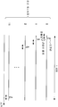
또한, 도 1에 나타내는 것처럼, 복수 이동국으로부터의 복수의 응답 신호를 ZC(Zadoff-Chu)계열 및 월시(Walsh) 계열을 이용해 확산함으로써 코드다중하는 것이 검토되고 있다(비특허 문헌 1 참조). 도 1에 있어서 (W0, W1, W2, W3)는 계열 길이 4인 월시 계열을 나타낸다. 도 1에 나타내는 바와 같이, 이동국에서는 ACK 또는 NACK의 응답 신호가, 우선 주파수축 상에서 ZC계열(계열 길이 12)에 의해 1 심볼내에 1차 확산된다. 그 다음에 1차 확산 후의 응답 신호를 W0~W3에 각각 대응시켜 IFFT(Inverse Fast Fourier Transform)된다. 주파수축 상에서 계열 길이 12인 ZC계열에 의해 확산된 응답 신호는 이 IFFT에 의해 시간축상의 계열 길이 12의 ZC계열로 변환된다. 그리고, IFFT 후의 신호가 다시 월시 계열(계열 길이 4)을 이용해 2차 확산된다. 즉, 1개의 응답 신호는 4개의 심볼 S0~S3에 각각 배치된다. 다른 이동국에서도 마찬가지로, ZC계열 및 월시 계열을 이용해 응답 신호가 확산된다. 단, 다른 이동국간에서는 시간축상에서의 순환 시프트(Cyclic Shift)량이 서로 다른 ZC계열, 또는 서로 다른 월시 계열이 이용된다. 여기서는 ZC계열의 시간축상에서의 계열 길이가 12이기 때문에, 동일 ZC계열로부터 생성되는 순환 시프트량 0~11인 12개 ZC계열을 이용할 수 있다. 또, 월시 계열의 계열 길이가 4이기 때문에, 서로 다른 4개의 월시 계열을 이용할 수 있다. 따라서, 이상적인 통신 환경에서는 최대 48(12×4) 이동국으로부터의 응답 신호를 코드다중할 수 있다. Also, as shown in Fig. 1, it has been studied to code-multiplex a plurality of response signals from a plurality of mobile stations by using ZC (Zadoff-Chu) series and Walsh series to code-multiplex (see Non-Patent Document 1). In FIG. 1, (W 0 , W 1 , W 2 , W 3 ) represents a Walsh sequence having a sequence length of 4. As shown in Fig. 1, in the mobile station, the ACK or NACK response signal is primarily spread on the frequency axis by a ZC sequence (sequence length 12) within one symbol. Then, the response signals after the first-order diffusion are subjected to Inverse Fast Fourier Transform (IFFT) in association with W 0 to W 3 , respectively. The response signal diffused by the ZC sequence having a sequence length of 12 on the frequency axis is converted into a ZC sequence having a sequence length of 12 on the time axis by this IFFT. Then, the IFFT-processed signal is secondarily diffused again using the Walsh sequence (sequence length 4). That is, one response signal is allocated to each of the four symbols S 0 to S 3 . Likewise, in other mobile stations, the response signal is spread using the ZC sequence and the Walsh sequence. However, ZC sequences different in cyclic shift amount on the time axis or different Walsh sequences are used between different mobile stations. Here, since the sequence length on the time axis of the ZC sequence is 12, 12 ZC sequences having a cyclic shift amount of 0 to 11 generated from the same ZC sequence can be used. In addition, since the sequence length of the Walsh sequence is 4, four different Walsh sequences can be used. Therefore, response signals from up to 48 (12 x 4) mobile stations can be code-multiplexed in an ideal communication environment.
여기서, 동일 ZC계열로부터 생성되는 순환 시프트량이 서로 다른 ZC계열간에서의 상호 상관은 0이 된다. 따라서, 이상적인 통신 환경에서는 도 2에 나타내는 것처럼, 순환 시프트량이 서로 다른 ZC계열(순환 시프트량 0~11)로 각각 확산되어 코드다중된 복수의 응답 신호는 기지국에서의 상관 처리에 의해 시간축상에서 부호간 간섭없이 분리할 수 있다. Here, the cross-correlation between ZC sequences having different cyclic shift amounts generated from the same ZC sequence is zero. Therefore, in an ideal communication environment, as shown in Fig. 2, a plurality of response signals spread and code-multiplexed into ZC sequences (
또한, 3GPP LTE(3rd Generation Partnership Protocol Long Term Evolution)의 PUCCH에서는 상술한 ACK/NACK 신호뿐만이 아니라, CQI(Channel Quality Indicator) 신호도 코드다중한다. ACK/NACK 신호는 도 1에 나타낸 것처럼, 1 심볼 정보이지만, CQI 신호는 5 심볼 정보다. 도 3에 나타내는 것처럼, 이동국은 CQI 신호를 계열 길이 12, 순환 시프트량 P인 ZC계열에 의해 확산하고, 확산한 CQI 신호를 IFFT 하여 송신한다. 이와 같이, CQI 신호에는 월시 계열이 적용되지 않기 때문에, 기지국에서는 ACK/NACK 신호와 CQI 신호의 분리에 월시 계열을 이용할 수 없다. 그래서, 기지국에서는 다른 순환 시프트에 대응하는 ZC계열을 이용하여 확산된 ACK/NACK 신호와 CQI 신호를 ZC계열로 역확산함으로써, ACK/NACK 신호와 CQI 신호를 거의 부호간 간섭없이 분리할 수 있다. In the PUCCH of the 3GPP LTE (3rd Generation Partnership Protocol Long Term Evolution), not only the ACK / NACK signal but also the CQI (Channel Quality Indicator) signal is code-multiplexed. The ACK / NACK signal is one symbol information as shown in FIG. 1, but the CQI signal is five symbol information. As shown in Fig. 3, the mobile station spreads the CQI signal by the ZC sequence having the
그렇지만, 이동국에서의 송신 타이밍 어긋남, 멀티 패스에 의한 지연파, 주파수 오프셋(offset) 등의 영향에 의해, 복수 이동국으로부터의 복수 ACK/NACK 신호 및 CQI 신호는 기지국에 동시에 도달한다고는 할 수 없다. ACK/NACK 신호의 경우를 예로 들면, 도 4에 나타내는 것처럼, 순환 시프트량 0인 ZC계열로 확산된 ACK/NACK 신호의 송신 타이밍이 정상적인 송신 타이밍보다 지연된 경우는 순환 시프트량 0의 ZC계열의 상관 피크가 순환 시프트량 1의 ZC계열의 검출창에 나타나 버린다. 또한, 도 5에 나타내는 것처럼, 순환 시프트량 0의 ZC계열로 확산된 ACK/NACK에 지연파가 있을 경우에는 그 지연파에 의한 간섭 리크가 순환 시프트량 1의 ZC계열의 검출창에 나타나 버린다. 즉, 이러한 경우에는 순환 시프트량 1의 ZC계열이 순환 시프트량 0의 ZC계열로부터의 간섭을 받는다. 따라서, 이러한 경우에는 순환 시프트량 0의 ZC계열로 확산된 ACK/NACK 신호와 순환 시프트량 1의 ZC계열로 확산된 ACK/NACK 신호의 분리 특성이 열화한다. 즉, 서로 인접하는 순환 시프트량의 ZC계열을 이용하면, ACK/NACK 신호의 분리 특성이 열화할 가능성이 있다. However, a plurality of ACK / NACK signals and CQI signals from a plurality of mobile stations do not reach the base station at the same time due to transmission timing shifts in the mobile station, delay waves caused by multipath, frequency offset, and the like. In the case of the ACK / NACK signal, as shown in FIG. 4, when the transmission timing of the ACK / NACK signal spread by the ZC sequence with the cyclic shift amount of 0 is delayed from the normal transmission timing, the ZC sequence correlation The peak appears in the detection window of the ZC sequence with the
그래서, 종래는 ZC계열의 확산을 이용해 복수의 응답 신호를 코드다중할 때에는 ZC계열간에서의 부호간 간섭이 발생하지 않을 정도의 충분한 순환 시프트량의 차(差)(순환 시프트 간격)를 ZC계열 사이에 마련하고 있다. 예를 들면, ZC계열간의 순환 시프트량의 차를 2로 하여 순환 시프트량 0~11의 12개 ZC계열 중, 순환 시프트량 0, 2, 4, 6, 8, 10인 6개 ZC계열만을 응답 신호의 1차 확산에 이용한다. 따라서, 계열 길이가 4인 월시 계열을 응답 신호의 2차 확산에 이용할 경우에는 최대 24(6×4) 이동국으로부터의 응답 신호를 코드다중할 수 있다. Therefore, conventionally, when a plurality of response signals are code-multiplexed by using ZC-based spreading, a difference (cyclic shift interval) of a sufficient cyclic shift amount such that intersymbol interference does not occur between ZC sequences is referred to as a ZC sequence Respectively. For example, only the 6 ZC sequences having the
비특허 문헌 2에는 이동국으로부터의 응답 신호에 대해서, 순환 시프트량 0, 2, 4, 6, 8, 10인 6개 ZC계열을 이용해 1차 확산을 행하고, 계열 길이 3인 월시 계열을 이용해 2차 확산을 행하는 예를 개시하고 있다. 도 6은 비특허 문헌 2에 기재된 예에 있어서, ACK/NACK 신호의 송신용(이하, 간단히 「ACK/NACK용」이라고 함)으로 각 이동국에 할당할 수 있는 CCE의 배치를 메시 구조로 나타낸 도면이다. 여기에서는 CCE 번호와 ZC계열의 순환 시프트량 및 월시 계열 번호에 의해 정의되는 PUCCH 번호가 1 대 1로 대응화되어 있는 것으로 한다. 즉, CCE#1과 PUCCH#1, CCE#2와 PUCCH#2, CCE#3과 PUCCH#3…이 각각 대응하는 것으로 한다(이하 동일). 도 6에 있어서, 가로축은 ZC계열의 순환 시프트량을 나타내고, 세로축은 월시 계열의 번호를 나타낸다. 월시 계열 #0과 #2는 부호간 간섭이 매우 발생하기 어렵기 때문에, 도 6에 나타내는 것처럼, 월시 계열 #0으로 2차 확산된 CCE와, 월시#2로 2차 확산된 CCE는 순환 시프트량이 동일한 ZC계열을 이용한다.
In
상술한 바와 같이, 3GPP LTE의 PUCCH에서는 ACK/NACK 신호 뿐만이 아니라, CQI 신호도 코드다중한다. 따라서, 도 6에 나타낸 순환 시프트 간격 2의 메시 구조를 가지는 CCE 중, 예를 들면 순환 시프트량 3 및 순환 시프트량 4의 ZC계열을 이용하는 CCE를 CQI용으로 하고, ACK/NACK용으로 사용하지 않도록 하는 것을 생각해 볼 수 있다. 이러한, ACK/NACK용 및 CQI용으로 할당할 수 있는 CCE의 배치를 도 7에 나타낸다. 도 7에 나타내는 메시 구조는 CCE#3 또는 CCE#15와 CCE#9의 순환 시프트 간격이 1이 되어 버려, ZC계열간에서의 부호간 간섭이 크게 되어 버리는 문제가 있다. As described above, not only the ACK / NACK signal but also the CQI signal is code-multiplexed in the PUCCH of the 3GPP LTE. Therefore, among the CCEs having the mesh structure of the
본 발명의 목적은 코드다중되는 ACN/NACK 신호와 CQI 신호의 부호간 간섭을 억제할 수 있는 무선 통신 장치 및 응답 신호 확산 방법을 제공하는 것이다.
An object of the present invention is to provide a radio communication apparatus and a response signal spreading method capable of suppressing code-to-code interference of code multiplexed ACN / NACK signals and CQI signals.
본 발명의 무선 통신 장치는 서로 다른 순환 시프트량에 의해 서로 분리할 수 있는 복수의 제 1 계열 중 어느 하나를 이용해서 제 1 응답 신호 또는 제 2 응답 신호를 1차 확산하는 제 1 확산 수단과, 1차 확산 후의 상기 제 1 응답 신호를 복수의 제 2 계열 중 어느 하나를 이용하여 2차 확산하는 제 2 확산 수단과, 복수 이동국으로부터의 상기 제 1 응답 신호와 상기 제 2 응답 신호의 순환 시프트량의 차의 최소값이, 상기 복수 이동국으로부터의 상기 제 2 응답 신호간의 순환 시프트량의 차의 최소값 이상이 되도록, 상기 제 1 확산 수단 및 상기 제 2 확산 수단을 제어하는 제어 수단을 구비하는 구성을 취한다.
The radio communication apparatus of the present invention includes first spreading means for first spreading a first response signal or a second response signal using any one of a plurality of first series that can be separated from each other by different cyclic shift amounts, Second spreading means for secondarily diffusing the first response signal after first spreading by using any one of the plurality of second sequences, second spreading means for spreading the cyclic shift amount of the first response signal and the second response signal from a plurality of mobile stations And control means for controlling the first spreading means and the second spreading means so that the minimum value of the difference between the first response signal and the second response signal is equal to or larger than a minimum value of the difference between the cyclic shift amounts between the second response signals from the plurality of mobile stations do.
본 발명에 의하면, 코드다중되는 ACK/NACK 신호와 CQI 신호의 부호간 간섭을 억제할 수 있다.
According to the present invention, it is possible to suppress the intersymbol interference between the code multiplexed ACK / NACK signal and the CQI signal.
도 1은 응답 신호의 확산 방법을 나타내는 도면(종래),
도 2는 ZC계열로 확산된 응답 신호의 상관 처리를 나타내는 도면(이상적인 통신 환경일 경우),
도 3은 CQI 신호의 확산 방법을 나타내는 도면(종래),
도 4는 ZC계열로 확산된 응답 신호의 상관 처리를 나타내는 도면(송신 타이밍의 어긋남이 있는 경우),
도 5는 ZC계열로 확산된 응답 신호의 상관 처리를 나타내는 도면(지연파가 있는 경우),
도 6은 ZC계열과 월시 계열과 CCE의 대응을 나타내는 도면(종래, 그 중 1),
도 7은 ZC계열과 월시 계열과 CCE의 대응을 나타내는 도면(종래, 그 중 1),
도 8은 본 발명의 실시예 1에 따른 기지국의 구성을 나타내는 도면,
도 9는 본 발명의 실시예 1에 따른 이동국의 구성을 나타내는 도면,
도 10은 본 발명의 실시예 1에 따른 각 이동국용 PUCCH에 대응하는 CCE를 나타내는 도면,
도 11은 본 발명의 실시예 1에 따른 각 이동국용 PUCCH에 대응하는 CCE의 베리에이션을 나타내는 도면,
도 12는 본 발명의 실시예 2에 따른 각 이동국용 PUCCH에 대응하는 CCE를 나타내는 도면,
도 13은 본 발명의 실시예 2에 따른 각 이동국용 PUCCH에 대응하는 CCE의 베리에이션을 나타내는 도면,
도 14는 본 발명의 실시예 3에 따른 각 이동국용 PUCCH에 대응하는 CCE를 나타내는 도면,
도 15는 본 발명의 실시예 3에 따른 각 이동국용 PUCCH에 대응하는 CCE를 설명하기 위한 도면,
도 16은 본 발명의 실시예 3에 따른 각 이동국용 PUCCH에 대응하는 CCE를 설명하기 위한 도면,
도 17은 본 발명의 실시예 3에 따른 각 이동국용 PUCCH에 대응하는 CCE의 베리에이션을 나타내는 도면이다. 1 is a diagram showing a diffusion method of a response signal (conventional), FIG.
2 is a diagram showing a correlation process of a response signal spread in a ZC sequence (in an ideal communication environment)
3 is a diagram showing a method of spreading a CQI signal (conventional), FIG.
4 is a diagram showing a correlation process of a response signal spread in a ZC sequence (when there is a shift in transmission timing)
5 is a diagram showing a correlation process of a response signal diffused in the ZC sequence (when there is a delayed wave)
6 is a diagram showing a correspondence between the ZC sequence, the Walsh sequence and the CCE (1 in the prior art)
7 is a diagram showing correspondence between a ZC sequence, a Walsh sequence and a CCE (1 in the prior art)
8 is a diagram showing a configuration of a base station according to
9 is a diagram showing the configuration of a mobile station according to
10 is a diagram showing a CCE corresponding to each PUCCH for each mobile station according to
11 is a diagram showing a variation of CCEs corresponding to PUCCHs for respective mobile stations according to
12 is a diagram showing a CCE corresponding to each PUCCH for each mobile station according to
13 is a diagram showing a variation of CCEs corresponding to PUCCHs for respective mobile stations according to
14 is a diagram showing a CCE corresponding to each PUCCH for each mobile station according to
15 is a diagram for explaining a CCE corresponding to each PUCCH for each mobile station according to
16 is a diagram for explaining a CCE corresponding to each PUCCH for each mobile station according to
17 is a diagram showing a variation of CCEs corresponding to PUCCHs for respective mobile stations according to
이하, 본 발명의 실시예에 대해서, 첨부 도면을 참조하여 상세하게 설명한다.
Hereinafter, embodiments of the present invention will be described in detail with reference to the accompanying drawings.
(실시예 1)(Example 1)
본 발명의 실시예 1에 따른 기지국(100)의 구성을 도 8에 나타내고, 본 발명의 실시예 1에 따른 이동국(200)의 구성을 도 9에 나타낸다. The configuration of the
또한, 설명이 번잡하게 되는 것을 피하기 위해, 도 8에서는 본 발명과 밀접하게 관련된 하향 회선 데이터의 송신 및 그 하향 회선 데이터에 대한 ACK/NACK 신호의 상향 회선에서의 수신과 관계되는 구성부를 나타내고, 상향 회선 데이터의 수신과 관계되는 구성부의 도면 표시 및 설명을 생략한다. 마찬가지로, 도 9에서는 본 발명과 밀접하게 관련된 하향 회선 데이터의 수신 및 그 하향 회선 데이터에 대한 ACK/NACK 신호의 상향 회선에서의 송신과 관계되는 구성부를 나타내며, 상향 회선 데이터의 송신과 관계되는 구성부의 도면 표시 및 설명을 생략한다. In order to avoid complication of explanation, FIG. 8 shows the constituent parts related to the transmission of downlink data closely related to the present invention and the reception of the ACK / NACK signal on the uplink on the downlink data, The display and description of the constituent parts related to the reception of the line data will be omitted. Likewise, FIG. 9 shows components related to reception of downlink data closely related to the present invention and transmission of an ACK / NACK signal in the uplink on the downlink data, The illustration and description of the drawings are omitted.
또한, 이하의 설명에서는 1차 확산에 ZC계열을 이용하고, 2차 확산에 월시 계열을 이용하는 경우에 대해서 설명한다. 그러나, 1차 확산에는 ZC계열 이외의, 서로 다른 순환 시프트량에 의해 서로 분리할 수 있는 계열을 이용해도 좋다. 마찬가지로, 2차 확산에는 월시 계열 이외의 직교 계열을 이용해도 좋다. In the following description, a ZC sequence is used for the primary diffusion and a Walsh sequence is used for the secondary diffusion. However, a series that can be separated from each other by different cyclic shift amounts other than the ZC series may be used for the primary diffusion. Likewise, orthogonal sequences other than the Walsh sequence may be used for the secondary diffusion.
또한, 이하의 설명에서는 계열 길이 12인 ZC계열 및 계열 길이 3인 월시 계열(W0, W1, W2)을 이용하는 경우에 대해서 설명한다. 그러나, 본 발명은 이러한 계열 길이에 한정되지 않는다. In the following description, a case is described in which a ZC sequence with a sequence length of 12 and a Walsh sequence (W 0 , W 1 , W 2 ) with a sequence length of 3 are used. However, the present invention is not limited to such a sequence length.
또한, 이하의 설명에서는 순환 시프트량 0~11인 12개 ZC계열을 각각 ZC#0~ZC#11이라고 표기하고, 계열 번호 0~2인 3개 월시 계열을 각각 W#0~W#2라고 표기한다. In the following description, twelve ZC sequences having a cyclic shift amount of 0 to 11 are denoted as
또한, 이하의 설명에서는 L1/L2CCH#1이 CCE#1, L1/L2CCH#2가 CCE#2, L1/L2CCH#3이 CCE#3, L1/L2CCH#4가 CCE#4 및 CCE#5, L1/L2CCH#5가 CCE#6 및 CCE#7, L1/L2CCH#6이 CCE#8~CCE#11…을 각각 점유하는 것으로 한다. In the following description, L1 /
또한, 이하의 설명에서는 CCE 번호와, ZC계열의 순환 시프트량 및 월시 계열 번호에 의해 정의되는 PUCCH 번호가 1 대 1로 대응화되어 있는 것으로 한다. 즉, CCE#1과 PUCCH#1, CCE#2와 PUCCH#2, CCE#3과 PUCCH#3…이 각각 대응하는 것으로 한다. In the following description, it is assumed that the CCE number, the cyclic shift amount of the ZC sequence, and the PUCCH number defined by the Walsh sequence number are mapped one to one. That is,
또한, 전술한 것처럼, 이동체 통신에 있어서 하향 회선의 통신 리소스를 효율 좋게 사용하기 위해, 이동국은 자국으로의 L1/L2CCH 제어 정보가 매핑되어 있는 물리 리소스에 대응하는 CCE로부터, 자국으로부터의 응답 신호의 송신에 이용하는 PUCCH를 판정한다. 따라서, 본 실시예에 따른 기지국(100)은 각 이동국용 PUCCH로서 적합한 CCE로 되어있는 L1/L2CCH를 각 이동국에 할당할 필요가 있다. In addition, as described above, in order to efficiently use downlink communication resources in mobile communication, the mobile station transmits a response signal from the CCE corresponding to the physical resource to which the L1 / L2 CCH control information to its own station is mapped And determines the PUCCH to be used for transmission. Therefore, the
도 8에 나타내는 기지국(100)에 있어서, 제어 정보 생성부(101)는 리소스 할당 결과를 통지하기 위한 제어 정보를 이동국마다 생성하여 제어 채널 할당부(102) 및 부호화부(103)에 출력한다. 이동국별 제어 정보에는 어느 이동국앞으로의 제어 정보인지를 나타내는 이동국 ID 정보가 포함된다. 예를 들면, 제어 정보 통지 대상 이동국의 ID번호로 마스킹된 CRC가 이동국 ID 정보로서 제어 정보에 포함된다. 이동국별 제어 정보는 부호화부(103)에서 부호화되고, 변조부(104)에서 변조되어 매핑부(108)에 입력된다. In the
제어 채널 할당부(102)는 제어 정보를 통지하기 위해 필요한 CCE수에 따라, 각 이동국에 대해서 복수 L1/L2CCH 중 어느 하나의 L1/L2CCH를 할당한다. 여기서, 제어 채널 할당부(102)는 각 이동국용 PUCCH에 대응하는 CCE를 참조하여 L1/L2CCH를 각 이동국에 할당한다. 각 이동국용 PUCCH에 대응하는 CCE의 상세한 것에 대해서는 후술한다. 제어 채널 할당부(102)는 할당한 L1/L2CCH에 대응하는 CCE 번호를 매핑부(108)에 출력한다. 예를 들면, 이동국#1로의 제어 정보 통지에 필요한 CCE수가 1이기 때문에 이동국#1에 L1/L2CCH#1이 할당된 경우에는 제어 정보 생성부(101)는 CCE 번호#1을 매핑부(108)에 출력한다. 또, 이동국#1로의 제어 정보의 통지에 필요한 CCE수가 4이기 때문에 이동국#1에 L1/L2CCH#6이 할당된 경우에는 제어 정보 생성부(101)는 CCE 번호#8~#11을 매핑부(108)에 출력한다. The control
한편, 부호화부(105)는 각 이동국으로의 송신 데이터(하향 회선 데이터)를 부호화하여 재송(再送) 제어부(106)에 출력한다. On the other hand, the
재송 제어부(106)는 첫 회 송신시에는 부호화 후(後)의 송신 데이터를 이동국별로 보지(保持)함과 아울러 변조부(107)에 출력한다. 재송 제어부(106)는 각 이동국으로부터의 ACK이 판정부(118)로부터 입력될 때까지 송신 데이터를 보지한다. 또, 재송 제어부(106)는 각 이동국으로부터의 NACK이 판정부(118)로부터 입력된 경우, 즉, 재송시에는 그 NACK에 대응하는 송신 데이터를 변조부(107)에 출력한다. The
변조부(107)는 재송 제어부(106)로부터 입력되는 부호화 후의 송신 데이터를 변조하여 매핑부(108)에 출력한다. The
매핑부(108)는 제어 정보의 송신시에는 변조부(104)로부터 입력되는 제어 정보를 제어 채널 할당부(102)로부터 입력되는 CCE 번호에 따라 물리 리소스에 매핑하여 IFFT부(109)에 출력한다. 즉, 매핑부(108)는 이동국별 제어 정보를, OFDM 심볼을 구성하는 복수의 서브캐리어에 있어서 CCE 번호에 대응하는 서브캐리어에 매핑한다. The
한편, 하향 회선 데이터의 송신시에는 매핑부(108)는 리소스 할당 결과에 따라 각 이동국으로의 송신 데이터를 물리 리소스에 매핑하여 IFFT부(109)에 출력한다. 즉, 매핑부(108)는 각 이동국에 대한 송신 데이터를, 리소스 할당 결과에 따라 OFDM 심볼을 구성하는 복수 서브캐리어 중 어느 하나에 매핑한다. On the other hand, at the time of transmitting the downlink data, the
IFFT부(109)는 제어 정보 또는 송신 데이터가 매핑된 복수 서브캐리어에 대해서 IFFT를 행하여 OFDM 심볼을 생성해, CP(Cyclic Prefix) 부가부(110)에 출력한다. The
CP 부가부(110)는 OFDM 심볼의 후미 부분과 동일한 신호를 CP로서 OFDM 심볼의 선두에 부가한다. The
무선 송신부(111)는 CP 부가 후의 OFDM 심볼에 대해 D/A 변환, 증폭 및 업 컨버트 등의 송신 처리를 행하여 안테나(112)로부터 이동국(200)(도 9)에 송신한다. The
한편, 무선 수신부(113)는 이동국(200)으로부터 송신된 신호를 안테나(112)를 경유하여 수신하고, 수신 신호에 대해 다운 컨버트, A/D 변환 등의 수신 처리를 행한다. 또한, 수신 신호에는 어느 이동국으로부터 송신된 ACK/NACK 신호와 다른 이동국으로부터 송신된 CQI 신호가 코드다중되어 있다. On the other hand, the
CP 제거부(114)는 수신 처리 후의 신호에 부가되어 있는 CP를 제거한다. The
상관 처리부(115)는 CP 제거부(114)로부터 입력되는 신호와, 이동국(200)에 있어서 1차 확산에 이용된 ZC계열과의 상관값을 구한다. 즉, 상관 처리부(115)는 ACK/NACK 신호에 할당하고 있던 순환 시프트량에 대응하는 ZC계열을 이용해서 구한 상관 결과와, CQI 신호에 할당하고 있던 순환 시프트량에 대응하는 ZC계열을 이용해서 구한 상관 결과를 분리부(116)에 출력한다. The
분리부(116)는 상관 처리부(115)로부터 입력되는 상관값에 기초하여, ACK/NACK 신호를 역확산부(117)에 출력하고, CQI 신호를 복조부(119)에 출력한다. The
역확산부(117)는 분리부(116)로부터 입력되는 ACK/NACK 신호를 이동국(200)에 있어서 2차 확산에 이용된 월시 계열로 역확산하고, 역확산 후의 신호를 판정부(118)에 출력한다. The
판정부(118)는 시간축상에 이동국별로 설정된 검출창을 이용해 이동국마다 상관 피크를 검출함으로써, 이동국별 ACK/NACK 신호를 검출한다. 예를 들면, 판정부(118)는 이동국#1용의 검출창#1에 상관 피크가 검출된 경우에는 이동국#1로부터의 ACK/NACK 신호를 검출하고, 이동국#2용의 검출창#2에 상관 피크가 검출된 경우에는 이동국#2로부터의 ACK/NACK 신호를 검출한다. 그리고, 판정부(118)는 검출된 ACK/NACK 신호가 ACK 또는 NACK 중 어느 것인지를 판정하여, 이동국별 ACK 또는 NACK을 재송 제어부(106)에 출력한다.The determining
복조부(119)는 분리부(116)로부터 입력되는 CQI 신호를 복조하고, 복호부(120)는 복조된 CQI 신호를 복호하여, CQI 신호를 출력한다. The
한편, 도 9에 나타내는 이동국(200)에 있어서, 무선 수신부(202)는 기지국(100)으로부터 송신된 OFDM 심볼을 안테나(201)를 경유하여 수신하고, OFDM 심볼에 대해서 다운 컨버트, A/D 변환 등의 수신 처리를 행한다. 9, the
CP 제거부(203)는 수신 처리 후의 OFDM 심볼에 부가되어 있는 CP를 제거한다. The
FFT(Fast Fourier Transform)부(204)는 OFDM 심볼에 대해서 FFT를 행하여 복수의 서브캐리어에 매핑되어 있는 제어 정보 또는 하향 회선 데이터를 획득해서, 이들을 추출부(205)에 출력한다. The FFT (Fast Fourier Transform)
추출부(205)는 제어 정보의 수신시에는 복수의 서브캐리어로부터 제어 정보를 추출하여 복조부(206)에 출력한다. 이 제어 정보는 복조부(206)에서 복조되고, 복호부(207)에서 복호되어 판정부(208)에 입력된다. The
한편, 하향 회선 데이터의 수신시에는 추출부(205)는 판정부(208)로부터 입력되는 리소스 할당 결과에 따라, 복수의 서브캐리어로부터 자국앞 하향 회선 데이터를 추출하여 복조부(210)에 출력한다. 이 하향 회선 데이터는 복조부(210)에서 복조되고, 복호부(211)에서 복호되어 CRC부(212)에 입력된다. On the other hand, upon receiving the downlink data, the extracting
CRC부(212)는 복호 후의 하향 회선 데이터에 대해서 CRC를 이용한 오류 검출을 행하고, CRC=OK(오류 없음)의 경우는 ACK을, CRC=NG(오류 있음)인 경우에는 NACK을 생성하고, 생성한 ACK/NACK 신호를 변조부(213)에 출력한다. 또, CRC부(212)는 CRC=OK(오류 없음)인 경우에는, 복호 후의 하향 회선 데이터를 수신 데이터로서 출력한다. The
판정부(208)는 복호부(207)로부터 입력된 제어 정보가 자국앞 제어 정보인지 아닌지를 블라인드 판정한다. 예를 들면, 판정부(208)는 자국의 ID번호로 디마스킹함으로써 CRC=OK(오류 없음)가 된 제어 정보를 자국앞으로의 제어 정보라고 판정한다. 그리고, 판정부(208)는 자국앞으로의 제어 정보, 즉, 자국에 대한 하향 회선 데이터의 리소스 할당 결과를 추출부(205)에 출력한다. 또, 판정부(208)는 자국앞 제어 정보가 매핑되어 있던 서브캐리어에 대응하는 CCE 번호로부터, 자국으로부터의 ACK/NACK 신호의 송신에 이용하는 PUCCH 번호를 판정하고, 판정 결과(PUCCH 번호)를 제어부(209)에 출력한다. 예를 들면, 상기 L1/L2CCH#1이 할당된 이동국(200)의 판정부(208)는 CCE#1에 대응하는 서브캐리어에 제어 정보가 매핑되어 있기 때문에, CCE#1에 대응하는 PUCCH#1을 자국용 PUCCH라고 판정한다. 또, 상기 L1/L2CCH#6이 할당된 이동국(200)의 판정부(208)는 CCE#8~CCE#11에 대응하는 서브캐리어에 제어 정보가 매핑되어 있기 때문에, CCE#8~CCE#11에 있어서 최소 번호인 CCE#8에 대응하는 PUCCH#8을 자국용 PUCCH라고 판정한다. The judging
제어부(209)는 판정부(208)로부터 입력된 PUCCH 번호에 따라, 확산부(214) 및 확산부(219)에서의 1차 확산에 이용하는 ZC계열의 순환 시프트량 및 확산부(216)에서의 2차 확산에 이용하는 월시 계열을 제어한다. 즉, 제어부(209)는 판정부(208)로부터 입력된 PUCCH 번호에 대응하는 순환 시프트량의 ZC계열을 확산부(214) 및 확산부(219)에 설정하고, 판정부(208)로부터 입력된 PUCCH 번호에 대응하는 월시 계열을 확산부(216)에 설정한다. 또, 제어부(209)는 미리 기지국(100)으로부터 CQI를 송신하도록 지시되어 있는 경우는 CQI 신호의 송신을 선택하고, CQI를 송신하도록 지시되어 있지않는 경우는 판정부(208)에 있어서 CRC=NG(오류있음)에 기초하여 생성된 ACK/NACK 신호를 송신하도록, 송신 신호 선택부(222)를 제어한다. The
변조부(213)는 CRC부(212)로부터 입력되는 ACK/NACK 신호를 변조하여 확산부(214)에 출력한다. 확산부(214)는 제어부(209)에 의해 설정된 ZC계열로 ACK/NACK 신호를 1차 확산하고, 1차 확산 후의 ACK/NACK 신호를 IFFT부(215)에 출력한다. IFFT부(215)는 1차 확산 후의 ACK/NACK 신호에 대해서 IFFT를 행하고, IFFT 후의 ACK/NACK 신호를 확산부(216)에 출력한다. 확산부(216)는 제어부(209)에 의해 설정된 월시 계열로 CP 부가 후의 ACK/NACK 신호를 2차 확산하고, 2차 확산 후의 ACK/NACK 신호를 CP 부가부(217)에 출력한다. CP 부가부(217)는 IFFT 후의 ACK/NACK 신호의 후미 부분과 동일한 신호를 CP로서 그 ACK/NACK 신호의 선두에 부가하여, 송신 신호 선택부(222)에 출력한다. 또한, 변조부(213), 확산부(214), IFFT부(215), 확산부(216) 및 CP 부가부(217)는 ACK/NACK 신호 송신 처리 수단으로서 기능한다. The
변조부(218)는 CQI 신호를 변조하여 확산부(219)에 출력한다. 확산부(219)는 제어부(209)에 의해 설정된 ZC계열로 CQI 신호를 확산하고, 확산 후의 CQI 신호를 IFFT부(220)에 출력한다. IFFT부(220)는 확산 후의 CQI 신호에 대해서 IFFT를 행하고, IFFT 후의 CQI 신호를 CP 부가부(221)에 출력한다. CP 부가부(221)는 IFFT 후의 CQI 신호의 후미 부분과 동일한 신호를 CP로서 그 CQI 신호의 선두에 부가하고, CP를 부가한 CQI 신호를 송신 신호 선택부(222)에 출력한다. The
송신 신호 선택부(222)는 제어부(209)의 설정에 따라, CP 부가부(217)로부터 입력되는 ACK/NACK 신호 또는 CP 부가부(221)로부터 입력되는 CQI 신호 중 어느 하나를 선택하고, 선택한 신호를 송신 신호로서 무선 송신부(223)에 출력한다. The
무선 송신부(223)는 송신 신호 선택부(222)로부터 입력된 송신 신호에 대해서 D/A 변환, 증폭 및 업 컨버트 등의 송신 처리를 행하여 안테나(201)로부터 기지국(100)(도 8)에 송신한다. The
이어서, 제어 채널 할당부(102)(도 8)에 있어서의 제어 채널 할당에 참조되는 각 이동국용 PUCCH에 대응하는 CCE의 상세한 것에 대해서 설명한다. Next, the details of the CCE corresponding to the PUCCH for each mobile station, which is referred to in the control channel allocation in the control channel assignment unit 102 (Fig. 8), will be described.
도 10은 각 이동국용 PUCCH에 대응하는 CCE를 나타내는 도면이다. 또한, 여기에서도, 상술한 것처럼, CCE번호와, ZC계열 순환 시프트량 및 월시 계열 번호에 의해 정의되는 PUCCH 번호가 1 대 1로 대응화되어 있는 것으로 한다. 즉, CCE#1과 PUCCH#1, CCE#2와 PUCCH#2, CCE#3과 PUCCH#3…이 각각 대응하는 것으로 한다. 10 is a diagram showing a CCE corresponding to each PUCCH for each mobile station. Also here, as described above, it is assumed that the CCE number, the ZC series cyclic shift amount, and the PUCCH number defined by the Walsh sequence number are associated with each other one by one. That is,
도 10에 있어서는 각 이동국용 PUCCH에 대응하는 CCE를, 이동국으로부터의 ACK/NACK용 CCE와, 이동국으로부터의 CQI용 CCE와, 사용불가 CCE로 분리하여 표시하고 있다. ACK/NACK용 CCE란, 이동국으로부터의 ACK/NACK 송신용 PUCCH에 대응하는 CCE이고, CQI용 CCE란, 이동국으로부터의 CQI 송신용 PUCCH에 대응하는 CCE이다. 또, 사용 불가 CCE란, 각 이동국용 PUCCH로서 사용 불가 PUCCH에 대응하는 CCE이다. In Fig. 10, the CCE corresponding to each PUCCH for the mobile station is divided into CCE for ACK / NACK from the mobile station, CCE for CQI from the mobile station, and unused CCE. The CCE for ACK / NACK is a CCE corresponding to a PUCCH for ACK / NACK transmission from a mobile station, and the CCE for CQI is a CCE corresponding to a PUCCH for CQI transmission from a mobile station. The unusable CCE is the CCE corresponding to the unavailable PUCCH as the PUCCH for each mobile station.
도 10에 있어서, CCE#1, #2, #4, #5, #6, #7, #9,…, #14, #16, #17, #18은 ACK/NACK용이고, 이러한 CCE의 순환 시프트 간격은 부호간 간섭이 발생하지 않을 정도로 2로 마련되어 있다. 또한, CCE#8은 CQI용이고, CCE#3, #15는 사용 불가 CCE이다. CCE#8을 CQI용으로 하고, CCE#3,#15를 사용 불가로 하는 이유는 ZC계열간의 순환 시프트 간격을 ZC계열간에서의 부호간 간섭이 발생하지 않을 정도로 2 이상으로 유지하기 위해서이다. 즉, CQI용 CCE와, 시간축상에서 CQI용 CCE의 뒤(도 10에 있어서는 가로축을 나타내는 화살표 방법)에 계속되는 제일 가까운 ACK/NACK용 CCE(여기에서는 CCE#9)의 순환 시프트 간격을 2 이상으로 유지함으로써, CQI 신호와 ACK/NACK의 부호간 간섭을 억제하기 때문이다. 또, 여기서, CCE#8과, CCE#2, #14의 ZC계열 순환 시프트 간격은 1이어서, 2보다 작아진다. 다만, 부호간 간섭은 지연파가 원인이기 때문에, CCE#8보다 시간축상에 있어 앞에 위치하는 CCE#2, #14에 대한 CCE#8의 간섭작용은 고려할 필요는 없다. 또한, 부호간 간섭은 지연파가 원인이라고 하는 동일한 이유에서, 반대로 CCE#8에 대한 CCE#2, #14의 간섭작용은 무시할 수 없다. 다만, 여기에서는 CQI 신호보다 ACK/NACK 신호가 스루풋에 대한 영향이 크기 때문에, CQI 신호의 송신 품질보다 ACK/NACK 신호의 송신 품질을 보다 중시하는 구조로 하고 있다. 즉, CQI용 CCE와, CQI용 CCE의 앞에 위치하는 ACK/NACK용 CCE의 순환 시프트 간격보다, CQI용 CCE와, CQI용 CCE의 뒤에 위치하는 ACK/NACK용 CCE의 순환 시프트 간격을 보다 크게 하고 있다. 10,
도 10에 나타내는 바와 같은 ACK/NACK용 또는 CQI용 PUCCH에 대응하는 CCE가 결정되면, 제어 채널 할당부(102)는 제어 정보를 통지하기 위해서 필요한 수에 따라, 이러한 CCE를 최소 번호로 하는 L1/L2CCH를 구성하여, 각 이동국에 할당한다. 10, the control
이와 같이, 본 실시예에 의하면, 기지국은 이동국으로부터의 ACK/NACK 송신용 PUCCH에 대한, CQI 송신용 PUCCH의 ZC계열 순환 시프트 간격을 소정값 이상으로 유지하도록 제어 채널 할당을 행하기 때문에, 코드다중되는 ACK/NACK 신호와 CQI 신호의 부호간 간섭을 억제할 수 있다. As described above, according to the present embodiment, since the base station performs the control channel allocation so that the ZC sequence cyclic shift interval of the PUCCH for CQI transmission for the PUCCH for ACK / NACK transmission from the mobile station is maintained at a predetermined value or more, The interference between the codes of the ACK / NACK signal and the CQI signal can be suppressed.
또한, 본 실시예에서는 1개의 순환 시프트량 3에 대응하는 CCE#8을 CQI용으로 하는 경우를 예로 들어 설명했지만, 본 발명은 이것으로 한정되지 않으며, 2개 이상의 순환 시프트량에 대응하는 CCE를 CQI용으로 해도 좋다. 예를 들면, 도(11)에 나타내는 바와 같이, 2개의 순환 시프트량 3 및 7에 대응하는 CCE#8 및 CCE#10을 CQI용으로 해도 좋다. 여기에서도, 후속하는 ACK/NACK용 CCE#9 및 #11에 대한 CQI용 CCE#8 및 CCE#10의 간격을 2 이상 유지하도록 하고 있다. In the present embodiment,
또, CQI용 CCE에 대응하는 순환 시프트량은 전체 셀 공통으로 해도 좋다.
The cyclic shift amount corresponding to the CCE for CQI may be common to all cells.
(실시예 2)(Example 2)
본 발명의 실시예 2에 따른 기지국 및 이동국은 실시예 1에 따른 기지국(도 8의 기지국(100) 참조) 및 이동국(도 9의 이동국(200) 참조)과 동일한 구성을 가지고 있고, 제어 채널 할당부(도 8에 나타낸 제어 채널 할당부(102))의 일부 처리에 있어서만 상위하다. The base station and the mobile station according to the second embodiment of the present invention have the same configuration as the base station (see the
도 12는 본 실시예에 따른 제어 채널 할당부에 참조되는 각 이동국용 PUCCH에 대응하는 CCE를 나타내는 도면이다. 또한, 도 12는 도 10과 기본적으로 동일하며, 여기에서는 차이점만을 설명한다. 12 is a diagram illustrating a CCE corresponding to each PUCCH for each mobile station, which is referred to in the control channel allocating unit according to the present embodiment. 12 is basically the same as FIG. 10, and only the differences are described here.
도 12에 나타내는 바와 같이, 본 실시예에 따른 기지국은 ACK/NACK용 CCE를 포함하는 순환 시프트량 가운데, 보다 적은 수의 ACK/NACK용 CCE를 포함하는 순환 시프트량의 뒤에 인접하는 CCE#3, #15를 CQI용으로 한다. 이렇게 함으로써, CQI용 CCE#3, #15에 대한 ACK/NACK용 CCE(여기에서는 CCE#8)의 수가 1개가 되어, CQI용 CCE에 대한 ACK/NACK용 CCE의 간섭을 억제할 수 있다. As shown in FIG. 12, the base station according to the present embodiment calculates
이와 같이, 본 실시예에 의하면, 기지국은 이동국으로부터의 ACK/NACK 송신용 PUCCH에 대한, CQI 송신용 PUCCH의 ZC계열 순환 시프트 간격을 소정값 이상으로 유지하면서, 보다 적은 수의 ACK/NACK용 PUCCH를 포함한 순환 시프트량의 뒤에 인접하는 PUCCH가 CQI용이 되도록 제어 채널 할당을 행하기 때문에, 코드다중되는 ACK/NACK 신호와 CQI 신호와의 부호간 간섭을 한층 더 억제할 수 있다. As described above, according to the present embodiment, the base station maintains a ZC sequence cyclic shift interval of a PUCCH for CQI transmission for a PUCCH for ACK / NACK transmission from a mobile station to a predetermined value or more, and transmits a smaller number of ACK / , The inter-code interference between the code multiplexed ACK / NACK signal and the CQI signal can be further suppressed.
또한, 본 실시예에서는 3개의 CCE를 CQI용 CCE 또는 사용 불가 CCE로 하는 경우를 예로 들어 설명했지만, 본 발명은 이것에 한정되지 않으며, 도(13)에 나타내는 바와 같이, 4개의 CCE를 CQI용 CCE 또는 사용 불가 CCE로 해도 좋다. 또, 5개 이상의 CCE를 CQI용 CCE 또는 사용불가 CCE로 해도 좋다.
In this embodiment, three CCEs are used as CCEs for CQIs or unavailable CCEs. However, the present invention is not limited to this, and as shown in FIG. 13, CCE or unusable CCE. In addition, five or more CCEs may be CCEs for CQIs or unusable CCEs.
(실시예 3)(Example 3)
본 발명의 실시예 3에 있어서는 각 이동국용 PUCCH간의 순환 시프트 간격이 3 이상일 경우의 제어 채널 할당에 대해서 설명한다. In the third embodiment of the present invention, the control channel allocation when the cyclic shift interval between the PUCCHs for the respective mobile stations is 3 or more will be described.
본 실시예 3에 따른 기지국 및 이동국은 실시예 1에 따른 기지국(도 8의 기지국(100) 참조) 및 이동국(도 9의 이동국(200) 참조)과 동일한 구성을 가지고 있고, 제어 채널 할당부(도 8에 나타낸 제어 채널 할당부(102))의 일부 처리에 있어서만 상위하다. The base station and the mobile station according to the third embodiment have the same configuration as that of the base station according to the first embodiment (see the
도 14는 본 실시예에 따른 제어 채널 할당부에 참조되는 각 이동국용 PUCCH에 대응하는 CCE를 나타내는 도면이다. 또한, 도 14는 도 10과 기본적으로 동일하며, 여기에서는 차이점만을 설명한다. FIG. 14 is a diagram illustrating a CCE corresponding to each PUCCH for each mobile station, which is referred to in the control channel assigning unit according to the present embodiment. 14 is basically the same as FIG. 10, and only the differences are described here.
도 14에 나타내는 바와 같이, 본 실시예에 따른 기지국은 ACK/NACK용 CCE와 CQI용 CCE의 순환 시프트 간격이 3 이상이 되도록, CCE#2, #10을 CQI용 CCE로 하고, CCE#6을 사용 불가 CCE로 한다. 14, the base station according to the present embodiment sets
도 14에 나타내는 등의 CCE 배치 방법은 다음과 같이 얻어진 것이다. 즉, 도(15)에 나타내는 등의, ACK/NACK용 CCE의 일부를 CQI용 CCE로 사용하고 싶을 경우에는 ACK/NACK용 CCE와 CQI용 CCE의 순환 시프트 간격이 3 이상이 되도록, 도(16)에 나타내는 것처럼, CCE#2를 CQI용 CCE로 하고 CCE#6,#10을 사용 불가 CCE로 하는 것이 생각된다. 그러나, 도(16)에 있어서, CQI용 CCE#2에 대한 ACK/NACK용 CCE#9의 간섭을 한층 더 억제하기 위해서, CCE#9~#12의 ZC계열 순환 시프트량을 「2」줄이면, 도 14가 얻어진다. The CCE arrangement method shown in FIG. 14 and the like is obtained as follows. That is, when it is desired to use a part of the CCE for ACK / NACK as the CCE for CQI, such as shown in FIG. 15, the cyclic shift interval between the CCE for ACK / NACK and the CCE for CQI is 3 or more , It is conceivable that
이와 같이, 본 실시예에 의하면, 기지국은 순환 시프트 간격이 3 이상인 CCE를 이동국에 할당하는 경우에도, 코드다중되는 ACK/NACK 신호와 CQI 신호의 부호간 간섭을 억제할 수 있다. As described above, according to the present embodiment, even when a base station allocates a CCE having a cyclic shift interval of 3 or more to a mobile station, interference between codes of code-multiplexed ACK / NACK signals and CQI signals can be suppressed.
또한, 본 실시예에서는 월시 길이가 3인 경우를 예로 들어 설명했지만, 본 발명은 이것으로 한정되지 않으며, 월시 길이가 4 이상인 경우에도 적용할 수 있다. 도 17은 월시 길이가 4로, 4개 월시 코드를 이용하는 경우에, 각 이동국용 PUCCH에 대응하는 CCE를 나타내는 도면이다. 도 17에 있어서는 ACK/NACK용 CCE와 CQI용 CCE의 순환 시프트 간격이 3 이상이 되도록, CCE#2, #10을 CQI용 CCE로 하고, CCE#6, #14를 사용 불가 CCE로 한다. In the present embodiment, the case where the wale length is 3 has been described as an example, but the present invention is not limited to this case, and the present invention is also applicable to a case where the waling length is 4 or more. 17 is a diagram showing a CCE corresponding to each PUCCH for each mobile station when a Walsh length is 4 and four Walsh codes are used. In FIG. 17,
이상, 본 발명의 실시예에 대해서 설명했다. The embodiments of the present invention have been described above.
본 발명에 따른 무선 통신 장치 및 응답 신호 확산 방법은 상기 각 실시예로 한정되지 않으며, 여러가지로 변경해서 실시하는 것이 가능하다. 예를 들면, 각 실시예는 적절하게 조합해서 실시하는 것이 가능하다. 예를 들면, 실시예 1 및 실시예 2에 있어서도, 계열 길이가 4개 이상인 월시 계열을 이용해도 좋다. The radio communication apparatus and the response signal spreading method according to the present invention are not limited to the above-described embodiments, but can be modified in various ways. For example, each of the embodiments can be appropriately combined. For example, also in the first and second embodiments, a Walsh sequence having a sequence length of four or more may be used.
또한, 상기 실시예에서는 복수 이동국으로부터의 복수의 응답 신호로서 ACK/NACK 신호와 CQI를 예로 들어 설명했지만, 본 발명은 이것으로 한정되지 않으며, ACK/NACK 신호 및 CQI 신호 이외의, 복수 이동국으로부터의 중요함이 다른 2 종류의 응답 신호, 이를테면 스케줄링 리퀘스트 신호와 ACK/NACK 신호를 코드다중할 경우에도 본 발명을 적용할 수 있다. In the above embodiment, ACK / NACK signals and CQIs are used as an example of a plurality of response signals from a plurality of mobile stations. However, the present invention is not limited to this, and other than ACK / NACK signals and CQI signals, The present invention can be applied to the case of code-multiplexing two types of response signals different in importance, for example, a scheduling request signal and an ACK / NACK signal.
또한, 이동국은 UE, 기지국은 Node B, 서브캐리어는 톤이라고 불리는 경우도 있다. 또한, CP는 가드 인터벌(Guard Interval:GI) 이라고 불리는 경우도 있다. The mobile station may be referred to as a UE, the base station as a Node B, and the subcarrier as a tone. The CP may also be referred to as a guard interval (GI).
또한, 오류 검출의 방법은 CRC에 한하지 않는다. Also, the method of error detection is not limited to CRC.
또한, 주파수 영역과 시간 영역 사이의 변환을 행하는 방법은 IFFT, FFT에 한하지 않는다. The method of performing the conversion between the frequency domain and the time domain is not limited to IFFT and FFT.
또한, 상기 실시예에서는 본 발명을 이동국에 적용하는 경우에 대해 설명했다. 그러나, 본 발명은 고정된 정지 상태의 무선 통신 단말 장치나, 기지국과의 사이에서 이동국과 동등한 동작을 하는 무선 통신 중계국 장치에 대해서도 적용할 수 있다. 즉, 본 발명은 모든 무선 통신 장치에 대해서 적용할 수 있다. In addition, in the above embodiment, the case where the present invention is applied to a mobile station has been described. However, the present invention can also be applied to a fixed stationary wireless communication terminal apparatus or a wireless communication relay station apparatus that performs an operation equivalent to that of a mobile station with a base station. That is, the present invention can be applied to all wireless communication devices.
또한, 상기 실시예에서는 본 발명을 하드웨어로 구성하는 경우를 예로 들어 설명했지만, 본 발명은 소프트웨어로 실현하는 것도 가능하다. In the above embodiment, the present invention is described by taking the case of hardware as an example, but the present invention can also be implemented by software.
또한, 상기 실시예의 설명에 이용한 각 기능 블록은 전형적으로는 집적 회로인 LSI로서 실현된다. 이들은 개별적으로 1 칩화되어도 좋고, 일부 또는 전부를 포함하도록 1 칩화되어도 좋다. 여기에서는 LSI라고 했지만, 집적도의 차이에 의해, IC, 시스템 LSI, 슈퍼 LSI, 울트라 LSI라고 불리는 경우도 있다. Each functional block used in the description of the embodiment is typically realized as an LSI which is an integrated circuit. They may be individually monolithic, or may be monolithic including some or all of them. Although it is referred to as an LSI here, it may be called an IC, a system LSI, a super LSI, or an ultra LSI due to the difference in integration degree.
또한, 집적 회로화의 수법은 LSI에 한하는 것은 아니며, 전용 회로 또는 범용 프로세서로 실현해도 좋다. LSI 제조 후에, 프로그램하는 것이 가능한 FPGA(Field Programmable Gate Array)나, LSI 내부의 회로 셀의 접속이나 설정을 재구성 가능한 리컨피규러블 프로세서를 이용해도 좋다. In addition, the method of making the integrated circuit is not limited to the LSI, and may be realized by a dedicated circuit or a general-purpose processor. An FPGA (Field Programmable Gate Array) that can be programmed after the LSI fabrication, or a reconfigurable processor capable of reconfiguring the connection and setting of the circuit cells in the LSI may be used.
또한, 반도체 기술의 진보 또는 파생하는 별개의 기술에 의해 LSI에 대체되는 집적 회로화의 기술이 등장하면, 당연히 그 기술을 이용해 기능 블록의 집적화를 행하여도 좋다. 바이오 기술의 적용 등이 가능성으로서 있을 수 있다. Also, if an integrated circuit technology to replace the LSI by the progress of semiconductor technology or a separate technology derived therefrom emerges, it is of course possible to integrate the functional blocks using the technique. Application of biotechnology, etc. may be possible.
2007년 8월 13일에 출원한 특허출원 2007-211102의 일본 출원에 포함되는 명세서, 도면 및 요약서의 개시 내용은 모두 본원에 원용된다.The disclosures of the specification, drawings and abstract included in the Japanese application of the patent application 2007-211102 filed on August 13, 2007 are all incorporated herein by reference.
(산업상의 이용 가능성)(Industrial availability)
본 발명은 이동체 통신 시스템 등에 적용할 수 있다.The present invention can be applied to a mobile communication system or the like.
Claims (14)
상기 ACK/NACK 신호 또는 상기 CQI 신호를 송신하는 송신부
를 갖고,
상기 확산부는, 상기 ACK/NACK 신호 또는 상기 CQI 신호를 구성하는 심볼마다, 상기 ACK/NACK 신호에 대해서는, 상기 복수의 순환 시프트량의 일부인, 인접하는 복수의 제 1 순환 시프트량 중 어느 하나를 이용하고, 상기 CQI 신호에 대해서는, 상기 일부 이외의 복수의 제 2 순환 시프트량 중 어느 하나를 이용하며,
상기 제 1 순환 시프트량과 상기 제 2 순환 시프트량 사이의 순환 시프트량은, 상기 ACK/NACK 신호 및 상기 CQI 신호 중 어느 쪽에도 이용되지 않는
무선 통신 장치.
A spreading unit for spreading an ACK / NACK signal or a CQI signal using a sequence defined by any one of a plurality of cyclic shift amounts;
A transmitter for transmitting the ACK / NACK signal or the CQI signal
Lt; / RTI &
Wherein the spreading unit uses any one of a plurality of adjacent first cyclic shift amounts that are a part of the plurality of cyclic shift amounts for the ACK / NACK signal for each symbol constituting the ACK / NACK signal or the CQI signal And the second cyclic shift amount other than the part is used for the CQI signal,
Wherein the cyclic shift amount between the first cyclic shift amount and the second cyclic shift amount is set so that a cyclic shift amount between the ACK / NACK signal and the CQI signal
Wireless communication device.
상기 ACK/NACK 신호 또는 상기 CQI 신호를 송신하는 송신부
를 갖고,
상기 확산부는, 상기 ACK/NACK 신호 또는 상기 CQI 신호를 구성하는 심볼마다, 상기 ACK/NACK 신호에 대해서는, 상기 복수의 순환 시프트량의 일부인, 인접하는 복수의 순환 시프트량 중 어느 하나를 이용하고, 상기 CQI 신호에 대해서는, 상기 인접하는 복수의 순환 시프트량과, 소정 간격으로 이격된 순환 시프트량을 이용하며,
상기 소정 간격은, 상기 ACK/NACK 신호에 대한 상기 인접하는 복수의 순환 시프트량의 최소 간격보다 큰
무선 통신 장치.
A spreading unit for spreading an ACK / NACK signal or a CQI signal using a sequence defined by any one of a plurality of cyclic shift amounts;
A transmitter for transmitting the ACK / NACK signal or the CQI signal
Lt; / RTI &
Wherein the spreading unit uses any one of a plurality of adjacent cyclic shift amounts which are a part of the plurality of cyclic shift amounts for the ACK / NACK signal for each symbol constituting the ACK / NACK signal or the CQI signal, Wherein the CQI signal uses a plurality of adjacent cyclic shift amounts and a cyclic shift amount spaced apart by a predetermined interval,
Wherein the predetermined interval is greater than a minimum interval of the adjacent plurality of cyclic shift amounts for the ACK /
Wireless communication device.
상기 소정 간격은 2인 무선 통신 장치.
3. The method of claim 2,
Wherein the predetermined interval is two.
상기 ACK/NACK 신호를 구성하는 심볼과 다른 무선 통신 장치로부터 송신되는 CQI 신호를 구성하는 심볼이, 또는 상기 CQI 신호를 구성하는 심볼과 다른 무선 통신 장치로부터의 ACK/NACK 신호를 구성하는 심볼이, 동일한 1심볼에 배치되는 무선 통신 장치.
3. The method according to claim 1 or 2,
A symbol constituting the ACK / NACK signal and a symbol constituting a CQI signal transmitted from another radio communication apparatus, or a symbol constituting an ACK / NACK signal from a radio communication apparatus different from the symbol constituting the CQI signal, And the same one symbol.
상기 ACK/NACK 신호와 다른 무선 통신 장치로부터 송신되는 CQI 신호가, 또는 상기 CQI 신호와 다른 무선 통신 장치로부터의 ACK/NACK 신호가, 동일 주파수 및 동일 슬롯의 리소스에 배치되는 무선 통신 장치.
3. The method according to claim 1 or 2,
Wherein a CQI signal transmitted from another radio communication apparatus is different from the ACK / NACK signal or an ACK / NACK signal transmitted from a radio communication apparatus different from the CQI signal is allocated to a resource of the same frequency and the same slot.
상기 ACK/NACK 신호가, 다른 무선 통신 장치로부터 송신되는 CQI 신호와 코드 다중되거나, 또는 상기 CQI 신호가, 다른 무선 통신 장치로부터 송신되는 ACK/NACK 신호와 코드 다중되는 무선 통신 장치.
3. The method according to claim 1 or 2,
Wherein the ACK / NACK signal is code-multiplexed with a CQI signal transmitted from another radio communication apparatus, or the CQI signal is code-multiplexed with an ACK / NACK signal transmitted from another radio communication apparatus.
상기 확산부는, 순환 시프트량으로 정의되는 상기 계열로서, 계열 길이가 12인 계열을 이용하는 무선 통신 장치.
3. The method according to claim 1 or 2,
Wherein the spreading section uses the sequence of the sequence length of 12 as the sequence defined by the cyclic shift amount.
복수의 직교 계열 중 어느 하나를 이용해서 상기 ACK/NACK 신호를 확산하는 제 2 확산부를 더 갖는 무선 통신 장치.
3. The method according to claim 1 or 2,
And a second spreader for spreading the ACK / NACK signal using any one of the plurality of orthogonal sequences.
상기 제 2 확산부는, 상기 직교 계열로서, 계열 길이가 4인 계열을 이용하는 무선 통신 장치.
9. The method of claim 8,
And the second spreading section uses the series having a sequence length of 4 as the orthogonal sequence.
상기 송신부는, 제어 채널을 이용해서 상기 ACK/NACK 신호 또는 상기 CQI 신호를 송신하고,
상기 확산부는, 상기 제어 채널로부터 특정되는 순환 시프트량으로 정의되는 상기 계열을 이용하는
무선 통신 장치.
3. The method according to claim 1 or 2,
Wherein the transmitter transmits the ACK / NACK signal or the CQI signal using a control channel,
Wherein the spreading unit uses the sequence defined by a cyclic shift amount specified from the control channel
Wireless communication device.
복수의 직교 계열 중 어느 하나를 이용해서 상기 ACK/NACK 신호를 확산하는 제 2 확산 처리
를 제어하는 집적 회로로서,
상기 제 1 확산 처리에 있어서, 상기 ACK/NACK 신호 또는 상기 CQI 신호를 구성하는 심볼마다, 상기 ACK/NACK 신호에 대해서는, 상기 복수의 순환 시프트량의 일부인, 인접하는 복수의 제 1 순환 시프트량 중 어느 하나가 이용되고, 상기 CQI 신호에 대해서는, 상기 일부 이외의 제 2 순환 시프트량 중 어느 하나가 이용되며, 상기 제 1 순환 시프트량과 상기 제 2 순환 시프트량 사이의 순환 시프트량은, 상기 ACK/NACK 신호 및 상기 CQI 신호 중 어느 쪽에도 이용되지 않는
집적 회로.
A first spreading process for spreading an ACK / NACK signal or a CQI signal using a sequence defined by any one of a plurality of cyclic shift amounts,
A second spreading process for spreading the ACK / NACK signal using any one of a plurality of orthogonal sequences
, The integrated circuit comprising:
In the first spreading process, for each of the symbols constituting the ACK / NACK signal or the CQI signal, for the ACK / NACK signal, among a plurality of adjacent first cyclic shift amounts which are a part of the plurality of cyclic shift amounts One of the first cyclic shift amount and the second cyclic shift amount is used for the CQI signal and the cyclic shift amount between the first cyclic shift amount and the second cyclic shift amount is used as the ACK / NACK signal and the CQI signal
integrated circuit.
복수의 직교 계열 중 어느 하나를 이용해서 상기 ACK/NACK 신호를 확산하는 제 2 확산 처리
를 제어하는 집적 회로로서,
상기 제 1 확산 처리에서, 상기 ACK/NACK 신호 또는 상기 CQI 신호를 구성하는 심볼마다, 상기 ACK/NACK 신호에 대해서는, 상기 복수의 순환 시프트량의 일부인, 인접하는 복수의 순환 시프트량 중 어느 하나가 이용되고, 상기 CQI 신호에 대해서는, 상기 인접하는 복수의 순환 시프트량과 소정 간격으로 이격된 순환 시프트량이 이용되며,
상기 소정 간격은, 상기 ACK/NACK 신호에 대한 상기 인접하는 복수의 순환 시프트량의 최소 간격보다 큰
집적 회로.
A first spreading process for spreading an ACK / NACK signal or a CQI signal using a sequence defined by any one of a plurality of cyclic shift amounts,
A second spreading process for spreading the ACK / NACK signal using any one of a plurality of orthogonal sequences
, The integrated circuit comprising:
Wherein, in the first spreading process, any one of a plurality of adjacent cyclic shift amounts which are a part of the plurality of cyclic shift amounts for the ACK / NACK signal for each symbol constituting the ACK / NACK signal or the CQI signal A cyclic shift amount which is spaced apart from the adjacent plurality of cyclic shift amounts by a predetermined interval is used for the CQI signal,
Wherein the predetermined interval is greater than a minimum interval of the adjacent plurality of cyclic shift amounts for the ACK /
integrated circuit.
복수의 직교 계열 중 어느 하나를 이용해서 상기 ACK/NACK 신호를 확산하는 제 2 확산 공정
을 갖고,
상기 제 1 확산 처리에서, 상기 ACK/NACK 신호 또는 상기 CQI 신호를 구성하는 심볼마다, 상기 ACK/NACK 신호에 대해서는, 상기 복수의 순환 시프트량의 일부인, 인접하는 복수의 제 1 순환 시프트량 중 어느 하나가 이용되고, 상기 CQI 신호에 대해서는, 상기 일부 이외의 제 2 순환 시프트량 중 어느 하나가 이용되며, 상기 제 1 순환 시프트량과 상기 제 2 순환 시프트량 사이의 순환 시프트량은, 상기 ACK/NACK 신호 및 상기 CQI 신호 중 어느 쪽에도 이용되지 않는
신호 확산 방법.
A first spreading step of spreading an ACK / NACK signal or a CQI signal using a sequence defined by any one of a plurality of cyclic shift amounts;
A second spreading step of spreading the ACK / NACK signal using any one of a plurality of orthogonal sequences;
Lt; / RTI &
Wherein in the first spreading process, for each of the symbols constituting the ACK / NACK signal or the CQI signal, for the ACK / NACK signal, any of a plurality of adjacent first cyclic shift amounts which are a part of the plurality of cyclic shift amounts One of the first cyclic shift amount and the second cyclic shift amount is used for the CQI signal and the cyclic shift amount between the first cyclic shift amount and the second cyclic shift amount is used as the ACK / NACK signal and the CQI signal
Signal spreading method.
복수의 직교 계열 중 어느 하나를 이용해서 상기 ACK/NACK 신호를 확산하는 제 2 확산 공정
을 갖고,
상기 제 1 확산 처리에서, 상기 ACK/NACK 신호 또는 상기 CQI 신호를 구성하는 심볼마다, 상기 ACK/NACK 신호에 대해서는, 상기 복수의 순환 시프트량의 일부인, 인접하는 복수의 순환 시프트량 중 어느 하나가 이용되고, 상기 CQI 신호에 대해서는, 상기 인접하는 복수의 순환 시프트량과 소정 간격으로 이격된 순환 시프트량이 이용되며,
상기 소정 간격은, 상기 ACK/NACK 신호에 대한 상기 인접하는 복수의 순환 시프트량의 최소 간격보다 큰
신호 확산 방법.A first spreading step of spreading an ACK / NACK signal or a CQI signal using a sequence defined by any one of a plurality of cyclic shift amounts;
A second spreading step of spreading the ACK / NACK signal using any one of a plurality of orthogonal sequences;
Lt; / RTI &
Wherein, in the first spreading process, any one of a plurality of adjacent cyclic shift amounts which are a part of the plurality of cyclic shift amounts for the ACK / NACK signal for each symbol constituting the ACK / NACK signal or the CQI signal A cyclic shift amount which is spaced apart from the adjacent plurality of cyclic shift amounts by a predetermined interval is used for the CQI signal,
Wherein the predetermined interval is greater than a minimum interval of the adjacent plurality of cyclic shift amounts for the ACK /
Signal spreading method.
Applications Claiming Priority (3)
| Application Number | Priority Date | Filing Date | Title |
|---|---|---|---|
| JPJP-P-2007-211102 | 2007-08-13 | ||
| JP2007211102 | 2007-08-13 | ||
| PCT/JP2008/002199 WO2009022466A1 (en) | 2007-08-13 | 2008-08-12 | Radio communication device and response signal diffusion method |
Related Child Applications (1)
| Application Number | Title | Priority Date | Filing Date |
|---|---|---|---|
| KR20137006025A Division KR101424066B1 (en) | 2007-08-13 | 2008-08-12 | Base station device, integrated circuit and communication method |
Publications (2)
| Publication Number | Publication Date |
|---|---|
| KR20100043223A KR20100043223A (en) | 2010-04-28 |
| KR101424064B1 true KR101424064B1 (en) | 2014-08-13 |
Family
ID=40350524
Family Applications (2)
| Application Number | Title | Priority Date | Filing Date |
|---|---|---|---|
| KR20137006025A KR101424066B1 (en) | 2007-08-13 | 2008-08-12 | Base station device, integrated circuit and communication method |
| KR20107003056A KR101424064B1 (en) | 2007-08-13 | 2008-08-12 | Radio communication device, integrated circuit and signal diffusion method |
Family Applications Before (1)
| Application Number | Title | Priority Date | Filing Date |
|---|---|---|---|
| KR20137006025A KR101424066B1 (en) | 2007-08-13 | 2008-08-12 | Base station device, integrated circuit and communication method |
Country Status (14)
| Country | Link |
|---|---|
| US (10) | US7965760B2 (en) |
| EP (8) | EP4113872A1 (en) |
| JP (10) | JP4512169B2 (en) |
| KR (2) | KR101424066B1 (en) |
| CN (4) | CN101785266B (en) |
| BR (1) | BRPI0823202B1 (en) |
| DK (2) | DK2451103T3 (en) |
| ES (6) | ES2476390T3 (en) |
| HK (2) | HK1215111A1 (en) |
| MX (1) | MX2010001406A (en) |
| NO (1) | NO2940910T3 (en) |
| PL (1) | PL2940910T3 (en) |
| RU (4) | RU2481711C2 (en) |
| WO (1) | WO2009022466A1 (en) |
Families Citing this family (18)
| Publication number | Priority date | Publication date | Assignee | Title |
|---|---|---|---|---|
| EP4113872A1 (en) * | 2007-08-13 | 2023-01-04 | Optis Wireless Technology, LLC | Radio communication device and response signal diffusion method |
| US9065646B2 (en) | 2008-02-04 | 2015-06-23 | Nokia Solutions And Networks Oy | ACK/NACK channelization for resource blocks containing both ACK/NACK and CQI |
| EP2320615B1 (en) | 2008-08-19 | 2013-06-19 | Electronics and Telecommunications Research Institute | Method and apparatus for transmitting acknowledgement and negative acknowledgement |
| WO2010124437A1 (en) * | 2009-04-27 | 2010-11-04 | 华为技术有限公司 | Receiving method for physical uplink control information, base station and relay device |
| EP2487852B1 (en) * | 2009-10-08 | 2018-08-08 | LG Electronics Inc. | Method and apparatus for transmitting an uplink control signal in a wireless communication system |
| SG187882A1 (en) * | 2010-08-16 | 2013-03-28 | Nokia Siemens Networks Oy | Randomization of block spread signals |
| WO2012044764A2 (en) | 2010-10-01 | 2012-04-05 | Research In Motion Limited | Orthogonal resource selection transmit diversity and resource assignment |
| US9844029B2 (en) * | 2010-11-09 | 2017-12-12 | Sharp Kabushiki Kaisha | ACK/NACK processing for a mobile station device, base station device, wireless communication system, wireless communication method, and integrated circuit |
| US10638464B2 (en) * | 2011-04-01 | 2020-04-28 | Futurewei Technologies, Inc. | System and method for transmission and reception of control channels in a communications system |
| US8908492B2 (en) | 2011-08-11 | 2014-12-09 | Blackberry Limited | Orthogonal resource selection transmit diversity and resource assignment |
| US8891353B2 (en) * | 2011-08-11 | 2014-11-18 | Blackberry Limited | Orthogonal resource selection transmit diversity and resource assignment |
| WO2013023170A1 (en) | 2011-08-11 | 2013-02-14 | Research In Motion Limited | Orthogonal resource selection transmit diversity and resource assignment |
| CN102355733B (en) * | 2011-09-30 | 2017-09-26 | 中兴通讯股份有限公司 | The sending method and user equipment of a kind of Physical Uplink Control Channel |
| US10841037B2 (en) * | 2013-01-22 | 2020-11-17 | Qualcomm Incorporated | Managing interference in a network |
| KR101987207B1 (en) | 2015-12-10 | 2019-06-10 | 엘지전자 주식회사 | A method for transmitting an uplink signal in a wireless communication system supporting a short transmission time interval and a device supporting the same |
| US10911191B2 (en) * | 2018-09-27 | 2021-02-02 | Centre Of Excellence In Wireless Technology | Method and apparatus for managing communication operations in orthogonal frequency division multiplexing system |
| US11877299B2 (en) * | 2020-03-05 | 2024-01-16 | Qualcomm Incorporated | Control channel resources for group-feedback in multi-cast |
| US20210399833A1 (en) * | 2020-06-19 | 2021-12-23 | Qualcomm Incorporated | Group feedback for multicast communications |
Family Cites Families (27)
| Publication number | Priority date | Publication date | Assignee | Title |
|---|---|---|---|---|
| US6028851A (en) | 1997-09-26 | 2000-02-22 | Telefonaktiebolaget L M Ericsson (Publ) | System and method for mobile assisted admission control |
| US6594238B1 (en) * | 1998-06-19 | 2003-07-15 | Telefonaktiebolaget Lm Ericsson (Publ) | Method and apparatus for dynamically adapting a connection state in a mobile communications system |
| EP1041850A1 (en) * | 1999-04-01 | 2000-10-04 | Nortel Matra Cellular | Method and apparatus for changing radio link configurations in a mobile telecommunications system with soft handover |
| CN1150709C (en) * | 2001-02-28 | 2004-05-19 | 信息产业部电信传输研究所 | Speed band-enlarging and-deenlarging method for two-stage code converter chips in CDMA cellular system |
| KR100837351B1 (en) * | 2002-04-06 | 2008-06-12 | 엘지전자 주식회사 | Update method for radio link parameter of mobile communication system |
| CN1774872A (en) | 2003-04-22 | 2006-05-17 | 美商内数位科技公司 | Method and system for integrating resource allocation between time division duplex and frequency division duplex in wireless communication systems |
| JP4482293B2 (en) | 2003-07-03 | 2010-06-16 | パナソニック株式会社 | Base station apparatus and transmission method |
| CN101646246B (en) | 2003-08-06 | 2013-01-16 | 松下电器产业株式会社 | Radio communication device and radio communication method |
| WO2005060127A1 (en) | 2003-12-19 | 2005-06-30 | Nokia Corporation | Selection of radio resources in a wireless communication device |
| JP4677988B2 (en) * | 2004-08-10 | 2011-04-27 | 日本電気株式会社 | Communication control method, radio communication system, base station, and mobile station |
| KR100594156B1 (en) | 2004-09-10 | 2006-06-28 | 삼성전자주식회사 | Preamble Sequence Transmit / Receive Method in Orthogonal Frequency Division Multiplexing System Using Multiple Input Multiple Output System |
| US20060067381A1 (en) | 2004-09-23 | 2006-03-30 | Chakravarthy Vasu D | Spectrum re-use employing transfer domain communications systems |
| RU2363103C2 (en) * | 2005-01-11 | 2009-07-27 | Нтт Докомо, Инк. | Method of controlling transmission speed, mobile station and radio network controller |
| CN101005326B (en) * | 2006-01-18 | 2014-05-07 | 华为技术有限公司 | Up resource distributing method and radio communication system |
| JP4875903B2 (en) | 2006-02-08 | 2012-02-15 | 富士フイルム株式会社 | Pigment dispersion composition and colored photosensitive composition |
| CN101098007A (en) * | 2006-06-27 | 2008-01-02 | 上海攀业氢能源科技有限公司 | Catalyzer slurry for producing fuel cell membrane electrode and process for production thereof |
| US8571120B2 (en) * | 2006-09-22 | 2013-10-29 | Texas Instruments Incorporated | Transmission of acknowledge/not acknowledge (ACK/NACK) bits and their embedding in the reference signal |
| WO2008053930A1 (en) | 2006-10-31 | 2008-05-08 | Kddi Corporation | Radio terminal and radio base station device |
| CN104821868B (en) * | 2007-04-30 | 2018-06-01 | 诺基亚通信公司 | Method for wireless communications and device |
| KR101494002B1 (en) | 2007-06-11 | 2015-02-16 | 삼성전자주식회사 | Apparatus and method for allocating resource in a wireless communication system and receving thereof |
| US8036166B2 (en) * | 2007-06-18 | 2011-10-11 | Nokia Corporation | Signaling of implicit ACK/NACK resources |
| US8169950B2 (en) * | 2007-06-21 | 2012-05-01 | Texas Instruments Incorporated | Selection of orthogonal covering sequences and phase ramped sequences |
| KR101481201B1 (en) * | 2007-07-30 | 2015-01-21 | 삼성전자주식회사 | Method and system for transmitting and receiving different signal types in communication systems |
| KR101457685B1 (en) * | 2007-08-10 | 2014-11-03 | 삼성전자주식회사 | Method and apparatus for transmitting and receiving ack/nack in cellular wireless communication systems |
| EP4113872A1 (en) | 2007-08-13 | 2023-01-04 | Optis Wireless Technology, LLC | Radio communication device and response signal diffusion method |
| US9065646B2 (en) * | 2008-02-04 | 2015-06-23 | Nokia Solutions And Networks Oy | ACK/NACK channelization for resource blocks containing both ACK/NACK and CQI |
| KR101783610B1 (en) * | 2010-04-21 | 2017-10-10 | 엘지전자 주식회사 | Apparatus and method of transmitting control information in wireless communication system |
-
2008
- 2008-08-12 EP EP22191291.8A patent/EP4113872A1/en active Pending
- 2008-08-12 ES ES13151929.0T patent/ES2476390T3/en active Active
- 2008-08-12 EP EP13189580.7A patent/EP2690811B1/en active Active
- 2008-08-12 ES ES15172323.6T patent/ES2653812T3/en active Active
- 2008-08-12 EP EP17194369.9A patent/EP3285419B1/en active Active
- 2008-08-12 US US12/600,835 patent/US7965760B2/en active Active
- 2008-08-12 DK DK12153657T patent/DK2451103T3/en active
- 2008-08-12 RU RU2010105059/07A patent/RU2481711C2/en active
- 2008-08-12 EP EP15172323.6A patent/EP2940910B1/en active Active
- 2008-08-12 EP EP13189579.9A patent/EP2690810B1/en active Active
- 2008-08-12 NO NO15172323A patent/NO2940910T3/no unknown
- 2008-08-12 PL PL15172323T patent/PL2940910T3/en unknown
- 2008-08-12 CN CN200880103125.XA patent/CN101785266B/en active Active
- 2008-08-12 ES ES13189580.7T patent/ES2542303T3/en active Active
- 2008-08-12 CN CN201510794753.9A patent/CN105262576B/en active Active
- 2008-08-12 CN CN201310059318.2A patent/CN103227705B/en active Active
- 2008-08-12 EP EP20120153657 patent/EP2451103B1/en active Active
- 2008-08-12 ES ES13189579.9T patent/ES2553243T3/en active Active
- 2008-08-12 ES ES08790447T patent/ES2402434T3/en active Active
- 2008-08-12 DK DK08790447T patent/DK2187549T3/en active
- 2008-08-12 KR KR20137006025A patent/KR101424066B1/en active IP Right Grant
- 2008-08-12 EP EP20130151929 patent/EP2584726B1/en active Active
- 2008-08-12 JP JP2009528033A patent/JP4512169B2/en active Active
- 2008-08-12 ES ES12153657T patent/ES2401067T3/en active Active
- 2008-08-12 WO PCT/JP2008/002199 patent/WO2009022466A1/en active Application Filing
- 2008-08-12 EP EP20080790447 patent/EP2187549B1/en active Active
- 2008-08-12 CN CN201310059319.7A patent/CN103138908B/en active Active
- 2008-08-12 BR BRPI0823202-4A patent/BRPI0823202B1/en active IP Right Grant
- 2008-08-12 KR KR20107003056A patent/KR101424064B1/en active IP Right Grant
- 2008-08-12 MX MX2010001406A patent/MX2010001406A/en active IP Right Grant
-
2010
- 2010-03-01 JP JP2010044173A patent/JP5149319B2/en active Active
- 2010-08-05 US US12/850,988 patent/US8121175B2/en active Active
-
2012
- 2012-01-12 US US13/349,435 patent/US8275021B2/en active Active
- 2012-08-09 US US13/571,207 patent/US8467432B2/en active Active
- 2012-11-28 JP JP2012259980A patent/JP5425295B2/en active Active
- 2012-12-21 RU RU2012155872/07A patent/RU2538776C2/en active
-
2013
- 2013-04-10 US US13/860,398 patent/US8958384B2/en active Active
- 2013-11-22 JP JP2013241911A patent/JP5658345B2/en active Active
-
2014
- 2014-10-21 RU RU2014142531A patent/RU2670595C9/en active
- 2014-11-27 JP JP2014240254A patent/JP2015084538A/en active Pending
-
2015
- 2015-01-13 US US14/595,650 patent/US9660750B2/en active Active
-
2016
- 2016-03-16 HK HK16103025.5A patent/HK1215111A1/en unknown
- 2016-04-15 JP JP2016082421A patent/JP6122526B2/en active Active
- 2016-04-29 HK HK16104956.6A patent/HK1217062A1/en unknown
-
2017
- 2017-03-31 JP JP2017070499A patent/JP6397951B2/en active Active
- 2017-04-17 US US15/489,088 patent/US10505668B2/en active Active
-
2018
- 2018-09-03 JP JP2018164642A patent/JP6608018B2/en active Active
- 2018-10-10 RU RU2018135750A patent/RU2768754C2/en active
-
2019
- 2019-10-21 JP JP2019191753A patent/JP6948368B2/en active Active
- 2019-11-04 US US16/672,925 patent/US11206100B2/en active Active
-
2021
- 2021-09-17 JP JP2021151908A patent/JP2022003802A/en active Pending
- 2021-11-10 US US17/523,045 patent/US20220069940A1/en not_active Abandoned
-
2022
- 2022-11-02 US US17/979,476 patent/US20230048332A1/en active Pending
Non-Patent Citations (3)
| Title |
|---|
| 3GPP Draft, R1-062742, 2006.10.04 * |
| 3GPP Draft, R1-072799, 2007.06.20 * |
| 3GPP Draft, R1-073002, 2007.06.20 * |
Also Published As
Similar Documents
| Publication | Publication Date | Title |
|---|---|---|
| KR101424064B1 (en) | Radio communication device, integrated circuit and signal diffusion method | |
| RU2453038C2 (en) | Radio communication apparatus and method of extending response signal |
Legal Events
| Date | Code | Title | Description |
|---|---|---|---|
| A107 | Divisional application of patent | ||
| A201 | Request for examination | ||
| E701 | Decision to grant or registration of patent right | ||
| N231 | Notification of change of applicant | ||
| GRNT | Written decision to grant | ||
| FPAY | Annual fee payment |
Payment date: 20170710 Year of fee payment: 4 |
|
| FPAY | Annual fee payment |
Payment date: 20190717 Year of fee payment: 6 |