KR101409169B1 - Sound zooming method and apparatus by controlling null widt - Google Patents
Sound zooming method and apparatus by controlling null widt Download PDFInfo
- Publication number
- KR101409169B1 KR101409169B1 KR1020070089960A KR20070089960A KR101409169B1 KR 101409169 B1 KR101409169 B1 KR 101409169B1 KR 1020070089960 A KR1020070089960 A KR 1020070089960A KR 20070089960 A KR20070089960 A KR 20070089960A KR 101409169 B1 KR101409169 B1 KR 101409169B1
- Authority
- KR
- South Korea
- Prior art keywords
- signal
- sound source
- target sound
- signals
- noise
- Prior art date
Links
Images


Classifications
-
- H—ELECTRICITY
- H04—ELECTRIC COMMUNICATION TECHNIQUE
- H04S—STEREOPHONIC SYSTEMS
- H04S5/00—Pseudo-stereo systems, e.g. in which additional channel signals are derived from monophonic signals by means of phase shifting, time delay or reverberation
-
- H—ELECTRICITY
- H04—ELECTRIC COMMUNICATION TECHNIQUE
- H04R—LOUDSPEAKERS, MICROPHONES, GRAMOPHONE PICK-UPS OR LIKE ACOUSTIC ELECTROMECHANICAL TRANSDUCERS; DEAF-AID SETS; PUBLIC ADDRESS SYSTEMS
- H04R1/00—Details of transducers, loudspeakers or microphones
- H04R1/20—Arrangements for obtaining desired frequency or directional characteristics
- H04R1/32—Arrangements for obtaining desired frequency or directional characteristics for obtaining desired directional characteristic only
- H04R1/40—Arrangements for obtaining desired frequency or directional characteristics for obtaining desired directional characteristic only by combining a number of identical transducers
- H04R1/406—Arrangements for obtaining desired frequency or directional characteristics for obtaining desired directional characteristic only by combining a number of identical transducers microphones
-
- H—ELECTRICITY
- H04—ELECTRIC COMMUNICATION TECHNIQUE
- H04R—LOUDSPEAKERS, MICROPHONES, GRAMOPHONE PICK-UPS OR LIKE ACOUSTIC ELECTROMECHANICAL TRANSDUCERS; DEAF-AID SETS; PUBLIC ADDRESS SYSTEMS
- H04R3/00—Circuits for transducers, loudspeakers or microphones
-
- H—ELECTRICITY
- H04—ELECTRIC COMMUNICATION TECHNIQUE
- H04R—LOUDSPEAKERS, MICROPHONES, GRAMOPHONE PICK-UPS OR LIKE ACOUSTIC ELECTROMECHANICAL TRANSDUCERS; DEAF-AID SETS; PUBLIC ADDRESS SYSTEMS
- H04R3/00—Circuits for transducers, loudspeakers or microphones
- H04R3/005—Circuits for transducers, loudspeakers or microphones for combining the signals of two or more microphones
-
- H—ELECTRICITY
- H04—ELECTRIC COMMUNICATION TECHNIQUE
- H04R—LOUDSPEAKERS, MICROPHONES, GRAMOPHONE PICK-UPS OR LIKE ACOUSTIC ELECTROMECHANICAL TRANSDUCERS; DEAF-AID SETS; PUBLIC ADDRESS SYSTEMS
- H04R2430/00—Signal processing covered by H04R, not provided for in its groups
- H04R2430/20—Processing of the output signals of the acoustic transducers of an array for obtaining a desired directivity characteristic
- H04R2430/21—Direction finding using differential microphone array [DMA]
Landscapes
- Health & Medical Sciences (AREA)
- Otolaryngology (AREA)
- Physics & Mathematics (AREA)
- Engineering & Computer Science (AREA)
- Acoustics & Sound (AREA)
- Signal Processing (AREA)
- General Health & Medical Sciences (AREA)
- Circuit For Audible Band Transducer (AREA)
Abstract
본 발명은 억제 폭 조절을 통한 사운드 줌(sound zoom) 방법 및 장치에 관한 것으로, 본 발명에 따른 사운드 줌 방법은 마이크로폰 어레이(microphone array)의 지향성(directivity) 감도를 억제하는 억제 폭(null width)을 조절함으로써 마이크로폰 어레이에 입력된 음원 신호들로부터 목표(target) 음원이 제거된 신호를 생성하고, 생성된 신호를 이용하여 음원 신호들로부터 목표 음원에 해당하는 신호를 추출함으로써, 마이크로폰 어레이로부터 소정 거리에 위치한 음원을 선택적으로 취득할 수 있으며, 목표 음원을 효율적으로 취득하는 것이 가능하다.The present invention relates to a method and apparatus for sound zooming through control of a suppression width, and a method of zooming a sound according to the present invention is a method for suppressing a directivity sensitivity of a microphone array, So as to generate a signal from which the target sound source is removed from the sound source signals input to the microphone array and to extract a signal corresponding to the target sound source from the sound source signals using the generated signal, It is possible to selectively acquire the sound source located in the target sound source and efficiently acquire the target sound source.
Description
본 발명은 근거리(near-field)로부터 원거리(far-field)까지의 거리 변화에 따라 사운드 신호를 변화시켜 입력받을 수 있는 사운드 줌(sound zoom)에 관한 발명으로서, 동영상 줌 기능을 지원하는 비디오 카메라, 디지털 캠코더, 카메라 폰 등의 휴대 단말기기에서 줌 렌즈 제어를 통한 동영상 줌 기능과 연동된 사운드 줌을 구현하는 방법 및 장치에 관한 것이다.The present invention relates to a sound zoom capable of receiving a sound signal in accordance with a distance change from a near-field to a far-field, , A digital camcorder, a camera phone, and the like, and a method and an apparatus for implementing a sound zoom linked with a moving image zooming function through a zoom lens control.
동영상 촬영이 가능한 비디오 카메라, 디지털 캠코더, 카메라 폰 등의 보급이 늘어남에 따라 사용자 제작 컨텐츠(user created contents, UCC)의 공급이 폭발적으로 증가하고 있다. 초고속 인터넷과 웹 기술의 발전으로 이러한 동영상 컨텐츠의 유통 채널이 점차 확대되고 있고, 수용자의 욕구에 따라 고화질, 고음질의 동영상을 취득할 수 있는 디지털 기기의 필요성이 더욱 증대되고 있다.With the spread of video cameras, digital camcorders, camera phones, and the like capable of capturing moving images, the supply of user-created contents (UCC) has increased explosively. With the development of high-speed Internet and web technology, the distribution channels of such video contents are gradually expanding, and the need for digital devices capable of acquiring high-quality and high-quality moving pictures in accordance with the needs of the audience is further increasing.
종래의 동영상 촬영 기술과 관련하여 원거리에 위치한 피사체를 촬영하는 줌(zoom) 기능은 영상에만 적용되어 있었는바, 비록 동영상 촬영 기기가 원거리의 피사체를 촬영하고 있음에도 사운드에 있어서는 근거리의 배경 잡음이 그대로 녹음 되어 원거리 피사체에 대한 현장감 있는 촬영이 불가능하였다. 따라서, 원거리 피사체에 대한 좀 더 현장감 있는 촬영을 위해 영상 촬영에서의 줌 기능과 연동하여 사운드 녹음에 있어서도 근거리의 배경 잡음을 배제시키고 원거리의 사운드를 녹음할 수 있는 기술이 요구된다.The zoom function for photographing a subject located at a remote location in relation to a conventional moving picture shooting technique has been applied only to an image. Even if a moving image photographing device captures a long distance subject, And it was impossible to take a realistic picture of a remote subject. Therefore, in order to make a more realistic photographing of a long distance subject, a technique capable of recording a sound at a long distance while eliminating a background background noise in a sound recording in conjunction with a zoom function in a video photographing is required.
녹음 기기로부터 특정 거리만큼 떨어져서 위치해 있는 음원을 선택적으로 취득하기 위한 방식으로 종래에는 크게 기계적으로 마이크로폰을 줌 렌즈의 움직임과 연동시켜 움직임으로써 마이크로폰의 지향성(directivity)을 변화시키는 방식과 전자적으로 잡음 제거 비율을 줌 렌즈의 움직임과 연동하는 방식이 있었다. 그러나, 전자의 방식으로는 단순히 전방에 대해 지향성 정도만을 변화시키는데에 불과해 근거리의 배경 잡음은 제거하지 못하는 문제점이 있었고, 후자의 방식으로는 원거리 음원의 신호 대 잡음비(SNR; signal-to-noise ratio)가 낮은 경우 원거리의 목표 음원을 잡음으로 오인하여 목표 신호까지 제거할 가능성이 크다는 문제점이 있으며, 잡음 제거 필터의 잡음 제거량을 줌 렌즈 제어부와 연동할 경우 정상 상태 잡음(stationary noise)에만 적용 가능하다는 문제점이 있었다.A method for selectively acquiring a sound source located at a specific distance from a recording device. In the related art, there is a method of mechanically changing a directivity of a microphone by moving a microphone in conjunction with a movement of a zoom lens, To the movement of the zoom lens. However, in the former method, only the degree of directivity is changed only with respect to the forward direction, so that the background noise at a short distance can not be removed. In the latter method, the signal-to- noise ratio (SNR) ) Is low, there is a problem that the target sound source at a long distance is misinterpreted as noise and the target signal is highly likely to be removed. In addition, when the noise removal amount of the noise reduction filter is interlocked with the zoom lens control portion, it can be applied only to the stationary noise There was a problem.
본 발명이 해결하고자 하는 기술적 과제는 근거리로부터 원거리에 이르기까지 거리에 따라 피사체를 촬영할 수 있는 동영상 줌 기능과 달리, 사운드 녹음에 있어서는 거리에 따라 선택적으로 음원을 취득할 수 없어 사용자가 원하지 않는 거리에 위치한 음원이 녹음되는 문제점을 해결하고, 이와 반대로 오히려 목표 음원이 잡음으로 오인되어 제거되는 문제점을 해결하며, 잡음 제거에 있어서 정상 상태 잡음에만 적용되는 한계를 극복하는 사운드 줌 방법 및 장치를 제공하는데 있다.SUMMARY OF THE INVENTION The present invention has been made in an effort to solve the above problems, and it is an object of the present invention to provide a video zooming function capable of photographing a subject according to a distance from a near distance to a long distance, The present invention provides a sound zooming method and apparatus that solves the problem of recording a sound source located on the contrary, rather, solves the problem that the target sound source is mistaken for noise, and overcomes the limitation applied only to the steady state noise in noise cancellation .
상기 기술적 과제를 달성하기 위하여, 본 발명에 따른 사운드 줌 방법은 마이크로폰 어레이의 지향성 감도를 억제하는 억제 폭을 조절함으로써 상기 마이크로폰 어레이에 입력된 음원 신호들로부터 목표 음원이 제거된 신호를 생성하는 단계; 및 상기 생성된 신호를 이용하여 상기 음원 신호들로부터 상기 목표 음원에 해당하는 신호를 추출하는 단계를 포함하는 것을 특징으로 한다.According to an aspect of the present invention, there is provided a method of zooming a sound, comprising: generating a signal from which a target sound source is removed from sound source signals input to the microphone array by controlling a suppression width for suppressing a directional sensitivity of the microphone array; And extracting a signal corresponding to the target sound source from the sound source signals using the generated signal.
상기 다른 기술적 과제를 해결하기 위하여, 본 발명은 상기 기재된 사운드 줌 방법을 컴퓨터에서 실행시키기 위한 프로그램을 기록한 컴퓨터로 읽을 수 있는 기록매체를 제공한다.According to another aspect of the present invention, there is provided a computer-readable recording medium storing a program for causing a computer to execute the sound zooming method described above.
상기 기술적 과제를 달성하기 위하여, 본 발명에 따른 사운드 줌 장치는 마이크로폰 어레이의 지향성 감도를 억제하는 억제 폭을 조절함으로써 상기 마이크로폰 어레이에 입력된 음원 신호들로부터 목표 음원이 제거된 신호를 생성하는 억제 폭 조절부; 및 상기 생성된 신호를 이용하여 상기 음원 신호들로부터 상기 목표 음원에 해당하는 신호를 추출하는 신호 추출부를 포함하는 것을 특징으로 한다.According to an aspect of the present invention, there is provided a sound zoom apparatus including a microphone array, a microphone array, a microphone array, A control unit; And a signal extracting unit for extracting a signal corresponding to the target sound source from the sound source signals using the generated signal.
본 발명은 근거리로부터 원거리에 이르기까지 거리에 따라 피사체를 촬영할 수 있는 동영상 줌 기능과 같이, 사운드 녹음에 있어서도 사용자가 원하지 않는 거리에 위치한 음원을 잡음으로 간주하여 제거함으로써 거리에 따라 선택적으로 음원을 취득할 수 있고, 마이크로폰 어레이의 억제 폭을 조절함으로써 목표 음원을 효율적으로 취득하는 것이 가능하며, 잡음 제거에 있어서 시간에 따라 변화하는 비정상 상태 잡음 제거 기술을 사용함으로써 실시간으로 신호 특성이 변화하는 환경에서도 잡음 제거가 가능하다.The present invention is not limited to the moving picture zoom function capable of photographing a subject according to a distance from a near distance to a long distance, but also a sound source located at a distance not desired by the user in sound recording is regarded as noise, And it is possible to efficiently acquire the target sound source by controlling the suppression width of the microphone array. By using the abnormal state noise canceling technique which changes with time in noise cancellation, even in the environment where the signal characteristic changes in real time, Removal is possible.
이하에서는 도면을 참조하여 본 발명의 바람직한 실시예들을 상세히 설명한다.Hereinafter, preferred embodiments of the present invention will be described in detail with reference to the drawings.
원거리에 위치한 피사체를 촬영하는 동영상 줌 기능과의 혼동을 방지하기 위해, 본 발명에서는 사운드 녹음 기기로부터 특정 거리에 위치한 사운드를 선택적으로 취득할 수 있는 기술을 사운드 줌(sound zoom) 이라는 용어로 통칭하겠다. 일반적으로 지향성이라 함은 마이크로폰, 스피커 등의 음향 기기가 특정한 방향의 음원에 대해 더 좋은 감도를 나타내는 정도를 의미한다. 지향성은 마이크로폰을 중심으로 방향에 따라 다른 감도를 나타내게 되고, 이러한 지향성 특성이 나타나는 지향성 패턴의 폭을 지향 폭(directivity width)이라고 하며, 이와 반대로 지향성이 억 제되어 지향성 패턴 상에서 감도가 매우 낮게 나타나는 부분의 폭을 억제 폭(null width)라고 한다. 지향 폭과 억제 폭은 각각 그 폭을 조절할 수 있는 다양한 조절 인자(parameter)들이 있으며 이들 인자들을 조절하는 것에 의해 마이크로폰의 목표 음원에 대한 감도인 지향 폭과 억제 폭을 조절할 수 있게 된다.In order to prevent confusion with a moving picture zooming function of photographing a subject located at a remote location, the present invention will collectively refer to a technique of selectively acquiring sound located at a specific distance from a sound recording device with the term sound zoom . In general, directivity refers to the degree to which a sound device such as a microphone or a speaker exhibits a better sensitivity to a sound source in a specific direction. The directivity exhibits different sensitivities along the direction of the microphone, and the width of the directivity pattern in which the directivity is exhibited is called a directivity width. On the other hand, a portion where the directivity is suppressed and the sensitivity is very low on the directivity pattern Is referred to as a null width. The directional width and the suppression width have various parameters for controlling the width of the microphone. By controlling these factors, it is possible to control the directional width and the suppression width, which are the sensitivities of the microphone to the target sound source.
그런데, 이러한 지향 폭과 억제 폭에 대한 조절에 있어서, 지향 폭 조절에 비해 상대적으로 억제 폭 조절이 좀 더 용이하다는 특징이 있다. 즉, 억제 폭 조절로써 목표 신호를 제어할 경우 지향 폭 조절로써 목표 신호를 제어할 때보다 더 좋은 효과가 나타난다. 따라서, 종래의 지향 폭 조절이 아닌 억제 폭 조절을 통해 영상 촬영의 줌 기능과 연동시킴으로써 거리에 따른 사운드 줌 기능을 구현할 필요가 있다.However, in the control of the directivity width and the suppression width, the suppression width is more easily controlled than the directivity width control. That is, when the target signal is controlled by the control of the suppression width, a better effect is obtained than when the target signal is controlled by the control of the directivity width. Accordingly, it is necessary to realize a sound zoom function according to the distance by interlocking with the zoom function of the image photographing through control of the suppression width instead of the conventional directivity width adjustment.
도 1a 내지 도 1b는 본 발명이 해결하려는 문제의 발생 상황을 도시한 도면으로서, 양자는 상반된 상황을 가정한다. 도 1a에서는 음원을 녹음하려는 디지털 캠코더가 중앙에 위치해 있고, 원거리에 목표 음원(target sound)이 위치해 있으며, 근거리에 간섭 잡음(interference noise)이 존재하는 상황을 가정한다. 반대로, 도 1b에서는 디지털 캠코더를 중심으로 근거리에 목표 음원이 원거리에 간섭 잡음이 위치해 있는 상황을 가정하고 있다. 도 1a 내지 도 1b에서 디지털 캠코더에는 2 개의 마이크로폰(microphone)들이 구비되어 있다. 즉, 도 1c에 도시된 바와 같이 본 발명의 일 실시예에 따른 사운드 줌 기능을 구현하기 위해 디지털 캠코더에 전방 마이크로폰(front microphone)과 측면 마이크로폰(side microphone)의 2 개의 마이크로폰들이 배치되어 각각 음원을 녹음한다. 이러한 마이크로폰들의 배치 는 디지털 캠코더의 줌 렌즈가 바라보는 전방으로부터의 음원과 주위의 음원 모두를 녹음할 수 있도록 배치된 것이다.Figs. 1A and 1B are diagrams showing the occurrence situation of a problem to be solved by the present invention, and both assume a contradictory situation. In FIG. 1A, it is assumed that a digital camcorder for recording a sound source is located at the center, a target sound is located at a long distance, and an interference noise exists in a short distance. On the contrary, FIG. 1B assumes that the target sound source is located at a long distance and the interference noise is located near the digital camcorder. In Figs. 1A to 1B, the digital camcorder is provided with two microphones. That is, as shown in FIG. 1C, in order to implement a sound zoom function according to an embodiment of the present invention, two microphones, a front microphone and a side microphone, are disposed in a digital camcorder, Record. The placement of such microphones is arranged to record both the sound source from the front and the sound source around the zoom lens of the digital camcorder.
본 발명은 도 1a의 상황에서 디지털 캠코더의 줌 렌즈는 원거리의 피사체를 촬영하기 위해 원거리 모드(tele-view mode)로 동작하게 된다. 이러한 원거리 영상 촬영에 대응하여 디지털 캠코더에 구비된 마이크로폰들은 원거리의 목표 음원을 취득하되, 근거리의 간섭 잡음을 제거할 수 있어야 할 것이다. 반면, 도 1b의 상황에서 디지털 캠코더의 줌 렌즈는 근거리의 피사체를 촬영하기 위해 근거리 모드(wide-view mode)로 동작하게 된다. 이러한 근거리 영상 촬영에 대응하여 마이크로폰들은 근거리의 목표 음원을 취득하되, 원거리의 간섭 잡음을 제거할 수 있어야 할 것이다.1A, the zoom lens of the digital camcorder operates in a tele-view mode to photograph a subject at a long distance. In response to such a long distance imaging, the microphones provided in the digital camcorder should be able to acquire a target sound source at a long distance and to eliminate interference noise in a short distance. On the other hand, in the situation of FIG. 1B, the zoom lens of the digital camcorder operates in a wide-view mode to photograph a subject at a close range. In response to such near-field imaging, the microphones need to be able to acquire a target sound source at a short distance, and to eliminate interference noise at a distance.
도 2는 본 발명의 일 실시예에 따른 사운드 줌 장치의 기능별 블럭도로서, 신호 입력부(100), 억제 폭 조절부(200), 신호 추출부(300), 신호 합성부(400) 및 줌 제어부(500)로 구성된다.FIG. 2 is a functional block diagram of a sound zoom apparatus according to an embodiment of the present invention. The
신호 입력부(100)는 주위 공간의 다양한 음원들로부터 사운드 줌 기능이 구현된 기기로 각각의 음원에 대한 신호들을 입력받는다. 이러한 신호 입력부(100)는 복수 개의 마이크로폰으로부터 음원 신호들을 입력받은 후 목표 음원 신호를 용이하게 가공하기 위해 마이크로폰 어레이(microphone array)로 구성될 수 있다. 예를 들어, 마이크로폰 어레이는 모든 방향에 대해 동일한 지향 특성을 갖는 전지향(omni-directional) 마이크로폰들로 구성된 어레이 구조이거나, 각각 지향과 무지향의 특성을 갖는 이기종(hetorogeneous) 마이크로폰 어레이로 이루어질 수 있 다. 이하의 실시예들에서는 앞서 설명한 도 1c의 실시예와 유사하게 사운드 줌을 구현한 기기에 2 개의 마이크로폰을 배치한 것을 가정하고 기술할 것이나, 본 발명이 속하는 기술 분야의 통상의 지식을 가진 자는 복수 개의 마이크로폰을 어레이로 구현하여 지향성 특징을 조절할 수 있다는 점에 착안하여 4 개 또는 그 이상의 마이크로폰을 배치함으로써 마이크로폰 어레이의 억제 폭을 조절할 수 있음을 알 수 있다.The
억제 폭 조절부(200)는 줌 제어부(500)의 사운드 줌 제어 신호에 따라 신호 입력부(100)에 입력된 음원 신호에 대한 지향성 감도를 억제하는 억제 폭을 조절함으로써 목표 음원이 제거된 신호를 생성한다. 즉, 줌 렌즈가 원거리를 촬영하려고 할 때에는 이에 대응하여 사운드 줌 제어 신호 역시 근거리의 음원에 대해 지향성 감도를 억제함으로써 원거리 음원을 녹음하도록 동작하여야 할 것이며, 반대로 줌 렌즈가 근거리를 촬영하려고 할 때에는 이에 대응하여 사운드 줌 제어 신호 역시 원거리의 음원에 대해 지향성 감도를 억제함으로써 근거리 음원을 녹음하도록 동작하여야 할 것이다. 다만, 근거리 음원의 녹음시에는 상기와 같이 억제 폭 조절을 통해 원거리 음원에 대한 지향성 감도를 억제하지 않고 마이크로폰 어레이에 입력되는 음원들 자체를 근거리 음원으로 간주할 수도 있을 것이다. 왜냐하면, 일반적으로 근거리 음원의 크기가 원거리 음원에 크기에 비해 클 것이므로 입력된 음원에 어떠한 가공을 하지 않고 근거리 음원으로 보아도 크게 무리가 없기 때문이다.The suppression
신호 추출부(300)는 상기 억제 폭 조절부(200)에서 생성된 신호에 기초하여 마이크로폰 어레이에 입력된 음원 신호들로부터 목표 음원 이외의 신호들을 제거함 으로써 목표 음원에 해당하는 신호를 추출한다. 구체적으로, 억제 폭 조절부(200)에 의해 목표 음원이 제거된 신호가 생성되면 신호 추출부(300)는 이를 잡음으로 추정한다. 이어서, 신호 추출부(300)는 신호 입력부(100)에 입력된 음원 신호들로부터 잡음으로 추정된 신호를 제거함으로써 목표 음원에 대한 신호를 추출할 수 있다. 신호 입력부(100)에 입력된 음원 신호들에는 목표 음원을 비롯하여 사운드 줌 기기 주위의 모든 거리에 위치한 음원이 포함되므로, 이러한 음원 신호들로부터 잡음을 제거함으로써 목표 음원에 대한 신호를 얻을 수 있다.The
신호 합성부(400)는 신호 추출부(300)에서 추출한 목표 음원 신호와 목표 음원이 포함되지 않은 잔여 신호에 기초하여 줌 제어부(500)의 줌 제어 신호에 따라 출력 신호를 합성한다. 원거리 음원을 취득하려는 경우를 가정하여 상기 신호 추출부(300)에서 원거리 음원을 목표 음원으로 보고 근거리 음원을 잔여 신호로 보아 양 신호를 결과로서 출력하면, 신호 합성부(400)에서는 줌 제어 신호에 따라 양 신호를 결합하여 최종 출력 신호를 합성한다. 예를 들어 상기 가정에서와 같이 원거리 음원을 취득하려는 경우, 합성된 출력 신호에 포함될 목표 음원 신호의 비율이 90% 정도이고, 잔여 신호의 비율이 10% 정도 될 수 있을 것이다. 이러한 합성 비율은 목표 음원과 사운드 줌 장치 간의 거리에 따라 달라질 것이며, 줌 제어부(500)로부터의 줌 제어 신호에 기초하여 합성 비율을 결정할 수 있다. 비록, 상기 신호 추출부(300)에서 이미 사용자가 원하는 목표 음원 신호가 추출되기는 하지만, 이러한 줌 제어 신호에 따른 신호 합성부(400)를 통해 보다 정교하게 목표 음원 신호를 합성해낼 수 있게 된다.The
줌 제어부(500)는 사운드 줌을 구현하기 위해 사운드 줌 장치로부터 특정 거리에 위치한 목표 음원에 대한 신호 취득을 제어하며, 억제 폭 조절부(200)와 신호 합성부(400)에 목표 음원에 대한 줌 제어 신호를 전송한다. 따라서, 줌 제어 신호는 목표 음원 내지는 영상 촬영의 피사체가 위치한 거리 정보를 반영하여 음원 취득이 이루어질 수 있도록 한다. 이러한 줌 제어부(500)는 영상 촬영을 위한 줌 렌즈와 연동되도록 구현될 수 있고, 독립적으로 음원 취득만을 위해 음원이 위치한 거리 정보를 반영하여 제어 신호를 전송할 수도 있을 것이다. 전자의 경우, 줌 렌즈가 원거리 촬영시에는 사운드 줌 역시 원거리 녹음을 하도록 제어하며, 반대로 줌 렌즈가 근거리 촬영시에는 사운드 줌은 근거리 녹음을 하도록 제어한다.The
도 3은 본 발명의 일 실시예에 따른 사운드 줌 장치의 각 구성에 입출력 신호를 추가하여 도시한 블럭도로서, 도 2와 동일한 구성에 각각의 입출력 신호를 좀 더 상세히 도시하였다.FIG. 3 is a block diagram illustrating an input / output signal added to each configuration of a sound zoom apparatus according to an embodiment of the present invention, and each input / output signal is shown in more detail in the same configuration as FIG.
도 3에서 전방 마이크로폰(front microphone)과 측면 마이크로폰(side microphone)은 도 2의 신호 입력부에 해당하는 마이크로폰 어레이를 도시한 것으로, 도 3에서는 2 개의 마이크로폰만으로 이루어진 1차 차분 마이크로폰(first-order differential microphone) 구조를 이용하였으나, 4 개의 마이크로폰을 포함하여 2 개씩 2쌍으로 입력 신호를 처리하는 2차 차분 마이크로폰(second-order differential microphone) 구조나 더 많은 수의 마이크로폰이 포함되는 고차 차분 마이크로폰 구조도 적용 가능하다.In FIG. 3, a front microphone and a side microphone correspond to the signal input unit of FIG. 2. In FIG. 3, a first-order differential microphone having only two microphones ) Structure, but a second-order differential microphone structure that processes input signals in two pairs of two microphones including four microphones, or a higher-order differential microphone structure including a larger number of microphones is also applicable Do.
도 3의 구성을 입출력 신호를 중심으로 설명하면, 우선 억제 폭 조절부(200) 에서는 2 개의 마이크로폰으로부터 입력된 신호로부터 빔 형성 알고리즘(beam-forming algorithm)을 통해 목표 음원이 제거된 신호(reference signal)와 배경 잡음과 목표 음원 모두가 포함된 신호(primary signal)의 2 종류의 신호를 신호 추출부(300)로 출력한다. 신호 추출부(300)에서는 도 2에서 설명한 바와 같이 잡음 제거 기술을 이용하여 원거리 음원에 대한 신호(far-field signal)와 근거리 음원에 대한 신호(near-field signal)를 추출한다. 마지막으로 신호 합성부(400)에서는 신호 추출부(300)로부터 입력받은 2 개의 신호를 합성함으로써 출력 신호를 생성한다.3 will be described with reference to an input / output signal. First, in the suppression-
도 4는 본 발명의 일 실시예에 따른 사운드 줌 장치에서 줌 제어부와 연동된 억제 폭 조절부와 신호 추출부를 도시한 도면으로서 억제 폭 조절부(200)와 신호 추출부(300)를 상세히 도시하였으며, 이와는 별도로 억제 폭 조절부(200)와 연동되는 줌 제어부(500)를 도면의 아래쪽에 간략하게 도시하였다.4 is a block diagram illustrating a suppression width control unit and a signal extraction unit interlocked with the zoom control unit in the sound zoom apparatus according to an embodiment of the present invention. The suppression
도 4에는 전방 마이크로폰과 측면 마이크로폰의 2 개의 무지향 마이크로폰으로 이루어진 1차 차분 마이크로폰 구조를 예시하고 있으며, 1차 차분 마이크로폰 구조를 통해 지향성을 구현하고 있다. 마이크로폰 어레이의 억제 폭을 조절할 수 있는 조절 인자들로는 마이크로폰 어레이를 구성하는 마이크로폰들 간의 간격, 마이크로폰 어레이에 입력된 신호들을 지연시키는 지연항(delay) 등이 있으며 이하에서는 이러한 조절 인자들 중 적응 지연항(adaptive delay) 조절을 통해 목표 음원의 억제 폭을 조절하는 실시예와 이를 구현하는 빔 형성 알고리즘(beam-forming algorithm)의 과정에 대해서 자세히 설명한다.FIG. 4 illustrates a first differential microphone structure including two omnidirectional microphones including a front microphone and a side microphone. The directivity is realized through a first differential microphone structure. The adjustment factors that can control the suppression width of the microphone array include a gap between the microphones constituting the microphone array and a delay for delaying the signals input to the microphone array. Hereinafter, the adaptive delay term adaptive delay adjustment of the target sound source and a process of the beam-forming algorithm for implementing the same will be described in detail.
일반적으로 2 개 이상의 마이크로폰들로 이루어진 마이크로폰 어레이는 배경 잡음과 섞인 목표 신호를 고감도로 수신하기 위해 마이크로폰 어레이에 수신된 각각의 신호에 적절한 가중치를 주어 진폭을 향상시킴으로써 원하는 목표 신호와 잡음 신호의 방향이 다를 경우의 잡음을 공간적으로 줄일 수 있는 필터 역할을 하며, 이러한 일종의 공간적 필터를 빔 포밍이라고 한다. 다른 방향의 잡음으로부터 목표 신호를 증폭시키거나 추출하기 위해서는 어레이 패턴과 각각의 마이크로폰에 입력된 신호들 간의 위상 차이를 구하여야 하며, 이러한 신호 정보를 구하기 위해 다수의 알고리즘이 소개되었다. 도 4의 억제 폭 조절부(200)에서는 이러한 빔 포밍 알고리즘으로 딜레이-앤드-서브트랙트(delay-and-subtract) 알고리즘을 사용하고 있으며, 이하에서 자세히 설명한다.In general, a microphone array composed of two or more microphones can improve the amplitude by giving a proper weight to each signal received in the microphone array in order to receive a target signal mixed with background noise with a high sensitivity, so that a desired target signal and a direction of a noise signal This kind of spatial filter is called a beam forming. In order to amplify or extract the target signal from the noise in the other direction, the phase difference between the array pattern and the signals input to the respective microphones must be obtained. A number of algorithms have been introduced to obtain such signal information. The
도 4의 억제 폭 조절부(200)는 지연부(210), 저대역 통과 필터(220) 및 감산부(230)로 구성되며, 상기 차분 마이크로폰 구조로부터 억제 폭 조절부(200)로 입력되는 음원 신호의 지향 패턴은 다음과 같다. 마이크로폰들 간의 거리가 d일 때, 전방 마이크로폰 신호 X1(t)와 측면 마이크로폰 신호 X2(t)가 입력될 경우 파장과 입사각을 고려한 음압장(acoustic pressure field)은 다음의 수학식 1로 표현된다.The
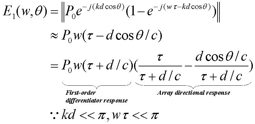
여기서, 2 개의 마이크로폰 간의 간격 d는 음원의 파장의 절반보다 작다는 협대역 가정(narrowband assumption)을 사용하였다. 협대역 가정은 마이크로폰 어레이의 배치에 따라 공간상의 앨리에이싱(spatial aliasing)이 발생하지 않음을 가정하는 것으로 음원이 왜곡되는 경우를 배제하기 위함이다. 수학식 1에서 c는 공기 중 음파의 속도인 340m/sec이고, P0는 진폭(amplitude), w는 각 주파수(angular frequency), τ는 적응 지연항(adaptive delay), θ는 음원으로부터의 신호가 마이크로폰에 입력되는 입사각을 나타낸다. 그리고, k는 파수(wave number)이고, k=w/c로 나타낼 수 있다.Here, we use the narrowband assumption that the spacing d between the two microphones is less than half the wavelength of the source. The narrowband assumption is based on the assumption that spatial aliasing does not occur in the space according to the arrangement of the microphone arrays, so that the case where the sound sources are distorted is excluded. In Equation (1), c is the velocity of the sound wave in air of 340 m / sec, P 0 is the amplitude, w is the angular frequency, τ is the adaptive delay, Represents the incident angle to be input to the microphone. K is a wave number, and k = w / c.
수학식 1을 참조하면, 마이크로폰 어레이에 입력된 음원 신호의 음압장은 변수 w와 θ에 의한 식으로 표현되어 있으며, 이러한 음압장은 수학식 1의 두 번째 식에서 보듯이 1차 차분 반응(first-order differentiator response)과 어레이 지향성 응답(array directional response)의 곱으로 표현되어 있다. 이 중에서 1차 차분 반응은 주파수 w에 의해 영향을 받는 항으로서 저대역 통과 필터(lowpass filter)에 의해 쉽게 제거될 수 있다. 즉, 저대역 통과 필터에서의 1/w의 주파수 응답(frequency response)을 통해 상기 수학식 1의 1차 차분 반응은 제거될 수 있다. 이러한 저대역 통과 필터는 도 4의 LPF(220)로서 도시되어 있으며, 수학식 1에서 주파수의 변화를 억제함으로써 음압장이 어레이 지향성 반응에 선형성을 갖도록 유도하는 역할을 한다.Referring to
한편, 저대역 통과 필터에 의해 필터링된 음원 신호는 협대역 가정의 지역 내에서는 주파수에 독립적이므로, 이 경우의 마이크로폰 어레이의 지향성 감도(지향성 응답(directional response)으로도 호칭될 수 있다)는 다음 수학식 3과 같이 적응 지연항 τ 또는 마이크로폰 간의 간격 d와 같은 특정 인자(parameter)들의 조합으로 정의될 수 있다. 다음 수학식 2 및 수학식 3을 참조하면, 마이크로폰 어레이의 지향성 감도는 적응 지연항 τ 또는 마이크로폰 간의 간격 d을 변화시킴으로써 조절될 수 있음을 알 수 있다.On the other hand, since the excitation signal filtered by the low-pass filter is frequency-independent in the region of the narrowband assumption, the directional sensitivity of the microphone array in this case (which may also be referred to as a directional response) Can be defined as a combination of specific parameters such as the adaptive delay term τ or the spacing d between the microphones as shown in equation (3). Referring to the following equations (2) and (3), it can be seen that the directional sensitivity of the microphone array can be adjusted by changing the adaptive delay term? Or the distance d between the microphones.

수학식 2에서 변수 알파(α)는 다음의 수학식 3과 같다.In Equation (2), the variable alpha (alpha) is expressed by Equation (3).

상기된 바와 같은 마이크로폰 어레이에 입력된 수학식 1의 음압장을 갖는 음원 신호의 성질을 이용하여, 억제 폭 조절부(200)의 지연부(210), 저대역 통과 필터(220) 및 감산부(230)는 다음과 같이 줌 제어부(500)의 줌 제어 신호와 연동하여 소정 거리에 위치한 목표 음원에 대한 마이크로폰 어레이의 지향성 감도를 억제할 수 있다. The
즉, 지연부(210)는 마이크로폰 어레이에 입력된 수학식 1의 음압장을 갖는 음원 신호에 대해 측면 마이크로폰 신호 X2(t)를 줌 제어부(500)의 줌 제어 신호에 대응하는 적응 지연항(adaptive delay) τ만큼 지연하고, 감산부(230)는 지연부(210)에 의해 지연된 측면 마이크로폰 신호 X2(t)로부터 전방 마이크로폰 신호 X1(t)를 감산하고, 저대역 통과 필터(220)는 감산부(230)에 의해 감산된 결과를 저대역 통과 필터링함으로써 음원 신호의 특성에 따라 변화하는 진폭 성분과 주파수 성분이 포함된 1차 차분 반응(first-order differentiator response)을 고정한다.That is, the
상기된 바와 같이, 수학식 1의 성분들 중 음원 신호의 특성에 따라 변화하는 진폭 성분과 주파수 성분이 포함된 1차 차분 반응(first-order differentiator response)을 고정시킨다면, 수학식 1은 적응 지연항 τ와 마이크로폰들 간의 거리 d에 의해 결정되는 선형성을 갖게 되기 때문에 적응 지연항 τ와 마이크로폰들 간의 거리 d를 조절함으로써 소정 거리에 위치한 목표 음원 신호가 억제된 수학식 1, 즉 음압장이 형성되도록 할 수 있다. 일반적으로, 마이크로폰들 간의 거리 d는 고정된 값이기 때문에 사운드 줌 신호에 대응하여 적응 지연항 τ가 조절될 수 있다. 즉, 억제 폭 조절부(200)는 상기된 바와 같은 지연부(210), 저대역 통과 필터(220) 및 감산부(230)의 동작에 의해 사운드 줌 장치로부터 소정 거리에 위치한 목표 음원에 대한 마이크로폰 어레이의 지향성 감도를 억제할 수 있다. As described above, if a first-order differentiator response including an amplitude component and a frequency component varying according to the characteristics of a sound source signal among the components of
한편, 미국 등록 특허(Zoom microphone device, Takashi Kawamura, US 6,931,138)에는 지향 특성을 조절하여 줌 렌즈가 원거리를 촬영하려는 경우(telescopic), 전방의 음원만을 받아들이고, 잡음 제거량을 줌 렌즈 제어부와 연동하는 장치가 개시되어 있다. 이 특허에서 잡음 제거 기능은 주파수 영역에서 위너 필터(wiener filter)로 구현되고, 억압비(suppression ratio), 플로어링 상수(flooring constants)를 줌과 연동하여 조절하는데, 원거리 촬영시 근거리 배경 잡음의 영향을 줄이기 위해 잡음 억제(noise suppression)를 증가시키고, 원거리 음성의 볼륨을 키운다. 그러나, 이러한 방식은 원거리 음원의 신호 대 잡음비가 낮은 경우, 원거리 음원 신호를 잡음으로 오인하여 제거할 가능성이 있고, 오히려 근거리 음원만이 부각될 우려가 있다. 신호 대 잡음비란 정상적으로 운용하는 상태의 표준 신호(nominal level)와 비교하였을 때의 잡음의 정도를 의미한다. 즉, 원거리 촬영시 근거리 음원을 제거할 수 없고, 위너 필터의 잡음 특성상 시간에 따라 변하지 않는(time-invariant) 정상 상태 잡음(stationary noise)만 제거할 수 있어, 음악이나 웅성거리는 배블 잡음(babble noise)과 같은 실생활의 비정상 상태(non-stationary) 신호에 대해서는 성능이 떨어지는 문제점이 있다. 왜냐하면, 단지 위너 필터의 잡음 제거량을 줌 렌즈 제어부에만 연동시킴으로써 정상 상태(stationary)의 잡음 제거에만 적용 가능하기 때문이다.Meanwhile, a Zoom microphone device (Takashi Kawamura, US Pat. No. 6,931,138) discloses a zoom lens system in which a zoom lens is telescopic by controlling a directivity characteristic, and only a sound source in front is received and a noise elimination amount is interlocked with a zoom lens controller . In this patent, the noise cancellation function is implemented by a wiener filter in the frequency domain, and the suppression ratio and the flooring constants are adjusted in conjunction with the zoom, and the effect of the near background noise To reduce noise suppression (noise suppression) and increase the volume of distant voice. However, when the signal-to-noise ratio of the remote source is low, such a scheme may possibly remove the distant source signal by mistaking it for noise, and there is a possibility that only the near source is highlighted. The signal-to-noise ratio is the degree of noise compared to the nominal level of normal operation. That is, it is not possible to remove the near-end sound source during the long distance photographing, and it is possible to remove only the stationary noise which is time-invariant in time due to the noise characteristic of the Wiener filter. Thus, the music or male- ), There is a problem that performance is degraded for a non-stationary signal in real life. This is because only the noise removal amount of the Wiener filter can be applied only to stationary noise cancellation by interlocking only with the zoom lens control part.
상기 미국 등록 특허와는 달리, 본 실시예의 신호 추출부에서는 목표 음원을 추출하기 위해 소정의 잡음 제거(noise cancelling) 기술 중 하나인 적응 잡음 제거 기술(adaptive noise cancelling, 이하 ANC)을 이용할 수 있다. 도 4에서는 ANC로서 FIR 필터(finite impulse response filter) W(310)가 사용되었다. 여기서 ANC는 적응 신호 처리(adaptive signal processing)의 일종으로서, 적응 신호 처리는 환경이 시간에 따라 변하고 대상 신호가 잘 알려져 있지 않은 경우 원본 신호를 필터링 처리한 결과 신호를 다시 오차를 최소화시키는 적응 알고리즘을 통해 필터에 반영함으로써 대상 신호에 근접하게 접근시키는 일종의 피드백(feedback) 시스템이며, 이러한 적응 신호 처리를 신호 특성을 이용한 잡음 제거에 활용한 것이 바로 ANC이다.Unlike the US patent, the signal extracting unit of this embodiment can use adaptive noise cancellation (ANC), which is one of predetermined noise canceling techniques, to extract a target sound source. In FIG. 4, a finite impulse
ANC는 실시간으로 신호 특성이 변화하는 비정상 상태에서의 시간에 따른 변화를 계속해서 피드백함으로써 FIR 필터를 학습(learning)시키고, 학습된 FIR 필터를 통해 실생활에서 발생하는 시간에 따라 변화하는(time-varying) 배경 잡음을 제거할 수 있게 된다. 즉, ANC는 목표 음원과 배경 잡음의 통계적 특성이 다른 점을 이용하여 잡음 발생원으로부터 마이크로폰까지의 전달 함수(transfer function)를 자동으로 모델링하게 된다. FIR 필터의 학습은 일반적인 LMS(least mean squre) 방식이나 NLMS(nomalized least mean square), RMS(recursive mean square) 방식의 적응 학습 기술을 이용할 수 있다. 이러한 ANC와 필터의 학습 방식들은 본 발명이 속하는 기술 분야에서 통상의 지식을 가진 자가 용이하게 파악할 수 있는 내용이므로 자세한 설명은 생략한다.The ANC can learn the FIR filter by continuously feedbacking the change with time in the abnormal state in which the signal characteristic changes in real time, and the time-varying ) Background noise can be removed. That is, the ANC automatically models the transfer function from the noise source to the microphone using the difference between the statistical characteristics of the target sound source and the background noise. Learning of the FIR filter can utilize a general least mean squares (LMS) method, an adaptive learning technique of a nomalized least mean square (NLMS), and a recursive mean square (RMS) method. The learning methods of the ANC and the filter are easily understandable to those skilled in the art, so a detailed description thereof will be omitted.
이하에서는 이러한 ANC의 동작을 수학식 4 내지 수학식 6을 통해 보다 상세히 설명한다.Hereinafter, the operation of the ANC will be described in more detail with reference to Equations (4) to (6).

수학식 4에서 H(z)는 룸 임펄스 응답(room impluse response)으로 원본 신호와 마이크로폰간 공간상의 전달 함수(transfer function)이다. X1(z)와 X2(z)는 최초에 마이크로폰 어레이로 입력되는 입력 신호를 의미하는 것으로, 각각의 입력 신호는 원거리 음원 신호인 SFar(z)와 근거리 음원 신호인 SNear(z)가 공간상에서 선형 필터 결합으로 이루어진다는 것을 가정한다.In Equation (4), H (z) is a room impulse response, which is a transfer function on the space between the original signal and the microphone. X 1 (z) and X 2 (z) is S Near the as referring to the input signal input to the microphone array to the first, each of the input signals S Far (z) and near the sound source signal is a remote sound source signal (z) ≪ / RTI > is made up of a linear filter combination in space.
도 4에서 전방 마이크로폰으로 입력된 음원 신호 X1(t)는 그대로 억제 폭 조절부(200)의 출력 신호 Y1(t)이 된다고 하였고, 측면 마이크로폰으로 입력된 음원 신호 X2(t)는 목표 음원만 제거된 출력 신호 Y2(t)가 된다고 하였다. 이러한 억제 폭 조절부(200)의 출력 신호 Y1(t), Y2(t)를 상기 수학식 4를 참조하여 정리하면 다음의 수학식 5와 같다.4, it is assumed that the sound source signal X 1 (t) input through the front microphone becomes the output signal Y 1 (t) of the

다시 도 4로 돌아와서 신호 추출부(300)를 살펴보면, 신호 추출부(300)는 FIR 필터(310), 고정 지연부(320), 지연 필터(330) 및 2 개의 감산부(340, 350)로 구성된다. FIR 필터(310)는 억제 폭 조절부(200)에 의해 목표 음원이 제거된 신호 Y2(t)를 잡음으로 추정하고, 고정 지연부(320)는 1차 차분 마이크로폰에서의 계산 지연(latency)을 보상하며, 감산부(340)는 상기 FIR 필터(310)에서 추정된 잡음 신호로 고정 지연부(320)에서 지연된 음원 신호 Y1(t)를 감산함으로써 목표 음원에 해당하는 음원 신호 Z1(t)을 추출한다. ANC는 이렇게 추출된 결과물인 음원 신호 Z1(t)를 다시 FIR 필터(310)에 피드백함으로써 목표 음원에 근접하게 접근시킨다. 따라서, ANC는 시간에 따라 신호 특성이 변화하는 비정상 상태에서 잡음 제거를 효과적으로 수행할 수 있다. 여기서, 고정 지연항(fixed delay) T(320)는 1차 차분 마이크로폰에서의 계산 지연(latency)을 보상하고, ANC 구조에서 캐주얼 FIR 필터(casual FIR filter)를 사용하기 위해 도입되었으며, 시스템의 계산 용량에 맞추어 미리 설정해(pre-setting) 두어야 한다.4, the
이러한 과정을 상기 수학식 5를 참고하여 기술하면 다음의 수학식 6과 같다.This process will be described with reference to Equation (5) below.

수학식 6은 음원 신호 Y1(t)과 FIR 필터(310) W를 거친 음원 신호 Y2(t)를 감산하는 것을 수식으로 표현한 것이다. 수학식 6에서 FIR 필터(310) W를 적응 학습 기술을 이용하여 조절하면, 즉 (H21(z)-W(z)H22(z)) 값을 0으로 만들면 근거리 음원의 신호를 제거할 수 있음을 보여주고 있다. 이는 원거리 음원을 취득하려고 할 경우 근거리의 배경 간섭음을 잡음으로 추정하여 제거할 수 있음을 의미한다.Equation (6) is a formula expressing subtraction of the sound source signal Y 1 (t) and the sound source signal Y 2 (t) passing through the
마지막으로 전방 마이크로폰에 입력된 음원 신호 X1(t)을 지연부(330)를 통해 필터링시킨 다음, 감산부(350)를 통해 목표 음원에 해당하는 신호 Z1(t)으로 감산하면 목표 음원이 제거된 신호 Z2(t)를 추출할 수 있다.Finally, the sound source signal X 1 (t) input to the front microphone is filtered through the
이러한 과정을 상기 수학식 6을 참고하여 기술하면 다음의 수학식 7과 같다.This process will be described with reference to Equation (6) below.

이상에서 설명한 바와 같이, 도 4의 실시예에서는 목표 음원 신호에 대해 직접 지향성 감도를 조절하여 취득하는 것이 아니라, 우선 지향성 감도를 억제하는 억제 폭의 패턴을 조절함으로써 목표 음원이 제거된 신호를 생성한다. 그 다음으로 목표 음원이 제거된 신호로부터 잡음 제거 기술을 이용하여 목표 음원이 제거된 신호를 잡음으로 추정한 후, 이를 전체 신호에서 감산하는 방법을 통해 목표 음원에 해당하는 신호를 생성하게 된다.As described above, in the embodiment of FIG. 4, the target sound source is removed by adjusting the pattern of the suppression width for suppressing the directivity sensitivity, instead of directly acquiring the directivity sensitivity by adjusting the directivity sensitivity for the target sound source signal . Next, a signal corresponding to the target sound source is generated by estimating a signal from which the target sound source has been removed using a noise cancellation technique from the signal from which the target sound source is removed, and subtracting the signal from the total signal.
한편, 도 2에서 설명한 바와 같이 이상과 같은 과정을 통해 신호 추출부에서 이미 사용자가 원하는 목표 음원 신호가 추출되었지만, 줌 제어 신호에 따라 보다 정교하게 목표 음원 신호를 합성하기 위해 이하의 실시예에서는 이러한 신호의 합성 과정을 설명한다.2, the target sound source signal desired by the user has already been extracted by the signal extracting unit. However, in order to more precisely synthesize the target sound source signal according to the zoom control signal, in the following embodiments, The signal synthesis process will be described.
도 5는 본 발명의 일 실시예에 따른 사운드 줌 장치에서 신호 합성부(400)를 도시한 도면으로서, 신호 합성부(400)는 신호 추출부(미도시)로부터 추출된 원거리 음원 신호 Z1(z)와 근거리 음원 신호 Z2(z)에 기초하여 줌 제어부의 제어 신호에 따라 최종 출력 신호를 합성한다. 이러한 신호 합성 과정은 원거리 음원 신호와 근거리 음원 신호를 선형적으로 결합시키고, 사운드 줌 제어 신호에 따라 양자의 신호 강도를 배타적으로 조절함으로써 출력 신호를 합성할 수 있다. 최종 출력 신호를 표현하면 다음의 수학식 8과 같다.5 is a block diagram illustrating a

여기서 β는 2 개의 음원 신호를 결합함에 있어서 배타적인 가중치를 표현한 변수로서 0에서 1 사이의 값을 갖는다. 즉, 줌 제어부(500)의 제어 신호에 따라, 만약 목표 신호가 근거리 음원 신호인 경우 β를 0에 근접시킴으로써 출력 신호의 대부분을 근거리 음원 신호인 Z2(z)만으로 구성되게 하면 되고, 반대로 목표 신호가 원거리 음원 신호인 경우 β를 1에 근접시킴으로써 출력 신호의 대부분을 원거리 음원 신호인 Z1(z)만으로 구성되게 하면 된다.Here, β is a variable representing an exclusive weight in combining two sound source signals and has a value between 0 and 1. That is, according to the control signal of the
도 6은 본 발명의 일 실시예에 따른 사운드 줌 장치에서 억제 폭 조절 인자에 따른 억제 폭 조절 성능을 도시한 폴라 패턴(polar pattern)으로서, 수학식 2의 지향성 응답을 각도(θ) 및 변수 알파(α)에 따라 도시하였다. 일반적으로 마이크로폰 등의 음향 기기가 갖는 지향성을 나타내기 위해 마이크로폰을 중심으로 하여 마이크로폰의 전방을 0도로 정하고 마이크로폰을 둘러싼 주위의 각도에 따라 0도에서 360도까지의 마이크로폰의 감도를 차트(chart)로 표현하는데 이러한 차트를 폴라 패턴(polar pattern)이라고 한다. 도 6은 1차 차분 마이크로폰 구조와 2차 차분 마이크로폰 구조의 경우에 각각 억제 폭 제어가 매개변수 알파 하나로 쉽게 이루어 질 수 있음을 보여준다. 수학식 2 및 수학식 3에서 설명한 바와 같이 이러한 알파 값은 음원의 억제 폭 제어 인자들 중 하나로서 줌 제어부의 제어 신호와 연동되어 조절된다.6 is a polar pattern showing the suppression width control performance according to the suppression width control factor in the sound zoom apparatus according to the embodiment of the present invention, in which the directional response of the equation (2) (?). Generally, in order to show the directivity of an acoustic device such as a microphone, a microphone is set at a front of 0 degree and a sensitivity of a microphone from 0 to 360 degrees is plotted according to the angle around the microphone These charts are called polar patterns. FIG. 6 shows that, in the case of the first-order differential microphone structure and the second-order differential microphone structure, the suppression width control can be easily performed with one parameter alpha. As described in Equation (2) and Equation (3), this alpha value is adjusted in conjunction with the control signal of the zoom control unit as one of the suppression width control factors of the sound source.
도 6에서 원거리 목표 음원이 폴라 패턴의 0도 방향에서 제거되고, 알파 값의 변화에 따라 억제 폭의 패턴이 변화함으로써 배경 잡음을 감소시키고 있음을 보여주고 있다. 도 6의 상측 폴라 패턴은 1차 차분 마이크로폰 구조에서의 억제 폭 변화를 도시한 것으로 알파 값의 변화에 따라 611에서 612로 억제 폭이 변화하고 있다. 또한, 도 6의 하측 폴라 패턴은 2차 차분 마이크로폰 구조에서의 억제 폭 변화를 도시한 것으로 마찬가지로 알파 값의 변화에 따라 621에서 622로 억제 폭이 변화하고 있다.FIG. 6 shows that the far-point target sound source is removed in the 0 degree direction of the polar pattern, and the background noise is reduced by changing the pattern of the suppression width according to the change of the alpha value. The upper polar pattern of FIG. 6 shows the width of the suppression width in the first-order differential microphone structure, and the suppression width is changed from 611 to 612 according to the change of the alpha value. The lower polar pattern of FIG. 6 shows the width of the suppression width in the second-order differential microphone structure, and the suppression width is changed from 621 to 622 according to the change of the alpha value.
한편, 도 6의 폴라 패턴의 0도 방향의 억제 폭과는 정반대의 180도 방향으로 둥근 모양의 지향 폭이 표시되어 있다. 이러한 지향 폭 역시 알파 값의 변화에 따라 변화하고 있는데, 억제 폭 변화량과 비교할 때 상대적으로 작은 폭의 변화를 보이고 있음을 알 수 있다. 즉, 도 6은 앞서 언급한 바와 같이 억제 폭에 비해 지향 폭의 조절이 용이하지 않으며, 이를 반대로 생각하면 억제 폭 조절이 지향 폭 조절보다 더 효과가 좋다는 것을 실험적으로 보여주고 있다.On the other hand, a directivity width of a circular shape in the 180-degree direction opposite to the suppression width in the 0-degree direction of the polar pattern in Fig. 6 is displayed. This directional width also changes with the change of the alpha value, and it can be seen that the width of change is relatively small as compared with the amount of change of the suppression width. That is, as shown in FIG. 6, it is not easy to adjust the directivity width as compared to the suppression width. Conversely, it is experimentally shown that the suppression width control is more effective than the directivity width control.
이상에서 본 발명에 대하여 그 바람직한 실시예들을 중심으로 살펴보았다. 본 발명에 속하는 기술 분야에서 통상의 지식을 가진 자는 본 발명이 본 발명의 본질적인 특성에서 벗어나지 않는 범위에서 변형된 형태로 구현될 수 있음을 이해할 수 있을 것이다. 그러므로 개시된 실시예들은 한정적인 관점이 아니라 설명적인 관 점에서 고려되어야 한다. 본 발명의 범위는 전술한 설명이 아니라 특허청구범위에 나타나 있으며, 그와 동등한 범위 내에 있는 모든 차이점은 본 발명에 포함된 것으로 해석되어야 할 것이다.The preferred embodiments of the present invention have been described above. It will be understood by those skilled in the art that various changes in form and details may be made therein without departing from the spirit and scope of the invention as defined by the appended claims. The disclosed embodiments are therefore to be considered in an illustrative rather than a restrictive sense. The scope of the present invention is defined by the appended claims rather than by the foregoing description, and all differences within the scope of equivalents thereof should be construed as being included in the present invention.
도 1a 내지 도 1b는 본 발명이 해결하려는 문제의 발생 상황을 도시한 도면이다.1A to 1B are diagrams showing the occurrence situation of a problem to be solved by the present invention.
도 1c는 본 발명의 일 실시예에 따른 사운드 줌 기능을 구현하기 위해 디지털 캠코더에 2 개의 마이크로폰들을 배치한 도면이다.FIG. 1C is a diagram showing a configuration in which two microphones are arranged in a digital camcorder to implement a sound zoom function according to an embodiment of the present invention.
도 2는 본 발명의 일 실시예에 따른 사운드 줌 장치의 기능별 블럭도이다.2 is a functional block diagram of a sound zoom apparatus according to an embodiment of the present invention.
도 3은 본 발명의 일 실시예에 따른 사운드 줌 장치의 각 구성에 입출력 신호를 추가하여 도시한 블럭도이다.3 is a block diagram illustrating input / output signals added to each configuration of the sound zoom apparatus according to an embodiment of the present invention.
도 4는 본 발명의 일 실시예에 따른 사운드 줌 장치에서 줌 제어부와 연동된 억제 폭 조절부와 신호 추출부를 도시한 도면이다.FIG. 4 is a block diagram illustrating a suppression control unit and a signal extraction unit interlocked with a zoom control unit in a sound zoom apparatus according to an exemplary embodiment of the present invention. Referring to FIG.
도 5는 본 발명의 일 실시예에 따른 사운드 줌 장치에서 신호 합성부를 도시한 도면이다.5 is a diagram illustrating a signal synthesizing unit in a sound zooming apparatus according to an embodiment of the present invention.
도 6은 본 발명의 일 실시예에 따른 사운드 줌 장치에서 억제 폭 조절 인자에 따른 억제 폭 조절 성능을 도시한 폴라 패턴(polar pattern)이다.FIG. 6 is a polar pattern illustrating the suppression width control performance according to the suppression width adjustment factor in the sound zoom apparatus according to an embodiment of the present invention.
Claims (13)
Priority Applications (3)
| Application Number | Priority Date | Filing Date | Title |
|---|---|---|---|
| KR1020070089960A KR101409169B1 (en) | 2007-09-05 | 2007-09-05 | Sound zooming method and apparatus by controlling null widt |
| US12/010,087 US8290177B2 (en) | 2007-09-05 | 2008-01-18 | Sound zoom method, medium, and apparatus |
| US13/627,306 US20130022217A1 (en) | 2007-09-05 | 2012-09-26 | Sound zoom method, medium, and apparatus |
Applications Claiming Priority (1)
| Application Number | Priority Date | Filing Date | Title |
|---|---|---|---|
| KR1020070089960A KR101409169B1 (en) | 2007-09-05 | 2007-09-05 | Sound zooming method and apparatus by controlling null widt |
Publications (2)
| Publication Number | Publication Date |
|---|---|
| KR20090024963A KR20090024963A (en) | 2009-03-10 |
| KR101409169B1 true KR101409169B1 (en) | 2014-06-19 |
Family
ID=40407516
Family Applications (1)
| Application Number | Title | Priority Date | Filing Date |
|---|---|---|---|
| KR1020070089960A KR101409169B1 (en) | 2007-09-05 | 2007-09-05 | Sound zooming method and apparatus by controlling null widt |
Country Status (2)
| Country | Link |
|---|---|
| US (2) | US8290177B2 (en) |
| KR (1) | KR101409169B1 (en) |
Families Citing this family (75)
| Publication number | Priority date | Publication date | Assignee | Title |
|---|---|---|---|---|
| US9210503B2 (en) * | 2009-12-02 | 2015-12-08 | Audience, Inc. | Audio zoom |
| US9838784B2 (en) | 2009-12-02 | 2017-12-05 | Knowles Electronics, Llc | Directional audio capture |
| CN102137318B (en) * | 2010-01-22 | 2014-08-20 | 华为终端有限公司 | Method and device for controlling adapterization |
| US8913757B2 (en) | 2010-02-05 | 2014-12-16 | Qnx Software Systems Limited | Enhanced spatialization system with satellite device |
| US20110200205A1 (en) * | 2010-02-17 | 2011-08-18 | Panasonic Corporation | Sound pickup apparatus, portable communication apparatus, and image pickup apparatus |
| US8798290B1 (en) | 2010-04-21 | 2014-08-05 | Audience, Inc. | Systems and methods for adaptive signal equalization |
| US9558755B1 (en) | 2010-05-20 | 2017-01-31 | Knowles Electronics, Llc | Noise suppression assisted automatic speech recognition |
| US8908877B2 (en) | 2010-12-03 | 2014-12-09 | Cirrus Logic, Inc. | Ear-coupling detection and adjustment of adaptive response in noise-canceling in personal audio devices |
| JP5937611B2 (en) | 2010-12-03 | 2016-06-22 | シラス ロジック、インコーポレイテッド | Monitoring and control of an adaptive noise canceller in personal audio devices |
| US8942382B2 (en) * | 2011-03-22 | 2015-01-27 | Mh Acoustics Llc | Dynamic beamformer processing for acoustic echo cancellation in systems with high acoustic coupling |
| JP2012238964A (en) * | 2011-05-10 | 2012-12-06 | Funai Electric Co Ltd | Sound separating device, and camera unit with it |
| US8948407B2 (en) | 2011-06-03 | 2015-02-03 | Cirrus Logic, Inc. | Bandlimiting anti-noise in personal audio devices having adaptive noise cancellation (ANC) |
| US8958571B2 (en) * | 2011-06-03 | 2015-02-17 | Cirrus Logic, Inc. | MIC covering detection in personal audio devices |
| US9214150B2 (en) | 2011-06-03 | 2015-12-15 | Cirrus Logic, Inc. | Continuous adaptation of secondary path adaptive response in noise-canceling personal audio devices |
| US9318094B2 (en) | 2011-06-03 | 2016-04-19 | Cirrus Logic, Inc. | Adaptive noise canceling architecture for a personal audio device |
| US9824677B2 (en) | 2011-06-03 | 2017-11-21 | Cirrus Logic, Inc. | Bandlimiting anti-noise in personal audio devices having adaptive noise cancellation (ANC) |
| GB2493801B (en) * | 2011-08-18 | 2014-05-14 | Ibm | Improved audio quality in teleconferencing |
| JP5817366B2 (en) * | 2011-09-12 | 2015-11-18 | 沖電気工業株式会社 | Audio signal processing apparatus, method and program |
| US9325821B1 (en) * | 2011-09-30 | 2016-04-26 | Cirrus Logic, Inc. | Sidetone management in an adaptive noise canceling (ANC) system including secondary path modeling |
| US8879761B2 (en) | 2011-11-22 | 2014-11-04 | Apple Inc. | Orientation-based audio |
| US8903108B2 (en) * | 2011-12-06 | 2014-12-02 | Apple Inc. | Near-field null and beamforming |
| US9020163B2 (en) | 2011-12-06 | 2015-04-28 | Apple Inc. | Near-field null and beamforming |
| US9142205B2 (en) | 2012-04-26 | 2015-09-22 | Cirrus Logic, Inc. | Leakage-modeling adaptive noise canceling for earspeakers |
| US9014387B2 (en) | 2012-04-26 | 2015-04-21 | Cirrus Logic, Inc. | Coordinated control of adaptive noise cancellation (ANC) among earspeaker channels |
| US9123321B2 (en) | 2012-05-10 | 2015-09-01 | Cirrus Logic, Inc. | Sequenced adaptation of anti-noise generator response and secondary path response in an adaptive noise canceling system |
| US9318090B2 (en) | 2012-05-10 | 2016-04-19 | Cirrus Logic, Inc. | Downlink tone detection and adaptation of a secondary path response model in an adaptive noise canceling system |
| US9319781B2 (en) | 2012-05-10 | 2016-04-19 | Cirrus Logic, Inc. | Frequency and direction-dependent ambient sound handling in personal audio devices having adaptive noise cancellation (ANC) |
| US9082387B2 (en) | 2012-05-10 | 2015-07-14 | Cirrus Logic, Inc. | Noise burst adaptation of secondary path adaptive response in noise-canceling personal audio devices |
| US9183844B2 (en) * | 2012-05-22 | 2015-11-10 | Harris Corporation | Near-field noise cancellation |
| US9258644B2 (en) | 2012-07-27 | 2016-02-09 | Nokia Technologies Oy | Method and apparatus for microphone beamforming |
| US9532139B1 (en) | 2012-09-14 | 2016-12-27 | Cirrus Logic, Inc. | Dual-microphone frequency amplitude response self-calibration |
| CN103856877B (en) * | 2012-11-28 | 2017-11-28 | 联想(北京)有限公司 | A kind of acoustic control information detecting method and electronic equipment |
| JP6226301B2 (en) * | 2012-12-21 | 2017-11-08 | パナソニックIpマネジメント株式会社 | Directional microphone device, acoustic signal processing method and program |
| US9107010B2 (en) | 2013-02-08 | 2015-08-11 | Cirrus Logic, Inc. | Ambient noise root mean square (RMS) detector |
| US9369798B1 (en) | 2013-03-12 | 2016-06-14 | Cirrus Logic, Inc. | Internal dynamic range control in an adaptive noise cancellation (ANC) system |
| US9215749B2 (en) | 2013-03-14 | 2015-12-15 | Cirrus Logic, Inc. | Reducing an acoustic intensity vector with adaptive noise cancellation with two error microphones |
| US9414150B2 (en) | 2013-03-14 | 2016-08-09 | Cirrus Logic, Inc. | Low-latency multi-driver adaptive noise canceling (ANC) system for a personal audio device |
| US9208771B2 (en) | 2013-03-15 | 2015-12-08 | Cirrus Logic, Inc. | Ambient noise-based adaptation of secondary path adaptive response in noise-canceling personal audio devices |
| US9324311B1 (en) | 2013-03-15 | 2016-04-26 | Cirrus Logic, Inc. | Robust adaptive noise canceling (ANC) in a personal audio device |
| US9467776B2 (en) | 2013-03-15 | 2016-10-11 | Cirrus Logic, Inc. | Monitoring of speaker impedance to detect pressure applied between mobile device and ear |
| US9635480B2 (en) | 2013-03-15 | 2017-04-25 | Cirrus Logic, Inc. | Speaker impedance monitoring |
| US10206032B2 (en) | 2013-04-10 | 2019-02-12 | Cirrus Logic, Inc. | Systems and methods for multi-mode adaptive noise cancellation for audio headsets |
| US9462376B2 (en) | 2013-04-16 | 2016-10-04 | Cirrus Logic, Inc. | Systems and methods for hybrid adaptive noise cancellation |
| US9478210B2 (en) | 2013-04-17 | 2016-10-25 | Cirrus Logic, Inc. | Systems and methods for hybrid adaptive noise cancellation |
| US9460701B2 (en) | 2013-04-17 | 2016-10-04 | Cirrus Logic, Inc. | Systems and methods for adaptive noise cancellation by biasing anti-noise level |
| US9578432B1 (en) | 2013-04-24 | 2017-02-21 | Cirrus Logic, Inc. | Metric and tool to evaluate secondary path design in adaptive noise cancellation systems |
| US9264808B2 (en) | 2013-06-14 | 2016-02-16 | Cirrus Logic, Inc. | Systems and methods for detection and cancellation of narrow-band noise |
| US9536540B2 (en) | 2013-07-19 | 2017-01-03 | Knowles Electronics, Llc | Speech signal separation and synthesis based on auditory scene analysis and speech modeling |
| US9392364B1 (en) | 2013-08-15 | 2016-07-12 | Cirrus Logic, Inc. | Virtual microphone for adaptive noise cancellation in personal audio devices |
| US9666176B2 (en) | 2013-09-13 | 2017-05-30 | Cirrus Logic, Inc. | Systems and methods for adaptive noise cancellation by adaptively shaping internal white noise to train a secondary path |
| US9620101B1 (en) | 2013-10-08 | 2017-04-11 | Cirrus Logic, Inc. | Systems and methods for maintaining playback fidelity in an audio system with adaptive noise cancellation |
| KR102186307B1 (en) * | 2013-11-08 | 2020-12-03 | 한양대학교 산학협력단 | Beam-forming system and method for binaural hearing support device |
| US9704472B2 (en) | 2013-12-10 | 2017-07-11 | Cirrus Logic, Inc. | Systems and methods for sharing secondary path information between audio channels in an adaptive noise cancellation system |
| US10219071B2 (en) | 2013-12-10 | 2019-02-26 | Cirrus Logic, Inc. | Systems and methods for bandlimiting anti-noise in personal audio devices having adaptive noise cancellation |
| US10382864B2 (en) | 2013-12-10 | 2019-08-13 | Cirrus Logic, Inc. | Systems and methods for providing adaptive playback equalization in an audio device |
| US9369557B2 (en) | 2014-03-05 | 2016-06-14 | Cirrus Logic, Inc. | Frequency-dependent sidetone calibration |
| US9479860B2 (en) | 2014-03-07 | 2016-10-25 | Cirrus Logic, Inc. | Systems and methods for enhancing performance of audio transducer based on detection of transducer status |
| US9648410B1 (en) | 2014-03-12 | 2017-05-09 | Cirrus Logic, Inc. | Control of audio output of headphone earbuds based on the environment around the headphone earbuds |
| US9319784B2 (en) | 2014-04-14 | 2016-04-19 | Cirrus Logic, Inc. | Frequency-shaped noise-based adaptation of secondary path adaptive response in noise-canceling personal audio devices |
| US9609416B2 (en) | 2014-06-09 | 2017-03-28 | Cirrus Logic, Inc. | Headphone responsive to optical signaling |
| US10181315B2 (en) | 2014-06-13 | 2019-01-15 | Cirrus Logic, Inc. | Systems and methods for selectively enabling and disabling adaptation of an adaptive noise cancellation system |
| JP6460676B2 (en) * | 2014-08-05 | 2019-01-30 | キヤノン株式会社 | Signal processing apparatus and signal processing method |
| US9478212B1 (en) | 2014-09-03 | 2016-10-25 | Cirrus Logic, Inc. | Systems and methods for use of adaptive secondary path estimate to control equalization in an audio device |
| US9978388B2 (en) | 2014-09-12 | 2018-05-22 | Knowles Electronics, Llc | Systems and methods for restoration of speech components |
| KR102174850B1 (en) * | 2014-10-31 | 2020-11-05 | 한화테크윈 주식회사 | Environment adaptation type beam forming apparatus for audio |
| US9552805B2 (en) | 2014-12-19 | 2017-01-24 | Cirrus Logic, Inc. | Systems and methods for performance and stability control for feedback adaptive noise cancellation |
| US9668048B2 (en) | 2015-01-30 | 2017-05-30 | Knowles Electronics, Llc | Contextual switching of microphones |
| KR20180044324A (en) | 2015-08-20 | 2018-05-02 | 시러스 로직 인터내셔널 세미컨덕터 리미티드 | A feedback adaptive noise cancellation (ANC) controller and a method having a feedback response partially provided by a fixed response filter |
| US9578415B1 (en) | 2015-08-21 | 2017-02-21 | Cirrus Logic, Inc. | Hybrid adaptive noise cancellation system with filtered error microphone signal |
| US10013966B2 (en) | 2016-03-15 | 2018-07-03 | Cirrus Logic, Inc. | Systems and methods for adaptive active noise cancellation for multiple-driver personal audio device |
| US9820042B1 (en) | 2016-05-02 | 2017-11-14 | Knowles Electronics, Llc | Stereo separation and directional suppression with omni-directional microphones |
| CN106782596A (en) * | 2016-11-18 | 2017-05-31 | 深圳市行者机器人技术有限公司 | A kind of auditory localization system for tracking and method based on microphone array |
| CN108269567B (en) * | 2018-01-23 | 2021-02-05 | 北京百度网讯科技有限公司 | Method, apparatus, computing device, and computer-readable storage medium for generating far-field speech data |
| KR102612709B1 (en) | 2019-10-10 | 2023-12-12 | 썬전 샥 컴퍼니 리미티드 | audio equipment |
| CN114255733B (en) * | 2021-12-21 | 2023-05-23 | 中国空气动力研究与发展中心低速空气动力研究所 | Self-noise masking system and flight device |
Citations (3)
| Publication number | Priority date | Publication date | Assignee | Title |
|---|---|---|---|---|
| US5121426A (en) * | 1989-12-22 | 1992-06-09 | At&T Bell Laboratories | Loudspeaking telephone station including directional microphone |
| US5793875A (en) * | 1996-04-22 | 1998-08-11 | Cardinal Sound Labs, Inc. | Directional hearing system |
| US20030035549A1 (en) * | 1999-11-29 | 2003-02-20 | Bizjak Karl M. | Signal processing system and method |
Family Cites Families (9)
| Publication number | Priority date | Publication date | Assignee | Title |
|---|---|---|---|---|
| US4862278A (en) | 1986-10-14 | 1989-08-29 | Eastman Kodak Company | Video camera microphone with zoom variable acoustic focus |
| US4984087A (en) | 1988-05-27 | 1991-01-08 | Matsushita Electric Industrial Co., Ltd. | Microphone apparatus for a video camera |
| KR940021467U (en) | 1993-02-08 | 1994-09-24 | Push-pull sound catch microphone | |
| EP1202602B1 (en) | 2000-10-25 | 2013-05-15 | Panasonic Corporation | Zoom microphone device |
| KR100628569B1 (en) | 2002-02-09 | 2006-09-26 | 삼성전자주식회사 | Camcoder capable of combination plural microphone |
| JP2004328052A (en) | 2003-04-21 | 2004-11-18 | Sharp Corp | Zoom microphone apparatus |
| KR100544276B1 (en) | 2003-09-04 | 2006-01-23 | 주식회사 비에스이 | Super-directional zoom microphone |
| US7430004B2 (en) | 2003-11-08 | 2008-09-30 | Hewlett-Packard Development Company, L.P. | Volume control linked with zoom control |
| CN1947171B (en) * | 2004-04-28 | 2011-05-04 | 皇家飞利浦电子股份有限公司 | Adaptive beamformer, sidelobe canceller, automatic speech communication device |
-
2007
- 2007-09-05 KR KR1020070089960A patent/KR101409169B1/en active IP Right Grant
-
2008
- 2008-01-18 US US12/010,087 patent/US8290177B2/en not_active Expired - Fee Related
-
2012
- 2012-09-26 US US13/627,306 patent/US20130022217A1/en not_active Abandoned
Patent Citations (3)
| Publication number | Priority date | Publication date | Assignee | Title |
|---|---|---|---|---|
| US5121426A (en) * | 1989-12-22 | 1992-06-09 | At&T Bell Laboratories | Loudspeaking telephone station including directional microphone |
| US5793875A (en) * | 1996-04-22 | 1998-08-11 | Cardinal Sound Labs, Inc. | Directional hearing system |
| US20030035549A1 (en) * | 1999-11-29 | 2003-02-20 | Bizjak Karl M. | Signal processing system and method |
Also Published As
| Publication number | Publication date |
|---|---|
| US8290177B2 (en) | 2012-10-16 |
| KR20090024963A (en) | 2009-03-10 |
| US20090060222A1 (en) | 2009-03-05 |
| US20130022217A1 (en) | 2013-01-24 |
Similar Documents
| Publication | Publication Date | Title |
|---|---|---|
| KR101409169B1 (en) | Sound zooming method and apparatus by controlling null widt | |
| JP5855571B2 (en) | Audio zoom | |
| JP6023779B2 (en) | Audio information processing method and apparatus | |
| KR101566649B1 (en) | Near-field null and beamforming | |
| EP1994788B1 (en) | Noise-reducing directional microphone array | |
| JP4588966B2 (en) | Method for noise reduction | |
| US9202475B2 (en) | Noise-reducing directional microphone ARRAYOCO | |
| US7054451B2 (en) | Sound reinforcement system having an echo suppressor and loudspeaker beamformer | |
| KR101812862B1 (en) | Audio apparatus | |
| JP5060631B1 (en) | Signal processing apparatus and signal processing method | |
| KR20090056598A (en) | Noise cancelling method and apparatus from the sound signal through the microphone | |
| US20030026437A1 (en) | Sound reinforcement system having an multi microphone echo suppressor as post processor | |
| CN110544486B (en) | Speech enhancement method and system based on microphone array | |
| GB2496660A (en) | Processing received audio signals with a beamformer and an echo canceller | |
| US8615392B1 (en) | Systems and methods for producing an acoustic field having a target spatial pattern | |
| KR20190126069A (en) | Signal processing apparatus and method, and program | |
| CN111131947A (en) | Earphone signal processing method and system and earphone | |
| KR20090037691A (en) | Method and apparatus for canceling the non-uniform radiation patterns in array speaker system | |
| CN111078185A (en) | Method and equipment for recording sound | |
| KR101561843B1 (en) | Audio system for echo cancelation matched sound pickup area | |
| JP5903631B2 (en) | Noise canceling device | |
| JP6593643B2 (en) | Signal processing apparatus, media apparatus, signal processing method, and signal processing program | |
| JP3107117B2 (en) | Voice input device and imaging device using the same | |
| CN107431869B (en) | Hearing device | |
| JP2000106700A (en) | Method for generating stereophonic sound and system for realizing virtual reality |
Legal Events
| Date | Code | Title | Description |
|---|---|---|---|
| A201 | Request for examination | ||
| E902 | Notification of reason for refusal | ||
| E701 | Decision to grant or registration of patent right | ||
| FPAY | Annual fee payment |
Payment date: 20170529 Year of fee payment: 4 |
|
| FPAY | Annual fee payment |
Payment date: 20180530 Year of fee payment: 5 |