KR101299001B1 - Multi-pin pin seam for an industrial fabric - Google Patents
Multi-pin pin seam for an industrial fabric Download PDFInfo
- Publication number
- KR101299001B1 KR101299001B1 KR1020077016223A KR20077016223A KR101299001B1 KR 101299001 B1 KR101299001 B1 KR 101299001B1 KR 1020077016223 A KR1020077016223 A KR 1020077016223A KR 20077016223 A KR20077016223 A KR 20077016223A KR 101299001 B1 KR101299001 B1 KR 101299001B1
- Authority
- KR
- South Korea
- Prior art keywords
- fabric
- machine direction
- direction yarns
- yarns
- pintles
- Prior art date
Links
- 239000004744 fabric Substances 0.000 title claims abstract description 173
- 239000010410 layer Substances 0.000 claims description 9
- 239000002356 single layer Substances 0.000 claims description 6
- 238000000034 method Methods 0.000 claims description 5
- 230000007423 decrease Effects 0.000 claims 1
- 238000004826 seaming Methods 0.000 description 10
- 239000004745 nonwoven fabric Substances 0.000 description 9
- 238000009941 weaving Methods 0.000 description 7
- 238000004519 manufacturing process Methods 0.000 description 5
- 239000000835 fiber Substances 0.000 description 4
- 238000009434 installation Methods 0.000 description 4
- 230000003068 static effect Effects 0.000 description 4
- 239000000463 material Substances 0.000 description 2
- 239000002184 metal Substances 0.000 description 2
- 238000009958 sewing Methods 0.000 description 2
- 239000010802 sludge Substances 0.000 description 2
- OAICVXFJPJFONN-UHFFFAOYSA-N Phosphorus Chemical compound [P] OAICVXFJPJFONN-UHFFFAOYSA-N 0.000 description 1
- 238000007664 blowing Methods 0.000 description 1
- 238000009960 carding Methods 0.000 description 1
- 229920002678 cellulose Polymers 0.000 description 1
- 239000001913 cellulose Substances 0.000 description 1
- 230000007547 defect Effects 0.000 description 1
- 238000001125 extrusion Methods 0.000 description 1
- 238000009940 knitting Methods 0.000 description 1
- 230000013011 mating Effects 0.000 description 1
- 230000000737 periodic effect Effects 0.000 description 1
- 229910052698 phosphorus Inorganic materials 0.000 description 1
- 239000011574 phosphorus Substances 0.000 description 1
- 229920000642 polymer Polymers 0.000 description 1
- 238000009987 spinning Methods 0.000 description 1
- XLYOFNOQVPJJNP-UHFFFAOYSA-N water Substances O XLYOFNOQVPJJNP-UHFFFAOYSA-N 0.000 description 1
Images


Classifications
-
- D—TEXTILES; PAPER
- D21—PAPER-MAKING; PRODUCTION OF CELLULOSE
- D21F—PAPER-MAKING MACHINES; METHODS OF PRODUCING PAPER THEREON
- D21F1/00—Wet end of machines for making continuous webs of paper
- D21F1/0027—Screen-cloths
- D21F1/0054—Seams thereof
-
- D—TEXTILES; PAPER
- D03—WEAVING
- D03D—WOVEN FABRICS; METHODS OF WEAVING; LOOMS
- D03D3/00—Woven fabrics characterised by their shape
- D03D3/04—Endless fabrics
-
- D—TEXTILES; PAPER
- D21—PAPER-MAKING; PRODUCTION OF CELLULOSE
- D21F—PAPER-MAKING MACHINES; METHODS OF PRODUCING PAPER THEREON
- D21F7/00—Other details of machines for making continuous webs of paper
- D21F7/08—Felts
Abstract
직물을 결합시키도록 사용된 다중-핀 핀 솔기(multi-pin pin seam)가 개시되어 있는데, 이때 3개 또는 그 이상의 교차기계방향(cross-machine CD) 핀들 혹은 핀틀(18) 주위로 루프들(16)이 만들어진다. 바람직하게는, 이러한 배열은 직물 본체의 직조 패턴에 거의 합치하는 직조 패턴을 갖는 솔기 영역을 제공하며, 이에 의해 솔기 영역에서 시이트 표식의 위험성 및/또는 직물 마모의 위험성이 감소하거나 제거된다.A multi-pin pin seam is used that is used to join a fabric, wherein three or more cross-machine CD pins or loops around pintle 18 are shown. 16) is made. Preferably, this arrangement provides a seam area having a weave pattern that closely matches the weave pattern of the fabric body, thereby reducing or eliminating the risk of sheet marking and / or the risk of fabric wear in the seam area.
다중-핀 핀 솔기, 직물, 채널, 코일, 핀틀, 루프, 기계방향사, 교차기계방향사, 직조 패턴, 시이트 표식, 직물 마모, 직물 본체 Multi-pin pin seams, fabrics, channels, coils, pintles, loops, machine direction yarns, cross machine direction yarns, weave patterns, sheet markings, fabric wear, fabric bodies
Description
본 발명은 산업용 직물에 관한 것이다. 특히, 본 발명은 솔기 영역에 있는 직조 패턴이 직물 본체에 있는 직조 패턴에 거의 합치하는 직물을 위한 다중-핀 핀 솔기(multi-pin pin seam)에 관한 것이다. The present invention relates to an industrial fabric. In particular, the present invention relates to a multi-pin pin seam for fabrics in which the weave pattern in the seam area substantially matches the weave pattern in the fabric body.
부직포의 생산은 해당 기술분야에서 널리 알려져 있다. 그러한 직물은 종래의 방사(spinning), 직조(weaving) 혹은 뜨개질(knitting) 작업 없이 섬유들로부터 직접 제조된다. 대신에, 부직포는 스핀결합(spun-bonding)이나 용융취입공정(melt-blowing processes)에 의해서 생산되는데, 여기에서 새롭게 압출성형된 섬유들은 압출성형 다음에 고온의 점착성 조건에서 웹을 형성하도록 적층되고, 이에 의해 부직포들은 일체형 부직 웹을 생산하도록 서로 고착된다. The production of nonwovens is well known in the art. Such fabrics are made directly from the fibers without conventional spinning, weaving or knitting operations. Instead, nonwovens are produced by spin-bonding or melt-blowing processes, where the newly extruded fibers are laminated to form a web at high temperature and sticky conditions following extrusion. The nonwovens are thereby stuck to each other to produce an integral nonwoven web.
부직포는 공기 집적(air-laying) 혹은 소면작업(carding operations)에 의해서 또한 생산되는데, 이때 섬유상 웹은 통합되어 부수적으로 바느질이나 혼성꼬임(hydroentangling)에 의해서 부직포로 증착된다. 그런 후에, 섬유들을 서로 뒤얽히게 하기 위해서 고압 물 분사가 웹 위로 수직방향으로 제공된다. 바느질에 있어서, 얽힘은 바늘들의 도입 스트로크 도중에 웹의 표면 위로 섬유들을 압입하는 가 시달린 바늘들로 이루어진 왕복 베드의 사용을 통해서 기계적으로 달성된다. Nonwovens are also produced by air-laying or carding operations, in which the fibrous web is integrated and incidentally deposited into the nonwoven by sewing or hydroentangling. Then, a high pressure water jet is provided vertically over the web to entangle the fibers with each other. In sewing, entanglement is achieved mechanically through the use of a reciprocating bed of needles that suffer from indenting the fibers onto the surface of the web during the introduction stroke of the needles.
무한 산업용 직물은 이러한 공정에 있어서 중요한 역할을 수행한다. 일반적으로, 이러한 직물들은 플라스틱 단섬사로부터 직조된다. 예를 들어 부직포 제조공정에서의 온도 조건이 플라스틱 단섬사를 사용하는 것을 실행할 수 없게 하거나 불가능하게 만들면, 금속 와이어가 플라스틱 단섬사 대신에 사용될 수 있다. 제지기 직물과 같은 다른 산업용 직물의 경우와 같이, 이러한 산업용 직물들은 웹들이 쌓여서 상기한 방법들을 따라서 연속적인 패션으로 통합되는 컨베이어들의 방식으로 또한 기능한다.Infinite industrial fabrics play an important role in this process. Generally, these fabrics are woven from plastic single yarns. For example, if the temperature conditions in the nonwoven fabric manufacturing process make or disable the use of plastic single yarns, metal wires may be used instead of plastic single yarns. As with other industrial fabrics, such as paper machine fabrics, these industrial fabrics also function in the way of conveyors in which webs are stacked and integrated into a continuous fashion according to the methods described above.
산업용 직물, 특히 부직포들의 제조 및 제지의 일정 실시 양태들에서 사용되는 직물들은 무한의 형태로 공급된다. 이것은 섬유상 웹이 직물이나 직물들에서 균등하지 않은 표식과 같은 결함을 가질 것으로 극단적으로 의심되기 때문이다. 무한 직조로서 알려진 공정에 의해서 만들어지는 것과 같은 무한의 솔기 없는 직물은 종방향(기계방향) 및 횡방향(교차기계방향)으로 균등한 구조물을 갖는다. 기계상에서 설치하는 동안에 직물을 무한 형태로 폐쇄하는데 사용되는 솔기는 직물의 균등한 구조물에서 불연속성을 나타낸다. 따라서, 솔기의 사용은 셀룰로오스 혹은 합성의 섬유상 웹이 표식을 갖게될 가능성을 크게 증가시킨다.Industrial fabrics, in particular fabrics used in certain embodiments of the manufacture and papermaking of nonwovens, are supplied in an infinite form. This is because the fibrous web is extremely suspected to have defects such as uneven markings on the fabric or fabrics. Infinite seamless seams, such as made by a process known as endless weaving, have uniform structures in the longitudinal (machine direction) and transverse (cross machine direction). Seams used to close the fabric in an infinite form during installation on a machine show discontinuities in the uniform structure of the fabric. Thus, the use of seams greatly increases the likelihood that the cellulose or synthetic fibrous web will be labeled.
또한, 부직포들과 같은 몇몇 산업용 기계의 생산 제품들은 단단한 프레임들을 구비한다. 이것은 기계의 상당한 부분이 무한 직물을 분해하거나 설치하는 것을 의미한다. 혹은 솔기를 구비한 상태로 설치될 수 있고 솔기를 폐쇄시킴으로써 만들어질 수 있는 직물을 개발하는 것이 필요함을 의미한다. 초기의 종래의 직물들은 여러가지 형태의 솔기들을 갖는다. 이들 모두는 직물에서 주목할만한 불연속성을 야기한다. In addition, the products of some industrial machines, such as nonwovens, have rigid frames. This means that a significant portion of the machine disassembles or installs endless fabrics. Or it means that it is necessary to develop a fabric that can be installed with a seam and that can be made by closing the seam. Early conventional fabrics have various types of seams. All of these cause notable discontinuities in the fabric.
몇몇 다양한 산업용 직물들은 생산 기계장치의 설치 도중에 무한 형태로 폐쇄하도록 설계된다. 예를 들면, 제지업자의 건조기 직물은 제지기의 건조기 구간에서 설치하는 도중에 무한 루프의 형태로 결합될 것이다. 건조기 직물은 핀 솔기와 함께 결합된다. 코러게이터 벨트들(corrugator belts), 펄프 형성 직물들, 슬러지 탈수 직물들 및 DNT 탈수 직물들에 추가하여, 부직포들의 제조를 위한 상기한 직물들과 같은 다른 산업용 직물들이 유사한 방식으로 바느질된다. Some various industrial fabrics are designed to close indefinitely during installation of production machinery. For example, the papermaker's dryer fabric may be combined in the form of an endless loop during installation in the dryer section of the papermaker. The dryer fabric is combined with pin seams. In addition to corrugator belts, pulp forming fabrics, sludge dewatering fabrics and DNT dewatering fabrics, other industrial fabrics such as those described above for the production of nonwovens are sewn in a similar manner.
이러한 이유로 인하여, 제품의 주기적인 표식이 직물의 솔기 영역에 의해서 만들어지는 것을 방지하기 위하여, 기계상에서 재봉가능한 직물의 솔기 영역은 직물의 나머지 부분과 마찬가지로 거동하여야만 한다.For this reason, in order to prevent the periodic markings of the product from being made by the seam area of the fabric, the seam area of the sewable fabric on the machine must behave like the rest of the fabric.
이러한 요구조건들에 의해서 주어지는 상당한 기술적인 장애에도 불구하고, 개선된 기계에서 재봉가능한 직물을 개발하는 것이 매우 바람직하다. 궁극적으로, 이러한 장애들은 직물의 두 단부들의 교차 테두리들 상에서 시밍 루프들(seaming loops)을 제공함으로써 형성된 솔기들을 갖는 직물들의 개발을 통해서 극복된다. 시밍 루프들은 직물의 기계방향사(MD yarns)에 의해서 형성된다. 솔기는 직물의 두 단부들을 함께 위치시키고 직물의 두 단부들에서 시밍 루프들을 서로 얽히게 하고 직물의 두 단부들을 함께 고정시키도록 서로 얽힌 시밍 루프들을에 의해서 한정된 통로를 통해서 소위 핀이나 핀틀을 통과시킴으로써 폐쇄된다. 말할 필요도 없이, 기계 상에사 무한 직물을 설치하는 것보다 기계상에서 재봉 가능한 직물을 설치하 는 것이 훨씬 쉽고 시간 소모가 적다.Despite the significant technical obstacles imposed by these requirements, it is highly desirable to develop sewable fabrics in improved machines. Ultimately, these obstacles are overcome through the development of fabrics with seams formed by providing seaming loops on the crossing edges of the two ends of the fabric. The seaming loops are formed by MD yarns of the fabric. The seam is closed by positioning the two ends of the fabric together and passing the so-called pin or pintle through the passage defined by the entangled seaming loops to entangle the seaming loops at each of the two ends of the fabric and to secure the two ends of the fabric together. do. Needless to say, it is much easier and less time consuming to install a sewable fabric on the machine than to install endless fabric on the machine.
기계 상에서 솔기와 함께 결합할 수 있는 직물을 만들어내기 위한 한가지 방법은 직물을 평직하는 것이다. 이러한 경우에, 날실들은 직물의 기계방향사이다. 시밍 루프를 형성하기 위해서, 직물의 단부들에 있는 날실들은 후방으로 방향 전환하여 날실들에 대하여 평행한 방향으로 직물 본체 내로 후방으로 일정 거리만큼 진행한다.One way to create a fabric that can be combined with a seam on a machine is to weave the fabric. In this case, the warp yarns are the machine direction yarns of the fabric. To form a seaming loop, the warp yarns at the ends of the fabric are turned back and travel back a distance into the fabric body in a direction parallel to the warp yarns.
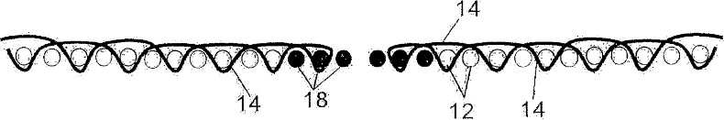
몇몇 예에 있어서, 다중 핀 혹은 핀틀 솔기들이 바람직하다. 이와 관련하여, 도 1B(평면도), 도 2B, 도 3A 및 3B(단면도)는 비대칭 단일 층 직물(10) 상에 있는 종래의 표준 이중 핀 솔기를 나타낸다. 도 1B에 도시된 바와 같이, 직물(10)은 교차기계방향사(12)로 이루어진 단일 층과 섞어 짜이는 기계방향사(14)의 다수의 열들을 포함한다. 솔기 영역에 있어서, 각각의 기계방향사(14)는 2개의 결합 핀들 혹은 핀틀(18) 주위로 시밍 루프(16)를 형성한다. 이러한 방식에 있어서, 이중 핀 솔기는 직물(10)의 두 단부들을 결합시키도록 사용된다. 도 3A 및 3B는 각각 설치 도중에 기계 상에서 직물(10)의 단면(좌측 및 우측 직물 단부들을 분리하여 나타내고, 두 핀들(18)은 설명의 편의를 위해서 2번 표시함)을 나타낸다. 핀들은 서로 얽힌 루프들과 솔기를 만들고 무한 직물을 만드는 재삽입된 핀들을 구비한 직물 단부들로부터 제거된다. 도시된 바와 같이, 기계방향사(14)의 제 1 열이 형성되고난 다음에 제 2 열이 형성되고, 완전한 폭 직물(10)을 형성하기 위하여 제 1 열과 제 2 열이 이러한 순서로 몇번이고 반복된다. In some instances, multiple pin or pintle seams are preferred. In this regard, FIGS. 1B (top view), FIGS. 2B, 3A, and 3B (sectional view) show a conventional standard double pin seam on an asymmetric
도 3A 및 3B에 각각 도시된 바와 같이, 직물 본체(즉, 비 솔기 영역)에서 직 조 패턴은 기계방향사(14)가 직물 표면 상에서 교차기계방향사(12) 위로 긴 플로트들을 한정하고 직물(10)의 배면 상에서 짧은 너클들을 한정하도록 이루어진다. 그런데, 이러한 솔기 영역에서의 직조 패턴은 직물 본체에서의 직조 패턴과는 다르다. 이러한 솔기 영역에 있어서, 기계방향사(14)는 직물 단부들에서 핀들(18) 주위로 루프들(16)을 형성한다. 직물 본체의 직조와 솔기 영역에서의 직조 사이의 불합치는 직물 표면에서의 불연속을 야기한다. 이러한 불연속이 도 2B(단면도)에 도시되어 있는데, 이는 제품이 직물 상에서 운반할 때 생기는 표식 및 사용중에 정적인 요소들(10)에 의한 직물의 솔기 영역의 마모를 야기할 수 있다.As shown in FIGS. 3A and 3B, respectively, the woven pattern in the fabric body (i.e., the non-seam area) results in the
이러한 불연속은 대칭적인 이중 층 직물 상에서 표준 이중 핀 솔기의 경우에도 또한 존재한다. 도 4D 및 4E에 각각 도시된 바와 같이, 2개의 핀들(18)을 사용하여 결합한 직물 단부들의 단면이 도시되어 있다(도 4E에서, 좌측 직물 단부와 우측 직물 단부는 분리하여 나타내었고, 2개의 핀들(18)은 설명의 편의를 위하여 2번 나타내었다). 도시된 바와 같이, 기계방향사(14)의 제 1 열이 형성된 다음에 제 2 열이 형성되고, 완전한 폭의 직물(10)을 형성하기 위해서 제 1 열과 제 2 열이 몇번이고 반복된다. This discontinuity is also present for standard double pin seams on symmetrical double layer fabrics. As shown in FIGS. 4D and 4E, respectively, cross-sections of fabric ends joined using two
도 4D 및 4E에 각각 도시된 바와 같이, 직물 본체에서 직조 패턴은 기계방향사(14)가 직물 표면과 직물의 배면 상에서 너클들을 한정하도록 이루어진다. 그런데, 솔기 영역에서 직조 패턴은 직물 본체에서의 직조 패턴과 다르다. 솔기 영역에서, 기계방향사(14)는 직물 단부들에서 핀들(18) 주위로 단순히 루프(16)를 형성한다. 몇몇 예에 있어서, 기계방향사(14)의 다른 열들은 다른 루프 길이와 기하학적 형상을 형성할 수 있고, 이것은 직물의 솔기와 본체 사이에서 불합치를 야기한다. 상기한 바와 같이, 직물 본체의 직조와 솔기 영역의 직조 사이의 이러한 불합치는 직물 표면에서의 불합치를 야기한다. 앞서 설명한 바와 같이, 이러한 불합치는 직물 상에 있는 제품의 표식과 정적인 물체에 의해서 직물 솔기의 마모를 야기할 수 있다.As shown in FIGS. 4D and 4E, respectively, the weave pattern in the fabric body is such that the
앞서 설명한 바와 같이, 직물의 나머지에 있는 직조 패턴과 거의 합치하는 직조 패턴을 갖는 솔기가 필요하다. As discussed above, there is a need for a seam having a weave pattern that closely matches the weave pattern in the rest of the fabric.
따라서, 본 발명은 직물을 결합시키도록 사용되는 것으로 3개 혹은 그 이상의 핀들 혹은 핀틀 주위로 시밍 루프들이 만들어지는 다중-핀 핀 솔기에 관한 것이다. 바람직하게는, 이러한 배열은 솔기 영역에서 마모의 위험성을 줄이거나 최소화하도록 불합치를 줄이거나 최소화하여 제품의 표식을 줄이거나 최소화하기 위하여, 솔기 영역에 있는 직조 패턴이 직물 본체에 있는 직조 패턴에 보다 근접하게 합치하는 결과를 야기한다.Accordingly, the present invention relates to a multi-pin pin seam where seaming loops are made around three or more pins or pintles, which are used to join the fabric. Preferably, this arrangement is closer to the weave pattern in the fabric body so that the weave pattern in the seam area is closer to the weave pattern in the fabric body in order to reduce or minimize the inconsistency of the product by reducing or minimizing inconsistencies to reduce or minimize the risk of wear in the seam area. Results in a good match.
이러한 점에서, 본 발명의 직물은 직물의 2개의 대향하는 단부들 사이에서 연장되는 다수의 기계방향사(MD yarns)와 짜여진 다수의 교차기계방향사(CD yarns)를 포함한다. 직물 단부들은 솔기 영역에서 교차기계방향으로 배치된 3개 또는 그 이상의 핀들 혹은 핀틀들에 의해서 함께 결합한다. 각각의 기계방향사는 솔기 영역에서 직조 패턴이 직물의 나머지에서의 직조 패턴에 거의 합치하도록 직물의 각 단부에서 하나 또는 그 이상의 교차기계방향 핀들 혹은 핀틀 주위로 고리를 형성한다.In this regard, the fabric of the present invention includes a plurality of MD yarns and a plurality of interwoven CD yarns woven, extending between two opposing ends of the fabric. The fabric ends are joined together by three or more pins or pintles arranged cross-machined in the seam area. Each machine direction yarn forms a loop around one or more cross-machine pins or pintles at each end of the fabric such that the weave pattern in the seam area substantially matches the weave pattern at the rest of the fabric.
본 발명의 보다 완벽한 이해를 돕기 위하여, 하기의 상세한 설명과 첨부 도면을 통한 참고가 이루어진다.In order to facilitate a more complete understanding of the present invention, reference is made to the following detailed description and accompanying drawings.
본 발명은 첨부 도면들을 참조한 하기의 상세한 설명을 통해서 명백하게 밝혀질 것이며, 첨부 도면에서 유사한 참조 부호들은 동일 또는 유사한 요소들과 부품들을 언급한다, 첨부 도면에서:BRIEF DESCRIPTION OF THE DRAWINGS The present invention will become apparent from the following detailed description with reference to the accompanying drawings, in which like reference numerals refer to the same or similar elements and parts, in the accompanying drawings:
도 1A는 본 발명에 따른 3중 핀 솔기의 평면도;1A is a top view of a triple pin seam in accordance with the present invention;
도 1B는 종래의 표준 이중 핀 솔기의 평면도;1B is a plan view of a conventional standard double pin seam;
도 2A는 본 발명에 따른 3중 핀 솔기의 단면도;2A is a cross-sectional view of a triple pin seam in accordance with the present invention;
도 2B는 종래의 표준 이중 핀 솔기의 단면도;2B is a cross-sectional view of a conventional standard double pin seam;
도 3A와 3B는 비대칭 단일 층 상에서 종래의 표준 이중 핀 솔기의 단면도;3A and 3B are cross-sectional views of conventional standard double pin seams on an asymmetric single layer;
도 3C 내지 3E는 본 발명에 따른 비대칭 단일 층 상에서 3중 핀 솔기의 단면도;3C-3E are cross-sectional views of triple pin seams on an asymmetric single layer in accordance with the present invention;
도 4A 내지 4C는 본 발명에 따른 이중 층 대칭 직물 상에서 4개의 핀 솔기의 단면도;4A-4C are cross-sectional views of four pin seams on a double layer symmetrical fabric in accordance with the present invention;
도 4D 및 4E는 이중 층 대칭 직물 상에서 종래의 표준 이중 핀 솔기의 단면도이다.4D and 4E are cross-sectional views of a conventional standard double pin seam on a double layer symmetric fabric.
도면들을 참조하면, 본 발명의 일 실시 예가 도 1A(평면도), 도 2A(단면도), 및 도 3C 내지 도 3E(단면도)에 도시되어 있다. 일반적으로, 이들 도면에 도시한 3중 핀 솔기는 종래의 이중 핀 솔기에 비해서 직물(10)의 표면에서 불연속성을 적게 나타낸다. 이것은 도 2A와 2B를 비교하면 명확하게 알 수 있는데, 시밍 루프들(seaming loops)이 도 2A에서는 정렬되어 있고, 도 2B에서는 직물 표면으로부터 벗어나 있는 것을 알 수 있다. 따라서, 도 2A에 있어서, 솔기 영역에서의 직조 패턴은, 종래에서 실행된 것에 비해서, 직물(10)의 나머지에 있는 직조 패턴에 거의 합치한다. 결과적으로, 사용중에 있어서, 제품이 직물(10) 상에서 운반할 때 생기는 표식 및 제품이 정적인 요소들 위를 지날 때 솔기 영역에서 야기되는 직물에 대한 마모가 줄어들거나 제거된다.Referring to the drawings, one embodiment of the present invention is shown in FIGS. 1A (top view), FIG. 2A (cross section), and FIGS. 3C-3E (cross section). In general, the triple pin seams shown in these figures exhibit less discontinuity at the surface of the
도 1A에 잘 도시된 바와 같이, 본 발명에 따른 직물(10)은 단일 층의 교차기계방향사(12)와 섞여 짜인 다수의 열의 기계방향사(14)를 포함한다. 솔기 영역에서, 각각의 기계방향사(14)는 3개의 교차기계방향 핀들 혹은 핀틀(18) 중 하나 또는 그 이상의 주위로 시밍 루프(16)를 형성한다. 이러한 방식으로, 3중 핀 솔기는 직물(10)의 두 단부들을 결합시키도록 사용된다. 이러한 직물(10)이 도 3C, 3D 및 3E에 단면도로 도시되어 있다(좌측과 우측 직물 단부들은 분리하여 나타내었고, 3개의 핀들(18)은 설명의 편의를 위해서 2번 나타내었다). 기계방향사(14)의 각 열을 도시하고 있는 도 3C 내지 3E에 도시된 바와 같이, 기계방향사(14)의 제 1 열(도 3C), 제 2 열(도 3D) 및 제 3 열(도 3E)은 교차기계방향사(12)의 층과 섞여 짜인다. 완전한 폭의 직물(10)을 형성하기 위해, 이러한 순서의 기계방향사 제 1, 제 2 및 제 3 열들이 반복된다. 부수적으로, 기계방향사(14), 교차기계방향사(12) 및 교차기계방향 핀들 혹은 핀틀(18)은, 비록 비원형과 같은 다른 단면형상을 가질 수도 있지만, 바람직하게는 원형 단면을 갖는다. 본 발명의 실시 예에 있어서, 교차기계방향 핀들 혹은 핀틀(18)은 교차기계방향사(12)와 동일한 직경을 가지며, 그러나 이것으로 제한되지 않고 용도에 따라 다른 직경을 가질 수 있다. 또한, 핀 또는 핀들은 적당한 중합체, 금속 혹은 특정 목적이나 용도에 적합한 다른 재료와 같이 기계방향사 혹은 교차기계방향사와 동일한 재료로 만들어지거나, 혹은 다르게 이루어질 것이다. As best shown in FIG. 1A, the
도 3C 내지 도 3E에 도시된 바와 같이, 비 솔기 영역 혹은 직물 본체에 있는 직조 패턴은 기계방향사(14)가 직물 표면에서 교차기계방향사(12) 위로 긴 플로트(long floats)를 한정하고 직물(10)의 배면에서 짧은 너클들(short knuckles)을 한정하도록 이루어진다. 특히, 기계방향사(14)는 3개의 연속적인 교차기계방향사(12)를 덮는 플로트를 한정한다. 각각의 플로트가 직물 표면을 덮은 후, 후면 상에 짧은 너클을 한정하기 위해서 기계방향사(14)가 단일의 교차기계방향사(12) 주위로 직조될 교차기계방향사 평면을 통과하고, 그런 후에 직물 표면에서 다른 긴 플로트를 한정하도록 직조된다. As shown in FIGS. 3C-3E, the weave pattern in the non-seam area or the fabric body is such that the
바람직하게도, 솔기 영역에 있는 직조 패턴은 직물 본체에 있는 직조 패턴과 거의 합치한다. 즉, 솔기 영역에 있어서, 기계방향사(14)는 직물 표면에서 연속적인 교차기계방향사와 핀들(18)에 걸쳐서 긴 플로트들을 형성하고, 직물 배면에서 짧은 너클들을 형성한다. 직물 본체에 있는 직조 패턴과 솔기 영역에 있는 직조 패턴 사이의 이러한 유사성 혹은 합치성의 결과, 종래의 핀 솔기들을 갖는 종래의 직물과 비교해서, 직물(10)의 표면에서 큰 연속성을 갖는다. 시밍 루프들이 직물 본 체와 정렬되어 있는 곳에서 직물 표면에서의 합치가 도 2A(단면도)에 명백하게 도시되어 있고, 상기한 바와 같이, 사용중에 있어서 제품이 직물 상에서 운반할 때 생기는 표식 및 제품이 정적인 요소들 위를 지날 때 솔기 영역에서 야기되는 직물에 대한 마모가 줄어들거나 제거된다.Preferably, the weave pattern in the seam area substantially matches the weave pattern in the fabric body. In other words, in the seam area, the
직물 표면에서의 이러한 합치는 본 발명의 다른 실시 예에 따른 대칭적인 이중 층 직물(10) 상에서 4개의 핀 솔기의 경우에도 또한 제공된다. 도 4A 내지 도 4C는 4개의 핀들(18)을 사용하여 결합한 직물(10)의 단면도들이다(도 4B에서는 도4C의 직물을 좌측과 우측 직물 단부들로 분리하여 나타내었고, 4개의 핀들(18)은 설명의 편의를 위해서 2번 나타내었다). 도 4A 및 4C에 도시된 바와 같이, 기계방향사(14)의 제 1 열(도 4A)과 제 2 열(도 4B)은 교차기계방향사(12)의 이중 층과 섞여 짜인다. 완전한 폭의 직물(10)을 형성하기 위해, 이러한 순서의 제 1 및 제 2 기계방향사 열들이 반복된다. This matching at the fabric surface is also provided in the case of four pin seams on a symmetrical
도 4A 내지 도 4C에 도시된 바와 같이, 직물 본체에서의 직조는 기계방향사(14)가 직물 표면과 직물 배면 모두에서 짧은 너클들을 한정하도록 이루어진다. 그러므로, 솔기 영역에 있는 직조 패턴은 직물 본체에 있는 직조 패턴에 거의 합치한다. 그러므로, 솔기 영역에서, 기계방향사(14)는 직물 표면과 직물 배면에서 핀들 위로 너클들을 또한 한정한다. 상기한 바와 같이, 직물 본체에 있는 직조 패턴과 솔기 영역에 있는 직조 패턴 사이의 이러한 합치는 종래 기술에 따른 이중 핀 솔기들과 연관된 제품운반 표식 및/또는 직물 마모를 줄이거나 감소시키게 된다. As shown in FIGS. 4A-4C, the weaving in the fabric body is such that the
제지 산업, 특히 건조기 직물에서 사용될 다른 직물이나 벨트들에 추가하여 부직포, 골판형성 벨트, 펄프형성 직물, 슬러지 탈수 직물, DNT 탈수 직물 분야의 폭넓은 산업용 직물 분야에 본 발명이 적용 가능함을 해당 기술분야의 숙련된 당업자는 쉽게 이해할 수 있을 것이다. The invention is applicable to a wide range of industrial fabrics in the field of nonwovens, corrugated belts, pulp forming fabrics, sludge dewatering fabrics, DNT dewatering fabrics in addition to other fabrics or belts to be used in the paper industry, in particular dryer fabrics. Those skilled in the art will readily understand.
상기에서는 본 발명의 바람직한 실시 예를 참조하여 설명하였지만, 해당기술분야의 숙련된 당업자는 하기의 특허청구범위에 기재된 본 발명의 사상 및 영역으로부터 벗어나지 않는 범위 내에서 본 발명을 다양하게 수정 및 변경시킬 수 있음을 이해할 수 있을 것이다. Although the above has been described with reference to a preferred embodiment of the present invention, those skilled in the art will be able to variously modify and change the present invention without departing from the spirit and scope of the invention described in the claims below. It will be appreciated.
Claims (18)
Applications Claiming Priority (3)
| Application Number | Priority Date | Filing Date | Title |
|---|---|---|---|
| US11/012,530 US7093621B2 (en) | 2004-12-15 | 2004-12-15 | Multi-pin pin seam for an industrial fabric |
| US11/012,530 | 2004-12-15 | ||
| PCT/US2005/042257 WO2006065465A1 (en) | 2004-12-15 | 2005-11-21 | Multi-pin pin seam for an industrial fabric |
Publications (2)
| Publication Number | Publication Date |
|---|---|
| KR20070091017A KR20070091017A (en) | 2007-09-06 |
| KR101299001B1 true KR101299001B1 (en) | 2013-08-23 |
Family
ID=35811737
Family Applications (1)
| Application Number | Title | Priority Date | Filing Date |
|---|---|---|---|
| KR1020077016223A KR101299001B1 (en) | 2004-12-15 | 2005-11-21 | Multi-pin pin seam for an industrial fabric |
Country Status (19)
| Country | Link |
|---|---|
| US (1) | US7093621B2 (en) |
| EP (1) | EP1834037B1 (en) |
| JP (1) | JP4950066B2 (en) |
| KR (1) | KR101299001B1 (en) |
| CN (1) | CN101080531B (en) |
| AT (1) | ATE462828T1 (en) |
| AU (1) | AU2005316953A1 (en) |
| BR (1) | BRPI0518108B1 (en) |
| CA (1) | CA2590162C (en) |
| DE (1) | DE602005020355D1 (en) |
| ES (1) | ES2343849T3 (en) |
| MX (1) | MX2007007037A (en) |
| NO (1) | NO20073613L (en) |
| PL (1) | PL1834037T3 (en) |
| PT (1) | PT1834037E (en) |
| RU (1) | RU2382842C2 (en) |
| TW (1) | TWI346166B (en) |
| WO (1) | WO2006065465A1 (en) |
| ZA (1) | ZA200704834B (en) |
Families Citing this family (3)
| Publication number | Priority date | Publication date | Assignee | Title |
|---|---|---|---|---|
| DE602004027169D1 (en) * | 2004-03-19 | 2010-06-24 | Astenjohnson Inc | TROCKENSIEBNAHT |
| GB2428693A (en) * | 2005-08-02 | 2007-02-07 | Brent Swaine | Woven papermaking fabric with seam |
| CN104642134A (en) * | 2015-02-16 | 2015-05-27 | 钱家静 | Large-scale manufacturing method of high-precision improved Nitsch culture matrices |
Citations (4)
| Publication number | Priority date | Publication date | Assignee | Title |
|---|---|---|---|---|
| US4883096A (en) * | 1988-05-04 | 1989-11-28 | Asten Group, Inc. | Seam design for seamed felts |
| JPH0268387A (en) * | 1988-05-04 | 1990-03-07 | Asten Group Inc | Textile for a papermaking machine |
| JPH0268389A (en) * | 1988-05-04 | 1990-03-07 | Asten Group Inc | Apparatus for making a paper board |
| JP2003522856A (en) * | 2000-02-14 | 2003-07-29 | アルバニー インターナショナル コーポレイション | Industrial cloth to be seamed |
Family Cites Families (18)
| Publication number | Priority date | Publication date | Assignee | Title |
|---|---|---|---|---|
| GB1432357A (en) * | 1972-09-23 | 1976-04-14 | Jwi Ltd | Woven cloth seam |
| US4186780A (en) * | 1978-12-15 | 1980-02-05 | Albany International Corp. | Seam construction for multi-layer felts |
| US4418726A (en) * | 1981-01-12 | 1983-12-06 | Albany International Corp. | Double loop seam for corrugator belts |
| FR2578869B1 (en) * | 1985-03-12 | 1988-09-30 | Binet Feutres Sa | JUNCTION DEVICE FOR WET PRESS FELT AND STATIONARY CANVAS. |
| US4887648A (en) * | 1987-06-24 | 1989-12-19 | Asten Group, Inc. | Method for making a multi-layered papermakers fabric with seam |
| US4846231A (en) * | 1988-05-04 | 1989-07-11 | Asten Group, Inc. | Seam design for seamed felts |
| US4896702A (en) * | 1988-12-01 | 1990-01-30 | Niagara Lockport Industries Inc. | Seam construction for papermaking fabrics |
| US5488976A (en) | 1994-03-16 | 1996-02-06 | Asten, Inc. | Coil seam for single layer industrial fabrics having an uneven shed pattern |
| US5601877A (en) * | 1994-06-09 | 1997-02-11 | Albany International Corp. | Method of seam closure for sheet transfer and other paper processing belts |
| US5503196A (en) * | 1994-12-07 | 1996-04-02 | Albany International Corp. | Papermakers fabric having a system of machine-direction yarns residing interior of the fabric surfaces |
| US5601120A (en) * | 1996-01-30 | 1997-02-11 | Asten, Inc. | Pin seam with double end loops and method |
| US5875822A (en) * | 1996-06-25 | 1999-03-02 | Albany International Corp. | Polyamide spiral seam for seamed papermakers' fabrics |
| US5769131A (en) * | 1997-05-16 | 1998-06-23 | Albany International Corp. | Seam design for a dryer fabric |
| US5904187A (en) * | 1997-10-22 | 1999-05-18 | Albany International Corp. | Seam integrity in multiple layer/multiple seam press fabrics |
| US6194331B1 (en) * | 1998-03-05 | 2001-02-27 | Albany International Corp. | Flow-resistant material additions to double-seam on machine-seamable fabrics |
| FR2789702B1 (en) * | 1999-02-16 | 2001-03-30 | Cofpa | SYMMETRICAL WEAVE JUNCTION FOR ASYMMETRIC WEAVE WEBBAND |
| US6213164B1 (en) * | 1999-03-11 | 2001-04-10 | Geschmay Corporation | Pintle seamed press felt |
| US6508278B1 (en) * | 2001-11-23 | 2003-01-21 | Albany International Corp. | Seam enhancements for seamed papermaker's fabrics |
-
2004
- 2004-12-15 US US11/012,530 patent/US7093621B2/en active Active
-
2005
- 2005-11-21 AU AU2005316953A patent/AU2005316953A1/en not_active Abandoned
- 2005-11-21 BR BRPI0518108A patent/BRPI0518108B1/en active IP Right Grant
- 2005-11-21 AT AT05824816T patent/ATE462828T1/en active
- 2005-11-21 PL PL05824816T patent/PL1834037T3/en unknown
- 2005-11-21 ES ES05824816T patent/ES2343849T3/en active Active
- 2005-11-21 ZA ZA200704834A patent/ZA200704834B/en unknown
- 2005-11-21 CN CN2005800430916A patent/CN101080531B/en active Active
- 2005-11-21 JP JP2007546686A patent/JP4950066B2/en active Active
- 2005-11-21 KR KR1020077016223A patent/KR101299001B1/en active IP Right Grant
- 2005-11-21 RU RU2007118469/12A patent/RU2382842C2/en active
- 2005-11-21 WO PCT/US2005/042257 patent/WO2006065465A1/en active Application Filing
- 2005-11-21 DE DE602005020355T patent/DE602005020355D1/en active Active
- 2005-11-21 PT PT05824816T patent/PT1834037E/en unknown
- 2005-11-21 EP EP05824816A patent/EP1834037B1/en active Active
- 2005-11-21 CA CA2590162A patent/CA2590162C/en active Active
- 2005-11-21 MX MX2007007037A patent/MX2007007037A/en active IP Right Grant
- 2005-11-28 TW TW094141683A patent/TWI346166B/en active
-
2007
- 2007-07-13 NO NO20073613A patent/NO20073613L/en not_active Application Discontinuation
Patent Citations (4)
| Publication number | Priority date | Publication date | Assignee | Title |
|---|---|---|---|---|
| US4883096A (en) * | 1988-05-04 | 1989-11-28 | Asten Group, Inc. | Seam design for seamed felts |
| JPH0268387A (en) * | 1988-05-04 | 1990-03-07 | Asten Group Inc | Textile for a papermaking machine |
| JPH0268389A (en) * | 1988-05-04 | 1990-03-07 | Asten Group Inc | Apparatus for making a paper board |
| JP2003522856A (en) * | 2000-02-14 | 2003-07-29 | アルバニー インターナショナル コーポレイション | Industrial cloth to be seamed |
Also Published As
| Publication number | Publication date |
|---|---|
| AU2005316953A1 (en) | 2006-06-22 |
| EP1834037A1 (en) | 2007-09-19 |
| BRPI0518108A (en) | 2008-11-04 |
| NO20073613L (en) | 2007-07-13 |
| BRPI0518108B1 (en) | 2015-09-08 |
| ES2343849T3 (en) | 2010-08-11 |
| CN101080531B (en) | 2012-07-04 |
| ATE462828T1 (en) | 2010-04-15 |
| JP2008524459A (en) | 2008-07-10 |
| TW200628651A (en) | 2006-08-16 |
| RU2382842C2 (en) | 2010-02-27 |
| ZA200704834B (en) | 2008-10-29 |
| US20060124192A1 (en) | 2006-06-15 |
| WO2006065465A1 (en) | 2006-06-22 |
| RU2007118469A (en) | 2009-01-27 |
| US7093621B2 (en) | 2006-08-22 |
| TWI346166B (en) | 2011-08-01 |
| EP1834037B1 (en) | 2010-03-31 |
| DE602005020355D1 (en) | 2010-05-12 |
| MX2007007037A (en) | 2007-08-03 |
| CA2590162C (en) | 2010-09-14 |
| CN101080531A (en) | 2007-11-28 |
| KR20070091017A (en) | 2007-09-06 |
| PL1834037T3 (en) | 2010-08-31 |
| JP4950066B2 (en) | 2012-06-13 |
| CA2590162A1 (en) | 2006-06-22 |
| PT1834037E (en) | 2010-07-01 |
Similar Documents
| Publication | Publication Date | Title |
|---|---|---|
| CA2928854C (en) | Multiaxial fabric having reduced interference pattern | |
| JP2563842B2 (en) | Fabric for papermaking | |
| KR100405084B1 (en) | A press fabric for the press section of a paper machine and manufacturing method therefor | |
| KR100834175B1 (en) | Four-layer seamed press fabric | |
| KR100853316B1 (en) | On-machine-seamable papermaker's fabric | |
| KR20060093071A (en) | Papermaker's forming fabric with machine direction stitching yarns that form machine side knuckles | |
| KR101299001B1 (en) | Multi-pin pin seam for an industrial fabric | |
| KR101118110B1 (en) | Grooved shoe press belt with conical rebates | |
| KR20230110819A (en) | Continuous weave dry fabric for paper machine | |
| AU2011205220A1 (en) | Multiaxial Fabric Having Reduced Interference Pattern |
Legal Events
| Date | Code | Title | Description |
|---|---|---|---|
| A201 | Request for examination | ||
| E902 | Notification of reason for refusal | ||
| E701 | Decision to grant or registration of patent right | ||
| GRNT | Written decision to grant | ||
| FPAY | Annual fee payment |
Payment date: 20160805 Year of fee payment: 4 |
|
| FPAY | Annual fee payment |
Payment date: 20170808 Year of fee payment: 5 |
|
| FPAY | Annual fee payment |
Payment date: 20180807 Year of fee payment: 6 |
|
| FPAY | Annual fee payment |
Payment date: 20190806 Year of fee payment: 7 |