KR101257123B1 - Gap adjustment for an ultrasonic welding system - Google Patents
Gap adjustment for an ultrasonic welding system Download PDFInfo
- Publication number
- KR101257123B1 KR101257123B1 KR1020077014919A KR20077014919A KR101257123B1 KR 101257123 B1 KR101257123 B1 KR 101257123B1 KR 1020077014919 A KR1020077014919 A KR 1020077014919A KR 20077014919 A KR20077014919 A KR 20077014919A KR 101257123 B1 KR101257123 B1 KR 101257123B1
- Authority
- KR
- South Korea
- Prior art keywords
- horn
- gap
- anvil
- force
- delete delete
- Prior art date
Links
Images


Classifications
-
- B—PERFORMING OPERATIONS; TRANSPORTING
- B29—WORKING OF PLASTICS; WORKING OF SUBSTANCES IN A PLASTIC STATE IN GENERAL
- B29C—SHAPING OR JOINING OF PLASTICS; SHAPING OF MATERIAL IN A PLASTIC STATE, NOT OTHERWISE PROVIDED FOR; AFTER-TREATMENT OF THE SHAPED PRODUCTS, e.g. REPAIRING
- B29C65/00—Joining or sealing of preformed parts, e.g. welding of plastics materials; Apparatus therefor
- B29C65/02—Joining or sealing of preformed parts, e.g. welding of plastics materials; Apparatus therefor by heating, with or without pressure
- B29C65/08—Joining or sealing of preformed parts, e.g. welding of plastics materials; Apparatus therefor by heating, with or without pressure using ultrasonic vibrations
-
- B—PERFORMING OPERATIONS; TRANSPORTING
- B29—WORKING OF PLASTICS; WORKING OF SUBSTANCES IN A PLASTIC STATE IN GENERAL
- B29C—SHAPING OR JOINING OF PLASTICS; SHAPING OF MATERIAL IN A PLASTIC STATE, NOT OTHERWISE PROVIDED FOR; AFTER-TREATMENT OF THE SHAPED PRODUCTS, e.g. REPAIRING
- B29C66/00—General aspects of processes or apparatus for joining preformed parts
- B29C66/90—Measuring or controlling the joining process
- B29C66/92—Measuring or controlling the joining process by measuring or controlling the pressure, the force, the mechanical power or the displacement of the joining tools
- B29C66/924—Measuring or controlling the joining process by measuring or controlling the pressure, the force, the mechanical power or the displacement of the joining tools by controlling or regulating the pressure, the force, the mechanical power or the displacement of the joining tools
- B29C66/9261—Measuring or controlling the joining process by measuring or controlling the pressure, the force, the mechanical power or the displacement of the joining tools by controlling or regulating the pressure, the force, the mechanical power or the displacement of the joining tools by controlling or regulating the displacement of the joining tools
- B29C66/92651—Measuring or controlling the joining process by measuring or controlling the pressure, the force, the mechanical power or the displacement of the joining tools by controlling or regulating the pressure, the force, the mechanical power or the displacement of the joining tools by controlling or regulating the displacement of the joining tools by using stops
-
- B—PERFORMING OPERATIONS; TRANSPORTING
- B29—WORKING OF PLASTICS; WORKING OF SUBSTANCES IN A PLASTIC STATE IN GENERAL
- B29C—SHAPING OR JOINING OF PLASTICS; SHAPING OF MATERIAL IN A PLASTIC STATE, NOT OTHERWISE PROVIDED FOR; AFTER-TREATMENT OF THE SHAPED PRODUCTS, e.g. REPAIRING
- B29C65/00—Joining or sealing of preformed parts, e.g. welding of plastics materials; Apparatus therefor
- B29C65/02—Joining or sealing of preformed parts, e.g. welding of plastics materials; Apparatus therefor by heating, with or without pressure
- B29C65/08—Joining or sealing of preformed parts, e.g. welding of plastics materials; Apparatus therefor by heating, with or without pressure using ultrasonic vibrations
- B29C65/083—Joining or sealing of preformed parts, e.g. welding of plastics materials; Apparatus therefor by heating, with or without pressure using ultrasonic vibrations using a rotary sonotrode or a rotary anvil
- B29C65/085—Joining or sealing of preformed parts, e.g. welding of plastics materials; Apparatus therefor by heating, with or without pressure using ultrasonic vibrations using a rotary sonotrode or a rotary anvil using a rotary sonotrode
-
- B—PERFORMING OPERATIONS; TRANSPORTING
- B29—WORKING OF PLASTICS; WORKING OF SUBSTANCES IN A PLASTIC STATE IN GENERAL
- B29C—SHAPING OR JOINING OF PLASTICS; SHAPING OF MATERIAL IN A PLASTIC STATE, NOT OTHERWISE PROVIDED FOR; AFTER-TREATMENT OF THE SHAPED PRODUCTS, e.g. REPAIRING
- B29C66/00—General aspects of processes or apparatus for joining preformed parts
- B29C66/80—General aspects of machine operations or constructions and parts thereof
- B29C66/81—General aspects of the pressing elements, i.e. the elements applying pressure on the parts to be joined in the area to be joined, e.g. the welding jaws or clamps
- B29C66/812—General aspects of the pressing elements, i.e. the elements applying pressure on the parts to be joined in the area to be joined, e.g. the welding jaws or clamps characterised by the composition, by the structure, by the intensive physical properties or by the optical properties of the material constituting the pressing elements, e.g. constituting the welding jaws or clamps
- B29C66/8126—General aspects of the pressing elements, i.e. the elements applying pressure on the parts to be joined in the area to be joined, e.g. the welding jaws or clamps characterised by the composition, by the structure, by the intensive physical properties or by the optical properties of the material constituting the pressing elements, e.g. constituting the welding jaws or clamps characterised by the intensive physical properties or by the optical properties of the material constituting the pressing elements, e.g. constituting the welding jaws or clamps
- B29C66/81261—Thermal properties, e.g. thermal conductivity, thermal expansion coefficient
-
- B—PERFORMING OPERATIONS; TRANSPORTING
- B29—WORKING OF PLASTICS; WORKING OF SUBSTANCES IN A PLASTIC STATE IN GENERAL
- B29C—SHAPING OR JOINING OF PLASTICS; SHAPING OF MATERIAL IN A PLASTIC STATE, NOT OTHERWISE PROVIDED FOR; AFTER-TREATMENT OF THE SHAPED PRODUCTS, e.g. REPAIRING
- B29C66/00—General aspects of processes or apparatus for joining preformed parts
- B29C66/80—General aspects of machine operations or constructions and parts thereof
- B29C66/81—General aspects of the pressing elements, i.e. the elements applying pressure on the parts to be joined in the area to be joined, e.g. the welding jaws or clamps
- B29C66/818—General aspects of the pressing elements, i.e. the elements applying pressure on the parts to be joined in the area to be joined, e.g. the welding jaws or clamps characterised by the cooling constructional aspects, or by the thermal or electrical insulating or conducting constructional aspects of the welding jaws or of the clamps ; comprising means for compensating for the thermal expansion of the welding jaws or of the clamps
- B29C66/8185—General aspects of the pressing elements, i.e. the elements applying pressure on the parts to be joined in the area to be joined, e.g. the welding jaws or clamps characterised by the cooling constructional aspects, or by the thermal or electrical insulating or conducting constructional aspects of the welding jaws or of the clamps ; comprising means for compensating for the thermal expansion of the welding jaws or of the clamps comprising means for compensating for the thermal expansion of the welding jaws or of the clamps
-
- B—PERFORMING OPERATIONS; TRANSPORTING
- B29—WORKING OF PLASTICS; WORKING OF SUBSTANCES IN A PLASTIC STATE IN GENERAL
- B29C—SHAPING OR JOINING OF PLASTICS; SHAPING OF MATERIAL IN A PLASTIC STATE, NOT OTHERWISE PROVIDED FOR; AFTER-TREATMENT OF THE SHAPED PRODUCTS, e.g. REPAIRING
- B29C66/00—General aspects of processes or apparatus for joining preformed parts
- B29C66/80—General aspects of machine operations or constructions and parts thereof
- B29C66/82—Pressure application arrangements, e.g. transmission or actuating mechanisms for joining tools or clamps
- B29C66/824—Actuating mechanisms
- B29C66/8242—Pneumatic or hydraulic drives
- B29C66/82421—Pneumatic or hydraulic drives using an inflatable element positioned between the joining tool and a backing-up part
-
- B—PERFORMING OPERATIONS; TRANSPORTING
- B29—WORKING OF PLASTICS; WORKING OF SUBSTANCES IN A PLASTIC STATE IN GENERAL
- B29C—SHAPING OR JOINING OF PLASTICS; SHAPING OF MATERIAL IN A PLASTIC STATE, NOT OTHERWISE PROVIDED FOR; AFTER-TREATMENT OF THE SHAPED PRODUCTS, e.g. REPAIRING
- B29C66/00—General aspects of processes or apparatus for joining preformed parts
- B29C66/80—General aspects of machine operations or constructions and parts thereof
- B29C66/83—General aspects of machine operations or constructions and parts thereof characterised by the movement of the joining or pressing tools
- B29C66/832—Reciprocating joining or pressing tools
- B29C66/8322—Joining or pressing tools reciprocating along one axis
-
- B—PERFORMING OPERATIONS; TRANSPORTING
- B29—WORKING OF PLASTICS; WORKING OF SUBSTANCES IN A PLASTIC STATE IN GENERAL
- B29C—SHAPING OR JOINING OF PLASTICS; SHAPING OF MATERIAL IN A PLASTIC STATE, NOT OTHERWISE PROVIDED FOR; AFTER-TREATMENT OF THE SHAPED PRODUCTS, e.g. REPAIRING
- B29C66/00—General aspects of processes or apparatus for joining preformed parts
- B29C66/80—General aspects of machine operations or constructions and parts thereof
- B29C66/83—General aspects of machine operations or constructions and parts thereof characterised by the movement of the joining or pressing tools
- B29C66/834—General aspects of machine operations or constructions and parts thereof characterised by the movement of the joining or pressing tools moving with the parts to be joined
- B29C66/8341—Roller, cylinder or drum types; Band or belt types; Ball types
- B29C66/83411—Roller, cylinder or drum types
-
- B—PERFORMING OPERATIONS; TRANSPORTING
- B29—WORKING OF PLASTICS; WORKING OF SUBSTANCES IN A PLASTIC STATE IN GENERAL
- B29C—SHAPING OR JOINING OF PLASTICS; SHAPING OF MATERIAL IN A PLASTIC STATE, NOT OTHERWISE PROVIDED FOR; AFTER-TREATMENT OF THE SHAPED PRODUCTS, e.g. REPAIRING
- B29C66/00—General aspects of processes or apparatus for joining preformed parts
- B29C66/90—Measuring or controlling the joining process
- B29C66/91—Measuring or controlling the joining process by measuring or controlling the temperature, the heat or the thermal flux
- B29C66/912—Measuring or controlling the joining process by measuring or controlling the temperature, the heat or the thermal flux by measuring the temperature, the heat or the thermal flux
- B29C66/9121—Measuring or controlling the joining process by measuring or controlling the temperature, the heat or the thermal flux by measuring the temperature, the heat or the thermal flux by measuring the temperature
- B29C66/91231—Measuring or controlling the joining process by measuring or controlling the temperature, the heat or the thermal flux by measuring the temperature, the heat or the thermal flux by measuring the temperature of the joining tool
-
- B—PERFORMING OPERATIONS; TRANSPORTING
- B29—WORKING OF PLASTICS; WORKING OF SUBSTANCES IN A PLASTIC STATE IN GENERAL
- B29C—SHAPING OR JOINING OF PLASTICS; SHAPING OF MATERIAL IN A PLASTIC STATE, NOT OTHERWISE PROVIDED FOR; AFTER-TREATMENT OF THE SHAPED PRODUCTS, e.g. REPAIRING
- B29C66/00—General aspects of processes or apparatus for joining preformed parts
- B29C66/90—Measuring or controlling the joining process
- B29C66/91—Measuring or controlling the joining process by measuring or controlling the temperature, the heat or the thermal flux
- B29C66/914—Measuring or controlling the joining process by measuring or controlling the temperature, the heat or the thermal flux by controlling or regulating the temperature, the heat or the thermal flux
- B29C66/9141—Measuring or controlling the joining process by measuring or controlling the temperature, the heat or the thermal flux by controlling or regulating the temperature, the heat or the thermal flux by controlling or regulating the temperature
- B29C66/91421—Measuring or controlling the joining process by measuring or controlling the temperature, the heat or the thermal flux by controlling or regulating the temperature, the heat or the thermal flux by controlling or regulating the temperature of the joining tools
-
- B—PERFORMING OPERATIONS; TRANSPORTING
- B29—WORKING OF PLASTICS; WORKING OF SUBSTANCES IN A PLASTIC STATE IN GENERAL
- B29C—SHAPING OR JOINING OF PLASTICS; SHAPING OF MATERIAL IN A PLASTIC STATE, NOT OTHERWISE PROVIDED FOR; AFTER-TREATMENT OF THE SHAPED PRODUCTS, e.g. REPAIRING
- B29C66/00—General aspects of processes or apparatus for joining preformed parts
- B29C66/90—Measuring or controlling the joining process
- B29C66/91—Measuring or controlling the joining process by measuring or controlling the temperature, the heat or the thermal flux
- B29C66/914—Measuring or controlling the joining process by measuring or controlling the temperature, the heat or the thermal flux by controlling or regulating the temperature, the heat or the thermal flux
- B29C66/9141—Measuring or controlling the joining process by measuring or controlling the temperature, the heat or the thermal flux by controlling or regulating the temperature, the heat or the thermal flux by controlling or regulating the temperature
- B29C66/91431—Measuring or controlling the joining process by measuring or controlling the temperature, the heat or the thermal flux by controlling or regulating the temperature, the heat or the thermal flux by controlling or regulating the temperature the temperature being kept constant over time
-
- B—PERFORMING OPERATIONS; TRANSPORTING
- B29—WORKING OF PLASTICS; WORKING OF SUBSTANCES IN A PLASTIC STATE IN GENERAL
- B29C—SHAPING OR JOINING OF PLASTICS; SHAPING OF MATERIAL IN A PLASTIC STATE, NOT OTHERWISE PROVIDED FOR; AFTER-TREATMENT OF THE SHAPED PRODUCTS, e.g. REPAIRING
- B29C66/00—General aspects of processes or apparatus for joining preformed parts
- B29C66/90—Measuring or controlling the joining process
- B29C66/92—Measuring or controlling the joining process by measuring or controlling the pressure, the force, the mechanical power or the displacement of the joining tools
- B29C66/924—Measuring or controlling the joining process by measuring or controlling the pressure, the force, the mechanical power or the displacement of the joining tools by controlling or regulating the pressure, the force, the mechanical power or the displacement of the joining tools
- B29C66/9241—Measuring or controlling the joining process by measuring or controlling the pressure, the force, the mechanical power or the displacement of the joining tools by controlling or regulating the pressure, the force, the mechanical power or the displacement of the joining tools by controlling or regulating the pressure, the force or the mechanical power
-
- B—PERFORMING OPERATIONS; TRANSPORTING
- B29—WORKING OF PLASTICS; WORKING OF SUBSTANCES IN A PLASTIC STATE IN GENERAL
- B29C—SHAPING OR JOINING OF PLASTICS; SHAPING OF MATERIAL IN A PLASTIC STATE, NOT OTHERWISE PROVIDED FOR; AFTER-TREATMENT OF THE SHAPED PRODUCTS, e.g. REPAIRING
- B29C66/00—General aspects of processes or apparatus for joining preformed parts
- B29C66/90—Measuring or controlling the joining process
- B29C66/92—Measuring or controlling the joining process by measuring or controlling the pressure, the force, the mechanical power or the displacement of the joining tools
- B29C66/924—Measuring or controlling the joining process by measuring or controlling the pressure, the force, the mechanical power or the displacement of the joining tools by controlling or regulating the pressure, the force, the mechanical power or the displacement of the joining tools
- B29C66/9261—Measuring or controlling the joining process by measuring or controlling the pressure, the force, the mechanical power or the displacement of the joining tools by controlling or regulating the pressure, the force, the mechanical power or the displacement of the joining tools by controlling or regulating the displacement of the joining tools
- B29C66/92611—Measuring or controlling the joining process by measuring or controlling the pressure, the force, the mechanical power or the displacement of the joining tools by controlling or regulating the pressure, the force, the mechanical power or the displacement of the joining tools by controlling or regulating the displacement of the joining tools by controlling or regulating the gap between the joining tools
- B29C66/92613—Measuring or controlling the joining process by measuring or controlling the pressure, the force, the mechanical power or the displacement of the joining tools by controlling or regulating the pressure, the force, the mechanical power or the displacement of the joining tools by controlling or regulating the displacement of the joining tools by controlling or regulating the gap between the joining tools the gap being kept constant over time
-
- B—PERFORMING OPERATIONS; TRANSPORTING
- B29—WORKING OF PLASTICS; WORKING OF SUBSTANCES IN A PLASTIC STATE IN GENERAL
- B29C—SHAPING OR JOINING OF PLASTICS; SHAPING OF MATERIAL IN A PLASTIC STATE, NOT OTHERWISE PROVIDED FOR; AFTER-TREATMENT OF THE SHAPED PRODUCTS, e.g. REPAIRING
- B29C66/00—General aspects of processes or apparatus for joining preformed parts
- B29C66/90—Measuring or controlling the joining process
- B29C66/95—Measuring or controlling the joining process by measuring or controlling specific variables not covered by groups B29C66/91 - B29C66/94
- B29C66/951—Measuring or controlling the joining process by measuring or controlling specific variables not covered by groups B29C66/91 - B29C66/94 by measuring or controlling the vibration frequency and/or the vibration amplitude of vibrating joining tools, e.g. of ultrasonic welding tools
- B29C66/9515—Measuring or controlling the joining process by measuring or controlling specific variables not covered by groups B29C66/91 - B29C66/94 by measuring or controlling the vibration frequency and/or the vibration amplitude of vibrating joining tools, e.g. of ultrasonic welding tools by measuring their vibration amplitude
-
- B—PERFORMING OPERATIONS; TRANSPORTING
- B29—WORKING OF PLASTICS; WORKING OF SUBSTANCES IN A PLASTIC STATE IN GENERAL
- B29C—SHAPING OR JOINING OF PLASTICS; SHAPING OF MATERIAL IN A PLASTIC STATE, NOT OTHERWISE PROVIDED FOR; AFTER-TREATMENT OF THE SHAPED PRODUCTS, e.g. REPAIRING
- B29C66/00—General aspects of processes or apparatus for joining preformed parts
- B29C66/90—Measuring or controlling the joining process
- B29C66/95—Measuring or controlling the joining process by measuring or controlling specific variables not covered by groups B29C66/91 - B29C66/94
- B29C66/951—Measuring or controlling the joining process by measuring or controlling specific variables not covered by groups B29C66/91 - B29C66/94 by measuring or controlling the vibration frequency and/or the vibration amplitude of vibrating joining tools, e.g. of ultrasonic welding tools
- B29C66/9516—Measuring or controlling the joining process by measuring or controlling specific variables not covered by groups B29C66/91 - B29C66/94 by measuring or controlling the vibration frequency and/or the vibration amplitude of vibrating joining tools, e.g. of ultrasonic welding tools by controlling their vibration amplitude
-
- B—PERFORMING OPERATIONS; TRANSPORTING
- B29—WORKING OF PLASTICS; WORKING OF SUBSTANCES IN A PLASTIC STATE IN GENERAL
- B29C—SHAPING OR JOINING OF PLASTICS; SHAPING OF MATERIAL IN A PLASTIC STATE, NOT OTHERWISE PROVIDED FOR; AFTER-TREATMENT OF THE SHAPED PRODUCTS, e.g. REPAIRING
- B29C66/00—General aspects of processes or apparatus for joining preformed parts
- B29C66/90—Measuring or controlling the joining process
- B29C66/96—Measuring or controlling the joining process characterised by the method for implementing the controlling of the joining process
- B29C66/961—Measuring or controlling the joining process characterised by the method for implementing the controlling of the joining process involving a feedback loop mechanism, e.g. comparison with a desired value
-
- B—PERFORMING OPERATIONS; TRANSPORTING
- B29—WORKING OF PLASTICS; WORKING OF SUBSTANCES IN A PLASTIC STATE IN GENERAL
- B29C—SHAPING OR JOINING OF PLASTICS; SHAPING OF MATERIAL IN A PLASTIC STATE, NOT OTHERWISE PROVIDED FOR; AFTER-TREATMENT OF THE SHAPED PRODUCTS, e.g. REPAIRING
- B29C65/00—Joining or sealing of preformed parts, e.g. welding of plastics materials; Apparatus therefor
- B29C65/02—Joining or sealing of preformed parts, e.g. welding of plastics materials; Apparatus therefor by heating, with or without pressure
- B29C65/08—Joining or sealing of preformed parts, e.g. welding of plastics materials; Apparatus therefor by heating, with or without pressure using ultrasonic vibrations
- B29C65/081—Joining or sealing of preformed parts, e.g. welding of plastics materials; Apparatus therefor by heating, with or without pressure using ultrasonic vibrations having a component of vibration not perpendicular to the welding surface
-
- B—PERFORMING OPERATIONS; TRANSPORTING
- B29—WORKING OF PLASTICS; WORKING OF SUBSTANCES IN A PLASTIC STATE IN GENERAL
- B29C—SHAPING OR JOINING OF PLASTICS; SHAPING OF MATERIAL IN A PLASTIC STATE, NOT OTHERWISE PROVIDED FOR; AFTER-TREATMENT OF THE SHAPED PRODUCTS, e.g. REPAIRING
- B29C65/00—Joining or sealing of preformed parts, e.g. welding of plastics materials; Apparatus therefor
- B29C65/02—Joining or sealing of preformed parts, e.g. welding of plastics materials; Apparatus therefor by heating, with or without pressure
- B29C65/08—Joining or sealing of preformed parts, e.g. welding of plastics materials; Apparatus therefor by heating, with or without pressure using ultrasonic vibrations
- B29C65/083—Joining or sealing of preformed parts, e.g. welding of plastics materials; Apparatus therefor by heating, with or without pressure using ultrasonic vibrations using a rotary sonotrode or a rotary anvil
- B29C65/086—Joining or sealing of preformed parts, e.g. welding of plastics materials; Apparatus therefor by heating, with or without pressure using ultrasonic vibrations using a rotary sonotrode or a rotary anvil using a rotary anvil
-
- B—PERFORMING OPERATIONS; TRANSPORTING
- B29—WORKING OF PLASTICS; WORKING OF SUBSTANCES IN A PLASTIC STATE IN GENERAL
- B29C—SHAPING OR JOINING OF PLASTICS; SHAPING OF MATERIAL IN A PLASTIC STATE, NOT OTHERWISE PROVIDED FOR; AFTER-TREATMENT OF THE SHAPED PRODUCTS, e.g. REPAIRING
- B29C65/00—Joining or sealing of preformed parts, e.g. welding of plastics materials; Apparatus therefor
- B29C65/02—Joining or sealing of preformed parts, e.g. welding of plastics materials; Apparatus therefor by heating, with or without pressure
- B29C65/08—Joining or sealing of preformed parts, e.g. welding of plastics materials; Apparatus therefor by heating, with or without pressure using ultrasonic vibrations
- B29C65/083—Joining or sealing of preformed parts, e.g. welding of plastics materials; Apparatus therefor by heating, with or without pressure using ultrasonic vibrations using a rotary sonotrode or a rotary anvil
- B29C65/087—Joining or sealing of preformed parts, e.g. welding of plastics materials; Apparatus therefor by heating, with or without pressure using ultrasonic vibrations using a rotary sonotrode or a rotary anvil using both a rotary sonotrode and a rotary anvil
-
- B—PERFORMING OPERATIONS; TRANSPORTING
- B29—WORKING OF PLASTICS; WORKING OF SUBSTANCES IN A PLASTIC STATE IN GENERAL
- B29C—SHAPING OR JOINING OF PLASTICS; SHAPING OF MATERIAL IN A PLASTIC STATE, NOT OTHERWISE PROVIDED FOR; AFTER-TREATMENT OF THE SHAPED PRODUCTS, e.g. REPAIRING
- B29C66/00—General aspects of processes or apparatus for joining preformed parts
- B29C66/40—General aspects of joining substantially flat articles, e.g. plates, sheets or web-like materials; Making flat seams in tubular or hollow articles; Joining single elements to substantially flat surfaces
- B29C66/41—Joining substantially flat articles ; Making flat seams in tubular or hollow articles
-
- B—PERFORMING OPERATIONS; TRANSPORTING
- B29—WORKING OF PLASTICS; WORKING OF SUBSTANCES IN A PLASTIC STATE IN GENERAL
- B29C—SHAPING OR JOINING OF PLASTICS; SHAPING OF MATERIAL IN A PLASTIC STATE, NOT OTHERWISE PROVIDED FOR; AFTER-TREATMENT OF THE SHAPED PRODUCTS, e.g. REPAIRING
- B29C66/00—General aspects of processes or apparatus for joining preformed parts
- B29C66/70—General aspects of processes or apparatus for joining preformed parts characterised by the composition, physical properties or the structure of the material of the parts to be joined; Joining with non-plastics material
- B29C66/73—General aspects of processes or apparatus for joining preformed parts characterised by the composition, physical properties or the structure of the material of the parts to be joined; Joining with non-plastics material characterised by the intensive physical properties of the material of the parts to be joined, by the optical properties of the material of the parts to be joined, by the extensive physical properties of the parts to be joined, by the state of the material of the parts to be joined or by the material of the parts to be joined being a thermoplastic or a thermoset
- B29C66/739—General aspects of processes or apparatus for joining preformed parts characterised by the composition, physical properties or the structure of the material of the parts to be joined; Joining with non-plastics material characterised by the intensive physical properties of the material of the parts to be joined, by the optical properties of the material of the parts to be joined, by the extensive physical properties of the parts to be joined, by the state of the material of the parts to be joined or by the material of the parts to be joined being a thermoplastic or a thermoset characterised by the material of the parts to be joined being a thermoplastic or a thermoset
- B29C66/7392—General aspects of processes or apparatus for joining preformed parts characterised by the composition, physical properties or the structure of the material of the parts to be joined; Joining with non-plastics material characterised by the intensive physical properties of the material of the parts to be joined, by the optical properties of the material of the parts to be joined, by the extensive physical properties of the parts to be joined, by the state of the material of the parts to be joined or by the material of the parts to be joined being a thermoplastic or a thermoset characterised by the material of the parts to be joined being a thermoplastic or a thermoset characterised by the material of at least one of the parts being a thermoplastic
- B29C66/73921—General aspects of processes or apparatus for joining preformed parts characterised by the composition, physical properties or the structure of the material of the parts to be joined; Joining with non-plastics material characterised by the intensive physical properties of the material of the parts to be joined, by the optical properties of the material of the parts to be joined, by the extensive physical properties of the parts to be joined, by the state of the material of the parts to be joined or by the material of the parts to be joined being a thermoplastic or a thermoset characterised by the material of the parts to be joined being a thermoplastic or a thermoset characterised by the material of at least one of the parts being a thermoplastic characterised by the materials of both parts being thermoplastics
-
- B—PERFORMING OPERATIONS; TRANSPORTING
- B29—WORKING OF PLASTICS; WORKING OF SUBSTANCES IN A PLASTIC STATE IN GENERAL
- B29C—SHAPING OR JOINING OF PLASTICS; SHAPING OF MATERIAL IN A PLASTIC STATE, NOT OTHERWISE PROVIDED FOR; AFTER-TREATMENT OF THE SHAPED PRODUCTS, e.g. REPAIRING
- B29C66/00—General aspects of processes or apparatus for joining preformed parts
- B29C66/80—General aspects of machine operations or constructions and parts thereof
- B29C66/81—General aspects of the pressing elements, i.e. the elements applying pressure on the parts to be joined in the area to be joined, e.g. the welding jaws or clamps
- B29C66/818—General aspects of the pressing elements, i.e. the elements applying pressure on the parts to be joined in the area to be joined, e.g. the welding jaws or clamps characterised by the cooling constructional aspects, or by the thermal or electrical insulating or conducting constructional aspects of the welding jaws or of the clamps ; comprising means for compensating for the thermal expansion of the welding jaws or of the clamps
- B29C66/8181—General aspects of the pressing elements, i.e. the elements applying pressure on the parts to be joined in the area to be joined, e.g. the welding jaws or clamps characterised by the cooling constructional aspects, or by the thermal or electrical insulating or conducting constructional aspects of the welding jaws or of the clamps ; comprising means for compensating for the thermal expansion of the welding jaws or of the clamps characterised by the cooling constructional aspects
- B29C66/81811—General aspects of the pressing elements, i.e. the elements applying pressure on the parts to be joined in the area to be joined, e.g. the welding jaws or clamps characterised by the cooling constructional aspects, or by the thermal or electrical insulating or conducting constructional aspects of the welding jaws or of the clamps ; comprising means for compensating for the thermal expansion of the welding jaws or of the clamps characterised by the cooling constructional aspects of the welding jaws
- B29C66/81812—General aspects of the pressing elements, i.e. the elements applying pressure on the parts to be joined in the area to be joined, e.g. the welding jaws or clamps characterised by the cooling constructional aspects, or by the thermal or electrical insulating or conducting constructional aspects of the welding jaws or of the clamps ; comprising means for compensating for the thermal expansion of the welding jaws or of the clamps characterised by the cooling constructional aspects of the welding jaws the welding jaws being cooled from the outside, e.g. by blowing a gas or spraying a liquid
-
- B—PERFORMING OPERATIONS; TRANSPORTING
- B29—WORKING OF PLASTICS; WORKING OF SUBSTANCES IN A PLASTIC STATE IN GENERAL
- B29C—SHAPING OR JOINING OF PLASTICS; SHAPING OF MATERIAL IN A PLASTIC STATE, NOT OTHERWISE PROVIDED FOR; AFTER-TREATMENT OF THE SHAPED PRODUCTS, e.g. REPAIRING
- B29C66/00—General aspects of processes or apparatus for joining preformed parts
- B29C66/90—Measuring or controlling the joining process
- B29C66/92—Measuring or controlling the joining process by measuring or controlling the pressure, the force, the mechanical power or the displacement of the joining tools
- B29C66/929—Measuring or controlling the joining process by measuring or controlling the pressure, the force, the mechanical power or the displacement of the joining tools characterized by specific pressure, force, mechanical power or displacement values or ranges
-
- B—PERFORMING OPERATIONS; TRANSPORTING
- B29—WORKING OF PLASTICS; WORKING OF SUBSTANCES IN A PLASTIC STATE IN GENERAL
- B29C—SHAPING OR JOINING OF PLASTICS; SHAPING OF MATERIAL IN A PLASTIC STATE, NOT OTHERWISE PROVIDED FOR; AFTER-TREATMENT OF THE SHAPED PRODUCTS, e.g. REPAIRING
- B29C66/00—General aspects of processes or apparatus for joining preformed parts
- B29C66/90—Measuring or controlling the joining process
- B29C66/95—Measuring or controlling the joining process by measuring or controlling specific variables not covered by groups B29C66/91 - B29C66/94
- B29C66/951—Measuring or controlling the joining process by measuring or controlling specific variables not covered by groups B29C66/91 - B29C66/94 by measuring or controlling the vibration frequency and/or the vibration amplitude of vibrating joining tools, e.g. of ultrasonic welding tools
- B29C66/9511—Measuring or controlling the joining process by measuring or controlling specific variables not covered by groups B29C66/91 - B29C66/94 by measuring or controlling the vibration frequency and/or the vibration amplitude of vibrating joining tools, e.g. of ultrasonic welding tools by measuring their vibration frequency
Abstract
초음파 용접 시스템 내의 혼(700)과 앤빌(704) 사이의 갭을 조정하기 위한 시스템 및 방법은 혼과 앤빌 사이에서 갭이 확립되도록, 앤빌에 근접하여 혼을 위치시키는 동작을 포함한다. 힘이 혼에 적용되어, 앤빌을 향해 혼을 압박한다. 변형 가능한 멈춤부(718)는 압박력의 적용이 혼에 작동식으로 연결된 부재(716)를 변형 가능한 멈춤부에 맞닿아서 멈춤부를 변형시키게 하는 위치에 위치된다. 압박력은 변형 가능한 멈춤부의 변형 정도를 조정하고 혼과 앤빌 사이의 갭을 실질적으로 일정하게 유지하기 위해, 혼의 작동 중에 반복적으로 조정된다.Systems and methods for adjusting the gap between horn 700 and anvil 704 in an ultrasonic welding system include positioning the horn close to the anvil such that a gap is established between the horn and the anvil. Force is applied to the soul, pressing the soul towards the anvil. The deformable stop 718 is located at a position where the application of the pressing force causes the member 716 operatively connected to the horn to abut the deformable stop to deform the stop. The pressing force is adjusted repeatedly during the operation of the horn to adjust the degree of deformation of the deformable stop and to keep the gap between the horn and the anvil substantially constant.
초음파 용접, 혼, 앤빌, 갭, 변형 가능한 멈춤부 Ultrasonic Welding, Horn, Anvil, Gap, Deformable Stops
Description
본 발명은 진동체와 고정점 사이의 갭을 결정하기 위한 방법 및 시스템에 관한 것이고, 특히 진동체의 공진 진동수에 기초하여 그러한 결정에 도달하는 시스템 및 방법에 관한 것이다.The present invention relates to a method and system for determining a gap between a vibrating body and a fixed point, and more particularly to a system and method for reaching such a determination based on the resonant frequency of the vibrating body.
초음파 용접(때때로 "음파 용접" 또는 "소닉 용접"으로 불림)에서, (전형적으로, 열가소성 부품인) 결합되는 2개의 부품은 진동 에너지를 송출하기 위한 초음파 "혼(horn)"으로 불리는 공구에 근접하여 위치된다. 이러한 부품 (또는 "작업편")은 혼과 앤빌 사이에 구속된다. 종종, 혼은 작업편 및 앤빌 위에 수직으로 위치된다. 혼은 전형적으로 20,000 Hz 내지 40,000 Hz에서 진동하여, 전형적으로 마찰열 형태의 에너지를 압력 하에서 부품에 전달한다. 마찰열 및 압력으로 인해, 부품들 중 적어도 하나의 일부가 연화되거나 용융되어, 부품들을 결합시킨다.In ultrasonic welding (sometimes called "sonic welding" or "sonic welding"), the two parts (typically thermoplastic parts) that are joined are close to a tool called an ultrasonic "horn" for transmitting vibrational energy. Is located. These parts (or "workpieces") are constrained between the horn and the anvil. Often, the horn is positioned vertically on the workpiece and the anvil. The horn typically oscillates at 20,000 Hz to 40,000 Hz, typically transferring energy in the form of frictional heat to the part under pressure. Due to the frictional heat and pressure, some of at least one of the parts softens or melts to join the parts.
용접 공정 중에, 교류(AC) 신호가 컨버터, 부스터, 및 혼을 포함하는 혼 스택에 공급된다. 컨버터("트랜스듀서"로도 불림)는 AC 신호를 수신하고, AC 신호와 동일한 진동수에서 압축 및 팽창함으로써 그에 대해 응답한다. 그러므로, 음파가 컨버터를 통해 부스터로 이동한다. 음파 파면이 부스터를 통해 전파될 때, 이는 증폭되어 혼에 의해 수신된다. 마지막으로, 파면은 혼을 통해 전파되고, 작업편 상에 부가되어, 앞서 설명된 바와 같이 이들을 용접한다.During the welding process, an alternating current (AC) signal is supplied to a horn stack comprising a converter, a booster, and a horn. The converter (also called a "transducer") receives the AC signal and responds to it by compressing and expanding at the same frequency as the AC signal. Thus, sound waves travel through the converter to the booster. When the acoustic wavefront propagates through the booster, it is amplified and received by the horn. Finally, the wavefront propagates through the horn and is added to the workpiece to weld them as described above.
다른 유형의 초음파 용접은 "연속 초음파 용접"이다. 이러한 유형의 초음파 용접은 전형적으로 대체로 연속적인 방식으로 용접 장치를 통해 공급될 수 있는 천 및 필름, 또는 다른 "웨브" 작업편을 밀봉하기 위해 사용된다. 연속 용접에서, 초음파 혼은 전형적으로 고정되고, 용접되는 부품들이 그 아래에서 이동된다. 연속 초음파 용접의 한 가지 유형은 회전방향으로 고정된 바아 혼과 회전 앤빌을 사용한다. 작업편은 바아 혼과 앤빌 사이로 공급된다. 혼은 전형적으로 작업편을 향해 종방향으로 연장되고, 진동이 혼을 따라 축방향으로 작업편 내로 이동한다. 다른 유형의 연속 초음파 용접에서, 혼은 원통형이며 종축에 대해 회전하는 회전식이다. 입력 진동은 혼의 축방향이고, 출력 진동은 혼의 반경방향이다. 혼은 용접되는 작업편이 원통형 표면의 접선 속도와 실질적으로 동일한 선속도로 원통형 표면들 사이를 통과하도록, 전형적으로 회전할 수 있는 앤빌에 가까이 위치된다. 이러한 유형의 초음파 용접 시스템은 본 명세서에서 전체적으로 참조되어 통합된 미국 특허 제5,976,316호에 설명되어 있다.Another type of ultrasonic welding is "continuous ultrasonic welding". Ultrasonic welding of this type is typically used to seal cloth and films, or other “web” workpieces, which can be supplied through the welding apparatus in a generally continuous manner. In continuous welding, the ultrasonic horn is typically fixed and the parts to be welded are moved below it. One type of continuous ultrasonic welding uses a bar horn and a rotating anvil fixed in the direction of rotation. The workpiece is fed between the bar horn and the anvil. The horn typically extends longitudinally towards the workpiece, and vibrations move axially along the horn into the workpiece. In another type of continuous ultrasonic welding, the horn is cylindrical and rotary rotating about the longitudinal axis. The input vibration is in the axial direction of the horn and the output vibration is in the radial direction of the horn. The horn is typically located close to the rotatable anvil so that the workpiece to be welded passes between the cylindrical surfaces at a linear velocity substantially equal to the tangential velocity of the cylindrical surface. Ultrasonic welding systems of this type are described in US Pat. No. 5,976,316, which is incorporated herein by reference in its entirety.
각각의 전술한 초음파 용접 기술에서, 결합되는 작업편은 용접 공정 중에 혼과 앤빌 사이에 배치된다. 한 가지 용접 방법은 혼과 앤빌 사이의 갭을 고정시키는 것이다. 혼과 앤빌 사이의 갭은 작업편들을 이들이 결합될 때 제 위치에 유지하는 파지력을 생성한다. 균일하고 신뢰할 수 있는 용접 작업을 이루기 위해, 혼과 앤빌 사이에 일정한 갭을 유지하는 것이 바람직하다.In each of the aforementioned ultrasonic welding techniques, the workpiece to be joined is disposed between the horn and the anvil during the welding process. One welding method is to fix the gap between the horn and the anvil. The gap between the horn and the anvil creates a gripping force that holds the workpieces in place when they are joined. In order to achieve a uniform and reliable welding operation, it is desirable to maintain a constant gap between the horn and the anvil.
작업 중에, 혼을 포함한 혼 스택의 하나 이상의 구성요소 자체가 대체로 온도 상승을 겪는다. 따라서, 혼 스택은 대체로 열 팽창을 겪는다. 혼 스택이 팽창함에 따라, 혼과 앤빌 사이의 갭은 감소되고, 이는 균일하고 신뢰할 수 있는 용접 작업을 이루기 위한 전술한 목적에 대해 해로운 결과이다.In operation, one or more components of the horn stack itself, including the horn, generally experience a temperature rise. Thus, the horn stack generally undergoes thermal expansion. As the horn stack expands, the gap between the horn and the anvil is reduced, which is a detrimental result for the aforementioned purpose to achieve a uniform and reliable welding operation.
상기 내용이 제안하는 바와 같이, 기존의 초음파 용접 계획은 혼 스택과 앤빌 사이의 갭이 계속되는 용접 작업 중에 좁아지는 점에서, 단점을 나타낸다.As suggested above, existing ultrasonic welding schemes exhibit disadvantages in that the gap between the horn stack and the anvil becomes narrow during subsequent welding operations.
이러한 결점에 대해, 본 발명이 개발되었다. 방법은 혼과 앤빌 사이에서 갭이 확립되도록, 앤빌에 근접하여 혼을 위치시키는 단계를 포함한다. 힘이 혼에 적용되어, 앤빌을 향해 혼을 압박한다. 변형 가능한 멈춤부는 압박력의 적용이 혼에 작동식으로 연결된 부재를 변형 가능한 멈춤부에 맞닿아서 멈춤부를 변형시키게 하는 위치에 위치된다. 압박력은 혼의 작동 중에 반복적으로 조정되어, 변형 가능한 멈춤부의 변형 정도를 조정하고, 혼과 앤빌 사이의 갭을 실질적으로 일정하게 유지한다.For this drawback, the present invention has been developed. The method includes positioning the horn in close proximity to the anvil such that a gap is established between the horn and the anvil. Force is applied to the soul, pressing the soul towards the anvil. The deformable stop is located at a position where the application of the pressing force causes the member operatively connected to the horn to abut the deformable stop to deform the stop. The pressing force is repeatedly adjusted during the operation of the horn to adjust the degree of deformation of the deformable stop and to keep the gap between the horn and the anvil substantially constant.
다른 실시예에 따르면, 시스템은 병진 이동 부재를 포함하는 장착부 및 고정된 탄성 변형 가능한 멈춤부를 포함한다. 혼이 초음파 에너지 공급원에 결합된다. 혼은 병진 이동 부재에 작동식으로 연결된다. 앤빌이 갭에 의해 혼으로부터 분리된다. 힘 적용기는 혼과 앤빌 사이의 갭이 시스템의 작동 중에 실질적으로 일정하게 유지되도록, 앤빌을 향해 혼을 압박하고, 혼에 작동식으로 연결된 부재가 탄성 변형 가능한 멈춤부와 다양한 정도로 접촉하여 변형시키게 하도록 구성된다.According to another embodiment, the system comprises a mount comprising a translational member and a fixed elastically deformable stop. The horn is coupled to an ultrasonic energy source. The horn is operatively connected to the translational member. Anvil is separated from the horn by the gap. The force applicator forces the horn towards the anvil and causes the operatively connected member to deform to varying degrees with the elastically deformable stop so that the gap between the horn and the anvil remains substantially constant during operation of the system. It is composed.
또 다른 실시예에 따르면, 시스템은 장착 시스템에 의해 앤빌로부터 분리된 혼을 포함한다. 초음파 에너지 공급원이 혼에 결합된다. 시스템은 혼이 열 팽창을 겪는 동안 분리를 일정한 길이로 실질적으로 유지하기 위한 수단을 또한 포함한다.According to yet another embodiment, the system comprises a horn separated from the anvil by the mounting system. An ultrasonic energy source is coupled to the horn. The system also includes means for substantially maintaining the separation at a constant length while the horn undergoes thermal expansion.
도1은 에너지 공급원에 결합된 단순 초음파 용접 혼 스택의 일 실시예를 도시한다.1 illustrates one embodiment of a simple ultrasonic welding horn stack coupled to an energy source.
도2는 도1의 초음파 용접 혼 스택에 결합된 장착 시스템의 일 실시예를 도시한다.FIG. 2 illustrates one embodiment of a mounting system coupled to the ultrasonic welding horn stack of FIG.
도3은 혼과 앤빌 사이의 갭의 길이를 결정하기 위한 시스템의 일 실시예를 도시한다.3 shows one embodiment of a system for determining the length of a gap between a horn and an anvil.
도4A는 갭 결정 유닛의 일부로서 사용될 수 있는 표의 예시적인 실시예를 도시한다.4A shows an exemplary embodiment of a table that can be used as part of a gap determination unit.
도4B는 갭 길이를 결정하는 방법의 예시적인 실시예를 도시한다.4B shows an exemplary embodiment of a method of determining a gap length.
도5A는 연속 초음파 용접 작업에 사용하기 위한 단순 회전식 초음파 용접 혼의 일 실시예를 도시한다.Figure 5A shows one embodiment of a simple rotary ultrasonic welding horn for use in a continuous ultrasonic welding operation.
도5B는 갭 길이를 결정하는 방법의 예시적인 실시예를 도시한다.5B shows an exemplary embodiment of a method of determining a gap length.
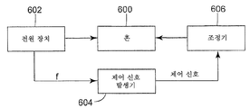
도6은 용접 혼과 앤빌 사이에 실질적으로 일정한 갭을 유지하기 위한 시스템의 예시적인 실시예를 도시한다.6 illustrates an exemplary embodiment of a system for maintaining a substantially constant gap between the weld horn and the anvil.
도7은 초음파 용접 시스템 내의 혼과 앤빌 사이의 갭을 조정하기 위한 시스 템의 예시적인 실시예를 도시한다.7 shows an exemplary embodiment of a system for adjusting the gap between horn and anvil in an ultrasonic welding system.
도8A는 초음파 용접 시스템 내의 혼과 앤빌 사이에 실질적으로 일정한 갭을 유지하기 위한 시스템의 예시적인 실시예를 도시한다.8A shows an exemplary embodiment of a system for maintaining a substantially constant gap between horn and anvil in an ultrasonic welding system.
도8B는 초음파 용접 시스템 내의 혼과 앤빌 사이에 실질적으로 일정한 갭을 유지하기 위한 시스템의 다른 예시적인 실시예를 도시한다.8B shows another exemplary embodiment of a system for maintaining a substantially constant gap between horn and anvil in an ultrasonic welding system.
도9A는 힘 결정 유닛의 예시적인 실시예를 도시한다.9A shows an exemplary embodiment of a force determining unit.
도9B는 힘 결정 유닛의 다른 예시적인 실시예를 도시한다.9B shows another exemplary embodiment of a force determining unit.
도10은 초음파 용접 시스템 내의 혼과 앤빌 사이의 갭을 조정하기 위한 시스템의 예시적인 실시예를 도시한다.10 shows an exemplary embodiment of a system for adjusting the gap between horn and anvil in an ultrasonic welding system.
도11A는 혼의 종축을 따라 전파되는 음파 신호에 의해 구동되는 혼의 표면을 도시한다.11A shows the surface of a horn driven by sound wave signals propagating along the longitudinal axis of the horn.
도11B는 신호가 혼의 종축을 따라 전파될 때, 도11A의 음파 신호보다 더 작은 크기의 음파 신호에 의해 구동되는 혼의 표면을 도시한다.FIG. 11B shows the surface of the horn driven by a sonic signal of a smaller magnitude than the sonic signal of FIG. 11A when the signal propagates along the longitudinal axis of the horn.
도12A는 혼과 앤빌 사이의 갭을 제어하기 위한 시스템의 예시적인 실시예를 도시한다.12A shows an exemplary embodiment of a system for controlling the gap between horns and anvils.
도12B는 혼과 앤빌 사이의 갭을 제어하기 위한 시스템의 다른 예시적인 실시예를 도시한다.12B shows another exemplary embodiment of a system for controlling the gap between horns and anvils.
도13은 조정기 및 진폭 결정 모듈의 작동을 조합하기 위한 방법의 예시적인 실시예를 도시한다.Figure 13 shows an exemplary embodiment of a method for combining the operation of a regulator and an amplitude determination module.
도14는 조정기 및 진폭 결정 모듈의 작동을 조합하기 위한 방법의 다른 예시 적인 실시예를 도시한다.14 shows another exemplary embodiment of a method for combining the operation of a regulator and an amplitude determination module.
본 발명의 다양한 실시예가 유사한 도면 부호가 여러 도면에 걸쳐 유사한 부품 및 조립체를 표시하는 도면을 참조하여 상세하게 설명될 것이다. 다양한 실시예에 대한 참조는 첨부된 청구범위의 범주에 의해서만 제한되는 본 발명의 범주를 제한하지 않는다. 추가적으로, 본 명세서에서 설명되는 모든 예는 제한적으로 의도되지 않고, 단지 청구된 발명에 대한 많은 가능한 실시예 중 일부를 설명한다.Various embodiments of the present invention will be described in detail with reference to the drawings in which like reference numerals indicate like parts and assemblies throughout the several views. Reference to various embodiments does not limit the scope of the invention, which is limited only by the scope of the appended claims. In addition, all examples described herein are not intended to be limiting, but merely describe some of the many possible embodiments for the claimed invention.
도1은 AC 전기 에너지 공급원(102)에 결합된 단순 혼 스택(100)의 일례를 도시한다. 도1로부터 알 수 있는 바와 같이, 혼 스택(100)은 컨버터(104), 부스터(106), 및 초음파 용접 혼(108)을 포함한다. 작동 중에, AC 공급원은 전기 에너지를 컨버터(104)에 공급하고, 컨버터는 AC 신호와 동일한 진동수로 압축 및 팽창함으로써 그에 대해 응답한다. 그러므로, 음파는 컨버터(104)를 통해 부스터(106)로 이동한다. 음파 파면이 부스터(106)를 통해 전파될 때, 이는 증폭되어 용접 혼(108)에 의해 수신된다. (몇몇 실시예에서, 혼(108)은 게인을 달성하도록 설계되어, 부스터(106)에 대한 필요를 제거한다). 마지막으로, 파면은 혼(108)을 통해 전파되고, 이 때 이는 용접 혼(108)과 앤빌(110) 사이에 위치된 (도1에 도시되지 않은) 작업편에 부가된다. 혼 스택의 다른 예가 기술 분야에 공지되어 있고, 본 명세서에서 설명되는 다음의 시스템, 계획, 및 방법에 의해 기능한다.1 shows an example of a
혼(108)은 도1에서 "갭"으로 표시된 거리에 의해 앤빌(110)로부터 분리된다. 작업편에 마찰 에너지를 부가하는 공정은 혼 스택(100)의 다양한 요소들이 온도가 상승하게 한다. 혼 스택(100)의 요소들이 온도가 상승함에 따라, 이들은 열 팽창을 나타내고, 이는 혼(108)과 앤빌(110) 사이의 갭이 혼 스택(100)이 장착된 특정 방식에 따라, 치수가 변하기 쉽다는 것을 의미한다.
도2는 도1의 혼 스택(100)의 단순화된 예시적인 장착 계획을 도시한다. 장착 계획은 강성의 대체로 3부분인 프레임(200)을 사용한다. 프레임(200)은 앤빌(110)이 장착되는 제1 부분(202)과, 혼 스택(100) 상의 노드점에 접한 제2 부분(206)을 포함한다. 예를 들어, 프레임의 제2 부분(206)은 도2에서 부스터(106)의 중간점(208)에 결합된 것으로 도시되어 있다. 프레임(200)의 제3 부분(204)은 제1 및 제2 부분(202, 206)들 사이에서 연장된다.FIG. 2 shows a simplified exemplary mounting scheme of the
장착 시스템(200)은 앤빌(110)의 작업편 지지 표면(210)과 혼 스택(100)의 일 부분 사이에 실질적으로 고정된 거리를 유지한다. 이러한 경우에, 장착 시스템(200)은 앤빌(110)의 상부 표면(210)과 부스터(106)의 중간점/노드점(208) 사이에 실질적으로 고정된 거리를 유지한다. 그러므로, 혼 스택(100)이 작동 중에 팽창하면, 혼 스택(100)은 도2에서 "팽창"으로 표시된 화살표에 의해 표시된 바와 같이, 스택(100)의 종축을 따라, 부스터(106)의 중간점(208)으로부터 외측으로 팽창한다. 다양한 다른 장착 시스템이 또한 앤빌(110)의 상부 표면(210)과 혼 스택(100)의 일 부분 사이에 실질적으로 고정된 거리를 유지할 수 있고, 그러한 다른 장착 시스템은 본 출원의 범주 내에 있다는 것이 이해되어야 한다.The mounting
도2의 장착 배열이 주어지면, 컨버터(104) 및 부스터(106) 상부의 열 팽창은 갭 길이에 대해 영향을 주지 않는다 (프레임(200)이 스택(100)과 결합하는 지 점(208)에 대한 이러한 요소들의 위치 때문에, 이러한 요소들은 상방으로, 즉 앤빌(110)로부터 멀리 자유롭게 팽창한다). 다른 한편으로, 갭 길이는 부스터(106) 하부의 팽창 및 혼(108)의 팽창에 의해 영향을 받고, 이러한 요소들이 팽창함에 따라, 이들은 앤빌(110)을 향해 팽창하고, 갭은 축소된다.Given the mounting arrangement of FIG. 2, thermal expansion above the
일 실시예에 따르면, 컨버터(104) 및 부스터(106)는 실질적으로 일정한 온도로 유지된다. 예를 들어, 컨버터(104) 및 부스터(106)는 컨버터(104) 및 부스터(106)의 표면으로 비교적 차가운 공기를 순환시키는 하나 이상의 팬에 의한 것과 같은 냉각 시스템에 의해 냉각될 수 있어서, 이들의 온도를 실질적으로 유지하고, 이들의 열 팽창을 실질적으로 억제한다. 그러므로, 그러한 실시예에 따르면, 혼 스택(100)의 길이의 임의의 변화는 실질적으로 용접 혼(108)의 팽창에 기인하는 것으로 고려될 수 있다.According to one embodiment,
또한, 몇몇 실시예에 따르면, 혼(108)은 냉각 시스템에 의해 냉각되어, 작동 중에 가열되는 경향을 억제하거나 감소시킨다. 대체로, 그러한 계획은 혼(108)의 열 팽창을 완전히 제거하지는 않고, 이는 그가 여전히 갭 길이가 실질적으로 일정하게 유지되어야 하면 고려되어야 하는 어느 정도의 열 팽창을 나타낸다는 것을 의미한다.In addition, according to some embodiments,
주어진 물체의 길이는 주어진 물체의 공진 진동수에 반비례한다는 것이 공지되어 있다. 달리 말하면, 물체는 길이가 길어짐에 따라, 더 낮은 공진 진동수를 나타낸다. 그러므로, 혼 스택(100)은 예를 들어 열 팽창에 의해 발생하는 바와 같이 길이가 길어짐에 따라, 더 낮은 공진 진동수를 나타낸다. 구체적으로, 물체의 길이(l)는 다음의 방정식에 의해 그의 공진 진동수(f)와 연관된다.It is known that the length of a given object is inversely proportional to the resonant frequency of the given object. In other words, as the length increases, the object exhibits a lower resonant frequency. Hence, the

여기서, E는 대상의 탄성 계수를 표현하고, ρ는 대상의 밀도를 표현한다. 대상이 복합체이면 (예를 들어, 복수의 부분으로 구성되거나 상이한 재료들로부터 만들어진 다양한 구획을 가지면), E 및 ρ는 그의 다양한 부분들을 고려하여, 재료의 거동을 표현하는 할당 값일 수 있다 (예를 들어, 가중 평균 등일 수 있다).Here, E represents the elastic modulus of the object, and ρ represents the density of the object. If the object is a composite (e.g., if it consists of a plurality of parts or has various compartments made from different materials), E and ρ may be assigned values representing the behavior of the material, taking into account its various parts (e.g. For example, a weighted average).
몇몇 실시예에 따르면, 에너지 공급원(102)은 혼 스택(100)의 공진 진동수(f)를 검출하여, 그와 진동수가 동일한 AC 신호를 발생시킨다. 예를 들어, 에너지 공급원(102)은 특정 피크 대 피크 전압 (또는 실효 전압)을 나타내는 사인파 신호를 혼 스택(100)으로 송출할 수 있다. 사인파 신호의 피크 대 피크 (또는 RMS) 전압을 일정하게 유지하면서, 에너지 공급원(102)은 신호의 진동수를 조정하고, 최소 전류가 혼 스택(100)에 의해 흡수되는 진동수를 탐색하고, 이러한 진동수는 혼 스택(100)의 공진 진동수이다. 따라서, 그러한 실시예에 따르면, 스택(100)의 공진 진동수는 에너지 공급원(102)으로부터 얻어질 수 있다. 다른 실시예에 따르면, 스택(100)의 공진 진동수는 검출기에 의한 스택(100)의 관찰에 의해 검출될 수 있다.According to some embodiments,
혼 스택(100)의 공진 진동수를 얻으면, 스택(100)의 전체 길이는 전술한 물리적 원리와 유사한 방식으로, 공진 진동수를 혼 스택 길이와 연관시킴으로써 얻어질 수 있다. 컨버터(104) 및 부스터(106)가 냉각되어, 그에 대한 열 팽창의 효과 를 실질적으로 억제하면, 혼 스택(100)의 길이는 갭 길이와 연관될 수 있다. 예를 들어, 도2의 계획에 따르면, 갭 길이와 혼(108) 길이(L)는 다음의 방정식에 의해 관련된다.Once the resonant frequencies of the
갭 길이 ![]()
![]()
여기서, D는 혼(108)의 상부와 앤빌(110)의 작업편 지지 표면(210) 사이의 길이를 표현하는 대체로 일정한 값이다.Here, D is a generally constant value representing the length between the top of the
도3은 용접 혼(108)과 앤빌(110)의 작업편 지지 표면(210) 사이의 갭의 길이를 결정하기 위한 시스템을 도시한다. 도3의 시스템은 음파 신호를 혼(302) (및 부스터)로 송출하는 초음파 전원 장치(300; 예를 들어, 신호를 음파로 변환하는 컨버터에 AC 신호를 송출하는 전원 장치)를 포함한다. 초음파 전원 장치(300)는 초음파 전원 장치(300)의 작동을 제어하는 펌웨어/소프트웨어를 저장하는 메모리 장치와 데이터 통신하는 프로세서와 같은 제어기 회로에 의해 제어된다. 대안적으로, 제어기 회로는 하드웨어 기반의 제어 루프로서 실시될 수 있다. 각 경우에, 초음파 전원 장치(300)의 제어기는 혼 스택의 공진 진동수를 식별하고, 그와 진동수가 동일한 음파 신호를 발생하기 위해 컨버터와 협동하도록 내부의 전원 장치 신호 발생 회로에 명령한다. 전원 장치(300) 내의 제어기는 갭 결정 유닛(304)과 접속할 수 있다.3 shows a system for determining the length of a gap between the
갭 결정 유닛(304)은 혼 스택의 공진 진동수를 수신하여, 갭 길이에 대해 알려진 관계에 있는 양을 발생시킨다. 일 실시예에 따르면, 갭 결정 유닛(304)은 메모리 유닛에 결합된 프로세서 상에서 실행되는 소프트웨어 모듈이다. 갭 결정 유 닛(304)은 초음파 전원 장치(300)를 제어하는 펌웨어가 실행되는 동일한 프로세서 상에서 실행될 수 있다. 대안적으로, 이는 그와 데이터 통신하는 다른 프로세서 상에서 실행될 수 있다. 각 경우에, 갭 결정 유닛(304)에 의해 실행되는 소프트웨어/펌웨어는 도4A - 도5B를 참조하여 (아래에서) 설명되는 계획에 따라 기능할 수 있다.The
대안적인 실시예에 따르면, 갭 결정 유닛(304)은 초음파 전원 장치(300) 이외의 공급원으로부터 혼 스택의 공진 진동수를 수신할 수 있다. 예를 들어, 시스템은 혼 스택을 관찰하고, 그의 공진 진동수를 측정하고, 공진 진동수를 갭 결정 유닛(304)으로 전달하는 검출기(306)를 포함할 수 있다. 다음의 설명에서, 공진 진동수는 단지 예시적으로 초음파 전원 장치(300)로부터 유래한다고 가정된다.According to an alternative embodiment, the
도4A는 갭 결정 유닛(304)을 작동시킬 수 있는 계획을 도시한다. 갭 결정 유닛(304)은 메모리 장치 내에 저장된 표(400)를 포함할 수 있다. 표(400)는 공진 진동수에 따라 조직될 수 있고, 갭 길이(G)를 공진 진동수(f)와 연관시킨다. 따라서, 공진 진동수(f)를 수신하면, 갭 결정 유닛(304)은 공진 진동수를 사용하여, 표(400)에 엑세스하고 공진 진동수(f)에 대응하는 갭 길이(G)를 결정한다. 예를 들어, 갭 결정 유닛(304)이 입력으로서 f2의 진동수를 수신한다고 가정하면, 유닛(304)은 표(400)에 엑세스하여 진동수(f2)에 대응하는 열을 식별함으로써 응답한다. 열을 식별하면, 그에 입력된 갭 길이(G2)가 반환된다. 선택적으로, 표(400)는 혼 스택(100)의 길이(L)를 결정하거나 갭 길이에 대해 알려진 관계에 있는 임의의 다른 양을 결정하기 위해 엑세스될 수 있다. 갭 결정 유닛(304)이 입력으로서 값(fx)을 수신하고, fx가 연속된 표 입력들 사이에 든다고 (즉, fi < fx < fi +1) 가정하면, 갭 결정 유닛(304)은 갭 길이 값(Gi, Gi +1)을 얻기 위해 표(400)에 엑세스할 수 있고, 공진 진동수(fx)에 대응하는 갭 길이에 도달하기 위해 2개의 값들 사이에서 보간될 수 있다.4A shows a scheme by which
표(400)의 다양한 입력은 표(400) 내에서, 혼 스택(100)의 길이 및 갭의 길이가 각각의 진동수(f)에 대해 기록되는 발견적 과정에 의해 사전에 채워질 수 있다. 대안적으로, 표(400)의 다양한 입력은 전술한 것과 유사한 방식으로, 이론적인 계산에 의해 채워질 수 있다.The various inputs of the table 400 may be prefilled by a heuristic process in which the length of the
도4B는 갭 결정 유닛(304)을 작동시킬 수 있는 다른 계획인, 이론적 계산을 도시한다. 예를 들어, 갭 결정 유닛(304)은 작업(402)에 도시된 바와 같이, 혼 스택(100)의 공진 진동수(f)를 수신함으로써 그의 작동을 시작할 수 있다. 그 후에, 유닛(304)은 작업(404)에 도시된 방정식의 기초가 되는 물리적 원리에 기초한 방정식의 사용에 의한 것과 같이, 공진 진동수에 기초하여, 혼(108)의 길이(L)를 계산함으로써 응답한다. 마지막으로, 작업(406)에 도시된 바와 같이, 유닛(304)은 채용된 장착 계획으로부터 도출된 특정 기하학적 구속의 인지에 기초하여, 작업(404)에서 결정된 길이(L)를 갭 길이와 연관시킬 수 있다. 예를 들어, 도2의 장착 계획의 맥락에서, 갭 길이는 다음과 같이 구해질 수 있다.4B shows a theoretical calculation, another scheme by which
갭 길이 ![]()
![]()
여기서, D는 혼(108)의 상부와 앤빌(110)의 작업편 지지 표면(210) 사이의 거리를 표현하고, L은 혼의 길이를 표현한다.Where D represents the distance between the top of the
도5A는 연속 초음파 용접에 대해 사용되는 용접 혼(500)의 일례를 도시한다. 혼(500)은 혼(500)이 그에 대해 회전할 수 있는 종축(502)을 내부에 포함한다. 혼(500)은 갭이 혼과 앤빌(504) 사이에 유지되도록, (도5A에 도시되지 않은) 장착 시스템에 의해 구속된다. 혼 스택은 시스템 상의 임의의 노드점에 장착될 수 있다. 혼의 종축(502)은 앤빌(504)의 작업편 지지 표면(506)에 대해 실질적으로 평행하다. 또한, 혼은 종축을 갖고, 앤빌은 작업편 지지 표면을 가지며, 혼의 종축은 앤빌의 지지 표면에 대해 실질적으로 직교할 수도 있다.5A shows an example of a
혼 스택의 공진 진동수에 기초하여 혼과 앤빌 사이의 갭의 길이를 결정하는 전술한 원리는 도5의 혼(500)에 적용될 수 있다. 재료는 열 팽창할 때, 모든 방향에서 동일한 비율로 팽창한다. 그러므로, 도5B에 도시된 다음의 기술이 혼과 앤빌 사이의 갭의 길이를 결정하도록 사용될 수 있다.The aforementioned principle of determining the length of the gap between the horn and the anvil based on the resonant frequency of the horn stack can be applied to the
처음에, 작업(508)에 도시된 바와 같이, 혼 스택의 공진 진동수가 수신된다. 그 후에, 혼(502)의 길이(L)는 전술한 바와 같은 방식으로, 진동수에 기초하여 결정된다 (작업 510). 전과 같이, 도5A의 혼 스택은 (도5A에 도시되지 않은) 컨버터 및 (도5A에 도시되지 않은) 부스터가 작동 중에 실질적으로 일정한 온도로 유지되도록 냉각되어, 이들의 열 팽창 및 시스템 공진 진동수에 대한 영향을 억제한다.Initially, as shown in
혼(500)이 모든 치수에서 비례하여 팽창하므로, 그의 길이(L)와 그의 반경 사이의 비율(B)은 일정하게 유지된다. 그러므로, 혼(502)의 길이의 계산 후에, 그의 반경은 작업(512)에 도시된 바와 같이, 길이를 전술한 비율(B)로 곱함으로써 도 달될 수 있다. 마지막으로, 갭의 길이는 작업(514)에 도시된 바와 같이, 혼(500)의 종축과 앤빌(504)의 작업편 지지 표면(506) 사이의 거리(D)에서 반경을 빼서 결정될 수 있다.Since the
도5B에 대해 설명된 방법의 결과는 도4A를 참조하여 설명된 바와 같이, 표 내에 저장될 수 있다는 것을 알아야 한다. 따라서, 갭 길이 또는 그에 대해 알려진 관계에 있는 임의의 값은 혼 스택의 공진 진동수에 기초하여, 그러한 표에 엑세스함으로써 얻어질 수 있다.It should be appreciated that the results of the method described with respect to FIG. 5B may be stored in a table, as described with reference to FIG. 4A. Thus, the gap length or any value with a known relationship to it can be obtained by accessing such a table, based on the resonant frequency of the horn stack.
도6은 혼 스택의 공진 진동수의 관찰에 기초하여, 혼과 앤빌 사이에 실질적으로 일정한 갭을 유지하기 위한 제어 시스템을 도시한다. 시스템은 혼 스택(600)과 그에 결합된 전원 장치(602)를 포함한다. 일 실시예에 따르면, 전원 장치(602)는 전술한 바와 같이, 혼 스택(600)의 공진 진동수를 결정한다.6 shows a control system for maintaining a substantially constant gap between the horn and the anvil, based on the observation of the resonance frequency of the horn stack. The system includes a
위치 조정기(606)가 혼 스택에 결합된다. 위치 조정기(606)는 혼 스택(600)을 입력 신호의 제어 하에서, 앤빌을 향해 또는 그로부터 멀리 조정한다. 조정기(606)로 송출된 입력 신호와 이에 대한 조정기의 응답 사이에 알려진 관계가 존재한다. 위치 조정기(606)는 제어 신호 발생기(604)와 데이터 통신한다. 제어 신호 발생기(604)는 입력으로서 혼 스택의 공진 진동수를 수신하고, 위치 조정기(606)로 송출되는 제어 신호를 발생시킨다. 제어 신호 발생기(604)는 혼 스택(600)의 공진 진동수와, 위치 조정기(606)의 응답과 그의 입력 신호 사이의 관계가 주어지면, 앤빌과 혼 사이에 실질적으로 일정한 갭을 유지하는 제어 신호를 발생한다.
제어 신호 발생기(604)는 전술한 원리에 따른 펌웨어/소프트웨어를 저장하는 메모리 장치와 데이터 통신하는 프로세서와 같은, 제어기 회로로서 실시될 수 있다. 이는 대안적으로 실질적으로 일정한 갭을 유지하기 위한 전술한 제어 신호를 발생하는 ASIC으로서 실시될 수 있다. 개시 내용의 다음 부분에서, 위치 조정기의 특정 실시예가 개시된다. 본 발명의 실시를 위해 후술되는 위치 조정기를 사용하는 것이 필수적이지는 않다. 또한, 명세서의 이전 부분은 혼 스택의 공진 진동수에 기초하여, 혼의 길이 또는 갭의 길이를 결정하는 특정 방법에 관한 것이었다. 다른 실시예에 따르면, 그러한 결정은 혼 스택 또는 그의 다양한 구성요소들의 온도 측정에 의해 도달될 수 있다.The
도7은 혼과 앤빌 사이의 갭을 조정하기 위한 시스템의 예시적인 실시예를 도시한다. 시스템은 앤빌(704)의 작업편 지지 표면(702) 위에 배향된 혼(700)을 내부에 포함한다. 혼(700)은 프레임(706)에 견고하게 결합된다. 프레임(706)은 프레임(706)과 혼(700)이 수직으로 병진 이동할 수 있도록, 수신기(710)와 맞물리는 슬라이드(708)를 포함한다.7 shows an exemplary embodiment of a system for adjusting the gap between horns and anvils. The system includes a
프레임(706)은 한 쌍의 부재(714)에 의해 프레임(706)에 결합된 힘 수신 플레이트(712)를 또한 포함한다. 힘이 (도7에 도시되지 않은) 힘 적용기에 의해 힘 수신 플레이트(712)에 적용된다. 힘은 앤빌(704)을 향해 혼(700)을 압박한다. 힘의 방향은 화살표(713)에 의해 표시되어 있다. 힘은 접촉 표면(716)이 탄성 변형 가능한 멈춤부(718)와 맞닿게 하는 효과를 갖는다. 탄성 변형 가능한 멈춤부(718) 상에 가해진 힘은 멈춤부(718)가 변형되어 하향 휨(즉, 앤빌(704)의 방향으로의 휨)을 나타내게 한다. 대체로, 플레이트(712)에 적용되는 힘이 클 수록, 멈춤부(718)에 의해 나타나는 하향 휨이 더 크다. 멈춤부(718)에 의해 나타나는 휨이 클 수록, 혼(700)과 앤빌(704) 사이의 갭이 더 작다.
혼(700)과 앤빌(704) 사이에 일정한 갭을 유지하기 위해, 다음의 계획이 채용될 수 있다. 혼(700)이 그의 미상승 온도에 있을 때, 초기력이 플레이트(712)에 적용되어, 혼(700)과 앤빌(704) 사이의 갭이 "이상적인" 길이로 확립되게 한다. 혼(700)이 작동 중에 열 팽창함에 따라, 갭은 작아진다. 이러한 효과를 상쇄하기 위해, 플레이트(712)에 적용되는 힘은 감소되어, 멈춤부(718)가 더 적은 휨을 나타내게 하고, 이는 혼(700)과 프레임이 상방으로 (즉, 앤빌로부터 멀리) 병진 이동하는 것을 의미한다. 따라서, 혼(700)과 앤빌(704) 사이의 갭은 플레이트(712)에 대한 제어된 힘의 적용에 의해 실질적으로 일정하게 유지될 수 있다. 이러한 계획의 기능성을 확보하기 위해, 플레이트(712)에 적용되는 초기력은 멈춤부(718)가 적어도 상쇄되어야 하는 예상 열 팽창만큼 휨을 나타내게 하기에 충분한 크기이어야 한다.In order to maintain a constant gap between
변형 가능한 멈춤부(714)는 탄성이고, 양호하게는 비교적 높은 탄성 계수를 갖는다. 비교적 높은 탄성 계수를 갖는 재료의 선택에 의해, 멈춤부(714)를 휘기 위해 요구되는 힘이 공정 힘(즉, 혼에 의해 작업편 상에 가해지는 힘)에 비해 비교적 큰 환경이 설정된다. 그러한 배열은 제어 설계의 용이성을 제공한다. 일 실시예에 따르면, 멈춤부(714)는 강철, 또는 다른 적합한 재료로 제조될 수 있다. 일 실시예에 따르면, 멈춤부(714) 상에 가해지는 힘은 내부의 재료가 그의 탄성 범위 를 넘게 하지 않는다 (즉, 멈춤부(714)는 힘의 제거 시에 그의 원래의 형상으로 복귀할 것이다). 더욱이, 일 실시예에 따르면, 멈춤부(714)는 그에 적용되는 힘에 비례하는 휨을 나타낸다. 즉, 멈춤부(714)에 적용되는 힘과 그에 의해 나타나는 휨의 범위 사이에 선형 관계가 존재한다.Deformable stop 714 is elastic and preferably has a relatively high modulus of elasticity. By the selection of a material having a relatively high modulus of elasticity, an environment is set in which the force required to bend the
도8A는 도7의 예시적인 조정 시스템과 함께 사용하기 위한 제어 시스템의 일례를 도시한다. (후술하는 도8A의 다양한 유닛(804 - 810)은 컴퓨터 판독 가능한 매체 내에 저장되어 프로세서에 의해 실행되는 소프트웨어 모듈로서 실시될 수 있거나, 하나 이상의 주문형 집적 회로 또는 현장 프로그램식 게이트 어레이와 같은 전용 하드웨어로서 실시될 수 있다. 더욱이, 유닛(804 - 810)들은 설계 선택의 이유로 조합되거나 분할될 수 있다.) 도8A로부터 알 수 있는 바와 같이, 시스템은 초음파 전원 장치(802)에 결합된 혼(800)을 포함한다. 갭 결정 유닛(804)이 혼(800)과 (도8에 도시되지 않은) 앤빌 사이의 갭을 결정한다. 일 실시예에 따르면, 갭 결정 유닛(804)은 전원 장치(802)로부터 혼 스택의 공진 진동수를 얻고, 그로부터 갭을 결정한다. 다른 실시예에 따르면, 갭 결정 유닛(804)은 혼의 관찰에 의해 혼(800)의 공진 진동수를 검출한다. 또 다른 실시예에 따르면, 갭 결정 유닛(804)은 혼의 온도를 측정하고, 그로부터 혼 길이를 추정하고, 혼 길이에 기초하여 갭 길이에 도달함으로써, 갭 길이에 도달한다.8A shows an example of a control system for use with the example adjustment system of FIG. 7. (The various units 804-810 of FIG. 8A described below may be implemented as software modules stored in a computer readable medium and executed by a processor, or may be implemented as dedicated hardware such as one or more custom integrated circuits or field programmable gate arrays. Furthermore, the units 804-810 can be combined or split for design choice reasons. As can be seen from Figure 8A, the system is coupled to a
갭 결정 유닛에 의해 도달된 갭 길이는 힘 결정 유닛(806)으로 공급된다. 힘 결정 유닛(806)은 갭을 실질적으로 일정한 길이로 유지하기 위해, 프레임(예를 들어, 도7의 플레이트(712)) 상에 가해지는 힘을 결정한다. 갭 결정 유닛(806)에 의해 도달된 힘은 제어 신호 발생기(808)로 공급된다. 제어 신호 발생기(808)는 제어 신호를 발현하고, 그러한 제어 신호를 힘 적용기(810)로 전달한다. 힘 적용기(810)는 수신된 제어 신호와 그가 가하는 힘 사이의 알려진 관계를 나타낸다. 따라서, 제어 신호 발생기(808)는 그러한 관계에 비추어 제어 신호를 발현한다.The gap length reached by the gap determination unit is supplied to the
도8B는 갭 결정 유닛(804) 및 힘 결정 유닛(806)의 예시적인 실시예를 도시한다. (도8A의 유닛의 경우에서와 같이, 후술되는 도8B의 다양한 유닛은 컴퓨터 판독 가능한 매체 내에 저장되어 프로세서에 의해 실행되는 소프트웨어 모듈로서 실시될 수 있거나, 하나 이상의 주문형 집적 회로 또는 현장 프로그램식 게이트 어레이와 같은 전용 하드웨어로서 실시될 수 있다. 더욱이, 도8B의 유닛들은 설계 선택의 이유로 조합되거나 분할될 수 있다.) 도8B로부터 알 수 있는 바와 같이, 갭 결정 유닛(804)은 길이 결정 유닛(812) 및 갭 탐색 유닛(814)을 포함한다. 길이 결정 유닛(812)은 혼 스택의 공진 진동수를 수신하고, 혼의 길이를 탐색하기 위해 도4A 및 도4B를 참조하여 설명된 방법들 중 하나를 적용한다. 그 후에, 혼의 길이는 갭 탐색 유닛(814)에 의해 수신된다. 갭 탐색 유닛(814)은 혼의 길이의 인지, 및 장착 계획에 의해 부가되는 특정 기하학적 특징에 의해 갭 길이에 도달한다 (예를 들어, 갭 길이는 혼의 상부로부터 작업편 지지 표면으로의 길이와 혼 길이 사이의 차이와 동일할 수 있다, 갭 = D - L).8B shows an exemplary embodiment of a
갭 길이에 도달한 후에, 이러한 값은 힘 결정 유닛(806)에 제공된다. 힘 결정 유닛(806)은 갭을 실질적으로 일정하게 유지하기 위해, 프레임에 적용되는 힘에 도달한다. 도달된 힘은 무엇보다도, 멈춤부의 길이(Lstop), 멈춤부의 탄성 계수(E), 멈춤부의 단면적(A), 초기 갭 길이와 갭 결정 유닛(804)에 의해 도달된 갭 길이 사이의 차이(Δ), 및 조립된 시스템 휨의 함수이다.After reaching the gap length, this value is provided to the
도9A는 힘 결정 유닛(806)을 작동시킬 수 있는 계획을 도시한다. 힘 결정 유닛(806)은 메모리 장치 내에 저장된 표(900)를 포함할 수 있다. 표(900)는 공진 갭 길이(G)에 따라 조직되고, 힘(F)을 갭 길이(G)와 연관시킨다. 따라서, 갭 길이(G)를 수신하면, 힘 결정 유닛(806)은 갭 길이를 사용하여, 표(900)에 엑세스하고 갭 길이(G)에 대응하는 힘(F)을 결정한다. 예를 들어, 힘 결정 유닛(806)이 입력으로서 G2의 갭 길이를 수신한다고 가정하면, 유닛(806)은 갭 길이(G2)에 대응하는 열을 식별하기 위해 표(900)에 엑세스함으로써 응답한다. 열의 식별 시에, 그에 입력된 힘(F2)이 반환된다. 선택적으로, 표(900)는 힘 적용기(810)로 송출되는 제어 신호(C)를 결정하거나 프레임 상에 가해지는 힘에 대해 알려진 관계에 있는 임의의 다른 양을 결정하기 위해 엑세스될 수 있다. 힘 결정 유닛(806)이 입력으로서 값(Gx)을 수신하고, Gx가 연속된 표 입력들 사이에 든다고 (즉, Gi < Gx < Gi +1) 가정하면, 힘 결정 유닛(806)은 힘 값(Fi, Fi +1)을 얻기 위해 표(900)에 엑세스할 수 있고, 갭 길이(Gx)에 대응하는 힘에 도달하기 위해 2개의 값들 사이에서 보간될 수 있다.9A shows a scheme by which the
표(900)의 다양한 입력은 표(900) 내에서, 프레임에 적용되는 힘과 그에 대 응하는 제어 신호가 각각의 갭 길이(G)에 대해 실험적으로 결정되는 발견적 과정에 의해 사전에 채워질 수 있다. 대안적으로, 표(900)의 다양한 입력은 도9B를 참조하여 후술하는 것과 유사한 방식으로, 이론적인 계산에 의해 채워질 수 있다.The various inputs of the table 900 can be pre-filled within the table 900 by a heuristic process in which the force applied to the frame and the corresponding control signals are determined experimentally for each gap length G. have. Alternatively, various inputs of table 900 may be filled by theoretical calculations, in a manner similar to that described below with reference to FIG. 9B.
도9B는 힘 결정 유닛(806)을 작동시킬 수 있는 다른 계획인, 이론적 계산을 도시한다. 예를 들어, 힘 결정 유닛(806)은 작업(902)에 도시된 바와 같이, 갭 결정 유닛(804)에 의해 계산된 갭 길이(CG)를 수신함으로써 그의 작동을 시작할 수 있다. 그 후에, 유닛(806)은 작업(904)에 도시된 바와 같이, 초기 갭(IG)과 계산된 갭(CG) 사이의 차이를 계산함으로써 응답한다. 이러한 차이(Δ)는 멈춤부의 휨이 갭을 그의 초기 길이로 복귀시키기 위해 감소되어야 하는 양을 말한다. 따라서, 작업(906)에서, 프레임에 적용되는 새로운 힘(Fnew)이 그에 도시된 방정식의 Fnew에 대해 풀어서 도달될 수 있다.9B shows a theoretical calculation, another scheme by which
도10은 혼과 앤빌 사이의 갭을 조정하기 위한 시스템의 다른 예시적인 실시예를 도시한다. 용접 시스템(1010)은 지지 표면(1017)에 고정된 용접 시스템(1030)과, 지지 표면(1018)에 고정된 앤빌(1021)을 갖는다. 용접 시스템(1030)은 혼 지지부(1020)에 의해 지지되며 표면(1017)에 대해 이동 가능한 혼(1032)과, 표면(1017)에 대해 고정된, 지지 플레이트(1056)를 갖는 고정 멈춤부(1055)와, 팽창 가능한 공압 블래더(1061)를 포함한다.10 illustrates another exemplary embodiment of a system for adjusting the gap between horns and anvils. The
블래더(1061)는 앤빌(1021)을 향해 혼 지지부(1020) 및 혼(1032)을 이동시키기 위한 힘을 적용하도록 사용되고, 힘은 블래더(1061) 내의 공기 압력을 조정함으 로써 제어된다. 표면(1025)이 고정 멈춤부(1055)와 접촉하면, 지지 플레이트(1056)는 적용된 힘 하에서 약간 휜다.
하나의 구체적인 예에서, 원하는 제품을 용접하기 위한 최소의 허용 가능한 힘은 블래더(161) 내의 30 psig(약 207 kPa)의 공기 압력에 의해 발생되는 600 파운드(약 272 kg)이다. 원하는 고정 갭은 0.0020 인치(약 0.05 mm)이다.In one specific example, the minimum allowable force for welding the desired product is 600 pounds (about 272 kg) generated by 30 psig (about 207 kPa) air pressure in the bladder 161. The desired fixed gap is 0.0020 inches (about 0.05 mm).
티타늄 혼에 의한 작업 시에, 온도는 최대 50℉(약 27.7℃)만큼 실온으로부터 증가할 것이고, 이는 혼 길이를 0.0010 인치(약 0.025 mm)만큼 증가시킬 것으로 결정되었다. 결과적으로, 혼(132)과 앤빌(121) 사이의 갭은 보상이 이루어지지 않으면, 0.0010 인치(약 0.025 mm)로 감소된다. 지지 플레이트(156)의 휨은 675 파운드 힘(약 306 kg-force)당 0.0010 인치(약 0.025 mm)로 공지되어 있다. 그러므로, 실온의 혼에서 적용되는 힘은 적어도 1125 파운드(약 510 kg), 또는 60 psig(약 414 kPa)이어야 한다. 혼이 작동하여 길이가 증가함에 따라, 적용되는 공기 압력은 혼과 앤빌 사이의 갭을 일정하게 유지하기 위해 60 psig(약 414 kPa)로부터 30 psig(약 207 kPa)로 감소된다.In operation with a titanium horn, the temperature will increase from room temperature by up to 50 ° F. (about 27.7 ° C.), which was determined to increase the horn length by 0.0010 inches (about 0.025 mm). As a result, the gap between horn 132 and anvil 121 is reduced to 0.0010 inches (about 0.025 mm) if no compensation is made. The bending of the support plate 156 is known at 0.0010 inches (about 0.025 mm) per 675 pound force (about 306 kg-force). Therefore, the force applied at the horn at room temperature should be at least 1125 pounds (about 510 kg), or 60 psig (about 414 kPa). As the horn operates to increase its length, the applied air pressure decreases from 60 psig (about 414 kPa) to 30 psig (about 207 kPa) to maintain a constant gap between the horn and the anvil.
대체로 변형 가능한 멈춤 조립체를 이용함으로써 앤빌과 혼 사이의 거리를 제어하도록 구성된 용접 장치는 고정 멈춤부를 갖는 앤빌과, 혼과, 고정 멈춤부의 탄성 변형이 혼과 앤빌 사이의 갭에 대한 미세 제어를 제공하도록 고정 멈춤부에 대해 혼을 가압하기 위해 힘을 적용할 수 있도록 장착된 힘 적용기를 포함한다. 장치는 혼과 앤빌 사이의 갭을 비특성의 변화에도 불구하고 고정된 값으로 유지하기 위해, 혼의 비특성을 모니터링하고 혼에 적용되는 힘을 제어하기 위한 감지 시 스템을 포함할 수 있다. 모니터링되는 특성은 예를 들어 혼의 온도, 길이, 또는 진동수일 수 있다.The welding device configured to control the distance between the anvil and the horn by using a generally deformable stop assembly is such that the anvil with the fixed stop and the elastic deformation of the horn and the fixed stop provide fine control over the gap between the horn and the anvil. And a force applicator mounted to apply force to press the horn against the stationary stop. The device may include a sensing system for monitoring the specific properties of the horn and controlling the force applied to the horn to maintain the gap between the horn and the anvil at a fixed value despite the change in specific properties. The property to be monitored can be, for example, the temperature, length, or frequency of the horn.
열 팽창으로 인한 혼 길이 증가를 보상하기 위해 변형 가능하지만 고정된 멈춤부를 사용하는 것은 회전식 앤빌, 고정식 앤빌, 회전식 혼, 고정식 혼, 또는 이들의 임의의 조합에서 사용될 수 있다.Using a deformable but fixed stop to compensate for horn length increase due to thermal expansion can be used in rotary anvils, fixed anvils, rotary horns, fixed horns, or any combination thereof.
사용 시에, 결합되는 작업편은 혼과 앤빌 사이에 위치되고, 에너지가 혼에 적용되어 혼이 급전되고, 고정 멈춤부의 탄성 변형이 혼과 앤빌 사이의 갭의 미세 제어를 제공하도록 고정 멈춤부에 대해 혼을 압박하도록, 힘이 혼에 적용된다.In use, the workpiece to be joined is located between the horn and the anvil, energy is applied to the horn to feed the horn, and the elastic deformation of the fixed stop provides a fine control of the gap between the horn and the anvil. Force is applied to the horn to squeeze it against it.
전술한 방법을 채용하기 위해, 시스템에 대한 데이터를 결정하고, 그 다음 이를 특정 유닛에 대한 제어 시스템 내에서 사용될 수 있는 방정식에 대입할 수 있다. 출원인은 전술한 시스템에 대해 다음의 방법을 사용했지만, 이러한 방법은 상이한 구성의 다른 시스템에 적용될 수 있다. 방정식은 공학적 원리를 사용하여 또는 개별 시스템으로부터 측정된 데이터를 사용하여 도출될 수 있다.To employ the method described above, one can determine the data for the system and then substitute it into equations that can be used within the control system for the particular unit. Applicant used the following method for the above-described system, but this method can be applied to other systems of different configurations. Equations can be derived using engineering principles or using data measured from individual systems.
방정식 2 - 5는 2개의 변수의 선형 시스템에 가장 잘 맞춰졌다. 방정식의 기울기 및 절편은 시스템의 가장 잘 맞춰진 측정 데이터로부터 실험적으로 결정되었다. 변수들 사이의 관계를 측정하는 것은 유사하게 임의의 특정 시스템의 기울기 및 절편을 산출할 수 있다. 시스템이 작동 영역 내에서 선형으로 거동하는 것이 양호하지만, 시스템이 비선형이면, 2차 이상의 방정식이 사용될 수 있다.Equations 2-5 best fit the linear system of two variables. The slope and intercept of the equation were determined experimentally from the best fitted measurement data of the system. Measuring the relationship between the variables can similarly yield the slope and intercept of any particular system. It is preferable that the system behaves linearly within the operating area, but if the system is nonlinear, then quadratic or higher equations can be used.
출원인은 초음파 용접 중의 갭 제어를 위해 후술하는 방법을 개발하여 사용했다.Applicants developed and used the method described below for gap control during ultrasonic welding.
먼저, 전술한 바와 같은 회전식 초음파 시스템에 대해, 다음의 파라미터가 결정되었다.First, for the rotary ultrasound system as described above, the following parameters were determined.
(1) 혼 직경 = 6.880"(1) Horn Diameter = 6.880 "
(2) 주위 온도 = 65℉(2) ambient temperature = 65 ° F
(3) 주위 온도에서의 진동수 = 19.986 KHz(3) Frequency at ambient temperature = 19.986 KHz
(4) 갭이 설정된 압력 = 72.5 psig(4) gapped pressure = 72.5 psig
(5) 공정에 대한 갭 설정점 = 2 mil(1 mil = 0.001 인치)(5) Gap Set Point for Process = 2 mils (1 mil = 0.001 inch)
혼의 재료 특성도 공지되어 있다.The material properties of the horn are also known.
(6) 열 팽창 계수(α)(6) coefficient of thermal expansion (α)
αTitanium = 5.4×10⁻⁶ ℉/inch/inchα Titanium = 5.4 × 10 -6 ℉ / inch / inch
αAluminum = 5.4×10⁻⁵ ℉/inch/inchα Aluminum = 5.4 × 10 -5 ℉ / inch / inch
시스템이 급전되어 작동할 때, 혼은 온도가 증가할 것이다. 다음으로, 연속 용접 시에 갭이 남지 않는 온도(Tfinal)를 결정한다 (즉, 2.0 mil 갭이 0으로 되어, 예를 들어 혼과 앤빌 사이에 접촉이 있음). 이러한 온도는 방정식 1을 풀어서 구해진다.When the system is powered up and running, the horn will increase in temperature. Next, the temperature T final at which the gap does not remain during continuous welding is determined (ie the 2.0 mil gap is zero, for example there is contact between the horn and the anvil). This temperature is obtained by solving

방정식 1에서, Tfinal은 갭이 사라지는 온도이고, IG는 시스템이 설치되고 작동되지 않을 때 설정되고 측정된 (mil 단위의) 초기 갭이고, D는 회전식 혼의 외경이고, α는 혼 재료의 열 팽창 계수이다. 알루미늄 혼에 대한 상기 입력을 사용하여 방정식 1을 푸는 것은 작동 중의 혼의 가열에 기초하여 갭이 0이 되는 172.7℉의 온도를 제공한다. 따라서, 혼이 172.67℉로 가열되면, 갭이 남지 않을 것이다. 따라서, 온도에 대한 상한이 있다. 임의의 주어진 시스템에 대한 상한은 회전식 시스템에 대해 방정식 1을 사용하여 구해질 수 있다. 당업자는 또한 유사한 방정식이 다른 기하학적 특징에 대해 도출될 수 있으며, 갭이 사라지는 것을 방지하기 위한 상한 작동 온도가 결정될 수 있다는 것을 이해할 것이다.In
혼의 동적 공진 상태에 대한 온도를 측정하는 것이 어려우므로, 출원인은 간접적이지만 정확한 온도 측정을 제공하는 대안을 사용하는 것을 개발했다. 온도를 직접 측정하는 대신에, 혼의 진동수는 작동 중에 혼의 진동수를 측정한 다음 아래의 방정식 2를 사용하여 온도를 결정함으로써 결정된다.Since it is difficult to measure the temperature for the dynamic resonance state of the horn, Applicants have developed an alternative that provides an indirect but accurate temperature measurement. Instead of measuring the temperature directly, the horn frequency is determined by measuring the horn frequency during operation and then determining the temperature using Equation 2 below.
방정식 2에서, λmin은 갭이 0이 되기 전에 혼이 작동될 수 있는 최소 진동수이고, 선형 방정식의 계수들은 실험에 의해 실험적으로 결정되었다. 입력 파라미터에 대해 방정식 2를 풀면, 갭은 혼의 진동수가 19,802 Hz 미만으로 떨어질 때, 0이 될 것이다. 혼의 진동수가 당업자에 의해 일반적으로 사용되는 표준 장비를 사 용하여 쉽게 측정될 수 있는 파라미터이므로, 방정식 1 및 2를 사용하여, 제품 손상을 일으키고 또한 접촉으로 인해 혼 및/또는 앤빌을 손상시킬 수 있는 갭 폐쇄를 방지하는 회전식 시스템의 최소 작동 진동수를 결정할 수 있다.In Equation 2, λ min is the minimum frequency at which the horn can be operated before the gap becomes zero, and the coefficients of the linear equation have been determined experimentally by experiment. Solving Equation 2 for the input parameters, the gap will be zero when the horn frequency drops below 19,802 Hz. Since the frequency of the horn is a parameter that can be easily measured using standard equipment commonly used by one of ordinary skill in the art, using
방정식 1 및 2를 사용하여, 이제 갭을 온도와 그리고 온도를 진동수와 연관시키는 능력을 갖는다. 따라서, 갭을 진동수와 연관시킬 수 있다. 정상 작동 중에, 재료가 갭 (또는 닙) 내에 있을 때, 갭을 측정하는 것은 어렵지만, 상기 원리를 사용하여, 진동수가 갭을 결정하기 위해 사용될 수 있다. 혼의 진동수와 혼과 앤빌 사이의 갭 사이의 관계는 다음의 (진동수의 함수로서 갭에 대해 풀 수 있거나 그 반대도 가능한) 방정식 3을 사용하여 결정될 수 있다.Using
방정식 3에서, λ는 혼 진동수이고, Gap은 mil(1 mil = 0.001 인치) 단위로 측정된다. 1 mil의 갭에 대해 방정식 3을 푸는 것은 19,889 Hz의 진동수를 제공한다. 이제 진동수의 함수로서 갭 변화를 결정하는 방법이 있다는 것을 알아야 한다. 방정식 1 - 3에 의해 이렇게 결정된 정보를 사용하여, 혼/앤빌 배열에 적용되는 힘은 혼의 온도 및 진동수가 용접 조립체의 작동 중에 변화할 때 작동 갭을 일정하게 유지하도록 제어될 수 있다.In Equation 3, λ is the horn frequency and Gap is measured in mils (1 mil = 0.001 inch). Solving equation 3 for a gap of 1 mil gives a frequency of 19,889 Hz. Now we need to know that there is a way to determine the gap change as a function of frequency. Using the information thus determined by equations 1-3, the force applied to the horn / anvil arrangement can be controlled to keep the working gap constant when the temperature and frequency of the horn change during operation of the weld assembly.
갭을 제어하고 일정한 작동 값으로 유지하기 위해, 시스템에 적용되는 압력은 제어되어, 작동 중에 가열되는 혼의 열 팽창을 보상한다. 다시 상기 예를 참조하면, 갭이 1 mil로 감소될 때, 시스템이 2 mil의 초기 갭 설정을 유지하거나 그로 복귀될 수 있도록 시스템 상에 가해지는 압력을 감소시킬 필요가 있다. 따라서, 열 팽창을 보상하기 위해, 압력은 갭을 2 mil로 복귀시키도록 감소된다.In order to control the gap and maintain a constant operating value, the pressure applied to the system is controlled to compensate for the thermal expansion of the horn heated during operation. Referring back to the example above, when the gap is reduced to 1 mil, it is necessary to reduce the pressure applied on the system so that the system can maintain or return to the initial gap setting of 2 mils. Thus, to compensate for thermal expansion, the pressure is reduced to return the gap to 2 mils.
압력을 적절하게 감소시키기 위해, 먼저 다음의 방정식 4에 의해 도시된 바와 같이, 압력과 진동수 사이의 관계를 결정할 필요가 있다.In order to appropriately reduce the pressure, it is first necessary to determine the relationship between the pressure and the frequency, as shown by the following equation (4).
여기서, Pcompensation은 시스템 상에서의 (평방 인치당 파운드 단위의) 압력 감소이고, λ는 방정식 3으로부터 결정된 진동수이고, Psetpoint는 초기 갭 설정점에서의 압력이다.Where P compensation is the pressure drop (in pounds per square inch) on the system, λ is the frequency determined from Equation 3, and P setpoint is the pressure at the initial gap set point.
예를 들어, 상기 파라미터를 사용하여, 혼이 열 팽창으로 인해 1 mil 팽창할 때, 2 mil의 초기 갭을 이동 복원하기 위해 필요한 압력 감소를 결정할 수 있다.For example, using the above parameters, when the horn expands 1 mil due to thermal expansion, it is possible to determine the pressure drop needed to shift back the initial gap of 2 mils.
예: 갭이 1 mil로 변화되면 필요한 압력 보상은? Example: What pressure compensation is required if the gap changes to 1 mil?
먼저, 방정식 3으로부터 1 mil에서의 갭에 대한 진동수를 계산한다 (앞서 결정된 바와 같이, 그러한 값은 19.889 Hz임). 그 다음 값을 방정식 4로 대입하여 다음을 산출한다.First, calculate the frequency for the gap at 1 mil from equation 3 (as determined previously, such value is 19.889 Hz). Then substitute the value into Equation 4 to yield
Pcompensation = -367.3404(19.889) + 7412.7731 - 72.5P compensation = -367.3404 (19.889) + 7412.7731-72.5
= 106.7399 - 72.5= 106.7399-72.5
Pcompensation = 34.24 psig (작동 압력의 감소)P compensation = 34.24 psig (reduction of working pressure)
압력이 결정된 후에, 열 팽창을 보상하기 위해, 그러한 압력 보상에서의 갭이 확인될 수 있다. 이러한 갭은 초기 갭에 열 팽창으로 인한 갭 변화를 더한 것과 대체로 동일해야 한다. 확인을 위해, 먼저 압력과 갭 사이의 관계가 다음의 방정식 5에 의해 결정된다.After the pressure is determined, a gap in such pressure compensation can be identified to compensate for thermal expansion. This gap should be approximately equal to the initial gap plus the gap change due to thermal expansion. For confirmation, first the relationship between pressure and gap is determined by the following equation.
예를 들어, (방정식 4로부터의) 34.24 psig의 압력 보상에서, 방정식 5를 재배열하여 갭에 대해 풀 수 있다.For example, at a pressure compensation of 34.24 psig (from equation 4), equation 5 can be rearranged to solve for the gap.
압력 보상에서의 갭 = (34.24 - 142.205)/-35.461 = 3.045 milGap in pressure compensation = (34.24-142.205) /-35.461 = 3.045 mil
따라서, 초기 갭이 2.0 mil로 설정되었고 갭 변화가 1 mil이었기 때문에, 모델을 평가할 수 있다. 그러므로, 작동 중의 혼의 가열로 인한 1 mil 팽창을 보상하기 위해, 갭을 1 mil만큼 개방하여 원래의 2.0 mil 갭을 복원한다.Thus, since the initial gap was set to 2.0 mils and the gap change was 1 mil, the model can be evaluated. Therefore, to compensate for 1 mil expansion due to heating of the horn during operation, open the gap by 1 mil to restore the original 2.0 mil gap.
따라서, 작동 파라미터를 결정하기 위해 전술한 방정식을 사용하거나 (선형 혼 또는 다른 기하학적 특징에 대한 등가물을 도출하여), 회전식 초음파 용접 공정에 대한 작동 한계를 결정할 수 있다. 예를 들어, 작동 온도 한계는 방정식 1 및 갭 설정점(목표)의 값을 사용하여 구해진다. 초음파 혼의 작동 진동수 한계는 방정식 2를 사용하고 방정식 1로부터의 온도 한계의 값을 사용하여 구해진다. 갭 변화 시의 진동수는 방정식 3을 사용하고 입력으로서 갭의 값을 사용하여 구해진다. 갭 변화 시의 온도는 방정식 2를 사용하지만, 방정식 3으로부터 결정된 진동수의 값을 사용하여 구해진다. 갭 변화에 대한 압력 보상은 방정식 4를 사용하지만 방정식 3으로부터의 진동수의 값을 사용하여 구해진다. 압력 보상(주위 온도)에서의 갭은 방정식 5를 사용하지만 방정식 4로부터의 압력 보상의 값을 사용하여 구해진다.Thus, the above-described equations can be used to determine operating parameters (by deriving equivalents to linear horns or other geometrical features) or the operating limits for a rotary ultrasonic welding process can be determined. For example, the operating temperature limit is obtained using the value of
혼과 앤빌 사이의 갭을 제어할 수 있는 또 다른 계획이 존재한다. 전술한 바와 같이, 초음파 용접의 맥락에서, 혼은 대체로 20,000 내지 40,000 Hz의 범위 내의 음파 신호에 의해 구동된다. 도11A는 음파가 혼의 종축을 따라 전파될 때의 혼의 표면(110)을 도시한다. 음파의 전파 방향은 화살표(1102)에 의해 도시되어 있다. 도11A로부터 알 수 있는 바와 같이, 음파가 혼의 종축을 따라 전파될 때, 혼의 표면(1100)은 섭동되고, 그에 대한 정상파형(1104)을 나타낸다. 정상파형(1104)은 혼 표면에 의해 나타나는 "변위"로 불리는 피크 대 피크 진폭을 나타낸다. 피크 대 피크 진폭, 또는 표면 변위는 혼을 따라 전파되는 음파 신호의 진폭의 함수이다. 당연히, 음파 신호의 진폭은 혼에 결합된 컨버터에 공급되는 전기 신호의 진폭의 함수이다. 따라서, 혼의 표면(1100)에 의해 나타나는 변위는 컨버터로 송출되는 전기 신호의 진폭의 함수이다. 전형적으로, 컨버터로 송출되는 전기 신호의 진폭이 클 수록, 혼을 따라 전파되는 음파 신호의 진폭이 더 크고, 음파 신호의 진폭이 클 수록, 혼의 표면(1100)에 의해 나타내는 변위가 더 크다.There is another plan to control the gap between the horn and the anvil. As mentioned above, in the context of ultrasonic welding, the horn is driven by sound wave signals in the range of approximately 20,000 to 40,000 Hz. 11A shows the
도11A로부터 알 수 있는 바와 같이, 혼의 표면(1100)과 앤빌의 표면(1106) 사이의 갭은 변위의 함수이다. 혼이 더 큰 표면 변위를 나타내면, 혼의 표면과 앤빌의 표면 사이의 갭은 감소한다.As can be seen from FIG. 11A, the gap between the surface of the
더 진행하기 전에, 도11A 및 도11B는 축척에 맞지 않고, 표면 변위와 같은 몇몇 특징은 도시를 위해 과장되었다는 것이 지적되어야 한다. (전형적인 혼은 예를 들어 정상 조건 하에서 작동할 때, 대략 2 - 3 mil의 표면 변위를 나타낼 수 있다.)Before proceeding further, it should be pointed out that Figures 11A and 11B are not to scale, and some features such as surface displacement have been exaggerated for illustration. (Typical horns can exhibit surface displacements of approximately 2-3 mils, for example when operating under normal conditions.)
설명을 위해, 도11A에 도시된 표면 변위를 시뮬레이팅하는 전압 신호의 진폭은 진폭1로 지칭된다. 도11B는 진폭2의 진폭을 갖는 전압 신호에 의해 시뮬레이팅될 때 출현하는 바와 같은, 도11A의 혼 표면(1100)을 도시한다 (진폭2는 진폭1보다 더 작다). 도11A와 도11B의 비교로부터 알 수 있는 바와 같이, 혼 및 앤빌의 표면(1100, 1106)들 사이의 갭은 혼을 시뮬레이팅하는 전압 신호의 진폭이 감소할 때 커지고, 이는 혼의 표면(1100)이 앤빌을 향해 그렇게 크게 변위되지 않기 때문이다.For illustration purposes, the amplitude of the voltage signal simulating the surface displacement shown in FIG. 11A is referred to as amplitude 1 . Figure 11B depicts the
전술한 바와 같이, 전형적인 용접 작업 중에, 혼은 예를 들어 3 mil 정도의 표면 변위를 나타낼 수 있다. 그러나, 용접 작업은 표면 변위가 예를 들어 33%만큼 감소되더라도, 만족스러운 제품을 생산할 수 있다. 따라서, 전술한 예에 따르면, 용접 작업은 2 mil만큼 작은 변위를 나타내는 혼에서 수행될 수 있다. 그 다음 용접 공정이 3 mil의 표면 변위를 시뮬레이팅하기에 충분한 진폭의 전기 신호를 사용하여 개시될 수 있다. 작동 중에, 혼은 열 팽창을 겪고, 이는 혼과 앤빌 사이의 갭이 혼이 앤빌을 향해 팽창함에 따라 감소한다는 것을 의미한다. 이러한 효과를 상쇄하기 위해, 혼을 시뮬레이팅하는 전기 신호의 진폭은 원래의 3 mil 미만의 표면 변위를 산출하여 실질적으로 일정한 갭을 유지하기 위해, 감쇠될 수 있다. 당연히, 적절한 제품을 제작하기 위해 적어도 2 mil의 변위를 요구하는 작업의 맥락에서, 전기 신호는 혼의 표면이 요구되는 2 mil 변위보다 더 작은 변위를 나타낼 정도로 감쇠되지 않아야 한다.As mentioned above, during a typical welding operation, the horn can exhibit a surface displacement of, for example, 3 mils. However, welding operations can produce satisfactory products even if the surface displacement is reduced by, for example, 33%. Thus, according to the above example, the welding operation can be performed in a horn exhibiting a displacement as small as 2 mils. The welding process can then be initiated using an electrical signal of sufficient amplitude to simulate a surface displacement of 3 mils. In operation, the horn undergoes thermal expansion, which means that the gap between the horn and the anvil decreases as the horn expands toward the anvil. To counteract this effect, the amplitude of the electrical signal simulating the horn can be attenuated to yield a substantially constant gap, resulting in less than 3 mil of original surface displacement. Naturally, in the context of an operation requiring at least 2 mil displacement to produce a suitable product, the electrical signal must not be attenuated to such an extent that the surface of the horn exhibits a displacement less than the required 2 mil displacement.
혼과 앤빌 사이의 갭을 제어하기 위한 시스템의 예시적인 실시예가 도12A에 도시되어 있다. 도12A로부터 알 수 있는 바와 같이, 시스템은 전원 장치(1202)로부터 AC 전기 신호를 공급받는 (컨버터 및 부스터를 포함하는) 혼(1200)을 포함한다. 전원 장치(1202)는 혼(1200)의 공진 진동수를 갭 결정 모듈(1204)로 전달한다. (전술한 바와 같이, 전원 장치(1202)는 혼 스택의 공진 진동수를 검출하고, 그러한 진동수에서 혼 스택을 구동한다.)An exemplary embodiment of a system for controlling the gap between horns and anvils is shown in FIG. 12A. As can be seen from FIG. 12A, the system includes a horn 1200 (including a converter and a booster) that receives an AC electrical signal from a
갭 결정 유닛(1204)은 전술한 바와 같이, 공진 진동수에 기초하여, 갭의 길이를 결정하거나 (또는 갭의 변화를 결정할 수 있거나, 혼의 길이에 대해 알려진 관계에 있는 임의의 다른 값을 결정할 수 있다). 그 후에, 갭 길이 (또는 그의 변화)는 진폭 결정 모듈(1206)로 공급된다. 응답으로, 진폭 결정 모듈은 갭을 실질적으로 일정하게 유지하기 위해, 전원 장치에 의해 송출되는 전기 신호의 적절한 진폭을 식별한다. 진폭은 참조표로부터 검색될 수 있거나, 계산에 의해 도달될 수 있다. 이에 의해 결정된 진폭은 제어 신호 발생 모듈(1208)로 전달되고, 이는 전원 장치(1202)가 신호의 진폭을 진폭 결정 모듈(1206)에 의해 선택된 것으로 조정하게 하도록 적절한 명령 또는 제어 신호를 발생시킨다.The
전술한 바와 같이, 각각의 모듈(1204 - 1208)은 서로 협동하는 하나 이상의 ASIC과 같은, 전용 하드웨어로서 실시될 수 있다. 대안적으로, 모듈(1204 - 1208)은 메모리 내에 저장되어 그와 통신하는 프로세서에 의해 실행되는 소프트웨어/펌웨어로서 실시될 수 있다. 펌웨어/소프트웨어로서 실시되면, 모듈(1204 - 1208)을 구성하는 명령들은 설계 선택의 이유로, 동일한 프로세서에 의해 실행될 수 있거나, 복수의 프로세서에 의해 실행될 수 있다.As noted above, each module 1204-1208 can be implemented as dedicated hardware, such as one or more ASICs that cooperate with each other. Alternatively, modules 1204-1208 can be implemented as software / firmware stored in memory and executed by a processor in communication therewith. If implemented as firmware / software, the instructions constituting modules 1204-1208 may be executed by the same processor or may be executed by a plurality of processors, for design choice reasons.
혼과 앤빌 사이의 갭을 제어하기 위한 시스템의 다른 예시적인 실시예가 도12B에 도시되어 있다. 도12B의 시스템은 갭을 조정할 수 있는 2가지 다른 계획인 (1) 혼 자체의 위치 제어 및 (2) 혼에 의해 나타나는 표면 변위량의 제어를 이용한다. 도12B로부터 알 수 있는 바와 같이, 시스템은 전원 장치(1212)로부터 AC 전기 신호를 공급받는 (컨버터 및 부스터를 포함하는) 혼(1210)을 포함한다. 전원 장치(1212)는 혼(1210)의 공진 진동수를 갭 결정 모듈(1214)로 전달한다. (전술한 바와 같이, 전원 장치(1212)는 혼 스택의 공진 진동수를 검출하고, 혼 스택을 그러한 진동수에서 구동한다.)Another exemplary embodiment of a system for controlling the gap between horns and anvils is shown in FIG. 12B. The system of Figure 12B utilizes two different schemes that can adjust the gap: (1) position control of the horn itself and control of the amount of surface displacement represented by (2) the horn. As can be seen from FIG. 12B, the system includes a horn 1210 (including a converter and a booster) that receives an AC electrical signal from a
갭 결정 모듈(1214)은 전술한 바와 같이, 공진 진동수에 기초하여, 갭의 길이를 결정하거나, (또는 갭의 변화를 결정할 수 있거나, 혼의 길이에 대해 알려진 관계에 있는 임의의 다른 값을 결정할 수 있다). 그 후에, 갭 길이 (또는 그의 변화)는 진폭 결정 모듈(1216) 및 조정기(1220)로 공급된다. 조정기(1220)는 탄성 멈춤부의 변형을 다양한 정도로 변경함으로써 혼의 위치를 조정하는, 도7 및 도10에 도시된 조정 시스템과 같은, 혼의 위치를 바꿀 수 있는 시스템이다. 도12A의 실시예의 경우에서와 같이, 진폭 결정 모듈(1216)은 갭을 실질적으로 일정하게 유 지하기 위해, 전원 장치에 의해 송출되는 전기 신호의 적절한 진폭을 식별한다. 그러나, 진폭 결정 모듈(1216)은 일정한 갭을 실질적으로 유지하는 최종 목적을 달성하기 위해, 조정기(1220)와 협동하여 함께 위치를 조정하고 그리고/또는 전원 장치(1212)에 의해 송출되는 AC 신호의 진폭을 조정한다.The
예를 들어, 일 실시예에 따르면, 진폭 결정 유닛(1216) 및 조정기(1220)는 도13에 도시된 방법에 따라 작동한다. 그에 도시된 바와 같이, 모듈(1216, 1220)은 모두 작업(1300)에 도시된 바와 같이, 갭 결정 유닛(1214)으로부터, 갭 길이 또는 그의 변화를 수신한다. 그 후에, (조정기(1220)가 변형 가능한 탄성 멈춤부에 대해 혼에 힘을 가하는 힘 적용기를 포함하는 실시예를 가정하여), 진폭 결정 유닛(1216)은 조정기(1220)로부터 그에 의해 적용되는 힘을 수신한다 (작업 1302). 다음으로, 작업(1304)에 도시된 바와 같이, 힘은 용접 공정에 대해 허용 가능한 힘의 하한과 비교된다. 힘이 여전히 하한 위에 있으면, 조정기(1220)는 적용되도록 요구되는 새로운 힘을 결정하고, 그에 따라 힘을 조정한다 (작업 1306). 다른 한편으로, 힘이 하한에 도달하면, 힘은 더 이상 감소되지 않고, 제어는 작업(1308)으로 진행되어, 표면 변위의 진폭이 그의 하한에 도달했는지가 결정된다. 그렇지 않으면, 제어는 작업(1310)으로 진행되어, 진폭 결정 모듈(1216)이 갭을 실질적으로 일정하게 유지하기 위해, 전원 장치에 의해 송출되는 전기 신호의 적절한 진폭을 식별한다. 이에 의해 결정된 진폭은 제어 신호 발생 모듈(1218)로 전달되고, 이는 전원 장치(1212)가 신호의 진폭을 진폭 결정 모듈(1216)에 의해 선택된 것으로 조정하게 하도록 적절한 명령 또는 제어 신호를 발생시킨다. 다른 한편으로, 표면 변위의 진폭이 그의 하한에 도달하면, 제어는 작업(1312)으로 진행되어, 갭이 공정 힘을 그의 허용 가능한 한계 아래로 감소시키거나 혼의 표면 변위를 그의 허용 가능한 한계 아래로 감소시키지 않고서는 일정한 길이로 유지될 수 없다는 것을 표시하는 경고가 발생된다.For example, according to one embodiment, the
도13의 작업이 진폭 결정 모듈(1216)에 의해 수행되는 것으로 설명되었지만, 작업은 도12B에 도시된 임의의 모듈에 의해 수행될 수 있거나, 진폭 결정 모듈(1216) 및 조정기(1220)의 작동을 조화시키기 위한 전용의 다른 모듈에 의해 수행될 수 있다.Although the operation of FIG. 13 has been described as being performed by the
더욱이, 작업(1302)에서, 조정기(1220)는 혼의 위치를 도13의 방법을 수행하는 모듈로 전달할 수 있다는 것을 알아야 한다. 그 다음, 작업(1304)에서, 혼의 위치는 앤빌로부터 혼을 후퇴시키는 조정기(1220)의 용량을 표현하는 위치 한계와 비교될 수 있다. 환언하면, 작업(1304)에서, 조정기(1220)가 그가 할 수 있는 만큼 앤빌로부터 혼을 후퇴시켰는지가 결정된다.Moreover, it should be appreciated that at
다른 실시예에 따르면, 진폭 결정 모듈(1216) 및 조정기(1220)는 도14에 도시된 방법에 따라 작동한다. 그에 도시된 바와 같이, 모듈(1216, 1220)은 모두 작업(1400)에 도시된 바와 같이, 갭 결정 유닛(1214)으로부터, 갭 길이 또는 그의 변화를 수신한다. 그 후에, (조정기(1220)가 변형 가능한 탄성 멈춤부에 대해 혼에 힘을 가하는 힘 적용기를 포함하는 실시예를 가정하여), 진폭 결정 모듈(1216)은 조정기(1220)로부터 그에 의해 적용되는 힘을 수신한다 (작업 1402). 다음으로, 작업(1404)에 도시된 바와 같이, 표면 변위의 진폭이 그의 하한에 도달했는지가 결 정된다. 그렇지 않으면, 제어는 작업(1406)으로 진행되어, 진폭 결정 모듈(1216)이 갭을 실질적으로 일정하게 유지하기 위해, 전원 장치(1212)에 의해 송출되는 전기 신호의 적절한 진폭을 식별한다. 이에 의해 결정된 진폭은 제어 신호 발생 모듈(1218)로 전달되고, 이는 전원 장치(1212)가 신호의 진폭을 진폭 결정 모듈(1216)에 의해 선택된 것으로 조정하게 하도록 적절한 명령 또는 제어 신호를 발생시킨다. 다른 한편으로, 혼에 의해 나타나는 표면 변위의 진폭이 그의 하한에 도달하면, 힘은 더 이상 감소되지 않고, 제어는 작업(1408)으로 진행되어, 작업(1402) 중에 수신된 힘의 값이 용접 공정에 대한 허용 가능한 힘의 하한에 있는지가 결정된다. 힘이 여전히 하한 위에 있으면, 조정기(1220)는 적용되도록 요구되는 새로운 힘을 결정하고, 이에 따라 힘을 조정한다 (작업 1410). 다른 한편으로, 힘이 하한에 도달하면, 제어는 작업(1412)으로 진행되고, 갭이 공정 힘을 그의 허용 가능한 한계 아래로 감소시키거나 혼의 표면 변위를 그의 허용 가능한 한계 아래로 감소시키지 않고서는 일정한 길이로 유지될 수 없다는 것을 표시하는 경고가 발생된다.According to another embodiment, the
도14의 작업이 진폭 결정 모듈(1216)에 의해 수행되는 것으로 설명되었지만, 작업은 도12B에 도시된 임의의 모듈에 의해 수행될 수 있거나, 진폭 결정 모듈(1216) 및 조정기(1220)의 작동을 조화시키기 위한 전용의 다른 모듈에 의해 수행될 수 있다.Although the operation of FIG. 14 has been described as being performed by the
더욱이, 작업(1402)에서, 조정기(1220)는 혼의 위치를 도14의 방법을 수행하는 모듈로 전달할 수 있다는 것을 알아야 한다. 그 다음, 작업(1408)에서, 혼의 위치는 앤빌로부터 혼을 후퇴시키는 조정기(1220)의 용량을 표현하는 위치 한계와 비교될 수 있다. 환언하면, 작업(1408)에서, 조정기(1220)가 그가 할 수 있는 만큼 앤빌로부터 혼을 후퇴시켰는지가 결정된다.Moreover, it should be appreciated that at
초음파 용접 시스템을 제어하기 위한 상기 공정을 읽고 이해할 때, 당업자는 시스템에 대한 갭 제어가 혼의 작동 진동수를 측정한 다음 힘, 예를 들어 갭을 제어하는 압력을 조정함으로써 달성될 수 있다는 것을 이해할 것이다. 특정 방정식들이 선형 및 회전식 혼을 포함한 임의의 혼의 기하학적 특징에 대해 도출되거나 실험적으로 결정될 수 있다.When reading and understanding the above process for controlling an ultrasonic welding system, one skilled in the art will understand that gap control for the system can be achieved by measuring the operating frequency of the horn and then adjusting the force, for example the pressure controlling the gap. Specific equations can be derived or experimentally determined for the geometric features of any horn, including linear and rotary horns.
전술한 다양한 실시예는 단지 예시적으로 제공되었고, 본 발명을 제한하도록 파악되지 않아야 한다. 당업자는 본 명세서에서 도시되고 설명된 예시적인 실시예 및 적용을 따르지 않고서 그리고 다음의 청구범위에서 설명되는 본 발명의 진정한 취지 및 범주로부터 벗어나지 않고서, 본 발명에 대해 이루어질 수 있는 다양한 변형 및 변화를 쉽게 인식할 것이다.The various embodiments described above have been provided by way of example only and should not be construed to limit the invention. Those skilled in the art can readily make various modifications and changes that can be made to the invention without following the illustrative embodiments and applications shown and described herein and without departing from the true spirit and scope of the invention as set forth in the following claims. Will recognize.
Claims (20)
Applications Claiming Priority (3)
| Application Number | Priority Date | Filing Date | Title |
|---|---|---|---|
| US64104805P | 2005-01-03 | 2005-01-03 | |
| US60/641,048 | 2005-01-03 | ||
| PCT/US2005/047560 WO2006074105A1 (en) | 2005-01-03 | 2005-12-30 | Gap adjustment for an ultrasonic welding system |
Publications (2)
| Publication Number | Publication Date |
|---|---|
| KR20070090980A KR20070090980A (en) | 2007-09-06 |
| KR101257123B1 true KR101257123B1 (en) | 2013-04-22 |
Family
ID=36025883
Family Applications (1)
| Application Number | Title | Priority Date | Filing Date |
|---|---|---|---|
| KR1020077014919A KR101257123B1 (en) | 2005-01-03 | 2005-12-30 | Gap adjustment for an ultrasonic welding system |
Country Status (7)
| Country | Link |
|---|---|
| EP (1) | EP1833658B1 (en) |
| JP (1) | JP4880617B2 (en) |
| KR (1) | KR101257123B1 (en) |
| CN (1) | CN101115609B (en) |
| BR (1) | BRPI0518540B1 (en) |
| MX (1) | MX2007007931A (en) |
| WO (1) | WO2006074105A1 (en) |
Families Citing this family (9)
| Publication number | Priority date | Publication date | Assignee | Title |
|---|---|---|---|---|
| US7828192B2 (en) * | 2005-01-03 | 2010-11-09 | 3M Innovative Properties Company | Amplitude adjustment of an ultrasonic horn |
| US7794555B2 (en) | 2007-09-05 | 2010-09-14 | Albany International Corp. | Formation of a fabric seam by ultrasonic gap welding of a flat woven fabric |
| CA2698192C (en) | 2007-09-05 | 2019-11-05 | Albany International Corp. | Process for producing papermaker's and industrial fabric seam and seam produced by that method |
| US8088256B2 (en) | 2007-09-05 | 2012-01-03 | Albany International Corp. | Process for producing papermaker's and industrial fabric seam and seam produced by that method |
| US7897018B2 (en) | 2007-09-05 | 2011-03-01 | Albany International Corp. | Process for producing papermaker's and industrial fabrics |
| DE102010016814B3 (en) * | 2010-05-05 | 2011-10-06 | Schott Solar Ag | Method and device for applying solder to a workpiece |
| US8433433B2 (en) * | 2010-12-16 | 2013-04-30 | Lg Chem, Ltd. | System and method for determining whether an ultrasonic horn is aligned with an anvil |
| JP6219261B2 (en) * | 2014-12-08 | 2017-10-25 | 株式会社ニフコ | Ultrasonic welding equipment |
| DE102016004180A1 (en) * | 2016-04-11 | 2017-10-12 | Focke & Co. (Gmbh & Co. Kg) | Apparatus for ultrasonic welding |
Citations (2)
| Publication number | Priority date | Publication date | Assignee | Title |
|---|---|---|---|---|
| WO1996014202A2 (en) * | 1994-11-07 | 1996-05-17 | Walter Herrmann Ultraschalltechnik Gmbh | Continuous ultrasound machining process and device for webs of material |
| US20020074380A1 (en) | 1999-01-15 | 2002-06-20 | Dr. Hielscher Gmbh | Method for the constant maintenance of the mean gap width between a sonotrode of an ultrasonic system and a tool of an ultrasonic cutting device designed as a counter surface |
Family Cites Families (13)
| Publication number | Priority date | Publication date | Assignee | Title |
|---|---|---|---|---|
| JPS61121928A (en) * | 1984-11-20 | 1986-06-09 | Matsushita Electric Ind Co Ltd | Supersonic welding head |
| JP2516806B2 (en) * | 1989-02-27 | 1996-07-24 | 株式会社新川 | Wire bonding method and apparatus |
| JP3184621B2 (en) * | 1992-09-14 | 2001-07-09 | 株式会社東芝 | Bonding equipment |
| JPH0957853A (en) * | 1995-08-21 | 1997-03-04 | Mitsubishi Heavy Ind Ltd | Controlling method for ultrasonic sealing device and apparatus therefor |
| DE19813121C1 (en) * | 1998-03-25 | 1999-10-28 | Kuesters Eduard Maschf | Thermoplastic fiber fleece consolidation equipment |
| JP3565063B2 (en) * | 1998-12-09 | 2004-09-15 | 松下電器産業株式会社 | Ultrasonic crimping apparatus and ultrasonic crimping method for electronic components |
| JP2001105160A (en) * | 1999-09-30 | 2001-04-17 | Suzuki Motor Corp | Ultrasonic welder |
| EP1108480A3 (en) * | 1999-12-09 | 2003-02-05 | Hahn, Ortwin, Prof. Dr.-Ing. | Device and method for effecting a mechanical |
| US6634539B2 (en) * | 2001-09-21 | 2003-10-21 | 3M Innovative Properties Company | Adjustable-gap rotary ultrasonic horn mounting apparatus and method for mounting |
| JP3791424B2 (en) * | 2002-02-15 | 2006-06-28 | 松下電器産業株式会社 | Ultrasonic bonding apparatus and ultrasonic bonding method |
| DE10231742B3 (en) * | 2002-07-13 | 2004-01-22 | Eduard Küsters Maschinenfabrik GmbH & Co. KG | Device for processing a material web, method for controlling and determining the position and / or the contact pressure of a sonotrode and method for monitoring the material web moving in a processing gap |
| JP3855973B2 (en) * | 2002-08-29 | 2006-12-13 | 株式会社村田製作所 | Ultrasonic bonding method and ultrasonic bonding apparatus |
| DE10331064B4 (en) * | 2003-07-09 | 2007-10-04 | Eduard Küsters Maschinenfabrik GmbH & Co. KG | Device for processing a material web |
-
2005
- 2005-12-30 BR BRPI0518540A patent/BRPI0518540B1/en not_active IP Right Cessation
- 2005-12-30 JP JP2007549678A patent/JP4880617B2/en not_active Expired - Fee Related
- 2005-12-30 WO PCT/US2005/047560 patent/WO2006074105A1/en active Application Filing
- 2005-12-30 EP EP05856037.6A patent/EP1833658B1/en active Active
- 2005-12-30 KR KR1020077014919A patent/KR101257123B1/en active IP Right Grant
- 2005-12-30 CN CN2005800458540A patent/CN101115609B/en not_active Expired - Fee Related
- 2005-12-30 MX MX2007007931A patent/MX2007007931A/en not_active Application Discontinuation
Patent Citations (2)
| Publication number | Priority date | Publication date | Assignee | Title |
|---|---|---|---|---|
| WO1996014202A2 (en) * | 1994-11-07 | 1996-05-17 | Walter Herrmann Ultraschalltechnik Gmbh | Continuous ultrasound machining process and device for webs of material |
| US20020074380A1 (en) | 1999-01-15 | 2002-06-20 | Dr. Hielscher Gmbh | Method for the constant maintenance of the mean gap width between a sonotrode of an ultrasonic system and a tool of an ultrasonic cutting device designed as a counter surface |
Also Published As
| Publication number | Publication date |
|---|---|
| BRPI0518540B1 (en) | 2017-02-14 |
| BRPI0518540A2 (en) | 2008-11-25 |
| EP1833658A1 (en) | 2007-09-19 |
| CN101115609A (en) | 2008-01-30 |
| WO2006074105A1 (en) | 2006-07-13 |
| JP2008526516A (en) | 2008-07-24 |
| KR20070090980A (en) | 2007-09-06 |
| MX2007007931A (en) | 2007-08-21 |
| CN101115609B (en) | 2011-03-30 |
| JP4880617B2 (en) | 2012-02-22 |
| EP1833658B1 (en) | 2016-07-27 |
Similar Documents
| Publication | Publication Date | Title |
|---|---|---|
| KR101313363B1 (en) | Amplitude adjustment of an ultrasonic horn | |
| KR101257123B1 (en) | Gap adjustment for an ultrasonic welding system | |
| US7769551B2 (en) | Method and system for determining a gap between a vibrational body and fixed point | |
| US7775413B2 (en) | Cantilevered bar gap adjustment for an ultrasonic welding system | |
| KR101279254B1 (en) | Method and system for determining a gap between a vibrational body and fixed point by monitoring the resonant frequency of the vibrational body | |
| US10105788B2 (en) | Systems and methods for ultrasonic welding | |
| US20100276061A1 (en) | Cantilevered bar gap adjustment for an ultrasonic welding system | |
| US8439247B1 (en) | Ultrasonic welding system with dynamic pressure control | |
| JP7053357B2 (en) | Ultrasonic bonding device | |
| BRPI0518539B1 (en) | METHOD FOR MONITORING A FLAP BETWEEN VIBRATORY BODY AND A REFERENCE, AND SYSTEM FOR APPLYING ULTRASONIC ENERGY TO A WORK PART | |
| KR102137370B1 (en) | Device and method for measuring quality of ultrasonic welding | |
| JP6885804B2 (en) | Ultrasonic bonding device |
Legal Events
| Date | Code | Title | Description |
|---|---|---|---|
| A201 | Request for examination | ||
| E701 | Decision to grant or registration of patent right | ||
| GRNT | Written decision to grant | ||
| FPAY | Annual fee payment |
Payment date: 20160318 Year of fee payment: 4 |
|
| FPAY | Annual fee payment |
Payment date: 20170317 Year of fee payment: 5 |