KR101213155B1 - Method of controlling data transmission in a wireless relay system, and the relay system implementing the method - Google Patents
Method of controlling data transmission in a wireless relay system, and the relay system implementing the method Download PDFInfo
- Publication number
- KR101213155B1 KR101213155B1 KR1020060078940A KR20060078940A KR101213155B1 KR 101213155 B1 KR101213155 B1 KR 101213155B1 KR 1020060078940 A KR1020060078940 A KR 1020060078940A KR 20060078940 A KR20060078940 A KR 20060078940A KR 101213155 B1 KR101213155 B1 KR 101213155B1
- Authority
- KR
- South Korea
- Prior art keywords
- terminal
- base station
- data
- relay
- relay station
- Prior art date
Links
Images


Classifications
-
- H—ELECTRICITY
- H04—ELECTRIC COMMUNICATION TECHNIQUE
- H04L—TRANSMISSION OF DIGITAL INFORMATION, e.g. TELEGRAPHIC COMMUNICATION
- H04L1/00—Arrangements for detecting or preventing errors in the information received
- H04L1/0001—Systems modifying transmission characteristics according to link quality, e.g. power backoff
- H04L1/0023—Systems modifying transmission characteristics according to link quality, e.g. power backoff characterised by the signalling
- H04L1/0025—Transmission of mode-switching indication
-
- H—ELECTRICITY
- H04—ELECTRIC COMMUNICATION TECHNIQUE
- H04W—WIRELESS COMMUNICATION NETWORKS
- H04W28/00—Network traffic management; Network resource management
- H04W28/16—Central resource management; Negotiation of resources or communication parameters, e.g. negotiating bandwidth or QoS [Quality of Service]
- H04W28/18—Negotiating wireless communication parameters
-
- H—ELECTRICITY
- H04—ELECTRIC COMMUNICATION TECHNIQUE
- H04L—TRANSMISSION OF DIGITAL INFORMATION, e.g. TELEGRAPHIC COMMUNICATION
- H04L1/00—Arrangements for detecting or preventing errors in the information received
- H04L1/02—Arrangements for detecting or preventing errors in the information received by diversity reception
- H04L1/06—Arrangements for detecting or preventing errors in the information received by diversity reception using space diversity
- H04L1/0618—Space-time coding
- H04L1/0637—Properties of the code
- H04L1/0668—Orthogonal systems, e.g. using Alamouti codes
-
- H—ELECTRICITY
- H04—ELECTRIC COMMUNICATION TECHNIQUE
- H04L—TRANSMISSION OF DIGITAL INFORMATION, e.g. TELEGRAPHIC COMMUNICATION
- H04L1/00—Arrangements for detecting or preventing errors in the information received
- H04L2001/0092—Error control systems characterised by the topology of the transmission link
- H04L2001/0097—Relays
-
- H—ELECTRICITY
- H04—ELECTRIC COMMUNICATION TECHNIQUE
- H04W—WIRELESS COMMUNICATION NETWORKS
- H04W40/00—Communication routing or communication path finding
- H04W40/02—Communication route or path selection, e.g. power-based or shortest path routing
- H04W40/22—Communication route or path selection, e.g. power-based or shortest path routing using selective relaying for reaching a BTS [Base Transceiver Station] or an access point
Abstract
본 발명은 무선 릴레이 시스템에서의 데이터 전송에 관한 것으로서, 보다 구체적으로 단말기에서 측정된 개별 링크의 채널 용량에 기초하여 최적의 전송 모드를 선택하는 방법에 관한 것이다. 본 발명에 따른 데이터 전송 방법은 이동통신 기지국으로부터 이동통신 단말기로 제1 비율 의 제1 부분 데이터를 전송하는 단계, 기지국으로부터 릴레이 스테이션으로 제2 비율 의 제2 부분 데이터를 전송하는 단계, 및 릴레이 스테이션으로부터 단말기로 제2 부분 데이터를 포워딩하는 단계를 포함하고, 제1 비율 또는 제2 비율은 기지국과 단말기 간의 제1 링크의 채널 용량 및 릴레이 스테이션과 단말기 간의 제2 링크의 채널 용량 중에서 적어도 하나에 기초하여 결정되는 것을 특징으로 한다. 본 발명에 따르면, 셀 용량을 증가시키고, 셀 반경을 확대시킬 수 있다.The present invention relates to data transmission in a wireless relay system, and more particularly, to a method of selecting an optimal transmission mode based on channel capacity of an individual link measured by a terminal. The data transmission method according to the present invention comprises the steps of: transmitting first partial data of a first ratio from a mobile base station to a mobile terminal, transmitting second partial data of a second ratio from a base station to a relay station, and a relay station Forwarding the second partial data from the terminal to the terminal, wherein the first ratio or the second ratio is based on at least one of the channel capacity of the first link between the base station and the terminal and the channel capacity of the second link between the relay station and the terminal. It is characterized by. According to the present invention, the cell capacity can be increased and the cell radius can be enlarged.
릴레이 시스템, 무선 릴레이, 차세대 이동 통신, 전송 모드, 스루풋. Relay system, wireless relay, next generation mobile communication, transmission mode, throughput.
Description
도 1은 무선 릴레이 시스템을 예시하는 도면이다.1 is a diagram illustrating a wireless relay system.
도 2는 무선 릴레이 시스템에서의 다운링크 데이터 전송과 관련하여 종래에 제안된 두 가지 프로토콜을 예시하는 도면이다.2 is a diagram illustrating two conventionally proposed protocols related to downlink data transmission in a wireless relay system.
도 3은 본 발명에 따른 데이터 전송 제어 방법이 지원하는 세 가지 전송 모드의 동작을 도시하는 도면이다.3 is a diagram illustrating operations of three transmission modes supported by the data transmission control method according to the present invention.
도 4는 도 3의 각 전송 모드에서의 예상 전송 시간, 및 이에 기초한 모드 선택 기준을 나타내는 표이다.4 is a table illustrating an estimated transmission time in each transmission mode of FIG. 3 and a mode selection criterion based thereon.
도 5는 본 발명의 일실시예에 따른 데이터 전송 제어 방법을 단계별로 도시하는 흐름도이다.5 is a flowchart illustrating a data transmission control method step by step according to an embodiment of the present invention.
도 6은 본 발명의 다른 실시예에 따른 데이터 전송 제어 방법을 단계별로 도시하는 흐름도이다.6 is a flowchart illustrating a data transmission control method according to another embodiment of the present invention step by step.
도 7은 본 발명의 또 다른 실시예에 따른 데이터 전송 제어 방법을 단계별로 도시하는 흐름도이다.7 is a flowchart illustrating a data transmission control method according to another embodiment of the present invention step by step.
도 8은 멀티 홉 릴레이 시스템에서 복수의 릴레이 스테이션을 이용하여 데이 터를 전송하는 방법을 도시하는 도면이다.8 is a diagram illustrating a method of transmitting data using a plurality of relay stations in a multi-hop relay system.
도 9는 본 발명에 따른 공간 다중화 전송 모드에서의 데이터 전송 방법의 일실시예를 단계별로 도시하는 흐름도이다.9 is a flowchart illustrating step by step an embodiment of a data transmission method in a spatial multiplexed transmission mode according to the present invention.
도 10은 본 발명에 따른 공간 다중화 전송 모드에서의 데이터 전송 방법의 또 다른 실시예를 단계별로 도시하는 흐름도이다.10 is a flowchart illustrating another embodiment of a data transmission method in a spatial multiplexed transmission mode according to the present invention.
도 11은 본 발명의 일실시예 따른 무선 릴레이 시스템을 도시하는 도면이다.11 is a diagram illustrating a wireless relay system according to an embodiment of the present invention.
도 12는 본 발명의 다른 실시예에 따른 무선 릴레이 시스템을 도시하는 도면이다.12 is a diagram illustrating a wireless relay system according to another embodiment of the present invention.
도 13은 본 발명의 또 다른 실시예에 따른 무선 릴레이 시스템을 도시하는 도면이다.13 is a diagram illustrating a wireless relay system according to another embodiment of the present invention.
도 14는 도 12의 실시예에 따른 무선 릴레이 시스템에 대한 모의 실험 결과를 도시하는 그래프이다.FIG. 14 is a graph illustrating a simulation result for the wireless relay system according to the embodiment of FIG. 12.
도 15는 도 13의 실시예에 따른 무선 릴레이 시스템에 대한 모의 실험 결과를 도시하는 그래프이다.FIG. 15 is a graph showing simulation results for the wireless relay system according to the embodiment of FIG. 13.
<도면의 주요 부분에 대한 부호의 설명><Explanation of symbols for the main parts of the drawings>
110: 이동통신 기지국 120: 릴레이 스테이션110: mobile communication base station 120: relay station
130: 이동통신 단말기 310: 직접 전송 모드130: mobile communication terminal 310: direct transmission mode
320: 다이버시티 모드 330: 공간 다중화 모드320: diversity mode 330: spatial multiplexing mode
812, 822: 제1 릴레이 스테이션 813, 823: 제2 릴레이 스테이션812, 822:
본 발명은 무선 릴레이 시스템(wireless relay system)에서의 데이터 전송에 관한 것으로서, 보다 구체적으로 단말기에서 측정된 개별 링크의 채널 용량에 기초하여 최적의 전송 모드를 선택하는 방법에 관한 것이다.The present invention relates to data transmission in a wireless relay system, and more particularly, to a method of selecting an optimal transmission mode based on channel capacity of an individual link measured at a terminal.
이동통신 시스템의 성능 향상과 관련하여 최근 많이 거론되고 있는 MIMO(Multiple-In Multiple-Out) 기술은 이동통신 기지국(Base Station, BS, 이하 "기지국")과 이동통신 단말기(Mobile Station, MS, 이하 "단말기")에 각각 다수의 안테나를 설치하여 기지국 주변에 높은 스루풋(throughput)을 가지는 고속 데이터 서비스 지역을 확장하는 기술을 의미한다.In recent years, MIMO (Multiple-In Multiple-Out) technology, which has been widely discussed in connection with the improvement of the performance of a mobile communication system, is a base station (BS) or a mobile station (MS). "Terminal" means a plurality of antennas each installed to expand a high-speed data service area having a high throughput around the base station.
MIMO 시스템에서 데이터 전송률은 송수신 안테나 수 중 최소값에 비례하여 증가하는데, 단말기에서는 공간적 제약으로 인해 다수의 안테나를 설치할 수 없기 때문에 전체적으로 높은 다중화 이득을 획득하는 데에는 한계가 있다.In the MIMO system, the data rate increases in proportion to the minimum number of transmit / receive antennas. However, since a plurality of antennas cannot be installed in the terminal due to spatial constraints, there is a limit in obtaining a high multiplexing gain.
따라서, 최근에는 기지국에서 단말기로의 직접 전송에 더해, 하나 이상의 릴레이 스테이션(Relay Station, RS)을 경유하는 경로를 통해 데이터를 전송함으로써 전송 손실을 줄이고 다중화 이득을 향상시키는 무선 릴레이 기술이 제안되고 있다.Therefore, recently, in addition to direct transmission from a base station to a terminal, a wireless relay technology has been proposed to reduce transmission loss and improve multiplexing gain by transmitting data through a path via one or more relay stations (RSs). .
도 1은 간단한 무선 릴레이 시스템의 구성을 예시하는 도면이다. 도 1을 참조하면, 무선 릴레이 시스템은 개별 셀(100)에 무선 통신 영역을 제공하는 기지국(110), 셀(100) 내에 위치하여 기지국(110)과 무선으로 데이터를 송수신하는 단말기(130), 그리고 기지국(110)과 단말기(130) 간의 데이터 송수신을 매개하는 하 나 이상의 릴레이 스테이션(120)을 포함한다.1 is a diagram illustrating the configuration of a simple wireless relay system. Referring to FIG. 1, a wireless relay system includes a
도 1에 도시된 바와 같이, 무선 릴레이 시스템에서는 기지국(110)으로부터 단말기(130)로 데이터를 전송하는 경우에, 기지국-단말기간 링크(112)를 통해 직접 데이터를 전송하기도 하지만, 동시에 기지국-릴레이간 링크(111) 및 릴레이-단말기간 링크(121)를 통해 데이터를 전송한다. 이처럼 무선 릴레이 시스템에서는 셀 내의 특정 위치에 릴레이 스테이션(120)을 설치하여 기지국(110)과 단말기(130) 간의 데이터 전송 경로를 증가시킴으로써 다중화 이득을 꾀할 수 있다.As shown in FIG. 1, in the wireless relay system, when data is transmitted from the
도 2는 무선 릴레이 시스템에서의 데이터 전송과 관련하에 종래에 제안된 두 가지 프로토콜에 따른 동작을 예시하는 도면이다. 참고로, 이와 같은 프로토콜들은 다수의 논문을 통해 제안되었는데, 그 중 일부만을 언급하자면, Nabar and Bolcskei, "Space-time signal design for fading relay channels" (2003), Nabar, Bolcskei, and Kneubuhler, "Fading relay channel: performance limits and space-time signal design" (2004), Hasna and Alouini, "Optimal power allocation for relayed transmissions over Rayleigh-fading channels" (2004), Laneman, Tse, and Wornell, "Cooperative diversity in wireless networks" (2004), Deng and Haimovich, "Power allocation for cooperative relaying in wireless networks" (2005), 그리고 Larsson and Cao, "Collaborative transmit diversity with adaptive radio resource and power allocation" (2005) 등이 있다.2 is a diagram illustrating operation according to two conventionally proposed protocols related to data transmission in a wireless relay system. For reference, such protocols have been proposed in a number of papers, some of which are discussed in Nabar and Bolcskei, "Space-time signal design for fading relay channels" (2003), Nabar, Bolcskei, and Kneubuhler, "Fading. relay channel: performance limits and space-time signal design "(2004), Hasna and Alouini," Optimal power allocation for relayed transmissions over Rayleigh-fading channels "(2004), Laneman, Tse, and Wornell," Cooperative diversity in wireless networks "(2004), Deng and Haimovich," Power allocation for cooperative relaying in wireless networks "(2005), and Larsson and Cao," Collaborative transmit diversity with adaptive radio resource and power allocation "(2005).
먼저, 프로토콜 1(210)에 따르면, 기지국(110)은 첫번째 시간 슬롯(time slot)(211)에 데이터를 단말기(130)와 릴레이 스테이션(120)으로 동시에 전송한다. 따라서, 단말기(130)는 첫번째 시간 슬롯(211)에 이미 기지국(110)으로부터 데이터를 수신한 상태에 있게 된다. 이어서, 두번째 시간 슬롯(212)에 릴레이 스테이션(120)은 기지국(110)으로부터 수신한 데이터를 단말기(130)로 포워딩하게 된다.First, according to the
반면, 프로토콜 2(220)에 의하면, 기지국(110)은 데이터를 첫번째 시간 슬롯(221)에는 릴레이 스테이션(120)으로만 전송하고, 두번째 시간 슬롯(222)에는 단말기(130)로만 전송한다. 한편, 두번째 시간 슬롯(222)에 릴레이 스테이션(120)은 기지국(110)으로부터 전송된 데이터를 단말기(130)로 포워딩하게 된다. 따라서, 단말기(130)는 두번째 시간 슬롯(222)에 이르러서 기지국(110)과 릴레이 스테이션(130)으로부터 동시에 데이터를 수신한다.On the other hand, according to the
이처럼 프로토콜 1(210)은, 단말기(130)가 데이터를 시간을 달리하여 복수 회에 걸쳐 수신하므로 SIMO(Single-Input Multiple-Output) 방식으로 간주할 수 있는 반면에, 프로토콜 2(220)에 따른 시스템은 단말기(130)에서 복수의 채널로부터 데이터를 동시에 수신하므로 MISO(Multiple-Input Single Output) 시스템으로 간주할 수 있다.As such, the
앞서 언급한 논문들을 포함하여 대부분의 선행 기술은 분석의 용이성을 이유로 프로토콜 1(210)에 기반하여 다이버시티 이득을 얻는 방법에 치우쳐 있다. 이는, 프로토콜 1(210)에서 SIMO 형태로 알고리즘이 전개되는 데에 기인하는데, 이러한 프로토콜을 기반으로 스루풋, 즉 셀 용량을 증가시키기 위해서는 전력 제어 혹은 경로 선택 기법과 같은 제한된 방법만을 이용할 수 있다.Most of the prior art, including the aforementioned papers, are biased in obtaining diversity gains based on Protocol 1 (210) for ease of analysis. This is due to the development of an algorithm in SIMO form in
한편, 프로토콜 2(220)를 기초로 하는 몇몇 연구조차도 다이버시티 이득을 극대화하는 방법에 초점을 맞추고 있을 뿐, 스루풋 향상에 대해서는 전혀 언급하지 않고 있다.On the other hand, even some of the studies based on Protocol 2 (220) focus only on how to maximize diversity gain, but do not mention throughput improvements at all.
이에 본 발명에서는 상술한 종래 기술의 문제점을 해결하고 프로토콜 2(220)에 기반하여 셀 용량 증대 및 셀 반경 확대에 기여할 수 있는 새로운 무선 릴레이 기술을 제안하고자 한다.Accordingly, the present invention is to solve the above-mentioned problems of the prior art and to propose a new wireless relay technology that can contribute to cell capacity increase and cell radius enlargement based on the protocol 2 (220).
본 발명은 상기와 같은 종래 기술을 개선하기 위해 안출된 것으로서, 셀 내의 단말기와 릴레이 스테이션의 위치에 따라 데이터 전송 모드를 적응적으로 변화시키는 무선 릴레이 시스템을 제공하는 것을 그 목적으로 한다.SUMMARY OF THE INVENTION The present invention has been made to improve the prior art as described above, and an object thereof is to provide a wireless relay system for adaptively changing a data transmission mode according to the position of a terminal and a relay station in a cell.
구체적으로, 본 발명은 단말기에서 측정한 무선 링크별 채널 용량에 기초하여 직접 전송 모드, 다이버시티 전송 모드, 및 공간 다중화 모드 중에서 어느 하나를 선택하여, 모드 선택 정보를 기지국과 릴레이 스테이션으로 전달함으로써 선택된 모드에 따라 데이터를 전송하도록 하는 무선 릴레이 시스템을 제공하는 것을 그 목적으로 한다.Specifically, the present invention selects one of the direct transmission mode, the diversity transmission mode, and the spatial multiplexing mode based on the channel capacity of each radio link measured by the terminal, and transmits the mode selection information to the base station and the relay station. It is an object of the present invention to provide a wireless relay system for transmitting data depending on the mode.
또한, 본 발명은 기지국에서 단말기로의 직접 전송 경로와 릴레이 스테이션을 경유하는 우회 경로를 통해 각각 전체 데이터의 서로 다른 일정 비율을 전송함으로써 다중화 이득을 얻을 수 있는 새로운 데이터 전송 방법을 제공하는 것을 그 목적으로 한다.Another object of the present invention is to provide a new data transmission method that can obtain a multiplexing gain by transmitting different ratios of the total data through a direct transmission path from a base station to a terminal and a bypass path via a relay station. It is done.
또한, 본 발명은 셀 반경이 고정되어 있는 경우에 기지국에서 단말기로의 다 운링크 데이터 전송의 스루풋을 향상시킴으로써 이동통신 시스템의 셀 용량을 증대하는 것을 그 목적으로 한다.In addition, an object of the present invention is to increase the cell capacity of the mobile communication system by improving the throughput of downlink data transmission from the base station to the terminal when the cell radius is fixed.
또한, 본 발명은 동일한 셀 용량을 지원하는 셀의 반경을 확장함으로써, 이동통신 시스템의 초기 설치 비용을 절감하고, 효율적인 셀 계획을 가능하게 하는 것을 그 목적으로 한다.In addition, an object of the present invention is to reduce the initial installation cost of a mobile communication system and to enable efficient cell planning by extending the radius of a cell supporting the same cell capacity.
상기의 목적을 달성하고, 상술한 종래기술의 문제점을 해결하기 위하여, 본 발명의 일 측면에 따른 데이터 전송 방법은 기지국으로부터 단말기로 제1 비율 의 제1 부분 데이터를 전송하는 단계, 기지국으로부터 릴레이 스테이션으로 제2 비율 의 제2 부분 데이터를 전송하는 단계, 및 릴레이 스테이션으로부터 단말기로 제2 부분 데이터를 포워딩하는 단계를 포함하고, 제1 비율 또는 제2 비율은 기지국과 단말기 간의 제1 링크의 채널 용량 및 릴레이 스테이션과 단말기 간의 제2 링크의 채널 용량 중에서 적어도 하나에 기초하여 결정되는 것을 특징으로 한다.In order to achieve the above object and to solve the above-mentioned problems of the prior art, the data transmission method according to an aspect of the present invention comprises the steps of transmitting the first partial data of the first ratio from the base station to the terminal, the relay station from the base station And transmitting the second partial data of the second ratio to the terminal, and forwarding the second partial data from the relay station to the terminal, wherein the first ratio or the second ratio is the channel capacity of the first link between the base station and the terminal. And a channel capacity of the second link between the relay station and the terminal.
본 발명의 다른 측면에 따른 데이터 전송 방법은 기지국으로부터 단말기로 제1 부분 데이터를 직접 전송하는 단계, 및 기지국으로부터 적어도 하나의 릴레이 스테이션을 경유하여 단말기로 제2 부분 데이터를 전송하는 단계를 포함하고, 제1 부분 데이터와 제2 부분 데이터는 기지국으로부터 전송되는 전체 데이터에 포함되는 상이한 부분 데이터인 것을 특징으로 한다.According to another aspect of the present invention, a data transmission method includes directly transmitting first partial data from a base station to a terminal, and transmitting second partial data from the base station to the terminal via at least one relay station, The first partial data and the second partial data may be different partial data included in the entire data transmitted from the base station.
또한, 본 발명의 다른 측면에 따른 데이터 전송 제어 방법은 기지국, 릴레이 스테이션, 및 단말기 간을 각각 연결하는 복수의 무선 링크의 채널을 추정하는 단 계, 단말기에서 채널 추정치에 기초하여 복수의 전송 모드 중에서 어느 하나를 선택하는 단계, 및 선택된 전송 모드에 관한 정보를 기지국 및 릴레이 스테이션으로 전송하는 단계를 포함하고, 상기 복수의 전송 모드는 전체 데이터를 기지국으로부터 단말기로 직접 전송하는 직접 전송 모드, 전체 데이터를 기지국으로부터 단말기로 직접 전송하고, 전체 데이터를 기지국으로부터 릴레이 스테이션을 경유하여 단말기로 전송하는 다이버시티 모드, 및 전체 데이터 중 일정 부분을 기지국으로부터 단말기로 직접 전송하고, 전체 데이터 중 나머지 부분을 기지국으로부터 릴레이 스테이션을 경유하여 단말기로 전송하는 공간 다중화 모드 중에서 적어도 하나를 포함하고, 기지국 및 릴레이 스테이션은 선택된 전송 모드에 따라 데이터를 상기 단말기로 전송하는 것을 특징으로 한다.In addition, the data transmission control method according to another aspect of the present invention comprises the steps of estimating the channels of a plurality of radio links connecting each of the base station, the relay station, and the terminal, the terminal in the plurality of transmission modes based on the channel estimate Selecting one, and transmitting information on the selected transmission mode to the base station and the relay station, wherein the plurality of transmission modes include a direct transmission mode for transmitting the entire data directly from the base station to the terminal. A diversity mode in which the base station directly transmits from the base station to the terminal, and transmits the entire data from the base station to the terminal via the relay station; Via station And at least one base station and a relay station in a spatial multiplexing mode to transfer to the device is characterized in that it transmits data to the terminal in accordance with the transmission mode selected.
또한, 본 발명의 다른 측면에 따른 무선 릴레이(wireless relay) 시스템은 개별 셀 내에 기지국, 릴레이 스테이션, 및 이동통신 단말기를 포함하고, 상기 기지국은 전체 데이터 중 제1 부분 데이터를 단말기로 직접 전송하고 전체 데이터 중 제2 부분 데이터를 릴레이 스테이션을 경유하여 단말기로 전송하고, 상기 단말기는 기지국과 릴레이 스테이션으로부터 제1 부분 데이터 및 제2 부분 데이터를 동시에 수신하는 것을 특징으로 한다.In addition, a wireless relay system according to another aspect of the present invention includes a base station, a relay station, and a mobile communication terminal in a separate cell, the base station directly transmits the first partial data of the total data to the terminal The second partial data of the data is transmitted to the terminal via the relay station, and the terminal simultaneously receives the first partial data and the second partial data from the base station and the relay station.
본 발명의 또 다른 측면에 따른 무선 릴레이 시스템은 개별 셀 내에 기지국, 릴레이 스테이션, 및 이동통신 단말기를 포함하고, 상기 단말기는 기지국, 릴레이 스테이션, 및 단말기 간을 각각 연결하는 복수의 무선 링크의 채널 용량을 측정하고, 측정된 채널 용량에 기초하여 복수의 전송 모드 중에서 어느 하나를 선택하고, 상기 기지국 및 상기 릴레이 스테이션은 선택된 전송 모드에 따라 데이터를 단말기로 전송하고, 상기 복수의 전송 모드는 전체 데이터를 기지국으로부터 단말기로 직접 전송하는 직접 전송 모드, 전체 데이터를 기지국으로부터 단말기와 릴레이 스테이션으로 동시에 전송하는 다이버시티 모드, 및 전체 데이터 중 일정 부분을 기지국으로부터 단말기로 직접 전송하고, 나머지 부분을 기지국으로부터 릴레이 스테이션을 경유하여 단말기로 전송하는 공간 다중화 모드 중에서 적어도 하나를 포함하는 것을 특징으로 한다.According to another aspect of the present invention, a wireless relay system includes a base station, a relay station, and a mobile communication terminal in a separate cell, and the terminal includes a channel capacity of a plurality of radio links connecting the base station, the relay station, and the terminal, respectively. And select one of a plurality of transmission modes based on the measured channel capacity, and the base station and the relay station transmit data to the terminal according to the selected transmission mode, and the plurality of transmission modes transmit the entire data. Direct transmission mode for direct transmission from the base station to the terminal, diversity mode for simultaneously transmitting entire data from the base station to the terminal and the relay station, and transmitting a portion of the total data directly from the base station to the terminal, and transmitting the remaining portion from the base station to the relay station Via It characterized in that it includes at least one of spatial multiplexing mode to be transmitted to the end.
이하 첨부된 도면들을 참조하여 본 발명에 따른 데이터 전송 및 데이터 전송 제어 방법, 그리고 상기 방법이 적용된 무선 릴레이 시스템에 대해 상세히 설명한다.Hereinafter, a data transmission and data transmission control method and a wireless relay system to which the method is applied will be described in detail with reference to the accompanying drawings.
도 3은 본 발명에 따른 데이터 전송 제어 방법이 지원하는 세 가지 전송 모드 각각의 동작을 도시하는 도면이다.3 is a diagram illustrating an operation of each of three transmission modes supported by the data transmission control method according to the present invention.
도 3에 도시된 첫번째 전송 모드는 직접 전송(direct transmission) 모드(310)로서, 릴레이 스테이션(120)을 경유하지 않고, 기지국(110)으로부터 단말기(130)로 직접 전체 데이터를 전송한다.The first transmission mode shown in FIG. 3 is a
두번째로 도시된 다이버시티(diversity) 모드(320)에서는, 전체 데이터를 기지국(110)으로부터 단말기(130)로 직접 전송하는 동시에, 동일한 전체 데이터를 기지국(110)으로부터 릴레이 스테이션(120)을 경유하여 단말기(130)로 전송한다.In the
한편, 공간 다중화(spatial multiplexing) 모드(330)에서는 전체 데이터 중 일정 비율 α 의 데이터를 릴레이 스테이션(120)을 경유하여 전송하고, 나머지 비 율 (1-α) 의 데이터를 기지국(110)으로부터 단말기(130)로 직접 전송함으로써 다중화 이득을 꾀한다.Meanwhile, in the
구체적으로, 다이버시티 모드(320)와 공간 다중화 모드(330)는 두 단계의 데이터 전송 과정을 거친다. 첫번째 단계에서 기지국(110)은 릴레이 스테이션(120)으로 전체 데이터 또는 부분 데이터를 전송하고, 릴레이 스테이션(120)은 수신된 전체 데이터 또는 부분 데이터를 두번째 단계에서 단말기(130)로 포워딩한다. 한편, 기지국(110)은 위의 두번째 단계에서 단말기(130)로 전체 데이터 또는 나머지 부분 데이터를 전송하여, 단말기(130)가 두번째 단계에서 릴레이 스테이션(120)과 기지국(110)으로부터 동시에 동일한 전체 데이터 또는 상이한 부분 데이터를 수신하게 된다.In detail, the
이와 같은 전송 모드의 선택은 단말기(130)에서 측정된 각 무선 링크별 채널 용량에 근거한다. 기지국(110)으로부터 단말기(130)로 총 B 비트의 데이터가 전송된다고 할 때, 무선 릴레이 시스템의 주파수 효율(spectral efficiency) β = B / T 로 정의된다. T는 B 비트의 데이터를 전송하는 데 소요되는 시간을 의미한다.This transmission mode selection is based on the channel capacity of each radio link measured by the
한편, 각 링크의 채널 값이 주어지면 채널 용량(channel capacity)을 계산할 수 있고, 위의 식에서 주파수 효율 대신 계산된 채널 용량 값을 사용함으로써 각 링크별 예상 전송 시간을 계산할 수 있다. 전송 경로에 따라 복수의 링크를 거쳐 데이터가 전송되는 다이버시티 모드(320) 및 공간 다중화 모드(330)에서는 각 링크에 대하여 계산된 예상 전송 시간의 합을 구함으로써 해당 전송 모드에서 전체 데이터를 전송하기 위한 예상 전송 시간을 계산할 수 있다.Meanwhile, given a channel value of each link, channel capacity can be calculated, and the estimated transmission time for each link can be calculated by using the calculated channel capacity instead of frequency efficiency in the above equation. In the
최적의 전송 모드는 전체 데이터를 전송하기 위한 예상 전송 시간이 최소가 되는 전송 모드로서, 직접 전송 모드(310), 다이버시티 모드(320), 및 공간 다중화 모드(330) 각각에 대한 예상 전송 시간을 T1, T2, T3라고 할 때, 최적의 전송 모드에서의 예상 전송 시간 Toverall 은 min{T1, T2, T3}로 표현된다.The optimal transmission mode is a transmission mode in which the estimated transmission time for transmitting the entire data is the minimum, and the estimated transmission time for each of the
도 4는 위에서 설명한 방법에 의해 계산된 각 전송 모드별 예상 전송 시간을 정리한 표이다. 도 4의 표를 참조하면, 직접 전송 모드(310)에서의 예상 전송 시간 T1은 기지국-단말기간 링크(112)만을 이용하여 전체 데이터를 전송하므로, 기지국-단말기간 개방루프 용량(open-loop capacity) Cbm에 기초하여 결정된다. 이와 같이 결정된 예상 전송 시간 T1은 다음 수학식 1과 같이 나타내어 진다.4 is a table summarizing the estimated transmission time for each transmission mode calculated by the method described above. Referring to the table of FIG. 4, since the estimated transmission time T 1 in the
[수학식 1][Equation 1]
T1 = B / Cbm T 1 = B / C bm
그러나 다이버시티 모드(320)에서의 예상 전송 시간 T2은, 첫번째 단계 혹은 시간 슬롯에서의 데이터 전송 경로인 기지국-릴레이간 링크(111)의 폐루프 용량(closed-loop capacity) Cbr과 두번째 단계 혹은 시간 슬롯에서 단말기(130)가 기지국(110)과 릴레이 스테이션(120)으로부터 동시에 데이터를 수신하는 경우의 채널 용량인 다이버시티 용량(diversity capacity) Cdiv에 기초하여 결정된다. 즉, 첫번째 단계에서의 예상 전송 시간과 두번째 단계에서의 예상 전송 시간의 합으로 전체 시스템의 예상 전송 시간이 결정된다. 이와 같이 결정된 예상 전송 시간 T2은 다음 수학식 2와 같다.However, the expected transmission time T 2 in the
[수학식 2]&Quot; (2) "
T2 = B/Cbr + B/Cdiv T 2 = B / C br + B / C div
마찬가지로, 공간 다중화 모드(330)에서의 예상 전송 시간 T3도, 첫번째 단계에서의 기지국-릴레이간 링크(111)의 폐루프 용량 Cbr과, 두번째 단계에서의 기지국-단말기간 링크(112)의 개방루프 용량 Csm1 및 릴레이-단말기간 링크(121)의 개방루프 용량 Csm2에 기초하여 결정된다.Similarly, the estimated transmission time T 3 in the
공간 다중화 모드(330)에서는 기지국-릴레이간 링크(111)를 통해 비율 α 의 데이터를 전송하고, 기지국-단말기간 링크(112)를 통해 나머지 비율 (1-α)의 데이터를 전송한다. 따라서, 기지국(110)으로부터 릴레이 스테이션(120)으로의 예상 전송 시간은 αB/Cbr이다. 또한, 기지국(110)으로부터 단말기(130)로의, 그리고 릴레이 스테이션(120)으로부터 단말기(130)로의 예상 전송 시간은 각각 (1-α)B/Csm1와 αB/Csm2로 정의되며, 이 두 시간은 동일해야 하므로, α = Csm2 / (Csm1+Csm2) 가 된다. 따라서, 공간 다중화 모드(330)에서의 예상 전송 시간 T3은 다음 수학식 3과 같이 결정된다.In the
[수학식 3]&Quot; (3) "

단말기(130)는 이처럼 계산된 각 전송 모드에서의 예상 전송 시간 T1, T2, T3 중에서 그 값이 최소가 되는 경우의 전송 모드를 최적 전송 모드로서 선택한다. 기지국(110)과 릴레이 스테이션(120)은 단말기(130)로부터 선택된 전송 모드와 관련된 정보를 수신하여, 선택된 최적 전송 모드에 따라 데이터를 전송한다.The terminal 130 selects the transmission mode when the value becomes the minimum among the estimated transmission times T 1 , T 2 , and T 3 in the respective transmission modes calculated as described above as the optimum transmission mode. The
지금까지, 본 발명에 따른 무선 릴레이 시스템에서 데이터 전송을 제어하는 방법을 개략적으로 설명하였다. 이어서, 도 5 내지 도 7에 도시된 일련의 순서도를 참조하여 본 발명에 따른 데이터 전송 제어 방법을 수행 단계별로 하나씩 설명하도록 한다.Up to now, the method of controlling data transmission in the wireless relay system according to the present invention has been schematically described. Subsequently, the data transmission control method according to the present invention will be described one by one with reference to a series of flowcharts shown in FIGS. 5 to 7.
도 5를 참조하면, 먼저 단계(S510)에서 단말기(130)는 기지국(110), 릴레이 스테이션(120), 및 단말기(130) 상호간을 각각 연결하는 복수의 무선 링크의 채널을 추정한다. 단계(S510)에서 추정되는 채널은 각각 기지국-단말기간 링크(112), 기지국-릴레이간 링크(111), 그리고 릴레이-단말기간 링크(121)와 연관된 채널을 포함한다.Referring to FIG. 5, first, in step S510, the terminal 130 estimates channels of a plurality of radio links connecting the
단계(S520)에서 단말기(130)는 추정된 채널 값 즉 채널 추정치에 기초하여 복수의 전송 모드 중에서 최적의 전송 모드를 선택한다. 선택 가능한 전송 모드는 시스템 구성에 따라 달라질 수 있는데, 기본적으로 직접 전송 모드(310), 다이버시티 모드(320), 그리고 공간 다중화 모드(330) 중에서 적어도 하나를 포함할 수 있 다.In operation S520, the terminal 130 selects an optimal transmission mode among the plurality of transmission modes based on the estimated channel value, that is, the channel estimate. The selectable transmission mode may vary depending on the system configuration, and may basically include at least one of a
단계(S530)에서 단말기(130)는 앞서 언급한 복수의 전송 모드에 대해, 전송 모드별 예상 전송 시간을 계산함으로써, 단계(S540)에서 예상 전송 시간이 최소가 되는 전송 모드를 최적의 전송 모드로 선택할 수 있도록 한다. 각 전송 모드별 예상 전송 시간을 구하는 방법에 대해서는 이미 앞에서 상세히 설명하였다.In step S530, the terminal 130 calculates an estimated transmission time for each of the transmission modes for the aforementioned plurality of transmission modes, so that in step S540, the transmission mode in which the expected transmission time becomes the minimum is the optimal transmission mode. Make a choice. The method of obtaining the expected transmission time for each transmission mode has already been described in detail above.
이제, 단계(S550)에서 단말기(130)는 선택된 전송 모드와 관련된 정보를 기지국(110) 또는 릴레이 스테이션(120)으로 전송하여, 단계(S560)에서 기지국(110)과 릴레이 스테이션(120)이 선택된 전송 모드에 따라 단말기(130)로 데이터를 전송할 수 있도록 한다.Now, in step S550, the terminal 130 transmits information related to the selected transmission mode to the
참고로, 도 5에서는 단말기(130)에서 전송 모드별 예상 전송 시간을 계산하여 전송 모드를 직접 선택하여 선택된 전송 모드 정보를 기지국(110)과 릴레이 스테이션(120)으로 전송하는 방법을 도시하고 있다. 그러나, 다른 실시예에서는 기지국(110) 또는 릴레이 스테이션(120)에서 단말기(130)로부터 채널 추정치 또는 채널 용량 정보를 수신하고, 수신된 채널 추정치 또는 채널 용량 정보에 기초하여 최적의 전송 모드를 선택할 수 있다. 즉, 단계(S520) 내지 단계(S540)이 모두 단말기(130)에 의해 수행되는 것이 아니라, 이들 단계 중 적어도 하나가 기지국(110) 또는 릴레이 스테이션(120)에 의해 수행되는 것이다.For reference, FIG. 5 illustrates a method in which the terminal 130 calculates an expected transmission time for each transmission mode and directly selects a transmission mode to transmit the selected transmission mode information to the
전자의 실시예는 기지국(110)과 릴레이 스테이션(120)으로 전송하는 제어 정보의 양을 최소화할 수 있으며, 전송 모드 결정 주체가 단일화되어 구현이 간편하다. 반면, 후자의 실시예는 측정된 채널 값으로부터 채널 용량을 계산하는 과정이 복잡할 경우에 단말기(130)의 연산 부담을 줄임으로써, 단말기(130)의 제한된 하드웨어 자원을 효율적으로 사용하고, 결과적으로 단말기의 구현 복잡도를 줄여 생산 단가를 낮출 수 있다.In the former embodiment, the amount of control information transmitted to the
본 발명에 따른 데이터 전송 제어 방법은 릴레이 스테이션(120)의 동작에 따라 두 가지 형태로 다시 구분될 수 있다. 기지국(110)으로부터의 수신 신호를 단순히 증폭하여 포워딩하는 리피터(repeater) 역할만을 하는 AF(amplify-and-forward) 방식과, 수신 신호를 검파(detection) 및 복호화(decoding)하여 이를 다시 소정의 부호율(code rate)로 부호화(encoding)한 뒤에 포워딩하는 DF(decode-and-forward) 방식이 있다.The data transmission control method according to the present invention may be divided into two types according to the operation of the
DF 방식은 AF 방식에 비해 그 구현 및 분석이 다소 복잡하지만, 릴레이 스테이션(120)에서의 부호율을 적절히 결정할 경우에 전송 스루풋(throughput)을 극대화하는 데 기여할 수 있다. 본 발명의 일실시예에 따르면, DF 방식으로 동작하는 릴레이 스테이션(120)에서의 부호율을 단말기(130)에서 결정할 수 있다. 즉, 단말기(130)에서 측정된 채널 값 또는 채널 용량에 기초하여 릴레이 스테이션(120)에 적용되는 부호율을 결정함으로써 채널 상황에 따라 릴레이 스테이션(120)에 적용되는 부호율을 적응적으로 변화시킬 수 있다. 따라서, 본 실시예에 의하면 채널 상황을 보다 정확하게 반영함으로써 보다 세밀한 데이터 전송 제어가 가능하다. 특히, 이와 같은 세밀한 제어는 단말기(130)가 이동중이어서 채널 특성이 시간에 따라 변동하는 경우에 큰 의미를 갖는다.Although the implementation and analysis of the DF scheme is somewhat more complicated than the AF scheme, the DF scheme may contribute to maximizing transmission throughput when properly determining the code rate at the
도 6은 본 발명의 다른 실시예에 따른 데이터 전송 제어 방법을 단계별로 도 시하는 흐름도이다.6 is a flowchart illustrating a data transmission control method according to another embodiment of the present invention step by step.
도 6의 단계(S610)는 단말기(130)에 의해 수행되는 단계로서, 본 단계에 따르면 기지국(110), 릴레이 스테이션(120), 및 단말기(130) 간의 상대적 위치 관계에 따라 복수의 전송 모드 중에서 최적의 전송 모드가 선택된다.Step S610 of FIG. 6 is performed by the terminal 130, and according to this step, among the plurality of transmission modes according to the relative positional relationship between the
이어서, 단계(S620)에서는 선택된 전송 모드와 관련된 정보를 기지국(110) 또는 릴레이 스테이션(120)으로 전송하여, 단계(S630)에서 기지국(110)과 릴레이 스테이션(120)이 선택된 최적의 전송 모드에 따라 데이터를 전송할 수 있도록 한다.Subsequently, in step S620, information related to the selected transmission mode is transmitted to the
앞서 언급한 실시예와 달리 본 실시예에서 최적의 전송 모드가 기지국(110), 릴레이 스테이션(120), 및 단말기(130) 간의 상대적 위치에 의해 결정되는 이유는, 단말기(130)에서 측정되는 채널 값 및 이에 기초하여 계산되는 채널 용량에 주요한 영향을 미치는 요소가 기지국(110), 릴레이 스테이션(120), 단말기(130)의 상대적 위치이기 때문이다. 이 점은 후술하는 모의 실험 결과를 통해 보다 분명하게 확인할 수 있다.Unlike the above-described embodiment, in this embodiment, the optimal transmission mode is determined by the relative position between the
한편, 도 7은 본 발명의 또 다른 실시예에 따른 데이터 전송 제어 방법을 단계별로 도시하는 흐름도이다.7 is a flowchart illustrating a data transmission control method according to another embodiment of the present invention step by step.
도 7의 단계(S710)에서 단말기(130)는 기지국(110), 릴레이 스테이션(120), 및 단말기(130) 상호간을 연결하는 복수의 무선 링크 각각의 채널을 추정한다.In operation S710 of FIG. 7, the terminal 130 estimates a channel of each of a plurality of radio links connecting the
단계(S720)에서 단말기(130)는 채널 추정치에 기초하여 개별 무선 링크에 대한 MCS(modulation and coding scheme) 레벨을 결정한다. MCS 레벨이란, 복수의 무선 링크 각각의 변조 방식, 부호화 여부, 부호화 방식, 부호율(code rate) 등의 정보를 의미한다.In step S720, the terminal 130 determines the modulation and coding scheme (MCS) level for the individual radio link based on the channel estimate. The MCS level means information such as a modulation scheme, a coding presence, a coding scheme, a code rate, and the like of each of a plurality of radio links.
이어서, 단계(S730)에서는 단말기(130)에서 결정된 MCS 레벨 정보를 기지국(110) 또는 릴레이 스테이션(120)으로 전송함으로써, 기지국(110)과 릴레이 스테이션(120)이 결정된 MCS 레벨에 따라 데이터를 전송할 수 있도록 한다. 참고로, MCS 레벨이 기지국(110)과 릴레이 스테이션(120) 중 어느 하나로만 전송되는 경우에는, MCS 레벨을 수신한 기지국(110) 또는 릴레이 스테이션(120)이 MCS 레벨을 직접 수신하지 않은 릴레이 스테이션(120) 또는 기지국(110)으로 수신된 MCS 레벨 정보를 포워딩할 수 있다.Subsequently, in step S730, the
본 실시예에 따른 데이터 전송 제어 방법은 이처럼 채널 상황에 따라 MCS 레벨을 달리 함으로써, 보다 정교한 제어를 가능하게 한다.The data transmission control method according to the present embodiment enables more sophisticated control by varying the MCS level according to the channel situation.
지금까지 하나의 셀 안에 기지국(110), 릴레이 스테이션(120), 및 단말기(130)를 포함하는 무선 릴레이 시스템에서 스루풋 향상을 위해 데이터 전송을 제어하는 방법에 대하여 설명하였다. 설명의 편의를 위해 하나의 셀에 하나의 릴레이 스테이션(120)이 포함되는 경우를 기준으로 설명하였지만, 위에서 설명한 내용은 릴레이 스테이션(120)이 복수 개인 경우에도 그대로 적용된다.Until now, a method of controlling data transmission for improving throughput in a wireless relay system including a
도 8은 릴레이 스테이션이 두 개인 경우에 가능한 두 가지 형태의 무선 링크 구성을 예시한다. 도 8에 도시된 바와 같이, 릴레이 스테이션(120)이 복수 개인 경우는 크게 두 가지로 나뉜다.8 illustrates two types of radio link configurations possible when there are two relay stations. As shown in FIG. 8, there are two types of
첫번째는 복수의 릴레이 스테이션이 직렬적으로 연결되어 있는 경우(810)인 데, 이 경우에 기지국(811)으로부터 데이터를 수신한 제1 릴레이 스테이션(812)은 제2 릴레이 스테이션(813)으로 수신한 데이터를 포워딩하고, 제2 릴레이 스테이션(813)은 단말기(814)로 다시 데이터를 포워딩한다. 한편, 기지국(811)은 단말기(814)로의 직접 연결되는 링크를 통해서도 데이터를 전송하여, 단말기(814)는 제2 릴레이 스테이션(813)과 기지국(811)으로부터 동시에 데이터를 수신할 수 있다.The first is when a plurality of relay stations are connected in series (810), in which case the
두번째 경우는 복수의 릴레이 스테이션이 병렬적으로 연결되어 있는 경우(820)이다. 이 경우에 제1 릴레이 스테이션(822)과 제2 릴레이 스테이션(823)은 각각 기지국(821)으로부터 데이터를 수신하고, 수신된 데이터를 단말기(824)로 포워딩한다. 이와 동시에 기지국(821)은 단말기(824)로 직접 데이터를 전송함으로써, 단말기(824)가 제1 릴레이 스테이션(822), 제2 릴레이 스테이션(823), 및 기지국(821)으로부터 동시에 데이터를 수신할 수 있도록 한다.The second case is the case where a plurality of relay stations are connected in parallel (820). In this case, the
이처럼 복수의 릴레이 스테이션을 이용하여 데이터를 전송하는 경우에도, 위에서 설명한 전송 제어 방법이 그대로 적용될 수 있다. 먼저, 직접 전송 모드(310)는 릴레이 스테이션의 수와 무관하다.As described above, even when data is transmitted using a plurality of relay stations, the above-described transmission control method may be applied as it is. First, the
직렬적 연결(810)의 경우에, 다이버시티 모드(320)와 공간 다중화 모드(330)에서의 예상 전송 시간은 제1 릴레이 스테이션(812)과 제2 릴레이 스테이션(813)간 링크의 예상 전송 시간을 추가로 고려하면 된다. 또한, 참고로 공간 다중화 모드(330)에서의 부분 데이터 비율 α 은 릴레이 스테이션(120)이 하나인 경우에, 릴레이-단말기간 링크(121)의 개방루프 용량 대신에 제2 릴레이 스테이션(813)과 단말기(814)간 링크의 개방루프 용량을 대입함으로써 계산할 수 있다.In the case of the
병렬적 연결(820)의 경우에는, 다이버시티 모드(320)에서의 예상 전송 시간을 구할 때, 제1 릴레이 스테이션(822), 제2 릴레이 스테이션(823), 및 기지국(821)으로부터 동시에 데이터를 수신하는 단말기(824)의 다이버시티 용량을 이용할 수 있고, 공간 다중화 모드(330)에서의 예상 전송 시간을 구하기 위해서는, 기지국(821)으로부터 제1 릴레이 스테이션(822)과 제2 릴레이 스테이션(823)으로 각각 부분 데이터를 전송하기 위한 예상 전송 시간과 기지국(821)으로부터 단말기(824)로 직접 나머지 부분 데이터를 전송하기 위한 예상 전송 시간을 합산함으로써 전체 예상 전송 시간을 구할 수 있다. 이 때, 제1 릴레이 스테이션(822)을 경유하여 단말기(824)로 전송되는 부분 데이터 비율 α1, 제2 릴레이 스테이션(823)을 경유하여 단말기(824)로 전송되는 부분 데이터 비율 α2, 그리고 기지국(821)으로부터 단말기(824)로 직접 전송되는 부분 데이터 비율 α3은 각각 제1 릴레이 스테이션(822)과 단말기(824)간 링크, 제2 릴레이 스테이션(823)과 단말기(824)간 링크, 그리고 기지국(821)과 단말기(824)간 직접 연결 링크의 채널 용량에 비례한다. In the case of
더 나아가, 도 8의 직렬적 연결(810) 방식과 병렬적 연결(820) 방식은 경우에 따라 혼용될 수도 있다. 즉, 기본적으로 직렬적 연결(810) 방식을 취하면서 제1 릴레이 스테이션(812)으로부터 단말기(814)로 데이터를 직접 전송하거나, 기본적으로 병렬적 연결(820) 방식을 취하면서 제1 릴레이 스테이션(822)과 제2 릴레이 스테이션(823) 간에 데이터 포워딩이 있는 경우이다.Furthermore, the
도 9 및 도 10은 본 발명에 의해 제안되는 새로운 방식인 공간 다중화 모 드(330)에서의 데이터 전송 방법의 각 단계들을 두 가지 실시예에 대해 도시하고 있다.9 and 10 illustrate two steps for each embodiment of the data transmission method in the
먼저 도 9의 실시예에 따른 동작을 설명하면, 단계(S910)에서 단말기(130)는 기지국-단말기간 링크(112)와 릴레이-단말기간 링크(121)의 채널 용량을 각각 측정한다. 측정되는 채널 용량은, 자신을 제외한 다른 링크의 채널을 잡음 채널로 간주하는 경우의 개방루프 용량을 의미한다.First, the operation according to the embodiment of FIG. 9 will be described. In step S910, the terminal 130 measures channel capacities of the base station
다음으로, 단계(S920)에서 단말기(130)는 측정된 채널 용량과 관련된 정보를 기지국(110) 또는 릴레이 스테이션(120)으로 전송하여, 단계(S930)에서 기지국(110) 또는 릴레이 스테이션(120)이 수신한 채널 용량 정보에 기초하여 부분 데이터 비율 α을 결정하도록 한다.Next, in step S920, the terminal 130 transmits information related to the measured channel capacity to the
단계(S930)에서 부분 데이터 비율 α은 기지국(110)에서 계산되어 릴레이 스테이션(120)으로 전달될 수도 있고, 그 반대일 수도 있으며, 양쪽에서 모두 계산하여 그 값을 동기화함으로써 계산의 정확성이 보장되도록 할 수도 있다. 부분 데이터 비율 α의 구체적인 계산 방법에 대해서는 상술한 바 있으므로 여기에서는 생략하도록 한다.In step S930, the partial data ratio α may be calculated at the
단계(S940)에서는 단계(S930)에서 계산된 비율 α을 이용하여, 비율 α의 제2 부분 데이터를 기지국(110)으로부터 릴레이 스테이션(120)으로 전송하고, 단계(S950)에서는 단계(S940)에서 전송된 제2 부분 데이터를 릴레이 스테이션(120)이 수신하여 단말기(130)로 포워딩한다.In step S940, the second partial data of the ratio α is transmitted from the
한편, 단계(S960)에서는 결정된 부분 데이터 비율 α을 이용하여, 비율 (1- α)의 제1 부분 데이터를 기지국(110)으로부터 단말기(130)로 직접 전송한다.Meanwhile, in step S960, the first partial data of the ratio (1-α) is directly transmitted from the
이 때, 단계(S950)와 단계(S960)는 단계(S940)가 수행되고 나서 동시에 수행될 수 있다. 즉, 첫번째 시간 슬롯에서 단계(S940)가 수행되고, 두번째 시간 슬롯에서 단계(S950)와 단계(S960)이 수행된다.In this case, step S950 and step S960 may be performed simultaneously after step S940 is performed. That is, step S940 is performed in the first time slot, and step S950 and step S960 are performed in the second time slot.
도 10의 실시예의 단계(S1010)에서도 역시 단말기(130)는 무선 링크별 채널 용량을 측정한다. 단계(S1010)는 도 9의 단계(S910)에 대응한다.In step S1010 of the embodiment of FIG. 10, the terminal 130 also measures channel capacity for each radio link. Step S1010 corresponds to step S910 of FIG. 9.
그러나, 단계(S1020)에서는 도 9와 달리 단말기(130)가 측정된 채널 용량에 기초하여 직접 부분 데이터 비율 α을 결정한다.However, unlike in FIG. 9, in step S1020, the terminal 130 directly determines the partial data rate α based on the measured channel capacity.
이어서, 단계(S1030)에서 단말기(130)는 결정된 부분 데이터 비율을 기지국(110) 또는 단말기(120)로 전송하여, 기지국(110)이 결정된 비율 α에 따라 데이터를 상이한 경로를 통해 전송하도록 한다.Subsequently, in step S1030, the terminal 130 transmits the determined partial data rate to the
단계(S1040) 내지 단계(S1060)은 기지국(110)으로부터 단말기(130)로 데이터가 전송되는 과정을 도시하는데, 앞서 설명한 단계(S940) 내지 단계(S960)에 정확히 대응되므로 위에 언급된 단계(S940) 내지 단계(S960)와 관련한 설명으로 대신하도록 한다.Steps S1040 to S1060 illustrate a process in which data is transmitted from the
요컨대, 도 9와 도 10의 실시예는 부분 비율 α의 결정 주체에 있어서 차이가 있다. 도 9의 실시예는 측정된 채널 값으로부터 채널 용량을 계산하는 과정이 복잡할 경우에 단말기(130)의 연산 부담을 줄임으로써, 단말기(130)의 제한된 하드웨어 자원을 효율적으로 사용할 수 있다. 반면, 도 10의 실시예는 기지국(110)과 릴레이 스테이션(120)으로 전송하는 제어 정보의 양을 최소화할 수 있으며, 전송 모드 결정 주체가 단일화되어 구현이 간편하다.In other words, the embodiment of Figs. 9 and 10 differs in the determination principal of the partial ratio α. In the embodiment of FIG. 9, when the process of calculating the channel capacity from the measured channel value is complicated, the operation load of the terminal 130 may be reduced, thereby efficiently using the limited hardware resources of the terminal 130. On the other hand, the embodiment of FIG. 10 can minimize the amount of control information transmitted to the
공간 다중화 모드(330)에서의 데이터 전송 방법은, 전체 데이터를 복수의 경로를 통해 전송하여 다이버시티 이득을 꾀하는 다이버시티 모드(320)와 달리, 전체 데이터를 복수의 부분 데이터로 분할하여, 이들을 서로 다른 경로를 통해 단말기(130)로 전송함으로써 다중화 이득, 즉 스루풋의 향상과 셀 용량의 증대를 꾀할 수 있다.The data transmission method in the
또한, 도 9 및 도 10을 통해 설명된 공간 다중화 모드(330)에서의 데이터 전송 방법에는 릴레이 스테이션(120)이 수신된 제2 부분 데이터를 복호화하고, 복호화된 제2 부분 데이터를 소정의 부호율로 다시 부호화하여 단말기(130)로 포워딩하는 특징이 부가될 수 있다.In addition, in the data transmission method in the
즉, 릴레이 스테이션(120)은 단말기(130)에서 측정된 채널 값 또는 채널 용량에 따라 포워딩되는 제2 부분 데이터의 부호율을 달리할 수 있는 것이다. 이렇게 함으로써, 채널 상황에 대해 보다 적응적으로 반응하여 성능을 극대화할 수 있다. 이 경우에도 마찬가지로, 상기 부호율은 단말기(130)에 의해 직접 결정될 수도 있고, 단말기(130)로부터 수신한 채널 값 또는 채널 용량에 기초하여 릴레이 스테이션(120) 또는 기지국(110)이 결정할 수도 있다.That is, the
본 발명에 따른 데이터 전송 및 데이터 전송 제어 방법은 다양한 컴퓨터 수단을 통하여 수행될 수 있는 프로그램 명령 형태로 구현되어 컴퓨터 판독 가능 매체에 기록될 수 있다. 상기 컴퓨터 판독 가능 매체는 프로그램 명령, 데이터 파일, 데이터 구조 등을 단독으로 또는 조합하여 포함할 수 있다. 상기 매체에 기록 되는 프로그램 명령은 본 발명을 위하여 특별히 설계되고 구성된 것들이거나 컴퓨터 소프트웨어 당업자에게 공지되어 사용 가능한 것일 수도 있다. 컴퓨터 판독 가능 기록 매체의 예에는 하드 디스크, 플로피 디스크 및 자기 테이프와 같은 자기 매체(Magnetic Media), CD-ROM, DVD와 같은 광기록 매체(Optical Media), 플롭티컬 디스크(Floptical Disk)와 같은 자기-광 매체(Magneto-Optical Media), 및 롬(ROM), 램(RAM), 플래시 메모리 등과 같은 프로그램 명령을 저장하고 수행하도록 특별히 구성된 하드웨어 장치가 포함된다.The data transmission and data transmission control method according to the present invention can be implemented in the form of program instructions that can be executed by various computer means and recorded in a computer readable medium. The computer readable medium may include program instructions, data files, data structures, etc. alone or in combination. The program instructions recorded on the medium may be those specially designed and constructed for the present invention or may be available to those skilled in the art of computer software. Examples of the computer-readable recording medium include magnetic media such as a hard disk, a floppy disk and a magnetic tape, optical recording media such as CD-ROM and DVD, magnetic recording media such as a floppy disk Optical media, and hardware devices specifically configured to store and execute program instructions such as ROM, RAM, flash memory, and the like.
상기 매체는 프로그램 명령, 데이터 구조 등을 지정하는 신호를 전송하는 반송파를 포함하는 광 또는 금속선, 도파관 등의 전송 매체일 수도 있다. 프로그램 명령의 예에는 컴파일러에 의해 만들어지는 것과 같은 기계어 코드뿐만 아니라 인터프리터 등을 사용해서 컴퓨터에 의해서 실행될 수 있는 고급 언어 코드를 포함한다. 상기된 하드웨어 장치는 본 발명의 동작을 수행하기 위해 하나 이상의 소프트웨어 모듈로서 작동하도록 구성될 수 있으며, 그 역도 마찬가지이다.The medium may be a transmission medium such as an optical or metal line, a wave guide, or the like, including a carrier wave for transmitting a signal designating a program command, a data structure, or the like. Examples of program instructions include not only machine code generated by a compiler, but also high-level language code that can be executed by a computer using an interpreter or the like. The hardware device described above may be configured to operate as one or more software modules to perform the operations of the present invention, and vice versa.
본 발명의 범위는 또한, 상술한 방법에 따라 동작하는 기지국, 단말기, 및 하나 이상의 릴레이 스테이션을 포함하는 무선 릴레이 시스템을 포괄한다.The scope of the present invention also encompasses a wireless relay system comprising a base station, a terminal, and one or more relay stations operating according to the method described above.
무선 릴레이 시스템에 포함되는 기지국은 다운링크 전송되는 전체 데이터 중 제1 비율의 부분 데이터를 단말기로 직접 전송하고, 제2 비율의 부분 데이터를 릴레이 스테이션을 경유하는 우회 경로를 통해 단말기로 전송한다. 보다 구체적으로 기지국은 먼저 첫번째 시간 슬롯에 제1 비율의 부분 데이터를 릴레이 스테이션으로 전송하고, 상기 전송이 완료되면, 두번째 시간 슬롯에 제2 비율의 부분 데이터를 단말기로 직접 전송한다. 한편, 릴레이 스테이션은 기지국으로부터 수신한 제1 비율의 부분 데이터를 두번째 시간 슬롯에 단말기로 포워딩함으로써, 단말기가 두번째 시간 슬롯에 기지국과 릴레이 스테이션으로부터 동시에 제1 비율 및 제2 비율의 부분 데이터를 수신하게 된다.The base station included in the wireless relay system directly transmits the partial data of the first ratio of the downlink-transmitted total data to the terminal and transmits the partial data of the second ratio to the terminal via a bypass path via the relay station. More specifically, the base station first transmits the partial data of the first rate to the relay station in the first time slot, and when the transmission is completed, directly transmits the partial data of the second rate to the terminal in the second time slot. Meanwhile, the relay station forwards the partial data of the first rate received from the base station to the terminal in the second time slot, so that the terminal receives the first rate and the second rate of partial data simultaneously from the base station and the relay station in the second time slot. do.
일실시예에 따르면, 제1 비율의 부분 데이터와 제2 비율의 부분 데이터는 전체 데이터에 포함되는 상이한 부분 데이터이다. 그러나, 얼마의 다이버시티 이득을 얻기 위해 상기 서로 다른 경로를 통해 전송되는 두 부분 데이터가 일부 중첩되도록 설계하는 것도 가능하다.According to one embodiment, the partial data of the first ratio and the partial data of the second ratio are different partial data included in the entire data. However, it is also possible to design some overlap of the two partial data transmitted over the different paths in order to obtain some diversity gain.
앞서 언급한 제1 비율 및 제2 비율은 단말기에서 측정된 무선 링크별 채널 용량에 기초하여 결정된다. 단말기는, 기지국에서 단말기로의 직접 전송 링크와 릴레이 스테이션에서 단말기로의 부분 링크에 대한 채널 용량 측정치에 기초하여 제1 비율 및 제2 비율을 결정한 뒤에 상기 결정된 비율과 관련된 정보를 기지국과 릴레이 스테이션으로 전송할 수 있다.The aforementioned first ratio and second ratio are determined based on the channel capacity for each radio link measured by the terminal. The terminal determines the first ratio and the second ratio based on channel capacity measurements for the direct transmission link from the base station to the terminal and the partial link from the relay station to the terminal, and then transmits information related to the determined ratio to the base station and the relay station. Can transmit
한편, 릴레이 스테이션은 기지국으로부터 수신한 부분 데이터를 그대로 단말기로 전송할 수도 있지만, 수신한 부분 데이터를 복호화한 뒤에 채널 상태에 따라 특정 부호율로 다시 부호화하여 단말기로 포워딩할 수 있다. 이 때, 릴레이 스테이션에 적용되는 부호율은 단말기에 의해 결정될 수 있다. 즉, 상기 부호율은 단말기에서 측정된 채널 용량 또는 채널 추정치에 기초하여 결정될 수 있다.Meanwhile, although the relay station may transmit the partial data received from the base station to the terminal as it is, the relay station may decode the received partial data and re-encode it at a specific code rate according to the channel state to forward the terminal. At this time, the code rate applied to the relay station may be determined by the terminal. That is, the code rate may be determined based on the channel capacity or the channel estimate measured at the terminal.
본 발명은 또한, 기지국으로부터 셀 내의 단말기와 릴레이 스테이션 각각의 상대적 위치에 따라 최적의 전송 모드를 선택하는 무선 릴레이 시스템에도 적용된 다.The invention also applies to a wireless relay system that selects an optimal transmission mode according to the relative position of each of the terminals and relay stations in the cell from the base station.
보다 구체적으로, 상기 무선 릴레이 시스템에서 단말기는 기지국, 릴레이 스테이션, 및 단말기 간을 각각 연결하는 복수의 무선 링크의 채널 용량을 측정하고, 측정된 채널 용량에 기초하여 복수의 전송 모드 중 최적의 전송 모드를 선택한다. 단말기에서 전송 모드의 선택을 위해 측정하는 채널 용량은, 기지국으로부터 단말기로의 개방루프 용량, 기지국으로부터 릴레이 스테이션으로의 폐루프 용량, 릴레이 스테이션으로부터 단말기로의 다이버시티 용량, 및 기지국과 릴레이 스테이션 각각으로부터 단말기로 상이한 부분 데이터가 동시에 전송되는 경우의 각각의 링크를 통한 개방루프 용량을 포함할 수 있다.More specifically, in the wireless relay system, a terminal measures channel capacities of a plurality of radio links connecting respective base stations, relay stations, and terminals, and based on the measured channel capacities, an optimal transmission mode among the plurality of transmission modes. Select. The channel capacity measured for the selection of the transmission mode at the terminal includes the open loop capacity from the base station to the terminal, the closed loop capacity from the base station to the relay station, the diversity capacity from the relay station to the terminal, and from each of the base station and the relay station. Open loop capacity over each link when different partial data is simultaneously transmitted to the terminal.
단말기는 위와 같은 다양한 채널 용량을 참조하여 각각의 모드에서 일정량의 데이터를 전송하기 위한 예상 전송 시간을 계산하고, 계산된 복수의 예상 전송 시간 중에서 최소값에 해당하는 전송 모드를 최적의 전송 모드로서 선택한다. 단말기는 선택된 전송 모드와 관련된 정보를 기지국과 릴레이 스테이션으로 각각 전송함으로써, 기지국과 릴레이 스테이션이 최적 전송 모드로 데이터를 전송 및 포워딩할 수 있도록 한다.The terminal calculates an estimated transmission time for transmitting a certain amount of data in each mode with reference to the various channel capacities as described above, and selects a transmission mode corresponding to the minimum value among the calculated plurality of estimated transmission times as an optimal transmission mode. . The terminal transmits information related to the selected transmission mode to the base station and the relay station, respectively, so that the base station and the relay station can transmit and forward data in an optimal transmission mode.
참고로, 선택 가능한 복수의 전송 모드는, 무선 릴레이 시스템의 구성에 따라, 기지국으로부터 단말기로의 직접 경로만을 통해 전체 데이터를 전송하는 직접 전송 모드, 전체 데이터를 상기 직접 경로와 하나 이상의 릴레이 스테이션을 경유하는 간접 경로를 통해 동시에 기지국으로부터 단말기로 전송하는 다이버시티 모드, 및 전체 데이터 중 일정 부분을 상기 직접 경로를 통해 단말기로 전송하고, 상 기 일정 부분을 제외한 나머지 부분을 하나 이상의 릴레이 스테이션을 경유하는 간접 경로를 통해 전송하는 공간 다중화 모드 중에서 적어도 하나를 포함할 수 있다.For reference, a plurality of selectable transmission modes are direct transmission modes for transmitting entire data only through a direct path from a base station to a terminal according to the configuration of a wireless relay system, and transmitting the entire data via the direct path and one or more relay stations. Diversity mode for simultaneously transmitting from the base station to the terminal through an indirect path, and indirectly transmitting a portion of the entire data to the terminal through the direct path, and the remaining portions other than the predetermined portion via one or more relay stations. It may include at least one of the spatial multiplexing mode transmitted through the path.
이와 같은 무선 릴레이 시스템의 세 가지 구체적인 구현예를 도 11 내지 도 13에 도시하였다. 기지국, 릴레이 스테이션, 그리고 단말기 각각이 구비한 안테나의 수를 Nb, Nr, Nm이라고 할 때, 도 11은 (Nb, Nr, Nm) = (1, 1, 2), 도 12는 (4, 4, 1), 도 13은 (4, 4, 2) 인 시스템 구성을 도시한다.Three specific embodiments of such a wireless relay system are illustrated in FIGS. 11 to 13. When the number of antennas provided by each of a base station, a relay station, and a terminal is N b , N r , and N m , FIG. 11 shows (N b , N r , N m ) = (1, 1, 2), FIG. 12 shows a system configuration of (4, 4, 1), and FIG. 13 is (4, 4, 2).
도 11의 시스템은 단말기(1130)가 두 개의 안테나를 구비하므로, 상술한 직접 전송 모드(310), 다이버시티 모드(320), 및 공간 다중화 모드(330)를 모두 지원한다. 도 11에서 hbr 는 기지국-릴레이간 링크(1112)의 스칼라 채널을, h rm 는 릴레이-단말기간 링크(1113)의 2x1 벡터 채널을, h bm 는 기지국-단말기간 링크(1111)의 2x1 벡터 채널을 의미한다.In the system of FIG. 11, since the terminal 1130 includes two antennas, the terminal 1130 supports all of the aforementioned
직접 전송 모드(310)에서의 기지국-단말기간 개방루프 용량 Cbm은, 단말기(1130)에서 MRC(maximal-ratio combining) 기법을 통해 수신 데이터를 복원한다고 가정하면, 다음 수학식 4와 같이 계산된다.The base station-terminal term open loop capacity C bm in the
[수학식 4]&Quot; (4) "

한편, 다이버시티 모드(320)와 공간 다중화 모드(330)에 공통되는 기지국-릴 레이간 폐루프 용량 Cbr은, 기지국-릴레이간 링크(1112)가 스칼라 채널이므로 다음 수학식 5와 같이 간단히 계산될 수 있다.Meanwhile, the base station-relay inter- lane closed loop capacity C br common to the
[수학식 5][Equation 5]

또한, 다이버시티 모드(320)에서 단말기(1130)가 2 개의 안테나를 이용하여 기지국(1110)과 릴레이 스테이션(1120)으로부터 동시에 데이터를 수신하는 경우에 무선 릴레이 시스템은 총 4차의 송수신 다이버시티 이득을 얻을 수 있으며, 이 때의 다이버시티 용량 Cdiv 은 다음 수학식 6과 같이 계산된다.In addition, in the
[수학식 6]&Quot; (6) "

마지막으로 공간 다중화 모드(330)에서의 예상 전송 시간을 계산하는 데 이용되는 기지국-단말기간 개방루프 용량 Csm1 및 릴레이-단말기간 개방루프 용량 Csm2은 다음 수학식 7과 같이 표현된다.Finally, the base station-terminal period open loop capacity C sm1 and the relay-terminal period open loop capacity C sm2 used to calculate the expected transmission time in the
[수학식 7][Equation 7]
![]()
![]()
위 수학식 7에서 

![]()
![]()
위의 수학식들에서 Pb는 기지국에서의 송신 전력을, Pr는 릴레이 스테이션에서의 송신 전력을 의미한다. N0는 단말기의 각 수신 안테나에서의 잡음 전력을 의미한다.In the above equations, P b means transmit power at the base station and P r means transmit power at the relay station. N 0 means noise power at each receiving antenna of the terminal.
참고로, 위와 같은 분석은 단말기가 다이버시티 모드에서는 STBC(space-time block coding) 방식의 MRC 기법을 이용하여 데이터를 수신하고, 공간 다중화 모드에서는 OSIC-MMSE(ordered successive interference cancellation-minimum mean square error) 기반의 수신 알고리즘을 적용하는 경우를 기준으로 하였다.For reference, the above analysis indicates that the terminal receives data using a space-time block coding (STBC) MRC scheme in diversity mode, and an ordered successive interference cancellation-minimum mean square error in spatial multiplexing mode. ) Is based on the case of applying a reception algorithm based on.
도 12 및 도 13은 IMT-Advanced 표준화 및 4세대 이동통신 시스템에 채택되리라 예상되는 형태의 무선 릴레이 시스템 구성을 보여준다. 도 12와 같이 구성된 시스템은 단말기(1230)의 안테나가 하나이기 때문에, 직접 전송 모드(310)와 다이버시티 모드(320)만을 지원한다.12 and 13 illustrate a configuration of a wireless relay system that is expected to be adopted in the IMT-Advanced standardization and 4G mobile communication systems. Since the system configured as shown in FIG. 12 has only one antenna of the terminal 1230, only the
도 12에서 H br 는 기지국-릴레이간 링크(1212)의 4x4 채널 행렬을, h bm 는 기지국-단말기간 링크(1211)의 1x4 채널 벡터를, h rm 는 릴레이-단말기간 링크(1213)의 1x4 채널 벡터를 각각 의미한다.In FIG. 12, H br is the 4x4 channel matrix of the base station-
직접 전송 모드(310)에서 기지국(1210)으로부터 단말기(1230)로의 직접 전송 을 고려하면 FDFR(full-diversity full-rate) 시스템이 가능하다. 이 경우, 기지국-단말기간 개방루프 용량 Cbm은 다음 수학식 8과 같이 나타내어진다.Considering the direct transmission from the
[수학식 8][Equation 8]

다이버시티 모드(320)에서의 기지국-릴레이간 폐루프 용량 Cbr은 4x4 MIMO 폐루프 용량을 이용하여 계산할 수 있으며, 다음 수학식 9와 같이 표현된다.The base station-relay closed loop capacity C br in the
[수학식 9]&Quot; (9) "
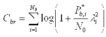
위의 수학식 9에서 λi 는 H br 의 i번째 안테나에 해당하는 고유값(eigen value)을 의미하며, P* b,I는 i번째 안테나의 최적 전력 할당량이며, 다음 수학식 10과 같이 주어진다.In Equation 9 above, λ i denotes an eigen value corresponding to the i th antenna of H br , and P * b, I is an optimal power allocation of the i th antenna, and is given by
[수학식 10]&Quot; (10) "

여기에서 x+ := max(x, 0)이고, μ는 다음 수학식 11과 같이 표현되는 등식을 만족하는 값이다.Here x + : = max (x, 0), μ is a value that satisfies the equation expressed by the following equation (11).
[수학식 11]&Quot; (11) "

한편, 다이버시티 용량 Cdiv 은 위에서 언급한 FDFR 시스템을 기준으로 계산하면 그 결과는 다음 수학식 12와 같다.Meanwhile, if the diversity capacity C div is calculated based on the above-mentioned FDFR system, the result is given by
[수학식 12][Equation 12]

다음으로, 도 13의 시스템을 고려하면, H br 는 기지국-릴레이간 링크(1312)의 4x4 채널 행렬을, H bm 는 기지국-단말기간 링크(1311)의 2x4 MIMO 채널 행렬을, H rm 는 릴레이-단말기간 링크(1313)의 2x4 MIMO 채널 행렬을 각각 나타낸다. 도 13의 시스템은 직접 전송 모드(310), 다이버시티 모드(320), 및 공간 다중화 모드(330)를 모두 지원한다. 따라서, 도 13의 시스템은 단말기에서 측정한 채널 용량에 기초하여 위의 세 가지 전송 모드(310, 320, 330) 중에서 최적의 전송 모드를 선택하여 동작하게 된다.Next, considering the system of FIG. 13, H br is the 4x4 channel matrix of the base station-
도 13의 시스템에 대한 분석은 송신단을 DSTTD(double-space time transmit diversity)로, 수신단을 OSIC-MMSE로 구성하는 경우를 기준으로 신호 모델을 수립함으로써 수행 가능하다.The analysis of the system of FIG. 13 may be performed by establishing a signal model based on a case in which a transmitter is configured with double-space time transmit diversity (DSTTD) and a receiver is configured with OSIC-MMSE.
도 13의 각각의 전송 모드에서의 예상 전송 시간을 도출하기 위한 채널 용량 의 상세한 계산 과정의 기술은 생략할 것이지만, 본 발명은 위의 신호 모델을 기준으로 위와 같이 (Nb, Nr, Nm) = (4, 4, 2) 형태로 구성된 무선 릴레이 시스템에 대해 넓게 미친다.Although the description of the detailed calculation process of the channel capacity for deriving the expected transmission time in each transmission mode of FIG. 13 will be omitted, the present invention is based on the above signal model as described above (N b , N r , N m). ) = Wider for wireless relay systems in the form (4, 4, 2).
이와 같은 사항은 도 11 및 도 12에 도시된 (1, 1, 2) 및 (4, 4, 1) 형태의 시스템에도 적용된다. 즉, 본 발명의 범위는 위와 같은 신호 모델을 통해 위에서 언급한 계산 과정을 통해 도출된 채널 용량을 이용하는 경우 외에, 다른 종류의 신호 모델로부터 다른 방식으로 도출된 채널 용량을 이용하여 예상 전송 시간을 계산함으로써 최적 전송 모드를 선택하는 경우에까지 넓게 미친다고 할 수 있다.The same applies to the systems of the types (1, 1, 2) and (4, 4, 1) shown in FIGS. 11 and 12. That is, the scope of the present invention calculates the estimated transmission time using the channel capacity derived in a different manner from other signal models, in addition to using the channel capacity derived through the above-mentioned calculation process through the signal model as described above. By doing so, it can be said that it extends widely until the optimum transmission mode is selected.
도 14 및 도 15는 각각 도 12 및 도 13과 같이 구성된 무선 릴레이 시스템을 기준으로, 제안된 데이터 전송 제어 방법을 검증하기 위한 모의 실험 결과를 도시한 그래프이다.14 and 15 are graphs showing simulation results for verifying a proposed data transmission control method based on a wireless relay system configured as shown in FIGS. 12 and 13, respectively.
본 모의 실험에 사용된 경로 손실 모델(path loss model)은 수학식 13과 같다.The path loss model used in this simulation is shown in Equation 13.
[수학식 13]&Quot; (13) "

위의 경로 손실 모델과 관련된 파라미터에 대해 간략히 설명하면 다음과 같다. d 는 기지국과 단말기 간의 거리를 의미하고, d0 는 100m로 설정하였다. hb는 기지국의 수직 높이를, s 는 섀도잉(shadowing)을 각각 의미한다. 중심 주파수 fc 가 2 GHz 인 경우를 기준으로 λ 는 0.15m로 설정되었고, a-bhb+c/hb 로 표현되는 γ 값은 기지국-릴레이간 링크에 대해서는 3.28로, 기지국-단말기간 링크에 대해서는 3.76으로, 릴레이-단말기간 링크에 대해서는 4로 각각 결정되었다.The parameters related to the above path loss model are briefly described as follows. d means the distance between the base station and the terminal, d 0 is set to 100m. h b denotes the vertical height of the base station, and s denotes the shadowing. When the center frequency f c is 2 GHz, λ is set to 0.15 m, and the value of γ expressed as a-bh b + c / h b is 3.28 for the base station-relay link and the base station-terminal link. For 3.76 and 4 for relay-terminal links, respectively.
모의 실험에 사용된 그 밖의 파라미터는, Pb는 43dBm, Pr는 40dBm, 주파수 대역은 10MHz, 열 잡음(thermal noise)은 -174dB/Hz, 잡음 지수(noise figure)는 8dB, 기지국과 릴레이 스테이션 사이의 거리는 620m로 고정하고, 기지국과 단말기 사이의 거리는 200m ~ 1600m 사이에서 단계적으로 변화시켰다.Other parameters used in the simulation is, P b is 43dBm, P r is 40dBm, the band is 10MHz, the thermal noise (thermal noise) is -174dB / Hz, NF (noise figure) is 8dB, the base station and the relay stations The distance between them is fixed at 620m, and the distance between the base station and the terminal is changed step by step between 200m ~ 1600m.
도 14는 도 12와 같이 구성된 무선 릴레이 시스템에서, 각각 직접 전송 모드(310), 다이버시티 모드(320), 및 채널 용량에 기초하여 두 가지 전송 모드 중 최적 전송 모드를 선택한 경우의 주파수 효율(spectral efficiency)을 각각 도시한다.FIG. 14 illustrates frequency efficiency when an optimal transmission mode is selected among two transmission modes based on the
도 14를 참조하면, 대략 기지국과 단말기 간의 거리가 400m 이하인 지점에서는 직접 전송 모드(310)로 전송하는 것이 더 나은 성능을 가지며, 그 이상의 거리에서는 릴레이 스테이션과의 협력 전송 방식인 다이버시티 모드(320) 전송의 성능이 더 낫다는 것을 확인할 수 있다.Referring to FIG. 14, when the distance between the base station and the terminal is about 400 m or less, it is better to transmit in the
따라서, 본 발명에 의하면 기지국과 단말기 간의 거리가 대략 400m 이하인 지점에서는 직접 전송 모드(310)로 동작하고, 400m 이상인 지점에서는 다이버시티 모드로 동작하도록 전송 모드 선택을 함으로써 최적의 성능을 얻을 수 있다.Therefore, according to the present invention, the optimal performance can be obtained by selecting the transmission mode to operate in the
구체적으로, 릴레이 스테이션 없이 기지국으로부터 단말기로 데이터를 직접 전송하는 경우에 비해, 기지국으로부터의 거리가 1km인 지점에서의 데이터 전송 스루풋이 5.44bps/Hz에서 8.69bps/Hz로 약 1.6배 증가하였으며, 같은 5.44bps/Hz의 스루풋을 기준으로 할 때 셀 반경이 1km에서 1.5km로 500m 증가하였음을 확인할 수 있다.Specifically, compared to the case of directly transmitting data from a base station to a terminal without a relay station, the data transmission throughput at a point of 1 km from the base station increased by about 1.6 times from 5.44 bps / Hz to 8.69 bps / Hz. Based on the throughput of 5.44bps / Hz, it can be seen that the cell radius increased by 500m from 1km to 1.5km.
도 15는 도 13의 무선 릴레이 시스템에서의 각 전송 모드별 주파수 효율을 도시한다. 앞서 살펴 본 바와 같이, 도 13의 시스템은 직접 전송 모드(310), 다이버시티 모드(320), 및 공간 다중화 모드(330)를 모두 지원한다. 따라서, 도 15의 그래프는 위의 세 가지 전송 모드(310, 320, 330)로 고정된 경우의 성능과, 기지국으로부터 단말기까지의 거리에 따라 위의 세 가지 전송 모드(310, 320, 330) 중 최적의 전송 모드를 선택하여 전송하는 경우의 성능을 함께 도시한다.FIG. 15 illustrates frequency efficiency of each transmission mode in the wireless relay system of FIG. 13. As described above, the system of FIG. 13 supports both the
도 15의 그래프를 참조하면, 기지국과 단말기 사이의 거리가 대략 500m 이하인 지점에서는 직접 전송 모드(310)를 통한 전송이 우수한 성능을 보이는 반면에, 500m 이상인 지점에서는 릴레이 스테이션을 이용하는 다이버시티 모드(320)와 공간 다중화 모드(330)의 성능이 월등히 우수함을 확인할 수 있다.Referring to the graph of FIG. 15, while the distance between the base station and the terminal is approximately 500 m or less, the transmission through the
또한, 대부분의 경우에 다이버시티 모드(320)보다 공간 다중화 모드(330)에서의 성능이 더 우수함을 확인할 수 있는데, 이는 본 발명을 통해 제안되는 새로운 데이터 전송 방식인 공간 다중화 모드(330)의 성능 향상 효과를 입증해 준다.In addition, in most cases, it can be seen that the performance in the
구체적으로, 종래의 직접 전송 방식에 비해 기지국으로부터의 거리가 1km인 지점에서의 데이터 전송 스루풋이 9.88bps/Hz에서 12.6bps/Hz로 약 1.3배 증가하였으며, 같은 9.88bps/Hz의 스루풋을 기준으로 했을 때, 셀 반경이 1km에서 1.25km로 250m 증가하였음을 확인할 수 있다.Specifically, compared to the conventional direct transmission method, the data transmission throughput at the point where the distance from the base station is 1km is increased by about 1.3 times from 9.88bps / Hz to 12.6bps / Hz, based on the same throughput of 9.88bps / Hz. When the cell radius is increased by 250m from 1km to 1.25km.
지금까지 도 11 내지 도 15를 참조하여 본 발명에 따른 무선 릴레이 시스템에 대해 설명하였다. 상술한 무선 릴레이 시스템에는 앞서 도 3 내지 도 10과 관련하여 설명한 실시예들의 세부 내용이 그대로 적용될 수 있으므로, 상기 시스템과 관련한 더 이상의 상세한 설명을 생략하도록 한다.So far, the wireless relay system according to the present invention has been described with reference to FIGS. 11 to 15. Since the details of the embodiments described above with reference to FIGS. 3 to 10 may be applied to the above-described wireless relay system, further detailed description of the system will be omitted.
이상과 같이 본 발명에서는 구체적인 구성 요소 등과 같은 특정 사항들과 한정된 실시예 및 도면에 의해 설명되었으나 이는 본 발명의 보다 전반적인 이해를 돕기 위해서 제공된 것일 뿐, 본 발명은 상기의 실시예에 한정되는 것은 아니며, 본 발명이 속하는 분야에서 통상의 지식을 가진 자라면 이러한 기재로부터 다양한 수정 및 변형이 가능하다.As described above, the present invention has been described with reference to particular embodiments, such as specific elements, and specific embodiments and drawings. However, it should be understood that the present invention is not limited to the above- And various modifications and changes may be made thereto by those skilled in the art to which the present invention pertains.
따라서, 본 발명의 사상은 설명된 실시예에 국한되어 정해져서는 아니되며, 후술하는 특허청구범위뿐 아니라 이 특허청구범위와 균등하거나 등가적 변형이 있는 모든 것들은 본 발명 사상의 범주에 속한다고 할 것이다.Accordingly, the spirit of the present invention should not be construed as being limited to the embodiments described, and all of the equivalents or equivalents of the claims, as well as the following claims, belong to the scope of the present invention .
본 발명에 따른 데이터 전송 및 데이터 전송 제어 방법, 그리고 위의 방법이 적용된 무선 릴레이 시스템에 의하면, 셀 내의 단말기와 릴레이 스테이션의 위치에 따라 데이터 전송 모드를 적응적으로 변화시킴으로써 주파수 효율을 향상시킬 수 있다.According to the data transmission and data transmission control method according to the present invention, and the wireless relay system to which the above method is applied, frequency efficiency can be improved by adaptively changing the data transmission mode according to the position of the terminal and the relay station in the cell. .
구체적으로, 본 발명에 의하면 단말기에서 측정한 무선 링크별 채널 용량에 기초하여 직접 전송 모드, 다이버시티 전송 모드, 및 공간 다중화 모드 중에서 어 느 하나를 선택하여 선택된 전송 모드에 따라 기지국과 릴레이 스테이션이 동작하도록 함으로써, 어느 하나의 고정된 전송 방식을 이용하는 경우에 비해 데이터 전송 스루풋을 증가시킬 수 있다.Specifically, according to the present invention, the base station and the relay station operate according to the selected transmission mode by selecting one of the direct transmission mode, the diversity transmission mode, and the spatial multiplexing mode based on the channel capacity of each radio link measured by the terminal. By doing so, data transmission throughput can be increased as compared with the case of using any one of the fixed transmission schemes.
또한, 본 발명이 제안하는 공간 다중화 방식의 데이터 전송 방법에 의하면 기지국에서 단말기로의 직접 전송 경로와 릴레이 스테이션을 경유하는 우회 경로를 통해 각각 전체 데이터의 서로 다른 일정 비율을 전송함으로써 다중화 이득을 얻을 수 있다.In addition, according to the data transmission method of the spatial multiplexing method proposed by the present invention, a multiplexing gain can be obtained by transmitting different constant ratios of all data through a direct transmission path from a base station to a terminal and a bypass path via a relay station. have.
또한, 본 발명에 의하면 단말기에서 측정한 무선 링크별 채널 용량에 기초하여 기지국과 릴레이 스테이션의 MCS 레벨을 결정함으로써, 보다 정교한 데이터 전송 제어가 가능하게 된다.In addition, according to the present invention, by determining the MCS level of the base station and the relay station based on the channel capacity for each radio link measured by the terminal, more precise data transmission control is possible.
또한, 본 발명에 의하면 셀 반경이 고정되어 있는 경우에 기지국에서 단말기로의 다운링크 데이터 전송의 스루풋을 증가시킴으로써 이동통신 시스템의 셀 용량을 증대할 수 있다. 즉, 개별 셀 내에서 지원 가능한 사용자의 수를 증가시킬 수 있게 된다. 또 달리, 이는 곧 개별 사용자에게 지원 가능한 데이터 전송률을 증가시킬 수 있음을 의미하기도 한다.In addition, according to the present invention, when the cell radius is fixed, the cell capacity of the mobile communication system can be increased by increasing the throughput of downlink data transmission from the base station to the terminal. That is, it is possible to increase the number of users that can be supported in individual cells. Alternatively, this also means increasing the data rate available to individual users.
또한, 본 발명에 의하면 동일한 셀 용량을 지원하는 셀 반경을 확장함으로써, 이동통신 시스템의 초기 설치 비용을 절감하고, 효율적인 셀 계획을 가능하게 한다. 이에 따라, 고품질의 이동통신 서비스를 사용자에게 저렴한 가격으로 제공할 수 있게 되어 이동통신 서비스의 보급을 촉진하고, 나아가 더욱 다양한 종류의 서비스를 창출하기 위한 기반 환경을 제공할 수 있다.In addition, according to the present invention, by extending the cell radius to support the same cell capacity, it is possible to reduce the initial installation cost of the mobile communication system, and enable efficient cell planning. Accordingly, it is possible to provide a high quality mobile communication service to the user at a low price to promote the spread of the mobile communication service, and further provide a base environment for creating more various kinds of services.
Claims (33)


Priority Applications (4)
| Application Number | Priority Date | Filing Date | Title |
|---|---|---|---|
| KR1020060078940A KR101213155B1 (en) | 2006-08-21 | 2006-08-21 | Method of controlling data transmission in a wireless relay system, and the relay system implementing the method |
| US11/638,575 US8150409B2 (en) | 2006-08-21 | 2006-12-14 | Method of controlling data transmission in a wireless relay system, and the relay system implementing the method |
| PCT/KR2007/002264 WO2008023878A1 (en) | 2006-08-21 | 2007-05-09 | Method of controlling data transmission in a wireless relay system, and the relay system implementing the method |
| EP07746417.0A EP2060026B1 (en) | 2006-08-21 | 2007-05-09 | Method of controlling data transmission in a wireless relay system, and the relay system implementing the method |
Applications Claiming Priority (1)
| Application Number | Priority Date | Filing Date | Title |
|---|---|---|---|
| KR1020060078940A KR101213155B1 (en) | 2006-08-21 | 2006-08-21 | Method of controlling data transmission in a wireless relay system, and the relay system implementing the method |
Publications (2)
| Publication Number | Publication Date |
|---|---|
| KR20080017629A KR20080017629A (en) | 2008-02-27 |
| KR101213155B1 true KR101213155B1 (en) | 2012-12-17 |
Family
ID=39101955
Family Applications (1)
| Application Number | Title | Priority Date | Filing Date |
|---|---|---|---|
| KR1020060078940A KR101213155B1 (en) | 2006-08-21 | 2006-08-21 | Method of controlling data transmission in a wireless relay system, and the relay system implementing the method |
Country Status (4)
| Country | Link |
|---|---|
| US (1) | US8150409B2 (en) |
| EP (1) | EP2060026B1 (en) |
| KR (1) | KR101213155B1 (en) |
| WO (1) | WO2008023878A1 (en) |
Families Citing this family (40)
| Publication number | Priority date | Publication date | Assignee | Title |
|---|---|---|---|---|
| KR101213155B1 (en) * | 2006-08-21 | 2012-12-17 | 삼성전자주식회사 | Method of controlling data transmission in a wireless relay system, and the relay system implementing the method |
| KR100957409B1 (en) | 2006-11-30 | 2010-05-11 | 삼성전자주식회사 | System and method for controlling power in a communication system |
| KR100829221B1 (en) * | 2007-01-26 | 2008-05-14 | 삼성전자주식회사 | Method of controlling data transmission mode in an orthogonal frequency division multeplexing wireless relay system, and aparatus using the same |
| KR100904295B1 (en) * | 2007-08-07 | 2009-06-25 | 한국전자통신연구원 | Method for connection and relaying of a base station and repeaters for spatial division multiple access |
| US20090122744A1 (en) * | 2007-11-09 | 2009-05-14 | Alexander Maltsev | Selective relaying for wireless networks |
| US8542760B2 (en) * | 2007-11-16 | 2013-09-24 | Lingna Holdings Pte., Llc | Full-rate distributed space-time codes for cooperative communications |
| CN101965741B (en) * | 2008-01-02 | 2014-12-31 | 交互数字技术公司 | Method and apparatus for cooperative wireless communications |
| CN102138352A (en) * | 2008-02-25 | 2011-07-27 | 爱立信电话股份有限公司 | Relays in multi-user MIMO systems |
| KR101449024B1 (en) * | 2008-03-14 | 2014-10-10 | 엘지전자 주식회사 | Method for transmitting data in DLS Wireless Network and apparatus supporting the method, and frame format for the data transmission method |
| CN102187594B (en) * | 2008-08-20 | 2014-10-29 | Lg伊诺特有限公司 | Mimo communication system and control method thereof |
| KR100962994B1 (en) * | 2008-09-01 | 2010-06-09 | 성균관대학교산학협력단 | A method for dynamically modulating and coding the broadcasting data which is transmitted over mbs relay system using mcs |
| WO2010027136A1 (en) * | 2008-09-03 | 2010-03-11 | Lg Electronics Inc. | Realy station and method of operating the same |
| US8059622B2 (en) * | 2008-09-04 | 2011-11-15 | Intel Corporation | Multi-radio platform and method for coordinating activities between a broadband wireless access network transceiver and co-located transceiver |
| US8953467B2 (en) | 2008-09-08 | 2015-02-10 | Nokia Corporation | Adaptive transmission modes for transparent relay |
| JP5187132B2 (en) * | 2008-10-21 | 2013-04-24 | 富士通株式会社 | COMMUNICATION DEVICE, COMMUNICATION SYSTEM, AND COMMUNICATION METHOD |
| KR101466083B1 (en) * | 2008-10-30 | 2014-12-15 | 삼성전자주식회사 | Method and system for cooperative relaying at multi hop relay network |
| US8902807B2 (en) | 2009-02-13 | 2014-12-02 | Electronics And Telecommunications Research Institute | Relay system based on resource allocation |
| CN101835238A (en) * | 2009-03-11 | 2010-09-15 | 中兴通讯股份有限公司 | Method and device for selecting route in junction network |
| KR101502602B1 (en) | 2009-03-17 | 2015-03-25 | 삼성전자주식회사 | Terminal device and method for selecting relay node of the terminal |
| US9432991B2 (en) * | 2009-04-21 | 2016-08-30 | Qualcomm Incorporated | Enabling support for transparent relays in wireless communication |
| KR101642311B1 (en) | 2009-07-24 | 2016-07-25 | 엘지전자 주식회사 | The method for transmitting and receiving CoMP reference signal |
| EP2293466B1 (en) * | 2009-09-03 | 2013-08-28 | Mitsubishi Electric R&D Centre Europe B.V. | Method and a device for relaying symbols transferred by a source to a destination |
| KR101764888B1 (en) * | 2010-02-16 | 2017-08-16 | 한국전자통신연구원 | Apparatus and method for wideband high frequency short-range wireless communication |
| TWI430689B (en) * | 2010-08-03 | 2014-03-11 | Inst Information Industry | Power distribution apparatus, power distribution method, and computer program product thereof |
| US8942116B2 (en) * | 2010-09-27 | 2015-01-27 | Ceragon Networks Ltd. | Asymmetrical link configuration for increased total network capacity |
| JP5644343B2 (en) * | 2010-10-05 | 2014-12-24 | 富士通株式会社 | Data transmission method, transmission source information processing apparatus, data transmission system, and data transmission program |
| KR101719509B1 (en) * | 2010-10-06 | 2017-03-24 | 삼성전자주식회사 | Communication method of vehicular access point, vehicular user equipment and macro base station for user in the vehicle |
| EP2487807B1 (en) * | 2011-02-10 | 2016-05-11 | Mitsubishi Electric R&D Centre Europe B.V. | Method for increasing quality of signals received by a destination device |
| TW201251394A (en) * | 2011-06-10 | 2012-12-16 | Nat Univ Chung Cheng | Overlay network encoding method |
| US8780862B2 (en) * | 2011-10-14 | 2014-07-15 | The Mitre Corporation | VDL2 power control |
| CN104303485B (en) * | 2012-04-13 | 2017-08-25 | 三星电子株式会社 | Method and device for transmitting packet in cloud cell |
| CN102740303B (en) * | 2012-05-28 | 2015-01-21 | 上海交通大学 | Combined power distribution and sub-carrier matching method of improved type relay system |
| WO2014005307A1 (en) * | 2012-07-04 | 2014-01-09 | 华为技术有限公司 | Method and device for communications |
| US9867163B2 (en) | 2012-07-12 | 2018-01-09 | Qualcomm Incorporated | Methods and apparatus for power saving in broadcasting carrier information |
| US9686818B2 (en) * | 2014-09-02 | 2017-06-20 | Texas Instruments Incorporated | Systems and methods of power efficient Wi-Fi |
| WO2017163069A1 (en) * | 2016-03-22 | 2017-09-28 | Novus4 Limited | A method and system for controlling data transmission |
| US10461898B2 (en) * | 2017-06-08 | 2019-10-29 | Bank Of America Corporation | Parallel data transmission |
| EP3503427B1 (en) * | 2017-12-22 | 2020-07-22 | Deutsche Telekom AG | Base station system for transmitting a data stream towards a user entity |
| KR102024756B1 (en) * | 2018-09-28 | 2019-09-25 | 넥서스텍(주) | multi-hop routing apparatus and method for WiFi cooperative relay communication |
| US10805874B1 (en) | 2019-02-25 | 2020-10-13 | Sprint Communications Company L.P. | Frequency channel lock in wireless data relays |
Citations (2)
| Publication number | Priority date | Publication date | Assignee | Title |
|---|---|---|---|---|
| EP1613006A1 (en) | 2004-06-30 | 2006-01-04 | Alcatel | Ad-hoc extensions of a cellular air interface |
| JP2006148570A (en) * | 2004-11-19 | 2006-06-08 | Sharp Corp | Communication repeater, terminal side communication apparatus, communication apparatus, communication system, method for controlling communication, communication program, and computer readable recording medium for recoreing communication control program therein |
Family Cites Families (16)
| Publication number | Priority date | Publication date | Assignee | Title |
|---|---|---|---|---|
| WO1990004315A1 (en) * | 1988-10-15 | 1990-04-19 | Schlumberger Industries | Assembly for the remote transfer and collection of data, particularly from meters |
| NL1017870C2 (en) * | 2001-04-18 | 2002-10-25 | Marc Van Oldenborgh | Method for inverse multiplexing. |
| TWI289999B (en) * | 2001-06-08 | 2007-11-11 | Benq Corp | Transmission method for relay signal of wireless communication system |
| JP2003009236A (en) | 2001-06-20 | 2003-01-10 | Yamatake Corp | Radio equipment |
| US6601009B2 (en) * | 2001-07-12 | 2003-07-29 | Yahoo Inc | Method and system of automatic bandwidth detection |
| JP2003318810A (en) | 2002-04-26 | 2003-11-07 | Kobe Steel Ltd | Radio data collection system and radio data repeater |
| DE602004012250T2 (en) * | 2003-05-28 | 2009-03-19 | Telefonaktiebolaget Lm Ericsson (Publ) | METHOD AND SYSTEM FOR WIRELESS COMMUNICATION NETWORKS WITH FORWARDING |
| JP2004363645A (en) | 2003-05-30 | 2004-12-24 | Toshiba Corp | Transmission apparatus and method, as well as program |
| AU2003298477B2 (en) | 2003-12-30 | 2008-10-02 | Nokia Technologies Oy | Communication system using relay base stations with asymmetric data links |
| JP4394474B2 (en) | 2004-02-16 | 2010-01-06 | 株式会社エヌ・ティ・ティ・ドコモ | Wireless relay system, wireless relay device, and wireless relay method |
| JP4425863B2 (en) * | 2004-02-18 | 2010-03-03 | 株式会社エヌ・ティ・ティ・ドコモ | Packet transfer system and radio base station |
| KR20060035358A (en) | 2004-10-22 | 2006-04-26 | 삼성전자주식회사 | Apparatus and method for communicating high-speed data in communication system using multiple txs and rxs |
| KR100594051B1 (en) | 2004-11-26 | 2006-06-30 | 삼성전자주식회사 | Apparatus and method for efficient interference cancellation in cooperate relay networks in the mimo cellular system |
| US20070076649A1 (en) * | 2005-09-30 | 2007-04-05 | Intel Corporation | Techniques for heterogeneous radio cooperation |
| US20070177545A1 (en) * | 2006-01-30 | 2007-08-02 | Natarajan Kadathur S | System and method for allocating sub-channels in a network |
| KR101213155B1 (en) * | 2006-08-21 | 2012-12-17 | 삼성전자주식회사 | Method of controlling data transmission in a wireless relay system, and the relay system implementing the method |
-
2006
- 2006-08-21 KR KR1020060078940A patent/KR101213155B1/en active IP Right Grant
- 2006-12-14 US US11/638,575 patent/US8150409B2/en active Active
-
2007
- 2007-05-09 EP EP07746417.0A patent/EP2060026B1/en active Active
- 2007-05-09 WO PCT/KR2007/002264 patent/WO2008023878A1/en active Application Filing
Patent Citations (2)
| Publication number | Priority date | Publication date | Assignee | Title |
|---|---|---|---|---|
| EP1613006A1 (en) | 2004-06-30 | 2006-01-04 | Alcatel | Ad-hoc extensions of a cellular air interface |
| JP2006148570A (en) * | 2004-11-19 | 2006-06-08 | Sharp Corp | Communication repeater, terminal side communication apparatus, communication apparatus, communication system, method for controlling communication, communication program, and computer readable recording medium for recoreing communication control program therein |
Also Published As
| Publication number | Publication date |
|---|---|
| WO2008023878A1 (en) | 2008-02-28 |
| US8150409B2 (en) | 2012-04-03 |
| KR20080017629A (en) | 2008-02-27 |
| US20080045212A1 (en) | 2008-02-21 |
| EP2060026A1 (en) | 2009-05-20 |
| EP2060026A4 (en) | 2015-04-15 |
| EP2060026B1 (en) | 2019-04-03 |
Similar Documents
| Publication | Publication Date | Title |
|---|---|---|
| KR101213155B1 (en) | Method of controlling data transmission in a wireless relay system, and the relay system implementing the method | |
| US8750788B2 (en) | Multiple data stream transmission method and apparatus in relay system | |
| KR100829221B1 (en) | Method of controlling data transmission mode in an orthogonal frequency division multeplexing wireless relay system, and aparatus using the same | |
| CN101479961B (en) | Multi-antenna relay with self-interference cancellation | |
| CN101729110B (en) | Method and system for wireless communication networks using cooperative relaying | |
| CN101322327B (en) | Method, device and system for relay information in wireless relay network | |
| KR100969147B1 (en) | Method and system for operating cooperative receive diversity, selective cooperative relaying | |
| CN101217301B (en) | A collaborative transmission method realized in isomerization wireless network with cooperating relay nodes | |
| KR100975705B1 (en) | System and method for transmitting/receiving signal in a mobile communication system | |
| KR101497929B1 (en) | Multiple-relay based multiple input multiple output communication system | |
| KR20100034675A (en) | Method for controlling uplink power for multi-cell cooperative radio communication system and terminal supporting the method | |
| Muñoz et al. | Non-regenerative MIMO relaying with channel state information [cellular example] | |
| JP2008530946A (en) | Method and apparatus for cooperative relay | |
| JP2009284478A (en) | Method for allocating power to source station and relay stations in two-hop amplify-and-forward relay multi-input-multi-output networks | |
| Jing et al. | Single and multiple relay selection schemes and their diversity orders | |
| KR101329153B1 (en) | Wireless communication apparatus and wireless communication method using the apparatus | |
| CN105979556B (en) | Take into account the fair relay selection method of rate and energy efficiency | |
| Sunil | Performance analysis of moving multi-antenna relay cooperation with hybrid relaying scheme in cooperative wireless networks | |
| KR101072453B1 (en) | Cooperative multi hop relay apparatus and method thereof | |
| KR101071803B1 (en) | Decode-and-Forward relay system and Method for controlling the same | |
| Ahmed et al. | To cooperate or not to cooperate? That is the question! | |
| Mangayarkarasi et al. | An efficient IR-HARQ power allocation for relay-aided cellular networks | |
| Darmawan et al. | Downlink Cooperative Wireless Spatial Multiplexing System | |
| Yilmaz et al. | Some systems aspects regarding compressive relaying with wireless infrastructure links | |
| KR101376038B1 (en) | Method and apparatus for transmitting data in a communication system |
Legal Events
| Date | Code | Title | Description |
|---|---|---|---|
| A201 | Request for examination | ||
| E701 | Decision to grant or registration of patent right | ||
| GRNT | Written decision to grant | ||
| FPAY | Annual fee payment |
Payment date: 20151118 Year of fee payment: 4 |
|
| FPAY | Annual fee payment |
Payment date: 20161121 Year of fee payment: 5 |
|
| FPAY | Annual fee payment |
Payment date: 20171121 Year of fee payment: 6 |
|
| FPAY | Annual fee payment |
Payment date: 20181119 Year of fee payment: 7 |