KR101169895B1 - Picture Coding Method, Picture Decoding Method, Picture Coding Apparatus, Picture Decoding Apparatus, and Program thereof - Google Patents
Picture Coding Method, Picture Decoding Method, Picture Coding Apparatus, Picture Decoding Apparatus, and Program thereof Download PDFInfo
- Publication number
- KR101169895B1 KR101169895B1 KR1020117014691A KR20117014691A KR101169895B1 KR 101169895 B1 KR101169895 B1 KR 101169895B1 KR 1020117014691 A KR1020117014691 A KR 1020117014691A KR 20117014691 A KR20117014691 A KR 20117014691A KR 101169895 B1 KR101169895 B1 KR 101169895B1
- Authority
- KR
- South Korea
- Prior art keywords
- value
- difference
- picture
- encoding
- difference value
- Prior art date
Links
Images


Classifications
-
- H—ELECTRICITY
- H04—ELECTRIC COMMUNICATION TECHNIQUE
- H04N—PICTORIAL COMMUNICATION, e.g. TELEVISION
- H04N19/00—Methods or arrangements for coding, decoding, compressing or decompressing digital video signals
- H04N19/10—Methods or arrangements for coding, decoding, compressing or decompressing digital video signals using adaptive coding
- H04N19/134—Methods or arrangements for coding, decoding, compressing or decompressing digital video signals using adaptive coding characterised by the element, parameter or criterion affecting or controlling the adaptive coding
- H04N19/136—Incoming video signal characteristics or properties
-
- H—ELECTRICITY
- H04—ELECTRIC COMMUNICATION TECHNIQUE
- H04N—PICTORIAL COMMUNICATION, e.g. TELEVISION
- H04N19/00—Methods or arrangements for coding, decoding, compressing or decompressing digital video signals
- H04N19/60—Methods or arrangements for coding, decoding, compressing or decompressing digital video signals using transform coding
-
- H—ELECTRICITY
- H04—ELECTRIC COMMUNICATION TECHNIQUE
- H04N—PICTORIAL COMMUNICATION, e.g. TELEVISION
- H04N19/00—Methods or arrangements for coding, decoding, compressing or decompressing digital video signals
- H04N19/10—Methods or arrangements for coding, decoding, compressing or decompressing digital video signals using adaptive coding
- H04N19/102—Methods or arrangements for coding, decoding, compressing or decompressing digital video signals using adaptive coding characterised by the element, parameter or selection affected or controlled by the adaptive coding
- H04N19/124—Quantisation
- H04N19/126—Details of normalisation or weighting functions, e.g. normalisation matrices or variable uniform quantisers
-
- H—ELECTRICITY
- H04—ELECTRIC COMMUNICATION TECHNIQUE
- H04N—PICTORIAL COMMUNICATION, e.g. TELEVISION
- H04N19/00—Methods or arrangements for coding, decoding, compressing or decompressing digital video signals
- H04N19/10—Methods or arrangements for coding, decoding, compressing or decompressing digital video signals using adaptive coding
- H04N19/169—Methods or arrangements for coding, decoding, compressing or decompressing digital video signals using adaptive coding characterised by the coding unit, i.e. the structural portion or semantic portion of the video signal being the object or the subject of the adaptive coding
- H04N19/17—Methods or arrangements for coding, decoding, compressing or decompressing digital video signals using adaptive coding characterised by the coding unit, i.e. the structural portion or semantic portion of the video signal being the object or the subject of the adaptive coding the unit being an image region, e.g. an object
- H04N19/176—Methods or arrangements for coding, decoding, compressing or decompressing digital video signals using adaptive coding characterised by the coding unit, i.e. the structural portion or semantic portion of the video signal being the object or the subject of the adaptive coding the unit being an image region, e.g. an object the region being a block, e.g. a macroblock
-
- H—ELECTRICITY
- H04—ELECTRIC COMMUNICATION TECHNIQUE
- H04N—PICTORIAL COMMUNICATION, e.g. TELEVISION
- H04N19/00—Methods or arrangements for coding, decoding, compressing or decompressing digital video signals
- H04N19/10—Methods or arrangements for coding, decoding, compressing or decompressing digital video signals using adaptive coding
- H04N19/189—Methods or arrangements for coding, decoding, compressing or decompressing digital video signals using adaptive coding characterised by the adaptation method, adaptation tool or adaptation type used for the adaptive coding
- H04N19/196—Methods or arrangements for coding, decoding, compressing or decompressing digital video signals using adaptive coding characterised by the adaptation method, adaptation tool or adaptation type used for the adaptive coding being specially adapted for the computation of encoding parameters, e.g. by averaging previously computed encoding parameters
-
- H—ELECTRICITY
- H04—ELECTRIC COMMUNICATION TECHNIQUE
- H04N—PICTORIAL COMMUNICATION, e.g. TELEVISION
- H04N19/00—Methods or arrangements for coding, decoding, compressing or decompressing digital video signals
- H04N19/46—Embedding additional information in the video signal during the compression process
- H04N19/463—Embedding additional information in the video signal during the compression process by compressing encoding parameters before transmission
-
- H—ELECTRICITY
- H04—ELECTRIC COMMUNICATION TECHNIQUE
- H04N—PICTORIAL COMMUNICATION, e.g. TELEVISION
- H04N19/00—Methods or arrangements for coding, decoding, compressing or decompressing digital video signals
- H04N19/60—Methods or arrangements for coding, decoding, compressing or decompressing digital video signals using transform coding
- H04N19/61—Methods or arrangements for coding, decoding, compressing or decompressing digital video signals using transform coding in combination with predictive coding
-
- H—ELECTRICITY
- H04—ELECTRIC COMMUNICATION TECHNIQUE
- H04N—PICTORIAL COMMUNICATION, e.g. TELEVISION
- H04N19/00—Methods or arrangements for coding, decoding, compressing or decompressing digital video signals
- H04N19/90—Methods or arrangements for coding, decoding, compressing or decompressing digital video signals using coding techniques not provided for in groups H04N19/10-H04N19/85, e.g. fractals
- H04N19/91—Entropy coding, e.g. variable length coding [VLC] or arithmetic coding
Abstract
본 발명에 따른 화상 부호화 방법은 직교변환 및 양자화를 통하여 블록 단위로 화상을 부호화하고, 직교 변환 계수의 주파수에 대한 양자화 단계를 도출하기 위해 사용되는 양자화 매트릭스를 부호화하는 화상 부호화 방법이고, 양자화 매트릭스에 포함된 각 주파수 성분과 상기 각각의 주파수 성분에 대응하는 소정 값 사이의 차이 값을 계산하는 단계; 및 상기 차이 값을 가변 길이 부호로 부호화하는 단계를 포함하고, 상기 차이 값이 상기 차이 값의 인접하는 차이 값의 부호 길이보다 작거나 또는 같을 수록, 가변 길이 부호의 부호 길이는 더 짧다.An image encoding method according to the present invention is an image encoding method for encoding an image in units of blocks through orthogonal transformation and quantization, and encoding a quantization matrix used for deriving a quantization step for a frequency of an orthogonal transformation coefficient. Calculating a difference value between each frequency component included and a predetermined value corresponding to each frequency component; And encoding the difference value with a variable length code, wherein the difference length is less than or equal to the code length of the adjacent difference value of the difference value, the shorter the code length of the variable length code.

Description
본 출원은 그 내용이 여기에 참고로 포함되어 있는, 2004년 1월 20일 출원된 미국 임시 출원 번호 60/538,065의 이익, 및 2004년 4월 12일 출원된 미국 임시 출원 번호 60/561,351의 이익을 청구한다.This application claims the benefit of US Provisional Application No. 60 / 538,065, filed Jan. 20, 2004, and the provisional application of US Provisional Application No. 60 / 561,351, filed April 12, 2004, the content of which is incorporated herein by reference. Charges.
본 발명은 동화상을 효율적으로 압축하는 화상 부호화 방법, 및 이렇게 압축된 동화상을 정확하게 복호화하는 화상 복호화 방법뿐만 아니라, 화상 부호화 장치, 화상 복호화 장치 및 그 프로그램에 관한 것이다.The present invention relates not only to a picture coding method for efficiently compressing a moving picture, and to a picture coding method for accurately decoding such compressed video, but also to a picture coding apparatus, a picture decoding apparatus and a program thereof.
오디오, 비디오 및 다른 화소 값들을 통합적으로 다루는 멀티미디어의 시대에서, 현존하는 정보 매체, 즉, 사람들에게 정보를 전달하는 신문, 잡지, 텔레비젼, 라디오, 전화기 및 다른 수단은 최근 멀티미디어의 범위에 포함되어 오고 있다. 일반적으로, 멀티미디어란 문자뿐만 아니라 그래픽, 오디오, 특히 화상 등을 함께 결합시켜서 표현되는 것을 말한다. 그러나, 상기 서술한 현존의 정보 미디어를 멀티미디어의 범위에 포함시키기 위해, 이러한 정보를 디지털 형태로 표현하는 것이 반드시 필요하다.In the age of multimedia integrating audio, video and other pixel values, existing information media, newspapers, magazines, television, radio, telephones and other means of communicating information to people, have recently been included in the scope of multimedia. have. In general, multimedia refers to a combination of not only characters but also graphics, audio, and in particular images. However, in order to include the existing information media described above in the scope of multimedia, it is necessary to express such information in digital form.
그러나, 각각의 상기 서술된 정보 미디어에 포함된 정보의 양을 디지털 정보의 양으로서 계산할 때, 문자당 정보의 양은 1~2바이트이고, 오디오의 경우 요구되는 정보의 양은 초당 64Kbits(전화 품질)이고, 동화상의 경우 초당 100Mbits(현재 텔레비젼 수신 품질)이다. 그러므로, 앞에 서술된 정보 미디어가 이러한 거대한 양의 정보를 디지털 형태로 취급하기 위한 것은 현실적이지 않다. 예를 들면, 비디오 폰은 64Kbits/s ~ 1.5Mbits/s의 전송 속도를 제공하는 ISDN(Integrated Services Digital Network)을 이용하여 이미 실제 사용중이지만, ISDN을 통해 전화 및 카메라의 비디오를 직접 전송하는 것은 실용적이지 않다.However, when calculating the amount of information contained in each of the above described information media as the amount of digital information, the amount of information per character is 1 to 2 bytes, and for audio, the amount of information required is 64 Kbits per second (telephone quality). For video, 100 Mbits per second (current television reception quality). Therefore, it is not practical for the information media described above to handle this huge amount of information in digital form. For example, video phones are already in use using an Integrated Services Digital Network (ISDN), which offers transfer rates from 64 Kbits / s to 1.5 Mbits / s, but it is practical to transfer video from telephones and cameras directly over ISDN. It is not
이것을 배경으로 하여, 정보 압축 기술이 요구되고 있고, ITU-T(International Telecommunication Union-Telecommunication Standardization Sector)에 의해 추천되는 H.261 및 H.263 표준을 따르는 동화상 압축 기술은 예를 들면 비디오 폰에 대해서 이용되고 있다. 더욱이, MPEC-1 표준에 따르는 정보 압축 기술에 의하면, 화상 정보를 통상의 음악 CD(Compact Disk)에 사운드 정보와 함께 저장하는 것이 가능하다.Against this background, information compression techniques are required, and moving picture compression techniques complying with the H.261 and H.263 standards recommended by the International Telecommunication Union-Telecommunication Standardization Sector (ITU-T) are, for example, for video phones. It is used. Furthermore, according to the information compression technique conforming to the MPEC-1 standard, it is possible to store image information together with sound information on a normal music CD (Compact Disk).
여기서, MPEG(Moving Picture Experts Group)은 ISO/IEC(International Organization for Standardization, Internatioanl Electrotechnical Commission)에 의해 규격화된 동화상 신호의 압축의 국제적인 표준이고, MPEG-1은 텔레비젼 신호 정보를 대략 100분의 일로 압축하는 표준이므로, 동화상 신호는 1.5Mbit/s의 비율로 전송된다. 더욱이, MPEG-1 표준에 의해 달성된 전송 속도가 대략 1.5Mbit/s의 중간 품질 속도이고, 더욱 개선된 화상 품질에 대한 요구를 만족하기 위한 표준인 MPEG-2는, 동화상 신호가 2 ~ 15Mbit/s의 비율로 전송되는 텔레비젼 방송의 품질과 같은 데이터가 전송되도록 한다. 또한, MPEG-4는 MPEG-1, MPEG-2의 표준을 발전시킨 작업 그룹(ISO/IEC JTC1/SC29/WG11)에 의해 표준화되었다. MPEG-4는 MPEG-1, MPEG-2보다 더 높은 압축율을 제공하고, 물체 단위로 부호화/복호화/조작을 가능하게 하고, 멀티미디어 시대에 요구되는 새로운 기능을 제공할 수 있다. 표준화 단계의 초기에, MPEG-4는 저비트 레이트의 부호화 방법을 지향했지만, 고비트 레이트 부호화 뿐만 아니라 인터레이스 이미지를 다루는 보다 일반적인 부호화를 지원하는 표준으로서 확장되어 오고 있다. 현재, 더 높은 압축률을 제공하는 차세대의 화상 부호화 방법으로서 MPEG-4 AVC 및 ITU-T H.264를 표준화하기 위한 노력이 ISO/IEC 및 ITU-T에 의해 연합으로 행해져 오고 있다. 2002년 8월 시점에서, 차세대의 화상 부호화 방법에 대해서 CD(committee draft)가 발행되었다.Here, the Moving Picture Experts Group (MPEG) is an international standard for the compression of moving picture signals standardized by ISO / IEC (International Organization for Standardization, International Electrotechnical Commission), and MPEG-1 compresses television signal information into approximately one hundredth of a second. As a standard, the moving picture signal is transmitted at a rate of 1.5 Mbit / s. Moreover, the transmission speed achieved by the MPEG-1 standard is a medium quality speed of approximately 1.5 Mbit / s, and MPEG-2, which is a standard for satisfying the demand for further improved picture quality, has a moving picture signal of 2 to 15 Mbit / s. Allows data to be transmitted, such as the quality of television broadcast transmitted at the rate of s. In addition, MPEG-4 has been standardized by the working group (ISO / IEC JTC1 / SC29 / WG11), which developed the standards of MPEG-1 and MPEG-2. MPEG-4 can provide a higher compression rate than MPEG-1 and MPEG-2, enable encoding / decoding / manipulation on a per-object basis, and provide new functions required in the multimedia era. In the early days of the standardization phase, MPEG-4 was aimed at a low bit rate encoding method, but it has been extended as a standard to support not only high bit rate encoding but also more general encoding that deals with interlaced images. At present, efforts to standardize MPEG-4 AVC and ITU-T H.264 as a next-generation picture coding method providing higher compression rates have been made in association by ISO / IEC and ITU-T. As of August 2002, a CD (committee draft) was issued for the next-generation picture coding method.
일반적으로, 동화상의 부호화에서, 정보의 양은 시간과 공간의 방향으로 용장성(redundancy)를 줄임으로써 압축된다. 그러므로, 시간적인 용장성을 줄이기 위한 화면간 예측 부호화에서, 움직임 추정 및 예측 화상의 생성이 전방 또는 후방의 픽쳐를 참조하여 블록 단위로 행해지고, 그 다음, 얻어진 예측 이미지와 부호화되는 현재의 픽쳐의 이미지 사이의 차이 값에서 부호화가 실행된다. 여기서, "픽쳐"는 하나의 이미지를 지칭하는 용어이다. 프로그레시브 이미지의 경우, "픽쳐"는 프레임을 의미하고, 인터레이스 이미지의 경우 프레임 또는 필드를 의미한다. 여기서, "인터레이스 이미지"는 캡쳐 시간이 분리된 2개의 필드로 구성된 프레임의 이미지이다. 인터레이스 이미지의 부호화 및 복호화에서, 하나의 프레임을 그대로 다루거나, 2개의 필드로서 다루거나, 또는 프레임 내의 블록마다의 프레임 구조 또는 필드 구조로서 다루는 것이 가능하다.In general, in the coding of moving pictures, the amount of information is compressed by reducing redundancy in the direction of time and space. Therefore, in inter-screen predictive encoding to reduce temporal redundancy, motion estimation and generation of predictive images are performed in units of blocks with reference to the front or rear picture, and then the obtained predictive image and the image of the current picture to be encoded The encoding is performed at the difference value between them. Here, "picture" is a term referring to one image. In the case of a progressive image, "picture" means a frame, and in the case of an interlaced image, a frame or field. Here, the "interlaced image" is an image of a frame consisting of two fields separated by capture time. In the encoding and decoding of interlaced images, it is possible to treat one frame as it is, to treat it as two fields, or to treat it as a frame structure or a field structure for each block in a frame.
어떠한 화상도 참조하지 않고 화면내 예측 부호화되는 화상을 I 픽쳐로 칭한다. 단지 하나의 화상을 참조하여 화면내 예측 부호화되는 화상을 P 픽쳐로 칭한다. 그리고, 동시에 2개의 화상을 참조하여 화면내 예측 부호화되는 화상을 B 픽쳐로 칭한다. B 픽쳐는 표시 순서에서 전방/후방 픽쳐가 임의로 결합될 수 있는 2개의 화상을 참조하는 것이 가능하다. 참조 이미지(참조 픽쳐)는 부호화 및 복호화의 기본 단위로서 블록마다 지정될 수 있다. 부호화된 비트스트림에서 앞에 서술되는 참조 픽쳐를 제1 참조 픽쳐로 부르고, 비트스트림에서 뒤에 서술되는 참조 픽쳐를 제2 참조 픽쳐로 부름으로써, 이러한 참조 화소 사이의 구분이 이루어진다.이들 유형의 픽쳐들을 부호화하고 복호화하기 위한 조건으로서, 참조로 사용되는 픽쳐들이 미리 부호화되고 복호화되는 것이 요구된다.A picture that is intra prediction coded without referring to any picture is referred to as an I picture. A picture that is intra prediction coded with reference to only one picture is referred to as a P picture. The picture to be intra prediction coded with reference to two pictures at the same time is referred to as a B picture. The B picture can refer to two pictures in which the front / rear picture can be arbitrarily combined in the display order. The reference image (reference picture) may be designated for each block as a basic unit of encoding and decoding. The distinction between these reference pixels is made by calling the reference picture described earlier in the coded bitstream as the first reference picture and calling the reference picture described later in the bitstream as the second reference picture. As a condition for decoding and decoding, it is required that pictures used as a reference are previously encoded and decoded.
P픽쳐 및 B픽쳐는 움직임 보상 화면간 예측을 이용하여 부호화된다. 움직임 보상된 화면간 예측의 사용에 의한 부호화는 화면간 예측 부호화에서 보상된 움직임을 이용하는 부호화 방법이다. 참조 픽쳐의 화소값에 기초하여 간단히 예측을 행하는 방법과 달리, 움직임 추정은 픽쳐 내의 각 부분의 움직임의 양(이후 "움직임 벡터"라고 칭한다)을 추정하고, 또한 이러한 움직임 양을 고려하여 예측을 행함으로써, 데이터의 양을 저감시킬 뿐 아니라 예측의 정확도를 개선할 수 있는 기술이다. 예를 들면, 부호화되는 현재의 픽쳐의 움직임 벡터를 추정하고, 그 다음 각각의 움직임 벡터의 양만을 시프팅하여 얻어진 예측치와 부호화되는 현재의 화상 사이의 예측 잔차를 부호화함으로써 움직임 보상을 통해 데이터의 양을 저감할 수 있다. 이 기술에서, 복호화시에 움직임 벡터 정보가 요구되므로, 움직임 벡터 또한 부호화된 형태로 기록되거나 전송된다. P pictures and B pictures are encoded using motion compensated inter prediction. Encoding by using motion compensated inter prediction is an encoding method using motion compensated in inter prediction encoding. Unlike the method of simply making predictions based on the pixel values of the reference picture, motion estimation estimates the amount of motion of each part in the picture (hereinafter referred to as a "motion vector"), and also makes a prediction in consideration of this amount of motion. This is a technique that can reduce the amount of data as well as improve the accuracy of prediction. For example, the amount of data through motion compensation is estimated by estimating the motion vector of the current picture to be encoded and then encoding the prediction residual between the predicted value obtained by shifting only the amount of each motion vector and the current picture to be encoded. Can be reduced. In this technique, since motion vector information is required at the time of decoding, the motion vector is also recorded or transmitted in an encoded form.
움직임 벡터는 매크로블록 단위로 추정된다. 더 구체적으로, 매크로블록은 부호화되는 현재 화상에 미리 고정되어 있고, 참조 픽쳐에서 탐색 영역내에 고정된 매크로블록의 가장 유사한 참조 블록의 위치를 찾음으로써 움직임 벡터를 추정하도록 한다. The motion vector is estimated in macroblock units. More specifically, the macroblock is fixed in advance in the current picture to be encoded, and the motion vector is estimated by finding the position of the most similar reference block of the macroblock fixed in the search area in the reference picture.
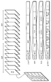
도 1은 비트스트림의 일 예의 데이터 구조를 나타내는 다이어그램이다. 도 1에 나타낸 것같이, 비트스트림은 다음과 같이 계층 구조를 갖는다. 비트스트림(스트림)은 하나 이상의 GOP(group of picture)로 형성되어 있다. 기본 부호화 단위로서 GOP를 이용하여, 임의로 액세스할 뿐아니라 동화상을 편집하는 것도 가능하게 된다. 각각의 GOP는 복수의 픽쳐로 이루어지고, 각각은 I 픽쳐, P 픽쳐, B 픽쳐중 하나이다. 또한 각 픽쳐는 복수의 슬라이스로 이루어진다. 각 픽쳐내의 스트립형의 영역인 각 슬라이스는 복수의 매크로블록으로 이루어진다. 또한, 각 스트림, GOP, 픽쳐 및 슬라이스는 각 단위의 엔딩 포인트를 나타내는 동기 신호(sync)와 상기 각 단위에 공통인 데이터인 헤더(header)를 포함한다.1 is a diagram illustrating an example data structure of a bitstream. As shown in Fig. 1, the bitstream has a hierarchical structure as follows. The bitstream (stream) is formed of one or more group of pictures (GOP). By using the GOP as the basic coding unit, it is possible not only to arbitrarily access but also to edit a moving image. Each GOP consists of a plurality of pictures, each of which is one of an I picture, a P picture, and a B picture. Each picture is composed of a plurality of slices. Each slice, which is a strip-shaped area in each picture, consists of a plurality of macroblocks. In addition, each stream, GOP, picture, and slice includes a sync signal representing the ending point of each unit and a header which is data common to each unit.
데이터가 스트림 시퀀스인 비트 스트림에서 전송되지 않고, 조각 단위인 패킷등으로 전송되는 경우, 헤더와, 헤더 이외의 부분인 데이터부는 분리되어 전송될 수 있다. 이러한 경우, 도 1에 나타낸 것같이 헤더 및 데이터 부가 동일한 비트 스트림에 조합되지 않는다. 그러나, 패킷의 경우에, 헤더 및 데이터부가 인접하여 송신되지 않을 때에도, 데이터부에 대응하는 헤더가 다른 패킷에서 전송되고 있는 것이다. 그러므로, 헤더 및 데이터 부가 동일한 비트 스트림에 조합되지 않을 때에도, 도 1을 참조하여 서술된 부호화된 비트스트림의 개념은 또한 패킷으로 응용가능하다.When data is not transmitted in a bit stream that is a stream sequence but is transmitted in packets or the like that are fragments, the header and the data portion other than the header may be transmitted separately. In this case, the header and the data portion are not combined in the same bit stream as shown in FIG. However, in the case of a packet, even when the header and the data portion are not transmitted adjacently, the header corresponding to the data portion is transmitted in another packet. Therefore, even when the header and the data portion are not combined in the same bit stream, the concept of the coded bitstream described with reference to FIG. 1 is also applicable to a packet.
일반적으로, 사람의 시각적 감각은 고주파수 성분보다 저주파수 성분에 더 민감하다. 또한, 화상 신호에서 저주파수 성분의 에너지가 고주파수 성분 보다 크기 때문에, 화상 부호화가 저주파수 성분으로부터 고주파수 성분까지의 순서로 행해진다. 그 결과, 저주파수 성분의 부호화에 요구되는 비트의 수는 고주파수 성분에 대해서 요구되는 것보다 크다.In general, the human visual sense is more sensitive to low frequency components than to high frequency components. In addition, since the energy of the low frequency component in the image signal is larger than the high frequency component, image coding is performed in the order from the low frequency component to the high frequency component. As a result, the number of bits required for encoding of the low frequency component is larger than that required for the high frequency component.
상기 사항들을 고려하여, 직교 변환에 의해 각 주파수의 변환계수를 양자화할 때 얻어지는 현재의 부호화 방법은 고주파수 성분에 대해서 저주파수 성분보다 더 큰 양자화 단계를 사용한다. 이 기술은 종래의 부호화 방법이, 시청자의 입장에서 화상 품질의 손실이 작고, 압축비의 증가가 큰 것을 가능하게 한다.In view of the above, the current encoding method obtained when quantizing the transform coefficient of each frequency by orthogonal transform uses a quantization step larger than the low frequency component for the high frequency component. This technique enables the conventional coding method to have a small loss of image quality and a large increase in compression ratio from the viewer's point of view.
한편, 저주파수 성분에 대한 고주파수 성분의 양자화 단계 크기가 화상 신호에 의거하기 때문에, 각 주파수 성분에 대한 양자화 단계의 크기를 화상 단위로 변화시키기 위한 기술이 종래 사용되어 오고 있다. 각 주파수 성분의 양자화 단계를 도출하기 위해 양자화 매트릭스가 사용된다. 도 2는 양자화 매트릭스의 일예를 나타낸다. 이 도면에서, 상부 좌측 성분은 DC 성분인 반면, 우측 성분은 수평의 고주파수 성분이고, 하측 성분은 수직의 고주파수 성분이다. 도 2의 양자화 매트릭스는 또한 더 큰 값에 더 큰 양자화 단계가 적용된다는 것을 나타낸다. 통상, 각 화상에 대해서 다른 양자화 매트릭스를 사용하는 것이 가능하다. 각 주파수 성분의 양자화 단계의 크기를 나타내는 값은 고정 길이 부호화이다. 양자화 매트릭스의 각 성분 및 각 양자화 단계의 값은 대략 서로 비례하는 것이 일반적이지만, 그들 사이의 일치가 명백히 규정되어 있지 않는 한, 이러한 관계를 유지하는 것은 필요하지 않다. On the other hand, since the size of the quantization step of the high frequency component for the low frequency component is based on the image signal, a technique for changing the size of the quantization step for each frequency component in image units has been used conventionally. A quantization matrix is used to derive the quantization step of each frequency component. 2 shows an example of a quantization matrix. In this figure, the upper left component is a DC component, while the right component is a horizontal high frequency component, and the lower component is a vertical high frequency component. The quantization matrix of FIG. 2 also indicates that a larger quantization step is applied to larger values. Usually, it is possible to use different quantization matrices for each image. The value representing the magnitude of the quantization step of each frequency component is fixed length coding. It is common for the components of the quantization matrix and the values of each quantization step to be roughly proportional to each other, but it is not necessary to maintain this relationship unless the agreement between them is clearly defined.
그러나, 이러한 종래의 방법은 양자화 매트릭스의 각각의 주파수 성분의 값이 특정 범위에 집중된다는 사실에 의거하여 고정 길이 부호화를 단순히 행함으로써 부호화 효율이 저하된다는 문제를 가지고 있다.However, this conventional method has a problem that the encoding efficiency is lowered by simply performing fixed length encoding based on the fact that the value of each frequency component of the quantization matrix is concentrated in a specific range.
본 발명의 목적은, 양자화 매트릭스 부호화의 효율을 개선할 수 있는 화상 부호화 방법, 화상 복호화 방법, 화상 부호화 장치, 화상 복호화 장치 및 그 프로그램을 제공하는 것이다.An object of the present invention is to provide a picture coding method, a picture decoding method, a picture coding apparatus, a picture decoding apparatus and a program thereof which can improve the efficiency of quantization matrix coding.
상기 목적을 달성하기 위해, 본 발명에 따른 화상 부호화 방법은 직교변환 및 양자화를 통하여 블록 단위로 화상을 부호화하고, 직교 변환 계수의 주파수에 대한 양자화 단계를 도출하기 위해 사용되는 양자화 매트릭스를 부호화하는 화상 부호화 방법으로서, 양자화 매트릭스에 포함된 각 주파수 성분과 상기 각각의 주파수 성분에 대응하는 소정 값 사이의 차이 값을 계산하는 단계; 및 상기 차이 값을 가변 길이 부호로 부호화하는 단계를 포함하고, 상기 가변 길이 부호의 부호 길이는, 상기 차이 값이 더 작아짐에 따라 짧아 지거나, 상기 차이 값의 인접하는 차이 값의 부호 길이와 같다.In order to achieve the above object, an image encoding method according to the present invention encodes an image in units of blocks through orthogonal transform and quantization, and encodes a quantization matrix used to derive a quantization step for a frequency of orthogonal transform coefficients. An encoding method, comprising: calculating a difference value between each frequency component included in a quantization matrix and a predetermined value corresponding to each frequency component; And encoding the difference value with a variable length code, wherein the code length of the variable length code is shortened as the difference value becomes smaller, or is equal to the code length of an adjacent difference value of the difference value.
상기 구성으로, 각 주파수 성분 및 소정 값 사이의 차이 값이 계산되므로, 결과의 차이 값은 주파수 성분보다 더 작고, 주파수 성분이 아니라 차이 값이 부호화되므로, 각 가변 길이 부호의 부호 길이를 짧게 할 수 있고, 그러므로 부호화 효율을 개선시킨다.With the above configuration, since the difference value between each frequency component and the predetermined value is calculated, the difference value of the result is smaller than the frequency component and the difference value is encoded rather than the frequency component, so that the code length of each variable length code can be shortened. Therefore, the coding efficiency is improved.
여기서, 소정 값은 직전의 차이 값에 대응하는 주파수 성분의 값일 수 있다.Here, the predetermined value may be a value of a frequency component corresponding to the difference value just before.
상기 구성으로, 주파수 성분과 이전 주파수 성분 사이에 통상적으로 상관이 있으므로, 각 차이 값은 더 작은 값을 취할 수 있으므로 부호화 효율을 더 개선시킬수 있다.With the above configuration, since there is usually a correlation between the frequency component and the previous frequency component, each difference value can take a smaller value, thereby further improving the coding efficiency.
여기서, 차이 값은 양자화 매트릭스에 포함된 주파수 성분의 저주파수로부터 고주파수까지의 순서로 계산될 수 있다.Here, the difference value may be calculated in the order from the low frequency to the high frequency of the frequency component included in the quantization matrix.
상기 구성으로, 주파수 성분은 저주파수로부터 고주파수까지 계산되므로, 각 주파수 성분 및 이전 주파수 성분이 유사한 값을 취하는 것이 매우 가능하다. 그러므로, 각 차이 값이 보다 신뢰성 있는 방식으로 더 유사한 값을 취하는 것이 가능하게 되므로, 부호화 효율을 더 개선시킬수 있다.With this configuration, since the frequency component is calculated from the low frequency to the high frequency, it is very possible that each frequency component and the previous frequency component take similar values. Therefore, since it is possible for each difference value to take a more similar value in a more reliable manner, the coding efficiency can be further improved.
여기서, 각각의 차이 값은 2의 k 제곱의 나머지로서 나타내진다.Here, each difference value is represented as the remainder of k square of two.
상기 구성으로, 각 차이 값이, 각 차이 값을 2의 k(k=8) 제곱의 나머지로서 나눈 결과의 나머지로서 표현되는 경우, 실제적으로 8비트로 표현될 수 있는 작은 값을 취하는 것이 가능하게 되므로, 가변 길이 부호 비트의 수를 더 줄일 수 있다.With the above configuration, when each difference value is represented as the remainder of the result of dividing each difference value by the remainder of k (k = 8) squares of 2, it is possible to take a small value that can be represented in practically 8 bits. Therefore, the number of variable length code bits can be further reduced.
여기서, 상기 화상 부호화 방법은 양자화 매트릭스의 후부에 대응하는 연속적인 차이 값 0이 존재하는지 아닌지를 판단하는 단계; 및 연속적인 차이 값 0이 존재한다고 판단할 때, 연속적인 차이 값 0을 가변 길이 부호로 부호화하지 않고, 탑의 차이 값 0의 직전까지의 차이 값들을 가변 길이 부호로 부호화하는 단계를 더 포함할 수 있다.The image encoding method may include determining whether or not a
여기서, 상기 화상 부호화 방법은 탑의 차이 값 0의 직전의 차이 값의 가변 길이 부호 뒤에 엔드 코드를 부가하는 단계를 더 포함할 수 있다.Here, the image encoding method may further include adding an end code after the variable length code of the difference value immediately before the
상기 구성으로, 양자화 매트릭스의 마지막에 동일 값을 갖는 연속적인 주파수 성분이 있는 경우, 동일한 비트 스트림을 갖는 복수의 가변 길치 부호화를 생성하기 보다는, 이러한 복수의 주파수 성분에 대해서 단지 하나의 가변 길이 부호가 생성된다. 따라서, 부호화 효율을 더 개선시킬 수 있게 된다. 이 경우, 엔드 코드를 부가함으로써, 화상 복호화 장치에 의해 행해진 복호화의 효율을 또한 개선시킬 수 있다.With the above configuration, if there are consecutive frequency components having the same value at the end of the quantization matrix, only one variable length code is added for these multiple frequency components, rather than generating a plurality of variable length codings having the same bit stream. Is generated. Thus, the coding efficiency can be further improved. In this case, by adding the end code, the efficiency of the decoding performed by the image decoding device can be further improved.
또한, 상기 목적을 달성하기 위해, 본 발명에 따른 화상 복호화 방법은 역양자화 및 역직교변환을 통하여 블록 단위로 부호화된 화상을 복호화하고, 가변 길이 부호화된 양자화 매트릭스를 복호화하는 화상 복호화 방법으로서, 상기 양자화 매트릭스를, 상기 양자화 매트릭스에 포함된 각 주파수 성분에 대응하는 차이 값으로 가변 길이 복호화하는 단계; 및 상기 차이 값을 상기 각 주파수 성분에 대응하는 소정 값에 가산함으로써 양자화 매트릭스의 각 주파수 성분을 계산하는 단계를 포함하고, 상기 가변 길이 부호의 부호 길이는, 상기 차이 값이 더 작아짐에 따라 짧아 지거나, 상기 차이 값의 인접하는 차이 값의 부호 길이와 같다.In addition, in order to achieve the above object, the picture decoding method according to the present invention is a picture decoding method for decoding a picture coded in units of blocks through inverse quantization and inverse orthogonal transformation, and decodes a variable length coded quantization matrix, Variable length decoding the quantization matrix into a difference value corresponding to each frequency component included in the quantization matrix; And calculating each frequency component of the quantization matrix by adding the difference value to a predetermined value corresponding to each frequency component, wherein the code length of the variable length code is shortened as the difference value becomes smaller. Is equal to the sign length of adjacent difference values of the difference values.
여기서, 소정 값은 직전의 가산에 의해 계산된 주파수 성분의 값일 수 있다.Here, the predetermined value may be a value of the frequency component calculated by the previous addition.
여기서, 가산은 양자화 매트릭스에 포함된 주파수 성분의 저주파수로부터 고주파수까지의 순서로 실행될 수 있다.Here, the addition may be performed in order from the low frequency to the high frequency of the frequency components included in the quantization matrix.
여기서, 각각의 주파수 성분은 2의 k(k는 상수) 제곱의 나머지로서 나타내질 수 있다.Here, each frequency component can be represented as the remainder of k (k is a constant) square of two.
상기 구성으로, 상기 부호화 방법을 통해 부호화 효율을 개선할 수 있는 가변 길이 비트 스트링을 쉽게 복호화하게 된다.With this arrangement, the variable length bit string can be easily decoded through the encoding method.
여기서, 가변 길이 부호화된 양자화 매트릭스로부터 엔드 코드가 검출되는 경우, 엔드 코드의 직전 주파수 성분의 값과 동일한 값이 후속하는 주파수 성분의 각각의 값으로서 출력될 수 있다.Here, when the end code is detected from the variable length coded quantization matrix, a value equal to the value of the immediately preceding frequency component of the end code may be output as each value of the subsequent frequency component.
상기 구성으로, 양자화 매트릭스의 마지막에 동일 값을 갖는 연속적인 주파수 성분이 있는 경우, 모든 이러한 복수의 주파수 성분을 얻도록 단지 하나의 가변 길이 부호를 복호화할 수 있게 된다. 또한, 엔드 코드는 양자화 매트릭스의 마지막에 동일 값을 갖는 연속적인 주파수 성분이 있는지를 쉽게 판단하게 된다.With this configuration, it is possible to decode only one variable length code to obtain all such a plurality of frequency components when there are consecutive frequency components having the same value at the end of the quantization matrix. In addition, the end code easily determines whether there is a continuous frequency component having the same value at the end of the quantization matrix.
본 발명에 따른 화상 부호화 장치, 화상 복호화 장치 및 그 프로그램도 또한 상기와 같은 효과 뿐만 아니라 동일한 구성을 가진다.The picture coding apparatus, the picture decoding apparatus and the program thereof according to the present invention also have the same configuration as well as the above effects.
본 발명은 동화상을 배송하는 웹서버뿐 아니라, 화상을 부호화하는 부호화장치, 화상을 복호하는 복호화장치, 이러한 동화상을 수신하는 네트워크 단말, 동화상을 기록 및 재생할 수 있는 디지털 카메라, 카메라 장착 휴대폰, DVD 레코더/플레이어, PDA, 개인용 컴퓨터 등으로서 사용하는데 적합하다.The present invention is not only a web server for delivering moving images, but also an encoding apparatus for encoding an image, a decoding apparatus for decoding an image, a network terminal for receiving such a moving image, a digital camera capable of recording and playing back moving images, a mobile phone with a camera, a DVD recorder. Suitable for use as a player, PDA, personal computer, etc.
본 발명의 이들 및 다른 목적, 장점 및 특징은 본 발명의 특정 실시예를 도시하는 첨부 도면과 연결하여 취해진 다음의 설명으로부터 분명해질 것이다. 도면에서,
도 1은 비트 스트림의 데이터 구조의 일예를 나타내는 다이어그램이다.
도 2는 양자화 매트릭스의 일 예를 나타내는 다이어그램이다.
도 3은 화상 부호화 장치의 구성을 나타내는 블록도이다.
도 4는 WM 부호화부의 구성을 나타내는 블록도이다.
도 5a ~ 도 5d는 양자화 매트릭스의 순서를 각각 나타내는 다이어그램이다.
도 6a는 양자화 매트릭스의 성분 값의 구체적인 예를 나타내는 다이어그램이다.
도 6b는 양자화 매트릭스를 부호화하는 처리에서 차이 값의 구체적인 예를 나타내는 다이어그램이다.
도 6c는 주파수 성분으로부터 차이 값을 계산하고, 가변 길이 부호를 부호화하는 처리를 통한 부호의 구체적인 예를 나타내는 다이어그램이다.
도 7은 WM 부호화부에 의해 실행된 부호화 처리를 나타내는 플로우 챠트이다.
도 8a는 차이 값이 양인 경우에 가변 길이 부호의 구체적인 예를 나타내는 다이어그램이다.
도 8b는 차이 값이 부호붙인(signed) 값인 경우에 가변 길이 부호의 구체적인 예를 나타내는 다이어그램이다.
도 8c는 가변 길이 부호화의 구체적인 예를 나타내는 다이어그램이다.
도 9a는 양자화 매트릭스의 주파수 성분의 구성을 나타내는 다이어그램이다.
도 9b ~ 도 9c는 양자화 매트릭스의 주파수 성분의 각각의 부호화된 데이터가 어떻게 헤더에 배열되는지를 나타내는 다이어그램이다.
도 10은 화상 복호화 장치의 구성을 나타내는 블록도이다.
도 11은 WM 복호화부의 구성을 나타내는 블록도이다.
도 12는 WM 복호화부에 의해 실행된 처리를 나타내는 플로우챠트이다.
도 13a ~ 도 13c는 상기 실시예에 따른 화상 부호화 방법 및 화상 복호화 방법을 컴퓨터 시스템에 의해 실현하는 프로그램을 저장하는 기록 매체를 나타내는 다이어그램이다.
도 14는 컨텐츠 공급 시스템의 전체적인 구성을 나타내는 블록도이다.
도 15는 화상 부호화 방법 및 화상 복호화 방법을 이용하는 휴대폰의 외부도를 나타내는 다이어그램이다.
도 16은 휴대폰의 구성을 나타내는 블록도이다.
도 17은 디지털 방송 시스템의 전체적인 구성을 나타내는 다이어그램이다.These and other objects, advantages and features of the present invention will become apparent from the following description taken in conjunction with the accompanying drawings which illustrate certain embodiments of the invention. In the drawings,
1 is a diagram illustrating an example of a data structure of a bit stream.
2 is a diagram illustrating an example of a quantization matrix.
3 is a block diagram showing the structure of a picture coding apparatus.
4 is a block diagram showing a configuration of a WM encoder.
5A to 5D are diagrams showing the order of the quantization matrix, respectively.
6A is a diagram illustrating a specific example of component values of a quantization matrix.
6B is a diagram illustrating a specific example of difference values in a process of encoding a quantization matrix.
6C is a diagram showing a concrete example of a code through a process of calculating a difference value from a frequency component and encoding a variable length code.
7 is a flowchart showing an encoding process executed by the WM encoder.
8A is a diagram illustrating a specific example of the variable length code when the difference value is positive.
8B is a diagram illustrating a specific example of the variable length code when the difference value is a signed value.
8C is a diagram illustrating a specific example of variable length coding.
9A is a diagram showing the configuration of frequency components of a quantization matrix.
9B-9C are diagrams showing how each encoded data of frequency components of a quantization matrix is arranged in a header.
10 is a block diagram showing the configuration of a picture decoding apparatus.
11 is a block diagram showing the configuration of a WM decoder.
12 is a flowchart showing processing executed by the WM decoding unit.
13A to 13C are diagrams showing a recording medium storing a program for realizing a picture coding method and a picture decoding method according to the embodiment by a computer system.
14 is a block diagram showing the overall configuration of a content supply system.
15 is a diagram showing an external view of a mobile phone using the picture coding method and the picture decoding method.
Fig. 16 is a block diagram showing the structure of a mobile phone.
17 is a diagram showing the overall configuration of a digital broadcasting system.
(제1 실시예)(First embodiment)
도 3 ~ 도 17을 참조하여, 본 발명의 제1 실시예를 서술한다.3 to 17, a first embodiment of the present invention will be described.
도 3은 본 발명의 제1 실시예에 따른 화상 부호화 장치의 제1 실시예의 구조를 나타내는 블록도이다.Fig. 3 is a block diagram showing the structure of the first embodiment of the picture coding apparatus according to the first embodiment of the present invention.
화상 부호화 장치(1)는 입력 화상 신호(Vin)를 압축하여, 가변 길이 부호화 등을 행함으로써 비트 스트림으로 부호화된 부호화 화상 신호(Str)를 출력하는 장치이다. 이러한 화상 부호화 장치(1)는 움직임 추정부(ME), 움직임 보상부(MC), 감산부(Sub), 직교 변환부(T), 양자화부(Q), 역양자화부(IQ), 역직교변환부(IT), 가산부(Add), 픽쳐 메모리(PicMem), 스위치(SW) 및 가변 길이 부호화부(VLC)로 구성되어 있다.The
화상신호(Vin)가 감산부(Sub) 및 움직임 추정부(ME)로 입력된다. 감산부(Sub)는 입력 화상신호(Vin)의 각각의 이미지와 각 예측 이미지 사이의 잔차 이미지를 블록 단위로 계산하고, 계산된 잔차 이미지를 직교 변환부(T)에 출력한다. 직교 변환부(T)는 잔차 이미지를 주파수 계수로 변환하기 위해 직교 변환을 행하여, 양자화부(Q)에 출력한다.The image signal Vin is input to the subtraction unit Sub and the motion estimation unit ME. The subtraction unit Sub calculates the residual image between each image of the input image signal Vin and each prediction image in block units, and outputs the calculated residual image to the orthogonal transformation unit T. The orthogonal transform unit T performs orthogonal transform in order to convert the residual image into a frequency coefficient and outputs it to the quantization unit Q.
양자화부(Q)는 감산부(Sub)로부터 입력된 각 블록의 주파수 계수를 양자화 매트릭스(WM)를 참조하여 도출된 양자화 단계를 이용하여 양자화하고, 결과의 양자화 값(Qcoef)을 가변 길이 부호화부(VLC)에 출력한다.The quantizer Q quantizes the frequency coefficient of each block input from the subtractor Sub using the quantization step derived by referring to the quantization matrix WM, and converts the resultant quantization value Qcoef into a variable length encoder. Output to (VLC).
역양자화부(IQ)는 양자화 값(Qcoef)을 양자화 매트릭스(WM)를 참조하여 도출된 양자화 단계를 이용하여 역양자화를 행하여, 주파수 계수로 변환하도록 하고, 역직교 변환부(IT)에 출력한다. 역직교 변환부(IT)는 주파수 계수에 역주파수 변환을 행하여 잔차 이미지로 변환하도록 하여, 가산부(Add)에 출력한다. 가산부(Add)는 각각의 잔차 이미지와 움직임 추정부(ME)로부터 출력된 각각의 예측 이미지를 가산하여 복호화 화상을 형성한다. 이러한 복호화 화상이 저장되어야 하는 것을 나타낼 때, 및 이러한 복호화 화상이 픽쳐 메모리(PicMem)에 저장되어야 하는 것을 나타낼 때 스위치(SW)를 온으로 한다.The inverse quantization unit IQ dequantizes the quantization value Qcoef using the quantization step derived by referring to the quantization matrix WM, converts the quantization value Qcoef into a frequency coefficient, and outputs it to the inverse orthogonal transformation unit IT. . The inverse orthogonal transform unit IT performs an inverse frequency transform on the frequency coefficient to convert the residual image into a residual image, and outputs the result to the adder. An adder adds each residual image and each prediction image output from the motion estimation unit ME to form a decoded image. The switch SW is turned on when indicating that this decoded picture should be stored, and when indicating that this decoded picture should be stored in the picture memory PicMem.
한편, 화상 신호(Vin)를 매크로블록 단위로 수신하는 움직임 추정부(ME)는 픽쳐 메모리(PicMem)에 저장된 복호화 화상 중에서 이러한 입력 화상 신호(Vin)에 가장 가까운 화상 영역을 검출하고, 이러한 영역의 위치를 표시하는 움직임 벡터(MV)를 결정한다. 움직임 벡터는 매크로 블록을 더 분할함으로써 얻어진 각각의 블록에 대해서 추정된다. 이 때, 하나 이상의 픽쳐를 참조 픽쳐로서 사용할 수 있다. 여기서, 복수의 픽쳐가 참조 픽쳐로서 사용될 수 있으므로, 각각의 참조 픽쳐를 식별하기 위한 식별 번호(참조 인덱스(Index))가 블록 단위로 요구되고 있다. 참조 인덱스와 픽쳐 메모리(PicMem)에 저장된 각 픽쳐의 픽쳐 번호 사이의 대응은 참조 픽쳐가 표시되는 것을 가능하게 한다.Meanwhile, the motion estimation unit ME, which receives the image signal Vin in macroblock units, detects an image region closest to the input image signal Vin from the decoded images stored in the picture memory PicMem, The motion vector MV indicating the position is determined. A motion vector is estimated for each block obtained by further dividing the macro block. At this time, one or more pictures can be used as the reference picture. Since a plurality of pictures can be used as the reference picture, an identification number (reference index) for identifying each reference picture is required in units of blocks. The correspondence between the reference index and the picture number of each picture stored in the picture memory PicMem enables the reference picture to be displayed.
움직임 보상부(MC)는 상기 처리에서 검출된 움직임 벡터와 참조 인덱스(Index)에 기초하여 픽쳐 메모리(PicMem)에 저장된 복호화 화상 중에서 예측 화상으로서 최적의 화상을 독출한다. The motion compensator MC reads out an optimal picture as a predictive picture from the decoded pictures stored in the picture memory PicMem based on the motion vector and the reference index detected in the above process.
가변 길이 부호화부(VLC)는 각각의 양자화 매트릭스(WM), 양자화값(Qcoef), 참조 인덱스(Index), 및 움직임 벡터(MV)에 가변 길이 부호화를 행하여 부호화 스트림(Str)을 출력하도록 한다. 이를 위해, 가변 길이 부호화부(VLC)는 제1 부호화부와 제2 부호화부를 포함한다. 제1 부호화부(이후 "WM 부호화부"라고 칭한다)는 각각의 양자화 매트릭스(WM)에 가변 길이 부호화를 행하는 반면, 제2 부호화부는 양자화 매트릭스(WM) 이외의 데이터 즉, 각각의 양자화값(Qcoef), 참조 인덱스(Index), 및 움직임 벡터(MV)에 가변 길이 부호화를 행한다. WM 부호화부는 각각의 양자화 매트릭스의 각각의 주파수 성분과 이러한 주파수 성분에 대응하는 소정 값 사이의 차이 값을 계산하고, 이러한 계산된 차이를 가변 길이 부호로 부호화한다. 몇가지 예외를 제외하고, 차이 값이 작을 수록, 결과의 가변 길이 부호의 길이는 짧아진다.The variable length encoder VLC performs variable length coding on each quantization matrix WM, the quantization value Qcoef, the reference index, and the motion vector MV to output the encoded stream Str. To this end, the variable length encoder VLC includes a first encoder and a second encoder. The first encoder (hereinafter referred to as "WM encoder") performs variable length encoding on each quantization matrix WM, while the second encoder performs data other than the quantization matrix WM, i.e., each quantization value Qcoef. Variable length coding is performed on the reference index (Index) and the motion vector (MV). The WM encoder calculates a difference value between each frequency component of each quantization matrix and a predetermined value corresponding to this frequency component, and encodes the calculated difference with a variable length code. With a few exceptions, the smaller the difference, the shorter the length of the variable-length code of the result.
도 4는 WM 부호화부의 구성을 나타내는 블록도이다. 이 도면이 나타내는 것같이, WM 부호화부는 감산부(41), W 버퍼(42), 오프셋 결정부(43), 가산부(44), 블록 버퍼(45), 수 결정부(46) 및 엔드 코드 유지부(47), 스위치(48) 및 가변 길이 부호화부(49)로 구성되어 있다.4 is a block diagram showing a configuration of a WM encoder. As shown in this figure, the WM encoder includes a
감산부(41)는 양자화 매트릭스의 각각의 주파수 성분과 이러한 주파수 성분에 대응하는 소정 값 사이의 차이 값을 계산한다. 여기서, 소정 값은 대부분 빈번하게 발생하는 고주파수 성분의 값 또는 주파수 성분의 평균치를 나타내는 상수 또는 각 주파수 성분에 대해서 미리 결정된 값일 수 있다. 본 실시예에서, 미리 결정된 차이 값에 대응하는 주파수 성분값이 소정 값로서 사용된다. 이 경우, 감산부(41)는 외부로부터 입력된 현재 주파수 성분(W[i]) 및 W버퍼(42)에 보관된 이전 주파수 성분(W[i-1]) 사이의 차이 값을 계산한다. 주파수 성분(W[i]) 및 이전 주파수 성분(W[i-1]) 사이에 통상적으로 상관이 있기 때문에, 나중 차이 값은 더 작게 된다. "W[i]"는 부호화되는 부호화 순서의 i번째 주파수 성분인 것을 나타낸다.The
도 5a ~ 5d는 감산부(41)에 입력되는 양자화 매트릭스의 주파수 성분의 예시적인 순서를 각각 나타내는 다이어그램이다. 이들 순서는 감산부(41)에 입력되는 양자화 매트릭스가 스캔되는 스캔 순서를 나타낸다. 화상 부호화에서 직교 변환은 각각의 4 x 4 화소 또는 각각의 8 x 8 화소에 대해서 가장 빈번하게 행해진다. 이를 고려하여, 도 5a 및 5b는 4 x 4 화소의 일 예를 도시하고, 도 5c 및 5d는 8 x 8 화소의 일 예를 도시한다. 양자화 매트릭스에서 각각의 주파수 성분은 도 8a, 8b 및 8c에 나타낸 패턴중 하나에 따라서 개별적으로 부호화되므로, 도 5a 및 도 5c에 나타낸 것같이 부호화가 저주파수 성분으로부터 고주파수 성분까지 행해지는지 또는 도 5b 및 도 5d에 나타낸 것같이 수평적인 순서로 간단하게 행해지는지 상관없이 부호화 효율에 차이가 없다.5A to 5D are diagrams each showing an exemplary procedure of frequency components of the quantization matrix input to the
도 6a는 감산부(41)에 입력된 양자화 매트릭스의 몇몇 주파수 성분을 나타내는 다이어그램이다. 이 도면에 나타낸, W[0], W[1], W[2], W[3], …는 도 5b에 나타낸 부호화 순서이다. 6A is a diagram showing some frequency components of the quantization matrix input to the
W 버퍼(42)는 이전 주파수 성분(W[i-1])을 유지하는 버퍼이다. 부호화가 시작하기 전에, W 버퍼(42)는 DC 성분으로서 가장 전형적으로 사용되는 값을 초기값(W[-1])으로서 유지한다. 본 실시예에서, 8이 초기값 W[-1]으로서 사용된다. W버퍼(42)는 이전 주파수 성분 W[i-1]을 유지하는 대신에, 각각의 주파수 성분에 대응하는 소정 값(k)을 유지할 수 있다.The
오프셋 결정부(43)는 감산부(41)로부터 입력된 차이 값(W[i]-W[i-1])을 이 차이를 2의 k제곱(이 경우 k=8)으로 나눈 나머지로 변환하기 위해 사용되는 오프셋 값을 결정한다. 더 구체적으로, 오프셋 결정부(43)는 -256, 0, 256중에서 하나를 출력하므로, 오프셋 값을 (W[i]-W[i-1])에 가산한 결과가 -128과 127 사이의 값의 범위내에 속한다.The offset
가산부(44)는 감산부(41)로부터의 차이 값(W[i]-W[i-1])을 오프셋 결정부(43)로부터의 오프셋 값에 가산하여 차이 값 D[i]을 계산한다. "D[i]"는 부호화되는 부호화 순서에서 i번째 차이 값인 것을 나타낸다.The
도 6b는 가산부(44)에 의해 계산된 차이 값 D[i]의 일 예를 나타내는 다이어그램이다. 이 도면에서, 차이 값 D[0], D[1], D[2], D[3], …은 도 6a에 나타낸 주파수 성분 W[0], W[1], W[2], W[3], …에 각각 대응한다.6B is a diagram illustrating an example of the difference value D [i] calculated by the
블록 버퍼(45)는 하나의 양자화 매트릭스에 대응하는 하나의 블록과 동등한 가산부(44)로부터 입력된 차이 값 D[i]을 유지하는 버퍼이다. The
수 결정부(46)는 스캔 순서의 마지막에서(블록의 마지막에서) 연속적으로 존재하는 차이 값 0(W[i]-W[i-1]=0)의 수를 계수하고, 스위치를 제어하여, 블록 버퍼(45)에 유지된 D[0]~D[M]이 출력된다. 여기서, D[M]은 상기 연속적인 차이 값들 0중 탑(top) 차이 값 0의 이전 차이 값이다.The
엔드 코드 유지부(47)는 양자화 매트릭스의 가변 길이 부호의 끝을 나타내는 엔드 코드를 유지한다. 차이 값 D[i]이 될 수 없는 임의의 값은 엔드 코드로서 기능할 수 있다.The end
스위치(48)는 블록 버퍼(45)에 유지된 D[0]~D[M]이 출력되도록 "블록 버퍼 출력"을 선택하고, 엔드 코드 유지부(47)로부터 하나의 엔드 코드가 출력되도록 "엔드 코드 유지부 출력"을 선택한다. 즉, 스위치(48)는, 양자화 매트릭스의 탑 주파수 성분에 대응하는 차이 값 D[0]으로 시작하여 양자화 매트릭스의 마지막에 존재하는 연속적인 차이 값들 0의 이전 차이 값에서의 차이 값 D[M]까지의 차이 값; 및 하나의 엔드 코드를 출력한다. 수 결정부(46)에 의해 계수된 스캔 순서의 끝(블록의 마지막에서)에 존재하는 연속적인 차이 값 0(W[i]-W[i-1]=0)의 수가 0인 경우에는, 스위치(48)가 엔드 코드를 출력하지 않는다.The
결과적인 부호의 길이가 차이 값이 작아짐에 따라, 인접하는 차이 값과 같거나 그것보다 짧아지도록, 가변 길이 부호화부(49)는 스위치(48)를 통하여 블록 버퍼(45)로부터 입력된 차이 값 및 엔드 코드에 가변 길이 부호화를 행한다. As the length of the resultant code becomes smaller as the difference value becomes smaller, the variable
도 6c는 도 8c에 나타낸 부호를 이용하여 가변 길이 부호화부(49)에 의해 행해진 부호화의 결과의 부호의 구체적인 일 예를 나타내는 다이어그램이다. 도면에서, W[0] ~ W[4] 및 D[0] ~ D[4]는 도 6a 및 도 6b에 대응한다. 예를 들면, 차이 값이 0일 때 부호화 길이는 1비트가 되고, 차이 값이 1일 때 부호화 길이는 3비트가 되도록, 가변 길이 부호화부(49)는 부호화를 행한다. 이 예가 포함하는 것같이, 가변 길이 부호화부(49)에 의해 행해진 가변 길이 부호화의 결과, 차이 값이 더 작아지면서 부호 길이는 더 짧아진다. 또한, W[30] ~ W[63]의 모든 주파수 성분이 64의 동일 값을 취하는 경우, 이들 차이 값 D[30] ~ D[63]이 모두 0이 된다. 이 경우, 이들 차이 값 D[30] ~ D[63]에 대해서 부호화가 행해지지 않고, 차이 값 D[30]의 0에 대해서 부호 "1" 대신에 엔드 코드에 가변 길이 부호화가 행해진다.FIG. 6C is a diagram illustrating a specific example of the code of the result of the encoding performed by the
도 7은 양자화 매트릭스를 부호화하는 WM 부호화부에 의해 행해지는 상세한 부호화 처리를 나타내는 플로우챠트이다. 이 플로우챠트에서, "Num"은 양자화 매트릭스에서 주파수 성분의 수(예를 들면, 16, 64)를 나타내고, "i" 및 "j"는 0부터 (Num-1)까지 계수하기 위해 사용되는 변수를 나타낸다.7 is a flowchart showing the detailed encoding process performed by the WM encoding unit for encoding the quantization matrix. In this flowchart, "Num" represents the number of frequency components (eg, 16, 64) in the quantization matrix, and "i" and "j" are variables used to count from 0 to (Num-1). Indicates.
우선, WM 부호화부는 W버퍼(42)가 초기 값 W[-1](예를 들면, 8)을 유지하게 하여(S71), 루프 1로서 나타낸 처리를 통하여 양자화 매트릭스의 각 주파수 성분의 차이 값을 계산하고(S72 ~ S77), 결과의 차이 값을 블록 버퍼(45)에 저장한다. 그리고, WM 부호화부는 루프 2로서 나타낸 처리를 통하여 각 차이 값에 가변 길이 부호화를 행한다(S78 ~ S81).First, the WM encoder causes the
루프 1에서, 감산부(41)는 외부로부터 입력된 현재 주파수 성분(W[i]) 및 W버퍼(42)에 보관된 이전 주파수 성분(W[i-1]) 사이의 차이 값(D)을 계산한다. 오프셋 결정부(43)는 감산부(41)로부터 입력된 차이 값(D)을 이 차이 값(D)을 2의 k제곱(이 경우 k=8)으로 나눈 나머지로 변환하기 위해 사용되는 오프셋 값을 결정한다(S74). 예를 들면, W[i]가 -256 및 +254 사이의 범위의 값을 취하는 경우, 오프셋 결정부(43)는 다음을 결정한다: D가 128 이상일 때, 오프셋 값이 -256이어야 한다; D가 -128 보다 작을 때, 오프셋 값이 256이어야 한다; D가 상기 범위와 다른 값을 취하면 오프셋 값이 0이어야 한다. 그 결과, 오프셋 값을 D(예를 들면, D[i])에 가산하여 결정된 값은 양의 값뿐 아니라 음의 값도 포함되는 -128과 +127 사이의 범위 내에서 나머지가 된다.In
가산부(44)는 감산부(41)로부터의 차이 값 D(=W[i]-W[i-1])을 오프셋 결정부(43)로부터의 오프셋 값에 가산하여 차이 값 D[i]을 계산한다(S75 및 S76).The
루프 2에서, 수 결정부(46)는 D[i] 열의 마지막에 존재하는 연속적인 차이 값 0의 수를 결정하고, 이러한 연속적인 차이 값 0의 이전 차이 값인 차이 값 D[M]까지의 차이 값에 대해서 스위치(48)를 "블록 버퍼 출력"에 연결하고, 다음 스위치(48)를 "엔드 코드 유지부 출력"에 연결한다.In
가변 길이 부호화부(49)는 스위치(48)를 통하여 블록 버퍼(45)로부터 입력된 차이 값 D[i] 및 스위치(48)를 통하여 엔드 코드 유지부(47)로부터 입력된 엔드 코드를 부호화한다. 엔드 코드는 D[i]에 의해 취해질 수 없는 임의의 값을 취할 수 있으므로, 여기서 엔드 코드는 -W[M] 즉, W[M]=0이다. 이것은, 양자화 매트릭스의 주파수 성분이 양의 값이므로 "W[M]=0"을 만족하는 값이 엔드 코드로서 식별될 수 있기 때문이다.The variable
도 8a~8c는 가변 길이 부호화부(49)에 의해 행해지는 가변 길이 부호화의 일 예를 각각 나타내는 다이어그램이다. Exponential Golomb code가 이들 실시예에서 사용된다.8A to 8C are diagrams each showing an example of variable length coding performed by the variable
도 8a는 가변 길이 부호의 일 예를 나타낸다. 이 도면은 코드 워드(코드) 및 부호화 되기 전의 차이 값(값) 사이의 관계를 나타낸다. 이 예는 차이 값이 양의 값을 취할 수 있는 경우에 적용된다. 차이 값이 더 클 수록, 발생하는 빈도수는 더 작고, 그들 부호 길이는 더 길어지는 반면, 차이 값이 더 작을수록, 그들 코드 워드의 길이는 더 짧아진다. 각 성분의 값을 코드 워드로 변환하는 것은 도 8a에 표시된 산술 계산식을 이용하여 쉽게 행해질 수 있다. 예를 들면, 차이 값이 7일 때, 7=4+3(2의 2승 + 이진수 "11")으로 표현된다. 이 차이 값 7에 대한 코드 워드가 "000(3개의 0)", "1" 및 "11"로 구성된 비트 스트링으로 표현된다. 도 8a에서 "N"은 각 차이 값을 넘지 않는 가장 가까운 2의 지수를 나타낸다. "X1X2 …XN -1"은 각 차이 값으로부터 2의 가장 가까운 지수를 감산한 결과의 값을 나타내는 비트 스트링을 나타낸다.8A shows an example of a variable length code. This figure shows the relationship between the code word (code) and the difference value (value) before being encoded. This example applies when the difference value can take a positive value. The larger the difference value, the smaller the frequency of occurrence and the longer their code length, while the smaller the difference value, the shorter the length of those code words. The conversion of the value of each component into a code word can be easily done using the arithmetic formula shown in Fig. 8A. For example, when the difference value is 7, it is represented by 7 = 4 + 3 (2 power of 2 + binary "11"). The code word for this
도 8b는 가변 길이 부호화의 제2 예를 나타낸다. 이 도면에서, 칼럼 값은 양자화 매트릭스의 주파수 성분 W[i](즉, 소정 값 K + 차이 값)을 서술한다. 이 예는 양자화 매트릭스의 각 주파수 성분 W[i]의 값이 소정 값(K)을 취하기가 가장 쉬운 경우에 적용가능하다. 소정 값(K)의 발생 빈도가 높기 때문에, 주파수 성분의 값이 K일 때 부호 길이는 가장 짧게 되고, 주파수 성분의 값이 K로부터 떨어져 있으면 부호화 길이는 더 길게 된다. 소정 값(K)은 예를 들면 W[i-1]이거나, 다른 미리 결정된 상수이다.8B shows a second example of variable length coding. In this figure, the column value describes the frequency component W [i] (ie, the predetermined value K + difference value) of the quantization matrix. This example is applicable when the value of each frequency component W [i] of the quantization matrix is easiest to take a predetermined value K. Since the frequency of occurrence of the predetermined value K is high, the code length is shortest when the value of the frequency component is K, and the coding length is longer when the value of the frequency component is away from K. The predetermined value K is for example W [i-1] or another predetermined constant.
도 8c는 가변 길이 부호의 제3 예를 나타낸다. 이 도면은 코드 워드(코드) 및 부호화되기 전의 차이 값(값) 사이의 관계를 나타낸다. 이 예는 차이 값이 양의 값뿐 아니라 음의 값을 취하는 경우에 적용 가능하다. 양자화 매트릭스의 각 성분이 도 5a ~ 도 5d중 하나에 나타낸 순서로 부호화될 때, 인접하는 주파수 성분의 값 W[i-1]이 밀접하게 관련된다. 그래서, 미리 부호화된 성분 값 W[i] 및 현재 성분 값 W[i] 사이의 차이 값을 도 5a ~5d중 하나에 나타낸 순서로 부호화하여, 결과의 차이 값은 0의 주위에 집중된다. 그래서, 짧은 부호 길이를 갖는 코드 워드를 0 근처의 값에 할당하고, 도 8c에 나타낸 것같이 0으로부터 먼 값에 더 긴 부호 길이를 갖는 코드 워드를 할당함으로써, 가변 길이 부호 비트의 수를 더 줄이는 것이 가능하게 된다. 8C shows a third example of variable length code. This figure shows the relationship between the code word (code) and the difference value (value) before being encoded. This example is applicable when the difference value takes a negative value as well as a positive value. When each component of the quantization matrix is encoded in the order shown in one of Figs. 5A to 5D, the values W [i-1] of adjacent frequency components are closely related. Thus, the difference value between the pre-encoded component value W [i] and the current component value W [i] is encoded in the order shown in one of Figs. 5A to 5D, and the resulting difference value is concentrated around zero. Thus, by assigning a code word with a short code length to a value near zero and assigning a code word with a longer code length to a value far from zero as shown in FIG. 8C, the number of variable length code bits is further reduced. It becomes possible.
도 9a 내지 9c는 양자화 매트릭스 및 스트림에서 양자화 매트릭스의 데이터 구조를 나타내는 다이어그램이다. 도 9b 및 9c에서, "헤더"는 도 1에 나타낸 스트림/GOP/픽쳐의 헤더와 동일하다. 도 9a는 양자화 매트릭스의 주파수 성분의 구성을 나타내는 다이어그램이다. 도면에서, "Wi,j"는 i번째 라인에서의 j번째 열의 양자화 매트릭스의 성분을 나타낸다. 도 9b 및 9c는 양자화 매트릭스의 각 성분을 부호화함으로써 얻어진 각 데이터가 헤더에 어떻게 배열되는지를 도시한다. "가중매트릭스"는 양자화 매트릭스를 부호화함으로써 얻어진 비트스트림을 표현한다. 도 9b는 도 5c에 나타낸 순서로 부호화를 행함으로써 얻어진 스트림을 나타내는 반면, 도 9c는 도 5d에 나타낸 순서로 부호화를 행함으로써 얻어진 스트림을 나타낸다. 도 9b 및 9c에 나타낸 스트림에서 "Wi,j"는 도 9a에 나타낸 Wi,j에 대응하는 부호화된 가변 길이 부호인 것을 나타낸다.9A-9C are diagrams illustrating the data structures of quantization matrices in quantization matrices and streams. In FIGS. 9B and 9C, the "header" is the same as the header of the stream / GOP / picture shown in FIG. 9A is a diagram showing the configuration of frequency components of a quantization matrix. In the figure, "Wi, j" represents the component of the quantization matrix of the jth column in the i-th line. 9B and 9C show how each data obtained by encoding each component of the quantization matrix is arranged in a header. "Weight matrix" represents a bitstream obtained by encoding a quantization matrix. Fig. 9B shows a stream obtained by encoding in the order shown in Fig. 5C, while Fig. 9C shows a stream obtained by encoding in the order shown in Fig. 5D. In the streams shown in Figs. 9B and 9C, " Wi, j " indicates that the encoded variable length code corresponds to Wi, j shown in Fig. 9A.
상기 서술된 것같이, 본 발명에 따르는 WM 부호화부는 주파수 성분 W[i]과 소정 값(K) 사이의 차이 값 D[i]을 결정하고, 차이 값 D[i]은 주파수 성분 W[i] 보다 작은 값을 취한다. 또한, WM 부호화부는 주파수 성분 W[i] 자체가 아니라 각 차이 값 D[i]을 부호화하기 때문에, 각 가변길이코드의 부호 길이를 짧게 할 수 있게 되고, 그러므로 부호화 효율을 개선시킬 수 있다.As described above, the WM encoder according to the present invention determines the difference value D [i] between the frequency component W [i] and the predetermined value K, and the difference value D [i] is the frequency component W [i]. Take a smaller value. Further, since the WM encoder encodes each difference value D [i] rather than the frequency component W [i] itself, the code length of each variable length code can be shortened, thereby improving the coding efficiency.
또한, 이전 주파수 성분 W[i-1]을 소정 값(K)으로서 사용하는 것은 각 차이 값 D[i]이 유사한 값을 취할 수 있게 하므로, 부호화 효율이 더 개선된다. 이것은 각 주파수 성분 W[i]과 이전 주파수 성분 W[i-1] 사이에 일반적으로 상관이 있기 때문이다. Also, using the previous frequency component W [i-1] as the predetermined value K allows each difference value D [i] to take a similar value, so that the coding efficiency is further improved. This is because there is a general correlation between each frequency component W [i] and the previous frequency component W [i-1].
더욱이, 주파수 성분 W[i]은 저주파수에서 고주파수 순서로 부호화되기 때문에, 각 주파수 성분 W[i]과 이전 주파수 성분 W[i-1]이 유사한 값을 취할 가능성이 매우 높다. 그러므로, 각 차이 값 D[i]이 더 유사한 값을 더 신뢰성 있는 방법으로 취하는 것이 가능하게 되고, 그 결과 부호화 효율이 더 개선된다.Moreover, since the frequency component W [i] is encoded in low-frequency order, it is highly likely that each frequency component W [i] and the previous frequency component W [i-1] take similar values. Therefore, it is possible for each difference value D [i] to take a more similar value in a more reliable manner, and as a result, the coding efficiency is further improved.
또한, 각 차이 값 D[i]이 각 차이 값을 2의 k승(k=8)으로 나눈 결과인 나머지로서 표현되는 경우, 실제적으로 8비트로 표현될 수 있는 작은 값을 취하므로, 가변 길이 부호 비트의 수를 더 줄일 수 있게 된다.In addition, when each difference value D [i] is represented as the remainder that is the result of dividing each difference value by the power of k (k = 8) of 2, the variable length code is actually taken because it takes a small value that can be represented by 8 bits. The number of bits can be further reduced.
더욱이, 양자화 매트릭스의 마지막에 동일한 값을 갖는 연속적인 주파수 성분이 있는 경우, 동일한 비트 스트링을 갖는 복수의 가변 길이 부호를 생성하지 않고, 이러한 복수의 주파수 성분에 대해서 가변길이 코드는 생성되지 않는다. 따라서, 부호화 효율을 더 개선시킬수 있게 된다. 이 경우, 엔드 코드를 부가함으로써, 화상 복호화 장치에 의해 실행된 복호화의 효율을 또한 개선할 수 있게 된다.Moreover, when there are consecutive frequency components having the same value at the end of the quantization matrix, a plurality of variable length codes having the same bit string are not generated, and a variable length code is not generated for these plurality of frequency components. Therefore, the coding efficiency can be further improved. In this case, by adding the end code, the efficiency of the decoding executed by the picture decoding apparatus can also be improved.
도 10은 본 발명의 제1 실시예에 따른 화상 복호화장치의 구성을 나타내는 블록도이다. 이 도면에서, 도 3에 나타낸 화상 부호화 장치의 요소와 동일한 방법으로 동작하는 요소는 동일한 숫자를 할당하고, 그 설명은 생략한다.10 is a block diagram showing the configuration of an image decoding apparatus according to a first embodiment of the present invention. In this figure, elements that operate in the same manner as those of the picture coding apparatus shown in FIG. 3 are assigned the same numerals, and description thereof is omitted.
가변길이 복호화부(VLD)는 부호화된 스트림(Str)을 양자화 매트릭스(WM), 양자화 값(Qcoef), 참조 인덱스(Index), 및 움직임 벡터(MV)로 복호화한다. 이를 행하기 위해, 가변 길이 복호화부(VLD)는 제1 복호화부 및 제2 복호화부를 포함한다. 제1복호화부(이후 "WM 복호화부"라고 칭한다)는 각각의 부호화된 양자화 매트릭스(WM)에 대해서 가변 길이 복호화를 행하는 반면, 제2 복호화부는 부호화된 양자화 매트릭스(WM) 이외의 정보 즉, 각각의 부호화된 양자화 값(Qcoef), 참조 인덱스(Index), 및 움직임 벡터(MV)에 가변 길이 복호화를 행한다. WM 복호화부는 가변 길이 부호화된 양자화 매트릭스를 각 주파수 성분의 차이 값으로 가변 길이 복호화하고, 그 다음 각 결과의 차이 값을 그 주파수 성분에 대응하는 소정 값에 가산하여, 각 양자화 매트릭스의 주파수 성분을 결정한다. The variable length decoder VLD decodes the encoded stream Str into a quantization matrix WM, a quantization value Qcoef, a reference index, and a motion vector MV. To do this, the variable length decoder VLD includes a first decoder and a second decoder. The first decoder (hereinafter referred to as "WM decoder") performs variable length decoding on each encoded quantization matrix (WM), while the second decoder performs information other than the encoded quantization matrix (WM), i.e. Variable length decoding is performed on the encoded quantized value Qcoef, the reference index Index, and the motion vector MV. The WM decoder performs variable length decoding on the variable length coded quantization matrix by the difference value of each frequency component, and then adds the difference value of each result to a predetermined value corresponding to the frequency component to determine the frequency component of each quantization matrix. do.
복호화는 픽쳐 메모리(PicMem), 움직임 보상부(MC), 및 역양자화부(IQ)을 통하여 각각의 양자화 매트릭스(QM), 양자화값(Qcoef), 참조 인덱스(Index), 및 움직임 벡터(MV)에 행해진다. 이 복호화는 도 3에 나타낸 화상 부호화 장치의 블록도를 참조하여 이미 위에 서술되어 있다.The decoding is performed through the picture memory PicMem, the motion compensator MC, and the inverse quantizer IQ, respectively, for the quantization matrix QM, the quantization value Qcoef, the reference index, and the motion vector MV. Is done. This decoding has already been described above with reference to the block diagram of the picture coding apparatus shown in FIG.
도 11은 WM 복호화부의 구성을 나타내는 블록도이다. 이 도면이 나타내는 것같이, WM 복호화부는 가변길이 복호화부(51), 가산부(52), 및 나머지 계산부(53), 스위치(54), W버퍼(55), 스위치(56) 및 엔드 계수 판정부(57)로 구성되어 있다.11 is a block diagram showing the configuration of a WM decoder. As shown in this figure, the WM decoding unit has a variable
가변 길이 복호화부(51)는 각각의 가변 길이 부호화된 주파수 성분의 가변 길이 부호를 차이 값 D[i]으로 복호화한다.The
가산부(52)는 가변 길이 복호화부(51)로부터의 각 차이 값 D[i]을 W버퍼(55)로부터의 이전 주파수 성분 W[i-1]에 가산한다.The
나머지 계산부(53)는 가산부(52)의 각 가산 결과를 2의 k승에 가산하고, 나머지를 구하기 위해 그 결과 값을 2의 k승으로 나눔으로써 각각의 주파수 성분 W[i]을 결정한다. 더 구체적으로, 나머지 계산부(53)는 (D[i]+W[i-1]+256)%256을 행한다. 여기서, "%"는 결과값을 256으로 나눠서 얻은 나머지를 결정하기 위한 연산을 나타낸다.The remaining
스위치(54)는 엔드 코드가 나머지 계산부(53)로부터 출력되지 않는 동안 온으로 하고, 엔드 코드가 출력된 후 오프로 한다.The
W버퍼(55)는 나머지 계산부(53)로부터 스위치(54)를 통해 입력된 주파수 성분 W[i]을 유지하고, 다음 주기에서 주파수 성분 W[i-1]으로서 가산부(52)에 출력한다. W버퍼(55)는 W[i-1](예를 들면, 8)을 초기 값으로서 더 유지한다.The
스위치(56)는 나머지 계산부(53)로부터 엔드코드가 출력되지 않는 동안, 스위치(54)를 통해 나머지 계산부(53)로부터 입력된 주파수 성분 W[i]을 계속해서 선택하고, 엔드 코드가 출력된 후 W버퍼(55)를 선택한다.The
엔드 계수 판정부(57)는 엔드 코드가 나머지 계산부(53)로부터 출력되었는지 판단하고, 이러한 판정에 기초하여 스위치(54) 및 스위치(56)를 제어한다.The end
상기 서술된 것같이, 모든 주파수 성분에 대응하여 W[i]를 복호화하는 것이 가능하다. 엔드 코드가 검출되지 않을 때에도, 양자화 매트릭스의 복호화는 블록에 포함된 모든 주파수 성분의 수와 동등한 수인 차이 값 D[i]의 복호화의 완료시 종료된다.As described above, it is possible to decode W [i] corresponding to all frequency components. Even when the end code is not detected, decoding of the quantization matrix ends upon completion of decoding of the difference value D [i] which is a number equivalent to the number of all frequency components included in the block.
도 12는 WM 복호화부에 의해 행해지는 처리를 나타내는 플로우챠트이다. 이 플로우 챠트에서, "Num"은 양자화 매트릭스에서 주파수 성분의 수(예를 들면, 16, 64)를 표시하고, "i"는 0부터 (Num-1)까지 계수하기 위해 사용되는 변수를 표시하고, "j"는 1부터 (Num-1)까지 계수하기 위해 사용되는 변수를 표시한다. 도 12에 나타내는 것같이, WM 복호화부는 처음에 W버퍼(55)가 초기값 W[i-1]을 유지하게 하고(S121), 가변 길이 복호화를 행하고, 루프 1로서 표시된 처리를 통하여 결과 코드를 출력하고(S122~S127), 엔드 코드가 검출된 후, 루프 2로서 나타낸 처리를 통하여 동일 값을 갖는 연속적인 주파수 계수를 출력한다.12 is a flowchart showing processing performed by the WM decoding unit. In this flowchart, "Num" denotes the number of frequency components (e.g., 16, 64) in the quantization matrix, "i" denotes the variable used to count from 0 to (Num-1) , "j" denotes a variable used to count from 1 to (Num-1). As shown in FIG. 12, the WM decoding unit firstly causes the
루프 1에서, 가변 길이 복호화부(51)는 입력된 가변 길이 부호를 차이 값 D[i]으로 복호화한다(S123). 그러면, 가산부(52)는 이전 주파수 성분에 가변길이 복호화부(51)로부터의 차이 값을 가산하고, 나머지 계산부(53)는 나머지(W)가 다음의 (S124): W=(D[i]+W[i-1]+256)%256을 만족하도록 계산을 행한다. 엔드 계수 판정부(57)는 이 나머지(W)가 엔드 코드인지 아닌지(여기서, 나머지(W)가 양 또는 음인지) 판단한다(S125). 엔드 계수 판정부(57)가 나머지(W)가 엔드 코드가 아니라고 판정할 때, 이러한 나머지(W)는 나머지 계산부(53)로부터 주파수 성분 W[i-1]으로서 출력되고, 동시에 스위치(54)를 통하여 W 버퍼(55)에 저장된다(S126). 한편, 엔드 계수 판정부(57)가 나머지(W)가 엔드 코드라고 판정할 때, 루프 2의 처리가 실행된다.In
루프 2에서, 양자화 매트릭스의 마지막에서 동일 값을 갖는 연속적인 주파수 성분이 있을 때, 주파수 성분 W[i-1]은 주파수 성분 W[i]으로서 연속적으로 출력된다. 더 구체적으로, W 버퍼(55)에 유지된 주파수 성분 W[i-1]은 스위치를 통하여 계속되는 주파수 성분 W[i]으로서 W[Num-1]로서 출력된다(S129).In
상기 서술된 것같이, 본 실시예에 따른 WM 복호화부는 WM 부호화부에 의해 차등 부호화된 가변 길이 부호를 정확하게 복호화한다. 더욱이, 양자화 매트릭스의 마지막에서 동일 값을 갖는 연속적인 주파수 성분이 있을 때, WM 복호화부는 모든 이러한 복수의 주파수 성분을 얻기 위해 단지 하나의 가변 길이 부호를 복호화하는 것만이 요구된다. 이 경우, 엔드 코드는 양자화 매트릭스의 마지막에서 동일 값을 갖는 연속적인 주파수 성분이 있는 것을 쉽게 판단하는 것을 가능하게 한다.As described above, the WM decoder according to the present embodiment correctly decodes the variable length code differentially coded by the WM encoder. Moreover, when there are successive frequency components with the same value at the end of the quantization matrix, the WM decoder only needs to decode one variable length code to obtain all such multiple frequency components. In this case, the end code makes it easy to determine that there is a continuous frequency component with the same value at the end of the quantization matrix.
또한, 상기 서술된 실시예에서 나타낸 것같은 화상 부호화방법 및 화상 복호화방법을 실현하는 프로그램이 플렉서블 디스크와 같은 기록매체에 기록되어 있으면, 별개의 컴퓨터 시스템에서 상기 실시예에 제시된 처리를 쉽게 행하는 것을 가능하게 한다.Further, if a program for realizing the picture coding method and the picture decoding method as shown in the above-described embodiment is recorded on a recording medium such as a flexible disk, it is possible to easily perform the processing shown in the above embodiment in a separate computer system. Let's do it.
도 13a, 13b 및 13c는 상기 서술된 실시예에 따른 화상 부호화방법 및 화상 복호화방법을 실현하는 프로그램을 저장하는 기록매체를 나타내는 다이어그램이다.13A, 13B and 13C are diagrams showing a recording medium storing a program for realizing the picture coding method and the picture decoding method according to the above-described embodiment.
도 13b는 플렉서블 디스크의 정면에서 본 외관, 단면도 및 플렉서블 디스크 자체를 나타내고, 도 13a는 기록매체인 플렉서블 디스크의 물리 포맷의 예를 나타내고 있다. 플렉서블 디스크(FD)는 케이스(F)내에 내장되고, 플렉서블 디스크의 표면에, 동심원상으로 외주로부터 반경방향으로 복수의 트랙(Tr)이 형성되어 있고, 각 트랙은 각도 방향으로 16 섹터(Se)로 분할되어 있다. 따라서, 상기 프로그램을 저장하는 플렉서블 디스크에서는, 이러한 프로그램으로서 화상 부호화 방법 및 화상 복호화 방법이 플렉서블 디스크(FD)상에 할당된 영역에 기록되어 있다.Fig. 13B shows an appearance, a sectional view and the flexible disc itself as seen from the front of the flexible disc, and Fig. 13A shows an example of the physical format of the flexible disc as a recording medium. The flexible disk FD is built in the case F, and a plurality of tracks Tr are formed on the surface of the flexible disk in the radial direction from the outer circumference concentrically, and each track has 16 sectors Se in the angular direction. It is divided into Therefore, in the flexible disk which stores the said program, the image coding method and the image decoding method are recorded in the area | region allocated on the flexible disk FD as such a program.
한편, 도 13c는 플렉서블 디스크(FD)상에 프로그램의 기록 및 재생을 행하기 위한 구성을 나타낸다. 상기 화상 부호화 방법 및 화상 복호화 방법을 실현하는 상기 프로그램을 플렉서블 디스크(FD)상에 기록할 때, 이러한 프로그램은 컴퓨터 시스템(Cs)을 이용하여 플렉서블 디스크 드라이브(FDD)를 통하여 기입된다. 한편, 플렉서블 디스크상의 프로그램에 의해 화상 부호화 방법 및 화상 복호화 방법이 컴퓨터 시스템(Cs)에 구축될 때, 프로그램은 플렉서블 디스크 드라이브(FDD)를 통하여 플렉서블 디스크(FD)로부터 독출되어, 컴퓨터 시스템(Cs)에 전송된다.On the other hand, Fig. 13C shows a configuration for recording and reproducing a program on the flexible disk FD. When the program for realizing the picture coding method and the picture decoding method is recorded on the flexible disk FD, such a program is written through the flexible disk drive FDD using the computer system Cs. On the other hand, when the picture coding method and the picture decoding method are built in the computer system Cs by the program on the flexible disk, the program is read out from the flexible disk FD via the flexible disk drive FDD, and the computer system Cs. Is sent to.
기록매체를 플렉서블 디스크로 가정하여 상기 설명을 행하였지만, 광디스크도 또한 이용될 수 있다. 또, 기록매체는 이것에 한하지 않고, IC 카드, ROM 카세트 등, 프로그램을 기록할 수 있는 다른 매체가 또한 이용될 수 있다.Although the above description has been made assuming that the recording medium is a flexible disk, an optical disk can also be used. In addition, the recording medium is not limited to this, and other media capable of recording a program, such as an IC card and a ROM cassette, may also be used.
다음은 상기 실시예에 나타낸 상기 화상 부호화 방법 및 화상 복호화 방법의 응용 예뿐 아니라 그것을 사용한 시스템을 설명한다.The following describes not only the application examples of the picture coding method and the picture decoding method shown in the above embodiments but also the systems using them.
도 14는 컨텐츠 배송 서비스를 실현하는 컨텐츠 공급 시스템(ex100)의 전체 구성을 나타내는 블록도이다. 통신 서비스의 제공 영역은 소망의 크기로 분할되고, 고정 무선국인 기지국(ex107~ex110)이 각 셀에 설치되어 있다. 14 is a block diagram showing an overall configuration of a content supply system ex100 for realizing a content delivery service. The area for providing communication service is divided into desired sizes, and base stations ex107 to ex110, which are fixed wireless stations, are provided in each cell.
이 컨텐츠 공급 시스템(ex100)에서, 컴퓨터(ex111), PDA(Personal Digital Assistant)(ex112), 카메라(ex113), 휴대폰(ex114) 및 카메라 장착 휴대폰(ex115)과 같은 장치는 각각 인터넷 서비스 프로바이더(ex102), 전화망(ex104) 및 기지국(ex107~ex110)을 통해 인터넷(ex101)에 연결된다.In this content supply system ex100, devices such as a computer ex111, a personal digital assistant (PDA) ex112, a camera ex113, a mobile phone ex114, and a camera-equipped mobile phone ex115 are each an Internet service provider ( ex102), telephone network ex104, and base stations ex107 to ex110 to connect to the internet ex101.
그러나, 컨텐츠 공급 시스템(ex100)은 도 14에 나타낸 것같은 조합에 한정되지 않고, 그들을 임의로 조합하여 연결될 수 있다. 또한, 각각의 장치는 고정 무선국인 기지국(ex107~ex110)을 통하지 않고, 전화망(ex104)에 직접 연결될 수 있다. However, the content supply system ex100 is not limited to the combination as shown in Fig. 14, and can be connected by arbitrarily combining them. Further, each device can be directly connected to the telephone network ex104 without going through the base stations ex107 to ex110 which are fixed wireless stations.
카메라(ex113)는 동화상을 촬영할 수 있는 디지털 비디오 카메라와 같은 장치이다. 휴대폰은 PDC(Personal Digital Communication) 시스템, CDMA(Code Division Multiple Access) 시스템, W-CDMA(Wideband-Code Division Multiple Access) 시스템, 또는 GSM(Global System for Mobile Communication) 시스템, PHS(Personal Handyphone System) 등의 휴대폰일 수 있고, 이들 중 임의의 하나이다.The camera ex113 is a device such as a digital video camera capable of shooting moving pictures. A mobile phone is a personal digital communication (PDC) system, a code division multiple access (CDMA) system, a wideband-code division multiple access (W-CDMA) system, a global system for mobile communication (GSM) system, a personal handyphone system (PHS), or the like. May be a mobile phone of any one of these.
더욱이, 스트리밍 서버(ex103)는 기지국(ex109) 및 전화망(ex104)을 통해 카메라(ex113)에 연결되어 있고, 카메라(ex113)를 이용하여 사용자에 의해 송신된 부호화된 데이터에 기초하여 라이브 배송 등을 가능하게 한다. 데이터 송신 처리가 가능한 카메라(ex113) 또는 서버 등은 촬영한 데이터를 부호화할 수 있다. 또한, 카메라(ex116)에 의해 촬영된 동화상 데이터는 스트리밍 서버(ex103)에 컴퓨터(ex111)를 통해 송신될 수 있다. 카메라(ex116)는 정지 화상 및 동화상을 촬영할 수 있는 디지털 카메라와 같은 장치이다. 이 경우, 카메라(ex116) 또는 컴퓨터(ex111)는 동화상 데이터를 부호화할 수 있다. 이 경우, 컴퓨터(ex111) 또는 카메라(ex116)에 포함된 LSI(ex117)는 부호화 처리를 행한다. 부호화 및 복호화를 행하는 소프트웨어는 컴퓨터(ex111) 등에 의해 판독가능한 기록 매체인 (CD-ROM, 플렉서블 디스크 및 하드 디스크와 같은) 특정 유형의 저장 매체에 조립될 수 있다. 또한, 카메라 장착 휴대폰(ex115)은 동화상 데이터를 송신할 수 있다. 이 동화상 데이터는 휴대폰(ex115)에 포함된 LSI에 의해 부호화된 데이터이다.Furthermore, the streaming server ex103 is connected to the camera ex113 through the base station ex109 and the telephone network ex104, and performs live delivery and the like based on the encoded data transmitted by the user using the camera ex113. Make it possible. The camera ex113 or the server capable of data transmission processing can encode the photographed data. Also, the moving image data photographed by the camera ex116 can be transmitted to the streaming server ex103 via the computer ex111. The camera ex116 is a device such as a digital camera capable of capturing still images and moving images. In this case, the camera ex116 or the computer ex111 can encode moving image data. In this case, the LSI ex117 included in the computer ex111 or the camera ex116 performs encoding processing. The software for encoding and decoding can be assembled to a specific type of storage medium (such as a CD-ROM, a flexible disk, and a hard disk) which is a recording medium readable by the computer ex111 or the like. In addition, the camera-equipped cellular phone ex115 can transmit moving image data. This moving picture data is data encoded by the LSI included in the mobile phone ex115.
이 컨텐츠 공급 시스템(ex100)에서, 카메라(ex113) 등을 이용하는 사용자에 의해 촬영되고 있는 컨텐츠(예를 들면, 음악 라이브 비디오)는 상기 서술한 실시예와 동일한 방법으로 부호화되고, 스트리밍 서버(ex103)에 송신되고, 스트리밍 서버(ex103)는 그들의 요구대로 컨텐츠 데이터를 클라이언트에 스트림 배송한다. 여기서 클라이언트는 상기 부호화된 데이터를 복호화할 수 있는 컴퓨터(ex111), PDA(ex112), 카메라(ex113), 휴대폰(ex114) 등을 포함한다. 상기 구성을 갖는 컨텐츠 공급 시스템(ex100)은 클라이언트가 부호화된 데이터를 수신 및 재생할 수 있게 하는 시스템이고, 그들로 하여금 수신할 수 있게 함으로써 개인용 방송을 실현하고, 실시간으로 데이터를 복호화 및 재생한다.In the content supply system ex100, the content (e.g., music live video) captured by the user using the camera ex113 or the like is encoded in the same manner as in the above-described embodiment, and the streaming server ex103 Is sent, the streaming server ex103 streams the content data to the client as required. The client includes a computer ex111, a PDA ex112, a camera ex113, a mobile phone ex114 and the like capable of decoding the encoded data. The content supply system ex100 having the above-described configuration is a system that allows a client to receive and reproduce encoded data, realizes personal broadcasting by enabling them to receive, and decodes and reproduces data in real time.
상기 실시예에서 제시된 화상 부호화장치 및 화상 복호화장치는 상기 시스템을 구성하는 각각의 장치에서 행해지는 부호화 및 복호화에 사용될 수 있다.The picture coding apparatus and the picture decoding apparatus presented in the above embodiments can be used for the encoding and decoding performed in each apparatus constituting the system.
그 일 예로서 휴대폰에 대해서 설명한다.As an example, a mobile phone will be described.
도 15는 상기 실시예에서 설명된 화상 부호화 방법 및 화상 복호화 방법을 이용하는 휴대폰(ex115)을 나타내는 다이어그램이다. 휴대폰(ex115)은 기지국(ex110)으로부터 전파를 송수신하는 안테나(ex201), 비디오 및 정지 화상을 촬영할 수 있는 CCD 카메라와 같은 카메라부(ex203), 이 카메라부(ex203)에 의해 촬영된 비디오 등과 안테나(ex201)에 의해 수신된 비디오 등을 복호화함으로써 얻어진 데이터를 표시하는 액정 디스플레이와 같은 표시부(ex202), 조작키군(ex204)이 갖춰진 본체, 음성을 입력하는 마이크로폰과 같은 음성 입력부(ex205), 카메라에 의해 촬영된 동화상 또는 정지 화상의 데이터, 수신된 이메일의 데이터 및 동화상 데이터 또는 정지 화상 데이터와 같이 부호화된 데이터 또는 복호화된 데이터를 저장하는 기록매체(ex207), 및 기록 매체(ex207)가 휴대폰(ex115)에 부착되는 것을 가능하게 하는 슬롯부(ex206)를 갖는다. 기록 매체(ex207)는 플래시 메모리 소자로서, SD 카드와 같은 플라스틱 케이스에 저장된 전기적으로 소거 및 기입 가능한 비휘발성 메모리인 EEPROM(Electrically Erasable and Programmable Read Only Memory)의 일종인 플래시 메모리 소자로 구체화된다.Fig. 15 is a diagram showing a mobile phone ex115 using the picture coding method and the picture decoding method described in the above embodiments. The mobile phone ex115 includes an antenna ex201 for transmitting and receiving radio waves from the base station ex110, a camera unit ex203 such as a CCD camera capable of capturing video and still images, a video and the like captured by the camera unit ex203, and an antenna. A display unit ex202 such as a liquid crystal display for displaying data obtained by decoding a video received by ex201, a main body equipped with an operation key group ex204, a voice input unit ex205 such as a microphone for inputting voice, and a camera. The recording medium ex207 that stores encoded data or decoded data such as data of a moving image or still image photographed by the camera, data of received e-mail and moving image data or still image data, and a recording medium ex207 are mobile phones ex115. Has a slot portion ex206 that allows it to be attached. The recording medium ex207 is embodied as a flash memory element, which is a kind of electrically erasable and programmable read only memory (EEPROM), which is an electrically erasable and writable nonvolatile memory stored in a plastic case such as an SD card.
도 16을 참조하여, 휴대폰(ex115)에 대해서 설명한다. 휴대폰(ex115)에서, 표시부(ex202) 및 조작키(ex204)를 갖는 본체의 각 부를 중앙적으로 제어하는 주제어부(ex311)는 전원 회로부(ex310), 조작입력 제어부(ex304), 화상 부호화부(ex312), 카메라 인터페이스부(ex303), LCD(Liquid Crystal Display) 제어부(ex302), 화상 복호화부(ex309), 멀티플렉싱/디멀티플렉싱부(ex308), 음성처리부(ex305)가 동기 버스(ex313)를 통해 서로 연결되는 방식으로 구성되어 있다.Referring to Fig. 16, cell phone ex115 will be described. In the mobile phone ex115, the main control unit ex311 which centrally controls each unit of the main body having the display unit ex202 and the operation key ex204 includes a power supply circuit unit ex310, an operation input control unit ex304, and an image encoding unit ( ex312, camera interface ex303, LCD (Liquid Crystal Display) control unit ex302, image decoding unit ex309, multiplexing / demultiplexing unit ex308, and voice processing unit ex305 via a synchronization bus ex313. It is organized in such a way that they are connected to each other.
통화-종료키 또는 파워키가 사용자 조작에 의해 온으로 될 때, 전원 공급 회로부(ex310)는 배터리 팩에서 각 부에 전원을 공급하고, 카메라 장착 디지털 휴대폰(ex115)을 준비상태로 만들도록 활성화한다.When the call-end key or power key is turned on by user operation, the power supply circuit unit ex310 supplies power to each unit in the battery pack, and activates the camera-equipped digital cellular phone ex115 to prepare. .
휴대폰(ex115)에서, 음성 처리부(ex305)는 CPU, ROM, RAM 등으로 구성된 주제어부(ex311)의 제어하에서, 변환 모드에서 음성 입력부(ex205)에 의해 수신된 음성 신호를 디지털 음성 데이터로 변환하고, 모뎀 회로부(ex306)는 확산 스펙트럼 처리를 행하고, 송수신 회로부(ex301)는 데이터에 디지털-아날로그 변환 처리 및 주파수 변환처리를 행하여, 그 결과를 안테나(ex201)를 통해 송신하도록 한다. 또한, 휴대폰(ex115)에서, 변환모드에서 안테나(ex201)에 의해 수신된 데이터는 증폭되고 주파수 변환처리 및 아날로그-디지털 변환 처리가 행해지고, 모뎀 회로부(ex306)는 결과에 역확산 스펙트럼 처리를 행하고, 음성 처리부(ex305)는 아날로그 음성 데이터로 변환하여, 음성 출력부(ex208)를 통하여 출력하도록 한다.In the mobile phone ex115, the voice processing unit ex305 converts the voice signal received by the voice input unit ex205 into digital voice data in the conversion mode under the control of the main controller ex311 composed of the CPU, ROM, RAM, and the like. The modem circuit unit ex306 performs spread spectrum processing, and the transmission / reception circuit unit ex301 performs digital-analog conversion processing and frequency conversion processing on the data, and transmits the result via the antenna ex201. Further, in the cellular phone ex115, the data received by the antenna ex201 in the conversion mode is amplified and frequency conversion processing and analog-digital conversion processing are performed, and the modem circuit unit ex306 performs despread spectrum processing on the result, The voice processing unit ex305 converts the analog voice data to be output through the voice output unit ex208.
더욱이, 데이터 통신모드에서 이메일을 보낼 때, 본체의 조작키(ex204)를 조작하여 입력된 이메일의 텍스트 데이터는 조작 입력 제어부(ex304)를 통하여 주제어부(ex311)에 보내진다. 주제어부(ex311)에서, 모뎀 회로부(ex306)가 텍스트 데이터에 확산 스펙트럼 처리를 행하고 송수신 회로부(ex301)가 디지털 아날로그 변환처리 및 주파수 변환처리를 행한 후, 그 결과는 기지국(ex110)에 안테나(ex201)를 통해 송신된다.Further, when sending an e-mail in the data communication mode, text data of the e-mail input by operating the operation key ex204 of the main body is sent to the main control unit ex311 via the operation input control unit ex304. In the main control unit ex311, after the modem circuit unit ex306 performs spread spectrum processing on the text data and the transmission / reception circuit unit ex301 performs digital analog conversion processing and frequency conversion processing, the result is the antenna ex201 at the base station ex110. Is sent via).
화상 데이터가 데이터 통신모드에서 송신될 때, 카메라부(ex203)에 의해 촬영된 화상 데이터는 카메라 인터페이스부(ex303)를 통해 화상 부호화부(ex312)에 공급된다. 화상데이터가 송신되지 않을 때, 카메라부(ex203)에 의해 촬영된 이러한 화상 데이터를 카메라 인터페이스부(ex303) 및 LCD 제어부(ex302)를 통해 표시부(ex202)에 직접 표시할 수도 있다. When the image data is transmitted in the data communication mode, the image data photographed by the camera unit ex203 is supplied to the image coding unit ex312 via the camera interface unit ex303. When the image data is not transmitted, such image data shot by the camera unit ex203 may be displayed directly on the display unit ex202 via the camera interface unit ex303 and the LCD control unit ex302.
본 발명에 따른 화상 부호화 장치를 포함하는 화상 부호화부(ex312)는 카메라부(ex203)로부터 공급된 화상 데이터에 상기 실시예에서 제시된 화상 부호화장치에 의해 사용되는 부호화 방법을 이용하여 압축 부호화를 행하고, 부호화된 화상 데이터를 변환하여, 멀티플렉싱/디멀티플렉싱부(ex308)에 보내도록 한다. 이 때, 카메라부(ex203)에 의한 촬영이 행해지는 동안, 휴대폰(ex115)은 음성 입력부(ex205)에 의해 수신된 음성을 멀티플렉싱/디멀티플렉싱부(ex308)에 디지털 음성 데이터로서 음성처리부(ex305)를 통해 보낸다.The picture coding unit ex312 including the picture coding apparatus according to the present invention performs compression coding on the picture data supplied from the camera unit ex203 using the coding method used by the picture coding apparatus presented in the above embodiment, The encoded image data is converted and sent to the multiplexing / demultiplexing unit ex308. At this time, while photographing by the camera unit ex203 is performed, the cellular phone ex115 sends the voice received by the voice input unit ex205 to the multiplexing / demultiplexing unit ex308 as digital voice data as voice processing unit ex305. Send it through.
멀티플렉싱/디멀티플렉싱부(ex308)는 화상 부호화부(ex312)로부터 공급된 부호화된 화상 데이터 및 음성 처리부(ex305)로부터 공급된 음성 데이터를 소정 방법을 이용하여 다중화하고, 모뎀 회로부(ex306)는 결과의 다중화된 데이터에 확산 스펙트럼 처리를 행하고, 송수신 회로부(ex301)는 결과에 디지털-아날로그 변환처리와 주파수 변환 처리를 행하여, 처리된 데이터를 안테나(ex201)를 통하여 송신하도록 한다. The multiplexing / demultiplexing unit ex308 multiplexes the encoded image data supplied from the image coding unit ex312 and the audio data supplied from the audio processing unit ex305 using a predetermined method, and the modem circuit unit ex306 performs Spread-spectrum processing is performed on the multiplexed data, and the transmission / reception circuit unit ex301 performs digital-to-analog conversion processing and frequency conversion processing on the results to transmit the processed data through the antenna ex201.
데이터 통신 모드에서, 웹페이지 등에 연결된 동화상 파일 데이터를 수신할 때, 모뎀 회로부(ex306)는 안테나(ex201)를 통하여 기지국(ex110)으로부터 수신된 수신 신호에 역확산 스펙트럼 처리를 행하고, 결과의 다중화된 데이터를 멀티플렉싱/디멀티플렉싱부(ex308)에 송신한다.In the data communication mode, upon receiving moving picture file data connected to a web page or the like, the modem circuit unit ex306 performs despread spectrum processing on the received signal received from the base station ex110 via the antenna ex201 and multiplexes the result. The data is transmitted to the multiplexing / demultiplexing unit ex308.
안테나(ex201)를 통하여 수신된 다중화된 데이터를 복호화하기 위해, 멀티플렉싱/디멀티플렉싱부(ex308)는 다중화된 데이터를 화상 데이터의 부호화된 비트 스트림 및 음성 데이터의 부호화된 비트 스트림으로 분할되고, 동기화 버스(ex313)를 통하여 이러한 부호화된 화상을 화상 복호화부(ex309)에 공급하고, 이러한 음성 데이터를 음성 처리부(ex305)에 공급한다.In order to decode the multiplexed data received through the antenna ex201, the multiplexing / demultiplexing unit ex308 divides the multiplexed data into an encoded bit stream of image data and an encoded bit stream of speech data, and a synchronization bus. This coded image is supplied to the image decoding unit ex309 via ex313, and such audio data is supplied to the audio processing unit ex305.
다음에, 본 발명에 따른 화상 복호화 장치를 포함하는 화상 복호화부(ex309)는 상기 서술된 실시예에 나타낸 부호화 방법과 쌍을 이루는 복호화 방법을 이용하여 화상 데이터의 부호화 비트스트림을 복호화하여, 재생 동화상 데이터를 생성하고, LCD 제어부(ex302)를 통하여 표시부(ex202)에 이러한 데이터를 공급하도록 한다. 따라서, 예를 들면 웹 페이지에 연결된 동화상 파일에 포함된 동화상 데이터가 표시된다. 동시에, 음성 처리부(ex305)는 음성 데이터를 아날로그 음성 신호로 변환하고, 이것을 음성 출력부(ex208)에 공급한다. 따라서, 예를 들면 웹페이지에 연결된 동화상 파일에 포함된 음성 데이터가 재생된다.Next, the picture decoding unit ex309 including the picture decoding apparatus according to the present invention decodes the coded bitstream of the image data by using a decoding method paired with the coding method shown in the above-described embodiment, thereby reproducing a moving picture. The data is generated and supplied to the display unit ex202 through the LCD control unit ex302. Thus, for example, moving picture data contained in a moving picture file connected to a web page is displayed. At the same time, the voice processing unit ex305 converts the voice data into an analog voice signal, and supplies this to the voice output unit ex208. Thus, for example, audio data contained in a moving picture file connected to a web page is reproduced.
상기 서술된 시스템은 한정된 예가 아니므로, 적어도 상기 실시예의 화상 부호화 장치 또는 화상 복호화 장치는, 위성/지상파 디지털 방송이 최근의 화제가 되어 오고 있는 것을 배경으로 하여, 도 17에 나타낸 것같이 디지털 방송 시스템에 조합될 수 있다. 더 상세하게, 방송국(ex409)에서, 비디오 정보의 부호화 비트 스트림은 무선파로 통신 또는 방송 위성(ex410)에 송신된다. 이것을 수신하면, 방송 위성(ex410)은 방송용 무선파를 이러한 무선파를 수신하는 위성 방송 수신 시설을 갖춘 집의 안테나(ex406)에 송신하고, 텔레비젼(수신기)(ex401) 및 셋탑박스(STP)(ex407)와 같은 장치는 부호화된 비트 스트림을 복호화하고 복호화된 데이터를 재생한다. 상기 서술된 실시예에 나타낸 것같은 화상 복호화장치는 재생 장치에서 실행될 수 있다. 상기 서술된 실시예에 나타낸 것같은 화상 복호화장치는 CD 및 DVD와 같은 기록 매체인 저장 매체(ex402)에 기록된 부호화된 비트 스트림을 읽고 복호화하는 재생 장치(ex403)에서 실행될 수 있다. 이 경우, 재생된 비디오 신호는 모니터(ex404)에 표시된다. 또한 화상 복호화장치는 텔레비젼 모니터(ex408)에 재생하도록 케이블 텔레비젼용 케이블(ex405) 또는 위성/지상파 방송용 안테나(ex406)에 연결된 셋탑 박스(ex407)에서 실행될 수 있다. 이 경우, 화상 복호화장치는 셋탑 박스가 아니라 텔레비젼에 조합될 수 있다. 또는, 안테나(ex411)를 갖는 자동차(ex412)는 위성(ex410), 기지국(ex107) 등으로부터 신호를 수신할 수 있어서, 자동차(ex412)에 설치된 자동차 네비게이션 시스템(ex413)과 같은 표시장치에 동화상을 재생할 수 있도록 한다.Since the above-described system is not a limited example, at least the picture coding apparatus or the picture decoding apparatus according to the embodiment has a background in which satellite / terrestrial digital broadcasting has become a hot topic recently, as shown in FIG. 17. It can be combined in. More specifically, at the broadcast station ex409, the encoded bit stream of video information is transmitted to the communication or broadcast satellite ex410 by radio waves. Upon receiving this, the broadcast satellite ex410 transmits a broadcast radio wave to an antenna ex406 of a house equipped with a satellite broadcast receiving facility for receiving such radio waves, and a television (receiver) ex401 and a set-top box (STP) ex407. An apparatus such as decodes an encoded bit stream and reproduces the decoded data. The picture decoding apparatus as shown in the above-described embodiment can be executed in the playback apparatus. The picture decoding apparatus as shown in the above-described embodiment can be executed in the reproducing apparatus ex403 which reads and decodes the encoded bit stream recorded on the storage medium ex402 which is a recording medium such as CD and DVD. In this case, the reproduced video signal is displayed on the monitor ex404. The picture decoding apparatus can also be executed in the set top box ex407 connected to the cable television cable ex405 or the satellite / terrestrial broadcast antenna ex406 for playback on the television monitor ex408. In this case, the picture decoding apparatus can be combined with the television, not the set top box. Alternatively, the vehicle ex412 having the antenna ex411 can receive a signal from the satellite ex410, the base station ex107, or the like, so as to display a moving image on a display device such as an automobile navigation system ex413 installed in the vehicle ex412. Make it playable.
더욱이, 상기 실시예에 제시된 화상 부호화 장치에 의해 화상 신호를 부호화할 수 있고, 기록매체에 결과를 기록할 수 있다. 일 예들은 화상 신호를 DVD 디스크(ex421)에 기록하는 DVD 레코더 및 화상 신호를 하드 디스크에 기록하는 디스크 레코더와 같은 레코더(ex420)를 포함한다. 또한, 화상 신호는 SD 카드(ex422)에 기록될 수 있다. 레코더(ex420)가 상기 실시예에 제시된 화상 복호화장치를 구비하면, DVD 디스크(ex421) 또는 SD 카드(ex422)에 기록된 화상 신호를 재생하여, 모니터(ex408)에 표시할 수 있다.Moreover, the picture signal can be encoded by the picture coding apparatus presented in the above embodiment, and the result can be recorded on the recording medium. One example includes a recorder ex420 such as a DVD recorder for recording an image signal on a DVD disc ex421 and a disc recorder for recording an image signal on a hard disk. Also, the image signal can be recorded in the SD card ex422. If the recorder ex420 includes the picture decoding apparatus presented in the above embodiment, the picture signals recorded on the DVD disc ex421 or the SD card ex422 can be reproduced and displayed on the monitor ex408.
카네비게이션 시스템(ex413)의 구성과 같이, 도 16에 나타낸 구성 중에서, 카메라부(ex203) 및 카메라 인터페이스부(ex303)를 가지지 않는 구성이 가능하다. 동일한 것이 컴퓨터(ex111), 텔레비젼(수신기)(ex401) 등에 적용할 수 있다.As in the configuration of the car navigation system ex413, in the configuration shown in FIG. 16, a configuration without the camera unit ex203 and the camera interface unit ex303 is possible. The same can be applied to the computer ex111, the television (receiver) ex401, and the like.
휴대폰(ex114), 부호화기 및 복호화기를 갖는 송수신 단말 뿐만 아니라 부호화기만을 갖는 송신단말 및 복호화기만을 갖는 수신 단말이 실시의 형태로서 가능하다.As an embodiment, a mobile terminal ex114, a transmitting terminal having an encoder and a decoder, as well as a receiving terminal having only an encoder and a receiving terminal having only an encoder are possible as embodiments.
도 3, 4, 10 및 11에 나타낸 블록도에서 각각의 기능 블록은 집적 회로 장치인 LSI로 실현될 수 있다. 이러한 LSI는 하나 또는 복수의 칩 형태로 조립될 수 있다(예를 들면, 메모리 이외의 기능 블록이 단일 칩에 조립될 수 있다). 여기서, LSI를 일 예로 들었지만, 집적 정도에 따라서 "IC", "system LSI", "super LSI" 및 "ultra LSI"로 불릴수 있다. In the block diagrams shown in Figs. 3, 4, 10 and 11, each functional block can be realized by an LSI which is an integrated circuit device. Such an LSI may be assembled in the form of one or a plurality of chips (eg, functional blocks other than memory may be assembled in a single chip). Here, although LSI is taken as an example, it may be called "IC", "system LSI", "super LSI" and "ultra LSI" depending on the degree of integration.
집적회로에 조립하는 방법은 LSI에 제한되지 않고, 전용선 또는 일반적인 프로세서로 실현될 수 있다. LSI의 제조후, 프로그램 가능한 FPGA(Field Programmable Gate Array) 또는 LSI에서 회로 셀에 대한 연결 및 설정을 재구성할 수 있는 재구성가능한 프로세서가 활용될 수 있다.The method of assembling in an integrated circuit is not limited to the LSI, but can be realized with a dedicated line or a general processor. After fabrication of the LSI, a programmable field programmable gate array (FPGA) or a reconfigurable processor capable of reconfiguring the connection and configuration for the circuit cells in the LSI may be utilized.
더욱이, 반도체 기술의 진전에 의해 LSI를 대체하는 집적 회로를 조립하는 기술의 도래 또는 그로부터 파생된 다른 기술에 따라, 기능 블록의 집적은 새롭게 도래된 기술을 이용하여 행해질 수 있다. 바이오 기술은 이 예의 하나로서 이용될 수 있다.Moreover, with the advent of the technology of assembling integrated circuits replacing LSIs due to advances in semiconductor technology, or other techniques derived therefrom, the integration of functional blocks can be done using newly emerging technologies. Biotechnology can be used as one of these examples.
기능 블록중에서, 단지 데이터를 저장하는 블록만이 칩 형태로 조립되지 않고, 본 실시예에서 서술된 저장 매체(115)로서 분리하여 구성될 수 있다.Among the functional blocks, only blocks that store data are not assembled in chip form, but can be separately configured as the storage medium 115 described in this embodiment.
도 3, 4, 10 및 11 또는 도 7 및 도 12에 나타낸 플로우 챠트에서 나타낸 기능 블록에서 주요 부분은 프로세서 또는 프로그램으로 구현될 수 있다.The main parts in the functional blocks shown in the flowcharts shown in FIGS. 3, 4, 10 and 11 or FIGS. 7 and 12 may be implemented by a processor or a program.
상기 서술된 것같이, 상기 서술된 장치 및 시스템 중 임의의 하나에 상기 실시예에 제시된 화상 부호화 방법 및 화상 복호화 방법을 사용할 수 있다. 따라서, 상기 서술된 실시예에서 서술된 효과를 달성하는 것이 가능해진다.
As described above, the picture coding method and the picture decoding method presented in the above embodiment can be used for any one of the above-described devices and systems. Thus, it becomes possible to achieve the effect described in the above-described embodiment.
(제2 실시예)(Second Embodiment)
다음은 본 발명의 제2 실시예를 서술한다.The following describes a second embodiment of the present invention.
본 발명은 인트라 예측을 포함하는 비디오 부호화 시스템에서 매트릭스의 양자화가 실행되고 표현되는 것을 가능하게 하고, 특히 signed Exp-Golomb 코드에 적합한 일련의 주기적인(cyclic) 차이 값을 생성하는 것을 목표로 한다.The present invention aims to enable quantization of a matrix to be performed and represented in a video encoding system comprising intra prediction, and in particular to generate a series of cyclic difference values suitable for signed Exp-Golomb codes.
종래의 기술은 비디오 부호화를 위한 양자화 매트릭스 및 Exp-Golomb 코드의 적용을 인식하고 있다. 비디오 코드는 또한 의미론(semantics)과 관련된 계층적 구문 구조로 표현되어 왔고, 비디오 압축에 있어서 손실 및 비손실 또는 가변 길이 부호화를 사용하고 있다. 변환 도메인 양자화도 또한 알려져 사용되고 있다.The prior art recognizes the application of quantization matrices and Exp-Golomb codes for video coding. Video code has also been represented in a hierarchical syntax structure associated with semantics and uses lossy and lossless or variable length coding in video compression. Transform domain quantization is also known and used.
본 발명은 양자화 가중 매트릭스를 이용하여 비디오 압축을 표현하고, 실행하고 가능하게 하는 방법 및 프로그램을 서술하며, 다음의 특징을 나타낸다:The present invention describes methods and programs for representing, implementing and enabling video compression using quantization weighting matrices, and exhibit the following features:
1. 인트라 예측을 포함하는 비디오 부호화 시스템에서, 양자화 매트릭스가 실행되고 표현되게 한다.1. In a video coding system including intra prediction, a quantization matrix is executed and represented.
2. 정수 기반 및 비분할 계산(division free )에 의해 실행될 수 있는 양자화 가중 매트릭스를 정의하고 실행한다.2. Define and execute a quantization weighting matrix that can be executed by integer based and division free.
3. 양자화 매트릭스가 효율적인 주기적인 차동 코드(Cyclic Differential code) 및 Exp-Golomb 코드로 부호화되는 것을 가능하게 한다.3. It enables the quantization matrix to be coded into efficient periodic differential code and Exp-Golomb code.
4. 통신 전송 데이터를 통해 전송되는 것보다 복호기 측에서 도출되는 잉여 가중치를 허가하는 양자화 매트릭스 표현을 지원한다.
4. Supports quantization matrix representation that allows surplus weights derived from decoder side rather than transmitted via communication transmission data.
0. 양자화 매트릭스에 대한 차동 부호화의 소개0. Introduction to Differential Coding for Quantization Matrix
양자화 매트릭스 엔트리를 부호화하기 위해, 매트릭스 엔트리는 일차원 시리즈로 우선 매핑된다. 매핑은 MPEG-4 파트 10(MPEG-2 및 MPEG-4 파트 2에 유사하게 정의된)에 서술된 것같이 지그재그 패턴을 이용한다. 지그재그 패턴의 일예는 도 5a 또는 5b에 주어진다. 변환된 일차원 시리즈는 8 x 8 양자화 매트릭스에 대해서 64 요소를 가지고, 4 x 4 양자화 매트릭스에 대해서 16 요소를 가진다. 정의된 양자화 매트릭스에 대해서, 요소는 1 내지 255(255 포함)의 범위에 기초하는 양의 정수이다. To encode a quantization matrix entry, the matrix entries are first mapped to a one-dimensional series. The mapping uses a zigzag pattern as described in MPEG-4 Part 10 (defined similarly to MPEG-2 and MPEG-4 Part 2). One example of a zigzag pattern is given in FIG. 5A or 5B. The transformed one-dimensional series has 64 elements for an 8 x 8 quantization matrix and 16 elements for a 4 x 4 quantization matrix. For defined quantization matrices, the element is a positive integer based on a range of 1 to 255 (including 255).
현재의 차동 부호화에서, 시리즈의 제1 요소가 8로 감산(제1 요소에 대한 값이 DC용 가중이고, 보통 8의 근처이기 때문이다)되는 것을 제외하고, 1-d 시리즈 요소를 이전 요소의 값으로 감산함으로써 차동 부호를 생성한다. 그리고, 차동 부호는 MPEG-4 파트 10에 서술되어 있는 것같이, Exp-Golomb 코드를 이용하여 더 부호화된다(ISO/IEC JTC1/SC29WG11, 14496-10).In current differential encoding, the 1-d series element is replaced by the previous element except that the first element of the series is subtracted to 8 (since the value for the first element is weighted for DC and is usually near 8). Subtract the value to produce a differential sign. The differential code is further encoded using the Exp-Golomb code as described in MPEG-4 Part 10 (ISO / IEC JTC1 / SC29WG11, 14496-10).
현재의 양자화 매트릭스의 차동 부호화 방법은 다음의 2가지 문제를 가진다:The current method of differential coding of quantization matrices has two problems:
1. Q 매트릭스의 현재와 이전 값의 차이는 [-254, +254] 사이의 어떠한 값을 가질 수 있다. 이 범위의 퍼짐은 Exp-Golomb을 이용한 가변 길이 부호화를 효과없게 만든다. 1. The difference between the current and previous values of the Q matrix can have any value between [-254, +254]. Spreading this range makes variable length coding with Exp-Golomb ineffective.
2. 부호화되는 매트릭스 값의 수를 제한하기 위해 "절단(truncating)" 법을 사용할 때, 일련의 데이터의 끝을 신호하기 위한 특정 값은 합리적인 크기가 되어야 한다. 그렇지 않으면, 절단법을 부적절하게 만들 수 있다.2. When using the "truncating" method to limit the number of matrix values to be encoded, certain values to signal the end of a series of data must be of reasonable size. Otherwise, cutting may be inappropriate.
여기서의 해결책은 일련의 주기적인 차이 값을 생성하여, 차이의 범위가 모두 [-128, +128]의 범위 내에 있으므로, signed Exp-Golomb 코드에 대하여 이를 보다 적합하게 한다. 이것은 또한 "절단"법이 이용될 때 부호 시리즈의 끝을 신호하는 것에 있어서의 문제를 완화한다.The solution here generates a series of periodic difference values, making them more suitable for signed Exp-Golomb code since the range of the difference is all within the range [-128, +128]. This also alleviates the problem of signaling the end of the sign series when the "cutting" method is used.
또한, "절단"법을 이용하여 코드 시리즈의 끝을 신호하기 위한 적절한 메카니즘을 위해, 끝을 신호하기 위해 전송되는 비트 수는 9비트 이하가 되도록 하였다. 이것은 시리즈를 중단하기 위해 다중 신호를 이용함으로써 달성될 수 있다. 이것은 64 부호 길이의 코드 시리즈에 대하여 이용가능하고, 또한 16에 대해서도 이용가능하다.
In addition, the "cutting" method is used to ensure that the number of bits transmitted to signal the end is 9 bits or less for the proper mechanism for signaling the end of the code series. This can be accomplished by using multiple signals to break the series. This is available for code series of 64 code lengths and also for 16.
1. 주기적인 차동 부호화의 역처리(inverse process)1. Inverse process of periodic differential coding
처리의 입력이 D[i], 차동 부호이다.The input of the processing is D [i], a differential code.
처리의 출력이 W[i], 지그재그 경로를 따라서 샘플링된 양자화 매트릭스값의 시퀀스이다.The output of the process is W [i], a sequence of quantization matrix values sampled along the zigzag path.
다음의 동작이 입력 W[i]에 실행된다. The following operation is performed on input W [i].

2. 차동 코드 생성 처리2. Differential Code Generation Processing
처리의 입력이 W[i], 지그재그 경로를 따라서 샘플링된 양자화 매트릭스 값의 시퀀스이다.The input of the process is W [i], a sequence of quantization matrix values sampled along the zigzag path.
처리의 출력이 D[i], W[i]로부터 생성된 차동 코드이다.The output of the process is a differential code generated from D [i], W [i].
다음의 동작이 입력 W[i]에 실행된다.The following operation is performed on input W [i].

이것은 절대치가 항상 128 이하인, 차동 코드 시리즈, D[i]를 생성하고, 여기서 차동 코드 시리즈의 끝을 나타내는 값을 포함한다. 그러므로 이들 코드는 signed Exp-Golomb 코딩에 더 적합하다.This produces a differential code series, D [i], whose absolute value is always 128 or less, including a value indicating the end of the differential code series. Therefore, these codes are more suitable for signed Exp-Golomb coding.
3. 차동 코드 시리즈의 끝을 신호하는 메카니즘3. Mechanism Signaling the End of Differential Code Series
차동코드 시리즈의 끝의 신호(sign)로서 W 또는 D의 신호 값을 사용하는 대신에, 하나 초과의 부호를 사용할 수 있고, 엔코더는 어떤 것을 보내야할 지를 선택할 수 있다.Instead of using a signal value of W or D as the sign at the end of the differential code series, more than one sign can be used, and the encoder can choose what to send.
다음은 코드 시리즈의 끝을 신호하기 위해 엔코더에 의해 허가되고, 여기서 디코더가 또한 인식할 수 있어야 한다.The following is allowed by the encoder to signal the end of the code series, where the decoder must also be able to recognize.
부호화되는 시리즈의 끝이 W[i], i=0, …, M에 대해서 k에 있다고 가정하고(즉, W[k]=W[k-1]), M은 4x4 변환 블록에 대하여 16이고, 8x8 블록에 대해서 64이다.The end of the series to be encoded is W [i], i = 0,... , Assuming k for M (i.e., W [k] = W [k-1]), M is 16 for a 4x4 transform block and 64 for an 8x8 block.
- W[k]=0으로 설정한다. 이것은 차이 코드 D[k]에 대응하고, D[k]의 절대치는 128 이하이어야 한다.-Set W [k] = 0. This corresponds to difference code D [k] and the absolute value of D [k] should be 128 or less.
- D[k]는 처음 9비트가 0과 동일한, 0000000001xxxxxxxxx을 가지는 signed Exp-Golomb 코드를 가지는 255 초과 또는 -255 미만의 어떠한 값으로 설정될 수 있다. 엔코더는 처음 10비트를 보내는 것만이 필요하다("1"을 보내지 않고 대신에 9비트만을 보낼수 있다). 복호화후, 디코더는 signed Golomb 코드에 대해서 255보다 큰 값을 얻는다. 디코더가 불법적인 Golomb 코드를 다룰수 있으면, 9비트의 0들만을 보내는 것으로 충분하다.D [k] can be set to any value above 255 or below -255 with a signed Exp-Golomb code with 0000000001xxxxxxxxx, where the first 9 bits are equal to zero. The encoder only needs to send the first 10 bits (no "1", only 9 bits instead). After decoding, the decoder gets a value greater than 255 for the signed Golomb code. If the decoder can handle illegal Golomb code, it is enough to send only 9 bits of zeros.
이에 대응해서, 디코더 과정은 다음과 같이 설명될 수 있다. (다음의 의사-코드에서, D[k]가 +255 초과인지 또는 -255 미만인지를 검사하는 대신에, D[i]가 정확한 범위에 있는지를 단순히 검사하고, 그렇지 않으면, 코드 시퀀스의 끝이라고 간주한다. 아무튼 검사가 필요하기 때문에, 2개의 조건 연산을 절약한다.Correspondingly, the decoder process can be described as follows. (In the following pseudo-code, instead of checking whether D [k] is greater than +255 or less than -255, simply check if D [i] is in the correct range, otherwise, mark the end of the code sequence Anyway, you need to check, which saves two conditional operations.

4. 추가적인 논점4. Additional Issues
Exp-Golomb 코드가 결합된 고정 길이 부호는 때때로 효율을 개선시키기 위해 이용된다.Fixed length codes combined with Exp-Golomb codes are sometimes used to improve efficiency.
- 주기적인 차이를 생성-Create periodic differences
- 고정 길이 부호를 이용한 2비트(또는 4비트) LSB 2-bit (or 4-bit) LSB with fixed length code
- Exp-Golomb 코드를 이용한 6비트(또는 4비트) MSB 6-bit (or 4-bit) MSB using Exp-Golomb code
이것은 비트의 전체 수를 더 줄인다.This further reduces the total number of bits.
상기 서술된 "1. 주기적인 차동 부호화의 역처리"는 아래와 같이 양자화 가중 매트릭스에 대한 도출(derivation) 처리로서 서술될 수 있다.The above-described "1. Inverse Processing of Periodic Differential Coding" may be described as a derivation process for the quantization weighting matrix as follows.
이 처리의 입력은 Exp-Golomb 코드 양자화 가중 매트릭스 값의 시퀀스이다.The input to this process is a sequence of Exp-Golomb code quantization weighted matrix values.
이 처리의 출력은 양자화 가중 매트릭스 값의 2차원 배열이다.The output of this process is a two-dimensional array of quantization weighted matrix values.
- Exp-Golomb 코드 양자화 가중 값의 시퀀스를 복호화하기 위해 복호화 처리가 호출된다.Decoding process is invoked to decode a sequence of Exp-Golomb code quantization weights.
- 복호화 값, d(i)는 양자화 가중 매트릭스 엔트리 W(i)를 도출하기 위해 이용된다. 다음의 처리는 양자화 가중 매트릭스 엔트리를 도출하는데 이용된다. 다음 식에서, 8x8 양자화 매트릭스에 대해서 M=64이고, 4x4 양자화 가중 매트릭스에 대해서 M=16이다. The decoding value, d (i), is used to derive the quantization weighting matrix entry W (i). The following process is used to derive the quantization weighted matrix entry. In the following equation, M = 64 for an 8x8 quantization matrix and M = 16 for a 4x4 quantization weighted matrix.

양자화 가중 매트릭스 W(i, j)는 역 블록 스캐닝 처리를 이용하여 W(i)로부터 도출된다. 4x4 역스캐닝 오더가 도 5a에 도시되어 있다. 8x8 역스캐닝 오더가 도 5b에 도시되어 있다. The quantization weighting matrix W (i, j) is derived from W (i) using an inverse block scanning process. A 4x4 reverse scanning order is shown in FIG. 5A. An 8x8 reverse scanning order is shown in Figure 5b.
상기 서술된 "1. 주기적인 차동 부호화의 역처리"는 아래와 같이 서술될 수 있다. 다음에서, "ScalingList"는 양자화 매트릭스 WM을 나타내고, "lastScale"은 W[i-1]을 나타내고, "delta_scaling"은 D[i]을 나타낸다.The above-described "1. Inverse Processing of Periodic Differential Coding" may be described as follows. In the following, "ScalingList" represents the quantization matrix WM, "lastScale" represents W [i-1], and "delta_scaling" represents D [i].

상기 서술된 발명으로부터, 본 발명의 실시예들은 여러 가지 방법으로 변형될 수 있는 것이 분명하다. 이러한 변형은 본 발명의 진의와 범위를 벗어난 것으로 간주되지 않고, 본 기술에서 숙련된 자에게 자명한 이러한 모든 변화는 다음의 청구 범위내에 포함되어야 한다.From the above-described invention, it is clear that the embodiments of the present invention can be modified in various ways. Such variations are not to be regarded as a departure from the spirit and scope of the invention, and all such changes apparent to those skilled in the art should be included within the following claims.
Claims (6)
상기 양자화 매트릭스의 성분을 미리 정해진 순서로 나열한 수열의 I번째의 요소와 상기 수열의 I-1번째의 요소의 차분을 산출하고,
상기 차분이 -128보다 작은 경우에 상기 차분과 +256을 가산한 값을 오프셋 차분치로 하고,
상기 차분이 +128과 같거나 그보다 큰 경우에 상기 차분과 -256을 가산한 값을 오프셋 차분치로 하고,
상기 차분이 -128과 같거나 그보다 크고 +128보다 작은 경우에 상기 차분을 오프셋 차분치로 하여 오프셋 차분치를 생성하고,
상기 생성한 오프셋 차분치를 가변 길이 부호화하는 양자화 매트릭스의 부호화 방법.A coding method of a quantization matrix that takes an integer value of 1 or more and 255 or less, each component used in a moving picture encoding apparatus for encoding a moving picture,
Calculating the difference between the I-th element of the sequence and the I-1 th element of the sequence, in which the components of the quantization matrix are arranged in a predetermined order;
When the difference is less than -128, the difference plus +256 is used as an offset difference value,
When the difference is equal to or larger than +128, the difference plus -256 is used as an offset difference value,
When the difference is equal to or greater than -128 and less than +128, an offset difference value is generated using the difference as an offset difference value,
And a quantization matrix encoding method for performing variable length coding on the generated offset difference value.
상기 오프셋 차분치를 부호화하는 가변 길이 부호는, 상기 오프셋 차분치의 절대치가 큰 값을 부호화한 부호어 길이가 절대치가 작은 값을 부호화한 부호어 길이보다 크거나 같아지는 부호인 것을 특징으로 하는 양자화 매트릭스의 부호화 방법.The method according to claim 1,
The variable length code encoding the offset difference value is a codeword whose length is greater than or equal to the codeword length encoding a value having a small absolute value. Coding method.
상기 오프셋 차분치는, -128 및 +127을 값으로서 포함하는 -128에서+127의 범위의 정수치가 되는, 양자화 매트릭스의 부호화 방법.The method according to claim 1 or 2,
And the offset difference value is an integer value in the range of -128 to +127 including -128 and +127 as values.
각각의 성분이 1이상이며 255 이하인 정수치를 취하는 양자화 매트릭스의 부호화 수단을 포함하고,
상기 부호화 수단은,
상기 양자화 매트릭스의 성분을 미리 정해진 순서로 나열한 수열의 I번째의 요소와 상기 수열의 I-1번째의 요소의 차분을 산출하는 감산기와,
상기 차분이 -128보다 작은 경우에 상기 차분과 +256을 가산한 값을 오프셋 차분치로 하고,
상기 차분이 +128과 같거나 그보다 큰 경우에 상기 차분과 -256을 가산한 값을 오프셋 차분치로 하고,
상기 차분이 -128과 같거나 그보다 크고 +128보다 작은 경우에 상기 차분을 오프셋 차분치로 하여 오프셋 차분치를 생성하는 오프셋 차분치 생성부와,
상기 생성한 오프셋 차분치를 절대치가 큰 값을 부호화한 부호어 길이가 절대치가 작은 값을 부호화한 부호어 길이보다 크거나 같아지는 가변 길이 부호화를 행하는 부호화부를 포함하는 부호화 장치.As a video encoding device,
Means for encoding a quantization matrix, each component having one or more and taking an integer value of 255 or less,
The encoding means,
A subtractor for calculating the difference between the I-th element of the sequence and the I-1-th element of the sequence in which the components of the quantization matrix are arranged in a predetermined order;
When the difference is less than -128, the difference plus +256 is used as an offset difference value,
When the difference is equal to or larger than +128, the difference plus -256 is used as an offset difference value,
An offset difference generator for generating an offset difference value using the difference as an offset difference value when the difference is equal to or greater than -128 and less than +128;
And an encoding unit configured to perform variable length encoding such that a codeword length obtained by encoding a value having a large absolute value is greater than or equal to a codeword length obtained by encoding a value having a small absolute value.
Applications Claiming Priority (5)
| Application Number | Priority Date | Filing Date | Title |
|---|---|---|---|
| US53806504P | 2004-01-20 | 2004-01-20 | |
| US60/538,065 | 2004-01-20 | ||
| US56135104P | 2004-04-12 | 2004-04-12 | |
| US60/561,351 | 2004-04-12 | ||
| PCT/US2005/002227 WO2005072312A2 (en) | 2004-01-20 | 2005-01-19 | Picture coding method, picture decoding method, picture coding apparatus, picture decoding apparatus, and program thereof |
Related Parent Applications (1)
| Application Number | Title | Priority Date | Filing Date |
|---|---|---|---|
| KR1020067002050A Division KR101082233B1 (en) | 2004-01-20 | 2005-01-19 | Picture Coding Method Picture Decoding Method Picture Coding Apparatus Picture Decoding Apparatus and Program thereof |
Publications (2)
| Publication Number | Publication Date |
|---|---|
| KR20110082090A KR20110082090A (en) | 2011-07-15 |
| KR101169895B1 true KR101169895B1 (en) | 2012-07-31 |
Family
ID=34830455
Family Applications (2)
| Application Number | Title | Priority Date | Filing Date |
|---|---|---|---|
| KR1020067002050A KR101082233B1 (en) | 2004-01-20 | 2005-01-19 | Picture Coding Method Picture Decoding Method Picture Coding Apparatus Picture Decoding Apparatus and Program thereof |
| KR1020117014691A KR101169895B1 (en) | 2004-01-20 | 2005-01-19 | Picture Coding Method, Picture Decoding Method, Picture Coding Apparatus, Picture Decoding Apparatus, and Program thereof |
Family Applications Before (1)
| Application Number | Title | Priority Date | Filing Date |
|---|---|---|---|
| KR1020067002050A KR101082233B1 (en) | 2004-01-20 | 2005-01-19 | Picture Coding Method Picture Decoding Method Picture Coding Apparatus Picture Decoding Apparatus and Program thereof |
Country Status (6)
| Country | Link |
|---|---|
| US (2) | US7912122B2 (en) |
| EP (2) | EP3869802A1 (en) |
| JP (2) | JP4705921B2 (en) |
| KR (2) | KR101082233B1 (en) |
| CN (1) | CN101695132B (en) |
| WO (1) | WO2005072312A2 (en) |
Families Citing this family (32)
| Publication number | Priority date | Publication date | Assignee | Title |
|---|---|---|---|---|
| KR20060032944A (en) * | 2004-10-13 | 2006-04-18 | 한국전자통신연구원 | Method and apparatus for coding point sequences on laser binary representation |
| WO2007104265A1 (en) | 2006-03-16 | 2007-09-20 | Huawei Technologies Co., Ltd. | A method and device for realizing quantization in coding-decoding |
| US8711925B2 (en) | 2006-05-05 | 2014-04-29 | Microsoft Corporation | Flexible quantization |
| US20090238259A1 (en) * | 2008-03-19 | 2009-09-24 | Sung-Hung Yeh | Method of rate control for video frame compression and encoder thereof |
| US8897359B2 (en) | 2008-06-03 | 2014-11-25 | Microsoft Corporation | Adaptive quantization for enhancement layer video coding |
| KR101474756B1 (en) | 2009-08-13 | 2014-12-19 | 삼성전자주식회사 | Method and apparatus for encoding and decoding image using large transform unit |
| KR101504887B1 (en) | 2009-10-23 | 2015-03-24 | 삼성전자 주식회사 | Method and apparatus for video decoding by individual parsing or decoding in data unit level, and method and apparatus for video encoding for individual parsing or decoding in data unit level |
| EA021750B1 (en) * | 2009-10-30 | 2015-08-31 | Панасоник Интеллекчуал Проперти Корпорэйшн оф Америка | Decoding method, decoder apparatus, encoding method, and encoder apparatus |
| MX2012004556A (en) | 2009-10-30 | 2012-05-08 | Panasonic Corp | Image decoding method, image encoding method, image decoding device, image encoding device, programs, and integrated circuits. |
| JP5499700B2 (en) * | 2009-12-25 | 2014-05-21 | 日本電気株式会社 | Information compression apparatus, information restoration apparatus, information compression method, information restoration method, and processing program therefor |
| KR101457396B1 (en) | 2010-01-14 | 2014-11-03 | 삼성전자주식회사 | Method and apparatus for video encoding using deblocking filtering, and method and apparatus for video decoding using the same |
| JP2012049087A (en) * | 2010-08-30 | 2012-03-08 | Toshiba Corp | Secondary battery device and vehicle |
| WO2012096156A1 (en) * | 2011-01-12 | 2012-07-19 | パナソニック株式会社 | Image encoding method, image decoding method, image encoding device, and image decoding device |
| JP2012186617A (en) * | 2011-01-31 | 2012-09-27 | Sony Corp | Image processing device and method |
| CN103780912B (en) | 2011-02-10 | 2017-11-24 | 威勒斯媒体国际有限公司 | Image processing apparatus and image processing method |
| KR20130049526A (en) * | 2011-11-04 | 2013-05-14 | 오수미 | Method for generating reconstructed block |
| JP6312879B2 (en) * | 2011-11-07 | 2018-04-18 | キヤノン株式会社 | Image encoding device, image encoding method and program, image decoding device, image decoding method and program |
| JP6120490B2 (en) | 2011-11-07 | 2017-04-26 | キヤノン株式会社 | Image encoding device, image encoding method and program, image decoding device, image decoding method and program |
| JP5871628B2 (en) * | 2011-11-07 | 2016-03-01 | キヤノン株式会社 | Image encoding device, image encoding method and program, image decoding device, image decoding method and program |
| US10277915B2 (en) | 2011-11-07 | 2019-04-30 | Qualcomm Incorporated | Signaling quantization matrices for video coding |
| KR20200023497A (en) * | 2011-12-19 | 2020-03-04 | 소니 주식회사 | Image processing device and method |
| US10129540B2 (en) * | 2012-04-10 | 2018-11-13 | Texas Instruments Incorporated | Reduced complexity coefficient transmission for adaptive loop filtering (ALF) in video coding |
| PT2840791T (en) * | 2012-04-16 | 2018-04-16 | Electronics & Telecommunications Res Inst | Method for decoding image |
| SG10201605050RA (en) | 2012-06-11 | 2016-08-30 | Samsung Electronics Co Ltd | Method and apparatus for encoding videos sharing sao parameter according to color component |
| JP6041554B2 (en) * | 2012-06-27 | 2016-12-07 | キヤノン株式会社 | Image encoding device, image encoding method and program, image decoding device, image decoding method and program |
| TWI627857B (en) * | 2012-06-29 | 2018-06-21 | Sony Corp | Image processing device and method |
| CA3077876C (en) * | 2013-05-24 | 2022-08-09 | Dolby International Ab | Audio encoder and decoder |
| CN104751495B (en) * | 2013-12-27 | 2017-11-03 | 中国科学院沈阳自动化研究所 | A kind of multi-scale compress of interest area preference perceives progressively-encode method |
| US10659783B2 (en) * | 2015-06-09 | 2020-05-19 | Microsoft Technology Licensing, Llc | Robust encoding/decoding of escape-coded pixels in palette mode |
| JP6272441B2 (en) * | 2016-11-08 | 2018-01-31 | キヤノン株式会社 | Image decoding apparatus, image decoding method and program |
| WO2020003740A1 (en) * | 2018-06-29 | 2020-01-02 | キヤノン株式会社 | Image coding device, image decoding device, control methods therefor, and program |
| CN110771167A (en) * | 2018-07-27 | 2020-02-07 | 深圳市大疆创新科技有限公司 | Video compression method, device, computer system and movable equipment |
Family Cites Families (23)
| Publication number | Priority date | Publication date | Assignee | Title |
|---|---|---|---|---|
| US5034965A (en) | 1988-11-11 | 1991-07-23 | Matsushita Electric Industrial Co., Ltd. | Efficient coding method and its decoding method |
| JP2794842B2 (en) | 1988-11-11 | 1998-09-10 | 松下電器産業株式会社 | Encoding method and decoding method |
| JPH02235778A (en) | 1989-03-10 | 1990-09-18 | Fujitsu Ltd | Information processor containing printer |
| US5392037A (en) | 1991-05-21 | 1995-02-21 | Matsushita Electric Industrial Co., Ltd. | Method and apparatus for encoding and decoding |
| JP2765268B2 (en) | 1991-05-21 | 1998-06-11 | 松下電器産業株式会社 | High efficiency coding method and high efficiency code decoding method |
| JP2924416B2 (en) * | 1992-02-21 | 1999-07-26 | 松下電器産業株式会社 | High efficiency coding method |
| US5241383A (en) * | 1992-05-13 | 1993-08-31 | Bell Communications Research, Inc. | Pseudo-constant bit rate video coding with quantization parameter adjustment |
| FR2697393A1 (en) * | 1992-10-28 | 1994-04-29 | Philips Electronique Lab | Device for coding digital signals representative of images, and corresponding decoding device. |
| JPH06284412A (en) * | 1993-03-26 | 1994-10-07 | Sony Corp | Picture signal coding method and picture signal coder, picture signal decoding method and picture signal decoder and picture signal recording medium |
| KR950010632A (en) * | 1993-09-17 | 1995-04-28 | 배순훈 | Video encoder |
| KR0178195B1 (en) * | 1995-03-28 | 1999-05-01 | 배순훈 | Apparatus for encoding an image signal using vector quantization technique |
| EP0777387B1 (en) | 1995-12-06 | 2003-08-13 | Harman/Becker Automotive Systems (XSYS Division) GmbH | Method and apparatus for encoding digital video signals |
| JP3234807B2 (en) * | 1997-02-08 | 2001-12-04 | 松下電器産業株式会社 | Decoding method |
| ES2195965T3 (en) * | 1997-02-08 | 2003-12-16 | Matsushita Electric Ind Co Ltd | QUANTIFICATION MATRIX FOR DECODING FIXED AND MOVING IMAGES. |
| JP4001969B2 (en) | 1997-03-31 | 2007-10-31 | ソニー株式会社 | Encoding apparatus and method, and decoding apparatus and method |
| EP1788816A3 (en) * | 1997-11-05 | 2008-10-15 | Sony Corporation | Transform domain interpolation for resolution conversion of coded video data |
| JP3711762B2 (en) | 1998-09-16 | 2005-11-02 | 富士ゼロックス株式会社 | Image coding apparatus and method |
| JP4099682B2 (en) | 1998-09-18 | 2008-06-11 | ソニー株式会社 | Image processing apparatus and method, and recording medium |
| JP4593720B2 (en) * | 2000-03-10 | 2010-12-08 | パナソニック株式会社 | Method and apparatus for dynamically displaying residue number coefficient |
| CN1223196C (en) | 2000-04-14 | 2005-10-12 | 索尼公司 | Decoder and decoding method, recorded medium and program |
| US7082163B2 (en) * | 2000-11-20 | 2006-07-25 | Matsushita Electric Industrial Co., Ltd. | Picture coding method, picture coding apparatus and image relaying apparatus |
| US7388995B2 (en) | 2003-05-21 | 2008-06-17 | Silicon Integrated Systems Corp. | Quantization matrix adjusting method for avoiding underflow of data |
| US7391916B2 (en) * | 2003-05-21 | 2008-06-24 | Silicon Integrated Systems Corp. | Quantization matrix adjusting method for quality improvement |
-
2005
- 2005-01-19 EP EP20212739.5A patent/EP3869802A1/en not_active Withdrawn
- 2005-01-19 CN CN2009101673489A patent/CN101695132B/en active Active
- 2005-01-19 US US10/569,871 patent/US7912122B2/en active Active
- 2005-01-19 JP JP2006549708A patent/JP4705921B2/en active Active
- 2005-01-19 EP EP05711937A patent/EP1665133A4/en not_active Ceased
- 2005-01-19 WO PCT/US2005/002227 patent/WO2005072312A2/en not_active Application Discontinuation
- 2005-01-19 KR KR1020067002050A patent/KR101082233B1/en active IP Right Grant
- 2005-01-19 KR KR1020117014691A patent/KR101169895B1/en active IP Right Grant
-
2011
- 2011-01-11 US US13/004,786 patent/US7995650B2/en active Active
- 2011-01-20 JP JP2011010283A patent/JP5249363B2/en active Active
Also Published As
| Publication number | Publication date |
|---|---|
| EP1665133A4 (en) | 2009-05-13 |
| US7995650B2 (en) | 2011-08-09 |
| JP2011101420A (en) | 2011-05-19 |
| WO2005072312A2 (en) | 2005-08-11 |
| US7912122B2 (en) | 2011-03-22 |
| JP4705921B2 (en) | 2011-06-22 |
| EP3869802A1 (en) | 2021-08-25 |
| EP1665133A2 (en) | 2006-06-07 |
| KR101082233B1 (en) | 2011-11-09 |
| CN101695132B (en) | 2012-06-27 |
| CN101695132A (en) | 2010-04-14 |
| US20110110423A1 (en) | 2011-05-12 |
| JP2007520948A (en) | 2007-07-26 |
| KR20110082090A (en) | 2011-07-15 |
| JP5249363B2 (en) | 2013-07-31 |
| WO2005072312A8 (en) | 2006-07-20 |
| WO2005072312A3 (en) | 2006-01-19 |
| US20070292039A1 (en) | 2007-12-20 |
| KR20070026289A (en) | 2007-03-08 |
Similar Documents
| Publication | Publication Date | Title |
|---|---|---|
| KR101169895B1 (en) | Picture Coding Method, Picture Decoding Method, Picture Coding Apparatus, Picture Decoding Apparatus, and Program thereof | |
| JP5627762B2 (en) | Image encoding / decoding device | |
| JP5242719B2 (en) | Image coding method | |
| JP5208157B2 (en) | Decryption system | |
| JP4348209B2 (en) | Image encoding method and image decoding method | |
| JP5085757B2 (en) | Image decoding method, image decoding apparatus, program, and recording medium | |
| JP4481970B2 (en) | Image encoding apparatus and method | |
| JP4481612B2 (en) | Image decoding apparatus and method | |
| JP2004120138A (en) | Moving picture coding method and moving picture decoding method |
Legal Events
| Date | Code | Title | Description |
|---|---|---|---|
| A107 | Divisional application of patent | ||
| A201 | Request for examination | ||
| E902 | Notification of reason for refusal | ||
| E701 | Decision to grant or registration of patent right | ||
| GRNT | Written decision to grant | ||
| FPAY | Annual fee payment |
Payment date: 20150619 Year of fee payment: 4 |
|
| FPAY | Annual fee payment |
Payment date: 20160617 Year of fee payment: 5 |
|
| FPAY | Annual fee payment |
Payment date: 20170619 Year of fee payment: 6 |
|
| FPAY | Annual fee payment |
Payment date: 20180619 Year of fee payment: 7 |