KR101041882B1 - Transforming three color input signals to more color signals - Google Patents
Transforming three color input signals to more color signals Download PDFInfo
- Publication number
- KR101041882B1 KR101041882B1 KR1020057024988A KR20057024988A KR101041882B1 KR 101041882 B1 KR101041882 B1 KR 101041882B1 KR 1020057024988 A KR1020057024988 A KR 1020057024988A KR 20057024988 A KR20057024988 A KR 20057024988A KR 101041882 B1 KR101041882 B1 KR 101041882B1
- Authority
- KR
- South Korea
- Prior art keywords
- color
- signals
- function
- signal
- value
- Prior art date
Links
Images


Classifications
-
- G—PHYSICS
- G09—EDUCATION; CRYPTOGRAPHY; DISPLAY; ADVERTISING; SEALS
- G09G—ARRANGEMENTS OR CIRCUITS FOR CONTROL OF INDICATING DEVICES USING STATIC MEANS TO PRESENT VARIABLE INFORMATION
- G09G3/00—Control arrangements or circuits, of interest only in connection with visual indicators other than cathode-ray tubes
- G09G3/20—Control arrangements or circuits, of interest only in connection with visual indicators other than cathode-ray tubes for presentation of an assembly of a number of characters, e.g. a page, by composing the assembly by combination of individual elements arranged in a matrix no fixed position being assigned to or needed to be assigned to the individual characters or partial characters
- G09G3/22—Control arrangements or circuits, of interest only in connection with visual indicators other than cathode-ray tubes for presentation of an assembly of a number of characters, e.g. a page, by composing the assembly by combination of individual elements arranged in a matrix no fixed position being assigned to or needed to be assigned to the individual characters or partial characters using controlled light sources
- G09G3/30—Control arrangements or circuits, of interest only in connection with visual indicators other than cathode-ray tubes for presentation of an assembly of a number of characters, e.g. a page, by composing the assembly by combination of individual elements arranged in a matrix no fixed position being assigned to or needed to be assigned to the individual characters or partial characters using controlled light sources using electroluminescent panels
- G09G3/32—Control arrangements or circuits, of interest only in connection with visual indicators other than cathode-ray tubes for presentation of an assembly of a number of characters, e.g. a page, by composing the assembly by combination of individual elements arranged in a matrix no fixed position being assigned to or needed to be assigned to the individual characters or partial characters using controlled light sources using electroluminescent panels semiconductive, e.g. using light-emitting diodes [LED]
- G09G3/3208—Control arrangements or circuits, of interest only in connection with visual indicators other than cathode-ray tubes for presentation of an assembly of a number of characters, e.g. a page, by composing the assembly by combination of individual elements arranged in a matrix no fixed position being assigned to or needed to be assigned to the individual characters or partial characters using controlled light sources using electroluminescent panels semiconductive, e.g. using light-emitting diodes [LED] organic, e.g. using organic light-emitting diodes [OLED]
-
- G—PHYSICS
- G09—EDUCATION; CRYPTOGRAPHY; DISPLAY; ADVERTISING; SEALS
- G09G—ARRANGEMENTS OR CIRCUITS FOR CONTROL OF INDICATING DEVICES USING STATIC MEANS TO PRESENT VARIABLE INFORMATION
- G09G5/00—Control arrangements or circuits for visual indicators common to cathode-ray tube indicators and other visual indicators
- G09G5/02—Control arrangements or circuits for visual indicators common to cathode-ray tube indicators and other visual indicators characterised by the way in which colour is displayed
-
- G—PHYSICS
- G09—EDUCATION; CRYPTOGRAPHY; DISPLAY; ADVERTISING; SEALS
- G09G—ARRANGEMENTS OR CIRCUITS FOR CONTROL OF INDICATING DEVICES USING STATIC MEANS TO PRESENT VARIABLE INFORMATION
- G09G3/00—Control arrangements or circuits, of interest only in connection with visual indicators other than cathode-ray tubes
- G09G3/20—Control arrangements or circuits, of interest only in connection with visual indicators other than cathode-ray tubes for presentation of an assembly of a number of characters, e.g. a page, by composing the assembly by combination of individual elements arranged in a matrix no fixed position being assigned to or needed to be assigned to the individual characters or partial characters
- G09G3/22—Control arrangements or circuits, of interest only in connection with visual indicators other than cathode-ray tubes for presentation of an assembly of a number of characters, e.g. a page, by composing the assembly by combination of individual elements arranged in a matrix no fixed position being assigned to or needed to be assigned to the individual characters or partial characters using controlled light sources
- G09G3/30—Control arrangements or circuits, of interest only in connection with visual indicators other than cathode-ray tubes for presentation of an assembly of a number of characters, e.g. a page, by composing the assembly by combination of individual elements arranged in a matrix no fixed position being assigned to or needed to be assigned to the individual characters or partial characters using controlled light sources using electroluminescent panels
- G09G3/32—Control arrangements or circuits, of interest only in connection with visual indicators other than cathode-ray tubes for presentation of an assembly of a number of characters, e.g. a page, by composing the assembly by combination of individual elements arranged in a matrix no fixed position being assigned to or needed to be assigned to the individual characters or partial characters using controlled light sources using electroluminescent panels semiconductive, e.g. using light-emitting diodes [LED]
-
- G—PHYSICS
- G09—EDUCATION; CRYPTOGRAPHY; DISPLAY; ADVERTISING; SEALS
- G09G—ARRANGEMENTS OR CIRCUITS FOR CONTROL OF INDICATING DEVICES USING STATIC MEANS TO PRESENT VARIABLE INFORMATION
- G09G2300/00—Aspects of the constitution of display devices
- G09G2300/04—Structural and physical details of display devices
- G09G2300/0439—Pixel structures
- G09G2300/0452—Details of colour pixel setup, e.g. pixel composed of a red, a blue and two green components
-
- G—PHYSICS
- G09—EDUCATION; CRYPTOGRAPHY; DISPLAY; ADVERTISING; SEALS
- G09G—ARRANGEMENTS OR CIRCUITS FOR CONTROL OF INDICATING DEVICES USING STATIC MEANS TO PRESENT VARIABLE INFORMATION
- G09G2320/00—Control of display operating conditions
- G09G2320/04—Maintaining the quality of display appearance
- G09G2320/043—Preventing or counteracting the effects of ageing
-
- G—PHYSICS
- G09—EDUCATION; CRYPTOGRAPHY; DISPLAY; ADVERTISING; SEALS
- G09G—ARRANGEMENTS OR CIRCUITS FOR CONTROL OF INDICATING DEVICES USING STATIC MEANS TO PRESENT VARIABLE INFORMATION
- G09G2340/00—Aspects of display data processing
- G09G2340/06—Colour space transformation
Landscapes
- Engineering & Computer Science (AREA)
- Physics & Mathematics (AREA)
- Computer Hardware Design (AREA)
- General Physics & Mathematics (AREA)
- Theoretical Computer Science (AREA)
- Control Of Indicators Other Than Cathode Ray Tubes (AREA)
- Processing Of Color Television Signals (AREA)
- Transforming Electric Information Into Light Information (AREA)
- Electroluminescent Light Sources (AREA)
- Control Of El Displays (AREA)
Abstract
디스플레이를 구동하는 방법에 있어서, 각 신호에서 동일한 양을 혼합하여 추가 원색과 XYZ 3자극치가 일치하는 색을 생성하도록 색 입력 신호(R,G,B)를 표준화하여 표준화된 색 신호(Rn,Gn,Bn)를 생성하는 단계와, 표준화된 색 신호(Rn,Gn,Bn)의 함수(F1)인 공통 신호(S)를 계산하는 단계와, 공통 신호(S)의 함수(F2)를 계산하고, 그 값을 표준화된 색 신호(Rn,Gn,Bn)에 각각 더하여 색 신호(Rn',Gn',Bn')를 생성하는 단계와, 각 신호에서 동일한 양을 혼합하여 디스플레이 백광과 XYZ 3자극치가 일치하는 색을 생성하도록 색 입력 신호(Rn',Gn',Bn')를 표준화하여 사색 출력 신호 중 삼색 신호(R',G',B')를 생성하는 단계와, 공통 신호(S)의 함수(F3)를 계산하고 그 값을 네 번째 색상 출력 신호(W)에 할당하는 단계를 포함한다. In the method of driving a display, the color input signals Rn, Gn are normalized by normalizing the color input signals R, G, and B so as to mix the same amount in each signal to generate a color in which the additional primary colors and the XYZ tristimulus values match. Generating Bn, calculating a common signal S that is a function F1 of the standardized color signals Rn, Gn, and Bn, calculating a function F2 of the common signal S, Generating the color signals Rn ', Gn' and Bn 'by adding the values to the normalized color signals Rn, Gn and Bn, respectively, and mixing the same amounts in each signal to display the white light and XYZ tristimulus values. Normalizing the color input signals Rn ', Gn', and Bn 'so as to generate a color matched with each other to generate three color signals R', G ', and B' among four-color output signals, and a common signal S. Computing a function F3 and assigning the value to a fourth color output signal (W).
Description
본 발명은 네 가지 이상의 원색을 지닌 컬러 OLED 디스플레이 상의 디스플레이를 위한 삼색 영상 신호의 색상 처리에 관한 것이다. The present invention relates to color processing of tricolor video signals for display on color OLED displays having four or more primary colors.
컬러 디지털 영상 표시 장치(additive color digital image display device)는 주지되어 있고, CRTs(cathode ray tubes), 액정 변조기(liquid crystal modulators), OLEDs(Organic Light Emitting Diodes)와 같은 솔리드 스테이트 발광기(solid-state light emitters) 등의 다양한 기술에 바탕을 둔다. 통상의 OLED 컬러 디스플레이 장치에서 화소는 적색, 녹색, 청색의 OLED를 포함한다. 이들 발광 원색은 색 영역(gamut)을 정의하고, 추가적으로 이들 삼색 OLED의 각각의 조도를 혼합함으로써(즉, 인간 시각 시스템의 통합 능력) 보다 다양한 컬러를 얻을 수 있다. OLED는 전자기 스펙트럼의 원하는 부분에서 에너지를 방출하도록 도핑되는 유기물질을 사용하여 컬러를 생성할 수 있고 대안으로, 광대역 방광(외관상 백색) OLED는 컬러 필터에 의해 약화 되어 적색, 녹색, 청색을 얻을 수 있다. Additive color digital image display devices are well known and include solid-state light such as cathode ray tubes (CRTs), liquid crystal modulators, and organic light emitting diodes (OLEDs). based on a variety of techniques, including emitters). In a typical OLED color display device, pixels include red, green, and blue OLEDs. These luminescent primary colors define a gamut, and additionally, by mixing each illuminance of these tricolor OLEDs (ie, the ability to integrate human visual systems), more diverse colors can be obtained. OLEDs can produce color using organic materials that are doped to release energy in the desired portion of the electromagnetic spectrum. Alternatively, broadband bladder (appearance white) OLEDs can be weakened by color filters to obtain red, green, and blue colors. have.
적색, 녹색, 청색과 함께 백색, 또는 거의 백색 OLED을, 이용함으로써 시간에 따른 전력 효율성 및/또는 휘도의 안정도를 개선한다. 시간에 따른 전력 효율성 및/또는 휘도의 안정도를 개선하는 다른 가능한 방법에는 하나 이상의 추가적인 무백색 OLED의 사용이 포함된다. 그러나, 컬러 디스플레이 장치상에 표시되는 이미지와 다른 데이터는 전형적으로 저장되거나 즉, 표준(예를 들어, sRGB) 또는 특정 원색(예를 들어, CRT 인광체)세트에 해당하는 세 가지 신호를 갖는 세 개의 채널에, 전송된다. 이 데이터는 전형적으로 표본화되어 발광 소자들의 특정한 공간 배열을 가정한다. OLED 디스플레이 장치에서 이들 발광 소자는 전형적으로 평면에 나란히 배열된다. 그러므로 인입 이미지 데이터가 삼색 디스플레이 장치상의 디스플레이용으로 샘플링된다면, 데이터는 세 채널 디스플레이 장치에서 사용되는 세 가지 OLED가 아니라, 한 화소당 네 가지 OLED를 지니는 디스플레이 상의 디스플레이용으로 또 리샘플링되어야 할 것이다. The use of white, or nearly white OLEDs, in combination with red, green, blue, improves power efficiency and / or brightness stability over time. Other possible ways to improve power efficiency and / or brightness stability over time include the use of one or more additional colorless OLEDs. However, images and other data displayed on a color display device are typically stored, i.e. three having three signals corresponding to a standard (e.g. sRGB) or a specific set of primary colors (e.g. CRT phosphors). On the channel, it is sent. This data is typically sampled to assume a specific spatial arrangement of light emitting elements. In OLED display devices these light emitting elements are typically arranged side by side in a plane. Therefore, if incoming image data is sampled for display on a tricolor display device, the data will have to be resampled for display on a display with four OLEDs per pixel, rather than three OLEDs used in a three channel display device.
CMYK 인쇄에서, 부족한 색 제거 또는 회색 성분 대체로 알려진 변환은 RGB에서 CMYK로 만들어지거나, 보다 구체적으로 CMY에서 CMYK로 이루어진다. 가장 기본적으로, 이들 변환은 CMY 값의 일부를 빼고 K값으로 동일한 값을 더한다. 이들 방법은 전형적으로 불연속 색조 시스템을 수반하기 때문에 이미지 구성 한계에 의해 복잡하지만, CMYK 이미지로 인쇄되는 기판층에 의해서 백색이 결정되기 때문에, 이들 방법은 색 처리에 있어서 비교적 단순하다. 연속 색조 가법 컬러 시스템에 유사한 알고리즘을 적용할 경우, 만일 추가적인 원색이 색 면에서 디스플레이 시스템 의 백광과 다르다면 색 에러를 유발할 것이다. 또한, 이들 시스템에 사용된 색은 일반적으로 서로 중첩되므로 사색이 디스플레이될 때 데이터를 공간적으로 리샘플링할 필요가 없을 것이다. In CMYK printing, a conversion known as lack of color removal or gray component replacement is made from RGB to CMYK, or more specifically from CMY to CMYK. At the most basic, these transformations subtract some of the CMY values and add the same values to the K values. These methods are complicated by image construction limitations because they typically involve discontinuous color systems, but these methods are relatively simple in color processing because white is determined by the substrate layer printed with the CMYK image. Applying a similar algorithm to the continuous color additive color system will cause color errors if the additional primary colors differ from the white light of the display system in terms of color. In addition, the colors used in these systems generally overlap each other so there will be no need to spatially resample the data when four colors are displayed.
연속 필드(sequential-field) 색 투영 시스템에서는, 적, 녹 및 청 원색의 혼합인 백 원색을 사용하는 것으로 알려져 있다. 백색은 투영되어 적, 녹 및 청 원색에 의해 제공되는 휘도를 증가시키고 모두는 아니지만, 투영될 컬러 몇몇의 색 채도를 감소시킨다. 2002년 10월 17일에 발행된 Morgan 등의 미국 특허 제 6,453,067호에서 제안한 방법은 적색, 녹색 및 청색 명암도의 최소값에 의하여 백색의 명암도를 계산하는 방안과 그 다음으로 스케일링을 통해 변경된 적색, 녹색 및 청색 명암도를 계산하는 방법을 설명한다. 스케일링은 백색에 의해 제공되는 휘도 가법의 결과인 색 에러를 수정하는 것이지만, 스케일링에 의한 단순 수정은 백색의 가법으로 감소한 모든 색의 채도를 결코 복원하지 않을 것이다. 이 방법에서 감하는 단계가 부족하면 적어도 몇몇 색에서 색 에러가 발생하는 것이 당연하다. 추가 적으로, Morgan의 특허는 백색 원색이 디스플레이 장치의 원하는 백광과 색 면에서 다를 경우 발생하는 문제점을 적절히 해결하지 못한다. 이 방법은 평균 유효 표준 백광을 단순하게 적용하여 장치의 백광 주변의 좁은 범위로 백색 원색의 선택을 효과적으로 제한한다. 적색, 녹색, 청색 및 백색 소자가 투영되어 공간적으로 서로 오버랩되므로 사색 장치상의 디스플레이용으로 데이터를 공간적으로 리샘플링할 필요가 없다. In sequential-field color projection systems, it is known to use a white primary color which is a mixture of red, green and blue primary colors. White is projected to increase the luminance provided by the red, green, and blue colors and, but not all, to reduce the color saturation of some of the colors to be projected. The method proposed in US Pat. No. 6,453,067 to Morgan et al., Issued October 17, 2002, calculates the white intensity by the minimum of the red, green, and blue intensity, followed by red, green, and How to calculate the blue intensity is explained. Scaling is to correct the color error that is the result of the luminance additive provided by white, but a simple correction by scaling will never restore the saturation of all the colors reduced by the white additive. It is natural that color errors occur in at least some colors if there is a lack of subtraction in this method. In addition, Morgan's patent does not adequately address the problem that arises when white primaries differ in color from the desired white light of the display device. This method simply applies an average effective standard white light to effectively limit the selection of the white primary to a narrow range around the white light of the device. Red, green, blue, and white elements are projected to overlap each other spatially, eliminating the need to spatially resample data for display on a four-color device.
Lee등에 의해 설명되는 유사한 방안(SID 2003 reference)은 적색, 녹색, 청 색 및 백색 화소를 지닌 컬러 LCD를 동작시키는 것이다. Lee 등은 적색, 녹색 및 청색 신호의 최소값으로 백색 신호를 계산한 다음 휘도를 최고로 개선하기 위해 적색, 녹색 및 청색 신호를 스케일링하여 전부는 아니지만 몇몇 색 에러를 수정한다. Lee 등의 방법은 Morgan과 마찬가지로 색이 부정확해지는 문제점을 가지고 있으며, 이로 인해 적색, 녹색, 청색 및 백색소자의 어레이로 인입되는 삼색의 데이터를 공간적으로 리 샘플링하는데 기준이 될 수 없다. A similar approach described by Lee et al. (SID 2003 reference) is to operate a color LCD with red, green, blue and white pixels. Lee et al. Compute the white signal with the minimum of the red, green and blue signals and then scale some red, green and blue signals to correct some, but not all, color errors to achieve the best brightness. Lee and others, like Morgan, have a problem of color inaccuracy, and thus cannot be a reference for spatially resampling three-color data introduced into an array of red, green, blue, and white devices.
강유전성 LCD에서, 다른 방법은 1999년 7월 27일에 발행된 Tanioka의 미국 특허 제 5,929,843호에서 설명된다. Tanioka의 방법은 R,G 및 B신호의 최소값을 W신호에 할당하고 각 R,G 및 B신호로부터 동일하게 감하는 통상의 CMYK 방안과 유사한 알고리즘을 따른다. 공간적인 결함을 피하기 위해서, 이 방법은 최소 신호에 적용된 다양한 스케일 요소를 설명하고 그 결과 저 휘도에서 더 부드러운 색이 생성된다. CMYK 알고리즘과 유사하기 때문에 이 방법은 상술한 문제점과 동일한 문제점 즉, 디스플레이되는 백광과 상이한 컬러를 지닌 백색 화소로 인해 색 에러가 유발되는 문제점을 가진다. Morgan 등과 유사하게(상술된 미국 특허 제6,453,067호), 색 소자는 전형적으로 투영되어 공간상 서로 중첩되므로 데이터를 공간적으로 리샘플링할 필요가 없다. In ferroelectric LCDs, another method is described in Tanioka US Pat. No. 5,929,843, issued July 27, 1999. Tanioka's method follows an algorithm similar to the conventional CMYK scheme in which the minimum values of the R, G and B signals are assigned to the W signals and subtracted equally from each of the R, G and B signals. To avoid spatial defects, this method accounts for the various scale elements applied to the minimum signal, resulting in smoother colors at low luminance. Because of the similarity to the CMYK algorithm, this method has the same problem as that described above, namely, a color error is caused by white pixels having a different color than the displayed white light. Similar to Morgan et al. (US Pat. No. 6,453,067 described above), color elements are typically projected to overlap each other in space, eliminating the need to spatially resample the data.
OLED 표시 장치에서 빛을 생성하는 물리적 현상과 변조는 인쇄, 연속 필드 색 투영 분야에서 전형적으로 사용되는 디스플레이 장치 및 LCDs에 사용된 장치의 물리적인 현상과 현저하게 다르다는 것을 명심해야 한다. 이들 차이점은 삼색 입력 신호를 변환하는 방법에 상이한 제한을 부과한다. OLED 원리에 의해 OLED 디스 플레이 장치는 OLED 상의 광원을 점멸하는 능력이 있다는 것이 이들 차이점 중 하나이다. 이들 장치는 일정한 레벨로 유지되는 큰 광원으로부터 방광되는 빛을 변조하므로 연속 필드 디스플레이 장치와 LCD에서 전형적으로 사용되는 장치와는 차이가 있다. 또한, 높은 동작 전류밀도가 OLED의 수명을 단축한다는 것은 OLED 디스플레이 장치 분야에 주지되어 있다. 이 동일한 효과는 전술된 분야에서 적용된 장치의 특성은 아니다. It should be borne in mind that the physical phenomena and modulation that produce light in OLED displays differ markedly from the physical phenomena of display devices typically used in printing, continuous field color projection, and devices used in LCDs. These differences impose different restrictions on how to convert the tricolor input signal. One of these differences is that OLED display devices have the ability to flash the light source on the OLED by the OLED principle. These devices differ from continuous field display devices and devices typically used in LCDs because they modulate the light emitted from a large light source maintained at a constant level. It is also well known in the field of OLED display devices that high operating current densities shorten the lifetime of the OLED. This same effect is not a characteristic of the device applied in the above-mentioned field.
종래기술에서는 각 시각적 공간 위치에 모든 컬러 데이터를 제공하는 적층 OLED 디스플레이 장치가 논의되었지만, OLED 디스플레이 장치는 통상 단일 평면에 배열되는 OLED의 복수의 컬러로 구성된다. 디스플레이가 상이한 공간 장소에 있는 색 발광 소자를 제공할 때, 데이터를 공간 배열로 샘플링하는 것으로 알려져 있다. 예컨대, 1994년 8월 23일에 발행된 Benzschawel 등의 미국 특허 제5,341,153호는 상이한 컬러의 발광 소자가 상이한 공간 장소에 있는 저해상도 LCD상에 고해상도 컬러 이미지를 디스플레이하는 방법을 논의한다. 이 방법을 사용시, 하위 화소 렌더링을 제공하는 형식으로 데이터를 샘플링할 경우에 각 발광 소자에 대한 신호를 생성하도록 샘플링되는 원 이미지의 공간 위치와 면적이 고려된다. 이 특허는 서로 다른 사색 발광 소자를 지닌 디스플레이 장치를 위한 데이터를 샘플링한다고 서술하지만, 통상의 삼색 이미지 신호에서 다른 사색 발광 소자를 지닌 디스플레이 장치상의 디스플레이용 이미지 신호로 변환하는 방법을 설명하지는 않는다. 추가 적으로, Benzschawel 등은 입력 데이터는 이미지 파일로부터 생성되고 이는 디스플레이보다 해상도가 높으며 모든 화소 위치에서 모든 색 발광 소자의 정보를 포함한 다고 가정한다. In the prior art, stacked OLED display devices have been discussed which provide all color data at each visual spatial location, but OLED display devices are typically composed of a plurality of colors of OLEDs arranged in a single plane. When the display provides color light emitting elements in different spatial places, it is known to sample the data in a spatial arrangement. For example, US Pat. No. 5,341,153 to Benzschawel et al., Issued August 23, 1994, discusses a method of displaying high resolution color images on low resolution LCDs in which light emitting devices of different colors are in different spatial locations. When using this method, the spatial location and area of the original image being sampled to generate a signal for each light emitting element when considering data in a format that provides sub-pixel rendering are taken into account. Although this patent describes sampling data for display devices having different four-color light emitting elements, it does not describe a method of converting a conventional three-color image signal into an image signal for display on a display device having another four-color light emitting elements. In addition, Benzschawel et al. Assume that the input data is generated from an image file, which is higher in resolution than the display and contains information of all color light emitting elements at all pixel positions.
또한 종래 기술은 발광소자의 제 1 공간 배열에서 제 2 공간 배열로 이미지 데이터를 리샘플링하는 방법을 포함한다. 2003년 2월 20일에 발행된 Brown Eliott 등의 미국 특허 출원 제2003/0034992A1호는 삼색 발광 소자의 하나의 공간적 배열을 지닌 디스플레이 장치상에서 표시하고자 했던 데이터를 삼색 발광 소자의 상이한 공간 배열을 가지는 디스플레이 장치로 표시하고자 하는 데이터로 리샘플링하는 방법을 논의한다. 구체적으로, 이 특허 출원은 통상적인 발광 소자의 배열을 갖는 디스플레이 장치상에 표시하고자 하는 삼색 데이터를 발광소자의 다른 배열을 가진 디스플레이 장치상에 표시하고자하는 삼색 데이터로 리샘플링하는 방법을 논의한다. 그러나, 이 출원은 사색 이상의 장치상에 표시하는 데이터의 변환을 논의하지는 않는다. The prior art also includes a method for resampling image data from a first spatial arrangement of light emitting elements to a second spatial arrangement. U.S. Patent Application No. 2003 / 0034992A1 to Brown Eliott et al., Issued February 20, 2003, discloses data intended to be displayed on a display device having one spatial arrangement of three color light emitting elements. Discuss how to resample to the data you want to display on your device. Specifically, this patent application discusses a method of resampling tricolor data to be displayed on a display device having a conventional arrangement of light emitting elements into tricolor data to be displayed on a display device having a different arrangement of light emitting elements. However, this application does not discuss the conversion of data displayed on devices beyond four colors.
그러므로, 이미지 또는 다른 데이터를 포함하는 삼색 입력 신호를 네 개 이상의 출력 신호로 변환하는 개선된 방법을 제공할 필요가 있다. Therefore, there is a need to provide an improved method of converting a tricolor input signal comprising an image or other data into four or more output signals.
본 발명은 삼원색으로 정의되는 색 영역에 해당하는 삼색 입력 신호(R,G,B)를 사원색으로 정의되는 색 영역과, W와 상이한 백광을 지닌 디스플레이를 구동하는 추가적인 원색(W)에 해당하는 사색 출력 신호(R',G',B',W)로 변환하는 방법에 있어서, According to the present invention, the three-color input signals R, G, and B corresponding to the color gamut defined by the three primary colors correspond to the color gamut defined by the quaternary colors, and additional primary colors W for driving a display having a white light different from W. In the method for converting into four-color output signals (R ', G', B ', W),
각 신호에서 동일한 양을 혼합하여 추가 원색과 XYZ 3자극치가 일치하는 색을 생성함으로써 표준화된 색 신호(Rn,Gn,Bn)를 생성하는 것과 같이 색 입력 신호(R,G,B)를 표준화하는 단계;By mixing the same amount in each signal to produce a color with the same additional primary and XYZ tristimulus values, normalizing the color input signals (R, G, B), such as generating a standardized color signal (Rn, Gn, Bn). step;
표준화된 색 신호(Rn,Gn,Bn)의 함수(F1)인 공통 신호(S)를 계산하는 단계;Calculating a common signal S that is a function F1 of the standardized color signals Rn, Gn, Bn;
공통 신호(S)의 함수(F2)를 계산하고, 그 값을 세 개의 표준 색 신호(Rn,Gn,Bn)에 각각 더하여 삼색 신호(Rn',Gn',Bn')를 생성하는 단계;Calculating a function F2 of the common signal S and adding the values to the three standard color signals Rn, Gn, and Bn, respectively, to generate three color signals Rn ', Gn', and Bn ';
각 신호에서 동일한 양이 혼합되어 디스플레이 백광과 XYZ 3자극치가 일치하는 색을 생성함으로써 사색 신호중 삼색 신호(R',G',B')를 생성하는 것과 같이 색 입력 신호(Rn',Gn',Bn')를 표준화하는 단계;The same amount is mixed in each signal to generate a color in which the display white light and the XYZ tristimulus values coincide, thereby generating three color signals R ', G', and B 'among the four color signals. Normalizing Bn ');
공통 신호(S)의 함수(F3)을 계산하고 그 값을 네 번째 색상 출력 신호에 할당하는 단계를 포함한다. Calculating a function F3 of the common signal S and assigning the value to the fourth color output signal.
도 1은 색 일치 영역과 색 불일치 영역을 설명하기에 유용한 종래 기술의 CIE 1931 색상도.1 is a prior art CIE 1931 chromaticity diagram useful for describing color matching areas and color mismatching areas.
도 2는 본 발명의 방법을 예시하는 흐름도.2 is a flow diagram illustrating a method of the present invention.
도 3은 종래 기술인 OLED 장치의 특성 곡선을 도시하는 그래프3 is a graph showing characteristic curves of a prior art OLED device
도 4는 OLED 동작시 전류 밀도에 관한 OLED의 수명을 도시한 그래프. 4 is a graph showing the lifetime of an OLED in terms of current density during OLED operation.
도 5는 공간 보간법을 포함하는 본 발명의 방법을 예시하는 흐름도.5 is a flow diagram illustrating a method of the present invention including spatial interpolation.
도 6a는 전형적인 종래 기술인 OLED의 RGB 줄무늬 배열을 도시한 도면.FIG. 6A shows an RGB stripe arrangement of a typical prior art OLED. FIG.
도 6b는 전형적인 종래 기술인 OLED의 RGB 델타 배열을 도시한 도면. FIG. 6B illustrates an RGB delta arrangement of a typical prior art OLED. FIG.
도 7은 가정된 OLED 배열을 판정하는 방법을 예시하는 흐름도.7 is a flow diagram illustrating a method of determining an assumed OLED arrangement.
도 8a는 본 발명에 유용한 OLED의 RGBW 줄무늬 배열을 도시한 도면.8A shows an RGBW stripe arrangement of an OLED useful in the present invention.
도 8b는 본 발명에 유용한 OLED의 RGBW 쿼드 배열을 도시한 도면.8B shows an RGBW quad array of OLEDs useful in the present invention.
도 9는 본 발명에 유용한 색 신호의 공간 리 샘플링을 수행하는 방법을 예시하는 흐름도. 9 is a flow diagram illustrating a method of performing spatial resampling of color signals useful in the present invention.
본 발명은 4개 이상의 원색을 지닌 가법 디스플레이 장치상에 디스플레이하기 위해 이미지 또는 다른 데이터를 포함하는 3색 입력 신호를 4개 이상의 색출력 신호로 변환하는 방법에 관한 것이다. 본 발명은 예를 들어, 4색 중 하나씩 각각 발광하는 발광소자로 구성된 화소를 지닌 4색 OLED 디스플레이 장치를 구동하도록 표준 3색 RGB 입력 컬러 이미지 신호를 4색 신호로 변환하는데 유용하다. The present invention relates to a method for converting a three color input signal comprising an image or other data into four or more color output signals for display on an additive display device having four or more primary colors. The present invention is useful for converting, for example, a standard three-color RGB input color image signal into a four-color signal to drive a four-color OLED display device having pixels composed of light emitting elements each emitting one of four colors.
도 1은 4색 OLED 디스플레이 장치의 원색을 가설 표현으로 디스플레이하는 1931 CIE 색상도이다. 적색(2), 녹색(4), 및 청색(6)은 삼각형(8)으로 묶여 색상 범위를 정의한다. 추가 원색(10)은 본 예의 색상도에서 거의 중심에 있기 때문에 대체로 백색이지만, 디스플레이의 백광에 위치할 필요는 없다. 다른 추가 원색(12)은 색상 범위(8) 외부에 도시되었고 이는 후술 될 것이다. 1 is a 1931 CIE chromaticity diagram displaying primary colors of a four-color OLED display device in a hypothetical representation. Red (2), green (4), and blue (6) are grouped into triangles (8) to define the color range. The additional primary 10 is generally white because it is nearly centered in the chromaticity diagram of this example, but need not be located in the white light of the display. Another additional
주어진 디스플레이 장치는 백광을 구비하는데, 이 분야에서 알려진 방법을 통해 하드웨어 또는 소프트웨어에 의해 통상적으로 조정가능하지만 본 예의 목적에서는 한정된다. 백광은 지정할 수 있는 가장 넓은 범위로 동작 될 삼원색이, 이 예에서는 적색, 녹색 및 청색, 혼합하여 나온 색이다. 백광은 일반적으로 xyY로 지칭되는 색도 좌표와 휘도에 의해 정의되고, 하기 방정식에 의해 CIE XYZ 3자극치로 변환될 수 있다.A given display device has a white light, which is typically adjustable by hardware or software through methods known in the art, but is limited for the purposes of this example. White light is a mixture of three primary colors that will operate in the widest range that can be specified, in this example red, green and blue. White light is defined by chromaticity coordinates and luminance, generally referred to as xyY, and can be converted to CIE XYZ tristimulus values by the following equation.

모든 3자극치가 휘도 Y에 의해 스케일링되는 것은 아니다. 엄밀히 말해서 XYZ 3자극치는 ![]()
![]()
디스플레이 백광과 3개의 디스플레이 원색(이 예에서 적색, 녹색 및 청색)의 색도 좌표는 함께 형광체 매트릭스(phosphor matrix)를 명시하며, 그 계산 방법은 이 분야에서 잘 알려져 있다. 또한 구어성 용어인 "형광체 매트릭스"는 역사적으로는 발광 소자를 사용하는 CRT 디스플레이와 관련되지만 물리학적 형광체 물질을 포함하거나 또는 포함하지 않고 디스플레이를 수학적으로 설명하는데 보다 일반적으로 사용될 수 있음은 주지의 사실이다. 형광체 매트릭스는 명암도를 XYZ 3자극 치로 변환하여 디스플레이인 컬러 가법 시스템을 효율적으로 모델링하고, 이와 반대로, XYZ 3자극치를 명암도로 변환한다.The chromaticity coordinates of the display white light and the three display primary colors (red, green and blue in this example) together specify a phosphor matrix, the calculation method of which is well known in the art. It is also well known that the colloquial term "phosphor matrix" has historically been associated with CRT displays using light emitting elements but can be used more generally to mathematically describe the display with or without a physical phosphor material. to be. The phosphor matrix converts the intensity into XYZ tristimulus values to efficiently model a color additive system that is a display and, conversely, to convert XYZ tristimulus values into intensity.
본 명세서에서 원색의 명암도는 원색의 휘도에 비례한 값으로 정의되고, 각 3원색의 단위 명암도를 혼합하면 디스플레이 백광과 동일한 XYZ 3자극치를 지닌 색자극이 생성되도록 스케일링된다. 또한 이 정의는 형광체 매트릭스라는 용어의 스케일링을 제한한다. 적색(0.637,0.3592), 녹색(0.2690,0.6580) 및 청색(0.1441,0.1885)의 색상 좌표와 D65 백광을 가지는 OLED 디스플레이의 예로 형광체 매트릭스(M3)가 있다. In this specification, the intensity of the primary color is defined as a value proportional to the luminance of the primary color, and when the unit intensity of each of the three primary colors is mixed, the intensity of the primary color is scaled to produce a color stimulus having the same XYZ tristimulus value as the display white light. This definition also limits the scaling of the term phosphor matrix. An example of an OLED display with color coordinates of red (0.637, 0.3592), green (0.2690, 0.6580) and blue (0.1441, 0.1885) and D65 white light is the phosphor matrix (M3).

다음 식에서와 같이 형광체 매트릭스(M3)에 명암도를 열 벡터로 곱하여 XYZ 3자극치를 생성한다. As shown in the following equation, XYZ tristimulus values are generated by multiplying the phosphor matrix M3 by the heat vector.

I1은 적색의 명암도이고 I2는 녹색의 명암도이며 I3은 청색의 명암도이다. I1 is the contrast of red, I2 is the contrast of green, and I3 is the contrast of blue.
형광체 매트릭스는 일반적으로 선형 매트릭스 변환이지만, 선형 매트릭스 변환의 개념은 명암도에서 XYZ 3자극치로 또는 XYZ 3자극치에서 명암도로 변환하는 임의의 변환이나 일련의 변환으로 일반화될 수 있다. Phosphor matrices are generally linear matrix transformations, but the concept of linear matrix transformations can be generalized to any transformation or series of transformations that convert from intensity to XYZ tristimulus or from XYZ tristimulus to contrast.
형광체 매트릭스는 또한 3색 이상의 원색을 처리하도록 일반화될 수 있다. 현재 예는 좌표(0.3405,0.3530)의 xy 색도를 가진 추가 원색 -백색에 가깝지만 D65 백광은 아닌- 을 포함한다. 임의대로 휘도가 100이 되도록 선택하면, 추가 원색의 XYZ 3자극치는 (96.5,100.0,86.8)이다. 이들 세 값은 그대로 형광체 매트릭스(M3)에 추가되어 네 번째 열을 생성할 수도 있지만, 편의를 위해 XYZ 3자극치는 적색, 녹색 및 청색 원색에 의해 정의되는 범위 내에서 가능한 최대값으로 스케일링된다.The phosphor matrix can also be generalized to process three or more primary colors. The current example includes additional primary colors with xy chromaticities of coordinates (0.3405, 0.3530), which are close to white but not D65 white light. If the luminance is arbitrarily selected to be 100, the XYZ tristimulus values of the additional primary colors are (96.5, 100.0, 86.8). These three values may be added to the phosphor matrix M3 as is to produce a fourth column, but for convenience the XYZ tristimulus values are scaled to the maximum possible value within the range defined by the red, green and blue primary colors.
형광체 매트릭스(M4)는 하기와 같다.Phosphor matrix M4 is as follows.

전술한 식과 유사한 식으로 적색, 녹색, 청색 및 추가 원색에 상응하는 4 개의 값을 가진 명암도의 벡터를 디스플레이 장치에서 이들의 조합이 가질 수 있는 XYZ 3자극치로의 변형을 가능하게 한다.In a manner similar to the above equation, it is possible to transform a vector of contrast values having four values corresponding to red, green, blue and further primary colors into XYZ tristimulus values that a combination thereof can have in the display device.

일반적으로, XYZ 3자극치로 색을 표현할 수 있는 형광체 매트릭스의 값은 역변환으로 디스플레이 장치상에서 그 색을 생성하는데 필요한 명암도를 구한다. 물론, 색상 범위는 재생성이 가능한 색상의 범위를 제한하고, XYZ 3자극치 의 범위를 벗어나면 명암도[0,1]의 범위를 벗어난다. 이러한 상태를 피하기 위해서 공지의 범위 맵핑 기술들이 적용되지만, 이들은 본 발명과 거의 관련이 없고 논의되지 않 을 것이다. 3x3 형광체 매트릭스(M3)의 경우에는 역변환이 단순하지만, 3x4 형광체 매트릭스(M4)의 경우에는 고유하게 정의되지 않는다. 본 발명은 3x4 형광체 매트릭스의 역변환 없이 4원색 채널 모두의 명암도 값을 할당하는 방법을 제공한다. In general, the value of the phosphor matrix capable of expressing a color with XYZ tristimulus values is obtained by inverse transformation to obtain the intensity required to generate the color on the display device. Of course, the color range limits the range of reproducible colors, and beyond the range of XYZ tristimulus values, it is outside the range of contrast [0,1]. Known range mapping techniques are applied to avoid this state, but they are hardly relevant to the present invention and will not be discussed. The inverse transformation is simple for the 3x3 phosphor matrix M3, but is not uniquely defined for the 3x4 phosphor matrix M4. The present invention provides a method for assigning intensity values of all four primary channels without inverting the 3x4 phosphor matrix.
본 발명의 방법은 삼원색(이 예에서 적색, 녹색 및 청색의 명암도)의 범위를 정의하는 색신호에서 비롯된다. 이들은 상술된 형광체 매트릭스(M3)의 역변환에 의한 XYZ 3자극치나, 선형적 또는 비선형적으로 인코딩된 RGB, YCC, 또는 다른 3채널 컬러 신호의 범위를 정의하는 원색과 다른 디스플레이 백광에 해당하는 명암도를 변환하는 공지의 방법에 의한 XYZ 3자극치를 통해 이루어진다.The method of the present invention results from a color signal defining a range of three primary colors (in this example, the intensity of red, green and blue). These include contrast values corresponding to XYZ tristimulus values by the inverse transformation of the phosphor matrix M3 described above, or primary and other display backlights, which define a range of linear or nonlinearly encoded RGB, YCC, or other three-channel color signals. It is made through the XYZ tristimulus value by a well-known method of converting.
도 2는 본 발명의 방법을 통상적인 단계로 도시한 흐름도이다. 3색 입력 신호(R,G,B)(22)는 제일 먼저 추가 원색(W)과 관련하여 표준화(24)된다. 하기의 OLED 예에서 적색, 녹색 및 청색의 명암도는 이들 각 3원색의 단위 명암도를 혼합하면 추가 원색(W)과 동일한 XYZ 3자극치를 가진 색자극을 생성하도록 표준화된다. 이것은 원색 영역을 사용하여 추가 원색의 색상을 재생성하는데 필요한 명암도의 역변환으로 열벡터로 기재된 적색, 녹색 및 청색의 명암도를 스케일링함으로써 달성할 수 있다. 2 is a flow chart showing the method of the present invention in conventional steps. The three color input signals (R, G,

표준화된 신호(Rn,Gn,Bn)(26)는 F1함수(F1(Rn,Gn,Bn))인 공통 신호(S)를 계산하는데(28) 사용된다. 본 예에서, F1함수는 세 개중에서 음이 아닌 최소 신호를 선택하는 특수 최소 함수이다. 공통 신호(S)는 F2함수(F2(S))의 값을 계산하는데(30) 사용된다. 본 예에서, F2함수는 산술반전을 제공한다. The normalized signal (Rn, Gn, Bn) 26 is used to calculate (28) the common signal S, which is the F1 function F1 (Rn, Gn, Bn). In this example, the F1 function is a special minimum function that selects a non-negative minimum signal out of three. The common signal S is used to calculate the value of the F2 function F2 (S) (30). In this example, the F2 function provides arithmetic inversion.
![]()
![]()
F2함수의 출력은 표준화된 색신호(Rn,Gn,Bn)에 더해져(32), 원래의 원색 채널에 해당하는 표준 출력 신호(Rn',Gn',Bn')가 된다(34). 이들 신호는 원색 영역을 사용하여 추가 원색의 색상을 재생성하는데 필요한 명암도로 스케일링되어 디스플레이 백광에 표준화된 것이(36) 입력 색채널에 해당하는 출력 신호(R',G',B')이다. The output of the F2 function is added to the standardized color signals Rn, Gn and Bn (32), resulting in standard output signals Rn ', Gn', Bn 'corresponding to the original primary color channel (34). These signals are the output signals R ', G', B 'corresponding to the input color channel, which have been scaled to the intensity required to regenerate the colors of the additional primary colors using the primary color region and normalized to the display white light (36).

공통 신호(S)는 F3함수의 값을 계산하는데(40) 사용된다. 단순한 4색 OLED 예에서, F3함수는 단순한 항등 함수이다. F3함수의 출력은 추가 원색 (W)에 대한 색 신호인 출력 신호 W(42)에 할당된다. 본 예에서 4색 출력 신호는 명암도이고, 이는 4-값 벡터(R',G',B',W')로 또는 통상의 벡터(I1',I2',I3',I4')로 묶일 수 있다. 3x4 형광체 매트릭스(M4)와 이 벡터의 곱은 디스플레이 장치에 의해 생성될 XYZ 3자극치를 나타낸다. The common signal S is used to calculate 40 the value of the F3 function. In the simple four-color OLED example, the F3 function is a simple identity function. The output of the F3 function is assigned to the

본 예에서, F1함수가 음이 아닌 최소 신호를 선택하면, F2함수와 F3함수의 선택에 따라 색 영역 내에 색 재생성이 얼마나 정확하게 이루어질지 결정된다. 만일 F2가 음의 기울기를 갖고 F3이 양의 기울기를 갖는 선형 함수라면, 적색, 녹색 및 청색에서 명암도를 감하고 추가 원색에 명암도를 가한 결과가 된다. 또한, F2와 F3은 부호는 반대지만 절대값은 동일한 기울기를 갖는 선형 함수라면, 적색, 녹색 및 청색에서 감한 명암도는 추가 원색에 할당된 명암도와 정확히 일치하여, 정확한 색을 재생하면서 3색 시스템과 동일한 휘도를 제공한다. In this example, when the F1 function selects a non-negative minimum signal, it is determined how accurately the color reproduction is achieved in the color gamut according to the selection of the F2 function and the F3 function. If F2 is a linear function with negative slope and F3 has a positive slope, then the result is to subtract contrast from red, green, and blue and add contrast to additional primary colors. Also, if F2 and F3 are linear functions with opposite signs but absolute values with the same slope, the subtractive contrast in red, green, and blue is exactly the same as the contrast assigned to the additional primary color, so that the correct color can be reproduced with a three-color system. Provide the same brightness.
대신에 F3의 기울기가 F2의 기울기 보다 크다면, 시스템 휘도는 증가할 것이고 채도가 감소하면서 색 정확도는 감소할 것이다. F3의 기울기가 F2의 기울기 보다 작다면, 시스템 휘도는 감소할 것이고 채도가 증가하면서 색 정확도는 감소할 것이다. 만일 F2함수와 F3함수가 비선형 함수라면, F2는 감소하고 F2와 F3이 독립 축에 대해 대칭될 경우에 색 정확도는 여전히 유지될 수 있을 것이다. Instead, if the slope of F3 is greater than the slope of F2, the system brightness will increase and color accuracy will decrease as saturation decreases. If the slope of F3 is less than the slope of F2, the system brightness will decrease and color accuracy will decrease as saturation increases. If the F2 and F3 functions are nonlinear functions, then the color accuracy can still be maintained if F2 decreases and F2 and F3 are symmetric about an independent axis.
어느 경우에서도, F2함수와 F3함수는 색 입력 신호에 의해 표현되는 색상에 따라서 다양하게 설계될 수 있다. 예를 들어, 이들 함수는 휘도가 증가하거나 채도가 감소함에 따라 기울기가 점점 가파르게 되거나, 입력 색신호(R,G,B)의 명도와 관련하여 변할 수도 있다. F2함수와 F3함수의 다수의 조합은 원색 영역에 관련하여 추가 원색을 상이한 레벨로 이용하면서 색 정확도를 제공할 것이다. 추가적으로, F2함수와 F3함수의 조합은 휘도의 면에서 색 정확도의 교환을 가능하게 한다. 본 설계에서 이들 함수의 선택 또는 디스플레이 장치의 용도는 사용 의도와 사양에 달려있다. 예컨대, 휴대용 OLED 디스플레이 장치는 하나 이상의 원색 영역보다 전 력 효율성이 높은 추가 원색을 최대로 이용함으로써 전력 효율과 배터리 수명 면에서 큰 이득이 된다. 디지털 카메라 또는 기타 이미징 장치에 이러한 디스플레이를 사용하기 위해서는 색의 정확도를 필요로 하는데 본 발명의 방법은 이 둘을 모두 제공한다. In either case, the F2 and F3 functions may be variously designed according to the color represented by the color input signal. For example, these functions may be increasingly steep as the brightness increases or the saturation decreases, or may change with respect to the brightness of the input color signals R, G and B. Multiple combinations of F2 and F3 functions will provide color accuracy while using additional primary colors at different levels in relation to the primary color region. In addition, the combination of F2 and F3 functions allows the exchange of color accuracy in terms of luminance. The choice of these functions or the use of the display device in this design depends on the intended use and specifications. For example, portable OLED display devices benefit greatly from power efficiency and battery life by maximizing the use of additional primary colors that are more power efficient than one or more primary color regions. The use of such a display in a digital camera or other imaging device requires color accuracy and the method of the present invention provides both.
본 발명에 의해 제공되는 표준화 단계는 추가 원색의 색상과는 상관없이 디스플레이 장치 영역 내에서 정확한 색 재생이 이루어지도록 한다. 추가 원색의 색상이 디스플레이 백광과 정확하게 동일한 특별한 경우에는, 이들 표준화 단계는 항등 함수로 축소되고, 단순한 백광을 대체하는 것과 동일한 결과를 생성한다. 다른 임의의 경우에서, 표준화 단계를 무시함으로써 발생하는 색 에러의 정도는 대부분 추가 원색과 디스플레이 백광 간의 색의 차이에 따른다. The standardization step provided by the present invention ensures accurate color reproduction within the display device area irrespective of the colors of the additional primary colors. In the special case where the colors of the additional primary colors are exactly the same as the display white light, these normalization steps are reduced to the identity function, producing the same result as replacing the simple white light. In any other case, the degree of color error caused by ignoring the normalization step is mostly due to the color difference between the additional primary color and the display white light.
표준화는 원색 영역에 의해 정의되는 영역의 외부에 추가 원색을 지닌 디스플레이 장치의 디스플레이용인 색 신호 변환에 특히 유용하다. 도 1로 되돌아가면, 추가 원색(12)은 영역(8) 외부에 도시되어 있다. 추가 원색이 영역 외부에 있기 때문에, 적색, 녹색 및 청색 원색을 사용하는 추가 원색은 색상을 재생성할 때 범위[0,1]를 초과한 명암도를 필요로 할 것이다. 물리적으로는 구현 불가능하지만 이들 값은 계산에 사용될 수 있다. 녹색 원색에 필요한 명암도는 음수이지만 이전에 기술한 것과 동일한 관계식이 추가 원색 색도 좌표(0.4050,0.1600)로 명암도를 표준화하는데 사용될 수 있다. Normalization is particularly useful for color signal conversion, which is intended for display of display devices with additional primary colors outside of the areas defined by the primary color regions. Returning to FIG. 1, an additional

적색, 녹색 및 청색 원색의 색 영역 외부의 색상, 특히 적-청 영역 경계선과 추가 원색 사이의 색상은 녹색 원색에는 음의 명암도를 필요로 할 것이고 적색과 청색 원색에는 양의 명암도를 필요로 할 것이다. 이 표준화 후에, 적색과 청색 값은 음수이고 녹색 값은 양수이다. F1함수는 음이 아닌 최소값으로 녹색을 선택하고 녹색은 추가 원색의 명암도로 부분 또는 전체가 대체된다. 음의 값들은 추가 원색의 명암도가 표준화를 되돌림에 의해 계산된 후에 없어진다. Colors outside the color gamut of the red, green, and blue primary colors, especially between red-blue zone boundaries and the additional primary colors, will require negative contrast in the green primary and positive contrast in the red and blue primary. . After this normalization, the red and blue values are negative and the green values are positive. The F1 function selects green as the minimum non-negative value and green replaces part or all of the contrast with the additional primary color. Negative values disappear after the contrast of the additional primary color has been calculated by reverting normalization.
표준화 단계는 백색, 거의 백색 또는 다른 어떤 색이라도 가법 컬러 디스플레이에서 추가 원색으로 분명히 사용될 수 있도록 색 정확도를 유지한다. OLED 디스플레이에서, 제 2 청색, 제 2 녹색, 제 2 적색 발광기 또는 심지어 황색 또는 자주색처럼 영역이 확장된 발광기를 사용하는 것이 상당히 실용적인 것과 같이 디스플레이 백광으로는 아닐지라도 근접하게 백색 발광기를 사용하는 것은 유용하다. The normalization step maintains color accuracy so that white, almost white or any other color can be clearly used as an additional primary color in additive color displays. In OLED displays, it is useful to use white light emitters in close proximity, although not as display white light, as it is practical to use second blue, second green, second red light emitters, or even light emitters with extended areas such as yellow or purple. Do.
제조 단가나 공정 시간은 계산에 의한 명암도의 근사치를 신호로 사용함으로써 절약될 수 있다. 이미지 신호는 비트-심도의 사용을 극대화하거나 사용될 디스플레이 장치의 특성 곡선(예:감마)을 고려하기 위해 흔히 비선형적으로 인코딩된다고 알려져 있다. 명암도는 이전에는 장치의 백광에서 표준화된 단위량으로 정의되 었으나, 본 방법에서 부호 값(255), 최대 전압, 최대 전류 또는 각 원색의 휘도 출력과 선형적으로 연관된 임의의 다른 양에 명암도를 스케일링하는 것은 가능하고 색 에러도 발생하지 않을 것이다. Manufacturing cost or processing time can be saved by using an approximation of the calculated contrast as a signal. Image signals are often known to be encoded non-linearly in order to maximize the use of bit-depth or to take into account characteristic curves (eg gamma) of the display device to be used. Contrast was previously defined as a standardized unit quantity in the device's white light, but in this method scales the contrast to a sign value (255), maximum voltage, maximum current or any other amount linearly associated with the luminance output of each primary. It is possible and no color error will occur.
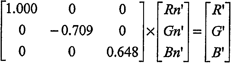
감마 보정 부호 값과 같이 비선형적으로 관련된 양을 이용하여 명암도를 근사할 경우 색 에러가 발생한다. 그러나, 선형적으로부터 벗어난 정도와 어느 정도 밀접하게 사용되었는지에 따라 시간과 제조단가 절약을 고려할 때 그 에러는 만족스러울 정도로 줄어든다. 예컨대, 도 3은 OLED에 관한 특성 곡선 부호 값의 응답으로 OLED의 비선형 명암도를 도시하고 있다. 그 곡선에는 외관상 그 상부에서 하부보다 상당히 선형적이 되는 굴곡부(52)가 있다. 명암도를 근사하기 위해 부호값을 사용하는 것은 아마도 좋지 않은 선택일 수 있지만, 도시된 굴곡부(52)를 사용하여 부호값에서 상수(도 3에 도시된 예에서 약 175)를 감하는 것은 보다 나은 근사치를 만든다. 도 2에 도시된 방법으로 제공된 신호(R,G,B)는 하기와 같이 계산된다. Color errors occur when the contrast is approximated using nonlinearly related quantities, such as gamma correction code values. However, depending on the degree of deviation from linearity and how closely it is used, the error is satisfactorily reduced when considering time and manufacturing cost savings. For example, FIG. 3 shows the nonlinear intensity of an OLED in response to characteristic curve sign values for the OLED. The curve has a

본 이동은 도 2에 도시된 방법이 하기 단계에 의해 계산된 후에 삭제된다. This movement is deleted after the method shown in Fig. 2 is calculated by the following steps.

본 근사치는 단순하게 룩업(lookup) 동작을 추가하여 대체하므로 공정 시간 또는 하드웨어 제조 단가를 절약할 수 있다. This approximation is simply replaced by the addition of a lookup operation, saving process time or hardware manufacturing costs.
본 발명을 삼색 입력를 사색 이상의 출력 신호로 변환하는데 이용하는 것은 도 2에 도시된 방법을 순차적으로 적용할 것을 필요로 한다. 이 방법을 각각 순차적으로 적용하여 추가 원색 중 하나에 대한 신호를 계산하고, 계산의 순서는 원색에 할당된 우선순위와 반대 순서로 결정된다. 예를 들어, 각각 (0.637,0.3592),(0.2690,0.6508) 및 (0.1441,0.1885)의 색도를 갖는 적색, 녹색 및 청색에 더하여 (0.3405,0.3530)의 색도를 갖는 연황색과 (0.2980,0.3105)의 색도를 갖는 연청색의 두 개의 추가 원색을 갖는 OLED 디스플레이 장치를 고려해 보자. 이 추가 원색은 각각 연황색과 연청색으로 불리울 것이다. Using the present invention to convert a tricolor input into an output signal of four or more colors requires the application of the method shown in FIG. Each of these methods is applied sequentially to calculate the signal for one of the additional primary colors, and the order of calculation is determined in the reverse order of the priority assigned to the primary colors. For example, light yellow and (0.2980,0.3105) having a chromaticity of (0.3405,0.3530) in addition to red, green and blue having a chromaticity of (0.637,0.3592), (0.2690,0.6508) and (0.1441,0.1885), respectively. Consider an OLED display device with two additional primary colors of light blue with a chromaticity of. These additional primary colors will be called light yellow and light blue, respectively.
추가 원색의 우선순위를 정할 경우에 시간에 따른 휘도 안정성과 전력 효율성 또는 발광기의 다른 특성을 고려할 수 있다. 이러한 경우에, 황색의 전력 효율성이 연청색보다 훨씬 높다면 계산의 순서는 연청색을 우선 진행하고 그 다음에 황색을 진행한다. 적색, 녹색, 청색 및 연청색의 명암도가 계산되었다면, 남아있는 세 신호를 네 신호로 변환하기 위해 하나의 신호를 따로 설정해두어야 한다. 따로 설정된 값을 선택하는 것은 임의이지만 F1함수에 의해 계산된 최소 소스인 신호를 선택하는 것이 최상이다. 만일 그 신호가 녹색의 명암도라면, 황색의 명암도는 적색, 청색 및 연청색의 명암도를 기반으로 하여 계산된다. 5가지 모두는 결과적으로 디스플레이에 적색, 녹색, 청색, 연청색 및 황색 명암도로 출력된다. 디스플레이 장치에 이들의 조합으로 3x5 형광체 매트릭스가 생성될 수 있다. 이 기술은 삼색 입력 신호에서 시작되는 많은 추가 원색에 대한 신호를 계산하는 것으로 용이하 게 확장될 수 있다. Prioritizing additional primary colors can take into account brightness stability and power efficiency over time or other characteristics of the light emitter. In this case, if the power efficiency of yellow is much higher than light blue, the order of calculation proceeds first to light blue and then to yellow. Once the contrast levels of red, green, blue and light blue have been calculated, one signal must be set aside to convert the remaining three signals into four signals. It is arbitrary to choose a set value, but it is best to choose a signal that is the minimum source calculated by the F1 function. If the signal is green and dark, yellow and yellow are calculated based on the red, blue and light blue contrasts. All five result in red, green, blue, light blue and yellow contrast on the display. Combinations of these may be generated in the display device in a 3x5 phosphor matrix. This technique can be easily extended by calculating the signal for many additional primary colors starting from the tricolor input signal.
도 2에 설명된 방법은 RGB에서 R'G'B'W로의 변환이 OLED 장치의 물리적인 제약과 조화를 이룰 수 있도록 최적화되도록 더 변경될 수 있다. 본 발명의 발명자에 의해 수행된 수학적 시뮬레이션은 OLED 디스플레이의 수명의 모델링을 보여주는데, 이 시뮬리에션에서 백색 OLED의 색도 좌표가 디스플레이 백광의 색도 좌표와 거의 같으면 RGB OLED와 크기가 동일한 백색 OLED의 수명은 RGB OLED의 수명보다 현저하게 감소할 수 있음을 알 수 있다. 예컨대, 디지털 카메라의 뒷면에서 사용되도록 설계된 전형적인 디스플레이에서 적색, 녹색 및 청색 OLED의 투영 수명은 이 조건하에서 백색 OLED의 투영 수명의 두 배 이상이다. 디스플레이 장치의 수명이 가장 짧은 수명을 가진 OLED에 의해 제한되므로 사원색을 생성하는데 사용되는 사색 OLED의 수명 간에 더 나은 균형을 제공하는 것이 중요하다. The method described in FIG. 2 can be further modified such that the conversion from RGB to R'G'B'W is optimized to match the physical constraints of the OLED device. Mathematical simulations performed by the inventors of the present invention show the modeling of the lifespan of an OLED display. In this simulation, if the chromaticity coordinates of a white OLED are approximately equal to the chromaticity coordinates of a display white light, the lifetime of a white OLED of the same size as an RGB OLED is It can be seen that the life of the RGB OLED can be significantly reduced. For example, in typical displays designed for use on the back of a digital camera, the projection life of red, green and blue OLEDs is more than twice the projection life of white OLEDs under these conditions. Since the lifetime of the display device is limited by the OLED with the shortest lifetime, it is important to provide a better balance between the lifetimes of the four-color OLEDs used to generate the temple colors.
OLED의 수명이 OLED를 구동하는데 사용되는 전류 밀도에 달려있다는 것,즉 높은 전류 밀도가 수명을 현저하게 단축한다는 것을 이 기술 분야에 주지되어 있다. 도 4는 전류 밀도의 함수로서 OLED 수명 곡선을 도시한다. 또한 디스플레이의 전류 밀도는 OLED를 구동하는데 사용되는 전류에 비례하며, 전류는 생성되는 휘도에 비례하는 것으로 주지되어 있다. 그러므로, OLED에 고 명암도를 사용하지 않는다면 OLED의 수명은 증가할 수 있다. It is well known in the art that the lifetime of an OLED depends on the current density used to drive the OLED, i.e., the high current density significantly shortens the lifetime. 4 shows the OLED lifetime curve as a function of current density. It is also known that the current density of the display is proportional to the current used to drive the OLED, and the current is proportional to the luminance produced. Therefore, the lifetime of the OLED can be increased if high contrast is not used in the OLED.
도 2에 도시된 알고리즘은 R,G,B 명암도를 통상적으로 감소시키고 W 채널의 명암도를 증가시킨다. 백색의 색도 좌표를 백색 OLED의 색도 좌표와 거의 같게 생성하려 하면 적색, 녹색 및 청색 OLEDs의 수명은 증가되지만 백색 OLED는 고 명암 도를 생성한다. W에 대한 고 명암도를 사용하지 않기 위해서, F2와 F3은 S가 낮을 때보다 S가 높을 때 더 작은 절대값을 생성하도록 F2와 F3은 비선형 함수로 정의될 수 있다. 이들 함수는 수학적으로 또는 룩업 테이블(a look-up table)로 설명될 수 있다. 바람직한 룩업 테이블은 F2에는 -S를 F3에는 S를 제공하지만 S값이 몇몇 임계치보다 높을 경우 각각 -S와 S의 비율을 개별적으로 제공한다. W의 최대 명암도는 S의 분수와 컷-오프 값을 적당하게 선택함으로써 색 정확도의 손실 없이 선택될 수 있다. 그 다음에 W의 최대 명암도는 의도하는 애플리케이션에 있어서 백색 OLED의 수명을 적색, 녹색 및 청색 OLED의 수명과 동일하게 맞추도록 선택될 수 있다. The algorithm shown in FIG. 2 typically reduces the R, G, B contrast and increases the contrast of the W channel. Attempting to produce white chromaticity coordinates approximately equal to the chromaticity coordinates of white OLEDs increases the lifetime of red, green, and blue OLEDs, while white OLEDs produce high contrast. To avoid using high contrast for W, F2 and F3 can be defined as nonlinear functions such that F2 and F3 produce smaller absolute values when S is higher than when S is low. These functions can be described mathematically or as a look-up table. The preferred lookup table provides -S for F2 and S for F3, but separately providing the ratio of -S and S, respectively, when the S value is above some threshold. The maximum intensity of W can be selected without loss of color accuracy by properly selecting the fraction and cut-off value of S. The maximum contrast of W can then be selected to match the lifetime of the white OLED to the lifetime of the red, green and blue OLEDs in the intended application.
백색 OLED의 색도 좌표가 디스플레이 백광의 색도 좌표에 가까울 경우 RGB 신호의 표준화 단계(24,46) 또한 필요하지 않을 수 있다. 또는, 백색 원색에는 RGB 명암도를 표준화(24)하고 디스플레이 백광에는 표준화(36)하지 않을 수도 있다. If the chromaticity coordinates of the white OLED are close to the chromaticity coordinates of the display white light, the normalization steps 24 and 46 of the RGB signal may also not be necessary. Alternatively, RGB contrast may be standardized 24 for the white primary and not 36 for display white light.
본 발명의 방법은 인입 데이터가 OLED 디스플레이 장치상의 OLED의 RGBW 패턴으로 공간적 리샘플링되도록 하는 이미지 공정 방법의 관점에서 구현될 수 있다. 이러한 방법에서, 상술된 방법을 사용하여 삼색 입력 신호는 네 개(또는 이상)의 신호로 전형적으로 변환된다. 그 다음에 리샘플링이 수행되어 네 개 또는 이상의 컬러 디스플레이 장치 내의 OLED에 적합한 명암도를 결정한다. 이 리샘플링 공정은 샘플링 면적, 샘플링 위치 및 의도된 각 OLED의 크기와 같은 관련된 디스플레이 특성을 고려할 수도 있다. The method of the present invention can be implemented in terms of an image processing method that allows incoming data to be spatially resampled into the RGBW pattern of the OLED on the OLED display device. In this method, the tricolor input signal is typically converted into four (or more) signals using the method described above. Resampling is then performed to determine the appropriate brightness for the OLEDs in the four or more color display devices. This resampling process may take into account related display characteristics such as sampling area, sampling location, and size of each intended OLED.
이 공정은 입력 데이터에 대한 의도된 RGB 디스플레이 형식을 결정하는 단계를 더 포함할 수도 있다. 이 단계에서 특별히 공간적으로 배열된 OLED를 지닌 디스플레이 장치에 대해서 이미지 데이터가 이미 샘플링되었다고 결정하면, 화소 내 동일한 공간 장소를 나타내는 삼색 입력 신호를 생성하는 예비 샘플링이 수행될 수 있다. 그 다음으로 삼색에서 사색으로 변환하여 디스플레이 장치상에 각 공간 장소에서의 사색 값을 결정한다. This process may further include determining an intended RGB display format for the input data. If it is determined at this stage that the image data has already been sampled for a display device with a specially arranged OLED, preliminary sampling may be performed to generate a tricolor input signal representing the same spatial location within the pixel. It then converts from three colors to four colors to determine the four color values at each spatial location on the display device.
도 5에 도시된 공정은 삼색 신호의 변환과 리샘플링에 사용될 수 있다. 이 공정은 선형 명암도를 갖는 삼색 입력 신호를 수신한다(60). 공간적으로 샘플링된 입력 신호의 샘플 형식이 판정된다(62). 샘플 형식이 판정되면, 삼색 입력 신호가 상이한 공간 장소를 갖는 OLED를 위해 제공될 것인지 판정한다(64). 만일 데이터가 상이한 공간 장소에 있는 발광 소자를 위한 것이라면, 데이터가 각 샘플링 장소에서 삼색 정보를 지니도록 리샘플링하는(66) 선택적인 단계가 수행되고, 그 결과로 삼색 입력 신호에 표시된 각 공간 장소에서의 컬러 값, 최후의 디스플레이 상의 각 공간 장소에서의 컬러 값, 기타 다른 공간 장소에서 컬러 값이 생성될 수 있다. The process shown in FIG. 5 can be used for the conversion and resampling of tricolor signals. This process receives a tricolor input signal with linear contrast (60). The sample format of the spatially sampled input signal is determined (62). Once the sample format is determined, it is determined 64 whether the tricolor input signal will be provided for an OLED with a different spatial location. If the data is for a light emitting element at a different spatial location, an
그 다음에 삼색 신호는 도 2에 도시되고 이미 논의된 방법을 사용하여 네 개 또는 이상의 색 신호를 구성하도록 변환된다(68). 이후에, 만일 이 리샘플링이 단계(66)에서 완료되지 않았다면 네 개 또는 이상의 출력 신호는 네 개 또는 이상의 컬러 디스플레이 장치의 공간 패턴으로 리샘플링된다(70). 이러한 기본적인 단계는 삼색에서 사색 이상의 공간 보간 공정에 적용될 수 있지만, 입력 신호를 판정하 는 단계와 데이터 리샘플링하는 단계는 여러 가지 복잡한 단계를 포함하는 다양한 방법으로 달성될 수 있다. 이들 각각의 단계는 더욱 정교해질 것이다. The tricolor signal is then transformed 68 to construct four or more color signals using the method shown in FIG. 2 and already discussed. Thereafter, if this resampling has not been completed in
입력 신호 판정Input signal judgment
삼색 입력 신호를 해당하는 원색과 하나의 추가 원색으로 정의되는 영역으로 적합하게 변환하기 위해서는 공간적으로 겹쳐진 입력 신호(즉, 각 공간 장소에서 삼색 입력 신호를 제공하는 신호)가 필요하다. 그러나, 종래 기술에 삼색 신호의 공간 보간법이 주지되어 있으므로, 입력 신호는 이미 발광 소자가 특별히 공간적으로 배열된 디스플레이 장치를 위해 샘플링되었을 수 있다. 예를 들어, 인입 신호는 도 6a에 도시된 줄무늬 패턴으로 배열된 적색(84), 녹색(86) 및 청색(88) OLED가 공통 배열을 구성하는 화소(82)를 갖는 디스플레이 장치(80)용으로 공간적으로 샘플링되었을 수 있다. 즉, MS 윈도우 2000 등의 컴퓨터 운영 시스템에서 전형적인 제공 절차는 줄무늬 패턴을 가지는 디스플레이 장치상에 정보를 디스플레이할 의도로 정보를 제공할 수 있다. In order to properly convert a tricolor input signal into a region defined by a corresponding primary color and one additional primary color, a spatially overlapping input signal (ie, a signal providing a tricolor input signal in each spatial place) is required. However, since spatial interpolation of tricolor signals is well known in the prior art, the input signal may already have been sampled for a display device in which the light emitting elements are specifically spatially arranged. For example, the incoming signal is for
공간적으로 샘플링된 입력 신호의 형식을 판정하기 위해서 메타데이터 플래그 또는 신호 분석을 통해 의도된 데이터 형식과의 통신을 포함하는 많은 수단이 이용될 수 있다. 메타데이터를 사용하여 판정하기 위해서는, 삼색 입력 신호에는 디스플레이 장치에 있는 발광 소자들의 의도된 배열을 나타내는 하나 이상의 데이터 필드가 제공될 수 있다. Many means can be used to determine the format of a spatially sampled input signal, including communication with the intended data format via metadata flags or signal analysis. To determine using metadata, the tricolor input signal may be provided with one or more data fields representing the intended arrangement of light emitting elements in the display device.
또한, 인입 신호는 데이터 내 임의의 공간 오프셋을 판정하기 위해 분석될 수 있다 . 이러한 분석을 수행하기 위해서는, 삼색 입력 신호가 리샘플링되었는지를 나타내는 인입 신호의 특성을 판정하는 것이 중요하다. 이 분석을 수행하는 하나의 방법은 도 7에 도시된다. 이 방법은 리샘플링 없이 색 입력 신호, 도 6a에 도시된 바대로 리샘플링되어 줄무늬 패턴으로 제공되는 색 입력 신호 및 도 6b에 도시된 바대로 리 샘플링되어 델타 패턴으로 제공되는 색 입력 신호의 상이한 세 가지 색 입력 신호를 자동으로 구별하게 한다. 이들 공간 배열은 디스플레이 산업에서 공통으로 이용되는 배열이므로, 이들 패턴은 본 예에 포함되었다. 그러나, 본 발명의 방법이 색 입력 신호가 다른 패턴으로 리샘플링되었는지를 판정하도록 확장될 수 있음은 이 분야의 통상의 지식을 가진 자에게 자명할 것이다. In addition, the incoming signal can be analyzed to determine any spatial offset in the data. To perform this analysis, it is important to determine the characteristics of the incoming signal that indicates whether the tricolor input signal has been resampled. One method of performing this analysis is shown in FIG. This method uses three different colors of a color input signal without resampling, a color input signal that is resampled as shown in FIG. 6A and provided in a striped pattern, and a color input signal that is resampled and shown in a delta pattern as shown in FIG. 6B. Automatically distinguish input signals. Since these spatial arrangements are arrangements commonly used in the display industry, these patterns are included in this example. However, it will be apparent to one of ordinary skill in the art that the method of the present invention can be extended to determine if a color input signal has been resampled in another pattern.
도 7에 도시된바 대로, 에지 개선은 각 삼색 입력 신호에 대해서 수행된다(90). 도 6a에 도시된 줄무늬 패턴처럼, OLED 배열은 수평 방향으로 서로 떨어진 OLED로 구성되어 있으므로, 수평 에지 개선 절차는 이미지 신호에 적용될 수 있다. 각 수평 위치(i)에서의 값과 수직 위치(j)에서의 값을 다음의 식으로 계산함으로써 이러한 디지털 에지 개선 알고리즘을 적용할 수 있다. As shown in FIG. 7, edge enhancement is performed for each tricolor input signal (90). As the stripe pattern shown in Fig. 6A, the OLED array is composed of OLEDs spaced from each other in the horizontal direction, so the horizontal edge enhancement procedure can be applied to the image signal. This digital edge enhancement algorithm can be applied by calculating the value at each horizontal position (i) and the value at the vertical position (j) by the following equation.
![]()
![]()
여기서, ![]()
![]()
![]()
![]()
![]()
![]()
그 다음에 세 개의 에지가 개선된 색 입력 신호에서 에지 화소가 판정된다 (92). 에지 화소를 결정하는 공통 기술은 개선 값에 임계치를 적용하는 것이다. 적당한 임계치보다 높은값을 가지는 위치가 에지 화소로서 고려된 임계치는 세 개의 에지가 개선된 색 신호에 있어서 동일하거나 서로 다를 수 있다. An edge pixel is then determined 92 in the color input signal where the three edges are enhanced. A common technique for determining edge pixels is to apply a threshold to an improvement value. Thresholds considered as edge pixels whose position is higher than the appropriate threshold may be the same or different for the three edge enhanced color signal.
그 다음에 모든 삼색 채널에서 신호를 가지는 하나 이상의 에지 위치가 정해진다(94). 이들 에지 위치는 그 값이 화소의 크기에 의해 결정되는 샘플링 윈도우 space 내에서 생성되는 임계치보다 큰 모든 값을 갖는 개선 화소를 포함하는 공간 위치를 판정함으로써 찾을 수 있을 것이다. One or more edge positions with signals in all three color channels are then determined 94. These edge positions may be found by determining a spatial position including an enhancement pixel whose value is greater than a threshold generated within a sampling window space determined by the size of the pixel.
그 다음에 에지 특성의 위치가 판정된다(96). 예를 들어, 적당한 에지 특성은 각 에지 높이의 절반인 공간 위치가 될 수 있다. 에지 외형의 절반 높이를 계산하기 위해 제 2차 다항식 또는 S자 모양 함수 등을 에지 화소 위치의 3 내지 5개의 화소 내의 원래의 데이터에 적용할 수 있다. 그 다음에 함수의 한점, 즉, 최대 크기의 절반이 판정되고 이값의 공간 위치는 에지 특성의 위치로써 판정된다. 이 단계는 각 삼색 입력 신호 내 에지에 대해서 독립적으로 완료된다. The position of the edge characteristic is then determined 96. For example, a suitable edge characteristic can be a spatial location that is half of each edge height. A second order polynomial or an S-shape function or the like may be applied to the original data within three to five pixels of the edge pixel position to calculate the half height of the edge contour. Then one point of the function, ie half of the maximum magnitude, is determined and the spatial position of this value is determined as the position of the edge characteristic. This step is completed independently for the edge in each tricolor input signal.
삼색 입력 신호에 대한 에지 특성의 공간 위치는 비교될 수 있고(98) 각 에지 특성의 정렬의 정도가 분석된다. 그러나, 이들 위치가 정확하지 않으므로 화소 에지의 공간 위치에 대한 상대적인 공간 위치가 각 색 신호 내 다수의 에지에 관해 판정되고, 각 색 입력 신호 내의 식별된 모든 에지 위치에 대해서는 평균화 된다(100).The spatial position of the edge characteristic relative to the tricolor input signal can be compared 98 and the degree of alignment of each edge characteristic is analyzed. However, since these positions are not accurate, the relative spatial position relative to the spatial position of the pixel edge is determined for a number of edges in each color signal, and averaged (100) for all identified edge positions in each color input signal.
그 다음에 각 색상에 대한 에지 특성의 평균 상대 위치는 다른 색상에 대한 에지 특성의 평균 상대 위치와 비교된다(102). 만일 삼색에 관한 이들 에지 특성 중 적어도 2개가 OLED의 폭보다 더 많이 벗어나면, 이전에 공간 리샘플링 단계가 수행되었다는 것을 의미한다. 이 비교를 통해서, 공간 리샘플링이 적용되었는지를 판정한다(104). 그 다음에 만일 세 개의 에지 특성 모두가 정렬되지 않으면, 도 6a에 도시된 줄무늬 패턴처럼, 신호는 하나 차원에 그들의 에너지 전부를 지닌 발광 소자의 패턴으로 보간된다. 그 다음에 만일 하나의 열에 두 가지 색상의 에지 특성이 이웃 열 위에 하나 이상의 색상의 에지 특성과 동일한 공간 위치에서 발생한다면, 도 6b에 도시된 델타 패턴처럼, 신호는 두 열을 교차하여 전개되는 발광 소자의 패턴으로 보간된다. 이 비교를 통해서, 디스플레이의 발광 소자의 가정된 공간 배열이 판정된다(106).The average relative position of the edge characteristic for each color is then compared 102 with the average relative position of the edge characteristic for the other colors. If at least two of these edge characteristics for the tricolor deviate more than the width of the OLED, it means that the spatial resampling step was performed previously. Through this comparison, it is determined 104 whether spatial resampling has been applied. Then, if all three edge characteristics are not aligned, the signal is interpolated into a pattern of light emitting elements with all of their energy in one dimension, like the striped pattern shown in FIG. 6A. Then, if two colored edge characteristics in one column occur at the same spatial location as one or more colored edge characteristics over a neighboring column, then the signal evolves across the two columns, as shown in the delta pattern shown in FIG. 6B. Interpolated with the pattern of the device. Through this comparison, the assumed spatial arrangement of the light emitting elements of the display is determined 106.
리샘플링Resampling
리샘플링은 도 6a와 도 6b에 도시된 바대로, 종래 기술의 줄무늬 패턴 또는 델타 패턴 상에 디스플레이하기 위한 형식에서, 모든 공간 배열에서 값을 나타내는 색 신호를 가지는 형식으로 데이터를 리샘플링하도록 수행되거나 모든 공간 배열에서 색 신호를 가지는 형식에서 도 8a에 도시된 줄무늬 패턴 또는 도 8b에 도시된 쿼드 패턴과 같이 백색 서브 픽셀을 포함하는 패턴으로 데이터를 리샘플링하는데 사용될 수 있다. 이들 각 도면에서 보이듯이, 디스플레이 장치(110)는 적색 OLED(114), 녹색 OLED(116), 청색 OLED(118) 및 백색 OLED(120)를 지닌 화소(112)로 구성된다. Resampling is performed to resample data in a format having a color signal representing values in all spatial arrangements, or in all spatial, in a format for display on a striped pattern or delta pattern of the prior art, as shown in FIGS. 6A and 6B. In a format having a color signal in an arrangement, the data may be used to resample data into a pattern including white subpixels, such as a stripe pattern shown in FIG. 8A or a quad pattern shown in FIG. 8B. As shown in each of these figures,
다양한 리샘플링 기술은 이 기술 분야에 공지되어 있고 상술된 바와 같이 미 국 특허 출원 제2003/0034992A1호를 포함하는 다른 특허출원들과 Klompenhouwer 등의 "Subpixel Image Scaling for Color Matrix Displays", SID 02 Digest, pp.176-179에 기재되어 있다. 이들 기술은 통상적으로 동일한 기본 단계를 포함한다. 리샘플링을 수행하기 위해서, 단일 컬러 신호(예:적색, 녹색, 청색, 또는 백색)가 선택된다(130). 입력 신호의 샘플링 그리드(즉, 각 샘플링의 위치)가 판정된다(132). 그 다음에 원하는 샘플링 그리드(134)가 판정된다. 화소 내 공간 위치에 해당하는 샘플 포인트는 원하는 샘플링 그리드 안에서 선택된다(136). 만일 이 공간 위치에서 입력 신호 내에 샘플이 존재하지 않으면, 색 신호 안에서 인접한 입력 신호(즉, 공정에 리샘플링이 적용되는 때에 따라 삼색 입력 신호 또는 사색 입력 신호 중 하나) 값들은 하나 또는 두 개의 차원 내에 위치가 지정된다(138). 그 다음에 인접한 입력 신호 값에 의해 표현되는 공간 위치와 관련된 가중 비율의 한 세트가 계산된다(140). 이들 비율은 많은 수단에 의해 계산될 수 있는데, 이 수단은 각 공간 차원 내의 입력 신호에서 원하는 샘플 위치에서 인접한 샘플까지의 거리를 판정하고, 이 거리들을 가산하고, 각 거리를 선택된 샘플 포인트에서 각 차원에서 인접한 샘플의 위치까지의 거리의 합으로 나누는 방법을 포함한다. 그 다음에 인접한 입력 신호 값은 각각 개별 가중치가 곱해져서(142) 가중 입력 신호 값이 생성된다. 그 다음에 결과값들은 함께 더해져서(144) 원하는 샘플링 그리드 내의 선택된 위치에서 리샘플링된 데이터를 얻는다. 이 동일한 공정은 원하는 샘플링 그리드 내에서 각 그리드 위치에 대해 반복한(146) 후 각 색 신호에 대해 반복한다. Various resampling techniques are known in the art and include other patent applications, including US Patent Application No. 2003 / 0034992A1, as described above, and "Subpixel Image Scaling for Color Matrix Displays" by Klompenhouwer et al., SID 02 Digest, pp. 176-179. These techniques typically include the same basic steps. To perform the resampling, a single color signal (eg, red, green, blue, or white) is selected 130. A sampling grid of the input signal (ie, the location of each sampling) is determined 132. The desired
도 5에 도시된 바대로, 공간 리샘플링과 색 변환을 수행함으로써 결과 신호 는 삼색 신호에서 사색 이상의 컬러 신호로 변환될 뿐만 아니라, 하나의 가정 된 공간 샘플링을 가지는 삼색 신호에서 원하는 공간 샘플링을 가지는 삼색 이상의 신호로 변환된다. As shown in Fig. 5, by performing spatial resampling and color conversion, the resulting signal is not only converted from the tricolor signal to the four or more color signals, but also three or more colors having the desired spatial sampling from the tricolor signal having one assumed spatial sampling. Is converted into a signal.
이 방법은 특정 집적 회로적용 제품(asic), 프로그램 가능한 논리 장치, 디스플레이 드라이버 또는 소프트웨어 생산품으로 구현될 수 있다. 이 생산품 각각은 프로그램가능한 파라미터를 저장함으로써 조정될 함수 F1, F2 및 F3함수를 형성하게 할 수 있다. 이들 파라미터는 제조 환경 내에서 또는 이 파라미터에 액세스를 허용하는 소프트웨어 생산품을 통해 조정될 수 있다. This method can be implemented with specific integrated circuit applications, programmable logic devices, display drivers or software products. Each of these products can be made to form functions F1, F2 and F3 to be adjusted by storing programmable parameters. These parameters can be adjusted within the manufacturing environment or through a software product that allows access to these parameters.
종래 기술은 OLED 디스플레이 장치 내 OLED 물질의 노화 또는 부식을 보정하는 방법을 제공한다. 이들 방법은 각 화소 내에서 각 원색 또는 각 원색의 휘도 추정을 제공하여 OLED 물질의 부식을 측정하고 예측하는 수단을 제공한다. 이 정보가 이용가능하면, 이 정보는 디스플레이의 비교 휘도 계산에 입력으로 사용될 수 있다. 이와 달리, 노화를 판정하는 방법을 갖는 디스플레이 장치는 장치 내에서 부식이 최대로 진행중인 원색에 대한 의존도가 감소하도록 F1, F2 및 F3 함수를 조정하는 것이 바람직하다. 적색, 녹색, 청색 및 백색 신호를 갖는 디스플레이 장치에서, 임의의 또는 F1, F2 및 F3 함수 모두를 조정함으로써 적색, 녹색 및 청색 쪽으로 또는 백색 쪽으로 휘도 출력을 시프트시킬 수 있으며, OLEDs 이들 그룹 중 하나의 휘도 출력이 낮아지면 원하는 색상을 생성하는데 사용되는 OLED의 부식은 느리게 진행한다. The prior art provides a method of correcting aging or corrosion of OLED materials in OLED display devices. These methods provide a means of measuring and predicting corrosion of the OLED material by providing a luminance estimate of each primary color or each primary color within each pixel. If this information is available, this information can be used as input to the comparative luminance calculation of the display. In contrast, display devices having a method of determining aging preferably adjust the F1, F2 and F3 functions to reduce the dependence on the primary color where corrosion is maximizing in the device. In display devices with red, green, blue and white signals, the luminance output can be shifted towards the red, green and blue or towards white by adjusting any or all of the F1, F2 and F3 functions, and OLEDs can be At lower luminance outputs, the corrosion of the OLEDs used to produce the desired color is slow.
본 발명은 바람직한 특정 실시예에 구체적인 참조로서 상세하게 설명되었지 만, 본 발명의 사상과 범위 내에서 변경 및 수정될 수 있다. Although the invention has been described in detail with specific reference to certain preferred embodiments, it may be changed and modified within the spirit and scope of the invention.
본 발명은 디스플레이 시스템에서 추가 OLED가 디스플레이의 백광에 해당하지 않는 경우 색 정확도를 보존하는 변환을 제공한다는 장점이 있다. 추가 적으로, 본 발명의 일 측면에 따르면, 이 변환으로 OLED 디스플레이 장치의 수명을 보존하도록 맵핑을 최적화할 수 있다. 또한 변환은 데이터를 OLED의 원하는 공간 배열로 공간적으로 재구성하는 방법을 제공할 수 있다.The invention has the advantage of providing a conversion in the display system that preserves color accuracy when the additional OLED does not correspond to the white light of the display. In addition, according to one aspect of the present invention, this conversion can optimize the mapping to preserve the lifetime of the OLED display device. Transformation can also provide a way to spatially reconstruct data into the desired spatial arrangement of the OLED.
Claims (37)
Applications Claiming Priority (2)
| Application Number | Priority Date | Filing Date | Title |
|---|---|---|---|
| US10/607,374 US6897876B2 (en) | 2003-06-26 | 2003-06-26 | Method for transforming three color input signals to four or more output signals for a color display |
| US10/607,374 | 2003-06-26 |
Publications (2)
| Publication Number | Publication Date |
|---|---|
| KR20060024001A KR20060024001A (en) | 2006-03-15 |
| KR101041882B1 true KR101041882B1 (en) | 2011-06-16 |
Family
ID=33540249
Family Applications (1)
| Application Number | Title | Priority Date | Filing Date |
|---|---|---|---|
| KR1020057024988A KR101041882B1 (en) | 2003-06-26 | 2004-06-16 | Transforming three color input signals to more color signals |
Country Status (8)
| Country | Link |
|---|---|
| US (1) | US6897876B2 (en) |
| EP (1) | EP1636788B1 (en) |
| JP (1) | JP4829110B2 (en) |
| KR (1) | KR101041882B1 (en) |
| CN (1) | CN100444245C (en) |
| DE (1) | DE602004020471D1 (en) |
| TW (1) | TWI367476B (en) |
| WO (1) | WO2005004104A2 (en) |
Cited By (2)
| Publication number | Priority date | Publication date | Assignee | Title |
|---|---|---|---|---|
| KR20130136244A (en) * | 2012-06-04 | 2013-12-12 | 삼성전자주식회사 | Method of displaying image, computer readable storage medium of recording the method, and signal processing apparatus |
| WO2018008826A1 (en) * | 2016-07-07 | 2018-01-11 | 삼성전자 주식회사 | Electronic device and data processing method thereof |
Families Citing this family (151)
| Publication number | Priority date | Publication date | Assignee | Title |
|---|---|---|---|---|
| US8022969B2 (en) * | 2001-05-09 | 2011-09-20 | Samsung Electronics Co., Ltd. | Rotatable display with sub-pixel rendering |
| US7221381B2 (en) * | 2001-05-09 | 2007-05-22 | Clairvoyante, Inc | Methods and systems for sub-pixel rendering with gamma adjustment |
| US7123277B2 (en) | 2001-05-09 | 2006-10-17 | Clairvoyante, Inc. | Conversion of a sub-pixel format data to another sub-pixel data format |
| US7307646B2 (en) * | 2001-05-09 | 2007-12-11 | Clairvoyante, Inc | Color display pixel arrangements and addressing means |
| US7184066B2 (en) * | 2001-05-09 | 2007-02-27 | Clairvoyante, Inc | Methods and systems for sub-pixel rendering with adaptive filtering |
| US7714824B2 (en) | 2001-06-11 | 2010-05-11 | Genoa Color Technologies Ltd. | Multi-primary display with spectrally adapted back-illumination |
| WO2002101644A2 (en) * | 2001-06-11 | 2002-12-19 | Genoa Technologies Ltd. | Device, system and method for color display |
| US8289266B2 (en) * | 2001-06-11 | 2012-10-16 | Genoa Color Technologies Ltd. | Method, device and system for multi-color sequential LCD panel |
| WO2003053068A2 (en) | 2001-12-14 | 2003-06-26 | Clairvoyante Laboratories, Inc. | Improvements to color flat panel display sub-pixel arrangements and layouts with reduced visibility of a blue luminance well |
| US20030117423A1 (en) * | 2001-12-14 | 2003-06-26 | Brown Elliott Candice Hellen | Color flat panel display sub-pixel arrangements and layouts with reduced blue luminance well visibility |
| US7755652B2 (en) * | 2002-01-07 | 2010-07-13 | Samsung Electronics Co., Ltd. | Color flat panel display sub-pixel rendering and driver configuration for sub-pixel arrangements with split sub-pixels |
| US7417648B2 (en) | 2002-01-07 | 2008-08-26 | Samsung Electronics Co. Ltd., | Color flat panel display sub-pixel arrangements and layouts for sub-pixel rendering with split blue sub-pixels |
| US20040051724A1 (en) * | 2002-09-13 | 2004-03-18 | Elliott Candice Hellen Brown | Four color arrangements of emitters for subpixel rendering |
| US7492379B2 (en) * | 2002-01-07 | 2009-02-17 | Samsung Electronics Co., Ltd. | Color flat panel display sub-pixel arrangements and layouts for sub-pixel rendering with increased modulation transfer function response |
| US7583279B2 (en) * | 2004-04-09 | 2009-09-01 | Samsung Electronics Co., Ltd. | Subpixel layouts and arrangements for high brightness displays |
| AU2003219505A1 (en) * | 2002-04-11 | 2003-10-27 | Moshe Ben-Chorin | Color display devices and methods with enhanced attributes |
| US7365722B2 (en) * | 2002-09-11 | 2008-04-29 | Samsung Electronics Co., Ltd. | Four color liquid crystal display and driving device and method thereof |
| US7046256B2 (en) * | 2003-01-22 | 2006-05-16 | Clairvoyante, Inc | System and methods of subpixel rendering implemented on display panels |
| EP1590784B1 (en) | 2003-01-28 | 2008-06-04 | Genoa Color Technologies Ltd. | Subpixel arrangement for displays with more than three primary colors |
| US20040196302A1 (en) * | 2003-03-04 | 2004-10-07 | Im Moon Hwan | Systems and methods for temporal subpixel rendering of image data |
| KR100929673B1 (en) * | 2003-03-25 | 2009-12-03 | 삼성전자주식회사 | Display device driving device and driving method thereof |
| US7352374B2 (en) * | 2003-04-07 | 2008-04-01 | Clairvoyante, Inc | Image data set with embedded pre-subpixel rendered image |
| KR100943273B1 (en) * | 2003-05-07 | 2010-02-23 | 삼성전자주식회사 | Method and apparatus for converting a 4-color, and organic electro-luminescent display device and using the same |
| US7230584B2 (en) * | 2003-05-20 | 2007-06-12 | Clairvoyante, Inc | Projector systems with reduced flicker |
| US7268748B2 (en) * | 2003-05-20 | 2007-09-11 | Clairvoyante, Inc | Subpixel rendering for cathode ray tube devices |
| US20040233308A1 (en) * | 2003-05-20 | 2004-11-25 | Elliott Candice Hellen Brown | Image capture device and camera |
| US7209105B2 (en) * | 2003-06-06 | 2007-04-24 | Clairvoyante, Inc | System and method for compensating for visual effects upon panels having fixed pattern noise with reduced quantization error |
| US7397455B2 (en) * | 2003-06-06 | 2008-07-08 | Samsung Electronics Co., Ltd. | Liquid crystal display backplane layouts and addressing for non-standard subpixel arrangements |
| US20040246280A1 (en) * | 2003-06-06 | 2004-12-09 | Credelle Thomas Lloyd | Image degradation correction in novel liquid crystal displays |
| US7187353B2 (en) * | 2003-06-06 | 2007-03-06 | Clairvoyante, Inc | Dot inversion on novel display panel layouts with extra drivers |
| US8035599B2 (en) | 2003-06-06 | 2011-10-11 | Samsung Electronics Co., Ltd. | Display panel having crossover connections effecting dot inversion |
| US7598961B2 (en) * | 2003-10-21 | 2009-10-06 | Samsung Electronics Co., Ltd. | method and apparatus for converting from a source color space to a target color space |
| US7728846B2 (en) * | 2003-10-21 | 2010-06-01 | Samsung Electronics Co., Ltd. | Method and apparatus for converting from source color space to RGBW target color space |
| US7084923B2 (en) * | 2003-10-28 | 2006-08-01 | Clairvoyante, Inc | Display system having improved multiple modes for displaying image data from multiple input source formats |
| US7525526B2 (en) * | 2003-10-28 | 2009-04-28 | Samsung Electronics Co., Ltd. | System and method for performing image reconstruction and subpixel rendering to effect scaling for multi-mode display |
| US7929752B2 (en) * | 2003-10-31 | 2011-04-19 | Nano Picture Co., Ltd. | Method for generating structured-light pattern |
| KR101012790B1 (en) * | 2003-12-30 | 2011-02-08 | 삼성전자주식회사 | Apparatus and method of converting image signal for four color display device, and display device comprising the same |
| KR20050072505A (en) * | 2004-01-06 | 2005-07-12 | 삼성전자주식회사 | Apparatus and method of converting image signal for four color display device |
| WO2005076257A2 (en) * | 2004-02-09 | 2005-08-18 | Genoa Color Technologies Ltd. | Method device, and system of displaying a more-than-three primary color image |
| US7301543B2 (en) * | 2004-04-09 | 2007-11-27 | Clairvoyante, Inc. | Systems and methods for selecting a white point for image displays |
| US7248268B2 (en) * | 2004-04-09 | 2007-07-24 | Clairvoyante, Inc | Subpixel rendering filters for high brightness subpixel layouts |
| US7825921B2 (en) * | 2004-04-09 | 2010-11-02 | Samsung Electronics Co., Ltd. | System and method for improving sub-pixel rendering of image data in non-striped display systems |
| US7590299B2 (en) * | 2004-06-10 | 2009-09-15 | Samsung Electronics Co., Ltd. | Increasing gamma accuracy in quantized systems |
| JP2006003475A (en) * | 2004-06-15 | 2006-01-05 | Eastman Kodak Co | Oled display device |
| US20050285828A1 (en) * | 2004-06-25 | 2005-12-29 | Sanyo Electric Co., Ltd. | Signal processing circuit and method for self-luminous type display |
| KR101328547B1 (en) * | 2004-11-01 | 2013-11-13 | 테크니컬러, 인크. | Method and system for mastering and distributing enhanced color space content |
| JP4752294B2 (en) * | 2005-03-04 | 2011-08-17 | パナソニック株式会社 | Display device |
| KR101297734B1 (en) | 2005-04-04 | 2013-08-20 | 삼성디스플레이 주식회사 | Pre-subpixel rendered image processing in display systems |
| CN1882103B (en) * | 2005-04-04 | 2010-06-23 | 三星电子株式会社 | Systems and methods for implementing improved gamut mapping algorithms |
| WO2006108083A2 (en) * | 2005-04-04 | 2006-10-12 | Clairvoyante Inc | Systems and methods for implementing low cost gamut mapping algorithms |
| EP1882234B1 (en) * | 2005-05-20 | 2019-01-02 | Samsung Display Co., Ltd. | Multiprimary color subpixel rendering with metameric filtering |
| US7705855B2 (en) | 2005-06-15 | 2010-04-27 | Samsung Electronics Co., Ltd. | Bichromatic display |
| US7433514B2 (en) * | 2005-07-13 | 2008-10-07 | Canon Kabushiki Kaisha | Tone mapping of high dynamic range images |
| US7636076B2 (en) * | 2005-09-22 | 2009-12-22 | Au Optronics Corporation | Four-color transflective color liquid crystal display |
| US20070076276A1 (en) * | 2005-10-05 | 2007-04-05 | Dell Products L.P. | Color optimization of displayed image for PC projectors |
| WO2007060672A2 (en) * | 2005-11-28 | 2007-05-31 | Genoa Color Technologies Ltd. | Sub-pixel rendering of a multiprimary image |
| US7742205B2 (en) * | 2005-12-16 | 2010-06-22 | Vp Assets Limited Registered In British Virgin Islands | Perceptual color matching method between two different polychromatic displays |
| CN101346984B (en) | 2005-12-21 | 2012-12-26 | 汤姆森特许公司 | Method for displaying colorful image and color display device for image |
| US20070159492A1 (en) * | 2006-01-11 | 2007-07-12 | Wintek Corporation | Image processing method and pixel arrangement used in the same |
| US7791621B2 (en) * | 2006-04-18 | 2010-09-07 | Toppoly Optoelectronics Corp. | Systems and methods for providing driving voltages to RGBW display panels |
| US20070257945A1 (en) * | 2006-05-08 | 2007-11-08 | Eastman Kodak Company | Color EL display system with improved resolution |
| US20070257866A1 (en) * | 2006-05-08 | 2007-11-08 | Eastman Kodak Company | Method and apparatus for defect correction in a display |
| US7965305B2 (en) * | 2006-05-08 | 2011-06-21 | Global Oled Technology Llc | Color display system with improved apparent resolution |
| US20070257943A1 (en) * | 2006-05-08 | 2007-11-08 | Eastman Kodak Company | Method for rendering color EL display and display device with improved resolution |
| US7969428B2 (en) * | 2006-05-08 | 2011-06-28 | Global Oled Technology Llc | Color display system with improved apparent resolution |
| US7592996B2 (en) * | 2006-06-02 | 2009-09-22 | Samsung Electronics Co., Ltd. | Multiprimary color display with dynamic gamut mapping |
| WO2007143340A2 (en) * | 2006-06-02 | 2007-12-13 | Clairvoyante, Inc | High dynamic contrast display system having multiple segmented backlight |
| CN101460917B (en) * | 2006-06-02 | 2011-09-28 | 三星电子株式会社 | High dynamic contrast display system having multiple segmented backlight |
| US20070291510A1 (en) * | 2006-06-15 | 2007-12-20 | Wintek Corporation | Backlight module and light guide plate thereof |
| KR20070121163A (en) * | 2006-06-21 | 2007-12-27 | 삼성전자주식회사 | Multi-color display device and driving method thereof |
| KR20080009497A (en) * | 2006-07-24 | 2008-01-29 | 삼성전자주식회사 | Multi-color display device and driving method thereof |
| US7876341B2 (en) * | 2006-08-28 | 2011-01-25 | Samsung Electronics Co., Ltd. | Subpixel layouts for high brightness displays and systems |
| US8018476B2 (en) | 2006-08-28 | 2011-09-13 | Samsung Electronics Co., Ltd. | Subpixel layouts for high brightness displays and systems |
| JP4363430B2 (en) * | 2006-08-31 | 2009-11-11 | ソニー株式会社 | Color gamut conversion apparatus and color gamut conversion method |
| JP5431941B2 (en) * | 2006-09-20 | 2014-03-05 | コーニンクレッカ フィリップス エヌ ヴェ | Dynamic color gamut control |
| US8259127B2 (en) | 2006-09-30 | 2012-09-04 | Samsung Electronics Co., Ltd. | Systems and methods for reducing desaturation of images rendered on high brightness displays |
| CN101529496B (en) * | 2006-10-19 | 2012-01-11 | 皇家飞利浦电子股份有限公司 | Color mapping method, system and display device |
| US8269799B2 (en) * | 2006-10-25 | 2012-09-18 | Sanyo Electric Co., Ltd. | Image signal processor and image display device |
| US8134647B2 (en) * | 2006-11-09 | 2012-03-13 | Wintek Corporation | Image processing method and apparatus |
| TW200901815A (en) * | 2006-12-20 | 2009-01-01 | Koninkl Philips Electronics Nv | Lighting device with multiple primary colors |
| US7478922B2 (en) * | 2007-03-14 | 2009-01-20 | Renaissance Lighting, Inc. | Set-point validation for color/intensity settings of light fixtures |
| BRPI0721520B1 (en) * | 2007-04-03 | 2020-03-31 | Interdigital Madison Patent Holdings | METHODS AND SYSTEMS FOR COLOR CORRECTION OF SCREENS WITH DIFFERENT RANGE OF COLORS |
| US20080252797A1 (en) * | 2007-04-13 | 2008-10-16 | Hamer John W | Method for input-signal transformation for rgbw displays with variable w color |
| KR101329125B1 (en) * | 2007-08-13 | 2013-11-14 | 삼성전자주식회사 | Rgb to rgbw color decomposition method and system |
| US8094933B2 (en) * | 2007-12-13 | 2012-01-10 | Global Oled Technology Llc | Method for converting an input color signal |
| TWI385638B (en) * | 2007-12-21 | 2013-02-11 | Wintek Corp | Method for processing image, method and device for converting data of image |
| JP4683343B2 (en) * | 2007-12-27 | 2011-05-18 | 株式会社 日立ディスプレイズ | Color signal generator |
| KR101373501B1 (en) * | 2007-12-29 | 2014-03-13 | 엘지디스플레이 주식회사 | Method for driving liquid crystal display device |
| KR101397398B1 (en) * | 2008-01-14 | 2014-05-22 | 삼성전자주식회사 | System and method for converting rgb-to-rgbw according to gamut of rgbw output display |
| KR101480001B1 (en) * | 2008-02-26 | 2015-01-09 | 삼성디스플레이 주식회사 | Organic light emminting display device and processing method image signals thereof |
| JP2010020241A (en) * | 2008-07-14 | 2010-01-28 | Sony Corp | Display apparatus, method of driving display apparatus, drive-use integrated circuit, driving method employed by drive-use integrated circuit, and signal processing method |
| US8169389B2 (en) | 2008-07-16 | 2012-05-01 | Global Oled Technology Llc | Converting three-component to four-component image |
| US8184112B2 (en) * | 2008-09-24 | 2012-05-22 | Global Oled Technology Llc | Increasing dynamic range of display output |
| US20100123721A1 (en) * | 2008-11-18 | 2010-05-20 | Hon Wah Wong | Image device and data processing system |
| CN102292761B (en) | 2009-01-21 | 2014-03-05 | 杜比实验室特许公司 | Apparatus and methods for color displays |
| TWI415105B (en) * | 2009-03-23 | 2013-11-11 | Au Optronics Corp | Display device and driving method thereof |
| US8237633B2 (en) * | 2009-05-12 | 2012-08-07 | Global Oled Technology Llc | Electro-luminescent display with adjustable white point |
| WO2011028626A2 (en) * | 2009-09-01 | 2011-03-10 | Entertainment Experience Llc | Method for producing a color image and imaging device employing same |
| US8860751B2 (en) | 2009-09-01 | 2014-10-14 | Entertainment Experience Llc | Method for producing a color image and imaging device employing same |
| TWI500010B (en) * | 2009-09-03 | 2015-09-11 | Prime View Int Co Ltd | Color electrophoretic display and display method thereof |
| CN101866629B (en) * | 2010-03-05 | 2012-04-18 | 华映视讯(吴江)有限公司 | Color regulation method of color sequence type liquid crystal display |
| TWI408670B (en) * | 2010-03-17 | 2013-09-11 | Top Victory Invest Ltd | Method for generating lookup table for color correction for display |
| JP4956686B2 (en) * | 2010-10-26 | 2012-06-20 | シャープ株式会社 | Display device |
| TWI463464B (en) | 2010-12-17 | 2014-12-01 | Chunghwa Picture Tubes Ltd | Backlight adjustment device of a display and method thereof |
| US8619103B2 (en) | 2011-01-31 | 2013-12-31 | Global Oled Technology Llc | Electroluminescent device multilevel-drive chromaticity-shift compensation |
| US9311841B2 (en) * | 2011-09-07 | 2016-04-12 | Sharp Kabushiki Kaisha | Multi-primary colour display device |
| KR101870991B1 (en) * | 2011-10-06 | 2018-06-26 | 엘지디스플레이 주식회사 | Apparatus and method for correcting color of display device |
| KR101992103B1 (en) * | 2011-12-09 | 2019-06-25 | 엘지디스플레이 주식회사 | Liquid crystal display and driving method of the same |
| TWI463476B (en) * | 2012-08-01 | 2014-12-01 | Au Optronics Corp | Method of displaying an image with a pixel |
| TWI485691B (en) | 2013-04-23 | 2015-05-21 | Au Optronics Corp | Method of displaying image thereof |
| US9179042B2 (en) | 2013-10-09 | 2015-11-03 | Dolby Laboratories Licensing Corporation | Systems and methods to optimize conversions for wide gamut opponent color spaces |
| JP6514482B2 (en) * | 2013-10-22 | 2019-05-15 | 株式会社ジャパンディスプレイ | Display device and color conversion method |
| JP6533656B2 (en) | 2013-10-22 | 2019-06-19 | 株式会社ジャパンディスプレイ | Image processing apparatus, image display apparatus, electronic apparatus, and image processing method |
| CN103903588B (en) * | 2014-03-21 | 2017-02-08 | 京东方科技集团股份有限公司 | Displaying method and system |
| JP2015184623A (en) * | 2014-03-26 | 2015-10-22 | ソニー株式会社 | Image display device, color filter, and image signal processor |
| JP6065296B2 (en) | 2014-05-20 | 2017-01-25 | パナソニックIpマネジメント株式会社 | Image display system and display used in image display system |
| KR20160065397A (en) * | 2014-11-28 | 2016-06-09 | 삼성디스플레이 주식회사 | Display device and driving method thereof |
| EP3043558B1 (en) * | 2014-12-21 | 2022-11-02 | Production Resource Group, L.L.C. | Large-format display systems having color pixels and white pixels |
| US10699476B2 (en) * | 2015-08-06 | 2020-06-30 | Ams Sensors Singapore Pte. Ltd. | Generating a merged, fused three-dimensional point cloud based on captured images of a scene |
| CN105070270B (en) * | 2015-09-14 | 2017-10-17 | 深圳市华星光电技术有限公司 | The compensation method of RGBW panel sub-pixels and device |
| CN106023818B (en) | 2016-05-18 | 2019-09-17 | 京东方科技集团股份有限公司 | A kind of driving method of dot structure, display panel and dot structure |
| JP2018021963A (en) * | 2016-08-01 | 2018-02-08 | 株式会社ジャパンディスプレイ | Display device and display method |
| CN106652886B (en) * | 2016-10-12 | 2019-08-20 | 上海三思电子工程有限公司 | LED pixel device, LED display and display methods |
| US10565957B2 (en) * | 2018-06-19 | 2020-02-18 | Shenzhen China Star Optoelectronics Technology Co., Ltd. | Gamut mapping method and device for compressing out-of-gamut area to in-of-gamut area, storage medium, and electronic device |
| CN108965843B (en) * | 2018-07-17 | 2020-09-29 | 天津市智博源微电子技术有限公司 | Method for extracting wide color gamut data by spectrum segmentation determination matrix coefficient method |
| US11189210B2 (en) | 2018-10-25 | 2021-11-30 | Baylor University | System and method for a multi-primary wide gamut color system |
| US11373575B2 (en) | 2018-10-25 | 2022-06-28 | Baylor University | System and method for a multi-primary wide gamut color system |
| US11289000B2 (en) | 2018-10-25 | 2022-03-29 | Baylor University | System and method for a multi-primary wide gamut color system |
| US11403987B2 (en) | 2018-10-25 | 2022-08-02 | Baylor University | System and method for a multi-primary wide gamut color system |
| US11062638B2 (en) | 2018-10-25 | 2021-07-13 | Baylor University | System and method for a multi-primary wide gamut color system |
| US11043157B2 (en) | 2018-10-25 | 2021-06-22 | Baylor University | System and method for a six-primary wide gamut color system |
| US10950161B2 (en) | 2018-10-25 | 2021-03-16 | Baylor University | System and method for a six-primary wide gamut color system |
| US11532261B1 (en) | 2018-10-25 | 2022-12-20 | Baylor University | System and method for a multi-primary wide gamut color system |
| US11069279B2 (en) | 2018-10-25 | 2021-07-20 | Baylor University | System and method for a multi-primary wide gamut color system |
| US10950162B2 (en) | 2018-10-25 | 2021-03-16 | Baylor University | System and method for a six-primary wide gamut color system |
| US11069280B2 (en) | 2018-10-25 | 2021-07-20 | Baylor University | System and method for a multi-primary wide gamut color system |
| US11410593B2 (en) | 2018-10-25 | 2022-08-09 | Baylor University | System and method for a multi-primary wide gamut color system |
| US11030934B2 (en) | 2018-10-25 | 2021-06-08 | Baylor University | System and method for a multi-primary wide gamut color system |
| US11488510B2 (en) | 2018-10-25 | 2022-11-01 | Baylor University | System and method for a multi-primary wide gamut color system |
| US11037481B1 (en) | 2018-10-25 | 2021-06-15 | Baylor University | System and method for a multi-primary wide gamut color system |
| US11475819B2 (en) | 2018-10-25 | 2022-10-18 | Baylor University | System and method for a multi-primary wide gamut color system |
| US11341890B2 (en) | 2018-10-25 | 2022-05-24 | Baylor University | System and method for a multi-primary wide gamut color system |
| US11587491B1 (en) | 2018-10-25 | 2023-02-21 | Baylor University | System and method for a multi-primary wide gamut color system |
| US10607527B1 (en) * | 2018-10-25 | 2020-03-31 | Baylor University | System and method for a six-primary wide gamut color system |
| US11315467B1 (en) | 2018-10-25 | 2022-04-26 | Baylor University | System and method for a multi-primary wide gamut color system |
| US10997896B2 (en) | 2018-10-25 | 2021-05-04 | Baylor University | System and method for a six-primary wide gamut color system |
| US11289003B2 (en) | 2018-10-25 | 2022-03-29 | Baylor University | System and method for a multi-primary wide gamut color system |
| CN109461417B (en) * | 2018-12-11 | 2020-05-22 | 惠科股份有限公司 | Driving method and driving system of display panel and display device |
| CN109377961B (en) * | 2018-12-17 | 2021-02-26 | 惠科股份有限公司 | Method and device for converting three-color data into four-color data |
| CN111381420B (en) * | 2018-12-27 | 2022-04-22 | 深圳光峰科技股份有限公司 | Display apparatus and control method thereof |
| CN113852820B (en) * | 2021-08-30 | 2023-06-30 | 电子科技大学 | Novel color space conversion matrix generation method |
Citations (4)
| Publication number | Priority date | Publication date | Assignee | Title |
|---|---|---|---|---|
| JPH06189325A (en) * | 1992-12-18 | 1994-07-08 | Kyocera Corp | Specific color leadingin circuit |
| US5929843A (en) * | 1991-11-07 | 1999-07-27 | Canon Kabushiki Kaisha | Image processing apparatus which extracts white component data |
| EP1098537A2 (en) * | 1999-11-06 | 2001-05-09 | SAMSUNG ELECTRONICS Co. Ltd. | Projection display device using two liquid crystal display panels |
| JP2002182633A (en) * | 2000-12-13 | 2002-06-26 | Fuji Xerox Co Ltd | Method and device for color conversion and method and device for calculating color conversion coefficient |
Family Cites Families (16)
| Publication number | Priority date | Publication date | Assignee | Title |
|---|---|---|---|---|
| US4800375A (en) | 1986-10-24 | 1989-01-24 | Honeywell Inc. | Four color repetitive sequence matrix array for flat panel displays |
| US5341153A (en) | 1988-06-13 | 1994-08-23 | International Business Machines Corporation | Method of and apparatus for displaying a multicolor image |
| GB9124444D0 (en) | 1991-11-18 | 1992-01-08 | Black Box Vision Limited | Display device |
| US5233385A (en) | 1991-12-18 | 1993-08-03 | Texas Instruments Incorporated | White light enhanced color field sequential projection |
| US5638084A (en) | 1992-05-22 | 1997-06-10 | Dielectric Systems International, Inc. | Lighting-independent color video display |
| US6453067B1 (en) * | 1997-10-20 | 2002-09-17 | Texas Instruments Incorporated | Brightness gain using white segment with hue and gain correction |
| TW434628B (en) | 1999-02-24 | 2001-05-16 | Koninkl Philips Electronics Nv | Color display device |
| JP4197788B2 (en) * | 1999-02-25 | 2008-12-17 | オリンパス株式会社 | Color reproduction system |
| JP3702699B2 (en) * | 1999-03-26 | 2005-10-05 | 三菱電機株式会社 | Color image display device |
| JP2000338950A (en) * | 1999-05-26 | 2000-12-08 | Olympus Optical Co Ltd | Color reproduction system |
| JP2002072980A (en) | 2000-08-31 | 2002-03-12 | Nec Corp | Color video display method and device |
| EP1227687A3 (en) | 2000-12-30 | 2005-05-25 | Texas Instruments Incorporated | System for reducing color separation artifacts in sequential color displays |
| US7123277B2 (en) * | 2001-05-09 | 2006-10-17 | Clairvoyante, Inc. | Conversion of a sub-pixel format data to another sub-pixel data format |
| US7012588B2 (en) | 2001-06-05 | 2006-03-14 | Eastman Kodak Company | Method for saving power in an organic electroluminescent display using white light emitting elements |
| US7184067B2 (en) * | 2003-03-13 | 2007-02-27 | Eastman Kodak Company | Color OLED display system |
| US7075242B2 (en) * | 2002-12-16 | 2006-07-11 | Eastman Kodak Company | Color OLED display system having improved performance |
-
2003
- 2003-06-26 US US10/607,374 patent/US6897876B2/en not_active Expired - Lifetime
-
2004
- 2004-06-16 KR KR1020057024988A patent/KR101041882B1/en active IP Right Grant
- 2004-06-16 CN CNB2004800180460A patent/CN100444245C/en not_active Expired - Lifetime
- 2004-06-16 EP EP04755281A patent/EP1636788B1/en not_active Expired - Lifetime
- 2004-06-16 DE DE602004020471T patent/DE602004020471D1/en not_active Expired - Lifetime
- 2004-06-16 WO PCT/US2004/019004 patent/WO2005004104A2/en active Application Filing
- 2004-06-16 JP JP2006517281A patent/JP4829110B2/en not_active Expired - Lifetime
- 2004-06-25 TW TW093118625A patent/TWI367476B/en active
Patent Citations (4)
| Publication number | Priority date | Publication date | Assignee | Title |
|---|---|---|---|---|
| US5929843A (en) * | 1991-11-07 | 1999-07-27 | Canon Kabushiki Kaisha | Image processing apparatus which extracts white component data |
| JPH06189325A (en) * | 1992-12-18 | 1994-07-08 | Kyocera Corp | Specific color leadingin circuit |
| EP1098537A2 (en) * | 1999-11-06 | 2001-05-09 | SAMSUNG ELECTRONICS Co. Ltd. | Projection display device using two liquid crystal display panels |
| JP2002182633A (en) * | 2000-12-13 | 2002-06-26 | Fuji Xerox Co Ltd | Method and device for color conversion and method and device for calculating color conversion coefficient |
Cited By (4)
| Publication number | Priority date | Publication date | Assignee | Title |
|---|---|---|---|---|
| KR20130136244A (en) * | 2012-06-04 | 2013-12-12 | 삼성전자주식회사 | Method of displaying image, computer readable storage medium of recording the method, and signal processing apparatus |
| KR101979802B1 (en) | 2012-06-04 | 2019-05-20 | 삼성전자주식회사 | Method of displaying image, Computer readable storage medium of recording the method, and signal processing apparatus |
| WO2018008826A1 (en) * | 2016-07-07 | 2018-01-11 | 삼성전자 주식회사 | Electronic device and data processing method thereof |
| US10832373B2 (en) | 2016-07-07 | 2020-11-10 | Samsung Electronics Co., Ltd. | Electronic device and data processing method thereof |
Also Published As
| Publication number | Publication date |
|---|---|
| EP1636788B1 (en) | 2009-04-08 |
| TWI367476B (en) | 2012-07-01 |
| KR20060024001A (en) | 2006-03-15 |
| CN1813283A (en) | 2006-08-02 |
| JP2007524109A (en) | 2007-08-23 |
| CN100444245C (en) | 2008-12-17 |
| US20040263528A1 (en) | 2004-12-30 |
| JP4829110B2 (en) | 2011-12-07 |
| TW200509058A (en) | 2005-03-01 |
| US6897876B2 (en) | 2005-05-24 |
| WO2005004104A3 (en) | 2005-07-14 |
| WO2005004104A2 (en) | 2005-01-13 |
| DE602004020471D1 (en) | 2009-05-20 |
| EP1636788A2 (en) | 2006-03-22 |
Similar Documents
| Publication | Publication Date | Title |
|---|---|---|
| KR101041882B1 (en) | Transforming three color input signals to more color signals | |
| KR101049051B1 (en) | How to convert color input signals | |
| CN111968570B (en) | Display compensation information acquisition method, display compensation method and device | |
| CN107369408B (en) | Toning method, toning device, display driver and display system | |
| US7301543B2 (en) | Systems and methods for selecting a white point for image displays | |
| CN1882103B (en) | Systems and methods for implementing improved gamut mapping algorithms | |
| US7932883B2 (en) | Sub-pixel mapping | |
| US7598961B2 (en) | method and apparatus for converting from a source color space to a target color space | |
| US8044967B2 (en) | Converting a three-primary input color signal into an N-primary color drive signal | |
| JP5368499B2 (en) | Color display apparatus and method for improving attributes | |
| US7969428B2 (en) | Color display system with improved apparent resolution | |
| JP4363720B2 (en) | A device for creating color palettes | |
| US20070257944A1 (en) | Color display system with improved apparent resolution | |
| US7742205B2 (en) | Perceptual color matching method between two different polychromatic displays | |
| US8576245B2 (en) | Colour conversion for a multy-primary display | |
| CN104981861A (en) | Signal conversion device and method, and program and recording medium | |
| JPWO2012090880A1 (en) | Signal conversion circuit and multi-primary color liquid crystal display device including the same | |
| US8120627B2 (en) | Redistribution of N-primary color input signals into N-primary color output signals | |
| US7719715B2 (en) | Tone characteristics-conversion determining apparatus, tone characteristics-conversion determining method, tone characteristics-conversion determining program, image processing apparatus, and image display apparatus | |
| WO2019114480A1 (en) | Multi-primary color conversion method, method and apparatus for driving display panel, and display device | |
| KR20190017282A (en) | Tone mapping method and display device using the same | |
| JPWO2011102260A1 (en) | Display device |
Legal Events
| Date | Code | Title | Description |
|---|---|---|---|
| A201 | Request for examination | ||
| N231 | Notification of change of applicant | ||
| E902 | Notification of reason for refusal | ||
| E701 | Decision to grant or registration of patent right | ||
| GRNT | Written decision to grant | ||
| FPAY | Annual fee payment |
Payment date: 20140521 Year of fee payment: 4 |
|
| FPAY | Annual fee payment |
Payment date: 20150518 Year of fee payment: 5 |
|
| FPAY | Annual fee payment |
Payment date: 20160509 Year of fee payment: 6 |
|
| FPAY | Annual fee payment |
Payment date: 20170522 Year of fee payment: 7 |
|
| FPAY | Annual fee payment |
Payment date: 20180516 Year of fee payment: 8 |
|
| FPAY | Annual fee payment |
Payment date: 20190530 Year of fee payment: 9 |