KR101013538B1 - Controlled-volume infusion device - Google Patents
Controlled-volume infusion device Download PDFInfo
- Publication number
- KR101013538B1 KR101013538B1 KR1020077013873A KR20077013873A KR101013538B1 KR 101013538 B1 KR101013538 B1 KR 101013538B1 KR 1020077013873 A KR1020077013873 A KR 1020077013873A KR 20077013873 A KR20077013873 A KR 20077013873A KR 101013538 B1 KR101013538 B1 KR 101013538B1
- Authority
- KR
- South Korea
- Prior art keywords
- reservoir
- fluid
- pressure
- dosage
- drug
- Prior art date
Links
Images


Classifications
-
- A—HUMAN NECESSITIES
- A61—MEDICAL OR VETERINARY SCIENCE; HYGIENE
- A61M—DEVICES FOR INTRODUCING MEDIA INTO, OR ONTO, THE BODY; DEVICES FOR TRANSDUCING BODY MEDIA OR FOR TAKING MEDIA FROM THE BODY; DEVICES FOR PRODUCING OR ENDING SLEEP OR STUPOR
- A61M5/00—Devices for bringing media into the body in a subcutaneous, intra-vascular or intramuscular way; Accessories therefor, e.g. filling or cleaning devices, arm-rests
- A61M5/178—Syringes
-
- A—HUMAN NECESSITIES
- A61—MEDICAL OR VETERINARY SCIENCE; HYGIENE
- A61M—DEVICES FOR INTRODUCING MEDIA INTO, OR ONTO, THE BODY; DEVICES FOR TRANSDUCING BODY MEDIA OR FOR TAKING MEDIA FROM THE BODY; DEVICES FOR PRODUCING OR ENDING SLEEP OR STUPOR
- A61M5/00—Devices for bringing media into the body in a subcutaneous, intra-vascular or intramuscular way; Accessories therefor, e.g. filling or cleaning devices, arm-rests
- A61M5/14—Infusion devices, e.g. infusing by gravity; Blood infusion; Accessories therefor
- A61M5/142—Pressure infusion, e.g. using pumps
- A61M5/145—Pressure infusion, e.g. using pumps using pressurised reservoirs, e.g. pressurised by means of pistons
- A61M5/1452—Pressure infusion, e.g. using pumps using pressurised reservoirs, e.g. pressurised by means of pistons pressurised by means of pistons
- A61M5/1454—Pressure infusion, e.g. using pumps using pressurised reservoirs, e.g. pressurised by means of pistons pressurised by means of pistons spring-actuated, e.g. by a clockwork
-
- A—HUMAN NECESSITIES
- A61—MEDICAL OR VETERINARY SCIENCE; HYGIENE
- A61M—DEVICES FOR INTRODUCING MEDIA INTO, OR ONTO, THE BODY; DEVICES FOR TRANSDUCING BODY MEDIA OR FOR TAKING MEDIA FROM THE BODY; DEVICES FOR PRODUCING OR ENDING SLEEP OR STUPOR
- A61M5/00—Devices for bringing media into the body in a subcutaneous, intra-vascular or intramuscular way; Accessories therefor, e.g. filling or cleaning devices, arm-rests
- A61M5/178—Syringes
- A61M5/31—Details
- A61M5/315—Pistons; Piston-rods; Guiding, blocking or restricting the movement of the rod or piston; Appliances on the rod for facilitating dosing ; Dosing mechanisms
-
- A—HUMAN NECESSITIES
- A61—MEDICAL OR VETERINARY SCIENCE; HYGIENE
- A61M—DEVICES FOR INTRODUCING MEDIA INTO, OR ONTO, THE BODY; DEVICES FOR TRANSDUCING BODY MEDIA OR FOR TAKING MEDIA FROM THE BODY; DEVICES FOR PRODUCING OR ENDING SLEEP OR STUPOR
- A61M5/00—Devices for bringing media into the body in a subcutaneous, intra-vascular or intramuscular way; Accessories therefor, e.g. filling or cleaning devices, arm-rests
- A61M5/14—Infusion devices, e.g. infusing by gravity; Blood infusion; Accessories therefor
- A61M5/142—Pressure infusion, e.g. using pumps
- A61M5/14212—Pumping with an aspiration and an expulsion action
- A61M5/14216—Reciprocating piston type
-
- A—HUMAN NECESSITIES
- A61—MEDICAL OR VETERINARY SCIENCE; HYGIENE
- A61M—DEVICES FOR INTRODUCING MEDIA INTO, OR ONTO, THE BODY; DEVICES FOR TRANSDUCING BODY MEDIA OR FOR TAKING MEDIA FROM THE BODY; DEVICES FOR PRODUCING OR ENDING SLEEP OR STUPOR
- A61M5/00—Devices for bringing media into the body in a subcutaneous, intra-vascular or intramuscular way; Accessories therefor, e.g. filling or cleaning devices, arm-rests
- A61M5/14—Infusion devices, e.g. infusing by gravity; Blood infusion; Accessories therefor
- A61M5/142—Pressure infusion, e.g. using pumps
- A61M5/145—Pressure infusion, e.g. using pumps using pressurised reservoirs, e.g. pressurised by means of pistons
- A61M5/14586—Pressure infusion, e.g. using pumps using pressurised reservoirs, e.g. pressurised by means of pistons pressurised by means of a flexible diaphragm
-
- A—HUMAN NECESSITIES
- A61—MEDICAL OR VETERINARY SCIENCE; HYGIENE
- A61M—DEVICES FOR INTRODUCING MEDIA INTO, OR ONTO, THE BODY; DEVICES FOR TRANSDUCING BODY MEDIA OR FOR TAKING MEDIA FROM THE BODY; DEVICES FOR PRODUCING OR ENDING SLEEP OR STUPOR
- A61M5/00—Devices for bringing media into the body in a subcutaneous, intra-vascular or intramuscular way; Accessories therefor, e.g. filling or cleaning devices, arm-rests
- A61M5/14—Infusion devices, e.g. infusing by gravity; Blood infusion; Accessories therefor
- A61M5/168—Means for controlling media flow to the body or for metering media to the body, e.g. drip meters, counters ; Monitoring media flow to the body
- A61M5/16877—Adjusting flow; Devices for setting a flow rate
-
- A—HUMAN NECESSITIES
- A61—MEDICAL OR VETERINARY SCIENCE; HYGIENE
- A61M—DEVICES FOR INTRODUCING MEDIA INTO, OR ONTO, THE BODY; DEVICES FOR TRANSDUCING BODY MEDIA OR FOR TAKING MEDIA FROM THE BODY; DEVICES FOR PRODUCING OR ENDING SLEEP OR STUPOR
- A61M5/00—Devices for bringing media into the body in a subcutaneous, intra-vascular or intramuscular way; Accessories therefor, e.g. filling or cleaning devices, arm-rests
- A61M5/178—Syringes
- A61M5/31—Details
- A61M5/315—Pistons; Piston-rods; Guiding, blocking or restricting the movement of the rod or piston; Appliances on the rod for facilitating dosing ; Dosing mechanisms
- A61M5/31511—Piston or piston-rod constructions, e.g. connection of piston with piston-rod
Abstract
연속 유속으로 액상 약물을 투여할 수 있고, 사용자의 요구가 있을 때는 더 높은 투약량 유속으로 액상 약물의 투약량을 부피-제어 송달하는 주입장치. 투약량 저장소(200)는 사용자가 스프링(230)과 같은 압력 공급원을 선택적으로 그리고 일시적으로 제거함으로써 그것을 구동시킬 때까지 비어 있는 채로 유지된다. 구동시키는 동안 유체는 약물 저장소(100)로부터 신속히 흘러 나와 투약량 저장소(200)를 채운다. 구동 후에는 압력 공급원(230)이 투약량 저장소(200)에 대해 약물 저장소(100) 압력보다 더 높은 압력을 발휘하여, 일시적으로 더 높은 볼루스 유속이 발생된다. 따라서, 2개의 분리된 유속이 하나의 흐름 제한장치 요소(700)를 이용하여 달성된다.
약물, 주입장치, 부피-제어, 카테테르
An infusion device capable of administering a liquid drug at a continuous flow rate, and volume-controlled delivery of a liquid drug dose at a higher dosage flow rate when the user desires. Dosage reservoir 200 remains empty until the user drives it by selectively and temporarily removing a pressure source, such as spring 230. During operation, the fluid quickly flows out of the drug reservoir 100 to fill the dosage reservoir 200. After driving, the pressure source 230 exerts a higher pressure than the drug reservoir 100 pressure against the dosage reservoir 200, resulting in a temporarily higher bolus flow rate. Thus, two separate flow rates are achieved using one flow restrictor element 700.
Catheter, Infusion Device, Volume Control, Medication
Description
본 발명은 일반적으로 주입 펌프 분야에 관한 것이다. 더욱 구체적으로, 본 발명은 환자에게 액상 약물을 송달하기 위하여 일련의 제어된 부피의 유체의 투약량을 단독으로 또는 연속 주입되는 유체에 보충하여 투여하기 위한 개선된 장치 및 방법에 관한 것이다.The present invention relates generally to the field of infusion pumps. More specifically, the present invention relates to an improved apparatus and method for administering a series of controlled volumes of fluid alone or in supplement to a fluid that is injected continuously to deliver a liquid drug to a patient.
환자에게 약물 및 다른 유체를 투여하기 위한 주입 펌프가 수년 동안 폭넓게 사용되었다. 종래의 일회용 주입 펌프는 실질적으로 연속하여 흐르는 유체를 투여한다. 이러한 주입 펌프의 예는 스프링-타입 및 진공-타입 시린지 펌프와 벌룬-타입 펌프를 포함한다. 종래의 전자식 다목적 주입 펌프는 연속식 흐름, 간헐식 흐름 및 이 둘을 조합한 가변식 흐름 프로파일과 같은, 다양한 흐름 체계를 제공하도록 프로그래밍할 수 있다. 이러한 주입 펌프의 예는 튜브연동식 펌프, 스크루 구동 시린지 펌프, 및 격막식 펌프를 포함한다.Infusion pumps for administering drugs and other fluids to patients have been widely used for many years. Conventional disposable infusion pumps administer a substantially continuous flowing fluid. Examples of such infusion pumps include spring-type and vacuum-type syringe pumps and balloon-type pumps. Conventional electronic multipurpose infusion pumps can be programmed to provide a variety of flow schemes, such as a continuous flow, an intermittent flow, and a variable flow profile combining the two. Examples of such infusion pumps include tubular pumps, screw driven syringe pumps, and diaphragm pumps.
어떤 용도에서는 일련의 분리된 투약량들을 단독으로 또는 연속 흐름과 조합하여 주입하는 것이 유리한 것으로 판명되었다. 한 그러한 예는 감염 및 다른 의학적인 병의 치료인데, 여기서 표준 임상 방식은 일정 기간에 걸쳐 일련의 투약량을 투여하는 것이며, 각 투약량은 제어된 유속으로 부피 제어되어 주입된다. 이들 투약량은 투약량들 사이의 시간에는 주입을 발생시키지 않고 단독으로 투여될 수도 있고, 또는 투약량들 사이에 연속 "정맥로 유지" 또는 "KVO" 흐름을 함께 투여하여 주입 카테테르의 효능을 유지할 수도 있다. 사용된 치료요법 및 약물 농도에 따라 부피 제어된 투약량의 크기는 몇 cc의 비교적 적은 투약량에서부터 25 내지 100cc 이상의 비교적 큰 투약량까지 변할 수 있다.In some applications it has proven advantageous to inject a series of separate dosages, alone or in combination with a continuous flow. One such example is the treatment of infections and other medical conditions, where the standard clinical practice is to administer a series of dosages over a period of time, with each dosage being volume controlled and injected at a controlled flow rate. These dosages may be administered alone without inducing infusion at times between doses, or may be administered together with a continuous “keep intravenous” or “KVO” flow between doses to maintain the efficacy of the infusion catheter. . Depending on the therapy and drug concentration used, the size of the volume controlled dosage can vary from a relatively small dosage of several cc to a relatively large dosage of 25-100 cc or more.
이런 용도에 사용된 종래의 전자식 펌프가 가진 문제는 전자식 펌프가 비교적 고가이고 사용 및 유지관리가 복잡하며 환자의 집과 같은 다른 요양 장소에서는 사용이 불편한 경향이 있다는 점이다. 이런 용도에 사용된 종래의 일회용 펌프가 가진 문제는 이 펌프가 1회의 약물 투약량만을 투여하도록 디자인되어 이후의 투약량에 대해서는 오염의 위험 없이 재사용할 수 없다는 점이다. 이것은 다수의 펌프를 준비해야 하고 다수의 펌프를 구입하기 위해서는 추가의 비용을 들여야 한다는 점에서 의료관계자의 가외의 노력을 요한다.The problem with conventional electronic pumps used in these applications is that they tend to be relatively expensive, complex to use and maintain, and inconvenient to use in other nursing homes, such as the patient's home. A problem with conventional disposable pumps used for this application is that the pump is designed to administer only one drug dose and cannot be reused for subsequent doses without the risk of contamination. This requires extra effort from medical personnel in that multiple pumps must be prepared and additional costs must be purchased to purchase multiple pumps.
어떤 일회용 펌프는 적은 투약량을 연속 제공하도록 되어 있지만, 투약량의 크기가 0.5, 1 또는 2cc로 제한된다. 이들 장치는 많은 용도에서 사용되어야 하는 충분히 큰 투약량 부피를 제공할 수 없다.Some disposable pumps are designed to provide a small dose continuously, but the dose size is limited to 0.5, 1 or 2 cc. These devices cannot provide sufficiently large dosage volumes that must be used in many applications.
또 다른 그러한 예는 통증 조절 약물의 주입이며, 여기서는 "환자-조절형 진통제"(PCA) 펌프를 사용하여 약물이 필요에 따라 환자에 의해 선택적으로 투여되는 환자-조절형 볼루스(bolus) 투약량을 제공할 수 있다. 현행의 PCA 펌프는 볼루스 투약량만 투여되는 "볼루스-단독"(bolus-only) 장치 또는 연속하는 기초 흐름에 볼루스 투약량이 보충되는 "기초-볼루스"(basal-bolus) 장치의 형태를 취한다. 환자 는 안전한 수준의 약물 흡수를 초과하는 속도로 볼루스 투약량을 계속해서 투여하려 하기 때문에, 본 분야의 이런 상황을 고려한 일반적으로 승인된 임상적 방식은 PCA 펌프가 안전한 투약량으로 주입 속도를 제한하는 안전성 구조를 갖는 것을 필요로 한다.Another such example is the infusion of pain control drugs, in which a patient-controlled bolus dosage is administered in which the drug is selectively administered by the patient as needed using a "patient-controlled analgesic" (PCA) pump. Can provide. Current PCA pumps take the form of a "bolus-only" device in which only a bolus dose is administered or a "basal-bolus" device in which a continuous basal flow is supplemented with a bolus dose. Take it. Since patients continue to administer bolus dosages at rates exceeding safe levels of drug uptake, a generally accepted clinical approach that takes into account this situation in the art is the safety of the PCA pump to limit the infusion rate to a safe dosage. It is necessary to have a structure.
현재 이용가능한 전자식 PCA 펌프는 일반적으로 원하는 경우 장기간에 걸쳐 볼루스 투약량이 투여되도록 볼루스 주입 속도를 프로그래밍할 수 있는 능력을 포함한 필요한 성능을 제공한다. 그러나, 이들 전자식 펌프는 비교적 고가이고 사용 및 유지관리가 복잡하며 환자의 집과 같은 다른 요양 장소에서는 사용이 불편한 경향이 있다.Currently available electronic PCA pumps generally provide the required performance, including the ability to program the bolus infusion rate to be administered over a long period of time if desired. However, these electronic pumps tend to be relatively expensive, complex to use and maintain, and inconvenient to use in other nursing homes, such as the patient's home.
이런 요건을 충족하는 일회용 PCA 펌프는 이용가능한 옵션의 수가 제한되는데, 이것들의 전형적인 기능은 다음과 같다:Disposable PCA pumps that meet these requirements have a limited number of options available, typical of which are:
- 이 장치는 약물보관 저장소와 별도의 볼루스 투약량 저장소를 제공한다.The device provides a reservoir of medication and a separate bolus dosage reservoir.
- 이 장치는 유체가 약물보관 저장소로부터 볼루스 투약량 저장소로 흐를 수 있는 속도를 제한하는 유속-제어 흐름 제한장치 요소를 제공하며, 이것은 사용자가 볼루스 투여를 얼마나 자주 시도하는지에 관계없이 최대 주입 속도를 제한하기 위한 안전성 메카니즘을 제공한다.The device provides a flow-controlled flow restrictor element that limits the rate at which fluid can flow from the drug reservoir to the bolus dosage reservoir, which is the maximum infusion rate regardless of how often the user attempts to administer the bolus. Provide a safety mechanism to limit
- 이 장치는 사용자가 볼루스 투약량 저장소로부터 유체(볼루스 1회 분량)를 내보낼 수 있는 메커니즘을 제공하며, 전형적인 메커니즘은 환자의 손가락 또는 엄지손가락으로부터 힘을 전달하여 볼루스 투약량 저장소를 압축하는 푸시버튼 또는 레버이며, 이로써 빠른 주입 속도로 볼루스 유체가 투여된다.The device provides a mechanism by which a user can eject fluid (a volume of bolus) from the bolus dosage reservoir, a typical mechanism that compresses the bolus dosage reservoir by transferring force from the patient's finger or thumb. Button or lever, whereby bolus fluid is administered at a high rate of injection.
- 이 장치가 기초-볼루스 모델일 경우, 그것은 유체가 약물보관 저장소로부터 환자로 직접 흐를 수 있는 속도를 제한하는 제 2의 유속-제어 흐름 제한장치 요소를 제공한다. 이 기초 흐름은 전형적으로 볼루스 투약량 저장소를 우회하여 흐르는 평행 경로이다.If the device is a basal-bolus model, it provides a second flow-controlled flow restrictor element that limits the rate at which fluid can flow directly from the drug reservoir to the patient. This basal flow is typically a parallel path that bypasses the bolus dosage reservoir.
현재 이용가능한 일회용 PCA 장치가 가진 한 문제는 이것들이 큰 볼루스 투약량 부피에는 그다지 적합하지 않다는 점이다. 전형적인 일회용 PCA 장치는 0.5, 1 또는 2cc의 볼루스 투약량 부피를 가진다. 5, 10 또는 그 이상의 cc의 큰 볼루스 투약량 부피가 임상적으로 효험이 있다고 밝혀졌지만, 현재 이용가능한 PCA 장치로는 실시가 불가능하다.One problem with disposable PCA devices currently available is that they are not very suitable for large bolus dosage volumes. Typical disposable PCA devices have a bolus dosage volume of 0.5, 1 or 2 cc. Large bolus dosage volumes of 5, 10 or more cc have been found to be clinically effective but are not feasible with currently available PCA devices.
볼루스 투약량을 투여하기 위해서는 환자의 손힘이 필요하며, 더 큰 투약량 부피는 더 많은 손의 수고를 필요로 하는데, 큰 볼루스 투약량을 투여하는데 필요한 손의 수고는 약해진 상태의 환자에게 부담이 될 수 있다. 단지 환자의 손가락 또는 엄지손가락의 힘만이 볼루스 투약량을 내보낼 수 있으므로, 현행 장치는 투약량이 완전히 송달될 때까지 환자가 손의 수고를 유지하는 것이 필요하다. 큰 부피의 투약량에 있어서, 이것은 투약량 저장소를 비우는데 연장된 시간(수분 내지 한 시간 또는 그 이상까지)이 걸리도록 할 수 있고, 그러한 연장된 시간 동안 환자가 손의 압력을 유지하는 것은 실용적이지 못하다.The patient's effort is required to administer the bolus dose, and larger dose volumes require more labor, and the effort required to administer the large bolus dose can be burdensome for patients with weakened conditions. have. Since only the force of the patient's finger or thumb can release the bolus dose, current devices require the patient to maintain hand labor until the dose is completely delivered. For large volume dosages, this may allow an extended period of time (up to several minutes to an hour or more) to empty the dosage reservoir, and it is not practical for the patient to maintain hand pressure during such extended periods of time. .
또한, 단시간(수초 이하에서 수분까지)에 걸쳐 볼루스가 주입되고, 이런 단시간 내에 신체가 흡수할 수 있는 유체의 양이 매우 제한적이라는 사실에 의해 볼루스 투약량의 실제 크기는 제한된다. 예를 들어, 수술 부위에 국소마취제를 PCA 주입하여 정형외과 수술 후의 수술-후 통증을 치료 중인 임상의들은 심지어 5cc 볼루스 투약량이 절개부위로 흘러나올 때조차도 자주 환자에게 이 약물의 충분한 마취 효과를 제공할 수 없으며, 절개부위의 치유를 억제할 가능성도 있음을 관찰하였다.In addition, the actual size of the bolus dose is limited by the fact that the bolus is injected over a short time (from a few seconds up to a few minutes) and the amount of fluid the body can absorb within such a short time is very limited. For example, clinicians who are treating postoperative orthopedic pain after PCA injection with local anesthetics at the surgical site often experience sufficient anesthetic effects of the drug even when the 5cc bolus dose flows into the incision. It could not be provided, and it was observed that there is a possibility to suppress the healing of the incision site.
현재 이용가능한 일회용 PCA 장치가 가진 또 다른 문제는 이것들이 어떤 환자의 투입조작 없이도 서서히 채워지는 볼루스 저장소를 가진다는 점이다. 이것이 가진 문제는 환자가 볼루스를 필요로 하지 않을 경우 볼루스 저장소에 있는 사용되지 않은 약물은 버려져야 한다는 점이다. 고가의 약물에 있어서 이런 낭비는 경제적이지 못하며, 큰 볼루스 크기에 있어서는 특히 그러하다. Another problem with currently available disposable PCA devices is that they have a bolus reservoir that is slowly filled without any patient intervention. The problem with this is that if the patient does not need a bolus, the unused drug in the bolus reservoir must be discarded. For expensive drugs, this waste is not economical, especially for large bolus sizes.
기초-볼루스 주입을 제공하는 현재 이용할 수 있는 일회용 PCA 장치가 가진 또 다른 문제는 이것들이 각각 그 자신의 흐름 제한장치를 갖는 2개의 평행 유로를 가지며, 볼루스 저장소 바로 하류에 밸브가 필요하다는 점이다. 2개의 흐름 제한장치 및 밸브의 사용은 비용을 추가시키고 메커니즘을 복잡하게 한다. 또한, 수동식 체크 밸브(이것은 약물 저장소 압력보다 다소 더 높은 "크래킹 압력"을 필요로 한다)를 이용하는 장치에 있어서, 밸브를 열어 볼루스를 송달하기 위해서는 환자가 볼루스 메커니즘에 상당한 추가적인 힘을 적용해야 한다.Another problem with currently available disposable PCA devices that provide basal-bolus injection is that they each have two parallel flow paths with their own flow restrictors, requiring a valve just downstream of the bolus reservoir. to be. The use of two flow restrictors and valves adds cost and complicates the mechanism. In addition, in a device using a manual check valve (which requires a “cracking pressure” slightly higher than the drug reservoir pressure), the patient must apply a significant additional force to the bolus mechanism in order to open the valve and deliver the bolus. do.
현재 이용가능한 일회용 PCA 장치가 가진 다른 문제는 흐름 제한장치가 볼루스 저장소 가까이 위치하기 때문에, 흐름 제한장치에서 먼 쪽의 유로 부피가 상대적으로 커진다는 점이다. 흐름 제한장치에서 먼 쪽에서 유로의 모든 부분 부분들은 제한된 유속으로 방출대기 되므로, 이들 장치는 방출대기에 긴 시간이 걸린다 (대체로 30-60분을 초과한다). 이러한 긴 방출대기 시간은 임상의들이 장치를 셋업하는데 불편을 끼치고, 간호 시간의 비용-효과적인 사용을 가로막는다(특히 장치가 수술실에서 사용될 경우, 낭비된 셋업 시간은 수술실 사용에 있어 수백 달러 가치의 생산성 손실을 초래할 수 있다). Another problem with currently available disposable PCA devices is that the flow volume on the far side from the flow restrictor is relatively large because the flow restrictor is located near the bolus reservoir. All parts of the flow path at the far side of the flow restrictor are discharged at a limited flow rate, so these devices take a long time to discharge (usually in excess of 30-60 minutes). This long release waiting time is inconvenient for clinicians to set up the device and prevents cost-effective use of nursing time (especially when the device is used in the operating room, wasted setup time is worth hundreds of dollars of operating room use). May cause a loss).
앞서 언급한 대로, 이들 장치는 2개의 평행 유로를 가지며, 이것 각각은 그 자신의 흐름 제한장치를 가진다. 정밀한 흐름 제한장치가 대체로 이 장치에서 최대로 비용이 많이 드는 구성요소이다. 2개의 분리된 유속에 대한 2개의 흐름 제한장치를 필요로 하는 장치는 본원에 설명된 장치 같은 2개의 분리된 유속을 달성하는데 단 하나의 흐름 제한장치만이 필요한 장치보다 상당히 더 많은 비용이 들 수 있다. As mentioned earlier, these devices have two parallel flow paths, each of which has its own flow restrictor. Precise flow restrictors are usually the most expensive component of the device. A device requiring two flow restrictors for two separate flow rates can be significantly more expensive than a device requiring only one flow restrictor to achieve two separate flow rates, such as the device described herein. have.
유체를 일련의 부피-제어된 투약량으로 투여할 수 있는 주입장치에 대한 필요성이 있으며, 이것은 다음의 특징 및 이점을 가진다:There is a need for an infusion device capable of administering a fluid in a series of volume-controlled dosages, which has the following features and advantages:
- 투약량 저장소가 5 내지 10cc 또는 그 이상의, 또는 심지어 25 내지 100cc 또는 그 이상의 비교적 큰 제어된 부피의 투약량을 수용할 수 있고, 이 장치는 연장된 시간에 걸쳐 제어된 유속으로 투약량을 주입한다.Dosage reservoir can accommodate a relatively large controlled volume dosage of 5 to 10 cc or more, or even 25 to 100 cc or more, the device injecting the dosage at a controlled flow rate over an extended period of time.
- 사용자가 투약량을 활성화하지 않는 한 투약량 저장소가 약물로 채워지지 않으므로 약물의 낭비가 최소화된다.Dosage reservoirs are not filled with drugs unless the user activates the dosages, thus minimizing waste of drugs.
- 이 장치는 구성요소, 특히 흐름 제한장치와 같은 고가의 구성요소의 수 및 복잡성을 최소화하여 가능한 적은 비용을 유지한다.This device minimizes the number and complexity of components, especially expensive components such as flow restrictors, to keep costs as low as possible.
- 이 장치는 셋업이 쉽고 방출대기 시간이 최소화된다.The device is easy to set up and minimizes emission waiting time.
- 이 장치는 환자의 사용이 쉽고 구동력이 최소화되며 연장된 시간 동안 힘을 적용할 필요가 없다.The device is easy to use for the patient, the driving force is minimal and there is no need to apply the force for extended periods of time.
발명의 개요Summary of the Invention
본 발명은 환자에게 유체의 투약량을 부피-제어하여 송달하기 위한 주입장치를 제공한다. 상기 주입장치는 약물 저장소로부터 나오는 유체 흐름만을 허용하는 한-방향 밸브를 갖는 제 1 유체 도관에 의해 연결된 약물 저장소 및 투약량 저장소를 포함한다. 압력 공급원이 약물 저장소 압력보다 큰 압력을 적용하여 투약량 저장소로부터 제 2 유체 도관을 통과하여 환자 연결부까지 유체를 투여한다. 초기의 비어 있는 상태에서 구동장치가 압력 공급원을 일시적으로 억제하여 약물 저장소로부터의 제어된 부피의 유체로 투약량 저장소를 신속히 채울 수 있다. 구동 후, 제 2 유체 도관의 흐름 제한장치가 투약량 저장소에서부터 환자 연결부까지 흐름을 제한한다.The present invention provides an infusion device for volume-controlled delivery of a fluid to a patient. The infusion device comprises a drug reservoir and a dose reservoir connected by a first fluid conduit having a one-way valve allowing only fluid flow from the drug reservoir. A pressure source applies a pressure greater than the drug reservoir pressure to administer fluid from the dose reservoir through the second fluid conduit to the patient connection. In the initial empty state, the drive can temporarily suppress the pressure source to quickly fill the dose reservoir with a controlled volume of fluid from the drug reservoir. After actuation, the flow restrictor of the second fluid conduit restricts flow from the dose reservoir to the patient connection.
또한, 상기 주입장치는 연속적인 기초 유속으로 액상 약물을 투여할 수 있으며, 사용자의 요구가 있을 경우 더 높은 투약량 볼루스 유속으로 액상 약물을 송달할 수도 있다. 기초 유속은 투약량 저장소가 비어 있는 동안 약물 저장소에 의해 발휘되는 압력에 의해 제공된다. 반대로, 투약량 저장소의 구동 후에는 투약량 저장소의 압력이 볼루스 유속을 일시적으로 더 높인다. 따라서, 2개의 분리된 유속이 하나의 흐름 제한장치 요소를 이용하여 달성된다.In addition, the infusion device can administer the liquid drug at a continuous basal flow rate, and can deliver the liquid drug at a higher dosage bolus flow rate at the user's request. Basal flow rate is provided by the pressure exerted by the drug reservoir while the dosage reservoir is empty. Conversely, after driving the dose reservoir, the pressure in the dose reservoir temporarily increases the bolus flow rate. Thus, two separate flow rates are achieved using one flow restrictor element.
본 발명의 이들 및 다른 이점, 특징 및 목적이 다음의 상세한 설명 및 도면을 참조하여 더욱 쉽게 이해될 것이다.These and other advantages, features and objects of the present invention will be more readily understood with reference to the following detailed description and drawings.
본 발명은 첨부된 도면과 함께 더욱 쉽게 이해될 수 있다.The invention may be more readily understood in conjunction with the accompanying drawings.
도 1a는 본 발명의 "기초-볼루스" 구체예의 도면이다.1A is a diagram of a "basal-bolus" embodiment of the present invention.
도 1b는 저장소가 비어 있는 비-구동 상태의 투약량 저장소(200)를 갖는 도 1a에 상응하는 도면이다.FIG. 1B is a view corresponding to FIG. 1A with the
도 1c는 투약량 저장소(200)가 채워진 도 1a 및 1b에 상응하는 도면이다.FIG. 1C is a view corresponding to FIGS. 1A and 1B in which the
도 1d 및 1e는 분리된 투약량 도관(210)이 없는 도 1a 내지 1c와 유사한 다른 구체예의 도면이다.1D and 1E are diagrams of other embodiments similar to FIGS. 1A-1C without
도 2는 주입장치로부터 생긴 흐름 프로파일의 그래프이다.2 is a graph of the flow profile resulting from the injection device.
도 3은 본 발명의 "볼루스-단독" 구체예의 도면이다.3 is a diagram of a "bolus-only" embodiment of the present invention.
도 4a는 비어 있는 상태의 시린지 스타일 투약량 저장소의 단면도이다.4A is a cross-sectional view of a syringe style dosage reservoir in an empty state.
도 4b는 유체로 채워진 시린지 스타일 투약량 저장소의 단면도이다.4B is a cross-sectional view of a syringe style dosage reservoir filled with a fluid.
도 4c는 스냅식 맞물림 구조(227)를 갖는 캡(221)이 하우징(220) 단부의 제자리에 고정되어 있는 시린지 하우징(220)의 단부의 상세 투시도이다.4C is a detailed perspective view of the end of
도 4d는 시린지 플런저(214)를 제자리에 고정하고 시린지 플런저(214)가 하우징(220)에 관하여 축 이동하지 못하도록 하는 시린지 플런저(214) 위의 엄지손가락 누름장치 표면(237)과 짝을 이룬 캡쳐 구조(228)를 나타낸 시린지 하우징(220)및 캡(221)의 단부의 상세 단면도이다.4D shows a capture paired with a
도 4e는 시린지 플런저(214)를 넘는 시린지 통(211)의 이동을 제한하도록 사용될 수 있는 이격 구성요소(226)를 나타낸 시린지 하우징(220) 및 캡(221)의 단부의 상세 단면도이다.4E is a detailed cross-sectional view of the end of the
도 4f는 슬라이더(241)에 붙박인 캡쳐 탭(225)을 나타낸 시린지 하우징(220)의 단부의 일부의 상세 단면도이다.4F is a detailed cross-sectional view of a portion of the end of
도 5a는 도 4a에 도시된 투약량 저장소의 빈 상태의 투시도이다.FIG. 5A is a perspective view of an empty state of the dosage reservoir shown in FIG. 4A. FIG.
도 5b는 도 4b에 도시된 투약량 저장소의 유체로 채워진 상태의 투시도이다.FIG. 5B is a perspective view of the fluid filled state of the dosage reservoir shown in FIG. 4B. FIG.
도 6은 약물 저장소(100), 투약량 저장소(200), 삼-방향 어댑터(350), 체크 밸브(400) 및 흐름 제한장치(700)을 포함하는 구성요소들의 전체적 상호결합을 예시하는 도면이다.FIG. 6 is a diagram illustrating the overall interconnection of components including
도 7a는 유체로 채워진 백 스타일 투약량 저장소의 단면도이다.7A is a cross-sectional view of a bag style dosage reservoir filled with a fluid.
도 7b는 빈 상태의 백 스타일 투약량 저장소의 단면도이다.7B is a cross-sectional view of a bag style dosage reservoir in an empty state.
도 8a는 유체로 채워진 시린지 스타일 투약량 저장소의 다른 구체예의 단면도이다.8A is a cross-sectional view of another embodiment of a syringe style dosage reservoir filled with a fluid.
도 8b는 도 8a의 시린지 스타일 투약량 저장소의 빈 상태의 단면도이다.FIG. 8B is an empty cross-sectional view of the syringe style dosage reservoir of FIG. 8A. FIG.
도 9a 및 9b는 수직면에서 본 시린지 스타일 투약량 저장소의 또 다른 구체예의 단면도이다.9A and 9B are cross-sectional views of another embodiment of a syringe style dosage reservoir as viewed from the vertical plane.
도 9c는 도 9a 및 9b에 도시된 시린지 스타일 투약량 저장소의 구체예의 투시도이다.FIG. 9C is a perspective view of an embodiment of the syringe style dosage reservoir shown in FIGS. 9A and 9B.
도 10a는 시린지 스타일 투약량 저장소의 또 다른 구체예의 단면도이다.10A is a cross-sectional view of another embodiment of a syringe style dosage reservoir.
도 10b는 도 10a에 도시된 시린지 스타일의 구체예의 투시도이다.FIG. 10B is a perspective view of an embodiment of the syringe style shown in FIG. 10A.
도 11a는 슬라이더(421)에 의해 스프링이 직접 압축되는 시린지 스타일 투약 량 저장소의 또 다른 구체예의 단면도이다.11A is a cross-sectional view of another embodiment of a syringe style dosage dose reservoir where the spring is directly compressed by the
도 11b는 도 11a에 도시된 시린지 스타일의 구체예의 투시도이다.FIG. 11B is a perspective view of an embodiment of the syringe style shown in FIG. 11A.
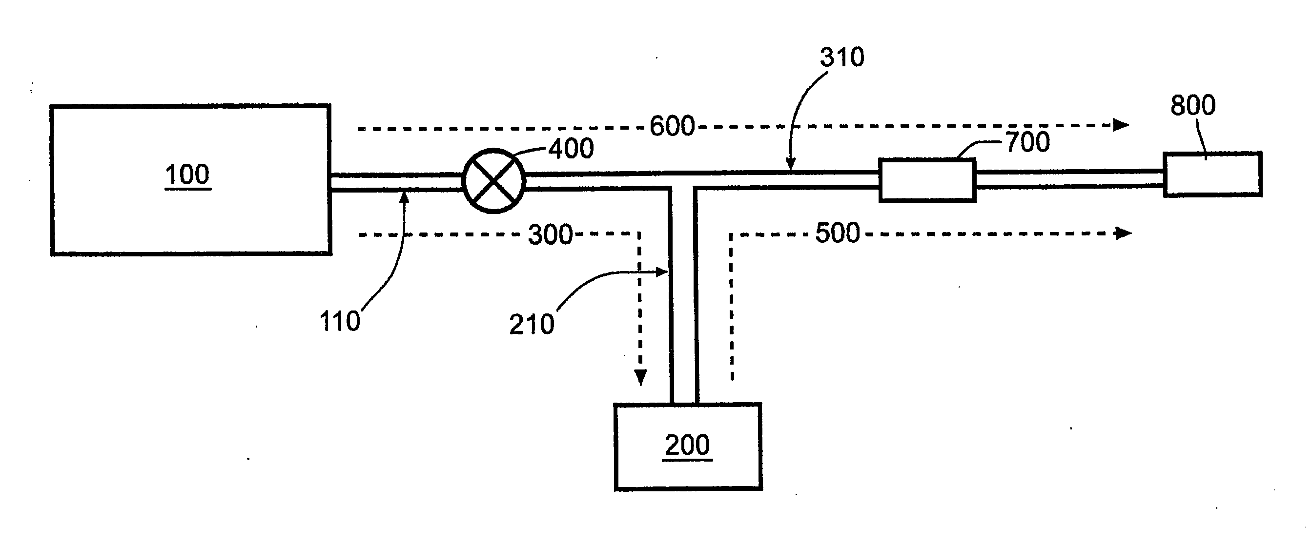
도 1a는 약물 또는 다른 유체를 일련의 제어된 부피의 투약량으로 투여하며, 투약량들 사이에는 유체의 연속 흐름이 있는 본 발명의 "기초-볼루스" 구체예의 도식도를 나타낸다. 이 장치는 실질적으로 일정한 압력(약물 저장소 압력, Pm)하에 약물 또는 다른 유체를 보유하는 약물 저장소(100)를 포함한다. 사용자가 제어된 부피의 투약량을 구동시켰을 때, 약물 저장소 압력이 약물 저장소(100)로부터 유체를 내보내고, 제 1 유체 유로(300)를 통해 공급 도관(110) 및 투약량 도관(210)을 통과하여 부피-제어식 투약량 저장소(200)로 흐르도록 한다. 투약량 저장소(200)가 채워졌을 때(도 1c에 예시된 대로), 투약량 저장소(200) 안의 유체는 약물 저장소 압력보다 더 높은 실질적으로 일정한 압력(투약량 저장소 압력, Pd, 이것은 반드시 일정하지는 않다)으로 가압되며, Pm:Pd의 비는 바람직한 주입 흐름 특성을 제공하도록 미리 정해져 제어된다. 제 1 유체 유로(300) 도중의 약물 저장소(100)와 투약량 저장소(200) 사이에 밸브(400)가 배치된다. 밸브(400)는 약물 저장소(100)에서부터 투약량 저장소(200)와 원단부(800)를 향해 하류 방향으로 유체 흐름을 허용하지만, 약물 저장소로 되돌아가는 반대 방향으로의 흐름은 막음으로써, 고압 투약량 저장소(200)에서부터 저압 약물 저장소(100)로 되돌아가는 유체 흐름을 방지하는 작용을 한다. 투약량 저장소 압력이 투약량 저장소(200)로부터 유체를 내보내고, 밸브(400)는 유체가 약물 저장소(100)로 되돌아 흐르는 것을 방지하며, 이로써 유체는 제 2 유체 유로(500)를 통해 선택적 투약량 도관(210)을 통과하고 송달 도관(310)을 통과하고 흐름 제한장치 요소(700)를 통과하여 장치의 원단부(800) 외부로 흐르게 된다. 흐름 제한장치 요소(700)는 투약량 저장소(200)에서부터 원단부(800) 외부까지 유체가 흐르는 주입 속도를 제어하며, 흐름 제한장치 요소(700)의 흐름-제한성은 투약량 저장소 압력과 함께 제어된 부피의 투약량에 바람직한 주입 흐름 특성을 제공하도록 미리 정해져 제어된다.1A shows a schematic of a “basal-bolus” embodiment of the present invention in which a drug or other fluid is administered in a series of controlled volumes of dosage, with a continuous flow of fluid between the dosages. The device includes a
투약량 저장소(200) 안팎으로의 흐름이 없는 제어된 부피의 투약량들 사이의 기간에는 약물 저장소 압력이 약물 저장소(100)로부터 유체를 내보내고, 제 3 유체 유로(600)를 통해 흐름 제한장치 요소(700)를 통과하여 장치의 원단부(800) 외부로 흐르게 한다. 흐름 제한장치 요소(700)는 약물 저장소(100)에서부터 원단부(800) 외부까지 유체가 흐르는 주입 속도를 제어하며, 흐름 제한장치 요소(700)의 흐름-제한성은 약물 저장소 압력과 함께 제어된 부피의 투약량들 사이의 연속 유체 흐름에 바람직한 주입 흐름 특성을 제공하도록 미리 정해져 제어된다.In the period between controlled volumes of doses without flow into and out of
송달된 유체 또는 저장소에 남아 있는 유체의 부피를 표시하는 표지나 마크가 투약량 저장소(200)에 위치될 수 있다. 추가하여, 이들 표지는 투약량이 투여를 완료할 시간 또는 투약량 송달까지 남은 시간의 양을 표시할 수도 있다.A label or mark indicating the volume of fluid delivered or fluid remaining in the reservoir may be located in the
도 1b는 기울어진 상태(비-구동 상태)의 비어 있는 투약량 저장소(200)를 예시한다. 이 상태에서는 투약량 저장소가 유체 압력에 어떠한 영향도 주지 못한다. 도 1c는 구동된 투약량 저장소를 예시한다. 저장소는 제어된 부피의 투약량을 넘지 않을 때 저장소가 열리도록 구성된다. 투약량 저장소(200)를 구동시키기 위해서는 사용자가 힘(F)을 발휘하여 저장소를 열어야 한다. 이것은 유체가 약물 저장소(100)에서부터 투약량 저장소(200)까지 흐르는 것을 허용한다. 일단 투약량 저장소(200)가 가득 차서 사용자가 구동장치를 해제시키면, 투약량 저장소는 약물 저장소 압력보다 더 높은 제어된 압력 Pd를 발휘한다.1B illustrates an
도 1d 및 1e는 투약량 저장소(200)의 개방 및 폐쇄를 예시하는데, 여기에는 투약량 도관(210)이 없다. 이 구성에서 유체는 공급 도관(110)과 체크 밸브(400)를 통과하여 약물 저장소(100)에서부터 투약량 저장소(200)까지 직접 흐른다. 도 1d에 도시된 대로, 투약량 저장소가 비어 있을 때는 우회로 흐름 영역(208)에 의하여 유체의 연속 흐름이 투약량 저장소를 우회하여 흐른다. 도 1e에 도시된 대로, 투약량 저장소(200)가 구동되었을 때는 송달 도관(310)으로만 흐른다. 우회로 흐름 영역(208)은 투약량 저장소의 영역이며, 여기서 유체는 공급 도관(110)을 거쳐 들어가 송달 도관(310)을 거쳐 나온다. 그러나, 우회로 흐름 영역(208)이 반드시 투약량 저장소의 일부일 필요는 없다. 투약량 저장소(200)와 나란히 있는 공급 도관(110)과 송달 도관(310)을 연결하는 분리된 관일 수도 있다.1D and 1E illustrate the opening and closing of the
유속 프로파일이 도 2에 도시된다. 약물 저장소(100)의 실질적으로 일정한 압력 Pm에서 실질적으로 일정한 기초 유속이 원단부(800)에서 환자에게 송달된다. 이것은 도 2에서 t1 이전의 시간에 나타낸 것이다. 시간 t1은 사용자가 투약량 저장소의 구동을 완료한 순간으로서 정의된다. t1 직후 투약량 저장소는 가득 차게 되고 압력은 Pd로 더 높아진다. 시간 t2는 t1 이후 투약량 저장소가 비게 된 순간으로서 정의된다. t1과 t2 사이의 시간 기간에 투약량 저장소는 흐름 제한장치 요소(700)의 유체 상류를 가압하고, 이것은 유속을 기초 유속에서 더 높은 볼루스 유속으로 증가시킨다. 투약량 저장소가 그 내용물을 전부 송달하여 t2에서 저장소가 비자마자 바로 유체 압력은 Pm으로 다시 강하되고 유속은 기초 유속으로 다시 강하된다. 이 그래프에서 음영 면적이 부피-제어된 투약량을 예시한다. 사용자는 다수의 투약량을 송달할 수 있는데, 이에 따라 도 2에 예시된 흐름 프로파일이 만들어진다.The flow rate profile is shown in FIG. At a substantially constant pressure Pm of the
약물 저장소(100)Drug Depot (100)
약물 저장소(100)는 유체를 수용할 수 있는 저장소를 제공하고 유체에 기지 압력을 적용하고 압력하에 유체를 보관하고 압력하에 유체를 투여하는 어떤 다수의 공지 기술을 이용할 수 있다. 본 발명에서 사용하기 적합한 약물 저장소를 제공하는 현행 장치의 예는 제한은 없지만 Beeline MotIV(스프링 구동 시린지 스타일 펌프, 미국 의장특허 제453,830호), OutBound DSI(진공 구동 시린지 스타일 펌프, 미국 특허 제5,135,500호), 및 Accufuser(벌룬 스타일 펌프, 미국 특허 제6,024,724호)를 포함하며, 이것들은 모두 McKinley Medical에 의해 판매된다.
시스템에는 약물 저장소(100)로 유체가 도입되는 충전 포트가 필요하다. 이 충전 포트는 Luer 연결장치, 격벽(바늘이나 못으로 뚫리는), 또는 다른 적합한 연결장치의 형태를 취할 수 있다. 이 구체예에서, 충전 포트는 암 Luer-자물쇠 연결장치와 한-방향 밸브로 구성되고, 시린지 또는 충전 펌프의 수 Luer 종결장치가 충전 포트의 암 Luer 연결장치에 연결되며, 압력하에 유체가 시린지 또는 충전 펌프로부터 약물 저장소로 전달되는데, 이때 전달압력은 약물 저장소 압력을 극복할 만큼 충분하고, 시린지 또는 충전 펌프와 충전 포트의 연결이 해제되었을 때는 한-방향 밸브가 작동하여 약물 저장소 안의 유체가 충전 포트로 되돌아 흐르는 것을 방지한다. 충전 포트는 약물 저장소(100) 내부에 위치될 수도 있고, 또는 제 1 유체 유로(300) 도중의 약물 저장소(100)와 밸브(400) 사이에 배치될 수도 있다.The system requires a filling port through which fluid is introduced into the
장치가 선택될 특정한 치료요법의 필요에 따라서, 약물 저장소(100)는 필요한 수의 제어된 부피의 투약량 및 투약량들 사이의 연속 유체 흐름을 제공하기 위한 충분한 유체를 보유할 정도의 크기이다. 예를 들어, 10mL 저장소는 약 6일 동안 4시간 마다 한 번씩 0.2mL로 제어된 부피 투약량이 보충되는 0.02mL/hr 연속 흐름을 필요로 하는 치료요법을 위한 충분한 용량을 제공하고; 100mL 저장소는 약 1일 동안 1시간에 한 번씩 2mL로 제어된 부피 투약량이 보충되는 2mL/hr 연속 흐름을 필요로 하는 치료요법을 위한 충분한 용량을 제공하고; 350mL 저장소는 약 2일 동안 2시간 마다 한 번씩 5mL로 제어된 부피 투약량이 보충되는 5mL/hr 연속 흐름을 필요로 하는 치료요법을 위한 충분한 용량을 제공하고; 1000mL 저장소는 약 5일 동안 8시간 마다 한 번씩 50mL로 제어된 부피 투약량이 보충되는 2mL/hr 연속 흐름을 필요로 하는 치료요법을 위한 충분한 용량을 제공할 것이다.Depending on the needs of the particular therapy for which the device is to be selected, the
약물 저장소(100)는 시스템을 통해 유체를 내보내고 주입 부위의 어떤 배압(예를 들어, 장치에서 먼 쪽의 작은 관통구 주입 카테테르, 또는 환자 혈관 시스템 내 압력)을 극복할 만큼의 충분한 압력을 발생시킨다. 전형적인 주입 용도는 적어도 3-4psi의 압력이 필요하고, 더욱 통상적으로 (상기 언급된 Beeline, OutBound, 및 Accufuser 제품에서와 같이) 의약 저장소는 5-15psi의 범위의 압력을 발생시키며, 어떤 용도에서는 20-40psi의 고압, 또는 심지어 더 높은 고압이 바람직하다.
투약량 저장소(200)Dosage Storage (200)
투약량 저장소(200)는 약물 저장소(100)보다 더 높은 유체 압력을 발생시키는 압력-발생 메커니즘 또는 압력 공급원을 포함한다. 추가하여, 투약량 저장소(200)는 일시적으로 압력 공급원을 억제하여, 투약량 저장소 내부의 압력을 감소시키거나 제거하고, 제 1 유체 유로(300)를 가로질러 약물 저장소(100)로부터의 압력 강하를 만들고, 유체 흐름을 유발하여 투약량 저장소(200)를 채우는 구동장치를 포함한다. 구동장치를 사용하여 투약량 저장소(200)가 채워진 후, 압력 공급원은 투약량 저장소(200)의 압력을 약물 저장소(100)보다 높게 함으로써, 압력하에 투약량 저장소(200)로부터 흐름 제한장치 요소(700)를 통과해 흐르는 유체가 압력하에 약물 저장소(100)로부터 동일한 흐름 제한장치 요소(700)를 통과해 흐르는 유체보다 빠른 속도로 흐르게 한다. 투약량 저장소 압력과 약물 저장소 압력의 비는 제어된 부피의 투약량들의 주입 속도와 제어된 부피의 투약량들 사이의 연속 흐름의 주입 속도의 비를 결정한다. 예를 들어, 만일 투약량 저장소(200)가 12psi의 유체 압력을 발생시키고 약물 저장소(100)가 6psi의 유체 압력을 발생시킨다면, 압력 비는 2가 되고, 이때 부피-제어된 투약량은 부피-제어된 투약량들 사이의 연속 기초 흐름보다 2배의 주입 속도로 주입될 것이다. 압력 비가 1.5라면, 부피-제어된 투약량은 연속 흐름보다 50% 더 빠르게 주입될 것이다. 압력 비가 4라면, 부피-제어된 투약량은 연속 흐름보다 4배 더 빠르게 주입될 것이다.
투약량 저장소(200)는 유체를 수용할 수 있는 저장소를 제공하고 유체에 기지 압력을 적용하고 압력하에 유체를 보관하고 압력하에 유체를 투여하는 어떤 다수의 공지 기술을 이용할 수 있으며, 단 유체에 압력을 적용하는 메커니즘은 힘(F)을 일시적으로 적용하여 저장소를 개방함으로써 선택적으로 그리고 일시적으로 사용자에 의해 제거될 수 있다. 본 발명에서 투약량 저장소로 사용되는 적합한 저장소의 예는 제한은 없지만 스프링 압력 공급원(상기 언급된 Beeline MotIV 펌프형의 약물 저장소와 유사)에 의해, 또는 진공 메커니즘(상기 언급된 OutBound DSI 펌프형 약물 저장소와 유사)에 의해서 가압되는 시린지 스타일 저장소를 포함한다. 예를 들어, 구동장치는 손으로 스프링을 압축하거나 진공 챔버를 팽창시킴으로써 시린지 플런저로부터의 가압력을 일시적으로 억제한 다음, 시린지 플런저를 힘을 주어 뒤로 끌어당겨서 시린지가 채워지도록 할 수 있는 슬라이드, 레버 또는 다른 메커니즘일 수 있다. 대안으로서, 백 스타일 저장소(상기 언급된 Accufuser 펌프형의 볼루스 1회 분량 저장소와 유사)가 스프링에 의해서 가압될 수 있다. 여기서도 또한 구동장치(예를 들어, 슬라이드, 레버, 또는 다른 메커니즘)를 이용, 사용자가 손으로 스프링을 압축함으로써 백으로부터의 가압력을 억제하거나 제한하여 백을 채울 수 있다. 다른 구체예에서, 풀무 스타일 저장소가 적합한 압력 공급원(예를 들어, 스프링 또는 압축 기체)에 의해서 가압될 수 있다. 구동장치를 이용하여 사용자는 가압 메커니즘에 대해 열리도록 풀무를 손으로 고정하여 풀무를 채울 수 있다. 유사하게, 격판 상에 힘-적용 로드 베어링을 구비한 회전-격판 스타일 저장소가 디자인될 수 있고, 이것은 어떤 적합한 메커니즘(예를 들어, 스프링, 신축형 탄성 부재, 또는 공기 압력)에 의해 구동되며, 사용자가 손으로 힘-적용 로드를 뒤로 끌어당겨 격판의 가압력을 제거하여 저장소를 채울 수 있는 슬라이드, 레버, 또는 다른 메커니즘을 구비한다.
장치가 선택될 특정한 치료요법의 필요에 따라서, 투약량 저장소(200)는 1회의 제어된 부피의 투약량을 위한 충분한 유체를 보유할 정도의 크기이다. 예를 들어, 0.2mL 또는 0.3mL 투약량 저장소는 진통억제 치료요법을 위한 전형적인 투약량 부피를 제공하고; 0.5mL 또는 1mL 투약량 저장소는 IV류 통증 관리 용도를 위한 전형적인 투약량 부피를 제공하고; 2mL, 5mL, 또는 10mL 투약량 저장소는 신경 블럭 통증 관리 용도를 위한 전형적인 투약량 부피를 제공하고; 10mL, 25mL, 50mL, 또는 100mL 투약량 저장소는 IV류 항생제 용도를 위한 전형적인 투약량 부피를 제공할 것이다.Depending on the needs of the particular therapy for which the device is to be selected, the
투약량 저장소 부피는 제조 과정에서 고정될 수도 있고, 또는 사용자에 의해서 선택가능할 수도 있다. 부피-제어식 투약량 저장소의 사용자-선택형 메커니즘의 예는 제한은 없지만 시린지 스타일 투약량 저장소 안으로 플런저가 이동하는 것을 제한하고 사용자가 스크루의 다이얼을 맞춰서 원하는 부피에 멈추게 할 수 있는 스크루-장착 마개; 백 스타일 투약량 저장소에서 연성 백의 한 측면에 대해 지탱된 이동식 강성 판으로, 강성 판의 뒤에 슬라이드식 쐐기가 있어서 강성 판의 이동을 제한하고 사용자는 쐐기를 안팎으로 움직여 원하는 부피에 맞춰 강성 판을 제한 이동시켜 위치시킬 수 있는 이동식 판을 포함한다. 외부 하우징 상의 선택적인 눈금 표시는 구동장치(예를 들어, 슬라이드 또는 레버)의 이동과 일치되며, 이로써 사용자는 투약량 저장소가 어느 정도 개방되었는지 육안검사할 수 있고, 구동장치의 이동을 선택적으로 제한하여 원하는 부피를 달성할 수 있다.Dosage reservoir volume may be fixed during the manufacturing process or may be selectable by the user. Examples of user-selectable mechanisms for volume-controlled dosage reservoirs include, but are not limited to, screw-mount stoppers that restrict the movement of the plunger into the syringe-style dosage reservoir and allow the user to align the screw's dial to stop at the desired volume; A movable rigid plate held against one side of the flexible bag in the bag style dosage reservoir, with a sliding wedge behind the rigid plate to limit the movement of the rigid plate and the user to move the wedge in and out to limit the rigid plate to the desired volume. And a removable plate that can be positioned. Optional tick marks on the outer housing coincide with the movement of the drive (eg slide or lever), thereby allowing the user to visually check how much the dose reservoir is open, and selectively limit the movement of the drive The desired volume can be achieved.
제 1 유체 유로(300)First
도 1a 내지 1e 및 도 2에 도시된 한 구체예에서, 제 1 유체 유로(300)는 주입 세트에서 통상 사용되는 어떤 길이의 의료-등급 PVC 관이나 다른 유사한 관 등의 연성 관의 형태를 취할 수 있다. 다른 구체예에서, 제 1 유체 유로(300)는 성형되거나 기계가공된 강성 채널(예를 들어, 이 경우에, 약물 저장소(100), 투약량 저장소 (200) 및 제 1 유체 유로(300)는 모두 일체형 하우징 또는 블럭 내에 형성된다), 또는 연성 채널(예를 들어, 이 경우에, 약물 저장소(100) 또는 투약량 저장소(200)는 2장의 연성 시트를 함께 용접함으로써 실질적으로 평평한 백으로 형성되고, 이때 제 1 유체 유로(300)는 2장의 연성 시트 사이에 용접된 영역으로서 형성된다)의 형태를 취할 수 있다.In one embodiment shown in FIGS. 1A-1E and 2, the first
제 1 유체 유로(300)는 연속된 길이의 관 또는 연속된 성형 채널과 같은 하나의 일체형 유닛으로 구성될 수 있다. 대안으로서, 제 1 유체 유로(300)는 함께 연결된 몇 개의 부재들로 구성될 수 있다. 이 구체예에서, 제 1 유체 유로(300)는 약물 저장소(100)와 밸브(400) 사이의 관(공급 도관(110)), 밸브(400) 구성요소를 통과하는 성형 유로, 밸브(400)와 삼발형 어댑터 구성요소(350) 사이의 관(추가 공급 도관(110)), 삼발형 어댑터 구성요소(350)를 통과하는 성형 유로, 및 삼발형 어댑터 구성요소(350)와 투약량 저장소(200) 사이의 관으로 구성된다. 약물 저장소로부터 유체의 흐름을 중단시킬 수 있는 스냅식 클램프(111)가 공급 도관(110) 도중의 어느 곳에 위치될 수 있다. 스냅식 클램프(111)는 상업 표준형 스냅식 클램프일 수도 있고, 또는 슬라이드식 클램프, 밸브, 또는 유체 흐름을 중단시킬 수 있는 어떤 수단의 형태를 취할 수도 있다.The first
제 1 유체 유로(300)는 약물 저장소(100) 및 투약량 저장소(200)에 영구적으로 연결될 수 있으며, 예를 들어 각 단부에 결합된 어떤 길이 또는 길이들의 관이 그것이다. 대안으로서, 제 1 유체 유로(300)는 시스템에 탈착식으로 연결된 부재일 수 있으며, 예를 들어 약물 저장소(100), 밸브(400), 또는 투약량 저장소(200) 상의 Luer 연결장치와 짝을 이룬 Luer 연결장치에서 종료하는 어떤 길이 또는 길이들의 관이 그것이다.The first
밸브(400)
밸브(400)의 유일한 목적은 투약량 저장소(200)로부터 약물 저장소(100)로의 유체 흐름을 방지하기 위한 것이다. 밸브(400)는 약물 저장소(100)로부터 투약량 저장소(200)로의 연속 유체 흐름을 방지하기 위해서는 필요하지 않은데, 왜냐하면 이것은 두 저장소 사이의 차이 나는 양압에 의해 방지되기 때문이다(사용자가 메커니즘을 구동시켜 투약량 저장소 압력을 제거할 때까지). 도 1에 도식적으로 묘사된 장치의 구체예에서, 밸브(400)는 약물 저장소(100)로부터 제 3 유체 유로(600)를 통과하는 유체 흐름을 허용하기 위해서 필요하다. 본 발명의 장치의 이 구체예에서, 밸브(400)는 제 1 유체 유로(300) 도중에 배치되며, 이로써 밸브는 정상적으로 열려 약물 저장소(100)로부터 유체 유로의 먼 쪽 지점으로의 흐름을 허용하고, 수동적으로 닫혀서 유체 유로의 먼 쪽 지점으로부터 약물 저장소(100)로 되돌아가는 흐름을 방지한다. 밸브(400)는 오리너구리 스타일 밸브, 볼 스타일 밸브, 원반 스타일 밸브 또는 유사물과 같은 정상-개방 한-방향 체크 밸브를 제공하는 다수의 공지된 기술 중 어느 것을 이용할 수 있다.The sole purpose of the
제 2 유체 유로(500)Second
제 2 유체 유로(500)는 주입 세트에서 통상 사용되는 어떤 길이의 의료-등급 PVC 관이나 다른 유사한 관 등의 연성 관의 형태를 취할 수 있다. 다른 구체예에서, 제 2 유체 유로(500)는 성형되거나 기계가공된 강성 채널(예를 들어, 이 경우에, 투약량 저장소(200), 제 2 유체 유로(500) 및 원단부(800)는 모두 일체형 하우징 또는 블럭 내에 형성된다), 또는 연성 채널(예를 들어, 이 경우에, 투약량 저장소(200)는 2장의 연성 시트를 함께 용접함으로써 실질적으로 평평한 백으로 형성되고, 이때 제 2 유체 유로(500)는 2장의 연성 시트 사이에 용접된 영역으로서 형성된다)의 형태를 취할 수 있다. 두 저장소 중 어느 것으로부터 유체의 흐름을 중단시킬 수 있는 슬라이드식 클램프(311)가 공급 도관(310) 도중의 어느 곳에 위치될 수 있다. 이것은 상업적으로 이용가능한 표준형 슬라이드식 클램프, 스냅식 클램프, 밸브, 또는 유체 흐름을 중단시킬 수 있는 어떤 수단일 수 있다.The second
제 2 유체 유로(500)는 연속하는 길이의 관 또는 연속하는 성형 채널과 같은 하나의 일체형 유닛으로 구성될 수 있다. 대안으로서, 제 2 유체 유로(500)는 함께 연결된 몇 개의 부재들로 구성될 수 있다. 제 2 유체 유로(500)는 투약량 저장소(200)와 삼발형 어댑터 구성요소(350) 사이의 관, 삼발형 어댑터 구성요소(350)를 통과하는 성형 유로, 삼발형 어댑터 구성요소(350)와 공기-제거 필터 구성요소 (710) 사이의 관, 공기-제거 필터 구성요소(710)를 통과하는 성형 유로, 공기-제거 필터 구성요소(710)와 원단부(800) 사이의 관(흐름 제한장치 구성요소(700)를 포함하는 관), 및 원단부(800)를 통과하는 성형 유로를 포함한다.The second
제 2 유체 유로(500)는 제 1 유체 유로(300)와 공통 요소들을 공유할 수 있다. 예를 들어, 상술한 설명에 있어서, 투약량 저장소(200)와 삼발형 어댑터 구성요소(350) 사이의 관은 제 1 유체 유로(300)와 제 2 유체 유로(500)의 모두의 요소이며, 그 방향에 따라서 유체는 상기 관을 통과해 흐르게 된다(유체가 투약량 저장소(200)를 향해 흐를 때, 관은 제 1 유체 유로(300)의 일부가 되고, 유체가 투약량 저장소(200)로부터 흘러나올 때, 관은 제 2 유체 유로(500)의 일부가 된다). 제 2 유체 유로(500)는 투약량 저장소(200)에 영구적으로 연결될 수 있다. 대안으로서, 제 2 유체 유로(500)는 시스템에 탈착식으로 연결된 부재일 수 있으며, 예를 들어 투약량 저장소(200) 상의 Luer 연결장치와 짝을 이룬 Luer 연결장치 근처까지의 어떤 길이의 관이 그것이다.The second
제 3 유체 유로(600)
제 3 유체 유로(600)는 주입 세트에서 통상 사용되는 어떤 길이의 의료-등급 PVC 관이나 다른 유사한 관 등의 연성 관의 형태를 취할 수 있다. 다른 구체예에서, 제 3 유체 유로(600)는 성형되거나 기계가공된 강성 채널(예를 들어, 이 경우, 약물 저장소(100), 제 3 유체 유로(600) 및 원단부(800)는 모두 일체형 하우징 또는 블럭 내에 형성된다), 또는 연성 채널(예를 들어, 이 경우에, 약물 저장소(100) 및 투약량 저장소(200)는 2장의 연성 시트를 함께 용접함으로써 실질적으로 평평한 백으로 형성되고, 이때 제 1 유체 유로(300)는 2장의 연성 시트 사이에 용접된 영역으로서 형성된다)의 형태를 취할 수 있다.The third
제 3 유체 유로(600)는 연속하는 길이의 관 또는 연속하는 성형 채널과 같은 하나의 일체형 유닛으로 구성될 수 있다. 대안으로서, 제 3 유체 유로(600)는 함께 연결된 몇 개의 부재들로 구성될 수 있다. 바람직하게, 제 3 유체 유로(600)는 약물 저장소(100)와 밸브(400) 사이의 관, 밸브(400) 구성요소를 통과하는 성형 유로, 밸브(400)와 삼발형 어댑터 구성요소(350) 사이의 관, 삼발형 어댑터 구성요소 (350)를 통과하는 성형 유로, 삼발형 어댑터 구성요소(350)와 공기-제거 필터 구성요소(710) 사이의 관, 공기-제거 필터 구성요소(710)를 통과하는 성형 유로, 공기-제거 필터 구성요소(710)와 원단부(800) 사이의 관(흐름 제한장치 구성요소(700)를 포함하는 관), 및 원단부(800)를 통과하는 성형 유로를 포함한다.The third
제 3 유체 유로(600)는 제 1 유체 유로(300) 및 제 2 유체 유로(500)와 공통 요소들을 공유할 수 있다. 예를 들어, 상술한 설명에 있어서, 삼발형 어댑터 구성요소(350)의 위쪽의 제 1 유체 유로(300)의 모든 요소들과 삼발형 어댑터 구성요소 (350)의 아래쪽의 제 2 유체 유로(500)의 모든 구성요소들은 또한, 제어된 부피의 투약량이 구동되었는지에 따라서 제 3 유체 유로 (600)의 요소가 된다(제어된 부피의 투약량이 채워지거나 주입될 때, 상기 유체 유로 요소들은 제 1 또는 제 2 유체 유로를 구성하고, 제어된 부피의 투약량들 사이에 연속 흐름이 흐를 때, 상기 유체 유로 요소들은 제 3 유체 유로를 구성한다). 제 1 및 제 2 유체 유로에 대해 설명한 대로, 제 3 유체 유로(600)는 시스템에 영구적으로 연결될 수도 있고, 또는 시스템에 탈착식으로 연결된 부재일 수도 있다.The third
흐름 제한장치 요소(700)Flow Limiter Element (700)
흐름 제한장치 요소(700)는 흐름 제한장치 요소(700)를 통과하는 유체 유속이 흐름 제한장치 요소(700)를 가로지른 압력 강하에 비례하는 기지의 흐름 제한을 제공해야 한다. 본 발명에서 흐름 제한장치 요소(700)로 사용되는 적합한 흐름 제한장치의 예는 제한은 없지만, 판 두께, 구경 및 에지 샤프니스가 제어된 박판 흐름 구멍; 내경 및 길이가 제어된 어떤 길이의 모세관; 공극경 및 습윤면적이 제어된 다공막 또는 유사한 다공성 장벽을 포함한다. 이들 종류의 흐름 제한장치는 흐름 제한장치를 통과하는 유속이 흐름 제한장치를 가로지른 압력차에 실질적으로 비례하도록 유체 흐름에 대한 저항성을 제공한다는 원리에 따라 기능하며, 제조 과정에서 흐름 제한장치의 제어된 매개변수들을 조작함으로써, 미리 정해진 약물 저장소 압력 및 투약량 저장소 압력과 흐름 제한장치 요소(700)가 조화되어 원하는 주입 유속 매개변수가 달성될 수 있다.The flow
대체로 흐름 제한장치 요소(700)의 바로 상류에 공기-제거 필터(710)를 위치시키는 것이 바람직하다. 공기-제거 필터(710)는 상업적으로 이용가능한 각종 표준품들일 수 있으며, 송달 도관(310)과 일렬로 위치된다. 그러나, 이것은 흐름 제한장치 요소(700)와 일체화될 수도 있고, 또는 흐름 제한장치 요소(700)의 상류에 위치하기만 한다면 송달 도관(310) 도중의 어느 장소에라도 있을 수 있다. It is generally desirable to locate the air-
원단부Fabric (800)(800)
본 장치의 원단부(800)는 장치와 주입 부위 사이의 유체 연결을 제공한다. 예를 들어, 원단부는 Luer-자물쇠 연결장치의 형태를 취할 수 있다. 대안으로서, 원단부(800)는 바늘, 주입 카테테르 또는 다른 적합한 연결장치를 포함할 수 있다. 이들 모두는 각종의 "환자 연결부"로서 일반적으로 해석되어야 한다.The
도 3은 일련의 제어된 부피의 약물 투약량의 투여만을 제공하며 투약량들 사이에 유체의 연속 흐름을 제공하지 않는 본 발명의 "볼루스-단독" 구체예의 도식도이다. 이 장치는 압력(약물 저장소 압력)하에 약물 또는 다른 유체를 보유하는 약물 저장소(100)와 채워졌을 때 약물 저장소 압력보다 큰 실질적으로 일정한 압력(투약량 저장소 압력)하에 약물 또는 다른 유체를 보유하는 투약량 저장소(200)를 포함한다. 약물 저장소(100) 및 투약량 저장소(200)는 제 1 유체 유로(300)에 의해 유체 연통되어 연결된다. FIG. 3 is a schematic of a “bolus-only” embodiment of the present invention that provides administration of a series of controlled volumes of drug dosage only and does not provide a continuous flow of fluid between doses. The device comprises a
제 1 유체 유로(300) 도중의 약물 저장소(100)와 투약량 저장소(200) 사이에 밸브(400)가 배치된다. 사용자가 제어된 부피의 투약량을 구동시켰을 때, 약물 저장소와 투약량 저장소 사이의 압력 강하가 일어나 유체를 약물 저장소(100)로부터 내보내고, 제 1 유체 유로(300)를 통과해 부피-제어식 투약량 저장소(200)로 흐르게 하여 투약량 저장소(200)가 채워진다. 사용자는 선택적으로 그리고 일시적으로 제어된 부피의 투약량을 구동시켜 투약량 저장소(200)로부터의 압력 공급원을 제거하는데, 이것은 도 1에 도식적으로 묘사한 장치 구체예에 대한 상세한 설명에서 설명된 바와 같다. 만일 저장소가 비었을 때 어떤 우회로 흐름을 방지하도록 투약량 저장소(200)가 구성된다면, 도 1에 도식적으로 묘사된 장치 구체예에 대한 상세한 설명에서 설명된 대로, 밸브(400)는 단지 체크 밸브로서만 사용되어야 한다. 만일 저장소가 비었을 때 투약량 저장소(200)가 어떤 우회로 흐름을 허용한다면, 사용자에 의해 열릴 때만을 제외하고는 밸브(400)는 약물 저장소(100)로부터 나오는 유체 흐름을 방지하는 정상-폐쇄형으로 작용해야 한다. 이 기능을 달성하기 위하여, 밸브(400)는 핀치 스타일 밸브, 스탑콕 스타일 밸브 또는 유사물과 같은 사용자에 의해 구동되었을 때를 제외하고는 닫혀 있는 밸브를 제공하는 다수의 공지된 기술 중 어느 것을 이용할 수 있다.A
도 3에 도식적으로 묘사된 장치 구체예에 대한 나머지 상세사항은 본 발명의 장치의 이 구체예에는 제 3 유체 유로(600)가 제공되지 않는다는 것을 제외하고는(즉, 투약량 저장소를 우회하는 흐름을 제공하지 않는다) 도 1에 대해 상세히 논의된 바와 동일하다.The remaining details of the device embodiment depicted diagrammatically in FIG. 3 refer to flows bypassing the dosage reservoir, except that a third
"볼루스-단독" 디자인의 다른 구체예는 비-가압 약물 저장소를 가지도록 구성될 수 있다. 이 구체예는 도 3에 관해 상기 설명된 구체예와 동일하며, 다만 다음과 같은 차이점이 있다: (a) 약물 저장소(100)는 주위 압력이다; 및 (b) 사용자는 선택적으로 그리고 일시적으로 제어된 부피의 투약량을 구동시켜 투약량 저장소 (200)로부터의 압력 공급원을 제거하면서 동시에 이 저장소를 강제 개방한다. 저장소를 강제 개방하는 것은 챔버 안에 진공을 일으킨다. 약물 저장소(100)가 주위 압력이므로 유체는 더 낮은 압력의 투약량 저장소(200)를 향해 흐를 것이다.Another embodiment of the "bolus-only" design can be configured to have a non-pressurized drug reservoir. This embodiment is identical to the embodiment described above with respect to FIG. 3, with the following differences: (a)
도 4a 및 4b는 도 1 및 도 3에 도식적으로 묘사된 본 발명에 사용되는 적합한 투약량 저장소(200)의 많은 가능한 물리적 구체예들 중 하나의 단면도를 나타낸다. 투약량 저장소(200)의 이 특정한 구체예는 스프링으로 가압된 시린지를 포함하며, 시린지 플런저로부터 스프링 힘을 선택적으로 제거하기 위한 슬라이더 메커니즘을 갖는 하우징 내부에 고정된다. 도 5a 및 5b는 내부 메커니즘이 보이지 않는 장치를 예시한다. 이 특정한 구체예의 도해에 대해서는 도 6을 참조하며, 이것은 현재 제조되고 있는 중이다. 도 4a 및 4b에 묘사된 투약량 저장소(200)는 하우징(220) 내부에 고정된 시린지(209)로 구성된다. 스프링(230)이 시린지를 가압하고, 슬라이더(240)는 사용자가 선택적으로 그리고 일시적으로 스프링 힘을 제거하여 시린지(209)로부터 압력을 제거하도록 허용한다. 시린지(209)의 이러한 압력-제거에 의해 투약량 저장소(200)의 유체-보유 챔버(215) 부분이 채워진다. 사용자는 슬라이더(240)를 움켜쥐고 표면(테이블 위, 침상, 의자 또는 사용자의 신체)에 대해 하우징(220)의 단부(222)를 가압하고 하우징(220)에 관하여 (표면을 향해) 슬라이더(240)를 축 이동하여 움직임으로써 시린지(209)에서 압력을 제거한다.4A and 4B show cross-sectional views of one of many possible physical embodiments of a
바람직하게, 시린지는 의료 부문에서 통상 사용되는 전형적인 표준형 시린지이며, 함께 시린지 플런저(214)를 형성하는 플런저 시일(212)과 플런저 로드(213) 및 시린지 통(211)을 포함한다. 시린지 플런저(214)는 시린지 통(211) 내부에 슬라이드 방식으로 배치되어 유체-보유 챔버(215)를 형성하고, 유체 도관(216)이 유체-보유 챔버(215) 안팎으로의 유체의 진입과 방출을 제공한다. 선택적으로, 시린지는 전형적인 표준형 시린지와 마찬가지로 시린지 통(211) 상에 눈금 표시를 가질 수 있다. 도 4a 및 4b는 시린지(209)의 유체 도관(216) 부분에 연결된 어떤 길이의 투약량 도관(210)을 묘사한다. 이 투약량 도관(210)은 연성 관으로 만들어지는데, 투약량 저장소(200)와 장치의 나머지 요소들 사이의 연결을 제공하는 것으로, 도 1a 내지 1c 및 도 3과 관련하여 논의되고 예시된 제 1 및 제 2 유체 유로의 일부분이다.Preferably, the syringe is a typical standard syringe commonly used in the medical sector and includes a
도 4a 및 4b에 묘사된 대로, 하우징(220)은 시린지(209)를 둘러싸고 있으며, 하우징(220)의 개방된 단부에는 하우징(220)을 완전히 에워싼 캡(221)이 있다. 도 4c에 도시한 대로, 캡(221)은 스냅식이며, 하우징의 단부에서 스냅식 맞물림 구조 (227)와 함께 제자리에 고정된다. 도 4d에서 도시한 대로, 시린지 플런저(214) 상의 엄지손가락 누름장치 표면(237)과 짝을 이룬 캡쳐 구조(228)가 캡(221)과 일체화되어 있으며, 이것은 시린지 플런저(214)를 제자리에 고정하는 작용을 함으로써 하우징(220)에 관한 시린지 플런저(214)의 축 이동을 실질적으로 방지한다. 또한, 시린지 통(211)과 슬라이더(240)의 이동을 제한하는 스탠드오프(224)가 캡(221)과 일체화되어 있다. 플런저 시일(212)이 시린지 통(211)의 단부에서 중단될 수 있지만, 이것은 수동 상태의 스프링(230)에 의해 제공되는 시린지 통(211)에 대한 플런저 시일(212)의 지속적인 압축력 때문에, 시린지(211) 재료가 시간에 따라 변형되도록 조장되므로 바람직하지 않다. 따라서, 스탠드오프(224)와 같은 다른 이동 중단장치가 바람직하다.As depicted in FIGS. 4A and 4B, the
하우징(220)은 바람직하게 사출성형 플라스틱으로 형성된다. 하우징(220)은 스프링을 압축하기 위해 사용자에 의해 적용된 힘을 지지할 만큼의 충분한 강도와 사용자가 슬라이더(240)에 너무 많은 힘을 적용함으로써 장치가 의도치 않게 파손되지 않도록 보장할 수 있는 안전성 구조를 가져야 한다. 하우징(220)에 필요한 전형적인 강도는 10-25 파운드 범위이다.
하우징(220)은 시린지(209)가 눈에 보이지 않도록 불투명할 수도 있고, 또는 시린지가 보이도록 투명하거나 반투명할 수도 있다. 만일 하우징(220)이 시린지(209)를 눈에 보이지 않도록 감추고 있다면, 개구나 창이 시린지 통(211) 근처의 영역에서 하우징의 벽에 제공되어, 사용자가 유체-보유 챔버(215) 또는 시린지 통(211) 상의 눈금 표시를 볼 수 있어서 투약량 저장소(200) 안의 유체량을 육안 측정할 수 있다. 대안으로서, 하우징(220)의 외부 표면이 슬라이더(240)의 위치에 따라 판독될 수 있는 투약량 저장소(200) 안의 유체량을 나타내는 눈금 표시를 포함할 수 있다. 하우징(220)의 한 단부(222)는 사용자가 슬라이더(240)를 움직였을 때 표면을 밀도록 배치된다. 하우징(220)은 하우징 내부의 시린지(209)와 하우징 외부에 배치된 제 1 및 제 2 유체 유로 사이에 유체 연결을 제공하는 투약량 도관(210)이 통과하는 개구(223)를 제공한다. 하우징(220)은 또한 시린지 통(211)의 이동을 제한하는 이동 중단 릿지(229)를 포함한다. 사용자가 슬라이더(240)를 잡아당김에 따라, 시린지 통은 엄지손가락 누름장치 구조(237)가 이동 중단 릿지(229)에 접촉할 때까지 이동된다. 이 두 가지 이동 중단장치(229) 및 스탠드오프(224)가 시린지 통의 이동을 양 방향으로 제한함으로써, 유체-보유 챔버(215)의 부피가 정확하게 제어된다.The
The
도 4e에 도시한 대로, 시린지 플런저(214)를 넘는 시린지 통(211)의 이동을 제한하기 위해 이격 구성요소(226)가 사용될 수 있다. 이 이격 구성요소(226)의 길이는 부품들을 움직이는데 필요한 공간을 소비하며, 슬라이드 방식으로 이동할 수 있는 부품들의 거리를 제한함으로써, 유체-보유 챔버(215)의 최대 부피를 또한 제한한다. 예를 들어, 시린지(211)가 상업적으로 이용가능한 변형품이고 최대 6mL를 보유할 수 있다고 가정했을 경우, 이 부피는 플런저(214)를 시린지 통(211)으로부터 6cm까지 뒤로 끌어당김으로써 달성되었다. 만일 최대 투약량 부피 5mL를 갖는 장치를 디자인하는 것이 바람직한 경우에는, 6mL 시린지를 사용하여 구조(229)와 구조(224) 사이의 거리를 이동간격이 5cm로 제한되도록 제어함으로써 가능했다. 3cm의 긴 이격 구성요소(226)가 조립체에 추가되었다면, 이동할 수 있는 거리는 단지 2cm 남을 것이며, 따라서 장치는 최대 2mL까지 채워질 수 있다. 따라서, 조립 과정에서 이러한 이격 구성요소(226)의 추가는 더 적은 투약량 부피를 갖는 장치를 생산할 수 있는 간단하고 비용-효과적인 방법이다. 이격 구성요소(226) 또는 유사한 구조는 어떤 고체 재료로부터 생산될 수 있으며, 어떤 다양한 구성으로 디자인되고 구성될 수 있다. 예를 들어, 그것은 하우징이나 나머지 구성요소들 중 하나로 성형됨으로써 최대한 약간만 움직이도록 이동이 제한될 수도 있다. 분리형 노치가 이 이격구조에 제공되며, 이로써 제조 과정에서 이격구조의 길이를 미리 정해진 길이로 절단함으로써 유체-보유 챔버(215)가 최대 부피로 제한된다.As shown in FIG. 4E, the
바람직하게는 스프링 지레(218)가 이 이격 구성요소(226)에 일체화된다. 이 지레의 이 높이는 바람직하게는 스프링 지레 자체에 높이의 약 반이다. 이것의 목적은 투약량 유체 송달 기간 동안 적용된 평균 스프링 힘을 제어하기 위한 것이다. 예를 들어, 어떠한 이격 구성요소(226)도 없다고 가정하면, 유체-보유 챔버(215)는 최대 부피 5mL까지 보유된다. 투약량 저장소(200)로부터 유체 송달의 시작시에 스프링은 크게 압축되어 14psi의 유체 압력을 생성할 것이다. 유체가 흘러나오기 바로 전에는 스프링은 덜 압축되어 10psi의 유체 압력을 생성할 것이다. 따라서, 송달 과정에 걸친 평균 유체 압력은 12psi이다. 계획적으로 이 투약량/볼루스 유체 압력은 바람직한 평균 투약량/볼루스 유속, 아마도 10mL/hr를 생성해야 한다. 최대 2.5mL 투약량 부피 및 12psi의 평균 유체 압력을 갖도록 구성되는 다른 구성의 장치가 바람직한 경우, 스프링 지레의 높이를 이격 구성요소(226) 높이의 반으로 디자인함으로써 이 평균 압력을 달성할 수 있다. 이 예에서, 유체 송달의 시작시에 유체 압력은 13psi이고 유체가 흘러나오기 바로 전의 유체 압력은 11psi이며, 따라서 12psi의 평균 압력이 생성될 것이다.Preferably spring lever 218 is integrated into this
도 4f에 도시한 대로, 슬라이더(241)에 붙박인 다른 유용한 선택적 구조는 캡쳐 탭(225)이다. 이들 캡쳐 탭(225)과 슬라이더(241)의 내부 부분 사이에 시린지 통(211)의 엄지손가락 누름장치 구조(242)가 끼워 넣어져 있다. 이 구조의 목적은 슬라이더(241)와 시린지 통(211)을 함께 고정하기 위한 것이다. 만일에 캡쳐 탭(225)이 없다면, 도 5b에 예시된 대로, 특히 투약량 저장소가 구동된 후에 슬라이더(241)는 앞뒤로 자유롭게 움직이거나 덜거덕거릴 것이다. 이것은 바람직하지 않기 때문에 캡쳐 탭(225)이 디자인에 포함된다. 안전성을 위하여, 캡쳐 탭(225)은 적은 힘으로 휘거나 분리되도록 디자인된다. 이것은 사용자가 슬라이더(241)를 캡(221)을 향해 밀어서 의도된 것보다 더 높은 유체 압력이 발생할 가능성을 방지하기 위한 것이다.As shown in FIG. 4F, another useful optional structure built into
또한, 스프링(230)은 스프링의 한 단부는 하우징(220)에 관하여 고정된 위치에 고정되고 나머지 한 단부는 스프링이 확장 및 수축됨에 따라 하우징에 관해 축 이동할 수 있도록 하우징(220)의 내부에 고정된다. 스프링의 나머지 한 단부는 시린지 통(211)과 맞물려 있어서 시린지(209)의 유체-보유 챔버(215) 안에 투약량 저장소 압력을 발생시킨다. 스프링은 코일형 압축식 스프링으로서 도 4a 및 4b에 묘사된다. 그러나, 본 명세서를 읽은 당업자라면 투약량 저장소(200)의 주 구성요소의 최소한의 재배치에 있어서 다른 스프링 스타일도 효과적으로 사용될 수 있음을 인정할 것이다. 대안의 스프링의 예는 제한은 없지만 코일형 확장식 스프링, 확장형 엘라스토머 밴드, 압축형 엘라스토머 칼럼, 압축-공기형 또는 압축-기체형 스프링, 스택-워셔 스프링(예를 들어, 웨이브형 스프링 또는 벨빌 스프링), 코일형 편평 스프링(즉, "Negator" 또는 일정-힘 스프링)을 포함한다. 스프링 힘과 스프링 속도(즉, 스프링이 확장 또는 압축될 때 스프링 힘이 변화하는 정도)는 제조 과정에서 선택 제어되어 바람직한 투약량 저장소 압력이 제공된다. 슬라이더(240)가 제공되는데, 이때 사용자가 슬라이더(240)를 자유롭게 움켜쥐거나 슬라이더와 맞물리도록 외부 부분(241)이 하우징(220)의 외주부에 위치되고, 내부 부분(242)은 시린지 통(211)과 맞물리도록 하우징(220) 내부에 위치된다. 사용자는 하우징(220)에 관하여 슬라이더(240)를 움직임으로써 시린지 통(211)으로부터 선택적으로 그리고 일시적으로 스프링 힘을 제거함으로써 스프링(230)을 압축한다. 슬라이더(240)는 바람직하게 사출성형 플라스틱으로 형성되며, 스프링을 압축하기 위해 사용자에 의해 적용된 힘을 지지할 만큼의 충분한 강도와 사용자가 슬라이더(240)에 너무 많은 힘을 적용함으로써 장치가 의도치 않게 파손되지 않도록 보장할 수 있는 안전성 구조를 가져야 한다. 슬라이더(240)에 필요한 전형적인 강도는 10-25 파운드 범위이다.In addition, the
도 7a 및 7b는 도 1 및 도 3에 도식적으로 묘사된 것과 같은 본 발명의 범위에 들어가는 투약량 저장소(200)의 많은 가능한 물리적 구체예들 중 다른 것의 단면도를 나타낸다. 투약량 저장소(200)의 이 특정한 구체예는 백으로부터의 스프링 힘을 선택적으로 이동시키기 위한 조임 메커니즘을 포함하는 스프링에 의해 가압되고 하우징의 내부에 고정된 연성 백을 포함한다. 도 7a 및 7b에 묘사된 투약량 저장소(200)는 힌지식 하우징(260) 내부에 고정된 연성 백(250)으로 구성되며, 힌지식 하우징(260)의 제 1 측면 안에 형성된 고정 홈(265) 안에 연성 백(250)이 위치하도록 배치된다. 상부 스프링 암(들)(281)이 하우징의 내면에 대해 지탱되고 하부 스프링 암(들)(282)은 이동식 판(290)에 대해 지탱되도록 스프링(280)이 힌지식 하우징(260) 내에 배치된다. 이동식 판(290)은 연성 백(250)의 한 측면 상에 지탱되며, 이로써 이동식 판(290)과 고정 홈(265) 사이에서 연성 백이 압축되고, 스프링(280)의 힘에 의해 효과적으로 가압된다. 힌지식 하우징(260)은 사용자가 선택적으로 그리고 일시적으로 스프링 힘을 제거하여 연성 백(250)으로부터 압력을 제거하도록 허용한다. 연성 백(250)의 이러한 압력-제거에 의해 투약량 저장소(200)가 채워진다. 사용자는 힌지식 하우징(260)의 두 측면(261 및 262)을 함께 조임으로써 연성 백(250)으로부터 압력을 제거한다. 두 측면(261 및 262)이 함께 가까워짐에 따라, 제 2 측면(262) 상의 상승식 탭(263)이 제 2 스프링 암(282)과 맞물려 그것을 제 1 측면(261)의 내부 표면을 향해 들어올림으로써, 스프링이 압축되고 이동식 판(290)이 들어 올려져서 연성 백(250)으로부터 멀어지게 된다.7A and 7B show cross-sectional views of other of the many possible physical embodiments of the
힌지식 하우징(260)은 바람직하게 사출성형 플라스틱으로 형성되며, 두 측면 (261 및 262)을 형성하는 성형 영역 사이에 플라스틱으로 성형된 힌지(266)가 있는 원-피스 디자인으로서 도 7a 및 7b에 도시된다. 두 측면(261 및 262)이 분리된 피스로서 성형된 다음 제조 과정에서 힌지(266)에서 함께 연결된 멀티-피스 디자인도 허용될 수 있다. 힌지식 하우징(260)은 스프링을 압축하기 위해 사용자에 의해 적용된 힘을 지지할 만큼의 충분한 강도와 사용자가 슬라이더(240)에 너무 많은 힘을 적용함으로써 장치가 의도치 않게 파손되지 않도록 보장할 수 있는 안전성 구조를 가져야 한다. 힌지식 하우징(220)에 필요한 전형적인 강도는 10-25 파운드 범위이다. 힌지식 하우징(220)은 연성 백(250)이 눈에 보이지 않도록 불투명할 수도 있고, 또는 백이 보이도록 투명하거나 반투명할 수도 있다. 만일 힌지식 하우징(220)이 연성 백(250)을 눈에 보이지 않도록 감추고 있다면, 개구나 창이 고정 홈(265) 근처의 영역에서 하우징의 벽에 제공되어, 사용자가 연성 백(250)을 볼 수 있어서 투약량 저장소(200) 안의 유체량을 육안 측정할 수 있다. 대안으로서, 힌지식 하우징(220)의 외부 표면이 두 측면(261 및 262)의 서로에 관한 위치에 따라 판독될 수 있는 투약량 저장소(200) 안의 유체량을 나타내는 눈금 표시를 포함할 수 있다. 힌지식 하우징(260)은 사용자의 손에 꼭 맞는 크기와 모양일 수 있으며, 사용자의 손에 의한 조임동작에 의해 두 측면(261 및 262)이 함께 조이도록 배치된다. 힌지식 하우징(260)은 중단장치(264)를 포함한다. 사용자가 힌지식 하우징(260)의 두 측면(261 및 262)을 함께 조임으로써, 연성 백(250)의 압력이 제거되어 이동식 판(290)이 들어 올려져서 연성 백(250)으로부터 멀어지는 경우, 이동식 판(290)의 이동은 중단장치(264)에 의해 제한된다. 중단장치(264)의 위치는 이동식 판(290)이 (고정 홈(265) 및 연성 백(250)의 위치에 관하여) 어느 정도 들어 올려질 수 있는지를 제어하며, 따라서 연성 백이 유체로 채워짐에 따라 연성 백(250)이 확장되는 정도를 제어한다. 이동식 판(290)의 움직임, 고정 홈(265)의 치수 및 연성 백(250)의 치수에 대한 이런 제어의 조합을 이용하여 연성 백(250)의 내부에 보유될 수 있는 유체의 최대 부피를 확립함으로써 부피-제어식 투약량 저장소(200)의 부피를 제어한다. 힌지식 하우징(260)은 하우징 내부의 연성 백(250)과 하우징 외부에 배치된 제 1 및 제 2 유체 유로의 일부분 사이에 유체 연결을 제공하는 제 1 및 제 2 연성 관(253 및 254)이 통과하는 개구(267)를 제공한다.The hinged
바람직하게, 연성 백(250)은 연성 백(250)을 형성하는 외주부에서 제 1 연성 웹(251)과 제 2 연성 웹(252)이 함께 시일되어 형성된 조립체이며, 여기서 제 1 연성 관(253) 및 제 2 연성 관(254)이 2개의 연성 웹 사이에 시일되어 연성 백(250)에 유체 유입구 및 유체 출구를 각각 제공한다. 연성 백(250)은 비어있을 때는 실질적으로 평평하며, 연성 웹들은 평면 상태로 서로 평행하게 맞붙어 있다. 연성 백(250)이 채워짐이 따라, 연성 웹들은 이동하여 멀어짐으로써 이들 사이에 유체가 수용되고, 백은 실질적으로 3차원으로 된다. 연성 웹은 바람직하게는 실질적으로 둥근 모양으로 시일되지만, 직사각형, 타원형 또는 그 외 다른 모양과 같은 다른 모양도 허용될 수 있다. 연성 웹은 바람직하게는 PVC, EVA, 폴리에틸렌 또는 폴리우레탄과 같은 통상의 의료 등급 플라스틱으로 형성된다. 대안의 재료도 허용될 수 있는데, 단 그것들은 마무리된 장치가 사용될 치료 용도에 대한 생체적합성 및 약물적합성 요건을 충족해야 한다. 연성 백(250)은 도 6a 및 6b에 관련하여 상기 설명되었지만, 투약량 저장소(200)의 주 구성요소의 최소한의 재배치에 있어서 다른 연성 용기 스타일도 효과적으로 사용될 수 있음이 인정되어야 한다. 대안의 연성 백의 예는 제한은 없지만 연성 재료(딥 성형 또는 블로우 성형 구성요소와 같은)로 형성된 실질적으로 평평하거나 실질적으로 3차원 형태의 파우치, 풀무, 어떤 길이의 연성 벽을 가진 관을 포함한다. 연성 백(250)에 유체 유입구 및 출구를 제공하는 제 1 및 제 2 연성 관(253 및 254)이 투약량 저장소(200)와 장치의 나머지 요소들 사이의 연결을 제공하는데, 이것은 도 1 내지 도 4에 논의되고 예시된 제 1 및 제 2 유체 유로의 일부분이다. 제 1 및 제 2 연성 관(253 및 254) 대신에 하나의 연성 관이 사용될 수 있다. 이 제 3의 관은 바람직하게 삼-방향 어댑터(350)를 사용하여 (투약량 저장소와 약물 저장소 및 원단부 출구를 각각 연결하는) 제 1 및 제 2 유로에 연결된다. 스프링(230)은 코일형 토션식 스프링으로서 도 7a 및 7b에 묘사된다. 그러나, 본 명세서를 읽은 당업자라면 투약량 저장소(200)의 주 구성요소의 최소한의 재배치에 있어서 다른 스프링 스타일도 효과적으로 사용될 수 있음을 인정할 것이다. 대안의 스프링의 예는 제한은 없지만 코일형 압축식 스프링, 코일형 확장식 스프링, 확장형 엘라스토머 밴드, 압축형 엘라스토머 칼럼, 압축-공기형 또는 압축-기체형 스프링, 스택-워셔 스프링(예를 들어, 웨이브형 스프링 또는 벨빌 스프링)을 포함한다. 스프링 힘과 스프링 속도(즉, 스프링이 확장 또는 압축될 때 스프링 힘이 변화하는 정도)는 제조 과정에서 선택 제어되어 바람직한 투약량 저장소 압력이 제공된다.Preferably, the
도 4 및 도 5에 도시된 것과 유사한 투약량 저장소(200)의 구체예가 도 8에 예시된다. 도 8a는 스프링(506)의 플런저(214)에 압력을 적용한 충전된 유체-보유 챔버를 나타낸다. 도 8b는 비어 있는 유체-보유 챔버(507)를 나타내며, 여기서는 스프링(506)이 부분적으로 열려 있다. 다음의 항목들이 이 구체예에서 주목할 만한 점이며, 몇 가지 방식에서 도 4 및 도 5의 구체예와 차이를 나타낸다. 시린지 통(503)은 하우징(501)에 관하여 정지 상태로 유지된다. 하우징(501)의 일부분인 맞물림 구조(502)는 시린지 통(503)과 짝을 이루어 (시린지 플런저(214)의 이동을 허용하는 대신에) 시린지 통의 축 이동을 실질적으로 방지한다. 투약량 저장소를 가압하기 위하여 스프링(506)은 시린지 통(503)이 아니라 시린지 플런저(214)에 대해 지탱된다. 슬라이더(505)는 시린지 통(503)과 맞물리는 것이 아니라 시린지 플런저(214) 또는 스프링(506)과 맞물린다. 시린지 플런저(214)와 맞물리도록 슬라이더(505)가 배치될 수 있으며, 이로써 사용자는 슬라이더(505)를 움직여 시린지 플런저(214)를 뒤로 힘주어 잡아당길 수 있다. 이런 구성은 유체-보유 챔버(507)가 유체로 채워지는 속도를 증가시키는 효과를 가지는데, 사용자에 의해 슬라이더에 적용된 힘이 시린지 플런저 시일(504)과 시린지 통(503) 사이의 슬라이딩 마찰을 극복하는 작용을 하고, 또한 유체-보유 챔버(507) 내에 음압을 발생시켜 약물 저장소(100)로부터의 압력 강하를 증가시키고 약물 저장소(100)와 투약량 저장소 (200) 사이의 유체 유속을 증가시키는 작용을 하기 때문이다. 또는 달리, 슬라이더(505)는 스프링(506)과만 맞물리도록 배치될 수 있으며, 이로써 사용자가 슬라이더(505)를 움직였을 때, 사용자는 스프링만을 압축하게 되고 스프링 플런저(214)는 그것의 원래 위치에 남게 된다. 이런 구성은 유체-보유 챔버(507)가 유체로 채워지는 속도를 감소시키는 효과를 가지는데, 약물 저장소 압력이 스프링 플런저 시일(504)과 시린지 통(503) 사이의 슬라이딩 마찰의 마찰력을 극복해야 하기 때문이다. 그러나, 이런 구성은 또한 사용자가 슬라이더(505)를 움직이기 위해서 적용해야 하는 힘의 양을 감소시키는 효과도 가지는데, 사용자는 시린지 마찰을 극복하거나 유체-보유 챔버(507)에 음압을 끌어내는데 필요한 힘을 적용할 필요가 없기 때문이다.An embodiment of a
도 9a, 9b 및 9c는 투약량 저장소(200)의 다른 구체예를 예시한다. 도 9a 및 9b는 수직면에서 본 도 9c의 단면도이며, 이들 도면에서 유체-보유 챔버(215)는 약 20% 채워져 있다. 이 구체예는 이것들이 모두 하우징(239)에 관하여 고정된 시린지 통(211)을 이용한다는 점에서 도 8에 도시된 것과 유사하다. 중요한 차이점은, 도 8의 구체예에서는 코일형 스프링(230)이 스프링 플런저(214)를 밀고, 도 9의 구체예에서는 일정-힘 스프링(231)이 시린지 플런저(214)를 민다는 점이다. 일정-힘 스프링(231)의 한 단부에는 하우징(239) 상의 짝을 이룬 맞물림 구조(233)에 고정된 맞물림 구조(232)가 있다. 일정-힘 스프링(231)의 나머지 한 단부는 샤프트(235)를 중심으로 하는 회전 허브(234) 위를 덮고 있으며, 샤프트(235)는 슬라이더(238)의 성형 구조이다. 스프링(231)은 덮고 있는 상태에서는 비스듬히 되어 있고, 따라서 그것은 허브(234), 샤프트(235) 및 슬라이더(238)를 제어된 힘으로 하우징 맞물림 구조(233)를 향해 잡아당긴다. 맞물림 구조(233)를 향해 이동하기 시작함에 따라, 스프링(231)은 샤프트(235) 상에서 회전하는 허브(234) 위를 덮게 된다. 슬라이더(238)에 일체화된 플런저 엄지손가락 누름장치(237)와 짝을 이룬 추가의 맞물림 구조(236)가 있다. 따라서, 슬라이더(238)가 투약량 도관(210)으로부터 멀어져 뒤로 잡아 당겨짐에 따라 샤프트(235)가 허브(234)를 잡아당겨 스프링 (231)이 개방된다. 슬라이더(238)가 해제됨에 따라 스프링(231)은 그것과 함께 허브(235), 슬라이더(238), 그리고 플런저(214)를 잡아당긴다. 이것은 유체-보유 챔버(215)를 압축하여 투약량 저장소 압력을 발생시킨다. 이 압력은 실질적으로 유체-보유 챔버(215)가 빌 때까지 유지된다.9A, 9B and 9C illustrate another embodiment of the
도 10a 및 10b는 본 발명의 범위에 들어가는 많은 가능한 구체예들 중 다른 것을 예시한다. 도 10a는 도 10b의 단면도이다. 이 구체예에서, 시린지 통(401)은 유체, 플런저(403) 및 스프링(406)이 들어가는 하우징으로서 작용한다. 시린지 통(401)은 개방 단부에 슬롯(402)을 가지도록 구성되며, 이것이 플런저 탭(405)을 적절히 배향한다. 플런저(403)는 긴 컵(404)을 가지도록 구성되고, 이것에 스프링 (406)이 들어가 있다. 플런저 컵(404)의 개방 단부에는 슬롯(402)에 꼭 맞는 2개의 탭(405)이 있다. 스프링(406)과 플런저(403)는 캡(407)에 의해 시린지 통(401)에 강제 수용되고, 캡(407)은 다양한 방법으로 시린지 통(401)에 고정될 수 있다. 조임레버(409)가 힌지 메커니즘(408)에 의해서 캡(407)에 회전 가능하게 고정된다. 조임레버(409)가 방향(410)으로 조여짐에 따라 슬라이드 구조(411)가 탭(405)을 민다. 이로써 스프링(406)이 압축되어 투약량 도관(210)으로부터 시린지 통(401)으로 유체가 빨려들어간다. 레버(409)가 해제됨에 따라, 스프링(406)이 유체에 대한 힘을 발휘하여 투약량 압력을 발생시킨다. 이 압력은 약물 저장소 압력보다 더 높기 때문에, 시린지 통(401)이 빌 때까지 흐름 제한장치(700)를 통과하는 유속은 볼루스 유속까지 증가된다. 10A and 10B illustrate another of many possible embodiments falling within the scope of the present invention. 10A is a cross-sectional view of FIG. 10B. In this embodiment, the
도 11a 및 11b는 본 발명의 범위에 들어가는 많은 가능한 구체예들 중 또 다른 것을 예시한다. 도 11a는 도 11b의 단면도이다. 이 구체예는 플런저에 대하여 직접 작용하는 스프링을 이용한다는 점에서 도 10에 설명된 것과 유사하다. 중요한 차이점은, 도 10의 구체예에서는 힌지형 레버(409)의 기계적인 이점을 이용하여 스프링을 압축하는 반면, 도 11의 구체예에서는 어떤 기계적인 이점 없이 스프링이 슬라이더에 의해 직접 압축된다는 점이다. 도 10의 구체예는 직경이 큰 시린지 통에 더욱 적합하고, 도 11의 구체예는 직경이 작은 시린지 통에 더욱 적합하다. 이 구체예의 작동은 도 8에서 설명된 것과 유사하다. 슬라이더(421)가 구동(428) 방향으로 끌어 당겨져 슬라이더(422)의 내부 부재가 스프링(423)을 민다. 슬롯(426)을 통과해 움직이고 내부 부재(422)를 이용 외부 "손잡이" 부분을 연결하는 슬라이더(421)의 브릿지 부재(427)가 있다. 만일 내부 부재(422)가 플런저 팁(425)에 고정된다면, 슬라이더를 끌어당기는 것은 슬라이더와 함께 플런저 팁(425)를 끌어당기는 작용도 할 것이다. 만일 내부 부재(422)가 플런저 팁(425)에 고정되어 있지 않다면, 약물 저장소(100)와 투약량 저장소(200) 간 압력 차이가 슬라이더와 동일한 방향으로 플런저를 미는데 충분하다. 플런저가 시린지 통(420)의 원단부로부터 멀리 떨어져서 이동함에 따라, 그것은 약물 저장소(100)로부터 투약량 도관(210)을 거쳐 약물로 신속히 채워진다. 슬라이더(421)가 사용자에 의해 해제됨에 따라, 스프링(423)은 내부 부재(422) 및 플런저 팁(425)에 대해 제어된 힘을 발휘하고, 이것은 시린지 안에 제어된 정도의 유체 압력을 발생시킨다. 이 제어된 압력이 약물 저장소 압력보다 높기 때문에, 흐름 제한장치(700)를 통과한 유속도 더 높을 것이다. 유체가 시린지를 비웠을 때, 유체 압력은 약물 저장소의 압력으로 회귀되고, 유속도 그것의 연속 상태로 회귀된다.11A and 11B illustrate another of many possible embodiments that fall within the scope of the present invention. 11A is a cross-sectional view of FIG. 11B. This embodiment is similar to that described in FIG. 10 in that it uses a spring that acts directly on the plunger. An important difference is that in the embodiment of FIG. 10 the spring is compressed using the mechanical advantages of the hinged
상기 설명은 첨부된 도면과 관련하여 상세히 설명된 본 발명의 다수의 구체예를 제시한다. 당업자는 청구범위에 제시된 본 발명의 범위를 벗어나지 않는 다양한 변화, 변형, 다른 구조적 배치, 및 다른 구체예들이 본 발명의 교시하에 실시될 수 있음을 인정할 것이다.The above description presents a number of embodiments of the invention described in detail with reference to the accompanying drawings. Those skilled in the art will recognize that various changes, modifications, other structural arrangements, and other embodiments may be practiced under the teachings of the present invention without departing from the scope of the invention set forth in the claims.
Claims (26)
Applications Claiming Priority (2)
| Application Number | Priority Date | Filing Date | Title |
|---|---|---|---|
| US62979504P | 2004-11-19 | 2004-11-19 | |
| US60/629,795 | 2004-11-19 |
Publications (2)
| Publication Number | Publication Date |
|---|---|
| KR20070089176A KR20070089176A (en) | 2007-08-30 |
| KR101013538B1 true KR101013538B1 (en) | 2011-02-14 |
Family
ID=36407798
Family Applications (1)
| Application Number | Title | Priority Date | Filing Date |
|---|---|---|---|
| KR1020077013873A KR101013538B1 (en) | 2004-11-19 | 2005-11-18 | Controlled-volume infusion device |
Country Status (9)
| Country | Link |
|---|---|
| US (1) | US8372045B2 (en) |
| EP (1) | EP1812096A4 (en) |
| JP (1) | JP4769253B2 (en) |
| KR (1) | KR101013538B1 (en) |
| CN (1) | CN101124004B (en) |
| AU (1) | AU2005306461B2 (en) |
| CA (1) | CA2587525C (en) |
| IL (1) | IL183145A (en) |
| WO (1) | WO2006055834A2 (en) |
Families Citing this family (72)
| Publication number | Priority date | Publication date | Assignee | Title |
|---|---|---|---|---|
| US9839743B2 (en) * | 2006-02-09 | 2017-12-12 | Deka Products Limited Partnership | Apparatus, system and method for fluid delivery |
| US11364335B2 (en) * | 2006-02-09 | 2022-06-21 | Deka Products Limited Partnership | Apparatus, system and method for fluid delivery |
| US9259535B2 (en) | 2006-06-22 | 2016-02-16 | Excelsior Medical Corporation | Antiseptic cap equipped syringe |
| US8167847B2 (en) | 2006-06-22 | 2012-05-01 | Excelsior Medical Corporation | Antiseptic cap and antiseptic cap equipped plunger and syringe barrel assembly |
| US9700710B2 (en) | 2006-06-22 | 2017-07-11 | Excelsior Medical Corporation | Antiseptic cap equipped syringe |
| US11229746B2 (en) | 2006-06-22 | 2022-01-25 | Excelsior Medical Corporation | Antiseptic cap |
| US8109907B2 (en) * | 2006-07-11 | 2012-02-07 | Tsukada Medical Research Co., Ltd. | Continuous drug solution infusion device |
| US7976515B2 (en) * | 2006-10-13 | 2011-07-12 | Todd Murphy | IV regulator with integral flushing mechanism |
| US20110077614A1 (en) * | 2006-10-19 | 2011-03-31 | Ofer Shay | Device and method for patient activated bolus administration |
| FR2919193B1 (en) * | 2007-07-25 | 2009-10-09 | M2Ct Sarl | POSITIVE PRESSURE EQUIPMENT TO PREVENT SUCTION EFFECT DURING THE REMOVAL OF A HUBER NEEDLE. |
| US9456955B2 (en) | 2007-12-31 | 2016-10-04 | Deka Products Limited Partnership | Apparatus, system and method for fluid delivery |
| US10080704B2 (en) | 2007-12-31 | 2018-09-25 | Deka Products Limited Partnership | Apparatus, system and method for fluid delivery |
| US10188787B2 (en) * | 2007-12-31 | 2019-01-29 | Deka Products Limited Partnership | Apparatus, system and method for fluid delivery |
| US8881774B2 (en) | 2007-12-31 | 2014-11-11 | Deka Research & Development Corp. | Apparatus, system and method for fluid delivery |
| JP5726070B2 (en) * | 2008-06-06 | 2015-05-27 | バイエル メディカル ケア インコーポレーテッド | Apparatus and method for delivering fluid infusion boluses to patients and handling harmful fluids |
| US8100890B2 (en) * | 2008-10-15 | 2012-01-24 | Bioquiddity, Inc. | Special purpose fluid dispenser with pre-filled reservoir |
| US7896843B2 (en) * | 2008-10-15 | 2011-03-01 | Bioquiddity, Inc. | Special purpose fluid dispenser |
| US9078992B2 (en) | 2008-10-27 | 2015-07-14 | Pursuit Vascular, Inc. | Medical device for applying antimicrobial to proximal end of catheter |
| US8337466B2 (en) * | 2009-03-30 | 2012-12-25 | Lifemedix, Llc | Manual pump for intravenous fluids |
| CA2756587A1 (en) * | 2009-03-31 | 2010-10-07 | Sanofi-Aventis Deutschland Gmbh | Medical device having a mechanism with a spring and use of a wave spring or wave washer within a medical device |
| US9833562B2 (en) | 2009-12-16 | 2017-12-05 | Becton, Dickinson And Company | Self-injection device |
| DK2781228T3 (en) | 2009-12-16 | 2016-03-21 | Becton Dickinson Co | A device for self-injection |
| WO2011075104A1 (en) | 2009-12-16 | 2011-06-23 | Becton, Dickinson And Company | Self-injection device |
| WO2011075103A1 (en) | 2009-12-16 | 2011-06-23 | Becton, Dickinson And Company | Self-injection device |
| JP5650241B2 (en) | 2009-12-16 | 2015-01-07 | ベクトン・ディキンソン・アンド・カンパニーBecton, Dickinson And Company | Self injection device |
| US9555187B2 (en) | 2009-12-16 | 2017-01-31 | Becton, Dickinson And Company | Self-injection device |
| US9132233B2 (en) * | 2010-08-26 | 2015-09-15 | B. Braun Melsungen Ag | Infusion control device |
| EP2611478B1 (en) | 2010-09-02 | 2022-08-17 | Becton, Dickinson and Company | Self-injection device having needle cover with activation preventer |
| US8753315B2 (en) | 2011-02-17 | 2014-06-17 | Calibra Medical, Inc. | Manual basal bolus drug delivery device |
| WO2012162259A2 (en) | 2011-05-20 | 2012-11-29 | Excelsior Medical Corporation | Caps for cannula access devices |
| US9867975B2 (en) | 2011-05-23 | 2018-01-16 | Excelsior Medical Corporation | Antiseptic line cap |
| US10166381B2 (en) | 2011-05-23 | 2019-01-01 | Excelsior Medical Corporation | Antiseptic cap |
| EP3714932A1 (en) | 2011-07-12 | 2020-09-30 | ICU Medical, Inc. | Device for delivery of antimicrobial agent into a transdermal catheter |
| FR2981852B1 (en) * | 2011-10-31 | 2014-12-05 | Symatese | DEVICE FOR THE COLLECTION AND REINJECTION OF A FLUID, INJECTOR AND ASSOCIATED SAMPLING NEEDS |
| FR2985431B1 (en) * | 2012-01-06 | 2013-12-13 | M2Ct Sarl | DEVICE FOR SEALING A DEVICE FOR PREVENTING SHOCK PRESSURE |
| CN105073159A (en) | 2013-01-28 | 2015-11-18 | 史密斯医疗Asd公司 | Medication safety devices and methods |
| US9486573B2 (en) * | 2013-03-14 | 2016-11-08 | Bayer Healthcare Llc | Fluid delivery system and method of fluid delivery to a patient |
| WO2015074087A1 (en) * | 2013-11-18 | 2015-05-21 | Excelsior Medical Corporation | Medicant injection device |
| WO2015102987A1 (en) * | 2013-12-31 | 2015-07-09 | Biogen Ma Inc. | Infusion pump drive with compression spring |
| EP2898910A1 (en) * | 2014-01-24 | 2015-07-29 | Freddie Eng Hwee Lee | Elastic band powered fluid delivery apparatus |
| JP6397893B2 (en) * | 2014-03-20 | 2018-09-26 | テルモ株式会社 | Feed pump |
| CA2945406C (en) | 2014-05-02 | 2022-10-18 | Excelsior Medical Corporation | Strip package for antiseptic cap |
| JP6391040B2 (en) * | 2014-06-18 | 2018-09-19 | ニプロ株式会社 | Chemical self-injection device |
| US20160051755A1 (en) * | 2014-08-25 | 2016-02-25 | Medtronic Minimed, Inc. | Low cost fluid delivery device |
| AU2016262400B2 (en) | 2015-05-08 | 2021-01-21 | Icu Medical, Inc. | Medical connectors configured to receive emitters of therapeutic agents |
| CN106390237B (en) * | 2015-08-03 | 2020-03-17 | 重庆倍加医疗器械有限公司 | Syringe with a needle |
| AU2016365938B2 (en) * | 2015-12-10 | 2021-02-25 | Nipro Corporation | Medical liquid administration device |
| WO2017196504A1 (en) * | 2016-05-10 | 2017-11-16 | Sage Burton H Jr | Spring-driven drug delivery device |
| EP3525865B1 (en) | 2016-10-14 | 2022-10-12 | ICU Medical, Inc. | Sanitizing caps for medical connectors |
| EP3544658A1 (en) | 2016-11-22 | 2019-10-02 | Sorrel Medical Ltd. | Apparatus for delivering a therapeutic substance |
| WO2018204206A2 (en) | 2017-05-01 | 2018-11-08 | Icu Medical, Inc. | Medical fluid connectors and methods for providing additives in medical fluid lines |
| JP2020523091A (en) | 2017-06-08 | 2020-08-06 | エドワーズ ライフサイエンシーズ コーポレイションEdwards Lifesciences Corporation | Chemical supply support system and method |
| WO2019009898A1 (en) | 2017-07-06 | 2019-01-10 | Avent, Inc. | Priming system for infusion devices |
| US20210001020A1 (en) * | 2018-03-30 | 2021-01-07 | Kci Licensing, Inc. | Manual Pump With Charge Capability |
| EP3632487A1 (en) | 2018-10-05 | 2020-04-08 | Sorrel Medical Ltd. | Triggering sequence |
| US11224537B2 (en) * | 2018-10-19 | 2022-01-18 | Alcon Inc. | Intraocular gas injector |
| US11517732B2 (en) | 2018-11-07 | 2022-12-06 | Icu Medical, Inc. | Syringe with antimicrobial properties |
| US11534595B2 (en) | 2018-11-07 | 2022-12-27 | Icu Medical, Inc. | Device for delivering an antimicrobial composition into an infusion device |
| US11541220B2 (en) | 2018-11-07 | 2023-01-03 | Icu Medical, Inc. | Needleless connector with antimicrobial properties |
| US11400195B2 (en) | 2018-11-07 | 2022-08-02 | Icu Medical, Inc. | Peritoneal dialysis transfer set with antimicrobial properties |
| US11541221B2 (en) | 2018-11-07 | 2023-01-03 | Icu Medical, Inc. | Tubing set with antimicrobial properties |
| AU2019384564B2 (en) | 2018-11-21 | 2023-11-23 | Icu Medical, Inc. | Antimicrobial device comprising a cap with ring and insert |
| US11865076B2 (en) * | 2019-11-22 | 2024-01-09 | Aktivax, Inc. | Closed system for transferring medication from a flexible container |
| US11535409B1 (en) * | 2019-12-18 | 2022-12-27 | Richard James DeMartini | Personal liquid cannabis 6D oil printer and smart cartridges |
| KR102203629B1 (en) * | 2020-02-29 | 2021-01-15 | 주식회사 이화메디텍 | Device for regulating liquid medicine supply and medicine injection apparatus comprising the same |
| JP2024500319A (en) | 2020-12-07 | 2024-01-09 | アイシーユー・メディカル・インコーポレーテッド | Peritoneal dialysis cap, system, and method |
| WO2023220336A1 (en) * | 2022-05-13 | 2023-11-16 | Herzlinger Regina E | Methods, systems, and apparatus for administering an antibody treatment via infusion |
| US11712518B2 (en) * | 2021-01-10 | 2023-08-01 | Polaray Technology Corp. | Infusion set with capability of controlling quantity of an injection infused to a limb and system for detecting and controlling drip rate of an infusion device |
| CN112891674A (en) * | 2021-01-19 | 2021-06-04 | 江苏爱朋医疗科技股份有限公司 | Infusion device |
| JP2024515881A (en) * | 2021-04-29 | 2024-04-10 | トリサルース・ライフ・サイエンシズ・インコーポレイテッド | Cancer treatment with checkpoint inhibitors |
| CN113813470B (en) * | 2021-09-16 | 2023-04-07 | 华中科技大学同济医学院附属协和医院 | High-efficiency microbubble-removing infusion apparatus |
| US20230293303A1 (en) * | 2022-03-16 | 2023-09-21 | Boston Scientific Scimed, Inc. | Electronic pump assembly for an implantable device having a flow modifier |
Citations (4)
| Publication number | Priority date | Publication date | Assignee | Title |
|---|---|---|---|---|
| US5011477A (en) | 1989-04-21 | 1991-04-30 | Baxter International Inc. | Continuous/bolus infusor |
| US6206850B1 (en) * | 1996-03-14 | 2001-03-27 | Christine O'Neil | Patient controllable drug delivery system flow regulating means |
| US6270481B1 (en) | 1999-06-16 | 2001-08-07 | Breg, Inc. | Patient-controlled medication delivery system |
| US20030050623A1 (en) | 2001-09-07 | 2003-03-13 | Lord Peter C. | Implantable infusion device and reservoir for same |
Family Cites Families (40)
| Publication number | Priority date | Publication date | Assignee | Title |
|---|---|---|---|---|
| US3468308A (en) | 1966-01-17 | 1969-09-23 | Howard R Bierman | Pressure infusion device for ambulatory patients with pressure control means |
| US4588394A (en) | 1984-03-16 | 1986-05-13 | Pudenz-Schulte Medical Research Corp. | Infusion reservoir and pump system |
| EP0231371B1 (en) | 1985-08-06 | 1993-02-17 | BAXTER INTERNATIONAL INC. (a Delaware corporation) | Patient-controlled delivery of beneficial agents |
| US4608042A (en) * | 1985-09-25 | 1986-08-26 | Warner-Lambert Company | Apparatus for sequential infusion of medical solutions |
| FR2599260A1 (en) | 1986-04-24 | 1987-12-04 | Centre Nat Rech Scient | RECHARGEABLE IMPLANTABLE DEVICE FOR DOSED AND REPEATED MEDICINAL SELF INJECTION |
| US4781689A (en) * | 1986-11-13 | 1988-11-01 | Andrew Sealfon | Spring-operated liquid-dispensing device |
| US4904243A (en) | 1988-07-11 | 1990-02-27 | Eduardo Bruera | Device for self-administration of drugs or the like |
| KR970005840B1 (en) | 1990-02-28 | 1997-04-21 | 쯔가가 메디칼 리서치 컴패니 리미티드 | Continuous drug solution injector equipped with balloon |
| US5135491A (en) | 1990-11-02 | 1992-08-04 | Baldwin Brian E | Patient controlled infusion apparatus and method |
| US5188603A (en) | 1991-01-03 | 1993-02-23 | Vaillancourt Vincent L | Fluid infusion delivery system |
| DE69217368T3 (en) * | 1991-07-01 | 2004-02-12 | O'Neil, Alexander George Brian, Perth | PATIENT CONTROLLED INFUSION DEVICE |
| JP2712907B2 (en) | 1991-07-10 | 1998-02-16 | 株式会社ニッショー | Apparatus for self-injecting a drug solution and device using the same |
| US5224934A (en) | 1991-12-06 | 1993-07-06 | Block Medical, Inc. | Patient controlled bolus dosage infuser |
| US6251098B1 (en) * | 1992-01-24 | 2001-06-26 | I-Flow, Corp. | Fluid container for use with platen pump |
| IE930532A1 (en) * | 1993-07-19 | 1995-01-25 | Elan Med Tech | Liquid material dispenser and valve |
| JPH07509A (en) * | 1992-07-31 | 1995-01-06 | Nissho Corp | Medicinal liquid injecting device |
| DE69428993T2 (en) | 1994-04-11 | 2002-06-06 | Tsukada Medical Res Co | PORTABLE DEVICE TO STOP PAIN |
| US5505707A (en) * | 1994-12-01 | 1996-04-09 | Northgate Technologies, Inc. | Tubing system with pump for delivering continuous fluid flow or fluid bolus to a surgical site |
| DE69531547T2 (en) | 1995-06-06 | 2004-06-17 | Tsukada Medical Research Co., Ltd. | PORTABLE PAIN RELIEF DEVICE |
| US5779676A (en) | 1995-10-11 | 1998-07-14 | Science Incorporated | Fluid delivery device with bolus injection site |
| US5776103A (en) | 1995-10-11 | 1998-07-07 | Science Incorporated | Fluid delivery device with bolus injection site |
| US5830187A (en) | 1995-12-22 | 1998-11-03 | Science Incorporated | Fluid delivery device with conformable ullage and fill assembly |
| JP3147347B2 (en) | 1996-04-23 | 2001-03-19 | 株式会社ニッショー | Chemical self-injection tool |
| US5807312A (en) | 1997-05-23 | 1998-09-15 | Dzwonkiewicz; Mark R. | Bolus pump apparatus |
| KR100262930B1 (en) | 1997-06-19 | 2000-08-01 | 이영규 | Liquid medicine injection device |
| JP3566053B2 (en) * | 1997-12-09 | 2004-09-15 | 大研医器株式会社 | Bolus dosing device |
| JP3928248B2 (en) | 1998-02-27 | 2007-06-13 | ニプロ株式会社 | Chemical liquid self-injection tool |
| US6283944B1 (en) | 1998-04-30 | 2001-09-04 | Medtronic, Inc. | Infusion systems with patient-controlled dosage features |
| US5906597A (en) | 1998-06-09 | 1999-05-25 | I-Flow Corporation | Patient-controlled drug administration device |
| JP3588554B2 (en) | 1998-10-23 | 2004-11-10 | オーベクス株式会社 | Liquid supply device |
| WO2000066204A1 (en) | 1999-04-30 | 2000-11-09 | University Of Southern California | Implantable microbolus infusion pump |
| US6471675B1 (en) | 1999-04-30 | 2002-10-29 | Medtronic, Inc. | Passive flow control devices for implantable pumps |
| US6719728B2 (en) | 1999-06-16 | 2004-04-13 | Breg, Inc. | Patient-controlled medication delivery system with overmedication prevention |
| EP1153624B1 (en) | 1999-07-29 | 2005-01-12 | Tsukada Medical Research Co., Ltd. | Portable pain relieving device |
| US6500156B1 (en) * | 2000-10-03 | 2002-12-31 | Mckinley Medical L.L.L.P | Thumb-powered flushing device for catheters |
| US6416495B1 (en) | 2000-10-10 | 2002-07-09 | Science Incorporated | Implantable fluid delivery device for basal and bolus delivery of medicinal fluids |
| ATE366125T1 (en) | 2001-06-01 | 2007-07-15 | I Flow Corp | DEVICE FOR ADMINISTRATION OF LARGE-VOLUME BOLUSES |
| US20030105428A1 (en) | 2001-12-05 | 2003-06-05 | John Hogan | Electronically controlled fluid delivery device |
| US7150741B2 (en) | 2002-09-20 | 2006-12-19 | Advanced Neuromodulation Systems, Inc. | Programmable dose control module |
| US6936035B2 (en) | 2002-12-31 | 2005-08-30 | I-Flow Corporation | Patient controlled drug administration device |
-
2005
- 2005-11-18 CN CN200580045493XA patent/CN101124004B/en not_active Expired - Fee Related
- 2005-11-18 CA CA2587525A patent/CA2587525C/en not_active Expired - Fee Related
- 2005-11-18 JP JP2007543306A patent/JP4769253B2/en not_active Expired - Fee Related
- 2005-11-18 EP EP05824851A patent/EP1812096A4/en not_active Withdrawn
- 2005-11-18 AU AU2005306461A patent/AU2005306461B2/en not_active Ceased
- 2005-11-18 KR KR1020077013873A patent/KR101013538B1/en not_active IP Right Cessation
- 2005-11-18 US US11/283,091 patent/US8372045B2/en not_active Expired - Fee Related
- 2005-11-18 WO PCT/US2005/041950 patent/WO2006055834A2/en active Application Filing
-
2007
- 2007-05-13 IL IL183145A patent/IL183145A/en not_active IP Right Cessation
Patent Citations (4)
| Publication number | Priority date | Publication date | Assignee | Title |
|---|---|---|---|---|
| US5011477A (en) | 1989-04-21 | 1991-04-30 | Baxter International Inc. | Continuous/bolus infusor |
| US6206850B1 (en) * | 1996-03-14 | 2001-03-27 | Christine O'Neil | Patient controllable drug delivery system flow regulating means |
| US6270481B1 (en) | 1999-06-16 | 2001-08-07 | Breg, Inc. | Patient-controlled medication delivery system |
| US20030050623A1 (en) | 2001-09-07 | 2003-03-13 | Lord Peter C. | Implantable infusion device and reservoir for same |
Also Published As
| Publication number | Publication date |
|---|---|
| IL183145A (en) | 2010-11-30 |
| WO2006055834A3 (en) | 2007-10-11 |
| AU2005306461B2 (en) | 2011-01-20 |
| US20060122562A1 (en) | 2006-06-08 |
| JP4769253B2 (en) | 2011-09-07 |
| JP2008520373A (en) | 2008-06-19 |
| CN101124004B (en) | 2012-04-18 |
| US8372045B2 (en) | 2013-02-12 |
| IL183145A0 (en) | 2007-09-20 |
| WO2006055834A8 (en) | 2008-02-28 |
| AU2005306461A1 (en) | 2006-05-26 |
| CN101124004A (en) | 2008-02-13 |
| CA2587525A1 (en) | 2006-05-26 |
| KR20070089176A (en) | 2007-08-30 |
| EP1812096A2 (en) | 2007-08-01 |
| CA2587525C (en) | 2012-02-21 |
| EP1812096A4 (en) | 2008-06-04 |
| WO2006055834A2 (en) | 2006-05-26 |
Similar Documents
| Publication | Publication Date | Title |
|---|---|---|
| KR101013538B1 (en) | Controlled-volume infusion device | |
| US20210046244A1 (en) | Fluid Restriction Mechanisms For Drug Delivery Pumps | |
| JP6430350B2 (en) | Fluid delivery device needle retraction mechanism, cartridge, and expandable hydraulic fluid seal | |
| US5147311A (en) | Injection device for use with a deformable ampoule | |
| JP4447043B2 (en) | Device for preventing free flow in the injection line | |
| US4997420A (en) | Portable drug delivery device including pump with tapered barrel | |
| JP5919585B2 (en) | Improved patient self-administered drug mass bolus delivery device | |
| EP0483759B1 (en) | Patient controlled infusion apparatus and method | |
| US20020019608A1 (en) | Patient-controlled medication delivery system with overmedication prevention | |
| US20080004574A1 (en) | Selectable rate intravenous infusion set | |
| JP2004528137A (en) | High capacity bolus apparatus and method | |
| JP2001112864A (en) | Continuous/bolus injection device | |
| JP2005507688A (en) | Laminated device for infusion to patients | |
| JP2010502364A (en) | Disposable infusion device with foldable air containment reservoir | |
| JP4166981B2 (en) | Device for preventing free flow in an infusion line | |
| AU2014277752B2 (en) | Fluid delivery device needle retraction mechanisms, cartridges and expandable hydraulic fluid seals | |
| AU2017221857B2 (en) | Fluid delivery device needle retraction mechanisms, cartridges and expandable hydraulic fluid seals |
Legal Events
| Date | Code | Title | Description |
|---|---|---|---|
| A201 | Request for examination | ||
| AMND | Amendment | ||
| E902 | Notification of reason for refusal | ||
| E601 | Decision to refuse application | ||
| J201 | Request for trial against refusal decision | ||
| AMND | Amendment | ||
| B701 | Decision to grant | ||
| GRNT | Written decision to grant | ||
| FPAY | Annual fee payment |
Payment date: 20140106 Year of fee payment: 4 |
|
| FPAY | Annual fee payment |
Payment date: 20150116 Year of fee payment: 5 |
|
| LAPS | Lapse due to unpaid annual fee |