KR100997107B1 - Structure of touch input for acquiring location and intensity of force, apparatus therewith and acquiring method thereof - Google Patents
Structure of touch input for acquiring location and intensity of force, apparatus therewith and acquiring method thereof Download PDFInfo
- Publication number
- KR100997107B1 KR100997107B1 KR1020080078532A KR20080078532A KR100997107B1 KR 100997107 B1 KR100997107 B1 KR 100997107B1 KR 1020080078532 A KR1020080078532 A KR 1020080078532A KR 20080078532 A KR20080078532 A KR 20080078532A KR 100997107 B1 KR100997107 B1 KR 100997107B1
- Authority
- KR
- South Korea
- Prior art keywords
- upper layer
- pressing force
- change
- touch input
- strain
- Prior art date
Links
Images


Classifications
-
- G—PHYSICS
- G06—COMPUTING; CALCULATING OR COUNTING
- G06F—ELECTRIC DIGITAL DATA PROCESSING
- G06F3/00—Input arrangements for transferring data to be processed into a form capable of being handled by the computer; Output arrangements for transferring data from processing unit to output unit, e.g. interface arrangements
- G06F3/01—Input arrangements or combined input and output arrangements for interaction between user and computer
- G06F3/03—Arrangements for converting the position or the displacement of a member into a coded form
- G06F3/041—Digitisers, e.g. for touch screens or touch pads, characterised by the transducing means
- G06F3/0414—Digitisers, e.g. for touch screens or touch pads, characterised by the transducing means using force sensing means to determine a position
- G06F3/04142—Digitisers, e.g. for touch screens or touch pads, characterised by the transducing means using force sensing means to determine a position the force sensing means being located peripherally, e.g. disposed at the corners or at the side of a touch sensing plate
-
- B—PERFORMING OPERATIONS; TRANSPORTING
- B82—NANOTECHNOLOGY
- B82Y—SPECIFIC USES OR APPLICATIONS OF NANOSTRUCTURES; MEASUREMENT OR ANALYSIS OF NANOSTRUCTURES; MANUFACTURE OR TREATMENT OF NANOSTRUCTURES
- B82Y30/00—Nanotechnology for materials or surface science, e.g. nanocomposites
-
- G—PHYSICS
- G06—COMPUTING; CALCULATING OR COUNTING
- G06F—ELECTRIC DIGITAL DATA PROCESSING
- G06F3/00—Input arrangements for transferring data to be processed into a form capable of being handled by the computer; Output arrangements for transferring data from processing unit to output unit, e.g. interface arrangements
- G06F3/01—Input arrangements or combined input and output arrangements for interaction between user and computer
- G06F3/03—Arrangements for converting the position or the displacement of a member into a coded form
- G06F3/041—Digitisers, e.g. for touch screens or touch pads, characterised by the transducing means
- G06F3/0416—Control or interface arrangements specially adapted for digitisers
-
- G—PHYSICS
- G06—COMPUTING; CALCULATING OR COUNTING
- G06F—ELECTRIC DIGITAL DATA PROCESSING
- G06F3/00—Input arrangements for transferring data to be processed into a form capable of being handled by the computer; Output arrangements for transferring data from processing unit to output unit, e.g. interface arrangements
- G06F3/01—Input arrangements or combined input and output arrangements for interaction between user and computer
- G06F3/03—Arrangements for converting the position or the displacement of a member into a coded form
- G06F3/041—Digitisers, e.g. for touch screens or touch pads, characterised by the transducing means
- G06F3/045—Digitisers, e.g. for touch screens or touch pads, characterised by the transducing means using resistive elements, e.g. a single continuous surface or two parallel surfaces put in contact
-
- G—PHYSICS
- G06—COMPUTING; CALCULATING OR COUNTING
- G06F—ELECTRIC DIGITAL DATA PROCESSING
- G06F2203/00—Indexing scheme relating to G06F3/00 - G06F3/048
- G06F2203/041—Indexing scheme relating to G06F3/041 - G06F3/045
- G06F2203/04103—Manufacturing, i.e. details related to manufacturing processes specially suited for touch sensitive devices
-
- G—PHYSICS
- G06—COMPUTING; CALCULATING OR COUNTING
- G06F—ELECTRIC DIGITAL DATA PROCESSING
- G06F2203/00—Indexing scheme relating to G06F3/00 - G06F3/048
- G06F2203/041—Indexing scheme relating to G06F3/041 - G06F3/045
- G06F2203/04104—Multi-touch detection in digitiser, i.e. details about the simultaneous detection of a plurality of touching locations, e.g. multiple fingers or pen and finger
Landscapes
- Engineering & Computer Science (AREA)
- General Engineering & Computer Science (AREA)
- Theoretical Computer Science (AREA)
- Physics & Mathematics (AREA)
- General Physics & Mathematics (AREA)
- Human Computer Interaction (AREA)
- Chemical & Material Sciences (AREA)
- Nanotechnology (AREA)
- Composite Materials (AREA)
- Condensed Matter Physics & Semiconductors (AREA)
- Materials Engineering (AREA)
- Crystallography & Structural Chemistry (AREA)
- Position Input By Displaying (AREA)
Abstract
본 발명은 누름힘의 세기 및 작용위치 검출용 터치입력구조에 관한 것으로서, 보다 상세하게는 터치입력구조의 상층과 하층사이의 간격변화 또는 상층의 변형률에 기초하여 누름힘의 세기 및 작용위치를 검출할 수 있는 터치입력구조, 터치입력장치 및 검출방법에 관한 것이다. 보다 상세하게는 누름힘의 세기와 작용위치 검출용 터치입력구조로서, 포인팅 오브젝트에 의한 외부의 누름힘이 인가되는 상층; 상층과 소정의 간격으로 이격되어 구비되는 하층; 및 상층과 하층 사이에 구비되어 상층과 하층을 연결하는 지지부;를 포함하고, 상기 상층과 상기 하층 사이의 간격변화를 검출하며, 상기 상층과 상기 하층의 일면에 마주보도록 전극이 형성된 간격탐지부;를 포함하며, 터치입력구조의 측면은 지지부에 의하여 완전히 지지되어 측면에서의 변위 변화 및 기울기 변화가 없거나, 단순히 지지되어 측면에서의 변위 변화가 없는 것을 특징으로 하는 누름힘의 세기 및 작용위치 검출용 터치입력구조와 이를 이용한 터치입력장치 및 누름힘의 세기와 작용위치 검출방법에 관한 것이다.The present invention relates to a touch input structure for detecting the strength of the pressing force and the acting position, and more particularly, to detect the strength and the acting position of the pressing force based on the change in the gap between the upper and lower layers of the touch input structure or the strain of the upper layer. The present invention relates to a touch input structure, a touch input device, and a detection method. More specifically, the touch input structure for detecting the strength of the pressing force and the acting position, the upper layer to which the external pressing force is applied by the pointing object; A lower layer spaced apart from the upper layer at a predetermined interval; And a support part provided between the upper layer and the lower layer to connect the upper layer and the lower layer, the gap detecting unit detecting a change in the gap between the upper layer and the lower layer, and having an electrode formed to face one surface of the upper layer and the lower layer; The side surface of the touch input structure is completely supported by the support portion, there is no displacement change and tilt change in the side, or simply supported for detecting the strength and action position of the pressing force, characterized in that no displacement change in the side The present invention relates to a touch input structure, a touch input device using the same, and a method of detecting a push force and an action position.
변위, 변형률, 누름힘, 위치, 세기, 터치스크린 Displacement, strain, pressing force, position, strength, touch screen
Description
본 발명은 누름힘의 세기 및 작용위치 검출용 터치입력구조에 관한 것으로서, 보다 상세하게는 터치입력구조의 상층과 하층 사이의 간격변화 또는 상층의 변형률에 기초하여 누름힘의 세기 및 작용위치를 검출할 수 있는 터치입력구조, 터치입력장치 및 검출방법에 관한 것이다.The present invention relates to a touch input structure for detecting the strength of the pressing force and the acting position, and more particularly, to detect the strength and the acting position of the pressing force based on the change in the gap between the upper and lower layers of the touch input structure or the strain of the upper layer. The present invention relates to a touch input structure, a touch input device, and a detection method.
인간은 다양한 애플리케이션에서 전자/기계 장치와 인터페이스를 이루고 있다. 따라서, 보다 자연스럽고, 사용이 용이하며, 정보 제공이 가능한 인터페이스에 대해 끊임없는 관심을 보이고 있다. 사용자와 인터페이스를 이루는 장치중 터치방식으로 동작 또는 위치명령을 인가하는 터치입력장치로는 은행에서의 입출금자동화기기, 개인휴대정보단말기, 휴대폰 등 각종 전자/통신 기기에서 사용되는 터치스크린 또는 노트북 등에 사용되는 터치패드 등이 있다.Humans interface with electromechanical devices in a variety of applications. Thus, there is a constant interest in interfaces that are more natural, easy to use, and capable of providing information. Among the devices that interface with the user, a touch input device that applies an operation or position command by a touch method is used for a touch screen or a laptop used in various electronic / communication devices such as an automated teller machine in a bank, a personal portable information terminal, a mobile phone, and the like. And a touch pad.
종래의 터치입력장치는 포인팅 오브젝트(예, 스타일러스 팁, 손가락 등)가 접촉한 위치만을 검출하고, 이러한 터치입력장치가 사용되는 전자/통신 기기는 커서의 위치변화 또는 프로그램 등을 실행한다. A conventional touch input device detects only a location where a pointing object (eg, a stylus tip, a finger, etc.) touches, and an electronic / communication device using the touch input device executes a change of a cursor position or a program.
이러한 종래의 터치입력장치는 전자/통신 기기 등의 다양한 산업에서 점점 증대되는 접촉정보의 획득의 욕구에도 불구하고, 위치만을 검출하는 한계가 있었다. 그리하여 포인팅 오브젝트의 위치뿐만이 아니라, 포인팅 오브젝트가 인가한 누름힘의 세기에 대한 정보까지 획득할 수 있는 장치의 개발이 요구되었다.Such a conventional touch input device has a limit of detecting only a position despite the increasing demand for acquiring contact information in various industries such as electronic / communication devices. Therefore, the development of a device that can obtain not only the position of the pointing object but also information on the strength of the pressing force applied by the pointing object has been required.
그리하여 개발된 터치입력장치로는 포인팅 오브젝트에 의하여 터치입력장치에 소정의 누름힘이 인가되는 경우, 누름힘의 세기를 감지하기 위하여 다양한 센서를 터치스크린 또는 터치패드 등에 부착하거나 힘센서를 포함하는 터치스크린, 터치패드 등이 있다. 이 경우 양면테이프 등을 이용하여 센서를 화면표시 장치에 부착하는 공정이 요구되었다. 이러한 터치입력장치는 양산시 양면테이프의 접착의 정도와 가공의 정도에 따라 센서의 부착의 정도가 달라지는 문제로, 누름힘의 세기와 위치를 감지함에 있어서 신호의 왜곡이 발생되는 단점이 있었다.Thus, in the touch input device developed, when a predetermined pressing force is applied to the touch input device by a pointing object, in order to detect the strength of the pressing force, various sensors are attached to a touch screen or a touch pad or a touch including a force sensor. Screen, touch pad, and the like. In this case, a process of attaching the sensor to the screen display device using a double-sided tape or the like has been required. The touch input device has a problem in that the degree of attachment of the sensor varies depending on the degree of adhesion and processing of the double-sided tape during mass production, and has a disadvantage in that signal distortion occurs in detecting the strength and position of the pressing force.
터치입력장치를 떨어뜨리는 등의 외부 충격이 가해지는 경우, 터치입력장치(예, 터치스크린)에 인장력이 가해지는 것과 동일한 효과가 있다. 이러한 외부충격이 가해지면 센서가 포함된 터치입력장치는 내구성이 손상되어, 외부 충격이 가해진 이후에 누름힘의 위치와 세기를 검출함에 있어서, 센싱 능력이 저하되는 단점이 있었다.When an external shock such as dropping the touch input device is applied, the same effect as that of the tensile force is applied to the touch input device (eg, the touch screen). When such an external shock is applied, the touch input device including the sensor is damaged in durability, and thus the sensing capability is deteriorated in detecting the position and strength of the pressing force after an external shock is applied.
따라서, 본 발명은 상기와 같은 문제를 해결하기 위하여 안출된 것으로서, 본 발명의 목적은 외부의 충격이 가해지더라도 내구성의 손상이 없어 누름힘의 작용위치 및 세기를 정확히 검출할 수 있는 터치입력구조, 이를 이용한 터치입력장치 및 누름힘의 작용위치 및 세기 검출방법을 제공하는 것이다.Accordingly, the present invention has been made to solve the above problems, the object of the present invention is that the touch input structure that can accurately detect the action position and the strength of the pressing force without damage to durability even if an external impact is applied, The present invention provides a touch input device and a method for detecting an operating position and strength of a pressing force.
상기와 같은 목적을 달성하기 위한 본 발명에 따른 누름힘의 작용위치 및 세기 검출용 터치입력구조는, 포인팅 오브젝트에 의한 외부의 누름힘이 인가되는 상층; 상층과 0.01∼100㎛ 이격되어 구비되는 하층; 상층과 상기 하층 사이에 구비되어 상층과 하층을 연결하는 지지부; 및 상층과 하층 사이의 간격변화를 검출하며, 상층과 하층의 일면에 마주보도록 전극이 형성된 간격탐지부;를 포함하며, 터치입력구조의 측면은 지지부에 의하여 완전히 지지되어 측면에서의 변위 변화 및 기울기 변화가 없거나, 단순히 지지되어 측면에서의 변위 변화가 없는 것을 특징으로 하는 누름힘의 세기 및 작용위치 검출용 터치입력구조에 의하여 달성될 수 있다.According to an embodiment of the present invention, a touch input structure for detecting an operating position and strength of a pressing force includes: an upper layer to which an external pressing force is applied by a pointing object; An upper layer and a lower layer spaced apart from each other by 0.01 to 100 μm; A support part provided between an upper layer and the lower layer to connect the upper layer and the lower layer; And a gap detecting unit detecting a gap change between an upper layer and a lower layer, wherein an electrode is formed to face one surface of the upper layer and the lower layer, and the side of the touch input structure is completely supported by the supporting unit so that the change of the displacement and the slope of the side of the touch input structure are supported. It can be achieved by the touch input structure for detecting the strength of the pressing force and the acting position, characterized in that there is no change or simply supported so that there is no change in displacement on the side.
삭제delete
상기와 같은 목적을 달성하기 위한 터치입력구조는 포인팅 오브젝트에 의한 외부의 누름힘이 인가되는 상층; 상층과 0.01∼100㎛ 이격되어 구비되는 하층; 상층과 하층 사이에 구비되어 상층과 하층을 연결하는 지지부; 및 상층과 하층이 마주보는 상층의 일면에 구비되어 상층의 변형율을 검출하는 변형률탐지부;를 포함하며, 터치입력구조의 측면은 지지부에 의하여 완전히 지지되어 측면에서의 변위 변화 및 기울기 변화가 없거나, 단순히 지지되어 측면에서의 변위 변화가 없는 것으로 구성할 수 있다.The touch input structure for achieving the above object is an upper layer to which an external pressing force is applied by a pointing object; An upper layer and a lower layer spaced apart from each other by 0.01 to 100 μm; A support part provided between the upper layer and the lower layer to connect the upper layer and the lower layer; And a strain detection unit provided on one surface of the upper layer facing the upper layer and the lower layer to detect strain of the upper layer, wherein the side of the touch input structure is completely supported by the support unit so that there is no displacement change or tilt change in the side surface, It can simply be supported and constructed with no change in displacement at the sides.
그리고, 상층 및 하층은 투명한 재질로 구성함이 바람직하다.And, the upper layer and the lower layer is preferably composed of a transparent material.
삭제delete
그리고, 간격탐지부인 전극은 금속, ITO 또는 탄소나노튜브로 구성가능하다The electrode, which is a gap detecting part, may be made of metal, ITO or carbon nanotubes.
그리고, 변형률탐지부는 저항층 또는 스트레인 게이지로 구성가능하다.In addition, the strain detection unit may be composed of a resistive layer or a strain gauge.
이 때, 저항층은 감압잉크, ITO, 저항 페이스트 또는 탄소나노튜브를 사용할 수 있다.In this case, the resistive layer may be a reduced pressure ink, ITO, a resist paste, or carbon nanotubes.
상기와 같은 목적을 달성하기 위한 또 다른 수단으로서 터치입력장치는, 포인팅 오브젝트에 의한 외부의 누름힘이 인가되는 상층; 상층과 0.01∼100㎛ 이격되어 구비되는 하층; 및 상층과 하층 사이에 구비되어 상층과 하층을 연결하는 지지부; 및 상층과 하층의 간격변화를 검출하며, 상층과 하층의 일면에 마주보도록 전극이 형성된 간격탐지부;를 포함하는 터치입력구조; 및 누름힘 인가에 따른 전극 사이의 정전용량변화에 기초하여 누름힘의 작용위치와 세기를 검출하는 검출부;를 포함하며, 터치입력구조의 측면은 지지부에 의하여 완전히 지지되어 측면에서의 변위 변화 및 기울기 변화가 없거나, 단순히 지지되어 측면에서의 변위 변화가 없는 것을 특징으로 한다.As another means for achieving the above object, the touch input device, the upper layer is applied to the external pressing force by the pointing object; An upper layer and a lower layer spaced apart from each other by 0.01 to 100 μm; And a support part provided between the upper layer and the lower layer to connect the upper layer and the lower layer. And a gap detection unit configured to detect a change in a gap between an upper layer and a lower layer, and an electrode formed to face one surface of the upper layer and the lower layer. And a detector configured to detect an action position and an intensity of the push force based on a change in capacitance between the electrodes according to the application of the push force, wherein the side of the touch input structure is completely supported by the support to change the displacement and the tilt of the side. It is characterized in that there is no change or simply supported so that there is no change in displacement at the sides.
삭제delete
그리고, 간격탐지부는 적어도 2개 구비됨이 바람직하다.In addition, it is preferable that at least two gap detection units are provided.
또한, 검출부는 전극이 구비된 위치에서의 상층과 하층의 간격변화를 검출하는 간격변화검출부와; 간격변화에 기초하여 누름힘이 인가된 위치를 검출하는 위치검출부; 및 검출된 위치와 간격변화에 대한 관계식으로부터 누름힘의 세기를 검출하는 세기검출부;를 포함한다.The detector may further include: a gap change detector configured to detect a gap change between an upper layer and a lower layer at a position where an electrode is provided; A position detection unit for detecting a position to which a pressing force is applied based on a change in distance; And an intensity detection unit for detecting the intensity of the pressing force from the relational expression of the detected position and the change of interval.
이때, 위치검출부는 간격변화와 누름힘의 작용위치에 관한 연산을 수행하거 나 미리 저장된 데이터로부터 탐색하여 작용위치를 검출할 수 있다.At this time, the position detection unit may perform an operation relating to the action position of the gap change and the pressing force, or may search the pre-stored data to detect the action position.
상기와 같은 목적을 달성하기 위한 또 다른 실시예로서 터치입력장치는 포인팅 오브젝트에 의한 외부의 누름힘이 인가되는 상층과; 상층과 0.01∼100㎛ 이격되어 구비되는 하층; 및 상층과 하층 사이에 구비되어 상층과 하층을 연결하는 지지부;를 포함하고, 상층과 하층이 마주보는 상층의 일면에 적어도 두개의 변형률탐지부가 국부적으로 형성되어 있는 터치입력구조; 및 변형률탐지부가 구비된 영역의 누름힘 인가에 따른 변형률에 기초하여 누름힘의 작용위치와 세기를 검출하는 검출부;를 포함하며, 터치입력구조의 측면은 지지부에 의하여 완전히 지지되어 측면에서의 변위 변화 및 기울기 변화가 없거나, 단순히 지지되어 측면에서의 변위 변화가 없는 것을 특징으로 한다.In another embodiment, a touch input device includes: an upper layer to which an external pressing force is applied by a pointing object; An upper layer and a lower layer spaced apart from each other by 0.01 to 100 μm; And a support part provided between the upper layer and the lower layer to connect the upper layer and the lower layer, wherein at least two strain detection parts are locally formed on one surface of the upper layer facing the upper layer and the lower layer; And a detection unit for detecting an action position and an intensity of the pressing force based on the strain according to the application of the pressing force in the region provided with the strain detection unit, wherein the side of the touch input structure is completely supported by the support unit to change the displacement at the side surface. And no change in inclination, or simply supported and no change in displacement at the sides.
이 때, 변형률탐지부는 저항층 또는 스트레인게이지로 구성할 수 있다.In this case, the strain detection unit may be composed of a resistive layer or a strain gauge.
또한, 변형률탐지부는 적어도 2개 구비됨이 바람직하다.In addition, it is preferable that at least two strain detection units are provided.
그리고, 검출부는 변형률탐지부를 이용하여 상층의 변형률을 검출하는 변형률검출부; 변형률에 기초하여 누름힘의 작용위치를 검출하는 위치검출부; 및 검출된 작용위치와 변형률에 대한 관계식으로부터 누름힘의 세기를 검출하는 세기검출부;를 포함한다.The detection unit may include a strain detection unit that detects a strain of an upper layer by using a strain detection unit; A position detecting unit detecting an acting position of the pressing force based on the strain rate; And an intensity detection unit for detecting the intensity of the pressing force from the relationship between the detected action position and the strain rate.
이 때, 위치검출부는 변형률과 누름힘의 작용위치에 관한 연산을 수행하거나 미리 저장된 데이터로부터 탐색하여 작용위치를 검출할 수 있다.At this time, the position detection unit may perform an operation relating to the acting position of the strain and the pressing force, or detect the acting position by searching from the pre-stored data.
그리고, 변형률은 다음의 [수학식]에 기초한다.The strain is based on the following equation.
[수학식][Equation]

(ε:변형률, ΔR/R:변형률탐지부의 저항값의 변화율, G: 변형률탐지부의 게이지 상수)(ε: strain rate, ΔR / R: rate of change of resistance value of strain detector, G: gauge constant of strain detector)
또한, 터치입력구조의 측면은 지지부에 의하여 완전히 고정되어, 측면에서의 변위변화 및 기울기 변화가 없는 것을 특징으로 한다.In addition, the side of the touch input structure is completely fixed by the support, characterized in that there is no displacement change and tilt change in the side.
또한, 터치입력구조의 측면은 지지부에 의하여 단순히 고정되어, 측면에서의 변위변화가 없는 것을 특징으로 한다.In addition, the side of the touch input structure is simply fixed by the support, it characterized in that there is no displacement change in the side.
그리고, 누름힘의 작용위치는 직교좌표 형태로 표현될 수 있다.And, the action position of the pressing force can be expressed in the form of rectangular coordinates.
또한, 터치입력구조의 하부에는 액정패널이 더 포함될 수 있다.In addition, a liquid crystal panel may be further included below the touch input structure.
상기와 같은 목적을 달성하기 위한 다른 카테고리로서, 누름힘의 작용위치 및 세기 검출방법은, 터치입력구조에 누름힘이 인가됨에 따라 상층이 변형되는 단계와; 검출부가 상층과 하층 사이의 간격변화를 적어도 두 곳의 위치에서 검출하는 단계; 검출부가 터치입력구조상에 미리 형성된 가상의 좌표계에 기초하여 간격변화와 작용위치의 좌표와 세기에 관한 관계식설정단계; 검출부가 간격변화에 기초하여 작용위치의 좌표를 획득하는 단계; 및 검출부가 관계식과 획득된 좌표에 기초하여 세기를 획득하는 단계;를 포함하며, 상기 터치입력구조의 측면은 지지부에 의하여 완전히 지지되어 상기 측면에서의 변위 변화 및 기울기 변화가 없거나, 단순히 지지되어 상기 측면에서의 변위 변화가 없는 것을 특징으로 하는 누름힘의 세기 및 작용위치 검출방법이 있다.As another category for achieving the above object, a method of detecting the position and strength of the pressing force, the method comprising the steps of deforming the upper layer as the pressing force is applied to the touch input structure; Detecting, by the detection unit, a change in the distance between the upper layer and the lower layer at at least two positions; A relationship setting step of detecting a coordinate change and an intensity of an interval and an action position based on a virtual coordinate system previously formed on a touch input structure; Obtaining, by the detector, coordinates of the action position based on the change in the interval; And a detecting unit obtaining intensity based on the relational expression and the acquired coordinates, wherein the side surface of the touch input structure is completely supported by the support unit, and there is no displacement change and tilt change in the side surface, or is simply supported. There is a method of detecting the strength of the pressing force and the acting position, characterized by no change in displacement on the side surface.
상기와 같은 목적은 또 다른 실시예로서, 터치입력구조에 누름힘이 인가됨에 따라 상층이 변형되는 단계와; 검출부가 상층의 변형률을 적어도 두 곳의 위치에서 검출하는 단계; 검출부가 터치입력구조상에 미리 형성된 가상의 좌표계에 기초하여 변형률과 작용위치의 좌표와 세기에 관한 관계식설정단계; 검출부가 관계식에 기초하여 작용위치의 좌표를 획득하는 단계; 및 검출부가 관계식과 획득된 좌표에 기초하여 세기를 획득하는 단계;를 포함하며, 상기 터치입력구조의 측면은 지지부에 의하여 완전히 지지되어 상기 측면에서의 변위 변화 및 기울기 변화가 없거나, 단순히 지지되어 상기 측면에서의 변위 변화가 없는 누름힘의 세기 및 작용위치 검출방법에 의하여 달성가능하다.The above object is another embodiment, the step of deforming the upper layer as the pressing force is applied to the touch input structure; Detecting by the detector at least two positions of the strain of the upper layer; A relationship setting step of the detection unit relating to the coordinates and the intensity of the strain and the acting position based on a virtual coordinate system previously formed on the touch input structure; Obtaining, by the detection unit, coordinates of the action position based on the relational expression; And a detecting unit obtaining intensity based on the relational expression and the acquired coordinates, wherein the side surface of the touch input structure is completely supported by the support unit, and there is no displacement change and tilt change in the side surface, or is simply supported. It is achievable by the method of detecting the strength of the pressing force and the acting position without changing the displacement on the side.
그리고, 관계식설정단계, 좌표를 획득하는 단계, 및 세기를 획득하는 단계 중 어느 하나는 오일러 빔 이론에 의할 수 있다.The relation setting step, obtaining coordinates, and obtaining intensity may be based on Euler beam theory.
삭제delete
그리고, 작용위치의 좌표획득단계는, 검출부에 미리 저장되어있는 간격변화와 작용위치 간의 데이터에 기초하여 작용위치의 좌표를 탐색하여 획득하는 방식 또는 관계식의 연산에 의하여 획득하는 방식에 의할 수 있다.The acquiring coordinate of the acting position may be based on a method of searching for and acquiring coordinates of the acting position on the basis of a gap change pre-stored in the detection unit and the data between the acting positions or a method of acquiring relations. .
그리고, 변형률은 상층에 형성된 변형률탐지부의 저항값의 변화에 기초하여 검출될 수 있다.In addition, the strain may be detected based on a change in the resistance value of the strain detector formed in the upper layer.
삭제delete
그리고, 검출부에 미리 저장되어있는 변형율과 작용위치 간의 데이터에 기초하여 작용위치의 좌표를 탐색하여 획득하는 방식 또는 관계식의 연산에 의하여 획득하는 방식에 의할 수 있다.The method may be based on a method of searching for and obtaining coordinates of an action position based on data between a strain rate previously stored in the detector and an action position, or a method of acquiring a relationship expression.
이 때, 가상의 좌표계는 직교좌표계로 구성가능하다.At this time, the virtual coordinate system can be configured as a rectangular coordinate system.
따라서, 상기 설명한 바와 같은 본 발명의 일실시예에 의하면, 결합정도에 민감하게 반응하는 힘센서를 별도로 구비하지 않고서도 누름힘의 작용위치 및 세기 를 정확히 검출할 수 있는 장점이 있다. 또한, 외부충격에 견디도록 상층과 하층이 지지부에 의해 완전히 결합되어도 누름힘의 작용위치 및 세기를 정확시 검출할 수 있다. 따라서, 내구성이 향상되면서 누름힘의 작용위치 및 세기의 오차를 최소화하는 장점이 있다.Therefore, according to an embodiment of the present invention as described above, there is an advantage that can accurately detect the action position and the strength of the pressing force without separately providing a force sensor that is sensitive to the degree of engagement. In addition, even if the upper layer and the lower layer is completely coupled by the support portion to withstand external impact, it is possible to accurately detect the position and strength of the pressing force. Therefore, while improving durability, there is an advantage of minimizing the error of the action position and the strength of the pressing force.
그리고, 본 발명에 따른 터치입력구조는 하나의 모듈로서 대량생산 가능하며, 힘센서에 비하여 저가인 간격탐지부(예, 전극) 또는 변형률탐지부(예, 저항층)를 이용하므로 제조비용이 절감되는 효과가 있다.In addition, the touch input structure according to the present invention can be mass-produced as a single module, and the manufacturing cost is reduced because it uses an interval detector (for example, an electrode) or a strain detector (for example, a resistive layer) which is cheaper than a force sensor. It is effective.
이하, 첨부된 도면을 참고하여 본 발명의 바람직한 실시예를 상세히 설명한다. 본 발명을 설명하기에 앞서 관련된 공지기능 및 구성에 대한 구체적 설명이 본발명의 요지를 불필요하게 흐릴 수 있다고 판단되는 경우 그에 대한 설명은 생략하기로 한다.Hereinafter, exemplary embodiments of the present invention will be described in detail with reference to the accompanying drawings. Prior to describing the present invention, if it is determined that a detailed description of related known functions and configurations may unnecessarily obscure the subject matter of the present invention, the description thereof will be omitted.
<터치입력구조의 구성><Configuration of Touch Input Structure>
(제1실시예)(Embodiment 1)
도 1은 본 발명에 따른 터치입력구조의 제1실시예의 측단면도이다. 터치입력구조(100)는 상층(110), 지지부(120), 하층(130), 간격탐지부(140) 등을 포함한다.1 is a side cross-sectional view of a first embodiment of a touch input structure according to the present invention. The
상층(110)은 포인팅 오브젝트에 의한 누름힘(F)이 인가되는 부재로, 누름힘(F)에 의하여 변형이 일어난다. 본 발명에 따른 터치입력구조(100)는 터치스크린에 사용될 수 있는바, 사용자에게 디스플레이 화면을 제공하도록 투명한 재질로 구성함이 바람직하다. 투명한 재질로는 유리, 아크릴판 또는 투명한 필름 등이 사용 될 수 있다. 또한, 상층(110)의 재질은 포인팅 오브젝트의 누름힘(F)이 인가된 이후, 다시 원래의 형태로 복원가능한 것을 사용함이 바람직하다.The
하층(130)은 상층(110)과 소정의 간격만큼 이격되어 구비되는 부재로, 상층(110)과 마찬가지로 투명한 재질로 구성함이 바람직하다. 이 때, 상층(110)과 하층(130)의 간격은 약 0.01~100㎛임이 바람직하다. 그 일예로 20㎛가 되도록 구성 할 수 있다. 0.01㎛ 미만인 경우, 상층(110)의 변형에 따른 간격변화를 충분히 수용하기가 어렵고, 100㎛를 초과하는 경우, 크기를 소형화하는데 장애가 될 수 있다. 상층(110)과 하층(130)의 간격으로 인하여 내구성이 향상되고, 외부의 충격에도 안정적이며, 하기될 액정패널(미도시)을 부가하는 경우에도 사용자에게 깨끗한 화면을 제공할 수 있다.The
지지부(120)는 상층(110)과 하층(130) 사이에 구비되는 부재로, 바람직하게는 상층(110)과 하층(130)의 가장자리 둘레에 구비된다. 지지부(120)는 접착층으로 구성할 수 있고, 접착층의 일예로 자외선 경화접착제(UV접착제)를 사용할 수 있다. 이러한 지지부(120)의 두께는 약 0.01~100㎛임이 바람직한바, 자세한 설명은 상술한 바와 같다. The
간격탐지부(140)는 상층(110)과 하층(130) 사이의 간격변화를 검출하기 위한 부재이다. 간격탐지부(140)는 상층(110)과 하층(130)사이의 간격변화를 검출할 수 있는 것이면 어떤 것이어도 무방하며, 바람직하게는 도 1에 도시된 바와 같이, 상층(110)과 하층(130)의 일면에 마주보도록 형성된 적어도 두쌍의 전극으로 구성함이 좋다. 보다 바람직하게는 x축과 y축 방향으로 좌표를 획득할 수 있도록 2개의 간격탐지부(140), 즉 4쌍의 전극으로 구성함이 좋다. 상층(110)에 누름힘(F)이 인가되면 상층(110)은 도 2에 도시된 바와 같이 변형되어 상층(110)과 하층(130) 사이의 간격변화가 야기된다. 누름힘(F)이 인가된 경우, 상층(110)과 하층(130) 사이의 간격변화는 전극의 정전용량의 변화로부터 검출가능하다. 이러한 전극은 금속, ITO 또는 탄소나노튜브 등으로 구성할 수 있다. 전극의 정전용량의 변화를 검출하기 위한 배선은 당업자의 범위에서 자명한바, 이하에서 자세한 설명은 생략한다.The
(제2실시예)(Second Embodiment)
도 3은 본 발명에 따른 터치입력구조의 제2실시예의 측단면도이다. 본 실시예에 따른 터치입력구조(100')는 상층(110'), 지지부(120'), 하층(130') 및 변형률탐지부(140') 등을 포함한다. 본 실시예에 따른 터치입력구조(100')의 상층(110'), 지지부(120') 및 하층(130')에 대한 구체적 구성 및 특징은 앞서 설명한 제1실시예의 경우와 동일한바, 앞선 기재로 갈음하고, 이하에서는 변형률탐지부(140')를 중심으로 설명한다.3 is a side cross-sectional view of a second embodiment of a touch input structure according to the present invention. The
변형률탐지부(140')는 누름힘(F) 인가에 따라 변형되는 상층(110')의 접촉면방향의 변형률을 측정하는 부재로서, 일예로 저항층 또는 스트레인 게이지 등을 사용할 수 있다. 저항층 또는 스트레인게이지는 도 3에 도시된 바와 같이, 상층의 일면에 적어도 2개 형성함이 바람직하다. 더욱 바람직하게는 상층(110')에 대하여 x축과 y축 방향으로 좌표를 획득하는 경우 4개 이상 구비함이 좋다. 그리고, 저항층으로는 감압잉크, ITO, 저항 페이스트 또는 탄소나노튜브 등을 사용할 수 있다. 저항층 또는 스트레인 게이지가 구비되는 상층(110')의 일면은 하층(130')과 마주보 는 면을 선택함이 더욱 바람직하다. 터치입력구조(100')의 외부 환경으로부터 변형률탐지부(140')를 보호하기 위함이다. 또한, 저항층 또는 스트레인 게이지의 신호검출을 위한 배선은 당업자의 범위에서 자명한 사항으로 이하에서 자세한 설명은 생략한다.The
도 4는 상층에 누름힘(F)이 인가된 경우 터치입력구조(100')의 상태를 도시한 것이다. 누름힘(F)이 인가된 경우, 제1실시예의 경우와 마찬가지로 상층(110')은 변형된다. 상층(110')이 변형됨에 따라, 상층(110')의 일면에 형성된 저항층 또는 스트레인 게이지의 저항값은 변화하게 되고, 이러한 저항값 변화로부터 누름힘(F)의 세기 및 작용위치를 검출할 수 있게 된다. 누름힘(F)의 세기 및 작용위치 검출방법은 해당부분에서 자세히 설명하기로 한다.4 illustrates the state of the
<터치입력장치의 구성><Configuration of Touch Input Device>
도 5는 본 발명에 따른 터치입력장치가 휴대폰(1)에 장착된 상태를 도시한 것이다. 본 발명에 터치입력장치는 터치입력구조(100,100'), 검출부(200,200'), 액정패널(미도시) 등을 포함한다. 터치입력구조(100,100')는 앞서 설명한 바와 동일한바, 앞서 기재한 내용으로 갈음하고, 이하에서는 검출부(200,200')와 액정패널을 중심으로 설명한다.5 illustrates a state in which the touch input device according to the present invention is mounted on the
터치입력구조(100,100')는 도 10 및 도 14의 구성과 같이 터치입력구조(100,100')의 상층(110,110')과 하층(130,130')이 지지부(120,120')에 의하여 단순히 지지된 상태이거나 도 11 및 도 15에 도시된 바와 같이, 지지부(120,120')에 의하여 완전히 지지된 상태로 구성가능하다. 단순 지지된 경우는 상층(110,110')에 형성된 가상의 좌표계의 각 좌표방향으로의 터치입력구조(100,100') 측면에서의 변위변화가 없고, 완전히 지지된 경우는 각 좌표방향으로의 터치입력구조(100,100') 측면에서의 변위변화가 없는 동시에 기울기 변화도 없는 것을 나타낸다.In the
액정패널은 터치입력구조(100,100')의 하부에 구비되어, 사용자가 입력하는 동작명령 또는 위치명령의 결과를 시각적으로 표현하는 부재이다. 액정패널로는 LCD, OLED, 전자잉크 패널 등이 사용될 수 있다.The liquid crystal panel is provided under the
검출부(200,200')는 터치입력구조(100,100')에서의 정전용량변화 또는 변형률에 기초하여 누름힘(F)의 작용위치 및 세기를 검출한다. 즉, 상층(110)과 하층(130)의 간격변화로부터 누름힘(F)의 작용위치 및 세기를 검출할 때에는 정전용량변화에 기초하고, 누름힘(F)이 인가되는 상층(110')의 변형률로부터 누름힘(F)의 작용위치 및 세기를 검출할 때에는 변형률 값에 기초한다. 이하에서는, 간격변화로부터 누름힘(F)의 작용위치 및 세기를 검출하는 제1실시예의 경우와, 변형률로부터 검출하는 제2실시예의 경우의 검출부(200)의 구성에 대하여 설명한다.The
(제1실시예)(Embodiment 1)
도 6은 터치입력장치의 제1실시예의 신호처리의 개략적인 블럭도이다. 상층(110)과 하층(130)의 간격변화로부터 누름힘(F)의 작용위치 및 세기를 검출하는 본 실시예의 경우, 검출부(200)는 간격변화검출부(210), 위치검출부(220) 및 세기검출부(230) 등을 포함한다. 간격변화검출부(210)는 간격탐지부(140: 전극)가 구비된 위치에서, 상층(110)과 하층(130) 사이의 간격변화를 검출한다. 간격변화는 전 극 사이의 정전용량의 변화에 기초함이 바람직하다.6 is a schematic block diagram of signal processing in the first embodiment of the touch input device. In the present embodiment of detecting the position and intensity of the pressing force (F) from the change in the interval between the
위치검출부(220)는 간격변화검출부(210)에 의하여 검출된 간격변화에 기초하여 누름힘(F)이 인가된 작용위치를 검출한다. 누름힘(F)의 작용위치는 터치입력구조(100)의 상층(110)에 미리 형성된 가상의 좌표계로 표현가능하며, 이러한 가상의 좌표계는 직교좌표계임이 바람직하다. 이 때 가상의 좌표계의 원점은 임의의 지점으로 미리 설정 가능하다.The
이러한 위치검출부(220)의 작용위치 검출은 이하의 검출방법에서 설명할 연산을 수행함으로써 가능하다. 또한, 위치검출부(220)는 이러한 연산을 사전에 미리하여 그 결과를 룩업테이블 등의 형태로 데이터화하여 미리 저장함으로써, 누름힘(F)이 인가된 경우 신속하게 작용위치를 검출가능하도록 구성할 수 있다.The operation position detection of the
세기검출부(230)는 간격변화검출부(210)에 의하여 획득된 간격변화와 위치검출부(220)에 의하여 획득된 누름힘(F)의 작용위치 값에 기초하여 누름힘(F)의 세기를 검출한다. 세기검출부(230)의 누름힘(F)의 세기 검출방법은 해당 부분에서 자세히 설명한다.The
(제2실시예)(Second Embodiment)
도 7은 터치입력장치의 제2실시예의 경우, 신호처리의 개략적인 블럭도이다. 본 실시예는 상층(110')의 변형률로부터 누름힘(F)의 작용위치 및 세기를 검출하는 경우로써, 검출부(200')는 변형률검출부(210'), 위치검출부(220') 및 세기검출부(230') 등을 포함한다.7 is a schematic block diagram of signal processing in the second embodiment of the touch input device. The present embodiment detects the action position and the intensity of the pressing force F from the strain of the upper layer 110 ', and the detection unit 200' includes the strain detection unit 210 ', the position detection unit 220', and the intensity detection unit. 230 ', and the like.
변형률검출부(210')는 변형률탐지부(140': 저항층 또는 스트레인 게이지)가 구비된 위치에서, 누름힘(F)에 따른 상층(110')의 변형률을 검출한다. 변형률은 변형률탐지부(140')의 저항값의 변화로 검출하며, 변형률과 저항값의 변화는 다음의 [수학식 1]의 관계를 갖는다.The
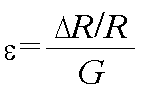
(ε:변형률, ΔR/R:저항값의 변화율, G: 변형률탐지부의 게이지 상수)(ε: strain rate, ΔR / R: change rate of resistance value, G: gauge constant of strain detector)
위치검출부(220')는 변형률검출부(210')에 의하여 검출된 변형률에 기초하여 누름힘(F)이 인가된 작용위치를 검출한다. 본 실시예의 경우도, 누름힘(F)의 작용위치는 터치입력구조(100')의 상층(110')에 미리 형성된 가상의 좌표계로 표현가능하며, 이러한 가상의 좌표계는 직교좌표계임이 바람직하다.The
위치검출부(220')의 작용위치 검출은 이하의 검출방법에서 설명할 연산을 수행함으로써 가능하다. 또한, 위치검출부(220')는 이러한 연산을 사전에 미리하여 그 결과를 룩업테이블 등의 형태로 데이터화하여 미리 저장함으로써, 누름힘(F)이 인가된 경우 신속하게 작용위치를 검출가능하도록 구성할 수 있다.The operation position detection of the position detection unit 220 'can be performed by performing an operation which will be described in the following detection method. In addition, the position detecting unit 220 'can preliminarily perform such a calculation and store the result in a form of a look-up table or the like in advance so that the operation position can be detected quickly when the pressing force F is applied. Can be.
세기검출부(230')는 앞서 설명한 제1실시예의 경우와 마찬가지인바, 앞선 기재로 갈음한다.The
<< 누름힘의Pressing 세기 및 작용위치 검출방법> Strength and Position Detection Method>
이하, 첨부된 도면을 참고하여, 본 발명에 따른 누름힘(F)의 세기 및 작용위 치 검출방법에 대하여 살펴본다.Hereinafter, with reference to the accompanying drawings, looks at the strength of the pressing force (F) and the operation position detection method according to the present invention.
(제1실시예)(Embodiment 1)
도 8은 본 발명에 누름힘(F)의 세기 및 작용위치 검출방법의 제1실시예에 따른 흐름도이다. 본 실시예는 앞서 설명한 제1실시예의 터치입력장치를 이용하는 것으로, 상층(110)과 하층(130)의 간격변화에 기초하여 누름힘(F)의 세기 및 작용위치를 검출하는 방법에 관한 것이다.8 is a flow chart according to the first embodiment of the method for detecting the strength and acting position of the pressing force (F) in the present invention. The present embodiment uses the touch input device of the first embodiment described above, and relates to a method of detecting the strength and the acting position of the pressing force F based on the change in the distance between the
먼저, 터치입력구조(100)의 상층(110)에 포인팅 오브젝트에 의한 누름힘(F)이 인가되면, 상층(110)은 누름힘(F)에 의하여 변형된다(S100). 상층(110)의 변형은 도 2에 도시된 바와 같다.First, when the pressing force F by the pointing object is applied to the
상층(110)이 변형되면서 상층(110)과 하층(130) 사이의 간격이 변화하고, 간격변화에 의하여 상층(110)과 하층(130)의 일면에 마주보도록 형성된 간격탐지부(140), 즉 전극의 정전용량값이 변한다. 이때, 검출부(200)는 정전용량값의 변화에 기초하여 상층(110)과 하층(130) 사이의 간격변화를 검출한다(S200).As the
이 후, 간격변화에 기초하여 누름힘(F)의 작용위치와 세기를 검출한다(S300). 누름힘(F)의 작용위치와 세기검출단계는 이하 도 9를 참고하여 설명한다. 도 9는 상층(110)의 임의의 지점에 누름힘(F)이 인가된 경우를 상층(110)에 미리 형성된 가상의 좌표계로 나타낸 상태도이다. 누름힘(F)이 인가되면, 검출부(200)는 간격변화와 누름힘(F)의 작용위치 및 세기에 관한 관계식을 설정한다(S310). 누름힘(F)의 작용위치(ax,ay)와 간격변화(δ1,δ2,…,δi,…,δn)의 관계식 은 하기의 [수학식 2]와 같다. 이때 누름힘(F)의 작용위치는 터치입력구조(100)상에 미리 형성된 가상의 좌표계(예, 직교 좌표계)로 표현된다. 이때 가상의 좌표계의 원점은 임의의 지점으로 설정가능하다.Thereafter, the operating position and the intensity of the pressing force (F) is detected based on the change in the interval (S300). The action position and the intensity detection step of the pressing force (F) will be described with reference to FIG. FIG. 9 is a state diagram illustrating a case where a pressing force F is applied to an arbitrary point of the
![]()
![]()
![]()
![]()
이 후, 이러한 관계식으로부터, 작용위치의 좌표를 획득하게 된다(S320). 작용위치의 좌표획득방법의 일예로, [수학식 3]과 같은 비례식을 사용할 수 있으며, 이러한 연산을 통해 검출되는 작용위치의 좌표는 검출부(200)의 위치검출부(220)에 의하여 획득될 수 있다. 또한, 이러한 연산을 통하여 미리 간격변화와 누름힘(F)의 작용위치의 관계를 룩업테이블 등으로 데이터화 한 후, 간격검출단계(S200)로부터 획득한 간격변화에 기초하여 데이터를 탐색함으로써 작용위치의 좌표를 획득할 수도 있다. 룩업데이블 등의 데이터로부터 작용위치의 좌표를 획득하는 경우, 작용위치를 검출하기 위한 연산과정이 생략되어 응답속도가 빨라지게 된다.Thereafter, the coordinates of the action position are obtained from the relational expression (S320). As an example of a method for acquiring the coordinates of the action position, a proportional expression such as [Equation 3] may be used, and the coordinates of the action position detected through this operation may be obtained by the
![]()
![]()
다음으로, 관계식 설정단계(S310)의 관계식과 작용위치 검출단계(S320)에서 획득된 작용위치 좌표에 기초하여, 누름힘(F)의 세기를 검출한다(S330). 누름힘(F)의 작용위치의 좌표(ax,ay)가 획득되고, 각 간격탐지부(140)의 위치좌표(xn,yn)는 이미 알고 있는 값이므로, 누름힘(F)의 세기를 획득할 수 있다.Next, the strength of the pressing force F is detected based on the relational expression of the relation setting step S310 and the coordinates of the acting position obtained in the acting position detecting step S320 (S330). Since the coordinates (a x , a y ) of the acting position of the pressing force (F) are obtained, and the position coordinates (x n , y n ) of each
본 발명에 따른 누름힘(F)의 작용위치 및 세기 검출방법은 처짐 곡선 기울기가 아주 작고 순수 굽힘에 의한 변형을 가정한 오일러 빔 이론에 기초할 수 있다. 이하에서는 그 일예로서, 터치입력구조(100)의 상층에 인가된 누름힘(F)의 작용위치를 x축과 y축의 좌표별로 획득하는 방법을 설명한다. 누름힘(F)의 작용위치와 세기를 검출하는 관계식은 터치입력구조(100)의 상층(110,110')과 하층(130,130')이 지지부(120,120')에 의하여 완전히 지지된 경우와 단순히 지지된 경우별로 달라지는바, 각 경우별로 설명한다.The position and intensity detection method of the pressing force F according to the present invention can be based on the Euler beam theory assuming that the deflection curve slope is very small and the deformation by pure bending is assumed. Hereinafter, as an example, a method of acquiring the operating position of the pressing force F applied to the upper layer of the
우선, 터치입력구조(100)가 단순히 지지된 경우를 살펴본다. 단순 지지의 경우는 경계조건이 각 가상의 좌표계에서의 변위변화가 '0'이 되는 것을 의미한다. 도 10은 간격탐지부(140)가 2개 구비된 경우로서, x축방향으로 터치입력구조(100)의 상층(110)의 변형에 따른 간격변화를 나타나기 위한 개략적인 개념도이다. 설명의 편의를 위하여 하층(130)은 생략하여 도시하였다. 좌측에 위치한 간격탐지부(140)의 간격변화를 δ1이라 하고, 우측에 구비된 간격탐지부(140)의 간격변화를 δ2라 한다. 상층의 x축 방향으로의 길이는 L이고, 간격탐지부(140: 전극) 각각의 위치는 x1,x2로 이미 알려진 값이다. 전극의 정전용량변화로부터 간격변화를 검출하고(S200), 앞서 기재한 [수학식 2]에 의하여 간격변화에 따른 누름힘(F)의 작용위치와 세기의 관계식을 설정하면(S310) 다음 [수학식 4]와 같다. [수학식 4]에서의 'E'는 상층의 탄성계수이고, 'I'는 관성모멘트이다.First, a case in which the


상기의 [수학식 4]의 δ1을 δ2로 나누면, 다음의 [수학식 5]와 같은 관계를 갖으며, 이로부터 누름힘(F)의 작용위치 좌표중 x축 성분인 ax를 구할 수 있다(S320). [수학식 5]에 나타난 바와 같이, δ1을 δ2로 나누면 누름힘(F)의 세기에 해당하는 미지수 "F"는 소거되므로 ax를 구할 수 있게 된다.Dividing δ 1 in Equation 4 by δ 2 has the same relationship as in Equation 5 below, and from this, a x , which is an x-axis component of the coordinates of the action position of the pressing force (F), is obtained. It may be (S320). As shown in [Equation 5], dividing δ 1 by δ 2 cancels the unknown “F” corresponding to the strength of the pressing force (F), so that a x can be obtained.

작용위치의 좌표인 ax를 구하면, 이 값을 [수학식 4]의 관계식 중 하나(예, δ1)에 대입하여, [수학식 6]과 같은 누름힘(F)의 세기를 구할 수 있다(S330).Obtaining a coordinate of a x of the action position, this value is substituted for one of the equations of [Equation 4] (for example, δ 1), can obtain the intensity of the pressing force (F) as shown in [Equation 6] (S330).

앞서 설명한 바와 마찬가지의 방법으로, y축 방향의 누름힘(F)의 작용위치 좌표와 누름힘(F)의 세기를 구할 수 있다. In the same manner as described above, the position coordinates of the pressing force F in the y-axis direction and the strength of the pressing force F can be obtained.
다음으로, 터치입력구조(100)가 완전히 지지된 경우를 살펴본다. 완전 지지의 경우는 경계조건이 각 가상의 좌표계에서의 변위변화가 '0'이 되고, 기울기 변화가 '0'이 되는 것을 의미한다. 도 11은 간격탐지부(140)가 2개 구비된 경우로서, x축방향으로 터치입력구조(110)의 상층(110)의 변형에 따른 간격변화를 개략적으로 도시한 것이다. 좌측에 위치한 간격탐지부(140)의 간격변화를 δ3이라 하고, 우측에 구비된 간격탐지부(140)의 간격변화를 δ4라 한다. 상층의 x축 방향으로의 길이는 L이고, 간격탐지부(140: 전극) 각각의 위치는 x3,x4로 이미 알려진 값이다. 전극의 정전용량변화로부터 간격변화를 검출하고(S200), [수학식 2]에 따른 누름힘(F)의 작용위치와 세기의 관계식을 설정하면(S310) 다음 [수학식 7]과 같다.Next, a case in which the


[수학식 7]에 기초하여 누름힘(F)의 작용위치 및 세기를 검출하는 방법(S320,S330)은, 앞서 언급한 [수학식 5]와 [수학식 6]의 경우와 마찬가지인바, 상세한 설명은 앞서 기재한 내용으로 갈음한다.The method (S320, S330) of detecting the acting position and the intensity of the pressing force (F) based on [Equation 7] is the same as in the case of [Equation 5] and [Equation 6] described above, The description is replaced with the above description.
(제2실시예)(Second Embodiment)
도 12는 본 발명에 누름힘(F)의 세기 및 작용위치 검출방법인 제2실시예에 따른 흐름도이다. 본 실시예는 앞서 설명한 제2실시예의 터치입력장치를 이용하여 상층(110')의 변형률로부터 누름힘(F)의 세기 및 작용위치를 검출하는 방법에 관한 것이다.12 is a flowchart according to the second embodiment of the present invention, which is a method of detecting the strength and the acting position of the pressing force (F). The present embodiment relates to a method of detecting the strength and the acting position of the pressing force F from the strain of the upper layer 110 'by using the touch input device of the second embodiment described above.
먼저, 터치입력구조(100')의 상층(110')에 포인팅 오브젝트에 의한 누름힘(F)이 인가되면, 상층(110')은 누름힘(F)에 의하여 변형된다(S100'). 상층(110')의 변형은 도 4에 도시된 바와 같다.First, when the pressing force F by the pointing object is applied to the upper layer 110 'of the touch input structure 100', the upper layer 110 'is deformed by the pressing force F (S100'). Deformation of the
상층(110')이 변형되면서 상층(110')의 일면에 형성된 변형률탐지부(140')의 저항값이 변한다. 이때, 검출부(200')는 저항값의 변화에 기초하여 상층의 변형률을 검출한다(S200'). As the upper layer 110 'is deformed, the resistance value of the strain detection unit 140' formed on one surface of the upper layer 110 'changes. At this time, the
이 후, 변형률에 기초하여 누름힘(F)의 작용위치와 세기를 검출한다(S300'). 누름힘(F)의 작용위치와 세기검출단계(S300')는 이하, 도 13을 참고하여 설명한다. 도 13은 상층(110')의 임의의 지점에 누름힘(F)이 인가된 경우를 상층(110')에 미리 형성된 가상의 좌표로 나타낸 상태도이다. 누름힘(F)이 인가되면, 검출부(200') 는 변형률과 누름힘(F)의 작용위치 및 세기에 관한 관계식을 설정한다(S310'). 누름힘(F)의 작용위치(ax,ay)와 변형률(ε1,ε2,…,εn)의 관계식은 하기의 [수학식 8]과 같다. 이때 누름힘(F)의 작용위치는 터치입력구조(100')상에 미리 형성된 가상의 좌표계(예, 직교 좌표계)로 표현된다. 이때 가상의 좌표계의 원점은 임의의 지점으로 설정가능하다.Thereafter, the acting position and the intensity of the pressing force F are detected based on the strain (S300 ′). The action position of the pressing force F and the intensity detection step S300 ′ will be described below with reference to FIG. 13. FIG. 13 is a state diagram showing virtual coordinates previously formed in the upper layer 110 'when the pressing force F is applied to an arbitrary point of the upper layer 110'. When the pressing force F is applied, the detection unit 200 'sets a relational expression regarding the strain and the acting position and the intensity of the pressing force F (S310'). The relationship between the action position (a x , a y ) of the pressing force (F) and the strain (ε 1 , ε 2 , ..., ε n ) is shown in Equation 8 below. At this time, the action position of the pressing force (F) is represented by a virtual coordinate system (eg, rectangular coordinate system) previously formed on the
![]()
![]()
![]()
![]()
이 후, 이러한 관계식으로부터 작용위치의 좌표를 획득하게 된다(S320'). 작용위치의 좌표획득방법의 일예로, [수학식 9]과 같은 비례식을 사용할 수 있으며, 또 다른 일예로, 이러한 연산을 통하여 미리 변형률과 누름힘(F)의 작용위치의 관계를 룩업테이블 등으로 데이터화 한 후, 변형률검출단계(S200')로부터 획득한 변형률에 기초하여 데이터를 탐색함으로써 작용위치의 좌표를 획득할 수도 있다. 이러한 연산을 통해 검출되는 작용위치의 좌표는 검출부(200')의 위치검출부(220')에서 담당할 수 있다. 룩업데이블 등의 데이터로부터 작용위치의 좌표를 획득하는 경우, 작용위치를 검출하기 위한 연산과정이 생략되어 응답속도가 빨라지게 된다.Thereafter, the coordinates of the action position are obtained from the relational expression (S320 '). As an example of the method of obtaining the coordinates of the acting position, a proportional expression such as [Equation 9] can be used. After the data is converted, the coordinates of the action position may be obtained by searching the data based on the strain obtained from the strain detection step S200 ′. The coordinates of the action position detected through this operation may be in charge of the
![]()
![]()
다음으로, 관계식 설정단계(S310')의 관계식과 작용위치 검출단계(S320')에서 획득된 작용위치 좌표에 기초하여, 누름힘(F)의 세기를 검출한다(S330'). 누름힘(F)의 작용위치의 좌표가 획득되고, 각 변형률탐지부(140')의 위치좌표(xn,yn)는 이미 알고 있는 값이므로, 누름힘(F)의 세기를 획득할 수 있다.Next, the strength of the pressing force F is detected based on the relational expression of the relation setting step S310 'and the operation position coordinate obtained in the acting position detecting step S320' (S330 '). Since the coordinates of the acting position of the pressing force F are obtained, and the position coordinates (x n , y n ) of each strain detection unit 140 'are already known values, the strength of the pressing force F can be obtained. have.
본 발명에 따른 누름힘(F)의 작용위치 및 세기 검출방법은 처짐 곡선 기울기가 아주 작고 순수 굽힘에 의한 변형을 가정한 오일러 빔 이론에 기초할 수 있다. 이하에서는, 터치입력구조(100')의 상층(110')에 인가된 누름힘(F)의 작용위치를 x축과 y축의 좌표별로 획득하는 방법을 설명한다. 누름힘(F)의 작용위치와 세기를 검출하는 관계식은 터치입력구조(100')의 상층(110')과 하층(130')이 지지부(120')에 의하여 완전히 지지된 경우와 단순 지지된 경우별로 달라지는바, 각 경우별로 설명한다.The position and intensity detection method of the pressing force F according to the present invention can be based on the Euler beam theory assuming that the deflection curve slope is very small and the deformation by pure bending is assumed. Hereinafter, a method of acquiring the action position of the pressing force F applied to the upper layer 110 'of the touch input structure 100' by the coordinates of the x-axis and the y-axis will be described. The relational expression for detecting the acting position and the strength of the pressing force F is simply supported when the upper layer 110 'and the lower layer 130' of the touch input structure 100 'are completely supported by the support 120'. It will vary from case to case, so it will be explained for each case.
우선, 터치입력구조(100')가 단순히 지지된 경우를 살펴본다. 단순 지지된 경우의 경계조건은 가상의 좌표계의 각 축의 변위 변화가 '0'이 되는 것을 의미한다. 도 14는 변형률탐지부(140')가 2개 구비된 경우로서, x축방향으로의 터치입력구조(100')의 상층(110')의 변형에 따른 변화를 개략적으로 도시한 개념도이다. 좌측에 위치한 변형률탐지부(140')의 변형률을 ε1이라 하고, 우측에 구비된 변형률탐 지부(140')의 변형률을 ε2라 한다. 상층의 x축 방향으로의 길이는 L이고, 변형률탐지부(140')의 각각의 위치는 x1,x2로 이미 알려진 값이다. 변형률탐지부(140')의 저항값 변화로부터 변형률을 검출하고(S200'), 변형률(ε)에 따른 누름힘(F)의 작용위치(ax,ay)와 세기(F)의 관계식을 설정하면(S310'), 다음 [수학식 10]과 같다.First, a case in which the touch input structure 100 'is simply supported will be described. The boundary condition in the case of simply supported means that the displacement change of each axis of the virtual coordinate system becomes '0'. FIG. 14 is a conceptual diagram schematically illustrating a change according to deformation of the upper layer 110 'of the touch input structure 100' in the x-axis direction when two strain detection units 140 'are provided. The strain of the

상기의 [수학식 10]의 ε1을 ε2로 나누면, 다음의 [수학식 11]과 같은 관계를 갖으며, 이로부터 누름힘(F)의 작용위치 좌표중 x축 성분인 ax를 구할 수 있다(S320'). [수학식 11]에 나타난 바와 같이, ε1을 ε2로 나누면 누름힘(F)의 세기에 해당하는 미지수 "F"는 소거되므로 ax를 구할 수 있게 된다.Dividing ε 1 in Equation 10 by ε 2 has the same relationship as in Equation 11 below, and from this, a x , which is an x-axis component of the coordinates of the action position of the pressing force (F), is obtained. It may be (S320 '). As shown in [Equation 11], dividing ε 1 by ε 2 eliminates the unknown “F” corresponding to the strength of the pressing force F, so that a x can be obtained.

ax를 구하면, 이 값을 [수학식 10]의 관계식 중 하나(예, ε1)에 대입하면, [수학식 12]과 같은 누름힘(F)의 세기를 구할 수 있다(S330').When a x is obtained, by substituting this value into one of the relational expressions of Equation 10 (eg, ε 1 ), the strength of the pressing force F as shown in Equation 12 can be obtained (S330 ').

앞서 설명한 바와 마찬가지의 방법으로, y축 방향의 누름힘(F)의 작용위치 좌표와 누름힘(F)의 세기를 구할 수 있다. In the same manner as described above, the position coordinates of the pressing force F in the y-axis direction and the strength of the pressing force F can be obtained.
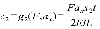
다음으로, 터치입력구조(100')가 완전히 지지된 경우를 살펴본다. 도 15는 변형률탐지부(140')가 2개 구비된 경우로서, x축방향으로 터치입력구조(100')의 상층(110')의 변형을 개략적으로 도시한 개념도이다. 좌측에 위치한 변형률탐지부(140')의 변형률을 ε3이라 하고, 우측에 구비된 변형률탐지부(140')의 변형률을 ε4라 한다. 상층의 x축 방향으로의 길이는 L이고, 변형률탐지부(140) 각각의 위치는 x3, x4로 이미 알려진 값이다. 변형률탐지부(140')의 저항값 변화로부터 변형률을 검출하고(S200'), 변형률에 따른 누름힘(F)의 작용위치와 세기의 관계식을 설정하면(S310'), 다음의 [수학식 13]과 같다. [수학식 13]에서의 'E'는 상층의 탄성계수이고, 'I'는 관성모멘트이며, 't'는 상층의 두께이다.Next, a case in which the


누름힘(F)의 작용위치 및 세기를 획득하는 단계(S320',S330')는 앞서 언급한 [수학식 11]과 [수학식 12]의 경우와 마찬가지의 방법으로 구할 수 있는바, 상세한 설명은 앞서 기재한 내용으로 갈음한다.Steps (S320 ', S330') to obtain the action position and the strength of the pressing force (F) can be obtained in the same manner as in the case of [Equation 11] and [Equation 12] described above, detailed description Is replaced with the above description.
<< 변형예Variant >>
누름힘(F)의 작용위치 및 세기를 검출하는 방법은 오일러 빔 이론 이외에도 티모센코(Timochenko) 빔 이론 또는 유한요소법(Finite Element Method)에 의할 수 있다. 수치해석인 유한요소법에 의할 경우, 터치입력장치가 사용되는 휴대폰 등의 기기와 유사한 경계조건과 다양한 형태를 갖는 터치스크린에 대한 누름힘(F)의 작용위치와 세기를 정확하게 검출할 수 있다.In addition to the Euler beam theory, the method of detecting the acting position and the intensity of the pressing force F may be based on the Timochenko beam theory or the finite element method. According to the finite element method, which is a numerical analysis, it is possible to accurately detect the action position and the intensity of the pressing force (F) for a touch screen having a variety of forms and boundary conditions similar to a device such as a mobile phone using a touch input device.
또한, 본 발명에 따른 터치입력구조와 터치입력장치는 도 5에 도시된 바와 같이 휴대폰(1)뿐만 아니라, 터치입력방식으로 동작 또는 위치명령을 입력하는 장치라면 어디에도 사용될 수 있음은 물론이다.In addition, the touch input structure and the touch input device according to the present invention may be used anywhere as well as the
비록 본 발명이 상기 언급된 바람직한 실시예와 관련되어 설명되어 졌지만, 발명의 요지와 범위로부터 벗어남이 없이 다양한 수정이나 변형을 하는 것이 가능하다. 따라서, 첨부된 특허청구범위는 본 발명의 요지에 속하는 한 이러한 수정이 나 변형을 포함할 것이다.Although the present invention has been described in connection with the above-mentioned preferred embodiments, it is possible to make various modifications or variations without departing from the spirit and scope of the invention. Accordingly, the appended claims will include such modifications and variations as long as they fall within the spirit of the invention.
본 명세서에서 첨부되는 다음의 도면들은 본 명세서의 바람직한 실시예를 예시하는 것이며, 발명의 상세한 설명과 함께 본 발명의 기술사상을 더욱 이해시키는 역할을 하는 것이므로, 본 발명은 그러한 도면에 기재된 사항에만 한정되어 해석되어서는 아니된다.The following drawings, which are attached in this specification, illustrate the preferred embodiments of the present specification, and together with the detailed description of the present invention, serve to further understand the technical spirit of the present invention. It should not be interpreted.
도 1은 본 발명에 따른 누름힘의 세기 및 작용위치 검출용 터치입력구조의 제1실시예에 따른 구성의 측단면도,1 is a side cross-sectional view of a configuration according to a first embodiment of a touch input structure for detecting the strength and action position of a pressing force according to the present invention;
도 2는 도 1의 터치입력구조에 누름힘이 인가된 경우의 측단면도,2 is a side cross-sectional view when a pressing force is applied to the touch input structure of FIG.
도 3은 본 발명에 따른 누름힘의 세기 및 작용위치 검출용 터치입력구조의 제2실시예에 따른 구성의 측단면도,Figure 3 is a side cross-sectional view of the configuration according to a second embodiment of the touch input structure for detecting the strength and action position of the pressing force according to the present invention;
도 4는 도 3의 터치입력구조에 누름힘이 인가된 경우의 측단면도,4 is a side cross-sectional view when a pressing force is applied to the touch input structure of FIG. 3;
도 5는 본 발명에 따른 터치입력구조를 이용한 터치입력장치가 휴대폰에 장착된 상태도,5 is a state in which a touch input device using a touch input structure according to the present invention is mounted on a mobile phone;
도 6은 본 발명에 따른 터치입력장치의 제1실시예에 따른 신호처리의 흐름에 따른 개략적인 블럭도,6 is a schematic block diagram of a signal processing flow according to a first embodiment of a touch input device according to the present invention;
도 7은 본 발명에 따른 터치입력장치의 제2실시예에 따른 신호처리의 흐름에 따른 개략적인 블럭도,7 is a schematic block diagram of a signal processing flow according to a second embodiment of a touch input device according to the present invention;
도 8은 본 발명에 따른 누름힘의 세기 및 작용위치 검출방법의 제1실시예에 따른 흐름도,8 is a flow chart according to the first embodiment of the method of detecting the strength of the pressing force and the action position according to the present invention;
도 9는 제1실시예에 따른 터치입력구조의 상층에 형성된 가상의 좌표계에 누 름힘의 작용위치와 간격탐지부의 위치를 도시한 상태도,9 is a state diagram showing an action position of a pressing force and a position of a gap detecting unit in a virtual coordinate system formed on an upper layer of a touch input structure according to the first embodiment;
도 10은 제1실시예에 따른 터치입력구조의 상층과 하층이 단순히 지지된 경우의 간격변화를 개략적으로 도시한 개념도,10 is a conceptual diagram schematically illustrating a change in spacing when an upper layer and a lower layer of the touch input structure according to the first embodiment are simply supported;
도 11은 제1실시예에 따른 터치입력구조의 상층과 하층이 완전히 지지된 경우의 간격변화를 개략적으로 도시한 개념도,11 is a conceptual diagram schematically illustrating a change in spacing when the upper and lower layers of the touch input structure according to the first embodiment are fully supported;
도 12는 본 발명에 따른 누름힘의 세기 및 작용위치 검출방법의 제2실시예에 따른 흐름도,12 is a flow chart according to a second embodiment of the method of detecting the strength of the pressing force and the action position according to the present invention;
도 13은 제2실시예에 따른 터치입력구조의 상층에 형성된 가상의 좌표계에 누름힘의 작용위치와 변형률탐지부의 위치를 도시한 상태도,FIG. 13 is a state diagram showing an action position of a pressing force and a position of a strain detector in a virtual coordinate system formed on an upper layer of a touch input structure according to a second embodiment;
도 14는 제2실시예에 따른 터치입력구조의 상층과 하층이 단순히 지지된 경우의 변형률을 개략적으로 도시한 개념도,14 is a conceptual diagram schematically illustrating a strain rate when the upper layer and the lower layer of the touch input structure according to the second embodiment are simply supported;
도 15는 제2실시예에 따른 터치입력구조의 상층과 하층이 완전히 지지된 경우의 변형률을 개략적으로 도시한 개념도이다.15 is a conceptual diagram schematically illustrating a strain rate when the upper layer and the lower layer of the touch input structure according to the second embodiment are fully supported.
<도면의 주요부분에 대한 부호의 설명><Description of the symbols for the main parts of the drawings>
1: 휴대폰1: cell phone
100, 100': 터치입력구조100, 100 ': touch input structure
110, 110': 상층110, 110 ': Upper floor
120. 120': 지지부120 '120': Support
130, 130': 하층130, 130 ': Lower floor
140; 간격탐지부140; Gap detector
140': 변형률탐지부140 ': strain detector
200,200': 검출부200,200 ': detector
210: 간격변화검출부210: gap change detection unit
210': 변형률검출부210 ': strain detection unit
220, 220': 위치검출부220, 220 ': position detector
230, 230': 세기검출부230, 230 ': Century Detector
Claims (32)

Priority Applications (2)
| Application Number | Priority Date | Filing Date | Title |
|---|---|---|---|
| KR1020080078532A KR100997107B1 (en) | 2008-08-11 | 2008-08-11 | Structure of touch input for acquiring location and intensity of force, apparatus therewith and acquiring method thereof |
| PCT/KR2008/005888 WO2010018889A1 (en) | 2008-08-11 | 2008-10-08 | Structure of touch input for acquiring location and intensity of force, apparatus therewith and acquiring method thereof |
Applications Claiming Priority (1)
| Application Number | Priority Date | Filing Date | Title |
|---|---|---|---|
| KR1020080078532A KR100997107B1 (en) | 2008-08-11 | 2008-08-11 | Structure of touch input for acquiring location and intensity of force, apparatus therewith and acquiring method thereof |
Publications (2)
| Publication Number | Publication Date |
|---|---|
| KR20100019808A KR20100019808A (en) | 2010-02-19 |
| KR100997107B1 true KR100997107B1 (en) | 2010-11-29 |
Family
ID=41669023
Family Applications (1)
| Application Number | Title | Priority Date | Filing Date |
|---|---|---|---|
| KR1020080078532A KR100997107B1 (en) | 2008-08-11 | 2008-08-11 | Structure of touch input for acquiring location and intensity of force, apparatus therewith and acquiring method thereof |
Country Status (2)
| Country | Link |
|---|---|
| KR (1) | KR100997107B1 (en) |
| WO (1) | WO2010018889A1 (en) |
Cited By (1)
| Publication number | Priority date | Publication date | Assignee | Title |
|---|---|---|---|---|
| KR20180079300A (en) * | 2016-11-23 | 2018-07-10 | 선전 구딕스 테크놀로지 컴퍼니, 리미티드 | Force measuring methods, devices and apparatus |
Families Citing this family (16)
| Publication number | Priority date | Publication date | Assignee | Title |
|---|---|---|---|---|
| US9024907B2 (en) | 2009-04-03 | 2015-05-05 | Synaptics Incorporated | Input device with capacitive force sensor and method for constructing the same |
| US9057653B2 (en) | 2010-05-11 | 2015-06-16 | Synaptics Incorporated | Input device with force sensing |
| US9297831B2 (en) | 2010-12-24 | 2016-03-29 | Graphene Square, Inc. | Touch sensor using graphene for simultaneously detecting a pressure and a position |
| US9557857B2 (en) | 2011-04-26 | 2017-01-31 | Synaptics Incorporated | Input device with force sensing and haptic response |
| EP2732361B1 (en) * | 2011-07-12 | 2018-05-23 | BlackBerry Limited | Electronic device and method of controlling a touch-sensitive display |
| US9748952B2 (en) | 2011-09-21 | 2017-08-29 | Synaptics Incorporated | Input device with integrated deformable electrode structure for force sensing |
| US9041418B2 (en) | 2011-10-25 | 2015-05-26 | Synaptics Incorporated | Input device with force sensing |
| JP5458196B2 (en) | 2012-03-02 | 2014-04-02 | 株式会社 資生堂 | Application operation evaluation apparatus, application operation evaluation method, and application operation evaluation program |
| KR102008736B1 (en) * | 2012-12-17 | 2019-08-09 | 엘지이노텍 주식회사 | Touch panel and method for driving the same |
| JP6243828B2 (en) | 2013-11-29 | 2017-12-06 | 株式会社 ハイディープHiDeep Inc. | Feedback method according to touch level and touch input device performing the same |
| KR101518786B1 (en) * | 2013-11-29 | 2015-05-15 | 주식회사 하이딥 | Feedback method of touch pressure level and device including touch screen performing the same |
| US10126861B2 (en) | 2015-05-08 | 2018-11-13 | Synaptics Incorporated | Force sensor substrate |
| KR102456154B1 (en) * | 2016-01-29 | 2022-10-19 | 삼성디스플레이 주식회사 | Sensor, touch sensor and display device |
| KR101664771B1 (en) * | 2016-04-29 | 2016-10-10 | 엘지이노텍 주식회사 | Touch panel and method for driving the same |
| US10452211B2 (en) | 2016-05-27 | 2019-10-22 | Synaptics Incorporated | Force sensor with uniform response in an axis |
| WO2018038367A1 (en) * | 2016-08-26 | 2018-03-01 | 주식회사 하이딥 | Touch input device including display panel having strain gauge, and method for manufacturing display panel having strain gauge |
Family Cites Families (3)
| Publication number | Priority date | Publication date | Assignee | Title |
|---|---|---|---|---|
| US20020149571A1 (en) * | 2001-04-13 | 2002-10-17 | Roberts Jerry B. | Method and apparatus for force-based touch input |
| US7183948B2 (en) * | 2001-04-13 | 2007-02-27 | 3M Innovative Properties Company | Tangential force control in a touch location device |
| US7148882B2 (en) * | 2003-05-16 | 2006-12-12 | 3M Innovatie Properties Company | Capacitor based force sensor |
-
2008
- 2008-08-11 KR KR1020080078532A patent/KR100997107B1/en not_active IP Right Cessation
- 2008-10-08 WO PCT/KR2008/005888 patent/WO2010018889A1/en active Application Filing
Cited By (3)
| Publication number | Priority date | Publication date | Assignee | Title |
|---|---|---|---|---|
| KR20180079300A (en) * | 2016-11-23 | 2018-07-10 | 선전 구딕스 테크놀로지 컴퍼니, 리미티드 | Force measuring methods, devices and apparatus |
| KR102050183B1 (en) * | 2016-11-23 | 2019-11-28 | 선전 구딕스 테크놀로지 컴퍼니, 리미티드 | Force measuring methods, devices and instruments |
| US10534469B2 (en) | 2016-11-23 | 2020-01-14 | Shenzhen GOODIX Technology Co., Ltd. | Force detection method, apparatus and device |
Also Published As
| Publication number | Publication date |
|---|---|
| WO2010018889A1 (en) | 2010-02-18 |
| KR20100019808A (en) | 2010-02-19 |
Similar Documents
| Publication | Publication Date | Title |
|---|---|---|
| KR100997107B1 (en) | Structure of touch input for acquiring location and intensity of force, apparatus therewith and acquiring method thereof | |
| CN105975137B (en) | Touch display panel and touch display device | |
| US10372261B2 (en) | Display device | |
| KR101597861B1 (en) | Sensor, display including a sensor, and method for using a sensor | |
| KR100969504B1 (en) | Touch inputting apparatus integral sensors | |
| US9965079B2 (en) | Pressure-sensitive touch screen and touch display screen and electronic device | |
| CN105929577B (en) | Display panel, display device and manufacturing method of display panel | |
| US20160378255A1 (en) | Self-Calibration of Force Sensors and Inertial Compensation | |
| US20130257744A1 (en) | Piezoelectric tactile interface | |
| US20130257759A1 (en) | Interleaved piezoelectric tactile interface | |
| US20090066673A1 (en) | Integrated force sensitive lens and software | |
| KR102605388B1 (en) | Bend sensing circuit, foldable display device and method for driving thereof | |
| WO2018043588A1 (en) | Capacitance type touch panel with built-in pressure sensor | |
| WO2013005861A1 (en) | Dual-function transducer for a touch panel | |
| CN101268435A (en) | Touch panel | |
| JP5898779B2 (en) | INPUT DEVICE AND METHOD FOR DETECTING MULTI-POINT LOAD USING THE INPUT DEVICE | |
| EP2738652B1 (en) | Built-in capacitive touch display screen, and touch point detection method and system therefor | |
| US10067625B2 (en) | Virtual deflection determination for force-sensing | |
| KR20130103254A (en) | The touch screen and key which can measure the coordinate and strength of touch position by deflection or viration sensors | |
| CN101231562A (en) | Force-sensing touch screen | |
| KR101124225B1 (en) | Touch inputting apparatus with integral sensors and method for fabricating thereof | |
| KR102400399B1 (en) | Flexible display device having touch sensor integarted bend sensor | |
| US20140085262A1 (en) | In-cell capacitive touch screen and touch contact detecting method and system thereof | |
| WO2017190399A1 (en) | Pressure sensing module, terminal, and image display method and apparatus | |
| JP2011076341A (en) | Touch panel measuring jig and measuring method |
Legal Events
| Date | Code | Title | Description |
|---|---|---|---|
| A201 | Request for examination | ||
| E902 | Notification of reason for refusal | ||
| E701 | Decision to grant or registration of patent right | ||
| GRNT | Written decision to grant | ||
| LAPS | Lapse due to unpaid annual fee |