KR100975722B1 - Method and system for transmitting/receiving data in a communication system - Google Patents
Method and system for transmitting/receiving data in a communication system Download PDFInfo
- Publication number
- KR100975722B1 KR100975722B1 KR1020070029213A KR20070029213A KR100975722B1 KR 100975722 B1 KR100975722 B1 KR 100975722B1 KR 1020070029213 A KR1020070029213 A KR 1020070029213A KR 20070029213 A KR20070029213 A KR 20070029213A KR 100975722 B1 KR100975722 B1 KR 100975722B1
- Authority
- KR
- South Korea
- Prior art keywords
- coding matrix
- transmission
- channel
- matrix
- receiver
- Prior art date
Links
Images
Classifications
-
- H—ELECTRICITY
- H04—ELECTRIC COMMUNICATION TECHNIQUE
- H04L—TRANSMISSION OF DIGITAL INFORMATION, e.g. TELEGRAPHIC COMMUNICATION
- H04L25/00—Baseband systems
- H04L25/02—Details ; arrangements for supplying electrical power along data transmission lines
- H04L25/03—Shaping networks in transmitter or receiver, e.g. adaptive shaping networks
- H04L25/03006—Arrangements for removing intersymbol interference
- H04L25/03821—Inter-carrier interference cancellation [ICI]
-
- H—ELECTRICITY
- H04—ELECTRIC COMMUNICATION TECHNIQUE
- H04L—TRANSMISSION OF DIGITAL INFORMATION, e.g. TELEGRAPHIC COMMUNICATION
- H04L1/00—Arrangements for detecting or preventing errors in the information received
- H04L1/004—Arrangements for detecting or preventing errors in the information received by using forward error control
- H04L1/0056—Systems characterized by the type of code used
-
- H—ELECTRICITY
- H04—ELECTRIC COMMUNICATION TECHNIQUE
- H04L—TRANSMISSION OF DIGITAL INFORMATION, e.g. TELEGRAPHIC COMMUNICATION
- H04L25/00—Baseband systems
- H04L25/02—Details ; arrangements for supplying electrical power along data transmission lines
- H04L25/03—Shaping networks in transmitter or receiver, e.g. adaptive shaping networks
- H04L25/03006—Arrangements for removing intersymbol interference
- H04L25/03343—Arrangements at the transmitter end
-
- H—ELECTRICITY
- H04—ELECTRIC COMMUNICATION TECHNIQUE
- H04L—TRANSMISSION OF DIGITAL INFORMATION, e.g. TELEGRAPHIC COMMUNICATION
- H04L27/00—Modulated-carrier systems
- H04L27/26—Systems using multi-frequency codes
- H04L27/2601—Multicarrier modulation systems
- H04L27/2626—Arrangements specific to the transmitter only
-
- H—ELECTRICITY
- H04—ELECTRIC COMMUNICATION TECHNIQUE
- H04L—TRANSMISSION OF DIGITAL INFORMATION, e.g. TELEGRAPHIC COMMUNICATION
- H04L27/00—Modulated-carrier systems
- H04L27/26—Systems using multi-frequency codes
- H04L27/2601—Multicarrier modulation systems
- H04L27/2647—Arrangements specific to the receiver only
Landscapes
- Engineering & Computer Science (AREA)
- Computer Networks & Wireless Communication (AREA)
- Signal Processing (AREA)
- Power Engineering (AREA)
- Radio Transmission System (AREA)
Abstract
본 발명은 통신 시스템에서 송신기가 데이터를 송신하는 방법에 있어서, 송신 코딩 행렬의 부호율에 상응하게 송신 신호들을 미리 지정된 개수씩 묶는 과정과, 상기 미리 지정된 개수씩 묶인 송신 신호들에 반송파간 간섭을 최소화하기 위한 상기 송신 코딩 행렬을 각각 곱하는 과정과, 상기 송신 코딩 행렬이 곱해진 송신 신호들을 수신기로 송신하는 과정을 포함하며, 상기 송신 코딩 행렬은 상기 송신기와 상기 수신기 간에 형성된 채널이 시변 레일리 채널일 경우, 채널 용량 하한을 최대화하도록 구성되고, 상기 채널 용량 하한은 상기 수신기가 수신한 간섭 및 잡음의 공분산을 사용하여 계산되고, 상기 공분산은 상기 송신 코딩 행렬과, 상기 송신 코딩 행렬의 허미션(Hermition) 행렬로 표현되는 상기 수신기의 수신 코딩 행렬을 사용하여 계산됨을 특징으로 한다.

간섭, ICI, MIMO, 코딩 행렬, 채널 용량, 부호율, 간섭 제거
The present invention provides a method for transmitting data by a transmitter in a communication system, the method comprising: a step of grouping transmission signals by a predetermined number corresponding to a code rate of a transmission coding matrix, and intercarrier interference on the transmission signals that are bundled by the predetermined number; Multiplying each of the transmission coding matrices for minimization and transmitting the transmission signals multiplied by the transmission coding matrix to a receiver, wherein the channel formed between the transmitter and the receiver is a time-varying Rayleigh channel. The channel capacity lower limit is calculated using the covariance of the interference and noise received by the receiver, the covariance being the transmittance of the transmission coding matrix and the transmission coding matrix. Computed using the receiver coding matrix of the receiver, It shall be.
Interference, ICI, MIMO, coding matrix, channel capacity, code rate, interference cancellation
Description
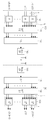
도 1은 본 발명의 실시예에 따른 통신 시스템의 송수신기 구조를 개략적으로 도시한 도면.1 is a schematic diagram illustrating a transceiver structure of a communication system according to an embodiment of the present invention.
도 2는 본 발명의 실시예에 따른 통신 시스템에서 채널 용량 하한을 도시한 도면.2 illustrates a lower channel capacity limit in a communication system according to an embodiment of the present invention.
도 3은 본 발명의 실시예에 따른 통신 시스템에서 채널 부호화를 수행한 경우의 BER을 도시한 도면.3 is a diagram illustrating BER when channel coding is performed in a communication system according to an embodiment of the present invention.
도 4는 본 발명의 실시예에 따른 통신 시스템에서 채널 부호화를 수행하지 않을 경우의 BER을 도시한 도면.4 is a diagram illustrating BER when no channel encoding is performed in a communication system according to an embodiment of the present invention.
도 5는 본 발명의 실시예에 따른 통신 시스템에서 채널 용량 하한을 도시한 도면.5 illustrates a lower channel capacity limit in a communication system according to an embodiment of the present invention.
본 발명은 통신 시스템에 관한 것으로, 특히 다중 반송파(multicarrier)를 이용한 통신 시스템에서 반송파간 간섭(ICI: Intercarrier Interference, 이하 'ICI'라 칭하기로 함)을 최소화하기 위한 데이터 송수신 방법 및 시스템에 관한 것이다.The present invention relates to a communication system, and more particularly, to a method and system for transmitting and receiving data for minimizing intercarrier interference (ICI) in a communication system using a multicarrier. .
통신에서 가장 근본적인 문제는 채널(channel)을 통하여 얼마나 효율적이고 신뢰성 있게(reliably) 데이터(data)를 전송할 수 있느냐 하는 것이다. 최근에 활발하게 연구되고 있는 차세대 멀티미디어 통신 시스템에서는 초기의 음성 위주의 서비스를 벗어나 영상, 무선 데이터 등의 다양한 정보를 처리하고 전송할 수 있는 고속 통신 시스템이 요구됨에 따라 시스템에 적절한 채널 부호화 방식을 사용하여 시스템의 효율을 높이는 것이 필수적이다.The most fundamental problem in communication is how efficiently and reliably data can be transmitted over a channel. In the next generation multimedia communication system, which is being actively researched recently, a high-speed communication system capable of processing and transmitting various information such as video and wireless data beyond the initial voice-oriented service is required. It is essential to increase the efficiency of the system.
그런데, 통신 시스템에 존재하는 무선 채널 환경은 유선 채널 환경과는 달리 다중 경로 간섭(multipath interference)과, 쉐도잉(shadowing)과, 전파 감쇠와, 시변 잡음과, 간섭 및 페이딩(fading) 등과 같은 여러 요인들로 인해 불가피한 오류가 발생하여 정보의 손실이 발생한다. 이러한 정보의 손실은 실제 송신 신호에 심한 왜곡을 발생시켜 통신 시스템의 전체 성능을 저하시키는 요인으로 작용하게 된다. 일반적으로 이러한 정보의 손실을 감소시키기 위해 채널의 성격에 따라 다양한 에러 제어 기법(error-control technique)을 이용하여 시스템의 신뢰도를 높이는데, 이러한 에러 제어 기법 중에 가장 기본적인 방법은 에러 정정 부호(error-correcting code)를 사용하는 것이다.However, unlike a wired channel environment, a wireless channel environment exists in a communication system such as multipath interference, shadowing, propagation attenuation, time-varying noise, interference, and fading. Factors cause unavoidable errors and loss of information. This loss of information causes severe distortion in the actual transmission signal, which reduces the overall performance of the communication system. In general, in order to reduce the loss of information, various error-control techniques are used to increase the reliability of the system according to the characteristics of the channel. The most basic of these error control techniques is an error-correcting code. correcting code.
한편, 차세대 통신 시스템에서는 고속의 다양한 서비스 품질(Quality of Service: 이하 'QoS' 칭하기로 함)을 가지는 서비스들을 사용자들에게 제공하기 위 한 활발한 연구가 진행되고 있다. 특히, 현재 차세대 통신 시스템에서는 무선 근거리 통신 네트워크(WLAN: Wireless Local Area Network, 이하 'WLAN'이라 칭하기로 함) 시스템 및 무선 도시 지역 네트워크(WMAN: Wireless Metropolitan Area Network, 이하 'WMAN'이라 칭하기로 함) 시스템과 같은 BWA 통신 시스템에 이동성(mobility)과 QoS를 보장하는 형태로 고속 서비스를 지원하도록 하는 연구가 활발하게 진행되고 있으며, 그 대표적인 통신 시스템이 IEEE(Institute of Electrical and Electronics Engineers) 802.16a/d 통신 시스템 및 IEEE 802.16e 통신 시스템이다.On the other hand, in the next generation communication systems, active researches are being conducted to provide users with services having high speed and quality of service (hereinafter referred to as 'QoS'). In particular, in the current generation communication system, a wireless local area network (WLAN) system and a wireless metropolitan area network (WMAN) will be referred to as "WMAN". Researches are being actively conducted to support high-speed services in the form of guaranteeing mobility and QoS to BWA communication systems such as systems, and the representative communication systems are IEEE (Institute of Electrical and Electronics Engineers) 802.16a / d communication system and IEEE 802.16e communication system.
상기 IEEE 802.16a/d 통신 시스템 및 IEEE 802.16e 통신 시스템은 상기 무선 MAN 시스템의 물리 채널(physical channel)에 광대역(broadband) 전송 네트워크를 지원하기 위해 직교 주파수 분할 다중(OFDM: Orthogonal Frequency Division Multiplexing, 이하 'OFDM'이라 칭하기로 한다)/직교 주파수 분할 다중 접속(OFDMA: Orthogonal Frequency Division Multiple Access, 이하 'OFDMA'이라 칭하기로 함) 방식을 적용한 통신 시스템(이하 'OFDM/OFDMA 통신 시스템'이라 칭하기로 함)이다. 상기 IEEE 802.16a/d 통신 시스템은 현재 가입자 단말기(SS: Subscriber Station, 이하 'SS'라 칭하기로 함)가 고정된 상태, 즉 SS의 이동성을 전혀 고려하지 않은 상태 및 단일 셀 구조만을 고려하고 있는 시스템이다. 이와는 달리 IEEE 802.16e 통신 시스템은 상기 IEEE 802.16a 통신 시스템에 SS의 이동성을 고려하는 시스템이며, 상기 이동성을 가지는 SS를 이동 단말기(MS: Mobile Station, 이하 'MS'라 칭하기로 함)이라고 칭하기로 한다.The IEEE 802.16a / d communication system and the IEEE 802.16e communication system are orthogonal frequency division multiplexing (OFDM) for supporting a broadband transmission network on a physical channel of the wireless MAN system. A communication system employing an Orthogonal Frequency Division Multiple Access (OFDMA) method (hereinafter, referred to as an 'OFDM / OFDMA communication system'). )to be. The IEEE 802.16a / d communication system currently considers only a single cell structure and a state in which a subscriber station (SS) (hereinafter referred to as SS) is fixed, i.e., does not consider SS mobility at all. System. In contrast, the IEEE 802.16e communication system is a system that considers the mobility of the SS in the IEEE 802.16a communication system, and the SS having the mobility is referred to as a mobile terminal (MS). do.
이러한 OFDM/OFDMA 통신 시스템에서 발생하는 ICI를 제거하기 위해 다양한 방안들, 예컨대 주파수 또는 시간 영역 등화를 이용하는 방안, 부호율을 이용한 ICI 제거 방안, 주파수 영역 부분 응답 부호화 방안이 제안되었다. 상기 주파수 또는 시간 영역 등화를 이용하는 방안은 최소평균자승오류(MMSE: Minimum Mean Square Error, 이하 'MMSE'라 칭하기로 함), 제로-포싱(ZF: Zero-Forcing, 이하 'ZF'라 칭하기로 함), 결정 피드백 등화기(DFE: Decision Feedback Equalizer, 이하 'DFE'라 칭하기로 함)를 이용하여 ICI를 제거하는 가장 일반적인 방안으로서 수신기에서 ICI를 추정한 후, 상기 추정한 ICI를 고려하여 등화를 수행한다. 그에 따라, 상기 주파수 또는 시간 영역 등화를 이용하는 방안은 채널의 변화 정도가 작은 경우에는 효과적으로 ICI를 제거할 수 있으나 채널의 변화 정도가 클 경우 등화를 위한 수신기의 복잡도가 증가하는 문제점이 있다.In order to remove the ICI generated in the OFDM / OFDMA communication system, various schemes, such as using frequency or time domain equalization, an ICI cancellation scheme using a code rate, and a frequency domain partial response encoding scheme, have been proposed. The scheme using frequency or time domain equalization is referred to as a minimum mean square error (MMSE), or zero-forcing (ZF). ), The most common method of removing ICI using a Decision Feedback Equalizer (DFE) (hereinafter, referred to as 'DFE'). After estimating the ICI at the receiver, the equalization is considered in consideration of the estimated ICI. To perform. Accordingly, the scheme using the frequency or time domain equalization can effectively remove the ICI when the degree of change of the channel is small, but increases the complexity of the receiver for equalization when the degree of change of the channel is large.
그리고, 부호율을 이용한 ICI 제거 방안, 예컨대 임의의 1/k(k≥2) 부호율을 이용한 ICI 제거 방안은, 주파수 영역에서 하나의 데이터 심볼(data symbol)을 미리 정의된 가중치 계수(weighting coefficients)들을 곱하여 한 그룹(group)의 부반송파로 매핑(mapping)하거나, 한 그룹의 부반송파 중 하나의 부반송파만 사용하되 시간 영역에서 윈도윙을 수행한다. 그에 따라, 상기 부호율을 이용한 ICI 제거 방안은, 신호 처리를 통해 수신기에서는 ICI가 상쇄된 형태의 수신 신호를 확인할 수 있으며, 또한 상기 수신기가 송신기와 동일한 가중치 계수를 사용하여 주파수 영역에서 한 그룹내의 여러 부반송파 수신 신호를 결합하거나, 수신기 시간 영역에서 윈도윙을 수행한 후 한 그룹 내 부반송파 수신 신호 중 하나의 수신 신호만을 이용하여 ICI를 더욱 상쇄시킬 수 있다. 이러한 부호율을 이용한 ICI 제거 방안은, 간단하게 ICI를 효율적으로 감소시킬 수 있고, 주파수 혹은 시간 영역 등화를 사용하는 방안보다 수신기 구조가 간단하지만 부호율에 상응하여 스펙트럼 효율(spectral efficiency)이 1/k배로 감소하는 문제점이 있다.In addition, an ICI removal method using a code rate, for example, an ICI removal method using an arbitrary 1 / k (k≥2) code rate, may include one data symbol in a frequency domain, and define predefined weighting coefficients. ) By multiplying) and mapping to a group of subcarriers, or using only one subcarrier of a group of subcarriers but performing windowing in the time domain. Accordingly, in the ICI cancellation method using the code rate, the receiver can identify the received signal having the ICI canceled form through signal processing, and the receiver uses the same weighting factor as that of the transmitter in a group in the frequency domain. After combining several subcarrier reception signals or performing windowing in the receiver time domain, ICI can be further canceled using only one reception signal among subcarrier reception signals in a group. The ICI cancellation scheme using this code rate can reduce the ICI simply and efficiently, and the receiver structure is simpler than the scheme using frequency or time domain equalization, but the spectral efficiency is 1 / corresponding to the code rate. There is a problem of decreasing by k times.
아울러, 주파수 영역 부분 응답 부호화 방안은, 수신기의 역고속 퓨리에 변환(IFFT: Inverse Fast Fourier Transform, 이하 'IFFT'라 칭하기로 함) 모듈로 입력되는 전송 신호들의 ICI를 제거하기 위해 단일 반송파 시스템에서 심볼간 간섭을 억제하기 위해 사용하던 부분 응답 코딩(PRC: Partial Response Coding, 이하 'PRC'라 칭하기로 함)을 수행한다. 그에 따라, 상기 주파수 영역 부분 응답 부호화 방안은 부호화를 수행한 후의 반송파대 간섭율(CIR: Carrier-to-Interference Ratio, 이하 'CIR'이라 칭하기로 함)이 부호화 이전의 CIR보다 커져 ICI가 효과적으로 제거된다. 이러한 주파수 영역 부분 응답 부호화 방안은 주파수 대역 효율을 감소시키지 않지만, ICI 제거 효과가 작으며 신호 검파를 위해 수신기가 최대 로그우도 시퀀스 추정기(MLSE: Maximum-Likelihood Sequence Estimator, 이하 'MLSE'라 칭하기로 함)를 사용하므로 수신기의 복잡도가 증가하는 문제점이 있다.In addition, the frequency domain partial response coding scheme is a symbol in a single carrier system to remove the ICI of the transmission signals input to the Inverse Fast Fourier Transform (IFFT) module of the receiver. Partial response coding (PRC), which is used to suppress inter-interference, is referred to as 'PRC'. Accordingly, in the frequency domain partial response coding scheme, the carrier-to-interference ratio (CIR: Carrier-to-Interference Ratio (CIR)) after encoding is larger than the CIR before encoding, thereby effectively removing ICI. do. Although the frequency domain partial response coding scheme does not reduce the frequency band efficiency, the ICI cancellation effect is small and the receiver will call the maximum log likelihood sequence estimator (MLSE) for signal detection. ), The complexity of the receiver increases.
따라서, 전술한 바와 같은 문제점들, 즉 수신기의 복잡도를 감소시키고 시스템의 성능을 향상시키며 ICI를 최소화하는 데이터 송수신 방안이 필요하다.Accordingly, there is a need for a data transmission / reception scheme for reducing the complexity of the receiver, improving system performance, and minimizing ICI.
따라서, 본 발명의 목적은 통신 시스템에서 데이터 송수신 방법 및 시스템을 제공함에 있다.Accordingly, an object of the present invention is to provide a method and system for transmitting and receiving data in a communication system.
본 발명의 다른 목적은 통신 시스템에서 ICI를 최소화하는 데이터 송수신 방법 및 시스템을 제공함에 있다.Another object of the present invention is to provide a data transmission / reception method and system for minimizing ICI in a communication system.
본 발명에서 제안하는 방법은; 통신 시스템에서 송신기가 데이터를 송신하는 방법에 있어서, 송신 코딩 행렬의 부호율에 상응하게 송신 신호들을 미리 지정된 개수씩 묶는 과정과, 상기 미리 지정된 개수씩 묶인 송신 신호들에 반송파간 간섭을 최소화하기 위한 상기 송신 코딩 행렬을 각각 곱하는 과정과, 상기 송신 코딩 행렬이 곱해진 송신 신호들을 수신기로 송신하는 과정을 포함하며, 상기 송신 코딩 행렬은 상기 송신기와 상기 수신기 간에 형성된 채널이 시변 레일리 채널일 경우, 채널 용량 하한을 최대화하도록 구성되고, 상기 채널 용량 하한은 상기 수신기가 수신한 간섭 및 잡음의 공분산을 사용하여 계산되고, 상기 공분산은 상기 송신 코딩 행렬과, 상기 송신 코딩 행렬의 허미션(Hermition) 행렬로 표현되는 상기 수신기의 수신 코딩 행렬을 사용하여 계산됨을 특징으로 한다.The method proposed in the present invention; A method for transmitting data by a transmitter in a communication system, the method comprising: binding a predetermined number of transmission signals according to a code rate of a transmission coding matrix, and minimizing inter-carrier interference with the predetermined number of transmission signals. Multiplying the transmission coding matrix, and transmitting the transmission signals multiplied by the transmission coding matrix to a receiver, wherein the transmission coding matrix is a channel when the channel formed between the transmitter and the receiver is a time-varying Rayleigh channel. Configured to maximize a lower capacity limit, wherein the lower channel capacity is calculated using the covariance of the interference and noise received by the receiver, the covariance being determined by the transmission matrix and the Hermition matrix of the transmission coding matrix. It is calculated using the reception coding matrix of the receiver to be represented .
본 발명에서 제안하는 다른 방법은; 통신 시스템에서 수신기가 데이터를 수신하는 방법에 있어서, 송신기로부터 다수의 수신 신호들을 수신하는 과정과, 수신 코딩 행렬의 부호율에 상응하여 상기 수신 신호들을 미리 지정된 개수씩 묶는 과정과, 상기 미리 지정된 개수씩 묶인 수신 신호들에 반송파간 간섭을 최소화하기 위한 상기 수신 코딩 행렬을 각각 곱하는 과정과, 상기 수신 코딩 행렬이 곱해진 수신 신호들을 출력하는 과정을 포함하며, 상기 수신 코딩 행렬은, 상기 송신기와 상기 수신기 간에 형성된 채널이 시변 레일리 채널일 경우, 채널 용량 하한을 최대화하도록 상기 송신기의 송신 코딩 행렬의 허미션(Hermition) 행렬로 나타내어지고, 상기 채널 용량 하한은 상기 수신기가 수신한 간섭 및 잡음의 공분산을 사용하여 계산되고, 상기 공분산은 상기 송신 코딩 행렬과, 상기 송신 코딩 행렬의 허미션 행렬로 표현되는 상기 수신기의 수신 코딩 행렬을 사용하여 계산된다.Another method proposed by the present invention; A method for receiving data by a receiver in a communication system, the method comprising: receiving a plurality of received signals from a transmitter, grouping the received signals by a predetermined number corresponding to a code rate of a reception coding matrix, and the predetermined number Multiplying the received coding matrices by the received coding matrices for minimizing inter-carrier interference and outputting the received signals multiplied by the receiving coding matrix, wherein the receiving coding matrix comprises: the transmitter and the; If the channel formed between the receivers is a time-varying Rayleigh channel, it is represented by a Hermition matrix of the transmitter's transmission coding matrix to maximize the channel capacity lower limit, and the channel capacity lower limit represents the covariance of the interference and noise received by the receiver. Computed using the covariance, the transmit coding matrix and the transmit It is calculated using the received matrix code of the receiver is represented by the Hermitian matrix of the coding matrix.
본 발명에서 제안하는 시스템은; 통신 시스템에서 데이터 송수신 시스템에 있어서, 송신 코딩 행렬의 부호율에 상응하여 송신 신호들을 미리 지정된 개수씩 묶고, 상기 미리 지정된 개수씩 묶인 송신 신호들에 반송파간 간섭을 최소화하기 위한 상기 송신 코딩 행렬을 각각 곱한 후, 상기 송신 코딩 행렬이 곱해진 송신 신호들을 송신하는 송신기와, 상기 송신기로부터 다수의 수신 신호들을 수신하며, 수신 코딩 행렬의 부호율에 상응하여 상기 수신 신호들을 미리 지정된 개수씩 묶고, 상기 미리 지정된 개수씩 묶인 수신 신호들에 상기 반송파간 간섭을 최소화하기 위한 상기 수신 코딩 행렬을 각각 곱한 후, 상기 수신 코딩 행렬이 곱해진 수신 신호들을 출력하는 수신기를 포함하며, 상기 송신 코딩 행렬 및 상기 수신 코딩 행렬은, 상기 송신기와 상기 수신기 간에 형성된 채널이 시변 레일리 채널일 경우, 채널 용량 하한을 최대화하도록 구성되고, 상기 채널 용량 하한은 상기 수신기가 수신한 간섭 및 잡음의 공분산을 사용하여 계산되고, 상기 공분산은 상기 송신 코딩 행렬과, 상기 송신 코딩 행렬의 허미션((Hermition) 행렬로 표현되는 상기 수신 코딩 행렬을 사용하여 계산됨을 특징으로 한다.The system proposed in the present invention; In a data transmission / reception system in a communication system, a predetermined number of transmission signals are bundled according to a code rate of a transmission coding matrix, and the transmission coding matrix for minimizing intercarrier interference is transmitted to the predetermined number of transmission signals. After multiplying, the transmitter transmits the transmission signals multiplied by the transmission coding matrix, and receives a plurality of reception signals from the transmitter, bundles the reception signals by a predetermined number corresponding to the code rate of the reception coding matrix, And a receiver for multiplying the reception signals bound by a specified number by the reception coding matrix for minimizing the inter-carrier interference, and then outputting the reception signals multiplied by the reception coding matrix, wherein the transmission coding matrix and the reception coding are performed. The matrix is a time-varying channel formed between the transmitter and the receiver In the case of a single channel, the lower channel capacity limit is configured to maximize the channel capacity lower limit, wherein the lower channel capacity limit is calculated using the covariance of the interference and noise received by the receiver, and the covariance is calculated from the transmission coding matrix and the transmission coding matrix. It is characterized by using the received coding matrix represented by the mission matrix (Hermition).
이하, 본 발명에 따른 바람직한 실시예를 첨부한 도면을 참조하여 상세히 설명한다. 하기의 설명에서는 본 발명에 따른 동작을 이해하는데 필요한 부분만이 설명되며 그 이외 부분의 설명은 본 발명의 요지를 흩트리지 않도록 생략될 것이라는 것을 유의하여야 한다.Hereinafter, exemplary embodiments of the present invention will be described in detail with reference to the accompanying drawings. It should be noted that in the following description, only parts necessary for understanding the operation according to the present invention will be described, and descriptions of other parts will be omitted so as not to distract from the gist of the present invention.
본 발명은, 통신 시스템, 일예로 광대역 무선 접속(BWA: Broadband Wireless Access, 이하 'BWA'라 칭하기로 함) 통신 시스템인 IEEE(Institute of Electrical and Electronics Engineers) 802.16 통신 시스템에서 데이터 송수신 방법 및 시스템을 제안한다. 여기서, 후술할 본 발명의 실시예에서는, 설명의 편의상 상기 통신 시스템을 IEEE 802.16e 통신 시스템에서 직교 주파수 분할 다중(OFDM: Orthogonal Frequency Division Multiplexing, 이하 'OFDM'이라 칭하기로 함)/직교 주파수 분할 다중 접속(OFDMA: Orthogonal Frequency Division Multiple Access, 이하 'OFDMA'이라 칭하기로 함) 방식을 적용한 통신 시스템(이하 'OFDM/OFDMA 통신 시스템'이라 칭하기로 함)을 일예로 하여 설명하지만, 본 발명에서 제안하는 데이터 송수신 방법 및 시스템은 다른 통신 시스템들에도 적용될 수 있다.The present invention provides a method and system for transmitting and receiving data in an IEEE 802.16 communication system, which is a communication system, for example, a broadband wireless access (BWA) communication system. Suggest. Here, in the embodiment of the present invention to be described later, orthogonal frequency division multiplexing (OFDM) / orthogonal frequency division multiplexing (OFDM) in the IEEE 802.16e communication system for convenience of description. Although a communication system (hereinafter referred to as an "OFDM / OFDMA communication system") to which an access (OFDMA: Orthogonal Frequency Division Multiple Access (OFDMA)) scheme is applied is described as an example, the present invention proposes The data transmission / reception method and system may be applied to other communication systems.
또한, 본 발명은 통신 시스템에서 송신기, 예컨대 소정의 셀을 관장하는 기지국(BS: Base Station, 이하 'BS'라 칭하기로 함)과, 수신기, 예컨대 상기 소정의 셀 내에 존재하며 상기 BS로부터 통신 서비스를 제공받는 이동 단말기(MS: Mobile Station, 이하 'MS'라 칭하기로 함) 간의 데이터 송수신 방법 및 시스템을 제안한 다. 후술할 본 발명의 실시예에서는 OFDM/OFDMA 통신 시스템에서 송신기와 수신기간의 데이터 송수신시 발생하는 반송파간 간섭(ICI: Intercarrier Interference, 이하 'ICI'라 칭하기로 함)을 최소화하는 데이터 송수신 방법 및 시스템을 제안한다.The present invention also relates to a base station (BS: Base Station, hereinafter referred to as "BS") that manages a transmitter, for example, a predetermined cell in a communication system, and a receiver, for example, that resides in the predetermined cell and communicates with the BS from the BS. The present invention proposes a method and system for transmitting and receiving data between a mobile terminal (MS: Mobile Station, hereinafter referred to as 'MS'). In an embodiment of the present invention to be described later, a data transmission / reception method and system for minimizing Intercarrier Interference (ICI), which occurs during data transmission and reception between a transmitter and a receiver in an OFDM / OFDMA communication system Suggest.
아울러, 본 발명은 통신 시스템에서 부호율을 이용하여 ICI를 최소화하는 데이터 송수신 방법 및 시스템을 제안한다. 후술할 본 발명의 실시예에서는 임의의 부호율, 예컨대 t/k(t≤k) 부호율의 주파수 영역 ICI 제거 부호를 통해 ICI를 최소화하는 데이터 송수신 방법 및 시스템을 제안한다. 여기서, 본 발명의 실시예에 따른 ICI 제거 부호는 통신 시스템의 주파수 대역 효율을 향상시키며 수신기의 복잡도를 감소시키고, 시스템의 성능 및 채널 용량과 비트 에러율(BER: Bit Error Rate, 이하 'BER'이라 칭하기로 함)의 성능을 향상시킨다. 또한, 본 발명은 t×t 다중 입력 다중 출력(MIMO: Multi-Input Multi-Output, 이하 'MIMO'라 칭하기로 함) 방식의 통신 시스템(이하 'MIMO 통신 시스템'이라 칭하기로 함) 또는 단일 입력 단일 출력(SISO: Single-Input Single-Output, 이하 'SISO'라 칭하기로 함) 방식의 통신 시스템(이하 'SISO'라 칭하기로 함)에서 t/k 부호율의 주파수 영역 ICI 제거 부호를 통해 ICI를 최소화하기 위해 송신기가 송신 코딩 행렬을 이용하여 데이터를 송신하고, 수신기가 수신 코딩 행렬을 이용하여 상기 송신기로부터 데이터를 수신한다.In addition, the present invention proposes a data transmission / reception method and system for minimizing ICI using a code rate in a communication system. An embodiment of the present invention to be described below proposes a data transmission / reception method and system for minimizing ICI through a frequency domain ICI elimination code having an arbitrary code rate, for example, a t / k (t ≦ k) code rate. Here, the ICI elimination code according to the embodiment of the present invention improves the frequency band efficiency of the communication system, reduces the complexity of the receiver, and performs the system performance, channel capacity, and bit error rate (BER). To improve performance). In addition, the present invention is a t x t multi-input multiple output (MIMO: Multi-Output (hereinafter referred to as "MIMO") type communication system (hereinafter referred to as "MIMO communication system") or a single input In a communication system with a single output (SISO: Single-Input Single-Output, hereinafter referred to as 'SISO') (hereinafter referred to as 'SISO') ICI through the frequency domain ICI elimination code at t / k code rate In order to minimize the transmitter, the transmitter transmits data using a transmission coding matrix, and the receiver receives data from the transmitter using a reception coding matrix.
이때, 본 발명의 실시예에 따른 통신 시스템은 최적의 송신 코딩 행렬과 수신 코딩 행렬을 결정하고, 상기 통신 시스템의 송신기는 송신 신호를 소정의 개수, 예컨대 t개씩 묶어 상기 송신 코딩 행렬을 곱한 후, 역이산 퓨리에 변환(IDFT: Inverse Discrete Fourier Transform, 이하 'IDFT'라 칭하기로 함)하여 송신하고, 상기 통신 시스템의 수신기는 상기 송신기로부터 수신되는 신호를 이산 퓨리에 변환(DFT: Discrete Fourier Transform, 이하 'DFT'라 칭하기로 함)한 후, 소정의 개수, 예컨대 k개씩 묶어 상기 수신 코딩 행렬을 곱하여 상기 수신 코딩 행렬 별로 t개의 수신 신호를 출력한다. 여기서, 본 발명의 실시예에 따른 통신 시스템의 수신기는 최대 로그우도(ML: Maximum-Likelihood, 이하 'ML'이라 칭하기로 함) 또는 수직 블라스트(V-BLAST: Vertical Bell Labs Layered Space-Time, 이하 'V-BLAST'라 칭하기로 함)와 같은 검파기들 통해 송신 신호를 검파한다. 또한, 상기 t/k 부호율의 주파수 영역 ICI 제거 부호, 즉 송신 코딩 행렬과 수신 코딩 행렬은 간섭이 존재하는 t×t MIMO 통신 시스템의 채널 용량 하한을 산출한 후, 상기 산출한 채널 용량 하한을 최대화하는 행렬로 결정된다. 그러면 여기서, 도 1을 참조하여 본 발명의 실시예에 따른 통신 시스템의 송수신기 구조에 대해 설명하기로 한다.In this case, the communication system according to an embodiment of the present invention determines an optimal transmission coding matrix and a reception coding matrix, and the transmitter of the communication system multiplies the transmission coding matrix by tying a predetermined number, for example, t, by Inverse Discrete Fourier Transform (IDFT: hereinafter referred to as 'IDFT') for transmission, and the receiver of the communication system transmits a Discrete Fourier Transform (DFT) signal received from the transmitter. DFT '), and a predetermined number, for example, k, are multiplied and multiplied by the reception coding matrix to output t received signals for each reception coding matrix. Here, the receiver of the communication system according to an embodiment of the present invention may be a maximum log likelihood (ML: Maximum-Likelihood, hereinafter referred to as 'ML') or vertical blast (V-BLAST: Vertical Bell Labs Layered Space-Time, hereinafter). Detects the transmission signal through detectors such as 'V-BLAST'. In addition, the frequency domain ICI elimination code of the t / k code rate, that is, the transmission coding matrix and the reception coding matrix calculates the channel capacity lower limit of the t × t MIMO communication system where interference exists, and then calculates the channel capacity lower limit. Determined by the matrix to maximize. Next, a transceiver structure of a communication system according to an embodiment of the present invention will be described with reference to FIG. 1.
도 1은 본 발명의 실시예에 따른 통신 시스템의 송수신기 구조를 개략적으로 도시한 도면이다.1 is a diagram schematically illustrating a transceiver structure of a communication system according to an embodiment of the present invention.
도 1을 참조하면, 송신기(100)는 송신하고자 하는 신호, 즉 송신기(100)로 입력되는 입력 신호(s)를 t개씩 묶어 송신 코딩 행렬(B)을 곱하여 송신 코딩 행렬(B) 별로 k개씩 출력하는 제1곱셈부(110)와, 상기 제1곱셈부(110)의 출력 신호를 IDFT하는 IDFT부(120)와, 상기 IDFT된 병렬 형태의 신호를 직렬 형태의 신호로 변환하는 병렬/직렬 변환부(130), 및 순환 접두어(CP: Cyclic Prefix, 이하 'CP'라 칭하기로 함)를 삽입한 후 송신 안테나를 통해 신호를 송신하는 CP 삽입부(140)를 포함한다. 그리고, 수신기(150)는 수신 안테나를 통해 송신기(100)로부터 전송되는 신호에 포함된 CP를 제거하는 CP 제거부(160)와, 상기 CP 제거부(160)로부터 전송되는 직렬 형태의 신호를 병렬 형태의 신호로 변환하는 직렬/병렬 변환부(170)와, 상기 직렬/병렬 변환부(203)로부터 전송되는 신호를 DFT하는 DFT부(180), 및 상기 DFT부(180)로부터 전송되는 신호를 k개씩 묶어 수신 코딩 행렬(GH)을 곱하여 상기 수신 코딩 행렬(GH) 별로 t개의 수신 신호(y)를 출력하는 제2곱셈부(190)를 포함한다.Referring to FIG. 1, the
여기서, 상기 송신기(100)의 제1곱셈부(110)는 상기 송신기(100)와 수신기(150)에 심볼의 서브캐리어 개수가 N일 경우, 다시 말해 상기 IDFT(120)의 크기가 N일 경우 N/k개의 제1곱셈기들을 포함하며, 상기 제1곱셈기들에는 송신하고자 하는 신호, 즉 입력 신호(s)가 t개씩 각각 입력되며, 상기 입력된 t개의 입력 신호(s)에 송신 코딩 행렬(B)이 곱해진 k개의 출력 신호를 IDFT부(120)로 각각 출력한다. 즉, 상기 제1곱셈기들은 t개의 입력 심볼들이 각각 입력되고, 상기 입력된 t개의 입력 심볼들에 송신 코딩 행렬개의 서브캐리어들을 IDFT부(120)로 각각 출력한다. 또한, 상기 수신기(150)의 제2곱셈부(190)는 전술한 바와 같이 상기 송신기(100)와 수신기(150)에 형성된 채널(H)의 서브캐리어 개수가 N일 경우, 다시 말해 상기 DFT(180)의 크기가 N일 경우 N/t개의 제2곱셈기들을 포함하며, 상기 제2곱셈기들에는 DFT(180)의 출력 신호가 k개씩 각각 입력되며, 상기 입력된 k개의 출력 신호에 수신 코딩 행렬(GH)이 곱해진 t개의 출력 신호를 각각 출력한다. 즉, 상기 제2곱셈기들은 k개의 서브캐리어들이 각각 입력되고, 상기 입력된 k개의 서브캐리어들에 수신 코딩 행렬(GH)을 곱하여 t개의 출력 심볼들을 출력한다. 여기서, 상기 송신 코딩 행렬(B)은 k×t 행렬이고 상기 수신 코딩 행렬GH)은 t×k 행렬이며, 이하에서는 본 발명의 실시예에 따른 통신 시스템에서 최적의 상기 k×t의 송신 코딩 행렬(B)과 t×k의 수신 코딩 행렬(GH)을 결정하는 과정에 대해 구체적으로 설명하기로 한다.Here, when the number of subcarriers of the symbol is N in the
우선, 상기 수신기(150)가 수신하는 수신 신호(y)는 하기 수학식 1과 같이 나타낼 수 있다.First, the reception signal y received by the
![]()
![]()
상기 수학식 1에서, ![]()
![]()
![]()
![]()
![]()
![]()
![]()
![]()
![]()
![]()
![]()
![]()
그러면, 상기 수신기(150)의 DFT부(180)의 DFT 행렬을 ![]()
![]()
![]()


![]()

![]()
![]()
![]()
![]()
![]()
![]()
![]()
![]()
이때, 통신 시스템에서 한 심볼 내에서 채널이 가변하면 ICI가 발생되며, 이러한 ICI는 채널 행렬 ![]()
![]()
![]()
![]()
![]()
![]()
![]()
![]()
![]()
![]()
![]()
![]()
![]()
![]()
![]()
![]()
![]()
![]()
![]()
![]()
![]()
![]()
![]()
![]()
![]()
![]()
![]()
![]()
![]()
![]()

상기 수학식 2에서 ![]()
![]()
![]()
![]()
상기 수학식 2에서 ![]()
![]()
![]()
![]()
![]()
![]()
![]()
![]()
우선, 상기 수학식 2에서 시스템의 채널 용량 하한을 산출하기 위해 다음과 같이 가정하기로 한다.First, in order to calculate the channel capacity lower limit of the system in
상기 송신기(100)가 송신하고자 하는 신호, 즉 입력 신호 ![]()
![]()
![]()
![]()
![]()
![]()
![]()
![]()
![]()
![]()
상기 수학식 4에서, ![]()
![]()
![]()
![]()
![]()
![]()
![]()
![]()
![]()
![]()
![]()
![]()
![]()
![]()
![]()
![]()

상기 수학식 5에서, ![]()
![]()
![]()
![]()
![]()
![]()
![]()
![]()

상기 수학식 6에서, ![]()
![]()
![]()
![]()
![]()
![]()
![]()
![]()
![]()
![]()
![]()
![]()

![]()
![]()

상기 수학식 9에서 m은 임의의 정수를 의미하고, 수학식 10에서 ![]()

![]()
![]()
![]()
그러면, 상기 송신 코딩 행렬(B)과 수신 코딩 행렬(GH)은 전술한 바와 같이 채널 용량 하한 ![]()
![]()
![]()
![]()
![]()
![]()
이때, 상기 송신 코딩 행렬(B)과 수신 코딩 행렬(GH) 은 시변 레일리 채널에 대해 상기 채널 용량 하한을 최대화하는 최적의 행렬을 결정하고, 상기 시변 레일리 채널 이외에 대해 채널의 자기상관 r(n)을 상이하게 정의하여 결정한다.In this case, the transmission coding matrix B and the reception coding matrix G H determine an optimal matrix for maximizing the channel capacity lower limit for the time-varying Rayleigh channel, and autocorrelation r (n) for the channel other than the time-varying Rayleigh channel. To be defined differently.
예를 들어, 도플러 주파수(Doppler frequency: fdTs)가 0.01에서 0.51까지 0.05 간격으로 변화할 때 Jakes의 모델을 이용하여 채널 H(0,0)을 독립적으로 생성하고, 자기상관 r(n)은 fdTs가 0.01에서 0.51까지 균일하게 변화할 경우의 J0(2π fdTsn/N)의 평균으로 가정한다. 여기서, Ts는 OFDM 심볼 시간을 나타내고, J0는 첫 번째 종류의 영차 Bessel 함수이다. 그러면, 상기 수학식 5에서 채널 행렬 ![]()
![]()

그러면 이하에서는 본 발명의 실시예에 따른 통신 시스템에 채널 용량 하한 및 BER 성능을 설명하기로 한다.Next, a channel capacity lower limit and a BER performance will be described in a communication system according to an embodiment of the present invention.
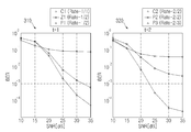
도 2는 본 발명의 실시예에 따른 통신 시스템에서 채널 용량 하한을 도시한 도면이다. 여기서, 도 2는 SNR이 25㏈일 경우 주파수 선택적 채널에서 채널 용량 하한을 도시한 도면이다.2 illustrates a lower channel capacity limit in a communication system according to an exemplary embodiment of the present invention. 2 is a diagram illustrating a channel capacity lower limit in a frequency selective channel when the SNR is 25 Hz.
도 2를 참조하면, t=1일 경우(210)의 시스템들, 예컨대 1/1 부호와 ICI 제거 부호를 적용하지 않은, 즉 B=G=1을 적용한 시스템1(C1), 본 발명에 따른 1/2 부호를 적용한 시스템2(P1), 1/2 부호와 B=G=[1, -1]T를 적용한 시스템3(Z1), 1/2 부호와 B=G=[0, ![]()
![]()
또한, t=3일 경우(230)와 t=4일 경우(240)의 시스템에서 3/3부호와 ICI 제거 부호를 적용하지 않은 시스템8(C3)과 4/4 부호와 ICI 제거 부호를 적용하지 않은 시스템11(C4)은 본 발명의 실시예에 따른 3/3 부호를 적용한 시스템9(P4), 3/4 부호를 적용한 시스템10(P5), 4/4 부호를 적용한 시스템12(P6), 4/5 부호를 적용한 시스템13(P7)보다 채널 용량 하한이 낮다. 따라서, 본 발명의 실시예에 따른 ICI 부호를 적용한 시스템은 ICI에 강인하게 된다.In addition, in case of t = 3 (230) and in case of t = 4 (240), the system 8 (C3) and the 4/4 code and the ICI remove code that do not apply the 3/3 code and the ICI remove code are applied. The non-system 11 (C4) is the system 9 (P4) applying the 3/3 code, the system 10 (P5) applying the 3/4 code, and the system 12 (P6) applying the 4/4 code according to the embodiment of the present invention. , Lower channel capacity lower than System 13 (P7) with 4/5 code. Therefore, the system applying the ICI code according to the embodiment of the present invention is robust to ICI.
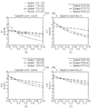
도 3은 본 발명의 실시예에 따른 통신 시스템에서 채널 부호화를 수행한 경우의 BER을 도시한 도면이다. 여기서, 도 3은 도플러 주파수(fdTs)가 0.2일 경우의 주파수 선택적 페이딩 채널에서 채널 부호화를 수행한 경우의 BER을 도시한 도면이다.3 is a diagram illustrating BER when channel coding is performed in a communication system according to an embodiment of the present invention. 3 is a diagram illustrating BER when channel coding is performed on a frequency selective fading channel when the Doppler frequency f d T s is 0.2.
도 3을 참조하면, t=1일 경우(310)의 시스템, 예컨대 1/1 부호와 ICI 제거 부호를 적용하지 않은, 즉 B=G=1을 적용한 시스템1(C1), 본 발명의 실시예에 따른 1/2 부호를 적용한 시스템2(P1), 1/2 부호와 B=G=[1, -1]T를 적용한 시스템3(Z1)과 t=2일 경우(320)의 시스템, 예컨대 2/2부호와 ICI 제거 부호를 적용하지 않은, 즉 B=G=I2를 적용한 시스템5(C2), 본 발명의 실시예에 따른 2/2 부호를 적용한 시스템6(P2), 본 발명의 실시예에 따른 2/3 부호를 적용한 시스템7(P3)에서 본 발명의 실시예에 따른 ICI 부호를 적용한 시스템들, 즉 시스템2(P1), 시스템6(P2), 시스템7(P3)은 ICI에 의한 성능 저하가 상기 ICI 부호를 적용하지 않은 시스템보다 작다.Referring to FIG. 3, a system in the case of t = 1 (310), for example, a system 1 (C1) without applying a 1/1 code and an ICI elimination code, that is, applying B = G = 1, is an embodiment of the present invention. System 2 (P1) applying 1/2 sign according to the system, system 3 (Z1) applying 1/2 sign and B = G = [1, -1] T and 320 when t = 2 (e.g., System 5 (C2) without 2/2 code and ICI elimination code, i.e., B = G = I 2 , system 6 (P2) with 2/2 code according to an embodiment of the present invention, In the system 7 (P3) applying the 2/3 code according to the embodiment, the systems applying the ICI code according to the embodiment of the present invention, that is, the system 2 (P1), the system 6 (P2), and the system 7 (P3) are the ICI. The performance degradation due to is smaller than that of the system without the ICI code.
도 4는 본 발명의 실시예에 따른 통신 시스템에서 채널 부호화를 수행하지 않을 경우의 BER을 도시한 도면이다. 여기서, 도 4는 도플러 주파수(fdTs)가 0.2일 경우의 주파수 선택적 페이딩 채널에서 채널 부호화를 수행하지 않을 경우의 BER을 도시한 도면이다.4 is a diagram illustrating a BER when no channel encoding is performed in a communication system according to an embodiment of the present invention. 4 is a diagram illustrating a BER when no channel coding is performed in a frequency selective fading channel when the Doppler frequency f d T s is 0.2.
도 4를 참조하면, t=1일 경우(410)의 시스템, 예컨대 1/1 부호와 ICI 제거 부호를 적용하지 않은, 즉 B=G=1을 적용한 시스템1(C1), 본 발명의 실시예에 따른 1/2 부호를 적용한 시스템2(P1), 1/2 부호와 B=G=[1, -1]T를 적용한 시스템3(Z1)과 t=2일 경우(420)의 시스템, 예컨대 2/2부호와 ICI 제거 부호를 적용하지 않은, 즉 B=G=I2를 적용한 시스템5(C2), 본 발명의 실시예에 따른 2/2 부호를 적용한 시스템6(P2), 본 발명의 실시예에 따른 2/3 부호를 적용한 시스템7(P3)에서 본 발명의 실시예에 따른 ICI 부호를 적용한 시스템들, 즉 시스템2(P1), 시스템6(P2), 시스템7(P3)은 ICI에 의한 성능 저하가 상기 ICI 부호를 적용하지 않은 시스템보다 작다.Referring to FIG. 4, a system 1 (C1) without applying a 1/1 code and an ICI elimination code, that is, applying B = G = 1, when t = 1 (410), an embodiment of the present invention. System 2 (P1) applying 1/2 sign according to the system, system 3 (Z1) applying 1/2 sign and B = G = [1, -1] T and the system when t = 2 (420), for example System 5 (C2) without 2/2 code and ICI elimination code, i.e., B = G = I 2 , system 6 (P2) with 2/2 code according to an embodiment of the present invention, In the system 7 (P3) applying the 2/3 code according to the embodiment, the systems applying the ICI code according to the embodiment of the present invention, that is, the system 2 (P1), the system 6 (P2), and the system 7 (P3) are the ICI. The performance degradation due to is smaller than that of the system without the ICI code.
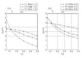
도 5는 본 발명의 실시예에 따른 통신 시스템에서 채널 용량 하한을 도시한 도면이다. 여기서, 도 5는 SNR이 25㏈일 경우 AWGN 채널에서 채널 용량 하한을 도시한 도면이다.5 illustrates a lower channel capacity limit in a communication system according to an exemplary embodiment of the present invention. 5 is a diagram illustrating a channel capacity lower limit in the AWGN channel when the SNR is 25 Hz.
도 5를 참조하면, t=1일 경우(510)의 단일 입력 단일 출력(SISO: Single-Input Single-Output, 이하 'SISO'라 칭하기로 함) 시스템, 예컨대 1/1 부호와 ICI 제거 부호를 적용하지 않은, 즉 B=G=1을 적용한 시스템1(C1), 1/2 부호를 적용한 시스템2(P1), 1/2 부호와 B=G=[1, -1]T를 적용한 시스템3(Z1)과 t=2일 경우(520)의 MIMO 시스템, 예컨대 2/2부호와 ICI 제거 부호를 적용하지 않은, 즉 B=G=I2를 적용한 시스템5(C2), 2/2 부호를 적용한 시스템6(P2), 2/3 부호를 적용한 시스템7(P3)에서 ICI 제거 부호를 적용하지 않은 시스템의 채널 용량 하한이 ICI 제거 부호를 적용한 시스템의 채널 용량보다 낮다. 따라서, 본 발명의 실시예에 따른 ICI 부호를 적용한 시스템은 ICI에 강인하게 된다.Referring to FIG. 5, when t = 1, a single input single output (SISO: Single-Input Single-Output, hereinafter referred to as 'SISO') system, such as a 1/1 sign and an ICI removal code, System 1 (C1) with no B = G = 1, System 2 (P1) with 1/2 sign,
한편, 본 발명의 상세한 설명에서는 구체적인 실시예에 관해 설명하였으나, 본 발명의 범위에서 벗어나지 않는 한도내에서 여러 가지 변형이 가능함은 물론이다. 그러므로 본 발명의 범위는 설명된 실시예에 국한되어 정해져서는 안되며 후술하는 특허청구의 범위뿐만 아니라 이 특허청구의 범위와 균등한 것들에 의해 정해져야 한다.Meanwhile, in the detailed description of the present invention, specific embodiments have been described, but various modifications are possible without departing from the scope of the present invention. Therefore, the scope of the present invention should not be limited to the described embodiments, but should be defined not only by the scope of the following claims, but also by the equivalents of the claims.
상술한 바와 같은 본 발명은, 송신 코딩 행렬과 수신 코딩 행렬을 이용하여 데이터를 송수신함으로써, ICI를 최소할 수 있다. 따라서, 본 발명은, ICI를 최소화함으로써 데이터 송수신 효율 및 시스템의 성능을 향상시키며, 시스템의 복잡도를 감소시킬 수 있다.As described above, the present invention can minimize ICI by transmitting and receiving data using a transmission coding matrix and a reception coding matrix. Accordingly, the present invention can improve data transmission and reception efficiency and system performance by minimizing ICI, and reduce system complexity.
Claims (27)
Priority Applications (2)
| Application Number | Priority Date | Filing Date | Title |
|---|---|---|---|
| KR1020070029213A KR100975722B1 (en) | 2007-03-26 | 2007-03-26 | Method and system for transmitting/receiving data in a communication system |
| US11/850,545 US8687675B2 (en) | 2007-03-26 | 2007-09-05 | Method and system for transmitting/receiving data in communication system |
Applications Claiming Priority (1)
| Application Number | Priority Date | Filing Date | Title |
|---|---|---|---|
| KR1020070029213A KR100975722B1 (en) | 2007-03-26 | 2007-03-26 | Method and system for transmitting/receiving data in a communication system |
Publications (2)
| Publication Number | Publication Date |
|---|---|
| KR20080087254A KR20080087254A (en) | 2008-10-01 |
| KR100975722B1 true KR100975722B1 (en) | 2010-08-12 |
Family
ID=39794297
Family Applications (1)
| Application Number | Title | Priority Date | Filing Date |
|---|---|---|---|
| KR1020070029213A KR100975722B1 (en) | 2007-03-26 | 2007-03-26 | Method and system for transmitting/receiving data in a communication system |
Country Status (2)
| Country | Link |
|---|---|
| US (1) | US8687675B2 (en) |
| KR (1) | KR100975722B1 (en) |
Families Citing this family (5)
| Publication number | Priority date | Publication date | Assignee | Title |
|---|---|---|---|---|
| EP2311210A4 (en) * | 2008-08-04 | 2015-05-20 | Nxp Bv | A radio channel model for ici cancellation in multi-carrier systems |
| CN102014440B (en) * | 2009-09-28 | 2015-05-06 | 电信科学技术研究院 | Method, device and system for inter-cell interference coordination (ICIC) |
| US8817834B2 (en) * | 2011-05-02 | 2014-08-26 | Maxlinear, Inc. | Method and system for I/Q mismatch calibration and compensation for wideband communication receivers |
| US10516498B1 (en) * | 2017-05-31 | 2019-12-24 | Quantenna Communications, Inc. | Wifi multi-user CPE and ICI mitigation |
| TWI759920B (en) * | 2020-10-22 | 2022-04-01 | 國立清華大學 | Power allocation method for non-orthogonal multiple access system and base station using the same |
Citations (3)
| Publication number | Priority date | Publication date | Assignee | Title |
|---|---|---|---|---|
| KR20020079489A (en) * | 2001-04-09 | 2002-10-19 | 니폰덴신뎅와 가부시키가이샤 | OFDM signal transmission system, OFDM signal transmission apparatus and OFDM signal receiver |
| KR20050066634A (en) * | 2003-12-26 | 2005-06-30 | 한국전자통신연구원 | System and method for equalization in ofdm |
| KR20070005776A (en) * | 2005-07-06 | 2007-01-10 | 삼성전자주식회사 | Mimo-based data transmission method |
Family Cites Families (15)
| Publication number | Priority date | Publication date | Assignee | Title |
|---|---|---|---|---|
| FI100150B (en) * | 1996-03-19 | 1997-09-30 | Nokia Telecommunications Oy | Reception method and receiver |
| US6631175B2 (en) * | 1998-04-03 | 2003-10-07 | Tellabs Operations, Inc. | Spectrally constrained impulse shortening filter for a discrete multi-tone receiver |
| US7099401B2 (en) * | 1999-12-15 | 2006-08-29 | Paradyne Corporation | Discrete multitone interleaver |
| US6834043B1 (en) * | 2000-07-24 | 2004-12-21 | Motorola, Inc. | Method and device for exploiting transmit diversity in time varying wireless communication systems |
| US20040236450A1 (en) * | 2000-09-25 | 2004-11-25 | Motorwiz, Inc. | Model-based machine diagnostics and prognostics using theory of noise and communications |
| US6965638B2 (en) * | 2001-04-17 | 2005-11-15 | Texas Instruments Incorporated | Increasing performance in modems in presence of noise |
| CA2472243C (en) * | 2002-01-04 | 2013-10-08 | Nokia Corporation | High rate transmission diversity transmission and reception |
| US6801580B2 (en) * | 2002-04-09 | 2004-10-05 | Qualcomm, Incorporated | Ordered successive interference cancellation receiver processing for multipath channels |
| US7139959B2 (en) * | 2003-03-24 | 2006-11-21 | Texas Instruments Incorporated | Layered low density parity check decoding for digital communications |
| KR100913874B1 (en) * | 2003-10-27 | 2009-08-26 | 삼성전자주식회사 | Ici cancellation method in ofdm system |
| JP4746420B2 (en) * | 2004-12-27 | 2011-08-10 | 株式会社東芝 | Wireless communication apparatus and method |
| US7715460B2 (en) * | 2005-04-22 | 2010-05-11 | Interdigital Technology Corporation | Hybrid orthogonal frequency division multiple access system and method |
| US7848438B2 (en) * | 2006-02-14 | 2010-12-07 | Motorola Mobility, Inc. | Method and apparatus for pilot signal transmission |
| US8428198B2 (en) * | 2006-03-15 | 2013-04-23 | Qualcomm Incorporated | Frequency tracking which adapts to timing synchronization |
| EP2415191B1 (en) * | 2009-03-31 | 2012-12-26 | Innovationszentrum für Telekommunikationstechnik GmbH IZT | Method and detector for detecting a possible transmission of data |
-
2007
- 2007-03-26 KR KR1020070029213A patent/KR100975722B1/en active IP Right Grant
- 2007-09-05 US US11/850,545 patent/US8687675B2/en active Active
Patent Citations (3)
| Publication number | Priority date | Publication date | Assignee | Title |
|---|---|---|---|---|
| KR20020079489A (en) * | 2001-04-09 | 2002-10-19 | 니폰덴신뎅와 가부시키가이샤 | OFDM signal transmission system, OFDM signal transmission apparatus and OFDM signal receiver |
| KR20050066634A (en) * | 2003-12-26 | 2005-06-30 | 한국전자통신연구원 | System and method for equalization in ofdm |
| KR20070005776A (en) * | 2005-07-06 | 2007-01-10 | 삼성전자주식회사 | Mimo-based data transmission method |
Also Published As
| Publication number | Publication date |
|---|---|
| US20080240268A1 (en) | 2008-10-02 |
| US8687675B2 (en) | 2014-04-01 |
| KR20080087254A (en) | 2008-10-01 |
Similar Documents
| Publication | Publication Date | Title |
|---|---|---|
| US10356805B2 (en) | Methods and systems for scheduling in a virtual MIMO communication environment | |
| CN101278497B (en) | Virtual multiple antenna method for OFDM system and OFDM-based cellular system | |
| CN100375408C (en) | Method for selecting weight in multiple channel receiver | |
| US8351553B2 (en) | MIMO receiving apparatus and receiving method | |
| US9008166B2 (en) | Filter calculating device, transmitting device, receiving device, processor, and filter calculating method | |
| US8446939B2 (en) | Channel quality estimation for MLSE MIMO receiver | |
| JP5375520B2 (en) | Communication device | |
| US8345786B2 (en) | Apparatus and method for transmitting/receiving preamble signal and estimating channel in an orthogonal frequency division multiplexing communication systems using multiple input multiple output scheme | |
| JP6019298B2 (en) | Wireless communication system, wireless transmission device, and wireless communication method | |
| US20090010355A1 (en) | Radio communication apparatus and radio communication method | |
| Ganesh et al. | Channel estimation analysis in MIMO-OFDM wireless systems | |
| US20030137926A1 (en) | STFBC coding/decoding apparatus and method in an OFDM mobile communication system | |
| KR100975722B1 (en) | Method and system for transmitting/receiving data in a communication system | |
| CN102045285A (en) | Channel estimation method and device and communication system | |
| KR100866195B1 (en) | Stfbc coding/decoding apparatus and method in ofdm mobile communication | |
| US7929413B2 (en) | Transmission system, transmission method, transmitter, receiver, decoding method, and decoder | |
| WO2010050384A1 (en) | Multi-user mimo system, receiver apparatus and transmitter apparatus | |
| JP5859913B2 (en) | Wireless receiver, wireless transmitter, wireless communication system, program, and integrated circuit | |
| WO2007111198A1 (en) | Transmission method and transmission device | |
| JP4299302B2 (en) | Apparatus and method for precoding multi-carrier signals | |
| JP2013031132A (en) | Radio receiver and program | |
| US8379748B2 (en) | Apparatus and method for reception in multi-input multi-output system | |
| CN101141426A (en) | Channel estimation method used for multi-user multi-aerial system | |
| Ueng et al. | MIMO receivers for SFBC SC-FDMA communication systems | |
| KR101019172B1 (en) | Apparatus and method for data transmission/receiving in an v-blast orthogonal frequency division multiple system |
Legal Events
| Date | Code | Title | Description |
|---|---|---|---|
| A201 | Request for examination | ||
| E902 | Notification of reason for refusal | ||
| E701 | Decision to grant or registration of patent right | ||
| GRNT | Written decision to grant | ||
| FPAY | Annual fee payment |
Payment date: 20130730 Year of fee payment: 4 |
|
| FPAY | Annual fee payment |
Payment date: 20140730 Year of fee payment: 5 |
|
| FPAY | Annual fee payment |
Payment date: 20150730 Year of fee payment: 6 |
|
| FPAY | Annual fee payment |
Payment date: 20160728 Year of fee payment: 7 |
|
| FPAY | Annual fee payment |
Payment date: 20170728 Year of fee payment: 8 |