KR100970848B1 - Over-pressure protection system - Google Patents
Over-pressure protection system Download PDFInfo
- Publication number
- KR100970848B1 KR100970848B1 KR1020047006528A KR20047006528A KR100970848B1 KR 100970848 B1 KR100970848 B1 KR 100970848B1 KR 1020047006528 A KR1020047006528 A KR 1020047006528A KR 20047006528 A KR20047006528 A KR 20047006528A KR 100970848 B1 KR100970848 B1 KR 100970848B1
- Authority
- KR
- South Korea
- Prior art keywords
- pressure
- shutoff valve
- valve
- valve body
- displacement
- Prior art date
Links
Images

Classifications
-
- F—MECHANICAL ENGINEERING; LIGHTING; HEATING; WEAPONS; BLASTING
- F16—ENGINEERING ELEMENTS AND UNITS; GENERAL MEASURES FOR PRODUCING AND MAINTAINING EFFECTIVE FUNCTIONING OF MACHINES OR INSTALLATIONS; THERMAL INSULATION IN GENERAL
- F16K—VALVES; TAPS; COCKS; ACTUATING-FLOATS; DEVICES FOR VENTING OR AERATING
- F16K37/00—Special means in or on valves or other cut-off apparatus for indicating or recording operation thereof, or for enabling an alarm to be given
- F16K37/0025—Electrical or magnetic means
-
- F—MECHANICAL ENGINEERING; LIGHTING; HEATING; WEAPONS; BLASTING
- F16—ENGINEERING ELEMENTS AND UNITS; GENERAL MEASURES FOR PRODUCING AND MAINTAINING EFFECTIVE FUNCTIONING OF MACHINES OR INSTALLATIONS; THERMAL INSULATION IN GENERAL
- F16K—VALVES; TAPS; COCKS; ACTUATING-FLOATS; DEVICES FOR VENTING OR AERATING
- F16K17/00—Safety valves; Equalising valves, e.g. pressure relief valves
- F16K17/02—Safety valves; Equalising valves, e.g. pressure relief valves opening on surplus pressure on one side; closing on insufficient pressure on one side
- F16K17/04—Safety valves; Equalising valves, e.g. pressure relief valves opening on surplus pressure on one side; closing on insufficient pressure on one side spring-loaded
-
- F—MECHANICAL ENGINEERING; LIGHTING; HEATING; WEAPONS; BLASTING
- F16—ENGINEERING ELEMENTS AND UNITS; GENERAL MEASURES FOR PRODUCING AND MAINTAINING EFFECTIVE FUNCTIONING OF MACHINES OR INSTALLATIONS; THERMAL INSULATION IN GENERAL
- F16K—VALVES; TAPS; COCKS; ACTUATING-FLOATS; DEVICES FOR VENTING OR AERATING
- F16K37/00—Special means in or on valves or other cut-off apparatus for indicating or recording operation thereof, or for enabling an alarm to be given
- F16K37/0025—Electrical or magnetic means
- F16K37/0041—Electrical or magnetic means for measuring valve parameters
-
- F—MECHANICAL ENGINEERING; LIGHTING; HEATING; WEAPONS; BLASTING
- F16—ENGINEERING ELEMENTS AND UNITS; GENERAL MEASURES FOR PRODUCING AND MAINTAINING EFFECTIVE FUNCTIONING OF MACHINES OR INSTALLATIONS; THERMAL INSULATION IN GENERAL
- F16K—VALVES; TAPS; COCKS; ACTUATING-FLOATS; DEVICES FOR VENTING OR AERATING
- F16K37/00—Special means in or on valves or other cut-off apparatus for indicating or recording operation thereof, or for enabling an alarm to be given
- F16K37/0075—For recording or indicating the functioning of a valve in combination with test equipment
- F16K37/0083—For recording or indicating the functioning of a valve in combination with test equipment by measuring valve parameters
-
- F—MECHANICAL ENGINEERING; LIGHTING; HEATING; WEAPONS; BLASTING
- F16—ENGINEERING ELEMENTS AND UNITS; GENERAL MEASURES FOR PRODUCING AND MAINTAINING EFFECTIVE FUNCTIONING OF MACHINES OR INSTALLATIONS; THERMAL INSULATION IN GENERAL
- F16K—VALVES; TAPS; COCKS; ACTUATING-FLOATS; DEVICES FOR VENTING OR AERATING
- F16K51/00—Other details not peculiar to particular types of valves or cut-off apparatus
-
- Y—GENERAL TAGGING OF NEW TECHNOLOGICAL DEVELOPMENTS; GENERAL TAGGING OF CROSS-SECTIONAL TECHNOLOGIES SPANNING OVER SEVERAL SECTIONS OF THE IPC; TECHNICAL SUBJECTS COVERED BY FORMER USPC CROSS-REFERENCE ART COLLECTIONS [XRACs] AND DIGESTS
- Y10—TECHNICAL SUBJECTS COVERED BY FORMER USPC
- Y10T—TECHNICAL SUBJECTS COVERED BY FORMER US CLASSIFICATION
- Y10T137/00—Fluid handling
- Y10T137/7722—Line condition change responsive valves
- Y10T137/7723—Safety cut-off requiring reset
- Y10T137/7728—High pressure cut-off
-
- Y—GENERAL TAGGING OF NEW TECHNOLOGICAL DEVELOPMENTS; GENERAL TAGGING OF CROSS-SECTIONAL TECHNOLOGIES SPANNING OVER SEVERAL SECTIONS OF THE IPC; TECHNICAL SUBJECTS COVERED BY FORMER USPC CROSS-REFERENCE ART COLLECTIONS [XRACs] AND DIGESTS
- Y10—TECHNICAL SUBJECTS COVERED BY FORMER USPC
- Y10T—TECHNICAL SUBJECTS COVERED BY FORMER US CLASSIFICATION
- Y10T137/00—Fluid handling
- Y10T137/7722—Line condition change responsive valves
- Y10T137/7758—Pilot or servo controlled
- Y10T137/7761—Electrically actuated valve
-
- Y—GENERAL TAGGING OF NEW TECHNOLOGICAL DEVELOPMENTS; GENERAL TAGGING OF CROSS-SECTIONAL TECHNOLOGIES SPANNING OVER SEVERAL SECTIONS OF THE IPC; TECHNICAL SUBJECTS COVERED BY FORMER USPC CROSS-REFERENCE ART COLLECTIONS [XRACs] AND DIGESTS
- Y10—TECHNICAL SUBJECTS COVERED BY FORMER USPC
- Y10T—TECHNICAL SUBJECTS COVERED BY FORMER US CLASSIFICATION
- Y10T137/00—Fluid handling
- Y10T137/8158—With indicator, register, recorder, alarm or inspection means
- Y10T137/8326—Fluid pressure responsive indicator, recorder or alarm
Abstract
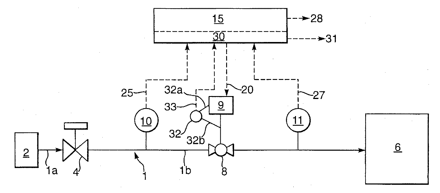
과압 보호 시스템은, 압력 감소 밸브 (4) 와 저압 유체 취급 시스템 (6) 사이에서 연장하는 도관부 (1) 와, 이 도관부 (1) 에 배열된 액츄에이터 (9) 가 제공된 차단 밸브 (8) 와, 도관부 (1) 에 있는 차단 밸브 (8) 의 양측에 배열된 압력 센서 (10, 11) 와, 압력 센서 (10, 11) 및 액츄에이터 (9) 와 연결되어 있고 도관부 (1) 내에서 고압을 감지하였을 때 신호 (28) 를 발생시키는 안전 제어 시스템 (15) 과, 액츄에이터 (9), 압력 센서 (10, 11), 및 안전 제어 시스템 (15) 과 연결되어 있으며 압력 센서 (10, 11) 와 차단 밸브 (8) 를 점검하는 자가-진단 시스템 (30) 으로 이루어지고, 상기 자가-진단 시스템 (30) 은, 차단 밸브 (8) 와 압력 센서 (10, 11) 중 어느 하나 또는 둘 모두에서 고장을 감지하였을 때 신호 (31) 를 발생시킨다.
과압 보호 시스템
The overpressure protection system includes a shutoff valve (8) provided with a conduit portion (1) extending between the pressure reducing valve (4) and the low pressure fluid handling system (6), and an actuator (9) arranged in the conduit portion (1); Pressure sensors 10 and 11 arranged on both sides of the shut-off valve 8 in the conduit 1 and connected to the pressure sensors 10 and 11 and the actuator 9 and sense high pressure in the conduit 1 Connected to the safety control system 15, the actuator 9, the pressure sensors 10, 11, and the safety control system 15, which generate a signal 28 when disconnected from the pressure sensors 10, 11. Consisting of a self-diagnosis system 30 for checking the valve 8, which self-diagnosis system 30 fails at either or both of the shutoff valve 8 and the pressure sensors 10, 11. When detected, a signal 31 is generated.
Overpressure protection system
Description
본 발명은 과압 보호 시스템에 관한 것이다. 과압 보호 시스템은, 파이프라인 또는 플랜트 등과 같이 저압에서 유체를 취급하는 설비가 과압에 노출되는 것을 보호한다. 과압은, 저압 유체를 취급하는 설비의 최대 허용가능한 작동압을 초과하는 압력을 말한다.The present invention relates to an overpressure protection system. An overpressure protection system protects equipment handling fluids at low pressure, such as pipelines or plants, from exposure to overpressure. Overpressure refers to a pressure that exceeds the maximum allowable working pressure of a facility that handles low pressure fluids.
상기 설비는 도관에 의해 고압원에 연결되어 있다. 설비내의 유체압력을 제어하기 위해서, 도관내에는 압력 감소 밸브가 배열되어 있다. 과압으로부터 설비를 보호하기 위해서, 압력 감소 밸브의 하류측 도관에는 과압 보호 시스템이 형성되어 있다.The facility is connected to a high voltage source by conduits. In order to control the fluid pressure in the installation, a pressure reducing valve is arranged in the conduit. In order to protect the installation from overpressure, an overpressure protection system is provided in the conduit downstream of the pressure reducing valve.
과압 보호 시스템은, 상류측 압력 감소 시스템의 고장에 의해 유발되는 과압으로부터 저압 설비를 보호한다. 추가로, 하류측 저압 설비내의 유체 유동의 폐쇄로 인한 과압으로부터 설비를 보호하는 것이다. 과압 보호 시스템의 고장으로 인하여 저압 설비내의 압력이 상류측 유체원의 고압과 동일하게 된다.The overpressure protection system protects the low pressure installation from overpressure caused by failure of the upstream pressure reduction system. In addition, it is to protect the plant against overpressure due to the closing of the fluid flow in the downstream low pressure plant. The failure of the overpressure protection system causes the pressure in the low pressure installation to equal the high pressure of the upstream fluid source.
종래의 과압 보호 시스템은, 저압 취급 시스템의 압력이 소정치를 초과하면 폐쇄되는 차단 밸브와, 차단 밸브의 고장에 대하여 보호하도록 저압 취급 시스템의 압력이 소정치를 초과하면 개방하는 기계적 릴리프 밸브를 포함한다. 종래 의 과압 보호 시스템의 단점은, 차단 밸브가 고장나서 기계적 릴리프 밸브가 개방되는 경우에 있어서, 저압 취급 시스템에 고압원이 여전히 연결되어 있다는 것이다. 더욱이, 본 출원인은 상기 릴리프 밸브의 신뢰성을 연구하였고, 단위 시간당 밸브 고장 횟수가 많았고, 즉 1000 년의 수명에 5 회 이상의 고장을 유발하였음을 발견하였다.Conventional overpressure protection systems include a shutoff valve that closes when the pressure in the low pressure handling system exceeds a predetermined value, and a mechanical relief valve that opens when the pressure in the low pressure handling system exceeds a predetermined value to protect against failure of the shutoff valve. do. A disadvantage of the conventional overpressure protection system is that in the case of a breakdown valve failure and the mechanical relief valve opening, a high pressure source is still connected to the low pressure handling system. Furthermore, the applicant studied the reliability of the relief valve and found that the number of valve failures per unit time was high, that is, it caused five or more failures in the life of 1000 years.
본 발명의 목적은 매우 낮은 고장율을 가진 과압 보호 시스템을 제공하는 것이다.It is an object of the present invention to provide an overpressure protection system with a very low failure rate.
결국, 본 발명에 따른 과압 보호 시스템은, 압력 감소 밸브와 저압 유체 취급 시스템 사이에서 연장되는 도관부와, 이 도관부에 배열된 액츄에이터가 제공된 차단 밸브와, 도관부에 있는 차단 밸브의 양측에 배열된 압력 센서와, 압력 센서 및 액츄에이터와 연결되어 있으며 도관부내에서 고압을 감지하였을 때 신호를 발생시키는 안전 제어 시스템과, 액츄에이터, 압력 센서, 및 안전 제어 시스템과 연결되어 있으며 압력 센서와 차단 밸브를 점검하는 자가-진단 시스템으로 이루어지고, 이 자가-진단 시스템은, 차단 밸브와 압력 센서 중 어느 하나 또는 둘 모두에서 고장을 감지하였을 때 신호를 발생시킨다.As a result, the overpressure protection system according to the present invention comprises a shutoff valve provided with a conduit extending between a pressure reducing valve and a low pressure fluid handling system, an actuator arranged in the conduit and a pressure sensor arranged on both sides of the shutoff valve in the conduit. And a safety control system that is connected to a pressure sensor and an actuator and that generates a signal when a high pressure is detected in the conduit section, and is connected to an actuator, a pressure sensor, and a safety control system, and checks the pressure sensor and the shut-off valve. This diagnostic system consists of a diagnostic system that generates a signal when a fault is detected at either or both of the shutoff valve and the pressure sensor.
본 발명은 첨부된 도면을 참조하여 보다 자세히 설명될 것이다.The invention will be explained in more detail with reference to the accompanying drawings.
도 1 은, 고압원 (2) 으로부터 압력 감소 밸브 (4) 까지 연장되는 제 1 도관부 (1a) 와, 압력 감소 밸브 (4) 로부터 저압 유체 취급 시스템 (6) 까지 연장되는 제 2 도관부 (1b) 를 포함하는 도관 (1) 을 도시한 개략도.1 shows a
제 2 도관부 (1b) 에는 액츄에이터 (9) 가 형성된 차단 밸브 (8) 가 배열되어 있다. 차단 밸브 (8) 는 예를 들어 볼 밸브이다. 추가로, 도관부 (1b) 에 있는 차단 밸브 (8) 의 양측에는 압력 센서 (10, 11) 가 배열되어 있다.The
과압 보호 시스템은 도관 (20) 을 통하여 액츄에이터 (9) 에 지령하는 안전 제어 시스템 (15) 을 더 포함하고 있다. 또한, 안전 제어 시스템 (15) 은 센서 신호를 안전 제어 시스템 (15) 으로 전송하는 도관 (25, 27) 을 통하여 센서 (10, 11) 와 연결되어 있다. 도관 (20, 25, 27) 은 전기 신호를 전송하는 도관인 것이 적절하다. 하지만, 도관은 유압 또는 기계적 신호를 전송할 수 있고, 또는 이 도관은 라디오 신호를 바탕으로 하는 통신 시스템으로 대체될 수 있다. 안전 제어 시스템 (15) 은, 도관부 (1) 내에서 고압을 감지하였을 때 신호 (28) 를 발생시킨다.The overpressure protection system further includes a
정상 작동시, 압력 센서 (10, 11) 가 소정치 이하의 압력을 감지하면 안전 제어 시스템 (15) 은 도관부 (1b) 에 배열된 차단 밸브 (8) 를 개방 위치에 둔다. 하지만, 압력 센서 (10, 11) 중 어느 하나라도 소정치를 초과하는 압력을 감지하였다면, 안전 제어 시스템 (15) 은 액츄에이터 (9) 가 차단 밸브 (8) 를 폐쇄하도록 만든다. 이러한 방식으로, 저압 설비는 과압으로부터 보호되고 있다. 추가로, 경고 신호가 작업자에게 발해지고 이 경고 신호는 또한 저압 유체 취급 시스템의 작동을 중단시킬 수 있는 것이 적절하다. 저압 유체 취급 시스템이 파이프라인인 경우에는 파이프라인이 폐쇄될 것이고, 저압 유체 취급 시스템이 플랜트인 경우에는 플랜트의 작동이 중단될 것이다.In normal operation, when the
안전 제어 시스템 (15) 은, 액츄에이터 (9) 를 직접 통전시키거나, 이 액츄에이터 (9) 를 통전시키도록 별개의 파워원에 지령할 수 있다.The
과압 보호 시스템은, 차단 밸브 (8) 와 압력 센서 (10, 11) 를 점검하는 자가-진단 시스템 (30) 을 더 포함하고 있다. 자가-진단 시스템 (30) 은, 차단 밸브 (8) 와 압력 센서 (10, 11) 중 어느 하나 또는 차단 밸브 (8) 와 압력 센서 (10, 11) 둘 다에서 고장을 감지하였을 때 신호 (31) 를 발생시킨다. 작업자에게 신호 (31) 가 주어지고, 이 신호 (31) 가 또한 소정의 시간내에 저압 유체 취급 시스템의 작동을 중단시킬 수 있다. 저압 유체 취급 시스템이 파이프라인인 경우에는 파이프라인이 폐쇄될 수 있고, 저압 유체 취급 시스템이 플랜트인 경우에는 플랜트의 작동이 중단될 수 있다. 자가-진단 시스템 (30) 은, 안전 제어 시스템 (15), 엑츄에이터 (9), 및 압력 센서 (10, 11) 와 연결되어 있다. 액츄에이터 (9) 및 압력 센서 (10, 11) 와의 연결은 안전 제어 시스템 (15) 과 동일한 도관을 통하여 이루어진다. 다른 방법으로, 안전 제어 시스템 (15) 을 통하여 연결하게 된다. 도관 (20) 을 통하여 액츄에이터에 지령이 보내진 경우에 있어서, 비상시에는 안전 제어 시스템 (15) 으로부터의 지령이 자가-진단 시스템 (30) 으로부터의 어떠한 지령에 우선하도록, 상기 지령은 안전 제어 시스템 (15) 으로부터의 지령에 부가된다. 액츄에이터 (9) 에 공급된 파워와 밸브 본체 (비도시) 의 위치에 대한 정보는, 도관 (23a) 에 의해 액츄에이터에 연결되고 도관 (23b) 에 의해 밸브대 (valve stem) 에 연결된 센서 결합부 (32) 에 의해 감지된다. 상기 정보는 도관 (33) 을 통하여 자가-진단 시스템에 제공된다. 도관 (33) 은 전기 신호를 전송하는 도관인 것이 적절하지만, 이 도관은, 유압 또는 기계적 신호도 전달할 수 있고, 또는 라디오 신호에 바탕을 두는 통신 시스템으로 대체될 수 있다.The overpressure protection system further includes a self-
신뢰성 없는 과압 보호 시스템은 바람직하지 않음을 이해할 것이다. 자가-진단 시스템 (30) 은, 차단 밸브 (8) 와 압력 센서 (10, 11) 중 어느 하나의 고장 또는 둘 다의 고장을 감지하였을 때 신호 (31) 를 발생시킨다. 고장을 감지하기 위해서, 자가-진단 시스템 (30) 은 여러 개의 시험을 연속적으로 수행하도록 프로그램화되어 있다. 자가-진단 시스템 (30) 은 과압 보호 시스템의 신뢰성을 상당히 증가시켜준다.It will be appreciated that unreliable overpressure protection systems are not desirable. The self-
자가-진단 시스템 (30) 은 과압 보호 시스템의 시험을 수행하도록 적절하게 프로그램화되고, 과압 보호 시스템은 압력 센서 (10, 11), 작동되는 차단 밸브 (8), 및 연결 라인의 정확한 성능을 시험하도록 구성되고, 이 연결 라인은 센서 (10, 11), 액츄에이터 (9), 및 안전 제어 시스템 (15) 사이에서 연장한다.The self-
시스템 시험은, 차단 밸브 (8) 의 폐쇄를 시작하도록 차단 밸브 (8) 의 밸브 본체 (비도시) 를 변위시키는 단계, 차단 밸브 (8) 의 상류측과 하류측에서 압력 센서 (10, 11) 에 의해 측정된 압력을 기록하는 단계, 차단 밸브 (8) 를 가로지르는 압력차가 소정의 한계치보다 크고 상류측 압력이 하류측 압력보다 클 때 밸브 본체의 변위를 중지하는 단계, 및 그 후 차단 밸브 (8) 를 재개방하는 단계를 포함한다.The system test includes displacing the valve body (not shown) of the
상기 시험의 제 1 단계에 있어서, 자가-진단 시스템 (30) 은 차단 밸브 (8) 를 폐쇄하도록 밸브 본체의 변위를 시작하기 위해서 도관 (20) 을 통해 액츄에이터 (9) 를 작동시킬 수 있다. 차단 밸브 (8) 를 폐쇄하도록 지령을 보내어 지령을 실행하여 차단 밸브 (8) 를 폐쇄하는 효과를 감지하는 것을 포함하는 체인이 적절하게 그 기능을 한다면, 상류측 센서 (10) 는 하류측 압력 센서 (11) 에 의해 측정된 압력보다 큰 증가된 압력을 측정하기 시작할 것이다. 압력 신호는 도관 (25, 27) 을 통하여 자가-진단 시스템 (30) 에 보내진다. 차단 밸브 (8) 를 가로지르는 압력차가 소정의 한계치보다 크고, 센서 (10) 에 의해 감지된 상류측 압력이 센서 (11) 에 의해 감지된 하류측 압력보다 클 때, 자가-진단 시스템 (30) 은 차단 밸브 (8) 의 밸브 본체의 변위를 중지한 뒤 차단 밸브 (8) 를 재개방하도록 지령한다. 차단 밸브 (8) 를 가로지르는 압력차가 저압 유체 취급 시스템 (6) 의 작동에 불리한 영향을 미치지 않도록 상기 소정의 한계치가 선택된다. 압력차가 감지되지 않는 경우에는 체인의 일부가 고장났음을 지령하도록 신호 (31) 가 발생하게 된다.In the first step of the test, the self-
시스템 시험시, 자가-진단 시스템 (30) 은, 밸브 본체의 변위와 액츄에이터 (9) 에 공급된 파워를 감지하여 기록하고, 이들을 예상 변위 및 파워와 비교한다. 이 단계에서, 차단 밸브 (8) 상류측과 하류측의 압력 센서 (10, 11) 및 차단 밸브 (8) 의 모든 기능이 점검된다.In the system test, the self-
자가-진단 시스템 (30) 은, 상기 시험이 성공적이어서 차단 밸브의 변위 및 액츄에이터에 공급된 파워가 예상 변위 및 파워와 바람직하게 비교되었음을, 또는 시험이 성공적이지 않아서 차단 밸브의 변위 및 액츄에이터에 공급된 파워가 예상 변위 및 파워와 바람직하게 비교되지 않았음을 나타내는 신호 (31) 를 발생시킨다. 이를 위해, 자가-진단 시스템 (30) 은, 액츄에이터 (9) 가 차단 밸브 (9) 의 밸브 본체를 변위시키도록 만드는 단계, 밸브 본체의 변위 및 액츄에이터 (9) 에 공급된 파워를 예상 변위 및 파워와 비교하는 단계, 및 상기 변위 또는 파워가 예상 변위 또는 파워와 동일하지 않으면 신호 (31) 를 보내는 단계를 실시하도록 또한 프로그램화된다. 자가-진단 시스템 (30) 은, 액츄에이터 (9) 를 통전시킴으로써, 액츄에이터 (9) 가 차단 밸브 (8) 를 폐쇄하도록 변위되도록 만든다. 액츄에이터에 공급된 파워와 밸브 본체의 위치는 센서 결합부 (32) 에 의해 기록되고, 이 정보는 도관 (33) 을 통하여 자가-진단 시스템 (30) 에 제공된다. 상기 변위 또는 파워가 예상 변위 또는 파워와 동일하지 않으면, 자가-진단 시스템 (30) 은 신호 (31) 를 보낸다. 이러한 시험을 밸브 시험이라 한다.The self-
차단 밸브 (8) 가 전기적으로 작동되면, 액츄에이터에 흐르는 전류가 파워 대신에 사용될 수 있다. 또한, 액츄에이터가 공기 등의 유체에 의해 작동되는 액츄에이터라면, 유체 압력이 사용된다. 전류 또는 압력은 센서 결합부 (32) 에 의해 감지되어 도관 (33) 을 통하여 자가-진단 시스템 (30) 에 제공된다.If the
밸브 시험에 있어서, 차단 밸브 (8) 의 밸브 본체의 행정 일부에 걸쳐서 또는 차단 밸브 (8) 의 밸브 본체의 전체 행정에 걸쳐서 밸브 변위가 이루어질 수 있다.
In the valve test, a valve displacement can be made over a part of the stroke of the valve body of the
과압 보호 시스템의 이러한 주기적인 시험 외에도, 차단 밸브 (8) 가 개방 위치 시스템내에 있을 때, 압력 센서 (10, 11) 는 자가-진단 시스템 (30) 에 의해 연속적으로 모니터링된다. 이러한 센서 시험을 수행하기 위해서, 자가-진단 시스템 (30) 은, 압력 센서 (10, 11) 로 압력을 연속 측정하는 단계, 압력차를 계산하는 단계, 이 압력차가 소정의 한계치보다 크다면 신호 (31) 를 보내는 단계를 실시하도록 또한 프로그램화된다. 이러한 시험은, 차단 밸브 (8) 가 개방되는 한 연속적으로 실시되고, 압력 센서 (10, 11) 를 점검하게 된다. 압력 센서 (10, 11) 의 신호는, 각각의 도관 (25, 27) 을 통하여 자가-진단 시스템 (30) 으로 보내진다. 압력차가 계산되어, 압력차의 절대값이 소정의 한계치보다 작으면 압력 센서 (10, 11) 는 올바르게 작동하고 있는 것이다. 하지만, 이러한 경우가 아니라면, 압력 센서 (10 또는 11) 에서 고장이 발견되었음을 나타내는 신호 (31) 가 발해진다. 추가로, 고장을 해소하지 않으면, 저압 설비의 작동을 중단시키기 위해서 소정의 시간내에 차단 밸브 (8) 가 폐쇄된다. 도관부 (1) 를 통과하는 유동의 작은 변화는 차단 밸브 (8) 에 걸쳐 압력 강하를 유발할 것이고, 소정의 한계치를 정할 때, 이러한 압력 강하가 고려되어야 함을 이해할 것이다.In addition to this periodic test of the overpressure protection system, when the
시스템 시험 및 밸브 시험은 시험 라운드와 한번의 연속 시험에서 시험 라운드 사이에 일정한 간격을 두고서 차례로 실시될 수 있고, 센서 시험은 두 시험 라운드 사이에서 연속 실시된다. 다른 방법으로, 각각의 시험은 규칙적인 간격으로 실시될 수 있고, 각 시험에 있어서 두 시험 사이의 시간은 다르다.The system test and the valve test can be conducted in sequence at regular intervals between the test round and the test round in one continuous test, and the sensor test is performed continuously between the two test rounds. Alternatively, each test can be conducted at regular intervals, and the time between the two tests is different for each test.
도면에서 보면, 자가-진단 시스템 (30) 은 안전 제어 시스템 (15) 의 일부로 되어 있다. 하지만, 전술한 기능이 유지되도록 연결 라인이 연결되었다고 가정하면, 자가-진단 시스템은 안전 제어 시스템과 분리될 수 있다.In the figure, the self-
도면을 참조하여 전술한 본 발명의 실시형태에 있어서, 상류측 압력 센서 (10) 와 하류측 압력 센서 (11) 가 제공된 단일 차단 밸브 (8) 가 도관부 (1) 에 설치된다. 다른 방법으로, 도관부 (1) 에는 2 이상의 차단 밸브가 일렬로 형성될 수 있고, 이 각각의 차단 밸브는 상류측 압력 센서와 하류측 압력 센서를 구비한다. 2 개의 인접한 차단 밸브 사이에 2 개의 압력 센서가 있는 경우에, 하나의 차단 밸브의 하류측 압력 센서가 다른 차단 밸브의 상류측 압력 밸브가 되도록 2 개의 압력 센서 중 하나가 생략될 수 있다. 그 후, 2 이상의 밸브에 전술한 시험이 개별적으로 실시된다. 차단 밸브는, 전용의 자가-진단 시스템과 공통의 안전 제어 시스템, 또는 각각의 차단 밸브용 안전 제어 시스템을 구비할 수 있다. 다른 방법으로, 차단 밸브는 하나의 자가-진단 시스템을 구비할 수 있고, 하나의 안전 제어 시스템은 모든 차단 밸브에 작용한다.In the embodiment of the present invention described above with reference to the drawings, a
요약하면, 본 발명은 신뢰성이 증가한 과압 보호 시스템을 제공하여 압력 해제 시스템이 필요하지 않다. 2 개의 차단 밸브를 포함하는 본 발명에 따른 과압 보호 시스템의 구성에서는, 과압 보호 시스템의 수명이 50,000 년 이라고 할 때 1 회 이하의 고장율이 얻어진다.In summary, the present invention provides an overpressure protection system with increased reliability, thus eliminating the need for a pressure relief system. In the configuration of the overpressure protection system according to the present invention including two shutoff valves, a failure rate of one time or less is obtained when the life of the overpressure protection system is 50,000 years.
Claims (11)
Applications Claiming Priority (2)
| Application Number | Priority Date | Filing Date | Title |
|---|---|---|---|
| EP01309291 | 2001-11-01 | ||
| EP01309291.1 | 2001-11-01 |
Publications (2)
| Publication Number | Publication Date |
|---|---|
| KR20050042212A KR20050042212A (en) | 2005-05-06 |
| KR100970848B1 true KR100970848B1 (en) | 2010-07-16 |
Family
ID=8182412
Family Applications (1)
| Application Number | Title | Priority Date | Filing Date |
|---|---|---|---|
| KR1020047006528A KR100970848B1 (en) | 2001-11-01 | 2002-11-01 | Over-pressure protection system |
Country Status (7)
| Country | Link |
|---|---|
| US (1) | US6880567B2 (en) |
| EP (1) | EP1440267B1 (en) |
| JP (1) | JP4344884B2 (en) |
| KR (1) | KR100970848B1 (en) |
| DE (1) | DE60206405T2 (en) |
| NO (1) | NO328992B1 (en) |
| WO (1) | WO2003038325A1 (en) |
Families Citing this family (79)
| Publication number | Priority date | Publication date | Assignee | Title |
|---|---|---|---|---|
| GB0213635D0 (en) * | 2002-06-13 | 2002-07-24 | Alpha Thames Ltd | Pressure protection system |
| US20060278281A1 (en) * | 2005-05-24 | 2006-12-14 | Gynz-Rekowski Gunther V | Apparatus and method for closing a fluid path |
| GB2439552B (en) * | 2006-05-20 | 2011-03-02 | Vetco Gray Controls Ltd | Pipeline protection system |
| US20080078586A1 (en) * | 2006-08-31 | 2008-04-03 | Tettleton Tab S | Mud systems with pressure relief valve |
| US8725434B2 (en) * | 2006-12-29 | 2014-05-13 | Saudi Arabian Oil Company | Wellhead hips with automatic testing and self-diagnostics |
| US7905251B2 (en) * | 2006-12-29 | 2011-03-15 | Saudi Arabian Oil Company | Method for wellhead high integrity protection system |
| KR100884958B1 (en) * | 2007-02-14 | 2009-02-23 | 엘지전자 주식회사 | Sensor module and fluid circulation system having the same |
| US8016548B2 (en) * | 2007-03-30 | 2011-09-13 | Mark R. Ziegenfuss | Water supply tunnel secondary purpose turbine electric power generator system |
| US8870233B2 (en) | 2007-07-03 | 2014-10-28 | S.P.M. Flow Control, Inc. | Swivel joint with uniform ball bearing requirements |
| EP2088485A1 (en) * | 2008-02-06 | 2009-08-12 | Siemens Aktiengesellschaft | Monitoring of a device or installation with a safety-oriented function and method therefor |
| JP2012507090A (en) | 2008-10-27 | 2012-03-22 | ミューラー インターナショナル エルエルシー | Infrastructure monitoring system and method |
| EA201171267A1 (en) | 2009-04-20 | 2012-04-30 | Эс.Пи.Эм. ФЛОУ КОНТРОЛ, ИНК. | DEPOSIT VALVE FOR PRESSURE HEAT PIPE |
| KR101288578B1 (en) * | 2009-05-13 | 2013-07-22 | 필즈엔지니어링 주식회사 | The mechanical apparatus and method for reducing pressure in column of refinery or petrochemical process |
| JP2012527706A (en) | 2009-05-22 | 2012-11-08 | ミューラー インターナショナル インコーポレイテッド | Infrastructure monitoring apparatus, system, and method |
| FR2946401B1 (en) * | 2009-06-03 | 2015-10-16 | Airbus France | ACTUATOR WITH ELECTRIC POWER AND METHOD OF CONTROLLING SUCH ACTUATOR. |
| US8465001B2 (en) | 2009-06-03 | 2013-06-18 | S.P.M. Flow Control, Inc. | Plug valve indicator |
| US8479734B2 (en) * | 2009-11-10 | 2013-07-09 | John Steven Wood | Overpressure protection system and method for a hyperbaric chamber |
| JP5518537B2 (en) * | 2010-03-18 | 2014-06-11 | 株式会社ケーヒン | Shut-off valve failure diagnosis device |
| CA3177996A1 (en) | 2010-06-16 | 2011-12-22 | Mueller International, Llc | Infrastructure monitoring devices, systems, and methods |
| US9080683B2 (en) * | 2011-02-17 | 2015-07-14 | Fisher Controls International Llc | Method and apparatus for partial stroke testing of an emergency shutdown valve |
| US8838413B2 (en) | 2011-05-12 | 2014-09-16 | Saudi Arabian Oil Company | Valve actuator fault analysis system |
| US8833390B2 (en) | 2011-05-31 | 2014-09-16 | Mueller International, Llc | Valve meter assembly and method |
| US8893803B1 (en) * | 2011-07-15 | 2014-11-25 | Trendsetter Engineering, Inc. | Safety relief valve system for use with subsea piping and process for preventing overpressures from affecting the subsea piping |
| US8855569B2 (en) | 2011-10-27 | 2014-10-07 | Mueller International, Llc | Systems and methods for dynamic squelching in radio frequency devices |
| US20130118609A1 (en) * | 2011-11-12 | 2013-05-16 | Thomas Neil Horsky | Gas flow device |
| US9846440B2 (en) | 2011-12-15 | 2017-12-19 | Honeywell International Inc. | Valve controller configured to estimate fuel comsumption |
| US8947242B2 (en) | 2011-12-15 | 2015-02-03 | Honeywell International Inc. | Gas valve with valve leakage test |
| US9835265B2 (en) | 2011-12-15 | 2017-12-05 | Honeywell International Inc. | Valve with actuator diagnostics |
| US9074770B2 (en) | 2011-12-15 | 2015-07-07 | Honeywell International Inc. | Gas valve with electronic valve proving system |
| US9995486B2 (en) | 2011-12-15 | 2018-06-12 | Honeywell International Inc. | Gas valve with high/low gas pressure detection |
| US8839815B2 (en) | 2011-12-15 | 2014-09-23 | Honeywell International Inc. | Gas valve with electronic cycle counter |
| US9851103B2 (en) * | 2011-12-15 | 2017-12-26 | Honeywell International Inc. | Gas valve with overpressure diagnostics |
| US8905063B2 (en) | 2011-12-15 | 2014-12-09 | Honeywell International Inc. | Gas valve with fuel rate monitor |
| US9557059B2 (en) | 2011-12-15 | 2017-01-31 | Honeywell International Inc | Gas valve with communication link |
| US8899264B2 (en) | 2011-12-15 | 2014-12-02 | Honeywell International Inc. | Gas valve with electronic proof of closure system |
| US9695802B2 (en) * | 2012-05-22 | 2017-07-04 | United Technologies Corporation | Wind turbine load mitigation |
| US20130312421A1 (en) * | 2012-05-24 | 2013-11-28 | Solar Turbines Incorporated | Fuel control system for a gas turbine engine |
| GB2520218A (en) | 2012-08-16 | 2015-05-13 | Spm Flow Control Inc | Plug valve having preloaded seal segments |
| US9273543B2 (en) | 2012-08-17 | 2016-03-01 | S.P.M. Flow Control, Inc. | Automated relief valve control system and method |
| US9322243B2 (en) | 2012-08-17 | 2016-04-26 | S.P.M. Flow Control, Inc. | Automated relief valve control system and method |
| US10422531B2 (en) | 2012-09-15 | 2019-09-24 | Honeywell International Inc. | System and approach for controlling a combustion chamber |
| US9234661B2 (en) | 2012-09-15 | 2016-01-12 | Honeywell International Inc. | Burner control system |
| CN103133459B (en) * | 2013-02-07 | 2015-10-07 | 中联重科股份有限公司 | The overflow method for early warning of hydraulic system, overflow prior-warning device and engineering machinery |
| USD707332S1 (en) | 2013-03-15 | 2014-06-17 | S.P.M. Flow Control, Inc. | Seal assembly |
| USD707797S1 (en) | 2013-03-15 | 2014-06-24 | S.P.M. Flow Control, Inc. | Seal segment |
| US9568138B2 (en) | 2013-07-01 | 2017-02-14 | S.P.M. Flow Control, Inc. | Manifold assembly |
| EP2868970B1 (en) | 2013-10-29 | 2020-04-22 | Honeywell Technologies Sarl | Regulating device |
| US10024439B2 (en) | 2013-12-16 | 2018-07-17 | Honeywell International Inc. | Valve over-travel mechanism |
| US9494249B2 (en) | 2014-05-09 | 2016-11-15 | Mueller International, Llc | Mechanical stop for actuator and orifice |
| US9565620B2 (en) | 2014-09-02 | 2017-02-07 | Mueller International, Llc | Dynamic routing in a mesh network |
| US9841122B2 (en) | 2014-09-09 | 2017-12-12 | Honeywell International Inc. | Gas valve with electronic valve proving system |
| US9645584B2 (en) | 2014-09-17 | 2017-05-09 | Honeywell International Inc. | Gas valve with electronic health monitoring |
| US9933088B2 (en) * | 2015-06-10 | 2018-04-03 | Woodward, Inc. | Rotary actuated valve with position indicator |
| WO2016205208A1 (en) | 2015-06-15 | 2016-12-22 | S.P.M. Flow Control, Inc. | Full-root-radius-threaded wing nut having increased wall thickness |
| CN105003715B (en) * | 2015-08-13 | 2017-07-11 | 湖南山源安自控系统有限公司 | It is a kind of that there is the emergent electro-hydraulic drive system of gate valve and gate valve for closing valve function |
| US10677365B2 (en) | 2015-09-04 | 2020-06-09 | S.P.M. Flow Control, Inc. | Pressure relief valve assembly and methods |
| KR101885162B1 (en) * | 2015-11-27 | 2018-08-06 | 삼성중공업(주) | Pressure relief valve and apparatus for monitoring valve |
| US10503181B2 (en) | 2016-01-13 | 2019-12-10 | Honeywell International Inc. | Pressure regulator |
| US9896911B2 (en) * | 2016-01-26 | 2018-02-20 | Trendsetter Vulcan Offshore, Inc. | Subsea pressure protection system |
| GB2547675A (en) * | 2016-02-25 | 2017-08-30 | Ge Oil & Gas Uk Ltd | Subsea high integrity pipeline protection system with bypass |
| US10753852B2 (en) | 2016-05-10 | 2020-08-25 | Saudi Arabian Oil Company | Smart high integrity protection system |
| JP6670167B2 (en) * | 2016-05-12 | 2020-03-18 | 株式会社神戸製鋼所 | Accumulator for hydraulic work machine |
| US10564062B2 (en) | 2016-10-19 | 2020-02-18 | Honeywell International Inc. | Human-machine interface for gas valve |
| CN106568588B (en) * | 2016-11-03 | 2018-10-26 | 北京市公用事业科学研究所 | A kind of inflow-rate of water turbine stop valve reliability automatic detection device |
| US20190352888A1 (en) * | 2017-01-14 | 2019-11-21 | Mario LARACH | Smart monitoring unit apparatus for real-time monitoring and active management of upstream and downstream pressure and flow, incorporating self-cleaning and plug-and-play maintenance |
| US11261726B2 (en) | 2017-02-24 | 2022-03-01 | Saudi Arabian Oil Company | Safety integrity level (SIL) 3 high-integrity protection system (HIPS) fully-functional test configuration for hydrocarbon (gas) production systems |
| US10570712B2 (en) * | 2017-04-17 | 2020-02-25 | Saudi Arabian Oil Company | Protecting a hydrocarbon fluid piping system |
| US10648621B2 (en) | 2017-07-26 | 2020-05-12 | John B. King | Trapped gas transfer and metering system |
| US11174625B2 (en) | 2017-11-28 | 2021-11-16 | Truth Holding Llc | Method and apparatus for isolating a pressure-driven system from a source |
| JP6944702B2 (en) * | 2017-11-30 | 2021-10-06 | 株式会社フジキン | Fluid circuit safety system |
| US11073281B2 (en) | 2017-12-29 | 2021-07-27 | Honeywell International Inc. | Closed-loop programming and control of a combustion appliance |
| US10663988B2 (en) | 2018-03-26 | 2020-05-26 | Saudi Arabian Oil Company | High integrity protection system for hydrocarbon flow lines |
| KR101890343B1 (en) * | 2018-04-04 | 2018-08-21 | (주)티에프에스글로발 | Turbine Fast Acting valve replacement device |
| US10697815B2 (en) | 2018-06-09 | 2020-06-30 | Honeywell International Inc. | System and methods for mitigating condensation in a sensor module |
| US11608840B2 (en) * | 2018-08-21 | 2023-03-21 | Michael Yuan | Piezoelectric ring bender servo valve assembly for aircraft flight control actuation and fuel control systems |
| NO344761B1 (en) * | 2018-08-24 | 2020-04-14 | Inline Test As | Portable system for testing a valve in a process plant |
| KR102043122B1 (en) * | 2019-05-23 | 2019-11-11 | 주식회사 옥광엔지니어링 | Abnormal pressure control ball valve for marine plants and anomaly pressure control system including it |
| US11078755B2 (en) | 2019-06-11 | 2021-08-03 | Saudi Arabian Oil Company | HIPS proof testing in offshore or onshore applications |
| GB2599980A (en) * | 2020-05-11 | 2022-04-20 | Dril Quip Inc | A well production system, a computer-readable medium, and a method |
Citations (3)
| Publication number | Priority date | Publication date | Assignee | Title |
|---|---|---|---|---|
| US3844310A (en) | 1972-01-20 | 1974-10-29 | F Brindisi | Pressure relief valve unit |
| US4572237A (en) | 1984-08-10 | 1986-02-25 | Value Oriented Technology Inc. | Function assist control for pressure relief valve |
| US5836348A (en) | 1995-12-28 | 1998-11-17 | Appalachian Controls Environmental | Pilot controlled blanketing valve |
Family Cites Families (4)
| Publication number | Priority date | Publication date | Assignee | Title |
|---|---|---|---|---|
| GB2062812B (en) | 1979-10-20 | 1984-08-30 | Furmanite Int Ltd | Valve testing |
| KR890007306A (en) * | 1987-10-30 | 1989-06-19 | 제트.엘.더머 | Online valve diagnostic monitoring system |
| FI104129B1 (en) * | 1996-06-11 | 1999-11-15 | Neles Jamesbury Oy | Procedure for monitoring the condition of control valve |
| US6123093A (en) | 1998-04-30 | 2000-09-26 | D'antonio Consultants International, Inc. | System for controlling fluid flow |
-
2002
- 2002-11-01 WO PCT/EP2002/012279 patent/WO2003038325A1/en active IP Right Grant
- 2002-11-01 EP EP02787551A patent/EP1440267B1/en not_active Expired - Fee Related
- 2002-11-01 JP JP2003540560A patent/JP4344884B2/en not_active Expired - Fee Related
- 2002-11-01 DE DE60206405T patent/DE60206405T2/en not_active Expired - Lifetime
- 2002-11-01 US US10/494,099 patent/US6880567B2/en not_active Expired - Fee Related
- 2002-11-01 KR KR1020047006528A patent/KR100970848B1/en not_active IP Right Cessation
-
2004
- 2004-05-28 NO NO20042220A patent/NO328992B1/en not_active IP Right Cessation
Patent Citations (3)
| Publication number | Priority date | Publication date | Assignee | Title |
|---|---|---|---|---|
| US3844310A (en) | 1972-01-20 | 1974-10-29 | F Brindisi | Pressure relief valve unit |
| US4572237A (en) | 1984-08-10 | 1986-02-25 | Value Oriented Technology Inc. | Function assist control for pressure relief valve |
| US5836348A (en) | 1995-12-28 | 1998-11-17 | Appalachian Controls Environmental | Pilot controlled blanketing valve |
Also Published As
| Publication number | Publication date |
|---|---|
| EP1440267B1 (en) | 2005-09-28 |
| US6880567B2 (en) | 2005-04-19 |
| US20040261856A1 (en) | 2004-12-30 |
| JP2005530097A (en) | 2005-10-06 |
| NO328992B1 (en) | 2010-07-12 |
| WO2003038325A1 (en) | 2003-05-08 |
| DE60206405T2 (en) | 2006-03-16 |
| DE60206405D1 (en) | 2006-02-09 |
| KR20050042212A (en) | 2005-05-06 |
| NO20042220L (en) | 2004-07-14 |
| EP1440267A1 (en) | 2004-07-28 |
| JP4344884B2 (en) | 2009-10-14 |
Similar Documents
| Publication | Publication Date | Title |
|---|---|---|
| KR100970848B1 (en) | Over-pressure protection system | |
| EP2122230B1 (en) | Apparatus and method for wellhead high integrity protection system | |
| RU2378678C2 (en) | Method and device for controlling regulating valve using control loop, as well as for detecting faults in said loop | |
| US7621293B2 (en) | Versatile emergency shutdown device controller implementing a pneumatic test for a system instrument device | |
| EP2217984B1 (en) | Wellhead flowline protection and testing system with esp speed controller and emergency isolation valve | |
| US7539560B2 (en) | Control valve and positioner diagnostics | |
| US8725434B2 (en) | Wellhead hips with automatic testing and self-diagnostics | |
| US20110133942A1 (en) | Apparatus and method for clustered wellhead high integrity protection system | |
| EP2666096A1 (en) | Wellhead hips with automatic testing and self-diagnostics | |
| CA2822052A1 (en) | Apparatus and method for clustered wellhead high integrity protection system |
Legal Events
| Date | Code | Title | Description |
|---|---|---|---|
| A201 | Request for examination | ||
| E902 | Notification of reason for refusal | ||
| E701 | Decision to grant or registration of patent right | ||
| GRNT | Written decision to grant | ||
| LAPS | Lapse due to unpaid annual fee |