KR100951135B1 - Overflow water treatment apparatus of confluent water drainage, manufacturing mathod of float media and float media - Google Patents
Overflow water treatment apparatus of confluent water drainage, manufacturing mathod of float media and float media Download PDFInfo
- Publication number
- KR100951135B1 KR100951135B1 KR1020070139203A KR20070139203A KR100951135B1 KR 100951135 B1 KR100951135 B1 KR 100951135B1 KR 1020070139203 A KR1020070139203 A KR 1020070139203A KR 20070139203 A KR20070139203 A KR 20070139203A KR 100951135 B1 KR100951135 B1 KR 100951135B1
- Authority
- KR
- South Korea
- Prior art keywords
- water
- treatment
- sewage
- water treatment
- unit
- Prior art date
Links
Images


Classifications
-
- C—CHEMISTRY; METALLURGY
- C02—TREATMENT OF WATER, WASTE WATER, SEWAGE, OR SLUDGE
- C02F—TREATMENT OF WATER, WASTE WATER, SEWAGE, OR SLUDGE
- C02F3/00—Biological treatment of water, waste water, or sewage
- C02F3/02—Aerobic processes
- C02F3/06—Aerobic processes using submerged filters
-
- C—CHEMISTRY; METALLURGY
- C02—TREATMENT OF WATER, WASTE WATER, SEWAGE, OR SLUDGE
- C02F—TREATMENT OF WATER, WASTE WATER, SEWAGE, OR SLUDGE
- C02F3/00—Biological treatment of water, waste water, or sewage
- C02F3/02—Aerobic processes
- C02F3/12—Activated sludge processes
- C02F3/1205—Particular type of activated sludge processes
- C02F3/1215—Combinations of activated sludge treatment with precipitation, flocculation, coagulation and separation of phosphates
-
- C—CHEMISTRY; METALLURGY
- C02—TREATMENT OF WATER, WASTE WATER, SEWAGE, OR SLUDGE
- C02F—TREATMENT OF WATER, WASTE WATER, SEWAGE, OR SLUDGE
- C02F1/00—Treatment of water, waste water, or sewage
- C02F2001/007—Processes including a sedimentation step
-
- C—CHEMISTRY; METALLURGY
- C02—TREATMENT OF WATER, WASTE WATER, SEWAGE, OR SLUDGE
- C02F—TREATMENT OF WATER, WASTE WATER, SEWAGE, OR SLUDGE
- C02F2201/00—Apparatus for treatment of water, waste water or sewage
- C02F2201/002—Construction details of the apparatus
- C02F2201/005—Valves
-
- Y—GENERAL TAGGING OF NEW TECHNOLOGICAL DEVELOPMENTS; GENERAL TAGGING OF CROSS-SECTIONAL TECHNOLOGIES SPANNING OVER SEVERAL SECTIONS OF THE IPC; TECHNICAL SUBJECTS COVERED BY FORMER USPC CROSS-REFERENCE ART COLLECTIONS [XRACs] AND DIGESTS
- Y02—TECHNOLOGIES OR APPLICATIONS FOR MITIGATION OR ADAPTATION AGAINST CLIMATE CHANGE
- Y02W—CLIMATE CHANGE MITIGATION TECHNOLOGIES RELATED TO WASTEWATER TREATMENT OR WASTE MANAGEMENT
- Y02W10/00—Technologies for wastewater treatment
- Y02W10/10—Biological treatment of water, waste water, or sewage
Abstract
본 발명은 강우유출수로 인하여 합류식하수도내에서 적정처리가 되지 않은 상태로 월류되는 하수의 처리를 위한 합류식하수도의 월류수 처리장치와, 그에 사용되는 부상여재의 제조방법 및 부상여재에 관한 것으로서, 강우에 의해 대량으로 유입되는 하수에 포함된 오염물을 신속하게 처리하는 월류수 처리장치, 부상여재의 제조방법 및 부상여재를 제공하는 것을 목적으로 한다. 상기의 목적을 달성하기 위한 본 발명에 따른 월류수 처리장치는 합류식 하수도의 월류수에 포함된 오염물질을 처리하는 하수처리공정에 있어서, 하수처리공정의 처리 용량을 넘는 월류수를 유입하는 유입부와, 상기 유입부가 하부에 연결되어 유입되는 월류수를 상향식으로 여과처리하는 처리조와, 상기 처리조의 하부에 설치되며 조대 협잡물을 여과하기 위한 침전여재를 갖는 하부 수처리부와, 상기 하부 수처리부의 상부에 마련되어 미세 오염물질을 여과하기 위한 부상여재층을 갖는 상부 수처리부와, 상기 상부 수처리부를 거쳐 여과된 월류수를 방류하는 방류부와, 상기 유입부로부터 원수를 유입하여 하향류로 순환하며 내부를 세정하는 역세부를 포함한다.The present invention relates to a sewage treatment apparatus for a combined sewage system for the treatment of sewage that flows in an untreated sewage system due to rainfall runoff, and to a method and a method for preparing a floating media used therein. It is an object of the present invention to provide a overflow water treatment apparatus for rapidly treating contaminants contained in sewage introduced by a large amount of wastewater, a method of manufacturing flotation media, and flotation media. In the wastewater treatment apparatus according to the present invention for achieving the above object in the sewage treatment process for treating contaminants contained in the overflow water of the combined sewer, the inlet for inflowing the excess water beyond the treatment capacity of the sewage treatment process, and Inlet is connected to the lower portion of the treatment tank for filtering the incoming overflow water from the bottom, the lower water treatment unit is installed in the lower portion of the treatment tank for filtering coarse contaminants, and the upper water treatment unit is provided on the upper micro-pollutants An upper water treatment unit having a flotation filter layer for filtering the water, a discharge unit for discharging the filtered overflowed water through the upper water treatment unit, and a backwash unit for circulating the raw water from the inlet to flow downward and cleaning the interior; do.
하수, 월류수, 수처리, 여재, 처리조, 침전지 Sewage, Overflow water, Water treatment, Media, Treatment tank, Settling basin
Description
본 발명은 강우유출수로 인하여 합류식하수도내에서 적정처리가 되지 않은 상태로 월류되는 하수의 처리를 위한 합류식하수도의 월류수 처리장치와, 그에 사용되는 부상여재의 제조방법 및 부상여재에 관한 것으로서, 보다 상세하게는 강우에 의해 대량으로 유입되는 하수에 포함된 오염물을 신속하게 처리하는 합류식하수도의 월류수 처리장치와, 그에 사용되는 부상여재의 제조방법 및 부상여재에 관한 것이다.The present invention relates to a sewage treatment apparatus for a combined sewage for the treatment of sewage that flows in an untreated sewage system due to rainfall runoff, and to a method and a method for preparing a floating media used therein. Preferably, the present invention relates to a combined sewage overflow treatment system for rapidly treating contaminants contained in sewage introduced by a large amount of rainfall, a method of manufacturing a floating filter used therein, and a floating filter.
일반적으로 강우시 발생되는 합류식 하수도의 월류수(CSOs)는 하수와 강우에 의한 지표유출수가 포함되어 있다. 이러한 지표유출수는 유기물, 영양물질, 박테리아, 탁도, 고형물, 기타 독성물질 등 다양한 오염물질이 포함되어 방류수역(하천과 호소 등)에 미치는 영향이 심각하며 강우 후 하천 수질악화 및 물고기의 집단폐사 등의 원인으로 작용하고 있다. 이러한 월류수의 특징은 토지이용 형태나 강우량 등에 따라 오염성상과 수질이 상이하며, 강우량에 따른 유량의 변동 폭이 상대 적으로 크며 강우 초기 세척현상(First Flush) 등에 의해 기존하수보다 오염도가 수배에 달하는 것이 일반적이나 기존의 하수처리장이나 배수펌프장 등을 통해서 별도의 처리없이 방류수역으로 배출되는 것이 현실이다. 이와 같이 합류식 하수도에서 강우시 배출되는 오염수의 농도는 표 1과 같다.In general, overflowed sewage (CSOs) from the sewer system includes surface runoff from sewage and rainfall. These surface effluents contain various pollutants such as organic matter, nutrients, bacteria, turbidity, solids, and other toxic substances, which have a serious impact on the discharge water (streams and lakes, etc.). It is acting as a cause. The characteristics of the overflowed water are different from the pollutant properties and the water quality according to the land use type and rainfall, and the fluctuation of the flow rate due to the rainfall is relatively large, and the pollution degree is several times higher than the existing sewage due to the first flush. In general, it is discharged into the discharge water without separate treatment through the existing sewage treatment plant or drainage pumping station. As such, the concentrations of contaminated water discharged during rainfall from the combined sewer are shown in Table 1.

이를 처리하기 위하여 하수도 시설기준에서는 합류식 하수도에서 공공수역의 수질보전을 위해 강우시에 배출되는 방류부하량을 저감하도록 하고 있으며 이를 위한 목표로 처리대상구역에서 배출되는 연간 BOD방류 부하량을 분류식 하수도로 전환하였을 경우 배출되는 연간 BOD 방류부하량과 같은 정도로 하거나 그 이하로 하도록 하고 있으며, 또한 관거 및 처리장계획시의 시설기준을 다음 표 2와 같이 제시하고 있다.In order to deal with this, the sewage facility standard reduces the discharge load discharged during rainfall for conserving the water quality of public waters in the combined sewage system, and aims to convert the annual BOD discharge load discharged from the treated area into a sewer. In this case, the discharge rate should be about the same or less than the annual discharge of BOD discharged, and the facility standards for conduit and treatment plant planning are shown in Table 2 below.

위의 표와 같이 각 개별 시설별로 용량의 기준이 상이 함에 따라 처리시설의 용량을 초과하는 하수의 발생은 필연적이며, 분류식하수도로 전환하였을 경우의 방류부하량과 같은 정도로 하기 위해서는 3Q 중 처리용량(편의상 1Q)을 초과하는 용량의 적정처리가 반드시 필요하다.As the table above shows that the capacity of each facility is different, it is inevitable that sewage exceeding the capacity of the treatment facility is inevitable. For convenience, titration of capacity exceeding 1Q) is essential.
도 1은 일반적인 합류식하수도에서의 하수처리공정을 간략하게 도시한 공정도이다. 일반적으로 하수처리공정은, 도 1에 도시된 바와 같이, 하수를 취수하여 비부패성 무기물 및 입자가 큰 부유물질을 제거하는 침사지(10)와, 고형물입자를 침전, 제거하는 일차 침전지(20)를 갖는다. 또한, 상기 일차 침전지(20)에서 배출된 하수에 포함된 유기물질이 미생물에 의해 제거되는 포기조(30)와, 상기 포기조(30)를 거친 하수에 포함된 이물질을 최종적으로 침전시키는 이차 침전지(40)를 거친 후, 소독 및 방류조(50)에서 약품 등에 의한 소독처리 후 방류된다.1 is a process diagram briefly showing a sewage treatment process in a general combined sewer. In general, the sewage treatment process, as shown in Figure 1, the sedimentation basin (10) to remove the non-perishable inorganic material and large suspended solids by taking the sewage, and the primary sedimentation basin (20) to precipitate and remove the solid particles Have In addition, the
이와 같이 구성된 종래의 하수처리공정은, 상기 1일차 침전지(10)를 하수처리공정의 후속처리용량(일례로, 1Q) 이상(일례로, 3Q)으로 설계하여 강우시 발생하는 하수를 간이 처리하여 방류수역으로 방류하도록 하였으나, 하수처리공정의 특성상 상기 일차 침전지(10)에는 유입되는 하수 외에도 하수처리공정 중 유기물제거 공정에서 발생하는 잉여 슬러지, 소화 및 탈수공정에서 발생하는 반송수 등 고농도의 기타 물질의 유입이 이루어지며, 이로 인하여 유입수보다 고농도의 방류수가 발생하는 경우가 빈발하게 되는 문제점과 한계가 발생한다.In the conventional sewage treatment process configured as described above, the
또한, 강우량이 많아지게 되면 유량증가에 따라 상기 일차 침전지(20) 내에 침전되어 있던 침전슬러지가 유속증가로 재부상하게 되어 침전효율 저하는 물론 후속 공정의 처리 효율 저하와 운전의 불안정을 야기하는 원인이 된다. 또한, 하수처리공정으로 유입되는 하수는 강우량의 변동에 따라 그 유입량이 수시로 변동되며, 이에 따라 기존의 시스템에서는 이러한 발생특성에 대해 적절한 대응이 매우 어려운 실정이다.In addition, if the rainfall increases, the sedimentation sludge settled in the
이에 대한 대안으로 하수처리공정의 후속처리용량(1Q)을 초과하는 하수량의 처리가 가능한 처리시설로 월류수 처리장치를 구축하고, 상기 월류수 처리장치에서 상기 하수처리공정에서 처리되지 못하고 방류되는 하수를 저감하는 것이 가장 경제적이며 실현 가능한 방안이 될 수 있다.As an alternative to this, a wastewater treatment system is constructed as a treatment facility capable of treating a sewage amount exceeding a subsequent treatment capacity (1Q) of the sewage treatment process, and the sewage that is not treated in the sewage treatment process and discharged from the sewage treatment apparatus is reduced. Can be the most economical and feasible solution.
종래의 강우시 발생되는 합류식 하수도 월류수의 처리방법은 하수처리장의 1차1 침전지(20)를 이용하거나, 스월조절조(Swirl Regulator) 또는 미세목 스크린 등 전처리를 목적으로 개발되어 단순히 협잡물 처리가 가능한 정도의 시설로, 하수처리장의 1차침전 처리 이상의 효율은 기대하기 어려운 것이 현실이다.Conventional sewage overflow water treatment method generated during the conventional rainfall is developed for the purpose of pretreatment such as the use of the
종래의 하수처리공정에서 월류수의 오염을 저감하기 위해 사용되는 방안으로는 다음 표 3과 같은 기술이 사용되고 있다.In the conventional sewage treatment process, a technique used in Table 3 is used as a method used to reduce pollution of overflow water.

더불어, 종래의 하수처리공정에서 사용되는 여재는 미생물을 다량 증식시켜 생물학적 처리능력을 최대화할 수 있도록 하기 위하여 개공(OPEN-PORE)이 되도록 발포하거나 표면에 미세공이 형성된 여재가 사용되고 있다. 이러한 여재는 자체 재료의 물성과 비중이 물의 비중과 유사하도록 함으로써 상기 여재가 물의 흐름에 따라 자연스럽게 유동되도록 하고 개공안에 미생물을 다량 증식시킴으로써 미생물과 영양염류의 접촉이 용이하도록 제작되고 있으며, 여재 내부까지 물이 유입될 수 있도록 하여 미생물의 증식공간이 형성되도록 하고 있다.In addition, the media used in the conventional sewage treatment process is foamed to be open (OPEN-PORE) in order to maximize the biological treatment capacity by growing a large amount of microorganisms or the media formed with fine pores on the surface is used. Such media are made to facilitate the contact between microorganisms and nutrients by allowing the media to flow naturally in accordance with the flow of water by allowing the physical properties and specific gravity of the materials to be similar to the specific gravity of water. By allowing water to flow in, the growth space for microorganisms is formed.
그러나 이러한 형태의 여재는 수류에 의해 쏠림발생, 미생물 증식에 의해 엉겨 붙는 등의 문제가 발생하고 별도의 역세척시 내부 부착물질의 탈리가 어렵고 여재가 소실되기 쉬우며, 강도가 약하여 마모가 쉽게 발생하기 때문에 내구수명이 짧아 여재의 사용이 제한되고 있다.However, this type of media has problems such as being pulled out by water flow and being entangled by microbial growth, and it is difficult to detach the internal adherent materials during separate backwashing, the media is easily lost, and its strength is weak, so wear is easy. Therefore, the durability life is short, the use of the media is limited.
본 발명의 목적은 전술된 종래 기술의 문제점을 해결하기 위한 것으로서, 하수처리장의 일차 침전지에서 이루어지기 어려운 고속, 고효율의 처리와 부지의 최소화를 통해 적정처리하지 못하고 방류되는 월류수를 저감하고, 기존의 유입수처리(스크리닝, 침사)공정을 거친 후 별도의 추가공정(미세 협잡물 제거 공정)이 필요 없도록 하고, 내부적으로 모든 공정이 이루어지도록 함으로써 간단하고 용이한 운전이 가능하도록 하는 월류수 처리장치와, 그에 사용되는 부상여재의 제조방법 및 부상여재를 제공하는 것이다.An object of the present invention is to solve the problems of the prior art described above, to reduce the amount of overflow water discharged without proper treatment through the high-speed, high-efficiency treatment and the minimization of the site difficult to achieve in the primary sedimentation basin of the sewage treatment plant, Overflow water treatment device that enables simple and easy operation by eliminating the additional additional process (fine contaminant removal process) after the influent water treatment (screening, immersion) process and making all processes internally, and its use It is to provide a method of manufacturing and flotation filter is to be.
또한, 본원발명의 다른 목적은 월류수에 포함된 이물질을 제거하기 위해 사용되는 여재의 내부에 독립된 기포가 형성되도록 함으로써 여재의 겉보기 비중을 상대적으로 작게 하여 수중에서 부상하도록 하고, 여재와 여재 사이에 형성된 공간에 오염물질을 포집하도록 함으로써 상대적으로 고속, 고부하의 처리조건에서도 안정적인 처리효율을 보유할 수 있도록 하는 월류수 처리장치에 사용되는 여재를 제공하는 것이다.In addition, another object of the present invention is to form an independent bubble in the interior of the media used to remove the foreign matter contained in the overflow water to make the apparent specific gravity of the media relatively small to rise in the water, formed between the media and the media By collecting contaminants in the space, it is to provide a medium used in the overwater water treatment apparatus that can maintain a stable treatment efficiency even at relatively high speed and high load treatment conditions.
본 발명을 기존의 하수처리장에 적용하는 경우, 상기의 목적을 달성하기 위하여 필수불가결하게 요구되는 시설의 설치부지는 기존의 일차침전지를 통하여 확보가 가능하도록 함으로써 추가적인 시설설치를 위한 부지확보가 필요 없도록 할수있다. 일반적인 하수처리장 계획시 일차침전지에 필요한 부지면적과 본 발명의 적용에 필요한 부지면적은 다음의 표 4와 같다When the present invention is applied to the existing sewage treatment plant, the installation site of the facility, which is indispensably required to achieve the above object, can be secured through the existing primary sedimentation battery so that the site for additional facility installation is not required. can do. In general sewage treatment plant planning, the area required for primary sedimentation and the application of the present invention are shown in Table 4 below.
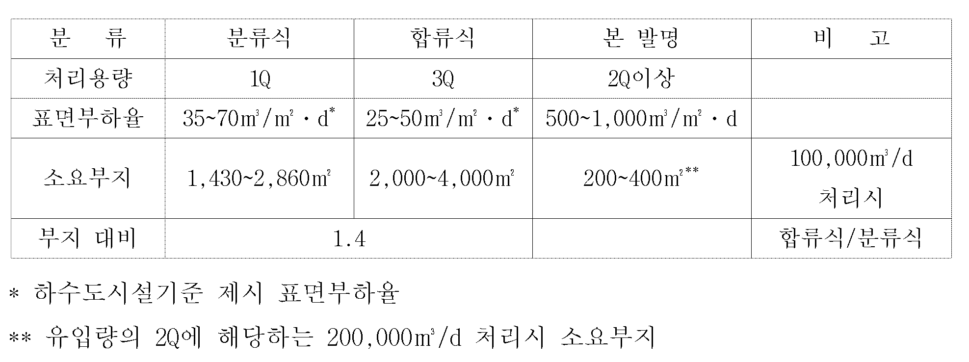
위의 표에서 보듯이 총하수량(3Q)중 후속처리공정에서 처리할수 있는 용량(1Q)은 기존의 일차침전지를 이용하여 사용하고, 용량을 초과하는 하수(2Q)는 본 고안의 처리시설을 사용하는 것으로 고려할 경우 기존 하수처리장 일차침전지의 40%에 해당하는 여유부지의 확보가 가능하며 이를 이용하여 시설의 설치 및 운전이 가능하게 된다.As shown in the table above, the capacity (1Q) of the total sewage (3Q) that can be treated in the subsequent treatment process is used by using the existing primary sedimentation battery, and the sewage (2Q) that exceeds the capacity is used in the treatment facility of the present invention. Considering this, it is possible to secure 40% of the existing sewage treatment plant primary sedimentation battery, and use it to install and operate the facility.
또한, 상기한 목적을 달성하기 위한 본 발명에 따른 월류수 처리장치는 합류식 하수도의 월류수에 포함된 오염물질을 처리하는 하수처리공정에 있어서, 후속 하수처리공정의 처리 용량(1Q)을 넘는 월류수를 유입하는 유입부와, 상기 유입부가 하부에 연결되어 유입되는 월류수를 상향류로 여과처리하는 처리조와, 상기 처리조의 하부에 설치되며 조대 협잡물을 여과하기 위한 침전여재를 갖는 하부 수처리부와, 상기 하부 수처리부의 상부에 마련되어 미세 이물질을 여과하기 위한 부상여재를 갖는 상부 수처리부와, 상기 상부 수처리부를 거쳐 여과된 월류수를 방류하는 방류부와, 상기 유입부로부터 원수를 유입하거나 방류부로부터 처리수를 유입하여 처리조의 내부를 세정하는 역세부를 포함한다.In addition, in the sewage treatment apparatus according to the present invention for achieving the above object in the sewage treatment process for treating contaminants contained in the overflow water of the combined sewage, inflow of the overflow water exceeding the treatment capacity (1Q) of the subsequent sewage treatment process And a lower water treatment unit having a treatment tank for filtering the overflow water flowing into the lower portion connected to the inlet and a lower flow, and a sedimentation media installed at the lower portion of the treatment tank to filter coarse contaminants, and the lower water treatment. An upper water treatment part provided at the upper part of the upper part and having a floating filter for filtering fine foreign matter, a discharge part for discharging the overflowed water filtered through the upper water treatment part, and inflowing raw water from the inlet part or inflowing the treated water from the discharge part; And a backwash for cleaning the interior of the treatment tank.
여기에서, 상기 역세부는 상기 유입부의 배관에 설치되어 유로의 방향을 전환하는 전동밸브와, 상기 처리조에 저장된 월류수를 교반시키는 교반부를 포함할 수 있다. 또한, 상기 교반부는 역세척을 원활하게 하기위해 상기 하부 수처리부 또는 상기 상부 수처리부의 하부에 공기를 주입하는 송풍기를 포함할 수 있다. 또한, 상기 교반부는 상기 하부 수처리부 또는 상기 상부 수처리부의 하부로 원수를 고압으로 분사하는 펌프를 포함할 수 있다. 더불어, 상기 하부 수처리부의 침전여재는 비중이 물보다 큰 것을 특징으로 하고, 상기 침전여재의 하부에는 상기 침전여재를 지지하는 하부 지지판이 설치될 수 있다. 또한, 상기 상부 수처리부의 부상여재는 비중이 물과 같거나 가벼운 것을 특징으로 하고, 상기 부상여재의 상부에는 상기 부상여재의 부상유출을 차단하는 상부 지지판이 설치될 수 있다. 아울러, 상기 유입부에는 상기 처리조의 오염물질의 포집량의 증가에 따라 증가되는 유입수의 압력손실을 감지하는 감지센서와, 상기 감지센서에 감지된 압력손실이 설정치에 도달할 경우, 상기 처리조로 공급되는 원수의 공급을 중단하도록 하는 상기 유입부의 전동밸브를 제어하는 제어부를 포함할 수 있다. 또한, 상기 제어부는 상기 감지센서에 감지된 압력손실이 설정치에 도달할 경우, 상기 역세부를 작동시켜 내부를 세정할 수 있다.Here, the backwash may include an electric valve installed in the pipe of the inlet to change the direction of the flow path, and a stirring part for stirring the overflow water stored in the treatment tank. In addition, the stirring unit may include a blower for injecting air to the lower portion of the lower water treatment unit or the upper water treatment unit to facilitate backwashing. In addition, the stirring unit may include a pump for spraying the raw water at a high pressure to the lower portion of the lower water treatment or the upper water treatment. In addition, the sedimentation media of the lower water treatment unit is characterized in that the specific gravity is greater than water, the lower support plate for supporting the sedimentation media may be installed in the lower portion of the precipitation media. In addition, the floating media of the upper water treatment unit is characterized in that the specific gravity is equal to or lighter than water, the upper support plate for blocking the outflow of the floating media may be installed on the upper portion of the floating media. In addition, the inlet unit is provided with a sensor for detecting the pressure loss of the influent water increases with the increase in the amount of contaminant of the treatment tank, and when the pressure loss detected by the sensor reaches a set value, it is supplied to the treatment tank It may include a control unit for controlling the electric valve of the inlet to stop the supply of raw water. In addition, when the pressure loss detected by the sensor reaches a set value, the controller may clean the interior by operating the backwashing unit.
또한, 상기한 목적을 달성하기 위한 본 발명에 따른 부상여재의 제조방법은 합류식 하수도의 월류수에 포함된 오염물질을 처리하는 월류수 처리장치에 사용되는 부상여재의 제조방법으로, 저발포재 시트를 마련하는 단계와, 성형하고자 하는 부상여재의 형태를 갖는 금형을 제조하는 단계와, 상기 금형으로 상기 저발포재 시트를 성형하는 단계를 포함한다.In addition, the method of manufacturing a floating filter according to the present invention for achieving the above object is a method of manufacturing a floating filter used in the overflow water treatment apparatus for treating the contaminants contained in the overflow water of the combined sewer, to provide a low foaming material sheet And forming a mold having a shape of a floating filter to be molded, and molding the low-foaming sheet into the mold.
또한, 상기 저발포재 시트는 폴리에틸렌, 폴리프로필렌, 폴리스틸렌, 에틸린초산비닐 중 어느 하나로 이루어질 수 있다. 또한, 상기 저발포재 시트는 2 내지 10mm의 두께를 갖는 판형태로 이루어진 것이 바람직하다. 또한, 상기 저발포재 시트는 압출 및 사출성형하여 내부에 다수의 독립적인 기포와 표면에 돌기가 형성될 수 있다.In addition, the low-foaming sheet may be made of any one of polyethylene, polypropylene, polystyrene, vinyl acetate. In addition, the low foaming sheet is preferably made of a plate shape having a thickness of 2 to 10mm. In addition, the low-foaming sheet may be formed by extrusion and injection molding a plurality of independent bubbles and projections on the surface.
전술된 바와 같이 구성된 본 발명에 따른 월류수처리장치 및 그에 사용되는 여재는 환경기초시설의 증설로 인해 하수처리율이 향상되면서 수계로 유입되는 점오염부하량이 감소함에 따라 강우시 주로 발생되는 강우유출수(비점오염물질) 및 합류식하수관거에서 강우에 의해 발생하는 합류식 하수도의 월류수에 의한 수계 영향은 증가되고 있어 이에 대한 시급한 대책이 요구되고 있으며 정부에서도 이에 대한 대책을 마련 중이다. 그러나 이를 뒷받침할 수 있는 기술이 전무한 현실에서 전술한 바와 같이 구성된 본 발명에 따른 월류수처리장치 및 그에 사용되는 여재는 수계로 유입되기 전 합류식 하수도의 월류수에 의한 부하를 삭감시킬 수 있으므로 하천, 호소의 수질을 개선시키는데 일조할 수 있다.The overflow water treatment apparatus and the media used therein according to the present invention configured as described above are mainly generated during rainfall due to the decrease in the point pollution load flowing into the water system as the sewage treatment rate is improved due to the expansion of the environmental foundation. Pollutants) and the impact of the water system caused by the overflow of the sewage from the combined sewage system caused by rainfall in the combined sewage pipes are urgently required, and the government is preparing a countermeasure. However, in the reality that there is no technology to support this, the overflow water treatment device and the media used therein according to the present invention configured as described above can reduce the load by the overflow water of the combined sewage before entering the water system. It can help improve water quality.
또한, 본 발명기술은 합류식 하수도의 월류수 뿐만 아니라 비강우시에는 하수처리공정에서 처리된 방류수를 다시 처리할 수도 있게 할 수 있어 계획 및 용도 에 따라 사용 용도를 무한하게 확장할 수 있다.In addition, the present invention can be able to reprocess not only the overflow water of the combined sewerage, but also the discharged water treated in the sewage treatment process in the case of rain, the use can be infinitely extended according to the plan and purpose.
현재 국내에는 합류식 하수도의 월류수의 방류수 허용 기준이 정립되어 있지 않으나 고도의 처리기준이 마련된다면 본 시스템 전단부에 응집제등을 투입함으로써 보다 양호한 방류수의 수질을 확보할 수 있다.At present, there is no established limit for the discharged water of monthly sewage from the combined sewage system, but if a high treatment standard is established, better quality of the discharged water can be secured by injecting a flocculant into the front end of the system.
또한 분류식 관거나 배수펌프장등에서 발생하는 방류수의 경우도 본 처리시설을 통하여 처리가 가능하므로 수생태계 보호를 위한 기본기술로 사용 시 수질개선에 미칠 영향은 지대할 것이다.In addition, the discharged water from the sorted pipe or drainage pumping station can be treated through this treatment facility, so the impact on water quality improvement will be great when used as a basic technology for protecting the water ecosystem.
이하, 본 발명의 실시예를 첨부된 도면을 참조하여 상세히 설명한다.Hereinafter, exemplary embodiments of the present invention will be described in detail with reference to the accompanying drawings.
도 2는 본 발명에 따른 월류수 처리장치를 간략하게 도시한 공정도이다.2 is a process diagram briefly showing the overflow water treatment apparatus according to the present invention.
본 발명에 따른 월류수 처리장치는, 도 2에 도시된 바와 같이, 하수를 취수하여 비부패성 무기물 및 입자가 큰 부유물질을 제거하는 침사지(110)와, 고형물입자를 침전, 제거하는 일차 침전지(120)를 갖는다. 또한, 상기 일차 침전지(120)에서 배출된 하수는 미생물에 의해 유기물질이 제거되는 포기조(130)와, 상기 포기조(130)를 거친 하수에 포함된 이물질을 최종적으로 침전시키는 이차 침전지(140)와, 상기 이차 침전지(140)를 거친 하수를 소독하여 방류하는 소독 및 방류조(150)를 포함한다. 또한, 상기 수처리장치는 상기 침사지(110)에 연결되어, 하수처리공정의 후속처리용량(1Q)을 초과하는 하수를 처리하는 월류수 처리장치(200)가 설치된다. 또한, 상기 월류수 처리장치(200)에서 처리된 하수는 별도의 소독 및 방류조(300)로 공급된 후 배출된다.The overflow water treatment apparatus according to the present invention, as shown in Figure 2, the
한편, 상기 수처리장치는 도 3에 도시된 바와 같이, 상기 침사지(110)와 상기 월류수 처리장치(200) 사이에 오염물질의 제거를 쉽게 하기 위해 오염물질을 응집시키는 응집제가 투입되는 응집제 투입조(310)가 마련될 수 있다.Meanwhile, as shown in FIG. 3, the water treatment device includes a flocculant injecting tank into which a flocculant agglomerates contaminants in order to facilitate removal of contaminants between the
도 4는 본 발명에 따른 월류수 처리장치를 간략하게 도시한 도이고, 도 5는 본 발명에 따른 월류수 처리장치가 정상적으로 월류수를 처리하는 경우 유량의 흐름을 도시한 도이다. 도 4와 도 5를 참고하면, 월류수 처리장치(200)는 합류식 하수도 월류수를 유입하기 위한 유입부(210)와, 상기 유입부(210)와 연결되어 하수를 여과처리하는 처리조(205)를 갖는다. 또한, 상기 월류수 처리장치(200)는 상기 처리조(205) 내에 마련되어 처리조내로 유입된 월류수중 조대협잡물을 처리하는 하부 수처리부(220)와, 상기 하부 수처리부(220)의 상층부에 마련되는 상부 수처리부(230)와, 상기 상부 수처리부(230)를 통해 여과된 월류수를 방류하는 방류부(240)와, 상기 하부 수처리부(220) 및 상기 상부 수처리부(230)를 세척하기 위한 역세부(250)를 포함한다.4 is a view schematically showing the overflow water treatment apparatus according to the present invention, Figure 5 is a view showing the flow of flow rate when the overflow water treatment apparatus according to the present invention normally processes the overflow water. 4 and 5, the overflow
또한, 상기 하부 수처리부(220) 또는 상기 상부 수처리부(230)에는 월류수에 포함된 오염물질을 포집하기 위한 여재(222, 232)가 채워진다.In addition, the lower
상기 유입부(210)는 상기 침사지(110)와 연결되어 있으며, 통상의 하수처리장의 후속처리공정에서 용량을 초과한 하수를 상기 처리조(205)로 유입시킨다. 이를 위해 상기 유입부(210)는 상기 침사지(110)에서 방류되는 하수를 상기 처리조(205)로 적정하게 분배하기 위한 분배부(212)가 설치된다.The
상기 분배부(212)는 상기 처리조(205)에 자연유하에 의한 상향류의 흐름이 이루어지도록 상기 처리조(205)의 하부로 하수를 공급하는 유입관(214)이 연결된다. 그리고, 상기 유입관(214)에는 전동밸브(214a)가 설치되어 역세나 청소 등의 유지관리가 필요시 유입을 제어할 수 있도록 한다. 또한, 상기 분배부(212)에는 필요시 역세수로 사용이 가능하도록 상부로부터 하수를 공급하는 역세수공급배관(216) 및 상기 역세수공급배관(216)의 제어를 위한 전동밸브(216a)가 설치된다. 상기 월류수 처리장치가 소정의 압력손실치에 도달하는 경우, 상기 유입관(214) 및 상기 역세수공급배관(216)에 설치된 전동밸브들(214a, 216a)을 제어하여 자동으로 역세를 수행하도록 제어된다.The
또한, 상기 하부 수처리부(220)는 상기 처리조(205)의 하부에 마련되며, 비중이 물보다 무거운 여재, 즉 침전여재(222)가 채워진다.In addition, the lower
상기 하부 수처리부(220)는 상기 침전여재(222)에 의해 비닐이나 잡석, 그릿(grit) 등의 비교적 조대한 협잡물의 포집이 이루어진다. 여기에서, 상기 침전여재(222)는 가능한 한 균일한 입경분포를 갖도록 구성하며, 입경이 약 2cm에서 5cm 정도로 이루어지는 것이 바람직하나 월류수의 유량 및 수질의 변동특성과 목표처리효율에 따라 5~10cm이상의 여재의 사용도 가능하다. 또한, 상기 침전여재(222)는 소정 유속에서도 부상하지 않을 정도의 비중으로 이루어질 수 있으며, 공급 및 조달이 용이한 쇄석이나 기타 침전성이 확보된 세라믹, 황토여재의 사용도 가능하다.The lower
한편, 상기 하부 수처리부(220)는 상기 처리조(205)의 하부에 상기 침전여재(222)를 지지하기 위한 하부 지지판(224)이 설치된다. 상기 하부 지지판(224)은 상기 침전여재(222)가 관통하지 않을 정도의 메쉬(mesh) 크기를 가지며, 바람직하게는 상기 처리조(205)의 하부로 유입된 협잡물이 상기 하부 지지판(224)에 부착되거나 걸려 상기 메쉬(mesh)의 구멍이 막히지 않을 정도의 크기로 형성된다. 또한, 상기 하부 수처리부(220)는 상기 처리조(205)로 유입되는 원수가 상기 처리조(205)의 일부에 집중되지 않도록 상기 유입관(214)의 단부에 원수의 배출을 분산시키는 분산관(218)이 설치된다.On the other hand, the lower
이와 같이, 상기 하부 수처리부(220)를 통과하여 1차적으로 조대 협잡물이 제거된 원수는 상부 수처리부(230)에 의해 2차적인 수처리가 이루어진다.As such, raw water from which coarse contaminants are first removed through the lower
상기 상부 수처리부(230)는 비중이 물보다 같거나 작은 여재, 즉 부상여재(232)가 채워진다. 이러한 부상여재는 독립기포가 발포되어 다수의 공극이 형성되며, 표면에 형성된 공극과 내부의 공극이 서로 연통하지 않는 것이 바람직하다.The upper
상기 상부 수처리부(230)는 상기 하부 수처리부(220)를 통과한 하수에 포함된 미세한 부유물질(SS : Suspended Solids)과 생물학적 산소 요구량(BOD : Biochemical Oxygen Demand)을 많이 필요로 하는 오염물질을 포집하도록 구성된다. 또한, 상기 부상여재(232)는 형상이나 구경이 균일하게 형성되는 것이 바람직하나, 각각의 부상여재(232) 사이에 형성되는 공간이 직선상으로 형성되거나, 규칙적이지 않도록 배치될 수 있다. 이와 같이, 부상여재(232) 사이의 형성이 불규칙적으로 형성될 경우, 오염물질과의 접촉면적이 증가되어 오염물질의 포집 효율을 높일 수 있다.The upper
상기 부상여재(232)는 원활한 부상이 가능하고 재료의 수급이 용이하도록 국 내 시장에서 범용으로 유통되는 독립기포 저발포재 시트를 이용할 수 있다. 여기에서, 상기 저발포재 시트는 저발포 폴리에틸렌(PE : polyethylene), 폴리프로필렌(PP : polypropylene), 폴리스틸렌(PS : polystyrene), 에틸린초산비닐(EVA : Ethylene Vinyl Acetate) 등의 재질로 이루어질 수 있다. 또한, 상기 부상여재(232)는 흡수율이 1% 이내로 장기간 수중에 침적된 상태에서도 자체의 부력유지가 가능하며 또한 저렴하고 손쉽게 제작, 공급이 용이하다. 이와 같이, 저발포되어 형성된 부상여재는 충분한 강도와 물성을 갖고 있으며, 재활용 제품의 사용이 가능하기 때문에 폐자재의 재이용 등 자원 순환형 재료의 선택이 가능하다.The floating
아래의 표 5는 부상여재로 사용되는 재료들의 물성값을 나타낸 표이다.Table 5 below shows the physical property values of the materials used as the flotation media.

이러한 요구 조건을 만족시키는 재료들 중 일반적으로 사용되는 재질의 특징은 다음과 같다.Among the materials satisfying these requirements, the characteristics of materials generally used are as follows.
폴리에틸렌(PE) 수지는 현재 세계에서 가장 많이 보급된 합성 고분자 물질로서 가격이 경제적이며 고속 가공성, 내응력, 신장율, 충격강도, 내열성, 난연성, 내약품성, 내부식성 등이 우수하여 폴리에틸렌수지로 여재를 제조시 가공이 용이하며 압축성이 우수하여 내부압밀에 변형이 일어나지 않으며 고농도의 하수에 대응할 수 있는 내구성을 가지게 된다. Polyethylene (PE) resin is the most widely used synthetic polymer material in the world at present, and it is economical in price, and it has high speed processability, stress resistance, elongation rate, impact strength, heat resistance, flame retardancy, chemical resistance, and corrosion resistance. It is easy to process during manufacturing and has excellent compressibility so that there is no deformation in internal consolidation and durability to cope with high concentration of sewage.
폴리프로필렌(PP) 수지는 흡수율과 비중이 매우 낮지만 구성분자가 탄화수소로만 이루어져 있으므로 극성이 없어 소수성이 크고 극성오염물질에 대한 저항성이 매우 높고, 폴리프로필렌은 폴리에틸렌과 비슷한 성질을 가지고 있다.Polypropylene (PP) resin has a very low absorption rate and specific gravity, but since the constituent molecules consist only of hydrocarbons, it has no polarity and thus has high resistance to polar pollutants. Polypropylene has properties similar to polyethylene.
폴리스티렌(PS)수지는 내충격성, 내열성, 내마모성, 착색성과 성형성이 우수하고 경제적이지만 화학용제에 잘 녹는다는 단점을 가지고 있다.Polystyrene (PS) resins are excellent in impact resistance, heat resistance, abrasion resistance, coloring and moldability and economical, but have a disadvantage of being soluble in chemical solvents.
에틸렌초산비닐(EVA) 수지는 투명하고 무독성이며 유연하여 저온에서는 견고하지 못하나 충격강도가 크며 특히 인열강도, 내스트레스 크랙성, 내오존성이 양호하여 내구성이 좋은 성질을 가지고 있다.Ethylene vinyl acetate (EVA) resin is transparent, non-toxic and flexible, so it is not strong at low temperatures, but has a high impact strength, and especially has good tear strength, stress crack resistance, and ozone resistance.
특히 저발포 재질 중 독립기포 발포재로써 그 발포도가 2~10배 정도의 재료가 본 고안에 가장 적합하며 이는 이러한 재료의 겉보기 비중이 0.1~0.5정도로 수중에서 적당한 부력에 의해 여재의 조밀한 충진층을 형성하고 그 사이의 공간에 오염물질을 포집할 수 있도록 하는 것이 가능하다.In particular, the low-foaming foam is a foam material of 2 to 10 times the most suitable for the present invention, which has an apparent specific gravity of about 0.1 to 0.5, and the compact filling of media by appropriate buoyancy in water It is possible to form layers and to collect contaminants in the spaces between them.
또한, 상기 상부 수처리부(230)에는 상기 부상여재(232)의 부상을 단속하기 위한 상부 지지판(234)이 설치된다. 상기 상부 지지판(234)은 상기 부상여재(232)가 관통하지 않을 정도의 메쉬(mesh) 크기를 갖도록 형성된다.In addition, the upper
한편, 상기 부상여재(232)와 침전여재(222)는 오염물질의 포집량이 증가할수록 하수의 통과시 발생하는 저항이 증가되어 압력손실이 발생한다. 이와 같이 상기 부상여재(232)와 침전여재(222)에 작용하는 압력손실은 유입관(214)에 걸리는 압력을 통해 알 수 있으며, 상기 부상여재(232)와 침전여재(222)에 의한 압력손실이 소정의 압력치에 도달하면 자동으로, 상기 유입관(214) 및 상기 역세수공급배관(216)에 설치된 전동밸브(214a, 216a)들을 조정하여 역세가 자동으로 이루어지도록 한다. 이를 위해, 상기 유입관(214) 및 상기 역세수공급배관(216)에 설치된 전동밸브(214a, 216a)들은 후술되는 제어부에 의해 개폐가 자동으로 제어될 수 있다. 또한, 상기 유입관(214)에는 상기 부상여재(232)와 침전여재(222)에 의한 압력손실을 감지하는 (도시되지 않은) 감지센서가 부착되고, 상기 감지센서에 감지된 압력손실이 설정치에 도달할 경우, 상기 처리조(205)로 공급되는 원수의 공급이 중단되도록 상기 유입관(214) 및 상기 역세수공급배관(216)에 설치된 전동밸브(214a, 216a)를 제어하는 제어부가 설치된다.On the other hand, the
또한, 상기 월류수 처리장치(200)는 상기 부상여재(232)와 침전여재(222)에 의한 압력손실값이 일정치 이하로 떨어지면 역세를 중단하도록 하거나 설정한 시간후 역세를 중단하도록 설정할 수 있다.In addition, the overflow
또한, 상기 방류부(240)는 상기 상부 수처리부(230)에서 처리된 하수를 방류관을 통해 소독 및 방류조로 배출한다.In addition, the
상기 방류부(240)는 상기 처리조(205)의 상부 수위를 유지하기 위한 방류관을 포함하며, 상기 방류관에는 전동밸브가 설치된다. 상기 방류관은 수처리된 하수를 상기 소독 및 방류조로 내보내는 제1방류관(242)과, 역세완료후 일정시간 처리조(205)내에 잔류하는 미처리 하수를 재처리하기위하여 계외로 배출하기 위한 제2방류관(244)으로 이루어진다.The
또한 상기 제1방류관(242)과 상기 제2방류관(244)에는 각각 전동밸브가 설치된다.In addition, the
본 발명에 따른 월류수 처리장치의 역세공정시 운전상태를 도시한 도인 도 6을 참고하면, 상기 역세부(250)는 상기 상부 및 하부 수처리부에서 소정의 압력손실이 발생하거나 일정시간이 경과한 경우에는 역세를 실시한다. 이와 같이, 상기 역세부(250)에 의한 역세공정의 주기는 유입수의 농도 및 유량 등에 영향을 받게 되므로 시설 설치 후 시운전시 충분한 자료를 수집하여 현장에 맞는 운전방법을 채택하거나 PID제어 등을 통하여 현장 실정에 맞추어 가도록 시스템을 구성할 수도 있다.Referring to FIG. 6, which illustrates an operating state during a backwashing process of the overflow water treatment apparatus according to the present invention, the
상기 역세부(250)는 상기 하부 수처리부(220) 및 상기 상부 수처리부(230)에 각각의 역세용 배관(254)을 설치하거나 하부 수처리부 아랫부분만 역세용 배관(254)을 설치할 수 있으며, 상기 역세부(250)는 상기 처리조(205)의 내부에 저장된 하수를 교반하는 교반부를 더 포함한다. 여기에서, 상기 교반부는 송풍기(252)를 이용하여 공기를 주입하거나 펌프를 설치하여 처리수를 이용할 수 있으며 이를 혼용하여 사용이 가능하도록 구성하는 것도 가능하다. 또한, 상기 교반부는 교반 효율의 증가를 위해 상기 역세용 배관(254)의 단부에 노즐(255)이 설치된다.The
또한, 상기 역세부(250)는 상기 처리조(205)의 하부에 설치된 역세수 배출관(256)을 통해 포집된 협잡물이 우선 배출되도록 소량을 배제시킨 후, 상기 역세부(250)에 의한 교반을 실시하여 포집된 협잡물을 탈리하여 상기 역세수 배출관(256)을 통해 배출한다. 이때, 상기 역세수 배출관(256)을 통해 배출되는 배출수는 기존의 일차 침전지(120)로 송수하거나 별도의 저장시설로 보내어 처리가 되도록 구성할 수 있다. 또한, 역세수 배출에 의하여 소실된 유량은 별도로 마련된 처리수 저장조나 상기 유입부(210)에 설치된 역세수공급배관(216)으로부터 유입수를 보충하여 충분한 역세를 수행한다.In addition, the
한편, 본발명에서 사용되는 여재는 그 형태가 제한되지 않으며, 포집율을 향상시키기 위해 다양한 형태로 변형될 수 있다. 일례로, 상기 부상여재는, 도 7과 같이, 발포도에 따라 각각의 고유한 겉보기 비중이 만들어지며, 이를 상기 처리조(205) 내부에 충진할 경우 각 비중에 의해 부상속도가 다르게 형성된다.On the other hand, the media used in the present invention is not limited in form, and may be modified in various forms to improve the collection rate. For example, the flotation media, as shown in Figure 7, each of the apparent apparent specific gravity is made according to the degree of foaming, when filling the inside of the
도 7은 본 발명에 따른 수처리장치의 월류수 처리장치의 부상여재를 도시한 도이다. 도 7을 참고하면, 상기 처리조(205)에 저장된 부상여재(232)가 2중, 3중의 층을 이루도록 형성할 수 있다. 그리고, 이 경우 비중이 가장 가벼운 여재는 소형이(232a) 되게 하고 중간정도의 비중의 여재는 중형(232b), 가장 무거운 여재의 경우 대형(232c)이 되도록 구성함으로써 상향류의 흐름이 형성되었을 경우 하부 층에서는 큰 부유입자를 중층에서는 작은 입자, 그리고 상층에서는 미세입자를 포집하게 되어 여재의 포집량을 최대화 하는 것이 가능해지며, 포집량 대비 역세시간을 장기간으로 유지가 가능하게 된다.7 is a view showing the floating media of the overflow water treatment apparatus of the water treatment apparatus according to the present invention. Referring to FIG. 7, the
상기 부상여재(232)의 제조방법을 도 8을 참고하여 설명하면, 원재료를 마련(S11)하고, 독립기포 저발포재 시트를 마련하는 단계(S12)와, 성형하고자 하는 부상여재의 형태를 갖는 금형을 제조하는 단계(S13)와, 상기 금형으로 상기 저발포재 시트를 가공, 성형하는 단계(S14)를 포함한다.The manufacturing method of the
보다 상세하게는, 범용 독립기포 저발포시트를 마련한다. 이러한 독립기포 저발포시트는 두께 2~10mm정도이며, 이를 이용하여 소정의 형상을 갖도록 제작된 금형을 이용하여 가공, 성형함으로써 생산이 완료된다. 가공 및 성형단계는 재료의 특성과 생산성에 따라 압출 및 사출성형이 가능하나 일반적으로 압출성형에 의한 가공방법을 사용하도록 한다.More specifically, a general independent foam low foam sheet is provided. The low-foam foam sheet is about 2 ~ 10mm thick, the production is completed by processing, molding using a mold manufactured to have a predetermined shape using this. In the processing and molding step, extrusion and injection molding are possible according to the properties and productivity of the material.
더불어, 본 발명의 수처리장치에 사용되는 여재의 형상은, 도 9에 도시된 바와 같이, 역세시 자체에 회전이 용이한 구조가 되도록 함으로써 순간적인 역세가 이루어지게 하여 역세시간의 단축이 가능한 구조로 적용하였으며 시설의 설비들은 처리조(205)내 여재에 포집된 부유물질을 탈리해 낼 수 있도록 충분한 교반력이 갖추어 지도록 구성하며 부상여재부의 역세부는 측면 역세가 이루어지도록 하면 여재의 교반이 용이해 효율이 더욱 높아지게 할 수 있다. 또한 시판되는 여재 중 상기의 기능을 갖춘 여재의 사용도 가능하며 특정물질에 대한 처리 효율을 향상시키기 위해서는 여재의 표면을 코팅하여 사용하는 것도 가능할 것이다.In addition, the shape of the filter medium used in the water treatment apparatus of the present invention, as shown in Figure 9, by the structure that can be easily rotated in the backwashing itself is instantaneous backwashing to achieve a structure capable of shortening the backwashing time The facilities of the facility are configured to have sufficient agitation power to detach the suspended matter collected in the media in the
이상과 같이 본 발명에 따른 수처리장치의 월류수 처리장치와, 그에 사용되는 부상여재의 제조방법 및 부상여재를 예시된 도면을 참조로 설명하였으나, 본 발명은 이상에서 설명된 실시예와 도면에 의해 한정되지 않으며, 특허청구범위 내에서 본 발명이 속하는 기술분야에서 통상의 지식을 가진 자들에 의해 다양한 수정 및 변형될 수 있음은 물론이다.As described above with reference to the illustrated drawings of the overflow water treatment apparatus of the water treatment apparatus according to the present invention, the manufacturing method and the flotation filter used therein, the present invention is limited by the embodiments and drawings described above Of course, various modifications and variations can be made by those skilled in the art within the scope of the claims.
도 1은 일반적인 하수처리공정을 간략하게 도시한 공정도.1 is a process diagram briefly showing a general sewage treatment process.
도 2는 본 발명에 따른 공정적용시 히수처리공정을 간략하게 도시한 공정도.Figure 2 is a process chart briefly showing the hydrothermal treatment process when applying the process according to the present invention.
도 3은 본 발명에 다른 실시예에 따른 공정적용시 히수처리공정을 간략하게 도시한 공정도.Figure 3 is a process diagram briefly showing the hydrothermal treatment process when applying the process according to another embodiment of the present invention.
도 4는 본 발명에 따른 월류수 처리장치를 간략하게 도시한 도.Figure 4 is a simplified view of the overflow water treatment apparatus according to the present invention.
도 5는 본 발명에 따른 월류수 처리장치가 정상적으로 월류수를 처리하는 경우 유량의 흐름을 도시한 도.Figure 5 is a view showing the flow of the flow rate when the overflow water treatment apparatus according to the present invention normally processes the overflow water.
도 6은 본 발명에 따른 월류수 처리장치의 역세공정시의 운전상태를 도시한 도.6 is a view showing an operating state during the backwashing process of the overflow water treatment apparatus according to the present invention.
도 7은 본 발명에 따른 월류수 처리장치의 부상여재를 도시한 도.7 is a view showing the flotation media of the overflow water treatment apparatus according to the present invention.
도 8은 본 발명에 따른 월류수 처리장치에 사용되는 부상여재의 제조방법을 도시한 순서도.8 is a flow chart showing a method of manufacturing a flotation filter used in the overflow water treatment apparatus according to the present invention.
도 9의 (a) 내지 (f)는 본 발명의 실시예에 따른 부상여재를 도시한 도.9 (a) to (f) is a view showing the flotation filter according to an embodiment of the present invention.
Claims (13)
Priority Applications (1)
| Application Number | Priority Date | Filing Date | Title |
|---|---|---|---|
| KR1020070139203A KR100951135B1 (en) | 2007-12-27 | 2007-12-27 | Overflow water treatment apparatus of confluent water drainage, manufacturing mathod of float media and float media |
Applications Claiming Priority (1)
| Application Number | Priority Date | Filing Date | Title |
|---|---|---|---|
| KR1020070139203A KR100951135B1 (en) | 2007-12-27 | 2007-12-27 | Overflow water treatment apparatus of confluent water drainage, manufacturing mathod of float media and float media |
Publications (2)
| Publication Number | Publication Date |
|---|---|
| KR20090071017A KR20090071017A (en) | 2009-07-01 |
| KR100951135B1 true KR100951135B1 (en) | 2010-04-07 |
Family
ID=41322483
Family Applications (1)
| Application Number | Title | Priority Date | Filing Date |
|---|---|---|---|
| KR1020070139203A KR100951135B1 (en) | 2007-12-27 | 2007-12-27 | Overflow water treatment apparatus of confluent water drainage, manufacturing mathod of float media and float media |
Country Status (1)
| Country | Link |
|---|---|
| KR (1) | KR100951135B1 (en) |
Cited By (7)
| Publication number | Priority date | Publication date | Assignee | Title |
|---|---|---|---|---|
| KR100978070B1 (en) | 2010-06-18 | 2010-08-26 | 미라클워터 주식회사 | Filtraion apparatus having ss filtering type and backwash-water discharge type |
| KR100978071B1 (en) | 2010-06-18 | 2010-08-26 | 미라클워터 주식회사 | Filtraion apparatus having ss filtering type and backwash-water discharge type |
| KR101104082B1 (en) * | 2011-07-15 | 2012-01-11 | 코오롱워터텍 주식회사 | Apparatus for filtering rainwater |
| KR101130132B1 (en) * | 2011-03-15 | 2012-03-28 | 신강하이텍(주) | System for treating total phosphorus from effluent water of sewage treatment plant during the dry season and treating combined sewer overflow selectively during rainy day |
| KR101248394B1 (en) | 2011-12-14 | 2013-04-01 | 주식회사 신우엔지니어링 | Overflow water treatment apparatus of confluent water drainage |
| KR101299717B1 (en) * | 2013-06-04 | 2013-09-10 | 코오롱워터앤에너지 주식회사 | Continuous washing and filtering apparatus using eva floating media |
| KR101384333B1 (en) | 2012-08-30 | 2014-04-10 | (주) 영동엔지니어링 | Suspended solids exclusion device |
Families Citing this family (5)
| Publication number | Priority date | Publication date | Assignee | Title |
|---|---|---|---|---|
| KR200454816Y1 (en) * | 2010-06-04 | 2011-07-28 | 미라클워터 주식회사 | Filtration apparatus for overflow of sewer |
| KR101631385B1 (en) * | 2014-11-21 | 2016-06-24 | (주) 에덴 | Filtration Method of Suspended Solids in the Wastewater Effluent by Compressive Forces of the Pressure of Water and Filtration System |
| KR101633767B1 (en) * | 2015-08-28 | 2016-07-08 | 주식회사 한국종합환경 | A upflow type stormwater treatment facilities using float filter media |
| KR102063343B1 (en) * | 2019-06-10 | 2020-01-07 | 주식회사 파이닉스알엔디 | Sedimentation and filtration apparatus using chemical coagulation |
| KR102327148B1 (en) * | 2019-09-02 | 2021-11-16 | 경기대학교 산학협력단 | Separation filter |
Citations (3)
| Publication number | Priority date | Publication date | Assignee | Title |
|---|---|---|---|---|
| JPH07171587A (en) * | 1993-12-20 | 1995-07-11 | Ebara Res Co Ltd | Method and apparatus for treating organic sewage |
| KR100248940B1 (en) * | 1997-02-10 | 2000-03-15 | 민병목 | Microbial contact filtration agent for wastewater purifying treatment and its preparation method |
| KR200339212Y1 (en) | 2003-10-14 | 2004-01-24 | 한창수기 주식회사 | Multi Media Upflow Filtering System for Nitrification, Denitrification and Suspended Solids Removal |
-
2007
- 2007-12-27 KR KR1020070139203A patent/KR100951135B1/en not_active IP Right Cessation
Patent Citations (3)
| Publication number | Priority date | Publication date | Assignee | Title |
|---|---|---|---|---|
| JPH07171587A (en) * | 1993-12-20 | 1995-07-11 | Ebara Res Co Ltd | Method and apparatus for treating organic sewage |
| KR100248940B1 (en) * | 1997-02-10 | 2000-03-15 | 민병목 | Microbial contact filtration agent for wastewater purifying treatment and its preparation method |
| KR200339212Y1 (en) | 2003-10-14 | 2004-01-24 | 한창수기 주식회사 | Multi Media Upflow Filtering System for Nitrification, Denitrification and Suspended Solids Removal |
Cited By (7)
| Publication number | Priority date | Publication date | Assignee | Title |
|---|---|---|---|---|
| KR100978070B1 (en) | 2010-06-18 | 2010-08-26 | 미라클워터 주식회사 | Filtraion apparatus having ss filtering type and backwash-water discharge type |
| KR100978071B1 (en) | 2010-06-18 | 2010-08-26 | 미라클워터 주식회사 | Filtraion apparatus having ss filtering type and backwash-water discharge type |
| KR101130132B1 (en) * | 2011-03-15 | 2012-03-28 | 신강하이텍(주) | System for treating total phosphorus from effluent water of sewage treatment plant during the dry season and treating combined sewer overflow selectively during rainy day |
| KR101104082B1 (en) * | 2011-07-15 | 2012-01-11 | 코오롱워터텍 주식회사 | Apparatus for filtering rainwater |
| KR101248394B1 (en) | 2011-12-14 | 2013-04-01 | 주식회사 신우엔지니어링 | Overflow water treatment apparatus of confluent water drainage |
| KR101384333B1 (en) | 2012-08-30 | 2014-04-10 | (주) 영동엔지니어링 | Suspended solids exclusion device |
| KR101299717B1 (en) * | 2013-06-04 | 2013-09-10 | 코오롱워터앤에너지 주식회사 | Continuous washing and filtering apparatus using eva floating media |
Also Published As
| Publication number | Publication date |
|---|---|
| KR20090071017A (en) | 2009-07-01 |
Similar Documents
| Publication | Publication Date | Title |
|---|---|---|
| KR100951135B1 (en) | Overflow water treatment apparatus of confluent water drainage, manufacturing mathod of float media and float media | |
| KR101696189B1 (en) | Apparatus for treating rainwater and overflow water of confluent water drainage | |
| KR100860079B1 (en) | A upward flow type filter and backwash method and the appratus for water treater | |
| KR100978070B1 (en) | Filtraion apparatus having ss filtering type and backwash-water discharge type | |
| CN102574031A (en) | High speed filtration device using porous media, and backwash method thereof | |
| US20160221853A1 (en) | Water clarification and sludge dewatering systems | |
| Ding | Wastewater treatment and reuse-The future source of water supply | |
| JP2004510566A (en) | Method and apparatus for treating wastewater | |
| KR101261839B1 (en) | Treatment system for side stream | |
| US20180170769A1 (en) | Method for processing waste water | |
| US9856161B2 (en) | Wastewater treatment apparatus capable of performing both initial rainwater overflow treatment and primary treatment, and wastewater treatment method according to said apparatus | |
| EP2707334B1 (en) | Biological treatment process and installation including air-lift and post-treatment in filter | |
| KR101779591B1 (en) | Recycle system based on multiple water treatment | |
| US20160288022A1 (en) | System for processing waste water | |
| KR100988316B1 (en) | Filtration apparatus for controlling a discharge of backwash water | |
| KR102253591B1 (en) | Non-point pollution reducing system having inproved backwash performance | |
| KR100446141B1 (en) | The waster water treatment system and method | |
| Tuluk et al. | High-speed treatment of low strength domestic wastewater for irrigation water production in pilot-scale classical, moving bed and fixed bed hybrid MBRs | |
| KR101262194B1 (en) | Device for treating combined sewer overflows | |
| KR101037888B1 (en) | Hybrid wastewater treatment equipment with sedimentation, biological degradation, filtration, phosphorus removal and uv disinfection system in a reactor | |
| KR101248394B1 (en) | Overflow water treatment apparatus of confluent water drainage | |
| KR100975410B1 (en) | Filtration apparatus of sludge circulation type and backwash-water discharge type | |
| Chen et al. | Gravity filtration | |
| KR20120050775A (en) | Buoyant density changing filter | |
| KR100975144B1 (en) | Filtration apparatus for river water using porous media |
Legal Events
| Date | Code | Title | Description |
|---|---|---|---|
| A201 | Request for examination | ||
| E902 | Notification of reason for refusal | ||
| E701 | Decision to grant or registration of patent right | ||
| GRNT | Written decision to grant | ||
| FPAY | Annual fee payment |
Payment date: 20130109 Year of fee payment: 4 |
|
| FPAY | Annual fee payment |
Payment date: 20140312 Year of fee payment: 5 |
|
| LAPS | Lapse due to unpaid annual fee |