KR100851977B1 - Controlling Method and apparatus for User Interface of electronic machine using Virtual plane. - Google Patents
Controlling Method and apparatus for User Interface of electronic machine using Virtual plane. Download PDFInfo
- Publication number
- KR100851977B1 KR100851977B1 KR1020060114716A KR20060114716A KR100851977B1 KR 100851977 B1 KR100851977 B1 KR 100851977B1 KR 1020060114716 A KR1020060114716 A KR 1020060114716A KR 20060114716 A KR20060114716 A KR 20060114716A KR 100851977 B1 KR100851977 B1 KR 100851977B1
- Authority
- KR
- South Korea
- Prior art keywords
- virtual plane
- electronic device
- marker
- user interface
- displayed
- Prior art date
Links
Images


Classifications
-
- G—PHYSICS
- G06—COMPUTING; CALCULATING OR COUNTING
- G06F—ELECTRIC DIGITAL DATA PROCESSING
- G06F3/00—Input arrangements for transferring data to be processed into a form capable of being handled by the computer; Output arrangements for transferring data from processing unit to output unit, e.g. interface arrangements
- G06F3/01—Input arrangements or combined input and output arrangements for interaction between user and computer
- G06F3/048—Interaction techniques based on graphical user interfaces [GUI]
- G06F3/0481—Interaction techniques based on graphical user interfaces [GUI] based on specific properties of the displayed interaction object or a metaphor-based environment, e.g. interaction with desktop elements like windows or icons, or assisted by a cursor's changing behaviour or appearance
-
- G—PHYSICS
- G06—COMPUTING; CALCULATING OR COUNTING
- G06F—ELECTRIC DIGITAL DATA PROCESSING
- G06F3/00—Input arrangements for transferring data to be processed into a form capable of being handled by the computer; Output arrangements for transferring data from processing unit to output unit, e.g. interface arrangements
- G06F3/01—Input arrangements or combined input and output arrangements for interaction between user and computer
- G06F3/017—Gesture based interaction, e.g. based on a set of recognized hand gestures
-
- G—PHYSICS
- G06—COMPUTING; CALCULATING OR COUNTING
- G06F—ELECTRIC DIGITAL DATA PROCESSING
- G06F3/00—Input arrangements for transferring data to be processed into a form capable of being handled by the computer; Output arrangements for transferring data from processing unit to output unit, e.g. interface arrangements
- G06F3/01—Input arrangements or combined input and output arrangements for interaction between user and computer
- G06F3/03—Arrangements for converting the position or the displacement of a member into a coded form
- G06F3/0304—Detection arrangements using opto-electronic means
- G06F3/0325—Detection arrangements using opto-electronic means using a plurality of light emitters or reflectors or a plurality of detectors forming a reference frame from which to derive the orientation of the object, e.g. by triangulation or on the basis of reference deformation in the picked up image
-
- G—PHYSICS
- G06—COMPUTING; CALCULATING OR COUNTING
- G06F—ELECTRIC DIGITAL DATA PROCESSING
- G06F3/00—Input arrangements for transferring data to be processed into a form capable of being handled by the computer; Output arrangements for transferring data from processing unit to output unit, e.g. interface arrangements
- G06F3/01—Input arrangements or combined input and output arrangements for interaction between user and computer
- G06F3/048—Interaction techniques based on graphical user interfaces [GUI]
- G06F3/0481—Interaction techniques based on graphical user interfaces [GUI] based on specific properties of the displayed interaction object or a metaphor-based environment, e.g. interaction with desktop elements like windows or icons, or assisted by a cursor's changing behaviour or appearance
- G06F3/0482—Interaction with lists of selectable items, e.g. menus
-
- G—PHYSICS
- G06—COMPUTING; CALCULATING OR COUNTING
- G06F—ELECTRIC DIGITAL DATA PROCESSING
- G06F3/00—Input arrangements for transferring data to be processed into a form capable of being handled by the computer; Output arrangements for transferring data from processing unit to output unit, e.g. interface arrangements
- G06F3/01—Input arrangements or combined input and output arrangements for interaction between user and computer
- G06F3/048—Interaction techniques based on graphical user interfaces [GUI]
- G06F3/0484—Interaction techniques based on graphical user interfaces [GUI] for the control of specific functions or operations, e.g. selecting or manipulating an object, an image or a displayed text element, setting a parameter value or selecting a range
Abstract
본 발명은 공간 상의 특정 영역을 이용하여 전자 기기의 사용자 인터페이스를 제어하는 방법 및 장치에 관한 것으로, 제 1 촬상 장치의 영상 표시부 및 제 2 촬상 장치의 영상 표시부에 각각 표시되는 적어도 2 이상의 영상들의 위치로부터 검출한 상기 영상들 각각의 공간 좌표를 기초로 가상 평면을 초기화하고, 초기화한 가상 평면을 기준으로 소정의 영상으로 표시되는 마커의 위치를 결정하고, 상기 가상 평면에 대응하는 전자 기기의 영상 표시부의 상기 마커에 대응하는 위치에 상기 마커에 대응하는 스크린 포인터를 표시한 후, 상기 마커의 이동을 통해 상기 스크린 포인터가 표시된 위치에 대응하는 상기 전자 기기의 메뉴를 선택함으로써, 사용자의 위치에 제한 받지 않고, 사용자의 간단한 동작만으로 전자 기기의 사용자 인터페이스를 편리하게 제어할 수 있다. The present invention relates to a method and an apparatus for controlling a user interface of an electronic device using a specific area in a space, the position of at least two or more images respectively displayed on the image display unit of the first imaging device and the image display unit of the second imaging device Initializes a virtual plane based on spatial coordinates of each of the images detected from the image, determines a position of a marker displayed as a predetermined image based on the initialized virtual plane, and displays an image display unit of the electronic device corresponding to the virtual plane. After displaying the screen pointer corresponding to the marker at the position corresponding to the marker of, by selecting the menu of the electronic device corresponding to the position where the screen pointer is displayed through the movement of the marker, the position of the user is not restricted. The user interface of the electronic device can be conveniently Can be controlled.
Description
도 1은 본 발명에서 사용되는 주요 구성 요소의 의미 및 주요 구성 요소들의 기하학적인 관계들을 나타낸 도면이다.1 is a view showing the meaning of the main components used in the present invention and the geometric relationships of the main components.
도 2는 본 발명에서 사용되는 주요 구성 요소들의 위치를 보다 구체적으로 나타낸 도면이다. 2 is a view showing in more detail the location of the main components used in the present invention.
도 3은 본 발명의 바람직한 일실시예에 따라 가상 평면을 이용하여 전자 기기의 사용자 인터페이스를 제어하는 방법을 나타낸 흐름도이다. 3 is a flowchart illustrating a method of controlling a user interface of an electronic device using a virtual plane according to an exemplary embodiment of the present invention.
도 4a는 본 발명의 바람직한 일실시예에 따라 촬상 장치의 캘리브레이션의 수행 시 사용되는 체스보드를 나타낸 도면이다. 4A is a diagram illustrating a chess board used when performing calibration of an imaging apparatus according to an exemplary embodiment of the present invention.
도 4b는 본 발명의 바람직한 일실시예에 따라 촬상 장치의 캘리브레이션을 수행하는 단계를 구체적으로 나타낸 도면이다. FIG. 4B is a diagram illustrating in detail a step of performing calibration of the imaging apparatus according to an exemplary embodiment of the present invention.
도 5a는 본 발명의 가상 평면을 초기화하는 제 1 실시예에서 사용되는 체스보드를 나타낸 도면이다. Fig. 5A shows a chess board used in the first embodiment of initializing the virtual plane of the present invention.
도 5b는 본 발명의 가상 평면을 초기화하는 제 1 실시예에 따라 가상 평면을 초기화하는 방법을 나타낸 도면이다. 5B is a diagram illustrating a method of initializing a virtual plane according to the first embodiment of the present invention.
도 5c는 본 발명의 일실시예에 따라 도 2의 제 1 촬상 장치의 영상 표시부(530)에 표시된 체스보드의 영상을 나타낸 도면이다. 5C is a diagram illustrating an image of a chessboard displayed on the
도 5d는 본 발명의 일실시예에 따라 도 2의 제 2 촬상 장치의 영상 표시부(540)에 표시된 체스보드의 영상을 나타낸 도면이다. FIG. 5D is a diagram illustrating an image of a chessboard displayed on the
도 6a는 본 발명의 가상 평면을 초기화하는 제 2 실시예에서 이용되는 손의 제스처를 나타낸 도면이다. 6A is a diagram showing a gesture of a hand used in the second embodiment of initializing the virtual plane of the present invention.
도 6b는 본 발명의 가상 평면을 초기화하는 제 2 실시예에 의해 초기화된 가상 평면을 세계 좌표를 중심으로 나타낸 도면이다. 6B is a diagram illustrating a virtual plane initialized by a second embodiment of initializing a virtual plane of the present invention with respect to world coordinates.
도 6c는 본 발명의 가상 평면을 초기화하는 제 2 실시예에 의해 가상 평면을 초기화하는 과정을 나타낸 도면이다. 6C is a diagram illustrating a process of initializing a virtual plane according to a second embodiment of initializing a virtual plane of the present invention.
도 6d는 본 발명의 가상 평면을 초기화하는 제 2 실시예에 의해 생성된 가상평면의 좌표축의 방향을 나타낸 도면이다. 6D is a view showing the direction of the coordinate axis of the virtual plane generated by the second embodiment of initializing the virtual plane of the present invention.
도 6e는 본 발명의 가상 평면을 초기화하는 제 2 실시예에 의해 생성된 가상 평면의 크기를 나타낸 도면이다. 6E is a diagram showing the size of the virtual plane generated by the second embodiment of initializing the virtual plane of the present invention.
도 7a는 본 발명의 가상 평면을 초기화하는 제 3 실시예를 나타낸 도면이다. 7A is a diagram showing a third embodiment of initializing a virtual plane of the present invention.
도 7b는 본 발명의 가상 평면을 초기화하는 제 3 실시예에 의해 사용자의 위치를 추적하여 가상 평면을 초기화하는 방법을 나타낸 도면이다. 7B is a diagram illustrating a method of initializing a virtual plane by tracking a user's position according to a third embodiment of initializing the virtual plane of the present invention.
도 7c는 본 발명의 가상 평면을 초기화하는 제 3실시예에 따라 초기화된 가상 평면과 눈의 위치를 나타낸 도면이다. 7C is a diagram illustrating positions of the virtual plane and the eye initialized according to the third embodiment of initializing the virtual plane of the present invention.
도 8a는 본 발명의 마커를 검출하는 제 1 실시예를 나타낸 도면이다. Fig. 8A is a diagram showing a first embodiment of detecting the marker of the present invention.
도 8b는 본 발명의 마커를 검출하는 제 2 실시예를 나타낸 도면이다. Fig. 8B is a diagram showing a second embodiment of detecting the marker of the present invention.
도 8c는 본 발명의 마커를 검출하는 제 3 실시예를 나타낸 도면이다. 8C is a diagram showing a third embodiment of detecting the marker of the present invention.
도 9는 마커의 Z 좌표 값의 변화에 따라 가상 평면을 기준으로 하는 마커의 위치의 변화를 나타낸 도면이다. 9 is a view illustrating a change in the position of the marker with respect to the virtual plane according to the change of the Z coordinate value of the marker.
도 10은 스크린 포인터의 크기와 마커와의 위치 관계를 나타낸 도면이다. 10 is a diagram illustrating a positional relationship between a size of a screen pointer and a marker.
도 11은 전자 기기의 사용자 인터페이스를 제어하는데 사용되는 가상 평면을 수행하는 기능에 따라 그 영역을 구별하여 나타낸 도면이다. FIG. 11 is a diagram illustrating the regions according to a function of performing a virtual plane used to control a user interface of an electronic device.
도 12는 본 발명의 바람직한 일실시예에 따라, 마커가 가상 평면의 가상의 쓰기 영역에 존재하였을 때 표시되는 스크린 포인터의 아이콘을 나타낸 도면이다. FIG. 12 is a diagram illustrating an icon of a screen pointer displayed when a marker exists in a virtual writing area of a virtual plane according to an exemplary embodiment of the present invention.
도 13은 본 발명의 바람직한 일실시예에 따라 가상 평면의 가상 스크린 영역에 대응하여 전자 기기의 스크린에 표시되는 메뉴를 나타내는 도면이다. FIG. 13 illustrates a menu displayed on a screen of an electronic device corresponding to a virtual screen area of a virtual plane according to an exemplary embodiment of the present invention.
도 14a 내지 도 14c는 본 발명의 바람직한 일실시예서 전자 기기가 디지털 TV인 경우, 가상 평면의 가상 스크린 영역에 대응하여 디지털 TV의 스크린에 표시되는 메뉴를 나타낸 도면이다. 14A to 14C are diagrams illustrating menus displayed on a screen of a digital TV corresponding to a virtual screen area of a virtual plane when the electronic device is a digital TV according to an exemplary embodiment of the present invention.
도 15는 본 발명의 바람직한 일실시예에 따라 가상 평면의 가상 스크린 영역에 대응하는 메뉴 중의 하나인 소프트 키보드를 나타낸 도면이다. FIG. 15 illustrates a soft keyboard as one of menus corresponding to a virtual screen area of a virtual plane according to an exemplary embodiment of the present invention.
도 16a 및 16b는 가상 평면의 가상 쓰기 영역에 의해 전자 기기의 사용자 인터페이스를 제어하는 제 1 실시예를 나타낸 도면이다. 16A and 16B illustrate a first embodiment in which a user interface of an electronic device is controlled by a virtual writing area of a virtual plane.
도 17a 내지 17c는 본 발명의 가상 평면의 가상 쓰기 영역에 의해 전자 기기의 사용자 인터페이스를 제어하는 제 2 실시예를 나타낸 도면이다. 17A to 17C are diagrams illustrating a second embodiment in which a user interface of an electronic device is controlled by a virtual writing area of a virtual plane of the present invention.
도 18a 및 18b는 마커의 이동에 따라, 전자 기기의 사용자 인터페이스의 메뉴가 선택되는 것을 나타낸 제 1 실시예의 도면이다. 18A and 18B are diagrams of a first embodiment showing that a menu of a user interface of an electronic device is selected as the marker moves.
도 19는 마커의 이동에 따라, 전자 기기의 사용자 인터페이스의 메뉴가 선택되는 것을 나타낸 제 2 실시예의 도면이다. 19 is a diagram of a second embodiment showing that a menu of a user interface of an electronic device is selected as a marker moves.
도 20은 본 발명의 바람직한 일실시예에 따라 가상 평면을 이용하여 전자 기기의 사용자 인터페이스를 제어하는 장치를 나타낸 도면이다. 20 illustrates an apparatus for controlling a user interface of an electronic device using a virtual plane according to an exemplary embodiment of the present invention.
본 발명은 컴퓨터 비전(Computer Vision), 패턴 인식(Pattern recognition) 및 제스처 인식(Gesture recognition)과 같은 에이치시아이(Human Computer interaction, HCI)에 관한 것으로, 보다 상세하게는 가상 평면을 이용하여 전자 기기의 사용자 인터페이스(User Interface, UI)를 쉽게 제어할 수 있는 장치 및 방법에 관한 것이다. BACKGROUND OF THE
TV와 같은 전자 기기를 제어하기 위한 전통적인 방법은 리모콘을 사용하는 것이었다. 리모콘을 사용하여 전자 기기를 제어하는 방법은 매우 편리한 방법이지만, 전자 기기가 점차 복잡해짐에 따라 전자 기기를 제어하기 위한 리모콘의 버튼의 숫자도 비례하여 더 많이 요구되었다. 오늘날 일반적인 TV 리모콘은 대략 20개 정도의 버튼을 가지는데, 이러한 버튼의 각 기능을 기억하는 것은 다소 어려움이 있다. 게다가 DTV(Desktop Video)의 사용할 수 있는 기능들이 증가함에 따라 이들 을 제어하기 위한 콘트롤러의 공간이 충분하지 않게 되는 문제점이 있었다. Traditional methods for controlling electronic devices such as TVs have been using remote controls. The method of controlling the electronic device using the remote control is a very convenient method, but as the electronic device becomes more complicated, the number of buttons of the remote control for controlling the electronic device is also required in proportion. Today's average TV remote control has about 20 buttons, and remembering each function of these buttons is somewhat difficult. In addition, as the available functions of DTV (Desktop Video) increase, there is a problem that there is not enough space of a controller to control them.
이러한 문제점을 해결하기 위한 방안으로, 별도의 콘트롤러를 사용하지 않고 사용자의 동작만으로 쉽고 간편하게 전자 기기를 제어하는 여러 방법이 제안되었다. 이러한 방법 중의 하나로, 하나의 촬상 장치를 TV에 부착하고, TV에 부착된 촬상 장치에서 입력 이미지의 각 픽셀을 분류하는 방법을 이용하여 전자 기기를 제어하는 방법이 제안되었다. 그러나, 이러한 방법에서는 특정 영역에서만 사용자의 입력을 받을 수 있으므로, 사용자는 고정된 광선으로부터 멀리 떨어지지 못하는 문제점이 있었다, 즉, 사용자의 행동 반경이 제한되는 문제점이 있었다. 또한, 이러한 발명은 피부의 색에 기초하여 손을 검출하므로, 조명(Illumination)이 변화하면, 손을 정확히 검출하지 못하는 문제점이 있었다. 또한, 전자 기기를 제어하는 동작에 대해 각각 다른 사용자의 동작을 대응하여, 사용자는 많은 동작을 기억해야 하는 불편함이 있었다. 다른 방법으로 여러 개의 촬상 장치에 의해 손가락 끝(Finger tip)을 검출하고, 검출한 손가락 끝의 3차원의 위치에 의해 전자 기기를 제어하는 방법이 제안되었다. 그러나, 3개의 촬상 장치가 벽이나 천정과 같은 고정된 위치에 설치되어야 하므로, 촬상 장치의 설치에 불편함이 있었다. 또한, 손가락의 작은 움직임이라도 전자 기기의 스크린에는 크게 움직이므로 스크린의 아이콘을 제어하는데 많은 어려움이 있었다. 또한, 항상 고정된 위치에서만 사용이 가능하다는 문제점이 있었다. In order to solve this problem, various methods for easily and simply controlling an electronic device by a user's operation without using a separate controller have been proposed. As one of such methods, a method of controlling an electronic device using a method of attaching one imaging device to a TV and classifying each pixel of the input image in the imaging device attached to the TV has been proposed. However, in this method, since the user's input can be received only in a specific area, the user may not be far from the fixed beam, that is, the user's radius of action is limited. In addition, since the present invention detects a hand based on the color of the skin, there is a problem in that the hand cannot be accurately detected when illumination is changed. In addition, in response to operations of different users with respect to operations for controlling the electronic device, there is an inconvenience in that the user must remember many operations. Alternatively, a method of detecting a finger tip by several imaging devices and controlling the electronic device by the detected three-dimensional position of the finger tip has been proposed. However, since the three imaging devices must be installed at fixed positions such as walls or ceilings, there is an inconvenience in installing the imaging device. In addition, even if a small movement of the finger moves large on the screen of the electronic device, there was a lot of difficulty in controlling the icon of the screen. In addition, there was a problem that it can always be used only in a fixed position.
본 발명이 이루고자 하는 기술적 과제는 전자 기기의 사용자 인터페이 스(User Interface, UI)를 제어하는데 있어서, 사용자가 원하는 임의의 위치에 대해 입력을 받거나 또는 사용자의 위치에 따라 자동적으로 입력 영역이 설정되어, 사용자의 위치에 제한받지 않고 생성된 가상 평면을 이용하여 전자 기기의 사용자 인터페이스를 제어하는 방법 및 장치를 제공하는데 있다. The technical problem to be achieved by the present invention is to control the user interface (UI) of the electronic device, the user receives an input for any desired location or the input area is automatically set according to the user's location, The present invention provides a method and apparatus for controlling a user interface of an electronic device using a generated virtual plane without being limited by a user's location.
또한, 상기된 방법을 컴퓨터에서 실행시키기 위한 프로그램을 기록한 컴퓨터로 읽을 수 있는 기록 매체를 제공하는데 있다. Further, the present invention provides a computer-readable recording medium having recorded thereon a program for executing the above method on a computer.
본 발명의 기술적 과제들은 이상에서 언급한 기술적 과제로 제한되지 않으며, 언급되지 않은 또 다른 기술적 과제들은 아래의 기재로부터 본 발명이 속하는 기술 분야에서 통상의 지식을 가진 자에게 명확하게 이해될 수 있을 것이다. Technical problems of the present invention are not limited to the technical problems mentioned above, and other technical problems not mentioned will be clearly understood by those skilled in the art to which the present invention pertains. .
상기 문제점을 해결하기 위한 본 발명에 따른 가상 평면을 이용하여 전자 기기의 사용자 인터페이스를 제어하는 방법은 제 1 촬상 장치의 영상 표시부 및 제 2 촬상 장치의 영상 표시부에 각각 표시되는 적어도 2 이상의 영상들의 위치로부터 검출한 상기 영상들 각각의 공간 좌표를 기초로 가상 평면을 초기화하는 단계; 상기 가상 평면을 기준으로 소정의 영상으로 표시되는 마커의 위치를 결정하는 단계; 상기 가상 평면에 대응하는 전자 기기의 영상 표시부의 상기 마커에 대응하는 위치에 상기 마커에 대응하는 스크린 포인터를 표시하는 단계; 및 상기 마커의 이동을 통해 상기 스크린 포인터가 표시된 위치에 대응하는 상기 전자 기기의 메뉴를 선택하는 단계를 포함한다. Method for controlling the user interface of the electronic device using a virtual plane according to the present invention for solving the above problems is the position of at least two or more images respectively displayed on the image display unit of the first imaging device and the image display unit of the second imaging device; Initializing a virtual plane based on spatial coordinates of each of the images detected from the image; Determining a position of a marker displayed as a predetermined image based on the virtual plane; Displaying a screen pointer corresponding to the marker at a position corresponding to the marker of the image display unit of the electronic device corresponding to the virtual plane; And selecting a menu of the electronic device corresponding to the position where the screen pointer is displayed by moving the marker.
상기 또 다른 기술적 과제를 해결하기 위하여, 본 발명에 따른 가상 평면을 이용하여 전자 기기를 제어하는 방법을 컴퓨터에서 실행시키기 위한 프로그램을 기록한 컴퓨터로 읽을 수 있는 기록매체를 제공한다. In order to solve the above another technical problem, there is provided a computer-readable recording medium recording a program for executing a method for controlling an electronic device on a computer using a virtual plane according to the present invention.
상기 또 다른 기술적 과제를 해결하기 위하여, 본 발명에 따른 가상 평면을 이용하여 전자 기기의 사용자 인터페이스를 제어하는 장치는 영상을 촬상하는 제 1 촬상부 및 제 2 촬상부; 상기 제 1 촬상부 및 상기 제 2 촬상부의 영상의 촬상에 의해 상기 제 1 촬상부의 영상 표시부 및 상기 제 2 촬상부의 영상 표시부에 각각 표시되는 적어도 2 이상의 영상들의 위치로부터 검출한 상기 영상들 각각의 공간 좌표를 기초로 가상 평면을 초기화하는 가상 평면 초기화부; 상기 제 1 촬상부 및 상기 제 2 촬상부가 촬상한 소정의 영상으로부터 마커의 공간 상의 위치를 결정하고, 상기 마커의 공간상의 위치를 상기 가상 평면상의 위치로 대응시켜 상기 가상 평면상에서 마커의 위치를 결정하는 마커 위치 결정부; 및 상기 마커의 위치에 대응하여 전자 기기의 영상 표시부에 표시되는 스크린 포인터의 위치를 계산하고, 상기 마커의 이동에 대응하여 이동하는 상기 스크린 포인터가 표시된 위치에 대응하는 상기 전자 기기의 메뉴를 선택하는 연산 처리부를 포함한다. In order to solve the another technical problem, an apparatus for controlling a user interface of an electronic device using a virtual plane according to the present invention comprises: a first imaging unit and a second imaging unit for capturing an image; A space of each of the images detected from the positions of at least two or more images displayed on the image display unit of the first imaging unit and the image display unit of the second imaging unit, respectively, by imaging the images of the first and second imaging units; A virtual plane initialization unit for initializing the virtual plane based on the coordinates; The position of the marker is determined from the predetermined image captured by the first and second imaging units, and the position of the marker is determined on the virtual plane by matching the position of the marker with the position on the virtual plane. A marker position determiner; And calculating a position of the screen pointer displayed on the image display unit of the electronic device in response to the position of the marker, and selecting a menu of the electronic device corresponding to the position where the screen pointer moving in response to the movement of the marker is displayed. It includes an arithmetic processing unit.
이하에서는 도면을 참조하여 본 발명의 바람직한 실시예들을 상세히 설명한다.Hereinafter, exemplary embodiments of the present invention will be described in detail with reference to the accompanying drawings.
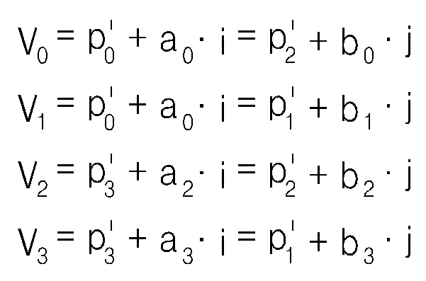
도 1은 본 발명에서 사용되는 주요 구성 요소의 의미 및 주요 구성 요소들의 기하학적인 관계들을 나타낸 도면이다. 100(X, Y, Z)는 세계 좌표(world coordinate)를 표시한 것이다. 세계 좌표는 컴퓨터 그래픽스(CG)에서 응용 프로그램 중에 도형 요소의 위치를 지정하는데 사용되는 좌표로 장치와 관계가 없는, 즉 장치 독립적인 데카르트 좌표(Cartesian coordinate)를 의미한다. 이러한, 세계 좌표는 공간상에 존재하는 특정 영상의 위치를 나타낼 때 사용한다. 110(x1, y1)은 본 발명에서 전자 기기의 정면에 위치한 영상이 제 1 촬상 장치의 영상 표시부에 표시되는 위치를 좌표로 나타낸 것이다. 120(x2, y2)은 본 발명에서 전자 기기의 정면에 위치한 영상이 제 2 촬상 장치의 영상 표시부에 표시되는 위치를 좌표로 나타낸 것이다. 본 발명에서 사용되는 촬상 장치는 렌즈를 통해 영상을 획득하고, 획득한 영상을 영상 표시부에 표시하는 장치를 의미하고, 이러한 촬상 장치로는 카메라가 일반적이나, 반드시 이에 한정되지는 않는다. 130(M)은 본 발명에서 사용되는 마커(marker)를 표시한 것으로, 마커는 공간 좌표에서의 위치인 131(Mw) 및 가상 평면에서의 위치인 132(Mv)로 표시된다. 140은 본 발명에서 사용되는 가상 평면(virtual plane)을 나타낸 것이다. 본 발명에서 사용되는 가상 평면이란, 전자 기기의 사용자 인터페이스(user interface)를 제어하기 위해 인터페이스(interface)의 역할을 수행하는 공간상의 가상적인 평면을 의미한다. 가상 평면은 세계 좌표에서 4개의 꼭지점 141(V0), 142(V1), 143(V2) 및 144(V3)으로 표시되며, (i, j, k)(145, 146, 147)은 세계 좌표에서 가상 평면의 좌표축을 나타낸 단위벡터(Unit vector)이다. 1 is a view showing the meaning of the main components used in the present invention and the geometric relationships of the main components. 100 (X, Y, Z) represents world coordinates. World coordinates are coordinates used in computer graphics (CG) to specify the position of a figure element in an application, meaning device-independent Cartesian coordinates. These world coordinates are used to indicate the position of a specific image existing in space. Reference numeral 110 (x1, y1) denotes coordinates of a position where an image located in front of the electronic device is displayed on the image display unit of the first imaging device. In the present invention, 120 (x2, y2) is a coordinate representing a position where an image located in front of the electronic device is displayed on the image display unit of the second imaging device. The imaging device used in the present invention refers to a device that acquires an image through a lens and displays the obtained image on an image display unit. A camera is generally used as the imaging device, but is not limited thereto. 130 (M) indicates a marker used in the present invention, and the marker is indicated by 131 (Mw), which is a position in spatial coordinates, and 132 (Mv), which is a position in a virtual plane. 140 shows a virtual plane used in the present invention. The virtual plane used in the present invention means a virtual plane in space that serves as an interface to control a user interface of the electronic device. The virtual plane is represented by four vertices 141 (V0), 142 (V1), 143 (V2), and 144 (V3) in world coordinates, and (i, j, k) (145, 146, 147) in world coordinates. Unit vector representing the coordinate axis of the virtual plane.
도 2는 본 발명에서 사용되는 주요 구성 요소들의 위치를 보다 구체적으로 나타낸 도면이다. 2 is a view showing in more detail the location of the main components used in the present invention.
TV(200)가 존재하면, 사용자(210)는 TV(200)의 정면에 위치하고, 가상 평면(220)은 사용자(210)와 TV(200) 사이에 위치한다. 가상 평면(220)에서 TV(200)의 사용자 인터페이스를 제어하기 위한 마커(230)는 가상 평면(220) 가까이에 위치한다. 또한, 가상 평면(220)의 초기화에 사용되는 제 1 촬상 장치(240) 및 제 2 촬상 장치(250)는 사용자를 촬상할 수 있는 영역이면 어느 곳에 위치하더라도 무방하다. If the
도 3은 본 발명의 바람직한 일실시예에 따라 가상 평면을 이용하여 전자 기기의 사용자 인터페이스를 제어하는 방법을 나타낸 흐름도이다. 3 is a flowchart illustrating a method of controlling a user interface of an electronic device using a virtual plane according to an exemplary embodiment of the present invention.
제 300 단계에서 제 1 촬상 장치 및 제 2 촬상 장치의 캘리브레이션(Calibration)을 수행한다. 촬상 장치의 캘리브레이션이란, 촬상 장치에서 촬상하여 영상 표시부에 표시되는 촬상된 영상 상에서의 위치와 화상의 실제 공간에서의 세계 좌표계에 의한 위치와의 관계를 정확히 결정하기 위하여, 촬상 장치의 내부 파라미터(intrinsic parameter) 및 외부 파라미터(extrinsic parameter)를 추정하는 것을 의미한다. 촬상 장치의 캘리브레이션이 완료되면, 촬상 장치의 영상 표시부의 위치만으로 영상의 공간 좌표를 검출할 수 있게 된다. 이러한 내부 파라미터에는 촬상 장치의 초점 거리(f) 및 프린시플 포인트(principal point, 광학축과 이미지 면과 교차점(cx, cy))가 있고, 외부 파라미터에는 좌표의 위치(t1, t2, t3) 및 3차원 회전 매트릭스(rij)가 있다. 본 발명의 바람직한 일실시예서는 내부 파라미터 및 외부 파라미터를 추정하기 위해서, 내부에 표시된 격자무늬가 상하 좌우 간격이 동일하게 배열된 체스보드(chess board)를 이용한다. In
도 4a는 본 발명의 바람직한 일실시예에 따라 촬상 장치의 캘리브레이션의 수행 시 사용되는 체스보드를 나타낸 도면이다. 본 발명의 바람직한 일실시예에서는 도 4a에서와 같이 8*6의 크기를 갖는 체스보드를 이용하였으나, 반드시 이에 한 정하지는 않는다. 4A is a diagram illustrating a chess board used when performing calibration of an imaging apparatus according to an exemplary embodiment of the present invention. In a preferred embodiment of the present invention used a chess board having a size of 8 * 6 as shown in Figure 4a, but is not necessarily limited thereto.
도 4b는 본 발명의 바람직한 일 실시예에 따라 촬상 장치의 캘리브레이션을 수행하는 단계를 구체적으로 나타낸 도면이다. 이하, 도 4b를 참조하여, 촬상 장치의 캘리브레이션을 수행하는 단계를 구체적으로 살펴본다. 4B is a diagram illustrating in detail a step of performing calibration of an imaging device according to an exemplary embodiment of the present invention. Hereinafter, referring to FIG. 4B, the steps of performing calibration of the imaging apparatus will be described in detail.
제 400 단계에서 체스보드를 촬상 장치 1 및 촬상 장치 2에 의해 촬상되는 위치에 위치시킨다. In
제 410 단계에서 각 촬상 장치에서는 체스보드를 촬상하고, 촬상한 영상으로부터 체스 보드 내부의 각 격자무늬의 위치를 검출한다. In
제 420 단계에서는 각 영상의 촬상된 격자무늬의 위치로부터 각 촬상 장치의 내부 파라미터 및 외부 파라미터의 값을 추정한다. In
촬상 장치에 의해 촬상된 체스보드의 각 격자무늬의 좌표값(u,v)은 수학식 1과 같이 꼭지점의 공간 좌표 값(X, Y, Z)과 내부 파라미터와 외부 파라미터에 의해 결정된다. The coordinate values (u, v) of each lattice pattern of the chessboard picked up by the imaging device are determined by the spatial coordinate values (X, Y, Z) of the vertices, the internal parameters and the external parameters as shown in Equation (1).

(여기서, u는 촬상 장치의 영상 표시부에 표시되는 가로축의 좌표 값을 의미하고, v는 촬상 장치의 영상 표시부에 표시되는 세로축의 좌표 값을 의미한다. H는 내부 파라미터인 초점 거리(f) 및 프린시플 포인트(cx,cx)로 구성된 3*3 행렬을 의 미하고, R은 외부 파라미터인 회전 매트릭스(rij) 및 좌표의 위치(t, t2, t3)로 구성된 3*4 행렬을 의미한다. 또한, (X, Y, Z)는 촬상한 영상의 공간 좌표 값이다.)Here, u denotes a coordinate value of the horizontal axis displayed on the image display unit of the imaging device, and v denotes a coordinate value of the vertical axis displayed on the image display unit of the imaging device. H is a focal length f as an internal parameter and 3 * 3 matrix consisting of principal points (cx, cx), R means 3 * 4 matrix consisting of external parameters rotation matrix (rij) and coordinate positions (t, t2, t3). (X, Y, Z) are spatial coordinate values of the captured image.)
모든 꼭지점에 대해 가장 적은 오차로 수학식 1을 만족시키는 H 및 R의 값은 모든 꼭지점에 대해서 수학식 2를 만족시키는 H 및 R을 구함으로써 얻어진다. The values of H and R that satisfy

(여기서, u는 촬상 장치의 영상 표시부에 표시되는 가로축의 좌표 값을 의미하고, v는 촬상 장치의 영상 표시부에 표시되는 세로축의 좌표 값을 의미한다. H는 내부 파라미터인 초점 거리(f) 및 프린시플 포인트(cx,cx)로 구성된 3*3 행렬을 의미하고, R은 외부 파라미터인 회전 매트릭스(rij) 및 좌표의 위치(t, t2, t3)로 구성된 3*4 행렬을 의미한다. 또한, (X, Y, Z)는 촬상한 영상의 공간 좌표 값이다. a는 각 격자무늬의 꼭지점을 의미하고, n은 격자무늬 꼭지점의 총 개수를 의미한다.)Here, u denotes a coordinate value of the horizontal axis displayed on the image display unit of the imaging device, and v denotes a coordinate value of the vertical axis displayed on the image display unit of the imaging device. H is a focal length f as an internal parameter and It means a 3 * 3 matrix consisting of the principal points (cx, cx), and R refers to a 3 * 4 matrix consisting of the external parameter rotation matrix (rij) and the coordinate positions (t, t2, t3). (X, Y, Z) are spatial coordinate values of the captured image, where a means vertex of each lattice pattern, and n means the total number of vertex vertices of the lattice pattern.)
다시 도 3을 참조하여, 본 발명의 바람직한 일실시예에 따라 가상 평면을 이용하여 전자 기기의 사용자 인터페이스를 제어하는 방법을 살펴보면 다음과 같다. Referring to FIG. 3 again, a method of controlling a user interface of an electronic device using a virtual plane according to an embodiment of the present invention will be described.
제 310 단계에서 캘리브레이션(calibration)된 제 1 촬상 장치 및 제 2 촬상 장치를 이용하여, 가상 평면을 초기화한다. 가상 평면이란, 전자 기기의 사용자 인터페이스(user interface)를 제어하기 위해 인터페이스(interface)의 역할을 수행 하는 가상적인 평면을 의미한다. 즉, 가상 평면은 눈에 보이지 않는 평면으로서, 사용자는 가상 평면을 이용하여 전자 기기의 사용자 인터페이스를 제어할 수 있다.The virtual plane is initialized using the first imaging device and the second imaging device that have been calibrated in
이하, 가상 평면을 초기화하는 방법을 살펴본다. Hereinafter, a method of initializing the virtual plane will be described.
도 5a는 본 발명의 가상 평면을 초기화하는 제 1 실시예에서 사용되는 체스보드를 나타낸 도면이다. 본 발명의 가상 평면을 초기화하는 제 1 실시예에서는 가상 평면을 구성하는 4개의 모서리의 공간 좌표 값을 획득하여 가상 평면을 초기화한다. 이 때, 가상 평면을 구성하는 4개의 모서리의 공간 좌표 값은 도 5a에 도시된 체스보드로부터 획득한다. 도 5a에 도시된 바와 같이 체스보드에서 좌측 상단의 모서리의 좌표 값은 V0(Vx0, Vy0, Vz0), 우측 상단의 모서리의 좌표 값은 V1(Vx1, Vy1, Vz1), 좌측 하단의 모서리의 좌표 값은 V2(Vx2, Vy2, Vz2), 우측 하단의 모서리의 좌표 값은 V3(Vx3, Vy3, Vz3)라고 한다. 즉, 도 5a에 도시된 체스보드를 이용하여 가상 평면을 초기화한다. Fig. 5A shows a chess board used in the first embodiment of initializing the virtual plane of the present invention. In the first embodiment of initializing the virtual plane of the present invention, the virtual plane is initialized by acquiring spatial coordinate values of four corners constituting the virtual plane. At this time, the spatial coordinate values of the four corners constituting the virtual plane are obtained from the chessboard shown in FIG. 5A. As shown in FIG. 5A, the coordinate value of the upper left corner of the chess board is V0 (Vx0, Vy0, Vz0), and the coordinate value of the upper right corner is V1 (Vx1, Vy1, Vz1), and the coordinate of the lower left corner. The value is called V2 (Vx2, Vy2, Vz2), and the coordinate value of the lower right corner is called V3 (Vx3, Vy3, Vz3). That is, the virtual plane is initialized using the chess board shown in FIG. 5A.
도 5b는 본 발명의 가상 평면을 초기화하는 제 1 실시예에 따라 가상 평면을 초기화하는 방법을 나타낸 도면이다. 5B is a diagram illustrating a method of initializing a virtual plane according to the first embodiment of the present invention.
500 단계에서 체스보드를 사용자가 원하는 위치에 놓는다. 이와 같은 체스보드의 위치는 가상 평면이 초기화되는 위치가 된다. 사용자가 본 발명의 가상 평면을 초기화하는 제 1 실시예에서는 도 5a에 도시된 바와 같이 8*6의 크기를 갖는 체스보드를 사용한다. 이 때, 촬상 장치와 체스보드와의 거리는 사용자의 편의에 의해 임의로 정해진 값이므로 특정한 거리로 한정되지는 않는다. In
510 단계에서 각 촬상 장치에서는 체스보드의 4개의 모서리를 검출하여, 검 출한 4개의 모서리의 공간좌표 값을 획득한다. 즉, 각 촬상 장치의 영상 표시부에 표시되는 체스보드의 4개의 모서리의 위치로부터 이에 대응하는 4개의 모서리의 공간 좌표 값을 획득한다. In
도 5c는 본 발명의 일실시예에 따라 도 2의 제 1 촬상 장치의 영상 표시부(530)에 표시된 체스보드의 영상을 나타낸 도면이다. 도 5c에 도시된 바와 같이 제 1 촬상 장치의 영상 표시부(530)에 표시된 체스보드의 4개의 모서리의 영상은 각각 501 내지 504이다. 5C is a diagram illustrating an image of a chessboard displayed on the
도 5d는 본 발명의 일실시예에 따라 도 2의 제 2 촬상 장치의 영상 표시부(540)에 표시된 체스보드의 영상을 나타낸 도면이다. 도 5d에 도시된 바와 같이 제 2 촬상 장치의 영상 표시부(540)에 표시된 체스 보드의 4개의 모서리의 영상은 각각 505 내지 508이다. 체스 보드의 4개의 모서리의 공간 좌표 값(V0, V1, V2, V3)을 수학식 3을 이용하여 구한다. FIG. 5D is a diagram illustrating an image of a chessboard displayed on the

(여기서, ul은 제 1 촬상 장치에 의해 검출된 영상의 가로축의 좌표 값이고, vl은 제 1 촬상 장치에 의해 검출된 영상의 세로축의 좌표값이다. ur은 제 2 촬상 장치에 의해 검출된 영상의 가로축의 좌표값이고, vr은 제 2 촬상 장치에 의해 검출된 영상의 세로축의 좌표 값이다. 또한, H는 내부 파라미터인 초점 거리 및 이미 지 평면의 크기로 구성된 3*3 행렬을 의미하고, R은 외부 파라미터인 회전매트릭스 및 좌표의 위치로 구성된 3*4 행렬을 의미한다. 또한, (X, Y, Z)는 촬상 장치에 의해 검출된 영상의 공간 좌표 값이다.) (Where ul is a coordinate value of the horizontal axis of the image detected by the first imaging device and vl is a coordinate value of the vertical axis of the image detected by the first imaging device. Ur is an image detected by the second imaging device) Is the coordinate value of the abscissa axis, and vr is the coordinate value of the ordinate axis of the image detected by the second imaging device, and H means a 3 * 3 matrix composed of an internal parameter of focal length and image plane size, R means a 3 * 4 matrix composed of external parameters, a rotation matrix and coordinate positions, and (X, Y, Z) are spatial coordinate values of an image detected by the imaging device.)
이와 같이, 수학식 3을 이용하여 구한 체스보드의 4개의 모서리의 공간 좌표 값이 가상 평면을 구성하는 4개의 모서리의 공간 좌표 값이 된다. 수학식 3에 제시된 바와 같이, 각 모서리의 공간 좌표 값은 각 촬상 장치의 영상 표시부에 표시된 좌표 값 및 각 촬상 장치의 내부인자와 외부인자로부터 결정한다. In this way, the spatial coordinate values of the four corners of the chessboard obtained using
제 520 단계에서 4개의 모서리의 공간 좌표 값을 4각형의 꼭지점으로 하는 가상 평면으로 가상 평면을 초기화한다. 본 발명의 가상 평면을 초기화하는 제 1 실시예에 따라 가상 평면을 초기화하는 방법에 의하면, 체스보드를 원하는 위치시키면 가상 평면이 초기화되므로, 편리하게 가상 평면을 초기화할 수 있다. In
도 6a는 본 발명의 가상 평면을 초기화하는 제 2 실시예에서 이용되는 손의 제스처를 나타낸 도면이다. 본 발명의 가상 평면을 초기화하는 제 2 실시예에서는 도 6a에 도시된 손의 제스처를 이용하여 가상 평면을 초기화한다. 즉, 본 발명의 제 2 실시예에서는 도 6a에 도시된 바와 같이 양 손에 대해, 엄지 손가락의 끝(610, 620)이 가리키는 방향과 검지 손가락의 끝(600, 630)이 가리키는 방향이 수직을 이루도록 손의 모양을 생성하고, 좌측 검지 손가락 끝(600)이 가리키는 방향과 우측 엄지 손가락 끝(620)이 가리키는 방향이 수직하고, 좌측 엄지 손가락의 끝(610)이 가리키는 방향과 우측 검지 손가락의 끝(630)이 가리키는 방향이 수직하는 제스처를 취한다. 이러한 손의 제스처를 통해, 가상 평면의 크기를 결정하고, 가상 평면을 초기화한다. 본 발명의 가상 평면을 초기화하는 제 2 실시예에서는 도 6a 도시된 손의 제스처를 이용하였으나, 제스처의 모양은 반드시 이에 한정되지 않고, 4개의 영상을 검출할 수 있는 제스처이면 어떤 제스처라도 무방하다. 6A is a diagram showing a gesture of a hand used in the second embodiment of initializing the virtual plane of the present invention. In the second embodiment of initializing the virtual plane of the present invention, the virtual plane is initialized using the gesture of the hand shown in FIG. 6A. That is, in the second embodiment of the present invention, as shown in FIG. 6A, the directions indicated by the
도 6b는 본 발명의 가상 평면을 초기화하는 제 2 실시예에 의해 초기화된 가상 평면을 세계 좌표를 중심으로 나타낸 도면이다. 6B is a diagram illustrating a virtual plane initialized by a second embodiment of initializing a virtual plane of the present invention with respect to world coordinates.
도 6b에 도시된 바와 같이, 본 발명의 가상 평면을 초기화하는 제 2 실시예에 의해 초기화된 가상 평면은 4개의 점(V0, V1, V2, V3)을 꼭지점으로 한다. 도 6b에서 벡터(a, b, c)는 가상 평면에 수직한 법선 벡터이다. 또한, 다른 4개의 점(p0, p1, p2, p3)은 도 6a의 4개의 손가락 끝(600, 610, 620, 630)에 대응하는 점이다. 다른 4개의 점(p'0, p'1, p'2, p'3)은 가상 평면상에 위치한 점으로서 4개의 손가락 끝의 점(p0, p1, p2, p3)과 각각 수직한다. p*(Xp*, Yp*, Zp*)는 4개의 점(p0, p1, p2, p3)의 중심에 대응하는 공간 좌표로서, 가상 평면은 p*(x, y, z)를 통과한다. As shown in Fig. 6B, the virtual plane initialized by the second embodiment of initializing the virtual plane of the present invention has four points V0, V1, V2, and V3 as vertices. In FIG. 6B, the vectors a, b, and c are normal vectors perpendicular to the virtual plane. Also, the other four points p0, p1, p2, and p3 correspond to the four
도 6c는 본 발명의 가상 평면을 초기화하는 제 2 실시예에 의해 가상 평면을 초기화하는 과정을 나타낸 도면이다. 이하, 도 6c를 참조하여, 본 발명의 가상 평면을 초기화하는 제 2 실시예에 의해 가상 평면을 초기화하는 과정을 살펴본다. 6C is a diagram illustrating a process of initializing a virtual plane according to a second embodiment of initializing a virtual plane of the present invention. Hereinafter, referring to FIG. 6C, a process of initializing a virtual plane will be described by a second embodiment of initializing the virtual plane of the present invention.
제 640 단계에서는 사용자가 취한 제스처에서 4개의 손가락 끝을 검출한다. 즉, 도 6b에 도시된 4개의 점(p0, p1, p2, p3)의 공간 좌표값을 각각 검출한다. 이들의 공간 좌표값은 도 2에 도시된 제 1 촬상 장치(240) 및 제 2 촬상 장치(250)을 이용하여 검출한다. In
제 641 단계에서는 제 640 단계에서 검출한 4개의 손가락 끝의 중심에 대응하는 점 p*(Xp*, Yp*, Zp*)의 좌표값을 구한다. 점 P*(Xp*, Yp*, Zp*)는 제 640 단계에서 검출한 4개의 공간 좌표값의 중심이므로 수학식 4를 통해 좌표값을 구할 수 있다. In
(p0은 좌측 검지 손가락 끝(600)의 공간 좌표값, p1은 좌측 엄지 손가락의 끝(610)의 공간 좌표값, p2는 우측 엄지 손가락 끝(620)의 공간 좌표값, p3은 우측 검지 손가락의 끝(630)의 공간 좌표값이다.) (p0 is the spatial coordinate value of the left
제 642 단계에서 중심에 대응하는 점(p*)을 통과하는 평면 P를 구한다. 일반적으로 평면의 방정식은 수학식 5와 같이 표시된다. In

(여기서, ![]()
![]()
평면 P의 방정식은 수학식 5에서 법선 벡터![]()
![]()

(여기서, p는 손가락 끝에 대응하는 점이고, p*는 4개의 손가락 끝의 중심에 대응하는 점이다.) (Where p is the point corresponding to the fingertip and p * is the point corresponding to the center of the four fingertips.)
그러나 수학식 6에 의하면, 그 값으로 음수를 얻을 수 있으므로, 수학식 6을 제곱한 식을 통해, 법선 벡터 ![]()
![]()
즉, 수학식 7으로부터 법선 벡터 ![]()
![]()

즉, 수학식 7에 도시된 바와 같이, 평면 P와 4개의 점(p0, p1, p2, p3) 사이의 거리가 최소일 때의 법선 벡터를 구한다. 결론적으로 평면 P는 4개의 점(p0, p1, p2, p3)으로부터 구한 거리의 합이 최소인 평면이다. 또한, 평면 P는 4개의 손가락 끝의 중심에 대응하는 점 p*(Xp*, Yp*, Zp*)를 통과하므로, 수학식 7을 통해 구한 법선 벡터 ![]()
![]()
![]()
![]()
제 643 단계에서 제 640 단계에서 구한 공간 좌표를 평면 P에 대응시킨 4개의 점(p'0, p'1, p'2, p'3)의 공간 좌표를 구한다. 제 642 단계에서 구한 평면의 식은 4개의 점(p0, p1, p2, p3)와의 거리가 최소인 평면이므로, 4개의 점은 평면상에 위치하지 않을 수 있다. 따라서, 4개의 점을 평면에 대응시켜 평면 P에 위치한 4개의 점(p'0, p'1, p'2, p'3)의 좌표를 구하여야 한다. 평면 P에 위치한 4개의 점(p'0, p'1, p'2, p'3)의 좌표는 수학식 8으로부터 구한다. In

수학식 8을 통해 구한 4개의 점(p'0, p'1, p'2, p'3)은 평면 P에 위치하므로, 수학식 5를 만족한다. 따라서, 수학식 9를 통해 수학식 8이 성립하는지를 증명할 수 있다. Since four points (p'0, p'1, p'2, and p'3) obtained through

수학식 9에 나타난 바와 같이, 수학식 8의 양변에 법선 벡터 ![]()
![]()
제 644 단계에서는 4개의 손가락 끝의 공간 좌표를 평면 P에 대응시킨 점(p'0, p'1, p'2, p'3)으로부터 가상 평면의 좌표축을 구한다. 도 6d는 본 발명의 가상 평면을 초기화하는 제 2 실시예에 의해 생성된 가상 평면의 좌표축의 방향을 나타낸 도면이다. 도 6d에 도시된 바와 같이 단위 벡터 k는 가상 평면에 수직한 벡터이므로, 법선 벡터 ![]()
![]()
제 645 단계에서는 가상 평면의 4개의 모서리의 공간 좌표를 구한다. 가상 평면의 4개의 모서리(V0, V1, V2, V3)는 도 6b에 도시된 바와 같이, 4개의 점(P'0, P'1, P'2, P'3)에서 i 방향 및 j 방향으로 이동하여 교차한 점이므로, 이를 나타낸 수학식 10으로부터 구한다. In
(a 및 b는 임의의 값이다.)(a and b are arbitrary values.)
제 646 단계에서 4개의 모서리의 공간 좌표를 꼭지점으로 하는 가상 평면으로 가상 평면을 초기화한다. 도 6e는 본 발명의 가상 평면을 초기화하는 제 2 실시예에 의해 생성된 가상 평면의 크기를 나타낸 도면이다. 본 발명의 가상 평면을 초기화하는 제 2 실시예에 의해 생성된 가상 평면은 도 6에 도시된 손의 제스처에서 양 손의 손가락이 가리키는 방향을 가상 평면의 가로 및 세로축으로 하는 크기를 가진다. 본 발명의 가상 평면을 초기화하는 제 2 실시예에 따라 가상 평면을 초기화하는 방법에 의하면, 손의 제스처만으로도 가상 평면이 초기화 되므로, 사용자는 다른 장치의 도움 없이도 원하는 위치에서 원하는 크기로 가상 평면을 초기화할 수 있다. In
도 7a는 본 발명의 가상 평면을 초기화하는 제 3 실시예를 나타낸 도면이다. 본 발명의 바람직한 제 3 실시예에서는 사용자와 TV(760)사이에 사용자로부터 거리가 d인 지점에 가상 평면(730)이 자동으로 생성된다. 7A is a diagram showing a third embodiment of initializing a virtual plane of the present invention. In the third preferred embodiment of the present invention, the
도 7b는 본 발명의 가상 평면을 초기화하는 제 3 실시예에 의해 사용자의 위치를 추적하여 가상 평면을 초기화하는 방법을 나타낸 도면이다. 7B is a diagram illustrating a method of initializing a virtual plane by tracking a user's position according to a third embodiment of initializing the virtual plane of the present invention.
본 발명의 바람직한 제 3 실시예에서는 사용자(700)의 2개의 눈(710, 720)의 중심(730)을 이용하여 사용자의 위치와 TV로부터의 방향을 결정하고, 이 지점으로부터 TV까지 거리가 d인 지점에 가상 평면(740)을 초기화한다. 도 7b에 도시된 바와 같이 촬상 장치에서 검출한 좌측 눈(710)의 공간 좌표를 E1이라하고, 우측 눈(720)의 공간 좌표를 E2라 한다. 따라서, 사용자의 2개의 눈의 중심의 공간 좌표(E)는 공간 좌표 E1과 공간 좌표 E2의 중간 값이다. 또한, 가상 평면(740)은 눈을 기준으로 미리 정해진 거리(d) 앞에 위치한 것으로 가정한다. 이 때, TV의 중심의 좌표는 C(750)이다. In the third preferred embodiment of the present invention, the
도 7c는 본 발명의 가상 평면을 초기화하는 제 3실시예에 따라 초기화된 가상 평면과 눈의 위치를 나타낸 도면이다. 도 7c에 도시된 바와 같이, 본 발명의 가상 평면(700)을 초기화하는 제 3 실시예에서는 가상 평면의 가로 및 세로의 크기가 미리 정해진다. 즉, 가상 평면(700)의 가로의 크기는 W라 하고, 세로의 크기를 H 라고 한다. 이 때, 가상 평면(700)의 좌표축은 수학식 11에 의해 결정된다. 7C is a diagram illustrating positions of the virtual plane and the eye initialized according to the third embodiment of initializing the virtual plane of the present invention. As shown in FIG. 7C, in the third embodiment of initializing the

(E는 2개의 눈의 중심 좌표이고, C는 TV의 중심 좌표이다.)(E is the center coordinate of two eyes, C is the center coordinate of TV.)
즉, 초기화된 가상 평면에서 x축의 단위벡터(i), y축의 단위벡터(j) 및 z축 의 단위벡터(k)는 수학식 11의 A, B 및 C에 의해 결정된다. That is, in the initialized virtual plane, the unit vector i of the x-axis, the unit vector j of the y-axis, and the unit vector k of the z-axis are determined by A, B, and C of Equation 11.

(k는 가상 평면에 수직한 단위 벡터이고, i는 가상 평면의 가로축에 대응하는 방향벡터이고, j는 가상 평면의 세로축에 대응하는 방향 벡터이다. 또한, d는 가상 평면이 눈으로부터 떨어진 거리이고, W는 가상 평면의 가로의 길이이고, H는 가상 평면의 세로의 길이이다.) (k is a unit vector perpendicular to the virtual plane, i is a direction vector corresponding to the horizontal axis of the virtual plane, j is a direction vector corresponding to the vertical axis of the virtual plane, and d is a distance away from the eye , W is the horizontal length of the virtual plane, H is the vertical length of the virtual plane.)
또한, 가상 평면의 4개의 모서리의 좌표값은 수학식 12에 의해 구한다. 즉, 가상 평면의 좌측 상단의 모서리(V0)의 좌표값은 수학식 12의 A에 개시된 바와 같이, E로부터 z축으로 -d만큼 이동, x축으로 -W/2만큼 이동, y축으로 H/2만큼 이동한 지점이 된다. 가상 평면의 우측 상단의 모서리(V1)의 좌표값은 수학식 12의 B에 개시된 바와 같이, E로부터 z축으로 -d만큼 이동, x축으로 W/2만큼 이동, y축으로 H/2만큼 이동한 지점이 된다. 가상 평면의 좌측 하단의 모서리(V2)의 좌표값은 수학식 12의 C에 개시된 바와 같이, E로부터 z축으로 -d만큼 이동, x축으로 -W/2만큼 이동, y축으로 -H/2만큼 이동한 지점이 된다. 가상 평면의 좌측 하단의 모서리(V3)의 좌표값은 수학식 12의 D에 개시된 바와 같이, E로부터 z축으로 -d만큼 이동, x축으로 W/2만큼 이동, y축으로 -H/2만큼 이동한 지점이 된다. 또한, 수학식 12에 의해 가상 평면의 원점(V2)의 위치를 결정할 수 있고, 수학식 12에 의해 결정한 가상 평면의 원점(V0)은 가상 평면의 좌측 하단의 모서리의 좌표이다. 본 발명의 가상 평면을 초기화하는 제 3 실시예에 따라 가상 평면을 초기화하는 방법에 의하면, 사용자의 위치만으로도 가상 평면이 초기화 되므로, 사용자는 다른 장치의 도움 없이도 원하는 위치에서 가상 평면을 초기화하는 것이 가능하다. In addition, the coordinate values of the four corners of the virtual plane are calculated by the following equation (12). That is, the coordinates of the upper left corner V0 of the virtual plane are shifted from E to z by -d, by x to -W / 2, and on y to H, as disclosed in E of Equation 12. This is the point that has moved by / 2. The coordinates of the upper right corner V1 of the imaginary plane are shifted from E to z by -d, by W / 2 by x, and by H / 2 as y as described in B of Equation 12. This is the point where you moved. The coordinates of the corner V2 at the lower left of the imaginary plane are shifted from E by -d to z, by -W / 2 and by -H /, as described in Equation 12C. It is the point moved by two. The coordinate value of the corner V3 at the lower left of the imaginary plane is shifted from E by -d by z, by W / 2 by x, and by -H / 2 by y as described in E of Equation 12. Is the point moved. In addition, the position of the origin V2 of the imaginary plane can be determined by Equation 12, and the origin V0 of the imaginary plane determined by Equation 12 is the coordinates of the lower left corner of the imaginary plane. According to the method of initializing the virtual plane according to the third embodiment of the present invention, since the virtual plane is initialized only by the position of the user, the user can initialize the virtual plane at a desired position without the help of other devices. Do.
다시 도 3을 참조하여, 본 발명의 바람직한 일실시예에 따라 가상 평면을 이용하여 전자 기기의 인터페이스를 제어하는 방법을 살펴보면 다음과 같다. Referring to FIG. 3 again, a method of controlling an interface of an electronic device using a virtual plane according to an embodiment of the present invention will be described.
제 320 단계에서는 마커를 검출하고, 검출한 마커의 공간 좌표 값을 구한다. 본 발명에서 사용되는 마커(marker)란, 컴퓨터에서 사용되는 마우스 커서와 같이 전자 기기를 제어하기 위해 사용되는 입력 장치이다. 본 발명에서 마커는 가상 평면에서 전자 기기의 사용자 인터페이스를 제어하는데 사용된다. In
도 8a는 본 발명의 마커를 검출하는 제 1 실시예를 나타낸 도면이다. 본 발명의 마커를 검출하는 제 1 실시예에서는 도 8a 도시된 바와 같이 특정한 색을 갖는 물체(800)를 마커로 검출한다. 본 발명의 마커를 검출하는 제 1 실시예에서는 특정한 색이 붉은 색인 경우에 마커로 검출한다. Fig. 8A is a diagram showing a first embodiment of detecting the marker of the present invention. In the first embodiment of detecting the marker of the present invention, as shown in FIG. 8A, an
(RGB 공간에서, r은 적색의 성분, g는 녹색의 성분, b는 청색의 성분을 나타낸다.)(In RGB space, r represents a red component, g represents a green component, and b represents a blue component.)
수학식 13는 마커로 검출되기 위해 만족하는 특정한 색의 조건을 나타낸다. 본 발명에서는 수학식 13의 조건을 만족하는 물체는 붉은 색을 갖는 물체로 간주되므로, 수학식 6의 조건을 만족하는 물체는 마커로 검출된다. 그러나, 이는 마커로 검출되는 색의 특정한 조건을 나타내는 것이므로, 반드시 이에 한정되지는 않는다. Equation 13 represents a condition of a specific color that is satisfied to be detected with a marker. In the present invention, since an object satisfying the condition of Equation 13 is regarded as an object having a red color, an object satisfying the condition of
도 8b는 본 발명의 마커를 검출하는 제 2 실시예를 나타낸 도면이다. 본 발명의 마커를 검출하는 제 2 실시예에서는 검지 손가락의 끝(810)을 마커로 검출한다. 이 때, 피부 색깔, 모양 및 거리 등을 통해 촬상된 영상이 마커인지를 검출한다. Fig. 8B is a diagram showing a second embodiment of detecting the marker of the present invention. In the second embodiment of detecting the marker of the present invention, the
도 8c는 본 발명의 마커를 검출하는 제 3 실시예를 나타낸 도면이다. 본 발명의 마커를 검출하는 제 3 실시예에서는 신호를 방출하는 이미터(emitter)(820)를 마커로 검출한다, 이 경우, 방출하는 신호를 검출하기 위한 수신기(receiver)의 장착이 별도로 요구된다. 수신기(receiver)는 이미터에서 방출하는 신호를 검출하고, 검출한 신호의 방향을 통해 마커를 검출한다. 8C is a diagram showing a third embodiment of detecting the marker of the present invention. In the third embodiment of detecting the marker of the present invention, an
다시 도 3을 참조하여, 본 발명의 바람직한 일실시예에 따라 가상 평면을 이용하여 전자 기기의 인터페이스를 제어하는 방법을 살펴보면 다음과 같다. Referring to FIG. 3 again, a method of controlling an interface of an electronic device using a virtual plane according to an embodiment of the present invention will be described.
제 330 단계에서 검출한 마커의 공간 좌표 값을 가상 평면을 기준으로 한 위치로 변환한다. 수학식 14를 이용하여, 마커의 위치를 가상 평면을 기준으로 나타낸다. 즉, 수학식 14는 마커의 가상 평면의 원점인 가상 평면의 좌측 하단의 꼭지 점(V2)을 기준으로 마커의 위치를 나타내기 위한 식이다. The spatial coordinate values of the marker detected in

(여기서, Mv는 가상 평면을 기준으로 한 마커의 위치를 의미하고, M은 마커의 공간 좌표 값을 의미한다. i는 가상 평면의 x축(가로축)의 단위벡터를 의미하고, j는 가상 평면의 y축(세로축)의 단위벡터를 의미하고, k는 가상 평면의 z축(가상 평면에 수직한 축)의 단위벡터를 의미한다.) Where Mv is the position of the marker relative to the virtual plane, M is the spatial coordinate value of the marker, i is the unit vector of the x-axis (horizontal axis) of the virtual plane, and j is the virtual plane. Is the unit vector of the y-axis (vertical axis), and k is the unit vector of the z-axis (axis perpendicular to the virtual plane) of the virtual plane.)
수학식 14에 의하면, 가상 평면의 원점(V2)을 기준으로 하는 마커의 위치가 구해진다. 원점을 기준으로 마커의 위치를 나타낸 값을 가상 평면의 가로 및 세로의 길이만큼 나눠 줌으로써, 가상 평면의 원점을 기준으로 마커의 상대적인 위치를 나타내는 것이 가능하다. 수학식 14를 통해 표현되는 마커의 위치는 가상 평면 내에 존재하는 경우에, 그 크기는 0에서 1 사이가 된다. i의 크기가 0 이면, 마커는 가상 평면의 원점(V2)에 위치하고, i의 크기가 1이면, 마커는 가상 평면의 우측 하단의 꼭지점(V3)에 위치한다. 또한, j의 크기가 0이면, 마커는 가상 평면의 원점(V0)에 위치하고, j의 크기가 1이면, 마커는 가상 평면의 좌측 상단의 꼭지점(V0)에 위치한다. 또한, z의 크기가 0이면, 마커는 가상 평면에 위치한다. According to equation (14), the position of the marker with respect to the origin V2 of the virtual plane is obtained. By dividing the value indicating the position of the marker with respect to the origin by the horizontal and vertical lengths of the virtual plane, it is possible to indicate the relative position of the marker with respect to the origin of the virtual plane. When the position of the marker represented by Equation 14 exists in the virtual plane, the size is between 0 and 1. If the size of i is 0, the marker is located at the origin V2 of the virtual plane, and if the size of i is 1, the marker is located at the vertex V3 at the lower right of the virtual plane. In addition, if j is 0, the marker is located at the origin V0 of the virtual plane, and if j is 1, the marker is located at the vertex V0 at the upper left of the virtual plane. In addition, if the magnitude of z is zero, the marker is located in the virtual plane.
제 340 단계에서는 마커에 대응하는 스크린 포인터의 위치 및 상태를 결정한다. 여기서 스크린 포인터(screen pointer)란, 공간에 위치한 마커에 대응하여 전자 기기의 스크린에 표시되는 지시기를 의미한다. 즉, 마우스와 마우스 커서와 같 이 마커가 전자 기기를 제어하는 마우스와 같은 입력 장치라고 하면, 스크린 포인터는 마우스 커서와 같이 전자 기기의 스크린에 표시되어, 전자 기기를 동작하는 여러 메뉴를 선택하는 기능을 수행한다. 이러한 스크린 포인터의 위치는 수학식 15를 통해 구할 수 있다. In
(여기서 S는 스크린 포인터의 위치이고, Mvx는 가상 평면을 기준으로 한 마커의 x축의 공간 좌표 값, Mvy는 가상 평면을 기준으로 한 마커의 Y축의 공간 좌표 값이다. 또한 Rx는 스크린의 가로 해상도이도, Ry는 스크린의 세로 해상도이다.) Where S is the position of the screen pointer, Mvx is the spatial coordinate of the marker's x-axis relative to the virtual plane, and Mvy is the spatial coordinate of the marker's Y-axis relative to the virtual plane. Rx is the horizontal resolution of the screen. Ry is the vertical resolution of the screen.)
즉, 수학식 15에 나타난 바와 같이, 가상 평면을 기준으로 한 마커의 위치에 스크린의 해상도를 곱하면, 그 위치가 전자기기의 스크린에서 스크린 포인터의 위치가 된다. 가상 평면을 기준으로 한 마커의 위치는 가상 평면의 크기를 1이라고 했을 때, 상대적으로 마커가 위치한 정도를 나타내는 것이므로, 그 위치는 전자기기의 스크린에서도 비례 관계로 나타나기 때문이다. 가상 평면을 기준으로 생성한 마커의 좌표 값 (x, y, z)에서 (x, y)는 스크린에서 스크린 포인터의 위치로 표시되고, (z)는 공간에서 마커의 움직임을 나타내는 좌표 값으로 나타내어진다. That is, as shown in Equation 15, multiply the position of the marker with respect to the virtual plane by the resolution of the screen, and the position becomes the position of the screen pointer on the screen of the electronic device. This is because the position of the marker with respect to the virtual plane indicates the degree to which the marker is positioned when the size of the virtual plane is 1, and thus the position is shown in proportional relationship on the screen of the electronic device. In the coordinate values (x, y, z) of the marker created with respect to the virtual plane, (x, y) is represented by the position of the screen pointer on the screen, and (z) is represented by the coordinate value representing the movement of the marker in space. Lose.
도 9는 마커의 z 좌표 값의 변화에 따라 가상 평면을 기준으로 하는 마커의 위치의 변화를 나타낸 도면이다. 이하 도 9를 참조하면, 마커의 좌표 값(z)에 따라 가상 평면을 기준으로 하는 마커의 위치를 알 수 있다. 전자 기기(900)와 가상 평면(910)가 도 9에 도시된 바와 같이 위치하면, 마커의 좌표 값(z)이 0보다 크면 , 마커는 스크린의 정면에 위치한 가상 평면의 뒤편(920)에 위치한다. 반면에, 마커의 좌표 값(z)이 0보다 작으면, 마커는 스크린과 마커의 사이(930)에 위치한다. 또한, 마커의 좌표 값(z)이 "0"이면, 마커는 가상 평면(940)에 존재한다. 9 is a view illustrating a change in the position of the marker with respect to the virtual plane according to the change in the z coordinate value of the marker. Referring to FIG. 9, the position of the marker with respect to the virtual plane may be known according to the coordinate value z of the marker. When the
이와 같이, 마커의 좌표 값에 따라, 가상 평면을 기준으로 하는 마커의 위치가 정해지므로, 마커를 이동시켜 마커의 z 좌표값이 0을 기준으로 변경되면, 전자 기기의 기능을 수행할 수 있다. As described above, since the position of the marker based on the virtual plane is determined according to the coordinate value of the marker, when the z coordinate value of the marker is changed by 0 by moving the marker, the function of the electronic device may be performed.
도 10은 스크린 포인터의 크기와 마커와의 위치 관계를 나타낸 도면이다. 전자 기기의 스크린에 표시된 스크린 포인터는 마커의 위치에 대응하여 그 표시되는 위치 및 상태가 달라진다. 따라서, 이러한 스크린 포인터의 디자인에 의해, 사용자는 마커가 가상 평면을 기준으로 얼마나 떨어져 있는 지를 알 수 있다. 본 발명의 일실시예에서 스크린에 표시되는 스크린 포인터를 나타내는 아이콘의 크기는 가상 평면과 마커와의 거리에 따라 변화한다. 즉, 마커는 일반적으로 z 좌표 값이 0 이상인 경우에 위치하므로, 마커의 z 좌표 값이 0에 근접하여 가상 평면에 근접할수록 스크린에 표시되는 스크린 포인터의 아이콘의 크기는 커지게 된다. 또한 마커의 z 좌표가 0이면, 마커는 가상 평면에 위치하므로, 이 경우 스크린 포인터에는 이를 표시하는 모양이 생성된다. 본 발명의 일실시예에서는 도 10에 도시된 바와 같이 화살표 모양의 아이콘 주변에 빛이 나는 형태로 설정하였다. 10 is a diagram illustrating a positional relationship between a size of a screen pointer and a marker. The screen pointer displayed on the screen of the electronic device changes its displayed position and state corresponding to the position of the marker. Thus, the design of this screen pointer allows the user to know how far away the marker is with respect to the virtual plane. In an embodiment of the present invention, the size of the icon representing the screen pointer displayed on the screen changes according to the distance between the virtual plane and the marker. That is, since the marker is generally located when the z coordinate value is greater than or equal to zero, the closer the z coordinate value of the marker is to 0 and the closer to the virtual plane, the larger the size of the icon of the screen pointer displayed on the screen. In addition, if the z coordinate of the marker is 0, the marker is located in the virtual plane, and in this case, a shape for displaying the marker is generated in the screen pointer. In an embodiment of the present invention, as shown in Figure 10 it was set in the form of light around the arrow-shaped icon.
다시 도 3을 참조하여, 본 발명의 바람직한 일실시예에 따라 가상 평면을 이용하여 전자 기기의 인터페이스를 제어하는 방법을 살펴보면 다음과 같다. Referring to FIG. 3 again, a method of controlling an interface of an electronic device using a virtual plane according to an embodiment of the present invention will be described.
제 350 단계에서는 마커의 이동을 통해 전자 기기의 사용자 인터페이스를 제 어한다. In
도 11은 전자 기기의 사용자 인터페이스를 제어하는데 사용되는 가상 평면을 수행하는 기능에 따라 그 영역을 구별하여 나타낸 도면이다. 본 발명에서 가상 평면은 전자 기기의 스크린에 대응하는데, 가상 평면(1100)은 가상 스크린 영역(Virtual Screen Region, 1110)과 가상 쓰기 영역(Virtual Writing, 1120)으로 구성된다. 가상 스크린 영역(1110)에서는 스크린 포인터를 이용하여, 메뉴를 선택함으로써, 전자 기기의 사용자 인터페이스를 제어하고, 가상 쓰기 영역(1120)에서는 스크린 포인터를 이용하여, 제어하고자 하는 내용을 직접 스크린에 작성함으로써 전자 기기의 사용자 인터페이스를 제어한다. FIG. 11 is a diagram illustrating the regions according to a function of performing a virtual plane used to control a user interface of an electronic device. In the present invention, the virtual plane corresponds to a screen of the electronic device, and the
도 12는 본 발명의 바람직한 일실시예에 따라, 마커가 가상 평면의 가상 쓰기 영역에 존재하였을 때 표시되는 스크린 포인터의 아이콘을 나타낸 도면이다. 일반적으로 마커가 도 11에 도시된 가상 평면(1100)의 가상 스크린 영역(1110)에 존재하면, 마커는 도 10에 도시된 바와 같이, 화살표 모양의 아이콘이 전자 기기의 스크린으로 표시된다. 그러나, 마커가 가상 평면의 가상 스크린 영역에서 가상 쓰기 영역으로 이동하면, 전자 기기의 스크린에 표시되는 스크린 포인터의 아이콘의 모양도 변화되어야 마커의 위치를 쉽게 파악할 수 있다. 따라서, 마커가 가상 평면의 가상 스크린 영역에서 가상 쓰기 영역으로 이동하면, 도 12에 도시된 바와 같이 스크린 포인터의 아이콘은 연필 모양으로 표시된다. FIG. 12 is a diagram illustrating an icon of a screen pointer displayed when a marker exists in a virtual writing area of a virtual plane according to an exemplary embodiment of the present invention. In general, when the marker is present in the virtual screen area 1110 of the
도 13은 본 발명의 바람직한 일실시예에 따라 가상 평면의 가상 스크린 영역에 대응하여 전자기기의 스크린에 표시되는 메뉴를 나타내는 도면이다. 전자기기의 스크린에 표시되는 메뉴는 항상 고정적으로 표시되는 메뉴(Main Display, 1300)와 스크린 포인터가 위치했을 때 나타나는 히든(hidden) 메뉴로 구분된다. 본 발명의 일실시예서, 히든 메뉴로는 메뉴 영역(Menu region, 1310), 전 채널(Prev. Channel, 1320), 다음 채널(Next channel, 1330), 채널 목록(Channel history, 1340) 및 볼륨 조절(Volume control, 1370)이 있다. 또한, 히든 메뉴에는 도 13에 도시된 채널 목록(1340)과 같이, 스크린 포인터(1350)가 위치했을 때, 히든 메뉴에 해당하는 하위 메뉴(1360)까지 나타나는 팝 업 메뉴로 구성될 수도 있다. 본 발명의 일실시예서는 도 13에 도시된 바와 같이, 메뉴를 구성하였으나 반드시 이에 한정되지는 않는다. FIG. 13 illustrates a menu displayed on a screen of an electronic device corresponding to a virtual screen area of a virtual plane according to an exemplary embodiment of the present invention. The menu displayed on the screen of the electronic device is classified into a menu (Main Display, 1300), which is always fixed, and a hidden menu, which is displayed when the screen pointer is located. In an embodiment of the present invention, the hidden menu includes a menu region (1310), a previous channel (Prev. Channel, 1320), a next channel (Next channel, 1330), a channel list (Channel history, 1340), and volume control. (Volume control, 1370). In addition, as shown in the
도 14a 내지 도 14c는 본 발명의 바람직한 일실시예서 전자 기기가 디지털 TV인 경우, 가상 평면의 가상 스크린 영역에 대응하여 디지털 TV의 스크린에 표시되는 메뉴를 나타낸 도면이다. 도 14a 내지 14c에 도시된 메뉴는 퍼스널 컴퓨터에서는 일반적으로 사용되는 메뉴이다. 디지털 TV에서는 나타나지 않는 메뉴들이다. 그러나, 본 발명의 일실시예서는 가상 평면을 사용하여 전자 기기를 제어하기 위해서, 도 14a 내지 도 14c와 같은 메뉴를 사용한다. 도 13a는 비디오 소스와 연결된 메뉴이다. 도 14a와 같은 메뉴를 통해, 사용자는 전자 기기의 사용 형태를 TV, DVD, Xbox와 같은 게임 콘솔, Web 페이지 중에서 선택한다. 도 14b는 선호 채널의 목록을 나타낸 메뉴이다. 사용자는 도 14b에 도시된 메뉴에서 원하는 채널을 선택하고, 채널 목록을 관리한다. 도 14c는 디스플레이의 설정에 관한 메뉴이다. 사용자는 도 14c에 도시된 메뉴를 통해, 디스플레이를 설정한다. 14A to 14C are diagrams illustrating menus displayed on a screen of a digital TV corresponding to a virtual screen area of a virtual plane when the electronic device is a digital TV according to an exemplary embodiment of the present invention. The menus shown in Figs. 14A to 14C are menus generally used in personal computers. These menus do not appear on digital TV. However, one embodiment of the present invention uses a menu such as FIGS. 14A-14C to control the electronic device using a virtual plane. 13A is a menu associated with a video source. Through a menu as shown in FIG. 14A, a user selects a usage mode of an electronic device among a game console such as a TV, a DVD, an Xbox, and a web page. 14B is a menu showing a list of preferred channels. The user selects a desired channel from the menu shown in FIG. 14B and manages a channel list. 14C is a menu relating to setting of a display. The user sets the display through the menu shown in FIG. 14C.
도 15는 본 발명의 바람직한 일실시예에 따라 가상 평면의 가상 스크린 영역에 대응하는 메뉴 중의 하나인 소프트 키보드를 나타낸 도면이다. 사용자는 마커를 이동시켜 스크린에 표시되는 소프트 키보드에서 원하는 버튼(1510)을 선택하여, 전자기기의 사용자 인터페이스를 제어한다. FIG. 15 illustrates a soft keyboard as one of menus corresponding to a virtual screen area of a virtual plane according to an exemplary embodiment of the present invention. The user controls the user interface of the electronic device by moving the marker and selecting a desired button 1510 on the soft keyboard displayed on the screen.
도 16a 및 16b는 가상 평면의 가상 쓰기 영역에 의해 전자 기기의 사용자 인터페이스를 제어하는 제 1 실시예를 나타낸 도면이다. 도 16a는 유저 인터페이스의 자필 쓰기 기능을 나타낸 일실시예이다. 사용자가 TV 프로그램의 시청 시 새로운 채널로 바꾸기 원하는 경우, 도 16a와 같이 새로운 채널의 이름(KBS 1)을 가상 평면의 가상 쓰기 영역에 쓰면 된다. 그러면 이는 도 16b와 같이 채널의 이름(KBS 1)이 전자 기기의 스크린에 표시되고, 표시된 채널(KBS 1)로 변환된다. 이러한 기능으로 사용자는 편리하게 채널을 선택할 수 있다. 16A and 16B illustrate a first embodiment in which a user interface of an electronic device is controlled by a virtual writing area of a virtual plane. 16A illustrates an embodiment of a handwritten writing function of a user interface. If the user wants to change to a new channel when watching a TV program, the new channel name (KBS 1) may be written in the virtual writing area of the virtual plane as shown in FIG. 16A. Then, as shown in FIG. 16B, the
도 17a 내지 17c는 본 발명의 가상 평면의 가상 쓰기 영역에 의해 전자 기기의 사용자 인터페이스를 제어하는 제 2 실시예를 나타낸 도면이다. 일반적으로 웹 서핑에서 검색하고자 하는 단어는 키보드를 이용하여 단어를 직접 입력한다. 그러나, 본 발명에서는 도 17a에서와 같이 직접 단어를 쓰면, 도 17b와 같이 그 단어가 스크린에 입력되고, 스크린에 입력된 단어를 웹서핑할 수 있다. 또한 도 17c와 같이 사용자의 서명이 필요한 경우에는 가상 평면의 가상 쓰기 영영에 서명하면, 서명한 내용이 스크린에 입력된다. 17A to 17C are diagrams illustrating a second embodiment in which a user interface of an electronic device is controlled by a virtual writing area of a virtual plane of the present invention. In general, a word to be searched in web surfing is directly inputted using a keyboard. However, in the present invention, when a word is directly written as shown in FIG. 17A, the word is inputted on the screen as shown in FIG. 17B, and the word inputted on the screen can be web surfed. In addition, when a user's signature is required as shown in FIG. 17C, when the virtual writing domain of the virtual plane is signed, the signed content is input to the screen.
도 18a 및 18b는 마커의 이동에 따라, 전자 기기의 사용자 인터페이스가 선택되는 것을 나타낸 제 1 실시예의 도면이다. 도 18a에 도시된 바와 같이, 마커의 z 좌표 값이 "0"보다 큰 값에서, "0"보다 작은 값으로 변환되면, 마커는 가상 평면을 통과하게 된다. 도 18a와 같이, 가상 평면을 통과하면, "푸쉬 다운(Push Down)" 사건이 실행된다. 도 18b와 같이, 마커의 좌표 값이 "0"보다 작은 값에서, "0"보다 큰 값으로 변환되면, 마커는 가상 평면을 통과하게 된다. 이 경우 "릴리스드(released)"의 사건이 실행된다. 이와 같은 사건은 가상 평면의 가상 쓰기 영역에서 사용된다. 즉, 사용자가 글씨를 쓰는 경우에는 "푸쉬 다운(Push Down)"상태에서 마커를 이동하고, 사용자가 글씨를 쓰지 않는 경우에는 "릴리스드(released)"상태에서 마커를 이동시킨다. 18A and 18B are diagrams of a first embodiment showing that a user interface of an electronic device is selected as the marker moves. As shown in FIG. 18A, if the z coordinate value of the marker is converted from a value greater than "0" to a value less than "0", the marker passes through the virtual plane. As shown in FIG. 18A, once passing through the virtual plane, a "Push Down" event is executed. As shown in FIG. 18B, when the coordinate value of the marker is converted from a value smaller than "0" to a value larger than "0", the marker passes through the virtual plane. In this case, the "released" event is executed. This event is used in the virtual writing area of the virtual plane. That is, when the user writes the text, the marker is moved in the "push down" state, and when the user does not write, the marker is moved in the "released" state.
도 19는 마커의 이동에 따라, 전자 기기의 사용자 인터페이스가 선택되는 것을 나타낸 제 1 실시예의 도면이다. 도 19에 도시된 바와 같이, 마커의 z 좌표 값이 "0"보다 큰 값에서 "0"보다 작은 값으로 변환되면, 마커는 가상 평면을 통과하게 된다. 도 19와 같이, 가상 평면을 통과하면, "버튼 클릭(button click)" 사건이 실행된다. 사용자가 선택하고자 하는 메뉴에 스크린 포인터가 위치할 때, "button click" 사건이 실행되면 그 메뉴의 기능을 수행한다. 19 is a diagram of a first embodiment showing that a user interface of an electronic device is selected in accordance with the movement of a marker. As shown in FIG. 19, when the z coordinate value of the marker is converted from a value larger than "0" to a value smaller than "0", the marker passes through the virtual plane. As shown in FIG. 19, when passing through the virtual plane, a "button click" event is executed. When the screen pointer is placed on the menu that the user wants to select, when the "button click" event is executed, the menu functions.
도 20은 본 발명의 바람직한 일실시예에 따라 가상 평면을 이용하여 전자 기기의 사용자 인터페이스를 제어하는 장치를 나타낸 도면이다. 20 illustrates an apparatus for controlling a user interface of an electronic device using a virtual plane according to an exemplary embodiment of the present invention.
본 발명의 바람직한 일실시예에 따라 가상 평면을 이용하여 전자 기기의 사용자 인터페이스를 제어하는 장치는 제 1 촬상부(2000), 제 2 촬상부(2100), 저장부(2200), 가상 평면 초기화부(2300), 마커 위치 결정부(2400) 및 연산 처리부(2500)를 포함한다. According to an exemplary embodiment of the present invention, an apparatus for controlling a user interface of an electronic device using a virtual plane includes a
제 1 촬상부(2000) 및 제 2 촬상부(2100)는 도 2에 도시된 바와 같이, 전자 기기(2700)의 정면을 촬상할 수 있는 곳이라면, 어느 곳에 위치하더라도 무방하다. 즉, 제 1 촬상부(2000) 및 제 2 촬상부(2100)는 그 설치 장소가 제한되지 않는다. 제 1 촬상부(2000) 및 제 2 촬상부(2100)를 통해 영상을 입체적으로 촬상한다. As illustrated in FIG. 2, the
제 1 촬상부(2000) 및 제 2 촬상부(2100)는 도 4a에 도시된 바와 같이 내부에 표시된 격자 무늬가 상하 좌우 간격이 동일하게 배열된 체스보드의 꼭지점의 영상을 촬상하고, 촬상한 영상은 저장부(2200)에 저장된다. As illustrated in FIG. 4A, the
또한, 저장부에 저장된 영상을 수학식 1 및 수학식 2에 대입하여 결정한 내부 파라미터 및 외부 파라미터를 기초로 제 1 촬상부(2000) 및 제 2 촬상부(2100)의 캘리브레이션을 완료한다. 즉, 이러한 제 1 촬상부(2000) 및 제 2 촬상부(2100)의 캘리브레이션을 통해 촬상부의 영상 표시부에 대응하는 위치와 영상의 공간 좌표값의 대응관계가 결정된다. In addition, calibration of the first and
제 1 촬상부(2000) 및 제 2 촬상부(2100)의 캘리브레이션이 완료되면, 제 1 촬상부(2000) 및 제 2 촬상부(2100)에서는 도 5a에 도시된 체스 보드의 영상, 도 6a에 도시된 제스처의 영상 및 도 7a 도시된 눈의 영상을 촬상한다. 촬상한 영상은 모두 저장부(2200)에 저장된다. 또한, 제 1 촬상부(2000) 및 제 2 촬상부(2100)에서는 마커의 영상을 비롯한 모든 영상을 계속적으로 촬상하고, 촬상한 영상을 모두 저장부(2200)에 저장한다. When the calibration of the
저장부(2200)에는 제 1 촬상부(2000) 및 제 2 촬상부(2100)에서 촬상한 영상뿐만 아니라, 내부 파라미터, 외부 파라미터, 좌표 축 시스템 등과 같이 입력되는 영상을 분석하기 위해 필요한 모든 변수 및 데이터가 저장되어 있다. The
가상 평면 초기화부(2300)에서는 가상 평면을 초기화하는 방법을 나타낸 도 5b, 도6c 및 도 7a에 도시된 내용을 통해, 가상 평면을 초기화한다. 가상 평면 초기화부(2300)에서는 촬상부(2000, 2100)에서 촬상한 영상이 저장된 저장부(2200)로부터 영상을 입력받고, 도 5b, 도 6c 및 도 7a 도시된 절차에 의해 가상 평면을 초기화한다. 즉, 가상 평면의 초기화에 필요한 영상의 공간 좌표를 획득하고, 획득한 영상을 통해 가상 평면의 4개의 꼭지점의 위치 및 가상 평면의 좌표축을 연산을 통해 결정하여 가상 평면을 초기화한다. 가상 평면의 초기화에 필요한 연산의 과정은 가상 평면을 이용하여 전자 기기의 사용자 인터페이스를 제어하는 방법에 관한 설명에 기재된 내용과 동일하다. 다만, 제스처의 영상을 통해 가상 평면을 초기화하는 경우에 있어서, 가상 평면 초기화부(2300)의 가상 평면 위치 결정부(2310)에서는 수학식 5, 6 및 7을 통해, 저장부(2200)로부터 입력받은 제스처의 4개의 영상의 공간 좌표와 가장 가까운 거리를 갖는 평면으로 가상 평면의 위치를 결정한다. 또한, 가상 평면 초기화부(2300)의 좌표축 결정부(2320)에서는 도 6c의 644 단계의 내용을 수행하여, 가상 평면의 좌표축을 결정한다. 이때, 결정된 좌표축은 도 6d에 도시된 바와 같다. 이와 같이, 가상 평면의 위치 및 좌표축을 결정하면, 결정한 좌표축을 기초로 결정한 4개의 공간 좌표들을 꼭지점으로 하여 가상 평면을 초기화한다. 이 때, 4개의 공간 좌표는 수학식 10을 이용하여 결정한다. The virtual
마커 위치 결정부(2400)에서는 저장부(2200)로부터 마커의 영상에 대한 정보를 입력받고, 마커를 검출하는 방법을 개시한 도 8a, 8b 및 8c를 통해 마커를 검출 한다. 또한, 가상 평면 초기화부(2300)에 의해 초기화된 가상 평면의 정보를 입력 받고, 가상 평면을 기준으로 하는 마커의 위치를 결정한다. 즉, 수학식 14를 통해 가상 평면을 기준으로 하는 마커의 위치를 결정하고, 도 9를 통해, 마커의 위치의 변화에 대응하는 마커와 가상 평면과의 관계를 결정한다. 마커 위치 결정부(2400)에서는 마커의 이동에 따른 마커의 위치를 게속적으로 연산한다. The
연산 처리부(2500)에서는 가상 평면 초기화부(2300)로부터 초기화된 가상 평면의 정보를 입력받고, 마커 위치 결정부(2400)로부터 마커의 위치에 관한 정보를 입력받고, 도 10에 도시된 내용을 통해, 마커와 스크린 포인터와 관계를 결정하고, 수학식 15를 통해, 스크린 포인터의 위치를 계산하여, 스크린 포인터를 전자 기기(2700)의 영상 표시부에 표시한다. 즉, 연산 처리부(2500)에서는 마커의 이동에 대응하여 움직이는 스크린 포인터의 위치를 계속적으로 연산하고, 도 11 내지 19에 도시된 내용을 기초로 마커를 이용하여 전자 기기(2700)의 메뉴를 선택한다. 또한, 마커의 움직임에 대응하여 전자 기기의 메뉴를 선택하는 스크린 포인터의 상태에 관한 데이터도 연산한다. 즉, 마커의 이동에 의해 스크린 포인터가 전자 기기(2700)의 영상 표시부에 표시된 메뉴를 선택하면, 스크린 포인터가 전자 기기(2700)의 영상 표시부에 표시된 메뉴를 선택했다는 스크린 포인터의 상태를 연산하고, 이는 전자 기기(2700)의 사용자 인터페이스(2600)로 입력된다. 연산 처리부(2500)에서 연산한 스크린 포인터의 위치 및 상태에 관한 데이터가 전자 기기의 사용자 인터페이스로 입력됨으로써, 사용자는 원하는 메뉴를 선택하여 전자 기기를 제어할 수 있다. The
한편, 상술한 본 발명의 실시예들은 컴퓨터에서 실행될 수 있는 프로그램으로 작성가능하고, 컴퓨터로 읽을 수 있는 기록매체를 이용하여 상기 프로그램을 동작시키는 범용 디지털 컴퓨터에서 구현될 수 있다. Meanwhile, the above-described embodiments of the present invention can be written as a program that can be executed in a computer, and can be implemented in a general-purpose digital computer that operates the program using a computer-readable recording medium.
또한 상술한 본 발명의 실시예에서 사용된 데이터의 구조는 컴퓨터로 읽을 수 있는 기록매체에 여러 수단을 통하여 기록될 수 있다.In addition, the structure of the data used in the above-described embodiment of the present invention can be recorded on the computer-readable recording medium through various means.
상기 컴퓨터로 읽을 수 있는 기록매체는 마그네틱 저장매체(예를 들면, 롬, 플로피 디스크, 하드디스크 등), 광학적 판독 매체(예를 들면, 씨디롬, 디브이디 등) 및 캐리어 웨이브(예를 들면, 인터넷을 통한 전송)와 같은 저장매체를 포함한다.The computer-readable recording medium may be a magnetic storage medium (for example, a ROM, a floppy disk, a hard disk, etc.), an optical reading medium (for example, a CD-ROM, DVD, etc.) and a carrier wave (for example, the Internet). Storage medium).
이제까지 본 발명에 대하여 그 바람직한 실시예들을 중심으로 살펴보았다. 본 발명이 속하는 기술 분야에서 통상의 지식을 가진 자는 본 발명이 본 발명의 본질적인 특성에서 벗어나지 않는 범위에서 변형된 형태로 구현될 수 있음을 이해할 수 있을 것이다. 그러므로 개시된 실시예들은 한정적인 관점이 아니라 설명적인 관점에서 고려되어야 한다. 본 발명의 범위는 전술한 설명이 아니라 특허청구범위에 나타나 있으며, 그와 동등한 범위 내에 있는 모든 차이점은 본 발명에 포함된 것으로 해석되어야 할 것이다.So far I looked at the center of the preferred embodiment for the present invention. Those skilled in the art will appreciate that the present invention can be implemented in a modified form without departing from the essential features of the present invention. Therefore, the disclosed embodiments should be considered in descriptive sense only and not for purposes of limitation. The scope of the present invention is shown in the claims rather than the foregoing description, and all differences within the scope will be construed as being included in the present invention.
본 발명에 의한 가상 평면을 이용하여 전자 기기의 사용자 인터페이스를 제어하는 방법 및 장치에 따르면, 제 1 촬상 장치의 영상 표시부 및 제 2 촬상 장치의 영상 표시부에 각각 표시되는 적어도 2 이상의 영상들의 위치로부터 검출한 상 기 영상들 각각의 공간 좌표를 기초로 가상 평면을 초기화하고, 상기 가상 평면을 기준으로 소정의 영상으로 표시되는 마커의 위치를 결정하고, 상기 가상 평면에 대응하는 전자 기기의 영상 표시부의 상기 마커에 대응하는 위치에 상기 마커에 대응하는 스크린 포인터를 표시한 후, 상기 마커의 이동을 통해 상기 스크린 포인터가 표시된 위치에 대응하는 상기 전자 기기의 메뉴를 선택함으로써, 사용자의 제스처 및 사용자의 눈의 위치와 같은 사용자의 간단한 동작만으로 가상 평면을 초기화하므로, 사용자의 위치에 제한받지 않고 생성된 가상평면을 이용하여, 사용자의 간단한 동작만으로 전자 기기의 사용자 인터페이스를 편리하게 제어할 수 있는 효과가 있다. According to a method and apparatus for controlling a user interface of an electronic device using a virtual plane according to the present invention, detection from at least two or more images displayed on an image display unit of a first imaging device and an image display unit of a second imaging device, respectively Initialize the virtual plane based on the spatial coordinates of each of the images, determine the position of the marker displayed as a predetermined image based on the virtual plane, and the image display unit of the image display unit of the electronic device corresponding to the virtual plane After displaying the screen pointer corresponding to the marker at the position corresponding to the marker, selecting the menu of the electronic device corresponding to the position where the screen pointer is displayed through the movement of the marker, thereby the user's gesture and the eye of the user The position of the user is initialized by initializing the virtual plane with only a simple motion of the user, such as position. Using the virtual plane created without limitation, it has the effect that with a simple operation of the user to conveniently control the user interface of the electronic apparatus.
Claims (43)
Priority Applications (2)
| Application Number | Priority Date | Filing Date | Title |
|---|---|---|---|
| KR1020060114716A KR100851977B1 (en) | 2006-11-20 | 2006-11-20 | Controlling Method and apparatus for User Interface of electronic machine using Virtual plane. |
| US11/882,443 US9052744B2 (en) | 2006-11-20 | 2007-08-01 | Method and apparatus for controlling user interface of electronic device using virtual plane |
Applications Claiming Priority (1)
| Application Number | Priority Date | Filing Date | Title |
|---|---|---|---|
| KR1020060114716A KR100851977B1 (en) | 2006-11-20 | 2006-11-20 | Controlling Method and apparatus for User Interface of electronic machine using Virtual plane. |
Publications (2)
| Publication Number | Publication Date |
|---|---|
| KR20080045510A KR20080045510A (en) | 2008-05-23 |
| KR100851977B1 true KR100851977B1 (en) | 2008-08-12 |
Family
ID=39418326
Family Applications (1)
| Application Number | Title | Priority Date | Filing Date |
|---|---|---|---|
| KR1020060114716A KR100851977B1 (en) | 2006-11-20 | 2006-11-20 | Controlling Method and apparatus for User Interface of electronic machine using Virtual plane. |
Country Status (2)
| Country | Link |
|---|---|
| US (1) | US9052744B2 (en) |
| KR (1) | KR100851977B1 (en) |
Cited By (1)
| Publication number | Priority date | Publication date | Assignee | Title |
|---|---|---|---|---|
| KR101284797B1 (en) | 2008-10-29 | 2013-07-10 | 한국전자통신연구원 | Apparatus for user interface based on wearable computing environment and method thereof |
Families Citing this family (74)
| Publication number | Priority date | Publication date | Assignee | Title |
|---|---|---|---|---|
| US20060152482A1 (en) * | 2005-01-07 | 2006-07-13 | Chauncy Godwin | Virtual interface and control device |
| CN101504728B (en) * | 2008-10-10 | 2013-01-23 | 深圳泰山在线科技有限公司 | Remote control system and method of electronic equipment |
| KR101617645B1 (en) | 2009-02-24 | 2016-05-04 | 삼성전자주식회사 | Method for controlling display and apparatus using the same |
| GB2470073B (en) * | 2009-05-08 | 2011-08-24 | Sony Comp Entertainment Europe | Entertainment device, system and method |
| US9417700B2 (en) | 2009-05-21 | 2016-08-16 | Edge3 Technologies | Gesture recognition systems and related methods |
| JP4701424B2 (en) * | 2009-08-12 | 2011-06-15 | 島根県 | Image recognition apparatus, operation determination method, and program |
| US8593402B2 (en) | 2010-04-30 | 2013-11-26 | Verizon Patent And Licensing Inc. | Spatial-input-based cursor projection systems and methods |
| US8396252B2 (en) | 2010-05-20 | 2013-03-12 | Edge 3 Technologies | Systems and related methods for three dimensional gesture recognition in vehicles |
| TWI431512B (en) | 2010-06-23 | 2014-03-21 | Ind Tech Res Inst | Method for recognizing three-dimensional control point and computer readable medium using the same thereof |
| US8655093B2 (en) | 2010-09-02 | 2014-02-18 | Edge 3 Technologies, Inc. | Method and apparatus for performing segmentation of an image |
| US8666144B2 (en) | 2010-09-02 | 2014-03-04 | Edge 3 Technologies, Inc. | Method and apparatus for determining disparity of texture |
| US8582866B2 (en) | 2011-02-10 | 2013-11-12 | Edge 3 Technologies, Inc. | Method and apparatus for disparity computation in stereo images |
| WO2012030872A1 (en) | 2010-09-02 | 2012-03-08 | Edge3 Technologies Inc. | Method and apparatus for confusion learning |
| CA2715146C (en) * | 2010-09-17 | 2011-11-22 | Guest Tek Interactive Entertainment Ltd. | Configuration apparatus and method of configuring one or more devices having hidden configuration settings |
| US9377950B2 (en) * | 2010-11-02 | 2016-06-28 | Perceptive Pixel, Inc. | Touch-based annotation system with temporary modes |
| US8861797B2 (en) | 2010-11-12 | 2014-10-14 | At&T Intellectual Property I, L.P. | Calibrating vision systems |
| US8970589B2 (en) | 2011-02-10 | 2015-03-03 | Edge 3 Technologies, Inc. | Near-touch interaction with a stereo camera grid structured tessellations |
| US9857868B2 (en) | 2011-03-19 | 2018-01-02 | The Board Of Trustees Of The Leland Stanford Junior University | Method and system for ergonomic touch-free interface |
| US8840466B2 (en) | 2011-04-25 | 2014-09-23 | Aquifi, Inc. | Method and system to create three-dimensional mapping in a two-dimensional game |
| JP2012243007A (en) * | 2011-05-18 | 2012-12-10 | Toshiba Corp | Image display device and image area selection method using the same |
| US9436873B2 (en) * | 2011-05-31 | 2016-09-06 | Koninklijke Philips N.V. | Method and system for monitoring the skin color of a user |
| JP5926500B2 (en) * | 2011-06-07 | 2016-05-25 | ソニー株式会社 | Information processing apparatus, information processing method, and program |
| KR101789683B1 (en) * | 2011-06-13 | 2017-11-20 | 삼성전자주식회사 | Display apparatus and Method for controlling display apparatus and remote controller |
| US9207767B2 (en) * | 2011-06-29 | 2015-12-08 | International Business Machines Corporation | Guide mode for gesture spaces |
| US9030487B2 (en) * | 2011-08-01 | 2015-05-12 | Lg Electronics Inc. | Electronic device for displaying three-dimensional image and method of using the same |
| DE102011112618A1 (en) * | 2011-09-08 | 2013-03-14 | Eads Deutschland Gmbh | Interaction with a three-dimensional virtual scenario |
| US9817494B2 (en) * | 2011-09-12 | 2017-11-14 | Mediatek Inc. | Method for converting control input of input domain into control output of control domain using variable control resolution technique, and related control apparatus thereof |
| US9672609B1 (en) | 2011-11-11 | 2017-06-06 | Edge 3 Technologies, Inc. | Method and apparatus for improved depth-map estimation |
| US9189073B2 (en) | 2011-12-23 | 2015-11-17 | Intel Corporation | Transition mechanism for computing system utilizing user sensing |
| US10345911B2 (en) | 2011-12-23 | 2019-07-09 | Intel Corporation | Mechanism to provide visual feedback regarding computing system command gestures |
| WO2013095677A1 (en) | 2011-12-23 | 2013-06-27 | Intel Corporation | Computing system utilizing three-dimensional manipulation command gestures |
| US9684379B2 (en) * | 2011-12-23 | 2017-06-20 | Intel Corporation | Computing system utilizing coordinated two-hand command gestures |
| US8854433B1 (en) | 2012-02-03 | 2014-10-07 | Aquifi, Inc. | Method and system enabling natural user interface gestures with an electronic system |
| US20130265240A1 (en) * | 2012-04-06 | 2013-10-10 | At&T Intellectual Property I, Lp | Method and apparatus for presenting a virtual touchscreen |
| US9293016B2 (en) | 2012-04-24 | 2016-03-22 | At&T Intellectual Property I, Lp | Method and apparatus for processing sensor data of detected objects |
| JP2013250882A (en) * | 2012-06-01 | 2013-12-12 | Sharp Corp | Attention position detection device, attention position detection method, and attention position detection program |
| KR101353465B1 (en) * | 2012-06-11 | 2014-01-24 | 한국과학기술원 | Constructing method for virtual plane, device of operating the same, and system thereof |
| KR101351993B1 (en) * | 2012-06-11 | 2014-01-17 | 한국과학기술원 | Automatic defining method for virtual plane and device thereof |
| CN103513790A (en) * | 2012-06-19 | 2014-01-15 | 昆达电脑科技(昆山)有限公司 | Method for generating cursor in deflection position on basis of mobile device |
| US8934675B2 (en) | 2012-06-25 | 2015-01-13 | Aquifi, Inc. | Systems and methods for tracking human hands by performing parts based template matching using images from multiple viewpoints |
| US9111135B2 (en) | 2012-06-25 | 2015-08-18 | Aquifi, Inc. | Systems and methods for tracking human hands using parts based template matching using corresponding pixels in bounded regions of a sequence of frames that are a specified distance interval from a reference camera |
| US8836768B1 (en) | 2012-09-04 | 2014-09-16 | Aquifi, Inc. | Method and system enabling natural user interface gestures with user wearable glasses |
| JP5896578B2 (en) * | 2012-11-22 | 2016-03-30 | シャープ株式会社 | Data input device |
| US9129155B2 (en) | 2013-01-30 | 2015-09-08 | Aquifi, Inc. | Systems and methods for initializing motion tracking of human hands using template matching within bounded regions determined using a depth map |
| US9092665B2 (en) | 2013-01-30 | 2015-07-28 | Aquifi, Inc | Systems and methods for initializing motion tracking of human hands |
| TWI471757B (en) * | 2013-01-31 | 2015-02-01 | Pixart Imaging Inc | Hand posture detection device for detecting hovering and click |
| TWI493382B (en) * | 2013-01-31 | 2015-07-21 | Pixart Imaging Inc | Hand posture detection device for detecting hovering and click |
| CN103970364B (en) * | 2013-02-06 | 2017-04-12 | 原相科技股份有限公司 | Gesture detecting device for detecting suspension and clicking |
| CN103970365B (en) * | 2013-02-06 | 2016-12-28 | 原相科技股份有限公司 | For detecting the hand gesture detecting device suspending and clicking on |
| WO2014128750A1 (en) * | 2013-02-19 | 2014-08-28 | 株式会社ブリリアントサービス | Input/output device, input/output program, and input/output method |
| US10721448B2 (en) | 2013-03-15 | 2020-07-21 | Edge 3 Technologies, Inc. | Method and apparatus for adaptive exposure bracketing, segmentation and scene organization |
| US9298266B2 (en) | 2013-04-02 | 2016-03-29 | Aquifi, Inc. | Systems and methods for implementing three-dimensional (3D) gesture based graphical user interfaces (GUI) that incorporate gesture reactive interface objects |
| US10514767B2 (en) * | 2013-04-02 | 2019-12-24 | Sony Corporation | Information processing apparatus and information processing method |
| DE102013208762A1 (en) * | 2013-05-13 | 2014-11-13 | Siemens Aktiengesellschaft | Intuitive gesture control |
| US10533850B2 (en) | 2013-07-12 | 2020-01-14 | Magic Leap, Inc. | Method and system for inserting recognized object data into a virtual world |
| JP6373265B2 (en) * | 2013-07-22 | 2018-08-15 | パナソニック インテレクチュアル プロパティ コーポレーション オブ アメリカPanasonic Intellectual Property Corporation of America | Information processing apparatus and information processing apparatus control method |
| US9798388B1 (en) | 2013-07-31 | 2017-10-24 | Aquifi, Inc. | Vibrotactile system to augment 3D input systems |
| US9529513B2 (en) * | 2013-08-05 | 2016-12-27 | Microsoft Technology Licensing, Llc | Two-hand interaction with natural user interface |
| KR101465894B1 (en) * | 2013-09-13 | 2014-11-26 | 성균관대학교산학협력단 | Mobile terminal for generating control command using marker put on finger and method for generating control command using marker put on finger in terminal |
| TW201528049A (en) * | 2014-01-03 | 2015-07-16 | Utechzone Co Ltd | Correction method based on pattern and electronic apparatus |
| US9507417B2 (en) | 2014-01-07 | 2016-11-29 | Aquifi, Inc. | Systems and methods for implementing head tracking based graphical user interfaces (GUI) that incorporate gesture reactive interface objects |
| US9619105B1 (en) | 2014-01-30 | 2017-04-11 | Aquifi, Inc. | Systems and methods for gesture based interaction with viewpoint dependent user interfaces |
| EP3116432B1 (en) * | 2014-03-14 | 2020-07-22 | Brainlab AG | Improved overlay of anatomical information in a microscope image |
| US9317129B2 (en) | 2014-03-25 | 2016-04-19 | Dell Products, Lp | System and method for using a side camera for a free space gesture inputs |
| FR3023699B1 (en) * | 2014-07-21 | 2016-09-02 | Withings | METHOD AND DEVICE FOR MONITORING A BABY AND INTERACTING |
| KR101465941B1 (en) * | 2014-07-22 | 2014-11-27 | 성균관대학교산학협력단 | Mobile terminal for generating control command using marker put on finger and method for generating control command using marker put on finger in terminal |
| JP2016110249A (en) * | 2014-12-03 | 2016-06-20 | 日本ユニシス株式会社 | Spatial handwriting input system, spatial handwriting input method, and computer program |
| US9454235B2 (en) * | 2014-12-26 | 2016-09-27 | Seungman KIM | Electronic apparatus having a sensing unit to input a user command and a method thereof |
| DE102015006614A1 (en) * | 2015-05-21 | 2016-11-24 | Audi Ag | Method for operating an operating device and operating device for a motor vehicle |
| KR102024314B1 (en) * | 2016-09-09 | 2019-09-23 | 주식회사 토비스 | a method and apparatus for space touch |
| US10591730B2 (en) * | 2017-08-25 | 2020-03-17 | II Jonathan M. Rodriguez | Wristwatch based interface for augmented reality eyewear |
| EP3623996A1 (en) * | 2018-09-12 | 2020-03-18 | Aptiv Technologies Limited | Method for determining a coordinate of a feature point of an object in a 3d space |
| US11630639B2 (en) * | 2020-12-08 | 2023-04-18 | Samsung Electronics Co., Ltd. | Control method of electronic device using a plurality of sensors and electronic device thereof |
| CN113569635A (en) * | 2021-06-22 | 2021-10-29 | 惠州越登智能科技有限公司 | Gesture recognition method and system |
Citations (4)
| Publication number | Priority date | Publication date | Assignee | Title |
|---|---|---|---|---|
| JPH10255052A (en) | 1997-03-14 | 1998-09-25 | Atr Chinou Eizo Tsushin Kenkyusho:Kk | Gesture interface device |
| JP2004078977A (en) | 2003-09-19 | 2004-03-11 | Matsushita Electric Ind Co Ltd | Interface device |
| JP2006209359A (en) | 2005-01-26 | 2006-08-10 | Takenaka Komuten Co Ltd | Apparatus, method and program for recognizing indicating action |
| JP2006277666A (en) | 2005-03-30 | 2006-10-12 | Nhk Engineering Services Inc | Display screen position analysis device and program |
Family Cites Families (17)
| Publication number | Priority date | Publication date | Assignee | Title |
|---|---|---|---|---|
| JP2818075B2 (en) | 1992-05-27 | 1998-10-30 | 久光製薬株式会社 | Interface for iontophoresis |
| US5594469A (en) | 1995-02-21 | 1997-01-14 | Mitsubishi Electric Information Technology Center America Inc. | Hand gesture machine control system |
| JP3749369B2 (en) * | 1997-03-21 | 2006-02-22 | 株式会社竹中工務店 | Hand pointing device |
| US6175362B1 (en) | 1997-07-21 | 2001-01-16 | Samsung Electronics Co., Ltd. | TV graphical user interface providing selection among various lists of TV channels |
| US6147678A (en) * | 1998-12-09 | 2000-11-14 | Lucent Technologies Inc. | Video hand image-three-dimensional computer interface with multiple degrees of freedom |
| US6648640B2 (en) * | 1999-11-30 | 2003-11-18 | Ora Metrix, Inc. | Interactive orthodontic care system based on intra-oral scanning of teeth |
| DE10007891C2 (en) | 2000-02-21 | 2002-11-21 | Siemens Ag | Method and arrangement for interacting with a representation visible in a shop window |
| US7058204B2 (en) * | 2000-10-03 | 2006-06-06 | Gesturetek, Inc. | Multiple camera control system |
| GB0204652D0 (en) * | 2002-02-28 | 2002-04-10 | Koninkl Philips Electronics Nv | A method of providing a display gor a gui |
| US20030233237A1 (en) * | 2002-06-17 | 2003-12-18 | Microsoft Corporation | Integration of speech and stylus input to provide an efficient natural input experience |
| JP4035610B2 (en) * | 2002-12-18 | 2008-01-23 | 独立行政法人産業技術総合研究所 | Interface device |
| JP4286556B2 (en) * | 2003-02-24 | 2009-07-01 | 株式会社東芝 | Image display device |
| GB2407635B (en) * | 2003-10-31 | 2006-07-12 | Hewlett Packard Development Co | Improvements in and relating to camera control |
| US7755608B2 (en) * | 2004-01-23 | 2010-07-13 | Hewlett-Packard Development Company, L.P. | Systems and methods of interfacing with a machine |
| CN101536494B (en) * | 2005-02-08 | 2017-04-26 | 奥布隆工业有限公司 | System and method for genture based control system |
| JP4319156B2 (en) * | 2005-03-02 | 2009-08-26 | 任天堂株式会社 | Information processing program and information processing apparatus |
| US9785329B2 (en) * | 2005-05-23 | 2017-10-10 | Nokia Technologies Oy | Pocket computer and associated methods |
-
2006
- 2006-11-20 KR KR1020060114716A patent/KR100851977B1/en active IP Right Grant
-
2007
- 2007-08-01 US US11/882,443 patent/US9052744B2/en active Active
Patent Citations (4)
| Publication number | Priority date | Publication date | Assignee | Title |
|---|---|---|---|---|
| JPH10255052A (en) | 1997-03-14 | 1998-09-25 | Atr Chinou Eizo Tsushin Kenkyusho:Kk | Gesture interface device |
| JP2004078977A (en) | 2003-09-19 | 2004-03-11 | Matsushita Electric Ind Co Ltd | Interface device |
| JP2006209359A (en) | 2005-01-26 | 2006-08-10 | Takenaka Komuten Co Ltd | Apparatus, method and program for recognizing indicating action |
| JP2006277666A (en) | 2005-03-30 | 2006-10-12 | Nhk Engineering Services Inc | Display screen position analysis device and program |
Cited By (1)
| Publication number | Priority date | Publication date | Assignee | Title |
|---|---|---|---|---|
| KR101284797B1 (en) | 2008-10-29 | 2013-07-10 | 한국전자통신연구원 | Apparatus for user interface based on wearable computing environment and method thereof |
Also Published As
| Publication number | Publication date |
|---|---|
| KR20080045510A (en) | 2008-05-23 |
| US9052744B2 (en) | 2015-06-09 |
| US20080120577A1 (en) | 2008-05-22 |
Similar Documents
| Publication | Publication Date | Title |
|---|---|---|
| KR100851977B1 (en) | Controlling Method and apparatus for User Interface of electronic machine using Virtual plane. | |
| US11048333B2 (en) | System and method for close-range movement tracking | |
| CN105229582B (en) | Gesture detection based on proximity sensor and image sensor | |
| KR101711619B1 (en) | Remote control of computer devices | |
| WO2017222208A1 (en) | Remote hover touch system and method | |
| US6594616B2 (en) | System and method for providing a mobile input device | |
| JP5802667B2 (en) | Gesture input device and gesture input method | |
| US7755608B2 (en) | Systems and methods of interfacing with a machine | |
| JP5921835B2 (en) | Input device | |
| US7161596B2 (en) | Display location calculation means | |
| EP1904915B1 (en) | Method of controlling a control point position on a command area and method for control of a device | |
| US9489040B2 (en) | Interactive input system having a 3D input space | |
| JP3996852B2 (en) | Remote control with touchpad for highlighting preselected parts of displayed slides | |
| JP4768196B2 (en) | Apparatus and method for pointing a target by image processing without performing three-dimensional modeling | |
| JP6044426B2 (en) | Information operation display system, display program, and display method | |
| TWI408587B (en) | Touch system and positioning method therefor | |
| CN103929603A (en) | Image Projection Device, Image Projection System, And Control Method | |
| US20120019460A1 (en) | Input method and input apparatus | |
| US20120293555A1 (en) | Information-processing device, method thereof and display device | |
| CN108027656B (en) | Input device, input method, and program | |
| CN104081307A (en) | Image processing apparatus, image processing method, and program | |
| US20090201289A1 (en) | Method and apparatus for inputting three-dimensional location | |
| JP2012238293A (en) | Input device | |
| JP6075193B2 (en) | Mobile terminal device | |
| JP6618301B2 (en) | Information processing apparatus, control method therefor, program, and storage medium |
Legal Events
| Date | Code | Title | Description |
|---|---|---|---|
| A201 | Request for examination | ||
| E902 | Notification of reason for refusal | ||
| E701 | Decision to grant or registration of patent right | ||
| GRNT | Written decision to grant | ||
| FPAY | Annual fee payment |
Payment date: 20120716 Year of fee payment: 5 |
|
| FPAY | Annual fee payment |
Payment date: 20130724 Year of fee payment: 6 |
|
| FPAY | Annual fee payment |
Payment date: 20140721 Year of fee payment: 7 |
|
| FPAY | Annual fee payment |
Payment date: 20150727 Year of fee payment: 8 |
|
| FPAY | Annual fee payment |
Payment date: 20160718 Year of fee payment: 9 |
|
| FPAY | Annual fee payment |
Payment date: 20170719 Year of fee payment: 10 |
|
| FPAY | Annual fee payment |
Payment date: 20180718 Year of fee payment: 11 |