KR100796887B1 - Discharge tube and surface light source device using the same - Google Patents

Discharge tube and surface light source device using the same Download PDF

Info

Publication number
KR100796887B1
KR100796887B1 KR1020067009268A KR20067009268A KR100796887B1 KR 100796887 B1 KR100796887 B1 KR 100796887B1 KR 1020067009268 A KR1020067009268 A KR 1020067009268A KR 20067009268 A KR20067009268 A KR 20067009268A KR 100796887 B1 KR100796887 B1 KR 100796887B1
Authority
KR
South Korea
Prior art keywords
discharge tube
bulb
cold cathode
cathode discharge
diameter
Prior art date
Application number
KR1020067009268A
Other languages
Korean (ko)
Other versions
KR20060085959A (en
Inventor
도요미 야마시타
다쿠오 사이토
Original Assignee
산켄덴키 가부시키가이샤
Priority date (The priority date is an assumption and is not a legal conclusion. Google has not performed a legal analysis and makes no representation as to the accuracy of the date listed.)
Filing date
Publication date
Application filed by 산켄덴키 가부시키가이샤 filed Critical 산켄덴키 가부시키가이샤
Publication of KR20060085959A publication Critical patent/KR20060085959A/en
Application granted granted Critical
Publication of KR100796887B1 publication Critical patent/KR100796887B1/en

Links

Images

Classifications

    • HELECTRICITY
    • H01ELECTRIC ELEMENTS
    • H01JELECTRIC DISCHARGE TUBES OR DISCHARGE LAMPS
    • H01J61/00Gas-discharge or vapour-discharge lamps
    • H01J61/02Details
    • H01J61/30Vessels; Containers
    • H01J61/33Special shape of cross-section, e.g. for producing cool spot
    • GPHYSICS
    • G02OPTICS
    • G02BOPTICAL ELEMENTS, SYSTEMS OR APPARATUS
    • G02B6/00Light guides; Structural details of arrangements comprising light guides and other optical elements, e.g. couplings
    • G02B6/0001Light guides; Structural details of arrangements comprising light guides and other optical elements, e.g. couplings specially adapted for lighting devices or systems
    • G02B6/0011Light guides; Structural details of arrangements comprising light guides and other optical elements, e.g. couplings specially adapted for lighting devices or systems the light guides being planar or of plate-like form
    • G02B6/0066Light guides; Structural details of arrangements comprising light guides and other optical elements, e.g. couplings specially adapted for lighting devices or systems the light guides being planar or of plate-like form characterised by the light source being coupled to the light guide
    • G02B6/007Incandescent lamp or gas discharge lamp
    • G02B6/0071Incandescent lamp or gas discharge lamp with elongated shape, e.g. tube
    • HELECTRICITY
    • H01ELECTRIC ELEMENTS
    • H01JELECTRIC DISCHARGE TUBES OR DISCHARGE LAMPS
    • H01J61/00Gas-discharge or vapour-discharge lamps
    • H01J61/02Details
    • H01J61/30Vessels; Containers
    • H01J61/305Flat vessels or containers

Abstract

관전류의 전류밀도를 증가시켜 방전관의 발광 휘도를 향상시킨다. 전극(4)이 배치되고 또한 원형 고리형상 단면을 가진 양 끝단부(2a)와, 비원형 고리형상 단면으로 양 끝단부(2a) 사이에 형성되고 또한 지름 방향의 단면적이 양 끝단부(2a)보다 작은 중간부(2b)와, 양 끝단부(2a)와 중간부(2b)를 접속하는 접속부(2c)를 구비한 벌브(2)를 방전관(1)에 설치한다. 비원형 고리형상 단면의 중간부(2b)는, 원형 고리형상 단면의 양 끝단부(2a)보다 단면적이 작기 때문에, 전극(4) 사이에서 중간부(2b)를 흐르는 관전류의 전류밀도가 종래의 벌브보다 증가하여, 방전관(1)의 발광 휘도를 향상시킬 수 있다. 또한, 원형 고리형상 단면의 양 끝단부(2a) 내에 종래의 원형 단면의 전극(4)을 배치할 수 있으므로, 염가로 일반적인 원형 단면의 전극(4)을 사용할 수 있다.The light emission luminance of the discharge tube is improved by increasing the current density of the tube current. The electrode 4 is disposed and is formed between both ends 2a having a circular annular cross section, and both ends 2a in a non-circular annular cross section, and a cross-sectional area in the radial direction is provided at both ends 2a. The bulb 2 provided with the smaller intermediate part 2b and the connection part 2c which connects the both ends 2a and the intermediate part 2b to the discharge tube 1 is provided. Since the middle portion 2b of the non-circular annular cross section has a smaller cross-sectional area than both ends 2a of the circular annular cross section, the current density of the tube current flowing through the intermediate portion 2b between the electrodes 4 is conventional. Increased than the bulb, the light emission luminance of the discharge tube 1 can be improved. In addition, since the electrode 4 of the conventional circular cross section can be arrange | positioned in the both ends 2a of circular annular cross section, the electrode 4 of a general circular cross section can be used cheaply.

Description

방전관 및 그것을 사용하는 면광원장치{DISCHARGE TUBE AND SURFACE LIGHT SOURCE DEVICE USING THE SAME} Discharge tube and surface light source device using the same {DISCHARGE TUBE AND SURFACE LIGHT SOURCE DEVICE USING THE SAME}

본 발명은, 관전류의 고밀도화에 의해 발광 휘도를 향상시킨 방전관 및 그 방전관의 특성을 이용한 백 라이트 등의 면광원장치에 관한 것이다.BACKGROUND OF THE INVENTION 1. Field of the Invention The present invention relates to a discharge tube in which light emission brightness is improved by increasing the tube current and a surface light source device such as a backlight utilizing the characteristics of the discharge tube.

벌브(bulb) 전체의 단면 형상을 타원 등의 비원형 고리형상으로 하는 형광 방전등이나 형광 램프 등의 방전관은 공지이다. 예를 들면, 아래의 특허문헌 1에 개시된 형광 방전등은, 소량의 수은을 함유한 방전용 가스가 봉입되고 또한 타원, 긴 원 및 반원 등의 대략 편평한 형상의 단면을 가진 벌브와, 벌브의 내벽에 도포된 형광체와, 벌브의 양 끝단에 도입된 전극을 구비하고 있다.BACKGROUND OF THE INVENTION Discharge tubes such as fluorescent discharge lamps and fluorescent lamps in which the cross-sectional shape of the entire bulb is made into a non-circular ring shape such as an ellipse or the like are known. For example, the fluorescent discharge lamp disclosed in Patent Document 1 below includes a bulb having a substantially flat cross section such as an ellipse, a long circle, and a semicircle, in which a discharge gas containing a small amount of mercury is enclosed, and an inner wall of the bulb. The coated phosphor and electrodes introduced at both ends of the bulb are provided.

특허문헌 1 : 일본 실용신안 공개공보 소화58-134856호(제 1 페이지, 도 2) Patent Document 1: Japanese Utility Model Publication No. 58-134856 (1st page, Fig. 2)

또한, 아래의 특허문헌 2에 개시된 형광 램프는, 벌브 끝단을 제외하고, 전극을 연결하는 벌브의 중심축 방향에 따른 상하 둘레면에 교대로 대략 타원의 단면 형상을 가진 세관부가 형성된다. 이 방전관에서는, 대략 타원형 고리형상 단면의 세관부의 관 단면적을 감소시켜, 전극으로부터 방출된 열전자의 밀도를 증가시키고, 발광부의 전위 경도(傾度)가 증가하기 때문에, 형광 램프의 발광 휘도를 향상시킬 수 있다.Further, in the fluorescent lamp disclosed in Patent Document 2 below, except for the bulb end, a tubular portion having an approximately elliptical cross-sectional shape alternately is formed on the upper and lower peripheral surfaces along the direction of the central axis of the bulb connecting the electrodes. In this discharge tube, the tube cross-sectional area of the tubular portion of the substantially elliptical annular cross section is reduced, the density of hot electrons emitted from the electrode is increased, and the potential hardness of the light emitting portion is increased, so that the luminescence brightness of the fluorescent lamp can be improved. have.

특허문헌 2 : 일본 특허공개공보 소화56-99961호(제 3 페이지, 도 8 및 도 9)Patent Document 2: Japanese Patent Application Laid-Open No. 56-99961 (3rd page, Figs. 8 and 9)

또한, 방전관에 나란하게 또한 방전관으로부터 떨어져서 배치된 리플렉터와, 방전관에 대향하여 배치된 끝단면을 가진 도광판을 구비한 백 라이트 등의 면광원장치는 공지이다. 예를 들면, 아래의 특허문헌 3에 개시된 액정표시장치의 백 라이트 장치는, 전극이 배치된 양 끝단부보다 그 중간부의 지름이 상기 양 끝단부보다 작은 방전관을 구비하고 있다.Further, a surface light source device such as a backlight having a reflector arranged side by side and away from the discharge tube, and a light guide plate having an end surface disposed opposite the discharge tube is known. For example, the backlight device of the liquid crystal display device disclosed in Patent Document 3 below includes a discharge tube whose diameter is smaller than both ends than both ends where electrodes are disposed.

특허문헌 3 : 일본 특허공개공보 평성4-198917호(제 5 페이지, 도 4)Patent Document 3: Japanese Patent Application Laid-Open No. 4-198917 (No. 5 page, Fig. 4)

그런데, 상기의 특허문헌 1에 개시된 형광 방전등에서는, 전극의 단면 형상을 벌브의 단면 형상과 서로 유사한 타원, 긴 원 또는 반원 등의 대략 편평한 형상으로 할 필요가 있다. 이 때문에, 특수한 전극 형상이 되어, 염가로 일반적인 종래의 원형 단면의 전극을 사용할 수 없는 문제가 있었다. 즉, 종래의 일반적인 원형 단면의 전극을 사용하여, 큰 전류화를 도모하기 위해서 전극을 대형화(큰 면적화)하면, 전극과 벌브의 내벽면까지의 거리를 확보할 수 없고, 램프 수명이 짧아진다. 또한, 상기의 특허문헌 2에 개시된 형광 램프에서는, 전극을 연결하는 벌브의 중심축 방향에 따른 상하 둘레면에 대략 타원의 단면 형상을 가진 세관부가 교대로 형성되기 때문에, 형상이 복잡하고 제조가 곤란하며, 게다가, 벌브가 복수 부분에서 굴곡하기 때문에, 발광부에서 전자가 원활하게 흐르지 않고, 관축방향에 대해서 균일하고 높은 발광 휘도를 얻을 수 없는 결함이 있었다. 또한, 상기의 특허문헌 3에 개시된 액정표시장치의 백 라이트 장치에서는, 벌브의 양 끝단부와 그 이외에서 벌브의 원둘레가 다르기 때문에, 2종류의 둘레의 길이를 가진 벌브의 구조는 복잡하고 제조가 곤란하다. 또한, 벌브의 발광부를 가느다란 원으로 했을 경우, 발광부의 주위의 광추출면이 좁아져, 전류 밀도를 높여도 고휘도화를 높은 수준으로 달성할 수 없다고 하는 문제가 있다. 특히, 직하 방식의 백 라이트 장치 등에서 사용했을 경우는, 리플렉터로 반사한 빛을 외부로 양호하게 추출할 수 없고, 직하 방식의 백 라이트 장치 등에서는 표시면의 휘도가 반드시 향상하지는 않는 문제가 있다.By the way, in the fluorescent discharge lamp disclosed in said patent document 1, it is necessary to make the cross-sectional shape of an electrode into the substantially flat shape, such as ellipse, long circle, or semi-circle, similar to the cross-sectional shape of a bulb. For this reason, it became a special electrode shape, and there existed a problem that the electrode of a general conventional circular cross section cannot be used at low cost. That is, when the electrode is enlarged (larger area) in order to achieve a large current by using a conventional general circular cross-section electrode, the distance between the electrode and the inner wall surface of the bulb cannot be secured and the lamp life is shortened. . In addition, in the fluorescent lamp disclosed in Patent Document 2, since the tubular portions having substantially elliptical cross-sectional shapes are alternately formed on the upper and lower circumferential surfaces along the direction of the central axis of the bulb connecting the electrodes, the shape is complicated and difficult to manufacture. In addition, since the bulb bends in a plurality of portions, there is a defect in that electrons do not flow smoothly in the light emitting portion, and uniform and high light emission luminance cannot be obtained in the tube axis direction. In addition, in the backlight device of the liquid crystal display device disclosed in Patent Document 3, since bulbs have different circumferences at both ends of the bulb and others, the structure of the bulb having two kinds of circumferential lengths is complicated and manufactured. It is difficult. Further, when the light emitting portion of the bulb is formed as a thin circle, the light extraction surface around the light emitting portion is narrowed, and there is a problem that high luminance cannot be achieved at a high level even when the current density is increased. In particular, when used in a direct backlight device or the like, the light reflected by the reflector cannot be extracted well to the outside, and the brightness of the display surface does not necessarily improve in the direct backlight device or the like.

따라서, 본 발명의 목적은, 관전류의 전류 밀도를 증가시켜 발광 휘도를 향상시킬 수 있는 방전관을 제공하는 것에 있다. 또한, 본 발명의 다른 목적은, 종래의 원형 단면의 전극을 사용할 수 있어, 저비용으로, 또한 간단하고 용이하게 제조할 수 있는 방전관을 제공하는 것에 있다. 또한, 본 발명의 다른 목적은, 휘도가 높고 수명이 긴 방전관을 제공하는 것에 있다. 본 발명의 또 다른 목적은, 박형화가 가능하고 휘도가 높은 면광원장치를 제공하는 것에 있다.Accordingly, it is an object of the present invention to provide a discharge tube capable of increasing the current density of a tube current and improving luminescence brightness. Another object of the present invention is to provide a discharge tube that can use a conventional circular cross-section electrode and can be manufactured easily and easily at low cost. Further, another object of the present invention is to provide a discharge tube with high luminance and long life. Another object of the present invention is to provide a surface light source device which can be thinned and has high luminance.

[과제를 해결하기 위한 수단][Means for solving the problem]

본 발명에 의한 방전관(1)은, 폐쇄 공간(3)을 형성하는 벌브(2)와, 벌브(2)의 양 끝단에 고정되고 또한 폐쇄 공간(3) 내에 배치된 한 쌍의 전극(4)을 구비하고, 한 쌍의 전극(4) 사이에 전압을 인가하여 방전용 가스를 통하여 방전시켜 발광시킨다. 방전관(1)의 벌브(2)는, 전극(4)이 배치되고 또한 원형 고리형상 단면을 가진 양 끝단부(2a)와, 비원형 고리형상 단면으로 양 끝단부(2a) 사이에 형성되고 또한 지름 방향의 단면적이 양 끝단부(2a)보다 작은 중간부(2b)와, 양 끝단부(2a)와 중간부(2b)를 접속하는 접속부(2c)를 구비한다. 여기서, 중간부(2b)의 둘레의 길이는 양 끝단부(2a)의 둘레의 길이와 동일한 것이 바람직하다. 또한, 컵형상 또는 원통형상의 전극(4)의 지름은 벌브(2)의 중간부(2b)의 가장 짧은 지름보다 큰 것이 바람직하다. 또한, 접속부(2c)는, 양 끝단부(2a)로부터 중간부(2b)를 향해서 서서히 지름이 축소하는 지름축소부(2d)와, 지름축소부(2d)로부터 둘레방향으로 떨어지고 또한 지름축소부(2d)에 접속되어 양 끝단부(2a)로부터 중간부(2b)를 향해서 서서히 지름이 확대되는 지름확대부(2e)를 가진 것이 바람직하다. 또한, 비원형 고리형상 단면의 중간부(2b)의 길이(LB)를 양 끝단부(2a)의 길이의 총합(LA1+LA2)보다 길게 하는 것이 좋다.The discharge tube 1 according to the present invention includes a bulb 2 forming the closed space 3 and a pair of electrodes 4 fixed to both ends of the bulb 2 and arranged in the closed space 3. And a voltage is applied between the pair of electrodes 4 to discharge the light through the discharge gas. The bulb 2 of the discharge tube 1 is formed between the both ends 2a on which the electrode 4 is disposed and has a circular annular cross section and between the two ends 2a in a noncircular annular cross section. An intermediate portion 2b having a radial cross-sectional area smaller than both ends 2a, and a connecting portion 2c for connecting both ends 2a and the intermediate portion 2b. Here, the length of the circumference of the intermediate portion 2b is preferably the same as the length of the circumference of the both ends 2a. Further, the diameter of the cup-shaped or cylindrical electrode 4 is preferably larger than the shortest diameter of the middle portion 2b of the bulb 2. Moreover, the connection part 2c falls in the circumferential direction from the diameter reduction part 2d and the diameter reduction part 2d which diameter gradually reduces toward the middle part 2b from the both ends 2a. It is preferable to have a diameter expanding portion 2e connected to (2d) and gradually expanding in diameter from both end portions 2a toward the middle portion 2b. In addition, it is preferable to lengthen the length L B of the middle part 2b of a non-circular annular cross section longer than the sum L A1 + L A2 of the length of the both ends 2a.

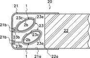
본 발명에 의한 면광원장치(20)는, 방전관(1)으로부터 떨어져서 배치된 리플렉터(21)와, 방전관(1)에 대향해서 배치된 끝단면(22a)을 가진 도광판(22)과, 경우에 따라서 방전관(1)을 규제하는 규제수단(23)을 구비하고 있다. 또한, 본 실시형태의 면광원장치(20)에서는, 도광판(22)의 끝단면(22a)에 수직인 평면(C)에 대해서 각 중간부(2b)의 가장 긴 지름을 나란하게 기울어지게 함과 동시에, 벌브(2)의 중심축을 서로 나란하게 또는 도광판(22a)을 포함한 면에 대해서 정사영(正射影)했을 때, 중복 투영부(A)로써 복수의 방전관(1)을 리플렉터(21) 내에 배치하므로, 면광원장치를 박형화(薄型化)할 수 있음과 동시에 면광원장치의 발광 휘도를 향상시키는 것이 가능해진다.The surface light source device 20 according to the present invention includes a light guide plate 22 having a reflector 21 disposed away from the discharge tube 1, an end surface 22a disposed to face the discharge tube 1, and Therefore, the regulating means 23 which regulates the discharge tube 1 is provided. Moreover, in the surface light source device 20 of this embodiment, the longest diameter of each intermediate part 2b is inclined side by side with respect to the plane C perpendicular | vertical to the end surface 22a of the light guide plate 22, and At the same time, when the central axes of the bulbs 2 are orthogonal to one another or to the plane including the light guide plate 22a, the plurality of discharge tubes 1 are arranged in the reflector 21 as the overlapping projection A. FIG. Therefore, the surface light source device can be reduced in thickness and the light emission luminance of the surface light source device can be improved.

[발명의 효과][Effects of the Invention]

본 발명에서는, 벌브(2)의 중간부(2b)의 단면적이 종래의 벌브보다 작기 때문에, 한 쌍의 전극(4) 사이에서 벌브(2)의 중간부(2b)로 흐르는 관전류의 전류 밀도를 종래의 방전관보다 증가시켜, 방전관의 발광 휘도를 향상시킬 수 있다. 또한, 원형 고리형상 단면의 양 끝단부(2a) 내에 종래의 원형 단면의 전극(4)을 배치할 수 있다. 이 경우, 전극(4)을 대형화하여 큰 전류화를 도모해도 전극(4)과 벌브(2)의 내벽과의 간격을 비교적 크게 취할 수 있으므로, 전극(4)의 스퍼터링에 의해 생성되는 수은 아말감의 침착(沈着)에 의한 방전관(1)의 흑화현상을 억제할 수 있고, 고휘도이고 긴 수명의 방전관(1)을 얻을 수 있다. 또한, 벌브(2)의 양 끝단부(2a)와 중간부(2b)의 둘레의 길이를 동일하게 하면, 벌브(2)의 표면적이 종래의 원형 고리형상 단면의 벌브와 같아져, 큰 발광 면적을 얻을 수 있어, 고휘도화가 높은 수준으로 달성된다. 또한, 원형 고리형상 단면을 가진 종래의 벌브를 이용하여 중앙 부분을 편평형으로 하는 정도의 간단한 가공으로 방전관을 비교적 염가로 제조할 수 있다. 또한, 컵형상 또는 원통형상의 전극(4)의 지름을 벌브(2)의 중간부(2b)의 가장 짧은 지름보다 크게 하면, 전극(4)의 안쪽으로부터 벌브(2)의 중간부(2b)로 원활하게 전자가 방출되고, 그 전자가 전극(4)의 중앙측을 지배적으로 흐르기 때문에, 전극(4)의 측면에서의 전자의 방출을 억제할 수 있다. 결과적으로, 전극(4)의 스퍼터링에 의해 생성되는 수은 아말감의 침착에 의한 방전관(1)의 흑화현상을 양호하게 억제하여, 방전관(1)의 장기 수명화를 높은 수준으로 도모할 수 있다. 또한, 컵형상 또는 원통형상의 전극(4)의 지름을 벌브(2)의 중간부(2b)의 가장 짧은 지름보다 크게 하면, 전극(4)으로부터 방출된 전자가 벌브(2)의 중간부(2b)로 양호하게 흐르므로, 고휘도화를 도모할 수 있다. 또한, 접속부(2c)를 테이퍼 형상으로 하면, 전극(4)의 선단부와 벌브(2)의 중간부(2b)와의 거리를 충분히 확보할 수 있어, 흑화현상 방지에 유리하다. 또한, 양 끝단부(2a)로부터 중간부(2b)를 향해서 서서히 지름이 축소 및 지름이 확대되는 지름축소부(2d) 및 지름확대부(2e)를 가진 접속부(2c)를 설치하면, 전극(4)으로부터 방출된 전자가, 보다 벌브(2) 및 전극(4)의 중앙측을 흐르기 쉬워진다. 또한, 벌브(2)의 중간부(2b)의 길이(LB)를, 양 끝단부(2a)의 길이의 총합(LA1+LA2)보다 길게 하면, 발광 영역을 증대시켜 고휘도화를 도모할 수 있다.In the present invention, since the cross-sectional area of the middle portion 2b of the bulb 2 is smaller than that of the conventional bulb, the current density of the tube current flowing between the pair of electrodes 4 to the middle portion 2b of the bulb 2 is determined. By increasing it compared with the conventional discharge tube, the light emission luminance of a discharge tube can be improved. Moreover, the electrode 4 of the conventional circular cross section can be arrange | positioned in the both ends 2a of circular circular cross section. In this case, the distance between the electrode 4 and the inner wall of the bulb 2 can be made relatively large even if the electrode 4 is enlarged to achieve a large current, so that the mercury amalgam produced by the sputtering of the electrode 4 The blackening phenomenon of the discharge tube 1 by deposition can be suppressed, and the discharge tube 1 of high brightness and long lifetime can be obtained. Moreover, when the lengths of the circumferences of the both ends 2a and the intermediate part 2b of the bulb 2 are made the same, the surface area of the bulb 2 will become the same as the bulb of the conventional circular annular cross section, and a large light emitting area Can be obtained, and high luminance is achieved at a high level. In addition, by using a conventional bulb having a circular annular cross section, the discharge tube can be produced relatively inexpensively by a simple process such that the center portion is flat. Moreover, when the diameter of the cup-shaped or cylindrical electrode 4 is made larger than the shortest diameter of the middle part 2b of the bulb 2, it will go from the inside of the electrode 4 to the middle part 2b of the bulb 2. Since electrons are smoothly emitted and the electrons predominantly flow through the center side of the electrode 4, the emission of electrons on the side surface of the electrode 4 can be suppressed. As a result, the blackening phenomenon of the discharge tube 1 by the deposition of the mercury amalgam produced by sputtering of the electrode 4 can be suppressed favorably, and long life of the discharge tube 1 can be extended to a high level. In addition, when the diameter of the cup-shaped or cylindrical electrode 4 is made larger than the shortest diameter of the middle portion 2b of the bulb 2, the electrons emitted from the electrode 4 become the middle portion 2b of the bulb 2. Since it flows satisfactorily), high brightness can be attained. In addition, when the connecting portion 2c is tapered, the distance between the tip of the electrode 4 and the middle portion 2b of the bulb 2 can be sufficiently secured, which is advantageous for preventing blackening. Further, when the connecting portion 2c having the diameter reducing portion 2d and the diameter expanding portion 2e, which are gradually reduced in diameter and enlarged in diameter from both ends 2a to the middle portion 2b, is provided, the electrode ( The electrons emitted from 4) more easily flow through the center side of the bulb 2 and the electrode 4. Further, when the length L B of the middle portion 2b of the bulb 2 is longer than the sum L A1 + L A2 of the lengths of the both ends 2a, the light emitting area is increased to achieve high luminance. can do.

또한, 본 발명의 방전관의 벌브(2)의 가장 긴 지름의 일끝단을 도광판(22)의 끝단면(22a)에 대향시켜 배치하거나, 또는 도광판(22)의 끝단면(22a)에 수직인 평면에 대해서 복수의 방전관의 벌브(2)의 가장 긴 지름을 나란하게 기울이고 또한 관중심축을 서로 나란하게 하여 각 방전관을 리플렉터 내에 배치하는 본 발명의 면광원장치에서는, 종래보다 박형이고 고휘도의 면광원장치를 실현할 수 있다. 또한, 각 방전관(1)의 벌브(2)의 중간부(2b)는, 도광판(22)의 끝단면(22a)을 포함한 면에 대해서 정사영했을 때, 중복 투영부(A)를 형성하므로, 박형이고 고휘도의 면광원장치를 실현할 수 있다. 또한, 방전관(1)의 벌브(2)의 중간부(2b)를 지지하고 또한 중간부(2b)의 경사각도(θ)를 규제하는 규제수단(23)을 벌브(2)의 중간부(2b)에 장착하므로, 벌브(2)를 지정한 위치에 고정하고, 진동에 의한 벌브(2)의 파괴를 더 저감 할 수 있다.Further, one end of the longest diameter of the bulb 2 of the discharge tube of the present invention is disposed opposite the end surface 22a of the light guide plate 22, or is a plane perpendicular to the end surface 22a of the light guide plate 22. In the surface light source device of the present invention in which the longest diameters of the bulbs 2 of the plurality of discharge tubes are inclined side by side and the center of gravity of the discharge tubes are arranged side by side with each other, the respective discharge tubes are arranged in the reflector. Can be realized. In addition, since the intermediate part 2b of the bulb 2 of each discharge tube 1 forms the overlapping projection part A when orthogonally projecting to the surface containing the end surface 22a of the light guide plate 22, it is thin And a high brightness surface light source device can be realized. Moreover, the control means 23 which supports the intermediate part 2b of the bulb 2 of the discharge tube 1, and regulates the inclination angle (theta) of the intermediate part 2b is provided with the intermediate part 2b of the bulb 2 ), The bulb 2 can be fixed at a designated position, and the breakage of the bulb 2 due to vibration can be further reduced.

도 1은 본 발명에 의한 방전관의 실시형태를 나타내는 사시도 1 is a perspective view showing an embodiment of a discharge tube according to the present invention.

도 2는 도 1의 실제 장착할 때의 평단면도Figure 2 is a plan sectional view of the actual mounting of Figure 1

도 3은 도 1의 실제 장착할 때의 측단면도Figure 3 is a side cross-sectional view of the actual mounting of Figure 1

도 4는 도 1의 실제 장착할 때의 정면도 4 is a front view of the actual mounting of FIG.

도 5는 도 2의 일부 확대 단면도5 is a partially enlarged cross-sectional view of FIG.

도 6은 벌브를 성형틀 내에 배치하는 상태를 나타내는 측단면도Fig. 6 is a side cross-sectional view showing a state where the bulb is disposed in the mold.

도 7은 도 6의 평단면도7 is a cross-sectional view of FIG. 6

도 8은 도 6의 성형틀을 틀체결하는 상태를 나타내는 측단면도Figure 8 is a side cross-sectional view showing a state of fastening the mold of Figure 6

도 9는 도 6에 나타내는 공정으로 얻어진 벌브의 내벽부에 형광막을 피착하는 상태를 나타내는 측단면도9 is a side cross-sectional view showing a state in which a fluorescent film is deposited on an inner wall portion of a bulb obtained by the process shown in FIG. 6.

도 10은 본 발명에 의한 방전관을 사용하는 면광원장치의 다른 실시형태를 나타내는 단면도10 is a cross-sectional view showing another embodiment of the surface light source device using the discharge tube according to the present invention.

도 11는 규제부재 및 파지편을 상세하게 나타내는 정단면도11 is a front sectional view showing in detail the restriction member and the gripping piece;

도 12는 도 11의 사시단면도12 is a perspective cross-sectional view of FIG.

[부호의 설명][Description of the code]

(1) ‥ 방전관 (2) ‥ 벌브 (1) ‥ discharge tube (2) ‥ bulb

(2a) ‥ 양 끝단부 (2b) ‥ 중간부 (2a) ‥ both ends (2b) ‥ middle part

(2c) ‥ 접속부 (2d) ‥ 지름축소부(2c) ‥ connection part (2d) ‥ diameter reduction part

(2e) ‥ 지름확대부 (3) ‥ 폐쇄공간 (2e) ‥ diameter expansion part (3) ‥ closed space

(4) ‥ 전극 (5) ‥ 형광막 (4) ‥ electrode (5) ‥ fluorescent film

(6) ‥ 도출부 (7) ‥ 매설부(6) ‥ derivation part (7) ‥ buried part

(8) ‥ 팽창부 (9) ‥ 단자 부재 (8) ‥ expansion part (9) ‥ terminal member

(10) ‥ 외부 단자 (11) ‥ 컵부 (10) ‥ external terminal (11) ‥ cup

(20) ‥ 면광원장치 (21) ‥ 리플렉터(20) ‥ surface light source device (21) ‥ reflector

(21a) ‥ 반사면 (21b) ‥ 파지편(고정수단) (21a) ‥ reflective surface (21b) ‥ gripping piece (fixing means)

(22) ‥ 도광판 (22a) ‥ 끝단면 (22) ‥ light guide plate (22a) ‥ end surface

(23) ‥ 규제부재(규제수단) (23a) ‥ 지지부(23) ‥ regulating member (regulating means) (23a) ‥ support

(23b) ‥ 연장부 (23c) ‥ 절개부 (23b) ‥ extension (23c) ‥ incision

(30) ‥ 성형틀 (31) ‥ 상형 (30) ‥ mold (31) ‥ upper mold

(32) ‥ 하형 (31a,32a) ‥ 반원주형 오목면(32) ‥ lower die (31a, 32a) ‥ semi-circular concave

(31b,32b) ‥ 반타원주형 오목면 (31c,32c) ‥ 테이퍼형 오목면(31b, 32b) ‥ Semi-elliptical concave surface (31c, 32c) ‥ Tapered concave surface

(33,34) ‥ 고정틀틀 (33a) ‥ 가스 공급 구멍 (33,34) ‥ Fixed frame (33a) ‥ Gas supply hole

(34a) ‥ 평탄면(34a) ‥ flat surface

이하에, 본 발명에 의한 방전관의 실시의 형태를 도 1∼도 9에 대하여 설명한다. 또한, 본 발명에 의한 방전관을 사용하는 면광원장치의 실시의 형태를 도 10 및 도 11에 대하여 설명한다.EMBODIMENT OF THE INVENTION Below, embodiment of the discharge tube which concerns on this invention is described about FIGS. 10 and 11 illustrate embodiments of the surface light source device using the discharge tube according to the present invention.

본 실시형태의 방전관(1)은, 도 1∼도 4에 나타낸 바와 같이, 방전용 가스를 수용하는 폐쇄 공간(3)을 형성하는 유리제의 벌브(2)와, 벌브(2)의 양끝단에 기밀로 융착되고 또한 폐쇄 공간(3) 내에 배치된 한 쌍의 전극(4)과, 벌브(2)의 내벽면에 피착된 형광막(5)을 구비한다. 벌브(2)는, 전극(4)이 설치되고 또한 원형 고리형상 단면을 가진 양 끝단부(2a)와 타원형 고리형상 단면으로 양 끝단부(2a) 사이에 형성되고 또한 지름 방향의 단면적이 양 끝단부(2a)보다 작은 중간부(2b)와, 양 끝단부(2a)와 중간부(2b)를 접속하는 접속부(2c)를 구비한다. 벌브(2)의 중간부(2b)의 둘레의 길이는 실질적으로 양 끝단부(2a)의 둘레의 길이와 동일하다. 접속부(2c)는, 양 끝단부(2a)로부터 중간부(2b)를 향해서 서서히 지름이 축소하는 지름축소부(2d)와, 지름축소부(2d)로부터 둘레방향으로 떨어지고 또한 지름축소부(2d)에 접속되어 양 끝단부(2a)로부터 중간부(2b)를 향해서 서서히 지름이 확대되는 지름확대부(2e)를 가진다. 또한, 벌브(2)의 중간부(2b)의 길이(LB)는 양 끝단부(2a)의 길이의 총합(LA1+LA2)보다 길다.As shown in FIGS. 1-4, the discharge tube 1 of this embodiment is formed in the glass bulb 2 which forms the closed space 3 which accommodates gas for discharge, and the both ends of the bulb 2, respectively. A pair of electrodes 4 fused in airtight and disposed in the closed space 3 and a fluorescent film 5 deposited on the inner wall surface of the bulb 2 are provided. The bulb 2 is provided between the both ends 2a with the electrode 4 and having a circular annular cross section and an elliptical annular cross section between the two end portions 2a and a radial cross section having both ends. The intermediate part 2b smaller than the part 2a, and the connection part 2c which connects the both ends 2a and the intermediate part 2b are provided. The length of the circumference of the middle part 2b of the bulb 2 is substantially the same as the length of the circumference of the both ends 2a. The connecting portion 2c is a diameter reducing portion 2d which gradually decreases in diameter from both end portions 2a toward the intermediate portion 2b, and is separated from the diameter reducing portion 2d in the circumferential direction and further reduced in diameter 2d. It has a diameter enlargement part 2e which is connected to the () and gradually enlarges a diameter toward the middle part 2b from both end parts 2a. In addition, the length L B of the middle portion 2b of the bulb 2 is longer than the sum L A1 + L A2 of the lengths of the both ends 2a.

벌브(2)의 폐쇄 공간(3) 내에는, 방전용 가스로서 예를 들면 종래의 아르곤 가스 등의 희가스와 수은증기 등의 가스가 충전된다. 전극(4)은, 예를 들면 니켈에 의해 형성되는 도출부(6)와, 예를 들면 텅스텐에 의해 형성되는 매설부(7)와, 원통의 일끝단을 폐색한 컵형상으로 형성되는 컵부(11)를 구비하고 있다. 또, 컵부(11) 대신에 원통형상(슬리브 형상)의 전극을 설치해도 좋다. 도 5에 나타낸 바와 같이, 컵부(11)의 안지름(W1)은 벌브(2)의 중간부(2b)의 가장 짧은 지름(W2) 보다 크다. 도출부(6)는, 저항용접 등에 의해서 매설부(7)의 일끝단에 융착되고, 그 융착 부분에는 팽창부(8)가 형성된다. 도출부(6) 및 매설부(7)는 단자부재(9)를 구성한다. 도 2∼도 4에 나타낸 바와 같이, 도출부(6)는 벌브(2)의 양 끝단부(2)로부터 외부로 도출되고, 땜납을 통하여 외부 단자(10)에 접속된다. 따라서, 도출부(6)는 니켈 등의 납땜성이 양호한 금속에 의해서 형성하는 것이 바람직하다. 매설부(7)에는 벌브(2)의 양 끝단부(2a)가 융착되고, 그 한쪽의 끝단부 측이 벌브(2)의 내부에 도입된다. 따라서, 매설부(7)는 벌브(2)를 구성하는 재료와 양호하게 밀착하는 금속에 의해서 형성하는 것이 바람직하다. 예를 들면, 자외선 차단 효과를 가진 유리재와 양호하게 밀착하는 텅스텐은, 매설부(7)를 형성하는 재료로서 바람직하다. 컵부(11)는, 타발(blanking)가공 또는 스피닝(spinning) 가공 등에 의해 컵형상으로 형성되고, 저항용접 등에 의해서 매설부(7)의 다른 끝단에 융착된다. 형광막(5)은, 한 쌍의 전극(4) 사이의 방전에 의해 발생하는 자외선의 조사를 받아 가시광선을 방출한다.The closed space 3 of the bulb 2 is filled with a rare gas such as a conventional argon gas and a gas such as mercury vapor as a discharge gas. The electrode 4 includes, for example, a lead portion 6 formed of nickel, a buried portion 7 formed of, for example, tungsten, and a cup portion formed in a cup shape in which one end of the cylinder is blocked. 11). In addition, a cylindrical (sleeve) electrode may be provided instead of the cup portion 11. As shown in FIG. 5, the inner diameter W 1 of the cup portion 11 is larger than the shortest diameter W 2 of the middle portion 2b of the bulb 2. The lead portion 6 is fused to one end of the buried portion 7 by resistance welding or the like, and an expanded portion 8 is formed at the welded portion thereof. The lead portion 6 and the buried portion 7 constitute a terminal member 9. As shown in FIGS. 2-4, the lead-out part 6 is led out from the both ends 2 of the bulb 2, and is connected to the external terminal 10 via solder. Therefore, the lead portion 6 is preferably formed of a metal having good solderability such as nickel. Both end portions 2a of the bulb 2 are fused to the embedding portion 7, and one end side thereof is introduced into the bulb 2. Therefore, it is preferable to form the embedding portion 7 by a metal in good contact with the material constituting the bulb 2. For example, tungsten in good contact with the glass material having the ultraviolet ray blocking effect is preferable as a material for forming the buried portion 7. The cup part 11 is formed in cup shape by a blanking process, a spinning process, etc., and is fused to the other end of the embedding part 7 by resistance welding etc. The fluorescent film 5 is irradiated with ultraviolet rays generated by the discharge between the pair of electrodes 4 to emit visible light.

본 실시형태의 방전관(1)에 의하면, 아래와 같은 효과를 얻을 수 있다.According to the discharge tube 1 of this embodiment, the following effects can be acquired.

[1] 비원형 고리형상 단면의 중간부(2b)는, 원형 고리형상 단면의 양 끝단부(2a)보다 단면적이 작기 때문에, 발광 영역으로서 기능하는 중간부(2b)를 흐르는 관전류의 전류 밀도가 종래의 벌브보다 증가하여, 방전관(1)의 발광 휘도를 향상시킬 수 있다.[1] Since the middle portion 2b of the non-circular annular cross section has a smaller cross-sectional area than both end portions 2a of the circular annular cross section, the current density of the tube current flowing through the intermediate portion 2b serving as a light emitting region is increased. Increased compared with the conventional bulb, the light emission luminance of the discharge tube 1 can be improved.

[2] 원형 고리형상 단면에 형성되는 벌브(2)의 양 끝단부(2a) 내에 종래의 일반적인 원형 단면의 전극(4)을 배치할 수 있다. 또한, 벌브(2)의 중간부(2b)의 둘레의 길이가 실질적으로 양 끝단부(2a)의 둘레의 길이와 동일하므로, 예를 들면 원형 고리형상 단면의 벌브(2)의 중간부(2b)를 가열하여 가압 변형시키는 정도의 간단한 가공으로 도 1에 나타내는 형상의 벌브(2)를 용이하게 형성할 수 있어, 고휘도의 방전관을 염가로 제공할 수 있다. [2] An electrode 4 having a conventional general circular cross section can be arranged in both ends 2a of the bulb 2 formed in the circular annular cross section. In addition, since the length of the periphery of the middle part 2b of the bulb 2 is substantially the same as the length of the periphery of the both ends 2a, the middle part 2b of the bulb 2 of circular circular cross section, for example. ), The bulb 2 of the shape shown in FIG. 1 can be easily formed by the simple process of heating and depressurizing, and a high-brightness discharge tube can be provided in low cost.

[3] 원형 고리형상 단면의 양 끝단부(2a)에 원형 단면의 전극(4)을 설치하기 때문에, 전극(4)을 대형화하여도 전극(4)의 전체둘레에 걸쳐서 컵부(11)와 벌브(2)의 내벽면과의 거리를 충분히 확보할 수 있어, 전극(4)의 스퍼터링에 의해 생성되는 수은 아말감의 침착에 의한 방전관(1)의 흑화현상이 억제된다. 이 때문에, 방전관(1)의 고휘도화와 장수명화를 도모할 수 있다. 특히, 접속부(2c)가 테이퍼 형상으로 형성되기 때문에, 전극(4)의 컵부(11)와 벌브(2)의 중간부(2b)와의 거리를 충분히 확보할 수 있어, 흑화현상 억제 효과를 보다 양호하게 달성할 수 있다. [3] Since the electrodes 4 having a circular cross section are provided at both end portions 2a of the circular annular cross section, the cup portion 11 and the bulb are spread over the entire circumference of the electrode 4 even when the electrode 4 is enlarged. The distance from the inner wall surface of (2) can be fully ensured, and the blackening phenomenon of the discharge tube 1 by the deposition of the mercury amalgam produced | generated by the sputtering of the electrode 4 is suppressed. For this reason, the high brightness and long life of the discharge tube 1 can be aimed at. In particular, since the connection portion 2c is formed in a tapered shape, the distance between the cup portion 11 of the electrode 4 and the intermediate portion 2b of the bulb 2 can be sufficiently secured, and the blackening phenomenon suppressing effect is better. Can be achieved.

[4] 전극(4)의 컵부(11)의 지름(W1)이 벌브(2)의 중간부(2b)의 가장 짧은 지름(W2)보다 크기 때문에, 전자가 벌브(2) 및 컵부(11)의 중앙 부근을 흐른다. 이 때문에, 컵부(11)의 측면으로부터의 전자의 방출을 억제할 수 있어, 흑화현상 억제 효과를 보다 높은 수준으로 얻을 수 있음과 동시에, 고휘도화가 양호하게 달성된다.[4] Since the diameter W 1 of the cup portion 11 of the electrode 4 is larger than the shortest diameter W 2 of the middle portion 2b of the bulb 2, the electrons are formed from the bulb 2 and the cup portion ( 11) flow near the center. For this reason, the emission of the electrons from the side surface of the cup part 11 can be suppressed, a blackening phenomenon suppression effect can be obtained at a higher level, and high luminance is achieved satisfactorily.

이어서, 도 1에 나타내는 방전관(1)의 제조 방법에 대하여 설명한다. 먼저, 원형 고리형상 단면을 가진 벌브(2)를 준비한다. 다음에, 도 6 및 도 7에 나타낸 바와 같이, 원형 고리형상 단면을 가진 벌브(2)를 성형틀(30) 내에 배치한다. 성형틀(30)은, 도 6에 나타낸 바와 같이 상형(31), 하형(32) 및 한 쌍의 고정틀(33, 34)로 구성되고, 상형(31) 및 하형(32)은 벌브(2)의 양 끝단면에 맞닿는 각 고정틀(33, 34) 사이에 서로 접근 및 떨어질 수 있게 배치된다. 상형(31) 및 하형(32)의 접촉면에는, 각각 벌브(2)의 양 끝단부(2a)를 원형 고리형상 단면으로 형성하는 반원주형 오목면(31a, 32a)과, 벌브(2)의 중간부(2b)를 타원형 고리형상 단면으로 형성하는 반타원주형 오목면(31b, 32b)과, 반원주형 오목면(31a, 32a)과 반타원주형 오목면(31b, 32b)의 사이에 개재하고 또한 벌브(2)의 접속부(2c)를 형성하는 테이퍼형 오목면(31c,32c)이 형성된다. 따라서, 상형(31)과 하형(32)을 닫았을 때, 성형틀(30) 내에는 형성해야 할 벌브(2)의 형상에 합치하는 캐비티(cavity)(빈 부분)가 형성된다. 또한, 한쪽의 고정틀(33)에는 벌브(2)의 일끝단으로부터 벌브 내에 가스를 공급하는 가스 공급 구멍(33a)이 형성되고, 다른쪽의 고정틀(34)에는 벌브(2)의 다른 끝단을 폐색하는 평탄면(34a)이 형성된다. 상형(31) 및 하형(32)에는 벌브(2)를 가열하는 도시하지 않은 히터가 내장된다.Next, the manufacturing method of the discharge tube 1 shown in FIG. 1 is demonstrated. First, a bulb 2 having a circular annular cross section is prepared. Next, as shown in FIG. 6 and FIG. 7, the bulb 2 having a circular annular cross section is disposed in the mold 30. As shown in FIG. 6, the shaping | molding die 30 is comprised from the upper mold | type 31, the lower mold | type 32, and a pair of fixing frames 33 and 34, and the upper mold | type 31 and the lower mold | type 32 are bulbs 2 Between each fixing frame (33, 34) in contact with both end faces of the is arranged to be approached and separated from each other. On the contact surface of the upper mold | type 31 and the lower mold | type 32, the semicircular recessed surfaces 31a and 32a which form the both ends 2a of the bulb 2 in circular annular cross section, respectively, and the middle of the bulb 2 are It interposes between the semi-elliptic concave surfaces 31b and 32b which form the part 2b in an elliptical annular cross section, and between the semi-circular concave surfaces 31a and 32a and the semi-elliptic concave surfaces 31b and 32b, and Tapered concave surfaces 31c and 32c forming the connection portion 2c of the bulb 2 are formed. Therefore, when the upper mold 31 and the lower mold 32 are closed, a cavity (empty portion) is formed in the mold 30 to match the shape of the bulb 2 to be formed. In addition, one fixing frame 33 is provided with a gas supply hole 33a for supplying gas into the bulb from one end of the bulb 2, and the other fixing frame 34 closes the other end of the bulb 2. A flat surface 34a is formed. The upper mold | type 31 and the lower mold | type 32 contain the heater which is not shown in figure which heats the bulb 2.

도 6 및 도 7에 나타낸 바와 같이, 성형틀(30) 내에 벌브(2)를 배치한 후, 상형(31) 및 하형(32)에 내장된 도시하지 않은 히터에 의해 벌브(2)를 가열함과 동시에, 한쪽의 고정틀(33)의 가스 공급 구멍(33a)으로부터 벌브(2) 내로 가압된 공기 또는 불활성 가스 등의 취입가스를 공급하여, 외력이 가해지는 벌브(2)의 눌려 찌부러짐을 방지한다. 그 후, 도 8에 나타낸 바와 같이, 상형(31) 및 하형(32)을 서로 접근시켜 상형(31)과 하형(32)을 닫고, 성형틀(30)을 틀 체결함과 동시에, 벌브(2) 내에 가압된 취입가스를 더 공급한다. 이에 따라, 벌브(2)의 양 끝단부(2a)가 원형 고리형상 단면에 유지됨과 동시에, 벌브(2)의 중간부(2b)의 상부와 하부가 취입가스에 의해 팽창하여, 지름이 확대됨과 동시에, 중간부(2b)의 좌우측부가 상형(31)과 하형(32)에 의해 눌려져 지름이 축소하고, 중간부(2b)는, 타원형 고리형상 단면으로 형성된다. 이와 동시에, 벌브(2)의 접속부(2c)가 양 끝단부(2)로부터 중간부(2b)를 향해서 서서히 지름이 축소되는 지름축소부(2d)와 지름축소부(2d)에 접속되어 양 끝단부(2a)로부터 중간부(2b)를 향해서 서서히 지름이 확대되는 지름확대부(2e)를 가진 경사면 형상 또는 만곡 형상으로 형성된다. 벌브(2)의 냉각 경화 후, 상형(31) 및 하형(32)을 서로 떨어지게 하여 상형(31)과 하형(32)을 개방하고, 성형틀(30)으로부터 벌브(2)를 꺼내면, 도 1에 나타낸 외형의 벌브(2)를 얻을 수 있다. 이와 같이, 상형(31)과 하형(32)에 의해 벌브(2)의 중간부(2b)를 지름 축소 방향으로 누름과 동시에, 상형(31)과 하형(32)의 누름 방향과는 직각인 지름 확대 방향으로 중간부(2b)를 가압가스에 의해 팽창시키면서 가압가스의 취입성형을 실시하는 것이 바람직하다. 물론, 수직 방향으로 틀 체결과 틀 개방을 실시하는 상형(31)과 하형(32) 대신에, 수평 방향의 좌우로 이동하여 틀 체결과 틀 개방을 실시하는 제 1 틀과 제 2 틀부터 완성되는 한 쌍의 틀(型)을 사용해도 좋다.6 and 7, after placing the bulb 2 in the mold 30, the bulb 2 is heated by a heater (not shown) built into the upper mold 31 and the lower mold 32. At the same time, blowing gas, such as pressurized air or inert gas, is supplied from the gas supply hole 33a of one fixing frame 33 into the bulb 2, thereby preventing crushing of the bulb 2 to which external force is applied. . Then, as shown in FIG. 8, the upper mold | type 31 and the lower mold | type 32 approach each other, the upper mold | type 31 and the lower mold | type 32 are closed, and the mold 2 is frame-fastened and the bulb 2 ) Further pressurized blowing gas. Accordingly, both ends 2a of the bulb 2 are maintained in a circular annular cross section, and the upper and lower portions of the middle portion 2b of the bulb 2 are expanded by the blowing gas, and the diameter thereof is expanded. At the same time, the left and right sides of the middle portion 2b are pressed by the upper mold 31 and the lower mold 32 to reduce the diameter, and the intermediate portion 2b is formed in an elliptical annular cross section. At the same time, the connection part 2c of the bulb 2 is connected to the diameter reduction part 2d and the diameter reduction part 2d which diameter is gradually reduced toward the middle part 2b from the both ends 2, and both ends, It is formed in an inclined surface shape or a curved shape with a diameter-expansion portion 2e gradually expanding in diameter from the portion 2a toward the middle portion 2b. After cooling and hardening the bulb 2, the upper mold 31 and the lower mold 32 are separated from each other, the upper mold 31 and the lower mold 32 are opened, and the bulb 2 is taken out from the mold 30. FIG. 1 The bulb 2 of the external shape shown in FIG. Can be obtained. As described above, the upper mold 31 and the lower mold 32 press the middle portion 2b of the bulb 2 in the diameter reduction direction, and at the same time, the diameter perpendicular to the pressing direction of the upper mold 31 and the lower mold 32. Blow molding of the pressurized gas is preferably performed while expanding the intermediate portion 2b with the pressurized gas in the enlarged direction. Of course, instead of the upper mold 31 and the lower mold 32 which perform the mold clamping and the mold opening in the vertical direction, the first mold and the second mold which are moved left and right in the horizontal direction to perform the mold clamping and the mold opening are completed. You may use a pair of patterns.

도 1에 나타내는 외형으로 성형된 벌브(2)를 성형틀(30)로부터 꺼낸 후, 벌브(2)의 벽면에 형광 물질을 포함한 액체를 흘려 넣어, 도 9에 나타낸 바와 같이 벌브(2)의 내벽면에 형광막(5)을 피착시킨다. 벌브(2)를 취입 성형한 후에 형광막(5)을 형성하는 대신에, 형광막(5)을 벌브(2)의 벽면에 형성한 후에, 벌브(2)의 취입 성형을 실시해도 좋다. 다음에, 벽면에 형광막(5)이 피착된 벌브(2)를 도시하지 않은 밀폐 가능한 챔버(용기) 내에 삽입하고, 벌브(2)의 양 끝단부(2a)에 한 쌍의 전극(4)의 매설부(7) 및 컵부(11)를 대향시켜 같은 축상에 배치한다. 그 후, 챔버를 밀폐하여 예를 들면 아르곤 가스 등의 희가스와 수은 증기를 포함한 방전용 가스를 벌브(2) 내에 충전하고, 챔버 내에 설치된 전기로 등으로 벌브(2)의 양 끝단을 한 쌍의 전극(4)의 매설부(7)에 융착시킴으로써 벌브(2)의 양 끝단을 폐색하고, 한 쌍의 전극(4)의 컵부(11)를 벌브(2) 내에 밀봉한다.After taking out the bulb 2 shape | molded to the external shape shown in FIG. 1 from the shaping | molding die 30, the liquid containing fluorescent substance was poured in the wall surface of the bulb 2, and the inside of the bulb 2 as shown in FIG. The fluorescent film 5 is deposited on the wall surface. Instead of forming the fluorescent film 5 after the blow molding of the bulb 2, the blow molding of the bulb 2 may be performed after the fluorescent film 5 is formed on the wall surface of the bulb 2. Next, the bulb 2 in which the fluorescent film 5 is deposited on the wall is inserted into a sealable chamber (container) (not shown), and the pair of electrodes 4 are provided at both ends 2a of the bulb 2. The buried portions 7 and the cup portions 11 are arranged to face each other on the same axis. Thereafter, the chamber is sealed to fill the bulb 2 with a rare gas such as argon gas and a discharge gas containing mercury vapor, and a pair of ends of the bulb 2 are connected to each other by an electric furnace installed in the chamber. By fusion bonding to the embedding portion 7 of the electrode 4, both ends of the bulb 2 are closed, and the cup portions 11 of the pair of electrodes 4 are sealed in the bulb 2.

본 실시형태의 방전관(1)의 제조방법에서는, 성형틀(30)을 틀 체결하여 벌브(2)의 중간부(2b)를 타원형 고리형상 단면으로 형성할 때에, 벌브(2) 내에 가스(공기)를 공급하여 가압하므로, 벌브(2)가 형태가 무너지지 않고, 성형틀(30)의 캐비티의 형상에 부합하는 형상으로 중간부(2b)가 형성되고, 균일한 두께로 또한 타원형 고리형상 단면에 벌브(2)의 중간부(2b)를 형성할 수 있다.In the manufacturing method of the discharge tube 1 of this embodiment, when forming the intermediate | middle part 2b of the bulb 2 in an elliptical annular cross section by fastening the shaping | molding die 30, the gas (air) in the bulb 2 is carried out. ), The bulb 2 is not collapsed, and the middle portion 2b is formed in a shape that matches the shape of the cavity of the forming mold 30, and has a uniform thickness and an elliptical annular cross section. The intermediate part 2b of the bulb 2 can be formed.

예를 들면 도 10에 나타내는 에지 조명틀의 면광원장치(20)에 도 1∼도 9에 나타내는 방전관(1)을 적용할 수 있다. 본 실시형태의 면광원장치(20)는, 도 10에 나타낸 바와 같이, 도 1에 나타내는 형상을 가지며 또한 벌브 축방향의 중심선이 서로 나란하게 배치된 2개의 방전관(1)과, 2개의 방전관(1)에 나란하게 또한 각 방전관(1)이 내부에 형성된 반사면(21a)으로부터 떨어져서 배치된 리플렉터(21)와, 2개의 방전관(1)에 대향해서 배치된 끝단면(22a)을 가진 도광판(22)을 구비하고 있다. 각 방전관(1)의 벌브(2)의 중간부(2b)의 가장 긴 지름은, 도광판(22)의 끝단면(22a)에 수직인 평면(C)에 대해서 나란하게, 예를 들면 동일한 각도 θ(0°≤θ≤90°)로 경사져 있다. 다만, 각도 θ가 너무 크면, 종래의 방전관을 사용한 면광원장치보다 외형 치수가 두꺼워지므로, 벌브(2)의 형상에 따라 경사각도 θ가 제 한된다. 2개의 방전관(1)에 있어서, 각 벌브(2)의 중간부(2b)는, 도광판(22)의 끝단면(22a)에 대해서 정사영했을 때에 중복 투영부 A를 형성하고, 중복 투영부 A와 도광판(22)의 끝단면(22a)에 대한 벌브(2)의 중간부(2b)의 경사 투영부 B와의 비 A/B를 0≤(A/B)≤0.5의 범위로 하여 벌브(2)를 배치하는 것이 바람직하다. 또한, 2개의 방전관(1)의 관중심축 O1,O2을 통과하는 평면 D는, 도시한 바와 같이 도광판(22)의 끝단면(22a)에 대해서 반드시 평행이 아니어도 좋다. 또한, 도 11 및 도 12에 나타낸 바와 같이, 2개의 방전관(1)에 있어서, 중간부(2b)를 지지하고 또한 중간부(2b)의 가장 긴 지름의 설치 경사각도 θ를 유지하는 홀더(규제수단)로서의 규제부재(23)를 각각 벌브(2)의 중간부(2b)에 장착한다. 한편, 리플렉터(21)의 반사면(21a)에는, 2개의 방전관(1)의 중간부(2b)에 각각 장착된 규제 부재(23)를 고정하는 고정수단으로서의 한 쌍의 파지편(21b)이 2조 형성된다. 규제부재(23)는, 절개부(23c)를 가져 방전관(1)의 중간부(2b)를 반 이상 포위하는 고리형상의 지지부(23a)와, 지지부(12a)로부터 방전관(1)의 지름 방향 바깥측으로 연장하여 리플렉터(21)의 한 쌍의 파지편(21b)에 끼워 지지되는 연장부(23b)를 구비하여, 예를 들면 아크릴수지 등의 투명도가 높은 수지로 일체로 형성할 수도 있다. 또한, 규제부재(23)는, 벌브(2)가 진동에 의해 파괴하는 것을 억제하는 효과도 가진다. 또, 도 10에서는 2개의 방전관(1)과 리플렉터(21)의 배치 관계를 명확하게 나타내기 위해, 규제부재(23) 및 파지편(21b)의 도시를 생략한다.For example, the discharge tube 1 shown in FIGS. 1-9 can be applied to the surface light source device 20 of the edge illumination frame shown in FIG. As shown in FIG. 10, the surface light source device 20 of this embodiment has the shape shown in FIG. 1, and the two discharge tubes 1 and two discharge tubes 1 in which the center line of the bulb axial direction were arrange | positioned next to each other ( The light guide plate which has the reflector 21 arrange | positioned in parallel with 1), and each discharge tube 1 is arrange | positioned apart from the reflecting surface 21a formed inside, and the end surface 22a arrange | positioned facing two discharge tubes 1 ( 22). The longest diameter of the middle part 2b of the bulb 2 of each discharge tube 1 is parallel with respect to the plane C perpendicular | vertical to the end surface 22a of the light guide plate 22, for example, the same angle (theta). It is inclined at (0 ° ≦ θ ≦ 90 °). However, if the angle θ is too large, the outer dimension becomes thicker than that of a conventional surface light source device using a discharge tube, and the inclination angle θ is limited depending on the shape of the bulb 2. In the two discharge tubes 1, the intermediate portion 2b of each bulb 2 forms a redundant projection portion A when orthogonally projected to the end surface 22a of the light guide plate 22, and the overlapping projection portion A The bulb 2 has a ratio A / B of the oblique projection portion B of the middle portion 2b of the bulb 2 with respect to the end surface 22a of the light guide plate 22 in a range of 0 ≦ (A / B) ≦ 0.5. It is preferable to arrange. In addition, or may be not parallel to the end surface (22a) of the two discharge tube 1 spectators mandrel O 1, O 2 is D plane, the light guide plate 22 as shown to pass a. In addition, as shown in FIG. 11 and FIG. 12, in the two discharge tubes 1, the holder which supports the intermediate | middle part 2b and maintains the installation inclination angle (theta) of the longest diameter of the intermediate part 2b (regulation | regulation) The regulating member 23 as a means) is attached to the intermediate portion 2b of the bulb 2, respectively. On the other hand, on the reflecting surface 21a of the reflector 21, a pair of holding pieces 21b as fixing means for fixing the restricting members 23 mounted on the middle portions 2b of the two discharge tubes 1, respectively, are provided. Two sets are formed. The restricting member 23 has an annular support 23a that has a cutout 23c and surrounds the middle portion 2b of the discharge tube 1 by half or more, and the radial direction of the discharge tube 1 from the support 12a. An extension portion 23b extending outward and fitted to the pair of gripping pieces 21b of the reflector 21 may be integrally formed of a resin having high transparency such as acrylic resin. In addition, the restricting member 23 also has an effect of suppressing the bulb 2 from being destroyed by vibration. In addition, in FIG. 10, illustration of the restriction member 23 and the holding | gripping piece 21b is abbreviate | omitted in order to show the arrangement relationship of the two discharge tubes 1 and the reflector 21 clearly.

본 실시형태의 면광원장치(20)에 의하면, 아래와 같은 효과를 얻을 수 있다.According to the surface light source device 20 of this embodiment, the following effects can be acquired.

[1] 방전관(1)으로부터 직접 도광판(22)의 끝단면(22a)과 대향하는 리플렉터(21)의 반사면(21a)에서 반사하는 빛의 추출면이 좁아지므로, 리플렉터(21)와 방전관(1)의 사이에서 반사를 반복하는 빛이 저감되어, 방전관(1)으로부터 방출되는 빛을 효과적으로 활용할 수 있다. [1] Since the extraction surface of light reflected from the reflecting surface 21a of the reflector 21 facing the end surface 22a of the light guide plate 22 directly from the discharge tube 1 is narrowed, the reflector 21 and the discharge tube ( The light which repeats reflection between 1) is reduced, and the light emitted from the discharge tube 1 can be utilized effectively.

[2] 도 10에 나타낸 바와 같이, 2개의 방전관(1)의 중간부(2b)가 도광판(22)의 끝단면(22a)에 대해서 중복 투영부 A를 형성하는 경우는, 리플렉터(21) 및 도광판(22)의 두께를 얇게 할 수 있음과 동시에, 2개의 방전관(1)의 중간부(2b)로부터 발생하는 빛이 중첩되어 리플렉터(21)의 반사면(21a)에서 반사되기 때문에, 박형이고 고휘도인 면광원장치(20)를 실현할 수 있다. [2] As shown in FIG. 10, when the intermediate portion 2b of the two discharge tubes 1 forms the overlapped projection portion A with respect to the end surface 22a of the light guide plate 22, the reflector 21 and Since the thickness of the light guide plate 22 can be reduced and light generated from the middle portion 2b of the two discharge tubes 1 overlaps and is reflected by the reflecting surface 21a of the reflector 21, it is thin. The surface light source device 20 of high brightness can be realized.

[3] 2개의 방전관(1)의 중간부(2b)에 각각 규제부재(23)를 장착함과 동시에, 각 규제부재(23)의 연장부(23b)를 리플렉터(21)에 설치된 2조의 파지편(21b)에 끼워 지지시켜 2개의 방전관(1)을 리플렉터(21) 내에 고정하므로, 용이하게 2개의 방전관(1)의 중간부(2b)를 각각 원하는 각도로 경사지게 하여 고정할 수 있다.[3] Two sets of grippers provided with the restricting members 23 in the middle portions 2b of the two discharge tubes 1, and the extension portions 23b of the respective restricting members 23 are provided in the reflector 21. Since the two discharge tubes 1 are fixed in the reflector 21 by being held by the pieces 21b, the middle portions 2b of the two discharge tubes 1 can be easily inclined and fixed at the desired angles, respectively.

본 발명의 실시형태는 상기의 실시형태에 한정되지 않고, 여러 가지로 변경이 가능하다. 예를 들면, 도 1∼도 9에서는 타원형의 고리형상 단면을 가진 중간부(2b)의 벌브(2)를 나타내지만, 벌브(2)의 중간부(2b)의 단면 형상은, 소위 작은 타원형을 포함한 타원형 단면, 반원형을 포함한 D자형 단면의 어느 것이라도 좋다. 또한, 도 10∼도 12에서는 벌브 축방향의 중심선이 서로 나란하게 2개의 방전관(1)을 리플렉터(21) 내에 배치하는 예에 대하여 나타내지만, 방전관(1)의 개수는 2개에 한정되지 않고, 3개 이상이라도 좋다. 또한, 도 11 및 도 12에서는, 절개 부(23c)를 가져 방전관(1)의 중간부(2b)를 반 이상 포위하는 고리형상의 지지부(23a)와, 지지부(12a)로부터 방전관(1)의 지름 방향 바깥측으로 연장하여 리플렉터(21)의 한 쌍의 파지편(21b)에 끼워 지지되는 연장부(23b)를 구비한 규제부재(23)를 나타내지만, 방전관(1)의 중간부(2b)를 삽입하는 개방구멍부 또는 방전관(1)의 중간부(2b)를 반 이상 포위하는 오목부를 가지며 또한 리플렉터(21)와 일체화된 규제부재를 사용해도 좋다. 또한, 2개의 방전관(1)의 관 중심축 O1,O2을 통과하는 평면 D가 도광판(22)의 끝단면(22a)에 대해서 평행이 아닌 예를 나타내지만, 2개의 방전관(1)의 관 중심축 O1,O2을 통과하는 평면 D가 도광판(22)의 끝단면(22a)에 대해서 평행하게 2개의 방전관(1)을 배치해도 좋다. 또한, 면광원장치(20)의 방전관(1)은 1개라도 좋고, 이 경우는 방전관(1)의 벌브(2)의 가장 긴 지름의 일끝단을 도광판(22)의 끝단면(22a)에 대향시켜 배치하면, 도 10에 나타내는 경우와 같이 종래보다 박형으로 고휘도의 면광원장치를 실현할 수 있다. 또한, 본 발명의 방전관(1)은 도한 직관(直管)뿐만 아니라, U자관이나 L자관 등의 만곡부를 가진 형광방전관에도 적용할 수도 있다. 또한, 본 발명은 유리관(2)의 내벽면에 형광막(5)을 형성하지 않는 냉음극형 살균등 등에도 적용할 수 있다.Embodiment of this invention is not limited to said embodiment, A various change is possible. For example, although the bulb 2 of the intermediate part 2b which has an elliptical annular cross section is shown in FIGS. 1-9, the cross-sectional shape of the intermediate part 2b of the bulb 2 is what is called a small oval. Either an elliptical cross section or a D-shaped cross section including a semicircle may be used. In addition, although the center line of the bulb axial direction arrange | positions two discharge tubes 1 in the reflector 21 in FIG. 10-12, the number of discharge tubes 1 is not limited to two, although FIG. 3 or more may be sufficient. In addition, in FIG. 11 and FIG. 12, the annular support part 23a which has cut-out part 23c and surrounds the intermediate part 2b of the discharge tube 1 more than half, and the discharge part of the discharge tube 1 from the support part 12a is shown. Although it shows the restricting member 23 which has the extension part 23b extended radially outward and fitted to the pair of holding pieces 21b of the reflector 21, the middle part 2b of the discharge tube 1 is shown. The restricting member which has a concave portion enclosing half or more of the opening hole part or the intermediate part 2b of the discharge tube 1 which inserts into it may also be used. In addition, the two discharge tube 1 of the tube central axis O 1, O 2 plane D the light guide plate 22, the end surfaces exhibits an example, not for parallel to (22a), two discharge tubes (1) through the The plane D passing through the tube center axes O 1 and O 2 may arrange two discharge tubes 1 in parallel with the end surface 22a of the light guide plate 22. In addition, one discharge tube 1 of the surface light source device 20 may be used, and in this case, one end of the longest diameter of the bulb 2 of the discharge tube 1 is connected to the end surface 22a of the light guide plate 22. If they face each other, as shown in FIG. 10, the surface light source device of higher brightness can be realized thinner than the conventional one. In addition, the discharge tube 1 of the present invention can be applied not only to a straight tube but also to a fluorescent discharge tube having curved portions such as a U-shaped tube and an L-shaped tube. The present invention can also be applied to cold cathode sterilization lamps and the like which do not form the fluorescent film 5 on the inner wall surface of the glass tube 2.

본 발명은, 예를 들면 박형이고 대화면의 액정표시장치에 탑재된 백 라이트 등의 면광원장치로 사용하는 방전관에 양호하게 적용하는 것이 가능하다.The present invention can be favorably applied to, for example, a discharge tube used in a surface light source device such as a backlight mounted on a large-sized liquid crystal display device.

Claims (9)

폐쇄 공간을 형성하는 벌브와, 상기 벌브의 양 끝단에 고정되고 또한 상기 폐쇄 공간 내에 배치된 한 쌍의 전극을 구비하며, 한 쌍의 상기 전극 사이에 전압을 인가하여 발광시키는 냉음극 방전관에 있어서,A cold cathode discharge tube having a bulb forming a closed space, and a pair of electrodes fixed to both ends of the bulb and disposed in the closed space, wherein the cold cathode discharge tube emits light by applying a voltage between the pair of electrodes. 상기 벌브는, 상기 전극이 배치되고 또한 원형 고리형상 단면을 가진 양 끝단부와, 비원형 고리형상 단면으로 상기 양 끝단부 사이에 형성되고 또한 지름 방향의 단면적이 상기 양 끝단부보다 작은 중간부와, 상기 양 끝단부와 상기 중간부를 접속하는 접속부를 구비하고,The bulb includes: an end portion at which the electrode is disposed and having a circular annular cross section; an intermediate portion formed between the both ends with a non-circular annular cross section and having a radial cross section smaller than both ends; And a connecting portion for connecting the both ends and the intermediate portion, 상기 전극은, 상기 벌브의 중간부의 가장 짧은 지름보다 큰 지름의 컵부 또는 통형상부를 가진 것을 특징으로 하는 냉음극 방전관.The electrode has a cold cathode discharge tube, characterized in that it has a cup portion or a cylindrical portion having a diameter larger than the shortest diameter of the middle portion of the bulb. 제1항에 있어서,The method of claim 1, 상기 중간부의 둘레의 길이는 상기 양 끝단부의 둘레의 길이와 동일한 것을 특징으로 하는 냉음극 방전관.The length of the circumference of the intermediate portion is the same as the length of the circumference of the both ends of the cold cathode discharge tube. 제1항에 있어서,The method of claim 1, 상기 접속부는, 상기 양 끝단부로부터 상기 중간부를 향해서 서서히 지름이 축소되는 지름축소부와, 상기 지름축소부로부터 둘레방향으로 떨어지고 또한 상기 지름축소부에 접속되어 상기 양 끝단부로부터 상기 중간부를 향해서 서서히 지름이 확대되는 지름확대부를 가진 것을 특징으로 하는 냉음극 방전관.The connecting portion includes a diameter reducing portion which gradually decreases in diameter from both ends toward the middle portion, and is separated in the circumferential direction from the diameter reducing portion and is connected to the diameter reducing portion to gradually move toward the intermediate portion from both ends. A cold cathode discharge tube, characterized in that the diameter expansion portion having an enlarged diameter. 제 1 항 내지 제 3 항 중의 어느 한 항에 있어서, 상기 벌브의 상기 중간부의 길이는, 상기 양 끝단부의 길이의 총합보다 긴 냉음극 방전관.The cold cathode discharge tube according to any one of claims 1 to 3, wherein a length of the intermediate portion of the bulb is longer than a sum of lengths of the both ends. 제 1 항 내지 제 3 항 중의 어느 한 항에 기재된 냉음극 방전관과, 상기 냉음극 방전관으로부터 떨어져서 배치된 리플렉터와, 상기 냉음극 방전관에 대향해서 배치된 끝단면을 가진 도광판을 구비한 면광원장치에 있어서,The surface light source device provided with the cold cathode discharge tube of any one of Claims 1-3, the reflector arrange | positioned away from the said cold cathode discharge tube, and the light guide plate which has the end surface arrange | positioned facing the said cold cathode discharge tube. In 상기 도광판의 끝단면에 상기 냉음극 방전관의 벌브의 가장 긴 지름의 일끝단을 대향시켜 배치한 것을 특징으로 하는 면광원장치. And an end of the longest diameter of the bulb of the cold cathode discharge tube facing the end surface of the light guide plate. 제 1 항 내지 제 3 항 중의 어느 한 항에 기재된 복수의 냉음극 방전관과, 상기 냉음극 방전관으로부터 떨어져서 배치된 리플렉터와, 상기 냉음극 방전관에 대향해서 배치된 끝단면을 가진 도광판을 구비한 면광원장치에 있어서,The surface light source provided with the light guide plate of the some cold cathode discharge tube of any one of Claims 1-3, the reflector arrange | positioned away from the said cold cathode discharge tube, and the end surface arrange | positioned facing the said cold cathode discharge tube. In the apparatus, 상기 냉음극 방전관의 벌브의 가장 긴 지름을 상기 도광판의 끝단면에 수직인 평면에 대해서 나란하게 경사지게 한 것을 특징으로 하는 면광원장치. And the longest diameter of the bulb of the cold cathode discharge tube is inclined side by side with respect to a plane perpendicular to the end surface of the light guide plate. 제 1 항 내지 제 3 항 중의 어느 한 항에 기재된 복수의 냉음극 방전관과, 상기 냉음극 방전관으로부터 떨어져서 배치된 리플렉터와, 상기 냉음극 방전관에 대향해서 배치된 끝단면을 가진 도광판을 구비한 면광원장치에 있어서,The surface light source provided with the light guide plate of the some cold cathode discharge tube of any one of Claims 1-3, the reflector arrange | positioned away from the said cold cathode discharge tube, and the end surface arrange | positioned facing the said cold cathode discharge tube. In the apparatus, 상기 각 냉음극 방전관의 벌브의 중간부는, 도광판의 끝단면을 포함한 면에 대해서 정사영했을 때, 중복 투영부를 형성하는 것을 특징으로 하는 면광원장치. The intermediate part of the bulb of each said cold cathode discharge tube forms an overlapping projection part when orthogonally projecting to the surface containing the end surface of a light guide plate. 제 6 항에 있어서, 상기 냉음극 방전관의 벌브의 중간부를 지지하고 또한 상기 중간부의 경사각도를 규제하는 규제수단을 상기 벌브의 중간부에 장착한 면광원장치.7. The surface light source device according to claim 6, wherein a restricting means for supporting an intermediate portion of the bulb of the cold cathode discharge tube and regulating the inclination angle of the intermediate portion is attached to the intermediate portion of the bulb. 제 7 항에 있어서, 상기 냉음극 방전관의 벌브의 중간부를 지지하고 또한 상기 중간부의 경사각도를 규제하는 규제수단을 상기 벌브의 중간부에 장착한 면광원장치.8. The surface light source device according to claim 7, wherein a restricting means for supporting an intermediate portion of the bulb of the cold cathode discharge tube and regulating the inclination angle of the intermediate portion is attached to the intermediate portion of the bulb.
KR1020067009268A 2004-05-31 2005-03-28 Discharge tube and surface light source device using the same KR100796887B1 (en)

Applications Claiming Priority (2)

Application Number Priority Date Filing Date Title
JPJP-P-2004-00162054 2004-05-31
JP2004162054A JP4366655B2 (en) 2004-05-31 2004-05-31 Discharge tube

Publications (2)

Publication Number Publication Date
KR20060085959A KR20060085959A (en) 2006-07-28
KR100796887B1 true KR100796887B1 (en) 2008-01-22

Family

ID=35451131

Family Applications (1)

Application Number Title Priority Date Filing Date
KR1020067009268A KR100796887B1 (en) 2004-05-31 2005-03-28 Discharge tube and surface light source device using the same

Country Status (5)

Country Link
JP (1) JP4366655B2 (en)
KR (1) KR100796887B1 (en)
CN (1) CN100538992C (en)
TW (1) TW200605136A (en)
WO (1) WO2005117066A1 (en)

Families Citing this family (2)

* Cited by examiner, † Cited by third party
Publication number Priority date Publication date Assignee Title
DE102004027997A1 (en) * 2004-06-09 2005-12-29 Patent-Treuhand-Gesellschaft für elektrische Glühlampen mbH Method and device for producing a lamp
KR101311676B1 (en) 2005-12-30 2013-09-25 엘지디스플레이 주식회사 Lamp, back light unit and liquid crystal display using the back light unit

Citations (3)

* Cited by examiner, † Cited by third party
Publication number Priority date Publication date Assignee Title
US2267118A (en) 1940-03-01 1941-12-23 Westinghouse Electric & Mfg Co Fluorescent tube
JP2000260216A (en) * 1999-03-11 2000-09-22 Mitsubishi Electric Corp Lighting system
JP2004063146A (en) * 2002-07-25 2004-02-26 Harison Toshiba Lighting Corp Cold cathode discharge lamp and backlight unit

Family Cites Families (6)

* Cited by examiner, † Cited by third party
Publication number Priority date Publication date Assignee Title
US2961565A (en) * 1954-12-14 1960-11-22 Gen Electric Low-pressure discharge lamp
JPH04312755A (en) * 1991-04-11 1992-11-04 Seiko Epson Corp Discharge lamp and flat light source using the same and liquid crystal display using it
JPH0589835A (en) * 1991-09-27 1993-04-09 Toshiba Lighting & Technol Corp Ultraviolet ray source and ultraviolet irradiation device
JP3130402B2 (en) * 1993-02-05 2001-01-31 キヤノン株式会社 Edge type backlight device and liquid crystal device using the same
CN2389417Y (en) * 1999-09-20 2000-07-26 葛世潮 Large power cold cathode fluorscent lamp
US7595583B2 (en) * 2004-02-25 2009-09-29 Panasonic Corporation Cold-cathode fluorescent lamp and backlight unit

Patent Citations (3)

* Cited by examiner, † Cited by third party
Publication number Priority date Publication date Assignee Title
US2267118A (en) 1940-03-01 1941-12-23 Westinghouse Electric & Mfg Co Fluorescent tube
JP2000260216A (en) * 1999-03-11 2000-09-22 Mitsubishi Electric Corp Lighting system
JP2004063146A (en) * 2002-07-25 2004-02-26 Harison Toshiba Lighting Corp Cold cathode discharge lamp and backlight unit

Also Published As

Publication number Publication date
CN100538992C (en) 2009-09-09
TW200605136A (en) 2006-02-01
JP2005346952A (en) 2005-12-15
WO2005117066A1 (en) 2005-12-08
CN1906730A (en) 2007-01-31
TWI300577B (en) 2008-09-01
KR20060085959A (en) 2006-07-28
JP4366655B2 (en) 2009-11-18

Similar Documents

Publication Publication Date Title
US7064488B2 (en) Easily-assembled compact self-ballasted fluorescent lamp
JP2004103461A (en) Arc tube for discharging bulb
KR100796887B1 (en) Discharge tube and surface light source device using the same
CN101151698A (en) Process for producing double helical glass tube, light-emitting tube for fluorescent lamp, and fluorescent lamp
US5818169A (en) High power mercury lamp of the short arc type with specific cathode design and process for operation thereof
KR200170646Y1 (en) High-pressure discharge lamp and associated illuminating system
US20070278959A1 (en) Self ballasted compact fluorescent lamp and lighting apparatus
US6876151B2 (en) Discharge lamp and lamp unit
JPH06283145A (en) Halogen lamp having sealed both sides
JP3927136B2 (en) Manufacturing method of discharge lamp
US8004195B2 (en) Discharge bulb for vehicle
US7476005B2 (en) Vehicle headlamp
JP2003016996A (en) Emitter for discharge lamp
JP3219013B2 (en) Ring fluorescent lamp
JP2004006198A (en) High pressure discharge lamp, lighting system, headlamp for automobile, and arc tube for high pressure discharge lamp
JP2007141612A (en) Cold cathode fluorescent discharge tube and planar light source device
JP2011151020A (en) Discharge vessel and high intensity discharge lamp having such discharge vessel
KR100776042B1 (en) Electrodeless Fluorescent Lamp and Manufacturing method thereof
JP4027252B2 (en) Manufacturing method of discharge lamp
JP3906696B2 (en) Low pressure mercury vapor discharge lamp
KR100434194B1 (en) Luminescent material for discharge lamp
JP4830459B2 (en) Cold cathode fluorescent discharge tube
JP5447970B2 (en) Lamp with fall prevention mechanism
JPH10321183A (en) Automobile discharge lamp
JP2009134878A (en) Discharge lamp

Legal Events

Date Code Title Description
A201 Request for examination
E902 Notification of reason for refusal
E701 Decision to grant or registration of patent right
GRNT Written decision to grant
G170 Publication of correction
FPAY Annual fee payment

Payment date: 20101223

Year of fee payment: 4

LAPS Lapse due to unpaid annual fee