KR100657855B1 - A method for detecting grounded network erosion and broken point of substation - Google Patents
A method for detecting grounded network erosion and broken point of substation Download PDFInfo
- Publication number
- KR100657855B1 KR100657855B1 KR1020050123788A KR20050123788A KR100657855B1 KR 100657855 B1 KR100657855 B1 KR 100657855B1 KR 1020050123788 A KR1020050123788 A KR 1020050123788A KR 20050123788 A KR20050123788 A KR 20050123788A KR 100657855 B1 KR100657855 B1 KR 100657855B1
- Authority
- KR
- South Korea
- Prior art keywords
- ground
- ground wire
- resistance
- network
- corrosion
- Prior art date
Links
Images


Classifications
-
- G—PHYSICS
- G01—MEASURING; TESTING
- G01R—MEASURING ELECTRIC VARIABLES; MEASURING MAGNETIC VARIABLES
- G01R31/00—Arrangements for testing electric properties; Arrangements for locating electric faults; Arrangements for electrical testing characterised by what is being tested not provided for elsewhere
- G01R31/08—Locating faults in cables, transmission lines, or networks
- G01R31/081—Locating faults in cables, transmission lines, or networks according to type of conductors
- G01R31/083—Locating faults in cables, transmission lines, or networks according to type of conductors in cables, e.g. underground
-
- G—PHYSICS
- G01—MEASURING; TESTING
- G01R—MEASURING ELECTRIC VARIABLES; MEASURING MAGNETIC VARIABLES
- G01R27/00—Arrangements for measuring resistance, reactance, impedance, or electric characteristics derived therefrom
- G01R27/02—Measuring real or complex resistance, reactance, impedance, or other two-pole characteristics derived therefrom, e.g. time constant
- G01R27/16—Measuring impedance of element or network through which a current is passing from another source, e.g. cable, power line
- G01R27/18—Measuring resistance to earth, i.e. line to ground
-
- G—PHYSICS
- G01—MEASURING; TESTING
- G01R—MEASURING ELECTRIC VARIABLES; MEASURING MAGNETIC VARIABLES
- G01R31/00—Arrangements for testing electric properties; Arrangements for locating electric faults; Arrangements for electrical testing characterised by what is being tested not provided for elsewhere
- G01R31/08—Locating faults in cables, transmission lines, or networks
- G01R31/088—Aspects of digital computing
Landscapes
- Physics & Mathematics (AREA)
- General Physics & Mathematics (AREA)
- Engineering & Computer Science (AREA)
- Mathematical Physics (AREA)
- Theoretical Computer Science (AREA)
- Investigating Or Analyzing Materials By The Use Of Electric Means (AREA)
Abstract
Description
도1은 접지선 망 도면이다.1 is a ground wire network diagram.
도2는 본 발명의 측정방법 도면이다.2 is a diagram of a measuring method of the present invention.
도3은 고장 전후의 망의 도면이다. 도 3a는 고장 전의 망이고 도 3b는 고장 후의 망이다. 3 is a diagram of a network before and after failure. 3A is a network before failure and FIG. 3B is a network after failure.
도4는 본 발명의 계산모듈 흐름도이다.4 is a flowchart of a calculation module of the present invention.
도5는 본 발명 측정시스템의 구조도이다.
도6은 본 실시예의 측정 장치 단일 칩 컴퓨터의 소프트웨어 흐름도이다.5 is a structural diagram of a measurement system of the present invention.
Fig. 6 is a software flowchart of the measuring device single chip computer of this embodiment.
도7은 본 발명 실시예의 접지선 망의 일부분 구조도이다.7 is a partial structural diagram of a ground wire network according to an embodiment of the present invention.
도8은 본 발명 실시예의 파악결과이다.8 is a result of grasping the embodiment of the present invention.
도9는 본 발명 실시예의 각 분기회로의 계산저항 증대 배수이다.9 is a calculation resistance increase multiple of each branch circuit of the embodiment of the present invention.
도면의 주요 부분에 대한 부호의 설명Explanation of symbols for the main parts of the drawings
11 : 접지선 망 13 : 접지 도선11: ground wire network 13: ground lead
21 : 직류 전원 22 : 측정 시스템21: DC power supply 22: measuring system
101 : 채취 포트 102 : 채취 포트101: collection port 102: collection port
본 발명은 전기량의 정밀 측정 및 분석영역에 속하며 특히 전력 시스템이 정상적으로 운행하는 상황에서 변전소 접지 망의 부식 및 단절 지점 및 새 접지선 망의 용접누락과 용접불량 등 고장을 확인하는 정확하고 신뢰할만한 간단한 파악방법에 관한 것이다. 또 금속 파이프(물파이프, 기체파이프, 오일파이프)의 부식 파악에도 사용할 수 있다.The present invention belongs to the area of precision measurement and analysis of electric quantity, and especially accurate and reliable identification of failures such as corrosion and disconnection points of substation ground network and failure of welding and failure of new ground wire network in the normal operation of power system. It is about a method. It can also be used to identify corrosion of metal pipes (water pipes, gas pipes, oil pipes).
변전소 내에는 대량의 중요한 전기설비가 집중되어 있어 양호한 접지 장치로 작업접지, 안전접지와 우뢰방지접지의 요구를 만족시켜야 한다. 공정에서 사용하는 접지장치는 접지 망이며 주로 편평한 강판, 원형강판, L자형 철재 또는 스틸 파이프 등으로 용접하여 만든 망(11)이다. 이 망의 노드에는 접지도선 (13)이 도1에 표시된 바와 같이 연결되어 있다. 이 망은 지하의 일정한 깊이에 매장되어 있으며 전압균등, 전류분배와 접지저항을 감소하는 작용을 한다. 접지 도선의 한 끝을 지면에 노출시켜 전력설비와 연결한다. In the substation, a large amount of important electrical equipment is concentrated, so a good grounding device must satisfy the requirements of working ground, safety ground and lightning protection ground. The grounding device used in the process is a grounding net and is a net 11 made by welding with a flat steel sheet, a circular steel sheet, an L-shaped steel or a steel pipe. The
변전소에 단락 사고 발생 시 고장 전류 I는 접지선 망을 통하여 땅속에 들어가며 접지 저항 R이 작을수록 접지선 망의 전위 상승 U는 낮아진다. 이때 지면 위 의 접지물체의 전위도 비교적 낮게 되어 안전을 보장한다. 변전소의 접지선 망은 전력시스템이 안전하게 운행되도록 보호하며 운행인원의 안전을 보장하는 중요한 조치이다. 접지 망을 구성하는 도전체는 지하에 매장하고 항상 시공 시의 용접불량 및 용접누락、토양의 부식、접지 단락전류전동력의 작용 등 원인으로 접지선 망 도전체 및 접지 도선의 부식 심지어 단절을 일으켜 접지선 망의 전기 연결성능이 나쁘게 되고 접지 저항이 높아지게 된다. 만약 전기시스템이 접지 단락 고장이 발생할 경우 접지선 망 자체의 일부분 전위차와 접지선 망 전위의 이상 증가로 운행인원에게 위협을 줄 뿐만 아니라 또 반격 또는 케이블 외피 환류로 인하여 2차 설비의 절연이 파괴되고 고압이 제어실을 통과하게 되어 검측 또는 제어설비에 오작동이 발생하여 거대한 경제 손실을 가져온다. 부식성이 비교적 강한 토양에서 접지선 망 금속의 년 부식율은 2.0 mm에 달하며 부식성이 극히 강한 토양에서는 8.0 mm에 달한다. 접지선 망의 부식 또는 단절로 인한 사고는 가끔 발생하며 매 번 사고는 모두 거대한 직접적 경제손실을 유발한다.In the event of a short-circuit at the substation, the fault current I enters the ground through the ground network. The smaller the ground resistance R, the lower the potential rise U of the ground network. At this time, the potential of the grounded object on the ground is also relatively low to ensure safety. The substation's ground wire network is an important measure to safeguard the power system and ensure the safety of the personnel. The conductors constituting the grounding network are buried underground and are always grounded due to corrosion of the grounding wire conductors and grounding conductors due to poor welding during welding, leakage of soil, soil corrosion, and action of ground short-circuit current power. This leads to poor electrical connection performance and higher ground resistance. If the electrical system has a ground short fault, not only the potential difference between the ground wire network itself and the ground wire network potential increase, but also threaten the operation personnel, and the insulation of the secondary equipment is destroyed and the high pressure Passing through the control room leads to malfunctions in the inspection or control equipment, resulting in huge economic losses. In corrosive soils, the annual corrosion rate of ground wire mesh is 2.0 mm and 8.0 mm in extremely corrosive soils. Accidents due to corrosion or disconnection of the ground wire sometimes occur, and each and every accident causes huge direct economic losses.
현재 접지선 망의 부식 또는 단절 지점에 대한 이해수단은 아주 원시적이다. 전력 시스템이 현재 접지선 망 부식, 단절 지점을 요해하는 상용방법은 정전하고 샘플 채취로 파헤치는 방법이다. 즉 수 년이 경과한 후 지역의 토양 부식비율에 의하여 경험적으로 접지선 망 도전체 저항 부식 정도를 예상하고 나서, 샘플 채취로 파헤쳐 검사하는 것이다. 이러한 방법은 맹목적이고 작업량이 크며 속도가 느리다. 또 현장운행조건의 제한을 받아 단절 지점과 부식 정도를 정확히 판단할 수 없다. 동시에 변전소에서는 국민생산의 거대한 책임을 부담하고 있으므로 정전의 발생은거대한 경제손실을 피할 수 없어 실제 조작에서 어려움을 가져왔다. At present, the means of understanding the point of corrosion or breakage of ground wire networks is very primitive. Commercial methods where power systems currently require ground wire corrosion and disconnection points are power outages and sampling. After a few years, the soil corrosion rate is estimated empirically by the local soil corrosion rate, and then excavated and examined by sampling. This method is blind, heavy and slow. In addition, it is not possible to accurately determine the break point and the degree of corrosion due to the limitations of the field operating conditions. At the same time, since the substation bears huge responsibility for national production, the outage could not avoid huge economic losses, which caused difficulties in actual operation.
그러나 도선 고장의 검사판단에 대하여 현재 일반적으로 채용하는 방법은 A/S인원이 육안으로 접지 도선의 지표부분의 부식상황을 관찰하고 접지 도선을 힘껏 흔들어 지표 이하의 얕은 층 부분의 단절 여부를 관찰한다. 그러나 접지 도선의 지표 위의 부분은 항상 녹 방지층이 코팅되어 있어 이런 방법을 사용할 때 근본적으로 도선의 녹 방지층 내부의 부식상황과 정도에 대하여 판단할 수 없다. 또 접지 도선 대부분이 편평한 강판이나 원형 강판 같은 스틸 자재이므로 힘껏 흔들어도 비교적 깊은 곳 도선의 단절 여부는 판단할 수 없다. 그리하여 이런 방법은 접지 도선 지표 아래의 부식상황에 대하여서는 어쩔 수 없다. However, the method currently adopted for the inspection of the failure of lead wires is to visually observe the corrosion situation of the ground portion of the ground lead by visual inspection of the A / S personnel, and to observe the disconnection of the shallow layer portion below the ground by shaking the ground lead vigorously. . However, the part on the ground conductor surface is always coated with a rust preventive layer, so when using this method, it is impossible to fundamentally determine the degree of corrosion and the degree of corrosion inside the rust preventive layer of the lead. In addition, since most of the ground conductors are steel materials such as flat steel sheets and circular steel sheets, it is impossible to determine whether the conductors of relatively deep conductors are broken even if they are shaken vigorously. Thus, this method is inevitable against corrosion under ground conductors.
이외의 방법은 전체 접지선 망의 접지저항을 측정하여 접지선 망의 부식상황을 분석하는 것이다. 이런 방법은 원리상 문제가 존재한다. 접지선 망이 부식 또는 단절 지점이 존재할 때 접지선 망의 접지저항은 기본적으로 변화가 없다. 즉 접지선 망이 엄중하게 부식되어 접지선 망이 분열되더라도 두 부분의 접지선 망의 상호저항의 작용으로 분열한 후의 측정 접지저항은 비교적 큰 변화가 없다. 그 외에 접지저항은 토양 저항율의 계절변동、측정방법、측정방향의 변동에 따라 비교적 크게 변한다. 즉 측정하여 얻은 접지저항의 변동은 접지선 망의 부식 및 단절 때문에 일어난 것이 아니다. 다시 말하자면 즉 접지선 망의 접지저항이 접지선 망의 부식상 황을 반역할 수 있다 하더라도 정확한 고장부위를 확정할 수 없다. 부득불 인공으로 샘플 채취하는 방식으로 파헤쳐 검사하거나 또는 대범위로 파헤쳐 검사하여야 하며 이는 원가가 높고 검측작업량이 큰 등 폐단을 조성하게 된다. 접지선 망의 고장은 이미 전력시스템의 안전운행에 큰 어려움이 되었다. An alternative method is to analyze the corrosion conditions of the ground wire network by measuring the ground resistance of the entire ground wire network. This method is problematic in principle. When there is a point of corrosion or breakage of the ground wire, the ground resistance of the ground wire is basically unchanged. That is, even if the ground wire network is severely corroded and the ground wire network is broken, the measured ground resistance after splitting due to the mutual resistance of the two ground wire networks is relatively unchanged. In addition, the ground resistance changes relatively with the seasonal variation of soil resistivity, the measurement method, and the direction of measurement. In other words, the measured ground resistance does not occur due to corrosion or disconnection of the ground wire. In other words, even if the grounding resistance of the grounding wire network can violate the corrosion situation of the grounding wire network, the exact failure site cannot be determined. Inevitably, the artificial sampling should be carried out by digging or inspection to a large extent, which leads to a high cost and a large amount of detection work. The failure of the ground wire network has already made great difficulty in the safe operation of the power system.
본 발명의 목적은 기존 기술의 부족한 점을 극복하고 일종의 변전소 접지선 망 부식 및 단절 지점의 파악방법 및 그 측정 방법、파악 시스템을 제출하여 정전하지 않고 접지선 망을 파헤치지 않는 상황에서 접지선 망 각 부분 도전체의 부식상황 및 단절 여부를 확인하여 전력시스템의 안전적이고 믿음직한 운행을 보장하는 것이다. 또 간편하고 정확하며 현장운행조건의 제한을 받지 않는 방법을 제공하는 것이다. The object of the present invention is to overcome the shortcomings of the existing technology and to identify a kind of substation ground wire network corrosion and disconnection point, and its measuring method, and a grading system, so that each part of the ground wire network can be challenged in the situation where the ground wire network is not dug up and not dug up. Checking the corrosion and disconnection of the sieve ensures safe and reliable operation of the power system. It also provides a simple, accurate and unrestricted way of operating conditions.
삭제delete
변전소 접지선 망의 부식 및 단절 지점 파악 방법에 있어서, 1) 직류전원을 이용하여 접지선 망의 두 접지 도선 사이를 연결하고 접지선 망에 큰 직류 전류를 가하는 단계와, 2) 두 접지 도선 사이의 전압 및 회로의 전류를 측정하여 두 접지 도선사이의 입력저항 또는 전이저항을 얻는 단계와, 3) 접지선 망의 위상구조 및 모든 접지 도선 위치를 기초로 하여 어느 접지 도선 사이의 입력저항 및 전이저항을 측정하여야 할지 결정하고, 결정된 측정 대상이 되는 입력 저항 및 전이 저항을 측정하는 단계와, 4) 측량결과 및 접지선 망의 위상구조를 진단 소프트웨어에 입력하면 진단 소프트웨어가 분석하여 각 부분의 도전체의 저항수치를 얻고 분석하여 얻은 각 부분의 접지선 망 도전체의 저항수치는 접지선 망이 온전할 때 계산 및 분석하여 얻은 설계저항수치와 비교하여 그 임계치에 의하여 해당 접지선 망의 도전체의 단절 여부와 부식 상황을 판단하는 단계를 포함한다.
A method of determining the corrosion and disconnection points of a substation ground wire network, comprising the steps of: 1) connecting between two ground wires of a ground wire network using a DC power source and applying a large DC current to the ground wire network; Measuring the current in the circuit to obtain an input resistance or transition resistance between the two ground leads, and 3) which input conductor and transition resistance between the ground leads should be measured based on the phase structure of the ground wire network and all ground lead positions. And determining the input resistance and the transition resistance to be measured, and 4) inputting the measurement result and the phase structure of the ground wire network to the diagnostic software, the diagnostic software analyzes and obtains the resistance values of the conductors in each part. The resistance value of the ground wire conductor of each part obtained by analysis is calculated and analyzed when the ground wire network is intact. As compared with a step for determining whether a disconnect condition and corrosion of the conductor of the ground network by that threshold value.
상기 제 2) 단계는, 측정을 통하여 각 도선 사이의 전압과 가한 전류의 크기를 얻고 샘플 채취/유지하는 측정 방법을 이용하여 전압 U와 전류 I를 동시에 측정하여 전압, 전류의 동일한 순간수치를 얻어서, 측정이 필요한 상기 두 개의 접지 도선 사이의 입력저항과 전이저항을 얻는 단계를 포함한다. In the second step, the voltage U and the current I are measured at the same time by using the measurement method of obtaining the voltage and the applied current between each conductor through the measurement and sampling / maintaining to obtain the same instantaneous values of the voltage and the current. And obtaining an input resistance and a transition resistance between the two ground leads that need to be measured.
본 발명에서는 변전소 접지선 망 부식 및 단절 지점의 파악방법을 제출하였으며 그 특징은 다음과 같다.In the present invention, a method of identifying the corrosion and disconnection points of the substation ground wire network is presented. The characteristics are as follows.
1. 직류전원을 이용하여 접지선 망의 두 접지 도선 사이를 연결하고 접지선 망에 큰 직류전류를 가한다.1. Connect the two ground leads of the ground wire network with DC power and apply a large DC current to the ground wire network.
2. 접지선 망의 두 접지 도선 사이의 전압 및 회로의 전류를 측정하여 두 접지 도선 사이의 입력저항과 전이저항을 얻어낸다.2. Measure the voltage between the two ground leads of the ground wire network and the current of the circuit to obtain the input resistance and transition resistance between the two ground leads.
3. 접지선 망의 위상구조 및 모든 접지 도선 위치를 기초로 하여 어느 접지 도선 사이의 입력저항 및 전이저항을 측정하여야 할지 결정하고, 결정된 측정 대상이 되는 입력 저항 및 전이 저항을 측정한다.3. Determine the input resistance and transition resistance between ground conductors based on the phase structure of the ground wire network and the position of all ground conductors, and measure the input resistance and transition resistance to be the measurement target.
4. 측정결과 및 접지선 망의 위상구조를 진단 소프트웨어에 입력하고 진단 소프트웨어가 각 부분의 도전체의 저항수치를 분석한다. 분석하여 얻은 각 부분의 접지선 망 도전체의 저항을 접지선 망이 온전할 때 계산, 분석하여 얻은 설계저항수치(또는 과거 측정결과 분석치)와 비교한다. 그 임계치(threshold value)에 의하여 접지선 망의 도전체의 단절 여부와 부식상황을 판단한다.4. Input the measurement result and the phase structure of the ground wire into the diagnostic software, and the diagnostic software analyzes the resistance value of the conductors in each part. The resistance of the ground wire conductor of each part obtained by analysis is compared with the design resistance value (or analysis of past measurement results) obtained when the ground wire network is intact. The threshold value determines whether or not the conductor of the ground wire network is disconnected and the corrosion situation.
상기 제 1 단계의 순서는 구체적으로 다음과 같다.The order of the first step is specifically as follows.
1) 접지선 망의 위상구조 및 접지 도선의 위치를 진단 소프트웨어에 입력한다. 바람직하게는 진단 소프트웨어가 입력된 위상 구조 및 접지 도선 위치를 기초로 하여 어느 접지 도선 사이의 입력저항 또는 전이저항을 측정해야 할지를 정할 수 있다. 1) Input the phase structure of the ground wire network and the position of the ground lead into the diagnostic software. Preferably, the diagnostic software can determine which ground lead to measure the input resistance or transition resistance based on the input phase structure and ground lead position.
2) 접지선 망에 큰 직류전류를 주입하여 접지선 망의 측정의 필요한 두 접지도선 사이에 가한다.2) Inject a large DC current into the grounding wire and between the two grounding wires necessary for the measurement of the grounding wire.
상기 제 2 단계의 순서는 구체적으로 다음과 같다.The sequence of the second step is specifically as follows.
측정을 통하여 각 도선 사이의 전압과 가한 전류의 크기를 얻고 샘플 채취/유지하는 측정 방법을 이용하여 전압 U와 전류 I를 동시에 측정하여 전압, 전류의 동일한 순간수치를 얻는다. 즉 측정이 필요한 이 두 개의 접지 도선 사이의 입력저항과 전이저항을 얻는다.Through the measurement, the voltage between each conductor and the magnitude of applied current are obtained, and the same instantaneous values of voltage and current are obtained by simultaneously measuring the voltage U and current I by using a sampling method. That is, obtain the input resistance and the transition resistance between these two ground leads that need to be measured.
상기 보조 단계를 반복 진행하면 측정방안에서 측정을 원하는 모든 접지 도선 사이의 입력저항 또는 전이저항을 얻을 수 있다. By repeating the above auxiliary steps, it is possible to obtain an input resistance or a transition resistance between all the ground leads to be measured in the measurement scheme.
본 발명은 또 상기 변전소 접지선 망의 부식 및 단절 지점의 파악방법을 이용한 접지선 망 부식 및 단절 지점 측정、파악시스템을 제출하였으며 여기에는 컴퓨터 및 미리 편성하여 그 컴퓨터의 메모리에 저장한 진단 소프트웨어 및 진단 소프트웨어와 통신하는 미세 저항 측정 장치가 포함된다. 미세 저항 측정 장치는 측정신호를 수집하는 모의입력전기회로, 각 회로의 매 샘플 채취의 순간 모의측정수치를 데이터량으로 전환하는 멀티채널 모듈전환회로, 및 데이터 량으로 전환한 신호를 계산 및 처리하는 단일 칩 컴퓨터 및 그 데이터 전기회로가 포함된다. 입력회로는 전압제한 보호와 확대전기회로로 조성된다. 멀티채널 모의 데이터 전환 전기회로는 멀티채널스위치、샘플 채취/유지 및 데이터량 전환 및 모의수치 전환으로 구성된다. 단일 칩 컴퓨터의 전기회로에는 데이터 처리、시스템복원과 데이터 통신이 포함되며 또 미리 편성하여 단일 칩 컴퓨터 메모리에 저장 한 측정데이터 분석처리 소프트웨어가 포함된다. 데이터 통신은 측량 결과를 컴퓨터의 진단 소프트웨어로 전송한다. 미리 편성하여 컴퓨터 메모리에 저장한 진단 소프트웨어는 위상구조입력、측정방안 확정、부식 및 단절 지점 분석 및 분석구조도 디스플레이 등 기능 모듈로 구성되었다.The present invention also provides a ground wire network corrosion and disconnection point measurement and grasp system using the method of identifying the corrosion and disconnection points of the substation ground wire network, which includes a computer and a preconfigured diagnostic software and diagnostic software stored in the memory of the computer. And a fine resistance measuring device in communication with the. The micro-resistance measuring device includes a simulation input electrical circuit for collecting measurement signals, a multi-channel module switching circuit for converting instantaneous simulation measurements of each sample of each circuit into data amounts, and calculating and processing signals converted to data quantities. Single chip computers and their data electrical circuits. The input circuit is composed of voltage limiting protection and expansion electrical circuit. Multichannel simulated data conversion The electrical circuit consists of a multichannel switch, sampling / maintenance, data volume conversion and simulation value conversion. The electrical circuitry of a single chip computer includes data processing, system restoration and data communication, as well as measurement data analysis and processing software, which is preconfigured and stored in a single chip computer memory. Data communication transmits the survey results to the diagnostic software of the computer. The diagnostic software, organized in advance and stored in computer memory, consists of function modules such as phase structure input, measurement method determination, corrosion and break point analysis, and analysis structure display.
상기 측정시스템은 박스를 통하여 세밀한 전자 스크린을 채취할 수 있으며 하드웨어 시스템은 모의 전기회로와 데이터 전기회로의 분리를 수행하고、또 데이터 회로 칩의 전원을 분리하며、접지선을 굵게 하고 접지선으로 감싸서 각 기능 모듈을 분리하며 "가드(guard)”전기 회로를 사용하는 등 조치를 취한다. 소프트웨어설계에서는 메인 프로그램 입구에 소프트웨어시간을 연장하고 I/O 포트를 프로그래밍할 수 있는 기능을 추가하여 반복재생、제어 명령 반복 실행、명령중복、데이터 웨이브 필터링, 데이터 처리 등을 설정하는 조치를 취하여 전체적인 저항능력을 확보하였다.The measuring system can capture detailed electronic screens through the box, and the hardware system separates the simulation circuit and the data electrical circuit, separates the power of the data circuit chip, thickens the ground line and wraps it with the ground line. Take measures to remove the module, use “guard” electrical circuits, etc. In software design, repeat play, control by adding the ability to extend the software time at the main program inlet and program the I / O port. The overall resistance capability was secured by setting the command repetition, command duplication, data wave filtering, and data processing.
본 발명의 기본원리는 접지선 망 도선 사이의 입력저항 또는 전이저항 측정치에 의하여 이미 알고 있는 접지선 망의 위상구조에 적당한 계산방법을 응용하여 접지선 망 각 부분 도전체의 저항을 계산해 내여 저항의 번호에 따라 상응한 부식 정도를 확인하는 것이다. 만약 접지선 망 중 어느 부분에 있는 도전체의 저항이 뚜렷하게 높아진다면 그곳에 단절 또는 부식현상이 발생하였다는 것을 설명한다.The basic principle of the present invention is to calculate the resistance of each partial conductor of the ground wire network by applying a calculation method suitable for the phase structure of the ground wire network by the input resistance or the transition resistance measurement between the ground wire network wires, Check the corresponding degree of corrosion. If the resistance of the conductors in any part of the ground wire network increases significantly, explain that there is a break or corrosion.
본 발명은 전기회로 이론에 의하여 부식을 파악하는 수학방식 및 질대(체대) 양식을 설립하여 최적화 이론의 2 차 계획법을 이용하여 병태(病態)와 미정의 수학방식을 풀이한다. 도전체의 단절 여부를 판단하는 임계치는 인공신경 망 방법으로 확정한다. 본 발명을 이용하여 연구제작한 작은 저항 정밀 측정 장치는 정확한 측 정수치를 얻어냈으며 측정 장치는 데이터 웨이브 필터링의 방식을 사용하여 방해의 영향을 해소하였다. 접지선 망 자체의 전기저항이 비교적 작으므로 측정의 정확성을 보장하기 위하여 방해를 방지하는 능력을 높여 비교적 큰 직류전원을 접지선 망에 주입하여 측정을 진행한다. 측정치 최적화는 메인요소분석을 통하여 일종의 자동으로 측정방법을 확인하는 선택방법을 연구하였다. 접지선 망의 어느 한 부분의 도전체가 단절 또는 부식될 경우 이 부분의 도전체 저항은 필연코 높아진다. 그 외에 변전소의 각종 전기설비는 모두 접지선 망과 관련된 접지 도선이 있다. 토양 전기 저항율과 접지선 망의 금속도전체의 전기 저항율에 비해 많이 크므로 접지선 망은 하나의 집중함수 순 저항망에 상당하고 접지선 망의 접지 도선은 이 망의 노드로 한다. 즉 측정 가능한 점으로 한다. 접지선 망을 하나의 끝점수치와 접지 도선 숫자가 동일한 멀티 포트 전기저항 망으로 보면 접지 도선은 이 망의 접속 지점이 된다. 즉 측정 가능한 점이 된다. 이리하여 접지선 망의 고장 지점 측정의 문제를 멀티 포트 망의 포트 특성에 의하여 망 내부함수를 측정하고 망 분석 결과의 역함수로 전환할 수 있다. 즉 전기저항 망의 파악문제로 전환한다. 그리하여 접지선 망의 접지 도선 사이의 전기함수 측정치 및 이미 알고 있는 접지선 망의 위성구조에 의하여 이론분석방법을 응용하여 접지선 망 각 구간 도전체의 전기저항수치를 얻어 내여 접지선 망의 단절 지점 위치 및 각 구간 도전체의 부식상황을 판단할 수 있으며 상대적으로 접지선 망의 수리 및 복구를 진행하며 접지선 망의 남은 운행수명도 예상할 수 있다. The present invention establishes a mathematical method and corroded form of corrosion by electric circuit theory and solves the condition and undefined mathematical method using the second-order planning method of optimization theory. The threshold for determining whether the conductor is disconnected is determined by the artificial neural network method. The small resistance precision measurement device researched and manufactured using the present invention has obtained accurate side integer value, and the measurement device solves the influence of disturbance by using a data wave filtering method. Since the electric resistance of the ground wire network itself is relatively small, in order to ensure the accuracy of the measurement, the ability to prevent interference is increased, and a relatively large DC power is injected into the ground wire network to perform the measurement. Measurement optimization is a study on the selection of automatic measurement method through main factor analysis. If the conductor of any part of the ground wire network breaks or corrodes, the conductor resistance of this part will inevitably increase. In addition, all electrical equipment of substations have a grounding wire associated with the grounding wire network. The earth wire resistivity is much larger than the electric resistivity of the metal conductor of the ground wire net, so the ground wire net is equivalent to one concentrated function net resistance network, and the ground wire of the ground wire net is the node of this network. That is, let me measure it. If the ground wire network is a multi-port electric resistance network with the same end point value and the number of ground wires, the ground wire becomes the connection point of this network. That is, it becomes a measurable point. Thus, the problem of measuring the failure point of the ground line network can be measured by the port characteristics of the multi-port network and converted to the inverse function of the network analysis result. In other words, it switches to the problem of identifying the electric resistance network. Thus, by applying the theoretical analysis method based on the measurement of the electric function between the ground conductors of the ground wire network and the known satellite structure of the ground wire network, the electrical resistance value of each section of the ground wire network is obtained and the disconnection point position of each ground wire network Corrosion of conductors can be determined, and the repair and recovery of ground wire networks can be performed relatively, and the remaining service life of ground wire networks can be estimated.
본 발명의 서술방법은 도 2에 표시된 것과 같다. 직류전원(배터리)(21)을 접지선 망(11)에 연결하여 접지선 망에 큰 직류전류(20A 정도)를 가하는 방식을 채용하였다. A、B는 접지선 망 접지 도선(13)의 두 개의 노드이다. 101과 101‘는 측정시스템(22)의 전류 샘플 채취 포트이다. 102와 102’는 측정시스템의 전압 샘플 채취 포트이며 접지선 망 두 개의 가용한 분기 회로 A, B사이의 전압을 측정한다. R는 전압 분리용 정밀 전기저항이며 위의 전압측정을 통하여 측정회로의 전류를 계산해 낸다. 즉 접지선 망에 주입한 측정전류를 계산한다. 본 방법에서 채용한 측정 장치는 동시에 멀티채널 데이터를 수집하며 동시에 접지 도선 사이의 전압차이와 정밀 전기 저항의 전압 강하를 알아 내여 두 접지 도선 사이의 입력저항을 얻어낸다.The description method of the present invention is as shown in FIG. The DC power supply (battery) 21 is connected to the
본 발명에서 채용한 접지 부식파악의 수학방식의 서술은 다음과 같다.The description of the mathematical method of earth corrosion detection employed in the present invention is as follows.
접지선 망 파악의 수학방식은 텔레겐의 정리(Tellegen theorem)를 이용하여 멀티 포트 망의 전이 저항 행렬와 망 내부 함수의 관계를 유도하고 직접 상응한 질대 양식을 유도한다. 변전소의 접지선 망 고장은 많고도 복잡하며 접지선 망의 노드가 많고 규모가 크며 또 거의 소프트 고장 형태이다. 망 방법에 따라 많은 고장에 대하여 위치를 정하고 수치를 정하여 접지선 망 각 구간의 도전체 전기저항수치를 계산할 수 있으며 또 그 변화량에 의하여 분기회로의 고장을 확정할 수 있는 것은 본 발명이 요구, 희망하는 것이다. 그러므로 반드시 해결해야 할 문제는 파악 방정식의 미정문제(미지수의 개수는 이미 알고 있는 숫자의 개수보다 작음)이다. 본 발명에서는 망 방법에 따른 파악방정식을 채용하여 질대의 수학방식으로 실제 풀이 가 이루어질 때까지 수렴한다.The mathematics of ground line network grasp uses the Telegen theorem to derive the relationship between the transition resistance matrix of the multi-port network and the internal function of the network and directly derive the corresponding form of dimensionality. The ground line network faults in substations are many and complex, with many nodes in the ground line network, large and almost soft. According to the network method, it is possible to calculate the electric resistance value of the conductor in each section of the ground wire network by positioning and setting a number of failures, and to determine the failure of the branch circuit based on the amount of change. will be. Therefore, the problem that must be solved is the unknown problem of the grasp equation (the number of unknowns is smaller than the number of known numbers). In the present invention, the grasp equation according to the network method is adopted and converges until the actual solution is made by the mathematical method of the vagina.
도 3a에 표시된 부식 전의 접지선 망 망 N과 도 3b에 표시된 부식 후의 접지선 망(N')은 모두 동일한 노드와 분기회로 및 번호(단절 지점은 부식의 한 가지 특수형식으로 봄), 완전 동일한 기준 노드를 갖고 있다. 즉 동일한 위상구조를 갖고 있다. 13a, 13b 및 13m, 13a', 13b' 및 13m'은 접지선 망의 접지 도선(13)의 번호이다. 이 선형 망은 n 개수의 노드(가용한 노드 포함)、b 라인의 분기회로 및 m 개의 가용 노드가 있다. 각 부호의 정의는 다음과 같다. The ground wire mesh N before corrosion shown in FIG. 3A and the ground wire mesh N 'after corrosion shown in FIG. 3B are both the same node, branch circuit and number (breakpoints are considered to be one special form of corrosion), exactly the same reference node Have In other words, they have the same phase structure. 13a, 13b and 13m, 13a ', 13b' and 13m 'are the numbers of the
Vb=[Vb1,Bb2,....,Vbb]는 분기회로 전압 방향 벡터이다.Vb = [Vb1, Bb2, ..., Vbb] is a branch circuit voltage direction vector.
Ib=[ib1,ib2,....,ibb]는 분기회로 전류 방향 벡터이다.Ib = [ib1, ib2, ..., ibb] is the branch circuit current direction vector.
만약 망의 어느 한 분기 회로 저항이 Rk에서 Rk'로 다음과 같이 변한다.If any branch circuit resistance in the network changes from Rk to Rk ',
![]()
![]()
이로써, 망 N은 망 N'로 변하며 그 I 포트와 j 포트 사이의 저항도 같이 Rij에서 Rij'로 다음과 같이 변한다.Thus, network N changes to network N 'and the resistance between its I port and j port also changes from Rij to Rij' as follows.

텔레겐의 공율 정리에 의하여,By Telegen's power theorem,

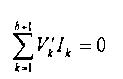
여기서, Vk와 Vk'는 부식전과 부식후의 분기회로에 대한 전압이며 Ik와 Ik'는 부식전과 부식후의 분기회로에 대한 전압이다. 측정량을 설정할 때 접지선 망에 주입한 전류는 Io이다.Where Vk and Vk 'are the voltages for the branch circuits before and after corrosion and Ik and Ik' are the voltages for the branch circuits before and after corrosion. When setting the measurand, the current injected into the ground wire network is Io.

또한, Iij=Iij'=Io이며, 다음과 같다.In addition, Iij = Iij '= Io, which is as follows.

![]()
![]()
식(1)、식(4) 및 식(5)을 각각 식(6)에 치환하면,When formula (1), formula (4) and formula (5) are replaced with formula (6),

(7) (7)
이를 간단하게 한 후 즉 다음과 같은 식을 얻는다.After simplifying this, we get

이로써, 다음과 같이 저항을 측정한 수학식을 얻을 수 있다.As a result, an equation in which resistance is measured can be obtained as follows.

접지선 망 각 구간의 도체 저항수치와 접지선 망 접지 도선 전기함수 사이의 수학 관계는 하나의 비선형 관계이다. 일반적으로 측정하여 얻은 접지 도선 사이의 전기함수의 독립적인 데이터는 접지선 망의 도전체 수보다 적다. 그리하여 반드시 미정 비선형 방정식의 풀이문제를 고려하여야 한다. 접지선 망 각 구간 도전체 저항의 변화로 일어난 도선 사이의 전기 함수값의 변화는 그리 뚜렷하지 않으므로 그 계산 결과는 측정오차에 대하여 아주 민감하다. 이론상 이것은 하나의 엄중한 병태 문제이므로 반드시 일정한 방법으로 극복하여 계산 결과가 측정오차에 미치는 민감도를 저하시켜야 한다. 그 외에 측정치는 항상 오차 등 구체적인 문제가 존재하므로 반드시 하나의 신속하고 정확하며 잡음 방지 능력이 강하고 행렬 병태 영향을 극복하는 계산방법을 구축하여야 한다.The mathematical relationship between the conductor resistance values of each section of the ground wire network and the electrical function of the ground wire network is a nonlinear relationship. In general, the independent data of the electrical function between the measured ground leads is less than the number of conductors in the ground wire network. Thus, we must consider the problem of solving the undefined nonlinear equations. The change in the electrical function value between the conductors caused by the change in the conductor resistance in each section of the ground wire network is not so obvious that the calculation results are very sensitive to the measurement error. In theory, this is a serious condition problem and must be overcome in some way to reduce the sensitivity of the calculation results to measurement errors. In addition, since measurement values always have specific problems such as errors, it is essential to establish a calculation method that overcomes the effects of matrix pathologies.
앞에서 유도한 수학 방식에 대하여 본 발명에서는 최적화의 방법을 이용하여 풀이하였으며 여기에서는 2차 계획법을 모색하여 일정한 제약조건이 있는 최적화 풀이방식을 만족시켰다. 각종 수학 계획방법의 비교를 통하여 본 발명에서는 2차 계획계산법 중의 리차드슨(Richardson) 방법을 채용하였다. 모든 방정식 중의 오차를 동시에 교정하기 위하여 제일 간단한 SIRT 계산법(Simultaneous Iterative Reconstruction Techniques)를 이용하였으며 그 행렬 표현 방식은 다음과 같다.The present invention is solved using the optimization method in the present invention, and here, the quadratic programming method is explored to satisfy the optimization solution with certain constraints. Through comparison of various mathematical planning methods, the present invention employs the Richardson method of the second plan calculation method. In order to correct errors in all equations at the same time, the simplest SIRT (Simultaneous Iterative Reconstruction Techniques) was used.

이에 상응한 함수는 다음과 같다.The equivalent function is
![]()
![]()
대응한 행렬 D는 한 쌍의 코너 행렬이며 그 제 i 번째 원소 Di는 다음과 같다. The corresponding matrix D is a pair of corner matrices whose i th element Di is

행렬 M의 모든 분량이 모두 부의 값이 아니므로(non-negative) 이 계산법은 한군데에 수렴한다.Since all quantities of the matrix M are non-negative (non-negative), this calculation converges in one place.
본 발명은 앞에서 절약한 수학방식 및 수치계산 방법 등에 의하여 접지선 망 부식 진단 소프트웨어를 작성하였다. 이 소프트웨어는 전체가 도형화면이며 조작이 간편하여 접지선 망의 도전체 데이터만 입력하면 프로그램이 자동으로 위상구조도, 측정 방안 도면을 생성하며 프로그램이 각 가용한 노드 측정 데이터 문서를 읽은 후 계산을 통하여 고장 구간을 파악할 수 있으며 또 직관적으로 도형에서 표현한다. 도 4는 진단 소프트웨어 공정 흐름도이다. 그 기본과정은 먼저 접지선 망의 위상구조파일*.brh를 읽고 접지선 망의 위상구조에서 접지선 망 부식을 파악하는 측정방안을 확정한다. 측정방안에 의하여 각 접지 도선 사이의 입력저항과 전이저항을 측정하여 측정문서 *.msr를 얻는다. 아래의 계산순서는 위상구조 및 측정결과에 의하여 각 구간의 도전체의 부식 및 단절을 분석한 상황이다. 파악방정식의 최적화 분석에 의하여 각 구간 도전체의 저항치 Rk를 얻는다. 만약 분석결과가 규정한 정밀도 요구에 도달하면 분석 계산을 정지하고 계산결과 Rk를 *.out로 저장한다. 임계치에 의하여 각 구간의 도전체의 단절 여부를 판단하며 각 구간의 도전체의 부식 정도를 계산하고 *.dia로 저장하고 분석 결과를 내보낸다.According to the present invention, a ground wire mesh corrosion diagnosis software is prepared by using a mathematical method and a numerical method. This software is a graphic screen in its entirety and is easy to operate, so if you input only the conductor data of the ground wire network, the program will automatically generate the topology diagram and measurement plan drawing. The fault section can be identified and intuitively represented in the figure. 4 is a diagnostic software process flow diagram. The basic procedure first reads the topology file *. Brh of the ground network, and then determines the measurement to identify the ground network corrosion in the ground structure of the ground network. Measure the input resistance and transition resistance between each ground lead by the measurement method and obtain the measurement document * .msr. The following calculation procedure is based on the analysis of corrosion and disconnection of conductors in each section based on the phase structure and measurement results. The resistance value Rk of each section conductor is obtained by optimization analysis of the grasping equation. If the analysis result reaches the specified precision request, the analysis calculation is stopped and the result Rk is stored as * .out. Judging the disconnection of the conductors in each section based on the threshold, calculate the corrosion degree of the conductors in each section, save it as * .dia, and export the analysis result.
원리상 단절 지점을 일종의 특수형식의 부식으로 보기 때문에 부식 정도가 얼마만큼의 크기로 될 경우 도전체 부식 단절로 보아야 하는지 고려해야 한다. 접지선 망의 접지 도선 사이의 전기함수의 측정치에서 얻은 접지선 망 각 구간 도전체 전기저항계산치와 실제수치는 절대치에서 항상 일정한 오차가 존재한다. 각 구간의 도전체 저항 계산치 사이의 상대치만이 고장 점의 판단에 의의가 있다. 그러므로 반드시 이러한 저항치의 분포상황에 의하여 자동으로 단절 지점과 미 단절 지점 사이의 저항 한계를 정하고 임계치 판단 근거로 확정해야 한다. 본 발명은 대량 의 모의 계산을 통하여 인공 신경망을 이용하여 서로 다른 허용 상황에서의 임계치 방식을 구축하였다.Since the point of disconnection is, in principle, regarded as a special type of corrosion, it is necessary to consider how much corrosion should be considered as a conductor corrosion breakdown. There is always a constant error in the absolute value of the electrical resistance calculation and the actual value of the conductor in each section of the ground wire network obtained from the measurement of the electrical function between the ground conductors of the ground wire network. Only the relative value between the conductor resistance calculations in each section is meaningful in determining the failure point. Therefore, the resistance limit between the disconnection point and the non-disconnection point must be automatically determined based on the distribution of these resistance values, and it must be confirmed based on the threshold judgment. The present invention establishes the threshold method in different permissible situations using artificial neural network through a large amount of simulation.
접지선 망 파악 시 실제 시공시의 도면과 망의 위상 구조 사이에 반드시 일정한 차이가 있으며 케이블 홈의 영향 등이 존재할 것이다. 분석을 통하여 이러한 허용으로 인한 파악 오차는 크지 않으므로 단절 지점에 대한 영향은 임계치 조절을 통하여 해결할 수 있다는 것을 표명하였다. 파악시스템의 다른 한 부분은 접지선 망 접지 도선 사이의 미세전기함수(입력저항 또는 전이저항)를 정밀하게 측정하는 측정시스템이다. 접지 도선 사이의 입력저항은 mΩ 레벨이며 이 파악시스템은 외부 방해가 존재하는 상황에서 mΩ 레벨의 작은 저항을 정밀하게 측정하는 문제를 해결하였다. 본 발명에서 설계한 작은 저항 미세 측정 장치는 외부 방해 하에 디지털화로 정확하게 측정하는 성능을 가지고 있다. 그 원리는 접지선 망 접지 도선 사이에 큰 전류(20~30A)를 주입하여 신호와 잡음의 비례를 높여 도선사이의 전위차 및 입력전류를 측정하여 입력저항을 얻거나 기타 도선 사이의 전위차를 측정하여 전이저항을 얻는다. 측정 장치가 변전소에서 정상적으로 운행할 경우 접지선 망에 대한 부식을 판단할 경우 전극환경이 아주 악화되는 경우를 고려하여 측정 장치에 일련의 통용 방해 방지조치를 취하여 단일 칩 컴퓨터 및 단일 칩 컴퓨터 프로그램의 방해방지 능력을 보증하였다. 접지선 망 부식판단시스템 측정 장치 부분의 기본 성능은 방해 작용 하의 작은 신호에 대하여 정확히 검측하는 것이다. 그리하여 설계 전체 전기회로에는 과전압보호、레인지 전환、샘플 채취/유지、A/D、디지털 메인 보 드 등 몇 개 모듈부분이 포함된다. 만약 모든 접지 도선 사이의 전기함수를 모두 측정한다면 첫째는 작업량이 크고 둘째는 어떤 측정결과는 중복될 수 있다. 그러므로 본 발명은 진단 소프트웨어에 메인요소분석원리의 측정방안에 의하여 자동 확정방식을 추가하였다. 접지선 망의 위상구조 및 접지 도선의 위치에 진단 소프트웨어를 입력 한 후 분석을 통하여 측정이 필요한 전기함수의 접지 도선 번호를 정하며 측정방안을 제공한다.When grasping the ground wire network, there will be a certain difference between the drawing of the actual construction and the phase structure of the network, and there will be the influence of the cable groove. The analysis indicated that the grasping error due to this tolerance is not so large that the impact on the break point can be resolved by adjusting the threshold. Another part of the grasping system is a measuring system that precisely measures the microelectrical function (input resistance or transition resistance) between the ground wire and the ground lead. The input resistance between the ground leads is in the mΩ level, and this grasp system solves the problem of precisely measuring small resistances in the mΩ level in the presence of external disturbances. The small resistance micro-measuring device designed in the present invention has the capability of accurately measuring digitally under external interference. The principle is to inject a large current (20 ~ 30A) between ground wires and ground wires to increase the proportion of signal and noise to measure the potential difference between the wires and the input current to obtain input resistance or to measure the potential difference between other wires. Get In case of normal operation of the measuring device in the substation, when the corrosion of the ground wire network is judged, taking into account the case where the electrode environment is very deteriorated, a series of common anti-blocking measures are taken in the measuring device to prevent the interruption of the single chip computer and the single chip computer program. Guaranteed ability. The basic performance of the ground wire mesh corrosion determination system measurement device is to accurately detect small signals under disturbance. Thus, the entire electrical circuit of the design contains several module parts: overvoltage protection, range switching, sampling / maintenance, A / D, digital main board. If all electrical functions between all ground leads are measured, firstly the workload is large and secondly some measurement results may overlap. Therefore, the present invention adds an automatic confirmation method to the diagnostic software by measuring the main element analysis principle. After inputting the diagnostic software into the ground structure of the ground wire network and the position of the ground lead, analysis and the ground lead number of the electric function to be measured are provided.
본 발명의 변전소 접지선 망 부식 및 단절 지점의 파악방법 및 측정 방법、파악시스템을 실시예와 결합한 첨부도면에 대한 설명은 다음과 같다. 본 실시예는 새로 건축한 220 kV 변전소에 대하여 단절 지점 파악 실험을 진행한 것이다. 실험 시 인공으로 접지선 망의 한 라인의 도전체를 절단하였다. 본 실시예의 변전소 접지선 망의 부식 및 단절 지점을 파악하는 조작순서는 다음과 같다.The description of the attached drawings in which the substation ground wire network corrosion and disconnection points of the present invention, the method of measuring and measuring the detection system, combined with the embodiment is as follows. In this embodiment, the disconnection point identification experiment was conducted for the newly constructed 220 kV substation. In the experiment, artificially cut a conductor of one line of the ground wire network. The operation sequence for identifying the corrosion and disconnection points of the substation ground wire network of the present embodiment is as follows.
단계 1 측정방안 확정: 접지선 망의 위상구조 및 접지 도선의 위치를 진단 소프트웨어에 입력시킨다. 어느 부분의 접지 도선 사이의 입력저항과 전이저항을 측정할지를 확정한다. Step 1 Determine the measurement method: Enter the phase structure of the ground wire network and the position of the ground lead into the diagnostic software. Determine which part of the ground lead between the input and transition resistors will be measured.
단계 2 : 단계 1에서 확정한 측정방안에 의하여 입력저항 또는 전이저항을 측정한다.Step 2: Measure the input resistance or transition resistance by the measurement method established in step 1.
(a) 접지선 망에 큰 직류전류(25A정도)를 주입한다. 25A정도의 직류 교차 전류 소스를 외부 증가 전원으로 하여 접지선 망의 어느 두 라인의 접지 도선 사이에 가한다. 공사현장에서 교차 전류 소스를 찾기 비교적 힘들 경우 180A/h의 배터리로 대신할 수 있다. 직류전원을 사용하면 교류 전원의 전세(전기세력)를 감응하는 영향을 피할 수 있다. 전류를 가하면 접지선 망 도전체중의 방해신호를 억제할 수 있다.(a) Inject a large DC current (around 25A) into the ground wire network. A dc cross-current source of approximately 25 amperes shall be applied between the ground leads of any two lines of the ground wire network with an external incremental supply. If it is relatively hard to find a cross-current source at a construction site, it can be replaced with a 180 A / h battery. The use of a DC power source avoids the influence of the AC power. Applying a current can suppress a disturbance signal in the ground wire conductor.
(b) 측정을 통하여 각 도선 사이의 전압을 얻는다. 측정시스템은 외부 신호에 대하여 샘플 채취/유지하는 측정방식을 이용하여 멀티채널신호의 동일순간의 수치를 유지하고 전압U와 I를 동시에 측정하여 U, I의 동일순간의 수치를 얻을 수 있다. 그리하여 배터리 전압의 전하 등 불안정한 요소의 영향을 해소할 수 있으며 두 접지 도선 사이의 정확한 입력저항을 얻을 수 있다.(b) Measure the voltage between each wire. The measurement system maintains the same instantaneous value of the multi-channel signal and measures the voltage U and I at the same time by using the measurement method of sampling / maintaining the external signal, thereby obtaining the same instantaneous value of U and I. Thus, the effects of unstable factors such as the charge of the battery voltage can be eliminated, and accurate input resistance between the two ground leads can be obtained.
(c) 측정결과는 파악 분석 소프트웨어와 통신하여 직접 진단 소프트웨어에 전송한다.(c) Measurement results are communicated with grasp analysis software and sent directly to diagnostic software.
단계 3 : 접지선 망 각 구간 도전체의 부식 및 단절상황을 확인한다.Step 3: Check the corrosion and disconnection status of the conductors in each section of the ground wire mesh.
(a) 부식 후의 접지선 망 각 구간 도전체의 저항을 확인한다 : 편제한 진단 소프트웨어(도4)를 통하여 측정하여 얻은 접지선 망 접지 도선 사이의 입력저항 또는 전이저항 및 입력한 접지선 망 위치구조를 통하여 접지선 망 각 구간 도전체의 저항을 얻는다.(a) Check the resistance of the conductors in each section of the grounded wire network after corrosion: through the input resistance or transition resistance between the grounded wire grounding conductors measured by the prepared diagnostic software (Fig. 4) and the input grounded wire network position structure. The resistance of the conductor in each section of the ground wire network is obtained.
(b) 각 구간 도전체는 측정구조를 통하여 분석하여 얻은 각 도전체의 저항과 계산 및 분석하여 얻은 설계저항수치와 비교를 진행한다. 부식 후(또는 새 접지선 망 공사완료 후) 각 구간의 도전체 저항의 변화상황에 의하여 임계치에 E라 각 구간 도전체의 단절 여부를 판단하며 부식 정도를 판단한다. 만약 새 접지선 망일 경 우에는 용접불량 또는 용접누락상황을 판단한다. 접지선 망을 설계, 준공한 후 각 구간 도전체의 길이、단면 면적 및 재료를 이미 확인하였기 때문에 그 설계 저항치는 일정한 것이다. 그러므로 계산해 낸 각 도전체의 저항치의 차이는 부식 정도의 차이를 대표한다.(b) Conductors in each section are compared with the resistance of each conductor obtained through the measurement structure and the design resistance value obtained by calculation and analysis. After the corrosion (or after the completion of the construction of the new ground wire network), depending on the change of conductor resistance in each section, it is judged whether or not the conductor is disconnected in each section by the threshold value E. If it is a new ground wire network, it is judged that there is a weld failure or a missing welding condition. After designing and completing the ground wire network, the length, cross-sectional area and material of the conductors in each section have already been checked, so the design resistance is constant. Therefore, the difference in the resistance of each conductor calculated represents the difference in the degree of corrosion.
본 실시예의 측정장치 구조는 도 5에 표시된 바와 같다. 첫 번째 모듈은 입력전기회로이며 전압제한 보호와 확대회로 두 개 부분이 포함된다. 적당한 확대전기회로를 선택하여 신호의 변조를 감소시켜 운행하는 영점 변이(null shift)와 워밍 변이(Warming Shift)를 엄격히 제어한다.The measuring device structure of this embodiment is as shown in FIG. The first module is the input electrical circuit and includes two parts: voltage limit protection and expansion circuit. By selecting the appropriate expansion circuit, the modulation of the signal is reduced to tightly control the moving and warming shifts.
두 번째 모듈은 멀티채널 모의수치전환회로이며 멀티채널스위치、샘플 채취/ 유지、레인지 전환 및 모듈전환이 포함된다. 각 회로의 매개 샘플 채취의 순간 모이 측정치를 데이터 량으로 전환하여 단일 칩 컴퓨터 메인보드에 전송한다.The second module is a multichannel simulation switch circuit that includes multichannel switches, sampling / maintenance, range switching and module switching. The instantaneous collection of each sample of each circuit is converted into data quantities and sent to the single-chip computer motherboard.
세 번째 모듈은 단일 칩 컴퓨터의 핵심 회로이며 데이터처리、시스템복원과 데이터통신이 포함된다. 미세 처리기가 모듈을 전환한 결과를 얻은 후 미리 설계한 계산법에 따라 이에 대하여 계산을 진행하며 계산결과를 컴퓨터에 전송한다. 상술한 모듈은 모두 시장에서 판매하는 제품을 사용할 수 있다. The third module is the core circuit of a single chip computer and includes data processing, system restoration and data communication. After the microprocessor obtains the result of switching the module, the microprocessor performs the calculation according to the predesigned calculation method and transmits the calculation result to the computer. All of the above-described modules can use products sold in the market.
도6은 본 실시예의 측정 장치 단일 칩 컴퓨터의 소프트웨어 흐름도이다. 먼저 요구사항에 의하여 측정해야 할 도선 사이에 직류전류를 가하고 측정 도선 사이 전위차의 측정 도선을 배치한 후 측정과정은 먼저 측정시스템의 각 부분을 초기화한 후 컴퓨터에서 측정시작명령을 내리고 측정시간 거리, 데이터 샘플 채취, 모듈전환을 진행한다. 만약 측정결과가 이상일 경우 다시 샘플 채취를 한다. 모두 300 회 샘플 채취하며 샘플 채취가 끝난 후 측정결과에 대하여 수정하며 수정한 후의 결과는 본체의 진단 소프트웨어의 측정문서*.msr에 보낸다.Fig. 6 is a software flowchart of the measuring device single chip computer of this embodiment. First, the DC current is applied between the conductors to be measured according to the requirements, and the measurement conductors of the potential difference between the measurement conductors are placed.The measurement process first initializes each part of the measurement system, and then gives a measurement start distance command from the computer. Proceed with data sampling and module conversion. If the result is abnormal, take another sample. All 300 samples are taken. After sampling, the measurement results are corrected and the results are sent to the measurement document * .msr of the diagnostic software.
본 실시예에서 측정 장치는 박스를 통하여 정밀한 전자스크린을 채취하고 하드웨어 시스템은 모의 전기회로와 데이터 전기회로의 분리、또 데이터 회로 칩의 전원 분리、접지선을 굵게 하고 접지선으로 감싸며 각 수행 모듈을 분리하고 “가드(gurard)”전기 회로를 사용하는 등 조치를 취한다. 소프트웨어설계에서는 메인 프로그램 입구에 소프트웨어시간을 연장하고 I/O 포트를 프로그래밍할 수 있는 기능을 추가하여 반복 재생、제어 명령 반복 실행、명령중복、데이터 웨이브 필터링、데이터 처리 등을 설정하는 조치를 취하여 전체적인 저항능력을 확보하였다. 이는 모두 자주 사용하는 마이크로 컴퓨터 시스템 방해방지 조치이다. In this embodiment, the measuring device takes a precise electronic screen through the box, and the hardware system separates the simulation circuit and the data electrical circuit, separates the power of the data circuit chip, thickens the ground line, surrounds the ground line, and separates each performance module. Take measures, such as using “gurard” electrical circuits. The software design adds the ability to extend the software time at the entrance of the main program and program the I / O port, taking steps to set repeat play, control command repeat execution, command duplication, data wave filtering, data processing, etc. Secured resistance. All of these are anti-jamming measures that are frequently used.
본 실시예의 접지선 망 일부분 구조도는 도 7과 같다. 실험 전에 5-6의 도전체를 절단한다. 진단 소프트웨어는 직접 그 결과를 도형방식으로 도면8과 같이 내보낸다. 도면 중의 회색은 부식 정도를 표시하며 검은색은 단절현상을 표시한다. 파악결과 문서에 의하여 각 수평분기회로의 계산 데이터를 도 9와 같이 나타낸다. 도면 중 12 분기 회로는 도 7에서 확인한 5-6 도전체이다. 설정저항 증대배수가 1.2 이하일 경우 도전체는 부식이 발생하지 않으며 설정저항증대배수가 3 이상일 경우 도전체에는 단절이 발생한다. 도면 6에서 고장을 5-6분기회로라고 판단할 수 있으며 설계 결과와 완전 일치한다. 현장 측정결과는 사람들로 하여금 만족하게 한 다. 측정데이터와 진단 소프트웨어를 통하여 분석하며 분석하여 얻은 단절 지점 위치는 실제상황과 일치하다. 실험결과는 사람들의 요구를 만족시키며 본 발명에서 제출한 접지선 망 부식 및 단절 지점 파악원리와 방법의 정확성 및 시스템의 가능성을 검증하였다. 그 외에 접지선 망 부식파악결과와 실제 접지선 망 부분을 파헤쳐 얻은 실제 접지 도전체의 부식상황은 기본적으로 일치하며 오차는 8% 이내이다. A partial structural diagram of the ground wire network of this embodiment is shown in FIG. 7. Cut 5-6 conductors before the experiment. The diagnostic software directly exports the result as shown in FIG. Gray in the figure indicates the degree of corrosion and black indicates the breakage phenomenon. The calculation data of each horizontal branch circuit is shown in Fig. 9 according to the grasping result document. 12 branch circuits in the figure are 5-6 conductors identified in FIG. If the set resistance increase multiplier is 1.2 or less, the conductor will not be corroded. If the set resistance increase multiplier is 3 or more, the conductor will be disconnected. In Figure 6, the fault can be considered as a 5-6 branch circuit and is in full agreement with the design results. Field measurements make people happy. The break point location obtained by analyzing and analyzing the measured data and diagnostic software is consistent with the actual situation. The experimental results satisfy the needs of people and verify the grounding network corrosion and disconnection point grasping principle, the accuracy of the method and the possibility of the system. In addition, the results of the ground wire mesh corrosion detection and the actual ground conductor corrosion conditions obtained by digging the ground wire mesh part basically coincide, and the error is within 8%.
본 발명의 예시적인 실시예들은 첨부 도면을 참조하여 기술되었지만, 본 발명은 이러한 정확한 실시예들로만 한정되는 것이 아니라, 다양한 수정 및 변경이 다음의 첨부된 청구 범위에 기재된 본 발명의 사상 및 범위 내에서 본 기술 분야의 당업자에게 자명하다. While exemplary embodiments of the invention have been described with reference to the accompanying drawings, the invention is not limited to these exact embodiments, but various modifications and changes are intended to be within the spirit and scope of the invention as set forth in the following appended claims. It is apparent to those skilled in the art.
본 발명에서 설계한 접지선 망의 미세입력저항 또는 전이저항을 측정하는 단일 칩 컴퓨터와 윈도우 기초 위에 도형화한 진단 소프트웨어는 하나의 파악시스템을 구축한다. 컴퓨터를 핵심으로 집중측정 량과 계산을 일체로 한 접지선 망 단절 지점 및 부식 파악시스템이다. 즉 접지선 망 단절 지점 및 부식파악과 새 접지선 망의 검사를 진행하는 공업 컴퓨터 단층 촬영기이다. 본 발명방법을 이용한 파악 결과는 실제부분을 파헤쳐 얻은 실제 접지 도전체의 부식상황과 기본적으로 일치하며 오차는 8% 이내이며 접지 망 도전체의 단절 상황을 효율적으로 파악할 수 있다. 비교적 높은 정확도를 가지고 있어서 현장 측정의 요구사항을 만족시킬 수 있다. 이러한 부식파악방법은 간단하고 정확하며 현장운행조건의 제한을 받지 않으며 정전하지 않고 파헤치지 않는 상황 하에 접지선 망의 고장에 대하여 효율적으로 판단하여 공사 품질을 보증하고 접지선 망의 은폐된 문제점을 해소함으로써 접지선 망의 보호와 과학적인 관리를 도와준다. 중대사고의 발생을 미리 방지할 수 있어 아주 큰 경제 효익과 사회 효익이 있다. 본 발명은 접지선 망 부식 검사 시스템뿐만 아니라 접지 공사 준공 후 시공 중의 접지선 망 용접누락과 용접불량에 대하여 효율적으로 검사하는 수단으로도 된다. 즉 접지선 망의 용접불량과 용접누락상황을 파악하고 분석하여 접지선 망 시공의 공사 품질을 확보한다. 동시에 금속파이프(물파이프, 기체파이프, 오일파이프)의 부식파악에도 사용할 수 있다.The single chip computer for measuring the micro input resistance or the transition resistance of the ground wire network designed in the present invention and the diagnostic software plotted on the base of the window construct a single grasping system. It is a ground wire network break point and corrosion detection system that combines centralized measurement and calculation with a computer as the core. In other words, it is an industrial computed tomography machine that checks ground wire break points and checks for corrosion and new ground wire networks. The grasping result using the method of the present invention basically matches the corrosion situation of the actual ground conductor obtained by digging the actual part, and the error is within 8%, and it is possible to efficiently identify the disconnection state of the ground network conductor. It has a relatively high accuracy to meet the requirements of field measurements. This corrosion detection method is simple and accurate, and is not limited by the field operating conditions, and efficiently judges the failure of the ground wire network under the condition of not breaking down without power failure to guarantee construction quality and solve the concealed problem of the ground wire network. Help protect and scientifically manage your network. Major accidents can be prevented in advance, resulting in very large economic and social benefits. The present invention is not only a ground wire mesh corrosion inspection system but also a means for efficiently inspecting a ground wire mesh weld leakage and a weld defect during construction after completion of a ground construction. In other words, the quality of the construction of the ground wire network is secured by identifying and analyzing the welding defect and the welding leakage situation of the ground wire network. At the same time, it can be used for corrosion detection of metal pipe (water pipe, gas pipe, oil pipe).
Claims (4)
Priority Applications (1)
| Application Number | Priority Date | Filing Date | Title |
|---|---|---|---|
| KR1020050123788A KR100657855B1 (en) | 2005-12-15 | 2005-12-15 | A method for detecting grounded network erosion and broken point of substation |
Applications Claiming Priority (1)
| Application Number | Priority Date | Filing Date | Title |
|---|---|---|---|
| KR1020050123788A KR100657855B1 (en) | 2005-12-15 | 2005-12-15 | A method for detecting grounded network erosion and broken point of substation |
Publications (1)
| Publication Number | Publication Date |
|---|---|
| KR100657855B1 true KR100657855B1 (en) | 2006-12-21 |
Family
ID=37814694
Family Applications (1)
| Application Number | Title | Priority Date | Filing Date |
|---|---|---|---|
| KR1020050123788A KR100657855B1 (en) | 2005-12-15 | 2005-12-15 | A method for detecting grounded network erosion and broken point of substation |
Country Status (1)
| Country | Link |
|---|---|
| KR (1) | KR100657855B1 (en) |
Cited By (11)
| Publication number | Priority date | Publication date | Assignee | Title |
|---|---|---|---|---|
| CN102540013A (en) * | 2011-12-27 | 2012-07-04 | 广东电网公司韶关供电局 | Transformer substation grounding network frequency response test device |
| CN102680820A (en) * | 2012-05-08 | 2012-09-19 | 湖州电力局 | Automatic testing and diagnosing system for corrosion fault points of grounding grid of substation |
| CN105137279A (en) * | 2015-07-16 | 2015-12-09 | 吉林大学 | Grounding grid breakpoint diagnostic method based on transient electromagnetic abnormal ring principle |
| CN105182169A (en) * | 2015-10-10 | 2015-12-23 | 国网山西省电力公司临汾供电公司 | Defect screening detection method and apparatus of grounding network upper guide body wire |
| CN105242173A (en) * | 2015-09-14 | 2016-01-13 | 吉林大学 | Frequency domain electromagnetic method-based grounding grid fault automatic diagnosis method |
| CN105425049A (en) * | 2015-10-29 | 2016-03-23 | 国网浙江省电力公司台州供电公司 | Method of testing geodetic network earthing resistance |
| CN107615086A (en) * | 2015-04-15 | 2018-01-19 | 库珀技术公司 | For system, the method and apparatus of the integrality for diagnosing electric conductor bearing system |
| US10114061B2 (en) | 2016-11-28 | 2018-10-30 | Kohler Co. | Output cable measurement |
| CN112130026A (en) * | 2020-09-22 | 2020-12-25 | 福州大学 | MMC-HVDC single-pole grounding fault positioning method based on wavelet packet energy entropy and DBN |
| CN113687191A (en) * | 2021-09-28 | 2021-11-23 | 国网上海市电力公司 | Grounding grid fault diagnosis method based on combination of electrical impedance imaging technology and electric network theory method |
| KR102506177B1 (en) | 2022-11-17 | 2023-03-06 | (주)동화이엔지 | Ground management system for substation |
Citations (5)
| Publication number | Priority date | Publication date | Assignee | Title |
|---|---|---|---|---|
| JPS59200974A (en) | 1983-04-28 | 1984-11-14 | Chubu Electric Power Co Inc | Device for measuring earthing resistance |
| KR20000037146A (en) * | 2000-04-10 | 2000-07-05 | 정재기 | A new technical method and equipment for the grounding resistance measurement on power service |
| KR20020028168A (en) * | 2002-02-20 | 2002-04-16 | 나용균 | Sing line existence and nonexistence check method of ground connection rail track |
| KR20050001898A (en) * | 2003-06-26 | 2005-01-07 | 학교법인 인하학원 | A variable frequency inverter-type high power ground resistance measuring device and measuring method based on PC |
| KR20050021668A (en) * | 2003-08-25 | 2005-03-07 | 한국전력공사 | Ground resistor analysis system |
-
2005
- 2005-12-15 KR KR1020050123788A patent/KR100657855B1/en active IP Right Grant
Patent Citations (5)
| Publication number | Priority date | Publication date | Assignee | Title |
|---|---|---|---|---|
| JPS59200974A (en) | 1983-04-28 | 1984-11-14 | Chubu Electric Power Co Inc | Device for measuring earthing resistance |
| KR20000037146A (en) * | 2000-04-10 | 2000-07-05 | 정재기 | A new technical method and equipment for the grounding resistance measurement on power service |
| KR20020028168A (en) * | 2002-02-20 | 2002-04-16 | 나용균 | Sing line existence and nonexistence check method of ground connection rail track |
| KR20050001898A (en) * | 2003-06-26 | 2005-01-07 | 학교법인 인하학원 | A variable frequency inverter-type high power ground resistance measuring device and measuring method based on PC |
| KR20050021668A (en) * | 2003-08-25 | 2005-03-07 | 한국전력공사 | Ground resistor analysis system |
Cited By (13)
| Publication number | Priority date | Publication date | Assignee | Title |
|---|---|---|---|---|
| CN102540013A (en) * | 2011-12-27 | 2012-07-04 | 广东电网公司韶关供电局 | Transformer substation grounding network frequency response test device |
| CN102680820A (en) * | 2012-05-08 | 2012-09-19 | 湖州电力局 | Automatic testing and diagnosing system for corrosion fault points of grounding grid of substation |
| CN107615086A (en) * | 2015-04-15 | 2018-01-19 | 库珀技术公司 | For system, the method and apparatus of the integrality for diagnosing electric conductor bearing system |
| CN105137279A (en) * | 2015-07-16 | 2015-12-09 | 吉林大学 | Grounding grid breakpoint diagnostic method based on transient electromagnetic abnormal ring principle |
| CN105242173A (en) * | 2015-09-14 | 2016-01-13 | 吉林大学 | Frequency domain electromagnetic method-based grounding grid fault automatic diagnosis method |
| CN105182169A (en) * | 2015-10-10 | 2015-12-23 | 国网山西省电力公司临汾供电公司 | Defect screening detection method and apparatus of grounding network upper guide body wire |
| CN105425049A (en) * | 2015-10-29 | 2016-03-23 | 国网浙江省电力公司台州供电公司 | Method of testing geodetic network earthing resistance |
| US10114061B2 (en) | 2016-11-28 | 2018-10-30 | Kohler Co. | Output cable measurement |
| CN112130026A (en) * | 2020-09-22 | 2020-12-25 | 福州大学 | MMC-HVDC single-pole grounding fault positioning method based on wavelet packet energy entropy and DBN |
| CN112130026B (en) * | 2020-09-22 | 2021-09-28 | 福州大学 | MMC-HVDC single-pole grounding fault positioning method based on wavelet packet energy entropy and DBN |
| CN113687191A (en) * | 2021-09-28 | 2021-11-23 | 国网上海市电力公司 | Grounding grid fault diagnosis method based on combination of electrical impedance imaging technology and electric network theory method |
| CN113687191B (en) * | 2021-09-28 | 2024-04-12 | 国网上海市电力公司 | Grounding grid fault diagnosis method based on combination of electrical impedance imaging technology and electrical network theory method |
| KR102506177B1 (en) | 2022-11-17 | 2023-03-06 | (주)동화이엔지 | Ground management system for substation |
Similar Documents
| Publication | Publication Date | Title |
|---|---|---|
| KR100657855B1 (en) | A method for detecting grounded network erosion and broken point of substation | |
| KR20070063709A (en) | A system for detecting grounded network erosion and broken point of substation | |
| CN1110707C (en) | Diagnosis method of earth screen corrosion and breakpoint of electric substation and its measurement and diagnosis system | |
| CN101493491B (en) | Substation ground network defect synthesis diagnosis method and diagnosis system thereof | |
| CN102928704B (en) | Intelligent diagnosis method for corrosion failure point of transformer substation grounding grid | |
| CN100580464C (en) | Large-scale grounding network detection technology and detection system for power plant and transformer substation | |
| CN109765459B (en) | Single-phase earth fault positioning method and system based on in-situ study and judgment | |
| AU2020101683A4 (en) | Fault detection, location, and prediction within an electricity power transmission and distribution networks | |
| CN102495291A (en) | Impedance frequency response method for measuring corrosion state of grounding network of transformer substation | |
| CN104678246A (en) | Method and system for evaluating corrosion state of transformer substation grounding grid | |
| CN110261680B (en) | Method, device and system for detecting resistance parameters of grounding system and monitoring network | |
| CN104931853B (en) | A kind of grounding net of transformer substation corrosion diagnosis method based on surface potential distribution | |
| CN109580722A (en) | A kind of ground net corrosion monitoring method and device based on AC admittance method | |
| CN102680820A (en) | Automatic testing and diagnosing system for corrosion fault points of grounding grid of substation | |
| CN105467192B (en) | A kind of method for measuring current conversion station ground potential and rising | |
| CN105371742A (en) | Bushing tap pulse signal injection method-based transformer winding deformation detection device and method | |
| CN104833898A (en) | Substation grounding grid corrosion state evaluation method using M-sequence signal current | |
| CN103323694B (en) | A kind of grounding net of transformer substation conductor disappearance detection method | |
| CN104849620A (en) | Grounding grid fault diagnosis method based on BP neural network | |
| CN110780151A (en) | Large-scale grounding grid multi-channel rapid corrosion detection and plane imaging diagnosis method | |
| CN104062555B (en) | The discrimination method of distribution line high resistance earthing fault characteristic harmonics | |
| CN117535669A (en) | Fixed-point accurate cathode protection corrosion prevention method for grounding grid | |
| Liu et al. | Optimized corrosion diagnosis of large-scale grounding grid | |
| CN105425049A (en) | Method of testing geodetic network earthing resistance | |
| CN106841890B (en) | Fault diagnosis method in cross-connection box based on grounding current |
Legal Events
| Date | Code | Title | Description |
|---|---|---|---|
| A201 | Request for examination | ||
| N231 | Notification of change of applicant | ||
| A302 | Request for accelerated examination | ||
| E902 | Notification of reason for refusal | ||
| E701 | Decision to grant or registration of patent right | ||
| N231 | Notification of change of applicant | ||
| GRNT | Written decision to grant | ||
| FPAY | Annual fee payment |
Payment date: 20121129 Year of fee payment: 7 |
|
| FPAY | Annual fee payment |
Payment date: 20131204 Year of fee payment: 8 |
|
| FPAY | Annual fee payment |
Payment date: 20141208 Year of fee payment: 9 |
|
| FPAY | Annual fee payment |
Payment date: 20151201 Year of fee payment: 10 |
|
| FPAY | Annual fee payment |
Payment date: 20161128 Year of fee payment: 11 |
|
| FPAY | Annual fee payment |
Payment date: 20171201 Year of fee payment: 12 |
|
| FPAY | Annual fee payment |
Payment date: 20181203 Year of fee payment: 13 |
|
| FPAY | Annual fee payment |
Payment date: 20191202 Year of fee payment: 14 |