KR100629297B1 - Mechanical connection for open clamps - Google Patents
Mechanical connection for open clamps Download PDFInfo
- Publication number
- KR100629297B1 KR100629297B1 KR1020027000228A KR20027000228A KR100629297B1 KR 100629297 B1 KR100629297 B1 KR 100629297B1 KR 1020027000228 A KR1020027000228 A KR 1020027000228A KR 20027000228 A KR20027000228 A KR 20027000228A KR 100629297 B1 KR100629297 B1 KR 100629297B1
- Authority
- KR
- South Korea
- Prior art keywords
- hook
- clamp
- band portion
- clamping
- band
- Prior art date
Links
Images


Classifications
-
- F—MECHANICAL ENGINEERING; LIGHTING; HEATING; WEAPONS; BLASTING
- F16—ENGINEERING ELEMENTS AND UNITS; GENERAL MEASURES FOR PRODUCING AND MAINTAINING EFFECTIVE FUNCTIONING OF MACHINES OR INSTALLATIONS; THERMAL INSULATION IN GENERAL
- F16L—PIPES; JOINTS OR FITTINGS FOR PIPES; SUPPORTS FOR PIPES, CABLES OR PROTECTIVE TUBING; MEANS FOR THERMAL INSULATION IN GENERAL
- F16L33/00—Arrangements for connecting hoses to rigid members; Rigid hose connectors, i.e. single members engaging both hoses
- F16L33/02—Hose-clips
- F16L33/025—Hose-clips tightened by deforming radially extending loops or folds
-
- F—MECHANICAL ENGINEERING; LIGHTING; HEATING; WEAPONS; BLASTING
- F16—ENGINEERING ELEMENTS AND UNITS; GENERAL MEASURES FOR PRODUCING AND MAINTAINING EFFECTIVE FUNCTIONING OF MACHINES OR INSTALLATIONS; THERMAL INSULATION IN GENERAL
- F16L—PIPES; JOINTS OR FITTINGS FOR PIPES; SUPPORTS FOR PIPES, CABLES OR PROTECTIVE TUBING; MEANS FOR THERMAL INSULATION IN GENERAL
- F16L33/00—Arrangements for connecting hoses to rigid members; Rigid hose connectors, i.e. single members engaging both hoses
- F16L33/02—Hose-clips
- F16L33/035—Hose-clips fixed by means of teeth or hooks
-
- Y—GENERAL TAGGING OF NEW TECHNOLOGICAL DEVELOPMENTS; GENERAL TAGGING OF CROSS-SECTIONAL TECHNOLOGIES SPANNING OVER SEVERAL SECTIONS OF THE IPC; TECHNICAL SUBJECTS COVERED BY FORMER USPC CROSS-REFERENCE ART COLLECTIONS [XRACs] AND DIGESTS
- Y10—TECHNICAL SUBJECTS COVERED BY FORMER USPC
- Y10T—TECHNICAL SUBJECTS COVERED BY FORMER US CLASSIFICATION
- Y10T24/00—Buckles, buttons, clasps, etc.
- Y10T24/14—Bale and package ties, hose clamps
- Y10T24/1457—Metal bands
- Y10T24/1478—Circumferentially swagged band clamp
-
- Y—GENERAL TAGGING OF NEW TECHNOLOGICAL DEVELOPMENTS; GENERAL TAGGING OF CROSS-SECTIONAL TECHNOLOGIES SPANNING OVER SEVERAL SECTIONS OF THE IPC; TECHNICAL SUBJECTS COVERED BY FORMER USPC CROSS-REFERENCE ART COLLECTIONS [XRACs] AND DIGESTS
- Y10—TECHNICAL SUBJECTS COVERED BY FORMER USPC
- Y10T—TECHNICAL SUBJECTS COVERED BY FORMER US CLASSIFICATION
- Y10T24/00—Buckles, buttons, clasps, etc.
- Y10T24/14—Bale and package ties, hose clamps
- Y10T24/1457—Metal bands
- Y10T24/1482—Ratchet and tool tightened band clamp
Abstract
Description
본 발명은 클램프를 체결하기 위한 소성 변형 가능한 이어(ear)를 사용하는 소위 개방 클램프에 관한 것으로, 특히 하나의 밴드부에서 안내 기능을 수행하여 다른 밴드부의 적어도 하나의 개구에 결합되는 적어도 하나의 후크를 이용한 클램프의 밴드 중첩부에서의 기계식 연결체에 관한 것이다. The present invention relates to a so-called open clamp using a plastically deformable ear for fastening a clamp, in particular to at least one hook which engages in at least one opening of the other band part by performing a guiding function in one band part. A mechanical connector at the band overlap of the clamp used.
일반적으로 아연 도금강이나 스테인리스강인 밴드 재료로 제조되고, 클램프를 체결하기 위해 소성 변형 가능한 "외티커(Oetiker)" 이어를 사용하는 소위 개방 클램프는 오랫동안 상업적으로 판매되어 왔고 아주 성공적이다. 밴드 중첩부는 "외티커" 이어의 소성 변형에 의해 클램프를 체결하기 전에, 예컨대 스폿용접이나 양호하게는 외부 밴드 중첩부의 하나 이상의 개구에 결합하는 내부 밴드 중첩부의 하나 이상의 후크형 부재에 의해 기계적으로 연결되어야만 한다. 때로는 서스펜션 후크로도 불리고, 클램핑 밴드의 종방향으로 대체로 U자형으로 절결된 후 횡축에 대하여 클램핑 밴드로부터 구부러진 하나 이상의 소위 안내 후크는 이런 목적을 위해 오랫동안 사용되어 왔다. 도1 내지 도3은, 미국 특허 제3,321,811호에 개시된 바와 같이, 그러한 안내 후크(21)가 내부 밴드부(11b)로부터 경사지게 외향으로 연장되고 외부 클램핑 밴드 중첩부(11a)의 여러 개구(22) 중 하나와 결합하는 소위 개방 클램프를 도시한다. 비록 본 발명은 이론상으로는 체결이 개시되기 전에 기계식 연결체를 필요로 하는 모든 체결 기구에도 적용 가능하지만, 예컨대 미국 특허 제5,282,205호에서 설명된 바와 같이 일반적으로는 (도시되지 않은) 강화 홈이나 팬-형상 오목부가 제공된 브리지부(16)에 의해 상호 연결되고 일반적으로 외향 연장된 평행한 레그부(14, 15)로 구성되며, 일반적으로 도1의 도면 부호 13으로 표시된 소위 "외티커" 이어의 소성 변형에 의해 체결되는 개방 클램프와 사용될 때 특히 중요하고 유리하다. 단지 하나의 그러한 안내 후크(21)만을 사용하는 종래 기술의 기계식 연결체는 (도3의) 클램프 재개방 위치(21')로 후크(21)를 후방으로 구부리는 체결력을 인가하는 중에 기계식 연결체가 쉽게 재개방된다는 문제에 직면하게 된다. 후방으로 구부러지는 안내 후크로 인한 클램프의 재개방 용이성을 감소시키기 위해, 안내 후크(31)와 딥-드로잉된 지지 후크(32)(들)의 조합체가 미국 특허 제4,299,012호에서와 같은 클램프로서 제시되어 있으며, 이로 인해 이어(13)의 소성 변형에 의해 체결력이 가해질 때, 안내 후크(31)의 경사면을 따라 안내되는 외부 밴드부(11a)는 개구(35)에 지지 후크(32)를 확실히 결합시키기 위해 내부 밴드부(11b)쪽으로 당겨질 수 있다(도4). 또한, 이는 지지 후크에 의해 더 높은 체결력을 더 잘 흡수할 수 있도록 한다. 이런 종래 기술의 배열은 아주 성공적인 것으로 증명되었다. 하지만, 예컨대 공압식 공구를 사용함으로서 체결력의 증가 속도가 클램핑 밴드 재료, 클램핑 밴드의 두께 및 레버 아암을 결정하는 안내 후크의 길이에 따라 소정 값을 넘어서게 되면, 안내 후크는 밴드 중첩부들이 그들 각각의 개구에 지지 후크가 결합되도록 서로 충분히 근접하기 전에 후방으로 구부러질 수도 있다.So-called open clamps made of band material, which are generally galvanized or stainless steel, and which use plastically deformable "Oetiker" ears to fasten the clamps, have been commercially available for a long time and have been very successful. The band overlap is mechanically connected by means of one or more hooked members of the inner band overlap prior to engaging the clamp by plastic deformation of the "external ticker" ear, for example, spot welding or preferably to one or more openings of the outer band overlap. Should be. Sometimes referred to as suspension hooks, one or more so-called guide hooks that have been bent from the clamping band about the transverse axis after being cut into a generally U-shape in the longitudinal direction of the clamping band have long been used for this purpose. 1-3 show that such a
이런 개방 클램프는 편평한 강 밴드 재료로 제조되며, 일반적으로 "외티커" 이어의 소성 변형에 의해 체결이 개시되기 전에 호스 위에 설치하는 것과 안내 후크를 그 개구에 결합하는 것을 용이하게 하도록 어느 정도 원형으로 변형된다. 그러나, 이런 사전 변형은 스프링 응력이 클램핑 밴드에 쉽게 설정되도록 해서 클램핑 밴드를 보다 직선 형상으로 복귀시키도록 한다. 즉 안내 후크로부터 외부 밴드부(11a)의 결합 해제에 의해 클램프를 재개방하도록 한다. 따라서, 다른 기존의 문제점은 외부 밴드부(11a)가 스프링력을 받으면서 안내 후크의 자유 단부의 모서리 위에서 다시 외향으로 활주할 때 재개방되기 쉽다는 점이다. 이러한 위험은 안내 후크가 짧을수록 크다. 반면에, 안내 후크가 길수록, 안내 후크 재개방 위치로 후크를 구부리도록 된 레버 아암은 더 커진다. 이들 모순적인 효과를 상쇄시키기 위해, 이제까지는 도5의 21a로 도시된 바와 같이 안내 후크의 자유 단부를 구부리는 것이 제안되어 왔다. 이것은 문제점을 개선하지만 그러한 문제점을 완전히 제거하지는 못한다.These open clamps are made of flat steel band material and are generally rounded to some extent to facilitate installation over the hose and engagement of the guide hooks to their openings, prior to initiation of the fastening by plastic deformation of the "outer ticker" ear. Is deformed. However, this predeformation allows the spring stress to be easily set on the clamping band, thereby returning the clamping band to a more straight shape. That is, the clamp is reopened by disengaging the
본 발명은 후크-결합 개구가 제공된 외부 밴드부가 안내 후크의 자유 단부 위로 활주하여 이탈하는 것을 중지시킴으로써 기계식 연결체의 재개방을 효과적으로 방지하고 동시에 지지 후크(들)에 의해 체결력을 초기에 적시에 흡수하는 것을 보다 확실히 보장하는 접합면을 안내 후크에 제공함으로써 종래 기술의 전술된 문제점을 제거하는 것을 제안한다. 이로 인해 접합면은 예컨대 냉간-변형 및 딥-드 로잉이나 굽힘 의해 임의의 공지된 방식으로 형성될 수 있어서, 외부 클램핑 밴드의 종방향에 대하여 적어도 거의 평행하게, 양호하게는 외부 클램핑 밴드부의 종방향과 대체로 동일 평면 상에서 연장된다. 양호한 실시예에서, 접합면은 소정 길이의 구역이 사전 조립 상태, 즉 안내 후크가 체결되기 전에 그 개구에 결합된 상태에서 외부 클램핑 밴드의 종방향에 대해 적어도 거의 평행하게 연장되도록 후크의 이중 굽힘에 의해 안내 후크에 직접 형성된다.The present invention effectively prevents re-opening of the mechanical linkage by simultaneously stopping the outer band portion provided with the hook-opening opening over the free end of the guide hook and at the same time initially absorbing the clamping force by the support hook (s). It is proposed to eliminate the above-mentioned problems of the prior art by providing the guide hook with a joining surface which more assures that the guide hook. This allows the joint surface to be formed in any known manner, for example by cold-straining and deep-drawing or bending, so that at least almost parallel to the longitudinal direction of the outer clamping band, preferably the longitudinal direction of the outer clamping band portion And extend substantially on the same plane. In a preferred embodiment, the joining surface is adapted to the double bend of the hook such that a region of predetermined length extends at least nearly parallel to the longitudinal direction of the outer clamping band with the pre-assembled state, ie, engaged to its opening before the guide hook is engaged. By the guide hook is formed directly.
이로 인해 본 발명에 따른 외부 밴드부에 대면하는 접합면은 양호하게는, 클램프의 체결 개시 시에 지지 후크가 그들의 개구에 즉시 가압 흡수 결합으로 결합할 수 있거나 이미 그런 위치에 있는 내부 밴드부의 외부면으로부터 방사상 거리에 위치된다. 이는 내부 밴드부의 외부면과 접합면 사이의 방사상 거리를 클램핑 밴드의 두께보다 적어도 조금 크지만 지지 후크의 높이보다 작게함으로써 실현될 수 있다. 외부 밴드부가 사전 조립 중에 내향으로 안내 후크를 넘어 활주할 때, 외부 밴드부는 외부 밴드부의 자유 단부에 근접한 안내 후크를 위한 개구의 모서리가 접합면 아래에서 활주할 수 있는 위치에 도달할 수 있어서, 원하는 사전 조립을 달성한다.The joining surface facing the outer band portion according to the invention is thus preferably from the outer surface of the inner band portion which, at the start of the clamping, the support hook can immediately engage in pressure-absorbing engagement with their openings or is already in such a position. Located at radial distance. This can be realized by making the radial distance between the outer surface and the joining surface of the inner band portion at least slightly larger than the thickness of the clamping band but smaller than the height of the support hook. When the outer band portion slides inward over the guide hook during pre-assembly, the outer band portion can reach a position where the edge of the opening for the guide hook proximate the free end of the outer band portion can slide under the joint surface, thereby desired. Achieve pre-assembly.
이러한 사전 조립은 본 발명의 구조, 기능 및 목적과 완전히 상이한 구조, 기능 및 목적을 갖는 미국 특허 제4,492,004호(도6)와 미국 특허 제5,274,886호(도7)에 의해 예시된 바와 같은 소위 이어리스(earless) 클램프라는 점에 있어서 종래 기술의 사전 조립과 혼동되어서는 안된다. 체결 수단으로서 "외티커" 이어를 갖는 개방 클램프에서는, 밴드 중첩부들 사이의 기계식 연결은 클램 프의 체결이 이어의 소성 변형에 의해 개시되기 전에 달성되어야만 하는 반면에, 이들 특허의 소위 이어리스 클램프에서는 단지 내부 밴드부의 후크만이 외부 밴드부에 대응하게 위치된 개구에 결합될 수 있을 때, 클램프가 소정의 최종 클램핑력(clamping force)을 얻는 지점에서 클램프가 완전히 체결될 때까지 어떤 기계식 연결이 요구되거나 가능하지 않다. 다시 말하면, 본 발명이 적용되는 개방 클램프에서, 클램프의 초기 직경은 기계식 연결체로부터 이어를 거쳐 주연 방향으로 다시 기계식 연결체까지 클램핑 밴드의 주연 길이에 의해 결정되어서 이어 아래의 간극의 길이를 포함한다. 체결은 이어의 소성 변형 중에 이런 간극의 길이를 감소시킴으로써 달성된다. 대조적으로, 소위 이어리스 클램프에서, 서로를 향하여 자유롭게 이동 가능한 공구-결합 양각부의 상대 이동에 의해 체결이 달성된다. 이런 자유 이동 가능성은, 도6 및 도7의 공구 결합 양각부(124, 125)가 소정의 클램핑력이 얻어질 때까지 서로를 향하여 이동되도록 하는 데 필요 조건이며, 이 때 지지 후크(132)가 그들 각각의 개구에 결합될 수 있다. 도6의 사전 조립 후크(128)는 도7의 스냅-인 사전 조립 후크(143)에서와 같이 이전에는 적절한 위치에 클램핑 밴드 중첩부를 유지하기 위해 한 손을 사용해야 했지만, 이런 일에 양 손 모두를 자유롭게 하기 위해 공구-결합 양각부에 체결 공구를 결합하는 것을 용이하게 하도록 단지 클램핑 밴드 중첩부를 제 위치에 유지하는 역할만을 한다. 그러나, 체결력이 인가되고 공구-결합 양각부(124, 125)가 서로를 향하여 이동하면, 사전 조립 후크(128, 143)는 완전한 클램핑력이 얻어지기 전에 다시 결합 해제된다. 대조적으로, 본 발명에서, 사전 조립 위치는 이어의 소성 변형에 의해 체결력을 인가함으 로써 강화되며 따라서 전체 체결 작업 동안 보존된다.This pre-assembly is the so-called earless as illustrated by U.S. Patent No. 4,492,004 (FIG. 6) and U.S. Patent No. 5,274,886 (FIG. 7) having a structure, function and purpose completely different from the structure, function and purpose of the present invention. It should not be confused with the prior art preassembly in that it is an earless clamp. In open clamps with "outer ticker" ears as fastening means, the mechanical connection between the band overlaps must be achieved before the clamping of the clamp is initiated by the plastic deformation of the ear, whereas in the so-called earless clamps of these patents When only the hook of the inner band portion can be engaged in an opening positioned corresponding to the outer band portion, some mechanical connection is required until the clamp is fully engaged at the point where the clamp obtains the desired final clamping force or not possible. In other words, in an open clamp to which the present invention is applied, the initial diameter of the clamp is determined by the peripheral length of the clamping band from the mechanical linkage through the ear and back in the peripheral direction to the mechanical linkage and then comprises the length of the gap below. . Fastening is achieved by reducing the length of this gap during plastic deformation of the ear. In contrast, in so-called earless clamps, fastening is achieved by relative movement of the tool-engaged reliefs which are freely movable towards each other. This free movement possibility is a requirement for the
이하에서는 첨부 도면과 관련된 다음의 설명을 참조하여 본 발명의 이러한 목적 및 다른 목적, 특징 및 장점들을 보다 명확히 하기로 한다. 이들 첨부 도면은 단지 설명을 위한 것으로 본 발명에 따른 여러 개의 실시예를 도시하고 있다.DETAILED DESCRIPTION Hereinafter, these and other objects, features, and advantages of the present invention will be more clearly understood with reference to the following description in conjunction with the accompanying drawings. These accompanying drawings are for illustrative purposes only and illustrate several embodiments according to the invention.
도1은 소성 변형 가능한 "외티커" 이어와 소위 안내 후크를 사용하는 기계식 연결체를 갖는 종래 기술의 클램프의 사시도이다.1 is a perspective view of a prior art clamp having a mechanically deformable " outer ticker " ear and a mechanical connection using a so-called guide hook.
도2는 체결되지 않는 사전 조립 조건에서 외부 밴드부의 개구에 결합된 안내 후크의 위치를 도시한, 도1과 유사한 종래 기술의 클램프의 개략적인 부분 확대 단면도이다.FIG. 2 is a schematic, partially enlarged cross sectional view of a prior art clamp similar to FIG. 1, showing the position of the guide hook coupled to the opening of the outer band portion in a pre-assembly condition that is not fastened; FIG.
도3은 안내 후크가 체결력에 의해 후방으로 구부러질 때 기계식 연결체의 클램프 재개방 위치(21')를 도시한, 도1의 클램프의 부분 단면도이다. FIG. 3 is a partial cross sectional view of the clamp of FIG. 1 showing the clamp reopening position 21 'of the mechanical linkage when the guide hook is bent backward by the fastening force.
도4는 미국 특허 제4,299,012호에 개시된 바와 같은 안내 후크 및 두 개의 지지 후크와 "외티커" 이어를 구비한 종래 기술의 클램프의 사시도이다.FIG. 4 is a perspective view of a prior art clamp having a guide hook and two support hooks and an “outer ticker” ear as disclosed in US Pat. No. 4,299,012.
도5는 종래 기술에서 사용되는 바와 같은 클램프의 재개방을 방지하기 위해 안내 후크의 개조된 형태를 도시한, 도2와 유사한 부분 단면도이다.FIG. 5 is a partial cross-sectional view similar to FIG. 2 showing a modified form of the guide hook to prevent reopening of the clamp as used in the prior art. FIG.
도6은 미국 특허 제4,492,004호에 개시된 바와 같은 소위 이어리스 클램프의 사시도이다.6 is a perspective view of a so-called earless clamp as disclosed in US Pat. No. 4,492,004.
도7은 미국 특허 제5,274,886호에 개시된 바와 같은 소위 이어리스 클램프의 변형된 실시예의 부분 단면도이다. 7 is a partial cross-sectional view of a modified embodiment of the so-called earless clamp as disclosed in US Pat. No. 5,274,886.
도8은 본 발명에 따라 안내 후크에 접합면이 마련되고, 클램프의 축방향에 대해 직각으로 도시된 도5와 유사한 개략적인 부분 단면도이다.FIG. 8 is a schematic partial cross-sectional view similar to FIG. 5 with a joining surface provided in the guide hook and in a right angle with respect to the axial direction of the clamp in accordance with the present invention.
도9는 도8과 유사하지만, 본 발명에 따라 냉간 변형되고 딥-드로잉된 접합면을 구비한 안내 후크를 도시한 개략적인 확대 정면도이다.9 is a schematic enlarged front view similar to FIG. 8 but showing a guide hook with a cold deformed and deep-drawn joining surface in accordance with the present invention.
도10은 도9의 선 X-X를 따라 취한 개략적인 확대 단면도이다.FIG. 10 is a schematic enlarged cross-sectional view taken along the line X-X of FIG.
도11은 본 발명에 따른 안내 후크의 일 실시예의 접합면에 대한 개략적인 부분 확대 저면도이다.Figure 11 is a schematic partial enlarged bottom view of a mating surface of one embodiment of a guide hook according to the present invention.
도12는 도11과 유사한 도면으로서, 본 발명에 따른 접합면의 변형된 실시예를 도시한 개략적인 부분 확대 저면도이다.FIG. 12 is a view similar to FIG. 11, showing a schematic partial enlarged bottom view of a modified embodiment of the joint surface according to the present invention; FIG.
도13은 도11 및 도12와 유사한 도면으로서, 본 발명에 따른 접합면의 다른 변형된 실시예를 도시한 개략적인 부분 확대 저면도이다.Figure 13 is a view similar to Figures 11 and 12, showing a schematic, partially enlarged bottom view showing another modified embodiment of the joint surface according to the present invention.
도14는 접합면을 고정시키도록 도13에 도시된 바와 같은 접합면과 함께 사용하기 위한 만입부 또는 슬롯이 마련된 외부 밴드부에 대한 부분 평면도이다.Fig. 14 is a partial plan view of an outer band portion provided with indentations or slots for use with the mating surface as shown in Fig. 13 to secure the mating surface.
도15는 본 발명에 따른 안내 후크 상의 접합면과 아직 체결되지 않은 사전 조립 상태의 부분들을 구비한 도4에 도시된 바와 같은 기계식 연결체를 도시하는 개략적인 확대 단면도이다.Figure 15 is a schematic enlarged cross sectional view showing a mechanical connection as shown in Figure 4 with parts of the pre-assembled state not yet engaged with the mating surface on the guide hook according to the present invention.
도16은 자유 단부가 후방으로 구부러질 수 있는 본 발명에 따른 안내 후크의 하나의 양호한 실시예를 도시한 부분 개략 단면도이다.Figure 16 is a partial schematic cross sectional view showing one preferred embodiment of the guide hook according to the invention in which the free end can be bent backwards.
도17은 도16과 유사하지만 본 발명에 따른 강화부가 마련된 안내 후크의 개조된 양호한 실시예의 개략적인 부분 측면도이다. Figure 17 is a schematic partial side view of a modified preferred embodiment of a guide hook similar to Figure 16 but provided with a reinforcement portion according to the present invention.
도18은 도16 및 도17에 도시된 바와 같이 안내 후크의 접합면의 영역 내에 강화부를 마련하는 간단한 방법을 도시한 클램핑 밴드의 부분적인 확대 평면도이다.FIG. 18 is a partially enlarged plan view of the clamping band showing a simple method of providing the reinforcement in the region of the mating surface of the guide hook as shown in FIGS. 16 and 17.
도19 및 도20은 각각 미국 특허 제4,622,720호에 개시된 바와 같이, 두 개의 지지 후크와 소위 결합된 안내 및 지지 후크를 구비한 기계식 연결체의 사시도와 부분 단면도이다.19 and 20 are perspective and partial cross-sectional views, respectively, of a mechanical linkage having two support hooks and so-called guide and support hooks, as disclosed in US Pat. No. 4,622,720, respectively.
도21은 본 발명에 따른 접합면이 마련된 결합된 안내 및 지지 후크를 도시하는 도20과 유사한 부분 단면도이다.Figure 21 is a partial cross sectional view similar to Figure 20 showing a combined guide and support hook provided with a mating surface according to the present invention.
대응하는 부분들을 지시하기 위해 여러 개의 도면에서 유사한 도면 부호들이 사용되고 있는 도면을 참조하면, 도1, 도2 및 도3은 내부 밴드부(11b)의 하나의 소위 안내 후크(21)가 아연 도금강이나 스테인리스강과 같은 임의의 적절한 재료로 제조된 클램핑 밴드(11)의 외부 밴드부(11a)의 여러 개의 개구(22)들 중 하나와 결합하도록 되어 있는 종래 기술의 클램프를 도시하고 있다. 도1 내지 도3의 클램프는 브리지부(16)에 의해 상호 연결되고 클램핑 밴드(11)와 내부 단부에서 연결되는 두 개의 평행한 외향 연장된 레그부(14, 15)를 포함하며, 일반적으로 도면 부호 13으로 표시된 소위 "외티커" 이어 형태의 체결 수단을 포함한다. 이로 인해 브리지부에는 양호하게는 기술 분야에서 공지된 (도시되지 않은) 강화 홈 또는 팬-형상의 오목부가 마련된다.Referring to the drawings in which like reference numerals are used in several of the drawings to indicate corresponding parts, FIG. 1, FIG. 2 and FIG. 3 show that one so-called
도2는 "외티커" 이어(13)의 소성 변형에 의해 체결되기 전에 사전 조립됨으 로써, 사전 변형된 밴드 재료의 고유 탄성에 의해 외부 밴드부(11a)가 안내 후크(21)의 자유 단부를 향하여 이동되는 외부 클램핑 밴드부(11a)의 개구(22) 내의 안내 후크(21)의 위치를 도시한다. Figure 2 is pre-assembled prior to engagement by plastic deformation of the "outer ticker"
도3은 안내 후크가 체결력에 의해 용이하게 클램프 재개방 위치(21')로 후방으로 구부러져 발생하는 도1 및 도2의 안내 후크(21)의 문제점을 도시한다. 이런 경향은 안내 후크의 길이가 길 수록, 클램핑 밴드 재료가 두꺼울 수록, 그리고 힘이 가해지는 지점에서 레버 아암이 클 수록 크다.Fig. 3 shows the problem of the
도4는 미국 특허 제4,299,012호에 개시된 바와 같이 하나의 안내 후크(31)와 두 개의 냉간 변형되어 딥-드로잉된 지지 후크(32)가 전술된 후방으로 구부러지는 재개방 문제를 방지하도록 된 기계식 연결체의 배열을 이용하는 클램프를 도시한다. 또한, 이 특허의 클램프는 외부 밴드부(11a)의 계단형 부분(67)에 마련된 구멍을 거쳐 연장되도록 된 좁은 혀-형상 연장부(61)를 사용함으로써 계단과 간극이 없는 내부 클램핑 표면을 보장한다.4 is a mechanical connection designed to prevent the reopening problem in which one
도5는 종래 기술의 안내 후크(21 또는 31)를 도시하며, 안내 후크의 자유 단부는 사전 변형된 클램핑 밴드의 고유 스프링 응력으로 인해 안내 후크의 자유 단부 위에서 활주하는 외부 밴드부(11a)에 의해 재개방될 위험을 감소시키기 위해 21a에서 구부러진다. 그러나, 자유 단부의 이와 같은 굽힘도 실패를 완전히 방지하지 않는다. 이로 인해, 안내 후크(21 또는 31)의 길이는 과도하게 짧거나 과도하게 긴 안내 후크로 인해 발생하는 상호 모순되는 문제들을 절충하도록 선택된다. 과도하게 짧은 경우에는 외부 밴드부가 안내 후크의 자유 단부의 모서리 위에서 다 시 용이하게 활주함으로 인해 재개방 용이성이 증가되는 반면, 과도하게 긴 경우에는 지지 후크의 유효 결합 이전에 큰 레버 아암으로 인해 안내 후크의 후방 굽힘 용이성이 증가된다.Figure 5 shows a prior
따라서, 본 발명은 대량 생산 기술에 쉽게 적용되고 대규모의 재정비를 필요로 하지 않는 간단하고 저렴한 방식으로 상술한 문제를 방지하는 안내 후크를 제공하는 것이다. 이는 일반적으로 본 발명의 일실시예에서 (도8의) 도면 부호 50으로 표시된 냉간 변형되어 딥-드로잉된 접합부에 의해 달성되며, 접합부는 클램핑 밴드가 편평한 상태에서 어느 정도 원형의 사전 변형된 위치로 구부러지기 때문에 클램핑 밴드의 고유 탄성력의 결과로서 외부 밴드 단부(11a)가 놓이는 어느 정도 편평한 형상의 접합면(51)을 제공한다. 이로 인해, 외부 밴드부(11a)의 개구(22)의 크기는 접합부(50)를 구비한 안내 후크(21)가 개구를 거쳐 연장될 수 있도록 충분히 크게 선택된다. 밴드 재료의 고유 탄성은 외부 밴드부(11a)가 그 아래로부터 접합면(51)과 결합하도록 하여 외부 밴드부의 모든 외향 활주 이동을 차단함으로써 클램프의 재개방을 방지한다. 이로 인해 접합부(50)는 예컨대 딥-드로잉과 같은 임의의 공지된 방식으로 실현될 수 있다. 도11의 실시예에서, 도9의 파선(51a)으로 도시된 (도11의) 단일의 직선형 절결부(51a)가 딥-드로잉이 수행되기 전에 딥-드로잉을 용이하게 하도록 제조됨으로써 접합부(50)의 잔여부(52a, 52b)는 접합부(50)를 강화하고 원하지 않는 형상 변화를 최소화하기 위해 안내 후크(21)와 일체로 남는다. 이로써, 접합부(50)는 딥-드로잉에 의해 미국 특허 제4,299,012호에서 설명된 지지 후크와 유사한 방식으로 제조될 수 있다. 이로써 접합면(51)은 양호하게 는 적어도 부분적으로 편평하고 외부 밴드부(11a)의 외면에 대해 적어도 거의 평행하다. 필요하다면, 안내 후크(21)는 접합면(51)에 대체로 평행한 위치를 얻기 위해 영역(51a) 둘레에서 어느 한 방향으로 구부러질 수 있다. 또한, 접합면(51)에 의한 사전 조립 위치가 예기치 않게 실패한다면, 안내 후크(21)의 외부 단부는 클램프의 원하지 않는 재개방을 부가적으로 방지하기 위해 도5에 도시된 바와 같이 후방으로 구부러질 수도 있다. 이는 본 발명의 다른 실시예에도 적용 가능하다.Accordingly, the present invention provides a guide hook that avoids the above-mentioned problems in a simple and inexpensive manner that is easily applied to mass production technology and does not require extensive refurbishment. This is generally accomplished by a cold deformed, deep-drawn joint, indicated by reference numeral 50 (of FIG. 8) in one embodiment of the present invention, the joint being brought to a somewhat circular pre-deformed position with the clamping band flat. As a result of bending, as a result of the inherent elasticity of the clamping band, it provides a somewhat flat-shaped joining
도12는 절결부(151a)가 원하는 형상의 접합면을 제공하도록 곡선인 변형된 접합부(150)의 실시예를 도시한다.FIG. 12 shows an embodiment of a modified
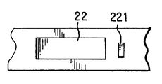
도13은 도14에 도시된 만입부 또는 노치(221)에 접합부를 고정하기 위해 돌기(251a)가 마련되고 횡단 절결부가 직선형이거나 어느 정도 곡선형일 수 있는 접합부(250)의 다른 실시예를 도시하고 있다.FIG. 13 shows another embodiment of a
위에서 언급된 바와 같이, 큰 체결력이 존재할 때 안내 후크의 후방 굽힘으로 인해 클램프가 재개방되는 문제를 제거하기 위해, 미국 특허 제4,299,012호(도4)는 하나 이상의 냉간-변형되어 딥-드로잉된 지지 후크(32)와 함께 종래의 안내 후크(31)를 사용하는 것을 제안하고 있으며, 이로 인해 안내 후크(31)와 외부 밴드부(11a)의 대응 개구(35)의 모서리 사이의 상호 작용은 밴드 중첩부(11a, 11b)가 클램프의 체결 중에 서로에 대해 당겨지도록 함으로써 그들 각각의 개구(35)에서의 지지 후크(32)의 결합을 개선한다. 비록 본 발명은 본 발명의 문제를 다르게 해결하고자 하는 것은 아니지만, 본 특허의 발명을 사용하는 상업상 유용한 클램프에서, 실제로 안내 후크(21)의 자유 단부는 재개방 위험을 감소 시키기 위해 순서대로 후방으로 구부러졌다(도5).As mentioned above, to eliminate the problem of reopening the clamp due to the rear bending of the guide hook in the presence of a large clamping force, U.S. Pat. It is proposed to use a
본 발명에 따른 접합면(51)의 제공은 안내 및 지지 후크의 조합을 이용하는 기계식 연결체의 유형에서 특히 유리한 데, 그 이유는 접합면(51)은 도15에 도시된 바와 같이 지지 후크(32)(들)가 대응 개구(35)(들)의 모서리 위로 연장되도록 하는 사전 조립 위치에서 접합면(51)과 결합하는 외부 밴드부(11a)가 미리 존재하도록 안내 후크(31) 상에 위치될 수 있어서, 상술한 미국 특허에서 제안된 바와 같이 체결이 수행될 때 밴드부를 서로 당기지 않고도 외부 밴드부와 지지 후크(32)(들)의 결합을 보장하기 때문이다. 즉, 접합면(51)은 임의의 체결력을 인가하기 시작할 때 이미 외부 밴드부(11a)가 지지 후크(32)와 신뢰성 있게 결합하기 위한 위치에 있도록 하는 위치에 두 개의 밴드부를 유지해서, 체결 작업 개시에서부터 모든 발생력을 미리 흡수하는 것을 돕는다. 따라서, 접합면(51)과 내부 밴드부(11b)의 외면 사이의 거리(X)는 클램핑 밴드의 두께보다 조금 커야만 하며 양호하게는 지지 후크(32)의 높이(Y)보다 작아야 한다.The provision of the joining
안내 후크는 일반적으로 폭과 길이가 작고 따라서 딥-드로잉에 의해 접합면을 제조함에 있어서 어려움이 있을 수 있기 때문에, 도16은 일반적으로 도면 부호 321로 표시된 안내 후크 자체가 직접 접합면(351)을 제공하는 개선된 양호한 실시예를 도시한다. 이것은 안내 후크(321)를 세 개의 구역(321a, 321b, 321c)을 제공하도록 두 번 구부림으로써 달성된다. 이로써 최내측 구역(321a)은 양호하게는 일반적인 경사 방향으로 외향 연장되고, 외부 밴드부의 평면에 적어도 거의 평행한 방향으로 연장된 구부러진 중심 구역(321b)에 인접하며, 중심 구역 다음에는 다시 양호하게는 내부 구역(321a)에 대체로 평행하고 가능하게는 도5를 참조해서 설명된 바와 같이 후방으로(도시 안됨) 구부러진 외부 구역(321c)이 이어진다. 접합면(351)을 형성하는 중심 구역(321b)은 대체로 직선형일 수 있거나, 사전 조립된 위치에서 클램핑 밴드의 곡률을 수용하기 위해 외부 밴드부의 외면과 공통 표면인 작은 곡률을 가질 수도 있다. 또한, 적절한 형상 강성을 제공하기 위해, 안내 후크(321)에는 안내 후크(321)의 적어도 두 굽힘부의 영역에서 연장되는 하나 이상의 만입부 또는 양각부(329a, 329b; 도17)가 제공될 수 있다. 그러나, 도17에 도시된 바와 같이, 강화 양각부 또는 만입부는 구역(321a)의 소정 부분으로부터 전체 구역(321b)을 넘어 구역(321c)의 부분까지 연장될 수도 있다. 단일 강화 만입부 또는 양각부가 도17에 도시되어 있지만, 각각의 그러한 만입부 또는 양각부가 연속적인 충분한 공간이 존재한다면 두 개의 이러한 만입부 또는 양각부가 나란히 마련될 수도 있다. 이들 양각부 또는 만입부는 안내 후크(321)의 양 측면 상에 제공될 수 있으며 구역(321a, 321b 및/또는 321c)의 서로 다른 측면들 상에 제공될 수도 있다. 도18은 블랭크가 계속 편평한 상태인 동안 양각부와 만입부들은 안내 후크 자체에 대한 U자 형상 절결부(321')와 동시에 또는 바로 전에도 제조될 수 있기 때문에 이와 같은 양각부 또는 만입부(329')를 간단히 제조하는 방법을 도시한다. Since the guide hooks are generally small in width and length and therefore may have difficulty in making the joint surface by deep-drawing, FIG. 16 generally indicates that the guide hook itself, indicated by
도21은 소위 결합된 안내 및 지지 후크가 일반적으로 도면 부호 431로 표시된 기계식 연결체에 적용되고 미국 특허 제4,622,720호에 개시된 본 발명의 다른 실시예를 도시한다. 이 특허의 종래 기술과 조합된 안내 및 지지 후크의 경사진 후방 안내면(431')은 직선형인 대신에 세 개의 구역 형상부(531a, 531b, 531c)를 구비하며(도21), 이들 구역 형상부들은 결합된 안내 및 지지 후크를 제조하기 위해 절결부의 형상을 변화시킴으로써, 즉 절결부의 형상을 평행 사변형으로부터 세 구역의 지그재그 형상으로 변화시킴으로써 용이하게 얻어질 수 있다. 따라서, 본 발명은 이와 같이 조합된 안내 및 지지 후크를 사용해서 특별히 간단한 방식으로 적용되고 실현될 수 있다.Figure 21 illustrates another embodiment of the invention in which a so-called combined guide and support hook is applied to a mechanical linkage, generally indicated at 431, and disclosed in US Pat. No. 4,622,720. The inclined rear guide surface 431 'of the guide and support hooks in combination with the prior art of this patent has three
따라서, 본 발명은 클램프의 재개방 위험이 더욱 최소화된다는 점과, 특히 도4 및 도15에 도시된 바와 같은 기계식 연결체를 가진 클램프를 사용함으로써, 지지 후크에 의한 체결력의 즉각적인 흡수가 본 발명에 의해 사전 조립 위치로부터 시작해서 항상 보장된다는 점에서 상당한 장점을 제공한다. 또한, 본 발명은 비용을 크게 증가시키지 않고도 간단한 제조 과정에 의해 실현될 수 있다.Accordingly, the present invention further minimizes the risk of reopening the clamp and, in particular, by using a clamp with a mechanical connection as shown in FIGS. This provides a significant advantage in that it is always guaranteed starting from the pre-assembly position. In addition, the present invention can be realized by a simple manufacturing process without significantly increasing the cost.
비록 본 출원인은 본 발명에 따른 여러 실시예만을 보여주고 설명하였으나, 본 발명은 이들 실시예에 제한되지 않으며 당해 기술 분야의 숙련자에게 공지된 바와 같은 다양한 변화 및 변형을 수용할 수 있음은 명백하다. 지적된 바와 같이, 본 발명은 체결이 시작되기 전에 결합되어야 하는 안내 후크를 포함하는 밴드 중첩부의 기계식 연결체와 체결 수단을 가진 개방 클램프에 특히 적용 가능하다. 물론, 본 발명은 체결 공구를 해제하기 전에 외부 밴드부를 내향으로 압박함으로서 안내 후크(131)와 지지 후크(132)가 그들 각각의 개구(135)에 결합될 때, 체결 작업의 최종 단계 중에 쉽게 재개방될 가능성을 감소시키기 위해 도6의 안내 후크(131)와 같은 안내 후크가 마련된 소위 이어리스 클램프에도 사용될 수 있다. 또한, 접합면(51, 151, 251, 351)에 대한 적절한 형상을 최적화하기 위해, 안내 후 크는 횡단면으로 약간 볼록하게 또는 오목하게 만곡될 수도 있다. 물론, 강화 만입부 또는 양각부는 전체 길이에 걸쳐 또는 안내 후크의 길이의 상당 부분에 걸쳐 연장될 수도 있다. 따라서, 본 출원인은 본 명세서에서 도시되고 설명된 것에 제한되기를 원하지 않으며, 첨부된 청구항의 범위에 의해 포함되는 모든 변화 및 변형을 포함하고자 한다.Although the Applicant has shown and described only various embodiments in accordance with the present invention, it is apparent that the present invention is not limited to these embodiments and can accommodate various changes and modifications as known to those skilled in the art. As pointed out, the invention is particularly applicable to mechanical clamps of the band overlap comprising guide guides which must be engaged before the fastening starts and an open clamp with fastening means. Of course, the present invention can be easily re-engaged during the final stage of the fastening operation when the guide hooks 131 and the support hooks 132 are engaged in their
Claims (25)
Applications Claiming Priority (4)
| Application Number | Priority Date | Filing Date | Title |
|---|---|---|---|
| US14291799P | 1999-07-09 | 1999-07-09 | |
| US60/142,917 | 1999-07-09 | ||
| US09/512,296 US6178601B1 (en) | 1999-07-09 | 2000-02-24 | Mechanical connection for open clamps |
| US09/512,296 | 2000-02-24 |
Publications (2)
| Publication Number | Publication Date |
|---|---|
| KR20020037741A KR20020037741A (en) | 2002-05-22 |
| KR100629297B1 true KR100629297B1 (en) | 2006-09-29 |
Family
ID=26840531
Family Applications (1)
| Application Number | Title | Priority Date | Filing Date |
|---|---|---|---|
| KR1020027000228A KR100629297B1 (en) | 1999-07-09 | 2000-07-07 | Mechanical connection for open clamps |
Country Status (13)
| Country | Link |
|---|---|
| US (1) | US6178601B1 (en) |
| EP (1) | EP1196712B1 (en) |
| JP (1) | JP2003504579A (en) |
| KR (1) | KR100629297B1 (en) |
| CN (1) | CN1144968C (en) |
| AT (1) | ATE470100T1 (en) |
| BR (1) | BR0011060B1 (en) |
| CA (1) | CA2371643C (en) |
| DE (1) | DE60044494D1 (en) |
| ES (1) | ES2343728T3 (en) |
| HK (1) | HK1045362B (en) |
| MX (1) | MXPA02000207A (en) |
| WO (1) | WO2001004533A1 (en) |
Families Citing this family (13)
| Publication number | Priority date | Publication date | Assignee | Title |
|---|---|---|---|---|
| DE60137547D1 (en) * | 2001-08-01 | 2009-03-12 | Stephen James Shaw | BACKREST SYSTEM AND TENSIONER FOR THIS |
| AU2003277658A1 (en) * | 2002-11-18 | 2004-06-15 | Kabushiki Kaisha Mihama | Tightening band |
| JP3950785B2 (en) | 2002-11-18 | 2007-08-01 | 株式会社ミハマ | Tightening band |
| CA2413675C (en) * | 2002-12-06 | 2010-07-13 | Wellmaster Pipe And Supply Inc. | Unitized corner brace |
| DE10259598A1 (en) * | 2002-12-19 | 2004-07-01 | Titan Umreifungstechnik Gmbh & Co Kg | Closure of a strap |
| US7549197B2 (en) * | 2003-12-01 | 2009-06-23 | Nhk Spring Co., Ltd. | Boot band |
| JP2006083918A (en) * | 2004-09-15 | 2006-03-30 | Suncall Corp | Clamp band |
| US7721393B2 (en) * | 2007-01-03 | 2010-05-25 | Craig Jr Paul M | Size-conscious hose clamp |
| US9624950B2 (en) | 2011-06-28 | 2017-04-18 | Nhk Spring Co., Ltd. | Boot band |
| USD741456S1 (en) * | 2013-07-17 | 2015-10-20 | Charlotte Pipe And Foundry Company | Crimp-style coupling device for clamping together cast iron pipes, fittings and the like |
| JP6220881B2 (en) * | 2013-09-25 | 2017-10-25 | ヘラマンタイトン株式会社 | Binding band fixing structure and binding tool |
| JP6212028B2 (en) * | 2014-12-26 | 2017-10-11 | トヨタ自動車株式会社 | Point friction stir welding structure |
| CN114161332A (en) * | 2020-09-10 | 2022-03-11 | 疆域康健创新医疗科技成都有限公司 | Assembly mechanism |
Family Cites Families (14)
| Publication number | Priority date | Publication date | Assignee | Title |
|---|---|---|---|---|
| US3321811A (en) * | 1965-03-31 | 1967-05-30 | Jurid Werke Gmbh | Metal clamping band |
| US4299012A (en) * | 1979-05-08 | 1981-11-10 | Hans Oetiker | Hose clamp |
| US4622720A (en) * | 1982-12-03 | 1986-11-18 | Hans Oetiker | Fastening arrangement for open hose clamp |
| US4492004A (en) * | 1982-12-03 | 1985-01-08 | Hans Oetiker | Earless clamp structure |
| US5230246A (en) * | 1984-06-20 | 1993-07-27 | Hans Oetiker Ag Maschinen- Und Apparatefabrik | Balancing arrangement for rotating member |
| CA1274068A (en) * | 1984-06-20 | 1990-09-18 | Hans Oetiker | Deformable ear for clamps |
| US4724583A (en) * | 1985-05-23 | 1988-02-16 | Nhk Spring Co., Ltd. | Hose band |
| JPS629011A (en) * | 1985-07-04 | 1987-01-17 | 日本発条株式会社 | Hose band |
| JPS62106111A (en) * | 1985-10-31 | 1987-05-16 | 日本発条株式会社 | Hose band |
| JPS62224709A (en) * | 1986-03-27 | 1987-10-02 | 日本発条株式会社 | Hose band |
| US4991266A (en) | 1986-12-17 | 1991-02-12 | Hans Oetiker Ag Maschinen- Und Apparatefabrik | Mechanical interlock for open clamp structures |
| US5274886A (en) * | 1986-12-17 | 1994-01-04 | Hans Oetiker Ag Maschinen- Und Apparatefabrik | Clamp structure with preassembly arrangement |
| JPH08232919A (en) * | 1995-02-24 | 1996-09-10 | Mihama Seisakusho:Kk | Tightening band |
| JPH08338410A (en) * | 1995-04-10 | 1996-12-24 | Toshiyuki Fukaya | Fastening band |
-
2000
- 2000-02-24 US US09/512,296 patent/US6178601B1/en not_active Expired - Fee Related
- 2000-07-07 DE DE60044494T patent/DE60044494D1/en not_active Expired - Lifetime
- 2000-07-07 CN CNB008092168A patent/CN1144968C/en not_active Expired - Fee Related
- 2000-07-07 AT AT00946790T patent/ATE470100T1/en not_active IP Right Cessation
- 2000-07-07 EP EP00946790A patent/EP1196712B1/en not_active Expired - Lifetime
- 2000-07-07 JP JP2001509907A patent/JP2003504579A/en active Pending
- 2000-07-07 ES ES00946790T patent/ES2343728T3/en not_active Expired - Lifetime
- 2000-07-07 WO PCT/US2000/016313 patent/WO2001004533A1/en active IP Right Grant
- 2000-07-07 MX MXPA02000207A patent/MXPA02000207A/en active IP Right Grant
- 2000-07-07 KR KR1020027000228A patent/KR100629297B1/en not_active IP Right Cessation
- 2000-07-07 CA CA2371643A patent/CA2371643C/en not_active Expired - Fee Related
- 2000-07-07 BR BRPI0011060-4A patent/BR0011060B1/en not_active IP Right Cessation
-
2002
- 2002-09-18 HK HK02106823.8A patent/HK1045362B/en not_active IP Right Cessation
Also Published As
| Publication number | Publication date |
|---|---|
| BR0011060B1 (en) | 2009-01-13 |
| CA2371643C (en) | 2010-12-21 |
| CN1357088A (en) | 2002-07-03 |
| ES2343728T3 (en) | 2010-08-09 |
| ATE470100T1 (en) | 2010-06-15 |
| US6178601B1 (en) | 2001-01-30 |
| EP1196712A4 (en) | 2007-06-13 |
| HK1045362B (en) | 2010-09-03 |
| BR0011060A (en) | 2002-03-05 |
| EP1196712A1 (en) | 2002-04-17 |
| JP2003504579A (en) | 2003-02-04 |
| WO2001004533A1 (en) | 2001-01-18 |
| EP1196712B1 (en) | 2010-06-02 |
| MXPA02000207A (en) | 2002-08-12 |
| CN1144968C (en) | 2004-04-07 |
| HK1045362A1 (en) | 2002-11-22 |
| KR20020037741A (en) | 2002-05-22 |
| DE60044494D1 (en) | 2010-07-15 |
| CA2371643A1 (en) | 2001-01-18 |
Similar Documents
| Publication | Publication Date | Title |
|---|---|---|
| KR100629297B1 (en) | Mechanical connection for open clamps | |
| EP0697554B2 (en) | Tolerance-compensating hose clamp | |
| GB2160578A (en) | Clamp structure e g for hose | |
| KR100796432B1 (en) | Hose clamps with clamping surfaces devoid of gaps | |
| JPS6113091A (en) | Clamping device for opening type hose clamp | |
| US8286308B2 (en) | Band clamp | |
| JP4060907B2 (en) | Improved low collar clamp | |
| US5138747A (en) | Clamp structure with improved spring action | |
| EP0730116B1 (en) | Clamp structure with spring element | |
| US4711001A (en) | Fastening arrangement for open hose clamp | |
| KR100625140B1 (en) | Improved tightening means for hose clamps | |
| MXPA04011158A (en) | Hose clamp with internal clamping surfaces devoid of gaps, steps or discontinuities. | |
| EP2109731B1 (en) | Mechanical connection for open-type hose clamps | |
| JP3359113B2 (en) | Tightening band and tightening tool | |
| JPH0914550A (en) | Fastening band |
Legal Events
| Date | Code | Title | Description |
|---|---|---|---|
| A201 | Request for examination | ||
| E701 | Decision to grant or registration of patent right | ||
| GRNT | Written decision to grant | ||
| FPAY | Annual fee payment |
Payment date: 20100719 Year of fee payment: 5 |
|
| LAPS | Lapse due to unpaid annual fee |