KR100600250B1 - Seat belt retractor having a torsion bar - Google Patents
Seat belt retractor having a torsion bar Download PDFInfo
- Publication number
- KR100600250B1 KR100600250B1 KR1020017004516A KR20017004516A KR100600250B1 KR 100600250 B1 KR100600250 B1 KR 100600250B1 KR 1020017004516 A KR1020017004516 A KR 1020017004516A KR 20017004516 A KR20017004516 A KR 20017004516A KR 100600250 B1 KR100600250 B1 KR 100600250B1
- Authority
- KR
- South Korea
- Prior art keywords
- torsion bar
- seat belt
- spool
- bar
- delete delete
- Prior art date
Links
Images
Classifications
-
- B—PERFORMING OPERATIONS; TRANSPORTING
- B60—VEHICLES IN GENERAL
- B60R—VEHICLES, VEHICLE FITTINGS, OR VEHICLE PARTS, NOT OTHERWISE PROVIDED FOR
- B60R22/00—Safety belts or body harnesses in vehicles
- B60R22/34—Belt retractors, e.g. reels
-
- B—PERFORMING OPERATIONS; TRANSPORTING
- B60—VEHICLES IN GENERAL
- B60R—VEHICLES, VEHICLE FITTINGS, OR VEHICLE PARTS, NOT OTHERWISE PROVIDED FOR
- B60R22/00—Safety belts or body harnesses in vehicles
- B60R22/34—Belt retractors, e.g. reels
- B60R22/341—Belt retractors, e.g. reels comprising energy-absorbing means
- B60R22/3413—Belt retractors, e.g. reels comprising energy-absorbing means operating between belt reel and retractor frame
-
- B—PERFORMING OPERATIONS; TRANSPORTING
- B60—VEHICLES IN GENERAL
- B60R—VEHICLES, VEHICLE FITTINGS, OR VEHICLE PARTS, NOT OTHERWISE PROVIDED FOR
- B60R22/00—Safety belts or body harnesses in vehicles
- B60R22/28—Safety belts or body harnesses in vehicles incorporating energy-absorbing devices
- B60R2022/286—Safety belts or body harnesses in vehicles incorporating energy-absorbing devices using deformation of material
- B60R2022/287—Safety belts or body harnesses in vehicles incorporating energy-absorbing devices using deformation of material of torsion rods or tubes
Landscapes
- Engineering & Computer Science (AREA)
- Mechanical Engineering (AREA)
- Automotive Seat Belt Assembly (AREA)
- Springs (AREA)
Abstract
Description
본 발명은 일반적으로 토션 바아(torsion bar)를 구비한 좌석 벨트 수축기에 관한 것이다.FIELD OF THE INVENTION The present invention generally relates to seat belt retractors having a torsion bar.
종래의 좌석 벨트 수축기는 프레임을 포함하며 스풀(spool)이 프레임에 회전되게 장착된다. 스풀은 전형적으로 하나 또는 그 이상의 로크 휠을 구비하며 각각의 로크 휠은 상응하는 로크 폴(lock pawl)에 의해 결합되고 로킹되는 다수의 톱니를 갖는다. 로크 폴 또는 로크 도그(dog)는 프레임에 회전되게 장착되며 로크 휠의 톱니에 대해 해체 위치로부터 결합 위치까지 이동 가능하다. 이러한 형식의 수축기에 있어서 일단 스풀이 로킹되면, 스풀의 추가 회전이 불가능해진다. 당업자라면 자동차 탑승자가 로킹된 수축기에 하중을 가함에 따라, 좌석 벨트가 응력을 받고 늘어나 좌석 벨트가 미끄러지기 때문에(소위 필름 스풀 효과) 이러한 형식의 수축기에서는 자동차 탑승자의 모든 전방 이동이 정지되지 않음을 인식할 것이다.A conventional seat belt retractor includes a frame and a spool is mounted to rotate on the frame. Spools typically have one or more lock wheels and each lock wheel has a number of teeth that are engaged and locked by corresponding lock pawls. The lock pawl or lock dog is rotatably mounted to the frame and is movable from the disengaged position to the engaged position relative to the teeth of the lock wheel. In this type of shrinkage, once the spool is locked, further rotation of the spool is impossible. Those skilled in the art will appreciate that as the occupant loads the locked systolic, the seat belt will be stressed and stretched, causing the seat belt to slip (so-called film spool effect), so that all forward movement of the occupant of the car will not stop in this type of systolic. Will recognize.
그러나, 에너지 흡수형 수축기에서는, 스풀과 그와 연관된 기구가 회전하게 되고 자동차 탑승자에 의해 좌석 벨트에 인가된 하중에 응하여 좌석 벨트가 제어 가능하게 신장(protraction)되게 된다. 자동차 탑승자의 전방 운동은 수축기내에 발생된 반작용력 또는 토크에 의해 억제되고 당겨진 좌석 벨트에 의해 조절된다. 이러한 방식으로 좌석 벨트의 신장과 자동차 탑승자의 전방 운동이 제어된다. 에너지 흡수형 좌석 벨트 수축기는 대체로 분쇄 부싱(crushable bushing) 또는 토션 바아와 같은 변형 가능한 부재를 사용한다. 어느 경우든지, 운동하는 자동차 탑승자에 의해 좌석 벨트에 전해진 힘을 통하여 수축기 스풀에 전달된 토크에 대해 작용하는 소정의 반작용 토크(이론적으로는 일정함)를 발생시키기 위해 그 탄성 한계를 지나 소성 범위 또는 영역으로 진입하여 부싱은 분쇄되거나 토션 바아는 비틀린다.However, in an energy absorbing systolic machine, the spool and its associated mechanisms rotate and cause the seat belt to be controllable in response to a load applied to the seat belt by the vehicle occupant. The forward movement of the vehicle occupant is controlled by the seat belt pulled down and suppressed by the reaction forces or torques generated in the systolic. In this way the extension of the seat belt and the forward movement of the vehicle occupant are controlled. Energy absorbing seat belt shrinkers generally employ deformable members such as crushable bushings or torsion bars. In either case, the plastic range beyond its elastic limit to generate a predetermined reaction torque (which is theoretically constant) acting on the torque transmitted to the systolic spool via the force transmitted to the seat belt by the motor vehicle occupant, or Entering the zone the bushing is crushed or the torsion bar is twisted.
에너지 흡수형 수축기의 목적은 자동차 탑승자의 전방 운동에 반대되는 대체로 일정한 반작용력을 발생시키고 충돌 도중, 즉 좌석 벨트가 자동차 탑승자에 의해 하중을 받는 전체 시간 동안 이러한 반작용력을 발생시키는 것이다. 이론적으로 이것은 항상 일정한 소성 영역에서 작동하는 분쇄 부싱 또는 토션 바아를 사용함으로써 달성된다.The purpose of the energy absorbing systolic is to generate a generally constant reaction force as opposed to the forward movement of the vehicle occupant and to generate this reaction force during the collision, i.e. the entire time the seat belt is loaded by the vehicle occupant. In theory this is achieved by using grinding bushings or torsion bars that always operate in a constant firing area.
좌석 벨트 수축기의 토션 바아에 있어서, 토션 바아의 한쪽 단부는 로크 휠에 단단히 부착되고 다른 쪽 단부는 수축기 스풀에 고정된다. 충돌 도중 로크 도그 또는 로크 폴을 로크 휠의 톱니에 개재시킴으로써 로크 휠이 회전하는 것이 방지된다. 좌석 벨트가 자동차 탑승자에 의해 하중을 받으면, 토션 바아가 비틀어짐에 따라, 스풀은 토션 바아내에 발생된 반작용 토크에 반대되게 회전하는 경향이 있다. 발생된 반작용 토크는 토션 바아의 물리적 특성뿐만 아니라 토션 바아가 회전되고 비틀어진 양에 따른다.In the torsion bar of the seat belt retractor, one end of the torsion bar is firmly attached to the lock wheel and the other end is secured to the retractor spool. The locking of the lock wheel is prevented by interposing the lock dog or the lock pawl in the teeth of the lock wheel during the collision. As the seat belt is loaded by the vehicle occupant, as the torsion bar is twisted, the spool tends to rotate against the reaction torque generated in the torsion bar. The generated reaction torque depends not only on the physical properties of the torsion bar but also on the amount the torsion bar is rotated and twisted.
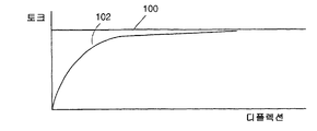
보다 상세하게는, 토션 바아에 의해 발생된 반작용 토크는 토션 바아가 탄성, 전이 또는 소성 영역 또는 범위에 있는 가에 따라 변할 것이다. 언급된 바와 같이, 이상적인 토션 바아에서는, 탄성 범위는 급경사(바람직하게는 무한한 급경사 또는 디플렉션 곡선)를 특징으로 하며, 소성 범위는 탄성 영역으로부터 급격한 전이를 갖는 완벽하게 일정한 토크 디플렉션 영역을 특징으로 한다. 이러한 이상적인 토션 바아 및 해당 좌석 벨트 수축기에 있어서, 일단 토션 바아의 제 1 단부가 로킹되고 스풀이 하중을 받으면, 토션 바아는 즉각 그 탄성 범위로부터 작동의 소성 범위로[도 1의 곡선(100) 참조] 전이되고 좌석 벨트가 신장됨에 따라 일정한 반작용력이 수축기에 의해 발생되게 된다.More specifically, the reaction torque generated by the torsion bar will vary depending on whether the torsion bar is in an elastic, transitional or plastic zone or range. As mentioned, in an ideal torsion bar, the elastic range is characterized by steep slopes (preferably infinite steep slopes or deflection curves), and the plastic range is characterized by perfectly constant torque deflection regions with a sharp transition from the elastic region. do. In this ideal torsion bar and corresponding seat belt retractor, once the first end of the torsion bar is locked and the spool is loaded, the torsion bar immediately moves from its elastic range to the plastic range of operation (see
종래 기술의 토션 바아는 다수의 상이한 제조 방법을 사용하여 제조되었다. 일 방법에서는, 과도한 크기의 금속 바아가 가공되어 그 직경을 소망 치수로 감소시킨다. 그 뒤, 단부 형성부가 냉간 압연과 같은 방식에 의해 가공된 바아상에 형성된다. 바아를 가공함으로써 전형적으로 불균일한 응력 상승부(riser)가 발생될 수 있으며 가공된 바아를 냉간 압연함으로써 금속의 입자 구조가 바람직하지 않은 방식으로 재배향된다. 토션 바아내의 응력 분포를 보다 균일하게 하기 위해, 풀림(annealing) 단계가 종종 사용되지만, 이는 최종 제품의 가격을 상승시킨다. 그러나, 이러한 형식의 토션 바아가 탄성 영역, 연장된 탄성/소성 전이 영역 및 소성 영역을 갖는 도 1의 곡선(102)에 도시된 것과 유사한 특성 토크 디플렉션 곡선(torque deflection curve)을 나타내므로 본 발명의 목적을 달성하지는 못한다. 다른 제조 방법에서는 금속 바아 또는 와이어(직경이 큼)가 소망 치수보다 작은 직경을 갖게 되는 냉간-성형 공정을 사용하여 토션 바아가 제조된다. 소망 직경보다 작은 바아는 소망의 보다 큰 직경을 갖는 바아로 팽창된다. 이러한 형식의 바아가 시험되었으며 도 1의 곡선(102)과 유사한 특성 토크 디플렉션 곡선을 나타낸다. 종래 기술은 또한 짧아지거나 급격한 탄성/소성 전이 영역을 갖는 토션 바아를 제조하는 방법을 제안했다. 이러한 방법에서는 사전가공되거나 사전성형된 토션 바아는 좌석 벨트 수축기내에 설치되기 전에 가공 경화(그 항복 토크 레벨을 넘어 사전 토크가 가해지거나 비틀어짐으로써)된다. 이러한 기술의 하나의 잠재적 결함은 일단 수축기내에 설치되면 사전 비틀림(pre-twisting)이 토션 바아가 충돌 도중 추가적으로 비틀어질 수 있는 유용한 범위를 감소시킨다는 것이다.Prior art torsion bars have been produced using a number of different manufacturing methods. In one method, oversized metal bars are processed to reduce their diameter to the desired dimensions. Thereafter, the end forming portion is formed on the processed bar by a method such as cold rolling. By processing the bar typically a non-uniform stress riser can be generated and by cold rolling the processed bar the grain structure of the metal is redirected in an undesirable manner. In order to make the stress distribution in the torsion bar more uniform, an annealing step is often used, but this raises the price of the final product. However, this type of torsion bar exhibits a characteristic torque deflection curve similar to that shown in
좌석 벨트 수축기내에 사용되는 토션 바아를 제작하는 다른 방법론이 종래에 제안되었다. 토션 바아는 단부 형성부 사이에 위치된 연성의 기다란 본체로 성형되고 과도한 크기의 금속 바아를 감소된 직경의 바아로 압출시킴으로써 초기 응력이 가해진 바아 스톡으로서 형성되었으며, 바아의 중심 부근의 입자 구조는 종방향으로 배향되었다. 토션 바아의 단부 형성부는 냉간 헤딩 공정(cold heading process)에 의해 성형되었다. 이러한 공정에서는 냉간 헤딩된 바아는 풀림되지 않았다. 이러한 공정에서는, 냉간 헤딩은 토션 바아의 중앙 부분내의 종방향 입자 구조를 교란하지 않았다.Other methodologies for manufacturing torsion bars for use in seat belt retractors have been proposed in the past. The torsion bar was formed as a bar stock that was initially stressed by extruding an oversized metal bar into a reduced diameter bar formed into a soft elongated body located between the end formations, and the grain structure near the center of the bar Direction is oriented. The end formations of the torsion bar were molded by a cold heading process. In this process, the cold headed bar did not loosen. In this process, cold heading did not disturb the longitudinal particle structure in the central portion of the torsion bar.
제안된 바와 같이 냉간 헤딩 형성부를 갖는 바아 스톡이 먼저 압출되고 그 후 토션 바아가 입자 구조를 증가시키지 않을 온도 또는 기간에서 풀림되고 토션 바아가 사전 비틀림 된다면, 우수한 결과가 기대될 수 있음이 발견되었다.It has been found that good results can be expected if the bar stock with cold heading formation as proposed is first extruded and then unwound at a temperature or period of time where the torsion bar will not increase the grain structure and the torsion bar is pre-twisted.
도 1은 원형 단면을 갖는 이상적인 토션 바아와 종래의 토션 바아에 대한 토크 디플렉션 곡선을 도시하는 도면,1 shows a torque deflection curve for an ideal torsion bar with a circular cross section and a conventional torsion bar;
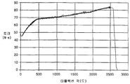
도 2는 냉간 성형되고 풀림된 토션 바아에 대한 토크 디플렉션 곡선을 도시하는 시험 데이터를 도시하는 도면,FIG. 2 shows test data showing a torque deflection curve for a cold formed and loosened torsion bar; FIG.
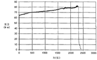
도 2a는 냉간 성형, 풀림 및 사전 비틀림된 토션 바아에 대한 시험 데이터를 도시하는 도면,2A shows test data for cold forming, unwinding and pre-twisted torsion bars, FIG.
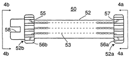
도 3a 및 도 3b는 다양한 완성 단계의 토션 바아를 도시하는 도면,3a and 3b show torsion bars of various completion stages,
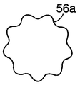
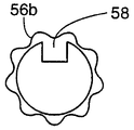
도 4a 및 도 4b는 토션 바아의 단부 평면도,4A and 4B are end plan views of the torsion bar,
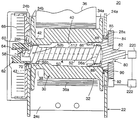
도 5는 본 발명의 토션 바아가 합체된 좌석 벨트 수축기를 도시하는 도면,5 shows a seat belt retractor incorporating a torsion bar of the present invention;
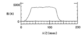
도 6은 벨트 힘 대 시간의 곡선을 도시하는 도면.6 shows a curve of belt force versus time.
도 3a 및 도 3b는 본 발명에 따라 제조된 토션 바아를 도시한다. 토션 바아(50)는 중심체(52)와 토션 바아를 각각 스프링 아버(arbor) 및 래칫체(ratchet body)와 맞물리게 하는 두 개의 단부 형성부(52a, 52b)를 구비한다. 토션 바아(50)는 원형 직경을 갖는 금속의 바아(또는 큰 직경의 와이어)로 제조된다. 실시예에 있어서 바아 또는 와이어는 AIAI/SAE 1005 변형(CHQ) 등급의 와이어 또는 스톡으로부터 제조된다. 와이어 또는 스톡은 50 내지 70, 그리고 바람직하게는 60 내지 65의 범위의 로크웰(Rockwell) B 등급을 갖는 공지된 열간 압연 알루미늄 킬드 세립 구상 풀림 강(aluminum killed fine grain spheridized annealed steel)을 사용하여 성형된다. 이러한 금속은 최대 0.1mm의 시임 깊이(seam depth)의 표면 다듬기(surface finish)를 갖는다. 인장 강도는 2,812 내지 4,218㎏/㎠ 사이에 있어야 한다. 바아 스톡의 최적 화학 성분은, 탄소 0.06, 망간 0.35, 인 0.02, 황 0.02, 실리콘 0.1, 구리 0.01, 크롬 0.08, 몰리브덴 0.04 및 알루미늄 0.06인 것이 바람직하다. 신장률은 5㎝에서 25%이다. 바아 스톡의 직경은 9.525 와 11.099mm 사이에 있다. 이러한 금속의 입자 구조가 일반적으로 종으로 배향되어 충분한 연성을 가지므로 이러한 금속이 선택된다.3A and 3B show torsion bars made in accordance with the present invention. The
금속 바아(110)의 최초 직경(Di)(도 3a에 도시됨)은 대략 토션 바아(50)의 최종 직경(Df)보다 대략 5%가 크다. 토션 바아의 최종 직경은 약 1cm(9.8mm)이다. 토션 바아의 최종 직경은 바아(110)(도 3a에 도시됨)가 부분적으로 다이(도시되지 않음)를 통해 가압되고 그 후 바아(110)가 소망의 길이로 절단되는 냉간 성형 압출 공정을 사용하여 달성된다. 이러한 압출 공정 또는 단계 도중, 금속 바아(110)의 입자 구조는 일반적으로 종방향으로 배향된 상태로 유지된다. 참조부호(53)는 종방향 입자 구조의 전형적 패턴을 개략적으로 도시한다. 즉, 입자 구조는 토션 바아(50)의 축(112)에 실질적으로 평행하게 배향된다. 원래의 바아 또는 와이어 스톡의 입자 구조가 종방향으로 배향된 입자 구조를 갖지 않더라도 이러한 압출 공정이 입자 구조를 그와 같이 배향시킬 것이다.The initial diameter Di of the metal bar 110 (shown in FIG. 3A) is approximately 5% greater than the final diameter Df of the
바아(110)의 직경을 소망의 치수로 감소시킨 후, 바아의 단부는 단부 형성부(52a, 52b)를 형성하도록 냉간 헤딩된다. 이러한 형성부는 여러 단계의 공정 또는 단일 단계의 공정으로 성형될 수 있다. 도 4a 및 도 4b는 단부 형성부의 각각의 단부도이다. 단부 형성부(52a)는 다수의 스플라인(56a)이 형성된 확대된 직경 섹션을 구비한다. 단부 형성부(52b)는 스플라인(56b)과 도 5에 도시된 바와 같은 스프링 아버(60)를 수용하는 수단을 제공하는 일체로 형성된 노치 또는 홈(58)이 있는 확대된 섹션을 구비한다. 확대된 직경의 스플라인(56a, 56b)된 섹션을 형성하기 위해 사용된 냉간 헤딩 공정이 재료의 입자 구조에 반경방향의 요소를 추가할 뿐만 아니라 바아내에 종방향의 입자 구조를 유지할 것이다. 그러나, 전이 반경(55, 57)(도 3b에 도시됨)에 의해 입자 구조 및 응력 분포내의 어떠한 불연속성도 방지되는 것으로 생각된다. 그 후, 상기 형성된 토션 바아는 바아의 입자 크기를 교란하지 않는 온도와 기간에서 풀림된다. 불행하게도, 풀림된 토션 바아는 소망의 정밀한 토크 디플렉션 곡선을 제공하지 않는다. 그 특징으로서, 이러한 곡선(도 2의 시험 데이터 참조)은 낮은 항복점을 나타낸다. 이러한 낮은 항복점으로 인해 실제 사용시 발생될 수 있는 결과는 풀림된 토션 바아가 조기에 항복될 수도 있다는 것이다.After reducing the diameter of
토션 바아를 풀림한 후 다시 사전 비틀림에 의해 예비 응력이 가해진다. 상기 설명된 바아 재료(직경 9.8mm 토션 바아의 원형 바아로 성형됨)와 58.3mm의 전체 길이(단부 형성부의 팁 사이의 거리)에 대하여 바아는 0.5 회전(즉, 180°)만큼 비틀어진다. 그에 따른 시험 데이터가 도 2a에 도시되어 있다. 도시된 바와 같이 도 2에 도시된 낮은 항복점은 배제되었다. 바아에 의해 그 소성 영역내에 발생된 토크는 1도(degree)당 약 0.0067Nm의 기울기로 다소 직선적으로 증가한다. 이러한 토션 바아의 차후의 시험에 의해 낮은 항복점을 제거하는 효과가 충돌시 운동학적 성능을 향상시키는 것으로 확인되었다. 토션 바아(70)의 탄성과 소성 거동 사이의 급격히 감소된 전이 영역을 도시하고 상기 설명된 바와 같은 사전 비틀림으로 달성된 도 2a의 시험 데이터를 다시 참조한다. 사전 비틀림 양은 바아의 직경, 길이 및 재료의 선택에 따라 가장 바람직하게 변할 것이다.After the torsion bar is loosened, the prestress is again prestressed. The bar is twisted by 0.5 revolutions (ie 180 °) for the bar material described above (formed as a circular bar of 9.8 mm diameter torsion bar) and a total length of 58.3 mm (distance between the tip of the end forming part). Test data accordingly is shown in FIG. 2A. As shown, the low yield point shown in FIG. 2 is excluded. The torque generated by the bar in its firing region increases somewhat linearly with a slope of about 0.0067 Nm per degree. Subsequent tests of these torsion bars have shown that the effect of eliminating low yield points improves kinematic performance in collisions. Reference is again made to the test data of FIG. 2A, which shows a sharply reduced transition area between the elasticity and plastic behavior of the
에너지 흡수형 좌석 벨트 수축기(20)와 토션 바아의 주된 구성요소의 구성을 일반적으로 도시하는 도 5를 참조한다. 수축기(20)는 제 1 및 제 2 측면(24a, 24b)과 후방 측면(24c)이 있는 프레임(22)을 포함하며, 제 1 및 제 2 측면은 제 1 개구(28a 또는 28b)를 구비한다. 수축기(20)는 또한 프레임상에 회전되게 지지된 중공의 스풀(30)을 구비한다. 스풀(30)은 중심체(32)와 중심체의 각각의 단부에서 마주보는 플랜지(34a, 34b)를 구비한다. 중심체는 중공의 보어(40)를 구비하며 보어는 그 일 단부에 형성된 스플라인(42)을 갖는다. 중심체는 또한 한 벌의 좌석 벨트(좌석 벨트 웨빙)(36)의 단부를 수용하고 고정하기 위해 공지된 구성의 슬롯(도시되지 않음)과 같은 수단을 구비한다. 참조부호(36a)는 스풀 주위로 권취된 좌석 벨트(36)의 몇 개의 층을 지시한다.Reference is made to FIG. 5, which generally shows the configuration of the energy absorbing
토션 바아(50)는 보어(40)내에 수용된다. 토션 바아는 중심체(52)와 단부 형성부(52a, 52b)를 구비한다. 언급된 바와 같이, 단부 형성부(52b)는 스플라인(56b)[스풀의 스플라인(42)과 구동적으로 결합함]을 구비한다. 노치 또는 홈(58)(도 4b에 도시됨)이 스프링 아버(62)의 구동 키(60)를 수용한다. 스프링 아버는 재권취 스프링(rewind spring)(66)의 내측 단부가 수용되는 슬롯(64)을 구비한다. 재권취 스프링(66)의 외측 단부는 스프링 덮개(68)에 고정된다. 덮개는 프레임 측면(24b)에 고정되며 프레임 개구(28b)내에 수용된 원형 돌출부(70)를 구비한다. 원형 돌출부는 스프링 아버(62), 토션 바아(50) 및 스풀(30)을 회전되게 지지하는 부싱으로서 작용한다. 스풀은 토션 바아(50)의 스플라인(42)의 부근에 위치된 마주보는 포켓(38)을 구비한다. 토션 바아가 정위치에 위치된 상태에서, 공구가 포켓내로 삽입되어 스풀 스플라인(42)과 토션 바아 스플라인(56b)을 함께 크림프(crimp)하도록 스풀(30)을 국부적으로 변형시킨다.
비상 잠금 수축기(emergency locking retractor; ELR)는 다양한 래칫 또는 로크 휠 조립체를 구비한다. 본 발명에 사용되는 정밀한 형태가 특별히 중요하지는 않다. 당해 분야에 공지된 바와 같이, 래칫 휠 조립체는 좌석 벨트의 신장을 중지시키기 위해 로크 폴이 래칫 또는 로크 휠상의 톱니와 결합되게 하는 센서 수단을 구비한다. 그러한 수단에는 전형적으로 소정 레벨을 넘어선 자동차 감속을 감지하는 차량 또는 관성 센서와 좌석 벨트(웨빙)가 측정 가능한 레벨을 초과한 속도로 스풀로부터 당겨질 때 수축기의 로킹을 개시하도록 작동되는 웹 센서가 사용된다. 수축기 또는 로크 휠 조립체는 플라스틱 또는 금속의 래칫 휠과 결합하는 하나 또는 그 이상의 플라스틱 센서 폴(pawl)을 사용할 수도 있으며, 이 플라스틱 또는 금속 래칫 휠은 수축기 샤프트(본 발명의 경우 토션 바아)에 로크 컵(lock cup)을 결합시킨다. 로크 컵을 샤프트(토션 바아)에 결합함으로써 로크 컵이 회전한다. 로크 컵이 운동함으로써 전형적으로 금속인 하중 흡수 로크 폴이 하중 흡수 금속 로크 휠과 결합하게 되고, 따라서 일시적이지만(토션 바아와 같은 에너지 흡수용 구성요소를 사용할 때), 좌석 벨트의 신장이 중지된다. 본 발명에 사용될 수 있는 그러한 로크 휠 조립체가 미국 특허 제 5,529,258 호 또는 유럽 특허 제 0 228 729 호에 개시되며 그 내용이 본 명세서에 참조로 인용된다.The emergency locking retractor (ELR) has various ratchet or lock wheel assemblies. The precise form used in the present invention is not particularly important. As is known in the art, the ratchet wheel assembly has sensor means to allow the lock pawl to engage the teeth on the ratchet or the lock wheel to stop the extension of the seat belt. Such means typically use a vehicle or inertial sensor that detects vehicle deceleration above a certain level and a web sensor that is activated to initiate locking of the systolic when the seat belt (webbing) is pulled from the spool at a speed above a measurable level. . The systolic or lock wheel assembly may use one or more plastic sensor pawls that engage the plastic or metal ratchet wheels, which plastic or metal ratchet wheels may have a lock cup on the systolic shaft (torsion bar in the present invention). (lock cup) is combined. The lock cup rotates by engaging the lock cup to the shaft (torsion bar). The movement of the lock cup causes the load absorbing lock pawl, which is typically metal, to engage with the load absorbing metal lock wheel and thus is temporary (when using an energy absorbing component such as a torsion bar), but the extension of the seat belt stops. Such lock wheel assemblies that can be used in the present invention are disclosed in US Pat. No. 5,529,258 or
토션 바아(50)의 단부 형성부(52a)는 래칫 휠 조립체(80)에 고정된다. 조립체는 래칫체(82)와 톱니(85)를 갖는 로크 휠 조립체(또는 래칫 휠 조립체)(84)를 구비한다. 래칫체는 토션 바아(50)의 스플라인(56a)과 결합하는 내부 스플라인(88)을 갖는 관형 부분(86)을 구비한다. 로크 휠은 래칫체(82)의 일부분일 수도 있거나 도시된 바와 같이 래칫체에 끼워진 별개의 부분일 수도 있다. 래칫체는 프레임 개구(28a)내에 수용되며 부싱(90)에 의해 지지된다. 로크 폴(92)은 프레임 측면(24a)상에 회전되게 지지되며 자동차 또는 웹 센서의 작동에 응하여 로크 휠 조립체(84)의 톱니(85)와 결합되게 이동 가능하다.
로크 휠 조립체(80)는 스풀(30) 회전의 각가속도를 감지하기 위해 결합된 웹 센서(220)를 구비한다. 도시된 바와 같이, 웹 센서는 로크 휠 조립체를 통하여 토션 바아(50)에 결합되며, 로크 휠 조립체의 속도(잠금 전)는 스풀의 속도이다. 로크 휠 조립체는 차량 센서(222)를 더 구비한다. 상기 언급된 바와 같이, 웹 및 차량 센서의 특정한 수행은 다양할 것이나, 이는 당해 분야에 공지되어 있다. 차량 또는 웹 센서중 어느 하나가 작동될 때마다, 로크 폴(92)은 공지된 기구를 통해 로크 휠 조립체(84)와 잠금 결합되게 된다.The
수축기(20)의 작동은 상기 개괄된 것과 대체로 동일하다. 충돌 도중, 토션 바아(50)의 단부 형성부(52a)는 더 회전하지 않게 로킹되며 자동차 탑승자가 전방으로 이동하거나 또는 이동하려고 함에 따라 좌석 벨트는 하중을 받게 된다. 자동차 탑승자의 하중이 벨트(36)를 통하여 스풀(30)에 전달되며, 토션 바아의 스프링 단부 형성부(52b)가 회전함에 따라 발생된 반발 토크에 의해 그 이동이 방해된다. 증가된 자동차 탑승자의 하중이 스풀(30)과 토션 바아를 반발력에 반대되게 회전하도록 하며, 그에 의해 좌석 벨트(36)를 신장시키고 자동차 탑승자를 제어된 방식으로 전방으로 이동하게 한다.The operation of the systolic 20 is largely the same as that outlined above. During the collision, the
종래 기술에서는 일정한 힘의 수축기로서 에너지 흡수형 좌석 벨트 수축기를 참조했다. 이러한 참조는 토션 바아 또는 분쇄 링과 같은 에너지 흡수 장치가 그 소성 영역내로 변형될 때 달성되는 이론적으로 일정한 소성 반발 토크(또는 반발력)로 추정된다. 예컨대 토션 바아에서 이러한 일정한 토크를 발생시킴으로써, 이러한 힘이 수축기 스풀에 또한 그 후 좌석 벨트에 전달된다. 그러나, 일반적으로 일정한 반발력을 나타내는 수축기를 생산하는 것이 목적이라면, 완전한 토션 바아를 사용할 지라도 이는 달성되지 않을 것이다. 이는 하기에서 알 수 있다. 좌석 벨트상의 반발력 F는 정상 상태에서 F = 0.5 ×D ×T이며, F는 벨트에서 측정된 반발력이고, D는 스풀의 유효 직경에 그 상에 웨빙된 좌석 벨트의 임의의 롤을 더한 것이며 T는 토션 바아에 의해 발생된 반발 토크이다. 자동차 탑승자가 스풀에 하중을 가함에 따라, 토션 바아는 비틀어지기 시작하고 반발 토크를 발생한다. 그러나, 스풀이 비틀어짐에 따라, 보다 많은 좌석 벨트 웨빙이 스풀로부터 신장되고 유효 직경 D는 감소한다. 따라서, 토크 T가 일정할 지라도, 벨트 반발력은 스풀로부터 제거된 벨트와 상응하게 변할 수 있다.In the prior art, energy-absorbing seat belt shrinkers have been referred to as contractors of constant force. This reference is presumed to be the theoretically constant plastic rebound torque (or repulsive force) achieved when an energy absorbing device, such as a torsion bar or grinding ring, is deformed into its plastic zone. By generating this constant torque, for example at the torsion bar, this force is transmitted to the systolic spool and then to the seat belt. However, if the goal is to produce a systolic that generally exhibits a constant repulsive force, this will not be achieved even with a complete torsion bar. This can be seen below. Repulsive force F on the seat belt is F = 0.5 × D × T at steady state, F is the repulsive force measured on the belt, D is the effective diameter of the spool plus any roll of seat belt webbing on it Rebound torque generated by the torsion bar. As the vehicle occupant loads the spool, the torsion bar begins to twist and generates rebound torque. However, as the spool twists, more seat belt webbing extends from the spool and the effective diameter D decreases. Thus, even if the torque T is constant, the belt repulsive force can vary corresponding to the belt removed from the spool.
도 6은 95백분위수(95th percentile) 하이브리드 Ⅲ 모형과 상기 설명된 토션 바아 수축기를 사용한 충돌 시뮬레이션에 대한 시험 데이터이다. 이 시험 데이터는 본 발명에서 사용된 수축기가 현저하게 일정한 반발력을 발생할 수 있음을 도시한다. 이 시험 전에 좌석 벨트 웨빙은 수축기로부터 당겨져서 모형에 고정되었으며 좌석 벨트의 약 3 내지 4개의 층이 스풀상에 감겨진 채로 남게된다. 시험 전의 유효 직경은 D = Ds + Dw이며, Ds는 0.41mm인 스풀의 고정된 직경이고 Dw는 스풀상의 좌석 벨트의 남아있는 3 내지 4개의 층으로 인한 추가된 폭 치수였다. D = 50mm인 조건의 이 시험에 있어서, 사용된 좌석 벨트는 약 6%의 신장량과 약 1.27mm의 두께를 갖는 종래의 직조된 폴리에스테르 좌석 벨트 재료였다. 그에 따른 조합이 거의 일정한 반발력을 발생시켰다.FIG. 6 is test data for a collision simulation using a 95th percentile hybrid III model and the torsion bar shrinker described above. This test data shows that the systolic used in the present invention can produce a remarkably constant repulsive force. Prior to this test, the seat belt webbing was pulled out of the systole and secured to the model, leaving about three to four layers of the seat belt wound on the spool. The effective diameter before the test was D = Ds + Dw, where Ds was the fixed diameter of the spool of 0.41 mm and Dw was the added width dimension due to the remaining three to four layers of seat belts on the spool. For this test with D = 50 mm, the seat belt used was a conventional woven polyester seat belt material having a stretch amount of about 6% and a thickness of about 1.27 mm. The resulting combination produced an almost constant repulsive force.
Claims (15)
Applications Claiming Priority (2)
| Application Number | Priority Date | Filing Date | Title |
|---|---|---|---|
| US09/170,409 | 1998-10-13 | ||
| US09/170,409 US6065706A (en) | 1998-04-14 | 1998-10-13 | Energy absorbing seat belt retractor having a torsion bar |
Publications (2)
| Publication Number | Publication Date |
|---|---|
| KR20010080080A KR20010080080A (en) | 2001-08-22 |
| KR100600250B1 true KR100600250B1 (en) | 2006-07-13 |
Family
ID=22619748
Family Applications (1)
| Application Number | Title | Priority Date | Filing Date |
|---|---|---|---|
| KR1020017004516A KR100600250B1 (en) | 1998-10-13 | 1999-07-08 | Seat belt retractor having a torsion bar |
Country Status (10)
| Country | Link |
|---|---|
| US (2) | US6065706A (en) |
| EP (1) | EP1119473B1 (en) |
| JP (1) | JP4191898B2 (en) |
| KR (1) | KR100600250B1 (en) |
| AT (1) | ATE260790T1 (en) |
| AU (1) | AU750080B2 (en) |
| BR (1) | BR9912648A (en) |
| CA (1) | CA2338241A1 (en) |
| DE (1) | DE69915324T2 (en) |
| WO (1) | WO2000021802A1 (en) |
Families Citing this family (10)
| Publication number | Priority date | Publication date | Assignee | Title |
|---|---|---|---|---|
| US6158816A (en) * | 1997-11-05 | 2000-12-12 | Breed Automotive Technology, Inc. | Energy absorbing torsion bar seat belt retractor with sharp onset property |
| JP4518446B2 (en) * | 1999-07-02 | 2010-08-04 | タカタ株式会社 | Torsion bar for seat belt retractor and seat belt retractor provided with the torsion bar |
| DE10122910B4 (en) * | 2001-05-11 | 2004-10-21 | Breed Automotive Technology, Inc., Lakeland | Restraint device for a vehicle occupant |
| US6692027B2 (en) * | 2001-10-11 | 2004-02-17 | Delphi Technologies, Inc. | Load limiting seat restraint retractor |
| EP1525123B1 (en) * | 2002-08-03 | 2007-08-15 | Autoliv Development Ab | Belt retractor/belt tensioner combination comprising a belt shaft-integrated tensioning drive |
| DE10357979B4 (en) * | 2003-12-11 | 2006-10-05 | Sfs Intec Holding Ag | Torsion bar for use with belt retractors for safety belts |
| EP2045147B1 (en) * | 2007-10-03 | 2012-05-02 | Key Safety Systems, Inc. | Seat belt system for adults and children |
| US7954854B2 (en) * | 2008-07-15 | 2011-06-07 | Autoliv Asp, Inc. | Seat belt retractor and torsion bar providing secondary load limiting |
| JP5662029B2 (en) * | 2010-01-22 | 2015-01-28 | 日鉄住金精圧品株式会社 | Torsion bar |
| US11014529B2 (en) | 2019-04-30 | 2021-05-25 | Joyson Safety Systems Acquisition Llc | Seat belt retractor |
Citations (1)
| Publication number | Priority date | Publication date | Assignee | Title |
|---|---|---|---|---|
| KR970035694U (en) * | 1995-12-30 | 1997-07-26 | 현대자동차주식회사 | Seat belt retractor structure |
Family Cites Families (22)
| Publication number | Priority date | Publication date | Assignee | Title |
|---|---|---|---|---|
| FR1402106A (en) * | 1964-04-29 | 1965-06-11 | Renault | Rectilinear torsion springs and their manufacturing process |
| DE2026277C3 (en) * | 1970-05-29 | 1974-07-11 | Ernst Prof. Dipl.-Ing. Dr. Techn. 3300 Braunschweig Fiala | Device for absorbing energy for restraint devices for vehicle occupants, in particular for seat belts |
| DE2222742C3 (en) * | 1972-05-09 | 1974-09-26 | Klink, Wolf-Dieter, 7071 Lindach | Energy converter for seat belts |
| DE2230994C2 (en) * | 1972-06-24 | 1982-08-12 | Kangol-Teka Autoteile GmbH, 6238 Hofheim | Safety belt locking device with braking device |
| US3961761A (en) * | 1974-01-21 | 1976-06-08 | Hans Kolb Kg | Storage device for a safety belt |
| JPS6111085Y2 (en) * | 1979-10-16 | 1986-04-08 | ||
| EP0228115A1 (en) | 1982-04-20 | 1987-07-08 | Ase (Uk) Limited | Emergency locking vehicle seat belt retractor |
| JPS59190529A (en) * | 1983-04-13 | 1984-10-29 | Mitsubishi Steel Mfg Co Ltd | Metal torsion bar and producing method thereof |
| JPS62246636A (en) * | 1987-04-10 | 1987-10-27 | Daido Steel Co Ltd | Manufacture of hollow torsion bar |
| JP2592171B2 (en) * | 1990-06-11 | 1997-03-19 | リズム自動車部品製造株式会社 | Forming method of torsion bar for steering |
| EP0553383B1 (en) * | 1992-01-31 | 1996-10-16 | TRW Occupant Restraint Systems GmbH | Belt tensioner in a vehicle occupant restraint system |
| DE4209540A1 (en) * | 1992-03-24 | 1993-09-30 | Trw Repa Gmbh | Belt retractor with belt tensioner acting on the belt reel |
| US5624083A (en) * | 1992-07-13 | 1997-04-29 | Trw Repa Gmbh | Belt retractor with a belt pretensioner acting on the belt drum |
| JP2618159B2 (en) * | 1992-07-31 | 1997-06-11 | 日本発条株式会社 | Hollow torsion bar |
| DE4314883A1 (en) * | 1993-05-05 | 1994-11-10 | Trw Repa Gmbh | Seat belt retractor |
| DE4438097A1 (en) * | 1994-10-25 | 1996-05-02 | Trw Repa Gmbh | Belt retractor with integrated belt tensioner and energy converter |
| US5529258A (en) * | 1994-12-21 | 1996-06-25 | Alliedsignal Inc. | Secondary locking mechanism for retractor with pretensioner |
| WO1996032303A1 (en) * | 1995-04-14 | 1996-10-17 | Autoliv Development Ab | Belt roller with damped force limiter |
| DE29516628U1 (en) * | 1995-10-20 | 1996-01-25 | Trw Occupant Restraint Systems Gmbh, 73551 Alfdorf | Belt retractor with belt tensioner and force limit |
| DE29605115U1 (en) * | 1996-03-19 | 1996-07-18 | Trw Occupant Restraint Systems Gmbh, 73551 Alfdorf | Belt retractor |
| DE19614730C1 (en) * | 1996-04-15 | 1997-06-19 | Daimler Benz Ag | Belt force limiter for safety belt of motor vehicle |
| US5899402A (en) * | 1998-04-14 | 1999-05-04 | Breed Automotive Technology, Inc. | Torsion bar with sharp, rapid onset property and retractor |
-
1998
- 1998-10-13 US US09/170,409 patent/US6065706A/en not_active Expired - Lifetime
-
1999
- 1999-07-08 WO PCT/US1999/015623 patent/WO2000021802A1/en active IP Right Grant
- 1999-07-08 DE DE69915324T patent/DE69915324T2/en not_active Expired - Fee Related
- 1999-07-08 AT AT99933863T patent/ATE260790T1/en not_active IP Right Cessation
- 1999-07-08 AU AU49824/99A patent/AU750080B2/en not_active Ceased
- 1999-07-08 BR BR9912648-6A patent/BR9912648A/en not_active IP Right Cessation
- 1999-07-08 EP EP99933863A patent/EP1119473B1/en not_active Expired - Lifetime
- 1999-07-08 CA CA002338241A patent/CA2338241A1/en not_active Abandoned
- 1999-07-08 KR KR1020017004516A patent/KR100600250B1/en not_active IP Right Cessation
- 1999-07-08 JP JP2000575731A patent/JP4191898B2/en not_active Expired - Lifetime
-
2000
- 2000-01-05 US US09/477,780 patent/US6186432B1/en not_active Expired - Lifetime
Patent Citations (1)
| Publication number | Priority date | Publication date | Assignee | Title |
|---|---|---|---|---|
| KR970035694U (en) * | 1995-12-30 | 1997-07-26 | 현대자동차주식회사 | Seat belt retractor structure |
Also Published As
| Publication number | Publication date |
|---|---|
| US6065706A (en) | 2000-05-23 |
| ATE260790T1 (en) | 2004-03-15 |
| US6186432B1 (en) | 2001-02-13 |
| AU4982499A (en) | 2000-05-01 |
| BR9912648A (en) | 2001-08-14 |
| WO2000021802A1 (en) | 2000-04-20 |
| KR20010080080A (en) | 2001-08-22 |
| DE69915324D1 (en) | 2004-04-08 |
| DE69915324T2 (en) | 2005-03-17 |
| EP1119473B1 (en) | 2004-03-03 |
| AU750080B2 (en) | 2002-07-11 |
| CA2338241A1 (en) | 2000-04-20 |
| JP2002527284A (en) | 2002-08-27 |
| JP4191898B2 (en) | 2008-12-03 |
| EP1119473A1 (en) | 2001-08-01 |
Similar Documents
| Publication | Publication Date | Title |
|---|---|---|
| US6739541B2 (en) | Seat belt retractor with load limiting | |
| JP4205700B2 (en) | Seat belt retractor | |
| KR100745921B1 (en) | Seat belt retractor | |
| US5626306A (en) | Multiple level load limiter for primary and secondary collisions | |
| KR100729225B1 (en) | Webbing retractor and vehicle | |
| KR100600250B1 (en) | Seat belt retractor having a torsion bar | |
| JPH08268224A (en) | Limiting method of power and limiter for power | |
| JP4183384B2 (en) | Seat belt retractor with torsion bar | |
| US20050206152A1 (en) | Vehicle occupant protection device having shoulder belt load limiters and an associated method | |
| JPH11510767A (en) | Retractor with load limiting spool with separate pretensioner | |
| US6698678B2 (en) | Webbing retractor and method of retracting webbing | |
| MXPA01001564A (en) | Seat belt retractor having a torsion bar | |
| JPH10258702A (en) | Webbing take-up device | |
| MXPA00006363A (en) | Seat belt retractor with torsion bar | |
| JP2001310706A (en) | Seat belt device |
Legal Events
| Date | Code | Title | Description |
|---|---|---|---|
| A201 | Request for examination | ||
| N231 | Notification of change of applicant | ||
| E902 | Notification of reason for refusal | ||
| E701 | Decision to grant or registration of patent right | ||
| GRNT | Written decision to grant | ||
| FPAY | Annual fee payment |
Payment date: 20090630 Year of fee payment: 4 |
|
| LAPS | Lapse due to unpaid annual fee |
