KR100563494B1 - A method of controlling a target device and a communication network - Google Patents
A method of controlling a target device and a communication network Download PDFInfo
- Publication number
- KR100563494B1 KR100563494B1 KR1020007000920A KR20007000920A KR100563494B1 KR 100563494 B1 KR100563494 B1 KR 100563494B1 KR 1020007000920 A KR1020007000920 A KR 1020007000920A KR 20007000920 A KR20007000920 A KR 20007000920A KR 100563494 B1 KR100563494 B1 KR 100563494B1
- Authority
- KR
- South Korea
- Prior art keywords
- target device
- control
- panel
- intelligent controller
- state
- Prior art date
Links
Images


Classifications
-
- H—ELECTRICITY
- H04—ELECTRIC COMMUNICATION TECHNIQUE
- H04L—TRANSMISSION OF DIGITAL INFORMATION, e.g. TELEGRAPHIC COMMUNICATION
- H04L12/00—Data switching networks
- H04L12/28—Data switching networks characterised by path configuration, e.g. LAN [Local Area Networks] or WAN [Wide Area Networks]
- H04L12/40—Bus networks
- H04L12/40052—High-speed IEEE 1394 serial bus
- H04L12/40117—Interconnection of audio or video/imaging devices
Abstract
Description
본 발명은 가전 장치 분야에 관한 것이다. 더욱 상세하게는, 본 발명은 원격 장치를 구비하는 네트워크로 구성된 전자 장치들을 위한 사용자 인터페이스를 제공하는 방법 및 시스템에 관한 것이다.The present invention relates to the field of household appliances. More particularly, the present invention relates to a method and system for providing a user interface for electronic devices configured in a network having a remote device.
오늘날 일반적인 가정용 오락 시스템은 오디오/비디오 미디어를 여러 방식으로 나타내고 기록하는 여러 다른 가전 장치로 구성되어 있다. 미디어 장치 분야에서는 주어진 종류(VCR, 비디오 카메라, 등)의 제품에 대한 특성 스펙트럼이 제공된다. 대부분의 특성은 물리적인 제어 요소나 요소에 의해 인간 사용자가 조정할 수 있는 장치의 제어 패널에 표시된다.Today's typical home entertainment system consists of several different consumer electronic devices that display and record audio / video media in different ways. In the field of media devices, characteristic spectra are provided for a given type of product (VCR, video camera, etc.). Most of the characteristics are displayed on the control panel of the device, which can be adjusted by human users by physical control elements or elements.
최근에는, 표준 통신 프로토콜 계층(일예로, IEEE 1394 통신 표준)을 사용하여 함께 네크워크로 구성될 수 있는 여러 가전 미디어 장치가 소개되고 있다. IEEE 1394 표준은 비동기성 형태의 데이터 전달과 등시성 형태의 데이터 전달을 모두 지원하는 저가의 고속 직렬 버스 구조를 구현하기 위한 국제 표준이다. IEEE 1394 표준은 디지털 장치들을 서로 연결하기 위한 고속 직렬 버스를 제공함으로써 범용(universal) 입/출력 연결을 제공한다. IEEE 1394 표준은 응용장치를 위한 디지털 인터페이스를 한정함으로써, 디지털 데이터가 버스를 통과하여 전송되기 이전에 응용장치가 상기 디지털 데이터를 아날로그 형태로 변환시키는 필요성을 제거한다. 따라서, 수신용 응용장치는 버스로부터 아날로그 데이터가 아닌 디지털 데이터를 수신할 것이고, 따라서 아날로그 데이터가 디지털 형태로 변환될 필요가 없을 것이다. IEEE 1394는 데이터가 버스를 통해 존재하는 장치들 사이에서 전송되는 동안, 장치가 직렬 버스에 추가되거나 또는 직렬 버스로부터 제거될 수 있기 때문에 부분적으로 가전 통신에 대해서 이상적이다. 버스 상의 각 장치는 "노드"이고 자신의 어드레스 공간을 보유한다.Recently, various consumer media devices have been introduced that can be networked together using a standard communication protocol layer (eg, IEEE 1394 communication standard). The IEEE 1394 standard is an international standard for implementing low-cost, high-speed serial bus structures that support both asynchronous and isochronous data delivery. The IEEE 1394 standard provides a universal input / output connection by providing a high speed serial bus for connecting digital devices to each other. The IEEE 1394 standard defines a digital interface for an application, thereby eliminating the need for the application to convert the digital data into analog form before the digital data is transmitted over the bus. Thus, the receiving application will receive digital data rather than analog data from the bus, so that analog data will not need to be converted to digital form. IEEE 1394 is ideally suited for consumer communications in part because data can be added to or removed from the serial bus while data is being transferred between devices present over the bus. Each device on the bus is a "node" and has its own address space.
가전 장치들을 네트워크로 구성하기 위한 IEEE 1394 직렬 통신 버스의 제공은 장치 기능 및 상호운용 가능성이 장착될 수 있는 강력한 새로운 플랫폼(platform)을 도입한다. 이를테면, 이러한 시스템에서, 미디어 전달, 미디어 저장 및 미디어 표시를 포함하는 복잡한 동작들이, 두 개 이상의 장치들이 일제히 동작하는 것을 수반하도록 수행될 수 있다. 그러나, 이러한 장치들 사이의 상호작용은, 만약 요구된 동작을 적절하게 수행하기 위해 각 장치가 직접적으로 연결되는 것이 필요하게 된다면, 복잡해지고, 에러가 발생하기 쉬우며, 또한 어려워질 수 있다. 미디어 동작을 적절하게 수행하는 것과 관련된 문제점은 만약 하나 이상의 장치가 멀리 위치되고 및/또는 지속적인 관심과 또는 조정을 필요로 한다면 악화될 수 있다. 필요한 것은 두 개 이상의 장치 사이의 미디어 동작을 용이하게 하기 위해 네트워크로 구성된 가전 장치들과 서로 인터페이싱하기 위한 효과적인 메커니즘이다.The provision of an IEEE 1394 serial communication bus for networking consumer devices introduces a powerful new platform on which device functionality and interoperability can be equipped. For example, in such a system, complex operations, including media delivery, media storage, and media presentation, may be performed to involve two or more devices operating in unison. However, the interaction between these devices can be complicated, error prone, and difficult, if each device needs to be directly connected in order to properly perform the required operation. Problems associated with properly performing media operations can be exacerbated if one or more devices are located remotely and / or require constant attention and / or adjustment. What is needed is an effective mechanism for interfacing with networked household appliances and each other to facilitate media operation between two or more devices.
또한, 이러한 장치들이 집이나 사무실 내의 중앙 지점으로부터 억세스될 수 있도록 하기 위해서, 원격 제어 억세스를 가전 장치에 의해 수행된 특성에 제공하는 것이 종종 요구된다. 그러나, 모든 가전 장치들이 원격 상호작용을 위해, 정교한 디스플레이 시스템을 제공할 수 있는 것은 아니며, 일예로 일부 장치가 소형 액정 디스플레이(LCD)나 소형 발광 다이오드군(LED)만을 디스플레이 장치만을 제공한다. 필요한 것은 많은 장치들을 위해, 정교한 레벨의 사용자 상호작용을 제공하는 장치들과 원격으로 인터페이싱하기 위한 메커니즘이다. 또한, 많은 가전 시스템들에 있어서, 각 장치는 자신의 원격 제어 유닛을 구비할 수 있다. 심지어 적당한 양의 장치를 구비한 시스템에서도, 세 개 이상의 서로 다르고 부피가 큰 원격 제어 장치들이 미디어 동작을 수행하기 위해 필요하다는 사실을 사용자들은 발견한다. 필요한 것은, 서로 다른 장치들을 위해 서로 다른 원격 제어 유닛을 구비하는 것에 대한 문제점을 감소시키는 전자 장치들과 인터페이싱하기 위한 메커니즘이다. 또한 필요한 것은 융통성 있고 가전 시장에 있는 새로운 장치와 장치 유형에 적용할 수 있는 전자 장치들과 인터페이싱하기 위한 메커니즘이다.In addition, in order to allow such devices to be accessed from a central point in the home or office, it is often required to provide remote control access to the properties performed by the consumer electronics device. However, not all home appliances can provide a sophisticated display system for remote interaction, and for example, some devices provide only a small liquid crystal display (LCD) or a small group of light emitting diodes (LEDs). What is needed is a mechanism for remotely interfacing with devices that provide a sophisticated level of user interaction for many devices. In addition, in many consumer systems, each device may have its own remote control unit. Even in a system with a reasonable amount of devices, users find that three or more different and bulky remote control devices are needed to perform media operations. What is needed is a mechanism for interfacing with electronic devices that reduces the problem of having different remote control units for different devices. What is also needed is a mechanism for interfacing with electronic devices that are flexible and applicable to new devices and device types in the consumer electronics market.
따라서, 본 발명은 두 개 이상의 장치들 사이의 미디어 동작을 용이하게 하기 위해 네트워크로 구성된 가전 장치들과 인터페이싱하기 위한 효과적인 메커니즘을 제공한다. 또한 본 발명은 장치들과 원격으로 인터페이싱하기 위한 메커니즘을 제공하고, 디스플레이 성능을 제한할 수 있는 많은 장치들을 위한 정교한 레벨의 사용자 상호작용을 제공한다. 또한 본 발명은 서로 다른 전자 장치를 지시하고 다른 전자 장치들에 관한 상태 정보를 수신하기 위해 중앙 원격 제어 스테이션과 중앙 디스플레이를 사용하여 동작하는 전자 장치와 인터페이싱하기 위한 메커니즘을 제공한다. 본 발명은 부가적으로 융통성 있고 가전 시장에 있는 새로운 장치와 장치 유형에 적용할 수 있는 전기 장치와 인터페이싱하기 위한 인터페이스 메커니즘을 제공한다. 위에서 상세하게 언급되지 않은 본 발명의 이러한 이점 및 다른 이점은 본 명세서에서 소개된 본 발명의 설명으로 명확해 질 것이다.Thus, the present invention provides an effective mechanism for interfacing with networked consumer devices to facilitate media operations between two or more devices. The present invention also provides a mechanism for remotely interfacing with devices and provides sophisticated levels of user interaction for many devices that can limit display performance. The present invention also provides a mechanism for interfacing with an electronic device operating using a central remote control station and a central display to indicate different electronic devices and receive status information about the other electronic devices. The present invention additionally provides an interface mechanism for interfacing with electrical devices that is flexible and applicable to new devices and device types in the consumer electronics market. These and other advantages of the invention, not specifically mentioned above, will become apparent from the description of the invention introduced herein.
목표(target) 장치에 의해 유지되는 패널 서브유닛 설명자 정보를 사용하는 네트워크로 구성된 전자 장치를 위한 사용자 인터페이스를 제공하는 방법 및 장치가 본 명세서에서 기술된다. 본 발명은 임의의 호환 장치(compliant device)(일예로, 목표 장치)로 하여금 다른 장치{일예로, 지능(intelligent) 제어기}에 호환 장치의 제어 요소 및 디스플레이 요소(일예로, 요소)의 물리적인 외양을 나타내도록 하고, 지능 제어기로 하여금 마치 사용자가 직접 목표 장치 상의 제어 요소를 물리적으로 조정한 것처럼 목표 장치에서의 동작을 트리거하도록 패널 서브유닛을 사용한다. 본 발명은 일예로 텔레비전(TV), 셋-톱-박스, 비디오카세트 레코더(VCR), 컴팩트 디스크(CD) 장치, 개인용 컴퓨터 시스템(PC), 등과 같은 가전 장치들로 구성된 네트워크 내에서 동작하고, 상기 가전 장치들은 일예로 IEEE 1394 직렬 통신 표준과 같은 표준 통신 프로토콜 계층을 사용하여 서로 결합된다. 지능 제어기(일예로, TV나 셋-톱-박스 또는 둘 다)는 상기 지능 제어기에 결합된 유닛을 발견하기 위해 네트워크를 모니터링하고, 목표 장치를 위해 한정된 패널 서브유닛을 위치시키기 위해 프로그램화된다. 상기 목표 장치는 원거리에 위치될 수 있다.Described herein is a method and apparatus for providing a user interface for an electronic device configured with a network using panel subunit descriptor information maintained by a target device. The present invention allows any compliant device (e.g., a target device) to physically control and display elements (e.g., elements) of the compliant device to another device (e.g., an intelligent controller). The panel subunit is used to display the appearance and to cause the intelligent controller to trigger an action on the target device as if the user had physically adjusted the control elements on the target device. The present invention operates within a network of consumer electronic devices such as, for example, televisions (TVs), set-top-boxes, videocassette recorders (VCRs), compact disc (CD) devices, personal computer systems (PCs), and the like, The consumer electronics devices are coupled to each other using a standard communication protocol layer such as, for example, the IEEE 1394 serial communication standard. An intelligent controller (eg, a TV or set-top-box or both) is programmed to monitor the network to find a unit coupled to the intelligent controller and to locate a panel subunit defined for the target device. The target device may be located remotely.
일반적으로, 패널 서브유닛은 목표 장치의 제어 요소 및 디스플레이 요소의 상태(depiction)를 나타내기 위한 정보를 지능 제어기에 제공하고, 이러한 상태(depiction)는 목표 장치를 통해 동작을 원격으로 트리거하도록 사용자와 상호작용 할 수 있다. 패널 서브유닛이 한정되기 때문에, 명령 해석 및 이미지 변경은 목표 장치에 의해 제어됨으로써 일반적인 사용자 이벤트를 갖는 사용자 인터페이스를 관리하는데 있어 지능 제어기의 부담을 감소시킨다. 이러한 접근 방법은 증가된 융통성으로 인해 사용자 인터페이스를 확장하고 다른 제어 유형 및 디스플레이 정보 프로토콜에 부합하도록 한다.In general, the panel subunit provides information to the intelligent controller to indicate a representation of a control element and a display element of the target device, which presence may be communicated with the user to remotely trigger an action through the target device. Can interact. Since panel subunits are limited, command interpretation and image changes are controlled by the target device, thereby reducing the burden on the intelligent controller in managing user interfaces with common user events. This approach allows for increased flexibility to extend the user interface and to conform to different control types and display information protocols.
패널 서브유닛은 목표 장치의 물리적인 제어 요소를 한정하기 위해 대상 설명자 리스트에 포함된 제어 대상을 사용한다. 제어 대상은 가전 장치에 일반적으로 배치되는 몇 가지 표준 유형의 제어 요소 및 디스플레이 요소(일예로, 누름 버튼, 슬라이더, 다이얼, LCD 스크린, 등)로 한정된다. 제어 유형은 적절히 한정된 동작(일예로, 버튼이 눌리는 것, 다이얼이 움직이는 것, 값이 입력되는 것, 등)을 갖는다. 또한, 패널 서브유닛은 사용자에 의해 선택되었을 때는 임의의 이러한 제어 요소에 인가되는 명령군을 한정한다. 상기 명령은 대부분 유형의 제어 요소에 인가되기 위해서 충분히 일반적으로 되도록 한정된다. 또한 패널 유닛은 사용자에 의해 제어 요소(일예로, 누름, 누름 및 유지, 누름해제, 입력값, 등)에 인가될 수 있는 일반적인 사용자 상호작용 명령(또는 사용자 이벤트)를 한정한다. 이러한 일반적인 사용자 이벤트의 목적은 사용자에 의해 조정된 제어 요소를 위한 일반적인 동작을 요약하고, 목표 장치로 하여금 사용자 동작을 자체적으로 해석함으로써 지능 제어 기의 이러한 부담을 경감시키는 방식을 결정하도록 하는 것이다.The panel subunit uses the control object included in the object descriptor list to define physical control elements of the target device. Control subjects are limited to several standard types of control elements and display elements (eg, push buttons, sliders, dials, LCD screens, etc.) that are typically placed in household appliances. The type of control has a properly defined action (eg, pressing a button, moving a dial, entering a value, etc.). The panel subunit also defines a group of commands applied to any such control element when selected by the user. The command is limited to be general enough to be applied to most types of control elements. The panel unit also defines a general user interaction command (or user event) that can be applied by a user to a control element (eg, press, press and hold, release, input value, etc.). The purpose of this general user event is to summarize the general actions for the control elements coordinated by the user and to allow the target device to determine how to alleviate this burden on the intelligent controller by interpreting the user actions on its own.
패널 서브유닛의 상태 설명자는 지능 제어기로 하여금 조정되는 목표 장치의 상태를 계속해서 알도록 유지한다. 상태 설명자 데이터 구조는 다이내믹하고, 패널 서브유닛에 의해 최신식으로 유지된다. 지능 제어기는 목표 장치 상태를 사용자에게 나타내기 위해 상기 지능 제어기의 그래프적인 디스플레이를 갱신하도록 상태 설명자를 조사한다. 패널 상태 통보 명령은 지능 제어기로 하여금 목표 장치에서의 임의 상태 변화가 상태 설명자에 변화를 일으키는 시간을 나타내도록 하기 위해 상기 목표 장치에 통보 요청을 알려주도록 한다. 관련된 목표 장치의 제어 요소는 패널 서브유닛이 특정 방식으로 함께 디스플레이 되거나 처리되도록 하는 로컬 그룹으로 모두 그룹 형성될 수 있다.The state descriptor of the panel subunit keeps the intelligent controller aware of the state of the target device being adjusted. The state descriptor data structure is dynamic and kept up to date by panel subunits. The intelligent controller examines the status descriptor to update the graphical display of the intelligent controller to indicate the target device status to the user. The panel status notification command causes the intelligent controller to inform the target device of the notification request to indicate a time at which any state change in the target device causes a change in the state descriptor. The control elements of the associated target device can all be grouped into local groups that allow the panel subunits to be displayed or processed together in a particular way.
더 상세하게는, 가전 제품들의 네트워크에서, 본 발명의 실시예는 목표 장치를 제어하는 방법을 포함하는데, 상기 방법은 a)목표 장치의 컴퓨터 판독가능한 메모리 유닛에서, 설명자 리스트 데이터 구조를 위치 지정함으로써 목표 장치의 물리적인 제어 패널의 요소들에 대한 계층 구성을 한정하는 식별자 설명자 데이터 구조 한정 단계와; b)목표 장치의 컴퓨터 판독가능한 메모리 유닛에서, 각 제어 대상이 목표 장치의 물리적인 제어 패널 요소에 대해 물리적인 외양과 값 상태를 한정하는 다수의 제어 대상을 포함하는 하나 이상의 설명자 리스트 데이터 구조를 한정하는 단계와; c)목표 장치의 컴퓨터 판독가능한 메모리 유닛에서, 제어 대상에 대한 현 상태를 나타내는 상태 설명자 데이터 구조를 한정 및 갱신하는 단계; 및 d)목표 장치의 데이터 구조에 억세스하고 일반적인 사용자 이벤트를 상기 목표 장치를 통해 해석하기 위해 목표 장치에 전달함으로써 목표 장치를 제어하기 위한 사용자 인터페이스를 생성하는 단계를 포함하되, 상기 단계(d)는 네트워크로 연결된 지능 제어기에 의해 수행된다.More specifically, in a network of household appliances, an embodiment of the present invention includes a method of controlling a target device, which method comprises: a) positioning a descriptor list data structure in a computer readable memory unit of the target device; Defining an identifier descriptor data structure defining a hierarchical configuration for elements of a physical control panel of the target device; b) in the computer readable memory unit of the target device, each control object defining one or more descriptor list data structures comprising a plurality of control objects that define the physical appearance and value states for the physical control panel elements of the target device. Making a step; c) in the computer readable memory unit of the target device, defining and updating a state descriptor data structure indicative of the current state for the control object; And d) generating a user interface for controlling the target device by accessing the data structure of the target device and passing general user events to the target device for interpretation through the target device, wherein step (d) It is performed by a networked intelligent controller.
실시예는 위의 단계 외에도 e)목표 장치가 일반적인 사용자 이벤트를 수신하고 구현을 위한 기능을 결정하기 위해 일반적인 사용자 이벤트를 해석하는 단계와; f)목표 장치가 상기 기능을 구현하는 단계와; g)목표 장치가 단계(f)로부터의 임의 변화를 반영하기 위해 상태 설명자 데이터 구조를 갱신하는 단계를 포함하되, 상기 단계(d)는 d1)식별자 설명자 데이터 구조와 설명자 리스트 데이터 구조를 억세스함으로써 다수의 제어 대상을 억세스하는 단계와; d2)물리적인 제어 패널 요소들의 그래픽 이미지를 지능 제어기의 디스플레이 상에 디스플레이하는 단계와; d3)그래픽 이미지와 상호작용하는 사용자로부터 입력을 수신하는 단계와; d4)상기 입력을 일반적인 사용자 이벤트로 변환하는 단계; 및 d5)물리적인 제어 패널 요소들과의 사용자 상호작용을 시뮬레이팅하기 위해 일반적인 사용자 이벤트를 목표 장치에 전달하는 단계를 포함한다. 또한 실시예는 목표 장치가 상태 설명자가 변하는 때를 지능 제어기에 통보함으로써 제어기가 폴링(polling)을 계속할 필요가 없도록 하는 단계(g)를 상기한 방법들과 함께 구비한다. 또한 실시예는 상술한 방법에 따라 구현된 네트워크로 구성된 시스템을 포함한다.In addition to the above steps, an embodiment may further comprise e) interpreting a general user event to receive a general user event and determine a function for implementation; f) the target device implementing the function; g) updating, by the target device, the state descriptor data structure to reflect any change from step (f), wherein step (d) is performed by accessing d1) the identifier descriptor data structure and the descriptor list data structure. Accessing a control target of; d2) displaying a graphical image of the physical control panel elements on the display of the intelligent controller; d3) receiving input from a user interacting with the graphical image; d4) converting the input into a general user event; And d5) delivering a general user event to the target device to simulate user interaction with the physical control panel elements. The embodiment also includes, with the methods described above, a step (g) in which the target device notifies the intelligent controller when the state descriptor changes so that the controller does not need to continue polling. The embodiment also includes a system consisting of a network implemented according to the method described above.
도 1은 비디오 카메라, 비디오카세트 레코더, 컴퓨터, 셋-톱-박스, 텔레비전 및 컴팩트 디스크 교환기를 구비하는 전자 장치가 예시적으로 네트워크 구성된 시 스템을 나타내는 도면.1 illustrates a system in which an electronic device having a video camera, a video cassette recorder, a computer, a set-top-box, a television and a compact disc changer is exemplarily networked.
도 2는 본 발명에 따라 지능 제어기의 성분을 나타내는 도면.2 illustrates the components of an intelligent controller in accordance with the present invention.
도 3a는 패널 디스플레이 요소와 패널 제어 요소를 구비하는 목표 장치의 사시도.3A is a perspective view of a target device having a panel display element and a panel control element.
도 3b는 더 많은 제어 및 디스플레이 요소를 진열하기 위해 플립 개방 상태의 정면 패널을 구비한 도 3a의 목표 장치의 사시도.3B is a perspective view of the target device of FIG. 3A with the front panel in a flip open state to display more control and display elements.
도 4는 본 발명의 패널 서브유닛을 구비하는 목표 장치(VCR) 내에 위치한 서브유닛들의 논리적인 블록도를 나타내는 도면.4 illustrates a logical block diagram of subunits located within a target device (VCR) having a panel subunit of the present invention.
도 5는 서브유닛 식별자 설명자, 패널리스트 및 제어 대상의 대상 리스트를 구비하는 본 발명에 따른 패널 서브유닛의 설명자 정보를 나타내는 도면.Fig. 5 is a diagram showing descriptor information of a panel subunit according to the present invention having a subunit identifier descriptor, a panel list, and a target list of control targets.
도 6은 본 발명의 패널 서브유닛에 따른 그룹 식별 구조를 구비하는 일반적인 리스트 정보 구조의 내용을 나타내는 도면.Fig. 6 shows the contents of a general list information structure having a group identification structure according to the panel subunit of the present invention.
도 7a 및 7b는 본 발명의 패널 서브유닛에 따른 예시적인 제어 대상 설명자를 나타내는 도면.7A and 7B illustrate exemplary control object descriptors in accordance with panel subunits of the present invention;
도 8은 본 발명에 따른 패널 서브유닛 설명자 데이터 구조를 나타내는 도면.8 illustrates a panel subunit descriptor data structure in accordance with the present invention.
도 9는 사용자 인터페이스를 생성하기 위해 본 발명에 따른 지능 제어기를 통해 형성된 단계들의 흐름도.9 is a flow diagram of the steps formed through the intelligent controller in accordance with the present invention for generating a user interface.
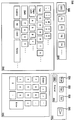
도 10은 패널 서브유닛에 기초한 본 발명에 의해 디스플레이된 예시적인 사용자 인터페이스를 보여주고, 온-스크린 키보드를 나타내는 도면.10 shows an exemplary user interface displayed by the present invention based on a panel subunit, and shows an on-screen keyboard.
도 11은 본 발명에 따른 도 10의 온-스크린 키보드 예를 생성하기 위한 예시 적인 패널 서브유닛 설명자 정보를 나타내는 도면.FIG. 11 illustrates exemplary panel subunit descriptor information for generating the on-screen keyboard example of FIG. 10 in accordance with the present invention. FIG.
도 12는 본 발명의 패널 서브유닛에 따른 예시적인 단계 및 지능 제어기와 원격 목표 장치 사이의 통신을 나타내는 도면.12 illustrates exemplary steps and communication between an intelligent controller and a remote target device in accordance with a panel subunit of the present invention.
본 발명에 다음의 상세한 설명에서는, 가전 장치의 네트워크 내에서 지능 제어기를 통해 목표 장치와 원격으로 인터페이싱하기 위한 패널 서브유닛이 본 발명의 완전한 이해를 제공하기 위해 다양한 상세한 설명으로 진술된다. 그러나, 본 발명이 이러한 상세한 설명 없이도 그것에 대해 동일하게 실행될 수 있다는 사실이 당업자들에게 인지될 것이다. 다른 예에 있어서, 널리 공지된 방법, 절차, 성분, 및 회로들은 본 발명의 취지를 필요 없이 불명확하게 하지 않도록 하기 위해 상세하게 설명되지 않는다.In the following detailed description of the invention, a panel subunit for remotely interfacing with a target device via an intelligent controller in a network of consumer electronic devices is set forth in various detailed descriptions to provide a thorough understanding of the invention. However, it will be appreciated by those skilled in the art that the present invention may be practiced identically thereto without this detailed description. In other instances, well known methods, procedures, components, and circuits have not been described in detail in order not to unnecessarily obscure the spirit of the present invention.
본 발명은 임의의 호환 장치(일예로, "목표 장치")가 제어 요소 및 디스플레이 요소 등을 포함하는 물리적인 외양을 외부 지능 제어기 장치에 묘사하도록 하는 패널 서브유닛으로 도시된다. 목표 장치는 지능 제어기로부터 멀리 위치될 수 있다. 또한 지능 제어기는 목표 장치를 위한 사용한 인터페이스를 생성하는데, 상기 목표 장치는 1)대화식 제어 요소; 및 2)목표 장치에 관련한 사용자 디스플레이 정보를 포함한다. 패널 서브 유닛은 지능 제어기로 하여금 마치 사용자가 목표 장치의 제어 요소를 물리적으로 조정한 것처럼 목표 장치에 동작을 트리거하도록 한다. 지능 제어기와 목표 장치는 동일한 통신 네트워크에 연결된다(일예로, IEEE 1394 직렬 표준을 사용하여). 또한 본 발명은 널리 공지된 AV/C 명령 및 제어 프로토콜을 지원하는 임의의 장치들 사이의 높은 수준의 상호운용 가능성을 증진시키기 위해 일 실시예에서 사용될 수 있다.The present invention is shown as a panel subunit, which allows any compatible device (eg, "target device") to depict to the external intelligent controller device the physical appearance including control elements, display elements, and the like. The target device may be located far from the intelligent controller. The intelligent controller also creates a used interface for the target device, the target device comprising: 1) an interactive control element; And 2) user display information related to the target device. The panel subunit causes the intelligent controller to trigger an action on the target device as if the user had physically adjusted the control elements of the target device. The intelligent controller and the target device are connected to the same communication network (eg, using the IEEE 1394 serial standard). The invention may also be used in one embodiment to enhance the high level of interoperability between any devices that support the well-known AV / C command and control protocol.
일반적으로, 본 발명은 지능 제어기로 하여금 목표 장치의 패널 서브유닛과 통신하도록 하고, 일예로 버튼, 슬라이더 등과 같은 여러 유형의 제어 요소에 대해 질의한다. 또한 지능 제어기는 디스플레이 상에서 이러한 제어 대상 설명에 기초한 휴먼 인터페이스를 생성하고, 사용자가 이러한 휴먼 인터페이스를 조정할 때, 제어기는 특별한 사용자 이벤트를 목표 장치로 보낸다. 지능 제어기에 의해 디스플레이될 수 있는 정보는 디스플레이된 휴면 인터페이스가 지능 제어기 장치의 특정 디스플레이 성능에 적합하도록 목표 장치에 의해 크기조정이 가능하다. 지능 제어기는 사용자에게 보여진 가장 최근의 상태를 유지하기 위해 목표 장치를 모니터링한다.In general, the present invention allows an intelligent controller to communicate with a panel subunit of a target device and, for example, inquires about various types of control elements such as buttons, sliders and the like. The intelligent controller also creates a human interface based on this controlled object description on the display, and when the user adjusts this human interface, the controller sends a special user event to the target device. The information that can be displayed by the intelligent controller can be scaled by the target device such that the displayed dormant interface is suitable for the specific display capabilities of the intelligent controller device. The intelligent controller monitors the target device to maintain the most recent state shown to the user.
따라서, 지능 제어기는 목표 장치에서 임의의 구체적 특성에 대한 사전 지식이나 그것들이 어떻게 사용되거나 실시되는지에 대한 사전 지식을 가질 필요가 없는데, 그 이유는 이러한 기능은 목표 장치의 임무이기 때문이다. 상태 변환 및 상호-제어 종속과 같은 모든 문제는 지능 제어기의 임무와는 관계없이 목표 장치에 의해 자동적으로 처리된다. 본 발명은 상태 변환 표 및 실행 환경과 같은 아이템들에 대한 모든 요구조건을 제거하는데, 그 이유는 본 발명이 이미 미디어 장치에 장착되어 있고 물리적인 버튼이 사용자에 의해 조정될 때 상기 물리적인 버튼을 다루기 위해 사용되는 기능을 이용하기 때문이다. 일예로, 지능 제어기가 "버튼 5 누름을 시뮬레이팅하는 것"을 목표에 요청하였을 때, 지능 제어기는 사용자 동작이 통보되는 목표 장치에서 발생하는 것에 대해서 조금도 어떠한 지식을 가질 필요가 없다. "버튼 5"가 눌려졌을 때 발생하는 모든 것에 대한 상태 변환 논리는 목표 장치에 모두 포함된다. 이것은 상기 상태 변환 논리가 각 임무를 동시에 상당히 감소시키는 동안 지능 제어기와 목표 장치 사이의 상호-기능을 향상시키기 때문에 유리하다.Thus, the intelligent controller does not need to have prior knowledge of any specific characteristics or how they are used or implemented in the target device, since this function is the task of the target device. All problems such as state transitions and inter-control dependencies are automatically handled by the target device regardless of the task of the intelligent controller. The present invention removes all the requirements for items such as state transition tables and execution environments because the present invention is already mounted on the media device and dealing with the physical buttons when the physical buttons are adjusted by the user. This is because it uses the function used for the purpose. For example, when the intelligent controller requests the target to “simulate a
물리적인 제어 요소와 외양을 기술하는 것 외에도, 본 발명은 논리 제어 요소 및 논리 제어 패널 요소에 대한 외양을 기술하기 위해 사용될 수 있다. 일예로, 논리 제어 패널은 임의의 물리적인 제어 요소를 갖지 않지만 작은 방이나 다른 먼 지점에 위치되는 블랙 박스와의 1394 연결기만을 구비하는 "블랙 박스"를 제어하기 위해 사용될 수 있다. 이러한 경우에, 블랙 박스는 패널 서브유닛을 통해 온 스크린 제어 요소로 조정되고, 그럼으로써 어떠한 물리적인 제어 패널 그 자체도 갖지 않는다.In addition to describing physical control elements and appearances, the present invention can be used to describe appearances for logic control elements and logic control panel elements. In one example, a logic control panel may be used to control a "black box" that does not have any physical control elements but only has a 1394 connector with a black box located in a small room or other distant point. In this case, the black box is adjusted to the on-screen control element via the panel subunit, thereby having no physical control panel itself.
본 발명의 네트워크 환경Network environment of the present invention
도 1은 본 발명의 패널 서브유닛에 대한 실시예를 지원할 수 있는 예시적인 네트워크 시스템(5)을 나타내고 있다. 예시적인 시스템(5)은 노드로서 가전 장치(컴퓨터 시스템을 포함)를 포함하지만 다른 전자 장치를 포함하기 위해 동일하게 잘 확장될 수 있다. 시스템(5)은 비디오 카메라(10), 비디오카세트 레코더(VCR)(12), 컴퓨터 시스템(14), 셋-톱-박스(STB)(13), 텔레비전 세트(TV)(11) 및 컴팩트 디스크(CD) 교환기(20)를 포함하고, 그것들은 모두 IEEE 1394-1995(IEEE 1394) 케이블(15,16,18 및 19)에 의해 네트워크로 연결된다. 본 발명의 패널 서브유닛 실시예가 임의의 버스 구조와의 응용에 대해 매우 동일하게 적용되고, IEEE 1394 버스 구조는 단지 예시적인 버스 구조로서 본 명세서에서 도시되어 기술된다는 것이 인식된다. STB(13)은 케이블 TV 시스템으로부터 미디어를 수신하기 위해 연결될 수 있다. IEEE 1394 케이블(16)은 비디오 카메라(10)를 VCR(12)에 연결하여, 비디오 카메라(10)가 데이터, 명령 및 파라미터들을 기록하기 위해 VCR(12){또는 네트워크(5)의 임의의 다른 장치}에 보내도록 한다. IEEE 1394 케이블(18)은 VCR(12)를 컴퓨터 시스템(14)에 연결하여, VCR(12)이 데이터, 명령 및 파라미터를 디스플레이를 위해 컴퓨터 시스템(14){또는 네트워크(5)의 임의의 다른 장치}에 보내도록 한다.1 shows an
IEEE 1394 케이블(15)은 STB(13)을 컴퓨터 시스템(14)에 연결한다. STB(13)은 케이블(17)을 통해 TV(11)에 또한 연결된다. CD 교환기(20)는 IEEE 1394 케이블(19)을 통해 컴퓨터 시스템(14)에 연결된다. 도 1에 도시된 구성(5)은 단지 예시적인 것이고, 본 발명에 따른 오디오/비디오 네트워크는 많은 다양한 성분들의 결합을 포함할 수 있다는 것이 명확해질 수 있다. IEEE 1394 네트워크(5) 내의 장치들은 자동 장치이고, 이는, IEEE 1394 네트워크에서 컴퓨터는 상기 장치들 중의 하나이며, 컴퓨터 시스템(14)과 다른 장치들 사이에는 사실상 주-종 상호관계가 없다는 것을 의미한다. 사실, 본 발명의 패널 서브유닛에 대한 예시적인 실시예에서 아래에 기술된 것처럼, 지능 제어기는 STB(13)이다. 많은 IEEE 1394 네트워크 구성에서, 컴퓨터 시스템(14)은 제공되지 않을 수 있다. 이러한 구성에서조차도, 네트워크 내의 장치들은 피어-투-피어 방식으로 완벽하게 서로 상호작용 할 수 있다. 데이터, 명령 및 파라미터들은 IEEE 1394 네트워크(5) 내에서 모든 장치들 사이에 보내질 수 있다는 사실이 인지되어야 한다.An IEEE 1394
도 1의 시스템(5)에 사용된 IEEE 1394 직렬 버스는 디지털 장치들의 상호연결을 위한 고속 버스 구조이기 때문에 범용 입/출력 연결을 제공한다. IEEE 1394 표준은 응용을 위한 디지털 인터페이스를 한정함으로써 디지털 데이터가 버스를 통해 전송되기 전에 디지털 데이터를 아날로그 데이터로 변환하는 응용장치들에 대한 필요성을 제거한다. 따라서, 수신용 장치는 버스로부터 아날로그 데이터가 아닌 디지털 데이터를 수신하고, 그러므로 아날로그 데이터를 디지털 데이터로 변환할 필요가 없다. IEEE 1394 표준에 의해 요구되는 케이블은 이러한 장치를 연결하기 위해 사용되는 다른 더 큰 케이블에 비해 크기면에서 매우 얇다. 장치들은 버스가 동작되어있는 동안 IEEE 1394 버스에 추가될 수도 있고 제거될 수도 있다. 만약 장치가 추가되거나 제거된다면, 버스는 현존하는 노드들 사이에서 데이터를 전송하기 위해 그 자체를 자동적으로 재구성한다. 노드는 버스 구조상에 유일한 주소를 갖는 국부적인 실체로 간주된다. 각 노드는 식별 ROM, 표준화된 제어 레지스터군 및 각 노드의 주소 공간을 제공한다.The IEEE 1394 serial bus used in the
도 1의 시스템(5)에서의 IEEE 1394 통신 표준은 디지털 인코딩 정보의 등시성 데이터 전달을 지원한다. 등시성 데이터 전달은 유효 거리 사이의 시간 간격이 전송 및 수신 장치 모두에서 동일한 지속시간을 갖도록 하기 위해 발생하는 실-시간 전송이다. 등시적으로 전달된 각 패킷은 상기 각 패킷의 시간 주기로 전달된다. 등시적인 데이터 전달에 대한 응용장치의 예는 도 1에서 VCR(12)로부터 TV(11)까지이다. VCR(12)는 이미지와 음성을 기록하고, 각 패킷에 데이터를 저장한다. 또한 VCR(12)는 TV(11)에 의한 디스플레이를 위해 상기 시간 주기 동안에 제한된 시간 주기에 걸쳐 기록된 이미지와 음성을 나타내는 각 패킷을 전달한다. IEEE 1394 표준 버스 구조는 응용장치들 사이의 등시적인 데이터 전달을 위해 다중 채널을 제공한다. 특히, 6비트 채널 번호가 적절한 응용장치에 의한 수신을 보장하기 위해 데이터와 함께 방송된다. 이러한 사실은 다중 응용장치로 하여금 버스 구조를 통해 등시성 데이터를 동시에 전송하도록 한다. 비동기적인 전달은 전통적인 데이터 전달 동작이며, 상기 전통적인 데이터 전달 동작은 가능한 한 빨리 발생하고 다량의 데이터를 소스로부터 목적지에 전달한다.The IEEE 1394 communication standard in the
지능 제어기Intelligent controller
본 발명의 패널 서브유닛에 대한 사용자 인터페이스 취지는 지능 제어기 장치에서 구현된다. 지능 제어기는 사용자에 의해 지정되고 특정 기본 입력 기능 및 기본 디스플레이 성능을 구비하는 네트워크로 구성된 시스템{일예로, 도 1의 시스템(5)}에 연결된 임의의 장치일 수 있다. 본 발명의 일 실시예에서, STB(13)과 TV(11)는 지능 제어기로서 동작한다. 다른 실시예에서는, 컴퓨터 시스템(14)이 지능 제어기로서 동작할 수 있거나 또는 TV(11)가 지능 제어로서 동작할 수 있다. "디스플레이"와 입력 성능을 구비하는 임의의 장치{일예로 개인 휴대용 정보 단말기(PDA : personal digital assistant), 휴대용 전자 장치, 셀 전화기 등}는 지능 제어기로 동작할 수 있다. 본 발명의 전후관계에 있어서, 지능 제어기는 네트워크(5) 내의 또 다른 원격 목표 장치에서 이벤트를 제어하기 위한 사용자 인터페이스를 제공하는 장치이다. 이러한 범위에서, 지능 제어기는 디스플레이 장치 및 정보 입력 장치와 통신한다. 지능 제어기 장치의 디스플레이 및 입력 성능은 상기 지능 제어기가 사용자에게 제공할 수 있는 사용자 인터페이스의 유형을 한정하고, 본 발명의 패널 서브유닛은 크기조정이 가능한 사용자 인터페이스 성능을 한정한다.The user interface intent for the panel subunit of the present invention is implemented in an intelligent controller device. The intelligent controller may be any device that is specified by a user and connected to a system (eg,
도 2는 본 예에서는 STB(13)인 지능 제어기의 구성 성분을 기술하고 있다. STB(13)은 정보를 전달하기 위한 주소/데이터 버스(100), 정보 및 명령을 처리하기 위해 버스(100)와 연결된 중앙 처리기(101), 상기 중앙 처리기(101)에 대한 정보 및 명령을 저장하기 위해 버스(100)에 연결된 휘발성 메모리(102){일예로, 임의 접속 메모리(RAM)} 및 처리기(101)에 대한 정적 정보(static information)와 명령을 저장하기 위해 버스(100)에 연결된 비-휘발성 메모리(103){일예로, 판독 전용 메모리(ROM)}를 포함한다. 또한 STB(13)는 정보 및 명령을 저장하기 위해 버스(100)에 연결된 자기 또는 광 디스크와 디스크 드라이브와 같은 데이터 저장 장치(104)("디스크 서브시스템")를 선택적으로 포함한다. 일 실시예에서, 디스플레이 장치(105)는 지능 제어기의 일부분일 수 있다. 도 2에서 도시된 것처럼, 디스플레이 장치{일예로, TV(11)}는 STB(13)의 외부에 장착된다. 지능 제어기에 병합되었을 때, 디스플레이 장치(105)는 디스플레이 스크린(일예로, 평평한 패널이나 CRT 등)이거나 문자-숫자식 및/또는 그래픽 정보를 디스플레이하기 위한 액정 디스플레이(LCD) 패널 또는 다른 적합한 디스플레이 장치일 수 있다.2 illustrates the components of the intelligent controller, which is
지능 제어기(13)는 하나 이상의 사용자 입력 장치와 또한 인터페이스하거나 포함한다. 일 실시예에서, 입력 장치는 정보 및 명령 선택을 중앙 처리기(101)에 전달하기 위해 버스(100)에 연결된 문자-숫자 키와 기능 키를 구비하는 문자 숫자식 입력 장치(106)일 수 있다. 대안적으로 또는 부가적으로, 지능 제어기(13)는 사용자 입력 정보와 명령 선택을 중앙 처리기(101)에 전달하기 위해 버스에 연결된 커서 제어 장치나 커서 유도 장치(107)와 인터페이스 하거나 또는 포함할 수 있다. 커서 유도 장치(107)는 마우스, 트랙 볼, 트랙 패드, 전자 패드 및 스타일러스, 광 트랙킹 장치, 터치 스크린 등과 같이 널리 공지된 다수의 장치들을 사용하여 구현될 수 있다. 게다가, 사용자 입력 장치는 또한 일예로 다수의 버튼, 다이얼 등을 갖는 범용 원격 제어 장치와 같은 적외선 신호 전달 성능을 구비한 원격 제어 장치일 수 있다. STB(13)는 IEEE 1394 버스를 통해 네트워크로 구성된 다른 장치들과 인터페이싱하기 위해 버스(100)에 연결된 신호 생성 장치(108)를 또한 구비할 수 있다.The
본 발명의 목표 장치는 도 2에 대해 기술된 것처럼 하나 이상의 성분을 또한 구비할 수 있다. 특히, 본 발명에 따른 목표 장치는 컴퓨터 판독가능 메모리 유닛을 구비하는데, 상기 컴퓨터 판독가능 메모리 유닛은 이후에 기술되는 본 발명의 패널 서브유닛 정보를 저장하기 위한 하나 이상의 ROM 및/또는 RAM 유닛을 구비할 수 있다.The target device of the present invention may also have one or more components as described for FIG. 2. In particular, the target device according to the present invention comprises a computer readable memory unit, wherein the computer readable memory unit has one or more ROM and / or RAM units for storing the panel subunit information of the present invention described later. can do.
본 발명의 패널 서브유닛Panel subunit of the present invention
본 발명은 "패널" 서브 유닛으로 호칭되는 서브유닛 유형을 한정한다. 상기 패널 서브유닛은 목표 장치를 위해 한정되고, 네트워크 시스템(5)의 지능 제어기 장치{일예로, STB(13)}에 사용자 인터페이스를 생성하는 것에 대한 특성을 약술한다. 패널 서브유닛은 다수의 목표 장치에 대해서 한정될 수 있기 때문에 많은 패널 서브유닛이 네트워크 시스템(5)에 포함될 수 있다. 특정 목표 장치를 위해서, 상기 목표 장치의 패널 서브유닛은 특정 목표 장치의 컴퓨터 판독가능 메모리 유닛에 데이터 구조로서 저장될 수 있다.The present invention defines a subunit type called "panel" subunit. The panel subunit is defined for the target device and outlines the characteristics for creating a user interface in the intelligent controller device (eg, STB 13) of the
도 3a는 예시적인 목표 장치로서 도 1의 VCR(12)을 사시도로 나타내고 있다. 비록, 일반적으로는 임의의 전자 장치가 그 자체의 패널 서브유닛을 구비할 수 있기 때문에 "목표 장치"일 수 있지만, 다음의 논의는 VCR(12)이 목표 장치인 예시적인 경우를 기술하고 있다. VCR(12)은 비디오 테이프 미디어의 삽입 및 제거를 위한 비디오 테이프 슬롯(212)을 포함한다. 또한 VCR(12)은 하나 이상의 액정 디스플레이(LCD)(214)를 포함한다.3A shows in perspective view the
도 3b는 특정 제어 요소와 다른 디스플레이 요소(일예로, "요소들")를 진열하기 위한 플립-다운형의 제어 패널(220)을 구비하는 VCR(12)을 도시한다. 제어 패널(220)은 다른 LCD 디스플레이(240)를 포함하고 스크러버(scrubber) 제어 요소(230)나 "다이얼"을 포함한다. 제어 패널(220)은 특정 테이프 운반 제어 요소(250)(재생, 일시 정지, 멈춤, 되감기, 앞으로 빨리 감기, 버튼 등)를 또한 포함한다. 제어 패널(220)이 플립 다운되었을 때, 상기 패널(220)은 튜너 프리셋 버튼(225)을 진열한다. 본 발명에서, 장치들은 하나 이상의 논리 제어 패널을 가질 수 있다. 이러한 구성에서, VCR(12)는 두 개의 논리 서브패널을 갖는다. 제 1 서브패널은 플립-다운형 제어 패널(220)의 제어 요소와 디스플레이 요소를 포함하고, 제 2 서브패널은 테이프 슬롯(212)과 튜너 프리셋 버튼(225)을 포함한다. 또 다른 서브패널은 LCD 패널(214)을 한정할 수 있다.3B shows a
도 4는 본 발명에 따른 VCR(12)과 결합될 수 있는 일부 서브유닛의 논리 블록도를 나타내고 있다. 널리 공지된 AV/C 프로토콜에서, 서브유닛들은 개별적으로 주소지정될 수 있고 장치 내에서 제어될 수 있는 물리적이지 않은 논리적인 기능 그룹들이다. 일예로, VCR 장치(12)는 두 개의 서브유닛을 구비할 수 있는데, 하나의 서브유닛(312)은 실제적인 VCR 테이프 운반 메커니즘을 위한 것이고 다른 서브유닛(320)은 튜닝 기능을 위한 것이다. 본 발명의 패널 서브유닛(314)은 VCR 장치(12)와 결합될 수 있는 새로운 논리 서브유닛을 추가한다. 이하에서 더 설명되고 있는 것처럼, 본 발명의 패널 서브유닛(314)은, 일 실시예에서, 일예로 VCR 유닛(12)과 같은 목표 장치의 컴퓨터 판독가능 메모리 유닛에 저장된 하나 이상의 데이터 구조로써 실행된다. 제 1 장치(일예로, 제한된 메모리 용량의)의 패널 서브유닛이 제 2 장치(더 많은 메모리 용량을 구비하는)에 배치되는 것이 가능하기 때문에, 제 2 장치는 제 1 장치의 패널 서브유닛을 위한 프록시로서 동작한다.4 shows a logic block diagram of some subunits that may be combined with a
패널 서브유닛(314)은 목표 장치(일예로, 제어 패널) 상의 물리적인 제어 요소를 나타내고 "설명자"로 호칭되는 데이터 구조의 집합(collection)이다. 동작 중에, 지능 제어기{일예로, STB(13)}는 목표 장치의 패널 서브유닛(314)에 억세스하고, 그것에 기초하여 목표 장치{일예로, VCR(12)}를 사용하기 위해 사용자 인터페이스를 구현한다. 사용자 인터페이스는, 도 2에 관하여 기술된 것처럼, 디스플레이{일예로, TV(11)}와 지능 제어기와 결합된 사용자 입력 장치를 수반한다. 패널 서브유닛(314)에 대한 설명은 가전 장치에 일반적으로 장착되는 누름 버튼, 슬라이더, 다이얼, LCD 스크린 등과 같은 제어 요소 및 디스플레이 요소들에 대한 수 개의 표준 유형을 한정한다. 일예로서, VCR(12)을 위한 패널 서브유닛(314) 내의 설명은 도 3a 및 도 3b의 버튼, 다이얼 및 LCD 스크린을 나타낼 수 있다.
패널 서브유닛(314)으로 한정된 제어 유형은 동작을 잘 한정하고 있다. 일예로, 버튼은 눌려지고 누름해제되며 일반적으로 두 개의 값을 갖고, 슬라이더는 수 개의 이산적인 값이나 연속적인 값의 영역을 가질 수 있다. 또한, 일부 표준 제어 유형은 하이브리드나 주문형 제어 요소를 형성하기 위해 설명자에 결합될 수 있다. 이것들에 대한 일예로는 중간에 누름 버튼을 갖는 다이얼이나 중간에 LED을 갖는 버튼이 있다. 이러한 복합적인 제어 메커니즘은 본 발명의 패널 서브유닛에 의해 지원된다. 결국, 벤더 특정 주문형 제어요소(vendor specific custom controls)가 또한 한정될 수 있다.The type of control defined by the
표준 제어 유형 외에도, 본 발명의 패널 서브유닛(314)이 이러한 제어 요소 중 임의의 제어 요소에 적용될 수 있는 명령군을 또한 한정한다. 상기 명령은 대부분 유형의 제어 요소에 적용되기 위해서 충분히 포괄적으로 한정된다. 일예로, 지능 제어기를 통해 명령 "제어값 설정(SET CONTROL VALUE)"(제어 1, 6)을 등록함으로써 볼륨 슬라이더는 값(6)으로 설정될 수 있고, 이것은 볼륨에 있어서의 변화를 나타낸다. 마찬가지로, 다른 피연산자를 갖는 동일한 명령 유형이 "제어 값 설정"(제어 5, "트랙 명을 입력하시오")으로 등록될 수 있고, 이것은 그 텍스트(text)로 하여금 미니디스크 레코더(20)의 LCD 디스플레이에 나타나도록 야기하여, 사용자가 디스크에 트랙에 대한 이름을 입력하도록 촉구할 수 있다. 또한, 패널 서브유닛에서, 일부 명령은 특별한 종류의 제어 요소에 대해서 특정화될 수 있다.In addition to the standard control types, the
패널 서브유닛(314)은 사용자 인터페이스의 제어 요소에 적용될 수 있는 "사 용자 상호작용 명령" 나 사용자 이벤트를 또한 한정한다. 이러한 포괄적인 사용자 이벤트의 목적은 제어 요소에 대한 일반적인 사용자 조정 동작을 요약하고, 목표 장치로 하여금 그것이 의미하는 바와 이러한 사용자 이벤트가 발생하는 때를 해석함으로써 지능 제어기가 이러한 임무를 배제하도록 하도록 한다. 일예로, 많은 CD 재생기(20)가 그 순간의 장치의 상태에 따라 빨리 감기 버튼에 대해 많은 의미적인 중요성을 갖는다.The
표 ITable I
위에 도시된 것처럼, 목표 장치를 통해 행해진 동작은 상기 장치의 현 상태와 사용자가 물리적인 제어 요소로 무엇을 하는가에 기초하여 달라진다. 본 발명의 패널 서브유닛은 디스플레이된 사용자 인터페이스의 사용자 상호작용에 의해 트리거되는 "누름", "누름 및 유지", 및 "누름해제"와 같은 일부 사용자 동작 명령을 한정한다. 본 발명에 따라, 본 발명의 지능 제어기는 목표 장치에 등록된 명령에 대한 응답으로 상기 목표 장치가 무엇을 행할 것인지에 대해 어떠한 이해관계도 갖지 않는다. 표 I에 도시된 것과 같은 상태 전이에 관한 모든 이해관계가 목표 장치의 내부에서 다루어진다. 목표 장치는 물리적인 제어 패널 상의 사용자 상호작용을 처리하기 위해 이러한 논리를 적절한 위치에 미리 가질 필요가 있다는 것이 인지된다. 본 발명의 패널 서브유닛은 이러한 논리적인 입력 점에 억세스하기 위한 또 다른 메커니즘으로써 고찰된다.As shown above, the actions performed through the target device vary based on the current state of the device and what the user does with the physical control element. The panel subunit of the present invention defines some user action commands, such as "press", "press and hold", and "release" triggered by user interaction of the displayed user interface. According to the present invention, the intelligent controller of the present invention has no interest in what the target device will do in response to a command registered in the target device. All interests regarding state transitions, such as those shown in Table I, are addressed inside the target device. It is recognized that the target device needs to have this logic in place beforehand in order to handle user interaction on the physical control panel. The panel subunit of the present invention is contemplated as another mechanism for accessing this logical input point.
지능 제어기는 제어되는 목표 장치의 상태에 관하여 사용자가 항상 알 수 있도록 하는 것이 중요하다. 일 실시예에서, 지능 제어기와 사용자가 집이나 회사 사무실에서 한 방에 위치하고, 목표 장치가 다른 방이나 사무실에 위치되는 것이 가능하다. 지능 제어기는 사용자 상호작용 요소들을 어떻게 해석하는지에 대해 사전에 한정된 지식을 갖지 않기 때문에, 가장 최근의 목표 장치의 상태를 통해 갱신된 디스플레이를 유지하기 위한 메커니즘을 가질 필요가 있다. 이러한 사실은 AC/C 프로토콜에 대해 한정된 상태보고 메커니즘을 이용하여 이루어지고, 일 실시예에서는 본 발명에 따른 상태 설명자 데이터 구조와 패널 상태 통보 명령을 사용하여 이루어진다.It is important that the intelligent controller always keeps the user informed about the state of the controlled target device. In one embodiment, it is possible for the intelligent controller and the user to be located in one room at home or work office, and the target device in another room or office. Since the intelligent controller does not have a limited knowledge of how to interpret the user interaction elements, it is necessary to have a mechanism for maintaining the updated display through the state of the most recent target device. This is done using a state reporting mechanism defined for the AC / C protocol, and in one embodiment using a state descriptor data structure and a panel state notification command in accordance with the present invention.
상태 설명자 데이터 구조는 본 발명의 패널 서브유닛(314)에 의해 항상 최근의 데이터 구조로 유지되는 다이내믹 데이터 구조이다. 지능 제어기는 목표 장치의 상태를 사용자에게 나타내기 위해 그것의 그래프식 디스플레이를 갱신할 수 있도록 아무때나 이 구조를 조사할 수 있다. 본 발명의 패널 상태 통보 명령은 지능 제어기로 하여금 목표 장치에 통보 요청을 알려주도록 한다. 장치에서의 임의의 상태 변화가 상태 설명자 데이터 구조에 변화를 초래하였을 때, 목표 장치는 지능 제어기에 통보한다. 그 때 지능 제어기는 상태 정보에 대한 응답으로 적절하게 자신의 그래프식 디스플레이를 갱신한다.
AV/C 프로토콜은 장치(본 명세서에서는 유닛이라 또한 호칭됨)가 동일한 유형의 서브유닛을 임의의 수만큼 보유하도록 한다. 그러므로, 장치는 본 발명의 하나 이상의 패널 서브유닛을 가질 수 있다. 일예로, 하나의 패널 서브유닛은 도 3b의 전면 패널로 한정될 수 있고, 또 다른 패널 유닛은 플립-다운형 패널(220)로 한정될 수 있다. 만약 있다면, 다른 패널 유닛은 측후면 패널로 한정될 수 있다. 대안적으로, 단일 패널 서브유닛은 도 5에 도시된 것처럼 수 개의 제어 요소를 내포하기 위해 한정될 수 있다. 이러한 접근 방법에 있어서, 단일 패널 서브유닛은 계층적으로 순서가 매겨지는 임의의 수의 제어 리스트를 포함할 수 있다. 본 발명의 각 제어 리스트는 목표 장치의 제어 패널을 나타낸다. 이러한 모든 리스트들은 단일 패널 서브유닛(314)을 통해 억세스된다.The state descriptor data structure is a dynamic data structure that is always kept in the latest data structure by the
The AV / C protocol allows a device (also referred to herein as a unit) to hold any number of subunits of the same type. Therefore, the device may have one or more panel subunits of the invention. As an example, one panel subunit may be defined as the front panel of FIG. 3B and another panel unit may be defined as flip-down
패널 서브유닛 데이터 구조의 일부분이 배열(layout) 이미지와 패널 및 제어 요소의 방향을 나타내는 기하학적인 정보를 포함함으로써, 상기 정보는 목표 장치 상에서의 정보의 물리적인 외양과 유사한 방식이나 목표 장치에 의해 "제시되는" 방식으로 사용자에게 나타내질 수 있다. 표준 제어 요소가 하이브리드 제어 요소로 결합됨으로써, 이러한 기하학적인 정보는 전면 플립-다운 면(220)(도 3b)의 뒤에 숨겨진 패널과 같은 패널 계층의 존재를 나타내기 위해 정의될 수 있다. 이러한 패널 계층은 일부 기본 제어 요소가 VCR 장치의 표면에 위치하고 더 많은 개선된 제어 요소 및 특징이 플립-다운형 전면 패널(220)의 뒤에 숨겨진 많은 VCR 장치에서 일반적으로 발견된다.As part of the panel subunit data structure includes layout images and geometric information representing the orientation of the panels and control elements, the information may be generated by a target device or in a manner similar to the physical appearance of the information on the target device. Presented to the user in the manner presented. By combining a standard control element into a hybrid control element, this geometric information can be defined to indicate the presence of a panel hierarchy such as a panel hidden behind the front flip-down face 220 (FIG. 3B). This panel hierarchy is commonly found in many VCR devices where some basic control elements are located on the surface of the VCR device and more advanced control elements and features are hidden behind the flip-down
패널 서브유닛의 패널 설명자Panel descriptor of panel subunit
도 5는 일예로 VCR(12)과 같은 목표 장치의 컴퓨터 판독가능 메모리 유닛에 의해 보존되는 데이터 설명자 정보를 나타내고 있다. 도 5 내지 도 8 및 도 11에서 보여진 데이터 설명자 데이터 구조는 모두 유지되고, 본 발명에 따라 목표 장치의 컴퓨터 판독가능 메모리 유닛 내에서 실행된다는 것이 인지된다. 패널 서브유닛(314)(도 4)은 패널 서브유닛 식별자 설명자 데이터 구조(340)를 포함한다. 상기 식별자 설명자 리스트(340)는 패널 서브유닛(314)에 의해 지원되는 주 패널 리스트들의 각각에 대한 식별자를 나타낸다. 각각의 이러한 패널 리스트들은 패널 계층을 나타내는 자식 리스트(child list)를 구비한 제어 대상을 보유할 수 있다. 일예로, 제 1 식별자 리스트(340)는 목표 장치에 대한 전면 패널에 관한 것이고, 두 개의 서브-패널 설명{일예로, 하나는 VCR(12)의 면을 위한 것이고 다른 하나는 플립-다운형 패널(220)을 위한 것}을 구비하는 제 2 식별자 구조(350)를 가리키는 식별자(일예로, 포인터)(342)를 포함한다. 또한 제 1 식별자(340)는 목표 장치에 대한 후면 패널을 나타내는 다른 제 2 식별자 리스트(390)를 위한 식별자(일예로, 포인터)(344)를 포함한다. 이러한 방식으로, 패널 서브유닛(314)의 제 1 식별자와 제 2 식별자 구조는 설명자 리스트 정보 사이의 계층적인 상호관계를 한정할 수 있고, 그럼으로써 패널과 서브-패널 사이의 계층적인 상호관계를 한정할 수 있다.5 shows data descriptor information stored by a computer readable memory unit of a target device such as
도 5의 제 2 식별자 설명자 리스트(350)는 일반적인 리스트 정보 필드(352)와 LCD 디스플레이(214)(도 3a)를 설명하기 위한 하나의 대상 제어 설명자(354)를 포함하는 설명자 리스트이다. 본 발명 내의 설명자 리스트는 대상 제어 설명자, 일반적인 정보, 및 자식(child) 설명자 리스트를 가리키는 포인터를 포함할 수 있다. 그러므로, 설명자 리스트 내의 제어 대상은 제어 대상과 지시된 설명자 리스트 사이의 부모-자식 상호관계를 나타내는 또 다른 설명자 리스트를 가리킬 수 있다. 설 명자 리스트(350)는 이러한 예에서 VCR(12)에 대한 전면 패널의 제어 요소 부분인 "서브-패널 1"을 기술하기 위해 사용되는 자식 설명자 리스트(356a)를 나타내는 포인터(356)를 포함한다. 또한, 설명자 리스트(350)는 VCR(12)에 대한 전면 패널의 또 다른 제어 요소 부분인 "서브-패널 2"를 기술하기 위해 사용되는 자식 설명자 리스트(358a)를 나타내는 포인터(358)를 포함한다. 이러한 예에 있어서, 서브-패널 1을 위한 설명자 리스트(356a)는 튜너 서브유닛(320)을 위해서 일예로 버튼(225)과 같은 제어 요소를 VCR(12)의 표면에 한정한다. 서브-패널 2를 위한 설명자 리스트(358a)는 일예로 버튼(250), 디스플레이(240), 및 다이얼(230)과 같은 제어 요소를 VCR(12)의 플립-다운형 제어 패널(220)에 한정한다.The second
임의의 설명자 리스트 데이터 구조에서처럼, 각각의 설명자 리스트(356a 및 358a)는 일반적인 리스트 정보 필드(360 및 380)를 각각 포함하고, 제어 대상의 각 리스트를 또한 포함한다. 본 발명에 따라, 패널에 대한 제어 대상을 포함하는 리스트는 제어 패널 자체를 기술하기 위해 사용될 뿐만 아니라, 대상의 집합을 유지하기 위해 사용된다. 일반적으로, 집합(패널 설명)을 기술하는 정보는 (1)패널 식별자(일예로, 전면, 후면, 좌측면, 등); (2)기하학적인 패널 배열(일예로, 패널 사이즈, 제어 요소의 방향, 그룹들의 정의, 등); (3)패널 내의 그룹 레벨, 그룹 경계 박스/위치, 및 다른 그룹관련 정보를 한정할 수 있는 각 제어 요소 그룹에 대한 그룹 설명; 및 (4)패널 서브유닛에 대한 이름을 포함할 수 있다. 일예로 도 6에 도시되어 있다.As with any descriptor list data structure, each
도 6은 목표 장치의 전면 서브-패널 1에 대한 제 2 설명자 리스트(358a)의 일반적인 리스트 정보 데이터 구조(380) 내에 포함된 정보를 나타내고 있다. 제 2 설명자 리스트(358a)는 일반적인 리스트 정보(380)와 n개의 대상(382 내지 386)의 집합을 포함한다. 예시적인 데이터 구조(380)는 필드(410 내지 420)를 포함한다. 필드(410)는 필드가 포함되는 설명자 리스트(358a)를 위한 계층적인 위치나 식별자를 나타낸다. 일예로, 필드(410)는, 정보가 나타난 물리적 패널이 어떤 것인지를, 예를 들어 이러한 설명자 리스트(358a)가 전면, 측면, 후면, 등의 제어 패널을 나타내는 지의 여부를 나타낸다. 이 예에서 설명자 리스트(358a)는 "전면" 패널이다. 필드(412)는 설명자 리스트(358a)가 한정되는 제어 패널로의 억세스, 일예로 플립-다운, 플립-업, 플립-아웃, 좌측, 우측, 직접 억세스 등을 획득하기 위해서 사용되는 개방(opening) 또는 억세스 선택을 한정한다. 이 경우에, 제어 패널(220)(도 3b)은 "플립-다운" 형태의 억세스를 갖는다. 필드(414)는 설명자 리스트(358a)가 한정되는 제어 패널의 일반적인 사이즈와 형태(일예로, 직사각형, 원형, 타원형, 삼각형, 다각형 등)를 한정한다. 이 경우에, 제어 패널(220)은 형태에 있어서 직사각형이다.6 shows the information contained within the general list
도 6의 필드(416 내지 420)는 설명자 리스트(358a)가 한정되는 제어 패널 내의 그룹을 한정하기 위해 사용된다. 그룹은 유사한 특정 제어 특성을 분리하거나 유사 기능이나 특성을 제어하기 위해 사용될 수 있다. 일예로, VCR(12)의 채널 선택이나 볼륨 선택을 제어하는 버튼이 각 그룹으로 할당될 수 있는 반면에, VCR(12)을 위한 테이프 메커니즘의 제어에 각각 관련한 버튼은 하나의 그룹으로 할당될 수 있다. 그룹은 본 발명에서 특별한 기능을 갖는데, 일예로 상기 그룹은 지능 제어기 의 디스플레이 상에서 공간적으로 모두 디스플레이될 수 있고, 다른 한정된 속성을 공통적으로 갖는다. 필드(416)는 설명자 리스트 데이터 구조(358a)에 대해 한정된 그룹의 수를 나타내고, 필드(418 내지 420)는 다수의 예시적인 그룹들에 대한 그룹 설명 정보를 나타낸다.Fields 416-420 of FIG. 6 are used to define the group in the control panel where the
도 6은 예시적인 그룹(n-1)에 대해서 필드(420)에 포함된 예시적인 그룹 설명을 나타내는 필드(430 내지 438)를 나타낸다. 정보 필드(430)는 이 그룹에 대해 한정된 제어 대상의 수를 포함한다. 필드(432)는 그룹 식별 번호나 또는 이러한 그룹에 대해 고유하고 제어 대상을 통해 그룹을 식별하기 위해 사용되는 문자열(string)을 포함한다. 한정된 그룹에 포함될 각 제어 대상은 상기 제어 대상 설명(이후에 기술됨)에 식별자(432)를 포함한다. 필드(436)는 이러한 그룹이 제어 패널을 위해 포함되는 공간 경계 박스를 나타낸다. 이러한 정보는 이 그룹이 다른 한정된 그룹에 관해서 사용자 인터페이스 배열의 어디에 존재하는 지를 나타내고, 지능 제어기의 디스플레이 상에 제어 패널의 이미지를 렌더링하기 위해 사용된다. 필드(438)는 지능 제어기의 디스플레이 유닛이 이미지나 다른 정보를 제공하기에 충분히 정교하지 않은 경우에 대해서 이러한 그룹의 제어 대상에 억세스를 제공하고 또 나타내기 위해 사용될 수 있는 그룹 라벨이다. 필드(438)는, 일 실시예에 있어서, 정보의 탭(tabbed)된 패널 표현에서 탭 인덱스(tab index)로 사용될 수 있는 문자열이나 다른 텍스트 라벨을 일반적으로 포함한다. 탭된 패널 표현에 있어서, 모든 그룹에 대해 모든 한정된 탭은 디스플레이의 측면을 따라 디스플레이되고, 그룹은 하나의 탭이나 다른 탭을 선택함으로써 표현을 위해 선택될 수 있다.6 shows fields 430-438 representing example group descriptions contained in
도 7a는 본 발명의 패널 서브유닛에 따른 제어 대상(382)의 데이터를 나타내고 있다. 예시적인 제어 대상(382)은 설명자 리스트 데이터 구조(358a)에 포함된다. 일 실시예에 있어서, 본 발명의 패널 서브유닛은 AV/C 대상 및 대상 리스트 데이터 구조를 통해 자신의 정보를 제어기로 전달한다. 이 데이터 구조는 일반적인 컨테이너(container)이고, 상기 컨테이너의 내용은 구조의 소유자에 기초하여 전문화된다. 본 발명의 패널 서브유닛은 상기 유닛의 제어 요소 리스트{일예로, 리스트 설명자(385a)}를 포함하는데, 각 제어 요소는 제어 대상을 통해 리스트로 표기된다. 본 발명에서 제어 대상은 사용자 입력 장치(일예로, 버튼, 슬라이더, 토글 스위치 등..)를 나타내기 위해 한정될 수 있고, 또한 정보 디스플레이(일예로, LCD 패널, 다이얼 등..)를 나타내기 위해 한정될 수 있다.7A shows data of the
도 7a는 도 3a의 LCD 패널(214)을 나타내는 제어 대상(382) 정보를 나타낸다. 필드(440)는 한정될 제어 대상의 유형을 나타낸다. 이 경우에, 제어는 "LCD 패널" 유형이다. 정보를 디스플레이하기 위한 다른 제어 유형은 "디스플레이", "다이얼", "CRT 디스플레이", "LED" 및 "문자/숫자 디스플레이"를 포함한다. 정보 입력 장치를 위한 다른 제어 유형은 "버튼", "슬라이더", "로테이터(rotator)", 토글 스위치" 및 "록커(rocker) 스위치"를 포함한다. 필드(442)는 제어 대상의 그래픽 이미지를 포함한다. 이러한 이미지 정보는 일반적인 래스터(raster) 데이터(일예로, 비트 매핑된)이고 컬러 및 다른 속성의 데이터를 포함할 수 있다. 이러한 특별한 예에서, 제어 이미지(442a)는 LCD 패널(214)을 나타내기 위해 LCD 디스플레이 외형의 형태와 특성을 갖는다. 필드(442)는 사전 한정된 표현의 연속으로 애니메이션을 수행하기 위해 사용되는 이미지의 집합을 또한 포함한다. 필드(444)는 이미지의 크기(442A)를 나타내고, 일 실시예에서는 스크린 좌표(x,y)로 표기된다. 다양한 스크린 크기를 사용한 응용에 대해 이러한 좌표를 일반화하기 위해서, (x,y)값이 디스플레이 스크린의 좌측 모퉁이에서, 일예로 (0,0) 좌표점과 같은 상대적인 항으로 표기될 수 있다.FIG. 7A shows
도 7a의 필드(446)는 이 제어 대상(382)이 결합되는 그룹 식별이나 이름을 나타낸다. 제어 요소는 본 발명의 패널 서브유닛에 의해 한정된 배열 정보에 기초하여 그룹으로 군집될 수 있다. 이 필드(446)는 대상이 반드시 임의의 그룹과 결합될 필요가 전혀 없기 때문에 선택적이다. 만약 그룹이 이 제어 대상(382)과 결합된다면, 필드(448)는 이 제어 대상(382)이 속한 그룹 경계(448b) 내에서 상대적인 위치(448a)를 나타낸다. 이 정보는 좌표 값으로 표시될 수 있다. 필드(450)는 사용자 이벤트에 대한 응답으로 이러한 제어 대상에 의해 얻어질 수 있는 가능한 값이나 유효 값의 범위를 나타낸다. 이 필드(450)는 데이터 유형 표시자(일예로, 16-비트 표시 정수, 부동 소수점 등..)를 또한 포함할 수 있다. 디스플레이 대상의 경우에, 필드(450)는 제어 대상 내에서 디스플레이될 수 있는 글자나 아이콘 세트를 나타낸다. 사용자 입력 제어 대상의 경우에, 필드(450)는 이 제어 대상에 의해 설정될 수 있는 가능한 값의 범위를 나타낸다. 만약 제어 대상이 슬라이더였더라면, 그 때의 값의 범위는 적절하다. 만약 제어 대상이 버튼이나 토글 스위치라면, 아마도 그 때는 단지 두 상태(일예로, 0 또는 1)가 제어 대상에 대해 유효하게 될 것이다.
도 7a의 필드(452)는 선택적이고, 제어 대상(382)이 동작되었을 때 발생하는 등가 AV/C 명령을 나타낸다. 이 AV/C 명령은 제어 대상(382)이 실시되었을 때 시스템(5)에서 지능 제어기에 의해 네트워크를 통해 전달될 수 있다. 필드(452)는 선택적인데, 그 이유는 목표 장치가 전달된 AV/C 명령을 필요로 하지 않고도 지능 제어기를 통해 제어 대상에 전달되었을 때 상기 제어 대상에서의 변화를 해석하는 성능을 가지기 때문이다. 패널 서브유닛(314)은 이 예에서 VCR(12)을 나타낸다. 이러한 제어 요소들의 조정은 목표 장치에 있는 다른 서브유닛에서도 상태 변화를 야기할 수 있다. 필드(454)의 값은 서브유닛(서브유닛 유형과 ID)이 이러한 제어 대상에 의해 수행될 수 있다는 것을 나타낸다. 마찬가지로 필드(454)는 제어 대상과 결합된 목표 장치의 식별을 나타내는 선택적인 필드이다. 또한, 이 정보는 제어 대상(382) 내에 선택적으로 포함되지만, 제 1 예에서 패널 서브유닛에 포함된 목표 대상으로 인해 지능 제어기에 의해 보존된다.
필드(456)는 제어 대상과 결합될 수 있는 식별자나 이름 문자열이다. 지능 제어기의 디스플레이 장치가 정교하지 않은 경우에는, 필드(456)가 사용자 인터페이스 기능을 위해 표시되는 제어 대상의 기본 문자 그대로의 설명을 적어도 제공하기 위해 사용될 수 있다. 필드(458)는 만약 도움말 특성(help feature)이 사용자에 의해 사용된다면 제어기에 디스플레이될 수 있는 도움말 문자열을 포함한다. 상기 도움말 문자열은 제어 대상이 무엇을 하는지를 기술한다. 상기 도움말 문자열은 제어 대상의 각 상태를 위한 도움말 문자열을 제공하기 위해 확장될 수 있다. 도움말 문자열은 제어 대상을 식별할 수 있고, 제어 대상, 대상의 목적과 예상되는 기능 및 값 범위를 사용하는 방법에 대한 조언을 제공할 수 있다.
도 7b는 도 3b의 플립-다운형 패널(220)의 버튼(250)들 중 하나의 누름 버튼에 대한 예시적인 제어 대상(384)과 관련된 정보를 기술하고 있다. 이 예에서, "재생" 버튼은 VCR(12)를 위해 제공된다. 필드(460)는 "버튼" 제어 유형으로서 제어 대상을 한정한다. 필드(462)는 제어 대상을 디스플레이하기 위해 사용될 수 있는 다수의 이미지 즉 "아이콘"을 포함할 수 있다. 일예로, 상기 아이콘은 눌려지거나 누름해제되는 것에 상관없이 다르게 반전되는 버튼과 같은 제어 대상의 다른 상태를 나타낸다. 이 경우에, 필드(462)는 다른 상태(일예로, 눌려졌거나 누름해제된 상태)로 버튼의 이미지를 나타내는 다수의 아이콘을 포함한다. 이미지(462a)는 눌려진 버튼에 대한 이미지를 나타내고, 이미지(462b)는 누름해제된 버튼에 대한 버튼 이미지를 나타낸다. 필드(464)는 필드(462)의 이미지에 대한 스크린 크기를 나타내고, 필드(466)는 만약 있다면 제어 대상(384)에 대한 그룹 식별을 나타낸다. 이 경우에, 모든 버튼(250)(도 3b)은 단일 그룹으로 모두 군집되는데, 그 이유는 상기 버튼들은 일에로 그룹 식별="테이프 메커니즘"과 같은 VCR(12)에 대한 테이프 메커니즘을 제어하기 때문이고, 여기서 이 그룹은 미리 도 6의 데이터 구조에서 한정되어야 한다.FIG. 7B describes information related to an
필드(468)는 그룹 경계(468b) 내의 제어 대상(384)의 상대적인 위치(468a)를 나타낸다. 이 경우에, 제어 대상(384)은 버튼(250)의 집합 내에서 좌측으로부터 세 번째 버튼을 나타낸다. 필드(470)는 값의 가능 범위, 일예로 이 경우에서는 0 내지 1, 가 버튼에 의해 표시될 수 있다는 것을 나타내고, 상기 값은 정수이다. 만약 제어 대상이 슬라이더라면, 그 때는 값의 가능 범위(일예로, 0 내지 10)는 정수 또는 고정 소수점 유형으로 되는 값으로 표시될 수 있다.
선택 필드(472)는 "재생"에 대한 등가 AV/C 명령을 나타내고, 상기 명령은 제어 대상(384)이 눌려졌을 때 지능 제어기에 의해 전달될 수 있다. "누름"과 같은 사용자 이벤트가 등록되었을 때, 사용자 이벤트는 VCR 서브유닛 재생 명령과 같은 표준 AV/C 명령이 마치 AV/C 명령을 밸런트(balent)하는 것 같은 동일한 동작을 일으킬 수 있다. 선택 필드(474)는 목표 장치(이 경우에는, VCR 서브유닛)에 대한 네트워크 식별을 나타낸다. 필드(476)는 일예로 "재생"과 같은 제어 대상과 결합될 수 있는 식별자나 이름 문자열이다. 지능 제어기의 디스플레이 장치가 정교하지 않은 예에서, 필드(476)는 사용자 인터페이스 기능에 표시되는 제어 대상의 문자 설명을 적어도 제공하기 위해 사용될 수 있다. 만약 도움말 특성이 사용자에 의해 사용된다면 필드(478)는 지능 제어기의 디스플레이 상에 일예로 "VCR에 있는 A 테이프를 시청하기 위해서 재생을 누르시오"라고 디스플레이될 수 있는 도움말 문자열을 포함한다. 도움말 문자열은 일예로 "VCR에 테이프가 없기 때문에 재생 버튼의 동작이 불가능함"과 같이 제어 대상이 특정 상태에 있는 이유를 또한 나타낸다.The
도 7a 및 도 7b의 제어 대상은 단지 예시적인 것이고, 다른 유사한 제어 대상 설명이 모든 사용자 입력을 위한 사용자 인터페이스와 모든 채널 패널을 위한 VCR(12)의 사용자 디스플레이를 실행하기 위해 사용될 수 있다는 것이 인지된다. 도 5의 다른 각 제어 대상은 본 발명에 따라 유사하게 한정될 수 있다는 것이 인지된다.It is appreciated that the control object of FIGS. 7A and 7B is merely illustrative and that other similar control object descriptions may be used to implement the user interface of the
도 8은 패널 서브유닛 상태 설명자(500)를 기술하고 있다. 본 발명의 패널 서브유닛(314)은 패널 서브유닛 상태 설명자(500) 데이터 구조를 또한 포함한다. 상태 설명자(500)는 목표 장치의 컴퓨터 판독가능 메모리 유닛에 저장된 데이터 구조이고, 본 발명에 따른 특정 패널 서브유닛을 위해 한정된 전반적인 제어 대상의 현 상태를 나타낸다. 상태 설명자(500)에 보존된 정보는 다이내믹하고, 본 발명의 패널 서브유닛(314)에 의해 가장 최근의 상태로 유지된다. 상태 설명자(500)에서, 각 제어 상태 필드는 한정된 각 제어 대상을 위해 보존된다. 상태 설명자(500)에 변화가 발생하였을 때, 미리 지정된 임의의 지능 제어기에 통보(notification)되어, 상기 지능 제어기가 임의의 변화를 알게된다. 모든 상태 설명자(500)는 두 개의 주 영역을 포함하는데, 한 영역(510)은 패널 서브유닛에 대한 일반적인 상태 정보를 포함하고, 다른 영역(512)은 각각의 제어 리스트 계층으로 한정되며, 이러한 각각의 제어 리스트 영역들에는 각 제어를 위한 상태정보가 있다. 상태 정보는 제어 개체의 현 상태(일예로, 버튼이 현재 눌려져 있음)와 제어 대상의 현재 값(일예로, LCD 패널이 "트랙 명을 입력하시오"라는 텍스트를 디스플레이하고 있음)을 포함한다.8 illustrates a panel
동작 중에, 지능 제어기는 패널 상태 설명자(500)의 각 제어 리스트나 일반적인 영역에 대한 통보를 요청할 수 있다. 이러한 영역들 중 한 영역의 상태가 변하였을 때, 지능 제어기는 통보를 받는다. 만약 지능 제어기가 통보를 요청하지 않은 영역에 대한 상태가 변하였을 경우, 상기 지능 제어기를 통보를 받지 못한다. 이러한 동작은 여러 제어기와 목표 장치로 하여금 불필요한 메시지를 송신하지 않도록 함으로써 시스템 네트워크 대역폭의 사용을 최적화 하도록 한다.In operation, the intelligent controller may request notification of each control list or general area of
도 8의 상태 설명자(500)는 일예로서 도시되었고, 패널 서브유닛(314)에 대한 일반적인 정보 필드(510)와 다른 주 상태 리스트로의 포인터(512 및 514)를 구비하는 제 1 상태 리스트(505)를 포함한다. 포인터(512)는 전면 패널의 상태를 나타내기 위한 상태 리스트(535)를 가리킨다. 상태 리스트(535)는 전면 패널을 위해 한정된 각 제어 대상에 대한 상태 필드를 포함한다. 포인터(514)는 예시적인 좌측면 패널에 대한 상태 리스트(516)를 가리킨다. 상태 리스트(535)의 필드(518)는 패널이 열려있거나 닫혀져 있는 상태인지 등을 포함하는 전면 패널에 관해 한정된 임의 제어 대상에 대한 일반적인 상태 정보를 나타낸다. 필드(520)는 전면 패널에 대해 한정된 현재 제어 대상 0의 상태/값을 나타낸다. 마찬가지로, 필드(522)는 전면 패널에 대해 한정된 제어 대상 1의 현 상태/값을 나타낸다.The
필드(526)는 전면 패널의 서브-패널 1에 대해 한정된 제어 대상에의 상태/값을 나타내는 제어 리스트(530)로의 포인터이다. 이러한 제어 대상들은 설명자 리스트(356a)(도 5)에 대해 한정된다. 상태 리스트(530)에서, 각각의 제어 대상 필드는 각 제어 대상을 위해 한정된다. 제어 리스트(535)의 필드(528)는 전면 패널의 서브-패널 2에 대해 한정된 제어 대상의 상태/값을 나타내는 제어 리스트(532)로의 포인터이다. 이러한 제어 대상들은 설명자 리스트(358a)(도 5)에 대해 한정된다. 상태 리스트(532)에서, 각각의 제어 상태 필드는 각 제어 대상을 위해 한정된다.
도 9는 본 발명의 패널 서브유닛에 따라 구현된 처리 단계(700)를 기술하는 흐름도이다. 처리 단계(700)는 네트워크(5)의 목표 장치와 지능 제어기의 컴퓨터 판독가능 메모리 유닛에 저장된 프로그램 코드로 실행된다. 단계(710)에서, 일예로 STB(13) 및 TV(11)(디스플레이 유닛으로서 사용되는)와 같은 지능 제어기 장치는 시스템(5)에 연결된 전자 장치에 위치한다. 이 처리는 널리 공지된 IEEE 1394 통신 프로토콜 메커니즘을 이용한다. 단계(712)에서, 지능 제어기는 네트워크(5)에 연결된 목표 장치의 컴퓨터 판독가능 메모리 유닛을 판독하고, 이 목표 장치가 그 내부에 한정된 패널 서브유닛 데이터 구조(314)를 갖는다는 것을 발견한다. 단계(714)에서, 지능 제어기 장치는 목표 장치에 대한 설명자 정보 및 현 상태 설명자 표를 다운로드하고, 사용자 인터페이스를 다운로드된 정보에 기초하여 지능 제어기의 디스플레이 스크린에 디스플레이한다. 만약 지능 제어기 장치가 한정된 메모리 자원을 갖는다면, 그 때는 패널 서브유닛 정보가 다운로드되어 부분적으로 처리될 수 있다.9 is a flowchart describing a
단계(714)에서, 패널 서브유닛의 제어 대상은 각 사용자 입력 요소에 대한 외관(look), 형상, 그룹 형성과 위치, 및 사용자 인터페이스를 위한 각 정보 디스플레이를 기술한다. 지능 제어기가 디스플레이 성능에 있어 제한될 수 있다면, 그 때 텍스트 문자열은 그룹 및/또는 제어 대상에 대해 디스플레이되고, 이러한 텍스트 문자열은 계층적인 형태{일예로, 탭(tabbed) 패널 디스플레이를 사용하여}로 디스플레이될 수 있다.In
도 9의 단계(716)에서, 지능 제어기는 사용자로 하여금 사용자 인터페이스와 상호작용 하도록 하는데, 상기 사용자 인터페이스는 사용자로부터 미리 한정된 이벤트나 또는 일반적인 사용자 이벤트를 받아들이는 것을 포함한다. 각 제어 대상은 대상 유형을 포함하고, 각 대상 유형은 제어 대상에 대해 발생할 수 있는 사용자 동작을 한정한다. 예를 들어, 버튼은 "눌려짐" 또는 "눌려짐 및 유지" 또는 "누름 해제"이고, 슬라이더와 로테이터(rotator)는 "값 설정"으로 이동될 수 있다. 토글 스위치는 두 위치, 즉 일예로 "우측으로 이동" 이나 "좌측으로 이동" 또는 "위로 이동" 이나 "아래로 이동" 사이에서 이동될 수 있다. 다른 사용자 이벤트는 텍스트 값, 즉 일예로 "텍스트 값 설정"을 설정하거나 수치적인 값, 즉 "값 설정" 등을 설정하는 것을 포함한다. 이러한 사용자 이벤트는 제어 대상 자체에 의해 한정되고, 지능 제어기는 임의의 목표 장치에 대한 이러한 이벤트들의 의미를 해석하지 않는다.In
단계(716)에서는, 일예로 키보드, 마우스 및 마우스 버튼, 원격 제어 유닛, 펜 및 스타일러스, 광 포인터, 조이스틱 등과 같은 사용자 입력 장치의 유형에 상관없이, 지능 제어기는 이러한 사용자 입력 장치와 사용자 사이의 상호작용을 본 발명의 패널 서브유닛(314)에 의해 인지된 일반적인 사용자 이벤트 핵심(core)으로 변환한다. 이를테면, 버튼 제어 대상은 "눌려짐"이 될 수 있고, 그 다음에 마우스나 키보드 또는 원격 제어 버튼 누름을 사용하여 상기 버튼 제어 대상을 선택함으로써 "누름해제"가 될 수 있다. 어느 경우에서도, 사용자 이벤트는 제어 대상에 대하여 "눌려짐" 또는 "누름해제"이다.In
도 9의 단계(718)에서, 지능 제어기에 의해 검출된 임의의 사용자 이벤트는 네트워크(5)를 통해 목표 장치로 향하게 된다. 그런 다음 목표 장치는 사용자 이벤트를 해석하고 이벤트의 프로그램에 기초하여 적절한 동작을 취한다. 단계(718)에서 목표 장치에 의해 사용된 프로그래밍은 목표 장치에 물리적으로 위치한 입력 장치에 반응하기 위해 미리 목표 장치에 설치된 프로그래밍과 동일하다. 이 경우에, 미리 목표 장치에 장착된 물리적인 제어 요소를 갖는 임의의 목표 장치는 사용자에 의해 직접적으로 눌려진 이러한 제어 요소를 이용하기 위해 요구된 동작에 따라 프로그래밍 된다. 본 발명은 각 목표 장치에 있는 이러한 사전-존재하는 기능을 이용한다. 수신된 사용자 이벤트는 본 발명의 패널 서브유닛에서 한정된 하나 또는 그 이상의 제어 대상 상태에서 변화를 트리거할 수 있다. 상태가 변하자마자, 패널 서브유닛의 상태 설명자(500)는 변하고, 그럼으로써 지능 제어기에 상태 변화를 알리게 된다.In step 718 of FIG. 9, any user event detected by the intelligent controller is directed through the
단계(720)에서, 지능 제어기는 상태가 변화된 제어 대상을 결정하기 위해 상태 설명자를 다운로드한다. 다음으로, 지능 제어기는 상기 변화를 반영하기 위해 디스플레이된 사용자 인터페이스를 갱신한다. 일예로, 만약 버튼 상태가 누름해제 상태에서 눌려짐 상태로 변했다면, 그 때 지능 제어기는 눌려진 버튼 상태에 대한 새로운 이미지를 디스플레이한다. 대안적으로, 만약 VCR 테이프 메커니즘의 상태가 대기에서 재생으로 바뀐다면, LCD 패널(214)에서 테이프 재생 등을 보여주는 이미지가 애니메이트된다. 단계(722)에서, 일반적인 사용자 이벤트는 목표 장치로 하여금 일예로 재생, 잠시 멈춤 등과 같은 특정한 동작을 구현하도록 한다. 단계(722)가 단계(720) 이전에 실행될 수 있다는 것이 인지된다. 단계(724)에서는, 처리 단계가 다음 사용자 동작에 대한 검사를 위해 단계(716)로 돌아간다.In
동작 중에, 지능 제어기는 상태 표를 유지하거나 사용자 이벤트의 의미를 해석함으로써 부담을 덜게 된다. 이러한 해석은 목표 장치에 의해 수행됨으로써 새로운 표준과 제어 유형에 적용하기 위한 매우 큰 융통성을 패널 서브유닛에 제공한 다. 또한, 가능한 디스플레이 표시의 범위를 제공함으로써, 본 발명은 강건한 디스플레이 성능을 갖는 지능 제어기와 정교하지 않은 디스플레이를 갖는 그러한 제어기들을 위해 유동적인 사용자 인터페이스를 제공한다. 본 발명의 패널 서브유닛은 일반적인 사용자 입력 이벤트와, 제한된 사용자 동작이나 이벤트군을 한정하는 핵심 데이터 구조 및 디스플레이 요소를 한정하고, 기본 통신 프로토콜이 사용된다.In operation, the intelligent controller is relieved of burden by maintaining state tables or interpreting the meaning of user events. This analysis, performed by the target device, provides the panel subunit with very great flexibility for adapting to new standards and control types. In addition, by providing a range of possible display indications, the present invention provides a flexible user interface for those controllers with robust display performance and those with less sophisticated displays. The panel subunits of the present invention define general user input events, core data structures and display elements that define limited user actions or event groups, and basic communication protocols are used.
도 10 내지 도 12는 본 발명의 또 다른 예를 나타내고 있다. 도 10은 본 발명의 패널 서브유닛을 사용하는 목표 장치를 위해 제작될 수 있는 모조(simulated) 또는 "가상" 키보드(540)를 나타내고 있다. 가상 키보드(540)는 물리적인 키나 LED를 갖지 않고 제어 패널이 완전히 가상적인 "블랙 박스"를 제어하기 위해 사용될 수 있다. 이 경우에, 블랙 박스는 물리적으로 동일한 키보드를 갖지 않고, 그것의 기능으로 억세스하기 위한 지능 제어기에 따라 다르다. 일예로, 목표 장치는 사용자 입력, 즉 웹 서핑(web surfing) 또는 유사한 임무를 요구하는 내장형 소프트웨어를 구비한 지능 텔레비전에 대해 서브패널이 될 수 있다. 10 to 12 show another example of the present invention. 10 illustrates a simulated or "virtual"
가상 키보드(540)는 각 제어가 키나 LED를 한정하는 제어 요소의 그룹을 포함한다. 각 요소는 자체의 제어 대상에 의해 표시된다. 도 10의 가상 키보드(540)는 다양한 크기와 배열을 갖는 수 개의 그룹(일예로, 주요 키, 기능 키, 키패드 키 등)을 포함한다. 제 1 그룹(542)은 단지 ESC 키만을 포함하는 반면에, F1 내지 F(n)의 기능 키들은 그룹(544)으로 그룹을 형성한다. 표준 문자 키, 탭, 캡스 락, 쉬프트, 콘트롤, 등의 키는 그룹(546)으로 그룹을 형성한다. 숫자 키와 동작 키들은 그룹(548)에서 그룹을 형성한다. 또한 넘락 LED(554), 캡스 락 LED(556) 및 스크롤 락 LED(558)이 포함된다. 파워 키(560)가 LED(552)를 구비하는 특수 버튼(550)과 함께 도시된다. 키(550)에 포함된 LED(552)는 적절한 패널 서브유닛 명령에 따라 턴 온 또는 턴 오프 될 수 있는 LED로서 모델링될 수 있다. 따라서, LED를 갖는 키는 하이브리드 제어 대상으로써 모델링된다. 그룹(565)은 LED(554, 556, 558, 552) 및 버튼(560과 550)을 포함한다.The
도 11은 본 발명에 따른 예로서 하이브리드 버튼(550)을 구현하기 위해 필요한 패널 서브유닛 안의 제어 대상 설명자 정보를 나타낸다. 필드(572 내지 578)는 제어 대상을 한정한다. 필드(572)는 제어 대상이 "하이브리드" 유형인 것을 나타낸다. 필드(574)는 두 개의 제어 대상 한정이 이런 하이브리드에 포함되는 것을 나타낸다. 필드(576)는 제어 대상(610)(제어 0)으로의 포인터인 반면에 필드(578)는 제어 대상(640)(제어 1)을 가리킨다.11 illustrates control object descriptor information in a panel subunit necessary to implement the
제어 0 즉 제어 대상(610)에 대해, 필드(612)는 대상이 "버튼" 유형인 것을 나타내고, 필드(614)는 버튼 이미지(614a)를 나타낸다. 필드(616)는 버튼 크기(x,y)를 나타내고, 필드(618)는 그룹(565)에 대한 그룹 식별자를 나타낸다. 필드(620)는 그룹(565)의 경계 안에 있는 버튼(550)의 상대적인 위치를 나타낸다. 필드(622)는 버튼(550)(일예로, 0 및 1)에 대한 값의 범위를 나타낸다. 필드(624)는 만약 있다면 버튼(550)의 상태에 대응하는 선택적인 AV/C 명령을 나타낸다. 필드(626)는 선택적인 목표 장치 식별이다. 필드(628)는 단지 텍스트 디스플레이 성능을 가질 수 있는 디스플레이를 위한 "특수" 문자열이다. 만약 있다면, 도움말 문자열은 필드(630)에 있다.For
제 1 제어 대상(640)에 대해, 도 11의 필드(642)는 대상이 "LED" 유형인 것을 나타내고, 필드(644)는 여러 상태들에 대한 LED의 이미지를 나타내는 것으로서, 일예로 ON 상태에 대해서는 녹색을 나타내고 OFF 상태에 대해서는 검은색을 나타낸다. 필드(646)는 LED 이미지 크기(x,y)를 나타내고, 필드(648)는 그룹(565)에 대한 그룹 식별자를 나타낸다. 필드(650)는 그룹(565)의 경계 안에 있는 LED(552)의 상대적인 위치를 나타낸다. 필드(652)는 버튼(550)(일예로, ON 및 OFF)대한 값의 범위를 나타낸다. 필드(544)는 만약 있다면 LED(552)의 상태에 대응하는 선택적인 AV/C 명령을 나타낸다. 필드(656)는 선택적인 목표 장치 식별이다. 필드(658)는 단지 텍스트 디스플레이 성능을 가질 수 있는 디스플레이를 위한 LED(552)의 문자열이다. 만약 있다면, 도움말 문자열은 도 11의 예를 통해 필드(660)에 있고, 도 10의 나머지 제어 대상들이 구현될 수 있다.For the
도 12는 도 10의 가상 키보드(540)와 상호작용하는 동안 지능형 제어기와 목표 장치에 의해 수행되는 단계 및 이들 사이의 통신을 나타내고 있다. 단계(805)에서, 지능 제어기는 가상 키보드(540)에 대한 상태 설명자의 임의의 변화에 대한 통보 요청(807)을 목표 장치에 보낸다. 단계(830)에서, 목표 장치는 요청(807)을 받아들이고, 중간 신호(interim signal)(832)를 상기 요청(807)을 인지하고 있는 지능 제어기로 보낸다. 단계(810)에서, 사용자 이벤트 "누름"이 그룹(546)의 캡스 락 키에 나타나도록 하기 위해 사용자는 가상 키보드(540)와 인터페이스한다. 그런 다음 사용자 이벤트 "누름" 캡스 락은 지능 제어기로부터 목표 장치의 단계(835)로 전송된다.FIG. 12 illustrates the steps performed by the intelligent controller and the target device and the communication therebetween while interacting with the
단계(835)에서, 목표 장치는 이러한 사용자 이벤트에 의해 요청된 임의의 동작을 그 자체에 미리 설정된 프로그램에 따라 취한다. 상태 설명자는 변하고, 이것은 상태 응답(일예로, "누름" 명령)이 목표 장치에 의해 생성되도록 야기한다. 단계(835)에서, 목표 장치는 캡스 락 키가 지금 눌려져 있음을 나타내는 캡스 락 키의 새로운 상태(837)를 지능 제어기로 향하게 한다. 단지 새로운 상태 정보(837)를 수신한 후에, 지능 제어기는 상기 캡스 락 버튼이 지금 눌려져 있음을 나타내기 위해 디스플레이 상의 상기 캡스 락 버튼 이미지를 변경한다. 목표 장치에 의해 취해진 부가적인 효과로서, 단계(840)에서, 캡스 락 LED(556)의 상태는 OFF 로부터 ON으로 변한다. 상태 설명자는 변하고, 이것은 상태 갱신 메시지가 목표 장치에 의해 생성되도록 한다. 상태에 있어서의 이러한 변화는 상태 설명자에서의 변화에 대한 응답으로 메시지(822)를 통해 지능 제어기에 보고된다. 메시지(822)의 응답으로, 상기 지능 제어기는 상태가 변화된 제어 대상을 결정하기 위해 목표 장치의 상태 설명자(845)를 판독한다. 단계(827)에서, OFF로부터 ON으로 변화된 LED(556)의 상태가 결정되고 반환된다. 단지 새로운 상태 정보를 수신한 것에 대한 응답으로, 단계(825)에서 지능 제어기는 LED에 대한 이미지를 새로운 ON 상태로 갱신한다.In
단계(840)에서 목표 장치의 물리적인 제어 요소와의 직접적인 상호작용은 상태 설명자에서의 상태 변화를 또한 야기하고, 상태 변화 통보가 지능 제어기로 향하도록 할 수 있다는 것이 인지된다. 이러한 동작은 상술된 것처럼, 지능 제어기에 디스플레이된 사용자 인터페이스에서 변화를 또한 야기할 것이다. 상기 과정이 반복될 수 있다.It is recognized that in step 840 direct interaction with the physical control element of the target device may also cause a state change in the state descriptor and direct the state change notification to the intelligent controller. This operation will also cause a change in the user interface displayed in the intelligent controller, as described above. The process can be repeated.
본 발명에 대한 실시예가 장치 성능의 표시를 나타내는데, 상기 장치 성능은 일예로 사용자-가시적이고 인간에 의해 조정되는 것과 같은 일부 물리적인 제어나 디스플레이의 유형을 갖는다. 그러나, 본 발명의 패널 서브유닛은 장치가 기능을 억세스하기 위해 물리적인 외장 버튼을 구비하지 않고도 장치에 "붙박이(built-in)"된 기능에 억세스하는 방법을 기술하기 위해 확장될 수 있다. 일예로, 많은 디지털 셋-톱-박스는 하나 또는 그 이상의 MPEG 2 디코더를 포함할 수 있고, 상기 MPEG 2 디코더는 매우 유용한 미디어 처리 기능을 포함한다. 그러나, 사용자로 하여금 누르도록 하는 MPEG 2 버튼을 장치 상에 위치하는 것은 매우 수월하지 않다. 오히려, 본 발명의 패널 서브유닛이 MPEG 2 디코더와 인터페이싱하기 위한 "가상" 버튼과 다이얼을 나타내는 설명자 안의 인터페이스 대상을 한정하기 위해 사용될 수 있다. 그러므로, 비록 어떠한 물리적인 인터페이스 요소가 셋-톱-박스에 존재하지 않아도, MPEG 2 디코더의 성능과 그 성능을 억세스하기 위한 수단이 본 발명을 통해 기술될 수 있다.An embodiment of the present invention represents an indication of device performance, which device type is, for example, user-visible and has some type of physical control or display, such as being adjusted by humans. However, the panel subunit of the present invention can be extended to describe a method for accessing a function "built-in" in the device without the device having a physical external button to access the function. For example, many digital set-top boxes may include one or
위의 설명에 덧붙여서, 본 발명의 패널 서브유닛(314)은 제어 요소의 여러 유형과 속성을 한정하기 때문에, 어떠한 물리적인 제어 요소도 갖지 않는 "블랙 박스" 장치가 장착되는 것이 가능하지만, 단지 제어되는 수단{일예로, 가상 키보드(540)}과 같은 본 발명의 패널 서브유닛에 좌우된다. 이러한 목표 장치는 하드웨어가 먼 장소나 숨겨진 장소에 위치될 수 있고 사용자 제어 센터(일예로, 지능 제어기)가 다른 장소에 위치하는 상황을 위해 설계될 수 있다. 이러한 경우에, 목표 장치는 표면에 물리적인 제어 요소들을 구비할 수 없을 것인데, 그 이유는 상기 제어 요소들은 결코 사용자에 의해 직접적으로 사용될 수 없기 때문이다.
In addition to the above description, since the
본 발명의 또 다른 실시예는 패널 서브유닛의 기능 설명자에 의해 제공되는 정보나 속성의 유형을 도시한다. 일예로, 본 발명은 물리적인 외형, 사이즈 및 형상, 일예로 "재생"과 같은 기능을 기술하는 텍스트 문자열, 어쩌면 그것을 어떻게 사용하는지를 나타내는 도움말 문자열, 및 일예로 "누름 버튼"이나 "버튼 값을 1로 설정"과 같이 제어를 조정하기 위한 몇 개의 표준 명령을 설명한다. 이러한 기능의 변화는 일반적인 방법이나 벤더-특수 방법(vender-specific way)이 유용할 수 있는 일부 다른 속성을 추가할 수 있다.Yet another embodiment of the present invention illustrates the type of information or attribute provided by the function descriptor of the panel subunit. For example, the present invention provides a text string describing a physical appearance, a size and a shape, for example, a function such as "play", a help string indicating how to use it, and an example of a "push button" or "button value". Some standard commands for adjusting controls, such as "set to". This change in functionality can add some other attributes that may be useful in a generic or vendor-specific way.
본 발명의 바람직한 실시예, 즉 가전 장치의 네트워크에서 지능 제어기를 통해 목표 장치와 원격으로 인터페이싱하기에 적합한 패널 서브유닛이 이와 같이 설명된다. 본 발명이 특정 실시예로 설명되고 있지만, 본 발명은 이러한 실시예로 제한된 것처럼 해석되어서는 않되며, 오히려 아래의 청구항에 따라 해석되어야 한다는 것이 인지되어야 한다.A preferred embodiment of the invention, namely a panel subunit suitable for interfacing remotely with a target device via an intelligent controller in a network of household appliances, is thus described. While the invention has been described in particular embodiments, it should be appreciated that the invention should not be construed as limited to such embodiments, but rather in accordance with the following claims.
Claims (24)
Applications Claiming Priority (3)
| Application Number | Priority Date | Filing Date | Title |
|---|---|---|---|
| US5419997P | 1997-07-30 | 1997-07-30 | |
| US60/054,199 | 1997-07-30 | ||
| PCT/US1998/015645 WO1999007111A1 (en) | 1997-07-30 | 1998-07-28 | Method for describing the human interface features and functionality of av/c-based devices |
Publications (2)
| Publication Number | Publication Date |
|---|---|
| KR20010022341A KR20010022341A (en) | 2001-03-15 |
| KR100563494B1 true KR100563494B1 (en) | 2006-03-27 |
Family
ID=21989406
Family Applications (1)
| Application Number | Title | Priority Date | Filing Date |
|---|---|---|---|
| KR1020007000920A KR100563494B1 (en) | 1997-07-30 | 1998-07-28 | A method of controlling a target device and a communication network |
Country Status (8)
| Country | Link |
|---|---|
| EP (1) | EP1000485B1 (en) |
| JP (3) | JP2001512927A (en) |
| KR (1) | KR100563494B1 (en) |
| CN (2) | CN100367713C (en) |
| AT (1) | ATE289722T1 (en) |
| AU (1) | AU8597998A (en) |
| DE (1) | DE69829110T2 (en) |
| WO (1) | WO1999007111A1 (en) |
Families Citing this family (16)
| Publication number | Priority date | Publication date | Assignee | Title |
|---|---|---|---|---|
| IT1303073B1 (en) | 1998-05-07 | 2000-10-23 | Ausimont Spa | PROCESS FOR THE PREPARATION OF ALUMINUM FLUORIDE |
| JP2000244989A (en) | 1999-02-19 | 2000-09-08 | Sharp Corp | Two-way remote control system |
| JP4422848B2 (en) * | 2000-02-21 | 2010-02-24 | キヤノン株式会社 | Image forming apparatus |
| GB0006702D0 (en) * | 2000-03-20 | 2000-05-10 | Zipzapwap Limited | A data interface system |
| KR20040085212A (en) * | 2002-02-22 | 2004-10-07 | 코닌클리케 필립스 일렉트로닉스 엔.브이. | Method, device and system for providing a single user interface to a plurality of devices |
| US7665097B2 (en) | 2002-09-12 | 2010-02-16 | Thomson Licensing | Associating notifications of the status of a data network by use of a topology editor |
| US7673020B2 (en) | 2003-05-02 | 2010-03-02 | Microsoft Corporation | System and method for facilitating communication between a computing device and multiple categories of media devices |
| KR100982511B1 (en) | 2003-10-08 | 2010-09-16 | 삼성전자주식회사 | Apparatus and method for remote controlling |
| US7502820B2 (en) | 2004-05-03 | 2009-03-10 | Microsoft Corporation | System and method for optimized property retrieval of stored objects |
| US7574655B2 (en) | 2004-05-03 | 2009-08-11 | Microsoft Corporation | System and method for encapsulation of representative sample of media object |
| JP3897774B2 (en) | 2004-06-09 | 2007-03-28 | 株式会社ソニー・コンピュータエンタテインメント | Multimedia playback apparatus and menu screen display method |
| US7555554B2 (en) | 2004-08-06 | 2009-06-30 | Microsoft Corporation | System and method for generating selectable extension to media transport protocol |
| US8117342B2 (en) | 2005-10-04 | 2012-02-14 | Microsoft Corporation | Media exchange protocol supporting format conversion of media items |
| US8826129B2 (en) | 2009-01-21 | 2014-09-02 | International Business Machines Corporation | Multi-touch device having a bot with local and remote capabilities |
| CN101807121A (en) * | 2010-03-31 | 2010-08-18 | 惠州市德赛西威汽车电子有限公司 | Compatible key design method |
| CN106293570A (en) * | 2015-06-09 | 2017-01-04 | 联想(北京)有限公司 | Display packing, device, display and Wearable electronic equipment |
Citations (1)
| Publication number | Priority date | Publication date | Assignee | Title |
|---|---|---|---|---|
| WO1996014618A1 (en) * | 1994-11-04 | 1996-05-17 | Medialink Technologies Corporation | A method and apparatus for controlling non-computer system devices by manipulating a graphical representation |
Family Cites Families (9)
| Publication number | Priority date | Publication date | Assignee | Title |
|---|---|---|---|---|
| US5226120A (en) * | 1990-05-21 | 1993-07-06 | Synoptics Communications, Inc. | Apparatus and method of monitoring the status of a local area network |
| JP2973690B2 (en) * | 1992-03-23 | 1999-11-08 | ヤマハ株式会社 | Equipment control system |
| JP3272046B2 (en) * | 1992-09-22 | 2002-04-08 | 三洋電機株式会社 | Remote control transmitter, operation target device operated and controlled by the remote control transmitter, and remote control system using them |
| EP0596594B1 (en) * | 1992-10-26 | 2000-07-12 | Sun Microsystems, Inc. | Remote control and pointing device |
| JPH0744474A (en) * | 1993-07-30 | 1995-02-14 | Canon Inc | System control system and equipment |
| JP3288188B2 (en) * | 1994-11-29 | 2002-06-04 | アルプス電気株式会社 | Image processing system equipment |
| US5517257A (en) * | 1995-03-28 | 1996-05-14 | Microsoft Corporation | Video control user interface for interactive television systems and method for controlling display of a video movie |
| US5832298A (en) * | 1995-05-30 | 1998-11-03 | Canon Kabushiki Kaisha | Adaptive graphical user interface for a network peripheral |
| JPH09116985A (en) * | 1995-10-13 | 1997-05-02 | Sony Corp | Remote controller, remote control method and device |
-
1998
- 1998-07-28 DE DE69829110T patent/DE69829110T2/en not_active Expired - Lifetime
- 1998-07-28 KR KR1020007000920A patent/KR100563494B1/en not_active IP Right Cessation
- 1998-07-28 JP JP2000505714A patent/JP2001512927A/en active Pending
- 1998-07-28 AU AU85979/98A patent/AU8597998A/en not_active Abandoned
- 1998-07-28 EP EP98937212A patent/EP1000485B1/en not_active Expired - Lifetime
- 1998-07-28 CN CNB988077582A patent/CN100367713C/en not_active Expired - Lifetime
- 1998-07-28 CN CNB2006100915646A patent/CN100452748C/en not_active Expired - Lifetime
- 1998-07-28 AT AT98937212T patent/ATE289722T1/en not_active IP Right Cessation
- 1998-07-28 WO PCT/US1998/015645 patent/WO1999007111A1/en active IP Right Grant
-
2010
- 2010-02-22 JP JP2010036565A patent/JP5275272B2/en not_active Expired - Fee Related
-
2012
- 2012-08-09 JP JP2012177043A patent/JP2012213241A/en active Pending
Patent Citations (1)
| Publication number | Priority date | Publication date | Assignee | Title |
|---|---|---|---|---|
| WO1996014618A1 (en) * | 1994-11-04 | 1996-05-17 | Medialink Technologies Corporation | A method and apparatus for controlling non-computer system devices by manipulating a graphical representation |
Also Published As
| Publication number | Publication date |
|---|---|
| EP1000485B1 (en) | 2005-02-23 |
| KR20010022341A (en) | 2001-03-15 |
| CN1265796A (en) | 2000-09-06 |
| DE69829110T2 (en) | 2005-12-29 |
| ATE289722T1 (en) | 2005-03-15 |
| EP1000485A1 (en) | 2000-05-17 |
| CN1929429A (en) | 2007-03-14 |
| JP5275272B2 (en) | 2013-08-28 |
| WO1999007111A1 (en) | 1999-02-11 |
| CN100367713C (en) | 2008-02-06 |
| JP2001512927A (en) | 2001-08-28 |
| JP2010136444A (en) | 2010-06-17 |
| AU8597998A (en) | 1999-02-22 |
| WO1999007111B1 (en) | 1999-05-14 |
| JP2012213241A (en) | 2012-11-01 |
| CN100452748C (en) | 2009-01-14 |
| DE69829110D1 (en) | 2005-03-31 |
Similar Documents
| Publication | Publication Date | Title |
|---|---|---|
| US6148241A (en) | Method and system for providing a user interface for a networked device using panel subunit descriptor information | |
| US6295479B1 (en) | Focus in/out actions and user action pass-through mechanism for panel subunit | |
| JP5275272B2 (en) | Target device control method | |
| US6556221B1 (en) | Extended elements and mechanisms for displaying a rich graphical user interface in panel subunit | |
| US6381507B1 (en) | Command pass-through functionality in panel subunit | |
| US20100293488A1 (en) | Extended elements and mechanisms for displaying a rich graphical user interface in panel subunit | |
| US6456892B1 (en) | Data driven interaction for networked control of a DDI target device over a home entertainment network | |
| US8146008B2 (en) | System using description information to generate control panel for controlling a network device | |
| US6844886B1 (en) | Network control system | |
| US7143214B2 (en) | Hand held device having a browser application | |
| US7240289B2 (en) | Graphical user interface for displaying and navigating in a directed graph structure | |
| US6348956B1 (en) | Remote controller for a variety of appliances | |
| US7102688B2 (en) | System and method for using a hand held device to display a readable representation of an audio track | |
| CN100446548C (en) | Remote controller and digital information system using same | |
| US6259707B1 (en) | Synchronizing a data driven interaction controller and a non-data driven interaction controller | |
| US20030106062A1 (en) | Home network environment as a state machine | |
| US20080309614A1 (en) | User interface with software lensing for very long lists of content | |
| US6615293B1 (en) | Method and system for providing an exact image transfer and a root panel list within the panel subunit graphical user interface mechanism | |
| KR101246293B1 (en) | Method and apparatus for user interface in home network, and electronic device and storage medium thereof | |
| US7154478B2 (en) | Terminal and method for remotely controlling device using the same | |
| MXPA00000802A (en) | Method for describing the human interface features and functionality of av/c-based devices | |
| Fujita et al. | Menu driven user interface for home system | |
| JP2001274818A (en) | Network system |
Legal Events
| Date | Code | Title | Description |
|---|---|---|---|
| A201 | Request for examination | ||
| E902 | Notification of reason for refusal | ||
| E701 | Decision to grant or registration of patent right | ||
| GRNT | Written decision to grant | ||
| FPAY | Annual fee payment |
Payment date: 20130308 Year of fee payment: 8 |
|
| FPAY | Annual fee payment |
Payment date: 20140310 Year of fee payment: 9 |
|
| FPAY | Annual fee payment |
Payment date: 20150306 Year of fee payment: 10 |
|
| FPAY | Annual fee payment |
Payment date: 20160308 Year of fee payment: 11 |
|
| FPAY | Annual fee payment |
Payment date: 20170314 Year of fee payment: 12 |
|
| FPAY | Annual fee payment |
Payment date: 20180307 Year of fee payment: 13 |
|
| EXPY | Expiration of term |