KR100500813B1 - Two drum turret for tire assembly - Google Patents
Two drum turret for tire assembly Download PDFInfo
- Publication number
- KR100500813B1 KR100500813B1 KR1019970010350A KR19970010350A KR100500813B1 KR 100500813 B1 KR100500813 B1 KR 100500813B1 KR 1019970010350 A KR1019970010350 A KR 1019970010350A KR 19970010350 A KR19970010350 A KR 19970010350A KR 100500813 B1 KR100500813 B1 KR 100500813B1
- Authority
- KR
- South Korea
- Prior art keywords
- turret
- drum
- axis
- shaft
- tire
- Prior art date
Links
- 238000000034 method Methods 0.000 claims description 8
- 238000004519 manufacturing process Methods 0.000 claims 6
- 239000006096 absorbing agent Substances 0.000 description 3
- 230000035939 shock Effects 0.000 description 3
- 238000007493 shaping process Methods 0.000 description 2
- 230000000712 assembly Effects 0.000 description 1
- 238000000429 assembly Methods 0.000 description 1
- 238000012986 modification Methods 0.000 description 1
- 230000004048 modification Effects 0.000 description 1
- 238000003825 pressing Methods 0.000 description 1
Images

Classifications
-
- B—PERFORMING OPERATIONS; TRANSPORTING
- B29—WORKING OF PLASTICS; WORKING OF SUBSTANCES IN A PLASTIC STATE IN GENERAL
- B29D—PRODUCING PARTICULAR ARTICLES FROM PLASTICS OR FROM SUBSTANCES IN A PLASTIC STATE
- B29D30/00—Producing pneumatic or solid tyres or parts thereof
- B29D30/06—Pneumatic tyres or parts thereof (e.g. produced by casting, moulding, compression moulding, injection moulding, centrifugal casting)
- B29D30/08—Building tyres
- B29D30/20—Building tyres by the flat-tyre method, i.e. building on cylindrical drums
-
- B—PERFORMING OPERATIONS; TRANSPORTING
- B29—WORKING OF PLASTICS; WORKING OF SUBSTANCES IN A PLASTIC STATE IN GENERAL
- B29D—PRODUCING PARTICULAR ARTICLES FROM PLASTICS OR FROM SUBSTANCES IN A PLASTIC STATE
- B29D30/00—Producing pneumatic or solid tyres or parts thereof
- B29D30/06—Pneumatic tyres or parts thereof (e.g. produced by casting, moulding, compression moulding, injection moulding, centrifugal casting)
- B29D30/08—Building tyres
- B29D30/20—Building tyres by the flat-tyre method, i.e. building on cylindrical drums
- B29D30/24—Drums
- B29D30/26—Accessories or details, e.g. membranes, transfer rings
-
- B—PERFORMING OPERATIONS; TRANSPORTING
- B29—WORKING OF PLASTICS; WORKING OF SUBSTANCES IN A PLASTIC STATE IN GENERAL
- B29D—PRODUCING PARTICULAR ARTICLES FROM PLASTICS OR FROM SUBSTANCES IN A PLASTIC STATE
- B29D30/00—Producing pneumatic or solid tyres or parts thereof
- B29D30/06—Pneumatic tyres or parts thereof (e.g. produced by casting, moulding, compression moulding, injection moulding, centrifugal casting)
- B29D30/08—Building tyres
- B29D30/20—Building tyres by the flat-tyre method, i.e. building on cylindrical drums
- B29D2030/203—Building tyres by the flat-tyre method, i.e. building on cylindrical drums the fixtures supporting the cylindrical drums being non displaceable, i.e. substantially fixed to the floor
-
- B—PERFORMING OPERATIONS; TRANSPORTING
- B29—WORKING OF PLASTICS; WORKING OF SUBSTANCES IN A PLASTIC STATE IN GENERAL
- B29D—PRODUCING PARTICULAR ARTICLES FROM PLASTICS OR FROM SUBSTANCES IN A PLASTIC STATE
- B29D30/00—Producing pneumatic or solid tyres or parts thereof
- B29D30/06—Pneumatic tyres or parts thereof (e.g. produced by casting, moulding, compression moulding, injection moulding, centrifugal casting)
- B29D30/08—Building tyres
- B29D30/20—Building tyres by the flat-tyre method, i.e. building on cylindrical drums
- B29D2030/206—A plurality of building drums being mounted on a fixture or supporting device, e.g. turret or turntable
-
- B—PERFORMING OPERATIONS; TRANSPORTING
- B29—WORKING OF PLASTICS; WORKING OF SUBSTANCES IN A PLASTIC STATE IN GENERAL
- B29D—PRODUCING PARTICULAR ARTICLES FROM PLASTICS OR FROM SUBSTANCES IN A PLASTIC STATE
- B29D30/00—Producing pneumatic or solid tyres or parts thereof
- B29D30/06—Pneumatic tyres or parts thereof (e.g. produced by casting, moulding, compression moulding, injection moulding, centrifugal casting)
- B29D30/08—Building tyres
- B29D30/20—Building tyres by the flat-tyre method, i.e. building on cylindrical drums
- B29D2030/207—Building tyres by the flat-tyre method, i.e. building on cylindrical drums the drum supporting device being rotatable around a horizontal axis
Abstract
드럼의 축들이 일치되지 않으면서 평행하도록 타이어 제조 장치용 터릿은 드럼 샤프트가 터릿에 설치되고 조정되는 2개 드럼을 가지며 최소한의 샤프트 길이 및 무게를 가지는 소형 터릿 조립체를 제공한다. 작업자가 쉽게 접근할 수 있는 낮은 드럼 위치에서 수동 작업이 수행되도록 일치되지 않는 드럼 샤프트는 바닥면에 대해 다른 높이의 작동 위치에 있는 드럼을 제공한다. 만약 모터가 정지하지 않으면서 작업자 및 터릿 장치를 방해하지 않는다면 안전한 설비는 모터와 떨어진 것과 터릿의 회전을 멈추는 것을 통합된다.The turret for a tire building device provides a compact turret assembly having a minimum of drum length and weight with two drums in which the drum shaft is installed and adjusted in the turret so that the axes of the drums are parallel without mismatch. Mismatched drum shafts provide drums in operating positions of different height relative to the floor surface so that manual work is performed in a lower drum position that is easily accessible to the operator. If the motor does not stop and does not interfere with the operator and the turret device, the safety facility is integrated away from the motor and stopping the turret from rotating.
Description
종래에는, 타이어 구성요소의 조립을 제공하고, 그리고 2개의 상이한 위치에서 다른 타이어 조립 작업을 실행하기 위한 타이어 조립 기계에 대해 2개의 드럼을 갖는 터릿(turret)이 설계되었다. 여기서 드럼은 제 1 위치에서 제 2 위치로 180°회전되어 있으며 수동 타이어 조립 과정을 수행하기 위해 드럼이 바닥 위로 적당한 높이에 위치하도록 바닥에는 깊은 피트(pit)가 필요하였다. 드럼 샤프트가 동축상에 있을 때 드럼 보강된 터릿 구조체는 드럼 샤프트의 길이에 의해 결정된 터릿의 회전축의 실제적인 거리를 두고 드럼의 중량을 지지하는 것이 필요하다.Conventionally, turrets with two drums have been designed for a tire assembly machine for providing assembly of tire components and for performing different tire assembly operations at two different locations. The drum was rotated 180 ° from the first position to the second position and a deep pit was needed at the bottom so that the drum was at a suitable height above the floor to perform the manual tire assembly process. When the drum shaft is coaxial, the drum reinforced turret structure needs to support the weight of the drum at an actual distance of the rotation axis of the turret determined by the length of the drum shaft.
종래에는, 드럼 및 보조 장치를 포함하는 터릿의 회전은 작동 모터가 정지했을 때 정지되었다. 그 때, 터릿을 회전시키는 샤프트와 연결된 디스크내의 슬롯에 제동 그립이 결합되어, 터릿은 정위치에 고정되었다. 모터가 정지하지 않는다면 터릿을 정지하기 위해 모터로부터 터릿을 분리하기 위한 설비가 제공되지 않았다. 이것은 터릿 회전 부품이 6,000 파운드(약 2.7 톤)을 초과하는 중량을 갖는 경우에는 중대한 문제가 된다.Conventionally, the rotation of the turret including the drum and the auxiliary device has been stopped when the operating motor has stopped. At that time, the braking grip was engaged to the slot in the disk connected with the shaft for rotating the turret, so that the turret was fixed in position. If the motor did not stop, no facility was provided for separating the turret from the motor to stop the turret. This is a significant problem when turret rotating parts have weights in excess of 6,000 pounds (about 2.7 tons).
본 발명에 따르면, 평행한 편심 축을 중심으로 회전 가능한 드럼을 가지는 2개 드럼 터릿이 제공된다. 이러한 구조에 의해, 드럼을 지지하는 샤프트의 길이가 최소화되어, 드럼을 지지하기 위해 최소 중량의 소형 터릿이 사용될 수도 있다. 또한, 편심 드럼은 드럼중 하나가 다른 드럼보다 낮은 높이에 위치설정될 수 있게 하고, 이것은 작업자가 보다 낮은 위치에서 드럼에 접근할 수 있도록 하는데 바람직하다. 터릿의 초과 이동(overtravel)이 있는 경우, 모터 구동 피니언이 반원형 기어 래크로부터 분리되고 터릿의 운동이 완충 장치에 의해 정지되므로 안전 기구도 통합되어 있다. 본 발명의 편심 축의 2개 드럼 터릿에 의해서, 바닥에 있는 피트의 깊이는 최소화되며, 드럼의 상이한 높이의 작업 위치에 의해 효율을 향상시킬 수 있다.According to the present invention, two drum turrets are provided having drums rotatable about parallel eccentric axes. By this structure, the length of the shaft supporting the drum is minimized, so that a small turret of minimum weight may be used to support the drum. In addition, the eccentric drum allows one of the drums to be positioned at a lower height than the other drum, which is desirable to allow the operator to access the drum at a lower position. In case of overtravel of the turret, the safety mechanism is also integrated since the motor drive pinion is separated from the semicircular gear rack and the turret movement is stopped by the shock absorber. With the two drum turrets of the eccentric shaft of the present invention, the depth of the pit at the bottom is minimized and the efficiency can be improved by working positions of different heights of the drum.
본 발명의 일 실시예에 있어서, 터릿 축을 중심으로 회전가능한 터릿, 상기 터릿의 제 1 측면으로부터 외측으로 연장하며 제 1 축을 중심으로 회전가능한 제 1 드럼 및 상기 터릿의 제 2 측면으로부터 외측으로 연장하는 제 1 축과 평행하며 이격된 위치의 제 2 축을 중심으로 회전가능한 제 2 드럼 및 제 1 높이의 제 1 위치에서 제 2 높이의 제 2 위치로 제 1 드럼을 움직이고 제 2 위치에서 제 1 위치로 제 2 드럼을 움직여서 터릿을 회전하기 위한 수단을 포함하는 타이어 성형 장치가 제공되며, 여기서 제 1 위치는 작업자가 바닥면 위의 낮은 높이에서 타이어 구성요소를 적용하기 위한 제 1 드럼 및 제 2 드럼에의 접근을 허용한다.In one embodiment of the invention, a turret rotatable about a turret axis, a first drum extending outwardly from a first side of the turret and extending outward from a second side of the turret A second drum rotatable about a second axis in a position parallel to the first axis and spaced apart and moving the first drum from a first position of a first height to a second position of a second height and from a second position to a first position A tire shaping device is provided that includes means for rotating a turret by moving a second drum, where the first position is directed to the first drum and the second drum for the operator to apply tire components at a low height above the floor. Allows access to
터릿상에서 타이어 구성요소를 조립하는 방법에 있어서,In a method of assembling tire components on a turret,
(a) 바닥면 위로 제 1 높이를 갖는 제 1 위치에서 제 1 터럿이 설치된 드럼상에 초기 타이어 구성요소를 적용하는 단계와,(a) applying an initial tire component onto a drum with a first turret in a first position having a first height above the floor;
(b) 제 1 드럼 및 타이어 구성요소를 바닥면 위 제 2 높이의 제 2 위치로 이동시키기 위해 터릿을 회전시키는 단계와,(b) rotating the turret to move the first drum and tire component to a second position of a second height above the floor;
(c) 제 2 위치에 있는 제 1 드럼상에 추가적인 타이어 구성요소의 적용과 동시에, 제 1 위치에 있는 제 2 터릿 설치 드럼상에 타이어 구성요소를 적용하는 단계와,(c) simultaneously applying the tire component on the second turret mounting drum in the first position, concurrently with the application of the additional tire component on the first drum in the second position;
(d) 제 1 드럼으로부터 타이어 조립체를 제거하는 단계를 포함하는 타이어 구성요소를 조립하는 방법이 제공된다.(d) A method of assembling a tire component is provided that includes removing a tire assembly from a first drum.
본 발명에 관련된 본 기술 분야에 숙련된 사람들에게 주지하는 바와 같이, 발명을 실시하기 위해 예상된 최상의 상태를 나타내는 바람직한 실시예는 명세서의 일 부분을 차지하는 첨부된 도면을 참고하여 상술되었다. 여기서 도시되고 상술된 실시예는 실시예이며 이러한 기술에 숙련된 사람들에게 명백해지는 바와 같이 특허청구의범위에 정의된 본 발명의 범위 안에서 다수의 방법으로 변형될 수 있다.As will be appreciated by those skilled in the art related to the present invention, preferred embodiments representing the best mode expected for carrying out the invention have been described above with reference to the accompanying drawings, which form a part of the specification. The embodiments shown and described herein are examples and may be modified in many ways within the scope of the invention as defined in the claims as will be apparent to those skilled in the art.
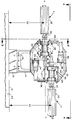
도 1 내지 도 3을 참조하면, 바닥면(12)에 설치되고 볼트(16) 또는 다른 적당한 파스너(fastener)에 의해 터릿 지지 하우징(14)에 고정된 베이스(10)가 도시되어 있다. 필로형 베어링(pillow block)은 터릿 구동 샤프트(20)를 지지하기 위한 베어링이 제공된 하우징(14)에 설치된다. 터릿(22)은 샤프트(20)의 일 단부에 설치되어 있으며 터릿 지지 플레이트(24)를 포함한다.1 to 3, a
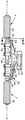
도 1 및 도 4를 참조하면 제 1 드럼(26)은 터릿 지지 플레이트(24)에 회전 가능하게 설치되며 제 1 위치(X)에서 축(A-A)을 중심으로 회전하도록 터릿(22)의 제 1 측면(28)으로부터 외측으로 연장한다. 제 1 드럼(26)은 또한 종동 드럼으로 공지되어 있으며 지지 플레이트(24)상에 설치된 종동 베어링(32) 내에 회전 가능하게 지지된 종동 샤프트(30)상에 설치되어 있다. 또한, 종동 드럼 구동 모터(34)는 지지 플레이트(24)에 설치되어 있으며, 종동 샤프트(30) 및 종동 드럼 구동 모터(34)의 샤프트에 장착되는 풀리 둘레로 연장하는 종동 벨트(36)를 통하여 구동 샤프트(30)와 구동 관계에 있다.1 and 4, the
터릿(22)의 제 2 측면(38)에 설치된 제 2 타이어 성형 드럼(40)은 제 2 위치(Y)에 있는 제 2 축(B-B)을 중심으로 회전 가능하다. 또한 주 드럼으로 공지된 제 2 타이어 성형 드럼(40)은 지지 플레이트(24)상에 설치된 주 베어링(44)에 지지되는 주 샤프트(42)에 설치되어 있다. 주 샤프트는, 지지 플레이트(24)에 설치되고 또 구동 풀리를 거쳐 주 벨트(48)에 의해 주 샤프트와 연결되는 주 드럼 구동 모터(46)에 의해서 구동된다.The second
도 1에 도시된 바와 같이 제 1 드럼(26)의 축(A-A)과 제 2 드럼(40)의 축(B-B)은 평행한 관계에 있으며, 작동 위치에 있어 제 1 드럼(26)은 바닥면(12)으로부터 약 40인치(101.6㎝)인 제 1 높이(50)에 위치하며 이는 바닥면으로부터 약 50인치(127㎝)인 제 2 높이(52)에 위치한 제 2 드럼(40)보다 낮다. 이것은, 타이어 구성요소를 드럼(26)에 장착하기 위한 수작업이 필요할 때 작업자가 드럼에 접근할 수 있도록 드럼(26, 40)이 바닥면(12)에 근접해야 하기 때문에 중요하다.As shown in FIG. 1, the axis AA of the
축(A-A, B-B)이 평행한 것 이외에, 터릿 구조체는 주 샤프트(42)로부터 종동 샤프트(30)가 편향되며, 이에 의해 제 1 드럼(26) 및 제 2 드럼(24)이 터릿의 제 1 측면(28) 및 제 2 측면(38)으로부터 외측으로 연장하는 길이가 최소화된다. 이러한 구조체는 터릿(22)의 회전에 필요한 공간 및 터릿 구동 샤프트(20)의 축을 중심으로 터릿이 회전하는데 필요한 피트(pit)(54)의 깊이를 감소시킨다.In addition to the parallel axes AA, BB, the turret structure is biased by the driven
본 발명의 2개 드럼 터릿 조립체의 효과적인 작동을 위해 제 1 드럼(26) 및 제 2 드럼(40)이 터릿 구동 샤프트(20)의 축(C-C)에 대해 대칭인 축(A-A, B-B)을 갖는 것이 중요하다. 본 발명에 따라서 주 베어링(44)은 소정의 위치에서 지지 플레이트(24)에 설치되어 있다. 이것은, 플레이트에 끼워진 조정 나사(57)로 주 베어링(44)의 에지를 플레이트(24)상의 레지스터(55, 56)에 가압함으로써 이루어진다. 그런 후, 제 1 드럼(26)의 축(A-A)이 터릿 구동 샤프트(20)의 축(C-C)에 대해 대칭적일뿐 아니라 제 2 드럼(40)의 축(B-B)과 평행하도록, 종동 베어링(32)의 위치가 플레이트(24)상에 나사 결합된 조정 나사(58, 59)에 의해서 조정된다. 드럼이 특정한 위치에 있는 것에 관계없이, 드럼에 부착된 타이어 구성요소가 동일 위치에 부착되도록, 이러한 조정에 의해서 제 1 드럼(26) 및 제 2 드럼(40)은 제 1 위치(X) 및 제 2 위치(Y)에 있을 때 동일한 위치에 위치하게 될 것이다.For effective operation of the two drum turret assembly of the present invention the
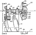
도 2 및 도 3을 참조하면 구동 기어(60)는 터릿 구동 샤프트(20)의 후단부에 설치되어 있다. 구동 기어(60)는 하우징(14)에 설치된 터릿 구동 모터(63)에 의해 구동되는 피니언(pinion) 기어(62)에 의해 맞물리는 반원형 기어 래크(rack)(61)를 갖는다. 도 3에 있어서, 구동 기어(60)가 도 3에 도시된 위치로부터 시계 방향으로 180°회전하고, 그에 따라 도 1에 도시된 터릿 지지 플레이트(24)가 반시계 방향으로 180°회전하여, 제 1 드럼(26)을 도 1에 도시된 제 1 위치(X)에서 도 1에 도시된 제 2 위치(Y)까지 이동시키고 그리고 제 2 드럼(40)을 도 1에 도시된 제 2 위치(Y)에서 도 1에 도시된 제 1 위치(X)까지 이동시킨다. 2개의 작동 위치(X, Y)에 있어서 터릿을 작동 위치에서 로킹하기 위해, 공압 록(pneumatic lock)(66)에 의해 작동되는 캠 롤러(64)는 터릿(22)의 작동 위치에서 테이퍼진 슬롯(68, 70) 내부로 연장한다.2 and 3, the
모터(63)가 정지하는 경우에도, 공압 록(66)에 의해 캠 롤러(64)의 작동을 허용하도록, 반원형 기어 래크(61)의 길이는, 피니언(60)을 분리시키기 위해 미리 결정되며, 그 때 샤프트(20)는 회전을 계속하며 샤프트에 설치되어 그로부터 외측으로 연장하는 아암(72)은 하우징(14)에 설치된 완충 장치(74)와 결합하도록 위치한다. 완충장치(74) 중 하나는, 어떤 방향에 있어서도 아암(72)과의 결합에 의해 터릿 지지 플레이트(24)의 회전을 제한하도록 하우징(14)의 양 측면에 제공된다.Even when the
전형적인 타이어 성형 과정에 있어서, 모터에 연결된 적당한 제어장치에 응답하여 종동 드럼 구동 모터(34) 및 주 드럼 구동 모터(36)의 동작에 의해 드럼을 회전시킴으로써, 타이어 구성요소들은 제 1 드럼(26) 및 제 2 드럼(40)에 장착된다. 타이어 구성요소의 장착 후에 캠 롤러(64)는 해제되며, 터릿 구동 모터(63)는 터릿(22)을 180°회전시키기 위해 적당한 제어에 응답하여 작동하며, 여기서 제 1 드럼(26)은 도 1에 도시된 바와 같은 제 2 위치(Y)로 이동하며 제 2 드럼(40)은 제 1 위치(X)로 이동한다. 제 2 높이(52)의 제 2 위치(Y)에서 제 1 드럼(26)상에 추가의 타이어 구성요소의 장착과 동시에, 타이어 구성요소들은 도 1에 도시된 바와 같은 제 1 위치(X)에서 제 2 타이어 성형 드럼(40)에 장착될 수도 있다. 제 1 드럼(26) 및 제 2 드럼(40)은 동일하나 다른 크기 및 형태의 드럼으로 대체될 수 있으며 이러한 드럼들은 다른 타이어 성형 과정에 적용될 수 있다.In a typical tire shaping process, the tire components are rotated by the operation of the driven
본 발명을 상술하기 위해 대표적인 실시예 및 상세한 설명이 이루어졌으며, 종래 기술에 숙련된 사람들에게 공지된 바와 같이 본 발명의 범위를 벗어남이 없이 다양한 변화 및 변형이 이루어질 수 있다.Representative examples and detailed descriptions have been made to detail the invention, and various changes and modifications may be made without departing from the scope of the invention as is known to those skilled in the art.
본 발명은 동축이 아닌 평행한 축에 대해 회전하는 드럼을 가지는 2개 드럼 터릿으로서 2개 드럼사이에 최소한의 샤프트 길이 및 최소한의 무게를 제공한다.The present invention is a two drum turret having drums rotating about parallel axes rather than coaxial, providing a minimum shaft length and minimum weight between the two drums.
도 1은 본 발명을 실시한 2개 드럼 터릿 조립체의 정면도,1 is a front view of two drum turret assemblies incorporating the present invention;
도 2는 도 1의 2-2선을 따라 취한 드럼이 제거된 터릿 조립체의 측단면도,2 is a side cross-sectional view of the turret assembly with the drum taken along line 2-2 of FIG. 1;
도 3은 도 2의 3-3선을 따라 취한 일부가 절결된 터릿 조립체의 배면도,3 is a rear view of the turret assembly with a portion taken along the line 3-3 of FIG. 2;
도 4는 도 1의 4-4선을 따라 취한 터릿의 부분 평면도.4 is a partial plan view of the turret taken along line 4-4 of FIG.
도면의 주요부분에 대한 부호의 설명Explanation of symbols for main parts of the drawings
20 : 터릿 구동 샤프트 26, 40 : 드럼20: turret drive
32, 44 : 베어링 34, 46 : 드럼 구동 모터32, 44:
60 : 구동 기어 63 : 모터60: drive gear 63: motor
66 : 압축 공기 제륜 장치66: compressed air wheel drive
Claims (5)
Applications Claiming Priority (2)
| Application Number | Priority Date | Filing Date | Title |
|---|---|---|---|
| US08/622,087 | 1996-03-26 | ||
| US08/622,087 US5730829A (en) | 1996-03-26 | 1996-03-26 | Two drum turret for tire assembly |
Publications (2)
| Publication Number | Publication Date |
|---|---|
| KR970064889A KR970064889A (en) | 1997-10-13 |
| KR100500813B1 true KR100500813B1 (en) | 2005-09-26 |
Family
ID=24492893
Family Applications (1)
| Application Number | Title | Priority Date | Filing Date |
|---|---|---|---|
| KR1019970010350A KR100500813B1 (en) | 1996-03-26 | 1997-03-25 | Two drum turret for tire assembly |
Country Status (16)
| Country | Link |
|---|---|
| US (1) | US5730829A (en) |
| EP (1) | EP0798104B1 (en) |
| JP (1) | JP4053625B2 (en) |
| KR (1) | KR100500813B1 (en) |
| CN (1) | CN1072139C (en) |
| AT (1) | ATE218096T1 (en) |
| AU (1) | AU711373B2 (en) |
| BR (1) | BR9701472A (en) |
| CA (1) | CA2197938C (en) |
| CZ (1) | CZ296214B6 (en) |
| DE (1) | DE69712822T2 (en) |
| HU (1) | HUP9700646A1 (en) |
| ID (1) | ID16387A (en) |
| MY (1) | MY120114A (en) |
| PL (1) | PL182709B1 (en) |
| ZA (1) | ZA972401B (en) |
Families Citing this family (12)
| Publication number | Priority date | Publication date | Assignee | Title |
|---|---|---|---|---|
| NL1002306C2 (en) * | 1996-02-12 | 1997-08-13 | Vmi Epe Holland | Assembly of devices for building a green tire for vehicles. |
| US6401783B1 (en) * | 2000-04-12 | 2002-06-11 | The Goodyear Tire & Rubber Company | Two drum turret for tire building |
| WO2003061954A1 (en) * | 2001-12-27 | 2003-07-31 | Gian Luigi Bosio | Tyre building apparatus |
| DE10353629A1 (en) * | 2003-11-17 | 2005-06-16 | Lts Lohmann Therapie-Systeme Ag | Device for the transdermal administration of active substances |
| ITTO20060112A1 (en) * | 2006-02-17 | 2007-08-18 | Marangoni Meccanica | CENTRAL-LINE DRUM FOR PNEUMATIC PACKAGING |
| WO2012003823A1 (en) * | 2010-06-17 | 2012-01-12 | Harburg-Freudenberger Maschinenbau Gmbh | Method and device for producing green tires |
| US20140027063A1 (en) * | 2012-07-25 | 2014-01-30 | Frederic Marie Bernard Marechal | Tire building machine with extendable drums |
| US20150041067A1 (en) * | 2013-08-07 | 2015-02-12 | The Goodyear Tire & Rubber Company | Component applying/cutting apparatus for a tire building machine |
| DE102014015490A1 (en) * | 2014-10-14 | 2016-04-14 | Harburg-Freudenberger Maschinenbau Gmbh | Apparatus and process for the production of green tires |
| IT201600119949A1 (en) | 2016-11-28 | 2018-05-28 | Intereuropean Srl | APPARATUS AND METHOD FOR THE PRODUCTION OF TIRES |
| KR101993274B1 (en) | 2018-04-27 | 2019-09-30 | 김성영 | Tire Manufacturing Apparatus and Manufacturing Method thereof |
| KR102114478B1 (en) | 2018-06-29 | 2020-06-17 | 김성영 | Tire Manufacturing Apparatus and Manufacturing Method thereof |
Citations (1)
| Publication number | Priority date | Publication date | Assignee | Title |
|---|---|---|---|---|
| US4105487A (en) * | 1975-12-27 | 1978-08-08 | Bridgestone Tire Company Limited | Process of and an apparatus for producing green tires |
Family Cites Families (13)
| Publication number | Priority date | Publication date | Assignee | Title |
|---|---|---|---|---|
| US3717529A (en) * | 1971-03-01 | 1973-02-20 | Amf Inc | Application assembly for tread building apparatus |
| US3775220A (en) * | 1971-03-01 | 1973-11-27 | Amf Inc | Apparatus for building tires |
| JPS5143070B2 (en) * | 1972-05-31 | 1976-11-19 | ||
| SU504674A1 (en) * | 1974-04-16 | 1977-03-05 | Предприятие П/Я В-8749 | Pneumatic Tire Assembly Machine |
| US4134783A (en) * | 1976-06-16 | 1979-01-16 | The Goodyear Tire & Rubber Company | Tire building system |
| SU682389A1 (en) * | 1977-04-14 | 1979-08-30 | Ю. И. Кармацкий и В. П. Л\итькин | Apparatus for assembly of radial tyre covers |
| US4197155A (en) * | 1978-08-04 | 1980-04-08 | The Goodyear Tire & Rubber Company | Tire building drum having three orthogonally oriented tire building drums |
| IT1189648B (en) * | 1986-04-08 | 1988-02-04 | Firestone Int Dev Spa | DOUBLE SWIVEL DRUM UNIT FOR THE PRODUCTION OF TIRES |
| JPH02147231A (en) * | 1988-11-29 | 1990-06-06 | Yokohama Rubber Co Ltd:The | Method for molding tire and apparatus thereof |
| JPH03114737A (en) * | 1990-09-04 | 1991-05-15 | Toyo Tire & Rubber Co Ltd | Method of molding automobile tire and apparatus therefor |
| US5031478A (en) * | 1990-10-12 | 1991-07-16 | The Goodyear Tire & Rubber Company | Two gear, connecting arm and crank apparatus |
| JP2655969B2 (en) * | 1992-06-01 | 1997-09-24 | 三菱重工業株式会社 | Tire building equipment |
| JP3187954B2 (en) * | 1992-07-21 | 2001-07-16 | 三菱重工業株式会社 | Tire building system |
-
1996
- 1996-03-26 US US08/622,087 patent/US5730829A/en not_active Expired - Fee Related
-
1997
- 1997-02-19 CA CA002197938A patent/CA2197938C/en not_active Expired - Fee Related
- 1997-03-18 AT AT97104577T patent/ATE218096T1/en active
- 1997-03-18 EP EP97104577A patent/EP0798104B1/en not_active Expired - Lifetime
- 1997-03-18 DE DE69712822T patent/DE69712822T2/en not_active Expired - Fee Related
- 1997-03-19 ZA ZA9702401A patent/ZA972401B/en unknown
- 1997-03-20 MY MYPI97001173A patent/MY120114A/en unknown
- 1997-03-24 ID IDP970958A patent/ID16387A/en unknown
- 1997-03-24 AU AU16474/97A patent/AU711373B2/en not_active Ceased
- 1997-03-25 KR KR1019970010350A patent/KR100500813B1/en not_active IP Right Cessation
- 1997-03-25 BR BR9701472A patent/BR9701472A/en not_active IP Right Cessation
- 1997-03-25 HU HU9700646A patent/HUP9700646A1/en unknown
- 1997-03-26 PL PL97319173A patent/PL182709B1/en not_active IP Right Cessation
- 1997-03-26 JP JP07324797A patent/JP4053625B2/en not_active Expired - Fee Related
- 1997-03-26 CZ CZ0091697A patent/CZ296214B6/en not_active IP Right Cessation
- 1997-03-26 CN CN97104915A patent/CN1072139C/en not_active Expired - Fee Related
Patent Citations (1)
| Publication number | Priority date | Publication date | Assignee | Title |
|---|---|---|---|---|
| US4105487A (en) * | 1975-12-27 | 1978-08-08 | Bridgestone Tire Company Limited | Process of and an apparatus for producing green tires |
Also Published As
| Publication number | Publication date |
|---|---|
| AU711373B2 (en) | 1999-10-14 |
| JP4053625B2 (en) | 2008-02-27 |
| CN1163836A (en) | 1997-11-05 |
| ATE218096T1 (en) | 2002-06-15 |
| DE69712822D1 (en) | 2002-07-04 |
| CN1072139C (en) | 2001-10-03 |
| HUP9700646A1 (en) | 1997-11-28 |
| DE69712822T2 (en) | 2002-11-28 |
| CZ296214B6 (en) | 2006-02-15 |
| KR970064889A (en) | 1997-10-13 |
| US5730829A (en) | 1998-03-24 |
| HU9700646D0 (en) | 1997-05-28 |
| CA2197938A1 (en) | 1997-09-27 |
| PL182709B1 (en) | 2002-02-28 |
| ZA972401B (en) | 1997-09-25 |
| MY120114A (en) | 2005-09-30 |
| AU1647497A (en) | 1997-10-02 |
| CZ91697A3 (en) | 1997-10-15 |
| MX9702027A (en) | 1997-09-30 |
| EP0798104B1 (en) | 2002-05-29 |
| EP0798104A2 (en) | 1997-10-01 |
| BR9701472A (en) | 1998-11-10 |
| ID16387A (en) | 1997-09-25 |
| EP0798104A3 (en) | 1998-02-11 |
| JPH1016083A (en) | 1998-01-20 |
| CA2197938C (en) | 2005-06-21 |
| PL319173A1 (en) | 1997-09-29 |
Similar Documents
| Publication | Publication Date | Title |
|---|---|---|
| KR100500813B1 (en) | Two drum turret for tire assembly | |
| DE59003350D1 (en) | Manipulator for forging machines, especially multi-ram forging machines. | |
| US4434584A (en) | Turret belt grinder | |
| JP3416258B2 (en) | Machine for attaching tires to wheel rims | |
| JP3324668B2 (en) | Belt tension adjustment mechanism for belt drive | |
| US5961379A (en) | Tool grinding machine | |
| EP1145833B1 (en) | Two drum turret for tire building | |
| JPS6035584Y2 (en) | Casing for surrounding the grinding position of a centerless grinder | |
| JP2690959B2 (en) | Spindle device of machine tool | |
| US4760669A (en) | Machine for grinding the brake discs of motor-vehicles | |
| JPS63154301A (en) | Edge processing equipment for tabular work | |
| JPS61188013A (en) | Milling machine for machining crankshaft, etc. | |
| CN220295934U (en) | Accurate trompil mechanism | |
| SU1549740A1 (en) | Arrangement for working brake rims of mine hoists | |
| SU1738611A1 (en) | Device for cleaning shell edges | |
| JPH0752006A (en) | Rotary grinding machine | |
| JPH021310Y2 (en) | ||
| JPS6125954Y2 (en) | ||
| US6949009B1 (en) | Rotating kiln tire refinishing machine | |
| JP2005001047A (en) | Grinding device | |
| JPH0248189Y2 (en) | ||
| SU1085746A1 (en) | Supporting and rotating device | |
| JP2000015343A (en) | Device for holding metallic plate under working | |
| KR0131895Y1 (en) | Backlash control device of automatic pallet exchange device in gear driving part | |
| JPH10166345A (en) | Bolt fastening/unfastening device for shuttering for molding concrete product |
Legal Events
| Date | Code | Title | Description |
|---|---|---|---|
| A201 | Request for examination | ||
| E902 | Notification of reason for refusal | ||
| E701 | Decision to grant or registration of patent right | ||
| GRNT | Written decision to grant | ||
| LAPS | Lapse due to unpaid annual fee |