KR100498623B1 - Information recording device - Google Patents
Information recording device Download PDFInfo
- Publication number
- KR100498623B1 KR100498623B1 KR1019970069751A KR19970069751A KR100498623B1 KR 100498623 B1 KR100498623 B1 KR 100498623B1 KR 1019970069751 A KR1019970069751 A KR 1019970069751A KR 19970069751 A KR19970069751 A KR 19970069751A KR 100498623 B1 KR100498623 B1 KR 100498623B1
- Authority
- KR
- South Korea
- Prior art keywords
- recording
- mark
- period
- length
- level
- Prior art date
Links
Images


Classifications
-
- G—PHYSICS
- G11—INFORMATION STORAGE
- G11B—INFORMATION STORAGE BASED ON RELATIVE MOVEMENT BETWEEN RECORD CARRIER AND TRANSDUCER
- G11B7/00—Recording or reproducing by optical means, e.g. recording using a thermal beam of optical radiation by modifying optical properties or the physical structure, reproducing using an optical beam at lower power by sensing optical properties; Record carriers therefor
- G11B7/004—Recording, reproducing or erasing methods; Read, write or erase circuits therefor
- G11B7/0045—Recording
- G11B7/00452—Recording involving bubble or bump forming
-
- G—PHYSICS
- G11—INFORMATION STORAGE
- G11B—INFORMATION STORAGE BASED ON RELATIVE MOVEMENT BETWEEN RECORD CARRIER AND TRANSDUCER
- G11B7/00—Recording or reproducing by optical means, e.g. recording using a thermal beam of optical radiation by modifying optical properties or the physical structure, reproducing using an optical beam at lower power by sensing optical properties; Record carriers therefor
- G11B7/004—Recording, reproducing or erasing methods; Read, write or erase circuits therefor
- G11B7/0045—Recording
- G11B7/00456—Recording strategies, e.g. pulse sequences
-
- G—PHYSICS
- G11—INFORMATION STORAGE
- G11B—INFORMATION STORAGE BASED ON RELATIVE MOVEMENT BETWEEN RECORD CARRIER AND TRANSDUCER
- G11B11/00—Recording on or reproducing from the same record carrier wherein for these two operations the methods are covered by different main groups of groups G11B3/00 - G11B7/00 or by different subgroups of group G11B9/00; Record carriers therefor
- G11B11/10—Recording on or reproducing from the same record carrier wherein for these two operations the methods are covered by different main groups of groups G11B3/00 - G11B7/00 or by different subgroups of group G11B9/00; Record carriers therefor using recording by magnetic means or other means for magnetisation or demagnetisation of a record carrier, e.g. light induced spin magnetisation; Demagnetisation by thermal or stress means in the presence or not of an orienting magnetic field
- G11B11/105—Recording on or reproducing from the same record carrier wherein for these two operations the methods are covered by different main groups of groups G11B3/00 - G11B7/00 or by different subgroups of group G11B9/00; Record carriers therefor using recording by magnetic means or other means for magnetisation or demagnetisation of a record carrier, e.g. light induced spin magnetisation; Demagnetisation by thermal or stress means in the presence or not of an orienting magnetic field using a beam of light or a magnetic field for recording by change of magnetisation and a beam of light for reproducing, i.e. magneto-optical, e.g. light-induced thermomagnetic recording, spin magnetisation recording, Kerr or Faraday effect reproducing
- G11B11/10502—Recording on or reproducing from the same record carrier wherein for these two operations the methods are covered by different main groups of groups G11B3/00 - G11B7/00 or by different subgroups of group G11B9/00; Record carriers therefor using recording by magnetic means or other means for magnetisation or demagnetisation of a record carrier, e.g. light induced spin magnetisation; Demagnetisation by thermal or stress means in the presence or not of an orienting magnetic field using a beam of light or a magnetic field for recording by change of magnetisation and a beam of light for reproducing, i.e. magneto-optical, e.g. light-induced thermomagnetic recording, spin magnetisation recording, Kerr or Faraday effect reproducing characterised by the transducing operation to be executed
- G11B11/1053—Recording on or reproducing from the same record carrier wherein for these two operations the methods are covered by different main groups of groups G11B3/00 - G11B7/00 or by different subgroups of group G11B9/00; Record carriers therefor using recording by magnetic means or other means for magnetisation or demagnetisation of a record carrier, e.g. light induced spin magnetisation; Demagnetisation by thermal or stress means in the presence or not of an orienting magnetic field using a beam of light or a magnetic field for recording by change of magnetisation and a beam of light for reproducing, i.e. magneto-optical, e.g. light-induced thermomagnetic recording, spin magnetisation recording, Kerr or Faraday effect reproducing characterised by the transducing operation to be executed to compensate for the magnetic domain drift or time shift
-
- G—PHYSICS
- G11—INFORMATION STORAGE
- G11B—INFORMATION STORAGE BASED ON RELATIVE MOVEMENT BETWEEN RECORD CARRIER AND TRANSDUCER
- G11B11/00—Recording on or reproducing from the same record carrier wherein for these two operations the methods are covered by different main groups of groups G11B3/00 - G11B7/00 or by different subgroups of group G11B9/00; Record carriers therefor
- G11B11/10—Recording on or reproducing from the same record carrier wherein for these two operations the methods are covered by different main groups of groups G11B3/00 - G11B7/00 or by different subgroups of group G11B9/00; Record carriers therefor using recording by magnetic means or other means for magnetisation or demagnetisation of a record carrier, e.g. light induced spin magnetisation; Demagnetisation by thermal or stress means in the presence or not of an orienting magnetic field
- G11B11/105—Recording on or reproducing from the same record carrier wherein for these two operations the methods are covered by different main groups of groups G11B3/00 - G11B7/00 or by different subgroups of group G11B9/00; Record carriers therefor using recording by magnetic means or other means for magnetisation or demagnetisation of a record carrier, e.g. light induced spin magnetisation; Demagnetisation by thermal or stress means in the presence or not of an orienting magnetic field using a beam of light or a magnetic field for recording by change of magnetisation and a beam of light for reproducing, i.e. magneto-optical, e.g. light-induced thermomagnetic recording, spin magnetisation recording, Kerr or Faraday effect reproducing
- G11B11/10595—Control of operating function
-
- G—PHYSICS
- G11—INFORMATION STORAGE
- G11B—INFORMATION STORAGE BASED ON RELATIVE MOVEMENT BETWEEN RECORD CARRIER AND TRANSDUCER
- G11B7/00—Recording or reproducing by optical means, e.g. recording using a thermal beam of optical radiation by modifying optical properties or the physical structure, reproducing using an optical beam at lower power by sensing optical properties; Record carriers therefor
- G11B7/004—Recording, reproducing or erasing methods; Read, write or erase circuits therefor
- G11B7/0045—Recording
- G11B7/00454—Recording involving phase-change effects
-
- G—PHYSICS
- G11—INFORMATION STORAGE
- G11B—INFORMATION STORAGE BASED ON RELATIVE MOVEMENT BETWEEN RECORD CARRIER AND TRANSDUCER
- G11B7/00—Recording or reproducing by optical means, e.g. recording using a thermal beam of optical radiation by modifying optical properties or the physical structure, reproducing using an optical beam at lower power by sensing optical properties; Record carriers therefor
- G11B7/007—Arrangement of the information on the record carrier, e.g. form of tracks, actual track shape, e.g. wobbled, or cross-section, e.g. v-shaped; Sequential information structures, e.g. sectoring or header formats within a track
-
- G—PHYSICS
- G11—INFORMATION STORAGE
- G11B—INFORMATION STORAGE BASED ON RELATIVE MOVEMENT BETWEEN RECORD CARRIER AND TRANSDUCER
- G11B7/00—Recording or reproducing by optical means, e.g. recording using a thermal beam of optical radiation by modifying optical properties or the physical structure, reproducing using an optical beam at lower power by sensing optical properties; Record carriers therefor
- G11B7/12—Heads, e.g. forming of the optical beam spot or modulation of the optical beam
- G11B7/125—Optical beam sources therefor, e.g. laser control circuitry specially adapted for optical storage devices; Modulators, e.g. means for controlling the size or intensity of optical spots or optical traces
- G11B7/126—Circuits, methods or arrangements for laser control or stabilisation
-
- G—PHYSICS
- G11—INFORMATION STORAGE
- G11B—INFORMATION STORAGE BASED ON RELATIVE MOVEMENT BETWEEN RECORD CARRIER AND TRANSDUCER
- G11B7/00—Recording or reproducing by optical means, e.g. recording using a thermal beam of optical radiation by modifying optical properties or the physical structure, reproducing using an optical beam at lower power by sensing optical properties; Record carriers therefor
- G11B7/12—Heads, e.g. forming of the optical beam spot or modulation of the optical beam
- G11B7/125—Optical beam sources therefor, e.g. laser control circuitry specially adapted for optical storage devices; Modulators, e.g. means for controlling the size or intensity of optical spots or optical traces
- G11B7/127—Lasers; Multiple laser arrays
- G11B7/1275—Two or more lasers having different wavelengths
-
- G—PHYSICS
- G11—INFORMATION STORAGE
- G11B—INFORMATION STORAGE BASED ON RELATIVE MOVEMENT BETWEEN RECORD CARRIER AND TRANSDUCER
- G11B7/00—Recording or reproducing by optical means, e.g. recording using a thermal beam of optical radiation by modifying optical properties or the physical structure, reproducing using an optical beam at lower power by sensing optical properties; Record carriers therefor
- G11B7/004—Recording, reproducing or erasing methods; Read, write or erase circuits therefor
- G11B7/0055—Erasing
- G11B7/00557—Erasing involving phase-change media
-
- G—PHYSICS
- G11—INFORMATION STORAGE
- G11B—INFORMATION STORAGE BASED ON RELATIVE MOVEMENT BETWEEN RECORD CARRIER AND TRANSDUCER
- G11B7/00—Recording or reproducing by optical means, e.g. recording using a thermal beam of optical radiation by modifying optical properties or the physical structure, reproducing using an optical beam at lower power by sensing optical properties; Record carriers therefor
- G11B7/004—Recording, reproducing or erasing methods; Read, write or erase circuits therefor
- G11B7/006—Overwriting
Abstract
기록매체에 에너지를 조사하는 것에 의해서 기록매체에 국소적인 물리적변화를 일으켜 정보의 기록을 실행하는 정보기록장치에 관한 것으로서, 열크로스토크의 억제 및 열축적의 일정화를 실현하기 의해, 기록매체에 에너지를 조사하는 것에 의해서 매체에 국소적인 물리적변화를 일으켜 데이타를 기록하는 정보기록장치에 있어서, 데이타 기록시의 기록부호열에 있어서의 마크의 마크길이를 변별하는 마크길이 변별수단 및 기록부호열에 있어서의 동일 길이의 후속스페이스의 기록시에 마크길이 변별수단의 변별결과에 따라서 적어도 2종류의 기록파형을 발생하는 기록에너지 조사수단을 포함하고, 기록파형은 적어도 2개의 에너지레벨로 이루어지는 마크형성기간과 적어도 2개의 에너지레벨로 이루어지는 마크비형성기간을 포함하는 구성으로 하였다.An information recording apparatus for recording information by causing local physical changes to a recording medium by irradiating energy to the recording medium. The present invention relates to an information recording apparatus by suppressing thermal crosstalk and realizing constant heat accumulation. An information recording apparatus for recording data by causing a local physical change on a medium by irradiating energy, wherein the mark length discriminating means for discriminating the mark length of the mark in the recording code string at the time of data recording and the recording code string Recording energy investigating means for generating at least two types of recording waveforms in accordance with the discrimination result of the mark length discriminating means when recording subsequent spaces of the same length, wherein the recording waveforms include at least a mark forming period comprising at least two energy levels; The configuration including the mark non-forming period consisting of two energy levels It was.
이와 같이 하는 것에 의해, 기록/재생동작의 고신뢰화가 도모되고 동시에 정보기록장치 및 기록매체의 소형화가 실현되므로 비용의 점에서 유리하게 된다는 효과가 얻어진다.By doing so, high reliability of the recording / reproducing operation can be achieved, and at the same time, the miniaturization of the information recording apparatus and the recording medium can be realized, so that the effect of cost is obtained.
Description
본 발명은 기록매체에 에너지를 조사하는 것에 의해서 기록매체에 국소적인 물리적변화를 일으켜 정보의 기록을 실행하는 정보기록장치에 관한 것으로서, 전적으로 광디스크장치에 관한 것이다.BACKGROUND OF THE INVENTION 1. Field of the Invention [0001] The present invention relates to an information recording apparatus for recording information by causing local physical change to the recording medium by irradiating energy to the recording medium. The present invention relates entirely to an optical disc apparatus.
현재, 일반적으로 유통되고 있는 광디스크는 기록막을 가열하는 것에 의해 기록막상에 반전자구에 의한 마크를 형성하는 광자기디스크와 가열시의 에너지투입량을 제어하는 것에 의해 기록막의 냉각속도를 변화시키고 기록막상에 비정질화영역에 의한 마크를 형성하는 상변화디스크로 크게 나눌 수 있다. 이들 광디스크에 있어서 기록밀도향상을 도모하기 위한 방법으로서는 정보를 담당하는 마크를 전체적으로 축소하거나 마크길이, 스페이스길이의 변화의 간격을 짧게 해서 마크에지 위치를 검출하는 시간폭을 좁게 취하는 방법을 들 수 있지만, 어떠한 방식에 있어서도 마크를 고정밀도로 형성하는 것이 필수이다. 그러나, 광스폿직경의 약 1/2 이하의 미소마크를 안정하고 또한 고정밀도로 형성하는 것은 매우 어렵다. 이것은 미소마크를 형성하는 경우에는 광스폿에 의한 기록막의 승온부분 중에서도 피크 온도부분 부근의 공간적인 온도구배가 완만한 부분에서만 마크 형성을 하지 않으면 안되기 때문이다. 이 때문에 기록에너지 조사전의 기록막온도나 기록에너지의 강도변동에 의해서 기록시의 최고도달온도가 마크마다 변동하고, 실효적으로 기록막의 기록감도가 변동하면 마크형상이 크게 불균일하게 된다. 기록파형에 의해서 마크의 형상을 제어하는 형태의 광디스크인 경우, 특히 기록패턴에 의해서 기록막의 최고도달온도에 편차가 발생하기 쉽다. 이 문제를 해결하기 위해서는 단파장레이저 광원을 사용해서 광스폿 직경을 축소하는 것이 가장 직접적이다. 그러나, 대표적인 레이저광원인 반도체레이저/다이오드의 단파장화는 기록밀도의 상승에 대한 요구에완전히 부응하지 못하고 있는 것이 현상이다.Currently, optical disks generally distributed have changed the cooling rate of the recording film by controlling the energy input amount during heating and the magneto-optical disk forming the mark by the inverted magnetic domain on the recording film by heating the recording film, and on the recording film. It can be roughly divided into phase change discs forming marks by amorphous regions. As a method for improving recording density in these optical discs, there is a method of reducing the time span for detecting the mark edge position by reducing the mark in charge of information as a whole or shortening the interval between changes in mark length and space length. In any manner, it is essential to form the mark with high accuracy. However, it is very difficult to stably and precisely form a micromark of about 1/2 or less of the light spot diameter. This is because in the case of forming a micro mark, the mark must be formed only in a portion where the spatial temperature gradient near the peak temperature portion is gentle among the temperature rising portions of the recording film caused by the light spot. For this reason, when the recording film temperature before recording energy irradiation or the intensity of recording energy fluctuates, the maximum reaching temperature at the time of recording fluctuates for each mark, and if the recording sensitivity of the recording film is effectively changed, the mark shape becomes very uneven. In the case of an optical disc of the type in which the shape of the mark is controlled by the recording waveform, in particular, the recording pattern tends to cause a deviation in the maximum reaching temperature of the recording film. To solve this problem, it is most straightforward to reduce the diameter of the light spot using a short wavelength laser light source. However, shortening the wavelength of a semiconductor laser / diode, which is a typical laser light source, does not fully meet the demand for an increase in recording density.
따라서, 미소마크를 안정하게 형성하고 신뢰성이 높은 기록/재생을 실행하기 위해서는 이들 문제가 거의 발생하지 않는 기록파형을 선택하지 않으면 안된다. 기록파형의 해결해야 할 문제는 다음의 2가지이다. 즉, 제1의 문제는 열크로스토크(crosstalk)의 억제로서, 이것은 근접하는 마크를 그의 간격에 관계없이 균일하게 형성할 수 있는 것을 의미한다. 제2의 문제는 열축적의 일정화로서, 이것은 연속하는 마크를 그의 길이에 관계없이 균일하게 형성할 수 있는 것을 의미한다. 열크로스토크의 억제, 열축적의 일정화를 실현하는 것에 의해 재생신호의 에지시프트를 억제할 수 있으므로, 기록방식으로서 고선밀도화에 유리한 마크에지 기록방식을 사용하는 것이 가능하게 된다. 또, 열축적의 일정화를 실현하는 것에 의해서 재생크로스토크의 일정화를 도모할 수 있고 트랙간격을 축소할 수 있으므로, 결과로서 기록면밀도의 향상이 실현가능하게 된다.Therefore, in order to form micromarks stably and to perform recording / reproducing with high reliability, recording waveforms in which these problems hardly occur must be selected. There are two problems to be solved in the recording waveform. That is, the first problem is the suppression of thermal crosstalk, which means that an adjacent mark can be formed uniformly regardless of its spacing. The second problem is the constant heat accumulation, which means that a continuous mark can be formed uniformly regardless of its length. By suppressing thermal crosstalk and realizing thermal accumulation, the edge shift of the reproduction signal can be suppressed. Thus, it is possible to use a mark edge recording method which is advantageous for high linear density as the recording method. In addition, by realizing the thermal accumulation, the reproduction crosstalk can be constant and the track interval can be reduced. As a result, the recording surface density can be improved.
이상의 문제를 해결할 목적으로 일본국 특허출원 평성5-298737호에 기재된 제1의 종래기술에서는 마크형성기간에 상당하는 기록파형을 기록부호열의 마크길이에 대응한 일련의 펄스열로 구성하고, 각 펄스의 개수 및 진폭을 기록부호열의 길이에 따라서 제어한다. 마크형성기간의 기록파형은 선두부와 후속부분의 2개의 부분으로 나뉘어지고, 각 펄스의 펄스높이는 일반적으로 다르다. 또, 기록파형의 마크비형성기간에는 스페이스부를 전치(前置)해서 기록보조펄스를 발생한다. 마크 형성기간이라는 것은 기록부호열에 있어서의 마크길이를 반영하고, 도 4의 (c)에 도시한 바와 같이 임의의 마크의 형성에 필요한 기록에너지를 공급하는 에너지레벨을 가진 펄스, 즉 이 에너지레벨이 발생되지 않으면 마크가 형성되지 않는 에너지레벨의 펄스의 최초 펄스의 상승부터 최후 펄스의 하강까지로서 정의한다. 또, 마크비형성기간이라는 것은 기록부호열에 있어서의 스페이스의 길이를 반영하고, 마크 형성기간 이외의 기간으로서 정의한다. 이상의 정의는 본 명세서중의 설명에 있어서 공통이다. 이상에 의해 스페이스길이에 관계없이 선행하는 마크형성부분에서 직후 마크의 앞쪽에지위치로의 열확산을 보상할 수 있어 마크폭 및 마크에지위치를 고정밀도로 제어할 수 있는 것으로 하고 있다.In order to solve the above problem, in the first conventional technique described in Japanese Patent Application No. Hei 5-298737, the recording waveform corresponding to the mark forming period is composed of a series of pulse strings corresponding to the mark length of the recording code string, The number and amplitude are controlled according to the length of the recording code string. The recording waveform of the mark formation period is divided into two parts, the leading part and the subsequent part, and the pulse height of each pulse is generally different. In the mark ratio formation period of the recording waveform, the space assisting part is transposed to generate a recording auxiliary pulse. The mark formation period reflects the mark length in the recording code string, and as shown in Fig. 4C, a pulse having an energy level for supplying the recording energy required for forming any mark, that is, the energy level is If it is not generated, it is defined as the rising edge of the first pulse of the pulse of the energy level at which no mark is formed until the falling of the last pulse. The mark non-forming period reflects the length of the space in the recording code string and is defined as a period other than the mark forming period. The above definition is common in the description in this specification. As described above, it is possible to compensate for the thermal diffusion from the preceding mark forming portion immediately to the front edge position of the mark irrespective of the space length, and to control the mark width and the mark edge position with high precision.
또, 상기의 문제를 해결할 목적으로, 일본국 특허공개공보 평성1-078437호에 기재된 제2의 종래기술에서는 선행하는 마크비형성기간의 길이를 참조하여 직후 마크형성기간에 대응하는 기록파형의 일부를 가변으로 하고 있다. 즉, 도 4의 (a)에 있어서, 각각에 선행하는 스페이스(401), (403)의 길이를 참조해서 마크(402), (404)에 대응하는 기록파형, 더욱 상세하게는 마크(402), (404)의 앞쪽에지 형성위치를 보상하는 기록에너지 조사수단을 구비하고 있다. 이것에 의해, 스페이스길이에 관계없이 선행마크형성부분에서 직후 마크의 앞쪽에지위치로의 열확산을 보상할 수 있으며 마크폭 및 마크에지위치를 고정밀도로 제어할 수 있는 것으로 하고 있다.In order to solve the above problem, in the second conventional technique described in Japanese Patent Application Laid-open No. Hei 1-078437, a part of the recording waveform corresponding to the mark forming period immediately after referring to the length of the preceding mark non-forming period is referred to. Is variable. That is, in Fig. 4A, the recording waveforms corresponding to the
또, 다른 공지예로서는 일본국 특허공개공보 평성5-143993호가 있고 그 공보에 있어서는 직전의 라이트펄스와 현재의 라이트펄스 사이의 공백기간이 짧은 경우에는 직전의 광펄스에 의해 발생한 열의 영향을 받으므로 이 예열효과를 공백기간이 긴 경우와 동일하게 한다는 기재 및 직전의 라이트펄스의 펄스폭과 직전의 공백 기간의 측정값을 사용해서 현재의 라이트펄스의 직전에 마련하는 바이어스발광부의 에너지량 및 펄스폭을 결정한다는 기재가 있다.Another known example is Japanese Patent Application Laid-open No. Hei 5-143993. In that publication, when the empty period between the previous light pulse and the current light pulse is short, it is affected by the heat generated by the previous light pulse. The energy amount and pulse width of the bias light emitting unit provided immediately before the current light pulse, using the description that the preheating effect is the same as the case where the empty period is long and the measured pulse width of the immediately preceding light pulse and the measured empty period. There is a description to determine.
그러나, 제1의 문제점으로서 상기의 각 종래기술에서는 후속마크의 앞쪽에지 부분의 형성조건의 보상을 실행하고 있었지만, 이 보상이 충분하지는 않았다. 또, 선행마크형성시에 투입된 에너지량의 대소에 의한 직후 마크의 앞쪽에지형성위치 부근으로의 열확산의 보상은 고려되어 있지 않았으므로 선행마크형성기간이 일정길이인 경우에 한해 2개의 마크간의 마크비형성기간의 길이에 관계없이 후속 마크를 안정하게 기록하는 것이 가능하였다. 그러나, 직전의 마크형성기간이 변화하는 경우에는 2개의 마크간의 마크비형성기간이 일정하더라도 후속 마크의 앞쪽에지를 목표위치에 형성하는 것은 곤란하였다. 즉, 선행마크형성기간이 길수록 선행마크 형성시에 투입된 열에너지가 직후 마크의 앞쪽에지형성위치 부근으로 확산하고 앞쪽에지가 직전의 마크의 뒤쪽에지에 접근한다. 이상의 현상은 기록선밀도를 상승시킨 경우 및 2개의 마크간의 마크비형성기간이 짧을수록 현저하게 된다.However, as the first problem, each of the above prior arts has compensated the formation conditions of the front edge portion of the subsequent mark, but this compensation was not sufficient. In addition, since the compensation for thermal diffusion to the front edge of the mark immediately after the large amount of energy input at the time of forming the preceding mark was not considered, the mark ratio between two marks only when the preceding mark formation period was a certain length. Regardless of the length of the formation period, it was possible to stably record subsequent marks. However, in the case where the immediately preceding mark formation period changes, it is difficult to form the front edge of the subsequent mark at the target position even if the mark ratio formation period between the two marks is constant. In other words, the longer the preceding mark formation period, the more the heat energy introduced during the formation of the preceding mark diffuses immediately near the front edge forming position of the mark, and the front edge approaches the rear edge of the immediately preceding mark. The above phenomenon becomes more remarkable when the recording line density is increased and as the mark ratio forming period between two marks is shorter.
또, 제2의 문제점으로서 상기의 각 종래기술에서는 열축적의 일정화가 불충분하고, 마크폭을 축소하여 기록선밀도를 상승시킨 경우에 마크길이에 의존한 뒤쪽 에지의 목표위치로부터의 변동을 충분히 억제할 수 없었다. 즉, 마크선두부로부터의 거리에 의존해서 뒤쪽에지위치 및 마크폭이 변동하고 있었다. 이상의 현상은 기록선밀도를 상승시킬수록 현저하게 된다.As a second problem, in each of the above conventional techniques, the thermal accumulation is insufficient, and when the mark width is reduced to increase the recording line density, variations from the target position of the rear edge depending on the mark length can be sufficiently suppressed. Could not. In other words, the position of the back edge and the mark width were varied depending on the distance from the head of the mark. The above phenomenon becomes more remarkable as the recording line density is increased.
따라서, 이상의 이유에 의해 상기의 각 종래기술에서는 고기록선밀도시에 미소마크를 충분한 정밀도로 형성하는 것이 불가능하고 결과로서 충분한 기록면밀도를 실현할 수 없었다.Therefore, for the above reasons, in each of the above prior arts, it is impossible to form minute marks with sufficient precision at high recording line densities, and as a result, sufficient recording surface densities cannot be realized.
상기 제1의 문제를 해결할 목적으로, 기록매체에 에너지를 조사하는 것에 의해서 기록매체에 국소적인 물리적변화를 일으켜 정보의 기록을 실행하는 정보기록 장치에 있어서, 기록부호열에 있어서의 동일길이의 마크기록시에 적어도 2종류의 기록파형을 발생하는 기록에너지 조사수단 또는 기록부호열에 있어서의 동일길이의 스페이스기록시에 적어도 2종류의 기록파형을 발생하는 기록에너지 조사수단을 구비한다.In the information recording apparatus for recording information by causing local physical change on the recording medium by irradiating energy to the recording medium for the purpose of solving the first problem, the mark recording of the same length in the recording code string Recording energy irradiation means for generating at least two types of recording waveforms at the time of recording or recording energy irradiation means for generating at least two types of recording waveforms during space recording of the same length in the recording code string.
또, 상기 제1의 문제를 해결할 목적으로, 기록매체에 에너지를 조사하는 것에 의해서 기록매체에 국소적인 물리적변화를 일으켜 정보의 기록을 실행하는 정보기록장치에 있어서, 데이타 기록시의 기록부호열에 있어서의 기록패턴 식별수단을 갖고, 이 기록부호열에 있어서의 동일길이의 마크기록시에 상기 식별수단의 식별결과에 따라서 적어도 2종류의 기록파형을 발생하는 기록에너지 조사수단 또는 이 기록 부호열에 있어서의 동일길이의 스페이스기록시에 상기 식별수단의 식별결과에 따라서 적어도 2종류의 기록파형을 발생하는 기록에너지 조사수단을 구비한다.An information recording apparatus for recording information by causing a local physical change on a recording medium by irradiating energy to the recording medium for the purpose of solving the first problem, wherein the recording code string is used for data recording. Recording energy checking means or the same in the recording code string having at least two types of recording waveforms in accordance with the identification result of the identifying means when recording the same length in the recording code string; And recording energy irradiation means for generating at least two types of recording waveforms in accordance with the identification result of the identification means at the time of space recording of the length.
여기서, 기록패턴이라는 것은 마크 또는 스페이스의 길이 및 그 배열순서관계 등의 정보를 의미하며, 기록파형이라는 것은 기록매체에 조사하는 기록에너지의 부가방법 즉 기록에너지레벨의 시간변화를 의미한다.Here, the recording pattern means information such as the length of a mark or a space and the arrangement order relationship thereof, and the recording waveform means a method of adding recording energy to a recording medium, that is, a time change of the recording energy level.
이상에 의해 직전의 마크와의 사이에 있는 스페이스길이에 관해서 후속마크의 앞쪽에지부분의 형성조건의 보상을 정밀하게 실행하고, 또 직전의 마크의 형성시에 투입된 에너지량의 대소에 의한 직후마크의 앞쪽에지형성위치 부근으로의 열확산의 보상을 실행한다. 이 때문에 직전의 마크의 길이 및 2개의 마크간의 스페이스의 길이에 관계없이 마크를 안정하게 기록하는 것이 가능하게 된다.As a result, the compensation for the formation conditions of the front edge portion of the subsequent mark with respect to the space length between the immediately preceding mark is precisely performed, and the mark immediately after the large or small amount of energy input at the time of forming the immediately preceding mark. Compensation for thermal diffusion near the front edge forming position is performed. Therefore, the mark can be stably recorded regardless of the length of the immediately preceding mark and the length of the space between the two marks.
또, 상기 제2의 문제를 해결할 목적으로, 기록매체에 에너지를 조사하는 것에 의해서 기록매체에 국소적인 물리적변화를 일으켜 정보의 기록을 실행하는 정보기록장치에 있어서, 마크형성기간의 기록파형의 상엔벌로프 및 하엔벌로프가 마크형성 기간 선두로부터의 시간경과에 따라서 저하하는 상기 기록파형을 발생하는 기록에너지 조사수단을 구비한다.An information recording apparatus for recording information by causing local physical change to the recording medium by irradiating energy to the recording medium for the purpose of solving the second problem, wherein the recording waveform in the mark formation period is used. The envelope and the lower envelope are provided with recording energy irradiation means for generating the recording waveform which decreases with the passage of time from the beginning of the mark forming period.
이상에 의해, 긴 마크형성시의 열축적의 보상이 엄밀하게 실행되어 마크길이에 관계없이 길이마크의 뒤쪽에지가 목표로 하는 위치에 정확하게 형성되게 된다.By the above, compensation of thermal accumulation at the time of forming a long mark is performed strictly, and the edge of a length mark is exactly formed in the target position irrespective of mark length.
[발명의 실시예][Examples of the Invention]
이하, 본 발명의 실시예를 설명한다. 본 실시예에서는 기록매체로서 광자기기록매체를 예로 들어 설명하겠지만, 이것은 기록매체를 특히 한정하는 것은 아니고, 기록매체에 에너지를 조사하는 것에 의해서 기록매체에 국소적인 물리적변화를 일으켜 정보의 기록을 실행하는 기록매체에 공통적인 기술이다.Hereinafter, embodiments of the present invention will be described. In this embodiment, a magneto-optical recording medium will be described as an example of the recording medium. However, this does not particularly limit the recording medium, and causes recording of information by causing local physical changes to the recording medium by irradiating energy to the recording medium. This is a common technique for recording media.
또, 이하의 실시예에 있어서는 단일의 파라미터만이 다른 기록파형을 사용해서 설명하겠지만, 이것은 본 발명에 있어서의 기록파형의 조합을 한정하는 것은 아니다. 즉, 예를 들면 도 8의 (a)에 도시한 기록파형은 Pa, Pb. Pw1 Pw2, Tb. Tw1, Tw2, Tbw의 각 파라미터를 지정하면 일의적으로 기술할 수 있지만. 다른 기록파형의 조합으로서 이들 여러개의 파라미터가 동시에 다른 기록파형을 사용해도 좋고, 기록파형의 변화부분은 마크형성부분 또는 마크비형성부분이라도 좋고 이 양자라도 좋다. 또, 기록파형을 기술하는 파라미터를 한정하는 것도 아니고, 본 실시예 이외의 파라미터로 기술되는 기록파형의 조합을 사용해도 좋다. 또, 도 8의 (a), 도 8의 (b)에 도시한 바와 같이, 공통의 파라미터로 기술할 수 없는 기록파형의 조합을 사용해도 당연히 좋다.In the following embodiments, only a single parameter will be described using different recording waveforms, but this does not limit the combination of recording waveforms in the present invention. That is, for example, the recording waveforms shown in Fig. 8A are Pa, Pb. Pw1 Pw2, Tb. Although each parameter of Tw1, Tw2, Tbw can be specified uniquely. As a combination of different recording waveforms, these recording parameters may use different recording waveforms at the same time, and the change portion of the recording waveform may be a mark formation portion or a mark ratio formation portion, or both. Note that a combination of recording waveforms described by parameters other than the present embodiment may be used without limiting the parameters describing the recording waveforms. In addition, as shown in Figs. 8A and 8B, combinations of recording waveforms that cannot be described by common parameters may be used.
또, 기록에너지의 레벨이라는 것은 기록매체상의 기록막의 열적인 완화시간보다 긴 기간에 걸친 평균에너지레벨을 의미하고, 어떠한 이유에 의해 채널비트길이(마크, 스페이스의 에지위치의 변화단위)에 상당하는 주기의 주파수보다 충분히 높은 주파수성분이 기록파형에 중첩되어 있는 경우에는 그 주파수성분의 영향을 무시할 수 있는 정도 이상의 기간에 걸친 평균에너지레벨을 나타내는 것으로 한다.In addition, the recording energy level means an average energy level over a period longer than the thermal relaxation time of the recording film on the recording medium, and for some reason corresponds to the channel bit length (mark, unit of change of the edge position of the space). When a frequency component sufficiently higher than the frequency of the period is superimposed on the recording waveform, it is assumed that the average energy level is over a period of time over which the influence of the frequency component can be ignored.
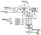
도 1은 본 발명에 의한 정보기록장치의 구성의 1예를 설명하는 도면이다. 기록되는 사용자데이타(115)는 컨트롤러(118)에 의해서 관리되고, 소정량에 도달할때까지 일단 버퍼(114)에 축적된다. 버퍼(114)에서 송출된 기록데이타(127)은 부호기(113)에 있어서 광자기기록매체(117)상에 형성되는 마크(도시하지 않음)배치에 대응하는 기록부호열(126)으로 변환된다. 기록부호열(126)은 기록파형발생회로(112)고 전달되고 여기서 기록파형에 대응한 레벨발생신호(125)로 변환된다. 부호기(113), 기록파형발생회로(112)는 기준시간발생기(119)가 발생하는 기준시간신호(128)과 동기해서 동작한다. 레이저구동회로(111)은 레벨발생신호(125)를 참조해서 레이저구동전류(124)를 발생하고, 기록에너지원인 레이저(110)을 소정의 기록파형에 따라서 발광시킨다. 레이저(110)에서 방출된 레이저광(123)은 하프미러(108), 대물렌즈(116)을 경유해서 광자기기록매체(117)상에 집광되고, 기록막(도시하지 않음)을 가열해서 마크를 형성한다. 정보의 재생시에는 마크를 파괴하지 않을 정도로 낮은 레벨의 레이저광(123)에 의해 광자기 기록매체(117)상의 마크배열을 주사한다. 광자기기록매체(117)로부터의 반사광은 대물렌즈(116), 하프미러(108)을 경유하여 편광분리소자(107)에 입사된다. 편광분리소자(107)에서는 마크의 자화방향에 따라서 편광면이 역방향으로 회전한 반사광을 서로 직교하는 편광으로 분리하고, 각각은 검출렌즈(106)을 통해서 광검출기(101)상으로 보내진다. 광검출기(101)은 서로 직교하는 편광의 강도를 그들과 비례한 전기신호로 변환한다. 이 전기신호는 각각의 광검출기(101)에 마련된 전치증폭기(100)에 의해서 충분한 진폭까지 증폭된 후, 차동증폭기(102)로 전달된다. 차동증폭기(102)는 입력신호간의 차를 연산하여 광자기기록매체(117)상의 주사위치에 있어서의 마크의 유무에 대응한 광자기재생신호(120)을 생성한다. 광자기재생신호(120)은 파형등화기(103)에 의해서 파형등화처리를 받고, 또 2진화기(104)에 있어서 2진화재생신호(121)로 변환된다. 또, 복호기(105)는 이 2진화재생신호(121)을 참조하여 부호기(113)의 역변환을 실시해서 재생데이타(122)를 버퍼(114)에 축적한다. 재생데이타(122)는 컨트롤러(118)에 의해서 관리되고, 소정량에 도달하면 최종적으로 재생된 사용자데이타(115)로서 장치외부로 출력된다.1 is a view for explaining an example of the configuration of an information recording apparatus according to the present invention. The
도 2의 (a)∼(d)는 본 발명에 있어서의 기록부호열의 마크 스페이스와 그것을 기록하는 기록파형의 1예를 설명하는 도면이다. 도 2의 (a)는 기록데이타를 부호기에 의해 변환한 결과의 기록부호열을 도시하고 있다. 도 2의 (b)는 기록매체상의 마크배열의 이미지를 도시한 것으로서, 기록/재생용 레이저광스폿은 도 2의 (b)중 좌측에서 우측으로 주사한다. 마크(202)는 기록부호열(200)중의 각각의 마크에 1대1로 대응하고 있고, 그 기간에 비례한 길이로 형성된다. 도 2의 (c)는 도 2의 (a)의 기록부호열(200)에 대응한 본 발명에 있어서의 기록파형의 1예로서, 기록부호열(200)에 있어서의 2L길이의 마크기록시에 다른 2종류의 기록파형을 발생한다. 또, 도 2의 (d)는 도 2의 (a)의 기록부호열(200)에 대응한 본 발명에 있어서의 기록 파형의 다른 1예로서, 기록부호열(200)에 있어서의 3L길이의 스페이스기록시에 다른 2종류의 기록파형을 발생한다. 여기서, L은 기록부호열(200)에 있어서의 마크길이 및 스페이스길이의 변화량의 최소단위이다.2A to 2D are diagrams for explaining an example of a mark space of a recording code string and a recording waveform for recording the same in the present invention. Fig. 2A shows the recording code string of the result of converting the recording data by the encoder. FIG. 2B shows an image of the mark array on the recording medium, and the recording / reproducing laser light spot is scanned from left to right in FIG. The
도 3은 도 1의 기록처리계(129)의 구성의 1예를 상세하게 설명한 도면이다. 기록데이타(127)은 부호기(113)에 있어서 소정의 변환규칙에 따라 기록부호열(126)으로 변환된다. 기록부호열(126)은 기록패턴인식기(302), 마크길이래치(300) 및 스페이스길이래치(301)에 입력된다. 마크길이래치(300)은 기록부호열(126)중의 마크길이를, 스페이스길이래치(301)은 기록부호열(126)중의 스페이스길이를 선입선출(FIFO) 동작에 의해 소정기간 유지하고, 각각이 유지하는 마크길이, 스페이스길이는 기록패턴인식기(302)에 입력된다. 기록패턴인식기(302)는 부호기(113)으로부터의 기록부호열(126) 및 선행하는 기록패턴의 정보인 마크길이래치(300) 및 스페이스길이래치(301)로부터의 정보를 참조하여 실제의 기록파형에 대응한 Pb발생신호(311). Pa발생신호(312), Pw1발생신호(313), Pw2발생신호(314)를 선행하는 기록패턴에 따라서 적응적으로 발생한다. 레이저구동회로(111)은 이들 레벨발생신호(125)를 참조해서 레이저구동전류(124)를 합성하고, 기록에너지원인 레이저(110)을 구동한다. 또, 부호기(113), 기록패턴인식기(302), 마크길이래치(300) 및 스페이스길이래치(301)은 기준시간신호(128)에 의해서 제어되고 있고, 각종신호의 전달 및 발생은 기준시간신호(310)과 동기해서 실행된다.3 is a view for explaining an example of the configuration of the
여기서, 부호기가 출력하는 기록부호열을 마크, 스페이스의 조로 분류하고, n번째(n은 자연수)의 마크의 길이, 스페이스의 길이를 각각 M(n), S(n)으로 나타내기로 한다. 마크길이래치(300)은 직후의 n+1번째의 마크의 기록이 종료할때까지 직전의 마크길이M(n)을 유지하고, 스페이스길이래치(301)은 직후의 n+1번째의 스페이스의 기록이 종료할때까지 직전의 스페이스길이S(n)을 유지하는 것으로 한다. 예를 들면, 정보기록장치가 n번째의 스페이스에 계속해서 n+1번째의 마크를 기록하고자 하는 경우, 마크길이래치(300)은 n+1번째의 마크를 기록하는 동안 n번째의 마크길이M(n)을 유지하고, 그 결과를 기록패턴인식기(302)에 계속 부가한다. 기록패턴인식기(302)는 기록부호열(126) 및 이 M(n)의 값을 참조하여 예를 들면 도 2의(c)의 기록파형의 경우, M(n)이 3L이상이면 n+1번째의 마크기록시(마크형성기간)의 선두펄스의 에너지레벨이 Pw3으로, M(n)이 3L미만이면 n+1번째의 마크기록시의 선두펄스의 에너지레벨이 Pw4로 되도록 레벨발생신호(125)를 제어한다. 여기서 Pw3과 Pw4의 값은 다른 것으로 한다. 또, 다른 예로서 정보기록장치가 n번째의 마크에 계속해서 n번째의 스페이스를 기록하고자 하는 경우, 마크길이래치(300)은 n번째의 스페이스를 기록하는 동안 n번째의 마크길이M(n)을 유지하고, 그 결과를 기록패턴인식기(302)에 계속 부가한다. 기록패턴인식기(302)는 기록부호열(126) 및 이 M(n)의 값을 참조하여 예를 들면 도 2의 (d)의 기록파형의 경우, M(n)이 3L이상이면 n번째의 스페이스기록시(마크비형성기간)의 선두에 마련한, 저레벨기간이 Tb1로 되고, M(n)이 3L미만이면 n번째의 스페이스기록시의 선두에 마련한 저레벨기간이 Tb2로 되도록 레벨발생신호(125)를 제어한다. 여기서, Tb1과 Tb2의 값은 다른 것으로 한다. 본 동작예에서는 기록패턴인식기(302)가 참조하는 선행기록패턴의 정보가 직전의 마크길이, 스페이스길이만인 것으로 하였다. 그러나,이것은 마크길이래치, 스페이스길이래치의 구성, 동작을 전혀 한정하는 것은 아니고, 2개이상전의 마크길이, 스페이스길이를 포함해도 좋다.Here, the recording code string output by the encoder is classified into a set of marks and spaces, and the length of the nth mark (n is a natural number) and the length of the space are represented by M (n) and S (n), respectively. The
도 9는 도 1의 기록패턴인식기(302)의 구성의 1예를 더욱 상세하게 설명한 도면이다. 본예에서 기록데이타는 (1, 7)RLL변조후 마크에지기록되는 것으로 하고, 기록파형으로서는 도 2의 (d)의 파형을 발생하는 것으로 한다. 우선 기록데이타(127)은 부호기(113)에 있어서 (1, 7)RLL변조후 NRZI변조가 실시되어 기록부호열(126)으로 변환된다. 다음에, 기록부호열(126)은 마크길이래치(300) 및 카운터(1000)에 입력된다. 마크길이래치(300)은 기록부호열(126)중의 마크길이를 다음의 마크기간개시까지 유지하고, 유지데이타는 비교기(1002)에 입력된다. 비교기는 이 마크길이를 부호기(113)에 의한 최단마크길이인 2L과 비교하여 마크길이가 2L인지 또는 3L이상인지의 판정결과를 파형부호기(1001)로 전달한다. 카운터(1000)은 주기L의 클럭신호인 기준시간신호(128)를 참조해서 기록부호열(126)에 있어서의 마크 또는 스페이스의 선두로부터의 경과시간을 L단위로 계측하고, 그 계시결과를 파형부호기(1001)에 부가한다. 파형부호기(1001)은 기록부호열(126), 카운터(1000)의 계시결과 및 비교기(1002)의 출력을 참조하여 도 2의 (d)의 기록파형에 대응한 Ph발생신호(311), Pa발생신호(312), Pw1발생신호(313), Pw2발생신호(314)를 배타적으로 발생한다. 이들 레벨발생신호(125)는 선행하는 기록패턴에 따라서 적응적으로 발생된다. 즉, 본예의 경우, 마크비형성기간 선두에 있어서의 Pb발생신호(311)의 발생기간은 비교기(1002)에 의한 비교결과에 따라 기록부호열(126)에 있어서의 직전의 마크길이가 최단인 2L인 경우에는 Tb2, 3L이상인 경우에는 Tb1의 길이로 된다. 여기서, Tb1, Tb2는 기록부호열(126)에 있어서의 스페이스길이에는 의존하지 않고 또 Tb1>Tb2의 대소관계가 있다. 따라서, 본예에서는 스페이스길이래치는 특별히 필요하지는 않다. 또, 그 밖의 기간에서는 기록부호열(126)에 있어서의 마크 또는 스페이스의 선두로부터의 경과시간에 따라서 일정패턴의 레벨발생신호(125)가 순차 파형부호기(1001)에서 출력된다. 레이저구동회로(111)은 레벨발생신호(125)를 참조해서 레이저구동전류(124)를 합성하고, 기록에너지원인 레이저(110)을 구동한다. 전체는 기준시간신호(128)에 의해서 제어되고 있고, 각종신호의 전달 및 발생은 기준시간신호(310)과 동기해서 실행된다.9 is a view for explaining in detail an example of the configuration of the
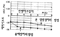
도 10은 도 9에 도시한 본 발명의 도입효과를 설명하는 도면이다. 그래프는 광자기기록매체에 마크에지기록을 실행한 경우의 재생신호에 있어서의 마크에지위치의 측정결과의 1예이다. 검은점(■)으로 나타낸 곡선은 종래장치, 흰점(□)으로 나타낸 곡선은 본 발명에 의한 장치의 결과를 나타낸다. 본 측정에서는 2개의 마크간격을 고정시켜 선행마크길이에 대한 후속마크형상의 변화를 측정하였다. 여기서,마크간격 및 후속마크길이는 부호기(113)의 부호화규칙에 있어서의 최단인 2L로 하고, 선행마크길이는 2L∼8L의 범위에서 변화시켰다. 광스폿직경은 약 1.2㎛, 검출창폭L은 0.27㎛이다. △E는 후속마크앞쪽에지의 이상(理想) 위치로부터의 시프트를 의미하고, 시프트량의 부호는 늦어지는 방향이 정이다. 점(□,■)은 △E가 검출창폭L에 차지하는 비율을 퍼센트(%)로 해서 나타내었다. 종래장치에서는 선행마크가 길어질수록 앞쪽에지는 앞으로 서서히 시프트된다. 또, 특히 선행 마크가 3L이상인 경우에는 선행마크가 2L인 경우보다 크게 시프트하고 있다. 즉, 바꿔말하면, 선행마크가 3L이상인 경우, 후속마크는 선행마크가 2L인 경우에 비해 상당히 크게 형성되어 있다는 것이다. 이들 에지시프트는 이상마크를 형성할 수 있으면, 선행마크길이에 관계없이 일정하다. 또, 일정하면 신호처리에 의해서 제거할 수 있지만, 선행마크길이에 의존해서 변화한 경우에는 제거가 곤란하게 된다. 따라서, 데이타의 안정된 기록재생을 위해서는 이들 에지시프트가 선행마크 길이에 관계없이 거의 일정한 것이 바람직하다. 종래장치에서는 마크형성기간 직후에 가열을 휴지하는 열차단기간(도 2의 (d)의 Pb레벨의 기간)을 항상 일정길이만큼 마련하고, 선행스페이스길이에 따른 열간섭의 보상 즉 거리에 관한 열간접의 보상을 실행하고 있었다. 즉, 일정길이의 가열휴지기간에 의해서 선행마크길이, 선행스페이스길이에 관계없이 에지시프트는 거의 일정하게 되도록 하고 있었다. 이것은 선행마크로부터의 열전도효과와 마크비형성기간에 있어서의 예열기간(도 2의 (d)의 Pa레벨의 기간)의 효과가 균형을 이루고, 그의 합이 항상 대략 일정하게 되는 것에 의해서 그 직후의 마크를 안정하게 형성할 수 있도록 한 것이다. 그러나, 종래장치에서는 선행마크형성시에 투입된 열량에 관한 보상, 즉 열원의 크기에 관한 보상은 실행하고 있지 않았다. 이 때문에 기록선밀도가 상승하고, 선행마크에서 후속마크위치로의 열전도의 변화를 무시할 수 없는 경우에는 상기와 같은 문제가 발생하는 것이다.FIG. 10 is a view for explaining the introduction effect of the present invention shown in FIG. The graph is an example of the measurement result of the mark edge position in the reproduction signal when the mark edge recording is performed on the magneto-optical recording medium. The curve represented by the black point (■) is the conventional device, and the curve represented by the white point (□) represents the result of the device according to the present invention. In this measurement, two mark intervals were fixed to measure the change of the subsequent mark shape with respect to the preceding mark length. Here, the mark interval and subsequent mark length were 2L, which is the shortest in the coding rule of the
이와 같이 종래장치에서는 고선밀도기록에 한계가 존재한다. 도 10의 검은점(■)을 상세하게 검토하면, 선행마크길이가 최단인 2L인 경우와 3L이상인 경우에서 후속마크의 에지시프트에는 큰 차가 생긴다. 이것은 선행마크형성시에 선행마크후단에서 앞쪽(광스폿의 주사방향과 역방향) 2L이상인 부분에 마크를 형성했는지의 여부 즉 선행마크길이가 최단인 2L인지 아닌지에 따라서 후속마크에 대한 열전도가 다른 것을 나타내고 있다. 즉, 선행마크후단에서 앞쪽2L이상의 부분에 마크를 형성한 열이 후속마크위치에 열전도할지의 여부에 따라서 후속마크형상이 다른 것이다. 따라서, 후속마크를 안정하게 형성하기 위해서는 후속마크의 형성조건을 선행마크가 최단마크길이인지 아닌지에 따라서 적응적으로 보상하지 않으면 안된다. 그래서, 선행마크길이에 따라서 경우를 나누고, 후속마크의 형성조건을 적응적으로 변화시키도록 한 것이 도 9의 구성에 의한 도 2의 (d)의 기록파형이다. 후속마크의 형성조건을 조정하는 방법으로서 몇가지의 방법이 고려되지만, 도 9의 경우 즉 도 2의 (d)의 기록파형에서는 열차단기간의 길이를 변화시키는 방법을 선택하고 있다. 즉, 선행마크길이가 3L이상으로서 후속마크형성위치에 과잉의 열전도가 예상되는 경우에는 열차단기간을 연장하는 것에 의해서 예열량을 감소시켜 보상을 실행한다. 그 결과, 도 10의 흰점(□)에서는 선행마크길이에 관계없이 후속마크의 에지위치가 안정되어 있고, 이상에 가까운 마크형성이 실행되고 있는 것을 확인할 수 있었다. 본예에서는 후속마크의 형성조건을 조정하는 방법으로서 열차단기간의 길이를 변화시키는 예를 설명했지만, 이것은 상술한 바와 같이 도 2의 (c)에 도시한 바와 같이 후속마크 자체에 대응하는 기록파형을 변화시키는 등의 다른 방법을 사용해도 좋다.As described above, there is a limit to the high linear density recording in the conventional apparatus. Examining the black point (■) in Fig. 10 in detail, a large difference occurs in the edge shift of the subsequent mark in the case where the preceding mark length is 2L, which is the shortest, and when it is 3L or more. This means that the thermal conductivity of the subsequent mark is different depending on whether or not the mark is formed in the part of 2L or more in front (reverse to the scanning direction of the optical spot) at the end of the preceding mark when forming the preceding mark, that is, whether or not the leading mark is the shortest 2L. It is shown. In other words, the shape of the subsequent mark is different depending on whether or not the heat formed by the mark at the portion of the front 2L or more in front of the preceding mark is thermally conducted at the subsequent mark position. Therefore, in order to form a subsequent mark stably, the formation conditions of the subsequent mark must be adaptively compensated according to whether or not the preceding mark is the shortest mark length. Thus, it is the recording waveform of FIG. 2 (d) by the configuration of FIG. 9 that divides the case according to the preceding mark length and adaptively changes the formation conditions of the subsequent marks. Several methods are considered as a method of adjusting the formation conditions of the subsequent marks, but in the case of FIG. 9, that is, the recording waveform of FIG. In other words, when excessive heat conduction is expected at a subsequent mark formation position with a preceding mark length of 3L or more, compensation is performed by reducing the amount of preheating by extending the thermal cutoff period. As a result, it was confirmed that the edge position of the subsequent mark was stable at the white point (□) in Fig. 10, and the mark formation near the above was performed. In this example, the example of changing the length of the thermal cut-off period as a method of adjusting the formation conditions of the subsequent marks has been described. However, as described above, this changes the recording waveform corresponding to the subsequent marks itself as shown in Fig. 2C. You may use another method, such as making it let.
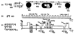
도 4의 (a)∼(j) 및 도 5, 도 6은 도 2의 기록패턴인식기(302)의 동작을 설명하기 위해 마크배열과 그것을 기록하는 기록파형을 도시한 도면이다. 도 4의 (a), 도 5의 (a), 도 6의 (a)는 기록부호열에 대응해서 기록매체상에 형성할 마크배열의 이미지를 도시하고 있고. L은 마크(400), (500), (600), 스페이스(402), (502), (602)의 길이의 변화량의 최소단위(채널비트길이)이다. 기록 재생용의 레이저광스폿은 도 4의 (a), 도 5의 (a), 도 6의 (a)중 좌측에서 우측으로 주사한다. 여기서, 마크(401), (501), (601) 및 스페이스(402), (502), (602)의 목표에지간격은 반드시 L의 정수배이다.4 (a) to (j), and FIGS. 5 and 6 are diagrams showing mark arrays and recording waveforms for recording them in order to explain the operation of the
도 4의 (b)는 기준시간신호로서 기록처리계를 제어하는 주기T의 클럭신호이면, 기록파형을 포함한 기록처리계의 신호는 이 클럭신호와 동기해서 생성, 전달된다. T는 채널비트길이L에 상당하는 검출창의 기간의 길이로서, 레이저광스폿의 이동속도를 v로 하면 L=vT의 관계에 있다. 클럭(403)은 듀티50%의 직사각형파(矩形波)이고, 하이레벨, 로우레벨의 기간은 모두 Tw와 동일하다. 본 실시예에 있어서는 T=2Tw의 관계가 있고, 이하에 설명하는 각 에너지레벨의 유지시간은 Tw의 정수배 즉 기준시간신호의 주기T의 정수배 또는 반기수배로 되어 있다.4B is a clock signal of a period T that controls the recording processing system as the reference time signal, the signal of the recording processing system including the recording waveform is generated and transmitted in synchronization with this clock signal. T is the length of the period of the detection window corresponding to the channel bit length L. When the moving speed of the laser light spot is v, L = vT. The clock 403 is a rectangular wave having a duty of 50%, and the periods of the high level and the low level are equal to Tw. In this embodiment, there is a relationship of T = 2Tw, and the holding time of each energy level described below is an integer multiple of Tw, that is, an integer multiple or a half cycle multiple of the period T of the reference time signal.
도 4의 (c)는 종래기술에 의한 정보기록장치의 기록파형의 예를 설명하는 도면이다. 기록파형은 마크형성에 필요한 고레벨의 에너지를 간헐적으로 조사하는 마크형성기간과 스페이스에 대응하는 마크형성기간 이외의 마크비형성기간으로 크게 구별된다. 마크형성기간에서는 에너지레벨Pa, Pb, Pw1, Pw2중의 어느 하나의 레벨이 발생되고 있고, 마크비형성기간에서는 Pb, Pa의 에너지레벨이 순차 발생된다. 본 기록파형에서는 직전의 마크길이, 스페이스길이 즉 선행하는 기록패턴과 관계없이 고정된 에너지레벨이 고정된 순서에 따라 대응하는 마크길이 및 스페이스 길이만을 반영해서 순차 출력될 뿐이다. 즉, 2T길이의 마크에 대응하는 마크형성기간은 폭Tw, 레벨Pw1의 펄스1발로 구성되어 있고,이후 마크길이가 T연장될 때마다 폭Tw, 레벨Pw2의 펄스가 반복 주기T로 1발씩 부가된다. 또, 레벨Pw1, Pw2의 펄스간의 레벨은 항상 Pb이고, 마크비형성기간에는 선두에 폭Tb=3Tw, 레벨 Pb의 저레벨기간이 마련되고, 그 후 마크형성기간까지 Pa의 레벨이 유지된다.4C is a diagram for explaining an example of a recording waveform of the information recording apparatus according to the prior art. The recording waveform is largely divided into a mark forming period for intermittently irradiating high levels of energy required for mark formation and a mark non-forming period other than the mark forming period corresponding to the space. In the mark formation period, one of the energy levels Pa, Pb, Pw1, and Pw2 is generated. In the mark ratio formation period, the energy levels of Pb and Pa are sequentially generated. In this recording waveform, irrespective of the immediately preceding mark length, space length, i.e., the preceding recording pattern, the fixed energy level is only output in order reflecting only the corresponding mark length and space length in a fixed order. That is, the mark formation period corresponding to the mark of 2T length is composed of one pulse of width Tw and level Pw1, and thereafter, pulses of width Tw and level Pw2 are added one by one in the repetition period T each time the mark length is extended. do. In addition, the level between the pulses of the levels Pw1 and Pw2 is always Pb. In the mark ratio forming period, the width Tb = 3Tw and the low level period of the level Pb are provided at the beginning, and then the level of Pa is maintained until the mark forming period.
도 4의 (d)는 본 발명에 의한 정보기록장치의 기록파형의 1에를 설명하는 도면이다. 마크형성기간에는 처음에 Pw1, Pa1, Pw3, Pa2, Pw2, Pb, 이후 Pw2, Pb1의 반복으로 이루어지는 패턴에 따라서 에너지레벨을 순차 출력하고 있고. 기록파형의 상엔벌로프 및 하엔벌로프가 이 마크형성기간 개시로부터의 시간경과에 따라서 저하하고 있다. 또, 각 레벨은 유지시간은 Tw와 동일하다. 또, 마크비형성기간에는 선두에 레벨Pb의 기간 Tb(=3Tw)가 마련되고, 그 후 마크형성기간까지 Pa의 레벨이 유지된다.4D is a diagram for explaining one of recording waveforms of the information recording apparatus according to the present invention. In the mark formation period, energy levels are sequentially output in accordance with a pattern consisting of repetition of Pw1, Pa1, Pw3, Pa2, Pw2, Pb, and then Pw2, Pb1. The upper envelope and lower envelope of the recording waveform are decreasing with the passage of time from the start of this mark formation period. In addition, the maintenance time of each level is equal to Tw. In the mark ratio formation period, a period Tb (= 3Tw) of level Pb is provided at the beginning, and then the level of Pa is maintained until the mark formation period.
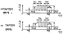
도 4의 (e)는 본 발명에 의한 정보기록장치의 기록파형의 다른 1예를 설명하는 도면이다. 마크형성기간에 있어서는 기록파형의 상엔벌로프 및 하엔벌로프가 이 마크형성기간 개시로부터의 시간경과에 따라서 저하하고 있고, 각 레벨의 유지시간은 Tw와 동일하다. 본 기록파형은 선행하는 기록패턴 즉 직전의 마크길이를 참조해서 마크비형성기간의 기록파형이 적응적으로 변화하는 예이다. 즉, 2T길이의 마크를 형성하는 경우의 마크형성기간은 폭Tw, 레벨Pw1의 펄스1발로 구성되어 있고, 이후 마크길이가 T연장될 때마다 폭Tw, 레벨Pw2의 펄스가 반복 주기T로 1 발씩 부가된다. 또, 레벨Pw1의 펄스와 Pw2의 펄스간의 레벨은 Pa이고, 레벨 Pw2의 펄스끼리 사이의 레벨은 Pb이다. 또, 마크비형성기간에는 선두에 레벨Pb의 기간이 마련되고, 그 후 마크형성기간 직전까지 Pa의 레벨이 유지된다. 레벨Pb의 기간은 선행하는 마크길이가 2T인 경우 Tb1(=3Tw), 3T이상인 경우 Tb2(=4Tw)로 적응적으로 변화한다. 본예에 있어서는 간단화를 위해 마크형성기간의 상엔벌로프를 형성하는 에너지레벨을 2레벨, 하엔벌로프를 형성하는 에너지레벨을 2레벨로 해서 설명하고 있지만, 이것은 특히 에너지레벨수를 한정하는 의미의 것은 아니다. 즉, 도 4의 (d)에 도시한 바와 같이 상엔벌로프를 형성하는 에너지레벨, 하엔벌로프를 형성하는 에너지레벨로 각각 3레벨 이상을 사용해도 좋다. 이것은 이후의 도 4의 (f)∼(j)에서 설명되는 실시예에 있어서도 공통이다.4E is a diagram for explaining another example of the recording waveform of the information recording apparatus according to the present invention. In the mark forming period, the upper envelope and the lower envelope of the recording waveform decrease with the passage of time from the start of the mark forming period, and the holding time of each level is equal to Tw. This recording waveform is an example in which the recording waveform of the mark non-forming period is adaptively changed with reference to the preceding recording pattern, that is, the immediately preceding mark length. That is, in the case of forming a mark of 2T length, the mark forming period is composed of one pulse of width Tw and level Pw1, and thereafter, a pulse of width Tw and level Pw2 is repeated as a repetition period T every time the mark length is extended. Step by step is added. The level between the pulses of the level Pw1 and the pulses of the Pw2 is Pa, and the level between the pulses of the level Pw2 is Pb. In the mark ratio formation period, a period of level Pb is provided at the beginning, and then the level of Pa is maintained until immediately before the mark formation period. The period of the level Pb is adaptively changed to Tb1 (= 3Tw) when the preceding mark length is 2T, and Tb2 (= 4Tw) when 3T or more. In the present example, for the sake of simplicity, the energy level for forming the upper envelope of the mark forming period is described as two levels, and the energy level for forming the lower envelope is set to two levels, but this is particularly meant to limit the number of energy levels. It is not. That is, as shown in Fig. 4D, three or more levels may be used as the energy level for forming the upper envelope and the energy level for forming the lower envelope, respectively. This is also common in the embodiments described later in FIGS. 4 (f) to (j).
도 4의 (f)는 본 발명에 의한 정보기록장치의 기록파형의 다른 1예를 설명하는 도면이다. 마크형성기간에 있어서는 기록파형의 상엔벌로프 및 하엔벌로프가 이 마크형성기간 개시로부터의 시간경과에 따라서 저하하고 있고, 각 레벨의 유지시간은 Tw와 동일하다. 본 기록파형은 선행하는 기록패턴 즉 직전의 마크길이를 참조해서 마크비형성기간의 기록파형이 적응적으로 변화하는 예이다. 즉, 2T길이의 마크를 형성하는 경우의 마크형성기간은 폭Tw, 레벨Pw1의 펄스1발로 구성되어 있고, 이후 마크길이가 T연장될 때마다 폭Tw, 레벨Pw2의 펄스가 반복 주기T로 1발씩 부가된다. 레벨Pw1의 펄스와 Pw2의 펄스간의 레벨은 Pa이고, 레벨Pw2의 펄스끼리 사이의 레벨은 Pb이다. 또, 마크비형성기간에는 선두에 레벨Pb의 기간 Tb(=3Tw)가 마련되고, 그 후 마크형성기간 직전까지 Pa1 또는 Pa2의 레벨이 유지된다. 레벨Pa1, Pa2는 선행하는 마크길이가 2T인 경우 Pa1, 3T이상인 경우 Pa2로 적응적으로 선택된다.4F is a diagram for explaining another example of the recording waveform of the information recording apparatus according to the present invention. In the mark forming period, the upper envelope and the lower envelope of the recording waveform decrease with the passage of time from the start of the mark forming period, and the holding time of each level is equal to Tw. This recording waveform is an example in which the recording waveform of the mark non-forming period is adaptively changed with reference to the preceding recording pattern, that is, the immediately preceding mark length. That is, in the case of forming a mark of 2T length, the mark forming period is composed of one pulse of width Tw and level Pw1, and thereafter, a pulse of width Tw and level Pw2 is repeated as a repetition period T every time the mark length is extended. Step by step is added. The level between the pulses of the level Pw1 and the pulses of the Pw2 is Pa, and the level between the pulses of the level Pw2 is Pb. In the mark ratio formation period, the period Tb (= 3Tw) of the level Pb is provided at the beginning, and then the level of Pa1 or Pa2 is maintained until immediately before the mark formation period. Levels Pa1 and Pa2 are adaptively selected as Pa1 when the preceding mark length is 2T, or Pa2 when 3T or more.
도 4의 (g)는 본 발명에 의한 정보기록장치의 기록파형의 다른 1예를 설명하는 도면이다. 마크형성기간에 있어서는 기록파형의 상엔벌로프 및 하엔벌로프가 이 마크형성기간 개시로부터의 시간경과에 따라서 저하하고 있고, 각 레벨의 유지시간은 Tw와 동일하다. 본 기록파형은 선행하는 기록패턴 즉 직전의 마크길이를 참조해서 마크비형성기간의 기록파형이 적응적으로 변화하는 예이다. 즉, 2T길이의 마크를 형성하는 경우의 마크형성기간은 폭Tw, 레벨Pw1의 펄스1발로 구성되어 있고, 이후 마크길이가 T연장될 때마다 폭Tw, 레벨Pw2의 펄스가 반복 주기T로 1발씩 부가된다. 레벨Pw1의 펄스와 레벨Pw2의 펄스간의 레벨은 Pa이고, 레벨Pw2의 펄스끼리 사이의 레벨은 Pb이다. 또, 마크비형성기간에는 선두에 기간 Th1(=Tw) 또는 Th2(=2Tw), 레벨Pa의 기간이 마련되고, 그 후 레벨Pb, 기간 Tb(=3Tw)의 기간을 거쳐서 마크형성기간 직전까지 Pa의 레벨이 유지된다. 기간 Th1, Th2는 선행하는 마크길이가 2T인 경우 Th1, 3T이상인 경우 Th2로 적응적으로 선택된다.4G is a diagram for explaining another example of the recording waveform of the information recording apparatus according to the present invention. In the mark forming period, the upper envelope and the lower envelope of the recording waveform decrease with the passage of time from the start of the mark forming period, and the holding time of each level is equal to Tw. This recording waveform is an example in which the recording waveform of the mark non-forming period is adaptively changed with reference to the preceding recording pattern, that is, the immediately preceding mark length. That is, in the case of forming a mark of 2T length, the mark forming period is composed of one pulse of width Tw and level Pw1, and thereafter, a pulse of width Tw and level Pw2 is repeated as a repetition period T every time the mark length is extended. Step by step is added. The level between the pulses of the level Pw1 and the pulses of the level Pw2 is Pa, and the level between the pulses of the level Pw2 is Pb. In the mark non-forming period, a period of the period Th1 (= Tw) or Th2 (= 2 Tw) and the level Pa is provided at the beginning, and thereafter, through the periods of the level Pb and the period Tb (= 3Tw) until immediately before the mark formation period. The level of Pa is maintained. The periods Th1 and Th2 are adaptively selected as Th1 when the preceding mark length is 2T and Th2 when 3T or more.
도 4의 (h)는 본 발명에 의한 정보기록장치의 기록파형의 다른 1예를 설명하는 도면이다. 마크형성기간에 있어서는 기록파형의 상엔벌로프 및 하엔벌로프가 이 마크형성기간 개시로부터의 시간경과에 따라서 저하하고 있다. 본 기록파형은 선행하는 기록패턴 즉 직전의 마크길이를 참조해서 마크형성기간 선두의 기록파형이 적응적으로 변화하는 예이다. 즉, 2T길이의 마크를 형성하는 경우의 마크형성기간은 폭Tw1(=2Tw) 또는 Tw2(=Tw), 레벨Pw1의 펄스1발로 구성되어 있고, 이후 마크길이가 T연장될 때마다 폭Tw, 레벨Pw2의 펄스가 반복 주기T로 1발씩 부가된다. 레벨Pw1의 기간은 선행하는 마크길이가 2T인 경우 Tw1, 3T이상인 경우 Tw2로 적응적으로 변화한다. 레벨Pw1의 펄스와 레벨Pw2의 펄스간의 레벨은 Pa이고, 레벨Pw2의 펄스끼리 사이의 레벨은 Pb이다. 또, 마크비형성기간에는 선두에 레벨Pb, 기간Tb(=3Tw)의 구간이 마련되고, 그 후 마크형성기간 직선까지 Pa의 레벨이 유지된다.Fig. 4H is a view for explaining another example of the recording waveform of the information recording apparatus according to the present invention. In the mark forming period, the upper envelope and the lower envelope of the recording waveform are decreasing with the passage of time from the start of the mark forming period. This recording waveform is an example in which the recording waveform at the head of the mark forming period is adaptively changed with reference to the preceding recording pattern, that is, the immediately preceding mark length. That is, the mark formation period in the case of forming a mark having a length of 2T is composed of a width Tw1 (= 2Tw) or Tw2 (= Tw) and one pulse of the level Pw1, and thereafter the width Tw, Pulses of level Pw2 are added once per repetition period T. The period of level Pw1 is adaptively changed to Tw1 when the preceding mark length is 2T, and Tw2 when 3T or more. The level between the pulses of the level Pw1 and the pulses of the level Pw2 is Pa, and the level between the pulses of the level Pw2 is Pb. In the mark ratio forming period, a section of level Pb and period Tb (= 3Tw) is provided at the beginning, and then the level of Pa is maintained until the straight line of the mark forming period.
도 4의 (i)는 본 발명에 의한 정보기록장치의 기록파형의 다른 1예를 설명하는 도면이다. 마크형성기간에 있어서는 기록파형의 상엔벌로프 및 하엔벌로프가 이 마크형성기간 개시로부터의 시간경과에 따라서 저하하고 있고. 또 각 레벨의 유지시간은 Tw와 동일하다. 본 기록파형은 선행하는 기록패턴 즉 직전의 마크길이를 참조해서 마크형성기간 선두의 기록파형이 적응적으로 변화하는 예이다. 즉, 2T길이의 마크를 형성하는 경우의 마크형성기간은 폭Tw, 레벨Pw1 또는 Pw3의 펄스1발로 구성되어 있고, 이후 마크길이가 T연장될 때마다 폭Tw, 레벨Pw2의 펄스가 반복 주기T로 1발씩 부가된다. 레벨Pw1, Pw3의 결정은 선행하는 마크길이가 2T인 경우 Tw1, 3T이상인 경우 Tw3으로 적응적으로 선택된다. 레벨Pw1의 펄스와 레벨Pw2의 펄스간, 레벨Pw2의 펄스와 레벨Pw3의 펄스간의 레벨은 Pa이고, 레벨Pw2의 펄스끼리 사이의 레벨은 Pb이다. 또, 마크비형성기간에는 선두에 레벨Pb, 기간Tb(=3Tw)의 구간이 마련되고, 그 후 마크형성기간 직전까지 Pa의 레벨이 유지된다.4 (i) is a diagram for explaining another example of the recording waveform of the information recording apparatus according to the present invention. In the mark forming period, the upper envelope and the lower envelope of the recording waveform are decreasing with the passage of time from the start of the mark forming period. The holding time of each level is equal to Tw. This recording waveform is an example in which the recording waveform at the head of the mark forming period is adaptively changed with reference to the preceding recording pattern, that is, the immediately preceding mark length. That is, the mark formation period in the case of forming a mark having a length of 2T is composed of one pulse of width Tw, level Pw1 or Pw3, and the pulses of width Tw and level Pw2 are repeated every time the mark length is extended. It is added one by one. The determination of the levels Pw1 and Pw3 is adaptively selected as Tw1 when the preceding mark length is 2T and Tw3 when 3T or more. The level between the pulses of the level Pw1 and the pulses of the level Pw2, the pulses of the level Pw2 and the pulses of the level Pw3 is Pa, and the level between the pulses of the level Pw2 is Pb. In the mark non-forming period, a period Pb and a period Tb (= 3 Tw) are provided at the beginning, and then the level of Pa is maintained until immediately before the mark forming period.
도 4의 (j)는 본 발명에 의한 정보기록장치의 기록파형의 다른 1예를 설명하는 도면이다. 마크형성기간에 있어서는 기록파형의 상엔벌로프 및 하엔벌로프가 이 마크형성기간 개시로부터의 시간경과에 따라서 저하하고 있다. 본 기록파형은 선행하는 기록패턴 즉 직전 마크길이를 참조해서 마크형성기간 선두의 기록파형이 적응적으로 변화하는 예이다. 즉, 2T길이의 마크를 형성하는 경우의 마크형성기간은 폭Tw, 레벨Pw1 또는 Pw3의 펄스1발로 구성되어 있고, 직후에 Tm1(=2Tw) 또는 Tm2(=Tw)의 기간을 두고 이후 마크길이가 T연장될 때마다 폭Tw, 레벨Pw2의 펄스가 반복 주기T로 1발씩 부가된다. 폭Tm1, Tm2의 결정은 선행하는 마크길이가 2T인 경우 Tm1, 3T이상인 경우 Tm2로 적응적으로 선택된다. 레벨Pw1의 펄스와 레벨Pw2의 펄스간의 레벨은 Pa이고, 레벨Pw2의 펄스끼리 사이의 레벨은 Pb이다. 또, 마크비형성기간에는 선두에 레벨Pb, 기간Tb(=3Tw)의 구간이 마련되고, 그 후 마크형성기간 직전까지 Pa의 레벨이 유지된다.4 (j) is a diagram for explaining another example of the recording waveform of the information recording apparatus according to the present invention. In the mark forming period, the upper envelope and the lower envelope of the recording waveform are decreasing with the passage of time from the start of the mark forming period. This recording waveform is an example in which the recording waveform at the head of the mark formation period is adaptively changed with reference to the preceding recording pattern, that is, the immediately preceding mark length. That is, the mark formation period in the case of forming the mark of 2T length is composed of one pulse of the width Tw, the level Pw1 or the Pw3, and immediately after the period of Tm1 (= 2Tw) or Tm2 (= Tw), the mark length Each time T is extended, pulses of the width Tw and the level Pw2 are added once per repetition period T. The determination of the widths Tm1 and Tm2 is adaptively selected as Tm1 when the preceding mark length is 2T and Tm2 when 3T or more. The level between the pulses of the level Pw1 and the pulses of the level Pw2 is Pa, and the level between the pulses of the level Pw2 is Pb. In the mark non-forming period, a period Pb and a period Tb (= 3 Tw) are provided at the beginning, and then the level of Pa is maintained until immediately before the mark forming period.
도 5의 (c)는 본 발명에 의한 정보기록장치의 기록파형의 다른 1예를 설명하는 도면이다. 마크형성기간에 있어서는 기록파형의 하엔벌로프가 이 마크형성 기간 개시로부터의 시간경과에 따라서 저하하고 있다. 본 기록파형은 자기의 스페이스길이를 참조해서 마크비형성기간 자신의 기록파형이 적응적으로 변화하는 예이다. 즉, 2T길이의 스페이스를 형성하는 경우의 마크비형성기간은 전후에 폭Tw, 레벨Pb의 기간을 마련한 폭4Tw, 레벨Pa의 기간으로 구성되어 있다. 3T길이 이상의 스페이스를 형성하는 경우의 마크형성기간은 선두에 폭Tb1(=2Tw), 레벨Pb의 기간이, 최후에 폭Tb2(=Tw), 레벨Pb의 기간에 계속되는 폭Th(=Tw), 레벨Pa의 기간으로 구성되어 있고, 이후 마크길이가 T연장될 때마다 전후에 레벨Pb의 기간을 수반하는 레벨Pa의 기간이 T씩 연장된다. 한편, 마크형성기간의 기록파형은 2T길이의 마크를 형성하는 경우의 마크형성기간은 폭Tw, 레벨Pw1의 펄스1발이고, 3T길이의 마크를 형성하는 경우의 마크형성기간은 폭Tw, 레벨Pw1의 펄스에 계속해서 폭Tw, 레벨Pa의 기간을 전치(前置)한 폭Tw, 레벨Pw1의 펄스로 구성된다. 이후, 마크길이가 T연장될때마다 폭Tw, 레벨Pb의 기간을 전치해서 폭Tw, 레벨Pw2의 펄스가 1발씩 부가된다.FIG. 5C is a diagram for explaining another example of the recording waveform of the information recording apparatus according to the present invention. In the mark forming period, the lower envelope of the recording waveform decreases with the passage of time from the start of this mark forming period. This recording waveform is an example in which the recording waveform of the mark non-forming period itself is adaptively changed with reference to the space length thereof. That is, the mark ratio formation period in the case of forming a space of 2T length is composed of a width Tw and a width 4Tw and a level Pa period before and after the width Tw and the level Pb. In the case of forming a space having a length of 3T or more, the mark forming period has a width Tb1 (= 2Tw) at the beginning, a width Pb2 (= Tw) last, a width Th (= Tw) following the period Pb, It is composed of a period of the level Pa, and the period of the level Pa accompanying the period of the level Pb is extended by T before and after each time the mark length is extended. On the other hand, the recording waveform of the mark formation period is the mark formation period when the mark of 2T length is formed by one pulse of width Tw and the level Pw1, and the mark formation period when the mark of the 3T length is formed by the width Tw and level. Following the pulse of Pw1, the width Tw, the width Tw which transposed the period of the level Pa, and the pulse of the level Pw1 are comprised. Thereafter, whenever the mark length is extended, pulses of the width Tw and the level Pw2 are added one by one by transposing the periods of the width Tw and the level Pb.
도 6의 (c)는 본 발명에 의한 정보기록장치의 기록파형의 다른 1예를 설명하는 도면이다. 마크형성기간에 있어서는 기록파형의 하엔벌로프가 이 마크형성 기간 개시로부터의 시간경과에 따라서 저하하고 있다. 본 기록파형은 자기의 스페이스길이를 참조해서 마크비형성기간 자신의 기록파형이 적응적으로 변화하는 예이다. 즉, 4T길이 이하의 스페이스를 형성하는 경우의 마크비형성기간은 선두에 폭Tb1(=2Tw), 레벨Pb의 기간이, 최후에 폭Tb2(=Tw), 레벨Pb의 기간에 계속해서 폭Th(=Tw), 레벨Pa의 기간을 마련한 레벨Pa의 기간으로 구성되어 있다. 5Tw길이 이상의 스페이스를 형성하는 경우의 마크형성기간은 선두에 폭Tb2(=Tw), 레벨Pb의 기간이, 최후에 폭Tb2(=Tw), 레벨Pb의 기간에 계속해서 폭Th(=Tw), 레벨Pa의 기간으로 구성되어 있고, 이후 마크길이가 T연장될 때마다 전후에 레벨 Pb의 기간을 수반하는 레벨Pa의 기간이 T씩 연장된다. 한편, 마크형성기간의 기록파형은 2T길이의 파크를 형성하는 경우의 마크형성기간에는 폭Tw, 레벨Pw1의 펄스1발이고, 3T길이의 마크를 형성하는 경우의 마크형성기간은 폭Tw, 레벨Pw1의 펄스에 계속해서 폭Tw, 레벨Pa의 기간을 전치한 폭Tw, 레벨Pw1의 펄스로 구성된다. 이후, 마크길이가 T연장될때마다 폭Tw, 레벨Pb의 기간을 전치한 폭Tw1, 레벨Pw2의 펄스가 1발씩 부가된다.6C is a diagram for explaining another example of the recording waveform of the information recording apparatus according to the present invention. In the mark forming period, the lower envelope of the recording waveform decreases with the passage of time from the start of this mark forming period. This recording waveform is an example in which the recording waveform of the mark non-forming period itself is adaptively changed with reference to the space length thereof. That is, in the case of forming a space having a length of 4T or less, the mark ratio formation period is at the beginning of the width Tb1 (= 2Tw) and the period of the level Pb, and lastly the width Tb2 (= Tw) and the period of the level Pb. (= Tw), it consists of the period of level Pa which provided the period of level Pa. In the case of forming a space having a length of 5 Tw or more, the mark forming period has a width Tb2 (= Tw) at the beginning and a period Pb last, with a width Tb2 (= Tw) at the end and a width Th (= Tw) after the period of the level Pb. The period of the level Pa, which is composed of the period of the level Pa, and the period of the level Pa accompanied by the period of the level Pb is extended by T before and after each time the mark length is extended. On the other hand, the recording waveform of the mark formation period is one pulse of width Tw and level Pw1 in the mark formation period in the case of forming a park of 2T length, and the mark formation period in the case of forming a mark of 3T length is width Tw and level. Following the pulse of Pw1, it consists of the width Tw and the width Pw1 which transposed the period of the level Pa, and the pulse of the level Pw1. Thereafter, whenever the mark length is extended, pulses of the width Tw1 and the level Pw2 transposing the periods of the width Tw and the level Pb are added one by one.
마지막으로, 종래 기록파형 및 본 발명에 의한 기록파형에 의해서 마크에지 기록을 실행한 경우의 비례파워설정값과 지터의 관계를 도 7에 도시한다. 부호기의 변조규칙은 (1, 7)코드, 광원파장685nm, 대물렌즈개구수0. 55의 광학계를 사용하고, 기록선밀도0. 40㎛/bit로 기록을 실행한 경우의 결과이다. 점선의 흰점(…△…)은 종래 기록파형에 의한 기록으로서 앞쪽에지끼리의 간격을, 점선의 검은점(…▲…)은 종래 기록파형에 의한 기록으로서 뒤쪽에지끼리의 간격을 측정한 경우의 대검출창폭비 지터이다. 종래 기록파형에서는 선행하는 기록패턴에 의존해서 마크의 앞쪽에지의 위치가 이상위치에서 변동하므로 앞쪽에지지터가 뒤쪽에지지터에 비해 전체적으로 크게 되어 있다. 또, 앞쪽에지지터를 최적화하는 파워와 뒤쪽에 지지터를 최적화하는 파워가 다르다. 이것에 대해 실선의 흰점(-○-)은 본 발명의 기록파형에 의한 기록으로서 앞쪽에지끼리의 간격을, 실선의 검은점(-●-)은 본 발명의 기록파형에 의한 기록으로서 뒤쪽에지끼리의 간격을 측정한 경우의 대검출창폭비지터이다. 본 발명의 기록파형에 의한 기록에서는 마크의 앞쪽에지가 거의 이상위치에 형성되므로 전체적으로 지터가 개선되고 동시에 앞쪽에지지터를 최적화하는 파워와 뒤쪽에지지터를 최적화하는 파워가 일치하고 있다. 또, 앞쪽에 지지터와 뒤쪽에지지터의 크기가 거의 일치하고 있고 결과로서 기록파워마진이 대폭으로 확대되어 있다.Finally, Fig. 7 shows the relationship between the proportional power setting value and jitter in the case where mark edge recording is performed by the conventional recording waveform and the recording waveform according to the present invention. The coder's modulation rule is (1, 7) code, light source wavelength 685nm,
본 발명에 의하면, 기록매체에 에너지를 조사하는 것에 의해서 기록매체에 국소적인 물리적변화를 일으켜 정보의 기록을 실행하는 정보기록장치에 있어서 고정밀도의 마크형성이 가능하게 된다. 이것에 의해 기록방식으로서 고기록선밀도화에 유리한 마크에지기록방식을 사용하는 것이 가능하게 된다. 또, 열축적의 일정화를 실현하는 것에 의해서 재생크로스토크의 일정화가 도모되어 트랙간격을 축소할 수 있으므로 결과로서 기록면밀도를 향상시킬 수 있다. 이상에 의해 기록/재생동작의 고신뢰화가 도모되고 동시에 정보기록장치 및 기록매체의 소형화가 실현되므로 비용의 점에서 유리하게 된다.According to the present invention, by irradiating energy to the recording medium, a highly accurate mark can be formed in an information recording apparatus which causes local physical change to the recording medium to record information. This makes it possible to use a mark edge recording method which is advantageous for high recording line density. In addition, by realizing the heat accumulation, the reproduction crosstalk can be made constant, and the track interval can be reduced. As a result, the recording surface density can be improved. As a result, high reliability of the recording / reproducing operation can be achieved, and at the same time, miniaturization of the information recording apparatus and the recording medium is realized, which is advantageous in terms of cost.
도 1은 본 발명에 의한 디스크장치의 구성을 설명하는 도면,1 is a view for explaining the configuration of a disk apparatus according to the present invention;
도 2는 본 발명에 의한 기록파형을 설명하는 도면,2 is a diagram for explaining a recording waveform according to the present invention;
도 3은 본 발병에 의한 디스크장치의 기록처리계 부분의 구성을 설명하는 도면,3 is a view for explaining the configuration of a recording processing system portion of a disk apparatus according to the present invention;
도 4는 본 발명에 의한 기록패턴인식기의 동작을 설명하는 도면,4 is a view for explaining the operation of the recording pattern recognizer according to the present invention;
도 5는 본 발명에 의한 기록패턴인식기의 동작을 설명하는 도면.5 is a view for explaining the operation of the recording pattern recognizer according to the present invention.
도 6은 본 발명에 의한 기록패턴인식기의 동작을 설명하는 도면.6 is a view for explaining the operation of the recording pattern recognizer according to the present invention.
도 7은 본 발명에 의한 고정밀도 마크형성의 효과를 설명하는 도면.7 is a view for explaining the effect of high precision mark formation according to the present invention;
도 8은 다른 기록파형의 조합을 설명하는 도면,8 illustrates a combination of different recording waveforms;
도 9는 본 발명에 의한 정보기록장치의 기록패턴인식기의 구성을 설명하는 도면,9 is a view for explaining the configuration of a recording pattern recognizer of the information recording apparatus according to the present invention;
도 10은 본 발명에 의한 정보기록장치의 동작원리 및 그 효과를 설명하는 도면.10 is a view for explaining the operation principle and effect of the information recording apparatus according to the present invention.
※부호의 설명※※ Explanation of code ※
110…레이저,110... laser,
111…레이저구동회로,111... Laser drive circuit,
112…기록파형발생회로,112... Recording waveform generating circuit,
113…부호기,113... Coder,
115…사용자데이타115... User data
117…광자기기록매체,117.. Magneto-optical recording media,
120…광자기재생신호,120... Magneto-optical signal,
122…재생데이타,122... Reproduction Data,
125…레벨발생신호,125... Level signal,
126…기록부호열,126... Record Code,
127…기록데이타,127... Record Data,
128…기준시간신호,128... Time signal,
129…기록처리계,129... Record Processing System,
300…마크길이 래치,300... Mark length latch,
301…스페이스길이 래치,301... Space length latch,
302…기록패턴인식기.302... Record pattern recognizer.
Claims (6)
Priority Applications (1)
| Application Number | Priority Date | Filing Date | Title |
|---|---|---|---|
| KR1020020072646A KR100522314B1 (en) | 1996-12-26 | 2002-11-21 | Information recording apparatus |
Applications Claiming Priority (2)
| Application Number | Priority Date | Filing Date | Title |
|---|---|---|---|
| JP34714396 | 1996-12-26 | ||
| JP96-347143 | 1996-12-26 |
Related Child Applications (1)
| Application Number | Title | Priority Date | Filing Date |
|---|---|---|---|
| KR1020020072646A Division KR100522314B1 (en) | 1996-12-26 | 2002-11-21 | Information recording apparatus |
Publications (2)
| Publication Number | Publication Date |
|---|---|
| KR19980064227A KR19980064227A (en) | 1998-10-07 |
| KR100498623B1 true KR100498623B1 (en) | 2005-09-30 |
Family
ID=18388209
Family Applications (2)
| Application Number | Title | Priority Date | Filing Date |
|---|---|---|---|
| KR1019970069751A KR100498623B1 (en) | 1996-12-26 | 1997-12-17 | Information recording device |
| KR1020020072646A KR100522314B1 (en) | 1996-12-26 | 2002-11-21 | Information recording apparatus |
Family Applications After (1)
| Application Number | Title | Priority Date | Filing Date |
|---|---|---|---|
| KR1020020072646A KR100522314B1 (en) | 1996-12-26 | 2002-11-21 | Information recording apparatus |
Country Status (7)
| Country | Link |
|---|---|
| US (6) | US6104685A (en) |
| EP (1) | EP0851413B1 (en) |
| JP (2) | JP3608926B2 (en) |
| KR (2) | KR100498623B1 (en) |
| CN (4) | CN100535997C (en) |
| DE (1) | DE69731364T2 (en) |
| TW (1) | TW379323B (en) |
Families Citing this family (49)
| Publication number | Priority date | Publication date | Assignee | Title |
|---|---|---|---|---|
| US6243339B1 (en) * | 1997-08-12 | 2001-06-05 | U.S. Philips Corporation | Method and device for writing optical record carriers |
| JP3323782B2 (en) | 1997-09-09 | 2002-09-09 | 株式会社日立製作所 | How information is recorded |
| US7391698B2 (en) | 1998-07-23 | 2008-06-24 | Samsung Electronics Co., Ltd. | Adaptive writing method for high-density optical recording apparatus and circuit thereof |
| US7158461B1 (en) | 1997-12-30 | 2007-01-02 | Samsung Electronics Co., Ltd. | Adaptive writing method for high-density optical recording apparatus and circuit thereof |
| JPH11213429A (en) * | 1998-01-30 | 1999-08-06 | Sony Corp | Phase change type optical disk recording device and method therefor |
| JPH11273076A (en) * | 1998-03-23 | 1999-10-08 | Toshiba Corp | Optical information recording method and device therefor |
| MY125795A (en) * | 1998-07-23 | 2006-08-30 | Samsung Electronics Co Ltd | Adaptive writing method for high-density optical recording apparatus and circuit thereof |
| TW457476B (en) | 1998-11-06 | 2001-10-01 | Matsushita Electric Ind Co Ltd | Method and apparatus for obtaining a recording pulse condition |
| WO2000057408A1 (en) | 1999-03-19 | 2000-09-28 | Matsushita Electric Industrial Co., Ltd. | Method for optically recording information and device for optically recording information by the same |
| KR100322601B1 (en) * | 1999-06-18 | 2002-03-18 | 윤종용 | Recording method for optical disk recording, control method for optical disk recording apparatus, and recording apparatus of optical disk |
| US7272094B2 (en) * | 1999-07-15 | 2007-09-18 | Koninklike Philips Electronics N.V. | Methods and devices for recording marks in an information layer of an optical record carrier, and record carriers for use therein |
| KR100809492B1 (en) * | 1999-07-15 | 2008-03-03 | 코닌클리케 필립스 일렉트로닉스 엔.브이. | Methods and devices for recording marks in an information layer of an optical record carrier, and record carriers for use therein |
| JP2001067669A (en) * | 1999-08-31 | 2001-03-16 | Sony Corp | Recorder and recording method |
| EP1117094B1 (en) * | 2000-01-17 | 2012-11-21 | Mitsubishi Kagaku Media Co., Ltd. | Recording method for phase-change recording medium |
| TW518580B (en) * | 2000-05-11 | 2003-01-21 | Koninkl Philips Electronics Nv | Methods and devices for recording marks on a recording surface of an optical record carrier |
| US20020183882A1 (en) | 2000-10-20 | 2002-12-05 | Michael Dearing | RF point of sale and delivery method and system using communication with remote computer and having features to read a large number of RF tags |
| USRE47599E1 (en) | 2000-10-20 | 2019-09-10 | Promega Corporation | RF point of sale and delivery method and system using communication with remote computer and having features to read a large number of RF tags |
| EP1328888A4 (en) * | 2000-10-20 | 2004-10-27 | Promega Corp | Radio frequency identification method and system of distributing products |
| US6388970B1 (en) * | 2000-11-30 | 2002-05-14 | Oak Technology, Inc. | Compensation for thermal effects in CD write strategy |
| US6510120B2 (en) * | 2001-01-31 | 2003-01-21 | International Business Machines Corporation | Method for writing and/or erasing high density data on a media |
| JP4351813B2 (en) * | 2001-04-20 | 2009-10-28 | 株式会社東芝 | Optical disk device |
| JP4560251B2 (en) | 2001-09-10 | 2010-10-13 | パイオニア株式会社 | Information recording apparatus and information recording method |
| TWI242194B (en) * | 2001-09-26 | 2005-10-21 | Sony Corp | Parallel/serial conversion circuit, light output control circuit, and optical recording apparatus |
| TWI261236B (en) * | 2001-09-29 | 2006-09-01 | Samsung Electronics Co Ltd | Method for forming first state and second state on optical recording medium |
| US7525890B2 (en) * | 2001-09-29 | 2009-04-28 | Samsung Electronics Co., Ltd. | Method of and apparatus for recording data on optical recording medium |
| JP2003123252A (en) | 2001-10-09 | 2003-04-25 | Hitachi Ltd | Method and device for recording information |
| JP3740413B2 (en) * | 2001-12-20 | 2006-02-01 | 株式会社日立製作所 | High frequency superimposing method and optical disk apparatus using the same |
| US7376064B2 (en) | 2002-02-25 | 2008-05-20 | Samsung Electronics Co., Ltd. | Method and apparatus for recording data on optical recording medium |
| JP4142338B2 (en) | 2002-05-09 | 2008-09-03 | 富士フイルム株式会社 | Optical information recording method |
| KR100911140B1 (en) | 2002-06-03 | 2009-08-06 | 삼성전자주식회사 | Method and apparatus for recording data on an optical recording medium |
| JP2005530284A (en) | 2002-06-18 | 2005-10-06 | コーニンクレッカ フィリップス エレクトロニクス エヌ ヴィ | Method and apparatus for recording marks on the information layer of a record carrier |
| JP2004079078A (en) * | 2002-08-19 | 2004-03-11 | Nec Corp | Optical recording medium and its information recording method, recorder |
| CN101339777B (en) | 2003-02-19 | 2013-03-20 | 日本胜利株式会社 | Optical recording /reproducing device |
| WO2004077419A1 (en) * | 2003-02-28 | 2004-09-10 | Pioneer Corporation | Information recording device and information recording method |
| CA2467888A1 (en) | 2003-05-23 | 2004-11-23 | Matsushita Electric Industrial Co., Ltd. | Apparatus for recording information in information recording medium, information recording medium, method for recording information in information recording medium, program for recording information in information recording medium, and program product |
| EP1482486A3 (en) | 2003-05-27 | 2007-06-27 | Matsushita Electric Industrial Co., Ltd. | Optical information recording method, optical information recording device and optical information recording medium |
| JP3732499B2 (en) * | 2003-08-26 | 2006-01-05 | 株式会社リコー | Dye-type recordable DVD medium recording / reproducing method and apparatus |
| JP4179994B2 (en) | 2004-02-05 | 2008-11-12 | Tdk株式会社 | Information recording method and information recording apparatus for optical recording medium |
| JP4353023B2 (en) * | 2004-07-30 | 2009-10-28 | 株式会社日立製作所 | Test writing method, information recording method |
| US7006420B1 (en) * | 2005-02-17 | 2006-02-28 | Mediatek Incorporation | Method for tuning write strategy parameters of an optical storage device, and system thereof |
| US8369199B2 (en) * | 2005-02-17 | 2013-02-05 | Mediatek Inc. | Methods and systems for tuning at least one write strategy parameter of an optical storage device |
| JP4796796B2 (en) * | 2005-08-01 | 2011-10-19 | 株式会社日立製作所 | Information recording method and information recording apparatus |
| KR20080066855A (en) * | 2005-11-04 | 2008-07-16 | 코닌클리케 필립스 일렉트로닉스 엔.브이. | A method and device for controlling write power in a recordable optical storage system |
| JP2007335044A (en) * | 2006-06-19 | 2007-12-27 | Hitachi Ltd | Information recording device |
| US7710275B2 (en) * | 2007-03-16 | 2010-05-04 | Promega Corporation | RFID reader enclosure and man-o-war RFID reader system |
| JP2010033679A (en) * | 2008-07-30 | 2010-02-12 | Sony Corp | Optical information recording device, optical pickup, and laser beam emission method |
| JP5189064B2 (en) * | 2009-11-26 | 2013-04-24 | 日立コンシューマエレクトロニクス株式会社 | Optical disc recording method and optical disc recording apparatus |
| US20110160645A1 (en) * | 2009-12-31 | 2011-06-30 | Boston Scientific Scimed, Inc. | Cryo Activated Drug Delivery and Cutting Balloons |
| US9558607B2 (en) * | 2012-11-14 | 2017-01-31 | Infineon Technologies Ag | Relay attack prevention using RSSIPPLX |
Citations (2)
| Publication number | Priority date | Publication date | Assignee | Title |
|---|---|---|---|---|
| JPH01150230A (en) * | 1987-12-07 | 1989-06-13 | Hitachi Ltd | Information recording method |
| JPH08287465A (en) * | 1995-04-13 | 1996-11-01 | Ricoh Co Ltd | Recording method for phase change type optical disk |
Family Cites Families (21)
| Publication number | Priority date | Publication date | Assignee | Title |
|---|---|---|---|---|
| US5577015A (en) * | 1980-07-16 | 1996-11-19 | Discovision Associates | System for recording digital information in a pulse-length modulation |
| KR910003460B1 (en) | 1987-02-12 | 1991-05-31 | 가부시기가이샤 히다찌세이사꾸쇼 | Optical information-recording apparatus |
| JP2644501B2 (en) * | 1987-09-19 | 1997-08-25 | キヤノン株式会社 | Data recording / reproducing device |
| JPH05298737A (en) * | 1992-04-21 | 1993-11-12 | Hitachi Ltd | Recording and reproducing control method of information |
| US5642343A (en) | 1990-06-29 | 1997-06-24 | Hitachi, Ltd. | Magnetooptic disc apparatus and recording medium |
| JPH04265522A (en) * | 1991-02-21 | 1992-09-21 | Hitachi Ltd | Optical information recording and reproducing device |
| JPH05143993A (en) * | 1991-11-18 | 1993-06-11 | Olympus Optical Co Ltd | Optical information recording method |
| US5412626A (en) * | 1992-03-23 | 1995-05-02 | Matsushita Electric Industrial Co., Ltd. | Method of recording optical information with selective correction in pulse waveform and a recording system therefor |
| US5396490A (en) * | 1992-03-23 | 1995-03-07 | Motorola, Inc. | Packet reassembly method and apparatus |
| JP3135389B2 (en) * | 1992-10-23 | 2001-02-13 | 松下電器産業株式会社 | Information reproducing method, information recording / reproducing method, information reproducing apparatus, recording medium, and optical head |
| US5432762A (en) * | 1992-11-12 | 1995-07-11 | Teac Corporation | Detection apparatus for detecting sector marks of optical disk and optical disk access apparatus |
| US5490126A (en) * | 1993-04-07 | 1996-02-06 | Matsushita Electric Industrial Co., Ltd. | Apparatus for recording and reproducing data on a disk |
| JP2679596B2 (en) * | 1993-11-09 | 1997-11-19 | 松下電器産業株式会社 | Disc recording method and disc recording apparatus |
| JP2883538B2 (en) * | 1994-07-20 | 1999-04-19 | 株式会社東芝 | Optical information reproducing device |
| JPH08124160A (en) * | 1994-10-21 | 1996-05-17 | Sony Corp | Optical disk recording device |
| US5530688A (en) * | 1994-10-31 | 1996-06-25 | International Business Machines Corporation | Optical disk recording device using two modulated laser beams for recording information data |
| US5561656A (en) * | 1994-11-18 | 1996-10-01 | International Business Machines Corporation | Pulse width modulation optical disk drive with pulsed laser preheating between marks |
| EP0725397B1 (en) * | 1995-01-31 | 1999-09-15 | Canon Kabushiki Kaisha | Write test method for pit edge recording method and optical information recording/reproducing apparatus utilizing the same test method |
| US5732062A (en) * | 1995-10-16 | 1998-03-24 | Ricoh Company, Ltd. | Information recording apparatus, method and computer program product |
| JPH10105970A (en) * | 1996-09-27 | 1998-04-24 | Toshiba Corp | Method and device for optical information recording |
| KR100388003B1 (en) * | 1999-03-19 | 2003-06-18 | 가부시키가이샤 히타치세이사쿠쇼 | Optical information reproducing device |
-
1997
- 1997-11-25 JP JP32265497A patent/JP3608926B2/en not_active Expired - Lifetime
- 1997-12-17 DE DE69731364T patent/DE69731364T2/en not_active Expired - Lifetime
- 1997-12-17 KR KR1019970069751A patent/KR100498623B1/en not_active IP Right Cessation
- 1997-12-17 EP EP97122320A patent/EP0851413B1/en not_active Expired - Lifetime
- 1997-12-18 TW TW086119190A patent/TW379323B/en not_active IP Right Cessation
- 1997-12-22 US US08/996,096 patent/US6104685A/en not_active Expired - Lifetime
- 1997-12-26 CN CNB2005100599837A patent/CN100535997C/en not_active Expired - Lifetime
- 1997-12-26 CN CN97123458A patent/CN1111846C/en not_active Expired - Lifetime
- 1997-12-26 CN CNB031236987A patent/CN1320528C/en not_active Expired - Fee Related
-
2000
- 2000-05-18 US US09/572,379 patent/US6188658B1/en not_active Expired - Lifetime
- 2000-11-16 US US09/712,976 patent/US6430132B1/en not_active Expired - Lifetime
- 2000-11-16 US US09/712,985 patent/US6404716B1/en not_active Expired - Lifetime
-
2001
- 2001-12-18 US US10/020,211 patent/US6529466B2/en not_active Expired - Lifetime
- 2001-12-18 US US10/020,210 patent/US6512726B2/en not_active Expired - Lifetime
-
2002
- 2002-11-21 KR KR1020020072646A patent/KR100522314B1/en not_active IP Right Cessation
-
2003
- 2003-05-14 CN CN03123699A patent/CN1450534A/en active Pending
- 2003-10-29 JP JP2003368306A patent/JP3806714B2/en not_active Expired - Lifetime
Patent Citations (2)
| Publication number | Priority date | Publication date | Assignee | Title |
|---|---|---|---|---|
| JPH01150230A (en) * | 1987-12-07 | 1989-06-13 | Hitachi Ltd | Information recording method |
| JPH08287465A (en) * | 1995-04-13 | 1996-11-01 | Ricoh Co Ltd | Recording method for phase change type optical disk |
Also Published As
| Publication number | Publication date |
|---|---|
| DE69731364D1 (en) | 2004-12-02 |
| CN1111846C (en) | 2003-06-18 |
| US6512726B2 (en) | 2003-01-28 |
| JP3806714B2 (en) | 2006-08-09 |
| US6430132B1 (en) | 2002-08-06 |
| US6188658B1 (en) | 2001-02-13 |
| CN1320528C (en) | 2007-06-06 |
| EP0851413B1 (en) | 2004-10-27 |
| JP2004087125A (en) | 2004-03-18 |
| CN100535997C (en) | 2009-09-02 |
| CN1450534A (en) | 2003-10-22 |
| JPH10241164A (en) | 1998-09-11 |
| CN1681010A (en) | 2005-10-12 |
| KR100522314B1 (en) | 2005-10-18 |
| CN1186297A (en) | 1998-07-01 |
| DE69731364T2 (en) | 2006-02-02 |
| CN1516120A (en) | 2004-07-28 |
| KR19980064227A (en) | 1998-10-07 |
| US6529466B2 (en) | 2003-03-04 |
| TW379323B (en) | 2000-01-11 |
| US6104685A (en) | 2000-08-15 |
| US20020041553A1 (en) | 2002-04-11 |
| EP0851413A3 (en) | 1999-08-18 |
| US20020041558A1 (en) | 2002-04-11 |
| EP0851413A2 (en) | 1998-07-01 |
| US6404716B1 (en) | 2002-06-11 |
| JP3608926B2 (en) | 2005-01-12 |
Similar Documents
| Publication | Publication Date | Title |
|---|---|---|
| KR100498623B1 (en) | Information recording device | |
| KR100606255B1 (en) | Information recording apparatus | |
| US7961581B2 (en) | Method and apparatus for writing data on storage medium | |
| US7773483B2 (en) | Information recording apparatus | |
| JP4538362B2 (en) | Information recording device | |
| JP2000163748A (en) | Information recording system and information recording and reproducing device | |
| JPH0991788A (en) | Magneto-optical recording method and device therefor | |
| JPH0660380A (en) | Optical disk device | |
| JPH08221786A (en) | Recording waveform control method |
Legal Events
| Date | Code | Title | Description |
|---|---|---|---|
| A107 | Divisional application of patent | ||
| A201 | Request for examination | ||
| E902 | Notification of reason for refusal | ||
| E701 | Decision to grant or registration of patent right | ||
| GRNT | Written decision to grant | ||
| FPAY | Annual fee payment |
Payment date: 20130531 Year of fee payment: 9 |
|
| FPAY | Annual fee payment |
Payment date: 20140603 Year of fee payment: 10 |
|
| FPAY | Annual fee payment |
Payment date: 20150518 Year of fee payment: 11 |
|
| FPAY | Annual fee payment |
Payment date: 20160517 Year of fee payment: 12 |
|
| FPAY | Annual fee payment |
Payment date: 20170522 Year of fee payment: 13 |
|
| EXPY | Expiration of term |