KR100465099B1 - Projection lens with large reverse focal length to focal length ratio - Google Patents
Projection lens with large reverse focal length to focal length ratio Download PDFInfo
- Publication number
- KR100465099B1 KR100465099B1 KR1019970021458A KR19970021458A KR100465099B1 KR 100465099 B1 KR100465099 B1 KR 100465099B1 KR 1019970021458 A KR1019970021458 A KR 1019970021458A KR 19970021458 A KR19970021458 A KR 19970021458A KR 100465099 B1 KR100465099 B1 KR 100465099B1
- Authority
- KR
- South Korea
- Prior art keywords
- lens
- projection lens
- lens unit
- projection
- image
- Prior art date
Links
- 239000011521 glass Substances 0.000 claims abstract description 15
- 230000008859 change Effects 0.000 claims description 16
- 210000001747 pupil Anatomy 0.000 claims description 10
- 230000004075 alteration Effects 0.000 claims description 7
- 238000000034 method Methods 0.000 claims description 5
- 230000009977 dual effect Effects 0.000 claims description 2
- 230000003287 optical effect Effects 0.000 description 13
- 238000012937 correction Methods 0.000 description 12
- 230000000694 effects Effects 0.000 description 7
- 238000013461 design Methods 0.000 description 4
- 238000009826 distribution Methods 0.000 description 4
- 239000003086 colorant Substances 0.000 description 3
- 239000000463 material Substances 0.000 description 3
- 230000035945 sensitivity Effects 0.000 description 3
- 230000006866 deterioration Effects 0.000 description 2
- 238000005286 illumination Methods 0.000 description 2
- 239000004973 liquid crystal related substance Substances 0.000 description 2
- 206010010071 Coma Diseases 0.000 description 1
- 241000511976 Hoya Species 0.000 description 1
- XAGFODPZIPBFFR-UHFFFAOYSA-N aluminium Chemical compound [Al] XAGFODPZIPBFFR-UHFFFAOYSA-N 0.000 description 1
- 229910052782 aluminium Inorganic materials 0.000 description 1
- 201000009310 astigmatism Diseases 0.000 description 1
- 230000008901 benefit Effects 0.000 description 1
- 230000008878 coupling Effects 0.000 description 1
- 238000010168 coupling process Methods 0.000 description 1
- 238000005859 coupling reaction Methods 0.000 description 1
- 230000006735 deficit Effects 0.000 description 1
- 238000010586 diagram Methods 0.000 description 1
- 238000006073 displacement reaction Methods 0.000 description 1
- 230000007613 environmental effect Effects 0.000 description 1
- 229910052736 halogen Inorganic materials 0.000 description 1
- 238000004519 manufacturing process Methods 0.000 description 1
- 239000011159 matrix material Substances 0.000 description 1
- 238000005259 measurement Methods 0.000 description 1
- 238000012986 modification Methods 0.000 description 1
- 230000004048 modification Effects 0.000 description 1
- 230000008569 process Effects 0.000 description 1
- 230000001681 protective effect Effects 0.000 description 1
- 230000009467 reduction Effects 0.000 description 1
- 238000009987 spinning Methods 0.000 description 1
- 230000006641 stabilisation Effects 0.000 description 1
- 238000011105 stabilization Methods 0.000 description 1
- 230000000153 supplemental effect Effects 0.000 description 1
- 238000012546 transfer Methods 0.000 description 1
Images


Classifications
-
- G—PHYSICS
- G02—OPTICS
- G02B—OPTICAL ELEMENTS, SYSTEMS OR APPARATUS
- G02B13/00—Optical objectives specially designed for the purposes specified below
- G02B13/04—Reversed telephoto objectives
-
- G—PHYSICS
- G02—OPTICS
- G02B—OPTICAL ELEMENTS, SYSTEMS OR APPARATUS
- G02B13/00—Optical objectives specially designed for the purposes specified below
- G02B13/18—Optical objectives specially designed for the purposes specified below with lenses having one or more non-spherical faces, e.g. for reducing geometrical aberration
-
- G—PHYSICS
- G02—OPTICS
- G02B—OPTICAL ELEMENTS, SYSTEMS OR APPARATUS
- G02B9/00—Optical objectives characterised both by the number of the components and their arrangements according to their sign, i.e. + or -
- G02B9/12—Optical objectives characterised both by the number of the components and their arrangements according to their sign, i.e. + or - having three components only
Landscapes
- Physics & Mathematics (AREA)
- General Physics & Mathematics (AREA)
- Optics & Photonics (AREA)
- Lenses (AREA)
- Transforming Electric Information Into Light Information (AREA)
- Video Image Reproduction Devices For Color Tv Systems (AREA)
Abstract
본 발명에는 LCD 또는 DMD에 사용하는 투사렌즈가 제공되었다. 상기 렌즈는 세개의 렌즈로 구성된다. 즉, 음의 배율 및 두개의 비구상 표면을 가지는 최소한 하나의 플라스틱 부품을 가지는 첫번째 렌즈 유니트, 음의 배율 또는 약한 양의 배율 및 최소한 하나의 컬러 보정 이중렌즈를 가지는 두번째 렌즈 유니트 및 양의 배율 및 유리 부품상 또는 약한 플라스틱 부품상에 하나의 비구상 표면을 가지는 세 번째 렌즈 유니트로 구성된다.The present invention provides a projection lens for use in LCD or DMD. The lens consists of three lenses. That is, the first lens unit having at least one plastic part having a negative magnification and two non-spherical surfaces, the second lens unit having a negative magnification or a weak positive magnification and at least one color corrected bilens and the positive magnification and glass It consists of a third lens unit with one non-spherical surface on the part or on a weak plastic part.
상기 투사렌즈는 최소한 3.0의 역초점길이 대 초점길이비를 가지며, 상기 비는 첫번째, 두번째 및 세번째 렌즈 유니트의 배열에 의해 달성된다. 즉:The projection lens has a reverse focal length to focal length ratio of at least 3.0, which ratio is achieved by the arrangement of the first, second and third lens units. In other words:
D12/f0 > 1.0D 12 / f 0 > 1.0
D23/f0 > 0.7 , 및D 23 / f 0 > 0.7, and
1.5 < (D12 + D23 + BFL)/BFL < 4.01.5 <(D 12 + D 23 + BFL) / BFL <4.0
상기에서, f0는 첫번째, 두번째 및 세번째 렌즈 유니트 조합의 유효 초점길이이고; BFL는 투사렌즈의 긴 콘쥬게이트 측면을 따라 무한대에 위치한 대상물에 대한 첫번째, 두번째 및 세번째 렌즈 유니트 조합의 역초점길이이며; D12는 첫번째 및 두번째 렌즈 유니트 사이의 거리이고; D23은 두번째 및 세 번째 렌즈 유니트 사이의 거리이다.In the above, f 0 is the effective focal length of the first, second and third lens unit combinations; BFL is the reverse focal length of the first, second and third lens unit combinations for an object positioned at infinity along the long conjugate side of the projection lens; D 12 is the distance between the first and second lens units; D 23 is the distance between the second and third lens units.
Description
본 발명은 투사렌즈(project lens)에 관한 것으로 특히 액정 디스플레이(LCD) 또는 DMD와 같은 픽셀(pixel)로 구성된 대상물의 화상을 형성하도록 특히 사용될 수 있는 투사렌즈에 관한 것이다.FIELD OF THE INVENTION The present invention relates to a projection lens, and more particularly to a projection lens that can be used to form an image of an object composed of pixels, such as a liquid crystal display (LCD) or a DMD.
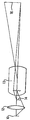
투사렌즈 시스템(project lens system, 이하 투사시스템이라 함)은 화면(viewing screen)상에 대상물의 화상을 형성하도록 하는데 사용된다. 이러한 시스템의 기본구조가 도 7에 도시되어 있으며, 여기서 10은 텅스텐-할로겐 램프와 같은 빛원이고, 12는 상기 빛원의 화상(이하 발광시스템(illumination system)의 출력(output)이라 함)을 형성하는 발광소자(illumination optics)이고, 14는 투사되는 대상물(즉, LCD패널의 온(on) 및 오프(off) 픽셀(pixel)의 매트릭스)이고, 13은 투사렌즈로서 다수의 렌즈 부품으로 구성되어 화면(16)에 대상물(14)의 확대된 화상을 형성한다. 도 7은 LCD의 경우에 대해 그린 도면이며, 발광시스템의 출력이 이 패널 후면을 친 후 투명한 픽셀을 통과한다. 이에 반하여, DMD에서는 반사후 발광시스템의 출력이 프리즘 또는 유사 장치에 의해 패널의 전면을 거치게 된다.A projection lens system (hereinafter referred to as a projection system) is used to form an image of an object on a viewing screen. The basic structure of such a system is shown in FIG. 7, wherein 10 is a light source such as a tungsten-halogen lamp, and 12 is an image of the light source (hereinafter referred to as the output of an illumination system). Are illumination optics, 14 is a projected object (i.e. matrix of on and off pixels of the LCD panel), and 13 is a projection lens composed of a plurality of lens components An enlarged image of the
대상물이 픽셀화된 패널(pixelized panel)인 투사시스템은 데이타 디스플레이(data disply) 시스템을 포함하여 다양하게 응용된다. 이러한 투사시스템은 예를들면 레드, 그린 및 블루 픽셀을 가진 하나의 싱글 패널 또는 각 색상에 대해 한 색상씩 세개의 독립된 패널들의 화상을 형성하는 하나의 투사렌즈를 양호하기로는 사용한다. 몇몇 경우에는 두개의 패널이 사용되어지는데, 두개의 색상(즉, 적색과 그린)중 하나와 한개의 색상(즉, 블루)에 대해 다른 하나로 된 패널이 사용되어진다. 스핀 필터 휠(spinning filter wheel) 또는 이와 유사한 장치가 상기 두개의 색상의 경우 상기 패널과 결합되고, 상기 패널에는 교대로 상기 필터와 동위상(synchrony)으로 두개의 색상에 대한 정보가 입력된다.Projection systems in which the object is a pixelated panel include a variety of applications, including data disply systems. Such a projection system preferably uses, for example, one single-panel with red, green and blue pixels or one projection lens which forms an image of three independent panels, one color for each color. In some cases two panels are used, one for two colors (ie red and green) and one panel for one color (ie blue). A spinning filter wheel or similar device is combined with the panel in the case of the two colors, which are alternately inputted with information about the two colors in synchrony with the filter.
최소한 동시에 다음과 같은 특성을 가지는 픽셀화된 패널을 사용하는 투사렌즈에 대한 요구가 있다: (1) 매우 긴 역초점길이(back focal length), 다시 말하면 렌즈의 초점길이보다 최소한 세배이상 큰 역초점길이; (2) 높은 수준의 컬러-보정력(color correction); (3) 낮은 뒤틀림(distortion); (4) 온도 변화에 대해 낮은 감도.At the same time, there is a need for projection lenses that use pixelated panels that have the following characteristics: (1) very long back focal length, ie at least three times greater than the focal length of the lens; Length; (2) a high level of color correction; (3) low distortion; (4) low sensitivity to temperature changes.
긴 역초점길이, 즉 마지막 렌즈 표면으로부터 상기 픽셀화된 패널까지의 거리는 렌즈시스템이 화면을 향해 조사하는 다른 색상의 광학 경로로부터 빛을 결합시키는데 사용되는 광학 부품들(예를들면, 필터(filter), 빔스프리터(beem splitter), 프리즘(prism)과 유사 부품들)을 수용하기 위해 다중 패널이 사용되어지는 곳에 특히 필요하다. 부가하여, 긴 역초점길이는 발광시스템의 출력이 상대적으로 큰 출력거리에 대해서 발광시스템을 투사렌즈 부근에 있도록 한다. 상대적으로 큰 출력거리는 픽셀화된 패널에서 빛에 대해 상대적으로 작은 입사각을 제공하므로 LCD패널의 경우에 특히 바람직하다.The long reverse focal length, i.e. the distance from the last lens surface to the pixelated panel, is the optical components (e.g., filters) used to couple light from different color optical paths that the lens system irradiates towards the screen. This is particularly necessary where multiple panels are used to accommodate beam splitters, prisms and similar components. In addition, the long reverse focus length allows the light emitting system to be near the projection lens for a relatively large output distance. Relatively large output distances are particularly desirable for LCD panels because they provide a relatively small angle of incidence for light in a pixelated panel.
높은수준의 컬러보정은 컬러수차(color aberration)가 픽셀화된 패널의 화상에서 픽셀의 얼룩 또는 극단적인 경우에는 화상으로부터 픽셀의 완전한 떨어짐(dropping)으로 용이하게 보여질수 있기 때문에 중요하다. 이러한 문제들은 통상 시역(field)의 모서리에서 매우 심하다. 일반적으로 이러한 문제들을 피하기 위해서는 픽셀화된 패널에서 측정되는 색상수차는 하나의 픽셀보다, 특히 바람직하기로는 반개의 픽셀보다 더 좋아야 한다.High levels of color correction are important because color aberrations can easily be seen as pixel blots or, in extreme cases, complete dropping of pixels from an image in a pixelated panel. These problems are usually very severe at the edge of the field. In general, in order to avoid these problems, the chromatic aberration measured in a pixelated panel should be better than one pixel, particularly preferably half a pixel.
상기 시스템의 모든 색수차(chromatic aberration)는 지선컬러(lateral color), 코마(coma)의 색변화 및 비점수차(astigmatism)의 색수차와 함께 역점되어야만 한다. 지선컬러, 즉 컬러에서의 배율 변화가 특히 문제가 되는데, 이는 특히 시역의 가장자리에서 콘트라스트(contrast)의 감소로 나타나기 때문이다. 극단적인 경우에는 전역의 범위에서 레인보우 효과(rainbow effect)가 보여질 수 있다.All chromatic aberrations of the system must be emphasized with chromatic aberration of lateral color, coma color change and astigmatism. The change in magnification in the branch line color, ie color, is particularly problematic because it appears to be a reduction in contrast, especially at the edges of the viewing area. In extreme cases, a rainbow effect can be seen throughout the range.
음극선관(CTRs)을 사용하는 투사시스템에서 소량(잔류)의 지선컬러는 전기적으로 보상될 수 있다. 예를 들어, 블루 음극선(CTR) 상에서 만들어지는 화상에 대하여 레드 음극선(CTR)의 표면에서 만들어지는 화상의 크기를 축소시킴으로서 보상될 수 있다. 그러나 픽셀화된 패널에 있어서 상기 조작은 화상이 디지탈화되고 전 가시영역에 걸쳐 무리없는 크기의 조정이 불가능하기 때문에 수행되어질 수 없다. 그러므로 투사렌즈에 더 높은 수준의 지선컬러 보정이 요구되어진다.In projection systems using cathode ray tubes (CTRs), small amounts of residual line color can be electrically compensated. For example, it can be compensated by reducing the size of the image made on the surface of the red cathode ray CTR with respect to the image made on the blue cathode ray CTR. However, in the pixelated panel, the above operation cannot be performed because the image is digitized and the unstable size adjustment is impossible over the entire visible area. Therefore, higher level of branch line color correction is required for the projection lens.
데이타를 디스플레이하는 픽셀화된 패널을 사용함에 있어서 상의 뒤틀림의 보정에 관한 엄격한 요구사항이 필요하다. 이것은 데이타를 볼 때 렌즈의 화면 영역의 극한점에서도 양질의 화상이 요구되기 때문이다. 분명한 것은, 디스플레이된 수나 문자의 뒤틀림 없는 화상은 시역의 중심에 있을때는 물론 가장자리에 있을때에도 중요하다는 것이다. 더군다나, 투사렌즈는 종종 오프세트(offset)패널과 함께 사용되어지며, 예를들어 도 1의 렌즈는 그러한 용도로 고안된 것이다. 이 경우, 화면의 뒤틀림은 화면의 중심을 관통한 가로선에 대해 대칭적으로 변하지 않고, 예를 들면 화면의 바닥에서 위로 단조롭게 증가할 수 있다. 이러한 효과는 아주 소량의 뒤틀림조차도 상기 화상기에 용이하게 보여지도록 한다.In using pixelated panels to display data, stringent requirements regarding the correction of image distortion are needed. This is because a good image is required even at the extremes of the screen area of the lens when viewing the data. Clearly, the distortion-free image of displayed numbers or characters is important not only at the center of the field of view but also at the edge. Moreover, projection lenses are often used with offset panels, for example the lens of FIG. 1 is designed for such use. In this case, the distortion of the screen does not change symmetrically with respect to the horizontal line passing through the center of the screen, but may increase monotonically upwards, for example, from the bottom of the screen. This effect allows even a small amount of distortion to be easily seen in the burner.
충분히 밝은 화상을 창출하기 위해서는 상당한 량의 빛이 투사렌즈를 통과해야 한다. 결과적으로, 통상 실내온도와 렌즈조작온도 사이에 상당한 온도차가 존재하게 된다. 또한, 렌즈는 다양한 환경 조건하에서 조작이 가능해야 한다. 예를들면, 투사렌즈 시스템은 종종 기온이 40˚C 이상인 지역의 건물 지붕을 형성하는 방의 천장에 장착되기도 한다. 이러한 효과를 극복하기 위해, 온도 변화에 비교적 덜민감한 광학성을 가진 투사렌즈가 필요하다.In order to produce a sufficiently bright image, a significant amount of light must pass through the projection lens. As a result, there is usually a significant temperature difference between the room temperature and the lens operating temperature. In addition, the lens must be operable under various environmental conditions. Projection lens systems, for example, are often mounted on the ceiling of a room that forms the roof of a building in an area where the temperature is above 40 ° C. To overcome this effect, there is a need for a projection lens that is relatively less sensitive to temperature changes.
온도 민감성 문제를 해결하기 위한 한가지 방법은 유리로 구성된 렌즈 부품을 사용하는 것이다. 유리 부품의 곡률반경과 굴절률은 통상 플라스틱 부품보다 적게 변화한다. 그러나 유리부품은 통상 플라스틱 부품보다 더 비싸며, 특히 수차조정에 비구형 표면이 필요할 때 더 비싸다. 후술하는 바와 같이, 플라스틱 부품의 배율 및 위치가 적절히 선택되어진다면 플라스틱 부품이 사용되어질 수 있고, 온도 둔감성도 달성될 수 있다.One way to solve the temperature sensitivity problem is to use lens components made of glass. The radius of curvature and refractive index of glass parts typically vary less than plastic parts. However, glass parts are usually more expensive than plastic parts, especially when non-spherical surfaces are required for aberration adjustment. As will be described later, plastic parts can be used if the magnification and position of the plastic parts are properly selected, and temperature insensitivity can also be achieved.
후술하는 투사렌즈는 전술한 모든 요구사항을 만족시키며, 화면상에 픽셀화된 패널의 양질의 컬러 화상을 형성할 수 있는 저비용의 투사렌즈 시스템을 만들어내는데 성공적으로 사용되어질 수 있다.The projection lens described below satisfies all of the above requirements and can be successfully used to create a low cost projection lens system capable of forming a high quality color image of a pixelated panel on a screen.
픽셀화된 패널을 가진 투사렌즈는 미합중국 특허 제 4,189,211(테일러)호, 미합중국 특허 제 5,042,929(다나카외)호, 미합중국 특허 제 5,179,473(야노외)호, 미합중국 특허 제 5,200,861(모스코비치)호, 미합중국 특허 제 5,218,480(모스코비치)호, 미합중국 특허 제 5,278,698(이즈카외)호, 미합중국 특허 제 5,313,330(베텐스크)호, 미합중국 특허 제 5,331,462(야노)호를 포함한 다수의 특허에 기술되어 있다.Projection lenses with pixelated panels include US Pat. No. 4,189,211 (Taylor), US Pat. No. 5,042,929 (Tanaka et al.), US Pat. Many patents are described, including US Pat. No. 5,218,480 (Mosco Beach), US Pat. No. 5,278,698 (Izuka et al.), US Pat. No. 5,313,330 (Bettensk), US Pat. No. 5,331,462 (Yano).
본 발명의 목적은 전술한 4개의 바람직한 특성을 각각 동시에 가지는 픽셀화된 패널을 사용하여 향상된 투사렌즈를 제공하는 데 있다. 상기 목적은 화상측(side)으로부터 대상측까지(즉, 긴 컨쥬게이트(conjugate)측에서 짧은 컨쥬게이트(conjugate)측까지) 순차적으로 다음과 같이 구성된 투사렌즈의 수단으로 달성된다.It is an object of the present invention to provide an improved projection lens using a pixelated panel each having four of the above described desirable characteristics. This object is achieved by means of a projection lens constructed as follows sequentially from the image side to the object side (i.e., from the long conjugate side to the short conjugate side).
(A) 음의 배율(negative power)을 가지며, 적어도 하나의 비구상 표면을 가진 플라스틱 렌즈 부품으로 구성된 첫번째 렌즈 유니트;(A) a first lens unit composed of plastic lens parts having a negative power and having at least one non-spherical surface;
(B) 음의 배율 또는 약한 양의 배율(positive power)을 가지며, 컬러보정 이중렌즈(doublet)으로 구성된 두번째 렌즈 유니트;(B) a second lens unit having a negative magnification or a weak positive power and configured as a color correction doublet;
(C) 양의 배율을 가지며, 유리 부품상 또는 약한 플라스틱 부품상에서 하나의 비구상 표면으로 구성된 세번째 렌즈 유니트;(C) a third lens unit having a positive magnification and composed of one non-spherical surface on a glass piece or a weak plastic piece;
여기서:here:
D12/f0 > 1.0 (1)D 12 / f 0 > 1.0 (1)
D23/f0 > 0.7 (2)D 23 / f 0 > 0.7 (2)
1.5 < (D12 + D23 + BFL)/BFL < 4.0, 및 (3)1.5 <(D 12 + D 23 + BFL) / BFL <4.0, and (3)
BFL/f0 > 3.0 (4)BFL / f 0 > 3.0 (4)
상기에서, f0는 첫번째, 두번째 및 세번째 렌즈 유니트의 조합의 유효 초점길이이고; BFL는 투사렌즈의 긴 콘쥬게이트 측면을 따라 무한대에 위치한 대상물에 대한 첫번째, 두번째 및 세번째 렌즈 유니트의 조합의 역초점길이이며; D12는 첫 번째 및 두번째 렌즈 유니트 사이의 거리이고; D23은 두번째 및 세번째 렌즈 유니트 사이의 거리이다.In the above, f 0 is the effective focal length of the combination of the first, second and third lens units; BFL is the reverse focal length of the combination of the first, second and third lens units for an object located at infinity along the long conjugate side of the projection lens; D 12 is the distance between the first and second lens units; D 23 is the distance between the second and third lens units.
한정 (1) 내지 (3)은 투사렌즈의 물리적 구조에 관련한 것이고, 이들이 만족되면 한정 (4)가 달성되어질 수 있으며 높은 수준의 컬러보정과 낮은 뒤틀림을 달성할 수 있다. 몇몇 실시예에서, BFL/f0비(한정(4))는 4.0보다 크며, 다른 실시예에서는 5.0보다도 더 크다.The limitations (1) to (3) relate to the physical structure of the projection lens, and if they are satisfied, the limitation (4) can be achieved and high level of color correction and low distortion can be achieved. In some embodiments, the BFL / f 0 ratio (limit 4) is greater than 4.0 and in other embodiments greater than 5.0.
한정(1) 내지(4)에 부가하여, 투사렌즈는 또한 다음 제한을 더 만족시키는 것이 바람직하다:In addition to the limitations (1) to (4), it is preferable that the projection lens also further satisfies the following limitations:
![]()
![]()
상기에서 EPD란 발광소자로부터 보여지는 것으로 픽셀화된 패널에서 투사렌즈의 입구동공(entrance pupil)까지의 거리이다. 커다란 ![]()
![]()
![]()
![]()
![]()
![]()
몇몇 실시예에서, 본 발명의 투사렌즈는 투사렌즈의 반구경 조리개(pseudo-aperture stop)/입구동공으로서 발광시스템의 출력위치를 이용하여 고안되었다(미합중국 특허 제 5,313,330(베텐스키)를 참조요, 이를 본 발명에 참조하였다). 이러한 방법으로 발광시스템의 빛 출력과 투사렌즈 사이에 충분한 커플링(coupling)이 일어난다. 도 1 및 2의 투사렌즈는 이러한 방법으로 고안되었다. In some embodiments, the projection lens of the present invention is designed using the output position of the light emitting system as a pseudo-aperture stop / entrance of the projection lens (see US Pat. No. 5,313,330 (Bettensky), This is referred to the present invention). In this way sufficient coupling occurs between the light output of the luminous system and the projection lens. The projection lenses of Figs. 1 and 2 were designed in this way.
상기 실시예에 따라, 본 발명은 다음의 (a), (b) 및 (c)로 구성되어 대상물의 화상을 형성하는 투사렌즈 시스템을 제공한다.According to the above embodiment, the present invention provides a projection lens system composed of the following (a), (b) and (c) to form an image of an object.
(a) 빛원 및 빛원의 화상을 형성하는 발광소자로 구성되고, 상기 화상은 발광시스템의 출력인 발광시스템;(a) a light source comprising a light source and a light emitting element for forming an image of the light source, the image being an output of the light emitting system;
(b) 대상물을 구성하는 픽셀화된 패널; 및(b) a pixelated panel constituting the object; And
(c) 입구동공의 위치가 발광시스템의 출력 위치에 실질적으로 해당하는 입구동공을 가진 상기 투사렌즈로, 전술한 형태의 투사렌즈.(c) the projection lens having the entrance pupil whose position of the entrance pupil substantially corresponds to the output position of the light emitting system, wherein the projection lens of the above-mentioned type.
몇몇 실시예에서(예를들면, 도 1 및 2의 투사렌즈), 투사렌즈 시스템의 배율은 (a)두번째 및 세번째 렌즈의 거리 및 (b)첫번째 렌즈 및 픽셀화된 패널의 거리를 일정하게 유지시키면서, 픽셀화된 패널과 두번째 및 세번째 렌즈의 거리를 변화시킴으로써 변화한다.In some embodiments (eg, the projection lens of FIGS. 1 and 2), the magnification of the projection lens system maintains a constant distance between (a) the distance between the second and third lenses and (b) the distance between the first and pixelated panels. While changing by changing the distance between the pixelated panel and the second and third lenses.
또한 본 발명의 투사렌즈는 상당히 불투열적(athermal)으로 고안되었다. 후술된 바에 따라, 이는 (1) 축상 빔 높이(axial beam height)가 작은 시스템에서의 지점에서만, 즉 첫번째 렌즈 유니트에서만 상당한 배율을 가진 플라스틱 렌즈 부품을 사용하고; 및 (2) 시스템의 다른 지점에서,즉 세번째 렌즈 유니트에서 단지 약한 플라스틱 부품만을 사용하는 방법에 의해 시행된다. 이 방법에서 온도 변화는 시스템의 전체 광학적 성질에 상당한 영향을 미치지 아니하며, 특히 시스템의 역초점길이에도 상당한 영향을 미치지 않는다.The projection lens of the present invention is also designed to be quite athermal. As will be described below, it uses (1) plastic lens parts with significant magnification only at points in the system where the axial beam height is small, ie only in the first lens unit; And (2) at other points in the system, ie using only weak plastic parts in the third lens unit. In this method, temperature changes do not have a significant effect on the overall optical properties of the system, especially on the system's reverse focal length.
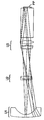
본 발명의 투사렌즈는 역초점(retrofocus) 형태로 구성되고, 도 1 내지 6 에서 도시된 바와같이 서로 공간지어져 있는 세개의 렌즈 유니트로 구성된다. 예를 들면, 상기 도에서 도시된 렌즈시스템에서, 한 유니트 내의 어느 두 렌즈 부품사이에 최대 공간은 두 유니트 사이의 최소 공간의 30%보다 적고, 여기서 유니트들 사이의 공간(즉, D12 및 D23)은 한 유니트의 최종 표면에서 다음 유니트의 첫번째 표면으로 측정된다. 이러한 약 30% 비율은 도 3의 렌즈시스템에서 일어난다. 다른 모든 렌즈시스템의 경우 상기 비는 10% 미만이다. 상기 렌즈시스템은 높은 수준의 수차-보정과 넓은 가시영역(field of view), 즉, 약 35˚보다 큰 반가시영역( half field of view)으로 특징지어진다.The projection lens of the present invention is configured in the form of retrofocus, and is composed of three lens units spaced from each other as shown in FIGS. 1 to 6. For example, in the lens system shown in the above figure, the maximum space between any two lens components in one unit is less than 30% of the minimum space between the two units, where the space between the units (i.e. D 12 and D 23 ) is measured from the final surface of one unit to the first surface of the next unit. This approximately 30% rate occurs in the lens system of FIG. For all other lens systems the ratio is less than 10%. The lens system is characterized by a high level of aberration-correction and a wide field of view, ie a half field of view larger than about 35 °.
첫번째 렌즈 유니트는 음의 배율을 가지며, 최소한 하나의 비구상 표면을 갖는 적어도 하나의 플라스틱 렌즈 부품을 가지고 있다. 바람직하기로는, 첫번째 렌즈 유니트는 하나의 플라스틱 렌즈 부품으로 구성되며, 좀더 바람직하게는, 이 싱글 렌즈 부품은 두개의 비구상 표면을 가진다. 하나의 싱글 부품은 첫번째 렌즈 유니트에 대해 더 바람직한데, 이는 첫번째 유니트의 부품이 일반적으로 시스템에서 가장 크므로, 이 부품의 크기를 축소하여 시스템의 전제 비용을 줄일 수 있기 때문이다. 예를 들면, 극도로 넓은 가시영역을 확보하기 위한 한 실시예에서, 첫번째 렌즈 유니트는 두개의 렌즈 부품을 포함할 수 있는데, 바람직하기로는 두 부품 모두 플라스틱으로 구성되며, 둘 다 두개의 비구상 표면을 가진다. 일반적으로 첫번째 렌즈 유니트 및, 특히 그 유니트의 비구상 표면은 상기 설명된 픽셀화된 패널을 사용한 렌즈시스템에서 상당히 잘 보정되어야 할 필요가 있는 시스템의 뒤틀림 보정에 기여한다. 이 뒤틀림 보정은 통상 화상에서 약 1% 보다 더욱 좋다.The first lens unit has a negative magnification and has at least one plastic lens part having at least one non-spherical surface. Preferably, the first lens unit consists of one plastic lens part, more preferably this single lens part has two non-spherical surfaces. One single component is more desirable for the first lens unit because the components of the first unit are generally the largest in the system, so that the size of these components can be reduced to reduce the overall cost of the system. For example, in one embodiment to ensure an extremely wide field of view, the first lens unit may comprise two lens parts, preferably both parts are made of plastic, both of which have two non-spherical surfaces Have In general, the first lens unit, and in particular the non-spherical surface of the unit, contributes to the distortion correction of the system which needs to be corrected considerably well in a lens system using the pixelated panel described above. This distortion correction is usually better than about 1% in the image.
두번째 렌즈 유니트 또한 음의 배율(도 1 내지 4 및 6)을 갖거나 또는 약한 양의 배율(도 5)을 갖는데, 여기서 약한 양의 배율이란 배율 P2를 의미하는 것으로서, 이는 첫번째, 두번쩨 및 세번째 렌즈 유니트(P0)의 조합 배율의 약 10% 보다 작으며, 바람직하게는 약 5%보다 더 작다. 두번째 렌즈 유니트는 적어도 하나의 컬러-보정 이중렌즈로 구성되어지며, 경우에 따라서 두개의 컬러-보정 이중렌즈(도 1 및 2)로 구성되어질 수도 있다. 발광시스템의 출력이 두번째 렌즈 유니트 부근에 있으므로, 이 유니트는 발광시스템의 출력 부근에서 발생하는 열을 견뎌낼수 있는 유리 부품만으로 구성되는 것이 바람직하다. 통상적으로 두번째 렌즈 유니트는 오프-축 컬러(off-axis color)의 보정에 기여한다.The second lens unit also has a negative magnification (FIGS. 1 to 4 and 6) or a weak positive magnification (FIG. 5), where a weak positive magnification means magnification P 2 , which is the first, second and It is smaller than about 10% of the combined magnification of the third lens unit P 0 , and preferably smaller than about 5%. The second lens unit is composed of at least one color-corrected bilens, and in some cases, may be composed of two color-corrected bilenses (Figs. 1 and 2). Since the output of the light emitting system is near the second lens unit, the unit is preferably composed of only glass parts that can withstand the heat generated near the output of the light emitting system. Typically the second lens unit contributes to the correction of off-axis color.
세번째 렌즈 유니트는 양의 배율을 가지며, 유리 부품상(도 6)에 또는 약한 플리스틱 부품상(도 1 내지 5)의 비구상 표면으로 구성된다. 여기서, 약한 플라스틱 부품은 그 절대치가 첫번째, 두번쩨 및 세번째 렌즈 유니트(P0)의 조합 배율의 약 5%보다 작은 배율(Pelement)을 가지는 것이다. 약한 플라스틱 부품은, 그것이 사용되어질 때, 보정기 렌즈 부품으로 간주되어질 수 있는데, 이는 그 목적이 시스템에 광학 배율을 제공하는 것과는 대조적으로 렌즈 수차를 보정하는 것이기 때문이다. 세번째 렌즈 유니트는 컬러-보정 이중렌즈를 포함하는 것이 바람직한데, 여기서 전체 시스템은 통상 두개의 컬러-보정 이중렌즈(두번째 렌즈 유니트에 하나 및 세번째 렌즈 유니트에 하나)를 포함하며, 세 개의 컬러-보정 이중렌즈(두번째 렌즈 유니트에 하나 및 세번째 렌즈 유니트에 하나)를 포함할 수도 있다.The third lens unit has a positive magnification and consists of a non-spherical surface on a glass piece (Fig. 6) or on a weak plastic piece (Figs. 1 to 5). Here, the weak plastic part has a magnification P element whose absolute value is less than about 5% of the combined magnification of the first, second and third lens units P 0 . Weak plastic parts, when used, can be considered as compensator lens parts because their purpose is to correct lens aberrations as opposed to providing optical magnification to the system. The third lens unit preferably comprises color-corrected bilens, wherein the overall system typically comprises two color-corrected bilenses (one for the second lens unit and one for the third lens unit) and three color-corrected lenses. It may also comprise a dual lens (one for the second lens unit and one for the third lens unit).
첫번째와 세번째 렌즈 유니트의 배율의 크기는 통상 유사하며, 각각은 두번째 렌즈 유니트의 배율 크기보다 상당히 더 크다.The magnitudes of the magnifications of the first and third lens units are usually similar, each of which is considerably larger than the magnification of the second lens unit.
전술한 바와 같이, 상기 발명의 투사렌즈는 불투열처리되어서, 특히 시스템의 역초점길이를 포함하는 시스템의 광학적 특성은 투사렌즈가 실내온도에서 작동온도까지 가열되었을때 크게 변하지 않는다. 더 상세하게 설명하자면, 역초점길이의 변화는 시스템의 변조 전환 기능(modulation transfer function; MTF)을 실질적으로 변화시키는 양보다 더 적은 것이 바람직하다. 예를들면, 변조 전환 기능(MTF)의 변화는 약 5% 보다 작아야 한다. 후술된 상세한 실시예에서, 이 변조 전환 기능(MTF)의 특징은 약 0.1밀리미터보다 작은 역초점길이의 변화와 일치한다. 렌즈 초점의 바람직한 열적 안정화는 플라스틱 렌즈 부품의 선택 및 배치를 통해 얻어진다.As mentioned above, the projection lens of the invention is opaque, so that the optical characteristics of the system, including the reverse focal length of the system, do not change significantly when the projection lens is heated from room temperature to operating temperature. More specifically, it is desirable that the change in reverse focal length be less than the amount that substantially changes the modulation transfer function (MTF) of the system. For example, the change in modulation switching function (MTF) should be less than about 5%. In the detailed embodiment described below, the characteristic of this modulation switching function (MTF) is consistent with a change in the reverse focal length of less than about 0.1 millimeters. Desirable thermal stabilization of the lens focus is obtained through the selection and placement of plastic lens parts.
통상적으로, 플라스틱 렌즈 부품의 사용은 플라스틱 광학 재료의 굴절률이 온도에 민감하게 변화하는 약점을 가진다. 또한 크기의 변화, 즉, 온도에 따라 플라스틱 광학 재료가 팽창 또는 수축한다. 일반적으로 이 후자의 영향이 굴절률에 있어서의 변화보다 덜 중요하다.Typically, the use of plastic lens parts has the disadvantage that the refractive index of the plastic optical material changes sensitive to temperature. In addition, the plastic optical material expands or contracts according to a change in size, that is, a temperature. In general, this latter effect is less important than the change in refractive index.
만일 렌즈에 낮은 배율의 플라스틱 부품만을 사용한다면, 플라스틱 광학성의 열적 변화와 플라스틱 또는 알루미늄으로 된 시스템의 기계 성분들(예를들면, 열적으로 발생한 초점 변화의 중요한 기계상의 원인이 되는 렌즈 배럴(barrel))에서의 열적 변화사이에서 균형을 얻을 수 있다. 하나의 고안에서 광학적 플라스틱의 비제한된 사용, 즉 적어도 몇몇은 비교적 높은 배율의 플라스틱 렌즈 부품을 사용함으로써 상기 플라스틱 렌즈 부품이 쉽게 주조될 수 있기 때문에, 비구상 표면이 특별한 렌즈 고안의 성능을 극대화하는데 사용되어질 수 있다는 점에서 잇점이 있다. 또한 비교적 높은 배율의 플라스틱 부품의 사용은 전체적으로 더 적은 비용을 갖는 렌즈를 생산하게 한다.If only low-magnification plastic parts are used for the lens, the lens barrel is a significant mechanical cause of thermal changes in plastic optics and mechanical components of the plastic or aluminum system (eg thermal focus shifts). There is a balance between thermal changes in. In one design, the non-spherical surface may be used to maximize the performance of a particular lens design, since the non-limiting use of optical plastic, ie at least some of the plastic lens parts can be easily cast by using a relatively high magnification of plastic lens parts. There is an advantage in that it can. The use of plastic parts of relatively high magnification also allows the production of lenses with a lower overall cost.
만일 최종적인 플라스틱 광학 배율이 상당하다면, 불투열화가 수행되어질 필요가 있거나 또는 실내온도에서 그 작동온도까지 렌즈의 온도가 변화함에 따라 렌즈의 초점도 상당히 변화할 것이다. 특히 화면까지 많은 양의 빛을 투과시켜야만 하며, 실내온도보다 상당히 높은 작동온도를 갖는 투광기(projector)에 있어서 그러하다.If the final plastic optical magnification is significant, the focus of the lens will change considerably as the deterioration needs to be performed or as the temperature of the lens changes from room temperature to its operating temperature. In particular, a large amount of light must be transmitted to the screen, such as in a projector having an operating temperature considerably higher than the room temperature.
상기 발명의 투사렌즈에 대하여, 불투열화는 플라스틱 렌즈 부품의 한계광선높이(marginal ray heights)뿐만 아니라, 위치와 배율을 고려함으로서 얻어진다For the projection lens of the present invention, opacity is obtained by considering not only the marginal ray heights of the plastic lens parts but also the position and magnification.
상기 부품이 견뎌낼 온도 변화량 및 부품의 굴절률에 발생하는 변화때문에 플라스틱 렌즈 부품의 위치가 중요하다. 통상적으로, 빛원 또는 빛원의 화상에 근접해 있는 부품들은 온도 변화에 더 크게 영향받는다. 사실상, 빛원 및 그에 관련된 발광 소자 작동으로 투사렌즈가 위치한 지역의 온도 분포를 측정하며, 상기 측정치는 투사렌즈의 고안에 사용된다.The position of the plastic lens part is important because of the amount of change in temperature and the change in the refractive index of the part that the part will withstand. Typically, the light source or components in close proximity to the image of the light source are more affected by temperature changes. In fact, the operation of the light source and its associated light emitting element measures the temperature distribution of the area where the projection lens is located, which is used in the design of the projection lens.
주어진 열적 변화에 대해, 특별한 플라스틱 렌즈 부품에서 한계광선높이는 렌즈의 전체 열적 안정성에 대하여 부품의 굴절률의 변화가 상당할 것인지 아닌지를를 결정한다. 통상적으로, 한계광선높이가 작은 부품들은 한계광선높이가 큰 부품들에 비해 시스템의 전체 열적 안정성에 미치는 효과가 더 작다.For a given thermal change, the marginal ray height in a particular plastic lens part determines whether the change in the refractive index of the part will be significant or not over the entire thermal stability of the lens. Typically, parts with a lower limit beam height have a smaller effect on the overall thermal stability of the system than parts with a high limit beam height.
전술한 고려사항에 기초하여, 상기 발명의 투사렌즈의 불투열화는 (1)한계 광선높이가 큰 위치에서 낮은 배율의 플라스틱 렌즈 부품의 사용, (2)한계광선높이가 작은 위치에서 높은 배율의 플라스틱 렌즈 부품의 사용, 및 (3)발광시스템의 출력이 있는 두번째 렌즈 유니트로부터 플라스틱 부품을 분리함으로써 얻어진다.Based on the above considerations, impervious deterioration of the projection lens of the present invention can be achieved by (1) the use of low magnification plastic lens components at locations with high limit beam heights, and (2) high magnification plastic at locations with low limit beam heights. By using the lens component, and (3) separating the plastic component from the second lens unit with the output of the light emitting system.
얻어진 불투열화의 정도는 다음과 같은 전산화된 렌즈 고안 프로그램을 사용하여 바람직하게 활용된다. 첫째, 첫번째 온도 분포에서 광선 자취(ray trace)가 얻어지고, 역초점길이가 계산된다. 광선 자취는 한계광선에 대한 병렬의 광선 자취가 될 수 있다. 둘째, 두번째 온도 분포에서 같은 광선 자취가 얻어지고, 다시 역초점길이가 계산된다. 첫번째와 두번째 온도 분포는 전 렌즈에 걸쳐 일정할 필요는 없고, 통상 렌즈 부품마다 변할 수 있다. 렌즈 고안 프로그램을 사용하여 시스템의 고안이 활용되어질 때, 역초점길이는 계산된 일정한 값을 갖는다.The degree of impairment obtained is preferably utilized using the following computerized lens design program. First, a ray trace is obtained from the first temperature distribution and the reverse focal length is calculated. The ray trace can be a ray trace in parallel to the marginal ray. Second, the same ray trace is obtained at the second temperature distribution, and the reverse focal length is calculated again. The first and second temperature distributions do not have to be constant across the entire lens, but can usually vary from lens component to lens component. When the design of the system is utilized using the lens design program, the reverse focal length has a constant calculated value.
전술한 내용에서, 시스템의 온도가 변화할 때 투사렌즈 및 픽셀화된 패널에 대한 기계 접경판(mechanical mounts)이 마지막 렌즈 표면과 패널사이의 거리를 상당히 일정하게 유지시킴을 가정하고 있음을 인지해야 한다. 만일 그러한 가정이 정당화되지 않는다면, 불투열화(예를들면, 기계 접경판의 상대적 이동에 대한 측정치)를 수행하기 위해 만들어질 수 있는 다른 설비들은 그 과정이나 또는 기계상 고정되었다고 가정할 수 있는 교차거리(alternate distance)(예를 들면, 전면 렌즈 표면과 패널 사이의 거리)에 포함되어질 수 있다.In the foregoing, it should be noted that the mechanical mounts for the projection lens and the pixelated panel maintain a fairly constant distance between the last lens surface and the panel when the temperature of the system changes. do. If such assumptions are not justified, other distances that can be made to perform imperfections (eg, measurements of relative movement of the machine abutment plate) may be assumed to be fixed in the process or mechanically. (alternate distance) (eg, the distance between the front lens surface and the panel).
긴 역초점길이, 높은 컬러-보정 정도, 낮은 뒤틀림 및 낮은 온도 민감성에 덧붙여, 몇몇 적용에서는 짧은 초점길이를 갖는 투사렌즈를 얻고자 하며, 그래서 픽셀화된 패널의 배율은 적절한 수준으로 달성될 수 있다. 특히, 픽셀화된 패널이 DMD일 때 그러한 짧은 초점 길이를 갖는 렌즈가 요구되는데, 이 DMD는 통상 특징적인 용적(예를 들면,약 20밀리미터보다 작은 사선(Diagonal))을 갖는다. 도 3 내지 6의 투사렌즈는 20밀리미터보다 작은 초점길이를 가지므로, DMD에 사용하기에 적합하다. 반대로, 도 1 내지 2의 렌즈는 50밀리미터 이상의 초점길이를 가지므로, LCD에 사용하기에 더 적합하다. 도 1 내지 2의 컬러-보정은 도 3 내지 6의 컬러-보정보다 다소 좋은 경향이 있는데, 특히 픽셀 크기에 관련하여 더 좋으며, 이는 LCD(도 1 내지 2)의 픽셀 크기가 DMD(도 3 내지 6)의 픽셀 크기보다 통상 더 크기 때문이다.In addition to long reverse focal length, high color-correction degree, low distortion and low temperature sensitivity, some applications seek to obtain a projection lens with a short focal length, so that the magnification of the pixelated panel can be achieved at an appropriate level. . In particular, a lens with such a short focal length is required when the pixelated panel is a DMD, which typically has a characteristic volume (eg, a diagonal less than about 20 millimeters). The projection lenses of Figs. 3 to 6 have a focal length of less than 20 millimeters and are therefore suitable for use in DMD. In contrast, the lenses of Figs. 1 and 2 have a focal length of 50 millimeters or more, which makes them more suitable for use in LCDs. The color-correction of FIGS. 1 to 2 tends to be somewhat better than the color-complementation of FIGS. 3 to 6, especially with regard to pixel size, which means that the pixel size of the LCD (Figs. This is because it is usually larger than the pixel size of 6).
도 1 내지 6은 본 발명에 따라 제조된 다양한 투사렌즈를 도시하고 있다. 해당되는 일반적 특성 및 광학 특성은 표1 내지 6에 있다. HOYA 또는 SCHOTT라는 명칭은 렌즈시스템에 사용된 유리를 위해 사용되었다. 다른 제조자에 의해 제조된 동등한 유리도 본 발명을 실시하는데 사용될 수 있다. 산업적으로 적용가능한 재료가 플라스틱 부품을 위해 사용된다. 표에 설명된 비구상 계수(aspherical coefficient)는 하기 수학식 I에 사용된다.1 through 6 illustrate various projection lenses made in accordance with the present invention. Applicable general and optical properties are in Tables 1-6. The name HOYA or SCHOTT was used for the glass used in the lens system. Equivalent glasses made by other manufacturers can also be used to practice the present invention. Industrially applicable materials are used for plastic parts. The aspherical coefficients described in the table are used in Equation I below.
[수학식 I][Equation I]
![]()
![]()
상기 수학식에서 z는 시스템의 광학축(optical axis)으로부터 y의 거리에서의 표면 휨(sag)이고, c는 광학축에서 렌즈의 곡률(curvature)이고 k는 원추 상수(conic constant)이다.Where z is the surface sag at a distance y from the optical axis of the system, c is the curvature of the lens at the optical axis and k is the conic constant.
표에 사용된 약어는 다음과 같다.Abbreviations used in the table are as follows.
EFL: 유효초점길이(effective focal length)EFL: effective focal length
FVD: 정면 정점 길이(front vertex distance)FVD: front vertex distance
f/: f-수(f-number)f /: f-number
ENP: 긴 콘쥬게이트로부터 보여지는 입구 동공(entrance pupil)ENP: entrance pupil seen from a long conjugate
EXP: 긴 콘쥬게이트로부터 보여지는 출구 동공(exit pupil)EXP: exit pupil as seen from the long conjugate
BRL: 배럴길이(barrel length)BRL: barrel length
OBJ HT: 대상물 높이(object height)OBJ HT: object height
MAG: 배율(magnification)MAG: magnification
STOP: 구경 조리개 위치(location of aperture stop)STOP: location of aperture stop
IMD: 화상거리(image distance)IMD: image distance
OBD: 대상물 거리(object distance)OBD: object distance
OVL: 전체길이(overall length)OVL: overall length
표에서 다양한 표면과 관련한 표시 "a"는 비구상 표면, 즉 상기 수학식에서 D, E, F, G, H 또는 J중 최소한 하나는 0이 아닌 표면을 의미한다. 표시 "c"는 상기 수학식에서 K값이 0이 아닌 원뿔 표면을 의미한다. 표에 있는 모든 수치는 밀리미터이다. 표는 도면에서 빛이 왼쪽에서 오른쪽으로 간다는 가정하에 기재되었다. 실질적으로, 화면은 왼쪽에 있을 것이고 빛은 오른쪽에서 왼쪽으로 갈 것이다. 픽셀화된 패널은 상기 도에서 "PP" 표시된다.The designation “a” in relation to various surfaces in the table means non-spherical surfaces, ie at least one of D, E, F, G, H or J in the above formula is a non-zero surface. The designation "c" means a cone surface in which the K value is not zero in the above equation. All figures in the table are in millimeters. The table is described on the assumption that the light goes from left to right in the figure. In effect, the screen will be on the left and the light will go from right to left. Pixelated panels are marked "PP" in the figure above.
표 1 및 2에서, 첫번째 렌즈 유니트(U1)는 표면 1 내지 2로 구성되고 두번째 렌즈 유니트(U2)는 표면 3 내지 10으로 구성되며, 세번째 렌즈 유니트(U3)는 표면 11 내지 17로 구성된다. 표면 18 내지 19는 렌즈시스템의 후면 말단에서 유리판(예를 들면, 보호판)에서 나타난다. 그것은 렌즈시스템의 일부가 아니며, 그것이 표 1 및 2의 일차적 성질 계산에 포함될지라도 표 7 및 8에 설명된 렌즈 성질의 요약에 포함되지 않는다.In Tables 1 and 2, the first lens unit U 1 consists of surfaces 1 to 2, the second lens unit U 2 consists of surfaces 3 to 10, and the third lens unit U 3 consists of surfaces 11 to 17. It is composed. Surfaces 18-19 appear on a glass plate (eg a protective plate) at the rear end of the lens system. It is not part of the lens system, and although it is included in the primary property calculations of Tables 1 and 2, it is not included in the summary of the lens properties described in Tables 7 and 8.
표 3에서, 첫번째 렌즈 유니트(U1)는 표면 1 내지 4로 구성되고 두번째 렌즈 유니트(U2)는 표면 5 내지 7으로 구성되며, 세번째 렌즈 유니트(U3)는 표면 9 내지 15로 구성된다. 표면 16 내지 18은 프리즘에 나타나고 렌즈시스템의 후면 말단에 위치하는 DMD 성분들과 관련이 있다. 이 성분들은 렌즈시스템의 일부가 아니며, 그것이 표 3의 일차적 성질 계산에 포함될지라도 표 7 및 8에 설명된 렌즈 성질의 요약에 포함되지 않는다.In Table 3, the first lens unit U 1 is composed of surfaces 1 to 4, the second lens unit U 2 is composed of surfaces 5 to 7, and the third lens unit U 3 is composed of surfaces 9 to 15. . Surfaces 16-18 relate to DMD components that appear in the prism and are located at the rear end of the lens system. These components are not part of the lens system and are not included in the summary of lens properties described in Tables 7 and 8, although they are included in the primary property calculations of Table 3.
표 4 내지 5에서, 첫번째 렌즈 유니트(U1)는 표면 1 내지 2로 구성되고 두 번째 렌즈 유니트(U2)는 표면 3 내지 5으로 구성되며, 세번째 렌즈 유니트(U3)는 표면 7 내지 13로 구성된다. 표 3에서와 같이, 표면 14 내지 16은 렌즈시스템의 뒤쪽 말단에 위치하는 DMD 성분들을 나타나며, 이것은 표 7 및 8에 설명된 렌즈 성질의 요약에 포함되지 않고 표 4 내지 5의 일차 성질 계산에 포함된다.In Tables 4 to 5, the first lens unit U 1 consists of surfaces 1 to 2 and the second lens unit U 2 consists of surfaces 3 to 5, and the third lens unit U 3 comprises surfaces 7 to 13. It consists of. As in Table 3, surfaces 14-16 represent DMD components located at the rear end of the lens system, which are not included in the summary of lens properties described in Tables 7 and 8, but included in the primary property calculations of Tables 4-5. do.
표 6에서, 첫번째 렌즈 유니트(U1)는 표면 1 내지 2로 구성되고 두번째 렌즈 유니트(U2)는 표면 3 내지 5으로 구성되며, 세번째 렌즈 유니트(U3)는 표면 7 내지 11로 구성된다. 표 3 내지 5에서와 같이, 표면 12 내지 14는 DMD 성분들이며, 이것은 표 7 및 8에 포함되지 않고 표 6의 일차 성질 계산에 포함된다.In Table 6, the first lens unit U 1 consists of surfaces 1 to 2, the second lens unit U 2 consists of surfaces 3 to 5, and the third lens unit U 3 consists of surfaces 7 to 11. . As in Tables 3 to 5, Surfaces 12 to 14 are DMD components, which are not included in Tables 7 and 8 and are included in the primary property calculations of Table 6.
상기 설명된 바와 같이, 도 1 및 2의 투사렌즈는 미합중국 특허 제 5,313,330(베텐스키)의 반구경 조리개(pseudo-aperture stop)/입구 동공(entrance pupil) 기술을 이용하여 고안되어졌다. 표 1 및 2의 표면 20은 반구경 조리개를 구성한다. 그 위치는 발광시스템의 출력 위치와 일치한다. "가변 공간(Variable Spaces)"로 명명된 보충표에서 볼수 있듯이, 반구경 조리개에서 픽셀화된 패널까지의 거리, 즉 "화상거리(Image Distance)"는 투사렌즈 시스템의 모든 초점위치(배율)에 대해 필수적으로 일정해야 한다.As described above, the projection lenses of FIGS. 1 and 2 were designed using the pseudo-aperture stop / entrance pupil technique of US Pat. No. 5,313,330 (Bettensky). Surface 20 of Tables 1 and 2 constitutes a semi-diameter aperture. The position coincides with the output position of the light emitting system. As can be seen in the supplementary table named "Variable Spaces", the distance from the semi-radius aperture to the pixelated panel, or "Image Distance," is used for all focal positions (magnifications) of the projection lens system. It must be constant.
또한 상기 설명된 바와 같이, 도 1 및 2의 투사렌즈는 픽셀화된 패널에 대하여 첫번째 렌즈 유니트가 고정되도록 지지하고 패널에 관계한 하나의 그룹으로서 두번째 및 세번째 유니트를 움직임으로써 초점을 맞출 수 있다. 전체 투사렌즈가 선택적으로 이동될 수 있으므로, 첫번째 렌즈 유니트가 그 일정한 자리에서 뒤로 옮겨졌다. 표 1 및 2에서 보여지는 바와 같이, 두번째 및 세번째 렌즈 유니트의 자리옮김은 5 내지 10밀리미터의 거리를 통하여 약 6배의 배율 변화를 야기시킨다. 도 3 내지 6의 투사렌즈는 픽셀화된 패널과 관련있는 전체 렌즈를 옮김으로써 초점을 맞출 수 있다.As also described above, the projection lenses of FIGS. 1 and 2 can be focused by supporting the first lens unit to be fixed relative to the pixelated panel and moving the second and third units as one group relative to the panel. Since the entire projection lens can be moved selectively, the first lens unit has been moved back from its fixed position. As shown in Tables 1 and 2, the displacement of the second and third lens units causes about 6 times magnification change over a distance of 5 to 10 millimeters. The projection lenses of FIGS. 3 to 6 can be focused by moving the entire lens associated with the pixelated panel.
표 7 및 8은 상기 발명의 투사시스템의 다양한 성질을 요약하고 있다. 상기 표에서 나열된 값들은 첫번째, 두번째 및 세번째 렌즈 유니트에 대한 것이고 표 1내지 6에서 보여지는 이들 유니트들 이후의 광학 부품들을 포함하지 않는다. BFL값은 시스템의 긴 콘쥬게이트사이의 무한대에서 대상물에 대해 계산된 것이다. 표 7의 EPD값은 이 EPD값이 "가변 공간" 보충표가 있는 표 1 및 2를 제외하고 그 이전 표의 EXP값과 일치한다는 것을 주의해야 한다.Tables 7 and 8 summarize the various properties of the projection system of the invention. The values listed in the table above are for the first, second and third lens units and do not include the optical components after these units shown in Tables 1-6. The BFL value is calculated for the object at infinity between the long conjugates of the system. It should be noted that the EPD values in Table 7 correspond to the EXP values in the previous table, except for Tables 1 and 2 with "variable space" supplemental tables.
표 8에서 보여지는 바와 같이, 렌즈시스템 1내지 6의 각각은 상기 설명된 한정(1)에서 (5)를 만족시킨다. 부가하여, 이 표는 D12 대 D23 의 비율이 본 발명의 렌즈시스템에서 다음과 같은 범위에 있음을 보여준다:As shown in Table 8, each of the lens systems 1 to 6 satisfies (5) in the limitation (1) described above. In addition, this table shows that the ratio of D 12 to D 23 is in the following range in the lens system of the present invention:
1.0 < D12/D23 < 2.51.0 <D 12 / D 23 <2.5
본 발명의 실시예가 기술되고 예시되었으나 본 발명의 범주를 벋어나지 않고 전술한 것으로부터 본 발명에 속하는 기술분야에서 통상의 지식을 가진자는 다양하게 변형할 수 있을 것이다.Although embodiments of the present invention have been described and illustrated, those skilled in the art to which the present invention pertains may make various modifications from the foregoing without departing from the scope of the present invention.


전술한 바와 같이, 본 발명의 투사렌즈는 액정 디스플레이(LCD) 또는 DMD와 같은 픽셀로 구성된 대상물의 화상을 형성하는데 우수한 특성을 갖는다.As described above, the projection lens of the present invention has excellent characteristics in forming an image of an object composed of pixels such as a liquid crystal display (LCD) or a DMD.
도 1-6은 상기 발명에 따라 고안된 투사렌즈의 도식적인 측면도이다.1-6 are schematic side views of a projection lens designed in accordance with the invention.
도 7은 본 발명의 투사렌즈가 사용되어질수 있는 전체 투사렌즈 시스템을 보여주는 도식도이다.7 is a schematic diagram showing an overall projection lens system in which the projection lens of the present invention may be used.
Claims (26)
Applications Claiming Priority (2)
| Application Number | Priority Date | Filing Date | Title |
|---|---|---|---|
| US1832596P | 1996-05-24 | 1996-05-24 | |
| US60/018,325 | 1996-05-24 |
Publications (2)
| Publication Number | Publication Date |
|---|---|
| KR970075961A KR970075961A (en) | 1997-12-10 |
| KR100465099B1 true KR100465099B1 (en) | 2005-06-17 |
Family
ID=21787364
Family Applications (1)
| Application Number | Title | Priority Date | Filing Date |
|---|---|---|---|
| KR1019970021458A KR100465099B1 (en) | 1996-05-24 | 1997-05-24 | Projection lens with large reverse focal length to focal length ratio |
Country Status (7)
| Country | Link |
|---|---|
| US (2) | US5870228A (en) |
| EP (1) | EP0809407B1 (en) |
| JP (1) | JPH10142503A (en) |
| KR (1) | KR100465099B1 (en) |
| CN (1) | CN1098464C (en) |
| DE (1) | DE69723772T2 (en) |
| TW (1) | TW328114B (en) |
Families Citing this family (88)
| Publication number | Priority date | Publication date | Assignee | Title |
|---|---|---|---|---|
| US6094311A (en) * | 1996-04-29 | 2000-07-25 | U.S. Precision Lens Inc. | LCD projection lens |
| US5870228A (en) * | 1996-05-24 | 1999-02-09 | U.S. Precision Lens Inc. | Projection lenses having larger back focal length to focal length ratios |
| US5969874A (en) * | 1996-05-30 | 1999-10-19 | U.S. Precision Lens Incorporated | Long focal length projection lenses |
| US5991089A (en) * | 1997-01-31 | 1999-11-23 | U.S. Precision Lens Inc. | Long focal length projection lenses for use with large pixelized panels |
| US5900987A (en) * | 1997-02-13 | 1999-05-04 | U.S. Precision Lens Inc | Zoom projection lenses for use with pixelized panels |
| US6317171B1 (en) * | 1997-10-21 | 2001-11-13 | Texas Instruments Incorporated | Rear-screen projection television with spatial light modulator and positionable anamorphic lens |
| WO1999026090A1 (en) | 1997-11-13 | 1999-05-27 | U.S. Precision Lens Incorporated | Wide field of view projection lenses for compact projection lens systems employing pixelized panels |
| JPH11305117A (en) * | 1998-04-24 | 1999-11-05 | Sony Corp | Projection lens and method for adjusting focus of projection lens |
| US6301057B1 (en) | 1999-02-02 | 2001-10-09 | Corning Precision Lens | Long focal length projection lenses |
| JP4232269B2 (en) | 1999-04-20 | 2009-03-04 | コニカミノルタオプト株式会社 | Projection optical system |
| US6195209B1 (en) | 1999-05-04 | 2001-02-27 | U.S. Precision Lens Incorporated | Projection lenses having reduced lateral color for use with pixelized panels |
| US6231195B1 (en) | 1999-05-20 | 2001-05-15 | Interscience, Inc. | Large-aperture, digital micromirror array-based imaging system |
| DE69930398T2 (en) * | 1999-09-20 | 2006-10-19 | Nikon Corp. | Exposure system with a parallel link mechanism and exposure method |
| US6215597B1 (en) | 1999-11-17 | 2001-04-10 | Duncan Technologies, Inc. | Apparatus for forming a plurality of subimages having different characteristics |
| JP4016576B2 (en) | 2000-07-14 | 2007-12-05 | 株式会社日立製作所 | Projection lens device and projection-type image display device |
| DE10058173A1 (en) | 2000-11-22 | 2002-05-23 | Jos Schneider Optische Werke G | Projection objective lens arrangement e.g. for movie-theater projection, has diaphragm arranged between second lens and third lens element |
| US6563650B2 (en) | 2001-01-17 | 2003-05-13 | 3M Innovative Properties Company | Compact, telecentric projection lenses for use with pixelized panels |
| US6476974B1 (en) | 2001-02-28 | 2002-11-05 | Corning Precision Lens Incorporated | Projection lenses for use with reflective pixelized panels |
| US6515801B1 (en) | 2001-12-21 | 2003-02-04 | Koninklijke Philips Electronics N.V. | Lateral color compensation for projection displays |
| US6853493B2 (en) | 2003-01-07 | 2005-02-08 | 3M Innovative Properties Company | Folded, telecentric projection lenses for use with pixelized panels |
| US7684134B2 (en) * | 2003-01-21 | 2010-03-23 | The General Hospital Corporation | Microscope objectives |
| US6765731B1 (en) * | 2003-03-28 | 2004-07-20 | 3M Innovative Properties Company | Low element count projection lenses for use with pixelized panels |
| US7126767B2 (en) | 2003-12-05 | 2006-10-24 | 3M Innovative Properties Company | Wide-angle projection lens for front projection display systems |
| AU2004297974A1 (en) * | 2003-12-05 | 2005-06-23 | 3M Innovative Properties Company | Wide-angle projection lens and optical engine for a projection display device |
| US7123426B2 (en) * | 2003-12-05 | 2006-10-17 | 3M Innovative Properties Company | Projection lens and display device |
| US7271964B2 (en) * | 2003-12-05 | 2007-09-18 | 3M Innovative Properties Company | Projection display device for multimedia and wall display systems |
| JP2005309251A (en) * | 2004-04-23 | 2005-11-04 | Sekinosu Kk | Projection lens |
| JP2005331649A (en) * | 2004-05-19 | 2005-12-02 | Nitto Kogaku Kk | Lens system for projection and projector apparatus |
| US20060285090A1 (en) * | 2004-12-03 | 2006-12-21 | 3M Innovative Properties Company | Projection lens and portable display device for gaming and other applications |
| US7342723B2 (en) * | 2004-12-03 | 2008-03-11 | 3M Innovative Properties Company | Projection lens and portable display device for gaming and other applications |
| US7173777B1 (en) | 2006-02-14 | 2007-02-06 | 3M Innovative Properties Company | Projection lens and display device for multimedia and other systems |
| US7167316B1 (en) | 2005-07-29 | 2007-01-23 | Hewlett-Packard Development Company, L.P. | Projection lens assembly |
| US7438423B2 (en) * | 2005-08-29 | 2008-10-21 | 3M Innovative Properties Company | Illumination system and projection system incorporating same |
| GB0522968D0 (en) | 2005-11-11 | 2005-12-21 | Popovich Milan M | Holographic illumination device |
| US7411735B2 (en) * | 2005-12-06 | 2008-08-12 | 3M Innovative Property Company | Illumination system incorporating collimated light source |
| TWI287686B (en) * | 2005-12-30 | 2007-10-01 | Ind Tech Res Inst | Light-beam generator and projecting system having the same |
| GB0718706D0 (en) | 2007-09-25 | 2007-11-07 | Creative Physics Ltd | Method and apparatus for reducing laser speckle |
| US20080068565A1 (en) * | 2006-09-12 | 2008-03-20 | Ods Co., Ltd. | Micro display device |
| US7857463B2 (en) * | 2007-03-29 | 2010-12-28 | Texas Instruments Incorporated | Optical system for a thin, low-chin, projection television |
| US20090257117A1 (en) * | 2008-04-09 | 2009-10-15 | Tomoyuki Baba | Projection optical system and projection type display using the same |
| US7988306B2 (en) * | 2008-10-02 | 2011-08-02 | Eastman Kodak Company | Afocal attachment for projection lens |
| US9335604B2 (en) | 2013-12-11 | 2016-05-10 | Milan Momcilo Popovich | Holographic waveguide display |
| US11726332B2 (en) | 2009-04-27 | 2023-08-15 | Digilens Inc. | Diffractive projection apparatus |
| WO2011042711A2 (en) | 2009-10-09 | 2011-04-14 | Milan Momcilo Popovich | Compact edge illuminated diffractive display |
| US11204540B2 (en) | 2009-10-09 | 2021-12-21 | Digilens Inc. | Diffractive waveguide providing a retinal image |
| CN103080808B (en) | 2010-08-27 | 2015-07-01 | 3M创新有限公司 | Wide-angle projection lens for projection display systems |
| US8995062B2 (en) | 2010-08-27 | 2015-03-31 | 3M Innovative Properties Company | Projection lens for projection display systems |
| US9274349B2 (en) | 2011-04-07 | 2016-03-01 | Digilens Inc. | Laser despeckler based on angular diversity |
| CN102231039B (en) * | 2011-06-29 | 2013-03-06 | 苏州佳世达光电有限公司 | Projection device |
| WO2016020630A2 (en) | 2014-08-08 | 2016-02-11 | Milan Momcilo Popovich | Waveguide laser illuminator incorporating a despeckler |
| EP2995986B1 (en) | 2011-08-24 | 2017-04-12 | Rockwell Collins, Inc. | Data display |
| US10670876B2 (en) | 2011-08-24 | 2020-06-02 | Digilens Inc. | Waveguide laser illuminator incorporating a despeckler |
| US20150010265A1 (en) | 2012-01-06 | 2015-01-08 | Milan, Momcilo POPOVICH | Contact image sensor using switchable bragg gratings |
| CN106125308B (en) | 2012-04-25 | 2019-10-25 | 罗克韦尔柯林斯公司 | Device and method for displaying images |
| WO2013167864A1 (en) | 2012-05-11 | 2013-11-14 | Milan Momcilo Popovich | Apparatus for eye tracking |
| US9933684B2 (en) | 2012-11-16 | 2018-04-03 | Rockwell Collins, Inc. | Transparent waveguide display providing upper and lower fields of view having a specific light output aperture configuration |
| US10209517B2 (en) | 2013-05-20 | 2019-02-19 | Digilens, Inc. | Holographic waveguide eye tracker |
| US9727772B2 (en) | 2013-07-31 | 2017-08-08 | Digilens, Inc. | Method and apparatus for contact image sensing |
| US10359736B2 (en) | 2014-08-08 | 2019-07-23 | Digilens Inc. | Method for holographic mastering and replication |
| WO2016042283A1 (en) | 2014-09-19 | 2016-03-24 | Milan Momcilo Popovich | Method and apparatus for generating input images for holographic waveguide displays |
| WO2016046514A1 (en) | 2014-09-26 | 2016-03-31 | LOKOVIC, Kimberly, Sun | Holographic waveguide opticaltracker |
| EP3245444B1 (en) | 2015-01-12 | 2021-09-08 | DigiLens Inc. | Environmentally isolated waveguide display |
| EP3245551B1 (en) | 2015-01-12 | 2019-09-18 | DigiLens Inc. | Waveguide light field displays |
| JP6867947B2 (en) | 2015-01-20 | 2021-05-12 | ディジレンズ インコーポレイテッド | Holographic waveguide rider |
| US9632226B2 (en) | 2015-02-12 | 2017-04-25 | Digilens Inc. | Waveguide grating device |
| WO2016146963A1 (en) | 2015-03-16 | 2016-09-22 | Popovich, Milan, Momcilo | Waveguide device incorporating a light pipe |
| US10591756B2 (en) | 2015-03-31 | 2020-03-17 | Digilens Inc. | Method and apparatus for contact image sensing |
| JP6598269B2 (en) | 2015-10-05 | 2019-10-30 | ディジレンズ インコーポレイテッド | Waveguide display |
| WO2017134412A1 (en) | 2016-02-04 | 2017-08-10 | Milan Momcilo Popovich | Holographic waveguide optical tracker |
| WO2017162999A1 (en) | 2016-03-24 | 2017-09-28 | Popovich Milan Momcilo | Method and apparatus for providing a polarization selective holographic waveguide device |
| US10890707B2 (en) | 2016-04-11 | 2021-01-12 | Digilens Inc. | Holographic waveguide apparatus for structured light projection |
| WO2018102834A2 (en) | 2016-12-02 | 2018-06-07 | Digilens, Inc. | Waveguide device with uniform output illumination |
| WO2018129398A1 (en) | 2017-01-05 | 2018-07-12 | Digilens, Inc. | Wearable heads up displays |
| WO2019079350A2 (en) | 2017-10-16 | 2019-04-25 | Digilens, Inc. | Systems and methods for multiplying the image resolution of a pixelated display |
| US10914950B2 (en) | 2018-01-08 | 2021-02-09 | Digilens Inc. | Waveguide architectures and related methods of manufacturing |
| CN111566571B (en) | 2018-01-08 | 2022-05-13 | 迪吉伦斯公司 | System and method for holographic grating high throughput recording in waveguide cells |
| CN111615655B (en) | 2018-01-08 | 2023-03-21 | 迪吉伦斯公司 | System and method for manufacturing waveguide unit |
| KR20200133265A (en) | 2018-03-16 | 2020-11-26 | 디지렌즈 인코포레이티드. | Holographic waveguide with integrated birefringence control and method of manufacturing the same |
| WO2020023779A1 (en) | 2018-07-25 | 2020-01-30 | Digilens Inc. | Systems and methods for fabricating a multilayer optical structure |
| WO2020149956A1 (en) | 2019-01-14 | 2020-07-23 | Digilens Inc. | Holographic waveguide display with light control layer |
| US20200264378A1 (en) | 2019-02-15 | 2020-08-20 | Digilens Inc. | Methods and Apparatuses for Providing a Holographic Waveguide Display Using Integrated Gratings |
| US20220283377A1 (en) | 2019-02-15 | 2022-09-08 | Digilens Inc. | Wide Angle Waveguide Display |
| JP2022525165A (en) | 2019-03-12 | 2022-05-11 | ディジレンズ インコーポレイテッド | Holographic Waveguide Backlights and Related Manufacturing Methods |
| EP3980825A4 (en) | 2019-06-07 | 2023-05-03 | Digilens Inc. | Waveguides incorporating transmissive and reflective gratings and related methods of manufacturing |
| EP4004646A4 (en) | 2019-07-29 | 2023-09-06 | Digilens Inc. | Methods and apparatus for multiplying the image resolution and field-of-view of a pixelated display |
| EP4022370A4 (en) | 2019-08-29 | 2023-08-30 | Digilens Inc. | Evacuating bragg gratings and methods of manufacturing |
| JP2024502255A (en) | 2020-12-21 | 2024-01-18 | ディジレンズ インコーポレイテッド | Eye glow suppression in waveguide-based displays |
| WO2022187870A1 (en) | 2021-03-05 | 2022-09-09 | Digilens Inc. | Evacuated periotic structures and methods of manufacturing |
Family Cites Families (42)
| Publication number | Priority date | Publication date | Assignee | Title |
|---|---|---|---|---|
| US2468564A (en) * | 1946-01-12 | 1949-04-26 | American Optical Corp | Optical objective system with spherical aberration correction means |
| US4189211A (en) * | 1978-01-03 | 1980-02-19 | Kollmorgen Corporation | Wide angle telecentric projection lens assembly |
| US4526442A (en) * | 1981-01-28 | 1985-07-02 | U.S. Precision Lens, Inc. | Compact projection lens |
| US4425028A (en) * | 1981-12-28 | 1984-01-10 | Hughes Aircraft Company | High efficiency optical tank for three color liquid crystal light valve image projection with color selective prepolarization and single projection lens |
| US4461542A (en) * | 1981-12-28 | 1984-07-24 | Hughes Aircraft Company | High efficiency optical tank for three color liquid crystal light valve image projection with color selective prepolarization |
| JPS58125007A (en) * | 1982-01-20 | 1983-07-25 | Matsushita Electric Ind Co Ltd | Projection lens |
| JPS6049311A (en) * | 1983-08-29 | 1985-03-18 | Nippon Kogaku Kk <Nikon> | Projection lens |
| JPH073504B2 (en) * | 1984-12-05 | 1995-01-18 | 松下電器産業株式会社 | Projection lens |
| NL8500454A (en) * | 1985-02-18 | 1986-09-16 | Philips Nv | PROJECTIVE SYSTEM. |
| JPS61205909A (en) * | 1985-03-11 | 1986-09-12 | Hitachi Ltd | Optical system for prjection type television |
| US4815831A (en) * | 1985-07-11 | 1989-03-28 | U.S. Precision Lens, Incorporated | Projection lens with color correction |
| JP2679016B2 (en) * | 1986-12-08 | 1997-11-19 | ミノルタ株式会社 | Zoom lens system for finite distance |
| US4826311A (en) * | 1987-07-24 | 1989-05-02 | Hughes Aircraft Company | Prism assembly with three periscopes and projection lenses for a single light valve full-color projector |
| US4989954A (en) * | 1987-10-09 | 1991-02-05 | Matsushita Electric Industrial Co., Ltd. | Projection type liquid cyrstal display device |
| JP2635404B2 (en) * | 1989-03-23 | 1997-07-30 | 松下電器産業株式会社 | Projection display device |
| US4963007A (en) * | 1989-09-05 | 1990-10-16 | U.S. Precision Lens, Inc. | Color corrected projection lens |
| JP2801293B2 (en) * | 1989-10-03 | 1998-09-21 | キヤノン株式会社 | Zoom lens |
| US5119117A (en) * | 1990-06-11 | 1992-06-02 | Itt Corporation | Low secondary color spectrum triplett |
| US5278698A (en) * | 1990-07-06 | 1994-01-11 | Asahi Kogaku Kogyo Kabushiki Kaisha | Magnifying projecting lens |
| JPH04174812A (en) * | 1990-11-08 | 1992-06-23 | Canon Inc | Retro-focus type lens |
| US5200861A (en) * | 1991-09-27 | 1993-04-06 | U.S. Precision Lens Incorporated | Lens systems |
| JP3021127B2 (en) * | 1991-10-23 | 2000-03-15 | キヤノン株式会社 | Retro focus lens |
| US5390048A (en) * | 1991-12-02 | 1995-02-14 | Matsushita Electric Industrial Co., Ltd. | Projection lens assembly and projection display apparatus |
| US5218480A (en) * | 1991-12-03 | 1993-06-08 | U.S. Precision Lens Incorporated | Retrofocus wide angle lens |
| US5442484A (en) * | 1992-01-06 | 1995-08-15 | Mitsubishi Denki Kabushiki Kaisha | Retro-focus type lens and projection-type display apparatus |
| JPH05273464A (en) * | 1992-03-27 | 1993-10-22 | Fuji Photo Optical Co Ltd | Variable focal distance lens |
| US5313330A (en) * | 1992-08-31 | 1994-05-17 | U.S. Precision Lens Incorporated | Zoom projection lens systems |
| US5309283A (en) * | 1993-03-30 | 1994-05-03 | U.S. Precision Lens Incorporated | Hybrid, color-corrected, projection TV lens system |
| JPH06317742A (en) * | 1993-05-10 | 1994-11-15 | Casio Comput Co Ltd | Projection lens |
| US5659424A (en) * | 1993-05-25 | 1997-08-19 | Hitachi, Ltd. | Projecting lens and image display device |
| JPH06347695A (en) * | 1993-06-14 | 1994-12-22 | Nikon Corp | Projection lens |
| US5455713A (en) * | 1993-06-23 | 1995-10-03 | Kreitzer; Melvyn H. | High performance, thermally-stabilized projection television lens systems |
| JP3380015B2 (en) * | 1993-11-12 | 2003-02-24 | ペンタックス株式会社 | Endoscope objective lens |
| JP3432626B2 (en) * | 1994-04-20 | 2003-08-04 | 三菱電機株式会社 | Retro focus projection lens |
| KR950033566A (en) * | 1994-05-02 | 1995-12-26 | 이헌조 | Projection lens |
| US5625495A (en) * | 1994-12-07 | 1997-04-29 | U.S. Precision Lens Inc. | Telecentric lens systems for forming an image of an object composed of pixels |
| JP3466002B2 (en) * | 1995-07-13 | 2003-11-10 | 三菱電機株式会社 | Retro focus lens |
| US5841587A (en) * | 1996-04-29 | 1998-11-24 | U.S. Precision Lens Inc. | LCD projection lens |
| US6094311A (en) * | 1996-04-29 | 2000-07-25 | U.S. Precision Lens Inc. | LCD projection lens |
| US5870228A (en) * | 1996-05-24 | 1999-02-09 | U.S. Precision Lens Inc. | Projection lenses having larger back focal length to focal length ratios |
| DE69726352T2 (en) * | 1996-08-16 | 2004-09-09 | 3M Innovative Properties Co., St. Paul | Miniature projection zoom lens for use with pixel matrix display board |
| US5900987A (en) * | 1997-02-13 | 1999-05-04 | U.S. Precision Lens Inc | Zoom projection lenses for use with pixelized panels |
-
1997
- 1997-05-16 US US08/857,358 patent/US5870228A/en not_active Expired - Lifetime
- 1997-05-23 DE DE69723772T patent/DE69723772T2/en not_active Expired - Fee Related
- 1997-05-23 EP EP97108367A patent/EP0809407B1/en not_active Expired - Lifetime
- 1997-05-24 KR KR1019970021458A patent/KR100465099B1/en not_active IP Right Cessation
- 1997-05-26 JP JP9135559A patent/JPH10142503A/en active Pending
- 1997-05-26 CN CN97105524A patent/CN1098464C/en not_active Expired - Fee Related
- 1997-06-13 TW TW086108394A patent/TW328114B/en not_active IP Right Cessation
-
1999
- 1999-02-08 US US09/246,346 patent/US5969876A/en not_active Expired - Lifetime
Also Published As
| Publication number | Publication date |
|---|---|
| CN1180841A (en) | 1998-05-06 |
| DE69723772D1 (en) | 2003-09-04 |
| CN1098464C (en) | 2003-01-08 |
| TW328114B (en) | 1998-03-11 |
| US5870228A (en) | 1999-02-09 |
| EP0809407B1 (en) | 2003-07-30 |
| JPH10142503A (en) | 1998-05-29 |
| KR970075961A (en) | 1997-12-10 |
| EP0809407A1 (en) | 1997-11-26 |
| US5969876A (en) | 1999-10-19 |
| DE69723772T2 (en) | 2004-06-03 |
Similar Documents
| Publication | Publication Date | Title |
|---|---|---|
| KR100465099B1 (en) | Projection lens with large reverse focal length to focal length ratio | |
| US6301057B1 (en) | Long focal length projection lenses | |
| US5969874A (en) | Long focal length projection lenses | |
| US6417971B1 (en) | Zoom projection lens having a lens correction unit | |
| US5900987A (en) | Zoom projection lenses for use with pixelized panels | |
| KR100465100B1 (en) | Mini-zoom lens with pixelated panel | |
| KR100570392B1 (en) | Optical projection lens for compact projection lens system with pixel panel | |
| CN100380161C (en) | Zoom lens and image display apparatus including the zoom lens | |
| KR100600197B1 (en) | Color Corrected Projection Lens Using Diffractive Light Surface | |
| US8328369B2 (en) | Projecting zoom lens and projection type display apparatus | |
| US6141154A (en) | Focusable, color corrected, high performance projection lens systems | |
| KR20010021697A (en) | High performance projection television lens systems | |
| KR19980041716A (en) | Projection lens | |
| US7889431B2 (en) | Projection zoom lens and projection-type display apparatus | |
| JP5254146B2 (en) | Wide angle zoom lens for projection and projection display device | |
| KR20030088112A (en) | Projection lenses for use with reflective pixelized panels | |
| JPH09329740A (en) | Temperature independent lcd projection lens | |
| US8223435B2 (en) | Zoom lens for projection and projection-type display device | |
| CN109212727A (en) | Projector and projection lens | |
| CN111492294A (en) | Projection lens system and image projection apparatus | |
| US5991089A (en) | Long focal length projection lenses for use with large pixelized panels | |
| US7170691B2 (en) | Zoom lens system | |
| KR100531153B1 (en) | Projection lens used with large pixelated panel | |
| JPH03103807A (en) | Projection lens |
Legal Events
| Date | Code | Title | Description |
|---|---|---|---|
| PA0109 | Patent application |
Patent event code: PA01091R01D Comment text: Patent Application Patent event date: 19970524 |
|
| PG1501 | Laying open of application | ||
| A201 | Request for examination | ||
| PA0201 | Request for examination |
Patent event code: PA02012R01D Patent event date: 20020520 Comment text: Request for Examination of Application Patent event code: PA02011R01I Patent event date: 19970524 Comment text: Patent Application |
|
| N231 | Notification of change of applicant | ||
| PN2301 | Change of applicant |
Patent event date: 20030512 Comment text: Notification of Change of Applicant Patent event code: PN23011R01D |
|
| E902 | Notification of reason for refusal | ||
| PE0902 | Notice of grounds for rejection |
Comment text: Notification of reason for refusal Patent event date: 20040427 Patent event code: PE09021S01D |
|
| E701 | Decision to grant or registration of patent right | ||
| PE0701 | Decision of registration |
Patent event code: PE07011S01D Comment text: Decision to Grant Registration Patent event date: 20041125 |
|
| GRNT | Written decision to grant | ||
| PR0701 | Registration of establishment |
Comment text: Registration of Establishment Patent event date: 20041227 Patent event code: PR07011E01D |
|
| PR1002 | Payment of registration fee |
Payment date: 20041228 End annual number: 3 Start annual number: 1 |
|
| PG1601 | Publication of registration | ||
| FPAY | Annual fee payment |
Payment date: 20071224 Year of fee payment: 4 |
|
| PR1001 | Payment of annual fee |
Payment date: 20071224 Start annual number: 4 End annual number: 4 |
|
| LAPS | Lapse due to unpaid annual fee | ||
| PC1903 | Unpaid annual fee |
Termination category: Default of registration fee Termination date: 20091110 |