KR100335025B1 - Deflection Yoke - Google Patents
Deflection Yoke Download PDFInfo
- Publication number
- KR100335025B1 KR100335025B1 KR1019970005952A KR19970005952A KR100335025B1 KR 100335025 B1 KR100335025 B1 KR 100335025B1 KR 1019970005952 A KR1019970005952 A KR 1019970005952A KR 19970005952 A KR19970005952 A KR 19970005952A KR 100335025 B1 KR100335025 B1 KR 100335025B1
- Authority
- KR
- South Korea
- Prior art keywords
- deflection yoke
- deflection
- window
- coil
- introduction port
- Prior art date
Links
- 238000004804 winding Methods 0.000 claims abstract description 52
- 238000010894 electron beam technology Methods 0.000 claims abstract description 21
- 241000226585 Antennaria plantaginifolia Species 0.000 description 11
- 238000000034 method Methods 0.000 description 10
- 241000699666 Mus <mouse, genus> Species 0.000 description 9
- 238000010586 diagram Methods 0.000 description 6
- 238000009826 distribution Methods 0.000 description 5
- 238000004519 manufacturing process Methods 0.000 description 4
- 206010010071 Coma Diseases 0.000 description 2
- 241000699670 Mus sp. Species 0.000 description 2
- 230000002411 adverse Effects 0.000 description 1
- 239000003086 colorant Substances 0.000 description 1
- 230000000694 effects Effects 0.000 description 1
- 239000000696 magnetic material Substances 0.000 description 1
- 239000011347 resin Substances 0.000 description 1
- 229920005989 resin Polymers 0.000 description 1
- 230000003313 weakening effect Effects 0.000 description 1
Images


Classifications
-
- H—ELECTRICITY
- H01—ELECTRIC ELEMENTS
- H01J—ELECTRIC DISCHARGE TUBES OR DISCHARGE LAMPS
- H01J29/00—Details of cathode-ray tubes or of electron-beam tubes of the types covered by group H01J31/00
- H01J29/46—Arrangements of electrodes and associated parts for generating or controlling the ray or beam, e.g. electron-optical arrangement
- H01J29/70—Arrangements for deflecting ray or beam
- H01J29/72—Arrangements for deflecting ray or beam along one straight line or along two perpendicular straight lines
- H01J29/76—Deflecting by magnetic fields only
- H01J29/762—Deflecting by magnetic fields only using saddle coils or printed windings
-
- H—ELECTRICITY
- H01—ELECTRIC ELEMENTS
- H01J—ELECTRIC DISCHARGE TUBES OR DISCHARGE LAMPS
- H01J2229/00—Details of cathode ray tubes or electron beam tubes
- H01J2229/70—Electron beam control outside the vessel
- H01J2229/703—Electron beam control outside the vessel by magnetic fields
- H01J2229/7032—Conductor design and distribution
- H01J2229/7033—Winding
Abstract
본 발명은 R/B라인의 수직 미스컨버전스 및 크로스 미스컨버전스들을 저렴하게 방지할 수 있는, 전자총 방사 인-라인 전자총을 가진 칼라 CRT의 전자빔을 편향시키는 셀프 컨버전스 시스템의 향상된 편향요크를 제공한다. 편향요크는 한쌍이상의 섀들형 수평편향 코일을 포함한다. 각 섀들형 수평코일은 그 중심부에서 창에 의해 분할된 2개의 주코일부, 전방마우스를 형성하는 전방림, 후방마우스를 형성하는 후방림과, 전방 및 후방림중 하나에 바로 근접한 제1 분할권선부를 포함한다. 더나아가, 제 2분할권선부는 각각 2개의 주코일부의 후반 절반부의 2개의 주코일부에 제공된다. 제 2분할권선부는 소개구에 의해, 2부분, 창에 근접하게 위치된 제1 코일부와 창에서 떨어져 위치된 제 2코일부로 분할된다. 제 1코일부는 소개구를 형성하도록 창쪽으로 향해 구부러진 굴곡부를 갖는다.The present invention provides an improved deflection yoke of a self-convergence system that deflects an electron beam of a color CRT with an electron gun radiating in-line electron gun, which can inexpensively prevent vertical misconvergence and cross misconvergence of an R / B line. The deflection yoke includes one or more pairs of shaded horizontal deflection coils. Each of the shaded horizontal coils has two main coil portions divided by windows at the center thereof, a front rim forming a front mouse, a rear rim forming a rear mouse, and a first split winding portion immediately adjacent to one of the front and rear rims. Include. Furthermore, the second split winding portion is provided in two main coil portions of the latter half of the two main coil portions, respectively. The second split winding portion is divided into two portions, a first coil portion located close to the window and a second coil portion located away from the window, by the introduction port. The first coil portion has a bent portion that is bent toward the window to form an introduction port.
Description
본 발명은 3가지 색상의 R,G,B를 향하여 수평으로 인-라인에 배열된(인-라인의 구조로) 3개의 전자총을 갖는 칼라 음극선관에 이용되는 셀프 컨버전스 시스템의 편향요크에 관한 것으로서, 특히 편향요크의 크기와 그 제작 단가를 증가시키지 않고서도 편향요크에서 R/B(레드와 블루) 라인의 수직 미스컨버전스와 그 크로스 미스컨버전스의 개선에 관한 것이다.The present invention relates to a deflection yoke of a self-convergence system for a color cathode ray tube having three electron guns arranged in-line (in an in-line structure) horizontally toward three colors of R, G, and B. In particular, it relates to the improvement of the vertical misconvergence of the R / B (red and blue) lines and their cross misconvergence in the deflection yoke without increasing the size of the deflection yoke and its manufacturing cost.
셀프 컨버전스 시스템의 편향요크는 3개의 전자총으로부터 방출되고, 인-라인 칼라 음극선관(이하, 인-라인 칼라 CRT로 표기), 3개의 전자총을 이용하는 이미지 디스플레이용 스크린에 방사되는 3개의 전자빔의 좋은 컨버전스를 제공하기 위한 하나의 방법으로 실시되어 왔다.The deflection yoke of the self-convergence system is a good convergence of three electron beams emitted from three electron guns, radiated on an in-line color cathode ray tube (hereinafter referred to as an in-line color CRT), and a screen for image display using three electron guns. It has been practiced in one way to provide.
이러한 유형의 편향요크는 한쌍의 섀들형 수평편향 코일과 한쌍의 섀들형 수직편향 코일을 이용하여 핀쿠션의 수평 및 수직편향 자기장과 원통형 패턴들이 각각 형성되도록 설계된다.This type of deflection yoke is designed such that the horizontal and vertical deflection magnetic fields of the pincushion and the cylindrical patterns are formed using a pair of shaded horizontal deflection coils and a pair of shaded vertical deflection coils, respectively.
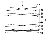
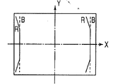
도 1(A) 및 도 1(B)를 참조하면, 본 명세서에는 셀프 컨버전스 시스템의 편향요크의 작동과 그 주요 구조가 주어져 있다.1 (A) and 1 (B), the operation of the deflection yoke of the self-convergence system and its main structure are given herein.
도 1(A)는 세로 방향(Z축)을 따라 취한, 편향요크를 장착한 종래 기술의 인-라인 칼라 CRT의 주요 구성들의 수직 단면도이고, 여기에는 한 쌍의 수평편향 코일에 의해 형성된 핀쿠션 패턴을 갖는 수평편향 자기장이 복수의 화살표로 도시되어 있고, 작은 원들은 블루, 그린, 레드 전자빔들을 각각 나타내는 참조부호 B,G,R로 도시되어 있다.Figure 1 (A) is a vertical cross-sectional view of the main components of a prior art in-line collar CRT equipped with a deflection yoke, taken along the longitudinal direction (Z axis), in which a pincushion pattern formed by a pair of horizontal deflection coils The horizontally deflected magnetic field is shown by a plurality of arrows, and the small circles are shown by reference numerals B, G and R, respectively, representing the blue, green and red electron beams.
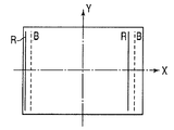
도 1(B)는 세로 방향(Z축)을 따라 취한, 편향요크를 장착한 종래 기술의 인-라인 칼라 CRT의 주요 구성들의 수직 단면도이고, 여기에는 한 쌍의 수직편향 코일에 의해 형성된 핀쿠션 패턴을 갖는 수지편향 자기장이 복수의 화살표로 도시되어 있고, 작은 원들은 블루, 그린, 레드 전자빔들을 각각 나타내는 참조부호 B,G,R로 도시되어 있다.1 (B) is a vertical cross sectional view of the main components of a prior art in-line collar CRT equipped with a deflection yoke, taken along the longitudinal direction (Z axis), in which a pincushion pattern formed by a pair of vertical deflection coils The resin deflected magnetic field is shown by a plurality of arrows, and small circles are shown by reference numerals B, G, and R, which represent blue, green, and red electron beams, respectively.
도 1(A)를 참조하면, 인-라인 칼라 CRT(8)에는, 3개의 전자총(도시 안됨)들이 인-라인 칼라 CRT(8)의 수평축(Z축)을 따라 인-라인 구조로 배열된다. 참조부호 B,G,R들은 3개의 전자총으로부터 방사되는 전자빔을 나타내는 것이다. 일반적으로,그린 빔(G)은 순서대로 배치되는 3개의 전자빔 B,G,R들중 그 중심부에 배치된다.Referring to FIG. 1A, in the in-
도 1(A)에 따르면, 일 수평편향 코일(3c)은 X축의 상측부에 위치하는 2개의 주코일부(3c,3c)를 가지고, 타 수평편향 코일(3d)은 X축의 하측부에 위치하는 2개의 주코일부(3d,3d)를 가진다. 상기 쌍의 수평편향 코일(3c,4d)은 인-라인 칼라 CRT(8)의 외부면상에 장착되어 있다.According to Fig. 1A, one horizontal deflection coil 3c has two main coil parts 3c and 3c located on the upper side of the X axis, and the other horizontal deflection coil 3d is located on the lower side of the X axis. It has two main coil parts 3d and 3d. The pair of
" 도트" 와 " X" 가 서로에 대해 대응방향으로 도 1(A)에 도시된 바와 같이, 그 방향으로 상기 쌍의 수평편향 코일(3c,3d)에 전류를 인가시키는 경우에, 핀쿠션 패턴(핀쿠션 수평 자기장으로 표기)을 갖으며, 복수의 화살표로 도시된 수평편향 자기장은 X-Y 평면상에서 상기 쌍의 수평편향 코일(3c,3d)로부터 발생하며, 칼라 CRT(8)의 세로 방향(Z축)으로 연장되어 있다.In the case where "dot " and " X " are applied to the pair of horizontal deflection coils 3c and 3d in that direction, as shown in Fig. 1A in a corresponding direction with respect to each other, the pincushion pattern ( And a horizontal deflection magnetic field, shown by a plurality of arrows, originating from the pair of horizontal deflection coils 3c and 3d on the XY plane, and in the longitudinal direction (Z axis) of the
핀쿠션 수평 자기장은 그 세기가 수직축(Y축)에 대하여 거의 대칭이며, 좌, 우방향으로 Y축으로부터 떨어진 지점에서 점차 증가하게 되는 특성을 가지고 있다.The pincushion horizontal magnetic field is characterized by its intensity being substantially symmetrical about the vertical axis (Y axis) and gradually increasing at a point away from the Y axis in the left and right directions.
이와 반대로, 도 1(B)에 따르면, 일 수직편향 코일(4c)은 Y축의 좌측부에 위치하는 2개의 주코일부(4c,4c)를 가지고, 타 수직편향 코일(4d)은 Y축의 우측부에 위치하는 2개의 주코일부(4d,4d)를 가진다. 상기 쌍의 수직편향 코일(4c,4d)은 인-라인 칼라 CRT(8)의 외부면상에 장착되어 있다.On the contrary, according to Fig. 1B, one vertical deflection coil 4c has two main coil parts 4c and 4c located on the left side of the Y axis, and the other
도 1(B)에 도시된 방향으로 상기 쌍의 수직편향 코일(4c,4d)에 전류를 인가시키는 경우에, 원통형 패턴(원통형 수평 자기장으로 표기)을 갖으며, 복수의 화살표로 도시된 수평편향 자기장은 X-Y 평면상으로부터 발생하게 된다.When a current is applied to the pair of
원통형 수직 자기장은 그 세기가 수평축(X축)에 대하여 거의 대칭이며, 상,하방향으로 X축으로부터 떨어진 지점에서 점차 증가하게 되는 특성을 가지고 있다.The cylindrical vertical magnetic field is characterized by its intensity being substantially symmetrical about the horizontal axis (X axis) and gradually increasing at a point away from the X axis in the up and down directions.
상기 쌍의 수평 및 수직편향 코일(3c,3d,4c,4d)들을 이용하여 3개의 전자빔 R,G,B들의 컨버전스를 정확하게 제어하는 방법으로는, 상기 쌍의 수평 및 수직편향 코일(3c,3d,4c,4d)에 의해 발생되며, 수평이나 수직편향 회로(도시 안됨)에 보정회로를 추가시키거나, 혹은 상기 쌍의 수평 및 수직편향 코일(3c,3d,4c,4d)의 외측부에 자기물질 부재를 제공시킴에 따라 발생되는 자기장 분포를 제어하는 방법들이 있다.As a method of accurately controlling the convergence of three electron beams R, G, and B by using the pair of horizontal and
이에 의하여, 3개의 전자총으로부터 방사된 3개의 전자빔 R,G,B들은 스크린 상에서 효과적으로 컨버전되기 위하여 제어될 수 있다.Thereby, the three electron beams R, G, B emitted from the three electron guns can be controlled to be effectively converted on the screen.
도 2는 Y축방향으로부터 보이며, 종래 기술의 한 쌍의 수평편향 코일중 하나를 나타내는 평면도이다.2 is a plan view showing one of a pair of horizontal deflection coils of the prior art, seen from the Y axis direction.
도 3은 도 2의 Z축방향에서 본 수평편향 코일의 정면도이다.3 is a front view of the horizontal deflection coil seen in the Z-axis direction of FIG. 2.
본 명세서에는 한 쌍의 섀들형 수평편향 코일(11)중 하나가 주어져 있다. 섀들형 수평편향 코일(11)은 그 중심부에 창(2)을 가지도록 설치되어 있다. 섀들형 수평편향 코일은 창(2)에 의해 2개의 주코일부(11a,11b)에서 분할되어 진다. 편향요크의 전방 마우스(큰것)에 근접하게, 2개의 주코일부(11a,11b)에는 각각 제 1분할권선부(3)가 제공된다. 제 1분할권선부(3)에서는 권선이 3개의 소개구(3a)에 의해 4개의 코일부로 분할되어 진다. 또한, 후방개구(작은것)에 근접하게, 2개의 주코일부(11a,11b)에는 각각 제 2분할권선부(4)가 제공된다. 제 2분할권선부(4)에서는 권선이 3개의 소개구(4a)에 의해 4개의 코일부로 분할되어 진다. 도 2와 도 3에따르면, 참조부호 7,8은 기계적으로 주코일부(11a,11b)들을 상호 커플링하는 전방림 및 후방림을 나타낸다. 섀들형 수평편향 코일(11)의 기본적인 형상은 본 발명의 실시예에 따라 이하에서 설명되며, 도 6에 도시되어 있다.In this specification, one of the pair of saddle type
제 1및 제 2분할권선부(3,4)들이 각각 전방 및 후방 마우스에 근접하게 제공되기 때문에, 소개구(3a,4a)의 형상과 제 1 및 제 2분할권선부(3,4)의 권선수를 변화시킴에 따라 섀들형 수평편향 코일의 핀쿠션 수평편향 자기장을 조정하는 것이 가능하다. 이에 의해, 편향요크는 편향 뒤틀림이 칼라 CRT의 스크린상의 래스터의 상단부 및 하단부에서 발생되도록 설계되어 지고, 수평 코마 오차는 최소화될 수 있다.Since the first and
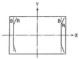
도 4는 크로스 미스컨버전스를 설명하기 위한 개략적 도면이고, 도 5는 R/B라인의 수직 미스컨버전스를 설명하기 위한 개략적 도면이다.FIG. 4 is a schematic diagram for explaining cross misconvergence, and FIG. 5 is a schematic diagram for explaining vertical misconvergence of an R / B line.
그러나, 종래의 기술에는 스크린상의 래스터의 상단부 및 하단부에서 발생된 편향 뒤틀림을 활용하기 위하여 자기장 분포가 조정되어질 경우, 도 4에 나타난바와 같이 조정된 자기장에서 크로스 미스컨버전스가 발생되기 쉽다는 문제점이 있다.However, in the related art, when the magnetic field distribution is adjusted to take advantage of the deflection distortion generated at the upper and lower ends of the raster on the screen, there is a problem that cross misconvergence is likely to occur in the adjusted magnetic field as shown in FIG. 4. .
상술한 크로스 미스컨버전스와 편향 뒤틀림을 모두 최소화하기 위하여, 종래의 기술에는 포화가능한 리액터 또는 정류기 회로를 사용하는 방법이 있다. 그러나, 이러한 방법은 장치의 크기 및 조립 경비의 증가뿐만 아니라 전자소자의 수를 증가시킨다.In order to minimize both the cross misconvergence and deflection distortion described above, there is a method in the prior art using a saturable reactor or rectifier circuit. However, this method increases the number of electronic devices as well as increasing the size and assembly cost of the device.
이와 반면에, 편향 뒤틀림이후에 발생하는 크로스 컨버전스를 보정하기 위하여 도 4에 보여준 방법이 활용되어져 왔기 때문에, 저렴한 경비등으로 원통형 수직 자기장의 조정방법이 있으며, X축에 근접한 영역에서 원통형 수직 자기장의 세기를 강화시키는 방법과 X축으로부터 떨어진 영역에서 원통형 수직 자기장의 세기를 약화시킬 수 있는 방법이 있다.On the other hand, since the method shown in Fig. 4 has been used to correct the cross convergence occurring after the deflection distortion, there is a method of adjusting the cylindrical vertical magnetic field at low cost, and the cylindrical vertical magnetic field in the region close to the X axis. There are methods to enhance the strength and to weaken the strength of the cylindrical vertical magnetic field in the region away from the X axis.
그러나, 본 방법에 있어서는, 도 5에 도시된 바와 같이, 실선으로 도시된 전자빔(R)과 점선으로 도시된 전자빔(B)이 스크린의 4개의 코너에서 서로 만나지 못함으로 인하여, 전자빔(R)이 전자빔(B)으로부터 오른쪽으로 떨어진 코너에서 R/B라인이 수직 미스컨버전스되는 새로운 문제점이 발생된다. 그 이유는 수직 방향에서의 편향 자기장 세기가 원통형 수직편향 자기장의 세기가 축(X)으로부터 떨어진 영역에서 보다 약해지기 때문에, 스크린의 4개의 코너에서 수평 방향에서의 편향 자기장의 세기보다 비교적 약해지게 되기 때문이다.However, in the present method, as shown in Fig. 5, since the electron beam R shown by the solid line and the electron beam B shown by the dotted line do not meet each other at four corners of the screen, the electron beam R is closed. A new problem arises in that the R / B lines are vertically misconverged at the corners away from the electron beam B to the right. The reason is that the deflection magnetic field strength in the vertical direction becomes weaker than the strength of the deflection magnetic field in the horizontal direction at four corners of the screen, because the strength of the cylindrical vertical deflection magnetic field is weaker in the area away from the axis X. Because.
따라서, 편향 뒤틀림과 크로스 미스컨버전스를 감소시키기 위한 새로운 설계가 제공되어야 한다.Therefore, a new design must be provided to reduce deflection distortion and cross misconvergence.
상기의 새로운 설계는 셀프 컨버전스형의 편향요크를 이용한 최근의 높은 정밀도 디스플레이 시스템의 성취와는 차이가 난다. 따라서, 새로운 개선이 요구된다.The new design differs from the achievement of recent high precision display systems using self-converged deflection yokes. Therefore, new improvements are required.
본 발명과 관련된 종래 기술에 의한 명세서를 이하에 기술한다.The specification by the prior art related to this invention is described below.
(1) 일본 실용 신안 공개공보 제 63-4053/1988 호.(1) Japanese Utility Model Publication No. 63-4053 / 1988.
종래 기술에 의한 수평편향 코일은 복수의 분할권선이 아니고 전방 마우스로 부터 후방 마우스까지 연장된 단일의 분할권선을 갖는다. 한편, 본 발명에 따른 수평편향 코일은, 본 발명에 따른 실시예에 기술된 바와 같이, 전방 및 후방 마우스 중 하나에 근접한 하나 이상의 제 1분할권선부와 2개의 주코일부의 각각의 후방 중간에 있는 제 2분할권선부를 갖는다.The horizontal deflection coil according to the prior art does not have a plurality of split windings but has a single split winding extending from the front mouse to the rear mouse. On the other hand, the horizontal deflection coil according to the present invention, as described in the embodiment according to the present invention, is located in the middle of the rear of each of the one or more first division windings and the two main coil portions proximate to one of the front and rear mice. It has a 2nd winding part.
따라서, 종래 기술에서는, 수평 편향요크의 조정된 자기장 분포 영역은, 그것이 전방측, 중간측 및, 후방측에서 동일한 권선수를 갖기 때문에, 본 발명의 그것과 비교하면 보다 좁게 된다.Thus, in the prior art, the adjusted magnetic field distribution region of the horizontal deflection yoke is narrower compared with that of the present invention because it has the same number of turns on the front side, the middle side, and the rear side.
(2) 일본 실용 신안 공개공보 제 2-64146/1990 호와 일본 특허 공보 제 7-105206/1995 호.(2) Japanese Utility Model Publication No. 2-64146 / 1990 and Japanese Patent Publication No. 7-105206 / 1995.
상기 명세서에 의한 종래 기술에서는, 본 발명의 제 2분할권선부에 대응되는 부분에 있어서, 창으로부터 떨어져 있는 코일부는 창을 향해 반대 방향으로 굴곡된다. 이것은 수평편향 코일의 다른 컨버전스 특성에 나쁜 영향을 미치게 된다.In the prior art according to the above specification, in a portion corresponding to the second divided winding portion of the present invention, the coil portion away from the window is bent in the opposite direction toward the window. This adversely affects other convergence characteristics of the horizontal deflection coil.
그런데, 본 발명에서는, 창에 근접한 코일부는 오직 창을 향해 굴곡된다. 이것은 굴곡부의 방향이 상기의 2가지 종래 기술과는 반대 방향이 된다. 따라서, R/B 라인의 수직 미스컨버전스와 크로스 미스컨버전스는 다른 컨버전스 특성들에 영향을 주지 않고도 효과적으로 제거될 수 있다.By the way, in the present invention, the coil part close to the window is bent toward the window only. This is the direction of the bend in the opposite direction to the above two prior arts. Thus, vertical misconvergence and cross misconvergence of the R / B line can be effectively eliminated without affecting other convergence characteristics.
따라서, 본 발명의 일반적인 목적은 상술한 결점들을 제거시키는 셀프 컨버전스 편향요크를 제공하는데 있다.Accordingly, it is a general object of the present invention to provide a self-convergence deflection yoke which eliminates the above mentioned drawbacks.
본 발명의 다른 목적은 장치의 크기와 제작 단가를 높이지 않고도, 편향 뒤틀림과 크로스 미스컨버전스를 감소시킬수 있는 셀프 컨버전스 편향요크를 제공하는데 있다.Another object of the present invention is to provide a self-convergence deflection yoke that can reduce deflection distortion and cross misconvergence without increasing the size and manufacturing cost of the device.
본 발명의 다른 목적은 전자빔을 방사시키기 위해 전자총을 갖는 컬러 CRT의 전자빔을 편향시키기 위해 셀프 컨버전스 시스템의 편향요크를 제공하는데 있으며, 상기 편향요크는 각각 중심부에서 창에 의해 분할되는 2개의 주코일부를 갖는 안장형태의 수평편향 코일 한쌍과, 한쌍의 안장형태의 수직편향 코일과, 편향요크의 전방 단부에서 전방 마우스를 형성하는 전방 림과, 편향요크의 후방 단부에서 후방마우스를 형성하는 후방 림과, 전방 및 후방 림들중 하나에 근접하는 하나 이상의 제 1분할권선부를 포함하며, 종래 기술에서 개선시킨 상기 편향요크의 장점은 제 2 분할권선부가 각각의 2개의 주코일부의 후방 중간에 있는 2개의 주코일부에서 제공되며, 제 2분할권선부가 창 근방에 위치된 제 1코일부안에서 분할되고, 제 2코일부는 각 주코일부에 형성된 소개구에 의해서 창으로부터 멀어지게 되고, 그리고, 제 1코일부는 창을 향해 굴곡되는 굴곡부를 갖는 것이다.Another object of the present invention is to provide a deflection yoke of a self-convergence system for deflecting an electron beam of a color CRT having an electron gun to emit an electron beam, wherein the deflection yoke comprises two main coil portions each divided by a window at a central portion thereof. A pair of saddle-shaped horizontal deflection coils, a pair of saddle-shaped vertical deflection coils, a front rim forming a front mouse at the front end of the deflection yoke, a rear rim forming a rear mouse at the rear end of the deflection yoke, An advantage of the deflection yoke, which is improved in the prior art, includes one or more first split windings proximate one of the front and rear rims, wherein the two split coils are in the middle of the rear half of each of the two main coils. And a second split winding portion is divided in a first coil portion located near the window, and a second coil portion is provided in each main coil portion. The introduction coil is formed to move away from the window, and the first coil portion has a bent portion that is bent toward the window.
본 발명의 또다른 특정 목적은 전자빔을 방사시키기 위해 전자총을 갖는 컬러 CRT의 전자빔을 편향시키기 위해 셀프 컨버전스 시스템의 편향요크를 제공하는데 있으며, 상기 편향요크는 그 각각이 중심부에서 창에 의해 분할되는 2개의 주코일부를 갖는 안장형태의 수평편향 코일 한쌍과, 한쌍의 안장형태의 수직편향 코일과, 편향요크의 전방 단부에서 전방 마우스를 형성하는 전방 림과, 편향요크의 후방 단부에서 후방 마우스를 형성하는 후방 림과 전방 림에 근접하게 제공된 제 1분할권선부 및, 후방 림에 근접하게 제공된 제 2분할권선부를 포함하며, 종래기술에서 개선시킨 상기 편향요크의 장점은 제 3분할권선부가 각각의 2개의 주코일부의후방 중간에 있는 2개의 주코일부에서 제공되며, 제 3분할권선부가 창에 근접하게 위치된 제 1코일부안으로 분리되고, 제 2코일부는 각 주코일부에 형성된 소개구에 의해서 창으로부터 떨어져 있고, 그리고, 제 1코일부는 창을 향해 굴곡되는 굴곡부를 갖는 것이다.Another particular object of the present invention is to provide a deflection yoke of a self-convergence system for deflecting an electron beam of a color CRT with an electron gun to emit an electron beam, the deflection yoke being two each divided by a window at the center. A pair of saddle-shaped horizontal deflection coils having two main coil portions, a pair of saddle-shaped vertical deflection coils, a front rim forming a front mouse at the front end of the deflection yoke, and a rear mouse at the rear end of the deflection yoke. Advantages of the deflection yoke improved in the prior art include a first split winding provided in close proximity to the rear rim and the front rim, and a second split winding provided in close proximity to the rear rim. It is provided from two main coil parts in the middle of the rear of the main coil part, and the third split winding part is located in the first coil part located close to the window. The second coil portion is separated from the window by an introduction port formed in each main coil portion, and the first coil portion has a curved portion that is bent toward the window.
본 발명의 다른 목적 및 추가적인 형태들은 이하 후술되는 기술내용에 의해 더욱 명확해질 것이다.Other objects and further aspects of the present invention will become more apparent from the following description.
도 1(A)는 셀프 컨버전스 편향요크의 수평편향 코일에 의해 형성된 핀쿠션 수평편향 자기장이 화살표로 표시되고, 전자빔들이 참조부호 B,G,R로 지시된, 세로방향(Z축)을 따라 취한, 종래 기술의 편향요크및 칼라 CRT의 주요 부분의 수직 단면도.1 (A) shows the pincushion horizontal deflection magnetic field formed by the horizontal deflection coil of the self-convergence deflection yoke, indicated by an arrow, and the electron beams are taken along the longitudinal direction (Z axis), indicated by the references B, G, R, Vertical cross-sectional view of the main portion of prior art deflection yoke and collar CRT.
도 1(B)는 셀프 컨버전스 편향요크의 원통형 수직편향 코일에 의해 형성된 핀쿠션 수직편향 자기장이 화살표로 표시되고, 전자빔들이 참조부호 C,G,R로 지시된, 세로 방향(Z축)을 따라 취한, 종래 기술의 편향요크 및 칼라 CRT의 주요 부분의 수직 단면도.FIG. 1 (B) shows the pincushion vertical deflection magnetic field formed by the cylindrical vertical deflection coil of the self-convergence deflection yoke, indicated by the arrow, and the electron beams taken along the longitudinal direction (Z axis), indicated by reference C, G, and R. FIG. Vertical cross-sectional view of the main part of the deflection yoke and collar CRT of the prior art.
도 2는 종래 기술의 한 쌍의 수평편향 코일중 하나가 도시된 Y축방향으로부터 본 ,수평편향 코일의 평면도.2 is a plan view of a horizontal deflection coil, seen from the Y-axis direction, in which one of a pair of prior art horizontal deflection coils is shown;
도 3은 종래기술에 따른 Z축방향에서 본 수평편향 코일의 정면도.Figure 3 is a front view of the horizontal deflection coil seen in the Z-axis direction according to the prior art.
도 4는 크로스 미스컨버전스를 설명하기 위한 개략적 도면.4 is a schematic diagram for explaining cross misconvergence.
도 5는 종래의 R/B 라인의 수직 미스컨버전스를 설명하기 위한 개략적 도면.5 is a schematic diagram for explaining a vertical misconvergence of a conventional R / B line.
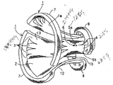
도 6은 본 발명에 따른 한 쌍의 섀들형 수평편향 코일중 하나를 도시한 사시도.Figure 6 is a perspective view of one of a pair of shaded horizontal deflection coils in accordance with the present invention.
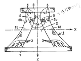
도 7은 Y축 방향에서 한 쌍의 섀들형 수평편향 코일중 하나를 도시한 평면도.FIG. 7 is a plan view showing one of a pair of shader-type horizontal deflection coils in the Y-axis direction. FIG.
도 8은 Z축 방향에서 본, 도 7에 도시한 수평편향 코일의 정면도.FIG. 8 is a front view of the horizontal deflection coil shown in FIG. 7 seen in the Z-axis direction. FIG.
도 9(A)와 도 9(B)는 본 발명에 따른 스크린상의 R/B 라인의 수직 미스컨버전스가 얼마나 보정되는가를 설명하는 개략도.9 (A) and 9 (B) are schematic diagrams illustrating how vertical misconvergence of an R / B line on a screen according to the present invention is corrected.
※ 도면의 주요부분에 대한 부호의 설명 ※※ Explanation of code about main part of drawing ※
1 : 수평편향 코일 2 : 창1: horizontal deflection coil 2: window
3 : 제 1분할권선부 4 : 제 2분할권선부3: first division winding unit 4: second division winding unit
5 : 제 3분할권선부 6 : 소개구5: third division winding division 6: introduction section
5a : 제 1코일부 5b : 제 2코일부5a:
12,13 : 주코일부12,13: main coil part
도 6은 본 발명에 따른 한 쌍의 섀들형 수평편향 코일중 하나를 도시한 사시도이고;FIG. 6 is a perspective view of one of a pair of shaded horizontal deflection coils in accordance with the present invention; FIG.
도 7은 Y축 방향에서 한 쌍의 섀들형 수평편향 코일중 하나를 도시한 평면도이며;7 is a plan view showing one of a pair of shaded horizontal deflection coils in the Y-axis direction;
도 8은 Z축 방향에서 본, 도 7에 도시한 수평편향 코일의 정면도이다.FIG. 8 is a front view of the horizontal deflection coil shown in FIG. 7 seen in the Z-axis direction. FIG.
도 6 내지 도 8을 참조하여 본 발명의 셀프 컨버전스의 편향요크의 실시예에 대한 설명이 주어진다.A description is given of embodiments of the self-convergence deflection yoke of the present invention with reference to FIGS.
본 발명의 편향요크는 일반적으로, 도 6에 도시한 한 쌍의 섀들형 수평편향 코일(1)과 도시안된 세퍼레이터가 칼러 CRT의 외부면상에 장착된 한 쌍의 섀들형 수직편향 코일(도시안함)을 포함한다.The deflection yoke of the present invention generally includes a pair of shader-type horizontal deflection coils 1 shown in FIG. 6 and a pair of shader-type vertical deflection coils (not shown) in which an unillustrated separator is mounted on the outer surface of the color CRT. It includes.
한 쌍의 섀들형 수평편향 코일(수평편향 코일로 지시;1)은 각각 일반적으로 섀들형이며 와이어가 제공되지 않은 창(2)을 형성하도록 권선된다. 수평편향 코일(1)은 주권선부(12, 13)사이에 배치된 창(2)의 양 측부에 형성된 한 쌍의 주권선부(12,13)를포함하여 한 쌍의 주권선부(12,13)가 Z축에 대해 대칭되게 하고, 머리부가 절단된 콘형을 이루도록 Z축을 따라 연장된다. 수평편향 코일(1)은 각각 편향요크의 전방단부에 큰 반원을 가지는 수평 전방 마우스(1a)을 큰 반원 림(7)에의해서, 편향요크의 후방단부에 큰 반원를 가지는 수평 후방 마우스(1b)를 작은 반원림(8)에 의해서 수평편향 코일(1)이 콘형을 갖는 칼러 CRT(도시안함)의 목부에 장착되게 한정된다.A pair of saddle-shaped horizontal deflection coils (indicated by horizontal deflection coils; 1) are each wound to form a
큰 반원 림(7)과 작은 반원 림(8)은 그것의 단부에서 한 쌍의 주권선부(12,13)와 연결하는 기능을 가진다.The large
주권선부(12,13)는 각각 큰 반원 림(7)근방에 제 1분할권선부(3)를 가지고 작은 반원 림(8)근방에 제 2분할권선부(4)를 가진다.The
또한,주권선부(12,13)는 각각 본 발명의 주요 특징인 제 3분할권선부(5)를 주권선부(12,13)의 후방 중심부에 구비한다.In addition, the winding portion (12, 13) is provided with a third divided winding
제 3분할권선부(5)는 삼각형을 가지는 소개구(6)에 의해 제 1코일부(5a)와 제 2 코일부(5b)로 분할된다. 굴곡부(5a1)는 제 1 및 제 2코일부(5a,5b)사이에 소개구(6)를 한정하는 창(2)를 향하는 방향으로 단지 한 쌍의 제 1코일부(5a)가 굴곡되게 형성시킨다.The third
상기 실시예의 셀프 컨버전스 편향요크는 앞서 언급한 것처럼 한 쌍의 수직편향 코일(도시안함)을 부가로 구비한다. 그러나, 기초 구조와 그 작용은 도 1(B)를 참조하여 설명한다. 그러므로, 여기에서 그 상세한 설명은 생략한다.The self-convergence deflection yoke of the above embodiment additionally includes a pair of vertical deflection coils (not shown). However, the basic structure and its operation will be described with reference to Fig. 1B. Therefore, detailed description thereof is omitted here.
다음으로, 상술한 구조의 편향 코일의 작용에 대해 설명한다.Next, the operation of the deflection coil of the above-described structure will be described.
본 발명의 수평편향 코일(1,1)에는, 주권선부(12,13)의 전방 및 후방 림(7,8)에 근접하게 제 1 및 제 2분할권선부(3,4)들이 설치된다. 따라서, 수평편향 코일(1)에 의해 발생하는 핀쿠션 수평 자기장의 세기를 부분적으로 용이하게 조정할수 있다. 이로 인해, 화면상의 상,하변의 편향 뒤틀림 또는 수평 코마 오차를 최소화할 수 있고, 따라서, 편향요크의 설계 및 제조에 있어서 수평편향 코일(1)을 최적으로 조정할 수 있다.In the horizontal deflection coils 1 and 1 of the present invention, first and second
또한, 전술했듯이, 각각의 주권선부(12,13)에는 제 1코일부(5a)에 굴곡부(5a1)을 갖는 제 3분할권선부(5)을 구비하며, 칼라 CRT의 세로 방향 (z축)으로 보아서 후방 단부에서 중간부와 제 2분할권선부(4)사이에는 창(2)쪽으로 돌출하는 삼각형상의 소개구(6)가 형성된다.In addition, as described above, each main winding
전술한 바와 같이, 제 3분할권선부(5)가 배치되므로, 핀쿠션 수평 자기장은, 세로 방향(z축 방향)으로 보아서 중간부와 후방 림(8) 사이의 지점에 형성되는 삼각형상의 소개구(6)에 대응되는 영역에서는 약해진다.As described above, since the third
도 9(A)와 도 9(B)는 본 발명에서 화면상의 수직 미스컨버전스 R/B 라인을 어떻게 보정하는지를 설명하는 개략도이다.9 (A) and 9 (B) are schematic diagrams illustrating how to correct a vertical misconvergence R / B line on a screen in the present invention.
상기 핀쿠션 수평 자기장는 전체 수직 R라인이 수직 B라인으로부터 왼쪽으로 상대적으로 편향되도록 수평 방향(x축 방향)으로 수직 R/B 라인의 컨버전스 효과를 낸다. 상기 R/B 라인의 컨버젼스를 보정하기 위해서, 상기 제 1분할권선부(3)는 공지된 방법으로 재설계된다. 그 결과, 도 9(A)에 도시되어 있듯이, 수직 R라인은 화면의 4개의 코너에서 수직 B 라인으로부터 왼쪽으로 상대적으로 편향된다.The pincushion horizontal magnetic field produces a convergence effect of the vertical R / B line in the horizontal direction (x-axis direction) such that the entire vertical R line is relatively biased from the vertical B line to the left. In order to correct the convergence of the R / B lines, the first
4개의 코너에서의 수직 R 라인의 편향량은 제 1코일부분(5a)의 권선수와, 굴곡부(5a1)의 각도 및, 소개구(6)의 치수와 형상에 의해 제어된다.The amount of deflection of the vertical R lines at four corners is controlled by the number of turns of the
또한, 굴곡부(5a1)가 소개구(6)를 형성하도록 창(2)쪽으로만 바이어스될수록, 굴곡부가 없는 제 2코일부(5b)는 굴곡부(5a1)를 제공하는 것에 의해 전혀 영향을 받지 않으며, 그 결과 제 2코일부(5b)에 의한 자기장 분포의 변화는 전혀 없다.Further, as the bent portion 5a1 is biased only toward the
따라서, 본 발명에서는, 도 9(A)에 도시되어 있듯이, 수직 R 라인이, 도 4에 도시된 크로스 미스컨버전스의 보정에 의해 야기되는, 도 5에 도시된 오른쪽 방향으로의 4개의 코너에서의 수직 R 라인의 편향량에 상응되는 양만큼, 4개의 코너에서 왼쪽 방향으로 미리 편향된다. 수직 R 라인의 예비 편향량은 전술했듯이, 제 1 코일부(5a)의 조건을 조절하므로써 조정될수 있다.Therefore, in the present invention, as shown in Fig. 9A, the vertical R lines are drawn at four corners in the right direction shown in Fig. 5 caused by the correction of the cross misconvergence shown in Fig. 4. By the amount corresponding to the amount of deflection of the vertical R line, it is previously deflected in the left direction at four corners. The preliminary deflection amount of the vertical R line can be adjusted by adjusting the conditions of the
이후, 화면의 래스터의 상,하부에서 발전된 편향 뒤트림을 최적화하므로써, 크로스 미스컨버전스가 전술한 방법, 즉 X축 근접의 영역에서는 원통형 수직 자기장의 세기를 강화시키고 X축으로부터 떨어진 영역에서는 그 세기를 약화시키는 방법에 의해 수정된다.Then, by optimizing the deflection distortion developed in the upper and lower parts of the raster of the screen, cross misconvergence enhances the strength of the cylindrical vertical magnetic field in the above-described method, that is, in the region near the X axis and in the region away from the X axis. Corrected by a weakening method.
따라서, 크로스 미스컨버전스의 수정에 의해 발생한 오른쪽 방향으로의 4개의 코너에서의 수직 R 라인의 편향량은, 4개의 코너에서의 수직 R 라인의 왼쪽 방향 예비 편향량에 의해 오프셋된다. 따라서, 크로스 미스컨버전스를 수정하므로써 발생되는 R/B 라인의 수직 미스컨버전스가 효과적으로 제거될 수 있다.Therefore, the deflection amount of the vertical R line at the four corners in the right direction caused by the correction of the cross misconvergence is offset by the leftward deflection amount of the vertical R line at the four corners. Therefore, the vertical misconvergence of the R / B line generated by correcting cross misconvergence can be effectively eliminated.
전술했듯이, 본 발명의 셀프 컨버전스형 편향요크 실시예에 따르면, 다른 컨버전스 특성에 영향을 주지 않고, R/B 라인의 크로스 미스컨버전스 및 수직 미스컨버전스가 효과적으로 제거될 수 있다.As described above, according to the self-converged deflection yoke embodiment of the present invention, cross misconvergence and vertical misconvergence of the R / B line can be effectively removed without affecting other convergence characteristics.
또한, 본 실시예에 따르면, 셀프 컨버전스형 편향요크의 크기 및 제조단가를 증가시키지 않고서도, 포화가능한 리액터 또는 정류기 회로를 사용하지 않고, 수평편향 코일의 형상을 약간 변화시키므로써 셀프 컨버전스형 편향요크를 실현시킬 수 있다.Further, according to this embodiment, the self-converging deflection yoke is made by slightly changing the shape of the horizontal deflection coil without using a saturable reactor or rectifier circuit without increasing the size and manufacturing cost of the self-converging deflection yoke. Can be realized.
또한, 본 실시예에 따르면, 제 1, 제 2, 제 3분할권선부(3,4,5)들사이의 권선수가 상호 완전히 독립적이어서 개별적으로 제어될 수 있으므로, 이들 권선수사이의 권선수비를 결정하므로써 자기장의 분포를 정확히 조정할 수 있다.Further, according to the present embodiment, since the number of turns between the first, second, and
본 실시예에서는, 제 1 및 제 2분할권선부(3,4)에 관한 한, 이들이 주코일부(12,13)의 후방 및 전방 단부에 제공되지만, 그 전방 또는 후방 단부에 단지 하나의 분할권선부를 제공할 수 있다.In this embodiment, as far as the first and
또한, 제 1 및 제 2코일부(5a,5b)사이에 개재되는 소개구(6)의 형상은 삼각형상으로만 제한되지 않는다. 수직 R 라인의 편향량을 고려하여 예를 들어, 사다리꼴 또는 반원형등이 사용될 수 있다.In addition, the shape of the
Claims (8)
Applications Claiming Priority (2)
| Application Number | Priority Date | Filing Date | Title |
|---|---|---|---|
| JP6538496 | 1996-02-26 | ||
| JP96-65384 | 1996-02-26 |
Publications (2)
| Publication Number | Publication Date |
|---|---|
| KR970063371A KR970063371A (en) | 1997-09-12 |
| KR100335025B1 true KR100335025B1 (en) | 2002-12-02 |
Family
ID=13285445
Family Applications (1)
| Application Number | Title | Priority Date | Filing Date |
|---|---|---|---|
| KR1019970005952A KR100335025B1 (en) | 1996-02-26 | 1997-02-26 | Deflection Yoke |
Country Status (4)
| Country | Link |
|---|---|
| US (1) | US5838099A (en) |
| KR (1) | KR100335025B1 (en) |
| CN (1) | CN1123045C (en) |
| TW (1) | TW320731B (en) |
Cited By (1)
| Publication number | Priority date | Publication date | Assignee | Title |
|---|---|---|---|---|
| KR20030049155A (en) * | 2001-12-14 | 2003-06-25 | 삼성전기주식회사 | Deflection coil for deflection yoke |
Families Citing this family (11)
| Publication number | Priority date | Publication date | Assignee | Title |
|---|---|---|---|---|
| FR2757680B1 (en) * | 1996-12-20 | 1999-01-29 | Thomson Tubes & Displays | COLOR CATHODE RAY TUBE BYPASS UNIT WITH SADDLE DIVERTER |
| FR2757678B1 (en) * | 1996-12-20 | 1999-01-29 | Thomson Tubes & Displays | DEVIATION UNIT FOR AUTOCONVERGENT CATHODIC RAY TUBE WITH SADDLE-SHAPED DEVIATION COILS |
| US6326742B1 (en) * | 1998-10-28 | 2001-12-04 | Matsushita Electric Industrial Co., Ltd. | Color CRT with cross-misconvergence correction device |
| WO2000044028A2 (en) * | 1999-01-22 | 2000-07-27 | Koninklijke Philips Electronics N.V. | Deflection unit for a cathode ray tube |
| US6573648B1 (en) | 1999-11-19 | 2003-06-03 | Sony Corporation | Deflection yoke with openings in neck bend section |
| US6278348B1 (en) | 1999-11-19 | 2001-08-21 | Sony Corporation | Deflection yoke |
| JP3410441B2 (en) * | 2000-03-06 | 2003-05-26 | 日本ビクター株式会社 | Deflection yoke |
| US6624560B2 (en) | 2001-05-22 | 2003-09-23 | Sony Corporation | Deflection yoke |
| US6586893B2 (en) * | 2001-09-12 | 2003-07-01 | Song O Shik | Convergence correction device for electron beams in color picture tube and process of using |
| US6636006B2 (en) | 2001-12-06 | 2003-10-21 | Sony Corporation | Deflection yoke with multiple pairs of vertical coils and switched deflection current |
| US6924590B2 (en) * | 2002-02-21 | 2005-08-02 | Matsushita Electric Industrial Co., Ltd. | Color picture tube device with distortion correction coils |
Citations (1)
| Publication number | Priority date | Publication date | Assignee | Title |
|---|---|---|---|---|
| JPS5514285A (en) * | 1978-07-18 | 1980-01-31 | Sumitomo Electric Ind Ltd | Flexible film repairing method |
Family Cites Families (9)
| Publication number | Priority date | Publication date | Assignee | Title |
|---|---|---|---|---|
| US4039988A (en) * | 1973-07-23 | 1977-08-02 | U.S. Philips Corporation | Deflection coil having sections with minimum winding density portions and spaces |
| NL8004114A (en) * | 1980-07-17 | 1982-02-16 | Philips Nv | COLOR IMAGE TUBE WITH DEFLECTION YEAR AND DEFLECTION Yoke FOR COLOR IMAGE TUBE. |
| JPS634053A (en) * | 1986-06-24 | 1988-01-09 | Susumu Ishikawa | Method for forming patina film on surface of copper product or the like |
| JPS634053U (en) * | 1986-06-27 | 1988-01-12 | ||
| JPH0264146A (en) * | 1988-08-30 | 1990-03-05 | Idemitsu Petrochem Co Ltd | Copolyester resin composition |
| SG93772A1 (en) * | 1989-10-31 | 2003-01-21 | Thomson Tubes & Displays | Color picture tube display device |
| JPH0264146U (en) * | 1988-11-04 | 1990-05-14 | ||
| JPH02216738A (en) * | 1989-02-16 | 1990-08-29 | Matsushita Electric Ind Co Ltd | Deflection yoke |
| KR100260802B1 (en) * | 1991-11-01 | 2000-07-01 | 요트.게.아. 롤페즈 | Display tube with deflection unit comprising field deflection coil of the semi-saddle type |
-
1997
- 1997-02-20 TW TW086102034A patent/TW320731B/zh active
- 1997-02-25 US US08/805,431 patent/US5838099A/en not_active Expired - Fee Related
- 1997-02-26 CN CN97110066A patent/CN1123045C/en not_active Expired - Fee Related
- 1997-02-26 KR KR1019970005952A patent/KR100335025B1/en not_active IP Right Cessation
Patent Citations (1)
| Publication number | Priority date | Publication date | Assignee | Title |
|---|---|---|---|---|
| JPS5514285A (en) * | 1978-07-18 | 1980-01-31 | Sumitomo Electric Ind Ltd | Flexible film repairing method |
Cited By (1)
| Publication number | Priority date | Publication date | Assignee | Title |
|---|---|---|---|---|
| KR20030049155A (en) * | 2001-12-14 | 2003-06-25 | 삼성전기주식회사 | Deflection coil for deflection yoke |
Also Published As
| Publication number | Publication date |
|---|---|
| KR970063371A (en) | 1997-09-12 |
| US5838099A (en) | 1998-11-17 |
| TW320731B (en) | 1997-11-21 |
| CN1123045C (en) | 2003-10-01 |
| CN1166692A (en) | 1997-12-03 |
Similar Documents
| Publication | Publication Date | Title |
|---|---|---|
| KR100335025B1 (en) | Deflection Yoke | |
| US5408163A (en) | Self converging wide screen color picture tube system | |
| US4041428A (en) | Deflection yoke for use with in-line cathode ray tubes | |
| KR100432059B1 (en) | Color cathode-ray tube device | |
| JP4240541B2 (en) | Deflection yoke and geometric distortion correction | |
| US5461278A (en) | Electron gun and cathode-ray tube comprising the same | |
| CA1126320A (en) | Self-converging deflection units for colour display tubes of different screen formats | |
| EP0311806B1 (en) | Deflection unit for a colour cathode ray apparatus | |
| US4933596A (en) | Deflection yoke with compensation for misconvergence by the horizontal center raster | |
| US4305055A (en) | Television display system incorporating a coma corrected deflection yoke | |
| KR100468135B1 (en) | Deflection yoke and cathode ray tube apparatus having the same | |
| US4754189A (en) | Color television display tube with coma correction | |
| KR100463718B1 (en) | Color cathode ray tube apparatus | |
| CN100474493C (en) | Deflection device comprising saddle-shape vertical deflection coil for cathode-ray tube | |
| US6756726B2 (en) | Deflection yoke and cathode-ray tube apparatus with the same | |
| KR100739592B1 (en) | Deflection apparatus for cathode ray tube | |
| KR100467845B1 (en) | Coil for Deflection Yoke | |
| KR100814873B1 (en) | Deflection apparatus for cathode ray tube | |
| US6072379A (en) | Saddle shaped deflection winding having winding spaces in the rear | |
| KR100731625B1 (en) | Separater of deflection yoke | |
| JP3215132B2 (en) | In-line color picture tube device | |
| KR0177118B1 (en) | Deflection yoke of color cathode ray tube | |
| KR100459994B1 (en) | Deflection yoke | |
| JPS5925080Y2 (en) | Semi-toroidal electromagnetic deflection yoke | |
| JP2000353479A (en) | Deflection yoke and cathode-ray tube receiver using it |
Legal Events
| Date | Code | Title | Description |
|---|---|---|---|
| A201 | Request for examination | ||
| E902 | Notification of reason for refusal | ||
| E902 | Notification of reason for refusal | ||
| E701 | Decision to grant or registration of patent right | ||
| GRNT | Written decision to grant | ||
| FPAY | Annual fee payment |
Payment date: 20090320 Year of fee payment: 8 |
|
| LAPS | Lapse due to unpaid annual fee |