KR100318247B1 - Dual Event Valve Control System - Google Patents
Dual Event Valve Control System Download PDFInfo
- Publication number
- KR100318247B1 KR100318247B1 KR1019970034277A KR19970034277A KR100318247B1 KR 100318247 B1 KR100318247 B1 KR 100318247B1 KR 1019970034277 A KR1019970034277 A KR 1019970034277A KR 19970034277 A KR19970034277 A KR 19970034277A KR 100318247 B1 KR100318247 B1 KR 100318247B1
- Authority
- KR
- South Korea
- Prior art keywords
- rocker arm
- cam
- rocker
- control system
- rocker arms
- Prior art date
Links
Images


Classifications
-
- F—MECHANICAL ENGINEERING; LIGHTING; HEATING; WEAPONS; BLASTING
- F01—MACHINES OR ENGINES IN GENERAL; ENGINE PLANTS IN GENERAL; STEAM ENGINES
- F01L—CYCLICALLY OPERATING VALVES FOR MACHINES OR ENGINES
- F01L1/00—Valve-gear or valve arrangements, e.g. lift-valve gear
- F01L1/12—Transmitting gear between valve drive and valve
- F01L1/18—Rocking arms or levers
- F01L1/185—Overhead end-pivot rocking arms
-
- F—MECHANICAL ENGINEERING; LIGHTING; HEATING; WEAPONS; BLASTING
- F01—MACHINES OR ENGINES IN GENERAL; ENGINE PLANTS IN GENERAL; STEAM ENGINES
- F01L—CYCLICALLY OPERATING VALVES FOR MACHINES OR ENGINES
- F01L13/00—Modifications of valve-gear to facilitate reversing, braking, starting, changing compression ratio, or other specific operations
- F01L13/0015—Modifications of valve-gear to facilitate reversing, braking, starting, changing compression ratio, or other specific operations for optimising engine performances by modifying valve lift according to various working parameters, e.g. rotational speed, load, torque
- F01L13/0036—Modifications of valve-gear to facilitate reversing, braking, starting, changing compression ratio, or other specific operations for optimising engine performances by modifying valve lift according to various working parameters, e.g. rotational speed, load, torque the valves being driven by two or more cams with different shape, size or timing or a single cam profiled in axial and radial direction
-
- F—MECHANICAL ENGINEERING; LIGHTING; HEATING; WEAPONS; BLASTING
- F01—MACHINES OR ENGINES IN GENERAL; ENGINE PLANTS IN GENERAL; STEAM ENGINES
- F01L—CYCLICALLY OPERATING VALVES FOR MACHINES OR ENGINES
- F01L2820/00—Details on specific features characterising valve gear arrangements
- F01L2820/03—Auxiliary actuators
- F01L2820/031—Electromagnets
Abstract
내연기관용 이중 이벤트(event) 제어시스템(10), 상기 시스템은 밸브(12) 및 제1 캠(18)과 맞물리는 내부 로커암(22)과, 제2 캠(20)과 맞물리는 외부 로커암 (26)과, 로커암들간에 삽입할 수 있는 래치부재(68)를 포함하고, 로커암들이 래치부재(68)를 맞물리지 않을 때, 로커암들은 서로 독립적으로 퍼벗으로 선회하기에 자유롭고 밸브(12)는 제1 캠(18)의 리프트 프로파일에 따라 제1 로커암(22)에 의해 작동되고, 로커암들이 래치부재(68)에 의해 맞물려질 때, 로커암들은 일치해서 회전하고 밸브(12)는 제2 캠(20)의 리프트 프로파일에 따라 제2 로커암(26)에 의해 작동된다. 내부(22) 및 외부(26) 로커암간의 정지동작(86)은 로커암간의 상대적인 피벗 이동을 제한하고, 제2 캠(20)의 기초원과 외부 로커암(26)간의 틈새(C)를 구성하는 데 효과적이다.Dual event control system 10 for an internal combustion engine, the system having an internal rocker arm 22 that engages the valve 12 and the first cam 18, and an external rocker arm that engages the second cam 20. 26 and a latch member 68 that can be inserted between the rocker arms, and when the rocker arms do not engage the latch member 68, the rocker arms are free to pivot independently of each other and the valve ( 12 is actuated by the first rocker arm 22 according to the lift profile of the first cam 18 and when the rocker arms are engaged by the latch member 68, the rocker arms rotate in unison and the valve 12 ) Is actuated by the second rocker arm 26 according to the lift profile of the second cam 20. The stop motion 86 between the inner 22 and outer 26 rocker arms limits the relative pivotal movement between the rocker arms and closes the clearance C between the base circle of the second cam 20 and the outer rocker arm 26. It is effective to construct.
Description
본 발명은 내연기관용 밸브동작장치, 더욱 상세하게는 엔진의 각종 운전모드 동안에 그 엔진에서 흡기 또는 배기밸브의 동작 특성을 변화시키는 장치에 관한 것이다.The present invention relates to a valve operating device for an internal combustion engine, and more particularly to a device for changing the operating characteristics of an intake or exhaust valve in an engine during various modes of operation of the engine.
흡기 및/또는 배기밸브를 선택적으로 작동시킬수 있거나 선택된 리프트 프로파일(lift profile)에서 작동시킬 수 있는 다중밸브 엔진용 가변밸브 제어시스템이 상기 기술에서 공지되어 있다. 미합중국특허 제4,151,817호는 제1 캠 프로파일과 맞물려질 수 있는 제1 로커암 소자와, 제1 로커암 소자상에 피벗으로 실장되어 제2 캠 프로파일과 맞물려질 수 있는 제2 로커암 소자와, 제1 및 제2 로커암 소자를 상호 연결하거나 래치(latch)하는 수단을 포함하는 시스템을 개시한다.Variable valve control systems for multivalve engines are known in the art that can selectively operate intake and / or exhaust valves or operate at selected lift profiles. U.S. Patent No. 4,151,817 describes a first rocker arm element that can be engaged with a first cam profile, a second rocker arm element that can be pivotally mounted on the first rocker arm element and that can be engaged with a second cam profile; A system is disclosed that includes means for interconnecting or latching a first and a second rocker arm element.
1995년 3월 28일에 출원된 미합중국특허 출원 제412,474호는 고정 래시(lash)조절기의 출력부재상에서 피벗으로 실장된 내부 및 외부 로커암을 포함하는 시스템을 개시하고, 외부 로커암은 엔진밸브와 맞물려지고 내부 로커암은 캠과 맞물려지고, 래치부재는 내부 및 외부 로커암의 접촉표면간에 선택적으로 삽입되어 밸브 개방력을 캠으로부터 외부 로커암으로 보내기 위해 로커암들을 함께 효과적으로 래치한다. 로커암들이 래치안된 상태에 있을 때 외부 로커암은 내부 로커암에 대해 회전하기에 자유롭고 개방력이 외부 로커암에 보내지지 않는다.United States Patent Application No. 412,474, filed March 28, 1995, discloses a system comprising internal and external rocker arms pivotally mounted on an output member of a fixed lash regulator, the external rocker arm being coupled to an engine valve. The inner rocker arm is engaged with the cam, and the latch member is selectively inserted between the contact surfaces of the inner and outer rocker arms to effectively latch the rocker arms together to transfer the valve opening force from the cam to the outer rocker arm. When the rocker arms are in the unlatched state, the outer rocker arm is free to rotate relative to the inner rocker arm and no opening force is sent to the outer rocker arm.
본 발명의 목적은 이중 이벤트(event) 밸브제어시스템을 구성하는 것으로, 엔진밸브는 2개의 다른 캠 프로파일중 하나에 의해 선택적으로 작동되고 그것은 래치부재가 로커암들간에 삽입되었을 때 로커암을 제1 캠 프로파일에 따라 밸브를 작동시키기 위해 일치해서 이동시키고 또한 래치부재가 로커암들간에 삽입되지 않았을 때 로커암을 제2 캠 프로파일에 따라 밸브를 작동시키기 위해 서로에 대해 이동하도록 내부 및 외부 로커암상에 형성된 접촉 소자간에 선택적으로 삽입되는 래치부재에 의해 작동된다.It is an object of the present invention to construct a dual event valve control system wherein the engine valve is selectively actuated by one of two different cam profiles, which firstly locks the rocker arm when the latch member is inserted between the rocker arms. On the inner and outer rocker arms to coincidely move to actuate the valve according to the cam profile and to move the rocker arms relative to each other to actuate the valve according to the second cam profile when the latch member is not inserted between the rocker arms. It is operated by a latch member which is selectively inserted between the formed contact elements.
상기 목적에 부합하기 위해, 본 발명은 밸브에 맞물리고 내부 암(arm)을 둘러싸는 관계인 내부 로커암을 포함하고 제2 캠에 접촉하는 그 위에 형성된 표면을 갖는 로커암 어셈블리와, 내부 및 외부 로커암과 맞물리지 않는 제1 위치와 그 암들의 상대적인 회전을 방해하기 위해 내부 및 외부 암들의 접촉표면사이에 삽입되어서 암들을 함께 효과적으로 래치하는 제2 위치사이에서 이동 가능한 래치부재를구성한다. 제2 캠들이 제1 캠보다 더 높은 리프트 프로파일을 갖게 되도록 캠들을 구성한다. 래치부재가 제1 위치에 있을 때는 제2 캠의 힘은 내부 암에 전달되지 않고 내부 암상에 직접적으로 동작하는 저 리프트 캠만이 밸브를 효과적으로 개방시킨다. 래치부재의 제2 위치에서는 제2 캠의 힘이 외부 로커암으로부터 내부 로커암으로 보내져서 밸브로 보내지고, 저 리프트 캠 프로파일은 이러한 모드의 동작에서는 효율적이지 않다. 마모를 감소시키기 위해, 정지수단을 캠 또는 래시가 제2 캠 및 외부 로커 암의 캠 접촉표면간에 유지되도록 내부 및 외부 로커암간의 상대적인 분리 운동을 제한하기 위해 구성한다.To meet the above object, the present invention includes an inner rocker arm assembly having an inner rocker arm in a relationship to engage a valve and surrounding an inner arm and having a surface formed thereon in contact with the second cam, and an inner and outer rocker It constitutes a latch member that is movable between a first position that does not engage the arm and a second position that is inserted between the contact surfaces of the inner and outer arms to prevent relative rotation of the arms to effectively latch the arms together. Configure the cams such that the second cams have a higher lift profile than the first cam. When the latch member is in the first position, the force of the second cam is not transmitted to the inner arm and only the low lift cam that operates directly on the inner arm effectively opens the valve. In the second position of the latch member the force of the second cam is sent from the outer rocker arm to the inner rocker arm and sent to the valve, and the low lift cam profile is not efficient in this mode of operation. To reduce wear, stop means are configured to limit the relative separation movement between the inner and outer rocker arms such that the cam or lash is held between the cam contact surface of the second cam and the outer rocker arm.
본 발명의 다른 목적 및 장점은 첨부 도면을 연관지어 생각할 때 다음의 설명으로부터 명백해진다.Other objects and advantages of the present invention will become apparent from the following description when considered in conjunction with the accompanying drawings.
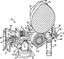
도 1은 본 발명의 투시도.1 is a perspective view of the present invention.
도 2는 본 발명의 평면도.2 is a plan view of the present invention.
도 3은 도 2의 선 3-3을 따라 취해진 단면도.3 is a cross-sectional view taken along line 3-3 of FIG.
도 4는 본 발명의 투시 단면도.4 is a perspective cross-sectional view of the present invention.
도면은 오버헤드 캠 형태의 내연기관(도시않됨)에서 사용하기 위해 특별히 채용된 밸브제어시스템(10)을 예시한다. 여기에서 나타낸 바와 같이 시스템(10)은 2개의 별개의 캠 프로파일중 하나에 응답해서 포핏(poppet)밸브(12)(도 4 참조)를 개방하는 동작이 가능하고, 로커암 어셈블리(14) 및 2개의 동작 모드간에 로커암 어셈블리를 시프트시키는 동작이 가능한 래치 어셈블리(16)를 포함한다. 여기에 나타낸 실시예에서 제1 캠(18)(도 3)은 제1 동작 모드를 형성하고, 하나 이상의 제2 캠(20)은 제2동작 모드를 형성한다.The figure illustrates a
로커암 어셈블리(14)는 캠축(24)상에 형성된 제1 캡(18) 및 밸브(12)(도 4)와 맞물릴 수 있는 내부 로커암(22)과, 제2 캠(20)과 맞물릴 수 있고 스프링쌍(28, 29)에 의해 로커암(26)을 바이어스하여 캠축(20)과 맞물리게 하는 외부 로커암(26)을 포함한다. 로커암 어셈블리는 엔진의 실린더 헤드(31)상에서 피벗으로 실장되고, 도 4에 도시된 바람직한 실시예에서, 그것은 유압 래시(lash)조절기(32)의 출력부재(30)상에 실장된다. 래시조절기의 구조 및 기능이 잘 공지되어 있으며 여기에서 상세하게 설명하지 않는다.The
특히 도 2 및 도 3에서, 내부 로커암(22)은 멀리 떨어진 측벽(34, 35)을 갖는 스탬프된 박스형 부재와, 밸브접촉소자(36)를 형성하기 위해 수렴하는 제1단부와, 스파인(spine)(38)형태의 제2 단부를 포함하며, 그것들의 기능을 다음에서 더 상세하게 설명한다. 스파인에 인접한 측벽(34, 35)의 단부는 스프링(28, 29)의 한 단부에 대해 정지부 역할을 하는 탭(tab)(40, 41)을 형성하기 위해 외부방향으로 구부려진다. 정렬된 보어(도시않됨)는 측벽에 형성되어 제1 캠(18)과 맞물릴 수 있는 제1 폴로워(follower)를 형성하는 롤러 어셈블리(44)의 액슬(42)을 수납한다.In particular in FIGS. 2 and 3, the
내부 암은, 하기에서 더 상세하게 설명되듯이, 내부 및 외부 로커암의 측벽에 형성된 개구를 통해 수납되는 바(46)에 의해 형성된 받침대위에 실장된다.The inner arm is mounted on a pedestal formed by a
외부 로커암(26)은, 도 2에 도시한 바와 같이, 내부 암(22)을 둘러싸는 관계로 수납되는 박스형 구조이다. 외부 암은 서로 간격을 둔 측벽(48, 49)과, 그 위에 형성된 제1 접촉표면(52)을 갖는 제1 단부벽(50)과, 그 위에 형성된 중앙 스파인(56)을 갖는 제2 단부벽(54)을 포함하며, 그것들의 기능은 하기에서 설명한다. 각각의 측벽(48, 49)은 그 위에 형성된 탭(58, 59, 60)을 가져서 그것에, 패드(62)가 브레이즈(braze)되거나 그렇지 않으면 부착되고, 패드(62)는 바람직한실시예에서 캠(18)을 걸치는 제2 캠(20)에 의해 맞물려질 수 있는 제2 폴로워를 형성한다.As shown in FIG. 2, the
도 4를 특히 참조하면, 외부 로커암은 출력부재상에서 형성된 볼(ball)단부와 맞물려질 수 있고 거기에 형성되어 중심에 위치한 소켓(47)을 보유하며 측벽(48, 49)에 형성된 개구를 통해 수납되는 바(46)로써, 래시조절기(32)의 출력부재(30)에 대해 피벗 운동하도록 실장된다. 외부 로커암의 벽(48, 49)에 형성된 개구는 바(46)에 대해 최소 틈새로 형성되어서 암 및 바사이의 상대적인 운동은 거의 없다. 그러나, 내부 암(22)에 형성된 개구는 바(46)보다 어느 정도 커서 내부 암이 바의 아치형 상부표면(64)에 대해 피벗 운동할 수 있다.With particular reference to FIG. 4, the outer rocker arm can be engaged with a ball end formed on the output member and has a centrally formed socket 47 formed therein through openings formed in the
래치 어셈블리(16)는 외부 로커암(26)을 본질적으로 둘러싸고 거기에 미끄러지는 관계로 수납하는 미끄럼부재(66)와, 미끄럼부재상에 실장된 래치부재(68)와, 래치 어셈블리를 도면에서 실선으로 도시된 위치로 바이어스하기 위해 미끄럼부재 및 외부 로커암간에 동작하는 한 쌍의 스프링(70)을 포함한다.The
미끄럼부재(66)는 U자의 기저부에 형성된 평평한 단부벽(72)과, 외부 로커암의 측벽과 미끄럼 접촉하는 측벽(74, 75)과, 미끄럼부재의 측벽을 연결하는 견고한 바(bar)의 형태인 래치부재(68)를 수납하기 위해 그 개방 단부의 다리의 단부에서 형성된 U자형 개구(정면도에서)를 갖는 평면도에서 길다란 U자 형태로 형성된 박판금속구조이다. 래치부재는 그 단부에 인접하여 슬롯(slot)으로 되고(도시않됨), 미끄럼부재(66)의 측벽(74, 75)은 래치부재를 측면으로 유지하기 위해 슬롯내에 수납된다. 래치부재는 측벽에서 형성된 정지표면(69)에 대해 버트 업(butt up)하고 래치부재에 대해 스냅(snap)되는 측벽에 형성된 숄더(shoulder)(71, 73)에 의해 축 방향으로 유지된다. 스프링(70)은 스파인(56)의 상향으로 구부러진 부분상에 형성된 오목부에 의해, 그리고 미끄럼부재의 측벽상에 형성된 내부 방향및 상향으로 구부려진 탭(78, 79)상에서 형성된 원통형 시트(seat)(76, 77)에 의해 유지된다. 바(46)는 벽(74, 75)에 형성된 개구(80)를 통해 수납되고, 바는 바의 단부에서 형성된 숄더(도시않됨)를 맞물리게 하는 개구(80)의 하부 모서리에 형성된 레지(ledge)(82)에 의해 측면으로 유지된다. 유니트가 조립될 때 바(46)는 내부 및 외부 암에서 수납되고, 박판 금속 미끄럼부재(66)는 바를 맞물리는 레지(82)에서 바의 단부를 뛰어 넘는다. 개구(80)는 로커암에 대해 미끄럼부재의 미끄럼 운동을 허용하기 위해 길어지게 된다. 내부 방향으로 지향된 탭(84, 85)은 외부 로커암의 접촉표면(52)과 맞물리는 래치부재(68)를 유지하기 위해 미끄럼부재의 벽상에 형성된다.The sliding
내부 및 외부 로커암 및 래치 어셈블리가 캠(18, 20), 밸브(12) 및 래시 조절기(32)에 관련해서 도 3에 도시했듯이 조립되고 위치될 때, 토션 스프링(28, 29)은 패드(62)를 경유해서 캠(20)과 맞물리게 외부 암을 바이어스시키기 위해서 내부 로커암(22)상에서 랩(40, 41)에 대향하는 하나의 단부와 외부 암상에서 탭(58)에 대향하는 나머지 단부를 보유하고 바(46)의 위에 수납된다.When the inner and outer rocker arm and latch assemblies are assembled and positioned as shown in FIG. 3 with respect to the
본 발명에 따라 틈새는 내부 및 외부 로커암간의 상대적인 피벗 운동을 제한하는 정지 어셈블리(86)의 수단으로써 패드(62)와 캠(20)의 기초원간에 유지된다.In accordance with the present invention the clearance is maintained between the
여기에 도시된 바람직한 실시예에서 정지 어셈블리는 외부 로커암의스파인(56)을 통해 나삿니로 연결되고 내부 로카암의 스파인(38)에 대향하는 나사(87)를 포함한다. 나사를 조절하여 기초원상에서 캠(20) 및 틈새(C)를 유지하고, 도 3에 도시했듯이, 나사의 위치는 로크(lock) 너트(90)로써 유지한다. 틈새(C)를 일단 세트하면, 래치부재(68) 및 내부 로커암의 접촉표면(88)간의 래시는 요구되는 래시를 형성하는 수직 치수(도 3에 보이듯이)를 갖는 래치부재를 선택함으로써 세트된다. 고정된 정지부가 스파인(38, 56)간의 틈새를 제어하는 것과 같이, 로커암의 상대적인 피벗 운동을 제한하기 위해 어셈블리(86) 대신에 구성될 수 있음을 인식해야 된다.In the preferred embodiment shown here the stop assembly comprises a
(동작)(action)
예시된 실시예에서 패드(62)에 의해 맞물려진 캠(20)은 높고 리프트 캠 프로파일을 형성하는 반면에, 롤러(44)에 의해 맞물려진 캠(18)은 저 리프트 캠 프로파일을 형성한다. 시스템이 도면에서 실선으로 예시된 상태에 있을 때, 스프링(70)은 미끄럼 어셈블리(66)를 로커암에 대해 우측으로 바이어스하여 래치부재를 내분 로커암상의 접촉표면(88)에 맞물리지 않게 위치시킨다. 상기 상태에서 패드(62)상에서 동작하는 캠(20)의 힘에 응답해서 외부 로커암(26)의 운동은 내부 로커암에 전달되지 않고 따라서 밸브(12)에도 전달되지 않으며 ; 그러므로 밸브는 롤러(44)상에서 동작하는 캡(18)의 저 리프트 프로파일에 의해 작동된다. 캠(20)의 고 리프트 프로파일에 의해 밸브를 개방하기 위해서는, 래치 어셈블리는 미끄럼부재(66)(도 3)에 힘(F)을 인가함으로써 스프링(70)의 힘에 대항하여 좌측으로 이동되고, 외부 및 내부 로커암 상의 접촉표면(52, 88)간의 래치부재(68)는 도 3의 점선 위치로 이동된다. 그것은 로커암을 효과적으로 함께 래치하여 캠(20)의 힘이 외부 로커암으로부터 래치부재(68)를 통해 내부 로커암으로 보내져서, 캠(20)의 고 리프트 프로파일에 의해 밸브를 작동시킨다. 캠(20)이 캠(18)보다 더 높은 리프트를 구성하기 때문에, 캠(18)은 이러한 동작 모드에서 비효과적이다.In the illustrated embodiment the
힘(F)은 선형 힘을 미끄럼부재(66)로 인가하는 솔레노이드 또는 다른 종래의 수단에 의해 형성될 수 있음을 알 수 있다.It can be appreciated that the force F may be formed by a solenoid or other conventional means for applying a linear force to the sliding
Claims (9)
Applications Claiming Priority (2)
| Application Number | Priority Date | Filing Date | Title |
|---|---|---|---|
| US08/684,671 US5655488A (en) | 1996-07-22 | 1996-07-22 | Dual event valve control system |
| US08/684,671 | 1996-07-22 |
Publications (2)
| Publication Number | Publication Date |
|---|---|
| KR980009772A KR980009772A (en) | 1998-04-30 |
| KR100318247B1 true KR100318247B1 (en) | 2002-04-22 |
Family
ID=24749067
Family Applications (1)
| Application Number | Title | Priority Date | Filing Date |
|---|---|---|---|
| KR1019970034277A KR100318247B1 (en) | 1996-07-22 | 1997-07-22 | Dual Event Valve Control System |
Country Status (5)
| Country | Link |
|---|---|
| US (1) | US5655488A (en) |
| EP (1) | EP0821142B1 (en) |
| JP (1) | JP4017705B2 (en) |
| KR (1) | KR100318247B1 (en) |
| DE (1) | DE69718569T2 (en) |
Cited By (2)
| Publication number | Priority date | Publication date | Assignee | Title |
|---|---|---|---|---|
| KR101252857B1 (en) * | 2005-08-05 | 2013-04-09 | 섀플러 홀딩 게엠베하 운트 코. 카게 | Switchable cam follower of a valve train of an internal combustion engine |
| KR101257112B1 (en) * | 2005-08-05 | 2013-04-22 | 섀플러 홀딩 게엠베하 운트 코. 카게 | Switchable cam follower of a valve train of an internal combustion engine |
Families Citing this family (58)
| Publication number | Priority date | Publication date | Assignee | Title |
|---|---|---|---|---|
| US5697333A (en) * | 1997-02-20 | 1997-12-16 | Eaton Corporation | Dual lift actuation means |
| US6053135A (en) * | 1997-10-07 | 2000-04-25 | Yamaha Hatsudoki Kabushiki Kaisha | Variable valve timing mechanism |
| IT1302701B1 (en) * | 1998-10-20 | 2000-09-29 | Eaton Automotive Spa | ROCKER DEVICE FOR CONTEMPORARY CONTROL OF THE LIFT OF THE VALVES AND THE RELATIVE TIMING IN A COMBUSTION ENGINE. |
| DE19930573A1 (en) * | 1999-07-02 | 2001-01-04 | Schaeffler Waelzlager Ohg | Valve drive for internal combustion engine, which can be coupled to provide three different stroke runs and has switching rod intersecting support element radially |
| DE19930574A1 (en) * | 1999-07-02 | 2001-01-04 | Schaeffler Waelzlager Ohg | Valve drive for internal combustion engine, which can be coupled to provide three different stroke runs for gas exchange valves |
| US6234143B1 (en) | 1999-07-19 | 2001-05-22 | Mack Trucks, Inc. | Engine exhaust brake having a single valve actuation |
| US6293248B1 (en) | 1999-09-22 | 2001-09-25 | Mack Trucks, Inc. | Two-cycle compression braking on a four stroke engine using hydraulic lash adjustment |
| US6321705B1 (en) * | 1999-10-15 | 2001-11-27 | Delphi Technologies, Inc. | Roller finger follower for valve deactivation |
| US6502536B2 (en) * | 2000-01-14 | 2003-01-07 | Delphi Technologies, Inc. | Method and apparatus for two-step cam profile switching |
| US6439179B2 (en) * | 2000-01-14 | 2002-08-27 | Delphi Technologies, Inc. | Deactivation and two-step roller finger follower having a bracket and lost motion spring |
| US6325030B1 (en) * | 2000-01-14 | 2001-12-04 | Delphi Technologies, Inc. | Roller finger follower for valve deactivation |
| US6314928B1 (en) | 2000-12-06 | 2001-11-13 | Ford Global Technologies, Inc. | Rocker arm assembly |
| DE10060890C2 (en) * | 2000-12-07 | 2003-04-03 | Meta Motoren Energietech | Device for switching the operation of a charge exchange valve of an internal combustion engine |
| DE10123186A1 (en) * | 2001-05-12 | 2002-11-14 | Bayerische Motoren Werke Ag | Valve gear device for variable lift adjustment is for gas exchange valve of internal combustion engine and has valve vai intermediary of transmission component effectively connected to roller movable around rotary axis |
| US6491008B1 (en) | 2001-10-18 | 2002-12-10 | Ford Global Technologies, Inc. | Variable valve timing adjustable roller rocker arm assembly |
| DE10155801A1 (en) * | 2001-11-14 | 2003-05-22 | Ina Schaeffler Kg | Rocker arm used in a valve gear of an internal combustion engine comprises an external rocker having an inner rocker positioned between its arms which pivot relative to each other |
| US6550435B1 (en) | 2002-01-17 | 2003-04-22 | Ford Global Technologies, Llc | Variable valve timing adjustable finger follower assembly |
| US6532920B1 (en) * | 2002-02-08 | 2003-03-18 | Ford Global Technologies, Inc. | Multipositional lift rocker arm assembly |
| US6755167B2 (en) * | 2002-02-26 | 2004-06-29 | Delphi Technologies, Inc. | Two-step roller finger cam follower having spool-shaped low-lift roller |
| US6691657B2 (en) * | 2002-04-12 | 2004-02-17 | Delphi Technologies, Inc. | Two-step finger follower rocker arm |
| US6640759B1 (en) * | 2002-04-12 | 2003-11-04 | Delphi Technologies, Inc. | Two-step finger follower rocker arm |
| US6615782B1 (en) * | 2002-04-12 | 2003-09-09 | Delphi Technologies, Inc. | Two-step finger follower rocker arm |
| US6668775B2 (en) * | 2002-04-12 | 2003-12-30 | Delphi Technologies, Inc. | Lock-pin cartridge for a two-step finger follower rocker arm |
| US6668779B2 (en) * | 2002-05-08 | 2003-12-30 | Delphi Technologies, Inc. | Two-step finger follower rocker arm assembly |
| DE10220904B4 (en) * | 2002-05-10 | 2005-04-07 | Meta Motoren- Und Energie-Technik Gmbh | Device for adjusting the stroke of a valve actuated by a camshaft |
| DE10230108B4 (en) * | 2002-07-04 | 2004-06-24 | Meta Motoren- Und Energie-Technik Gmbh | Device for adjusting the stroke of a valve actuated by a camshaft |
| US6666178B1 (en) * | 2002-08-08 | 2003-12-23 | Eaton Corporation | Valve deactivation with an electro-hydraulic actuator |
| US6769387B2 (en) * | 2002-10-19 | 2004-08-03 | General Motors Corporation | Compact two-step rocker arm assembly |
| DE10310226A1 (en) * | 2003-03-08 | 2004-09-16 | Ina-Schaeffler Kg | Drag lever of a valve train of an internal combustion engine |
| DE10311358B4 (en) * | 2003-03-14 | 2010-04-29 | Meta Motoren- Und Energie-Technik Gmbh | Reciprocating internal combustion engine, method for their operation and apparatus for adjusting the lifting function of a charge exchange valve |
| DE102004007766A1 (en) * | 2003-03-20 | 2004-09-30 | Ina-Schaeffler Kg | Cam follower for valve gear of internal combustion engine has arms of outer lever connected to transverse beam, and slide interconnecting outer and inner levers is movable in longitudinal bore to act on underside of transverse beam |
| DE10318295A1 (en) * | 2003-04-23 | 2004-11-11 | Ina-Schaeffler Kg | Drag lever of a valve train of an internal combustion engine |
| DE102004005594A1 (en) * | 2004-02-04 | 2005-08-25 | Fev Motorentechnik Gmbh | Cam follower for stroke changeover |
| WO2005093224A1 (en) * | 2004-03-03 | 2005-10-06 | Timken Us Corporation | Switching finger follower assembly |
| CN100422513C (en) * | 2004-03-03 | 2008-10-01 | 蒂姆肯公司 | Switching finger follower assembly |
| DE102004027054A1 (en) * | 2004-06-03 | 2005-12-22 | Ina-Schaeffler Kg | Switchable cam follower for internal combustion engine, has levers with retainers in cam base circle, and slide valve arranged in one of retainers, where adjustment of retainers is realized over internal load-securing device |
| DE602005020581D1 (en) | 2005-01-12 | 2010-05-27 | Eaton Srl | Rocker arm assembly for two-phase valve control device with single cam lobe |
| DE102005006056A1 (en) * | 2005-02-10 | 2006-08-24 | Daimlerchrysler Ag | Device for coupling or decoupling two actuators of a valve train of an internal combustion engine and method thereof |
| US7089899B1 (en) | 2005-07-11 | 2006-08-15 | Eaton Corporation | Stamped two-step rocker arm component |
| DE102005037053A1 (en) * | 2005-08-05 | 2007-02-08 | Schaeffler Kg | Switchable drag lever of a valve train of an internal combustion engine |
| DE102005039368B9 (en) | 2005-08-08 | 2007-11-08 | Meta Motoren- Und Energie-Technik Gmbh | Switchable valve actuation mechanism |
| KR100774636B1 (en) | 2005-08-29 | 2007-11-08 | 현대자동차주식회사 | Apparatus for variable valve lift follower |
| US20080245330A1 (en) * | 2005-09-16 | 2008-10-09 | Timken Us Corporation | Switching Finger Follower Assembly |
| DE102005046061A1 (en) * | 2005-09-27 | 2007-03-29 | Schaeffler Kg | Lever e.g. primary lever, for rocker arm device, has carrier part formed as sheet metal molded part from material such as case hardening steel, and sliding surface parts formed as hard metal plates |
| US7318402B2 (en) * | 2005-11-21 | 2008-01-15 | Eaton Corporation | Dual lift rocker arm latch mechanism and actuation arrangement therefor |
| US7484487B2 (en) * | 2005-11-21 | 2009-02-03 | Eaton Corporation | Dual lift rocker arm latch mechanism and actuation arrangement therefor |
| US7162983B1 (en) | 2006-02-22 | 2007-01-16 | Gm Global Technology Operations, Inc. | Valve actuator assembly for variable displacement of an engine valve |
| KR100867842B1 (en) * | 2006-10-10 | 2008-11-10 | 현대자동차주식회사 | Various valve lift follower for vehicle |
| DE102008025503A1 (en) * | 2007-06-04 | 2008-12-11 | Schaeffler Kg | Roller swing lever for valve deactivation |
| US8245680B2 (en) * | 2010-03-03 | 2012-08-21 | GM Global Technology Operations LLC | Engine including valve lift mechanism with stress reduction features |
| US9194260B2 (en) | 2010-03-19 | 2015-11-24 | Eaton Corporation | Switching rocker arm |
| CN102352785B (en) * | 2011-11-15 | 2014-08-20 | 中国嘉陵工业股份有限公司(集团) | Engine valve rocker arm |
| DE102012220216A1 (en) * | 2012-11-07 | 2014-05-08 | Schaeffler Technologies Gmbh & Co. Kg | cam follower |
| GB2526554A (en) * | 2014-05-27 | 2015-12-02 | Eaton Srl | Valvetrain with variable valve actuation |
| CN104791035B (en) * | 2015-04-02 | 2017-05-31 | 重庆隆鑫发动机有限公司 | The spacing cylinder head assembly of engine rocker |
| US11319840B2 (en) * | 2018-08-09 | 2022-05-03 | Eaton Intelligent Power Limited | Deactivating rocker arm having two-stage latch pin |
| US11566544B2 (en) | 2018-08-09 | 2023-01-31 | Eaton Intelligent Power Limited | Rocker arm assembly with lost motion spring |
| US10519817B1 (en) * | 2018-08-29 | 2019-12-31 | Delphi Technologies Ip Limited | Switchable rocker arm with lash adjustment and travel stop |
Family Cites Families (11)
| Publication number | Priority date | Publication date | Assignee | Title |
|---|---|---|---|---|
| DE2753197A1 (en) * | 1976-12-15 | 1978-06-22 | Eaton Corp | VALVE CONTROL DEVICE |
| US4556025A (en) * | 1983-11-18 | 1985-12-03 | Mazda Motor Corporation | Engine valve mechanism having valve disabling device |
| US4768467A (en) * | 1986-01-23 | 1988-09-06 | Fuji Jukogyo Kabushiki Kaisha | Valve operating system for an automotive engine |
| JP2731004B2 (en) * | 1989-12-06 | 1998-03-25 | ダイハツ工業株式会社 | Valve train in internal combustion engine |
| US5203289A (en) * | 1990-09-21 | 1993-04-20 | Atsugi Unisia Corporation | Variable timing mechanism |
| DE4136143A1 (en) * | 1991-11-02 | 1993-05-06 | Audi Ag, 8070 Ingolstadt, De | Valve control mechanism for IC engine - has combination of two rocker arms which can be positively joined by locking lever |
| US5445116A (en) * | 1992-12-22 | 1995-08-29 | Unisia Jecs Corporation | Hydraulic variable lift engine valve gear |
| DE4410288C1 (en) * | 1994-03-24 | 1995-06-14 | Audi Ag | Valve actuation device for IC engine |
| US5544626A (en) * | 1995-03-09 | 1996-08-13 | Ford Motor Company | Finger follower rocker arm with engine valve deactivator |
| US5524580A (en) * | 1995-05-11 | 1996-06-11 | Eaton Corporation | Adjusting mechanism for a valve control system |
| US5529033A (en) * | 1995-05-26 | 1996-06-25 | Eaton Corporation | Multiple rocker arm valve control system |
-
1996
- 1996-07-22 US US08/684,671 patent/US5655488A/en not_active Expired - Lifetime
-
1997
- 1997-07-07 EP EP97304930A patent/EP0821142B1/en not_active Expired - Lifetime
- 1997-07-07 DE DE69718569T patent/DE69718569T2/en not_active Expired - Lifetime
- 1997-07-17 JP JP19224897A patent/JP4017705B2/en not_active Expired - Lifetime
- 1997-07-22 KR KR1019970034277A patent/KR100318247B1/en not_active IP Right Cessation
Cited By (2)
| Publication number | Priority date | Publication date | Assignee | Title |
|---|---|---|---|---|
| KR101252857B1 (en) * | 2005-08-05 | 2013-04-09 | 섀플러 홀딩 게엠베하 운트 코. 카게 | Switchable cam follower of a valve train of an internal combustion engine |
| KR101257112B1 (en) * | 2005-08-05 | 2013-04-22 | 섀플러 홀딩 게엠베하 운트 코. 카게 | Switchable cam follower of a valve train of an internal combustion engine |
Also Published As
| Publication number | Publication date |
|---|---|
| EP0821142A1 (en) | 1998-01-28 |
| US5655488A (en) | 1997-08-12 |
| EP0821142B1 (en) | 2003-01-22 |
| KR980009772A (en) | 1998-04-30 |
| JP4017705B2 (en) | 2007-12-05 |
| DE69718569T2 (en) | 2003-12-04 |
| JPH1077816A (en) | 1998-03-24 |
| DE69718569D1 (en) | 2003-02-27 |
Similar Documents
| Publication | Publication Date | Title |
|---|---|---|
| KR100318247B1 (en) | Dual Event Valve Control System | |
| US5524580A (en) | Adjusting mechanism for a valve control system | |
| US5529033A (en) | Multiple rocker arm valve control system | |
| EP0735249B1 (en) | Valve control system | |
| EP0781900B1 (en) | Latchable rocker arm mounting | |
| EP1367228B1 (en) | Two-step finger follower rocker arm assembly | |
| EP2839123B1 (en) | A rocker arm | |
| US6691657B2 (en) | Two-step finger follower rocker arm | |
| US5544626A (en) | Finger follower rocker arm with engine valve deactivator | |
| EP0860588B1 (en) | Dual lift valve actuation means | |
| US6467445B1 (en) | Deactivation and two-step roller finger follower having a slider bracket | |
| US5615647A (en) | Latch assembly for a valve control system | |
| EP0995885A2 (en) | Rocker arm device for simultaneous control of valve lift and relative timing in a combustion engine | |
| JP7291787B2 (en) | Switched Lobe and Single Source Lost Motion Finger Followers | |
| CN109415956B (en) | Rocker arm | |
| KR200158167Y1 (en) | Clearance adjusting device of engine valve | |
| KR960013348B1 (en) | Variable timing valve apparatus for internal combustion engine | |
| MXPA96001186A (en) | Valv control system |
Legal Events
| Date | Code | Title | Description |
|---|---|---|---|
| A201 | Request for examination | ||
| E701 | Decision to grant or registration of patent right | ||
| GRNT | Written decision to grant | ||
| FPAY | Annual fee payment |
Payment date: 20121129 Year of fee payment: 12 |
|
| FPAY | Annual fee payment |
Payment date: 20131129 Year of fee payment: 13 |
|
| FPAY | Annual fee payment |
Payment date: 20141128 Year of fee payment: 14 |
|
| FPAY | Annual fee payment |
Payment date: 20150930 Year of fee payment: 15 |
|
| FPAY | Annual fee payment |
Payment date: 20161125 Year of fee payment: 16 |
|
| EXPY | Expiration of term |