KR100279552B1 - Multi-regulated valve device - Google Patents
Multi-regulated valve device Download PDFInfo
- Publication number
- KR100279552B1 KR100279552B1 KR1019970053556A KR19970053556A KR100279552B1 KR 100279552 B1 KR100279552 B1 KR 100279552B1 KR 1019970053556 A KR1019970053556 A KR 1019970053556A KR 19970053556 A KR19970053556 A KR 19970053556A KR 100279552 B1 KR100279552 B1 KR 100279552B1
- Authority
- KR
- South Korea
- Prior art keywords
- flow paths
- electric
- control rod
- valve device
- axes
- Prior art date
- Legal status (The legal status is an assumption and is not a legal conclusion. Google has not performed a legal analysis and makes no representation as to the accuracy of the status listed.)
- Expired - Fee Related
Links
Images


Classifications
-
- B—PERFORMING OPERATIONS; TRANSPORTING
- B01—PHYSICAL OR CHEMICAL PROCESSES OR APPARATUS IN GENERAL
- B01J—CHEMICAL OR PHYSICAL PROCESSES, e.g. CATALYSIS OR COLLOID CHEMISTRY; THEIR RELEVANT APPARATUS
- B01J4/00—Feed or outlet devices; Feed or outlet control devices
- B01J4/02—Feed or outlet devices; Feed or outlet control devices for feeding measured, i.e. prescribed quantities of reagents
-
- B—PERFORMING OPERATIONS; TRANSPORTING
- B01—PHYSICAL OR CHEMICAL PROCESSES OR APPARATUS IN GENERAL
- B01J—CHEMICAL OR PHYSICAL PROCESSES, e.g. CATALYSIS OR COLLOID CHEMISTRY; THEIR RELEVANT APPARATUS
- B01J19/00—Chemical, physical or physico-chemical processes in general; Their relevant apparatus
- B01J19/0046—Sequential or parallel reactions, e.g. for the synthesis of polypeptides or polynucleotides; Apparatus and devices for combinatorial chemistry or for making molecular arrays
-
- B—PERFORMING OPERATIONS; TRANSPORTING
- B01—PHYSICAL OR CHEMICAL PROCESSES OR APPARATUS IN GENERAL
- B01J—CHEMICAL OR PHYSICAL PROCESSES, e.g. CATALYSIS OR COLLOID CHEMISTRY; THEIR RELEVANT APPARATUS
- B01J2219/00—Chemical, physical or physico-chemical processes in general; Their relevant apparatus
- B01J2219/00274—Sequential or parallel reactions; Apparatus and devices for combinatorial chemistry or for making arrays; Chemical library technology
- B01J2219/00277—Apparatus
- B01J2219/00351—Means for dispensing and evacuation of reagents
- B01J2219/00389—Feeding through valves
- B01J2219/00391—Rotary valves
- B01J2219/00394—Rotary valves in multiple arrangements
-
- C—CHEMISTRY; METALLURGY
- C40—COMBINATORIAL TECHNOLOGY
- C40B—COMBINATORIAL CHEMISTRY; LIBRARIES, e.g. CHEMICAL LIBRARIES
- C40B60/00—Apparatus specially adapted for use in combinatorial chemistry or with libraries
- C40B60/14—Apparatus specially adapted for use in combinatorial chemistry or with libraries for creating libraries
-
- Y—GENERAL TAGGING OF NEW TECHNOLOGICAL DEVELOPMENTS; GENERAL TAGGING OF CROSS-SECTIONAL TECHNOLOGIES SPANNING OVER SEVERAL SECTIONS OF THE IPC; TECHNICAL SUBJECTS COVERED BY FORMER USPC CROSS-REFERENCE ART COLLECTIONS [XRACs] AND DIGESTS
- Y10—TECHNICAL SUBJECTS COVERED BY FORMER USPC
- Y10T—TECHNICAL SUBJECTS COVERED BY FORMER US CLASSIFICATION
- Y10T137/00—Fluid handling
- Y10T137/8593—Systems
- Y10T137/87096—Valves with separate, correlated, actuators
-
- Y—GENERAL TAGGING OF NEW TECHNOLOGICAL DEVELOPMENTS; GENERAL TAGGING OF CROSS-SECTIONAL TECHNOLOGIES SPANNING OVER SEVERAL SECTIONS OF THE IPC; TECHNICAL SUBJECTS COVERED BY FORMER USPC CROSS-REFERENCE ART COLLECTIONS [XRACs] AND DIGESTS
- Y10—TECHNICAL SUBJECTS COVERED BY FORMER USPC
- Y10T—TECHNICAL SUBJECTS COVERED BY FORMER US CLASSIFICATION
- Y10T137/00—Fluid handling
- Y10T137/8593—Systems
- Y10T137/87249—Multiple inlet with multiple outlet
Landscapes
- Chemical & Material Sciences (AREA)
- Organic Chemistry (AREA)
- Chemical Kinetics & Catalysis (AREA)
- Multiple-Way Valves (AREA)
- Fluid-Driven Valves (AREA)
- Feeding, Discharge, Calcimining, Fusing, And Gas-Generation Devices (AREA)
- Physical Or Chemical Processes And Apparatus (AREA)
Abstract
본 발명은 적은 수의 밸브만으로도 많은 수의 유로를 단속 조작할 수 있는 직교형 다중 단속 밸브 장치에 관한 것이다. 본 발명의 다중 단속 밸브 장치는, X축과 Y축을 따라 각각 n개와 m개의 배열로 상부와 하부를 관통하도록 형성된 n x m개의 유로를 포함하는 몸체, 전기 몸체의 X축과 Y축의 측면에 삽입되며, 전기 몸체에 형성된 유로에 대응하는 간격으로 전기 유로와 동일한 직경의 유로가 각각 n개 및 m개 형성되어 있는 n개 및 m개의 제어봉, 전기 제어봉의 한쪽 말단에 결합되는 구동원 및 전기 제어봉이 삽입되는 통로를 포함한다. 본 발명의 다중 단속밸브를 이용하면 몸체와 제어봉에 형성된 유로를 상호 일치시키는 방식으로, 소수의 제어 밸브와 전자 조작변만으로 다수의 유로를 단속 조작할 수 있다.The present invention relates to an orthogonal multiple intermittent valve device capable of intermittently manipulating a large number of passages with only a few valves. Multi-intermittent valve device of the present invention, the body including the nxm flow path formed to pass through the top and bottom in an array of n and m along the X and Y axes, respectively, is inserted into the side of the X and Y axes of the electric body, N and m control rods each formed with n and m flow paths having the same diameter as the electric flow passage at intervals corresponding to the flow path formed in the electric body, a drive source coupled to one end of the electric control rod, and a passage into which the electric control rod is inserted. It includes. By using the multi-intermittent valve of the present invention, a plurality of flow paths can be intermittently operated with only a few control valves and electronically operated valves in such a manner that the flow paths formed in the body and the control rod are mutually matched.
Description
본 발명은 다중 단속 밸브 장치에 관한 것이다. 좀 더 구체적으로, 본 발명은 적은 수의 밸브만으로도 많은 수의 유로를 단속 조작할 수 있는 직교형 다중 단속 밸브 장치에 관한 것이다.The present invention relates to a multiple intermittent valve device. More specifically, the present invention relates to an orthogonal multiple intermittent valve device capable of intermittently manipulating a large number of flow paths with only a few valves.
최근들어, 생명공학을 이용한 산업이 고부가가치 산업으로 인식되면서, 그에 따라 관련산업이 급속도로 발전하고 있다. 이러한 분야 중에서, 올리고 펩타이드 또는 올리고 뉴클레오타이드 등과 같은 올리고 분자들을 원하는 특정 배열로 합성하는 기기에 대한 필요성은 점차 높아지고 있는 실정이다. 그러나, 종래의 방법으로 수십 내지 수백 종류의 올리고 분자들을 화학적으로 합성하기 위해서는 수십 내지 수천개의 유로가 필요하며, 이러한 수십 내지 수천개의 유로를 단속 조작하기 위하여 그만한 수의 부대 설비도 있어야 한다.Recently, as biotechnology-based industries are recognized as high value-added industries, related industries are rapidly developing accordingly. Among these fields, there is an increasing need for a device for synthesizing oligo molecules such as oligo peptides or oligonucleotides into a specific arrangement desired. However, in order to chemically synthesize tens to hundreds of oligo molecules by the conventional method, several tens to thousands of flow paths are required, and there must be a corresponding number of auxiliary facilities for intermittently manipulating these tens or thousands of flow paths.
예를 들어, 종래의 방법으로 화학적 합성을 하기 위하여 필요한 n x m 개의 유로를 단속 조작하기 위해서는 n x m개의 제어 밸브와 전자 조작변이 필요하며, 이러한 수십 내지 수천개의 유로를 단속하려면 그만한 수의 전자 조작 변이 필요하고 그에 따라 수반되는 장치도 대형화될 수 밖에 없었다. 그러므로, 종래의 다중 단속 밸브 장치를 채택한 각종 화학적 합성용 기기는 부대 장치가 거대하고 가동 방식이 복잡하여, 정교한 단속 조작에 오류가 발생할 가능성이 많았으며, 제조 비용도 많이 들어 각종 생명공학 분야에서 실제로 실용화하기에 어려움이 많았다.For example, to control the nxm flow paths required for chemical synthesis by the conventional method, nxm control valves and electronic control valves are required, and to control these tens or thousands of flow paths, the number of electronic operation valves is required. As a result, the accompanying devices were forced to be enlarged. Therefore, various chemical synthesis equipment adopting the conventional multi-intermittent valve device has a large number of auxiliary devices and a complicated operation method, which may cause errors in sophisticated intermittent operation, and are expensive in manufacturing. It was difficult to put into practical use.
이에 따라, 각종 생명공학 분야의 관련 산업의 발달에 따라 필요성이 커지고 있는 화학적 합성용 기기를 위하여, 수십 내지 수천개의 유로를 간단하고 정교하게 조작할 수 있는 경제적인 다중 단속 밸브 장치의 개발이 시급한 실정이다.Accordingly, for the chemical synthesis equipment that is increasing in demand due to the development of related industries in various biotechnology fields, it is urgent to develop an economical multi-intermittent valve device capable of simply and precisely manipulating tens or thousands of flow paths. to be.
이에, 본 발명자는 몸체의 X축과 Y축을 따라 각각 n개와 m개의 배열로 상부에서 하부로 통하는 유로를 형성하고, 전기 유로와 수직 방향으로 몸체의 X축과 Y축에 형성된 각각 n개와 m개의 제어봉 구멍 또는 다수의 몸체를 결합하여 몸체들 사이에 형성된 틈을 통해 제어봉을 삽입하고 이 제어봉을 이동시키면, 단지 n + m개의 제어 밸브와 전자 조작변만으로 n x m개의 유로를 단속 조작할 수 있음을 확인하고, 본 발명을 완성하게 되었다.Thus, the present inventors form a flow path passing from top to bottom in an arrangement of n and m along the X and Y axes of the body, respectively, and n and m respectively formed on the X and Y axes of the body in a direction perpendicular to the electric flow path. By inserting the control rod through the gap formed between the bodies by combining the control rod hole or multiple bodies and moving the control rod, it is confirmed that only n + m control valves and electronically operated valves can intermittently operate nxm flow paths. This invention was completed.
결국, 본 발명의 목적은 몸체와 제어봉에 형성된 유로를 상호 일치시킴으로써, 적은 수의 제어 밸브와 전자 조작변만으로 다수의 유로를 단속 조작할 수 있는 다중 단속 밸브 장치를 제공하는 것이다.After all, it is an object of the present invention to provide a multi-intermittent valve device capable of intermittently operating a plurality of flow paths with only a small number of control valves and electronically operated valves by matching the flow paths formed in the body and the control rod.
제1도는 본 발명의 일실시예에 의한 10 x 10 직교형 다중 단속 밸브 장치의 사시도이다.1 is a perspective view of a 10 x 10 orthogonal multiple intermittent valve device according to an embodiment of the present invention.
제2(a)도는 본 발명의 일실시예에 의한 10 x 10 직교형 다중 단속 밸브 장치가 닫힌 상태를 X축에서 절단하여 나타낸 단면도이다.FIG. 2 (a) is a cross-sectional view of the 10 × 10 orthogonal multiple intermittent valve device cut off on the X-axis in accordance with an embodiment of the present invention.
제2(b)도는 본 발명의 일실시예에 의한 10 x 10 직교형 다중 단속 밸브 장치가 닫힌 상태를 Y축에서 절단하여 나타낸 단면도이다.FIG. 2 (b) is a cross-sectional view showing the closed state of the 10 x 10 orthogonal multiple speed control valve device according to the embodiment of the present invention cut in the Y axis.
제2(c)도는 본 발명의 일실시예에 의한 10 x 10 직교형 다중 단속 밸브 장치가 열린 상태를 X축에서 절단하여 나타낸 단면도이다.FIG. 2 (c) is a cross-sectional view of the 10 × 10 orthogonal multiple intermittent valve device cut open on the X axis according to an embodiment of the present invention.
제2(d)도는 본 발명의 일실시예에 의한 10 x 10 직교형 다중 단속 밸브 장치가 열린 상태를 Y축에서 절단하여 나타낸 단면도이다.FIG. 2 (d) is a cross-sectional view of the 10 × 10 orthogonal multiple intermittent valve device according to one embodiment of the present invention, cut along the Y axis.
제3도는 본 발명의 다른 실시예에 의한 16 x 16 직교형 다중 단속 밸브 장치의 조립상태를 나타내는 사시도이다.3 is a perspective view showing the assembled state of the 16 x 16 orthogonal multiple speed control valve device according to another embodiment of the present invention.
* 도면의 주요부분에 대한 부호의 설명* Explanation of symbols for main parts of the drawings
1, 1′ : 몸체 2, 2′ : 유로1, 1 ′:
3 : 제어봉 구멍 4, 4′ : 제어봉3: control rod hole 4, 4 ': control rod
5 : 복동형 공압 실린더 6 : 팩킹5: double acting pneumatic cylinder 6: packing
본 발명의 다중 단속 밸브 장치는, X축과 Y축을 따라 각각 n개와 m개의 배열로 상부와 하부를 관통하도록 n x m개의 유로가 형성된 몸체의 X축과 Y축의 측면에 형성된 통로를 따라, 전기 몸체에 형성된 유로에 대응하는 간격으로 전기 유로와 동일한 직경의 유로가 각각 n개 및 m개 형성된 제어봉이 밀착되게 삽입되어 직선운동을 하면서, 전기 몸체의 유로와 전기 몸체의 X축과 Y축의 측면에 삽입되는 제어봉의 유로가 상호 일치하여, 즉, 논리적으로 ‘AND’상태가 되었을 경우에만 유로를 통하여 유체가 통과하도록 하여, X축과 Y축의 n + m개의 조작변에 의하여 n x m개의 유로의 개폐가 조작되는 것을 특징으로 한다.Multi-intermittent valve device of the present invention, along the passage formed on the side of the X-axis and Y-axis of the body in which the nxm flow path is formed so as to pass through the top and bottom in n and m arrays along the X-axis and Y-axis, respectively, N and m control rods having the same diameter as the electric flow path are inserted in close contact with each other so as to be linearly inserted into the flow path of the electric body and the sides of the X and Y axes of the electric body. The fluid flows through the flow path only when the flow paths of the control rods coincide with each other, that is, logically in the 'AND' state, and the opening and closing of nxm flow paths is operated by n + m operating sides of the X and Y axes. It is characterized by.
아울러, 본 발명의 다중 단속 밸브 장치는, X축과 Y축을 따라 각각 n개와 m개의 배열로 상부와 하부를 관통하도록 형성된 n x m개의 유로를 포함하는 몸체; 전기 몸체의 X축과 Y축의 측면에 삽입되며, 전기 몸체에 형성된 유로에 대응하는 간격으로 전기 유로와 동일한 직경의 유로가 각각 n개 및 m개 형성되어 있는 n개 및 m개의 제어봉; 전기 제어봉의 한쪽 말단에 고정되어, 제어봉을 구동시키는 구동원; 및, 전기 제어봉이 삽입되는 통로를 포함하는 것이 바람직하다.In addition, the multi-intermittent valve device of the present invention, the body including n x m flow path formed to pass through the top and bottom in an array of n and m along the X axis and Y axis, respectively; N and m control rods inserted into side surfaces of the X and Y axes of the electric body and having n and m flow paths having the same diameter as the electric flow path, respectively, at intervals corresponding to the flow paths formed in the electric body; A drive source fixed to one end of the electric control rod to drive the control rod; And, it is preferable to include a passage in which the electric control rod is inserted.
이때, 바람직하게는 몸체에 형성된 유로에 수직방향으로 각각 몸체의 X축과 Y축의 측면으로부터 반대쪽 측면까지를 관통하도록 형성된 제어봉 구멍이 통로로서 채용된다.At this time, preferably, the control rod hole is formed as a passage to pass from the side of the X axis and the Y axis of the body to the opposite side in the vertical direction to the flow path formed in the body.
한편, 본 발명의 다중 단속 밸브 장치는 본 발명의 요지에 따라 몸체와 제어봉이 삽입되는 통로에 있어서 다양한 변형이 가능한 바, 전술한 몸체는 단독으로 사용될 수도 있으나, 전기 몸체가 여러 겹으로 조립된 다중의 몸체가 사용되는 것이 일반적이며, 이 경우, 제어봉이 삽입되는 통로로서는 전기 제어봉 구멍을 대신하여, 각 몸체들이 조립되면서 형성된 틈이 통로로서 채용되는 것이 바람직하다. 다중의 몸체를 구성하는 몸체들의 수는 단속의 효율성 등을 감안하여 조절될 수 있으나, 본 발명의 목적에 비추어 특별한 제한이 있는 것은 아니다. 또한, 다중의 몸체가 사용되고, 각 몸체들 사이의 틈이 제어봉을 이 삽입되는 통로로서 사용되는 경우에는, 다수 결합된 몸체 중 상부에 위치하는 몸체에는 용액을 통과시키는 도관을 포함하는 장치가 연결될 수 있다. 한편, 제어봉은 원형, 사각형 또는 판형을 포함하는 다양한 형상으로 만들어질 수 있다. 또한, 제어봉의 한쪽 말단은 구동원에 고정되어 있어서, 이 구동원에 의하여 제어봉이 왕복운동을 할 수 있게 되는 바, 이때, 구동원으로는 공압, 유압 또는 전자석이 사용될 수 있다.On the other hand, the multi-intermittent valve device of the present invention can be variously modified in the passage in which the body and the control rod is inserted according to the gist of the present invention, the above-described body may be used alone, but the electric body is assembled in multiple layers It is common to use a body of, and in this case, it is preferable that a gap formed while assembling the bodies is adopted as a passage in place of the electric control rod hole as the passage into which the control rod is inserted. The number of bodies constituting the multiple bodies may be adjusted in view of the efficiency of the control, but is not particularly limited in view of the object of the present invention. In addition, when a plurality of bodies are used, and a gap between the bodies is used as a passage through which the control rod is inserted, an apparatus including a conduit for passing a solution may be connected to a body located above the plurality of joined bodies. have. On the other hand, the control rod may be made in a variety of shapes, including circular, square or plate. In addition, one end of the control rod is fixed to the drive source, so that the control rod can be reciprocated by the drive source, in which case, a pneumatic, hydraulic or electromagnet may be used as the drive source.
이하에서는, 본 발명에 의한 장치의 구성을 첨부된 도면을 참고하여 구체적으로 설명하고자 한다.Hereinafter, the configuration of the apparatus according to the present invention will be described in detail with reference to the accompanying drawings.
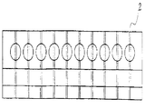
제1도는 본 발명의 일실시예에 의한 10 x 10 직교형 다중 단속 밸브 장치의 사시도이다. 제1도에서 보듯이, 몸체(1)에는 X축 방향과 Y축 방향으로 각각 n개 및 m개의 배열로 몸체(1)의 상부와 하부를 관통하는 10 x 10개의 유로(2)가 형성되어 있으며, 이 유로에 수직인 방향으로 몸체의 X축과 Y축의 측면에 각각 10개씩의 제어봉 구멍(3)이 통로로서 형성되어 있다. 이때, X축과 Y축의 측면에 형성된 제어봉 구멍(3)은 상호 수직 방향으로 분지되어 있다. 또한, 본 발명의 다중 단속 밸브 장치에는 제어봉(4)이 구비되는데, 이 제어봉(4)에는 몸체(1)에 형성된 유로(2)에 대응하는 간격으로 전기 유로(2)와 동일한 직경의 유로(2)가 형성되어 있다. 이때, 제어봉(4)은 원형, 사각형 또는 판형 등 다양한 형상으로 제조할 수 있는데, 각 제어봉에 걸리는 마찰력을 적게 하면서 용액의 누수가 일어나지 않도록 하고, 또한 제어봉의 유로에 머무는 용액의 양을 최소화하기 위하여, 제어봉의 두께를 작게하는 것이 바람직하다. 한편, 제어봉의 왕복 구동은 공압, 유압 및 전자석 등을 이용할 수 있으나, 빠른 시간 내에 정확히 유로를 개폐하기 위해서는 구동력이 강한 공압이나 유압을 이용하여 작동시키는 것이 바람직하다.1 is a perspective view of a 10 x 10 orthogonal multiple intermittent valve device according to an embodiment of the present invention. As shown in FIG. 1, the body 1 is formed with 10 x 10
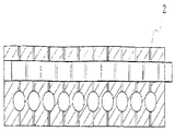
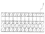
제2(a)도, 제2(b)도, 제2(c)도 및 제2(d)도는 본 발명의 일실시예에 의한 10 x 10 직교형 다중 단속 밸브 장치가 개폐된 상태를 X축과 Y축에서 절단하여 나타낸 단면도이다. 제2(a)도 및 제2(b)도는 본 발명의 다중 단속 밸브 장치가 닫힌 상태를 나타내는 것으로, 몸체의 상부와 하부를 관통하는 유로(2)와 몸체에 삽입된 제어봉의 유로가 상호 어긋나 있다. 제2(c)도 및 제2(d)도는 본 발명의 다중 단속 밸브 장치가 열린 상태를 나타내는 것으로, 몸체의 상부와 하부를 관통하는 유로(2)와 몸체에 삽입된 제어봉의 유로가 상호 일직선으로 일치된다.2 (a), 2 (b), 2 (c) and 2 (d) is a state in which the 10 x 10 orthogonal multiple intermittent valve device according to an embodiment of the present invention is opened and closed This is a cross-sectional view cut along the axis and the Y axis. 2 (a) and 2 (b) show a closed state of the multi-intermittent valve device of the present invention, in which the
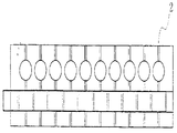
제3도는 본 발명의 다른 실시예에 의한 16 x 16 직교형 다중 단속 밸브 장치의 조립상태를 나타내는 사시도로서, 제1도의 10 x 10 직교형 다중 단속 밸브 장치와는 4장의 몸체가 사용되고, 제1도의 몸체에 형성된 제어봉 구멍대신에 전기 몸체가 다수 결합되어 형성된 틈이 제어봉의 통로로서 채용된다는 점에서 차이가 있다. 제3도에서 보듯이, 몸체에는 X축 방향과 Y축 방향으로 각각 n개 및 m개의 배열로 몸체(1′)의 상부와 하부를 관통하는 16 x 16개의 유로(2′)가 형성되어 있으며, 유로(2′) 내부 둘레에는 유액의 누출을 방지하기 위하여 팩킹(6)이 구비되어 있다(부분확대도 참조). 전기한 몸체(1′)는 4장이 구비되어 있고, 몸체(1′)들의 결합시 형성되는 몸체(1′)들 사이의 틈이 통로로서 채용되어, 몸체의 X축과 Y축의 측면에는 각 측면마다 8개씩, 총 32개의 평판 제어봉(6)이 전기 틈으로 삽입되며, 상부의 몸체 1장은 유로에 용액을 통과시키기 위한 도관을 포함하는 장치가 연결된다. 각각의 평판 제어봉에는 복동형 공압 실린더(5)가 결합되어 평판 제어봉의 위치를 제어한다.3 is a perspective view showing the assembled state of the 16 x 16 orthogonal multiple speed control valve device according to another embodiment of the present invention, four bodies are used with the 10 x 10 orthogonal multiple speed control valve device of FIG. There is a difference in that a gap formed by joining a plurality of electric bodies instead of the control rod holes formed in the body of FIG. As shown in FIG. 3, the body has 16 x 16 flow paths 2 'which penetrate the upper and lower portions of the body 1' in an array of n and m in the X and Y directions, respectively. The inner periphery of the flow path 2 'is provided with a
이하에서는, 본 발명의 다중 단속 밸브 장치의 작용 및 효과를 설명하고자 한다.Hereinafter, the operation and effects of the multi-intermittent valve device of the present invention will be described.
본 발명의 다중 단속 밸브 장치를 이용하여 모든 위치의 유로(2, 2′)들을 순차적으로 개폐하는 작동 순서는 다음과 같다; 우선, X 축의 n개의 제어봉(4, 4′)을 모두 닫힌 위치로 놓고, Y축의 m개의 제어봉(4, 4′) 중에서 첫 번째 열의 유로에 해당하는 제어봉(4, 4′)을 개방위치로 움직여 준 다음, X축의 첫 번째 열의 유로(2, 2′)에 해당하는 제어봉(4, 4′)을 개방위치로 움직여 유로(2, 2′)를 개방하고, 용액을 흘려 주고 나서, 일정 시간이 지난 다음에 바로 원위치하여 유로(2, 2′)를 폐쇄한다. 이렇게 함으로써, X축의 첫 번째 열에 있는 유로(2, 2′) 중에서 개방하고자 하는 유로(2, 2′)는 Y축의 제어봉(4, 4′)을 통해 개방된 유로(2, 2′)와 연결되어 용액을 통과시킬 수 있다. 이와 같은 방식으로, X축과 Y축에 있는 제어봉(4, 4′)을 조정하면서, 순차적으로 유로(2, 2′)를 개폐하여, 원하는 유로(2, 2′)를 통하여 유체를 통과시킬 수 있다.The operation sequence of sequentially opening and closing the
한편, 특정한 위치에 있는 한 개의 밸브만을 개폐하는 동작은 순차적인 것과는 상관없이 해당되는 열과 행의 밸브만을 개방 위치에 놓으면 된다.On the other hand, the operation of opening and closing only one valve at a specific position is required to place only the valve of the corresponding row and row in the open position irrespective of sequential.
이상에서 상세히 설명하였듯이, 본 발명은 X축과 Y축을 따라 각각 n개와 m개의 배열로 상부와 하부를 관통하도록 n x m개의 유로가 형성된 몸체의 X축과 Y축의 측면에 형성된 통로를 따라, 전기 몸체에 형성된 유로에 대응하는 간격으로 전기 유로와 동일한 직경의 유로가 n개 및 m개 형성된 제어봉이 밀착되게 삽입되어 직선운동을 하면서, 전기 몸체의 유로와 전기 몸체의 X축과 Y축의 측면에 삽입되는 제어봉의 유로가 상호 일치하여, 즉, 논리적으로 ‘AND’상태가 되었을 경우에만 유로를 통하여 유체가 통과하도록 하여, X축과 Y축의 n + m개의 조작변에 의하여 n x m개의 유로의 개폐를 조작할 수 있다.As described in detail above, the present invention is to the electric body along the passage formed on the sides of the X-axis and Y-axis of the body is formed with nxm flow paths to pass through the top and bottom in an array of n and m along the X and Y axes, respectively Control rods inserted into the flow path of the electric body and the sides of the X and Y axes of the electric body while being linearly inserted by inserting n and m control rods having the same diameter as the electric flow path at close intervals corresponding to the formed flow path. It is possible to operate the opening and closing of nxm flow paths by n + m operating sides of the X-axis and Y-axis so that the fluid passes through the flow path only when the flow paths coincide with each other. have.
지금까지, 첨부된 도면을 참조하여 본 발명을 상세히 설명하였으나, 이는 오로지 본 발명을 구체적으로 설명하기 위한 것으로서, 본 발명의 범위가 이에 국한되지 않는다는 것은 당업계에서 통상의 지식을 가진 자에게 있어서 자명할 것이다. 또한, 본 발명의 요지로부터 다양한 변형을 통해 몸체 및 제어봉에 형성된 n x m개의 유로를 상호일치시켜 논리적으로 ‘AND’ 상태가 되었을 경우에만 유로를 통하여 유체를 통과시키는 방식으로, n + m개의 제어밸브와 전자 조작변만으로 n x m개의 유로를 단속 조작할 수 있는 다양한 장치 및 방법은 모두 본 발명의 범주에 속한다고 보아야 할 것이다.So far, the present invention has been described in detail with reference to the accompanying drawings, which are only for explaining the present invention in detail, and the scope of the present invention is not limited thereto, and it is obvious to those skilled in the art. something to do. In addition, nxm flow paths formed in the body and the control rod through the various modifications from the gist of the present invention to coincide with the fluid through the flow path only when the logically 'AND' state, n + m control valves and Various devices and methods capable of intermittently manipulating nxm flow paths using only an electronic operating valve should be considered to belong to the scope of the present invention.
Claims (7)
Priority Applications (6)
| Application Number | Priority Date | Filing Date | Title |
|---|---|---|---|
| KR1019970053556A KR100279552B1 (en) | 1997-10-18 | 1997-10-18 | Multi-regulated valve device |
| US09/508,533 US6202687B1 (en) | 1997-10-18 | 1998-10-19 | Matrix multiple valve system |
| PCT/KR1998/000319 WO1999020387A1 (en) | 1997-10-18 | 1998-10-19 | Matrix multiple valve system |
| KR10-2000-7002940A KR100367745B1 (en) | 1997-10-18 | 1998-10-19 | Matrix Multiple Valve System |
| JP2000516770A JP3479043B2 (en) | 1997-10-18 | 1998-10-19 | Matrix type multiple intermittent valve device |
| AU97641/98A AU9764198A (en) | 1997-10-18 | 1998-10-19 | Matrix multiple valve system |
Applications Claiming Priority (1)
| Application Number | Priority Date | Filing Date | Title |
|---|---|---|---|
| KR1019970053556A KR100279552B1 (en) | 1997-10-18 | 1997-10-18 | Multi-regulated valve device |
Publications (1)
| Publication Number | Publication Date |
|---|---|
| KR100279552B1 true KR100279552B1 (en) | 2001-11-30 |
Family
ID=19523011
Family Applications (1)
| Application Number | Title | Priority Date | Filing Date |
|---|---|---|---|
| KR1019970053556A Expired - Fee Related KR100279552B1 (en) | 1997-10-18 | 1997-10-18 | Multi-regulated valve device |
Country Status (5)
| Country | Link |
|---|---|
| US (1) | US6202687B1 (en) |
| JP (1) | JP3479043B2 (en) |
| KR (1) | KR100279552B1 (en) |
| AU (1) | AU9764198A (en) |
| WO (1) | WO1999020387A1 (en) |
Families Citing this family (13)
| Publication number | Priority date | Publication date | Assignee | Title |
|---|---|---|---|---|
| US6485690B1 (en) * | 1999-05-27 | 2002-11-26 | Orchid Biosciences, Inc. | Multiple fluid sample processor and system |
| WO2002041988A1 (en) * | 2000-11-27 | 2002-05-30 | Union Carbide Chemicals & Plastics | Valved vessel system |
| USD465824S1 (en) | 2001-04-26 | 2002-11-19 | Kallista, Inc. | Flow distributor |
| US6637476B2 (en) | 2002-04-01 | 2003-10-28 | Protedyne Corporation | Robotically manipulable sample handling tool |
| US8220494B2 (en) * | 2002-09-25 | 2012-07-17 | California Institute Of Technology | Microfluidic large scale integration |
| JP2006501056A (en) * | 2002-09-25 | 2006-01-12 | カリフォルニア インスティテュート オブ テクノロジー | Micro fluid large scale integration |
| WO2004040001A2 (en) | 2002-10-02 | 2004-05-13 | California Institute Of Technology | Microfluidic nucleic acid analysis |
| US7249529B2 (en) * | 2003-03-28 | 2007-07-31 | Protedyne Corporation | Robotically manipulable sample handling tool |
| US7097070B2 (en) * | 2003-08-15 | 2006-08-29 | Protedyne Corporation | Method and apparatus for handling small volume fluid samples |
| US20070095413A1 (en) * | 2005-11-01 | 2007-05-03 | Georgia Tech Research Corporation | Systems and methods for controlling the flow of a fluidic medium |
| DE102009035292A1 (en) * | 2009-07-30 | 2011-02-03 | Karlsruher Institut für Technologie | Device for controlling the flow of fluids through microfluidic channels, methods of their operation and their use |
| KR101940325B1 (en) * | 2011-10-05 | 2019-01-18 | 가부시키가이샤 호리바 에스텍 | Fluid mechanism, support member constituting fluid mechanism and fluid control system |
| GB202005633D0 (en) * | 2020-04-17 | 2020-06-03 | Univ Court Univ Of Glasgow | Fluid handling device and methods |
Family Cites Families (7)
| Publication number | Priority date | Publication date | Assignee | Title |
|---|---|---|---|---|
| FR93701E (en) * | 1967-04-03 | 1969-05-09 | Legris Fils | Fluid and integrated circuit programmer. |
| US3744376A (en) * | 1972-03-16 | 1973-07-10 | Synalloy Corp | Pressure fluid control arrangement and method |
| US3765441A (en) * | 1972-03-22 | 1973-10-16 | Sun Oil Co Pennsylvania | Fluid manifolding arrangement |
| US3881513A (en) * | 1974-01-25 | 1975-05-06 | Sun Oil Co Pennsylvania | Three-coordinate fluid manifold |
| DE4206488C2 (en) * | 1992-03-02 | 1993-12-23 | Deutsches Krebsforsch | Device for carrying out chemical reactions taking place simultaneously or sequentially |
| EP0653965B1 (en) | 1992-07-06 | 1996-05-15 | Beckman Instruments, Inc. | Fluid delivery system uitlizing multiple port valve |
| IL123662A (en) * | 1995-09-22 | 2001-01-28 | Berlex Lab | Apparatus and process for multiple chemical reactions |
-
1997
- 1997-10-18 KR KR1019970053556A patent/KR100279552B1/en not_active Expired - Fee Related
-
1998
- 1998-10-19 AU AU97641/98A patent/AU9764198A/en not_active Abandoned
- 1998-10-19 US US09/508,533 patent/US6202687B1/en not_active Expired - Lifetime
- 1998-10-19 WO PCT/KR1998/000319 patent/WO1999020387A1/en not_active Ceased
- 1998-10-19 JP JP2000516770A patent/JP3479043B2/en not_active Expired - Fee Related
Also Published As
| Publication number | Publication date |
|---|---|
| JP2002500943A (en) | 2002-01-15 |
| WO1999020387A1 (en) | 1999-04-29 |
| AU9764198A (en) | 1999-05-10 |
| US6202687B1 (en) | 2001-03-20 |
| JP3479043B2 (en) | 2003-12-15 |
Similar Documents
| Publication | Publication Date | Title |
|---|---|---|
| KR100279552B1 (en) | Multi-regulated valve device | |
| EP2837864B1 (en) | Multi-directional selector valve | |
| US6431212B1 (en) | Valve for use in microfluidic structures | |
| US6739576B2 (en) | Microfluidic flow control device with floating element | |
| US6916113B2 (en) | Devices and methods for fluid mixing | |
| KR101922627B1 (en) | Multiplexor for control of flow in microfluidics chip and microfluidics chip assembly | |
| EP2837863B1 (en) | Valve structure | |
| JP4378067B2 (en) | A valve that allows the fluid in the analysis pack to be directed, a pack that includes the valve, and a device that allows the use of multiple packs that include such a valve | |
| US20030196695A1 (en) | Microfluidic flow control devices | |
| MXPA04007698A (en) | Poppet valve having an improved valve seat. | |
| US5320139A (en) | Fluid delivery system | |
| EP0134185B1 (en) | Modular directional valve | |
| US5707217A (en) | Pressure transfer modules | |
| US4922963A (en) | Hydraulic servovalve | |
| US11193600B2 (en) | Ultra-low carryover solenoid valve | |
| JP3917547B2 (en) | Fluid pressure valve unit | |
| KR20010024171A (en) | Matrix multiple valve system | |
| WO2018221576A1 (en) | Microfluidic device and microfluidic device system | |
| Wang et al. | A Nonvolatile Switchable-polarity EPM Valve | |
| US20130105525A1 (en) | Dispensing module and method of dispensing with a pneumatic actuator | |
| US12115530B2 (en) | On-board reagent storage in a fluid processing device | |
| JP4712645B2 (en) | Sliding solenoid valve | |
| CN109074062A (en) | Mechanically Driven Sequencing Manifold | |
| JP2019144164A (en) | Fluid handling device | |
| JP2025064215A (en) | Gate valve, chamber with gate valve, and chemical heat storage system |
Legal Events
| Date | Code | Title | Description |
|---|---|---|---|
| A201 | Request for examination | ||
| G15R | Request for early publication | ||
| PA0109 | Patent application |
St.27 status event code: A-0-1-A10-A12-nap-PA0109 |
|
| PA0201 | Request for examination |
St.27 status event code: A-1-2-D10-D11-exm-PA0201 |
|
| R17-X000 | Change to representative recorded |
St.27 status event code: A-3-3-R10-R17-oth-X000 |
|
| PG1501 | Laying open of application |
St.27 status event code: A-1-1-Q10-Q12-nap-PG1501 |
|
| N231 | Notification of change of applicant | ||
| PN2301 | Change of applicant |
St.27 status event code: A-3-3-R10-R13-asn-PN2301 St.27 status event code: A-3-3-R10-R11-asn-PN2301 |
|
| E902 | Notification of reason for refusal | ||
| PE0902 | Notice of grounds for rejection |
St.27 status event code: A-1-2-D10-D21-exm-PE0902 |
|
| P11-X000 | Amendment of application requested |
St.27 status event code: A-2-2-P10-P11-nap-X000 |
|
| P13-X000 | Application amended |
St.27 status event code: A-2-2-P10-P13-nap-X000 |
|
| PN2301 | Change of applicant |
St.27 status event code: A-3-3-R10-R13-asn-PN2301 St.27 status event code: A-3-3-R10-R11-asn-PN2301 |
|
| PN2301 | Change of applicant |
St.27 status event code: A-3-3-R10-R13-asn-PN2301 St.27 status event code: A-3-3-R10-R11-asn-PN2301 |
|
| E701 | Decision to grant or registration of patent right | ||
| PE0701 | Decision of registration |
St.27 status event code: A-1-2-D10-D22-exm-PE0701 |
|
| GRNT | Written decision to grant | ||
| PR0701 | Registration of establishment |
St.27 status event code: A-2-4-F10-F11-exm-PR0701 |
|
| PR1002 | Payment of registration fee |
St.27 status event code: A-2-2-U10-U11-oth-PR1002 Fee payment year number: 1 |
|
| R18-X000 | Changes to party contact information recorded |
St.27 status event code: A-5-5-R10-R18-oth-X000 |
|
| PG1601 | Publication of registration |
St.27 status event code: A-4-4-Q10-Q13-nap-PG1601 |
|
| R18-X000 | Changes to party contact information recorded |
St.27 status event code: A-5-5-R10-R18-oth-X000 |
|
| PR1001 | Payment of annual fee |
St.27 status event code: A-4-4-U10-U11-oth-PR1001 Fee payment year number: 4 |
|
| PR1001 | Payment of annual fee |
St.27 status event code: A-4-4-U10-U11-oth-PR1001 Fee payment year number: 5 |
|
| PR1001 | Payment of annual fee |
St.27 status event code: A-4-4-U10-U11-oth-PR1001 Fee payment year number: 6 |
|
| PR1001 | Payment of annual fee |
St.27 status event code: A-4-4-U10-U11-oth-PR1001 Fee payment year number: 7 |
|
| R18-X000 | Changes to party contact information recorded |
St.27 status event code: A-5-5-R10-R18-oth-X000 |
|
| R18-X000 | Changes to party contact information recorded |
St.27 status event code: A-5-5-R10-R18-oth-X000 |
|
| PR1001 | Payment of annual fee |
St.27 status event code: A-4-4-U10-U11-oth-PR1001 Fee payment year number: 8 |
|
| PR1001 | Payment of annual fee |
St.27 status event code: A-4-4-U10-U11-oth-PR1001 Fee payment year number: 9 |
|
| PR1001 | Payment of annual fee |
St.27 status event code: A-4-4-U10-U11-oth-PR1001 Fee payment year number: 10 |
|
| PR1001 | Payment of annual fee |
St.27 status event code: A-4-4-U10-U11-oth-PR1001 Fee payment year number: 11 |
|
| PR1001 | Payment of annual fee |
St.27 status event code: A-4-4-U10-U11-oth-PR1001 Fee payment year number: 12 |
|
| FPAY | Annual fee payment |
Payment date: 20121011 Year of fee payment: 13 |
|
| PR1001 | Payment of annual fee |
St.27 status event code: A-4-4-U10-U11-oth-PR1001 Fee payment year number: 13 |
|
| PN2301 | Change of applicant |
St.27 status event code: A-5-5-R10-R13-asn-PN2301 St.27 status event code: A-5-5-R10-R11-asn-PN2301 |
|
| FPAY | Annual fee payment |
Payment date: 20130904 Year of fee payment: 14 |
|
| PR1001 | Payment of annual fee |
St.27 status event code: A-4-4-U10-U11-oth-PR1001 Fee payment year number: 14 |
|
| FPAY | Annual fee payment |
Payment date: 20140917 Year of fee payment: 15 |
|
| PR1001 | Payment of annual fee |
St.27 status event code: A-4-4-U10-U11-oth-PR1001 Fee payment year number: 15 |
|
| LAPS | Lapse due to unpaid annual fee | ||
| PC1903 | Unpaid annual fee |
St.27 status event code: A-4-4-U10-U13-oth-PC1903 Not in force date: 20151102 Payment event data comment text: Termination Category : DEFAULT_OF_REGISTRATION_FEE |
|
| PC1903 | Unpaid annual fee |
St.27 status event code: N-4-6-H10-H13-oth-PC1903 Ip right cessation event data comment text: Termination Category : DEFAULT_OF_REGISTRATION_FEE Not in force date: 20151102 |
|
| P22-X000 | Classification modified |
St.27 status event code: A-4-4-P10-P22-nap-X000 |
|
| R18-X000 | Changes to party contact information recorded |
St.27 status event code: A-5-5-R10-R18-oth-X000 |
|
| R18-X000 | Changes to party contact information recorded |
St.27 status event code: A-5-5-R10-R18-oth-X000 |