KR100259446B1 - Disk apparatus and servo-pattern write system - Google Patents
Disk apparatus and servo-pattern write system Download PDFInfo
- Publication number
- KR100259446B1 KR100259446B1 KR1019970708341A KR19970708341A KR100259446B1 KR 100259446 B1 KR100259446 B1 KR 100259446B1 KR 1019970708341 A KR1019970708341 A KR 1019970708341A KR 19970708341 A KR19970708341 A KR 19970708341A KR 100259446 B1 KR100259446 B1 KR 100259446B1
- Authority
- KR
- South Korea
- Prior art keywords
- servo
- area
- signal
- disc
- recorded
- Prior art date
Links
Images


Classifications
-
- G—PHYSICS
- G11—INFORMATION STORAGE
- G11B—INFORMATION STORAGE BASED ON RELATIVE MOVEMENT BETWEEN RECORD CARRIER AND TRANSDUCER
- G11B5/00—Recording by magnetisation or demagnetisation of a record carrier; Reproducing by magnetic means; Record carriers therefor
- G11B5/48—Disposition or mounting of heads or head supports relative to record carriers ; arrangements of heads, e.g. for scanning the record carrier to increase the relative speed
- G11B5/58—Disposition or mounting of heads or head supports relative to record carriers ; arrangements of heads, e.g. for scanning the record carrier to increase the relative speed with provision for moving the head for the purpose of maintaining alignment of the head relative to the record carrier during transducing operation, e.g. to compensate for surface irregularities of the latter or for track following
- G11B5/596—Disposition or mounting of heads or head supports relative to record carriers ; arrangements of heads, e.g. for scanning the record carrier to increase the relative speed with provision for moving the head for the purpose of maintaining alignment of the head relative to the record carrier during transducing operation, e.g. to compensate for surface irregularities of the latter or for track following for track following on disks
- G11B5/59633—Servo formatting
- G11B5/59644—Acquisition or selection of servo format from a system reference
-
- G—PHYSICS
- G11—INFORMATION STORAGE
- G11B—INFORMATION STORAGE BASED ON RELATIVE MOVEMENT BETWEEN RECORD CARRIER AND TRANSDUCER
- G11B5/00—Recording by magnetisation or demagnetisation of a record carrier; Reproducing by magnetic means; Record carriers therefor
- G11B5/48—Disposition or mounting of heads or head supports relative to record carriers ; arrangements of heads, e.g. for scanning the record carrier to increase the relative speed
- G11B5/54—Disposition or mounting of heads or head supports relative to record carriers ; arrangements of heads, e.g. for scanning the record carrier to increase the relative speed with provision for moving the head into or out of its operative position or across tracks
- G11B5/55—Track change, selection or acquisition by displacement of the head
- G11B5/5521—Track change, selection or acquisition by displacement of the head across disk tracks
- G11B5/5526—Control therefor; circuits, track configurations or relative disposition of servo-information transducers and servo-information tracks for control thereof
-
- G—PHYSICS
- G11—INFORMATION STORAGE
- G11B—INFORMATION STORAGE BASED ON RELATIVE MOVEMENT BETWEEN RECORD CARRIER AND TRANSDUCER
- G11B5/00—Recording by magnetisation or demagnetisation of a record carrier; Reproducing by magnetic means; Record carriers therefor
- G11B5/48—Disposition or mounting of heads or head supports relative to record carriers ; arrangements of heads, e.g. for scanning the record carrier to increase the relative speed
- G11B5/58—Disposition or mounting of heads or head supports relative to record carriers ; arrangements of heads, e.g. for scanning the record carrier to increase the relative speed with provision for moving the head for the purpose of maintaining alignment of the head relative to the record carrier during transducing operation, e.g. to compensate for surface irregularities of the latter or for track following
- G11B5/596—Disposition or mounting of heads or head supports relative to record carriers ; arrangements of heads, e.g. for scanning the record carrier to increase the relative speed with provision for moving the head for the purpose of maintaining alignment of the head relative to the record carrier during transducing operation, e.g. to compensate for surface irregularities of the latter or for track following for track following on disks
- G11B5/59627—Aligning for runout, eccentricity or offset compensation
-
- G—PHYSICS
- G11—INFORMATION STORAGE
- G11B—INFORMATION STORAGE BASED ON RELATIVE MOVEMENT BETWEEN RECORD CARRIER AND TRANSDUCER
- G11B5/00—Recording by magnetisation or demagnetisation of a record carrier; Reproducing by magnetic means; Record carriers therefor
- G11B5/48—Disposition or mounting of heads or head supports relative to record carriers ; arrangements of heads, e.g. for scanning the record carrier to increase the relative speed
- G11B5/58—Disposition or mounting of heads or head supports relative to record carriers ; arrangements of heads, e.g. for scanning the record carrier to increase the relative speed with provision for moving the head for the purpose of maintaining alignment of the head relative to the record carrier during transducing operation, e.g. to compensate for surface irregularities of the latter or for track following
- G11B5/596—Disposition or mounting of heads or head supports relative to record carriers ; arrangements of heads, e.g. for scanning the record carrier to increase the relative speed with provision for moving the head for the purpose of maintaining alignment of the head relative to the record carrier during transducing operation, e.g. to compensate for surface irregularities of the latter or for track following for track following on disks
- G11B5/59683—Disposition or mounting of heads or head supports relative to record carriers ; arrangements of heads, e.g. for scanning the record carrier to increase the relative speed with provision for moving the head for the purpose of maintaining alignment of the head relative to the record carrier during transducing operation, e.g. to compensate for surface irregularities of the latter or for track following for track following on disks for magnetoresistive heads
Abstract
MR(자기 저항) 소자를 재생 소자로서 사용한 디스크 장치이며, 서보 영역과 데이터 영역이 구분되어 구성된 디스크를 갖는 디스크 장치에 있어서, 디스크상에 발생하는 돌기물로 인한 재생 에러, 이른바 서멀 애스페리티(thermal asperity)의 재생 에러를 방지하는 구성으로서, 특히 서보 영역에서의 그레이 코드 직전에 발생하는 서멀 애스페리티에 의해, 그레이 코드의 스타트 비트의 판독 에러를 방지하고, 이레이즈 영역을 검출하는 구성을 제공한다. 본 발명의 구성은 그레이 코드의 개시 위치에 있는 스타트 비트의 재생 신호의 극성이, 서멀 애스페리티에 의해 MR 소자가 발생하는 신호의 극성과 반대가 되도록 서보 패턴을 형성하고, 신호 판독을 다른 극성을 교대로 검출하여 판독하는 히스테리시스 비교기(hysteresis comparator)를 갖는 채널 회로를 사용하여, 서멀 애스페리티로 인한 오신호 판독이 실행되지 않도록 형성하여 재생 에러를 방지하였다.A disc device using an MR (magnetic resistance) element as a reproducing element, the disc device having a disc composed of a servo area and a data area, comprising: a reproducing error due to projections occurring on the disc, so-called thermal aperity ( Provides a configuration for preventing a playback error of thermal asperity, especially a thermal aperity occurring immediately before the gray code in the servo area to prevent a read error of the start bit of the gray code and to detect an erased area. do. The configuration of the present invention forms a servo pattern so that the polarity of the reproduction signal of the start bit at the start position of the gray code is opposite to the polarity of the signal generated by the MR element due to the thermal asperity, and the signal readout is made to have a different polarity. Using a channel circuit having a hysteresis comparator that alternately detects and reads out, a false signal reading due to thermal aperity is formed so as not to be executed to prevent a reproduction error.
Description
자기 디스크 장치는 자기 변화에 의해 디스크 표면에 데이터를 기록하거나 판독하는 장치이다. 데이터가 기록된 트랙의 소정 위치에 변환기가 위치되어, 고속 회전하는 디스크의 트랙에 기록된 정보를 판독하거나 기록한다. 헤드는 디스크 표면으로부터 약간 떨어져 소정의 트랙위에 위치된다. 최근의 변환 헤드 중의 하나로서 자기 저항(MR) 변환 헤드가 채용되고 있다. 이것은 그 출력 저항이 자계의 변화와 함께 변화하는 것이며, 이 저항 변화가 MR 소자에 소정의 전류를 흐르게 함으로써, 직류 전압 신호로 변환되어 데이터의 판독을 실행하는 것이다.A magnetic disk device is a device for recording or reading data on a disk surface by magnetic change. The transducer is located at a predetermined position of the track on which the data is recorded, so as to read or record the information recorded on the track of the high-speed rotating disc. The head is located on a predetermined track slightly away from the disk surface. As one of the recent conversion heads, a magnetoresistive (MR) conversion head is employed. This is because the output resistance changes with the change in the magnetic field, and this change in resistance causes a predetermined current to flow through the MR element, which is converted into a DC voltage signal to read data.
그러나, 이 저항 변화를 판독하는 방식에서의 판독 동작상의 문제 중의 하나로서 서멀 애스페리티가 있다. 서멀 애스페리티란, 디스크상에 발생한 돌기물이 판독 헤드에 충돌하여 MR 소자에 온도 변화에 의한 저항 변화를 발생시키는 것으로 여겨진다. 이에 의하여, 이상 신호가 발생하는 것이다.However, one of the problems in the read operation in the method of reading this resistance change is thermal asperity. The thermal aperity is considered to cause projections generated on the disk to impinge on the read head and to cause resistance changes due to temperature changes in the MR element. As a result, an abnormal signal is generated.
서멀 애스페리티라고 지칭되는 현상은 스트립(strip) 온도를 국부적으로 100도 이상 상승시키는 경우가 있다. 이 온도 상승의 원인은 MR 스트라이프(MR stripe)를 포함하는 헤드 부분과 디스크면의 돌기물간의 기계적인 충돌이다. 매체에서의 정상적인 판독에 의한 자계 변화에 의한 MR 헤드의 저항 변화는 MR 스트라이프의 1 % 미만이므로, 서멀 애스페리티가 발생한 경우의 온도 상승에 기인하는 신호 변화는 정상적인 판독 신호에 의한 저항 변화를 크게 초과하게 되어, 정상적인 데이터 판독이 저해된다.The phenomenon called thermal aperity sometimes raises the strip temperature locally by 100 degrees or more. The cause of this temperature rise is a mechanical collision between the head portion containing the MR stripe and the projection on the disk surface. Since the MR head's resistance change due to the magnetic field change due to the normal reading in the medium is less than 1% of the MR stripe, the signal change caused by the temperature rise in the case of thermal aperity greatly increases the resistance change due to the normal read signal. Exceeding, normal data reading is inhibited.
판독 데이터에 대한 서멀 애스페리티 대책으로서의 종래의 방법은 서멀 애스페리티일 것으로 판단되는 급격한 신호 변화를 판독하였을 때, 그 판독 신호에 대해 적당한 변경을 가하여 판독 데이터로서 이용 가능하게 하는 것, 혹은 ECC 등의 적당한 에러 정정 방법에 의해 판독 신호의 정정을 실행하는 것 등이 있었다. 그러나, 이들은 외부에 새로운 하드웨어를 부가할 필요가 있거나, 또한 ECC 등에서는 회복이 불가능한 큰 버스트 오류(burst error)의 경우에는 정정 불가능하게 되어, 최종적으로는 판독 불가능한 하드 에러로서 처리하지 않을 수 없는 등의 결함이 있어, 서멀 애스페리티의 충분한 해결이 될 수 없었다.The conventional method as a countermeasure against thermal aperity for read data is to make an appropriate change to the read signal and make it available as read data when a sudden signal change that is determined to be thermal aperity is read, or the like. Correction of the read signal by a suitable error correction method. However, they need to add new hardware to the outside, and in the case of large burst errors that cannot be recovered by ECC, etc., they cannot be corrected, and finally they cannot be treated as hard errors that cannot be read. There was a defect, and it was not possible to sufficiently solve the thermal aperity.
본 발명은 자기 디스크 장치에서의 재생 에러 처리 분야에 관한 것으로서, 특히 서보 영역의 서멀 애스페리티(thermal asperity)로 인한 재생 에러의 대책에 관한 것이다.BACKGROUND OF THE INVENTION 1. Field of the Invention [0001] The present invention relates to the field of playback error processing in magnetic disk devices, and more particularly to countering playback errors due to thermal asperity in the servo region.
도 1은 본 발명이 적용되는 하드 디스크 장치의 블록도.1 is a block diagram of a hard disk device to which the present invention is applied.
도 2는 자기 디스크에 기록된 서보 영역을 도시한 도면.2 shows a servo area recorded on a magnetic disk.
도 3은 자기 디스크의 그레이 코드를 설명한 도면.3 is a view for explaining a gray code of a magnetic disk;
도 4는 서보 영역에서의 신호 패턴, 판독 신호 입력 파형 및 입력 파형으로부터 얻어지는 피크 검출 파형.4 is a peak detection waveform obtained from a signal pattern, a read signal input waveform, and an input waveform in the servo region.
도 5는 데이터 기록 후의 서보 영역을 도시한 도면.5 is a diagram showing a servo area after data recording.
도 6은 종래예의 서보 영역에서의 서멀 애스페리티가 발생한 경우에서의 신호 패턴, 판독 신호 입력 파형 및 입력 파형으로부터 얻어지는 피크 검출 파형.Fig. 6 is a peak detection waveform obtained from a signal pattern, a read signal input waveform, and an input waveform when a thermal aperity occurs in the servo region of the conventional example.
도 7은 본 발명의 서보 영역에서의 서멀 애스페리티가 발생한 경우에서의 신호 패턴, 판독 신호 입력 파형 및 입력 파형으로부터 얻어지는 피크 검출 파형.Fig. 7 is a peak detection waveform obtained from a signal pattern, a read signal input waveform, and an input waveform in the case where thermal aperity occurs in the servo region of the present invention.
도 8은 MR 소자 자화 방향과 디스크의 자화 패턴의 관계를 도시한 도면.8 is a diagram showing a relationship between an MR element magnetization direction and a magnetization pattern of a disk;
본 발명의 목적은 서멀 애스페리티에 의한 판독 에러를 효과적으로 방지하는 구성을 갖는 디스크 장치를 제공하고, 또 그 방법을 제공하는 것이다.SUMMARY OF THE INVENTION An object of the present invention is to provide a disk device having a configuration which effectively prevents a read error due to thermal aperity, and to provide a method thereof.
본 발명의 특징은 디스크에 대한 헤드의 위치 정보인 서보 정보 중에 서멀 애스페리티가 출현한 경우에, 이 서멀 애스페리티로 인한 판독 신호를 무시할 수 있게 한 것이다.It is a feature of the present invention that a read signal due to this thermal aparity can be ignored when the thermal aperity appears in the servo information which is the positional information of the head with respect to the disc.
본 발명은 서보 정보 중의 서보 신호 개시(開始) 위치의 서보 패드 영역과 디스크상의 트랙 위치 등을 나타내는 그레이 코드(Gray code)의 사이에서 서멀 애스페리티가 발생한 경우에 서멀 애스페리티로 인한 신호를 그레이 코드의 스타트 비트라고 인식하는 것을 방지하고, 서보 패드 영역과 스타트 비트간에 존재하는 이레이즈 영역(Erase Area)의 확실한 검출을 가능하게 한 것이다. 이것을 실현하기 위하여 서보 패드의 최종 신호의 입력 파형의 극성을 서멀 애스페리티에 의해 생기는 파형의 극성과 반드시 동일해지도록 서보 패드 신호를 기록함과 동시에, 그레이 코드의 개시 위치를 나타내는 스타트 비트를 이들의 역극성(逆極性)으로서 기록하도록 구성하고, 이들 신호를 판독함에 있어 역극성의 신호 피크를 검색하고, 이것을 검출하는 모드, 예를 들면 히스테리시스 비교기 모드(hysteresis comparator mode)를 사용하여, 교호(交互) 극성 신호를 판독하도록 한 것이다. 따라서, 동일 극성의 신호가 연속하여 판독되었을 때는, 이 신호는 서멀 애스페리티에 기인하는 것이 되어 무시된다. 이로써, 서멀 애스페리티에 후속하는 바른 신호를 판독할 수 있게 된다.The present invention provides a signal due to a thermal aparity when a thermal aparity occurs between a servo pad area at a servo signal start position in a servo information and a gray code indicating a track position on a disk or the like. It is possible to prevent the recognition of the gray code as a start bit and to reliably detect the erase area existing between the servo pad area and the start bit. To realize this, the servo pad signal is written so that the polarity of the input waveform of the final signal of the servo pad is the same as the polarity of the waveform generated by the thermal aperity, and the start bit indicating the start position of the gray code is reversed. It is configured to record as polarity, and alternately using a mode for searching for and detecting reverse polarity signal peaks in reading these signals, for example, using a hysteresis comparator mode. The polarity signal is read. Therefore, when signals of the same polarity are read continuously, this signal is attributed to the thermal asperity and is ignored. This makes it possible to read the correct signal following the thermal aperity.
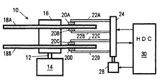
도 1은 본 발명이 적용되는 하드 디스크 장치(HDD)의 예이다. 도 1에 도시한 바와 같이 디스크 장치(10)는 디스크부(11) 및 로컬 CPU를 구비한 하드 디스크 콘트롤러(HDC)로 구성되어 있다. 디스크부(11)는 샤프트(12)를 고속으로 회전시키는 디스크 구동 장치(14)를 구비하고 있다. 샤프트(12)에는 서로의 축선이 일치하도록 원통상의 지지체(16)가 설치되어 있고, 지지체(16)의 외주면에는 1개 이상의 정보 기록용 디스크(18A, 18B)가 소정 간격으로 설치되어 있다. 디스크 구동 장치(14)에 의해 샤프트(12)가 회전되면 디스크(18A, 18B)는 지지체(16)와 일체적으로 회전된다.1 is an example of a hard disk device (HDD) to which the present invention is applied. As shown in Fig. 1, the
각 디스크의 면에 대향하는 형태로 신호 변환기(20A, 20B, 20C, 20D)가 액세스 아암(22A, 22B, 22C, 22D)에 지지되어 배치되어 있다. 액세스 아암(22A∼D)은 샤프트(24)를 통해 신호 변환기 구동 장치(28)에 설치되며, 그 회동에 의해, 신호 변환기(20A∼D)는 디스크의 소정 부위에 위치된다. 디스크 구동 장치(14) 및 신호 변환기 구동 장치(28)는 HDC(30)에 접속되며, 그 회전수, 속도 등이 제어된다. HDC(30)은 호스트에 접속 가능하다.The
하드 디스크, 플렉시블 디스크(flexible disk) 등의 자기 디스크에는 동심원 형태로 데이터 트랙이 형성되어 있다. 자기 디스크에 대한 정보의 판독 또는 기록은, 자기 디스크를 회전시킴과 동시에, 자기 헤드를 대체로 자기 디스크의 직경 방향에 따라 이동시켜 특정 데이터 트랙에 위치[이른바 시크 동작(seek operation)]시킨 후 행해진다. 자기 헤드를 특정 데이터 트랙에 위치시키는 것은, 다음에 설명하는 바와 같이, 자기 디스크에 미리 기록된 헤드 위치 식별 정보 및 버스트 패턴을 자기 헤드에 의해 각각 판독함으로써 행해진다.Magnetic tracks such as hard disks and flexible disks have data tracks formed in concentric circles. The reading or writing of information on the magnetic disk is performed after the magnetic disk is rotated and the magnetic head is generally moved along the radial direction of the magnetic disk to position it on a specific data track (so-called seek operation). . Positioning the magnetic head on a specific data track is performed by reading the head position identification information and the burst pattern previously recorded on the magnetic disk by the magnetic head, respectively, as described below.
도 2에는 자기 디스크상에 기록되는 헤드 위치 식별 정보 및 버스트 패턴의 일부를 도시한다. 도 2에서, 자기 디스크는 원주 방향[도 2의 화살표(F) 방향]에 따라 회전하며, 도시하지 않은 자기 헤드는 대체로 자기 디스크의 직경 방향[도 2의 화살표(G) 방향]에 따라 이동한다. 자기 디스크에는 데이터가 기록되는 복수의 데이터 트랙(100A, 100B, 100C, …)가 동심원 형태로 형성되어 있다. 각 데이터 트랙은 원주 방향을 따라 구분되어 있고, 이 데이터 트랙이 구분된 간격 부분에 식별 정보 기록 영역(102) 및 버스트 패턴 기록 영역(104)이 형성되어 있다.2 shows a part of the head position identification information and the burst pattern recorded on the magnetic disk. In FIG. 2, the magnetic disk rotates in the circumferential direction (direction of arrow F in FIG. 2), and the magnetic head, not shown, generally moves in the radial direction of the magnetic disk (in the direction of arrow G in FIG. 2). . In the magnetic disk, a plurality of
각 데이터 트랙에는 각 데이터 트랙을 식별하기 위한 트랙 어드레스가 미리 부여되어 있고, 상기 식별 정보 기록 영역(102)에는 각 데이터 트랙의 트랙 어드레스를 그레이 코드(Cyclic binary code : 순회 2진 부호)로 각각 나타낸 소정 비트수의 식별 정보가 각 데이터 트랙에 대응하여 원주 방향을 따라 기록되어 있다. 또한, 버스트 패턴 기록 영역(104)에는, 신호가 기록된 영역[도 2에서는 해칭(빗금)으로 표시함]이 각각 직경 방향을 따라 배열된 복수개(도 2에서는 4개)의 버스트 패턴 열(106A, 106B, 106C, 106D)이 기록되어 있다.Each data track is pre-assigned with a track address for identifying each data track, and in the identification
자기 헤드를 소정의 데이터 트랙에 위치시키는 경우에는, 전술한 바와 같이 자기 디스크를 회전시킴과 동시에, 자기 헤드를 대체로 자기 디스크의 직경 방향을 따르도록 이동시키고, 자기 디스크의 회전에 의해 식별 정보 기록 영역(102)이 자기 헤드에 대응할 때마다, 자기 헤드로부터 출력되는 식별 정보 판독 신호에 기초하여, 현재의 자기 헤드의 위치로서, 자기 헤드가 대응하고 있는 데이터 트랙의 트랙 어드레스를 산출한다. 식별 정보는 1 비트의 데이터의 기록 길이가 미리 정해져 있고, 트랙 어드레스를 나타내는 그레이 코드의 각 비트값이 "0"인지 "1"인지에 따라, 각 비트에 대응하는 N 또는 S로 자화되는 부분의 위치가 다르게 기록된다.In the case where the magnetic head is located on a predetermined data track, as described above, the magnetic disk is rotated and the magnetic head is generally moved along the radial direction of the magnetic disk, and the identification information recording area is caused by the rotation of the magnetic disk. Each
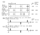
예를 들면, 도 3의 (a)에 도시한 데이터 트랙(N)의 식별 정보 기록 영역을 자기 헤드가 통과하면, 식별 정보 판독 신호로서 도 3의 (b)에 도시한 바와 같이 N 또는 S로 자화된 부분에서 펄스가 생기며, 그 펄스에 따른 신호가 자기 헤드로부터 출력된다. 또한, 도 3의 (a)에 도시한 데이터 트랙(N+1)의 식별 정보 기록 영역을 자기 헤드가 통과하면, 식별 정보 판독 신호로서 도 3의 (c)에 도시한 바와 같이 N 또는 S로 자화된 부분에서 펄스가 생기며, 그 펄스에 따른 신호가 자기 헤드로부터 출력된다. 이들의 식별 정보 판독 신호의 펄스의 위치에 기초하여, 식별 정보 기록 영역(102)에 기록된 식별 정보로서의 그레이 코드의 값을 판별할 수 있으며, 판별한 그레이 코드를 바이너리 코드로 변환함으로써 트랙 어드레스를 얻을 수 있다.For example, when the magnetic head passes through the identification information recording area of the data track N shown in Fig. 3A, it is identified as N or S as the identification information read signal as shown in Fig. 3B. A pulse is generated at the magnetized portion, and a signal according to the pulse is output from the magnetic head. In addition, when the magnetic head passes through the identification information recording area of the data track N + 1 shown in Fig. 3A, the identification information read signal is N or S as shown in Fig. 3C. A pulse is generated at the magnetized portion, and a signal according to the pulse is output from the magnetic head. Based on the position of the pulse of these identification information readout signals, the value of the gray code as the identification information recorded in the identification
도 3의 (b)의 펄스로부터는 그레이 코드(100)가 판독되며, 변환된 바이너리 코드(111)가 얻어지고, 도 3의 (c)의 펄스로부터는 그레이 코드(000)이 판독되며, 변환된 바이너리 코드(000)가 얻어진다.The
자기 헤드가 목표 데이터 트랙에 대응하였다고 판단하면, 자기 헤드에 의해 버스트 패턴 기록 영역(104)의 복수개의 버스트 패턴의 열(列)을 각각 판독함으로써 얻어지는 복수의 신호에 기초하여, 자기 헤드의 위치에 따라 선형적으로 레벨이 변화하는 위치 검출 신호를 생성하고, 이 위치 검출 신호에 기초하여, 자기 헤드의 간극(gap)의 중심이 목표 데이터 트랙의 폭 방향 중심부에 위치하도록 자기 헤드를 위치시킨다.If it is determined that the magnetic head corresponds to the target data track, the magnetic head is located at the position of the magnetic head based on a plurality of signals obtained by reading the rows of the plurality of burst patterns of the burst
그런데, 자기 디스크는, 매체의 결함, 전기적 노이즈 등에 기인하는 재생 에러의 발생이라는 문제가 있다. 최근, 재생 소자로서 MR(MAGNETO-RESISTIVE) 헤드(자기 저항 소자 헤드)를 사용한 디스크 장치가 고용량의 디스크 장치로서 주목되고 있다. 이 헤드를 사용한 디스크 장치에서는 서멀 애스페리티에 의한 재생 에러라는 문제가 새롭게 부상하기 시작했다. MR 소자는 디스크에 기록된 정보인 자기 변화를 소자가 검지하고, 이것을 전기 저항의 변화로서 판독하는(MR 효과) 것이다.By the way, the magnetic disk has a problem of generation of a reproduction error due to a defect in a medium, electrical noise, or the like. In recent years, a disk device using an MR (MAGNETO-RESISTIVE) head (magnetic resistance element head) as a reproducing element has attracted attention as a high capacity disk device. In the disk apparatus using this head, the problem of the reproduction error by the thermal aperity started to emerge newly. The MR element detects a magnetic change, which is information recorded on the disk, and reads it as a change in electrical resistance (MR effect).
서멀 애스페리티란, 디스크상에 어떠한 원인, 예를 들면 먼지, 부식 등을 생각할 수 있으며, 여러 가지의 원인에 의해 발생하는 돌기로서, 이 돌기가 MR 소자를 갖는 헤드의 구성체에 충돌하여 소자의 온도를 상승시키고, 저항 변화를 발생시켜 재생 에러를 발생시키는 것이다. 통상, 데이터 영역에 발생하는 에러에 대해서는 ECC 등의 에러 정정 기능을 갖는 신호를 부가함으로써 데이터 영역내에서 발생하는 에러 회복이 일반적으로 실행된다. 그러나, 서보 영역에서의 에러 대책은 불충분하며, 서보 영역에 대해서도 일반 데이터와 마찬가지로 ECC를 부가하면 유저 데이터 이외의 정보인 오버 헤드가 증가하고, 고용량화에 불리해진다. 또한, 서보 영역을 연장하고, 서보 정보를 연속해서 2중으로 기록하는 에러 대책도 생각할 수 있으나, 이 대책도 오버 헤드가 증가하고, 또한 연속하는 영역에서의 에러 발생의 경우에는 유효한 에러 회복 기능을 이룰 수 없다는 결점을 가진다.Thermal aperity is a projection that can be caused by any cause on the disk, for example, dust, corrosion, etc., and the projection is caused by various causes. The temperature is raised and a resistance change is generated to generate a regeneration error. Usually, for errors occurring in the data area, error recovery occurring in the data area is generally executed by adding a signal having an error correction function such as ECC. However, the error countermeasure in the servo area is insufficient. When ECC is added to the servo area in the same way as general data, the overhead of information other than user data increases, which is disadvantageous for high capacity. In addition, an error countermeasure that extends the servo area and continuously records the servo information in a double manner can be considered, but this countermeasure also increases the overhead and provides an effective error recovery function in the event of an error in the continuous area. Has the drawback of not being able to.
본 발명은, 서보 정보 중, 특히 서보 패드와 그레이 코드의 사이의 영역에서 발생한 서멀 애스페리티에 의한 재생 에러를 방지하고, 정확한 서보 정보를 얻을 수 있는 서보 신호의 구성을 제공하는 것을 목적으로 한다.An object of the present invention is to provide a configuration of a servo signal which can prevent a reproduction error due to thermal aperity generated in the area between the servo pad and the gray code, in particular, and obtain accurate servo information.
그레이 코드는, 서보 정보의 개시 위치를 나타내는 서보 ID(Identification)로서의 역할을 달성하는 무신호 구간인 이레이즈 영역(erase area)에 이어지는 위치에 기록되며, 현재의 트랙 위치에서의 실린더(CYL) 및 섹터(SEC) 위치 정보를 가진다. 이 그레이 코드에 이어서, 헤드 위치의 트랙에 대한 미조정용 신호(微調整用 信號)를 제공하는 버스트 패턴으로 이루어지는 서보 웨지(wedge)가 기록되어 있다.The gray code is recorded at a position following an erase area, which is a no-signal section, which serves as a servo identification (Identification) indicating the start position of the servo information, and the cylinder CYL at the current track position and It has sector (SEC) location information. Subsequent to this gray code, a servo wedge made of a burst pattern providing a fine adjustment signal for the track of the head position is recorded.
도 4에 의해, 서보 신호의 기록 패턴을 그 기록 신호와 함께 설명한다. 도 4 중, (a)는 서보 신호를 기록하는 기록 전류 방향의 파형도이며, (b)는 그 기록 전류에 의해 디스크상에 기록된 디스크의 자화 상태를 도시한다. (c)는 이 자화된 디스크의 판독 파형이며, (d)는 디스크상의 신호 영역을 도시한 도면이다.4, the recording pattern of a servo signal is demonstrated with the recording signal. In Fig. 4, (a) is a waveform diagram of the recording current direction for recording the servo signal, and (b) shows the magnetization state of the disk recorded on the disk by the recording current. (c) shows a read waveform of the magnetized disk, and (d) shows a signal area on the disk.
이들 도면으로부터 이해할 수 있듯이, 서보 패드 영역은 규칙적으로 NS 패턴이 기록되며, 그 후 이레이즈 영역에는 자화 방향이 불변하는 이른바 무신호 영역이 형성된다. 그 후에 서보 그레이 코드 영역으로서 실질적인 트랙 No. 등의 서보 정보가 기록된다. 이들 서보 관련 정보는 데이터가 기록되기 이전에 기록되며, 그 후, 이들 서보 영역 이외의 부분에 데이터가 기록된다. 데이터가 기록된 상태를 도시한 것이 도 5이다. 도 5에 도시한 바와 같이, 데이터는 서보 패드의 전반 부분까지 기록되며, 후반 부분을 서보 패드로서 남겨두는 형태로 종료된다. 따라서, 데이터, 서보 패드, 이레이즈, 서보 그레이 코드의 순서로 영역이 유지된다. 실질적인 위치 정보를 나타내는 그레이 코드의 개시점을 나타내는 것은, 이레이즈 영역 후에 발생하는 최초의 유효 신호가 된다. 이 최초의 신호를 스타트 비트라고 하고, 그레이 코드의 시작을 선언하며, 트랙 정보 등의 개시(開始)를 시스템측에 알린다.As can be understood from these figures, the NS pattern is regularly recorded in the servo pad area, and then a so-called no-signal area in which the magnetization direction is unchanged is formed in the erase area. Subsequently, the actual track No. as the servo gray code area. Servo information such as this is recorded. These servo-related information are recorded before data is recorded, and then data is recorded in portions other than these servo areas. 5 shows a state in which data is recorded. As shown in Fig. 5, data is recorded up to the first half of the servo pad, and ends in the form of leaving the second half as the servo pad. Therefore, the area is maintained in the order of data, servo pad, erase, and servo gray code. Indicating the starting point of the gray code indicating the actual positional information is the first valid signal generated after the erase area. This first signal is called a start bit, the start of a gray code is declared, and the system side is informed of the start of track information and the like.
디스크상의 기록 신호의 판독은 포지티브(正) 및 네거티브(負)의 서로 다른 피크 신호를 교대로 검출하고 판독하는, 즉 히스테리시스 비교기에 의한 판독 방법이 일반적으로 널리 행해지고 있다. 따라서, 포지티브 신호 검출 판독 후엔 네거티브 신호를 검출하고, 또한 그 반대로 네거티브 신호 후엔 포지티브 신호를 검색하여 검출한다. 따라서, 서보 패드의 최종 판독 신호와 그레이 코드의 스타트 비트의 신호는 역극성일 필요가 있으며, 서보 데이터의 기록시에 이 구성의 서보 패턴이 작성되어, 스타트 비트가 인식되도록 이루어져 있다.The reading of the recording signal on the disc is generally widely performed by detecting and reading different peak signals of positive and negative, i.e., reading by a hysteresis comparator. Therefore, the negative signal is detected after the positive signal detection reading, and vice versa, after the negative signal detection, the positive signal is searched and detected. Therefore, the final read signal of the servo pad and the start bit signal of the gray code need to be reverse polarity, and a servo pattern having this configuration is created at the time of recording the servo data, so that the start bit is recognized.
그러나, 서보 패드와 그레이 코드의 사이의 이레이즈 영역에 서멀 애스페리티가 발생하면, 그레이 코드의 스타트 비트의 판독이 불가능한 경우가 발생할 수 있다.However, if a thermal aperity occurs in the erase area between the servo pad and the gray code, a case where the start bit of the gray code cannot be read may occur.
이 상태를 도시한 것이 도 6이다. 도 6에 도시한 이레이즈 영역에 서멀 애스페리티(TA)가 발생하고, 이 판독 파형이 서보 패드의 최종 비트의 판독 파형과 역극성인 경우, 서멀 애스페리티에 의해 발생하는 신호는 채널에 구비된 피크 검출 회로에 의해, 그레이 코드의 스타트 비트라고 판단되어 버린다. 이 재생 에러가 발생하면, 이하의 서보 영역, 그리고 이것에 이어지는 데이터 영역은 사용이 불가능하게 되고 만다.This state is shown in FIG. When the thermal aperity TA is generated in the erasure region shown in Fig. 6, and the read waveform is reverse polarity with the read waveform of the last bit of the servo pad, the signal generated by the thermal aperity is provided in the channel. The peak detection circuit is determined to be a start bit of the gray code. When this reproduction error occurs, the following servo area and the data area following it become unavailable.
본 발명은 이러한 문제점을 방지한 것으로서, 그 구성을 도 7에 도시한다. 도 7에서, 서보 패드의 최종 출력 신호의 극성과 서멀 애스페리티(TA)에 의해 발생하는 신호의 극성은 동일해지도록 구성되어 있다. 다시 말하면, 그레이 코드의 스타트 비트의 극성과 서멀 애스페리티에 의한 신호의 극성이 역극성으로 되어 있다. 이러한 신호 형태를 취하면, 서보 패드의 최종 신호와 이것에 이어지는 서멀 애스페리티의 신호는 동일 극성이므로, 전술한 바와 같이 히스테리시스 비교기에 의한 교호 극성 판독에 의해, 서멀 애스페리티의 신호는 판독되지 않고, 그 후의 그레이 코드의 스타트 비트를 정확히 판독할 수 있다.The present invention has prevented such a problem, and the configuration thereof is shown in FIG. In Fig. 7, the polarity of the final output signal of the servo pad and the signal generated by the thermal aperity TA are configured to be the same. In other words, the polarity of the start bit of the gray code and the polarity of the signal due to the thermal aperity are reverse polarity. With this type of signal, since the final signal of the servo pad and the signal of the thermal aperity following it are of the same polarity, the signal of the thermal aperity is not read by the alternating polarity reading by the hysteresis comparator as described above. The start bit of the subsequent gray code can be read accurately.
MR 헤드에 의한 판독 신호의 극성은 MR 소자의 저항의 증가 및 감소를 각각 어느 극성으로 출력할지로 결정되며, MR 소자에 관한 판독 앰프(read amplifier)가 관여하게 된다. 디스크상의 자계(NS)에 의한 MR 소자 저항의 증가 감소는 MR 헤드에 미리 부여된 바이어스 자계에 대하여 디스크에 기록된 자계가 저항을 증가시키는 방향으로 작용할지 감소하는 방향으로 작용할지에 의해 결정된다. 따라서, 디스크의 NS 신호가 포티지브가 될지, 네거티브가 될지는 헤드의 바이어스 자계의 구성에 따라 다르다.The polarity of the read signal by the MR head is determined by which polarity each of the increase and decrease of the resistance of the MR element is outputted, and a read amplifier relating to the MR element is involved. The increase and decrease of the MR element resistance due to the magnetic field NS on the disk is determined by whether the magnetic field recorded on the disk acts in the direction of increasing or decreasing the resistance against the bias magnetic field previously given to the MR head. Thus, whether the disk's NS signal is to be portive or negative depends on the configuration of the bias magnetic field of the head.
그러나, 서멀 애스페리티는 전술한 바와 같이 MR 소자를 갖는 헤드의 구성체에 돌기물이 충돌함으로써 발생하는 것이다. 충돌에 의해 구성체의 온도 상승을 초래하며, 온도 상승에 의한 MR 소자의 저항 변화는 일의적(一義的)이다. 즉, 온도 상승에 따라 MR 소자의 저항은 커지도록 작용한다. MR 소자의 저항값 변화는 소자 온도 변화에 거의 유사한 변화 형태를 나타내는 것이 확인되고 있다.However, the thermal aperity is caused by the collision of the projections to the structure of the head having the MR element as described above. The collision causes the temperature rise of the structure, and the resistance change of the MR element due to the temperature rise is unique. That is, the resistance of the MR element increases as the temperature rises. It is confirmed that the resistance value change of the MR element exhibits a form of change almost similar to the element temperature change.
따라서, MR소자의 온도 상승에 따른 저항 증가에 의해 발생하는 판독 신호의 극성과 서보 패드의 최종 신호에 의한 극성을 동일한 것으로 함으로써, 즉, 그레이 코드의 스타트 비트의 극성을 MR 소자의 온도 상승에 의해 발생하는 저항 증가가 초래하는 극성과 반대인, 저항 감소를 초래하도록 서보 신호의 자극(磁極)을 기록함으로써, 도 7에 도시한 바와 같은 패턴이 실현되게 된다.Therefore, by making the polarity of the read signal generated by the resistance increase due to the temperature rise of the MR element equal to the polarity of the final signal of the servo pad, that is, the polarity of the start bit of the gray code is increased by the temperature rise of the MR element. By recording the stimulus of the servo signal to cause a decrease in resistance, which is opposite to the polarity caused by the increase in resistance that occurs, the pattern as shown in FIG. 7 is realized.
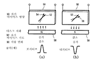
일 예로서 MR 소자의 바이어스 자계가 도 8과 같이 부여되고 있는 경우를 살펴본다. 도 8에 도시한 MR 소자(50)에는 바이어스 자계가 실선으로 도시한 화살표(52) 방향, 즉 디스크(58)로부터 위쪽으로 약 45도의 방향으로 미리 부여되어 있다고 하고, 도 8의 (a)와 같이 디스크(58)의 자계가 N이면, MR 소자의 자화 방향은 점선 화살표(54)와 같이 위쪽으로 변화하게 된다. 이 때의 MR 소자의 저항은 감소하는 방향으로 변화한다. 이 때 얻어지는 출력 신호를 포지티브로 한다. 반대로, 도 8의 (b)와 같이 디스크(58)의 자계가 S이면 MR 소자의 자화 방향은 도 8의 (b)의 점선 화살표(56) 방향의 디스크쪽으로 변화한다. 이 때의 저항 변화는 도 8의 (a)의 경우와 반대로 저항 증가가 되어, 출력이 네거티브로 된다.As an example, a case in which the bias magnetic field of the MR element is provided as shown in FIG. 8 will be described. It is assumed that the
이 경우, 서멀 애스페리티의 영향은 MR 소자의 저항 증가이므로, 네거티브 신호를 출력하게 된다. 따라서, 이러한 바이어스 자계를 갖고, 포지티브, 네거티브를 위에서 기술한 바와 같이 출력하는 구성의 경우, 서보 패드의 최종 출력 신호의 극성이 네거티브가 되고, 그레이 코드의 스타트 비트의 극성이 포지티브가 되도록 서보 신호의 기록을 행하면, 서멀 애스페리티에 의한 네거티브 신호를 잘못 판독하는 일이 없다.In this case, since the influence of the thermal aperity is an increase in the resistance of the MR element, a negative signal is output. Therefore, in the case of such a configuration having such a bias magnetic field and outputting positive and negative as described above, the polarity of the servo output signal becomes negative and the polarity of the start bit of gray code becomes positive. When recording is performed, the negative signal due to the thermal aperity is not misread.
MR 소자의 바이어스 자계 방향이 도 8과는 반대로 디스크 방향을 향하여, 즉 아래쪽을 향하여 약 45도 경사진 구성이면, 도 8에서 설명한 바와는 반대의 극성 신호가 얻어지게 되므로, 반대의 자화 패턴으로 서보 패드의 신호와 그레이 코드의 스타트 비트를 구성하는 것이 필요해진다. 어느 경우에도, 서멀 애스페리티에서 발생하는 신호는 MR 소자의 저항 증가에 의해 발생하는 신호이며, 이 신호가 네거티브인 구성으로 된 시스템일 때는 그레이 코드의 스타트 비트 신호는 포지티브 극성의 신호를 발생하는 자화 패턴으로 하고, MR 소자의 저항 증가에 의해 발생하는 신호가 포지티브인 구성을 갖는 시스템인 경우는 그레이 코드의 스타트 비트가 네거티브 극성의 신호를 발생하는 자화 패턴이 되도록 서보 패턴의 기록을 실행하면 좋다.If the bias magnetic field direction of the MR element is inclined about 45 degrees toward the disc direction, that is, downward, as opposed to FIG. 8, the opposite polarity signal is obtained as described in FIG. It is necessary to configure the signal of the pad and the start bit of the gray code. In either case, the signal generated by the thermal aperity is a signal generated by an increase in the resistance of the MR element. When the system is configured to have a negative configuration, the gray bit start bit signal generates a positive polarity signal. In the case of a system having a configuration in which the magnetization pattern is a signal generated by an increase in the resistance of the MR element, the servo pattern may be written so that the start bit of the gray code becomes a magnetization pattern that generates a signal of negative polarity. .
복수의 MR 소자를 갖고, 이에 상당하는 디스크의 복수의 신호 기록 재생면을 갖는 디스크 장치의 경우에는, 각각의 MR 소자와 이들에 상당하는 각각의 디스크의 서보 영역의 자화 패턴을 상술한 바와 같이 각각 설정하면, 예를 들면 복수의 디스크를 갖는 경우, 또는 디스크 양면을 사용하는 경우 등에서도 모든 면에서, 스타트 비트의 판독 오류를 방지할 수 있게 된다.In the case of a disk apparatus having a plurality of MR elements and having a plurality of signal recording and reproducing surfaces of the disk corresponding thereto, the magnetization patterns of the respective MR elements and servo regions of the respective disks corresponding thereto are respectively described as described above. When set, for example, when there are a plurality of disks or when both surfaces of the disk are used, the read error of the start bit can be prevented in all aspects.
본 발명에 의하면, 디스크에 대한 헤드의 위치 정보인 서보 영역의 이레이즈 영역에 출현하는 서멀 애스페리티를 그레이 코드의 스타트 비트로서 잘못 판독하는 일이 없어, 서보 영역에서의 서멀 애스페리티 대책으로서 양호한 구성이 된다.According to the present invention, the thermal asperity appearing in the erase area of the servo area, which is the positional information of the head with respect to the disc, is not erroneously read as the start bit of the gray code, and as a countermeasure for the thermal aperity in the servo area. A good configuration is obtained.
Claims (4)
Applications Claiming Priority (1)
| Application Number | Priority Date | Filing Date | Title |
|---|---|---|---|
| PCT/JP1995/001158 WO1996042081A1 (en) | 1995-06-08 | 1995-06-08 | Disk apparatus and servo-pattern write system |
Publications (2)
| Publication Number | Publication Date |
|---|---|
| KR19990021867A KR19990021867A (en) | 1999-03-25 |
| KR100259446B1 true KR100259446B1 (en) | 2000-06-15 |
Family
ID=14125996
Family Applications (1)
| Application Number | Title | Priority Date | Filing Date |
|---|---|---|---|
| KR1019970708341A KR100259446B1 (en) | 1995-06-08 | 1995-06-08 | Disk apparatus and servo-pattern write system |
Country Status (5)
| Country | Link |
|---|---|
| US (1) | US6034829A (en) |
| EP (1) | EP0831462A1 (en) |
| JP (1) | JP3089259B2 (en) |
| KR (1) | KR100259446B1 (en) |
| WO (1) | WO1996042081A1 (en) |
Families Citing this family (9)
| Publication number | Priority date | Publication date | Assignee | Title |
|---|---|---|---|---|
| US6611397B1 (en) * | 1998-06-05 | 2003-08-26 | Seagate Technology Llc | Servo burst pattern defect detection |
| US7389374B1 (en) | 2000-05-17 | 2008-06-17 | Marvell International Ltd. | High latency interface between hardware components |
| US7281065B1 (en) | 2000-08-17 | 2007-10-09 | Marvell International Ltd. | Long latency interface protocol |
| US6754015B2 (en) | 2002-03-29 | 2004-06-22 | Seagate Technology Llc | MR heads thermal asperity cancellation |
| JP4102600B2 (en) * | 2002-06-03 | 2008-06-18 | 株式会社日立グローバルストレージテクノロジーズ | Magnetic disk apparatus and signal processing apparatus |
| KR100688556B1 (en) * | 2005-07-12 | 2007-03-02 | 삼성전자주식회사 | Write controlling method of hard disk drive, and hard disk drive and recording medium therefor |
| US7265922B2 (en) * | 2005-10-27 | 2007-09-04 | International Business Machines Corporation | Asperity data storage system, method and medium |
| US7369343B1 (en) | 2006-07-27 | 2008-05-06 | Western Digital Technologies, Inc. | Disk drive correcting track address during a write operation |
| US8773801B2 (en) | 2010-10-21 | 2014-07-08 | HGST Netherlands B.V. | Magnetic-recording head with first thermal fly-height control element and embedded contact sensor element configurable as second thermal fly-height control element |
Family Cites Families (14)
| Publication number | Priority date | Publication date | Assignee | Title |
|---|---|---|---|---|
| US3860965A (en) * | 1973-10-04 | 1975-01-14 | Ibm | Magnetoresistive read head assembly having matched elements for common mode rejection |
| JP2812949B2 (en) * | 1988-03-31 | 1998-10-22 | ソニー株式会社 | Magnetic disk device |
| US4878140A (en) * | 1988-06-21 | 1989-10-31 | Hewlett-Packard Company | Magneto-resistive sensor with opposing currents for reading perpendicularly recorded media |
| US4914398A (en) * | 1988-08-01 | 1990-04-03 | International Business Machines Corporation | Method and circuitry to suppress additive disturbances in data channels containing MR sensors |
| JPH0821213B2 (en) * | 1988-08-05 | 1996-03-04 | 富士通株式会社 | Sector servo information detection method |
| JP2786015B2 (en) * | 1989-12-27 | 1998-08-13 | 茨城日本電気株式会社 | Magnetic disk device |
| US5057785A (en) * | 1990-01-23 | 1991-10-15 | International Business Machines Corporation | Method and circuitry to suppress additive disturbances in data channels |
| US5233482A (en) * | 1991-07-31 | 1993-08-03 | International Business Machines Corporation | Thermal asperity compensation for PRML data detection |
| US5321560A (en) * | 1991-09-25 | 1994-06-14 | Integral Peripherals, Inc. | Embedded servo system for low power disk drives |
| JP3292741B2 (en) * | 1991-10-11 | 2002-06-17 | 松下電器産業株式会社 | Magnetic disk drive |
| JP2953191B2 (en) * | 1992-05-14 | 1999-09-27 | 松下電器産業株式会社 | Magnetic disk drive |
| US5420736A (en) * | 1994-04-15 | 1995-05-30 | International Business Machines Corporation | MR read transducer with thermal noise cancellation |
| JP3048878B2 (en) * | 1995-03-31 | 2000-06-05 | インターナショナル・ビジネス・マシーンズ・コーポレイション | Information recording medium, head position identification method, and information recording device |
| JP2974200B2 (en) * | 1995-07-26 | 1999-11-08 | インターナショナル・ビジネス・マシーンズ・コーポレイション | Servo information identification method for disk device |
-
1995
- 1995-06-08 EP EP95921143A patent/EP0831462A1/en not_active Withdrawn
- 1995-06-08 JP JP09502882A patent/JP3089259B2/en not_active Expired - Fee Related
- 1995-06-08 US US08/973,301 patent/US6034829A/en not_active Expired - Lifetime
- 1995-06-08 KR KR1019970708341A patent/KR100259446B1/en not_active IP Right Cessation
- 1995-06-08 WO PCT/JP1995/001158 patent/WO1996042081A1/en active IP Right Grant
Also Published As
| Publication number | Publication date |
|---|---|
| EP0831462A1 (en) | 1998-03-25 |
| KR19990021867A (en) | 1999-03-25 |
| WO1996042081A1 (en) | 1996-12-27 |
| JP3089259B2 (en) | 2000-09-18 |
| EP0831462A4 (en) | 1998-03-25 |
| US6034829A (en) | 2000-03-07 |
Similar Documents
| Publication | Publication Date | Title |
|---|---|---|
| US5825578A (en) | Method and apparatus for compensating track position due to written-in runout error in a disc drive | |
| JPH0430111B2 (en) | ||
| KR970067149A (en) | Optical disc recording medium and optical disc drive device | |
| JPH04241268A (en) | Magnetic disk and magnetic disk device | |
| US6765748B2 (en) | Method of interleaving servo information fields for track following and seeking and a recording medium including interleaved servo information fields | |
| KR100259446B1 (en) | Disk apparatus and servo-pattern write system | |
| US6014282A (en) | Magnetic disk apparatus and method of detecting head fault | |
| JP3039855B2 (en) | Disk drive device and write control method for disk drive device | |
| JP3721255B2 (en) | Magnetic information storage device | |
| US5815332A (en) | Recording medium having improved servo compensation and method for same | |
| KR100245141B1 (en) | Disk drive apparatus and servo information identification method | |
| JP3078224B2 (en) | Magnetic disk drive and head positioning control system applied thereto | |
| JP3099133B2 (en) | Method of forming servo data | |
| JP3910736B2 (en) | Disk storage device and servo sector address error detection method in the same device | |
| KR950000554B1 (en) | Magnetic recording and reproducing apparatus | |
| KR100273820B1 (en) | Magnetic recording medium and its magnetic recording and reproducing apparatus | |
| JPH05174516A (en) | Recording medium and magnetic disc unit employing recording medium | |
| US6055121A (en) | Optimizing track address detection in a disc drive | |
| JPS63136357A (en) | Rotating speed control method | |
| JP3339528B2 (en) | Magnetic recording / reproducing device | |
| JPH04302864A (en) | Method for recording servo data of magnetic recording and reproducing device | |
| KR100392615B1 (en) | Method for controlling head position of hard disk drive having three bursts | |
| JPH09161250A (en) | Information recording medium, information recording and reproducing method thereof | |
| KR0175259B1 (en) | Method for detecting head position of disc driving record device using disk media with three bursts | |
| JP2947337B2 (en) | Servo system for magnetic disk drive |
Legal Events
| Date | Code | Title | Description |
|---|---|---|---|
| A201 | Request for examination | ||
| E701 | Decision to grant or registration of patent right | ||
| GRNT | Written decision to grant | ||
| FPAY | Annual fee payment |
Payment date: 20080318 Year of fee payment: 9 |
|
| LAPS | Lapse due to unpaid annual fee |