KR100242558B1 - Head lamp - Google Patents
Head lamp Download PDFInfo
- Publication number
- KR100242558B1 KR100242558B1 KR1019970040561A KR19970040561A KR100242558B1 KR 100242558 B1 KR100242558 B1 KR 100242558B1 KR 1019970040561 A KR1019970040561 A KR 1019970040561A KR 19970040561 A KR19970040561 A KR 19970040561A KR 100242558 B1 KR100242558 B1 KR 100242558B1
- Authority
- KR
- South Korea
- Prior art keywords
- reflector
- reflecting plate
- bulb
- plate
- lens
- Prior art date
Links
Images


Classifications
-
- F—MECHANICAL ENGINEERING; LIGHTING; HEATING; WEAPONS; BLASTING
- F21—LIGHTING
- F21S—NON-PORTABLE LIGHTING DEVICES; SYSTEMS THEREOF; VEHICLE LIGHTING DEVICES SPECIALLY ADAPTED FOR VEHICLE EXTERIORS
- F21S41/00—Illuminating devices specially adapted for vehicle exteriors, e.g. headlamps
- F21S41/30—Illuminating devices specially adapted for vehicle exteriors, e.g. headlamps characterised by reflectors
- F21S41/32—Optical layout thereof
- F21S41/36—Combinations of two or more separate reflectors
-
- B—PERFORMING OPERATIONS; TRANSPORTING
- B60—VEHICLES IN GENERAL
- B60Q—ARRANGEMENT OF SIGNALLING OR LIGHTING DEVICES, THE MOUNTING OR SUPPORTING THEREOF OR CIRCUITS THEREFOR, FOR VEHICLES IN GENERAL
- B60Q1/00—Arrangement of optical signalling or lighting devices, the mounting or supporting thereof or circuits therefor
- B60Q1/02—Arrangement of optical signalling or lighting devices, the mounting or supporting thereof or circuits therefor the devices being primarily intended to illuminate the way ahead or to illuminate other areas of way or environments
- B60Q1/04—Arrangement of optical signalling or lighting devices, the mounting or supporting thereof or circuits therefor the devices being primarily intended to illuminate the way ahead or to illuminate other areas of way or environments the devices being headlights
- B60Q1/0408—Arrangement of optical signalling or lighting devices, the mounting or supporting thereof or circuits therefor the devices being primarily intended to illuminate the way ahead or to illuminate other areas of way or environments the devices being headlights built into the vehicle body, e.g. details concerning the mounting of the headlamps on the vehicle body
-
- F—MECHANICAL ENGINEERING; LIGHTING; HEATING; WEAPONS; BLASTING
- F21—LIGHTING
- F21S—NON-PORTABLE LIGHTING DEVICES; SYSTEMS THEREOF; VEHICLE LIGHTING DEVICES SPECIALLY ADAPTED FOR VEHICLE EXTERIORS
- F21S41/00—Illuminating devices specially adapted for vehicle exteriors, e.g. headlamps
- F21S41/30—Illuminating devices specially adapted for vehicle exteriors, e.g. headlamps characterised by reflectors
- F21S41/32—Optical layout thereof
- F21S41/321—Optical layout thereof the reflector being a surface of revolution or a planar surface, e.g. truncated
-
- F—MECHANICAL ENGINEERING; LIGHTING; HEATING; WEAPONS; BLASTING
- F21—LIGHTING
- F21W—INDEXING SCHEME ASSOCIATED WITH SUBCLASSES F21K, F21L, F21S and F21V, RELATING TO USES OR APPLICATIONS OF LIGHTING DEVICES OR SYSTEMS
- F21W2102/00—Exterior vehicle lighting devices for illuminating purposes
-
- F—MECHANICAL ENGINEERING; LIGHTING; HEATING; WEAPONS; BLASTING
- F21—LIGHTING
- F21W—INDEXING SCHEME ASSOCIATED WITH SUBCLASSES F21K, F21L, F21S and F21V, RELATING TO USES OR APPLICATIONS OF LIGHTING DEVICES OR SYSTEMS
- F21W2107/00—Use or application of lighting devices on or in particular types of vehicles
- F21W2107/10—Use or application of lighting devices on or in particular types of vehicles for land vehicles
Landscapes
- Engineering & Computer Science (AREA)
- General Engineering & Computer Science (AREA)
- Mechanical Engineering (AREA)
- Non-Portable Lighting Devices Or Systems Thereof (AREA)
Abstract
본 발명은 헤드램프의 벌브에서 발산된 빔을 반사하는 반사판을 상하로 나누어 상측은 파라볼라(parabola)형 반사판으로, 하측은 이립티컬(elliptical)형 반사판으로 형성하여 배광성능을 향상시킬 수 있도록 하는 것으로, 이는 반사판이 차량에 고정된 하우징(1) 내에 내입되고, 빔을 조사하도록 된 필라멘트를 갖는 벌브(3)가 반사판의 후방으로부터 삽입되어 전방을 향하도록 설치되며, 이격관(5)에 의해 소정거리 이격된 비구면 렌즈(8)가 이 반사판의 전면에 배치되는 한편, 반사판의 빔을 차단하는 플레이트(6)가 이격관(5)의 내측 하단에 입설되며, 렌즈(7)와 더스트 커버(4)가 하우징(1)의 전후방에 각각 결합된 헤드램프에 있어서, 이 반사판을 상하로 분할하되, 상측 반사판은 바이폴라형 반사판(2a)으로 구성되고 하측 반사판은 이립티컬형 반사판(2b)으로 구성된 헤드램프의 배광장치에 관한 것이다.The present invention is to divide the reflector reflecting the beam emitted from the bulb of the headlamp up and down to form a parabola reflector, the upper side to form an elliptical reflector to improve the light distribution performance. , Which is installed in the housing 1 in which the reflector is fixed to the vehicle, and is installed such that a bulb 3 having a filament adapted to irradiate a beam is inserted from the rear of the reflector and faces forward, and is defined by the spacer 5. A distance-separated aspherical lens 8 is disposed in front of the reflecting plate, while a plate 6 blocking the beam of the reflecting plate is placed in the inner lower end of the separating tube 5, and the lens 7 and the dust cover 4 are disposed. In the headlamps in which the heads are respectively coupled to the front and rear of the housing 1, the reflecting plate is divided up and down, wherein the upper reflecting plate is composed of a bipolar reflecting plate 2a and the lower reflecting plate is formed of an elliptically reflecting plate 2b. It relates to a light distribution device of the formed head lamp.
[색인어][Index]
헤드램프, 반사판, 빔, 배광장치, 파라볼라, 이립티컬Headlamps, reflectors, beams, light distribution, parabola, and isometric
Description
본 발명은 헤드램프의 배광장치에 관한 것으로서, 더욱 상세하게는 헤드램프의 벌브에서 발산된 빔을 반사하는 반사판을 상하로 나누어, 상측은 파라볼라형 반사판으로 하측은 이립티컬형 반사판으로 형성하여 배광성능을 향상시킬 수 있도록 하는 헤드램프의 배광장치에 관한 것이다.The present invention relates to a light distribution device for a headlamp, and more particularly, a reflector reflecting a beam emitted from a bulb of a headlamp is divided into upper and lower sides, and an upper side is formed of a parabolic reflector and a lower side is formed of an inverted reflector. It relates to a light distribution device of a head lamp to improve the.
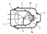
종래의 헤드램프는 도 1에 도시한 것처럼, 차량에 고정 설치되는 하우징(1)내에는 이립티컬형 반사판(2a:elliptical type reflector)이 내입되고, 이 반사판(2a)의 후방에는 전방으로 빔을 조사할 수 있도록 이루어진 필라멘트를 갖는 벌브(3)이 설치되고 이 반사판(2a)의 전면에는 이격관(5)에 의해 소정거리 이격된 비구면 렌즈(8)가 배치되는 한편, 이 이격관(5)의 내측 하단에는 플레이트(6)가 입설되며, 하우징(1)의 전후방에는 렌즈(7)와 더스트 커버(4;dust cover)가 각각 결합되어있다.In the conventional head lamp, as shown in FIG. 1, an elliptical type reflector (2a) is embedded in the housing 1 fixedly installed in a vehicle, and a beam is forwarded to the rear of the
이와 같이 구성된 헤드램프의 동작을 설명한다.The operation of the headlamp configured as described above will be described.
다기능 레버의 조작으로 벌브(3)가 점등하게 되면, 벌브(3)에서 발산된 빔은 방사형으로 발산되어 반사판(2a)에 닿게 되고 이어서 이립티컬형 반사판(2a)에 의해 도 1에서와 같이 반사되게 된다.When the
그리고 반사판(2)에 의하여 반사되는 빔은 비구면 렌즈(8)를 통과하면서 수평방향의 빔으로 변환되어 렌즈(7)를 통해 외부로 조사되게 된다.The beam reflected by the reflector 2 is converted into a horizontal beam while passing through the
특히, 이격관(5)의 내측 하단에 입설된 플레이트(6)가 반사판(2a)에 의해 반사된 빔의 일부가 차단됨으로서 반사되는 빛이 전부 반사되지 못하고 사장이 되는 경우가 초래되어 반사효율이 저조한 문제가 있었다.In particular, since the part of the beam reflected by the
따라서, 반사판에 의해 반사되는 빔 중 일부가 플레이트의 이면에 닿으면서 소멸되어 벌브의 빔이 손실되는 결점을 가진다.Therefore, some of the beams reflected by the reflector plate disappear as they reach the back surface of the plate, so that the beam of the bulb is lost.
즉, 벌브에서 발산되는 빔을 모두 전방으로 조사하지 못하고 일부를 손실하게 되는 것이다.That is, all the beams emitted from the bulb cannot be irradiated forward and some of them are lost.
이에 본 발명은 상기한 바와같이 손실되는 빔을 줄이기 위하여 안출된 것으로, 제3도, 4도에 있는 이립티컬형 반사판과 바라폴라형 반사판의 반사원리를 이용하여 배광성능을 향상시키기 위하여 반사판을 분할하여 벌브에서 발산되는 전방으로 조사되는 조사량을 증대시키는 헤드램프의 배광장치를 제공하고져 하는데 그 목적이 있다.Accordingly, the present invention is designed to reduce the loss of the beam as described above, by dividing the reflector to improve the light distribution performance by using the reflection principle of the elliptically reflector and the barola polar reflector in FIGS. It is an object of the present invention to provide a light distribution device for a head lamp that increases the amount of radiation irradiated forward from the bulb.
제1도는 종래 헤드램프를 도시한 단면도1 is a cross-sectional view showing a conventional head lamp
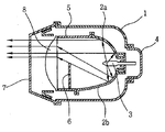
제2도는 본 발명에 따른 헤드램프를 도시한 단면도2 is a cross-sectional view showing a headlamp according to the present invention.
제3도는 파라볼라형 반사판의 반사원리를 설명하기 위한 개략도3 is a schematic view for explaining the reflection principle of the parabolic reflector
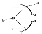
제4도는 이립티컬형 반사판의 반사원리를 설명하기위한 개략도4 is a schematic diagram for explaining the principle of reflection of an isometric reflective plate
* 도면의 주요부분에 대한 부호의 설명* Explanation of symbols for main parts of the drawings
1 : 하우징 2a, 10 : 파라볼라 반사판1
2b, 11 : 이립티컬 반사판 3 : 벌브2b, 11: erectile reflector 3: bulb
4 : 더스트 카버 5 : 이격관4: dust carver 5: spacing
6 : 플레이트 7 : 렌즈6: plate 7: lens
8 : 비구면 렌즈 9a, 9b : 광원8:
9a, 9b : 광원 10 : 파라볼라형 반사판9a, 9b: light source 10: parabolic reflector
상기한 바와같은 목적을 달성하기 위한 본 발명은 반사판이 차량에 고정된 하우징 내에 내입되고, 빔을 조사하도록 된 필라멘트를 갖는 벌브가 반사판의 후방으로부터 삽입되어 전방을 향하도록 설치되며 이격관에 의해 소정거리 이격된 비구면 렌즈가 이 반사판의 전면에 배치되는 한편, 반사판의 빔을 차단하는 플레이트가 이격관 내측 하단에 입설되며 렌즈와 더스트 카버가 하우징의 전후방에 각각 결합된 헤드램프에 있어서, 이 반사판을 상하로 분할하되, 상측 반사판은 바이폴라형 반사판으로 구성되고, 하측 반사판은 이립티컬형 반사판으로 구성되어짐을 특징으로 한다.The present invention for achieving the object as described above is installed so that the reflector is embedded in the housing fixed to the vehicle, the bulb having a filament to be irradiated beam is inserted from the rear of the reflector to face the front and is predetermined by the spacer tube In a headlamp where a distance-aspherical lens is disposed in front of the reflecting plate, a plate blocking the beam of the reflecting plate is placed at the lower end of the separating tube, and the lens and the dust carver are respectively coupled to the front and rear of the housing. The upper and lower reflectors are divided into bipolar reflectors, and the lower reflectors are composed of an ergonomic reflector.
이하 본 발명의 일 실시예에 따른 구성을 예시도면과 함께 보다 상세히 설명하면 다음과 같다.Hereinafter, the configuration according to an embodiment of the present invention in more detail with an exemplary drawing as follows.
도 2는 본 발명에 따른 헤드램프를 도시한 단면도이고, 도 3은 파라볼라형 반사판의 반사원리를 설명하기위한 개략도이다.2 is a cross-sectional view showing a head lamp according to the present invention, Figure 3 is a schematic diagram for explaining the principle of reflection of the parabolic reflector.
본 발명은 도 2에 도시한 것처럼, 차량에 고정 설치되는 하우징(1) 내에는 상측과 하측으로 분할되어 파라볼라형인 상부 반사판(2a)과 이립티컬형 하부 반사판(2b)으로 구성된 반사판이 내입되고, 이 반사판(2a)(2b)의 후방에는 전방으로 빔을 조사할 수 있도록 이루어진 필라멘트를 갖는 벌브(3)이 설치되며, 이 반사판(2a)(2b)의 전면에는 이격관(5)에 의해 소정거리 이격된 비구면 렌즈(8)가 배치되는 한편, 이 이격관(5)의 내측하단에는 플레이트(6)가 입설되며, 하우징(1)의 전후방에는 렌즈(7)와 더스트 커버(4)가 각각 결합되어있다.In the present invention, as shown in Fig. 2, in the housing 1 fixedly installed in a vehicle, a reflecting plate composed of an upper reflecting
이와 같이 구성된 헤드램프의 동작을 설명한다.The operation of the headlamp configured as described above will be described.
본 발명의 동작을 설명하기 이전에 파라볼라형 반사판과 이립티컬형 반사판에 대해 설명하면 다음과 같다.Before describing the operation of the present invention will be described with respect to the parabolic reflector and the ellipsisular reflector.
먼저 파라볼라형 반사판을 채용한 헤드램프는 도3에서와 같이 포물선을 이루어 벌브에서 조사된 각이 파라볼라 형 반사판의 각도로 인하여 직각으로 반사하게 되어 광원(9a)에서 발산된 빔이 파라볼라형 반사판(10)에 반사되면서 수평되게 전방으로 조사되는 특징을 갖는다.First, the head lamp employing the parabolic reflector forms a parabola, as shown in FIG. 3, so that the angle irradiated from the bulb is reflected at right angles due to the angle of the parabola reflector, so that the beam emitted from the
또한 이립티컬형 반사판은 그 자체의 각이 적어 벌브에서 나온 빛이 반사되게 되며 이를 채용항 헤드램프는 도4에 도시한 것처럼 광원(9b)에서 발산된 빔이 이립티컬형 반사판(11)에 반사되면서 소정거리에 있는 지점에서 교차되면서 상하로 조사되는 특징을 갖는다.In addition, the isotropic reflector has a small angle so that light from the bulb is reflected, and the headlamp employing the light reflects the beam emitted from the
이러한 특징으로 갖는 이립티컬형 반사판과 파라볼라형 반사판을 채용한 본 헤드램프에서 다기능 레버의 조작으로 벌브(3)가 점등하게 되면 벌브(3)에서 발산된 빔은 방사형으로 발산되어 상측반사판(2a)과 하측 반사판(2b)에 각각 닿게 되고 이어서 하측 반사판(2b)에 의해 반사된 빔은 종래의 헤드램프에서와 같이 반사되어 비구면 렌즈(8)에 조사된다.When the
또한 상측 반사판(2a)에 의해 반사된 빔은 파라볼라형 반사판의 특성에 의해 벌브(3)에서 발산된 빔이 수평방향으로 반사되어 비구면 렌즈(8)에 조사된다.Further, the beam reflected by the
이렇게 각기 다른 특성을 갖는 상/하부 반사판(2a)(2b)에 의해 반사되는 빔은 비구면 렌즈(8)를 통과하면서 수평방향의 빔으로 변환되어 렌즈(7)를 통해 전면으로 조사되게 된다.The beam reflected by the upper and
따라서 플레이트(6)에 의하여 손실되는 빛이 없이 상측 반사판은 파라볼라형 반사판으로, 하측 반사판은 이립티컬형 반사판으로 조합하여 빛의 손실이 없이 최대의 효율을 가진 헤드램프의 반사판을 가질 수 있다.Accordingly, the upper reflector may be a parabolic reflector without the light lost by the
이상에서와 같이 본 발명은 벌브에서 발산되는 빔을 반사하는 반사판을 파라볼라형 반사판과 이립티컬형 반사판으로 상하분할하여 설치함으로써, 벌브에서 발산되는 빔을 손실없이 전방으로 조사할 수 있는 것이다.As described above, according to the present invention, the reflecting plate reflecting the beam emitted from the bulb is divided into upper and lower parts by using a parabolic reflector and an elliptically reflecting plate so that the beam emitted from the bulb can be irradiated forward without loss.
즉, 빔의 손실을 줄여 헤드램프의 배광성능을 향상시킬 수 있음은 물론이고, 더 나아가서는 헤드램프의 크기를 줄일 수 있는 효과가 있다.That is, the light loss performance of the head lamp can be improved by reducing beam loss, and further, the size of the head lamp can be reduced.
Claims (1)
Priority Applications (1)
| Application Number | Priority Date | Filing Date | Title |
|---|---|---|---|
| KR1019970040561A KR100242558B1 (en) | 1997-08-25 | 1997-08-25 | Head lamp |
Applications Claiming Priority (1)
| Application Number | Priority Date | Filing Date | Title |
|---|---|---|---|
| KR1019970040561A KR100242558B1 (en) | 1997-08-25 | 1997-08-25 | Head lamp |
Publications (2)
| Publication Number | Publication Date |
|---|---|
| KR19990017582A KR19990017582A (en) | 1999-03-15 |
| KR100242558B1 true KR100242558B1 (en) | 2000-03-02 |
Family
ID=19518380
Family Applications (1)
| Application Number | Title | Priority Date | Filing Date |
|---|---|---|---|
| KR1019970040561A KR100242558B1 (en) | 1997-08-25 | 1997-08-25 | Head lamp |
Country Status (1)
| Country | Link |
|---|---|
| KR (1) | KR100242558B1 (en) |
Cited By (1)
| Publication number | Priority date | Publication date | Assignee | Title |
|---|---|---|---|---|
| KR101131317B1 (en) * | 2009-07-14 | 2012-04-04 | 주식회사 휠코리아 | A lighting apparatus using reflection and refraction |
Families Citing this family (1)
| Publication number | Priority date | Publication date | Assignee | Title |
|---|---|---|---|---|
| JP2006210169A (en) * | 2005-01-28 | 2006-08-10 | Stanley Electric Co Ltd | Vehicular headlight |
-
1997
- 1997-08-25 KR KR1019970040561A patent/KR100242558B1/en not_active IP Right Cessation
Cited By (1)
| Publication number | Priority date | Publication date | Assignee | Title |
|---|---|---|---|---|
| KR101131317B1 (en) * | 2009-07-14 | 2012-04-04 | 주식회사 휠코리아 | A lighting apparatus using reflection and refraction |
Also Published As
| Publication number | Publication date |
|---|---|
| KR19990017582A (en) | 1999-03-15 |
Similar Documents
| Publication | Publication Date | Title |
|---|---|---|
| US7748880B2 (en) | Vehicle lamp with overhead sign illumination | |
| EP2525141B1 (en) | Vehicle headlamp | |
| EP2182272B1 (en) | Vehicular lamp unit and vehicular lamp | |
| US6910792B2 (en) | Projection-type vehicular headlamp having improved lateral illumination | |
| TWI624621B (en) | Headlight device | |
| JP4181691B2 (en) | Vehicle lighting | |
| JP2006216551A (en) | Vertical type headlight for automobile | |
| WO2021093233A1 (en) | Reflection-type headlamp module, headlamp module, headlamp and vehicle | |
| US7121704B2 (en) | Vehicle headlamp | |
| EP4365484A1 (en) | Adb high and low beam integrated vehicle lamp illumination module and vehicle lamp | |
| JP5326821B2 (en) | Lighting fixtures for vehicles | |
| JP2575236Y2 (en) | Projector lamp | |
| CN1952470A (en) | Projection type optical system structure | |
| CN105351860A (en) | Light collecting device and headlamp provided with light splitting structure | |
| JP2023553723A (en) | A light-emitting module with a parasitic ray blocker that reflects the irradiated surface of the condenser | |
| JP2001351408A (en) | Lighting fixture for vehicle | |
| CN210662689U (en) | Reflection-type headlamp module, headlamp and vehicle | |
| KR100242558B1 (en) | Head lamp | |
| JP2017208208A (en) | Lamp | |
| CN213362317U (en) | Lighting lamp | |
| CN205208372U (en) | Light collection device device and head -light with beam -splitting structure | |
| JP2558793Y2 (en) | Vehicle headlights | |
| CN112503478A (en) | Lighting lamp | |
| JPH06314503A (en) | Projector-type head lamp | |
| CN216047401U (en) | Car light module, motor vehicle head-light and motor vehicle |
Legal Events
| Date | Code | Title | Description |
|---|---|---|---|
| A201 | Request for examination | ||
| E902 | Notification of reason for refusal | ||
| E701 | Decision to grant or registration of patent right | ||
| GRNT | Written decision to grant | ||
| FPAY | Annual fee payment |
Payment date: 20020723 Year of fee payment: 6 |
|
| LAPS | Lapse due to unpaid annual fee |