KR0157611B1 - Total focus 3-d camera and 3-d image structure - Google Patents
Total focus 3-d camera and 3-d image structure Download PDFInfo
- Publication number
- KR0157611B1 KR0157611B1 KR1019890001183A KR890001183A KR0157611B1 KR 0157611 B1 KR0157611 B1 KR 0157611B1 KR 1019890001183 A KR1019890001183 A KR 1019890001183A KR 890001183 A KR890001183 A KR 890001183A KR 0157611 B1 KR0157611 B1 KR 0157611B1
- Authority
- KR
- South Korea
- Prior art keywords
- image
- lens
- dimensional
- lenses
- bands
- Prior art date
Links
Images


Classifications
-
- G—PHYSICS
- G03—PHOTOGRAPHY; CINEMATOGRAPHY; ANALOGOUS TECHNIQUES USING WAVES OTHER THAN OPTICAL WAVES; ELECTROGRAPHY; HOLOGRAPHY
- G03B—APPARATUS OR ARRANGEMENTS FOR TAKING PHOTOGRAPHS OR FOR PROJECTING OR VIEWING THEM; APPARATUS OR ARRANGEMENTS EMPLOYING ANALOGOUS TECHNIQUES USING WAVES OTHER THAN OPTICAL WAVES; ACCESSORIES THEREFOR
- G03B35/00—Stereoscopic photography
- G03B35/08—Stereoscopic photography by simultaneous recording
- G03B35/12—Stereoscopic photography by simultaneous recording involving recording of different viewpoint images in different colours on a colour film
-
- G—PHYSICS
- G03—PHOTOGRAPHY; CINEMATOGRAPHY; ANALOGOUS TECHNIQUES USING WAVES OTHER THAN OPTICAL WAVES; ELECTROGRAPHY; HOLOGRAPHY
- G03B—APPARATUS OR ARRANGEMENTS FOR TAKING PHOTOGRAPHS OR FOR PROJECTING OR VIEWING THEM; APPARATUS OR ARRANGEMENTS EMPLOYING ANALOGOUS TECHNIQUES USING WAVES OTHER THAN OPTICAL WAVES; ACCESSORIES THEREFOR
- G03B35/00—Stereoscopic photography
- G03B35/08—Stereoscopic photography by simultaneous recording
- G03B35/10—Stereoscopic photography by simultaneous recording having single camera with stereoscopic-base-defining system
Landscapes
- Physics & Mathematics (AREA)
- General Physics & Mathematics (AREA)
- Stereoscopic And Panoramic Photography (AREA)
Abstract
내용없음.None.
Description
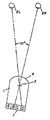
제1도는 렌즈 스크린 중앙의 양 옆에 대칭적으로 배열된 4개의 이미지 밴드를 갖는 3차원 사진을 보는 통상의 방법을 나타내는 개략도.1 is a schematic diagram illustrating a conventional method of viewing a three-dimensional photograph having four image bands symmetrically arranged on both sides of the center of the lens screen.
제2도는 시계각이 렌즈 스크린의 오른쪽으로 비스듬히 기운 제1도의 렌즈를 나타내는 개략도.FIG. 2 is a schematic diagram showing the lens of FIG. 1 in which the clock angle tilts obliquely to the right side of the lens screen. FIG.
제3도는 시계각이 렌즈 스크린의 왼쪽으로 비스듬히 기운 제1도의 렌즈를 나타내는 개략도.3 is a schematic representation of the lens of FIG. 1 with a clockwise angle tilted obliquely to the left of the lens screen.
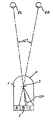
제4도는 8.5° 내지 11°의 시계각을 차지하는 렌즈의 3개의 이미지 밴드를 갖는 3차원 사진을 바라보는 개략도.4 is a schematic view of a three-dimensional photograph with three image bands of a lens occupying a viewing angle of 8.5 ° to 11 °.
제5도는 시계각이 렌즈 스크린의 왼쪽으로 비스듬히 기운 제4도의 렌즈를 나타내는 개략도.FIG. 5 is a schematic diagram showing the lens of FIG. 4 with the clock angle tilted obliquely to the left of the lens screen. FIG.
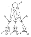
제6도는 3렌즈 카메라로 입체사진을 찍는 과정을 도시한 개략도.6 is a schematic diagram showing a process of taking a three-dimensional picture with a three-lens camera.
제7도는 3렌즈 카메라에 찍힌 입체사진을 렌즈 사진 재료상에 구성하는 과정을 나타내는 도면.7 is a view showing a process of constructing a three-dimensional photograph taken by a three-lens camera on a lens photographic material.
제8도는 각 렌즈당 3개의 이미지 밴드를 갖는 일부 렌즈를 나타내는 입체 렌즈 사진 재료의 개략도, 및8 is a schematic diagram of a stereoscopic lens photographic material showing some lenses having three image bands for each lens, and
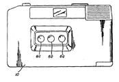
제9도는 본 발명의 3렌즈 카메라의 정면도이다.9 is a front view of the three-lens camera of the present invention.
* 도면의 주요부분에 대한 부호의 설명* Explanation of symbols for main parts of the drawings
I : 렌즈 2L,2R : 사람의 눈I:
3 : 초점 4 : 렌즈스크린3: Focus 4: Lens Screen
8 : 사진 9 : 감광성물질8: Photo 9: Photosensitive material
A,B,C,D : 이미지 밴드 6a,6b,6c : 렌즈A, B, C,
N1,N2,N3 : 음화 L1,L2,L3 : 확대렌즈N1, N2, N3: Negative L1, L2, L3: Magnification
본 발명은 3차원 카메라 및 3차원 이미지 구조에 관한 것으로, 어떠한 시계각으로도 인접한 입체쌍을 볼 수 있고 초점이 완전히 맞는 사진을 제조하며 더 넓은 각으로 사진이 보여질 수 있도록 각각의 이미지 밴드폭이 8.5° 내지 11°되는 3개 이미지 밴드를 갖는 렌즈로 3차원 사진이 제조된다. 이러한 사진을 찍기 위하여 3렌즈 카메라가 제공되고, 각 렌즈내 3개 이미지 밴드는 3렌즈 카메라내 하나의 필름 스트립상에 동시에 포착되고 기록되는 3개 2차원 이미지로부터 제조된다.The present invention relates to a three-dimensional camera and a three-dimensional image structure, each of the image bandwidth to be able to see the adjacent three-dimensional pairs at any angle of view, to produce a picture that is fully in focus, and to view the picture at a wider angle Three-dimensional photographs are produced with lenses having three image bands from 8.5 ° to 11 °. A three lens camera is provided for taking such a picture, and three image bands in each lens are made from three two-dimensional images that are simultaneously captured and recorded on one film strip in the three lens camera.
렌즈의 형태에 있어서, 2차원(2-D) 시계 장면의 복수인 3차원(3-D) 사진술은 수평적으로 위치한 다수의 유리한 지점으로부터 성립되고, 장면의 3차원 복합이미지를 형성하기 위해 연속적인 2차원 이미지는 압축되고 렌즈 스크린의 각 렌즈의 초점면에 인화된다.In the form of a lens, three-dimensional (3-D) photography, which is a plurality of two-dimensional (2-D) field of view scenes, is established from a number of advantageous positions located horizontally, and is continuous to form a three-dimensional composite image of the scene. The two-dimensional image is compressed and printed on the focal plane of each lens of the lens screen.
종래에는 3차원 사진을 합성하기 위하여는 최소한 4개의 2차원적 시계가 사용되었고 다수의 압축된 2차원적 라인폼(lineiform) 이미지 밴드 각각은 렌즈에 있어서 동일한 폭을 차지하였다. 또한 언제나 짝수의 이미지 밴드가 사용되었다. 몇 개의 이미지가 하나의 밴드내에 인화될 수 있다. 이것은 대개 W/N이라고 언급되며 이때 W는 각 렌즈의 폭을 나타내고 N은 전체적인 합성에 사용될 2차원적 이미지 밴드의 수를 나타내며, 입체쌍이 라인폼 이미지 밴드는 렌즈의 렌즈 스크린의 곡면 중앙에 대해 대칭적인 관계로 배열된다.In the past, at least four two-dimensional fields of view were used to synthesize three-dimensional photographs, and each of the plurality of compressed two-dimensional lineiform image bands occupied the same width in the lens. Also, an even number of image bands was always used. Several images can be printed in one band. This is usually referred to as W / N, where W represents the width of each lens and N represents the number of two-dimensional image bands to be used for the overall synthesis, and the stereoscopic pair of lineform image bands is symmetric about the curved center of the lens screen of the lens Are arranged in relation to each other.
어떤 사람이 3차원 사진을 볼 때 인접한 2차원 라인폼 이미지 밴드의 입체쌍을 눈으로 보는 것이 바람직하다. 그러므로 제1도에 설명된 바와 같이 초점이 맞고 또렷한 3차원 이미지를 구성하기 위하여는 2차원 이미지의 쌍 사이의 적당한 시차가 유지되도록 이미지 밴드(A와 B, B와 C, 또는 C와 D)를 보아야만 한다. 시차(prarllax)는 어떤 구성요소가 보여지는 장소 및 구성요소의 위치에 있어서의 상대적인 변화에 기인하는 객체필드(object field)의 구성요소의 위치에 있어서의 외관상의 변화이다. 종래의 3차원 사진을 볼 때 언제나 인접한 2차원 이미지 밴드에 의하여 형성된 입체쌍을 보는 것은 아니다. 종종 사진을 보는 각도 및 거리에 따라 제1도에 나타난 것과 같은 이미지 밴드(A와 C, B와 D, 또는 A와 D)에 의하여 형성된 인접하지 않은 입체쌍을 보게된다. 인접하지 않은 이미지 밴드의 입체쌍을 볼 때 그들사이의 시차가 커서 하나의 견고한 이미지를 형성하기 위해 이미지의 쌍을 융합할 수 없다.When a person looks at a three-dimensional picture, it is desirable to visually see three-dimensional pairs of adjacent two-dimensional lineform image bands. Therefore, in order to construct a focused and clear three-dimensional image as described in FIG. 1, the image bands (A and B, B and C, or C and D) are maintained so that proper parallax is maintained between the pair of two-dimensional images. Must see A parallax is an apparent change in the position of an element in an object field due to a relative change in the place where the element is seen and the position of the element. When looking at a conventional three-dimensional picture, it does not always look at a stereoscopic pair formed by adjacent two-dimensional image bands. Often, depending on the angle and distance at which the photograph is viewed, one sees nonadjacent stereoscopic pairs formed by image bands (A and C, B and D, or A and D) as shown in FIG. When viewing stereoscopic pairs of nonadjacent image bands, the parallax between them is so large that one cannot fuse the pairs of images to form one solid image.
종래의 3차원 사진을 합성하는데 사용되는 최소한의 2차원 시계의 수는 인화물질의 렌즈의 일반적인 시계각이 약20° 내지 30°인 4개이다. 결과적으로 각각의 2차원 이미지 밴드는 7½°보다 작은 각을 차지한다. 15인치의 거리에서 정상적으로 볼 때 렌즈의 약 10°정도의 각으로 보게 된다. 3차원 사진이 정확히 눈 사이의 중앙에 그리고 그들에 수직으로 고정되지 않으면 제1,2,3도에 나타난 것과 같은 이미지 밴드(A와 C, B와 D, 또는 A와 D)에 의하여 형성된 인접하지 않은 입체쌍을 보게 될 것이다.The minimum number of two-dimensional fields of view used to synthesize conventional three-dimensional photographs is four, wherein the general field of view of the lens of the flammable material is about 20 to 30 degrees. As a result, each two-dimensional image band occupies an angle smaller than 7½ °. When viewed normally at a distance of 15 inches, the lens is viewed at an angle of about 10 ° to the lens. If the three-dimensional photographs are not exactly centered between the eyes and perpendicular to them, they are not adjacent to each other formed by image bands (A and C, B and D, or A and D) as shown in Figs. You'll see a solid pair.
Lo외 다수의 미국 특허 제3,895,867호에는 렌즈의 곡선 스크린의 중심을 가로지르는 수직선에 대하여 대칭으로 배열되어 있는 4개 또는 그 이상의 라인폼 이미지 밴드가 있는 3차원 사진을 만드는 방법이 개시되어 있다. Okoshi의 Three-Dimensional Imaging Techniques(1976)의 71-88쪽에 3차원 인화에서의 감광유제에 대한 이미지의 분산에 대해 발표하였다.Lo et al. US Pat. No. 3,895,867 discloses a method of making a three-dimensional photograph with four or more lineform image bands arranged symmetrically about a vertical line across the center of the curved screen of the lens. On pages 71-88 of Okoshi's Three-Dimensional Imaging Techniques (1976), he presented the dispersion of images for photosensitizers in three-dimensional printing.
Lo외 다수의 미국 특허 제3,953,869호, 제4,037,950호, 제4,063,265호, 및 제4,086,585호에도 역시 보고되어 있다.Lo et al. Are also reported in US Pat. Nos. 3,953,869, 4,037,950, 4,063,265, and 4,086,585.
본 발명의 목적은 개선된 품질의 3차원 자동 입체 사진을 제조하는 것이다.It is an object of the present invention to produce an improved quality three-dimensional autostereogram.
본 발명의 목적은 개선된 품질의 3차원 사진보다 흐려지는 경우없이 보다 큰 시계각의 범위와 거리내에서 초점이 항상 맞는 상태로 보이는 사진을 제조하는 것이다.It is an object of the present invention to produce photographs that always appear to be in focus within a larger range of viewing angle and distance without blurring than a three-dimensional photograph of improved quality.
본 발명의 목적은 또한 보다 깊이 있게 보이는 사진을 제조하기 위하여 인접한 입체쌍 사이에서 시차가 증가되는 근접 촬영 물체(close-up object)의 3차원 사진을 제공하는 것이다.It is also an object of the present invention to provide a three-dimensional picture of a close-up object with increased parallax between adjacent three-dimensional pairs in order to produce a picture that looks deeper.
본 발명의 목적은 또한 이러한 목적을 수행할 수 있는 3차원 사진을 제조하기 위하여, 이러한 사진을 찍을 수 있는 능력을 지닌 카메라를 제조하는 것이다.It is also an object of the present invention to produce a camera having the ability to take such a picture, in order to produce a three-dimensional picture which can fulfill this purpose.
카메라에 의해 취해지는 2차원 시계의 수를 3으로 한정하고 라인폼 이미지 밴드 각각의 폭을 적어도 8.5°의 각으로 늘림으로써 위의 목적들을 달성할 수 있다는 것이 알려져 왔다. 2차원 이미지 밴드 각각의 폭이 적어도 렌즈의 8.5°일 경우 이미지(A와 C)를 보지 않게 된다. 이미지 밴드(A와 C)를 보게 되는 경우에는 객체의 사진이 가까운 범위에서 찍히는 일반적인 수요자 사진술에 있어서 두 개의 이미지 사이의 시차가 커지기 때문에 두 개의 이미지가 서로 융합되어질 수 없게 됨에 따라 사진은 초점이 맞지 않게 된다. 눈의 시계각을 조절하기 위하여 이미지 밴드의 폭을 7½°에서 적어도 8.5°로 증가시키므로써, 입체 이미지 밴드의 쌍이 서로 융합되어 하나의 뚜렷한 3차원 이미지를 재정립하도록 적절한 시차가 유지될 때 제4도에서 보이는 바와 같이 이미지 밴드(A와 B 또는 B와 C)만이 입체쌍으로서 보이게 된다. 2차원 이미지 밴드의 수를 3개로 한정한다는 것을 종래의 방법과는 어긋나는 것인데, 과거에는 3차원 사진을 제조하기 위해 많은 수의 2차원 시계가 사용되어야 한다고 생각하였고, 또한 그것이 3차원 효과를 상승시키고 결과적으로 입체쌍 사이에서의 전이를 보다 쉽게 하는 것으로 생각하였다. 또한 사람이 두 개의 눈을 가지고 있다는 사실에 기인하여 렌즈내 이미지 밴드의 수가 짝수이어야 한다고 생각하였다. 본 발명에 따라 제조된 사진에 있어서 원하는 목적을 달성하기 위하여 렌즈가 동일한 간격으로 놓인 3렌즈 카메라가 사용되었다.It has been known that the above objects can be achieved by limiting the number of two-dimensional fields taken by the camera to three and increasing the width of each lineform image band to an angle of at least 8.5 °. If the width of each of the two-dimensional image bands is at least 8.5 ° of the lens, the images A and C are not visible. If you look at the image bands (A and C), the photographs are out of focus as the parallax between the two images becomes larger in general consumer photography where the object's photograph is taken at close range. Will not. By increasing the width of the image band from 7½ ° to at least 8.5 ° to adjust the eye's field of view, the pair of three-dimensional image bands can be fused to each other so that proper parallax is maintained to redefine one distinct three-dimensional image. As can be seen, only the image bands (A and B or B and C) appear as stereoscopic pairs. Limiting the number of two-dimensional image bands to three is inconsistent with conventional methods. In the past, it was thought that a large number of two-dimensional clocks should be used to produce three-dimensional photographs. As a result, it was thought that the transition between three-dimensional pairs was easier. We also thought that the number of image bands in the lens should be even, due to the fact that a person has two eyes. In photographs made according to the invention a three lens camera was used in which the lenses were spaced at equal intervals in order to achieve the desired purpose.
제1도는 3차원 사진의 렌즈(I)내의 입체쌍(B와 C)을 보는 사람을 나타낸다. 렌즈(I)는 4개의 2차원 라인폼 이미지 밴드(A,B,C,D)로 구성된다. 이미지 밴드(A와 B, B와 C, C와 D)는 입체적 이미지 쌍을 구성한다. 이미지 밴드들은 감광성 물질상에 형성된다. 제1도는 관측자의 두 눈(2R,2L) 사이의 중심을 가로지르고 렌즈 스크린(4)의 중심을 통해 통과하는 수직선을 따라 렌즈를 보는 사람의 눈(2R,2L)을 나타낸다. 눈과 눈 사이의 간격은 2½인치 떨어진 것으로 나타나 있는데 이는 사람의 눈 사이의 평균 간격이다. 눈이 사진으로부터 15인치 정도 떨어진 상태일 때 시계각은 약 10도를 차지한다. 사진이 그렇게 고정될 때 관찰자는 10°시계각이 떨어지는 15°각을 차지하는 입체 이미지 쌍(B와 C)을 보게 될 것이다. 시야는 렌즈(I)의 초점면(3)에 초점을 맞출 것이다.1 shows a person viewing stereoscopic pairs B and C in lens I of a three-dimensional photograph. The lens I is composed of four two-dimensional lineform image bands A, B, C, and D. Image bands (A and B, B and C, C and D) constitute a stereoscopic image pair. Image bands are formed on the photosensitive material. FIG. 1 shows the
제2도는 사진이 렌즈 중심과 눈 사이의 중심 사이의 수직선으로부터 약건 벗어난 상태로 고정된 경우에서의 렌즈의 시야를 나타낸다. 이 경우에는 렌즈 스크린(4)의 오른쪽으로 기울어지도록 사진이 고정되었다. 시계각이 10°이고 각 이미지 밴드폭이 7½°인 때, 사진이 그렇게 고정된 경우 인접하지 않은 입체 이미지 쌍(A와 C)을 보게 될 것이다. 이들 이미지 쌍 사이의 시차 때문에 사진은 흐려지고 초점이 완전히 맞지 않게 된다.FIG. 2 shows the field of view of the lens when the picture is fixed in a state slightly off from the vertical line between the center of the lens and the eye. In this case, the picture is fixed so as to tilt to the right of the lens screen 4. When the field of view is 10 ° and each image bandwidth is 7½ °, you will see non-adjacent stereoscopic pairs (A and C) if the picture is so fixed. The parallax between these pairs of images makes the picture blurred and out of focus completely.
제3도는 사진이 렌즈 스크린(4)의 중심과 눈 사이의 중심 사이의 중앙선의 왼쪽으로 기울어졌을 때의 렌즈의 시야를 나타낸다. 제2도의 경우에 각 이미지 밴드가 렌즈의 7½°를 차지하는데 반해서 시계각은 아직도 10°이다. 이 사실로 인해 결과적으로 인접하지 않은 입체 이미지 쌍(B와 D)을 보게 되어 이들 이미지 사이의 시차가 커져서 사진이 흐려보이고 초점이 맞지 않게 된다.3 shows the field of view of the lens when the photograph is tilted to the left of the centerline between the center of the lens screen 4 and the center between the eyes. In the case of FIG. 2, the angle of view is still 10 ° while each image band occupies 7½ ° of the lens. This results in seeing non-adjacent stereoscopic pairs (B and D), which increases the parallax between these images, making the picture blurred and out of focus.
제4도는 3개의 이미지 밴드(A,B,C)만으로 이루어진 렌즈(I)를 나타낸다. 이 경우에 관찰자는 렌즈 스크린(4) 중심과 또한 눈 사이의 중심을 가로지르는 수직선에 따른 각도로 사진을 보게된다. 이런 상태에서 관측자는, 렌즈 스크린이 오른쪽으로 약간 기울어진 경우 이미지 밴드(A와 B)에 의하여 형성된 입체쌍을 보게되고, 렌즈의 스크린이 왼쪽으로 약간 기울어진 경우에는 이미지 밴드(B와 C)에 의하여 형성된 입체쌍을 보게 된다. 이들 이미지 밴드 쌍의 각각은 렌즈의 10°를 차지한다. 시계각이 10°일때는 이미지 밴드의 입접한 쌍만을 보게된다. 결과적으로 렌즈 스크린(4)의 중심을 통과하는 수직선이 왼쪽 눈보다 오른쪽 눈쪽으로 더 가까이 가로지르는 상태로 사진이 고정되는 경우, 제5도에서 보는 것처럼 사진이 눈에 대해서 중심에서 어긋나거나, 또는 기울어질 수 있다. 이런 상태에서 관측자는 입체쌍(B와 C)을 보게 될 것이다. 결과적으로, 시계각이 적어도 8.5°인 3개의 이미지 밴드를 사용한 경우에는 입체쌍이 4개 또는 그 이상의 이미지 밴드의 쌍 사이에서 형성되는 3차원 사진보다는 더 큰 정도로 사진이 기울어지거나 눈의 중심에서 벗어날 수 있다. 각 렌즈내에 단지 3개의 이미지 밴드만이 있기 때문에 렌즈 스크린의 중심으로부터 감광성 물질까지의 수직선이 중앙 이미지 밴드의 거의 중점을 가로지를 수 있도록 이미지 밴드들이 렌즈의 중심에 대하여 맞비기는 구성(offset format)으로 배열되어 있다.4 shows a lens I consisting of only three image bands A, B and C. In this case the observer sees the picture at an angle along a vertical line across the center of the lens screen 4 and also between the eyes. In this state, the observer sees the stereo pair formed by the image bands A and B when the lens screen is tilted slightly to the right, and the image bands B and C when the lens screen is tilted slightly to the left. The three-dimensional pair formed by this is seen. Each of these pairs of image bands occupy 10 ° of the lens. When the field of view is 10 °, you see only the indented pair of image bands. As a result, when the picture is fixed with the vertical line passing through the center of the lens screen 4 closer to the right eye than the left eye, the picture is shifted from the center or tilted with respect to the eye as shown in FIG. Can lose. In this state, the observer will see three-dimensional pairs (B and C). As a result, when three image bands with at least 8.5 ° of viewing angle are used, the image may be tilted or departed from the center of the eye to a greater extent than a three-dimensional photograph in which a stereoscopic pair is formed between a pair of four or more image bands have. Since there are only three image bands in each lens, the image bands are offset in relation to the center of the lens so that the vertical line from the center of the lens screen to the photosensitive material can cross the center of the center image band. Are arranged.
오로지 인접한 입체쌍만을 보도록 보장하기 위해 각 이미지 밴드의 폭은 8.5° 내지 11°이어야 하는 것이 필수적이다. 폭이 8.5°보다 작아지면 눈 사이의 시계각이 10°도 일 때 인접하지 않은 쌍을 볼 수 있게 된다. 만일 렌즈의 전체 시계각이 30°인 경우 각 이미지 밴드의 폭은 11°보다 크기 않아야 한다. 만일 각 이미지 밴드의 폭이 11°보다 커지면 렌즈내에 두 개의 입체쌍을 위치시키는 것이 불가능하게 된다. 만일 15°의 이미지 밴드가 단지 2개 있다면 눈 사이의 시계각이 10°가 될 때 양쪽 눈 각각은 단지 하나의 이미지만을 볼 것이다.It is essential that the width of each image band should be 8.5 ° to 11 ° to ensure that only adjacent pairs of stereograms are seen. If the width is less than 8.5 °, then non-contiguous pairs can be seen when the angle of view between the eyes is 10 °. If the total field of view of the lens is 30 °, the width of each image band shall not be greater than 11 °. If the width of each image band is greater than 11 °, it is impossible to place two stereoscopic pairs in the lens. If there are only two 15 ° image bands, each eye will see only one image when the angle of view between the eyes is 10 °.
배경이 흐림과 뒤틀림 효과 때문에 렌즈 스크린이 30°보다 커지게되면 실용적이지 못하다. 배경의 흐림이란 이미지 밴드에 도달하는 빛이 렌즈 스크린의 가장 자리로 떨어져서 그 결과로 어두운 사진이 제조되는 것을 의미한다. 모든 렌즈에 있어서 빛이 렌즈의 바깥족 가까이 떨어질 때 위의 효과가 특징적으로 나타난다. 40°또는 그 이상의 렌즈 스크린이 10° 또는 그 정도의 이미지 밴드를 더 많이 갖는 것도 가능하다. 위의 경우에는 배경의 흐림과 뒤틀림 효과 때문에 실용적이지 못하다.It is not practical if the lens screen is larger than 30 ° because the background is blurry and distorted. Blur of the background means that light reaching the image band falls to the edge of the lens screen, resulting in a dark picture. For all lenses, the above effect is characteristic when the light falls near the outside of the lens. It is also possible that 40 ° or more lens screens have more image bands of 10 ° or so. In the above case, it is not practical because of the blur and distortion effect of the background.
결과적으로 질이 좋은 3차원 사진을 제조하기 위한 하나의 실제적인 방법은 3개의 이미지 밴드를 갖는 약 30°정도의 렌즈 스크린을 사용하는 것이다. 이미지 밴드의 범위는 약 8½° 내지 11°일 수 있는데 이미지 밴드의 폭은 8½°와 10°사이인 것이 바람직한다. 위의 범위일 때 인접한 이미지만으로 보게 됨에 따라 질이 좋은 사진을 제조하게 된다. 인접하지 않은 이미지를 보게되면 결과적으로 뒤틀림 현상이 나타난다.As a result, one practical way to produce quality three-dimensional photographs is to use a lens screen of about 30 ° with three image bands. The image band can range from about 8½ ° to 11 °, with the width of the image band preferably being between 8½ ° and 10 °. When in the above range, you see only the adjacent images, which produces good quality photos. Viewing nonadjacent images results in distortion.
1렌즈 카메라를 가지고도 본 발명의 입체 사진을 찍을 수 있다. 1렌즈 카메라로 이들 사진을 찍기 위한 한가지 방법은 카메라를 객체에 대하여 3가지 위치로 이동시키고 각 위치에서 사진을 찍는 것이다. 또 다른 방법은 객체를 카메라에 대하여 3가지 다른 위치로 옮기는 것이다. 간편하게 제9도에 나타난 신규의 3렌즈 카메라로 본 발명의 입체 사진을 찍는 것이 바람직하다.The three-dimensional photograph of the present invention can also be taken with a single lens camera. One way to take these pictures with a one-lens camera is to move the camera to three locations with respect to the object and take pictures at each location. Another way is to move the object to three different positions with respect to the camera. It is preferable to take a stereoscopic picture of the present invention simply with the novel three-lens camera shown in FIG.
제6도에 나타난 바와 같이, 객체(5)에 대하여 각각 다른 수평면적 위치에 자리한 3개의 렌즈(6a,6b,6c)를 갖는 입체 카메라로 객체(5)의 사진을 찍는다. 이들은 이미지(7)를 갖는 3개의 음화(N1,N2,N3)를 제조한다. 이들 음화들은 제7도에서 보는 바와 같이 확대렌즈(L1,L2,L3) 또는 이미지(7)를 사진(8)의 렌즈(I)의 감광성 물질(9)로 초점을 맞추는 하나의 렌즈 확대기를 통하여 다시 구성된다. 제7도에서 보는 바와 같이 입체 이미지 밴드(N1i,N2i,N3i)를 형성하기 위해 이미지들은 렌즈 스크린(4)을 통해 초점(3) 및 감광성 물질에 초점이 맞춰진다. 제7도에 나타난 확대 과정에 있어서, 음화(예를 들어 N2)의 이미지는 이미지 밴드 전체 폭을 채우기 위해 여러차례 병행관계(side-by-side relationship)로 적당한 이미지 밴드(A)로 투영될 수 있다. 만일 위 과정이 제8도에 나타난 렌즈(1a)에 있는 이미지 밴드(A)의 경우에 행해졌다면 이미지 밴드(A)에 있는 각각의 이미지는 동일할 것이고, 동일한 2차원적 시계를 가질 것이다.As shown in FIG. 6, the object 5 is photographed with a stereo camera having three
제8도에 나타난 바와 같이 이미지를 렌즈(1a)내의 각 밴드(A)를 가로질러 분산시키기 위해 기존 기술 문헌인 Okoshi의 Thee-Dimensional Imaging Techniques(1976)의 71-88쪽에 기재된 바와 같이 인화의 스캐닝 기법(scanning technique)을 사용하는 것도 또한 가능하다. 각 이미지 밴드에 하나의 이미지가 있기를 원하면, 하나의 이미지가 전 이미지 밴드를 채울 수 있도록 충분한 폭으로 확대기의 틈을 열 수 있다.Scanning of the prints as described on page 71-88 of Okoshi's Thee-Dimensional Imaging Techniques (1976) to disperse the image across each band A in the lens 1a as shown in FIG. It is also possible to use a scanning technique. If you want to have one image in each image band, you can open the gap in the enlarger with enough width so that one image fills the entire image band.
제8도는 앞서 밝혀진 방법에 의하여 채워진 3개의 이미지 밴드를 갖는 각 렌즈로 된 사진을 포함하는 여러개의 렌즈를 나타낸다.8 shows several lenses including photographs of each lens having three image bands filled by the method disclosed above.
제9도에 나타난 카메라(10)는 3개의 렌즈(6a,6b,6c)를 갖는다. 3개의 렌즈는 동일한 수평면상에 배열되고 인접한 렌즈 사이의 거리는 동일한다. 이 카메라는 위의 점 이외에는 종래의 구조로 이루어져 있다.The
각 렌즈가 단지 3개의 이미지 밴드로 구성된 특징을 지닌 본 발명의 렌즈 구조는 종래의 사진에 비해서 보다 넓은 시계각과 거리에서 사진을 볼 수 있다는 점에서 큰 장점을 갖는다. 공통적으로 사용되는 인화물질 렌즈의 일반적인 시계각은 약 30°이다. 이것은 시계각이 점유하는 폭이 8½° 내지 11°사이에서 변화될 수 있지만 각각의 이미지 밴드 폭은 시계각의 약 10°를 차지한다는 것을 의미한다. 이미지 밴드 폭이 10°라는 사실을 기초로 할 때, 약 10°보다 시계각이 작은 경우 10°인 경우보다 사진으로부터 더 멀리서 보게 되고 인접한 이미지 밴드를 볼 수 없게 될 것이다. 반면, 시계각이 약 20°를 초과하지 않는 범위에서 가능한한 짧은 거리에 사진이 있을 수 있다. 20°의 시계각에서 관측 거리는 약 7인치가 된다. 그러나, 이러한 전체 거리 범위에서는 인접한 이미지 밴드를 볼 수 있지만 사진이 적절한 초점을 맞추지 못한다는 것이 지적된다. 구성되는 동안 2차원적인 프레임이 투영되기 때문에 항상 동일한 거리와 위치에서 사진의 렌즈 스크린을 볼 필요는 전혀 없다. 예를 들어, 이미지 밴드(B)내에 다수의 이미지가 있는 경우 제8도에 나타난 렌즈(1a)를 볼 때는 사진이 찍히는 위치와 다른 각도에서 사진이 보여지더라도 이러한 보다 넓은 이미지 밴드내의 어느 특별한 이미지에 초점이 맞춰질 것이다. 제8도의 렌즈(1a)의 이미지 밴드내에 하나의 이미지가 있는 경우, 사진이 통상의 관점위치로부터 약간 기울어진 각도로 관측되더라도 이 이미지를 볼 수 있다. 사진이 기울어지거나 또는 여러 거리에 놓여지더라도 종래의 3차원 사진의 경우와는 달리 사진의 질을 저하시키지 않는다.The lens structure of the present invention, in which each lens consists of only three image bands, has a great advantage in that a photograph can be viewed at a wider angle of view and a distance than a conventional photograph. The common field of view for commonly used flammable lenses is about 30 °. This means that the width occupied by the clock angle can vary between 8½ ° and 11 ° but each image band width occupies about 10 ° of the clock angle. Based on the fact that the image band width is 10 °, if the field of view is less than about 10 °, you will see farther from the picture than if you have 10 ° and you will not be able to see adjacent image bands. On the other hand, there may be photographs as short as possible in a range where the angle of view does not exceed about 20 °. At a 20 ° clock angle, the viewing distance is about 7 inches. However, it is pointed out that in this full range of distances the adjacent image bands can be seen but the photograph does not focus properly. Since the two-dimensional frame is projected during construction, there is no need to always look at the lens screen of the picture at the same distance and location. For example, if there are multiple images in the image band B, when looking at the lens 1a shown in Fig. 8, any particular image in this wider image band may be seen, even if the photograph is viewed at an angle different from the position at which the photograph is taken. Will be in focus. If there is one image in the image band of the lens 1a of FIG. 8, this image can be seen even if the photograph is observed at a slightly inclined angle from the normal viewpoint position. Even when the photograph is inclined or placed at various distances, unlike the conventional 3D photograph, the photograph does not deteriorate.
위에서 언급한 바와 같이 객체를 원하는 상태로 찍을 수 있는 3차원 사진을 제조하기 위하여는 이미지 밴드의 폭은 적어도 8.5°이어야 하고 11°를 너어서는 안된다는 것이 매우 중요하다. 만일 이미지 밴드의 폭이 8.5°보다 작아지면 사진이 기울어질 때 인접하지 않은 입체쌍을 볼 수 있다. 각 렌즈내에 두 개의 입체쌍을 놓는 것은 불가능하기 때문에 양쪽 눈이 모두 동일한 이미지 밴드를 보게 될 때 이미지 밴드는 11°보다 클 수 없다. 원하는 3차원 효과를 얻기 위하여는 적어도 두 개의 입체쌍을 가져야 함이 필수적이다. 종래의 3차원 사진의 경우 사진이 기울어졌을 때 관측자가 종종 인접하지 않은 이미지 밴드를 보기 때문에 질이 좋지 않았다. 이런 이유로 관측자에 의해서 여러 가지 위치로 고정되었을 때, 사진이 초점이 맞지 않거나 또는 뒤틀려지게 된다. 이 문제는 이미지 밴드의 수를 3개로 줄임으로써 해결되었다. 종래에는 이미지 밴드의 수는 항상 짝수이어야 하고 또 적어도 4개의 이미지 밴드가 있어야만 한다고 생각되었다. 또한 이들 이미지 밴드는 폭이 8½°과 11°사이어야 하고 렌즈의 폭은 약30°이어야 한다는 것도 밝혀졌다. 이런 모든 특징들은 질이 우수한 3차원 사진을 제조하는데 필수적이다.As mentioned above, it is very important that the width of the image band should be at least 8.5 ° and not 11 ° in order to produce a three-dimensional photograph in which the object can be taken as desired. If the width of the image band is less than 8.5 °, you can see non-adjacent stereoscopic pairs when the picture is tilted. Since it is impossible to place two solid pairs within each lens, the image band cannot be greater than 11 ° when both eyes see the same image band. In order to achieve the desired three-dimensional effect, it is essential to have at least two solid pairs. In the conventional three-dimensional photographs, the quality is not good because the observer often sees non-adjacent image bands when the photograph is tilted. For this reason, when locked in various positions by the observer, the picture may be out of focus or distorted. This problem was solved by reducing the number of image bands to three. It has conventionally been thought that the number of image bands must always be even and there must be at least four image bands. It has also been found that these image bands should be 8½ ° and 11 ° wide and the lens should be about 30 ° wide. All these features are essential for producing high quality 3D photographs.
Claims (4)
Applications Claiming Priority (2)
| Application Number | Priority Date | Filing Date | Title |
|---|---|---|---|
| US150,977 | 1988-02-01 | ||
| US07/150,977 US4800407A (en) | 1988-02-01 | 1988-02-01 | Total focus 3-D camera and 3-D image structure |
Publications (2)
| Publication Number | Publication Date |
|---|---|
| KR890013517A KR890013517A (en) | 1989-09-23 |
| KR0157611B1 true KR0157611B1 (en) | 1999-03-30 |
Family
ID=22536809
Family Applications (1)
| Application Number | Title | Priority Date | Filing Date |
|---|---|---|---|
| KR1019890001183A KR0157611B1 (en) | 1988-02-01 | 1989-02-01 | Total focus 3-d camera and 3-d image structure |
Country Status (9)
| Country | Link |
|---|---|
| US (1) | US4800407A (en) |
| EP (1) | EP0327303B1 (en) |
| JP (1) | JP2889585B2 (en) |
| KR (1) | KR0157611B1 (en) |
| CN (1) | CN1019232B (en) |
| CA (1) | CA1313790C (en) |
| DE (1) | DE68922915T2 (en) |
| ES (1) | ES2075038T3 (en) |
| HK (1) | HK3496A (en) |
Families Citing this family (22)
| Publication number | Priority date | Publication date | Assignee | Title |
|---|---|---|---|---|
| US5113213A (en) * | 1989-01-13 | 1992-05-12 | Sandor Ellen R | Computer-generated autostereography method and apparatus |
| US4903069A (en) * | 1989-02-24 | 1990-02-20 | Image Technology, Inc. | Automatic three-dimensional photo printer to align the key subject image |
| JPH03255433A (en) * | 1990-03-06 | 1991-11-14 | Toppan Printing Co Ltd | Production of three-dimensional image |
| US5111236A (en) * | 1990-03-27 | 1992-05-05 | Lo Allen K W | Multiple-print 3-D printer and process |
| US5278608A (en) * | 1992-05-19 | 1994-01-11 | Eastman Kodak Company | Electronically printed depth photography system with improved viewing range |
| KR0158937B1 (en) * | 1992-06-30 | 1999-03-30 | 니시모또 칸이찌 | Method and equipment for printing 3-d stereograph |
| US5330799A (en) * | 1992-09-15 | 1994-07-19 | The Phscologram Venture, Inc. | Press polymerization of lenticular images |
| US5973700A (en) * | 1992-09-16 | 1999-10-26 | Eastman Kodak Company | Method and apparatus for optimizing the resolution of images which have an apparent depth |
| US5294951A (en) * | 1992-12-10 | 1994-03-15 | Image Technology International, Inc. | Dual-mode 3-D and 2-D camera with movable baffles |
| US5581402A (en) * | 1993-11-22 | 1996-12-03 | Eastman Kodak Company | Method for producing an improved stereoscopic picture and stereoscopic picture obtained according to this method |
| US5560799A (en) * | 1993-12-22 | 1996-10-01 | Jacobsen; Gary A. | In-line printing production of three dimensional image products incorporating lenticular transparent material |
| US5519794A (en) * | 1994-04-01 | 1996-05-21 | Rotaventure L.L.C. | Computer-generated autostereography method and apparatus |
| TW262541B (en) * | 1994-05-09 | 1995-11-11 | Image Technology Internat Inc | |
| US5548362A (en) * | 1994-05-09 | 1996-08-20 | Image Technology International, Inc. | Parallax controllable multiple-lens camera |
| WO1997046913A1 (en) * | 1996-06-03 | 1997-12-11 | Mims, Herman, D. | Method and apparatus for three-dimensional photography |
| JPH08190159A (en) * | 1995-01-09 | 1996-07-23 | Olympus Optical Co Ltd | Camera and printing system for stereoscopic photograph |
| US5802410A (en) * | 1997-02-18 | 1998-09-01 | Wah Lo; Allen Kwok | Method and apparatus for producing composite images with a masked imaging device |
| US7611602B2 (en) * | 2001-12-13 | 2009-11-03 | Urban Mapping, Llc | Method of producing maps and other objects configured for presentation of spatially-related layers of data |
| NL1028776C2 (en) * | 2005-04-14 | 2006-10-20 | Sdu Identification Bv | Identification and method for the manufacture thereof. |
| JP4961135B2 (en) * | 2005-11-24 | 2012-06-27 | 国立大学法人東京農工大学 | Stereoscopic image recording body |
| DE102010002462B4 (en) * | 2010-03-01 | 2018-08-02 | Bundesdruckerei Gmbh | Camera system for taking pictures and storing pictures in a document |
| US9086574B2 (en) * | 2012-05-31 | 2015-07-21 | 3Dv Co., Ltd. | Identification tag with hidden miniaturized images |
Family Cites Families (17)
| Publication number | Priority date | Publication date | Assignee | Title |
|---|---|---|---|---|
| AT164747B (en) * | 1946-03-08 | 1949-12-10 | Johann Mohorko | Color camera |
| US2966095A (en) * | 1953-01-07 | 1960-12-27 | Prudential Insurance Company O | Shutter for multi lens cameras |
| US3895867A (en) * | 1971-08-12 | 1975-07-22 | Dimensional Dev Corp | Three dimensional pictures and method of composing them |
| JPS4843629A (en) * | 1971-10-05 | 1973-06-23 | ||
| FR2279133A1 (en) * | 1974-01-09 | 1976-02-13 | Pointu Pierre | Recording several images on same support - by storing image elements as spot sand using lens system |
| JPS50147942A (en) * | 1974-05-20 | 1975-11-27 | ||
| NL181823C (en) * | 1974-09-24 | 1987-11-02 | Nimslo Technology Ltd | METHOD FOR OBTAINING AN IMAGE REGISTRATION OF A SPATIAL OBJECT FIELD FOR THE PRODUCTION OF A STEREOSCOPIC IMAGE |
| US4037950A (en) * | 1974-09-24 | 1977-07-26 | Dimensional Development Corporation | Camera for taking stereoscopic pictures |
| US3953869A (en) * | 1974-09-24 | 1976-04-27 | Dimensional Development Corporation | Stereoscopic photography apparatus |
| JPS5854376B2 (en) * | 1975-05-28 | 1983-12-05 | ロ− チイン | Ritsutaisha Shinsatsueiyo Camera |
| JPS5854375B2 (en) * | 1975-03-28 | 1983-12-05 | ロ− チイン | Ritsutaishiyashinsatsueihouhou Oyobi Sonosouchi |
| US4086585A (en) * | 1976-12-27 | 1978-04-25 | Dimensional Development Corporation | System and camera for controlling depth of field in three-dimensional photography |
| US4475798A (en) * | 1977-12-27 | 1984-10-09 | The Three Dimensional Photography Corporation | Camera for stereoscopic photography |
| US4468115A (en) * | 1982-05-26 | 1984-08-28 | Nimslo International Limited | Travelling lamp house for 3-D photographic printer |
| FR2583533B1 (en) * | 1985-06-12 | 1988-11-04 | Cuvillier Roger | PHOTOGRAPHIC APPARATUS FOR STEREOSCOPIC VIEWING. |
| DE3529819C2 (en) * | 1985-08-16 | 1994-11-03 | Hertz Inst Heinrich | Projection device for generating autostereoscopically viewable images |
| US4650282A (en) * | 1985-12-16 | 1987-03-17 | Lo Allen K W | Visual parallax compensation 3-D image structure |
-
1988
- 1988-02-01 US US07/150,977 patent/US4800407A/en not_active Expired - Lifetime
-
1989
- 1989-01-30 CA CA000589528A patent/CA1313790C/en not_active Expired - Fee Related
- 1989-01-31 EP EP89300911A patent/EP0327303B1/en not_active Expired - Lifetime
- 1989-01-31 DE DE68922915T patent/DE68922915T2/en not_active Expired - Fee Related
- 1989-01-31 ES ES89300911T patent/ES2075038T3/en not_active Expired - Lifetime
- 1989-02-01 JP JP1023632A patent/JP2889585B2/en not_active Expired - Fee Related
- 1989-02-01 CN CN89101736A patent/CN1019232B/en not_active Expired
- 1989-02-01 KR KR1019890001183A patent/KR0157611B1/en not_active IP Right Cessation
-
1996
- 1996-01-04 HK HK3496A patent/HK3496A/en not_active IP Right Cessation
Also Published As
| Publication number | Publication date |
|---|---|
| CA1313790C (en) | 1993-02-23 |
| EP0327303A3 (en) | 1990-05-30 |
| CN1019232B (en) | 1992-11-25 |
| EP0327303B1 (en) | 1995-06-07 |
| HK3496A (en) | 1996-01-12 |
| EP0327303A2 (en) | 1989-08-09 |
| DE68922915D1 (en) | 1995-07-13 |
| JPH01309042A (en) | 1989-12-13 |
| KR890013517A (en) | 1989-09-23 |
| JP2889585B2 (en) | 1999-05-10 |
| US4800407A (en) | 1989-01-24 |
| ES2075038T3 (en) | 1995-10-01 |
| US4800407B1 (en) | 1990-08-21 |
| CN1036642A (en) | 1989-10-25 |
| DE68922915T2 (en) | 1996-02-22 |
Similar Documents
| Publication | Publication Date | Title |
|---|---|---|
| KR0157611B1 (en) | Total focus 3-d camera and 3-d image structure | |
| US4650282A (en) | Visual parallax compensation 3-D image structure | |
| EP0570806B1 (en) | Method and apparatus for optimizing depth images by adjusting print spacing | |
| US3712199A (en) | Three-dimensional color photographic process, apparatus and product | |
| US20050088749A1 (en) | Modular integral magnifier | |
| US3683773A (en) | Stereoscopic photography | |
| JPH06194758A (en) | Method and apparatus for formation of depth image | |
| JPH0627923B2 (en) | Device for obtaining four-dimensional images | |
| KR100316458B1 (en) | Three- and two-dimensional dual-mode cameras with movable shield | |
| AP153A (en) | Provision of stereoscopic images. | |
| US5465128A (en) | 2-D and 3-D multi-lens camera with one lens having a wider plane than the other lenses | |
| US3508920A (en) | Three-dimensional pictures and method of making | |
| JPH09101481A (en) | Lenticular display | |
| JPH0915530A (en) | Lenticular display | |
| US4630913A (en) | Extended depth-of-field 3-D camera | |
| JPH07244343A (en) | Stereoscopic photograph | |
| JP3330692B2 (en) | How to create a 3D photo | |
| US7489332B2 (en) | System and method for producing a uniformly magnified three-dimensional image of a three-dimensional scene | |
| US4373794A (en) | Center mask-perspective photography | |
| JP3264549B2 (en) | Method of manufacturing stereoscopic camera | |
| US3522046A (en) | Three-dimensional color pictures and method of making | |
| JP2798559B2 (en) | 3D stereographic printing method | |
| WO1991003004A1 (en) | Photographic apparatus and method for recording a stereoscopic image | |
| JPS586934B2 (en) | Lenticular screen adjustment | |
| JPH0545750A (en) | Stereoscopic camera |
Legal Events
| Date | Code | Title | Description |
|---|---|---|---|
| A201 | Request for examination | ||
| E902 | Notification of reason for refusal | ||
| E701 | Decision to grant or registration of patent right | ||
| GRNT | Written decision to grant | ||
| FPAY | Annual fee payment |
Payment date: 20030722 Year of fee payment: 6 |
|
| LAPS | Lapse due to unpaid annual fee |