JPWO2018124231A1 - Partition member, battery pack and battery pack heat transfer control method - Google Patents
Partition member, battery pack and battery pack heat transfer control method Download PDFInfo
- Publication number
- JPWO2018124231A1 JPWO2018124231A1 JP2018559611A JP2018559611A JPWO2018124231A1 JP WO2018124231 A1 JPWO2018124231 A1 JP WO2018124231A1 JP 2018559611 A JP2018559611 A JP 2018559611A JP 2018559611 A JP2018559611 A JP 2018559611A JP WO2018124231 A1 JPWO2018124231 A1 JP WO2018124231A1
- Authority
- JP
- Japan
- Prior art keywords
- partition member
- cell
- unit cell
- thermal resistance
- thickness direction
- Prior art date
- Legal status (The legal status is an assumption and is not a legal conclusion. Google has not performed a legal analysis and makes no representation as to the accuracy of the status listed.)
- Granted
Links
Images


Classifications
-
- H—ELECTRICITY
- H01—ELECTRIC ELEMENTS
- H01M—PROCESSES OR MEANS, e.g. BATTERIES, FOR THE DIRECT CONVERSION OF CHEMICAL ENERGY INTO ELECTRICAL ENERGY
- H01M10/00—Secondary cells; Manufacture thereof
- H01M10/60—Heating or cooling; Temperature control
- H01M10/61—Types of temperature control
- H01M10/617—Types of temperature control for achieving uniformity or desired distribution of temperature
-
- H—ELECTRICITY
- H01—ELECTRIC ELEMENTS
- H01M—PROCESSES OR MEANS, e.g. BATTERIES, FOR THE DIRECT CONVERSION OF CHEMICAL ENERGY INTO ELECTRICAL ENERGY
- H01M50/00—Constructional details or processes of manufacture of the non-active parts of electrochemical cells other than fuel cells, e.g. hybrid cells
- H01M50/20—Mountings; Secondary casings or frames; Racks, modules or packs; Suspension devices; Shock absorbers; Transport or carrying devices; Holders
- H01M50/289—Mountings; Secondary casings or frames; Racks, modules or packs; Suspension devices; Shock absorbers; Transport or carrying devices; Holders characterised by spacing elements or positioning means within frames, racks or packs
-
- H—ELECTRICITY
- H01—ELECTRIC ELEMENTS
- H01M—PROCESSES OR MEANS, e.g. BATTERIES, FOR THE DIRECT CONVERSION OF CHEMICAL ENERGY INTO ELECTRICAL ENERGY
- H01M10/00—Secondary cells; Manufacture thereof
- H01M10/42—Methods or arrangements for servicing or maintenance of secondary cells or secondary half-cells
-
- H—ELECTRICITY
- H01—ELECTRIC ELEMENTS
- H01M—PROCESSES OR MEANS, e.g. BATTERIES, FOR THE DIRECT CONVERSION OF CHEMICAL ENERGY INTO ELECTRICAL ENERGY
- H01M10/00—Secondary cells; Manufacture thereof
- H01M10/60—Heating or cooling; Temperature control
- H01M10/62—Heating or cooling; Temperature control specially adapted for specific applications
- H01M10/625—Vehicles
-
- H—ELECTRICITY
- H01—ELECTRIC ELEMENTS
- H01M—PROCESSES OR MEANS, e.g. BATTERIES, FOR THE DIRECT CONVERSION OF CHEMICAL ENERGY INTO ELECTRICAL ENERGY
- H01M10/00—Secondary cells; Manufacture thereof
- H01M10/60—Heating or cooling; Temperature control
- H01M10/62—Heating or cooling; Temperature control specially adapted for specific applications
- H01M10/627—Stationary installations, e.g. power plant buffering or backup power supplies
-
- H—ELECTRICITY
- H01—ELECTRIC ELEMENTS
- H01M—PROCESSES OR MEANS, e.g. BATTERIES, FOR THE DIRECT CONVERSION OF CHEMICAL ENERGY INTO ELECTRICAL ENERGY
- H01M10/00—Secondary cells; Manufacture thereof
- H01M10/60—Heating or cooling; Temperature control
- H01M10/64—Heating or cooling; Temperature control characterised by the shape of the cells
- H01M10/647—Prismatic or flat cells, e.g. pouch cells
-
- H—ELECTRICITY
- H01—ELECTRIC ELEMENTS
- H01M—PROCESSES OR MEANS, e.g. BATTERIES, FOR THE DIRECT CONVERSION OF CHEMICAL ENERGY INTO ELECTRICAL ENERGY
- H01M10/00—Secondary cells; Manufacture thereof
- H01M10/60—Heating or cooling; Temperature control
- H01M10/65—Means for temperature control structurally associated with the cells
- H01M10/651—Means for temperature control structurally associated with the cells characterised by parameters specified by a numeric value or mathematical formula, e.g. ratios, sizes or concentrations
-
- H—ELECTRICITY
- H01—ELECTRIC ELEMENTS
- H01M—PROCESSES OR MEANS, e.g. BATTERIES, FOR THE DIRECT CONVERSION OF CHEMICAL ENERGY INTO ELECTRICAL ENERGY
- H01M10/00—Secondary cells; Manufacture thereof
- H01M10/60—Heating or cooling; Temperature control
- H01M10/65—Means for temperature control structurally associated with the cells
- H01M10/653—Means for temperature control structurally associated with the cells characterised by electrically insulating or thermally conductive materials
-
- H—ELECTRICITY
- H01—ELECTRIC ELEMENTS
- H01M—PROCESSES OR MEANS, e.g. BATTERIES, FOR THE DIRECT CONVERSION OF CHEMICAL ENERGY INTO ELECTRICAL ENERGY
- H01M10/00—Secondary cells; Manufacture thereof
- H01M10/60—Heating or cooling; Temperature control
- H01M10/65—Means for temperature control structurally associated with the cells
- H01M10/655—Solid structures for heat exchange or heat conduction
- H01M10/6554—Rods or plates
- H01M10/6555—Rods or plates arranged between the cells
-
- H—ELECTRICITY
- H01—ELECTRIC ELEMENTS
- H01M—PROCESSES OR MEANS, e.g. BATTERIES, FOR THE DIRECT CONVERSION OF CHEMICAL ENERGY INTO ELECTRICAL ENERGY
- H01M10/00—Secondary cells; Manufacture thereof
- H01M10/60—Heating or cooling; Temperature control
- H01M10/65—Means for temperature control structurally associated with the cells
- H01M10/658—Means for temperature control structurally associated with the cells by thermal insulation or shielding
-
- H—ELECTRICITY
- H01—ELECTRIC ELEMENTS
- H01M—PROCESSES OR MEANS, e.g. BATTERIES, FOR THE DIRECT CONVERSION OF CHEMICAL ENERGY INTO ELECTRICAL ENERGY
- H01M50/00—Constructional details or processes of manufacture of the non-active parts of electrochemical cells other than fuel cells, e.g. hybrid cells
- H01M50/20—Mountings; Secondary casings or frames; Racks, modules or packs; Suspension devices; Shock absorbers; Transport or carrying devices; Holders
- H01M50/204—Racks, modules or packs for multiple batteries or multiple cells
-
- H—ELECTRICITY
- H01—ELECTRIC ELEMENTS
- H01M—PROCESSES OR MEANS, e.g. BATTERIES, FOR THE DIRECT CONVERSION OF CHEMICAL ENERGY INTO ELECTRICAL ENERGY
- H01M50/00—Constructional details or processes of manufacture of the non-active parts of electrochemical cells other than fuel cells, e.g. hybrid cells
- H01M50/20—Mountings; Secondary casings or frames; Racks, modules or packs; Suspension devices; Shock absorbers; Transport or carrying devices; Holders
- H01M50/249—Mountings; Secondary casings or frames; Racks, modules or packs; Suspension devices; Shock absorbers; Transport or carrying devices; Holders specially adapted for aircraft or vehicles, e.g. cars or trains
-
- H—ELECTRICITY
- H01—ELECTRIC ELEMENTS
- H01M—PROCESSES OR MEANS, e.g. BATTERIES, FOR THE DIRECT CONVERSION OF CHEMICAL ENERGY INTO ELECTRICAL ENERGY
- H01M50/00—Constructional details or processes of manufacture of the non-active parts of electrochemical cells other than fuel cells, e.g. hybrid cells
- H01M50/20—Mountings; Secondary casings or frames; Racks, modules or packs; Suspension devices; Shock absorbers; Transport or carrying devices; Holders
- H01M50/289—Mountings; Secondary casings or frames; Racks, modules or packs; Suspension devices; Shock absorbers; Transport or carrying devices; Holders characterised by spacing elements or positioning means within frames, racks or packs
- H01M50/291—Mountings; Secondary casings or frames; Racks, modules or packs; Suspension devices; Shock absorbers; Transport or carrying devices; Holders characterised by spacing elements or positioning means within frames, racks or packs characterised by their shape
-
- H—ELECTRICITY
- H01—ELECTRIC ELEMENTS
- H01M—PROCESSES OR MEANS, e.g. BATTERIES, FOR THE DIRECT CONVERSION OF CHEMICAL ENERGY INTO ELECTRICAL ENERGY
- H01M50/00—Constructional details or processes of manufacture of the non-active parts of electrochemical cells other than fuel cells, e.g. hybrid cells
- H01M50/20—Mountings; Secondary casings or frames; Racks, modules or packs; Suspension devices; Shock absorbers; Transport or carrying devices; Holders
- H01M50/289—Mountings; Secondary casings or frames; Racks, modules or packs; Suspension devices; Shock absorbers; Transport or carrying devices; Holders characterised by spacing elements or positioning means within frames, racks or packs
- H01M50/293—Mountings; Secondary casings or frames; Racks, modules or packs; Suspension devices; Shock absorbers; Transport or carrying devices; Holders characterised by spacing elements or positioning means within frames, racks or packs characterised by the material
-
- H—ELECTRICITY
- H01—ELECTRIC ELEMENTS
- H01M—PROCESSES OR MEANS, e.g. BATTERIES, FOR THE DIRECT CONVERSION OF CHEMICAL ENERGY INTO ELECTRICAL ENERGY
- H01M2220/00—Batteries for particular applications
- H01M2220/10—Batteries in stationary systems, e.g. emergency power source in plant
-
- H—ELECTRICITY
- H01—ELECTRIC ELEMENTS
- H01M—PROCESSES OR MEANS, e.g. BATTERIES, FOR THE DIRECT CONVERSION OF CHEMICAL ENERGY INTO ELECTRICAL ENERGY
- H01M2220/00—Batteries for particular applications
- H01M2220/20—Batteries in motive systems, e.g. vehicle, ship, plane
-
- Y—GENERAL TAGGING OF NEW TECHNOLOGICAL DEVELOPMENTS; GENERAL TAGGING OF CROSS-SECTIONAL TECHNOLOGIES SPANNING OVER SEVERAL SECTIONS OF THE IPC; TECHNICAL SUBJECTS COVERED BY FORMER USPC CROSS-REFERENCE ART COLLECTIONS [XRACs] AND DIGESTS
- Y02—TECHNOLOGIES OR APPLICATIONS FOR MITIGATION OR ADAPTATION AGAINST CLIMATE CHANGE
- Y02E—REDUCTION OF GREENHOUSE GAS [GHG] EMISSIONS, RELATED TO ENERGY GENERATION, TRANSMISSION OR DISTRIBUTION
- Y02E60/00—Enabling technologies; Technologies with a potential or indirect contribution to GHG emissions mitigation
- Y02E60/10—Energy storage using batteries
-
- Y—GENERAL TAGGING OF NEW TECHNOLOGICAL DEVELOPMENTS; GENERAL TAGGING OF CROSS-SECTIONAL TECHNOLOGIES SPANNING OVER SEVERAL SECTIONS OF THE IPC; TECHNICAL SUBJECTS COVERED BY FORMER USPC CROSS-REFERENCE ART COLLECTIONS [XRACs] AND DIGESTS
- Y02—TECHNOLOGIES OR APPLICATIONS FOR MITIGATION OR ADAPTATION AGAINST CLIMATE CHANGE
- Y02T—CLIMATE CHANGE MITIGATION TECHNOLOGIES RELATED TO TRANSPORTATION
- Y02T10/00—Road transport of goods or passengers
- Y02T10/60—Other road transportation technologies with climate change mitigation effect
- Y02T10/70—Energy storage systems for electromobility, e.g. batteries
Landscapes
- Chemical & Material Sciences (AREA)
- Chemical Kinetics & Catalysis (AREA)
- Electrochemistry (AREA)
- General Chemical & Material Sciences (AREA)
- Engineering & Computer Science (AREA)
- Manufacturing & Machinery (AREA)
- Physics & Mathematics (AREA)
- Algebra (AREA)
- General Physics & Mathematics (AREA)
- Mathematical Analysis (AREA)
- Mathematical Optimization (AREA)
- Pure & Applied Mathematics (AREA)
- Aviation & Aerospace Engineering (AREA)
- Secondary Cells (AREA)
- Battery Mounting, Suspending (AREA)
Abstract
複数の単電池を含む組電池において、単電池間の熱移動を制御することができる仕切り部材、組電池及び組電池の制御方法を提供する。仕切り部材は、組電池を構成する単電池間を仕切り、厚み方向の二面を有する仕切り部材であって、前記二面のうちの一方の平均温度が180℃を超える場合における前記厚み方向の単位面積当たりの熱抵抗(θ1)が下記式1を満たし、かつ、前記二面の双方の平均温度が80℃を超えない場合における前記厚み方向の単位面積当たりの熱抵抗(θ2)が下記式2を満たす。θ1≧5.0 ×10⁻³[m2・K/W] ・・・(式1)θ2≦4.0 ×10⁻³[m2・K/W] ・・・(式2)In an assembled battery including a plurality of unit cells, a partition member, an assembled battery and a method for controlling the assembled battery that can control heat transfer between the unit cells are provided. The partition member is a partition member that partitions the cells constituting the assembled battery and has two surfaces in the thickness direction, and the unit in the thickness direction when the average temperature of one of the two surfaces exceeds 180 ° C. The thermal resistance (θ2) per unit area in the thickness direction when the thermal resistance per area (θ1) satisfies the following formula 1 and the average temperature of both surfaces does not exceed 80 ° C. Meet. θ1 ≧ 5.0 × 10⁻³ [m2 · K / W] (Expression 1) θ2 ≦ 4.0 × 10⁻³ [m2 · K / W] (Expression 2)
Description
本発明は、仕切り部材、組電池及び組電池の熱伝達制御方法に関する。 The present invention relates to a partition member, an assembled battery, and a heat transfer control method for the assembled battery.
近年、車両等の電源としての使用が急増している二次電池について、車両等の限られた空間に搭載する際の自由度を向上させる目的や、一度の充電に対して走行可能な航続距離を伸ばす等の目的から、二次電池の高エネルギー密度化の検討が進められている。 In recent years, secondary batteries, which have been rapidly used as power sources for vehicles, have the purpose of improving the degree of freedom when they are mounted in a limited space such as vehicles, and the cruising range that can be driven for a single charge. For the purpose of extending the battery, studies on increasing the energy density of the secondary battery are underway.
一方、二次電池の安全性はエネルギー密度とは相反する傾向にあり、高エネルギー密度を有する二次電池となるほど安全性は低下する傾向にある。例えば、航続距離が数百kmに及ぶような電気自動車に搭載される二次電池では、過充電や内部短絡等により二次電池が損傷した場合の電池表面温度が数百℃を超え、1000℃近くに及ぶ場合もある。 On the other hand, the safety of the secondary battery tends to conflict with the energy density, and the safety tends to decrease as the secondary battery has a higher energy density. For example, in a secondary battery mounted on an electric vehicle having a cruising range of several hundred kilometers, the battery surface temperature when the secondary battery is damaged due to overcharging or internal short circuit exceeds several hundred degrees Celsius, It may be close.
車両等の電源に使用される二次電池は、一般に複数の単電池(以下、「セル」ともいう)から成る組電池として用いられるため、構成電池の一つが損傷し上記のような温度域に到達した場合、その発熱により隣接する電池が損傷を受け、連鎖的に組電池全体に損傷が拡がるおそれがある。このような電池間の損傷の連鎖を防ぐため、損傷した電池を冷却する技術や、損傷した電池から損傷していない電池への熱の移動を抑制する技術が種々提案されている。 A secondary battery used for a power source of a vehicle or the like is generally used as an assembled battery composed of a plurality of single cells (hereinafter also referred to as “cells”). When it reaches, the adjacent battery is damaged by the heat generation, and the damage may spread to the whole assembled battery in a chain. In order to prevent such a chain of damage between batteries, various techniques for cooling damaged batteries and techniques for suppressing the transfer of heat from damaged batteries to undamaged batteries have been proposed.
例えば、特許文献1では、異常発熱した電池を冷却する方法が検討されている。具体的には、単電池の近傍に冷却材が収容された冷却ユニットを設け、該冷却ユニットにおいてシート状部分が封止されて形成された封止部を備え、かつ該封止部の一部に単電池が異常発熱した際に開封される開封部を設けた電池モジュールが開示されている。
For example,
また、特許文献2では、異常発熱した電池を冷却するための冷却剤収納部の構造及び冷却剤放出機構についての検討がなされている。具体的には、複数の単電池で構成された電池ユニットと、少なくとも一方が開口端である収納部を有し、該収納部に該電池ユニットを収納する筐体と、開口部を有し、該筐体において、開口端を覆う蓋体と、吸熱材と、該吸熱材を内包する外装フィルムとを有し、該電池ユニットの側面に接触して設けられた吸熱部材と、を備え、該外層フィルムは樹脂層と該樹脂層の軟化温度よりも高い融点を有し、単電池の発熱により溶融する金属フィルムとの積層構造を有する電池モジュールが開示されている。
また、特許文献3では、電池間に設置した仕切り部材を溶融性の母材と熱硬化性樹脂で構成し、母材の溶融によって仕切り部材による熱伝導を抑制することで、異常発熱した電池から隣接する電池への熱伝達を抑制する方法が開示されている。
Moreover, in
更に、特許文献4では、蓄電素子間に設置した仕切り部材を樹脂で形成された母材と、この母材に保持され、蓄電素子の発熱に伴う温度上昇に応じて熱分解される発泡剤とを有するものにより構成することにより、異常発熱した電池から隣接する電池への熱伝達を抑制する方法が開示されている。
Furthermore, in
本発明者等がこれらの従来の技術を詳細に検討した結果、組電池を構成する単電池の発熱量や、組電池を構成する電池以外の部材による伝熱の影響を定量的に考慮した上で、電池間の損傷の連鎖を防ぐために必要となる熱抵抗値についての検討は十分になされていないことがわかった。 As a result of detailed examination of these conventional techniques by the present inventors, the amount of heat generated by the unit cells constituting the assembled battery and the effect of heat transfer by members other than the batteries constituting the assembled battery are quantitatively considered. Thus, it has been found that the thermal resistance value necessary for preventing the chain of damage between the batteries has not been sufficiently studied.
上記特許文献1では、異常発熱した電池を冷却する方法の詳細な検討はなされているが、異常発熱したセルの発熱量と冷却剤の冷却能についての定量的な検討はなされていない。また、上記特許文献2では、異常発熱した電池の発熱量と冷却剤の冷却能についての定量的な検討はなされていない。
In the above-mentioned
更に、上記特許文献3では、母材の溶融による仕切り部材の熱抵抗値の変化についての定量的な検討がなされてはおらず、また、上記特許文献4においても、発熱に伴う温度上昇に応じて熱分解される発泡剤による仕切り部材の熱抵抗の変化についての定量的な検討はなされていない。そして、これらの仕切り部材の熱抵抗が変化する場合であっても、変化する温度域や変化前後の熱抵抗値等が適切に設計されていない場合、異常発熱した電池から隣接する電池の伝熱量の一部は抑制されるが、結果的に隣接する電池が異常発熱状態に到達することを防ぐことは困難であると考えられる。また、組電池を構成する単電池はバスバーで連結されており、通常バスバーには良熱伝導体である金属が用いられるため、電池間に設置した仕切り部材の母材溶融により電池間の伝熱が抑制された場合であっても、バスバーによる電池間の伝熱は避けられない点が考慮されていない。
Furthermore, in the above-mentioned
本発明は、複数の単電池を含む組電池において、単電池間の熱移動を制御することができる仕切り部材、組電池及び組電池の制御方法を提供することを目的とする。 An object of the present invention is to provide a partition member, an assembled battery, and an assembled battery control method capable of controlling heat transfer between the single batteries in the assembled battery including a plurality of single cells.
本発明者等はこれらの従来技術において十分に検討されていなかった電池間の損傷の連鎖を防ぐために必要となる熱抵抗値について着目し、その条件について詳細な検討を行った。その結果、組電池を構成する単電池間を仕切る厚み方向の二面を有する仕切り部材において、当該二面のそれぞれの平均温度が通常状態のセル温度と同程度であるか、異常発熱状態のセル温度と同程度であるかに応じて、熱抵抗値を適切に制御することが重要であることを見出し、本発明に至った。本発明は以下の通りである。 The present inventors paid attention to the thermal resistance value necessary for preventing the chain of damage between the batteries, which has not been sufficiently studied in these prior arts, and conducted a detailed examination on the conditions. As a result, in the partition member having two surfaces in the thickness direction for partitioning the cells constituting the assembled battery, the average temperature of each of the two surfaces is about the same as the cell temperature in the normal state, or the cell in the abnormal heat generation state The inventors have found that it is important to appropriately control the thermal resistance value depending on whether the temperature is comparable to the temperature, and have reached the present invention. The present invention is as follows.
[1] 組電池を構成する単電池間を仕切り、厚み方向の二面を有する仕切り部材であって、前記二面のうちの一方の平均温度が180℃を超える場合における前記厚み方向の単位面積当たりの熱抵抗(θ1)が下記式1を満たし、かつ、前記二面の双方の平均温度が80℃を超えない場合における前記厚み方向の単位面積当たりの熱抵抗(θ2)が下記式2を満たす、仕切り部材。
θ1≧5.0 ×10⁻³ [m2・K/W] ・・・(式1)
θ2≦4.0 ×10⁻³ [m2・K/W] ・・・(式2)[1] A partition member that partitions the cells constituting the assembled battery and has two surfaces in the thickness direction, and the unit area in the thickness direction when the average temperature of one of the two surfaces exceeds 180 ° C. The thermal resistance per unit area in the thickness direction (θ 2 ) when the per unit thermal resistance (θ 1 ) satisfies the
θ 1 ≧ 5.0 × 10 −3 [m 2 · K / W] (Formula 1)
θ 2 ≦ 4.0 × 10 −3 [m 2 · K / W] (Formula 2)
[2] 前記二面の一方の平均温度が180℃以上である場合において、前記厚み方向の熱伝導率が2.0×10⁻²W/m・K以上2.0W/m・K以下であり、かつ、
前記二面の双方の平均温度が80℃以下である場合において、前記厚み方向の熱伝導率が5.0×10⁻²W/m・K以上50W/m・K以下である、[1]に記載の仕切り部材。[2] When the average temperature of one of the two surfaces is 180 ° C. or higher, the thermal conductivity in the thickness direction is 2.0 × 10 −2 W / m · K or more and 2.0 W / m · K or less. Yes, and
When the average temperature of both of the two surfaces is 80 ° C. or less, the thermal conductivity in the thickness direction is 5.0 × 10 −2 W / m · K or more and 50 W / m · K or less, [1] The partition member according to 1.
[3] 前記単電池の厚みがL[mm]である場合に、前記厚み方向における厚みがL/50mm以上L/10mm以下である、[1]又は[2]に記載の仕切り部材。 [3] The partition member according to [1] or [2], wherein the thickness in the thickness direction is not less than L / 50 mm and not more than L / 10 mm when the thickness of the unit cell is L [mm].
[4] 前記二面のうちの一方の平均温度が180℃を超えて300℃までである場合における前記厚み方向の単位面積当たりの熱抵抗(θ1)が下記式1を満たし、かつ、
前記二面の双方の平均温度が80℃を超えない場合における前記厚み方向の単位面積当たりの熱抵抗(θ2)が下記式2を満たす、[1]乃至[3]のいずれか1項に記載の仕切り部材。[4] The thermal resistance per unit area in the thickness direction (θ 1 ) when the average temperature of one of the two surfaces is higher than 180 ° C. and up to 300 ° C. satisfies the following
In any one of [1] to [3], the thermal resistance (θ 2 ) per unit area in the thickness direction when the average temperature of both surfaces does not exceed 80 ° C. satisfies the following
[5] [1]乃至[4]のいずれか1項に記載の仕切り部材を含む組電池。 [5] An assembled battery including the partition member according to any one of [1] to [4].
[6] 第1単電池、第2単電池、及び第3単電池を含む複数の単電池と、
前記第1単電池と前記第2単電池間を仕切る第1仕切り部材と、前記第2単電池と前記第3単電池間を仕切る第2仕切り部材とを含み、
異常発熱状態に至った前記第1単電池からの熱により前記第2単電池が通常状態を逸脱した場合に、前記第1単電池から前記第2単電池へ前記第1仕切り部材を介して伝わる熱の量が前記第1仕切り部材によって抑制されるとともに、前記第1単電池から前記通常状態を保持している前記第3単電池へ伝わる熱の量が前記第2仕切り部材によって抑制されない、組電池。[6] A plurality of unit cells including a first unit cell, a second unit cell, and a third unit cell;
A first partition member that partitions the first unit cell and the second unit cell; and a second partition member that partitions the second unit cell and the third unit cell;
When the second unit cell deviates from the normal state due to heat from the first unit cell that has reached an abnormal heat generation state, it is transmitted from the first unit cell to the second unit cell via the first partition member. The amount of heat is suppressed by the first partition member, and the amount of heat transferred from the first unit cell to the third unit cell holding the normal state is not suppressed by the second partition member. battery.
[7] 前記第1仕切り部材の単位面積当たりの熱抵抗が増加して前記第1単電池から前記第2単電池へ伝わる熱の量が抑制される、[6]に記載の組電池。 [7] The assembled battery according to [6], in which a thermal resistance per unit area of the first partition member is increased and an amount of heat transmitted from the first unit cell to the second unit cell is suppressed.
[8] 前記第2単電池が前記通常状態を逸脱しても、前記第2仕切り部材の単位面積当たりの熱抵抗が増加せず前記第1単電池から前記第3単電池へ伝わる熱の量が抑制されない、[6]又は[7]に記載の組電池。 [8] The amount of heat transferred from the first unit cell to the third unit cell without increasing the thermal resistance per unit area of the second partition member even if the second unit cell deviates from the normal state. The assembled battery according to [6] or [7], wherein is not suppressed.
[9] 仕切り部材により単電池間を仕切る組電池の熱伝達制御方法であって、
前記仕切り部材は、厚み方向の二面を有し、これらのうちの一方の面は第1単電池と対向する第一面であり、また、他方の面は第2単電池と対向する第二面であって、
前記第1面の平均温度が80℃を超えない場合において、前記厚み方向の単位面積当たりの熱抵抗(θ2)が下記式2を満たして前記第1単電池からの熱を前記第2単電池へ前記仕切り部材を介して伝達し、
前記第1単電池が異常発熱状態に至るとともに前記第2単電池が前記第1単電池から前記仕切り部材を介して伝わる熱で通常状態を逸脱し、かつ前記第1単電池からの熱によって前記第1面の平均温度が180℃を超える場合において、前記厚み方向の単位面積当たりの熱抵抗(θ1)が下記式1を満たして前記第1単電池から前記仕切り部材を介して伝わる熱の量を抑制する、
組電池の熱伝達制御方法。
θ1≧5.0 ×10⁻³ [m2・K/W] ・・・(式1)
θ2≦4.0 ×10⁻³ [m2・K/W] ・・・(式2)[9] A method for controlling heat transfer of a battery pack in which cells are partitioned by a partition member,
The partition member has two surfaces in the thickness direction, one of which is a first surface facing the first unit cell, and the other surface is a second surface facing the second unit cell. Surface,
When the average temperature of the first surface does not exceed 80 ° C., the thermal resistance per unit area in the thickness direction (θ 2 ) satisfies the following
The first unit cell reaches an abnormal heat generation state, and the second unit cell deviates from the normal state by heat transmitted from the first unit cell through the partition member, and the heat from the first unit cell causes the When the average temperature of the first surface exceeds 180 ° C., the thermal resistance per unit area in the thickness direction (θ 1 ) satisfies the following
A heat transfer control method for an assembled battery.
θ 1 ≧ 5.0 × 10 −3 [m 2 · K / W] (Formula 1)
θ 2 ≦ 4.0 × 10 −3 [m 2 · K / W] (Formula 2)
本発明によれば、複数の単電池を含む組電池において、単電池間の熱移動を制御することができる。 According to the present invention, in an assembled battery including a plurality of unit cells, heat transfer between the unit cells can be controlled.
以下、本発明の実施の形態を詳細に説明する。以下に記載する構成要件の説明は、本発明の実施形態の一例(代表例)であり、本発明はその要旨を超えない限り、これらの内容に限定されない。 Hereinafter, embodiments of the present invention will be described in detail. The description of the constituent requirements described below is an example (representative example) of an embodiment of the present invention, and the present invention is not limited to these contents unless it exceeds the gist.
<仕切り部材>
本発明に係る仕切り部材は、組電池を構成する単電池間を仕切る仕切り部材である。この仕切り部材は、組電池を構成する単電池間を仕切り、厚み方向の二面を有するものであって、前記二面のうちの一方の平均温度が180℃を超える場合における前記厚み方向の単位面積当たりの熱抵抗(θ1)が下記式1を満たし、かつ、前記二面の双方の平均温度が80℃を超えない場合における前記厚み方向の単位面積当たりの熱抵抗(θ2)が下記式2を満たす。
θ1≧5.0 ×10⁻³ [m2・K/W] ・・・(式1)
θ2≦4.0 ×10⁻³ [m2・K/W] ・・・(式2)<Partition member>
The partition member which concerns on this invention is a partition member which partitions off between the single cells which comprise an assembled battery. This partition member partitions the cells constituting the assembled battery and has two surfaces in the thickness direction, and the unit in the thickness direction when the average temperature of one of the two surfaces exceeds 180 ° C. The thermal resistance per unit area in the thickness direction (θ 2 ) when the thermal resistance per area (θ 1 ) satisfies the following
θ 1 ≧ 5.0 × 10 −3 [m 2 · K / W] (Formula 1)
θ 2 ≦ 4.0 × 10 −3 [m 2 · K / W] (Formula 2)
θ1は、好ましくは1.0×10⁻²以上、さらに好ましく2.0×10⁻²以上である。一方、θ2は、好ましくは2.0×10⁻³以下、さらに好ましくは1.0×10⁻³以下である。また、組電池を構成する単電池間を仕切る前記仕切り部材の厚み方向の二面のうちの一方の平均温度が160℃を超える場合に単位面積当たりの熱抵抗(θ1)が上記式1を満たし、かつ、前記二面の双方の平均温度が100℃を超えない場合に単位面積当たりの熱抵抗(θ2)が上記式2を満たすことが好ましい。θ 1 is preferably 1.0 × 10 −2 or more, and more preferably 2.0 × 10 −2 or more. On the other hand, θ 2 is preferably 2.0 × 10 −3 or less, and more preferably 1.0 × 10 −3 or less. Further, when the average temperature of one of the two surfaces in the thickness direction of the partition member that partitions the cells constituting the assembled battery exceeds 160 ° C., the thermal resistance per unit area (θ 1 ) It is preferable that the thermal resistance per unit area (θ 2 ) satisfies the
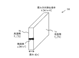
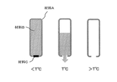
仕切り部材は組電池を構成する単電池間を仕切る。図1は、仕切り部材を例示する図である。図1には、縦、横、厚み(幅)を有する直方体(板体)の仕切り部材1(図1の説明において、仕切り部材1Aと称する)が例示されている。仕切り部材1Aは、厚み方向において反対方向を向いた2つの面1a及び面1bを有している。
A partition member partitions between the single cells which comprise an assembled battery. FIG. 1 is a diagram illustrating a partition member. FIG. 1 illustrates a rectangular parallelepiped (plate) partition member 1 (referred to as a partition member 1A in the description of FIG. 1) having vertical, horizontal, and thickness (width). The partition member 1A has two
仕切り部材1Aは、組電池を構成する単電池間を仕切るため、単電池間に配置される。仕切り部材1Aが単電池間を仕切る状態において、面1a及び面1bのそれぞれは、仕切り対象の単電池と対向した状態にされる。このとき、面1a及び面1bのそれぞれは対向する単電池と接触する状態であっても近接する状態であってもよい。
1 A of partition members are arrange | positioned between single cells in order to partition between the single cells which comprise an assembled battery. In a state in which the partition member 1A partitions the cells, each of the
図1に示す例では、面1a及び面1bを「組電池を構成する単電池間を仕切る厚み方向の二面」として使用し得る。但し、仕切り部材1Aを用いた仕切り方によっては、「組電池を構成する単電池間を仕切る厚み方向の二面」の一方は単電池と対向しない場合もあり得る。
In the example shown in FIG. 1, the
本発明において、仕切り部材の単位面積当たりの熱抵抗(θ)とは、仕切り部材の厚み方向の単位断面積あたりの熱移動抵抗を意味する。仕切り部材の単位面積当たりの熱抵抗(θ)は、仕切り部材として使用される材料の厚み方向における熱伝導率(k[W/m・K])及び仕切り部材の厚み(d[m])を用いて表すことができる。 In the present invention, the thermal resistance (θ) per unit area of the partition member means a heat transfer resistance per unit cross-sectional area in the thickness direction of the partition member. The thermal resistance (θ) per unit area of the partition member is the thermal conductivity (k [W / m · K]) in the thickness direction of the material used as the partition member and the thickness (d [m]) of the partition member. Can be used.
図1に示す仕切り部材1Aの単位面積当たりの熱抵抗(θ)について説明する。説明を簡単にするため、仕切り部材1Aは単一の材料で形成され、密度は一定であるものとする。仕切り部材1Aの厚み方向の熱伝導率をk[W/m・K]、仕切り部材1Aの厚みをd[m]とする。また、仕切り部材1Aの面1bの表面温度の平均値をT1[℃]とし、面1aの表面温度の平均値をT2[℃]とする。The thermal resistance (θ) per unit area of the partition member 1A shown in FIG. 1 will be described. In order to simplify the description, it is assumed that the partition member 1A is made of a single material and has a constant density. The thermal conductivity in the thickness direction of the partition member 1A is k [W / m · K], and the thickness of the partition member 1A is d [m]. Further, the average value of the surface temperature of the
T2がT1より低い場合、仕切り部材1Aの面1b側と面1a側とで表面温度差T1−T2が生じている。この場合、仕切り部材1Aの単位断面積当たりの熱流量(熱流束)qは、以下の式(1)によって表すことができる。
q = k(T1−T2)/d [W/m2] ・・・(1)
ここで、熱流束(q)は、単位面積当たりの熱抵抗(θ)を用いて以下の式(2)によって表すことができる。
q = (1/θ)(T1−T2) ・・・(2)
式(1)及び式(2)から、単位面積当たりの熱抵抗(θ)は、仕切り部材1Aの厚み方向の熱伝導率(k)及び仕切り部材の厚み(d)を用いて表すことができる。即ち、単位面積当たりの熱抵抗(θ)は以下の式(3)によって表すことができる。
θ = d/k [m2・K/W] ・・・(3)If T 2 is less than T 1, the surface temperature difference T 1 -T 2 at the
q = k (T 1 −T 2 ) / d [W / m 2 ] (1)
Here, the heat flux (q) can be expressed by the following equation (2) using the thermal resistance (θ) per unit area.
q = (1 / θ) (T 1 −T 2 ) (2)
From Equation (1) and Equation (2), the thermal resistance (θ) per unit area can be expressed using the thermal conductivity (k) in the thickness direction of the partition member 1A and the thickness (d) of the partition member. . That is, the thermal resistance (θ) per unit area can be expressed by the following equation (3).
θ = d / k [m 2 · K / W] (3)
仕切り部材1の形状(構造)は、直方体に制限されない。厚み方向を有する形状であれば、仕切り部材が櫛型構造、中空構造、格子構造等を有する場合であっても、仕切り部材1の熱抵抗は上記式(3)によって表すことができる。また、仕切り部材1は、単一の材料で形成される場合に限らず、複数の材料の組み合わせによって形成されてもよい。複数の材料の組み合わせによって形成されている場合であっても、仕切り部材1の単位面積当たりの熱抵抗は上記式(3)によって表すことが可能である。材料の組み合わせは、例えば、ポリエチレン、塩素化ポリエチレン、エチレン塩化ビニルコポリマー、エチレン酢酸ビニルコポリマー、ポリ酢酸ビニル、ポリプロピレン、ポリブテン、ポリブタジエン、ポリメチルペンテン、ポリスチレン、ポリα―メチルスチレン、ポリパラビニルフェノール、ABS樹脂、SAN樹脂、AES樹脂、AAS樹脂、メタクリル樹脂、ノルボルネン樹脂、ポリ塩化ビニル、アクリル変性ポリ塩化ビニル、ポリ塩化ビニリデン、ポリアリルアミン、ポリビニルエーテル、ポリビニルアルコール、エチレンビニルアルコール共重合体、石油樹脂、熱可塑性エラストマ―、熱可塑性ポリウレタン樹脂、ポリアクリロニトリル、ポリビニルブチラール、フェノール樹脂、エポキシ樹脂、尿素樹脂、メラフィン樹脂、フラン樹脂、不飽和ポリエステル樹脂、ジアリルフタレート、グアナミン、ケトン樹脂、酢酸セルロース、セロファン、硝酸セルロース、アセチルセルロース、ナイロン、ポリアミド、ポリアセタール、ポリオキシメチレン、ポリカーボネート、ポリカーボネート/ABSアロイ、ポリカーボネート/ポリエステルアロイ、ポリフェニレンエーテル、ポリブチレンテレフタラート、ポリエチレンテレフタラート、ポリスルフォン、ポリエーテルスルフォン、ポリフェニレンサルファイド、ポリアリレート、ポリアミドイミド、ポリエーテルイミド、ポリエーテルエーテルケトン、超高分子ポリエチレン、アイソタクチックポリスチレン、液晶ポリマー、ポリイミド、フッ素樹脂、テフロン(登録商標)、4フッ化エチレンペルフルオロアルコキシビニルエーテル、4フッ化エチレン・6フッ化エチレン共重合体、ポリクロロトリフルオロエチレン、4フッ化エチレン・エチレン共重合体、ポリフッ化ビニリデン、ポリビニルフロライド、ポリアミノビスマレインイミド、ポリトリアジン、架橋ポリアミドイミド等から2以上の材料を選択し、組み合わせることができる。
The shape (structure) of the
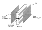
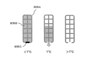
図2は、櫛型構造を有する仕切り部材1(図2の説明において、仕切り部材1Bと称する)を例示する。図2に示すように、仕切り部材1Bは、全体として板状に形成され、その断面が櫛型に形成されている。仕切り部材1Bにおいても、厚さ方向において反対方向を向いた2つの面1c及び面1dを有する。面1cは縞状の凹凸面であり、面1dは平面である。これより、厚さ方向の面で仕切り部材1Bを切断した断面は櫛形となっている。面1c及び面1dは、面1a及び面1bと同様に扱うことができる。
FIG. 2 illustrates a
図2に示す仕切り部材1Bの単位面積当たりの熱抵抗(θ)の求め方は以下の通りである。面1c及び面1dの各表面における平均温度を、上記式(1)及び式(2)のT1及びT2として用いることができる。また、当該仕切り部材1Bの単位断面積当たりの熱流量の平均値を上記式(1)及び式(2)の熱流束(q)として用いることができる。The method for obtaining the thermal resistance (θ) per unit area of the
また、熱伝導率(k)として、当該仕切り部材1Bの構造及び材料種を考慮して算出した合成熱伝導率を、上記式(1)及び式(3)の熱伝導率(k)として用いることで、単位面積当たりの熱抵抗(θ)は、上記式(3)により表すことができる。このように、単位面積当たりの熱抵抗(θ)は、仕切り部材1Bの構造及び材料種を考慮して算出される単位面積当たりの有効熱抵抗を用いることが可能である。
Further, as the thermal conductivity (k), the synthetic thermal conductivity calculated in consideration of the structure and material type of the
なお、合成熱伝導率は、例えば以下の方法により算出することができる。まず、熱伝導率:kn[W/m・K]、厚み:dn[m]、熱抵抗:Rn(n=1,2,・・・n)のn種類の材料を組み合わせた複合部材の熱抵抗(R)を求める。n種類の材料が直列で並んでいる場合、熱抵抗(R)は、以下の式(4)によって表すことができる。
R=R1+R2+R3+・・・+Rn ・・・(4)
また、n種類の材料が並列で並んでいる場合は、熱抵抗(R)は、以下の式(5)によって表すことができる。
1/R=1/R1+1/R2+1/R3+・・・+1/Rn ・・・(5)The synthetic thermal conductivity can be calculated by the following method, for example. First, the thermal conductivity: k n [W / m · K], thickness: d n [m], the thermal resistance: R n (n = 1,2, ··· n) a combination of n kinds of material of the composite The thermal resistance (R) of the member is obtained. When n types of materials are arranged in series, the thermal resistance (R) can be expressed by the following equation (4).
R = R 1 + R 2 + R 3 +... + R n (4)
When n types of materials are arranged in parallel, the thermal resistance (R) can be expressed by the following equation (5).
1 / R = 1 / R 1 + 1 / R 2 + 1 / R 3 +... + 1 / R n (5)
次に、n種類の材料が直列で並んでいる場合の複合部材の合成熱伝導率を算出する。この場合、n種類の材料の熱移動方向の断面積(An)は全て等しいものとする。即ち、A1=A2=A3=・・・=An=A[m2]とすると、各材料の熱抵抗(Rn)は、単位断面積あたりの熱抵抗(θn)を用いて以下の式(6)によって表される。
Rn=θn/A ・・・(6)
式(4)を式(6)及び式(3)を用いて変形すると、以下の式(7)が得られる。
R=(θ1+θ2+θ3+・・・+θn)/A
=(d1/k1+d2/k2+d3/k3+・・・+dn/kn)/A ・・・(7)
複合部材の合成熱伝導率をκとすると、複合部材の総厚みはΣdnであるから、合成熱伝導率(κ)は、以下の式(8)のように表すこともできる。
R=(Σdn/κ)/A ・・・(8)
式(7)及び式(8)より、合成熱伝導率(κ)は、以下のように表すことができる。
κ=Σdn/Σ(dn/kn)
=(d1+d2+d3+・・・+dn)/(d1/k1+d2/k2+d3/k3+・・・+dn/kn)Next, the composite thermal conductivity of the composite member when n types of materials are arranged in series is calculated. In this case, the cross-sectional areas (A n ) in the heat transfer direction of the n kinds of materials are all equal. That is, when A 1 = A 2 = A 3 =... = A n = A [m 2 ], the thermal resistance (R n ) of each material uses the thermal resistance (θ n ) per unit cross-sectional area. Is expressed by the following equation (6).
R n = θ n / A (6)
When Expression (4) is transformed using Expression (6) and Expression (3), the following Expression (7) is obtained.
R = (θ 1 + θ 2 + θ 3 +... + Θ n ) / A
= (D 1 / k 1 +
When the composite thermal conductivity of the composite member and kappa, because the total thickness of the composite member is a [Sigma] d n, synthetic thermal conductivity (kappa) can also be expressed as the following equation (8).
R = (Σd n / κ) / A (8)
From the equations (7) and (8), the synthetic thermal conductivity (κ) can be expressed as follows.
κ = Σd n / Σ (d n / k n )
= (D 1 + d 2 +
また、n種類の材料が並列で並んでいる場合の複合部材の合成熱伝導率を算出する。この場合、n種類の材料の熱移動方向の厚みは全て等しいものとする。即ち、d1=d2=d3=・・・=dn=d[m]とする。n種類の材料の熱移動方向の断面積をそれぞれAn[m2]とすると、各材料の熱抵抗(Rn)は単位断面積あたりの熱抵抗(θn)を用いて次のように表せる。
Rn=θn/An ・・・(9)
式(5)を式(9)及び式(3)を用いて変形すると、以下の式(10)が得られる。
1/R=A1/θ1+A2/θ2+A3/θ3+・・・+An/θn
=(A1k1+A2k2+A3k3+・・・+Ankn)/d ・・・(10)
複合部材の合成熱伝導率をκとすると、複合部材の総断面積はΣAnであるから、合成熱伝導率(κ)は、以下の式(11)のように表すこともできる。
R=(d/κ)/ΣAn ・・・(11)
式(10)及び式(11)より、合成熱伝導率(κ)は、以下のように表すことができる。
κ=Σ(Ankn)/ΣAn
=(A1k1+A2k2+A3k3+・・・+Ankn)/(A1+A2+A3+・・・+An)Further, the composite thermal conductivity of the composite member when n types of materials are arranged in parallel is calculated. In this case, the thicknesses of the n kinds of materials in the heat transfer direction are all equal. That is, d 1 = d 2 = d 3 =... = D n = d [m]. When n types of material of cross-sectional area of the heat transfer direction, respectively, and A n [m 2], the thermal resistance (R n) of each material with a heat resistance per unit cross-sectional area (theta n) is as follows I can express.
R n = θ n / A n (9)
When Expression (5) is transformed using Expression (9) and Expression (3), the following Expression (10) is obtained.
1 / R = A 1 / θ 1 + A 2 / θ 2 + A 3 / θ 3 +... + A n / θ n
= (A 1 k 1 + A 2 k 2 + A 3 k 3 +... + A n k n ) / d (10)
When the composite thermal conductivity of the composite member and kappa, because the total cross-sectional area of the composite member is .SIGMA.A n, synthetic thermal conductivity (kappa) can also be expressed as the following equation (11).
R = (d / κ) / ΣAn (11)
From the equations (10) and (11), the synthetic thermal conductivity (κ) can be expressed as follows.
κ = Σ (A n k n ) / ΣA n
= (A 1 k 1 + A 2 k 2 + A 3 k 3 +... + A n k n ) / (A 1 + A 2 + A 3 +... + A n )
仕切り部材1Bのような櫛形構造の仕切り部材であっても、中空構造、格子構造等の仕切り部材であっても、空洞部位の材質である空気の熱伝導率および空洞部位の厚みや断面積を与えることで、合成熱伝導率を算出することができる。
Whether the partition member is a comb-shaped partition member such as the
仕切り部材1の組電池を構成する単電池間を仕切る厚み方向の二面のうちの一方(例えば、面1a〜1dのいずれか)の平均温度が180℃を超える場合においては、その厚み方向の熱伝導率が2.0×10⁻²W/m・K以上2.0W/m・K以下であり、かつ、前記面(例えば、面1a〜1dのいずれか)の平均温度が80℃を超えない場合においては、その厚み方向の熱伝導率が5.0×10−2W/m・K以上50W/m・K以下である、ようにするのが好ましい。When the average temperature of one of the two surfaces in the thickness direction partitioning the cells constituting the assembled battery of the partition member 1 (for example, any one of the
また、組電池を構成する単電池の厚みがL[mm]である場合に、厚みがL/50mm以上L/10mm以下であることが好ましい。ここで、組電池を構成する単電池の厚み(L)について想定される範囲は、通常、10mm≦L≦100mm、好ましくは15mm≦L≦80mmである。 Moreover, when the thickness of the unit cell constituting the assembled battery is L [mm], the thickness is preferably L / 50 mm or more and L / 10 mm or less. Here, the range assumed about the thickness (L) of the unit cell constituting the assembled battery is usually 10 mm ≦ L ≦ 100 mm, preferably 15 mm ≦ L ≦ 80 mm.
なお、ある仕切り部材が本発明の仕切り部材に該当するかどうかの確認は以下のように行えばよい。 In addition, what is necessary is just to confirm whether a certain partition member corresponds to the partition member of this invention as follows.
[1.熱抵抗(θ1)の決定]
1−1)確認の対象とする仕切り部材の重心を決める。そしてこの重心から仕切り部材の一方の面に対して垂線を引き、その交点となる点を第1の点とする。この第1の点を含む面全体が160℃加熱となるように加熱する。なお、この加熱方法はある第1の点を含む面全体を160〜300℃となるように温度を制御して加熱することができる方法であればその方法は制限されない。
1−2)第1の点を基準として、前記仕切り部材を前記厚み方向に二等分する分割面に対して前記第1の点と面対称の位置にある、他方の面上に存在する点を第2の点とする。
1−3)第1の点及び第2の点に基づいて、第1の点を含む面の温度について160℃から300℃まで昇温させる。ここで、160℃、180℃、210℃、240℃、270℃及び300℃のそれぞれの温度で系全体の温度が定常状態となったときについて、前述の方法により熱抵抗(θ1)を求める。[1. Determination of thermal resistance (θ 1 )]
1-1) Determine the center of gravity of the partition member to be checked. A perpendicular line is drawn from the center of gravity to one surface of the partition member, and a point that is the intersection is defined as a first point. The entire surface including the first point is heated to 160 ° C. Note that this heating method is not limited as long as the entire surface including a certain first point can be heated by controlling the temperature so as to be 160 to 300 ° C.
1-2) A point existing on the other surface that is symmetrical to the first point with respect to the dividing surface that bisects the partition member in the thickness direction with respect to the first point. Is the second point.
1-3) Based on the first point and the second point, the temperature of the surface including the first point is increased from 160 ° C. to 300 ° C. Here, the thermal resistance (θ 1 ) is obtained by the above-described method when the temperature of the entire system becomes a steady state at each temperature of 160 ° C., 180 ° C., 210 ° C., 240 ° C., 270 ° C. and 300 ° C. .
[2.熱抵抗(θ2)の決定]
2−1)前記第1の点を含む面について面全体を100℃に加熱する。なお、この加熱方法は前記第1の点を含む面全体を20〜1000℃となるように温度を制御して加熱することができる方法であればその方法は制限されない。
2−2)1−2)と同様にして第2の点を決定する。
2−3)第1の点及び第2の点に基づいて、第1の点を含む面について100℃から20℃まで降温させる。ここで、80℃、60℃、40℃、20℃のそれぞれの温度で系全体の温度が定常状態となったときについて、前述の方法により熱抵抗(θ2)を求める。[2. Determination of thermal resistance (θ 2 )]
2-1) The entire surface including the first point is heated to 100 ° C. The heating method is not limited as long as the entire surface including the first point can be heated at a temperature of 20 to 1000 ° C.
2-2) The second point is determined in the same manner as in 1-2).
2-3) Based on the first point and the second point, the temperature including the first point is lowered from 100 ° C. to 20 ° C. Here, the thermal resistance (θ 2 ) is obtained by the above-described method when the temperature of the entire system becomes a steady state at each temperature of 80 ° C., 60 ° C., 40 ° C., and 20 ° C.
[3.仕切り部材の確認]
3−1)上記1−3)及び2−3)で求めた熱抵抗の値を用い、180℃より高い温度の各温度において上記式1を満たすかどうか、及び80℃よりも低い温度の各温度において上記式2を満たすかどうかを確認する。これらの各温度において式1及び式2を満たすかどうかを確認することにより、ある仕切り部材が本発明の仕切り部材に該当するかどうかを確認する。なお、前述の通り、本発明の仕切り部材は160℃より高い温度の各温度において上記式1を満たすことが好ましく、100℃より低い温度の各温度において上記式2を満たすことが好ましい。[3. Confirmation of partition member]
3-1) Using the value of the thermal resistance obtained in 1-3) and 2-3) above, whether each of the temperatures higher than 180 ° C. satisfies
<組電池>
仕切り部材1は、組電池を構成する構成要素の一つである。本発明に適用し得る組電池は、例えば、電気自動車(EV、Electric Vehicle)、ハイブリッド電気自動車(HEV、Hybrid Electric Vehicle)、プラグインハイブリッド電気自動車(PHEV、Plug−in Hybrid Electric Vehicle)、電動重機、電動バイク、電動アシスト自転車、船舶、航空機、電車、無停電電源装置(UPS、Uninterruptible Power Supply)、家庭用蓄電システム、風力/太陽光/潮力/地熱等の再生可能エネルギーを利用した電力系統安定化用蓄電池システム等に搭載される電池パックに適用される。但し、組電池は、上述のEV等以外の機器に電力を供給する電力源としても使用し得る。<Battery assembly>
The
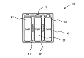
図3は、組電池を例示する図である。図3には、組電池10として、3セル連結簡易組電池が例示されている。組電池は、所望の出力電力に応じた数の単電池(セルともいう)が直列、並列、又はこれらの組合せにより接続されて形成される。セルの数は、要求される電力に応じて適宜設定される。図3の例では、各単電池が直列に接続され、単電池間に仕切り部材が配置される。
FIG. 3 is a diagram illustrating an assembled battery. In FIG. 3, a three-cell connection simple assembled battery is illustrated as the assembled
図3に示す組電池10の例示では、組電池10は、セル21(Cell1:第1単電池)、セル22(Cell2:第2単電池)、セル23(Cell3:第3単電池)と、セル間に配置されてセル間を仕切る仕切り部材11(Spacer1:第1仕切り部材)、仕切り部材12(Spacer2:第2仕切り部材)と、を含む。組電池10は、さらにバスバー3及び筐体4を備える。以下の説明において、仕切り部材11と仕切り部材12とを区別しない場合は、仕切り部材1と称する。また、セル21,セル22,セル23を区別しない場合は、セル2との表記を用いる。なお、本発明において、第1単電池、第2単電池及び第3単電池、並びに第1仕切り部材及び第2仕切り部材とは、図3に示されるような相対的な位置関係を意味するものであり、ある単電池が異常発熱状態に至った場合、当該単電池を第1単電池とみなして第2単電池及び第3単電池、並びに第1仕切り部材及び第2仕切り部材を決定するものとする。
In the illustration of the assembled
(セル/単電池)
セル2は、例えば、リチウムイオンを吸蔵・放出可能な正極及び負極、並びに電解質を備えるリチウムイオン二次電池である。リチウムイオン二次電池以外に、リチウムイオン全固体電池、ニッケル水素電池、ニッケルカドミウム電池、鉛蓄電池等の二次電池を適用し得る。(Cell / cell)
The
(仕切り部材)
仕切り部材1は、図1及び図2を用いて説明したものを適用することができる。(Partition member)
As the
(バスバー、筐体)
バスバー3は、セルから出力される電力を負荷(例えば、モータ)へ供給するために使用される導体棒であり、例えばアルミニウム等の導体で形成される。筐体4は、仕切り部材1及びセル2を収容する。筐体4は、例えば、金属、樹脂(ポリプロピレン等)、金属及び樹脂の組み合わせで形成し得る。筐体として、セル間に仕切り部材1が挿入された複数のセル2のエンドプレートで挟み、エンドプレート間を接続板で接続して、セル2及び仕切り部材1が固定されるようにしてもよい。(Bus bar, housing)
The
<組電池における発熱及び熱移動>
セル2を構成する電極や電解液等を構成する化学物質の一部ないし全てが、セル2内部で発熱を伴いながら分解反応を起こすことにより、セル2の温度が昇温し、セル2の一部ないし全領域が200℃以上になる場合がある。この状態を「異常発熱状態」という。<Heat generation and heat transfer in battery pack>
Some or all of the chemical substances constituting the electrodes, electrolyte, etc. constituting the
一般に、セル2を構成する材料のうち正極材料の安全性について、充電による脱リチウム後の結晶構造の安定性が大きく影響していることが知られている。正極材料として一般に用いられるLiCoO2、Li(Ni1/3Mn1/3Co1/3)O2、Li(Ni0.8Co0.15Al0.05)O2等の材料は、充電状態では高温下で、酸素放出を伴う結晶崩壊を起こす。正極から放出された酸素は電解液の酸化等を引き起こし、急激な発熱反応を伴う。放射光を用いた構造解析により、上記正極材料種では200℃付近で結晶の相転移が起こることが報告されている。このため、セル2の一部ないし全領域が200℃以上になる場合、正極の結晶崩壊が進行している、つまりセル2が熱暴走状態にあることを意味する(参考文献1:リチウムイオン電池の高安全技術と材料 シーエムシー出版、P.44/参考文献2:J.Dahn et al., Electrochemistry Communication, 9, 2534−2540 (2007)/参考文献3:小林弘典、「放射光を用いたリチウムイオン二次電池用正極材料の評価・解析技術」Spring−8利用推進協議会 ガラス・セラミックス研究会(第二回)(2011))。In general, it is known that the stability of the crystal structure after delithiation by charging is greatly affected by the safety of the positive electrode material among the materials constituting the
また、セル2を構成する材料のうち負極材料の安全性について、充電負極(リチウム挿入炭素負極)は基本的にリチウム金属と同様の強い還元性を示し、電解液との反応で負極表面上に被膜が形成され、それによってさらなる反応が抑制されていることが知られている。従って、その保護被膜の化学的組成や構造、熱安定性が温度上昇時の充電負極の熱安定性に多大な影響を与える。通常、充電負極と電解液との反応は、保護被膜の形成と、それに続く被膜破壊による爆発的な還元分解反応により説明される。一般に、負極上での保護被膜形成反応は130℃付近から、引き続く被膜分解反応が200℃付近で進行し、最終的に爆発的還元分解反応に至ることが報告されている。このため、セル2の一部ないし全領域が200℃以上になる場合、負極表面の被膜破壊が進行している、つまりセル2が熱暴走状態にあることを意味する(参考文献4:電池ハンドブック第1版 オーム社、P.591/参考文献5:リチウムイオン電池の高安全技術・評価技術の最前線 シーエムシー出版、P.90)。
In addition, regarding the safety of the negative electrode material among the materials constituting the
また、セル2を構成する電極や電解液等を構成する化学物質が、セル2内部で一定以上の発熱速度を伴う分解反応を起こしていない状態を、「通常状態」という。ここで、反応性化学物質が断熱条件下で自己発熱分解する際の熱的挙動を定量的に測定する手段であるARC(Accelerating rate calorimetry)を用いて、セル2の発熱状態を評価することができる。例えばDahnらは、ARCにおいて観測される発熱速度が0.04℃/minを上回る場合に、セル内部で自己発熱反応が進行しているものと定義しており、これに倣うことができる(参考文献6:J.Dahn et al., Electrochimica Acta, 49, 4599−4604 (2004))。また、通常状態のセル2を、「通常状態を保持している単電池」、通常状態を逸脱し異常発熱状態に至っていないセル2を、「通常状態を逸脱した単電池」という。セル2内部での発熱は、各種伝達経路を介して、他のセル2に伝達される。
In addition, a state in which the chemical substances constituting the electrodes, electrolyte solution, and the like constituting the
また、通常状態のセル2を、「通常状態を保持している単電池」、通常状態を逸脱し異常発熱状態に至っていないセル2を、「通常状態を逸脱した単電池」という。セル2内部での発熱は、各種伝達経路を介して、他のセル2に伝達される。
Further, the
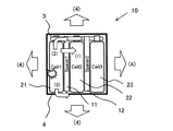
図4は、組電池の伝熱経路を例示する図である。図4の例において、組電池10を構成する左端のセル21が異常発熱した場合、セル21で発生した熱は、(1)セル間に配置される仕切り部材11、(2)バスバー3、及び(3)セル2と接触する組電池10の筐体4、を介して他のセル22、23に移動する他、(4)組電池10の筐体外部にも放熱される。
FIG. 4 is a diagram illustrating a heat transfer path of the assembled battery. In the example of FIG. 4, when the
仕切り部材1に接触又は近接するセル2が通常状態を逸脱し、異常発熱状態に至っていない場合に想定される表面平均温度の上限値は180℃とする。ここで、汎用セパレータ材のメルトダウン温度は160〜200℃であることが知られている。このため、セル2の表面平均温度が180℃を超える場合には、セル2を構成する汎用セパレータ材の一部がメルトダウンし、異常発熱状態に至る危険性がある。仕切り部材1の、組電池10を構成するセル2間を仕切る厚み方向の二面のうちの一方の平均温度が180℃を超える場合に、熱抵抗(θ1)が前記(式1)を満たすように制御することで、仕切り部材1を介する熱移動が制限され、仕切り部材1に接触又は近接するセル2への延焼を抑制することができる。汎用セパレータ材の材質は、例えば、ポリエチレン、ポリプロピレン等である(参考文献7:特開2013−35293号公報/参考文献8:特開2015−208894号公報)。The upper limit of the surface average temperature assumed when the
仕切り部材1に接触又は近接するセル2が通常状態を逸脱していない場合に想定される表面平均温度の上限値は80℃とする。ここで、汎用電解液成分の沸点は、下記表1に示すように90℃以上である。汎用電解液成分は、例えば、エチレンカーボネート(EC)、ジエチルカーボネート、ジメチルカーボネート(DMC)、エチルメチルカーボネート(EMC)である。セル2の表面平均温度が80℃より低い場合は、セル2を構成する汎用電解液自体の沸騰には至らない。仕切り部材1の、組電池を構成する単電池間を仕切る厚み方向の二面の双方の平均温度が80℃よりも低い場合は、熱抵抗(θ2)が前記(式2)を満たすように制御することで、仕切り部材1を介する熱移動は促進される。全てのセル2が通常状態である場合、仕切り部材1の熱移動抵抗が従来品より低いため、組電池10内のセル2間の均温化に奏功し、温度ムラによるセル2の劣化を軽減する効果が期待できる。The upper limit value of the surface average temperature assumed when the

<単位面積当たりの熱抵抗(θ)の制御手段>
仕切り部材1の表面温度によって単位面積当たりの熱抵抗(θ)を制御する手段について説明する。まず、仕切り部材1を構成する材料A及び材料Bを以下に例示する。<Measuring means for thermal resistance per unit area (θ)>
A means for controlling the thermal resistance (θ) per unit area according to the surface temperature of the
材料Aは、単位面積当たりの熱抵抗(θ)が前記(式1)を満たす材料である。材料Aは、熱伝導率:k≦0.20[W/m・K]、厚み:d=1.0[mm]とする。即ち、単位面積当たりの熱抵抗:θ=d/k≧(1.0×10−3)/0.20=5.0×10−3[m2・K/W]である。材料Aは、例えば、ポリカーボネートやブチルゴム製の樹脂板等である。The material A is a material in which the thermal resistance (θ) per unit area satisfies the above (Formula 1). The material A has thermal conductivity: k ≦ 0.20 [W / m · K] and thickness: d = 1.0 [mm]. That is, thermal resistance per unit area: θ = d / k ≧ (1.0 × 10 −3 ) /0.20=5.0×10 −3 [m 2 · K / W]. The material A is, for example, a resin plate made of polycarbonate or butyl rubber.
また、材料Bは、単位面積当たりの熱抵抗(θ)が前記(式2)を満たす材料である。材料Bは、熱伝導率:k≧0.25[W/m・K]、厚み:d=1.0[mm]とする。即ち、単位面積当たりの熱抵抗:θ=d/k≦(1.0×10−3)/0.25=4.0×10−3[m2・K/W]である。材料Bは、例えば、固体ではセラミックス、ガラス板、ポリエチレン等であり、液体では水、エチレングリコール、グリセリン等である。The material B is a material in which the thermal resistance (θ) per unit area satisfies the above (Formula 2). The material B has thermal conductivity: k ≧ 0.25 [W / m · K] and thickness: d = 1.0 [mm]. That is, thermal resistance per unit area: θ = d / k ≦ (1.0 × 10 −3 ) /0.25=4.0×10 −3 [m 2 · K / W]. The material B is, for example, ceramic, glass plate, polyethylene or the like in the solid state, and water, ethylene glycol, glycerin or the like in the liquid state.
単位面積当たりの熱抵抗(θ)が温度T[℃]以上で上記(式1)を満たし、かつT[℃]未満で上記(式2)を満たす仕切り部材1として、以下に2つの例を示す。第1の例では、仕切り部材1は、T[℃]より高い温度に融点を持つ材料Aで形成された内部が中空の略直方体の袋状構造物を含む(図5)。袋状構造物の内部には、T[℃]において液体状態である材料Bが充填され、袋状構造物の下面には、その内部と外部とを連通する開口部が設けられ、開口部は、例えばT[℃]付近に融点を持つ材料Cで形成される栓で閉じられている。T[℃]付近において、材料Cで形成された栓が溶融した場合に開口部が形成され、内部に充填された材料Bが開口部から外部に流れ落ちるように設計されている。袋状構造物の外形形状は、直方体以外の形状を有していてもよい。また、図5では、開口部は袋状構造物の下面に設けられるが、開口部から材料Bが袋状構造物の外部に流れ落ちる位置であれば、開口部は側面に設けられてもよい。なお、仕切り部材1は、上述した材料Bが充填された複数の袋状構造物が横方向又は縦方向に並べて形成された構造であってもよい。また、栓は必ずしも必須でない。材料Cの融点は材料Bと同等かそれ以下でもよい。栓を材料Bで形成する場合もあり得る。材料Bは必ずしもT[℃]において液体で無くてもよく、液体以外の流体状態である場合もあり得る。
Two examples of the
上記のような袋状構造物の仕切り部材1であれば、表面温度がT[℃]未満の場合には、袋状構造物内の材料Bによって単位面積当たりの熱抵抗(θ)は上記(式2)を満たす。また、仕切り部材1の表面温度がT[℃]以上になった場合には、材料Bが袋状構造物の外部に流れ落ちるため仕切り部材1は材料Aで構成されることになり、仕切り部材1の単位面積当たりの熱抵抗(θ)は上記(式1)を満たす。
In the case of the
次に、第2の例を説明する。第2の例では、仕切り部材1は、図5の袋状構造物の内部に格子状のフレームが設けられた構造を有する(図6)。袋状構造物の内部において、フレーム以外の部分は、T[℃]において液体状態である材料Bで満たされ、袋状構造物の下面は、T[℃]付近に融点を持つ材料Cで形成される栓で閉じられている。T[℃]付近において、材料Cで形成された栓が溶融した場合に、袋状構造物の空間部分に充填された材料Bが、栓の溶融により形成される開口部から外部に流れ落ちるように設計されている。フレームは、材料Bが流れ出た場合における袋状構造物の剛性(強度)を維持するように作用する。このような袋状構造物の仕切り部材1であれば、表面温度がT[℃]未満の場合には、袋状構造物の空間部分に充填された材料Bによって単位面積当たりの熱抵抗(θ)は上記(式2)を満たす。また、仕切り部材1の表面温度がT[℃]以上になった場合には、材料Bが袋状構造物の外部に流れ落ちるため仕切り部材1は材料Aで構成されることになり、仕切り部材1の単位面積当たりの熱抵抗(θ)は上記(式1)を満たす。
Next, a second example will be described. In the second example, the
<セル間の熱移動制御>
組電池10を構成するセル2間の熱移動は、異常発熱状態に至ったセル2から通常状態を逸脱したセル2へ伝わる熱量を抑制しつつ、異常発熱状態に至ったセル2から通常状態を逸脱したセル2の電極体を介さずに通常状態を保持しているセル2に伝わる熱量、及び通常状態を逸脱したセル2から通常状態を保持しているセル2へ伝わる熱量は抑制しないように制御される。なお、セル2の電極体は、電極、セパレータ、電解液を含む構造体、即ち電池の本体である。<Control of heat transfer between cells>
The heat transfer between the
例えば、図4において、セル21が異常発熱状態に至り、セル22は通常状態を逸脱し、セル23は通常状態を保持しているものと想定する。この場合、セル21からセル22へ伝わる熱量は抑制され、セル21からセル22の電極体を介さずにセル23に伝わる熱量及びセル22からセル23に伝わる熱量は抑制されないように制御される。
For example, in FIG. 4, it is assumed that the
セル2間の熱移動は、仕切り部材1のスイッチング機能により、制御することができる。即ち、通常状態を逸脱したセル22と異常発熱状態に至ったセル21の間に設置された仕切り部材11の熱移動抵抗が増加することにより、セル21が発した熱量のうちセル22へ伝わる熱量が減少する。また、通常状態を逸脱したセル22と通常状態を保持しているセル23の間に設置された仕切り部材12の熱移動抵抗が増加しないことにより、セル22からセル23へ伝わる熱量、及びセル21が発した熱量のうちセル22の電極体を介さずにセル23へ伝わる熱量は減少しない。なお、セル21が発した熱量のうち、セル22の電極体を介さずにセル23へ伝わる熱量は、仕切り部材1以外の、セル22の電極体を除くセル2乃至組電池10の構造体(例えば、バスバー3及び筐体4の外壁等)を介して伝えられる。
The heat transfer between the
このように、本実施形態の仕切り部材1によれば、異常発熱状態に至ったセル21が発した熱量は、通常状態を逸脱したセル22に伝わる熱量を抑制しつつ、通常状態を保持しているセル23に伝わるように制御され、組電池10内の各セル2の温度は均温化される。したがって、異常発熱状態に至ったセル2以外のセル2が異常発熱状態に至ることを抑制することが可能となる。
Thus, according to the
次に実施例により本発明の具体的態様を更に詳細に説明するが、本発明はこれらの例によって限定されるものではない。 EXAMPLES Next, specific embodiments of the present invention will be described in more detail with reference to examples, but the present invention is not limited to these examples.
以下の各実施例及び比較例では、異常発熱したセルからの他のセルへの伝熱経路のうち、セル間に配置される仕切り部材1を介する熱移動に着目し、仕切り部材1によるセル間の延焼抑制の可能性を検討した。評価対象の組電池として、図3に示す2次元座標系3セル連結簡易組電池モデルを構築し、左端部のセル21に熱暴走発生時相当の発熱量1.3×10⁹[J/m3](NMC系正極を用いたセル2の熱量評価から推定される総発熱量)を与え、以下の各実施例及び比較例の条件において、熱伝導方程式を有限要素法により解くことにより、各セル2内の温度、並びに仕切り部材1の表面平均温度及び単位面積当たりの熱抵抗を推算した。ここで、解析にはCOMSOL AB社製の汎用物理シミュレーションソフトウエアであるCOMSOL Multiphysicsを用い、下記参考文献9、10を参照して解析した。なお、セル間の伝熱経路については、図4で説明した経路が想定される(参考文献9:特開2006−010648号公報/参考文献10:R.M.Spotnitz et al., J.Power Sources 163, 1080−1086,(2007))。In each of the following examples and comparative examples, attention is paid to heat transfer through the
また、図3において、左端部のセル21が異常発熱した場合に、隣接するセル22及びセル23の内部の温度、並びに仕切り部材1の表面平均温度及び単位面積当たりの熱抵抗を推算し、仕切り部材1の熱移動抵抗の変化による延焼抑制等の効果を評価した。なお、各セル2の内部の温度は、電極体(電極、セパレータ、電解液を含む構造体)の内部平均温度を計測したものと想定した。
Further, in FIG. 3, when the
(比較例1)
比較例1では、仕切り部材1は、ポリプロピレン(PP)等の一般的な樹脂製であるものと想定し、膜厚は1mm、熱伝導率は0.24W/m・Kとした。バスバー3は、アルミニウム製であるものと想定し、熱伝導率は237W/m・Kとした。筐体4は、ポリプロピレン等の一般的な樹脂製であるものと想定し、熱伝導率は0.24W/m・Kとした。これらの条件下で、各セル2内の温度、並びに仕切り部材1の表面平均温度及び単位面積当たりの熱抵抗を推算した。(Comparative Example 1)
In Comparative Example 1, it is assumed that the
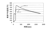
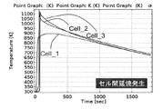
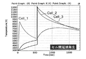
図7は、比較例1におけるセルの内部の温度変化を示すグラフである。縦軸はセル2内部の絶対温度[K]、横軸はセル21が異常発熱状態に至ってからの時間[秒]を示す。セル21が異常発熱状態に至ってから約150秒後には、セル22及びセル23の内部の温度は1000Kを超え、異常発熱したセル21からセル22及びセル23への延焼が発生することが示唆された。
FIG. 7 is a graph showing the temperature change inside the cell in Comparative Example 1. The vertical axis represents the absolute temperature [K] inside the
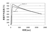
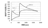
図8は、比較例1における仕切り部材の表面平均温度の推移を示すグラフである。なお、仕切り部材1の表面平均温度は、異常発熱したセル21側の表面における平均温度とした。縦軸は仕切り部材1の表面平均温度[℃]、横軸はセル21が異常発熱状態に至ってからの時間[秒]を示す。セル21が異常発熱状態に至った直後から仕切り部材11(Spacer1)の表面平均温度は急上昇して400℃に達しており、約150秒後には、仕切り部材12(Spacer2)の表面平均温度も急上昇して700℃を超えることが推算された。
FIG. 8 is a graph showing the transition of the average surface temperature of the partition member in Comparative Example 1. The average surface temperature of the
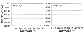
図9は、比較例1における仕切り部材の単位面積当たりの熱抵抗の推移を示すグラフである。縦軸は単位面積当たりの熱抵抗(m2・K/W)、横軸は仕切り部材1の表面平均温度(℃)を示す。仕切り部材11(Spacer1)及び仕切り部材12(Spacer2)の表面平均温度190℃における単位面積当たりの熱抵抗(θ1)の値は4.2×10−3m2・K/W、平均温度70℃における単位面積当たりの熱抵抗(θ2)の値は4.2×10−3m2・K/Wであった。即ち、比較例1における仕切り部材1は、単位面積当たりの熱抵抗に関する上述の(式1)及び(式2)のいずれの条件も満たさない。FIG. 9 is a graph showing the transition of thermal resistance per unit area of the partition member in Comparative Example 1. The vertical axis represents the thermal resistance per unit area (m 2 · K / W), and the horizontal axis represents the surface average temperature (° C.) of the
(実施例1)
実施例1では、仕切り部材1は、異常発熱したセル側の表面温度が所定温度に達した時点で熱伝導率が変化するスイッチング機能を有する高機能仕切り部材であるものと想定し、膜厚は1.0mmとした。バスバー3及び筐体4についての各種条件は、比較例1と同様とした。(Example 1)
In Example 1, the
スイッチング機能を有する仕切り部材1は、例えば、前述の材料Aの内、150℃付近に融点を持つ材料で構成される袋状構造物の内部に、前述の材料Bの内、150℃において液体状態である物質を封入し、150℃において材料Aで構成される袋状構造物の一部が溶融した場合に、内部に封入された材料Bが袋状構造物の外部に流れ落ちるように設計された構造物とすることができる。このような構造物により、仕切り部材1のスイッチング温度を150℃、初期熱伝導率を1.0W/m・K、スイッチング後の熱伝導率を0.10W/m・Kとし、各セル2内の温度、並びに仕切り部材1の表面平均温度及び単位面積当たりの熱抵抗を推算した。
The
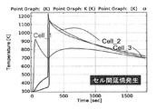
図10は、実施例1におけるセルの内部の温度変化を示すグラフである。縦軸はセル2内部の絶対温度[K]、横軸はセル21が異常発熱状態に至ってからの時間[秒]を示す。セル21が異常発熱状態に至ってから、セル22及びセル23の内部の温度は徐々に上昇するものの、異常発熱状態に至ることなく、約430K前後に収束しており、セル2間の延焼を抑制できる可能性があることが示された。
FIG. 10 is a graph showing the temperature change inside the cell in Example 1. The vertical axis represents the absolute temperature [K] inside the
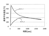
図11は、実施例1における仕切り部材の表面平均温度の推移を示すグラフである。縦軸は仕切り部材1の表面平均温度(℃)、横軸はセル21が異常発熱状態に至ってからの時間[秒]を示す。セル21が異常発熱状態に至った直後から仕切り部材11(Spacer1)の表面平均温度は急上昇して400℃を超えるが、仕切り部材12(Spacer2)の表面平均温度は急上昇することなく約160℃に収束することが推算された。
FIG. 11 is a graph showing the transition of the average surface temperature of the partition member in Example 1. The vertical axis represents the average surface temperature (° C.) of the
図12は、実施例1における仕切り部材の単位面積当たりの熱抵抗の推移を示すグラフである。縦軸は単位面積当たりの熱抵抗[m2・K/W]、横軸は仕切り部材1の表面平均温度[℃]を示す。仕切り部材11(Spacer1)及び仕切り部材12(Spacer2)の表面平均温度190℃における単位面積当たりの熱抵抗(θ1)の値は1.0×10−2m2・K/W、平均温度70℃における単位面積当たりの熱抵抗(θ2)の値は1.0×10−3m2・K/Wであった。即ち、実施例1における仕切り部材1は、単位面積当たりの熱抵抗に関する上述の(式1)及び(式2)のいずれの条件も満たしている。FIG. 12 is a graph showing changes in thermal resistance per unit area of the partition member in Example 1. The vertical axis represents the thermal resistance per unit area [m 2 · K / W], and the horizontal axis represents the surface average temperature [° C.] of the
(比較例2)
比較例2及び比較例3は、仕切り部材1のスイッチング機能の重要性を確認するため、スイッチング機能を持たない仕切り部材1を想定した例を示す。比較例2では、仕切り部材1は、比較例1よりも熱伝導率が低い仕切り部材1であるものと想定し、膜厚は1.0mm、熱伝導率は0.10W/m・Kとした。バスバー3及び筐体4についての各種条件は、比較例1と同様とした。(Comparative Example 2)
Comparative Example 2 and Comparative Example 3 show examples in which the
図13は、比較例2におけるセルの内部の温度変化を示すグラフである。縦軸はセル2内部の絶対温度[K]、横軸はセル21が異常発熱状態に至ってからの時間[秒]を示す。一般的な樹脂製仕切り部材1を使用する比較例1と比べて、異常発熱したセル21からセル22及びセル23への延焼が発生するまでに要する時間は延びるが、延焼抑制には至らないことが示された。
FIG. 13 is a graph showing the temperature change inside the cell in Comparative Example 2. The vertical axis represents the absolute temperature [K] inside the
図14は、比較例2における仕切り部材の表面平均温度の推移を示すグラフである。縦軸は仕切り部材1の表面平均温度[℃]、横軸はセル21が異常発熱状態に至ってからの時間[秒]を示す。セル21が異常発熱状態に至ってから、約250秒後に仕切り部材11(Spacer1)の表面平均温度は上昇を始めた。本結果から、仕切り部材1の断熱性を向上させた場合、セル21が異常発熱状態に至った初期段階において、セル21の発熱が効率的に除熱されないために延焼が抑制されないものと推定した。
FIG. 14 is a graph showing the transition of the average surface temperature of the partition member in Comparative Example 2. The vertical axis represents the surface average temperature [° C.] of the
図15は、比較例2における仕切り部材の単位面積当たりの熱抵抗の推移を示すグラフである。縦軸は単位面積当たりの熱抵抗[m2・K/W]、横軸は仕切り部材1の表面平均温度[℃]を示す。仕切り部材11(Spacer1)及び仕切り部材12(Spacer2)の表面平均温度190℃における単位面積当たりの熱抵抗(θ1)の値は1.0×10−2m2・K/W、平均温度70℃における単位面積当たりの熱抵抗(θ2)の値は1.0×10−2m2・K/Wであった。即ち、比較例2における仕切り部材1は、単位面積当たりの熱抵抗に関する上述の(式1)の条件は満たすが、(式2)の条件は満たさない。FIG. 15 is a graph showing the transition of thermal resistance per unit area of the partition member in Comparative Example 2. The vertical axis represents the thermal resistance per unit area [m 2 · K / W], and the horizontal axis represents the surface average temperature [° C.] of the
(比較例3)
比較例3では、仕切り部材1は、比較例1よりも熱伝導率が高い仕切り部材1であるものと想定し、膜厚は1.0mm、熱伝導率は1.0W/m・Kとした。バスバー3及び筐体4についての各種条件は、比較例1と同様とした。(Comparative Example 3)
In Comparative Example 3, the
図16は、比較例3におけるセルの内部の温度変化を示すグラフである。縦軸はセル2内部の絶対温度[K]、横軸はセル21が異常発熱状態に至ってからの時間[秒]を示す。一般的な樹脂製仕切り部材1を使用する比較例1と比べて、異常発熱したセル21からセル22及びセル23への延焼が発生するまでに要する時間は短縮し、セル22及びセル23は、セル21とほぼ同時に異常発熱することが示された。
FIG. 16 is a graph showing the temperature change inside the cell in Comparative Example 3. The vertical axis represents the absolute temperature [K] inside the
図17は、比較例3における仕切り部材の表面平均温度の推移を示すグラフである。縦軸は仕切り部材1の表面平均温度(℃)、横軸はセル21が異常発熱状態に至ってからの時間[秒]を示す。セル21が異常発熱状態に至った直後から、仕切り部材11(Spacer1)及び仕切り部材12(Spacer2)の表面平均温度は急上昇し、いずれも100秒を経過するまでに表面平均温度は600℃を超えることが推算された。本結果から、仕切り部材1の伝熱性を向上させた場合は、セル21の異常発熱時の発熱を隣接するセル22及びセル23に急速に伝播させてしまうために延焼が抑制されないものと推定した。
FIG. 17 is a graph showing the transition of the average surface temperature of the partition member in Comparative Example 3. The vertical axis represents the average surface temperature (° C.) of the
図18は、比較例3における仕切り部材の単位面積当たりの熱抵抗の推移を示すグラフである。縦軸は単位面積当たりの熱抵抗[m2・K/W]、横軸は仕切り部材1の表面平均温度(℃)を示す。仕切り部材11(Spacer1)及び仕切り部材12(Spacer2)の表面平均温度190℃における単位面積当たりの熱抵抗(θ1)の値は1.0×10−3m2・K/W、平均温度70℃における単位面積当たりの熱抵抗(θ2)の値は1.0×10−3m2・K/Wであった。即ち、比較例3における仕切り部材1は、単位面積当たりの熱抵抗に関する上述の(式1)の条件は満たさないが、(式2)の条件は満たしている。FIG. 18 is a graph showing the transition of thermal resistance per unit area of the partition member in Comparative Example 3. The vertical axis represents the thermal resistance per unit area [m 2 · K / W], and the horizontal axis represents the surface average temperature (° C.) of the
(比較例4)
比較例4は、熱伝導率が変化するスイッチング機能を持つ高機能仕切り部材であっても、変化する前後の単位面積当たりの熱抵抗値が適切な範囲ではないために異常発熱したセルから他のセルへの延焼が発生した例を示す。(Comparative Example 4)
Comparative Example 4 is a highly functional partition member having a switching function in which the thermal conductivity changes, and the thermal resistance value per unit area before and after the change is not in an appropriate range, so that the cell that abnormally generated heat An example in which fire spread to the cell has occurred is shown.
比較例4では、仕切り部材1は、膜厚は1.0mm、スイッチング温度を150℃、初期熱伝導率を0.24W/m・K、スイッチング後の熱伝導率を0.10W/m・Kとした。バスバー3及び筐体4についての各種条件は、比較例1と同様とした。
In Comparative Example 4, the
図19は、比較例4におけるセルの内部の温度変化を示すグラフである。縦軸はセル2内部の絶対温度[K]、横軸はセル21が異常発熱状態に至ってからの時間[秒]を示す。セル21が異常発熱状態に至ってから、約600秒後には、セル22及びセル23の内部の温度は1200Kを超え、異常発熱したセル21からセル22及びセル23への延焼が発生することが示唆された。
FIG. 19 is a graph showing the temperature change inside the cell in Comparative Example 4. The vertical axis represents the absolute temperature [K] inside the
図20は、比較例4における仕切り部材の表面平均温度の推移を示すグラフである。縦軸は仕切り部材1の表面平均温度[℃]、横軸はセル21が異常発熱状態に至ってからの時間[秒]を示す。セル21が異常発熱状態に至った直後から仕切り部材11(Spacer1)の表面平均温度は急上昇して400℃を超え、約600秒後には、仕切り部材12(Spacer2)の表面平均温度も急上昇して800℃を超えることが推算された。本結果から、仕切り部材1がスイッチング機能を有していても、仕切り部材1の熱伝導率が適切に制御されなければ、延焼が抑制されないものと推定した。
FIG. 20 is a graph showing the transition of the average surface temperature of the partition member in Comparative Example 4. The vertical axis represents the surface average temperature [° C.] of the
図21は、比較例4における仕切り部材の単位面積当たりの熱抵抗の推移を示すグラフである。縦軸は単位面積当たりの熱抵抗[m2・K/W]、横軸は仕切り部材1の表面平均温度[℃]を示す。仕切り部材11(Spacer1)及び仕切り部材12(Spacer2)の表面平均温度190℃における単位面積当たりの熱抵抗(θ1)の値は1.0×10−2m2・K/W、平均温度70℃における単位面積当たりの熱抵抗(θ2)の値は4.2×10−3m2・K/Wであった。即ち、比較例4における仕切り部材1は、単位面積当たりの熱抵抗に関する上述の(式1)の条件は満たすが、(式2)の条件は満たさない。FIG. 21 is a graph showing changes in thermal resistance per unit area of the partition member in Comparative Example 4. The vertical axis represents the thermal resistance per unit area [m 2 · K / W], and the horizontal axis represents the surface average temperature [° C.] of the
10 組電池
1、1A、1B、11、12 仕切り部材
2、21、22、23 セル、単電池
3 バスバー
4 筐体10 assembled
Claims (9)
前記二面のうちの一方の平均温度が180℃を超える場合における前記厚み方向の単位面積当たりの熱抵抗(θ1)が下記式1を満たし、かつ、
前記二面の双方の平均温度が80℃を超えない場合における前記厚み方向の単位面積当たりの熱抵抗(θ2)が下記式2を満たす、
仕切り部材。
θ1≧5.0 ×10⁻³ [m2・K/W] ・・・(式1)
θ2≦4.0 ×10⁻³ [m2・K/W] ・・・(式2)A partition member that divides the cells constituting the assembled battery and has two surfaces in the thickness direction,
When the average temperature of one of the two surfaces exceeds 180 ° C., the thermal resistance per unit area in the thickness direction (θ 1 ) satisfies the following formula 1, and
Thermal resistance per unit area in the thickness direction (θ 2 ) when the average temperature of both surfaces does not exceed 80 ° C. satisfies the following formula 2.
Partition member.
θ 1 ≧ 5.0 × 10 −3 [m 2 · K / W] (Formula 1)
θ 2 ≦ 4.0 × 10 −3 [m 2 · K / W] (Formula 2)
前記二面の双方の平均温度が80℃以下である場合において、前記厚み方向の熱伝導率が5.0×10⁻²W/m・K以上50W/m・K以下である、請求項1に記載の仕切り部材。When the average temperature of one of the two surfaces is 180 ° C. or higher, the thermal conductivity in the thickness direction is 2.0 × 10 −2 W / m · K or more and 2.0 W / m · K or less, and ,
2. The thermal conductivity in the thickness direction is 5.0 × 10 −2 W / m · K or more and 50 W / m · K or less when the average temperature of both of the two surfaces is 80 ° C. or less. The partition member according to 1.
前記二面の双方の平均温度が80℃を超えない場合における前記厚み方向の単位面積当たりの熱抵抗(θ2)が下記式2を満たす、請求項1乃至3のいずれか1項に記載の仕切り部材。The thermal resistance per unit area in the thickness direction (θ 1 ) when the average temperature of one of the two surfaces is more than 180 ° C. and 300 ° C. satisfies the following formula 1, and
4. The thermal resistance (θ 2 ) per unit area in the thickness direction when the average temperature of both of the two surfaces does not exceed 80 ° C. satisfies the following formula 2. 5. Partition member.
前記第1単電池と前記第2単電池間を仕切る第1仕切り部材と、前記第2単電池と前記第3単電池間を仕切る第2仕切り部材とを含み、
異常発熱状態に至った前記第1単電池からの熱により前記第2単電池が通常状態を逸脱した場合に、前記第1単電池から前記第2単電池へ前記第1仕切り部材を介して伝わる熱の量が前記第1仕切り部材によって抑制されるとともに、前記第1単電池から前記通常状態を保持している前記第3単電池へ伝わる熱の量が前記第2仕切り部材によって抑制されない、組電池。A plurality of unit cells including a first unit cell, a second unit cell, and a third unit cell;
A first partition member that partitions the first unit cell and the second unit cell; and a second partition member that partitions the second unit cell and the third unit cell;
When the second unit cell deviates from the normal state due to heat from the first unit cell that has reached an abnormal heat generation state, it is transmitted from the first unit cell to the second unit cell via the first partition member. The amount of heat is suppressed by the first partition member, and the amount of heat transferred from the first unit cell to the third unit cell holding the normal state is not suppressed by the second partition member. battery.
前記仕切り部材は、厚み方向の二面を有し、これらのうちの一方の面は第1単電池と対向する第一面であり、また、他方の面は第2単電池と対向する第二面であって、
前記第1面の平均温度が80℃を超えない場合において、前記厚み方向の単位面積当たりの熱抵抗(θ2)が下記式2を満たして前記第1単電池からの熱を前記第2単電池へ前記仕切り部材を介して伝達し、
前記第1単電池が異常発熱状態に至るとともに前記第2単電池が前記第1単電池から前記仕切り部材を介して伝わる熱で通常状態を逸脱し、かつ前記第1単電池からの熱によって前記第1面の平均温度が180℃を超える場合において、前記厚み方向の単位面積当たりの熱抵抗(θ1)が下記式1を満たして前記第1単電池から前記仕切り部材を介して伝わる熱の量を抑制する、
組電池の熱伝達制御方法。
θ1≧5.0 ×10⁻³ [m2・K/W] ・・・(式1)
θ2≦4.0 ×10⁻³ [m2・K/W] ・・・(式2)A battery pack heat transfer control method for partitioning cells by a partition member,
The partition member has two surfaces in the thickness direction, one of which is a first surface facing the first unit cell, and the other surface is a second surface facing the second unit cell. Surface,
When the average temperature of the first surface does not exceed 80 ° C., the thermal resistance per unit area in the thickness direction (θ 2 ) satisfies the following formula 2 and heat from the first unit cell is transferred to the second unit cell. Transmitted to the battery through the partition member,
The first unit cell reaches an abnormal heat generation state, and the second unit cell deviates from the normal state by heat transmitted from the first unit cell through the partition member, and the heat from the first unit cell causes the When the average temperature of the first surface exceeds 180 ° C., the thermal resistance per unit area in the thickness direction (θ 1 ) satisfies the following formula 1 and the heat transmitted from the first unit cell through the partition member: Suppress the amount,
A heat transfer control method for an assembled battery.
θ 1 ≧ 5.0 × 10 −3 [m 2 · K / W] (Formula 1)
θ 2 ≦ 4.0 × 10 −3 [m 2 · K / W] (Formula 2)
Applications Claiming Priority (3)
| Application Number | Priority Date | Filing Date | Title |
|---|---|---|---|
| JP2016254342 | 2016-12-27 | ||
| JP2016254342 | 2016-12-27 | ||
| PCT/JP2017/047090 WO2018124231A1 (en) | 2016-12-27 | 2017-12-27 | Partition member, assembled battery, and heat transmission control method for assembled battery |
Publications (2)
| Publication Number | Publication Date |
|---|---|
| JPWO2018124231A1 true JPWO2018124231A1 (en) | 2019-11-14 |
| JP6835101B2 JP6835101B2 (en) | 2021-02-24 |
Family
ID=62709555
Family Applications (1)
| Application Number | Title | Priority Date | Filing Date |
|---|---|---|---|
| JP2018559611A Active JP6835101B2 (en) | 2016-12-27 | 2017-12-27 | Partition member, assembled battery and heat transfer control method for assembled battery |
Country Status (7)
| Country | Link |
|---|---|
| US (3) | US20190319223A1 (en) |
| EP (1) | EP3565020A4 (en) |
| JP (1) | JP6835101B2 (en) |
| KR (2) | KR102650754B1 (en) |
| CN (2) | CN110114903B (en) |
| CA (1) | CA3048603A1 (en) |
| WO (1) | WO2018124231A1 (en) |
Families Citing this family (5)
| Publication number | Priority date | Publication date | Assignee | Title |
|---|---|---|---|---|
| KR20210056998A (en) | 2018-09-14 | 2021-05-20 | 미쯔비시 케미컬 주식회사 | Charging member and assembled battery |
| JP7167802B2 (en) * | 2019-03-26 | 2022-11-09 | 三菱ケミカル株式会社 | Partition member and assembled battery |
| WO2020196806A1 (en) * | 2019-03-28 | 2020-10-01 | 三菱ケミカル株式会社 | Partition member and battery assembly |
| US11515587B2 (en) * | 2019-10-10 | 2022-11-29 | Robert Bosch Gmbh | Physics-based control of battery temperature |
| CN115009524B (en) * | 2022-07-17 | 2023-11-17 | 西北工业大学 | Solar aircraft thermal control system and method based on normal running state |
Family Cites Families (26)
| Publication number | Priority date | Publication date | Assignee | Title |
|---|---|---|---|---|
| JPS49534B1 (en) | 1969-05-16 | 1974-01-08 | ||
| JPS5651210Y2 (en) | 1976-10-07 | 1981-11-30 | ||
| JP4576903B2 (en) | 2004-06-29 | 2010-11-10 | 三菱化学株式会社 | Temperature distribution evaluation method, simulation apparatus, and simulation program |
| US7981536B2 (en) | 2006-08-31 | 2011-07-19 | Toray Tonen Specialty Separator Godo Kaisha | Microporous membrane, battery separator and battery |
| JP2009135088A (en) | 2007-10-29 | 2009-06-18 | Panasonic Corp | Battery pack and battery-mounting equipment |
| JP2010061982A (en) * | 2008-09-03 | 2010-03-18 | Toyota Motor Corp | Energy storage device |
| JP5326480B2 (en) | 2008-10-14 | 2013-10-30 | トヨタ自動車株式会社 | Power storage device |
| JP2010165597A (en) * | 2009-01-16 | 2010-07-29 | Toyota Motor Corp | Energy storage device |
| WO2010098067A1 (en) | 2009-02-24 | 2010-09-02 | パナソニック株式会社 | Battery module and battery module assembly using same |
| US8372269B2 (en) | 2009-10-02 | 2013-02-12 | Basf Corporation | Heavy metals trapping co-catalyst for FCC processes |
| JP5740103B2 (en) * | 2009-10-19 | 2015-06-24 | 日東電工株式会社 | Thermally conductive member and assembled battery device using the same |
| JP4814405B2 (en) * | 2009-11-25 | 2011-11-16 | パナソニック株式会社 | Battery module |
| WO2011073425A1 (en) * | 2009-12-18 | 2011-06-23 | Magna E-Car Systems Gmbh & Co Og | Cooling/heating element for a rechargeable battery |
| TWI419391B (en) * | 2009-12-25 | 2013-12-11 | Ind Tech Res Inst | Protection structure for preventing thermal dissipation and thermal runaway diffusion in battery system |
| CN102117945A (en) * | 2009-12-31 | 2011-07-06 | 财团法人工业技术研究院 | Heat dissipation and thermal runway dispersion protection structure in cell system |
| WO2011121901A1 (en) | 2010-03-30 | 2011-10-06 | パナソニック株式会社 | Battery pack |
| DE102010030881A1 (en) | 2010-07-02 | 2012-01-05 | Robert Bosch Gmbh | Thermal decoupling of battery cells in case of failure |
| CN102523762B (en) * | 2010-09-09 | 2014-12-31 | 松下电器产业株式会社 | Battery module |
| US9088031B2 (en) * | 2010-11-05 | 2015-07-21 | Panasonic Intellectual Property Management Co., Ltd. | Battery module |
| JP2013033723A (en) * | 2011-07-04 | 2013-02-14 | Nissan Motor Co Ltd | Battery pack |
| US8993145B2 (en) * | 2011-09-19 | 2015-03-31 | Zee.Aero Inc. | Preventing cell thermal runaway propagation within a battery |
| KR101272524B1 (en) * | 2011-09-20 | 2013-06-11 | 현대자동차주식회사 | Radiant heat plate for battery cell and battery module having the same |
| KR101417248B1 (en) * | 2012-02-08 | 2014-07-09 | 현대자동차주식회사 | Radiant heat plate for battery cell module and battery cell module having the same |
| JP6153702B2 (en) * | 2012-05-08 | 2017-06-28 | 東洋ゴム工業株式会社 | Variable thermal conductivity material |
| JP2015208894A (en) | 2014-04-24 | 2015-11-24 | 東レバッテリーセパレータフィルム株式会社 | Polyolefin-made laminated microporous film |
| JP6135660B2 (en) | 2014-12-25 | 2017-05-31 | トヨタ自動車株式会社 | Assembled battery |
-
2017
- 2017-12-27 JP JP2018559611A patent/JP6835101B2/en active Active
- 2017-12-27 CN CN201780080853.2A patent/CN110114903B/en active Active
- 2017-12-27 WO PCT/JP2017/047090 patent/WO2018124231A1/en unknown
- 2017-12-27 KR KR1020197019964A patent/KR102650754B1/en active IP Right Grant
- 2017-12-27 KR KR1020247009201A patent/KR20240042179A/en not_active Application Discontinuation
- 2017-12-27 EP EP17886854.3A patent/EP3565020A4/en active Pending
- 2017-12-27 CA CA3048603A patent/CA3048603A1/en active Pending
- 2017-12-27 CN CN202211104938.9A patent/CN115472995A/en active Pending
-
2019
- 2019-06-26 US US16/452,587 patent/US20190319223A1/en not_active Abandoned
-
2022
- 2022-03-25 US US17/656,632 patent/US11837705B2/en active Active
-
2023
- 2023-11-02 US US18/500,945 patent/US20240072325A1/en active Pending
Also Published As
| Publication number | Publication date |
|---|---|
| CN110114903B (en) | 2022-09-27 |
| US20220223946A1 (en) | 2022-07-14 |
| CA3048603A1 (en) | 2018-07-05 |
| US20240072325A1 (en) | 2024-02-29 |
| JP6835101B2 (en) | 2021-02-24 |
| KR20240042179A (en) | 2024-04-01 |
| EP3565020A4 (en) | 2020-01-08 |
| CN110114903A (en) | 2019-08-09 |
| KR20190097112A (en) | 2019-08-20 |
| US20190319223A1 (en) | 2019-10-17 |
| WO2018124231A1 (en) | 2018-07-05 |
| EP3565020A1 (en) | 2019-11-06 |
| US11837705B2 (en) | 2023-12-05 |
| CN115472995A (en) | 2022-12-13 |
| KR102650754B1 (en) | 2024-03-22 |
Similar Documents
| Publication | Publication Date | Title |
|---|---|---|
| JP6835101B2 (en) | Partition member, assembled battery and heat transfer control method for assembled battery | |
| EP3032607B1 (en) | Battery module | |
| KR101753213B1 (en) | Battery cell and Secondary battery assembly comprising the same | |
| JP7354842B2 (en) | Partition members and assembled batteries | |
| KR101270796B1 (en) | Battery cell with safety apparatus | |
| US10586972B2 (en) | Battery pack | |
| EP3509134A1 (en) | Battery cell having improved safety comprising thermally expandable tape and method for manufacturing same | |
| JP6954213B2 (en) | Control method of filling member, assembled battery and heat transfer | |
| Liu et al. | Challenges and Innovations of Lithium-Ion Battery Thermal Management Under Extreme Conditions: A Review | |
| JP7043813B2 (en) | Partition members and assembled batteries | |
| KR102331161B1 (en) | Secondary Battery having Heat Absorbing Additive | |
| JP6954214B2 (en) | Filling member, battery assembly, and heat transfer control method | |
| US11901535B2 (en) | Partition member, assembled battery, and heat transfer control method of assembled battery | |
| Sangiri et al. | Electro-thermal modeling of Lithium-ion cell for higher discharge rate applications | |
| JP7306401B2 (en) | Filling member and assembled battery | |
| Bechera et al. | Limiting thermal runaway propagation in lithium-ion battery packs using phase change materials | |
| JP2022175333A (en) | Secondary battery, battery module, and manufacturing method of secondary battery | |
| KR20240045611A (en) | Cooling member and and battery pack including the same |
Legal Events
| Date | Code | Title | Description |
|---|---|---|---|
| A621 | Written request for application examination |
Free format text: JAPANESE INTERMEDIATE CODE: A621 Effective date: 20190808 |
|
| A131 | Notification of reasons for refusal |
Free format text: JAPANESE INTERMEDIATE CODE: A131 Effective date: 20200707 |
|
| A521 | Request for written amendment filed |
Free format text: JAPANESE INTERMEDIATE CODE: A523 Effective date: 20200828 |
|
| TRDD | Decision of grant or rejection written | ||
| A01 | Written decision to grant a patent or to grant a registration (utility model) |
Free format text: JAPANESE INTERMEDIATE CODE: A01 Effective date: 20210105 |
|
| A61 | First payment of annual fees (during grant procedure) |
Free format text: JAPANESE INTERMEDIATE CODE: A61 Effective date: 20210118 |
|
| R151 | Written notification of patent or utility model registration |
Ref document number: 6835101 Country of ref document: JP Free format text: JAPANESE INTERMEDIATE CODE: R151 |