JPWO2008149693A1 - Fall detection device, magnetic disk device, and portable electronic device - Google Patents
Fall detection device, magnetic disk device, and portable electronic device Download PDFInfo
- Publication number
- JPWO2008149693A1 JPWO2008149693A1 JP2009517792A JP2009517792A JPWO2008149693A1 JP WO2008149693 A1 JPWO2008149693 A1 JP WO2008149693A1 JP 2009517792 A JP2009517792 A JP 2009517792A JP 2009517792 A JP2009517792 A JP 2009517792A JP WO2008149693 A1 JPWO2008149693 A1 JP WO2008149693A1
- Authority
- JP
- Japan
- Prior art keywords
- state
- fall
- acceleration
- absolute value
- value
- Prior art date
- Legal status (The legal status is an assumption and is not a legal conclusion. Google has not performed a legal analysis and makes no representation as to the accuracy of the status listed.)
- Pending
Links
- 238000001514 detection method Methods 0.000 title claims abstract description 96
- 230000001133 acceleration Effects 0.000 claims abstract description 166
- 238000012545 processing Methods 0.000 claims abstract description 22
- 230000005484 gravity Effects 0.000 claims description 40
- 230000007704 transition Effects 0.000 claims description 40
- 238000012544 monitoring process Methods 0.000 claims description 21
- 238000000034 method Methods 0.000 claims description 19
- 230000008569 process Effects 0.000 claims description 10
- 238000013459 approach Methods 0.000 claims description 3
- 101100135611 Arabidopsis thaliana PAP12 gene Proteins 0.000 abstract description 5
- 238000010586 diagram Methods 0.000 description 8
- 230000007423 decrease Effects 0.000 description 5
- 230000004044 response Effects 0.000 description 4
- 230000002159 abnormal effect Effects 0.000 description 3
- 230000005856 abnormality Effects 0.000 description 3
- 238000005070 sampling Methods 0.000 description 3
- 101100348113 Mus musculus Neurod6 gene Proteins 0.000 description 2
- 230000008859 change Effects 0.000 description 2
- 230000004069 differentiation Effects 0.000 description 2
- 230000000694 effects Effects 0.000 description 2
- 238000012937 correction Methods 0.000 description 1
- 238000002360 preparation method Methods 0.000 description 1
Images


Classifications
-
- G—PHYSICS
- G01—MEASURING; TESTING
- G01P—MEASURING LINEAR OR ANGULAR SPEED, ACCELERATION, DECELERATION, OR SHOCK; INDICATING PRESENCE, ABSENCE, OR DIRECTION, OF MOVEMENT
- G01P15/00—Measuring acceleration; Measuring deceleration; Measuring shock, i.e. sudden change of acceleration
- G01P15/02—Measuring acceleration; Measuring deceleration; Measuring shock, i.e. sudden change of acceleration by making use of inertia forces using solid seismic masses
- G01P15/08—Measuring acceleration; Measuring deceleration; Measuring shock, i.e. sudden change of acceleration by making use of inertia forces using solid seismic masses with conversion into electric or magnetic values
- G01P15/0891—Measuring acceleration; Measuring deceleration; Measuring shock, i.e. sudden change of acceleration by making use of inertia forces using solid seismic masses with conversion into electric or magnetic values with indication of predetermined acceleration values
-
- G—PHYSICS
- G01—MEASURING; TESTING
- G01P—MEASURING LINEAR OR ANGULAR SPEED, ACCELERATION, DECELERATION, OR SHOCK; INDICATING PRESENCE, ABSENCE, OR DIRECTION, OF MOVEMENT
- G01P15/00—Measuring acceleration; Measuring deceleration; Measuring shock, i.e. sudden change of acceleration
- G01P15/18—Measuring acceleration; Measuring deceleration; Measuring shock, i.e. sudden change of acceleration in two or more dimensions
-
- G—PHYSICS
- G11—INFORMATION STORAGE
- G11B—INFORMATION STORAGE BASED ON RELATIVE MOVEMENT BETWEEN RECORD CARRIER AND TRANSDUCER
- G11B19/00—Driving, starting, stopping record carriers not specifically of filamentary or web form, or of supports therefor; Control thereof; Control of operating function ; Driving both disc and head
- G11B19/02—Control of operating function, e.g. switching from recording to reproducing
- G11B19/04—Arrangements for preventing, inhibiting, or warning against double recording on the same blank or against other recording or reproducing malfunctions
- G11B19/041—Detection or prevention of read or write errors
- G11B19/043—Detection or prevention of read or write errors by detecting a free-fall condition
-
- G—PHYSICS
- G11—INFORMATION STORAGE
- G11B—INFORMATION STORAGE BASED ON RELATIVE MOVEMENT BETWEEN RECORD CARRIER AND TRANSDUCER
- G11B21/00—Head arrangements not specific to the method of recording or reproducing
- G11B21/02—Driving or moving of heads
- G11B21/12—Raising and lowering; Back-spacing or forward-spacing along track; Returning to starting position otherwise than during transducing operation
-
- G—PHYSICS
- G11—INFORMATION STORAGE
- G11B—INFORMATION STORAGE BASED ON RELATIVE MOVEMENT BETWEEN RECORD CARRIER AND TRANSDUCER
- G11B33/00—Constructional parts, details or accessories not provided for in the other groups of this subclass
- G11B33/02—Cabinets; Cases; Stands; Disposition of apparatus therein or thereon
- G11B33/08—Insulation or absorption of undesired vibrations or sounds
-
- G—PHYSICS
- G11—INFORMATION STORAGE
- G11B—INFORMATION STORAGE BASED ON RELATIVE MOVEMENT BETWEEN RECORD CARRIER AND TRANSDUCER
- G11B5/00—Recording by magnetisation or demagnetisation of a record carrier; Reproducing by magnetic means; Record carriers therefor
- G11B5/40—Protective measures on heads, e.g. against excessive temperature
-
- G—PHYSICS
- G11—INFORMATION STORAGE
- G11B—INFORMATION STORAGE BASED ON RELATIVE MOVEMENT BETWEEN RECORD CARRIER AND TRANSDUCER
- G11B5/00—Recording by magnetisation or demagnetisation of a record carrier; Reproducing by magnetic means; Record carriers therefor
- G11B5/48—Disposition or mounting of heads or head supports relative to record carriers ; arrangements of heads, e.g. for scanning the record carrier to increase the relative speed
- G11B5/54—Disposition or mounting of heads or head supports relative to record carriers ; arrangements of heads, e.g. for scanning the record carrier to increase the relative speed with provision for moving the head into or out of its operative position or across tracks
- G11B5/55—Track change, selection or acquisition by displacement of the head
- G11B5/5521—Track change, selection or acquisition by displacement of the head across disk tracks
- G11B5/5582—Track change, selection or acquisition by displacement of the head across disk tracks system adaptation for working during or after external perturbation, e.g. in the presence of a mechanical oscillation caused by a shock
Abstract
加速度の絶対値の微分値がほぼ0である第1段階(S1:定常状態)から負のしきい値DAth1より負方向に下回ることを検出して第2段階(S2:落下開始状態)と見なし、その後の加速度の絶対値がしきい値Ath1より下回ったとき第3段階(S3:低重力状態)になったものとし、この低重力状態が所定時間T3を継続した時、第4段階(S4:落下中状態)と見なして落下検知信号を出力する。これにより、ソフトウェアで判定を行う場合の処理負荷を軽減して且つ落下予測も行えるようにした。The second stage (S2: fall start state) is detected by detecting that the absolute value of the acceleration is less than the negative threshold DAth1 from the first stage (S1: steady state) where the differential value of the acceleration is almost zero. Then, when the absolute value of the subsequent acceleration falls below the threshold value Ath1, it is assumed that the third stage (S3: low-gravity state) is reached, and when this low-gravity state continues for a predetermined time T3, the fourth stage (S4 : A falling detection signal is output. As a result, the processing load when the determination is performed by software is reduced, and the fall prediction can be performed.
Description
この発明は、装置が落下状態であるか否かを、加速度を基に検知する落下検知装置、それを備えた磁気ディスク装置および携帯電子機器に関するものである。 The present invention relates to a fall detection device that detects whether or not a device is in a fall state based on acceleration, a magnetic disk device including the fall detection device, and a portable electronic device.
従来、装置の落下状態を検知する装置として特許文献1,2が開示されている。
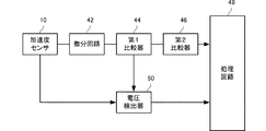
特許文献1の装置の構成を図1に示す。この落下検知装置は、加速度センサ10、その加速度検出信号を微分して微分信号を出力する微分回路42、微分信号が所定の第1のしきい値に達したか否かを判別する第1比較器44、微分信号が第1のしきい値より高い第2のしきい値に達したか否かを判別する第2比較器46、電圧検出器50および処理回路48を備えている。Conventionally,
The configuration of the device of
この図1に示した落下検知装置は、加速度センサ10の出力信号が予め定めた設定値に達して一定時間保たれている場合に、微分信号が第1のしきい値に達した時に第1処理状態と判定し、第2のしきい値に達した時に第2処理状態と判定することにより、例えば第1処理状態ではハードディスク装置の磁気ヘッドが例えば記録動作中であれば記録動作を一時停止させるような安全動作を制御し、第2処理状態と判断された場合に例えばハードディスク装置をさらに安全な状態に制御する。
The fall detection device shown in FIG. 1 is the first when the differential signal reaches the first threshold value when the output signal of the
特許文献2の落下検知装置は、加速度センサと落下判定処理部とを備え、その判定には加速度と加速度の微分値との両方を同時に用いるように構成されている。
ところが特許文献1の落下検知装置では、落下判定のために同時に2つのしきい値を用いる必要があるので判定処理が複雑となる。そのため、特にソフトウェアで判定を行う場合に、CPUの演算負荷が大きくなり、処理時間が長くなる等の問題が生じる。
However, in the drop detection device of
また、特許文献1では、落下状態または衝撃が加わった状態のそれぞれについて判定が行えるが、落下の開始が疑われる状態を検出すること(落下予測)ができず、落下に対する早期の対応処理ができないという問題がある。
Further, in
また、特許文献1では加速度を判定に用いているが、一般に加速度センサの加速度検出値にはオフセットを含んでいるため、加速度センサのオフセット調整が必要となる。
Moreover, although the acceleration is used for the determination in
また、例えば回転しながら落下するような場合に、その遠心力による加速度が加算されることになるので、加速度の検出値には回転による遠心力の影響を受けやすく、装置が回転しながら落下するような場合に的確な落下判定がなされないというおそれもある。 In addition, for example, in the case of falling while rotating, the acceleration due to the centrifugal force is added. Therefore, the detected value of the acceleration is easily affected by the centrifugal force due to the rotation, and the device falls while rotating. In such a case, there is a possibility that an accurate fall determination is not made.
特許文献2の落下検知装置でも、加速度と加速度の微分値の両方を同時に用いるため、判定処理が複雑であり、特許文献1の場合と同様の問題が生じる。また落下予測を行うこともできない。
Even in the drop detection device of
そこで、この発明の目的は、上述の問題を解消してソフトウェアで判定を行う場合の処理負荷を軽減して且つ落下予測も行えるようにした落下検知装置、それを備えた磁気ディスク装置および携帯電子機器を提供することにある。 SUMMARY OF THE INVENTION Accordingly, an object of the present invention is to provide a drop detection device that solves the above-described problems and reduces the processing load when performing determination by software and can also predict fall, a magnetic disk device including the drop detection device, and a portable electronic device. To provide equipment.
前記課題を解決するために、この発明は次のように構成する。
(1)加速度センサの出力信号を基に落下検知を行う落下検知装置であって、
加速度の絶対値の微分値を表す信号が、(定常状態から)所定の負のしきい値より負方向に下回るか、負の所定の範囲内に入る落下開始状態であるか否かを監視する落下開始監視手段と、
前記落下開始状態から所定時間内に前記加速度の絶対値を表す信号が所定のしきい値を下回るか、定常状態(重力加速度印加状態)より低い所定の範囲内に入る低重力状態への移行(遷移)期であるか否かを検出する低重力状態移行検出手段と、
前記低重力状態が所定時間以上継続する落下中状態を検出する落下中状態検出手段と、
を備える。In order to solve the above problems, the present invention is configured as follows.
(1) A fall detection device that detects fall based on an output signal of an acceleration sensor,
Monitors whether the signal representing the differential value of the absolute value of acceleration falls below the predetermined negative threshold (from the steady state) in the negative direction or is in the fall start state falling within the predetermined negative range. A drop start monitoring means;
Transition to a low-gravity state in which a signal representing the absolute value of the acceleration falls below a predetermined threshold value within a predetermined time from the fall start state or falls within a predetermined range lower than the steady state (gravity acceleration application state) ( A low-gravity state transition detecting means for detecting whether or not a transition) period;
A falling state detecting means for detecting a falling state in which the low gravity state continues for a predetermined time or more;
Is provided.
(2)加速度センサの出力信号を基に落下検知を行う落下検知装置であって、
加速度の微分値の絶対値を表す信号が、(定常状態から)所定のしきい値を超えるか、所定の範囲内に入る落下開始状態であるか否かを監視する落下開始監視手段と、
前記落下開始状態から所定時間内に前記加速度の絶対値を表す信号が所定のしきい値を下回るか、定常状態(重力加速度印加状態)より低い所定の範囲内に入る低重力状態への移行(遷移)期であるか否かを検出する低重力状態移行検出手段と、
前記低重力状態が所定時間以上継続する落下中状態を検出する落下中状態検出手段と、
を備える。(2) A drop detection device that detects a drop based on an output signal of an acceleration sensor,
A fall start monitoring means for monitoring whether the signal representing the absolute value of the differential value of acceleration exceeds a predetermined threshold value (from a steady state) or a fall start state that falls within a predetermined range;
Transition to a low-gravity state in which a signal representing the absolute value of the acceleration falls below a predetermined threshold value within a predetermined time from the fall start state or falls within a predetermined range lower than the steady state (gravity acceleration application state) ( A low-gravity state transition detecting means for detecting whether or not a transition) period;
A falling state detecting means for detecting a falling state in which the low gravity state continues for a predetermined time or more;
Is provided.
(3)加速度センサの出力信号を基に落下検知を行う落下検知装置であって、
加速度の絶対値の微分値を表す信号が、(定常状態から)所定の負のしきい値より負方向に下回るか、負の所定の範囲内に入る落下開始状態であるか否かを監視する落下開始監視手段と、
前記落下開始状態から所定時間内に前記加速度の絶対値の微分値を表す信号が所定のしきい値より0に近づく低重力状態への移行(遷移)期であるか否かを検出する低重力状態移行検出手段と、
前記低重力状態が所定時間以上継続する落下中状態を検出する落下中状態検出手段と、
を備える。(3) A fall detection device that performs fall detection based on an output signal of an acceleration sensor,
Monitors whether the signal representing the differential value of the absolute value of acceleration falls below the predetermined negative threshold (from the steady state) in the negative direction or is in the fall start state falling within the predetermined negative range. A drop start monitoring means;
Low gravity for detecting whether or not a signal representing the differential value of the absolute value of the acceleration within a predetermined time from the fall start state is a transition (transition) period to a low gravity state that approaches 0 from a predetermined threshold value State transition detection means;
A falling state detecting means for detecting a falling state in which the low gravity state continues for a predetermined time or more;
Is provided.
(4)加速度センサの出力信号を基に落下検知を行う落下検知装置であって、
加速度の微分値の絶対値を表す信号が、(定常状態から)所定の正のしきい値を超えるか、所定の範囲内に入る落下開始状態であるか否かを監視する落下開始監視手段と、
前記落下開始状態から所定時間内に前記加速度の微分値の絶対値を表す信号が所定のしきい値より0に近づく低重力状態への移行(遷移)期であるか否かを検出する低重力状態移行検出手段と、
前記低重力状態が所定時間以上継続する落下中状態を検出する落下中状態検出手段と、
を備える。(4) A drop detection device that detects a drop based on an output signal of an acceleration sensor,
Drop start monitoring means for monitoring whether a signal representing the absolute value of the differential value of acceleration exceeds a predetermined positive threshold value (from a steady state) or a fall start state that falls within a predetermined range; ,
Low gravity for detecting whether or not the signal representing the absolute value of the differential value of the acceleration within a predetermined time from the fall start state is in a transition (transition) period to a low gravity state that approaches 0 from a predetermined threshold value State transition detection means;
A falling state detecting means for detecting a falling state in which the low gravity state continues for a predetermined time or more;
Is provided.
(5)前記落下開始監視手段が前記落下開始状態を検出したとき、または前記低重力状態移行検出手段が前記低重力状態への移行を検出したとき、落下警告信号を出力する手段と、前記落下状態検出手段が前記落下状態を検出したとき落下検知信号を出力する手段とを備える。 (5) a means for outputting a fall warning signal when the fall start monitoring means detects the fall start state, or when the low gravity state transition detection means detects a transition to the low gravity state; Means for outputting a fall detection signal when the state detection means detects the fall state.
(6)前記落下検知装置を備えた磁気ディスク装置であって、磁気ディスクに対してデータの記録または読み出しを行うヘッドと、前記落下検知装置が前記落下開始状態、前記低重力状態、または前記落下中状態を検知したとき、前記ヘッドを退避領域に退避させるヘッド退避手段とを備える。 (6) A magnetic disk device including the drop detection device, wherein the head performs recording or reading of data on the magnetic disk, and the drop detection device is in the fall start state, the low gravity state, or the fall And a head retracting means for retracting the head to the retracting area when an intermediate state is detected.
(7)前記落下検知装置と、衝撃対策処理可能なデバイスとを備えた携帯電子機器であって、前記落下検知装置が前記落下開始状態、前記低重力状態、または前記落下中状態を検知したとき、前記デバイスに対して前記衝撃対策処理を施す衝撃対策処理手段とを備える。 (7) A portable electronic device including the fall detection device and a device capable of handling an impact, and when the fall detection device detects the fall start state, the low gravity state, or the falling state And impact countermeasure processing means for applying the impact countermeasure processing to the device.
この発明によれば次のような効果を奏する。
(1)請求項1〜4に係る発明によれば、落下開始監視手段が行う、加速度の絶対値の微分値を表す信号が所定の負のしきい値より負方向に下回るか負の所定範囲内に入る落下開始状態であるか否かの監視と、低重力状態移行検出手段が行う、落下開始状態から所定時間内に加速度の絶対値を表す信号が所定のしきい値を下回るか定常状態より低い所定の範囲内に入る低重力状態への移行期であるか否かの検出と、落下状態検出手段が行う、低重力状態の所定時間以上の継続を落下状態として検出する処理とは、この時間順序で順次行えばよいので、同時に複数のしきい値を基にする判定や同時に加速度と加速度の微分値を基にした判定を行う必要がなく、特にソフトウェアで判定を行う場合に、CPUの演算負荷が大きくなり、処理時間が長くなる等の問題が解消できる。According to the present invention, the following effects can be obtained.
(1) According to the first to fourth aspects of the present invention, the signal representing the differential value of the absolute value of acceleration performed by the drop start monitoring means is less than the predetermined negative threshold value in the negative direction or the negative predetermined range Monitoring whether or not it is in a fall start state that falls within, and a signal indicating the absolute value of the acceleration within a predetermined time from the fall start state performed by the low gravity state transition detection means falls below a predetermined threshold or is in a steady state The detection of whether or not it is a transition period to a low-gravity state that falls within a lower predetermined range, and the process of detecting a continuation of the low-gravity state for a predetermined time or more as a falling state, performed by the falling state detection means, Since it is only necessary to sequentially perform in this time order, it is not necessary to perform determination based on a plurality of threshold values at the same time or determination based on the differential value of acceleration and acceleration at the same time. Processing load increases, processing time Problems such as Kunar can be solved.
また、落下開始監視手段が落下開始状態であることを検出した段階または低重力状態移行検出手段が低重力状態への移行を検出した段階で、落下の開始が疑われるので、すなわち落下予測ができるので、最終的に落下状態の検知を確定するより早く落下に対する対応をとることができる。 Moreover, since the start of the fall is suspected when the fall start monitoring means detects the fall start state or when the low gravity state transition detection means detects the transition to the low gravity state, the fall prediction can be performed. Therefore, it is possible to take a response to the fall earlier than finally confirming the detection of the fall state.
(2)請求項3・請求項4に係る発明によれば、低重力状態移行検出手段と落下状態検出手段のいずれも、落下開始監視手段と同様に加速度の絶対値の微分値または微分値の絶対値を基にして判定を行うので、すなわち加速度の値を使用しないので、加速度検出のオフセット補正が不要となる。また、装置が回転しながら落下するような場合に、その遠心力による加速度が加速度の検出信号に加算されることになるが、回転速度が一定である場合、加速度の検出信号の微分値には影響を与えないので、回転の影響を受けることなく的確な落下検知を行える。
(2) According to the inventions according to
(3)落下開始監視手段が落下開始状態を検出した時または低重力状態移行検出手段が低重力状態への移行を検出した時に落下警告信号を出力することによって落下予測に対する処理が可能となる。また落下状態検出手段が落下状態を検出した時に落下検知信号を出力するので、2段階の状態に応じた落下に対する処理を行うことができる。 (3) When the fall start monitoring means detects the fall start state or when the low gravity state transition detection means detects the transition to the low gravity state, the process for the fall prediction can be performed by outputting a fall warning signal. In addition, since the fall detection signal is output when the fall state detection means detects the fall state, it is possible to perform processing for the fall according to the two-stage state.
(4)このような落下検知装置を備え、落下を検知した際にヘッドを退避領域に退避させるように構成したことにより、その磁気ディスク装置を保護することができ、且つ誤検知が少ないので使用中の磁気ディスク装置の応答速度の低下の問題が解消できる。 (4) Since such a fall detection device is provided and the head is retracted to the retreat area when a fall is detected, the magnetic disk device can be protected and used because there are few false detections. The problem of a decrease in response speed of the magnetic disk device inside can be solved.
(5)落下開始状態または低重力状態で落下に備える処理を行うことができ、また落下中状態を検知した時に落下に対する処理を行うことができるので、衝撃対策処理可能なデバイスを有効に制御して携帯電子機器の安全性が高められる。 (5) Because it is possible to prepare for a fall in a fall start state or low gravity state, and to perform a drop process when a falling state is detected, it is possible to effectively control devices that can handle impact countermeasures. This increases the safety of portable electronic devices.
60−加速度センサ
100−落下検知装置60-acceleration sensor 100-fall detection device
《第1の実施形態》
図2は第1の実施形態に係る落下検知装置の構成を示すブロック図である。落下検知装置100は、加速度を検出して加速度に対応したアナログ電圧信号を出力する加速度センサ60、加速度センサ60の出力電圧をディジタルデータに変換するA/Dコンバータ72、およびA/Dコンバータ72の出力データを基にして落下検知を行い、検知結果を外部(ホスト装置)へ出力する制御部74から構成している。<< First Embodiment >>
FIG. 2 is a block diagram showing the configuration of the fall detection device according to the first embodiment. The
落下方向がどの向きであるか不定である場合にも、その落下を検知するために、3次元方向の加速度を検出して、それらを基にして落下検知を行う。この場合、具体的には、図2において加速度センサ60は互いに直交するX軸方向,Y軸方向およびZ軸方向の加速度をそれぞれ検出する3つの加速度センサで構成し、A/Dコンバータ72は各加速度センサの出力電圧をそれぞれディジタルデータに変換する。さらに制御部74は、後述する、加速度の絶対値を求める際に、各軸方向の加速度をax,ay,azで表すと、ベクトルである加速度aの絶対値|a|は、|a|=√(ax2 +ay2 +az2 )の演算によって求める。Even when the falling direction is uncertain, in order to detect the falling, the acceleration in the three-dimensional direction is detected, and the falling is detected based on the detected acceleration. In this case, specifically, in FIG. 2, the
なお、所定の一方向の加速度のみを求めるだけでよい場合には、上記加速度aの絶対値|a|は、上記一方向の加速度a自体を用いればよい。 If only the acceleration in one predetermined direction needs to be obtained, the absolute value | a | of the acceleration a may be the acceleration a in one direction.
加速度センサとしては、圧電型、ピエゾ抵抗型、容量型など各種形式の加速度センサを用いることができる。 As the acceleration sensor, various types of acceleration sensors such as a piezoelectric type, a piezoresistive type, and a capacitive type can be used.
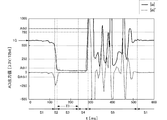
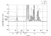
図3は前記落下検知装置100が落下の前後で受ける加速度と加速度の微分値の時間経過の例を示している。ここで縦軸は加速度の絶対値|a|およびその微分値|a|′であり、加速度の絶対値|a|についてはA/Dコンバータ72の出力値、その微分値|a|′は、単位時間での加速度の絶対値|a|の差分値である。また、横軸は経過時間t[ms]である。
FIG. 3 shows an example of the time lapse of the acceleration received by the
第1段階S1はまだ落下を開始していない「定常状態」である。したがって加速度は重力加速度(=1G)であり、この時のA/Dコンバータの出力値は約600である。また加速度の絶対値|a|はほぼ一定であるので、その微分値|a|′はほぼ0である。その後のある時点で落下が開始すると、加速度の絶対値|a|は急激に低下し、その微分値|a|′は負方向に低下する。 The first stage S1 is a “steady state” in which the drop has not yet started. Therefore, the acceleration is gravitational acceleration (= 1G), and the output value of the A / D converter at this time is about 600. Further, since the absolute value | a | of acceleration is almost constant, its differential value | a | 'is almost zero. When the fall starts at a certain time thereafter, the absolute value | a | of the acceleration decreases rapidly, and its differential value | a | 'decreases in the negative direction.
微分値|a|′がしきい値DAth1を下回ったとき、第2段階S2「落下開始状態」になったものと見なす。 When the differential value | a | ′ falls below the threshold value DAth1, it is considered that the second stage S2 “falling start state” has been entered.
その後、落下検知装置は自由運動により低重力状態(無重力状態)となり、加速度の絶対値|a|はほぼ0となる。 Thereafter, the fall detection device is brought into a low gravity state (non-gravity state) by free movement, and the absolute value | a |
加速度の絶対値|a|がしきい値Ath1を下回ったとき、第3段階S3「低重力状態」になったものと見なす。その後も加速度の絶対値|a|は低下するが、加速度センサ60の出力にオフセットが存在する場合には、図3に示すように加速度の絶対値|a|は完全に0とはならない。
When the absolute value | a | of the acceleration falls below the threshold value Ath1, it is considered that the third stage S3 is in the “low gravity state”. After that, the absolute value | a | of the acceleration decreases. However, if there is an offset in the output of the
この低重力状態が一定時間T3経過した時点で「落下中状態」になったものと見なす。第4段階S4はその「落下中状態」である。 It is considered that the low gravity state has entered the “falling state” when a certain time T3 has elapsed. The fourth stage S4 is the “falling state”.
その後、落下検知装置は(それを搭載した電子機器は)床等に衝突して、落下検知装置の加速度の絶対値|a|は急激に上昇する。またバウンド等を繰り返すことによって加速度の絶対値|a|は大きく変動する。図中の第5段階S5がこの「落下衝撃状態」を表している。 Thereafter, the fall detection device (the electronic device on which the fall detection device is mounted) collides with the floor or the like, and the absolute value | a | of the fall detection device increases rapidly. Further, the absolute value | a | The fifth stage S5 in the figure represents this “drop impact state”.
その後、バウンドが収まると、または人が電子機器を持ち上げて加速度が安定すると第1段階S1「定常状態」に戻る。 Thereafter, when the bounce is settled or when the person lifts the electronic device and the acceleration is stabilized, the first stage S1 returns to the “steady state”.
なお、図3に示した例ではクッション材の上に落下させたため、第5段階S5の時間が比較的長く現れている。 In addition, in the example shown in FIG. 3, since it was dropped on the cushion material, the time of 5th step S5 appears comparatively long.
図2に示した制御部74は図3に示したA/Dコンバータ72の出力値を基にして落下検知を行う。図4・図5はそのための処理手順をフローチャートとして表したものである。
The
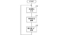
図4は加速度センサの出力から落下検知のための基になるデータを生成する処理手順である。まず、A/Dコンバータ72の出力値(加速度の値)を入力する(n10)。続いてその絶対値|a|を演算する(n11)。さらにその微分値|a|′を演算する(n12)。これは前回の加速度の絶対値|a|と今回の加速度の絶対値|a|との差分をとること等によって求める。この図4に示した処理は、サンプリング周期毎に繰り返し行う。
FIG. 4 shows a processing procedure for generating data to be a basis for drop detection from the output of the acceleration sensor. First, the output value (acceleration value) of the A /
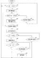
図5は、前記加速度の絶対値とその微分値を基にして図3に示した第1段階S1から第5段階S5の状態を検知するとともに所定の段階で外部へ各種信号を出力するための手順を示すフローチャートである。 FIG. 5 is a diagram for detecting the state of the first step S1 to the fifth step S5 shown in FIG. 3 based on the absolute value of the acceleration and its differential value and outputting various signals to the outside at a predetermined step. It is a flowchart which shows a procedure.
まず加速度の絶対値の微分値|a|′がしきい値DAth1を下回るか否かを判定する(n20)。この条件が成立すると「落下開始信号」を外部(ホスト装置)へ出力する(n20→n21)。この落下開始信号はホスト装置側で落下警告信号として扱われ、例えばハードディスクドライブ装置であれば、ヘッド退避に備えた読み書き完了制御等を行う。 First, it is determined whether or not the differential value | a | 'of the absolute value of acceleration is below the threshold value DAth1 (n20). When this condition is satisfied, a “drop start signal” is output to the outside (host device) (n20 → n21). This drop start signal is handled as a drop warning signal on the host device side. For example, in the case of a hard disk drive device, read / write completion control for head retraction is performed.
上記ステップn20の繰り返しが図3に示した第1段階S1「定常状態」である。落下開始信号を出力した状態で図3に示した第2段階S2「落下開始状態」となる。
なお、この第2段階への移行は、加速度の絶対値の微分値|a|′が定常状態より低い所定範囲内に入るか否かによって判定するようにしてもよい。The repetition of step n20 is the first stage S1 “steady state” shown in FIG. When the drop start signal is output, the second stage S2 “drop start state” shown in FIG. 3 is entered.
The transition to the second stage may be determined based on whether or not the differential value | a | 'of the absolute value of acceleration falls within a predetermined range lower than the steady state.
その後、加速度の絶対値|a|がしきい値Ath1を下回るのを待つ(n21→n22→n23→n22→・・・)。所定時間T2が経過しても(例えば50ms経過しても加速度の絶対値|a|がしきい値Ath1より下回らなければ電子機器の単なる移動や取扱いによる一時的な加速度低下であるものと見なして前記落下警告を解除する(n23→n24→n20)。これにより第1段階S1「定常状態」に戻る。 Thereafter, it waits for the absolute value of acceleration | a | to fall below the threshold value Ath1 (n21 → n22 → n23 → n22 →...). Even if the predetermined time T2 elapses (for example, even if 50 ms elapses), if the absolute value of acceleration | a | does not fall below the threshold value Ath1, it is regarded as a temporary decrease in acceleration due to mere movement or handling of the electronic device. The drop warning is canceled (n23 → n24 → n20), thereby returning to the first stage S1 “steady state”.
前記所定時間T2以内に加速度の絶対値がAth1未満となれば「低重力状態信号」を出力する(n22→n25)。
なお、この第3段階への移行は、加速度の絶対値|a|が定常状態より低い所定範囲内に入るか否かによって判定するようにしてもよい。If the absolute value of acceleration is less than Ath1 within the predetermined time T2, a “low-gravity state signal” is output (n22 → n25).
The transition to the third stage may be determined based on whether or not the absolute value | a | of acceleration falls within a predetermined range lower than the steady state.
上記低重力状態が所定時間T3継続すれば「落下中信号」を出力する(n26→n27)。これで図3に示した第4段階S4「落下中状態」となる。 If the low gravity state continues for a predetermined time T3, a “falling signal” is output (n26 → n27). Thus, the fourth stage S4 “falling state” shown in FIG. 3 is reached.
その後、加速度の絶対値|a|がしきい値Ath2を超えた時、「衝撃信号」を出力する(n28→n30)。これにより図3に示した第5段階S5「落下衝撃状態」となる。 Thereafter, when the absolute value | a | of the acceleration exceeds the threshold value Ath2, an “impact signal” is output (n28 → n30). Thus, the fifth stage S5 “drop impact state” shown in FIG. 3 is established.
もし所定時間T4が経過しても加速度の絶対値|a|がしきい値Ath2を超えなければ衝撃が未然に回避されたものとして定常状態に戻る(n28→n29→n20)。 If the absolute value | a | of the acceleration does not exceed the threshold value Ath2 even if the predetermined time T4 has elapsed, it is assumed that the impact has been avoided, and the steady state is restored (n28 → n29 → n20).
前記衝撃信号を出力した後、加速度の絶対値が重力加速度(=1G)にほぼ等しくなれば定常状態に戻る(n31→n20)。 After outputting the impact signal, if the absolute value of acceleration is substantially equal to gravitational acceleration (= 1G), the steady state is restored (n31 → n20).
また所定時間経過してもほぼ重力加速度にならなければ、例えば落下検知装置が衝撃により異常の状態となったものと見なす異常処理を行う(n31→n32→n33)。 Further, if the gravitational acceleration does not substantially occur even after a predetermined time has elapsed, for example, an abnormality process is performed in which it is considered that the fall detection device has become abnormal due to an impact (n31 → n32 → n33).
このように図3に示した各段階S1〜S5のいずれの段階でも加速度の絶対値|a|とその微分値|a|′のいずれか一方のみを用いて判定を行うので、CPUの演算負荷が小さくなり、必要な演算に要する時間(単位時間)を短くできるので、サンプリング周期を短くでき、その結果、より応答性の高い落下検知装置が構成できる。 As described above, since the determination is made using only one of the absolute value | a | and the differential value | a | 'of the acceleration at any of the steps S1 to S5 shown in FIG. Since the time required for computation (unit time) can be shortened, the sampling cycle can be shortened, and as a result, a drop detection device with higher response can be configured.
《第2の実施形態》
第1の実施形態では加速度の絶対値とその微分値の両方を基にして(但しタイミングとしては同時に用いることなく)各状態の判定を行ったが、この第2の実施形態では加速度の絶対値の微分値のみを基にして同様の判定を行う。落下検知装置全体の構成は第1の実施形態で図2に示したものと同様である。また加速度の絶対値とその微分値の演算については図4に示した処理手順と同様である。<< Second Embodiment >>
In the first embodiment, each state is determined on the basis of both the absolute value of acceleration and its differential value (but not used at the same time). In the second embodiment, the absolute value of acceleration is used. The same determination is made based only on the differential value of. The overall configuration of the fall detection device is the same as that shown in FIG. 2 in the first embodiment. The calculation of the absolute value of acceleration and its differential value is the same as the processing procedure shown in FIG.
図6は第2の実施形態に係る落下検知装置の落下の前後で受ける加速度と加速度の微分値の時間経過の例を示している。ここで縦軸は加速度の絶対値|a|およびその微分値|a|′であり、加速度の絶対値|a|についてはA/Dコンバータ72の出力値、その微分値|a|′は、単位時間での加速度の絶対値|a|の差分値である。また、横軸は経過時間t[ms]である。但し、図6では加速度の絶対値|a|を表しているがこの値を何らかのしきい値と比較することはない。
FIG. 6 shows an example of the time elapsed of the acceleration received before and after the fall of the fall detection device according to the second embodiment and the differential value of the acceleration. Here, the vertical axis represents the absolute value of acceleration | a | and its differential value | a | '. Regarding the absolute value of acceleration | a |, the output value of the A /
図6において加速度の絶対値の微分値|a|′がしきい値DAth1を下回ったとき、第2段階S2「落下開始状態」見なす。
なお、この第2段階への移行は、加速度の絶対値の微分値|a|′が定常状態より低い所定範囲内に入るか否かによって判定するようにしてもよい。In FIG. 6, when the differential value | a | 'of the absolute value of acceleration falls below the threshold value DAth1, the second stage S2 “falling start state” is regarded.
The transition to the second stage may be determined based on whether or not the differential value | a | 'of the absolute value of acceleration falls within a predetermined range lower than the steady state.
その後、|a|′がしきい値DAth2〜DAth4の範囲内に入ったとき、第3段階S3「低重力状態」になったものと見なす。このように|a|′が単にしきい値DAth2を超えたか否かを判定するのではなく、所定範囲内に入ったか否かを判定することによって、装置の振動を誤って落下と判定することが無い。 Thereafter, when | a | ′ falls within the range of the threshold values DAth2 to DAth4, it is considered that the third stage S3 is in the “low-gravity state”. In this way, it is not determined whether or not | a | 'simply exceeds the threshold value DAth2, but by determining whether or not it falls within a predetermined range, it is determined that the vibration of the device is erroneously dropped. There is no.
この低重力状態が一定時間T3経過した時点で「落下中状態」になったものと見なす。第4段階S4はその「落下中状態」である。 It is considered that the low gravity state has entered the “falling state” when a certain time T3 has elapsed. The fourth stage S4 is the “falling state”.
その後、加速度の絶対値の微分値|a|′がしきい値DAth3を超えたとき、第5段階S5「落下衝撃状態」になったものと見なす。 Thereafter, when the differential value | a | ′ of the absolute value of acceleration exceeds the threshold value DAth3, it is considered that the fifth stage S5 “drop impact state” has been entered.
さらにその後、|a|′がほぼ0となったとき、第1段階S1「定常状態」になったものと見なす。 After that, when | a | ′ becomes almost zero, it is considered that the first stage S1 is “steady state”.
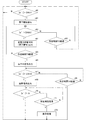
図7は前記加速度の絶対値の微分値|a|′を基にして各段階の判定を行う手順を示すフローチャートである。
まず加速度の絶対値の微分値|a|′がしきい値DAth1を下回るか否かを判定する(n40)。この条件が成立すると「落下開始信号」を外部へ出力する(n41)。FIG. 7 is a flow chart showing a procedure for determining each stage based on the differential value | a | 'of the absolute value of the acceleration.
First, it is determined whether or not the differential value | a | 'of the absolute value of acceleration falls below the threshold value DAth1 (n40). When this condition is satisfied, a “falling start signal” is output to the outside (n41).
上記ステップn40の繰り返しが図6に示した第1段階S1「定常状態」である。落下開始信号を出力した状態で図6に示した第2段階S2「落下開始状態」となる。 The repetition of step n40 is the first stage S1 “steady state” shown in FIG. In a state where the drop start signal is output, the second stage S2 “drop start state” shown in FIG. 6 is entered.
その後、加速度の絶対値の微分値|a|′がしきい値DAth2〜DAth4の範囲内に入るのを待つ(n42→n43→n42→・・・)。所定時間T2が経過しても(例えば50ms経過しても|a|′がしきい値DAth2〜DAth4の範囲内に入らなければ電子機器の単なる移動や取扱いによる一時的な加速度低下であるものと見なして「定常状態」に戻る(n43→n40)。 After that, it waits for the differential value | a | 'of the absolute value of acceleration to fall within the range of threshold values DAth2 to DAth4 (n42 → n43 → n42 →...). Even if the predetermined time T2 elapses (for example, even if 50 ms elapses), if | a | It considers and returns to a "steady state" (n43-> n40).
前記所定時間T2以内に|a|′がDAth2を超えたなら「低重力状態信号」を出力する(n44)。この状態が所定時間T3継続すれば「落下中信号」を出力する(n45→n46)。これで図6に示した第4段階S4「落下中状態」となる。 If | a | ′ exceeds DAth2 within the predetermined time T2, a “low-gravity state signal” is output (n44). If this state continues for a predetermined time T3, a “falling signal” is output (n45 → n46). Thus, the fourth stage S4 “falling state” shown in FIG. 6 is reached.
その後、加速度の絶対値の微分値|a|′がしきい値DAth3を超えた時、「衝撃信号」を出力する(n47→n49)。これにより図6に示した第5段階S5「落下衝撃状態」となる。 Thereafter, when the differential value | a | ′ of the absolute value of acceleration exceeds the threshold value DAth3, an “impact signal” is output (n47 → n49). As a result, the fifth stage S5 “drop impact state” shown in FIG. 6 is entered.
もし所定時間T4が経過しても|a|′がしきい値DAth3を超えなければ衝撃が未然に回避されたものとして定常状態に戻る(n48→n40)。 If | a | ′ does not exceed the threshold value DAth3 even if the predetermined time T4 elapses, it is assumed that the impact has been avoided, and the steady state is restored (n48 → n40).
前記衝撃信号を出力した後、加速度の絶対値の微分値|a|′がほぼ0になれば定常状態に戻る(n50→n40)。 After the impact signal is output, the steady state is restored (n50 → n40) when the differential value | a | 'of the absolute value of acceleration becomes substantially zero.
また所定時間経過しても|a|′がほぼ0にならなければ、例えば落下検知装置が衝撃により異常の状態となったものと見なす異常処理を行う(n51→n52)。 If | a | ′ does not become substantially zero even after a predetermined time has elapsed, for example, an abnormality process is performed in which it is considered that the drop detection device has become abnormal due to an impact (n51 → n52).
このようにして加速度の絶対値の微分値|a|′のみを用いて各段階の判定を行い、必要な信号を出力する。 In this way, the determination at each stage is performed using only the differential value | a | 'of the absolute value of acceleration, and a necessary signal is output.
《第3の実施形態》
第2の実施形態では加速度の絶対値の微分値を基にして各状態の判定を行ったが、第3の実施形態では加速度の微分値の絶対値を基にして同様の判定を行う。落下検知装置全体の構成は第1の実施形態で図2に示したものと同様である。<< Third Embodiment >>
In the second embodiment, each state is determined based on the differential value of the absolute value of acceleration. In the third embodiment, the same determination is performed based on the absolute value of the differential value of acceleration. The overall configuration of the fall detection device is the same as that shown in FIG. 2 in the first embodiment.
加速度の微分値の絶対値は次のようにして求める。まず、A/Dコンバータ72の出力値(加速度の値)を入力し、その微分値a′を演算する。これは前回の加速度と今回の加速度aとの差分をとること等によって求める。そして、各軸方向の加速度の微分値をax′,ay′,az′で表すと、|a′|=√(ax′2 +ay′2 +az′2 )の演算によって加速度の微分値の絶対値|a′|を求める。この処理をサンプリング周期毎に繰り返し行う。The absolute value of the differential value of acceleration is obtained as follows. First, the output value (acceleration value) of the A /
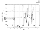
図8は、第3の実施形態に係る落下検知装置の加速度センサの検出した加速度の絶対値および加速度の微分値の絶対値の変化の例、および加速度の微分値の絶対値を基にして定めた第1段階S1〜第5段階S5の各段階の遷移状態を示す図である。 FIG. 8 is determined based on an example of changes in the absolute value of the acceleration and the differential value of the acceleration detected by the acceleration sensor of the fall detection device according to the third embodiment, and the absolute value of the differential value of the acceleration. It is a figure which shows the transition state of each step of 1st step S1-5th step S5.
ここで縦軸は加速度の絶対値|a|および加速度の微分値の絶対値|a′|である。また、横軸は経過時間t[ms]である。但し、図8では加速度の絶対値|a|を表しているがこの値を何らかのしきい値と比較することはない。 Here, the vertical axis represents the absolute value | a | of acceleration and the absolute value | a '| of differential value of acceleration. The horizontal axis represents the elapsed time t [ms]. Although FIG. 8 shows the absolute value | a | of acceleration, this value is not compared with any threshold value.
図8において加速度の微分値の絶対値|a′|がしきい値DAth1を超えたとき、第2段階S2「落下開始状態」見なす。この第2段階への移行は、加速度の微分値の絶対値|a′|が定常状態より高い所定範囲内に入るか否かによって判定するようにしてもよい。 In FIG. 8, when the absolute value | a ′ | of the differential value of acceleration exceeds the threshold value DAth1, the second stage S2 “falling start state” is regarded. The transition to the second stage may be determined based on whether or not the absolute value | a ′ | of the differential value of acceleration falls within a predetermined range higher than the steady state.
その後、|a′|がしきい値DAth2を下回ったとき、第3段階S3「低重力状態」になったものと見なす。この第2段階への移行は、加速度の微分値の絶対値|a′|が所定範囲内に入るか否かによって判定するようにしてもよい。 Thereafter, when | a ′ | falls below the threshold value DAth2, it is considered that the third stage S3 has entered the “low-gravity state”. The transition to the second stage may be determined based on whether or not the absolute value | a '| of the differential value of acceleration falls within a predetermined range.
このように|a′|としきい値との比較を所定範囲内に入ったか否かを判定すれば、装置の振動を誤って落下と判定することが無くなる。 Thus, if it is determined whether or not the comparison between | a ′ | and the threshold value is within a predetermined range, it is not possible to erroneously determine that the vibration of the apparatus is falling.
この低重力状態が一定時間T3経過した時点で「落下中状態」になったものと見なす。第4段階S4はその「落下中状態」である。 It is considered that the low gravity state has entered the “falling state” when a certain time T3 has elapsed. The fourth stage S4 is the “falling state”.
その後、加速度の微分値の絶対値|a′|がしきい値DAth3を超えたとき、第5段階S5「落下衝撃状態」になったものと見なす。 Thereafter, when the absolute value | a ′ | of the differential value of acceleration exceeds the threshold value DAth3, it is considered that the fifth stage S5 “drop impact state” has been reached.
さらにその後、|a′|がほぼ0となったとき、第1段階S1「定常状態」になったものと見なす。 Thereafter, when | a ′ | becomes almost zero, it is considered that the first stage S1 “steady state” has been reached.
図9は第3の実施形態に係る落下検知装置の、加速度の微分値の絶対値を用いて各段階の判定を行う手順を示すフローチャートである。 FIG. 9 is a flowchart illustrating a procedure for performing determination at each stage using the absolute value of the differential value of acceleration in the fall detection device according to the third embodiment.
まず加速度の微分値の絶対値|a′|がしきい値DAth1を超えるか否かを判定する(n60)。この条件が成立すると「落下開始信号」を外部へ出力する(n61)。 First, it is determined whether or not the absolute value | a '| of the differential value of acceleration exceeds the threshold value DAth1 (n60). When this condition is satisfied, a “fall start signal” is output to the outside (n61).
上記ステップn60の繰り返しが図8に示した第1段階S1「定常状態」である。落下開始信号を出力した状態で図6に示した第2段階S2「落下開始状態」となる。 The repetition of step n60 is the first stage S1 “steady state” shown in FIG. In a state where the drop start signal is output, the second stage S2 “drop start state” shown in FIG. 6 is entered.
その後、加速度の微分値の絶対値|a′|がしきい値DAth2を下回るのを待つ(n62→n63→n62→・・・)。所定時間T2が経過しても(例えば50ms経過しても|a′|がしきい値DAth2を下回らなければ電子機器の単なる移動や取扱いによる一時的な加速度低下であるものと見なして「定常状態」に戻る(n63→n60)。 Thereafter, it waits for the absolute value | a ′ | of the differential value of acceleration to fall below the threshold value DAth2 (n62 → n63 → n62 →...). Even if the predetermined time T2 elapses (for example, even if 50 ms elapses), if | a ′ | does not fall below the threshold value DAth2, it is considered that the electronic device is simply moved and handled and the acceleration is temporarily reduced. ”(N63 → n60).
前記所定時間T2以内に|a′|がDAth2を下回ったなら「低重力状態信号」を出力する(n64)。この状態が所定時間T3継続すれば「落下中信号」を出力する(n65→n66)。これで図8に示した第4段階S4「落下中状態」となる。 If | a ′ | falls below DAth2 within the predetermined time T2, a “low-gravity state signal” is output (n64). If this state continues for a predetermined time T3, a “falling signal” is output (n65 → n66). Thus, the fourth stage S4 “falling state” shown in FIG. 8 is reached.
その後、加速度の微分値の絶対値|a′|がしきい値DAth3を超えた時、「衝撃信号」を出力する(n67→n69)。これにより図8に示した第5段階S5「落下衝撃状態」となる。 Thereafter, when the absolute value | a ′ | of the differential value of acceleration exceeds the threshold value DAth3, an “impact signal” is output (n67 → n69). As a result, the fifth stage S5 "drop impact state" shown in FIG. 8 is entered.
もし所定時間T4が経過しても|a′|がしきい値DAth3を超えなければ衝撃が未然に回避されたものとして定常状態に戻る(n68→n60)。 If | a ′ | does not exceed the threshold value DAth3 even if the predetermined time T4 has elapsed, it is assumed that the impact has been avoided, and the steady state is restored (n68 → n60).
前記衝撃信号を出力した後、加速度の微分値の絶対値|a′|がほぼ0になれば定常状態に戻る(n70→n60)。 After outputting the impact signal, when the absolute value | a '| of the differential value of acceleration becomes almost zero, the steady state is restored (n70 → n60).
また所定時間経過しても|a′|がほぼ0にならなければ、例えば落下検知装置が衝撃により異常の状態となったものと見なす異常処理を行う(n71→n72)。 If | a ′ | does not become substantially zero even after a predetermined time has elapsed, for example, an abnormality process is performed in which it is considered that the drop detection device has become abnormal due to an impact (n71 → n72).
このようにして加速度の微分値の絶対値|a′|のみを用いて各段階の判定を行い、必要な信号を出力する。 In this way, the determination at each stage is performed using only the absolute value | a ′ | of the differential value of acceleration, and a necessary signal is output.
このように、第3の実施形態では第2の実施形態の「加速度の絶対値の微分値」を「加速度の微分値の絶対値」に置き換えるとともに、それに応じたしきい値との比較を行うようにしたが、同様にして第1の実施形態で示した「加速度の絶対値の微分値」を「加速度の微分値の絶対値」に置き換えてもよい。その場合には、図5に示したステップn20の判定を、「|a′|>DAth1」の判定に置換すればよい。 As described above, in the third embodiment, the “differential value of the absolute value of acceleration” in the second embodiment is replaced with “the absolute value of the differential value of acceleration”, and the comparison with the threshold value is performed accordingly. However, the “differential value of the absolute value of acceleration” shown in the first embodiment may be similarly replaced with “the absolute value of the differential value of acceleration”. In that case, the determination in step n20 shown in FIG. 5 may be replaced with the determination of “| a ′ |> DAth1”.
《第4の実施形態》
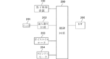
図10はハードディスクドライブ装置等の磁気ディスク装置の構成を示すブロック図である。ここで、読み書き回路202はヘッド201を用いて磁気ディスク上のトラックに、書き込まれているデータの読み取りまたは書き込みを行う。制御回路200は読み書き回路202を介してデータの読み書き制御を行い、この読み書きデータを、インタフェース205を介してホスト装置との間で通信する。また制御回路200はスピンドルモータ204を制御し、ボイスコイルモータ203を制御する。また制御回路200は落下検知装置100による落下検知信号を読み取って、落下状態の時、ボイスコイルモータ203を制御してヘッド201を退避領域に退避させる。これにより、たとえば、ハードディスク装置が搭載された携帯機器を落下させた際に、携帯機器が床や地面に衝突するまでにヘッドを磁気ディスクの領域から退避領域へ退避させるので、ヘッド201の磁気ディスクの記録面に対する接触による損傷が防止できる。<< Fourth Embodiment >>
FIG. 10 is a block diagram showing the configuration of a magnetic disk device such as a hard disk drive device. Here, the read /
《第5の実施形態》
図11は、ハードディスクドライブ装置を内蔵したノートパソコンや音楽・映像再生装置等の携帯電子機器の構成を示すブロック図である。ここで落下検知装置100の構成は第1・第2の実施形態で示したとおりである。デバイス301は落下時の衝突による衝撃から保護する必要のあるデバイスであり、且つそのための対策処理可能なデバイスである。例えばハードディスクドライブ装置である。制御回路300は落下検知装置100の出力信号を基にしてデバイス301を制御する。例えば落下検知装置100から落下警告信号(落下開始信号または低い重力状態信号)を受け取ったなら、デバイス301に対して落下時の衝撃に備えた予備的な第1段階の制御を行う。また落下中状態を表す信号(落下中信号)を受け取ったなら、デバイス301に対して落下時の衝撃に備えた第2段階の制御を行う。<< Fifth Embodiment >>
FIG. 11 is a block diagram showing the configuration of a portable electronic device such as a notebook computer or a music / video playback device with a built-in hard disk drive device. Here, the configuration of the
Claims (7)
加速度の絶対値の微分値を表す信号が、所定の負のしきい値より負方向に下回るか、負の所定の範囲内に入る落下開始状態であるか否かを監視する落下開始監視手段と、
前記落下開始状態から所定時間内に前記加速度の絶対値を表す信号が所定のしきい値を下回るか、定常状態より低い所定の範囲内に入る低重力状態への移行期であるか否かを検出する低重力状態移行検出手段と、
前記低重力状態が所定時間以上継続する落下中状態を検出する落下中状態検出手段と、
を備える落下検知装置。A fall detection device that performs fall detection based on an output signal of an acceleration sensor,
Fall start monitoring means for monitoring whether or not a signal representing the differential value of the absolute value of acceleration falls in a negative direction below a predetermined negative threshold value or falls within a predetermined negative range. ,
Whether the signal representing the absolute value of the acceleration falls below a predetermined threshold value within a predetermined time from the falling start state, or is a transition period to a low gravity state that falls within a predetermined range lower than the steady state. Low gravity state transition detection means for detecting;
A falling state detecting means for detecting a falling state in which the low gravity state continues for a predetermined time or more;
A fall detection device comprising:
加速度の微分値の絶対値を表す信号が、所定のしきい値を超えるか、所定の範囲内に入る落下開始状態であるか否かを監視する落下開始監視手段と、
前記落下開始状態から所定時間内に前記加速度の絶対値を表す信号が所定のしきい値を下回るか、定常状態より低い所定の範囲内に入る低重力状態への移行期であるか否かを検出する低重力状態移行検出手段と、
前記低重力状態が所定時間以上継続する落下中状態を検出する落下中状態検出手段と、
を備える落下検知装置。A fall detection device that performs fall detection based on an output signal of an acceleration sensor,
A drop start monitoring means for monitoring whether or not the signal representing the absolute value of the differential value of acceleration exceeds a predetermined threshold value or a fall start state that falls within a predetermined range;
Whether the signal representing the absolute value of the acceleration falls below a predetermined threshold value within a predetermined time from the falling start state, or is a transition period to a low gravity state that falls within a predetermined range lower than the steady state. Low gravity state transition detection means for detecting;
A falling state detecting means for detecting a falling state in which the low gravity state continues for a predetermined time or more;
A fall detection device comprising:
加速度の絶対値の微分値を表す信号が、所定の負のしきい値より負方向に下回るか、負の所定の範囲内に入る落下開始状態であるか否かを監視する落下開始監視手段と、
前記落下開始状態から所定時間内に前記加速度の絶対値の微分値を表す信号が所定のしきい値より0に近づく低重力状態への移行期であるか否かを検出する低重力状態移行検出手段と、
前記低重力状態が所定時間以上継続する落下中状態を検出する落下中状態検出手段と、
を備える落下検知装置。A fall detection device that performs fall detection based on an output signal of an acceleration sensor,
Fall start monitoring means for monitoring whether or not a signal representing the differential value of the absolute value of acceleration falls in a negative direction below a predetermined negative threshold value or falls within a predetermined negative range. ,
Low-gravity state transition detection for detecting whether or not the signal representing the differential value of the absolute value of the acceleration is within the transition period to the low-gravity state approaching 0 from a predetermined threshold value within a predetermined time from the fall start state Means,
A falling state detecting means for detecting a falling state in which the low gravity state continues for a predetermined time or more;
A fall detection device comprising:
加速度の微分値の絶対値を表す信号が、所定のしきい値を超えるか、所定の範囲内に入る落下開始状態であるか否かを監視する落下開始監視手段と、
前記落下開始状態から所定時間内に前記加速度の微分値の絶対値を表す信号が所定のしきい値より0に近づく低重力状態への移行期であるか否かを検出する低重力状態移行検出手段と、
前記低重力状態が所定時間以上継続する落下中状態を検出する落下中状態検出手段と、
を備える落下検知装置。A fall detection device that performs fall detection based on an output signal of an acceleration sensor,
A drop start monitoring means for monitoring whether or not the signal representing the absolute value of the differential value of acceleration exceeds a predetermined threshold value or a fall start state that falls within a predetermined range;
Low-gravity state transition detection for detecting whether or not a signal representing the absolute value of the differential value of the acceleration within a predetermined time from the fall start state is a transition period to a low-gravity state that approaches 0 from a predetermined threshold value Means,
A falling state detecting means for detecting a falling state in which the low gravity state continues for a predetermined time or more;
A fall detection device comprising:
Applications Claiming Priority (3)
| Application Number | Priority Date | Filing Date | Title |
|---|---|---|---|
| JP2007149053 | 2007-06-05 | ||
| JP2007149053 | 2007-06-05 | ||
| PCT/JP2008/059546 WO2008149693A1 (en) | 2007-06-05 | 2008-05-23 | Drop detector, magnetic disc drive and portable electronic apparatus |
Publications (1)
| Publication Number | Publication Date |
|---|---|
| JPWO2008149693A1 true JPWO2008149693A1 (en) | 2010-08-26 |
Family
ID=40093517
Family Applications (1)
| Application Number | Title | Priority Date | Filing Date |
|---|---|---|---|
| JP2009517792A Pending JPWO2008149693A1 (en) | 2007-06-05 | 2008-05-23 | Fall detection device, magnetic disk device, and portable electronic device |
Country Status (4)
| Country | Link |
|---|---|
| US (1) | US8164847B2 (en) |
| JP (1) | JPWO2008149693A1 (en) |
| TW (1) | TW200918898A (en) |
| WO (1) | WO2008149693A1 (en) |
Families Citing this family (11)
| Publication number | Priority date | Publication date | Assignee | Title |
|---|---|---|---|---|
| JP5061274B2 (en) * | 2006-03-31 | 2012-10-31 | 新世代株式会社 | Controller for impact detection device and simulated experience device |
| WO2010010781A1 (en) * | 2008-07-23 | 2010-01-28 | 株式会社村田製作所 | Drop detection device, magnetic disc device, and mobile electronic device |
| JP2011233197A (en) * | 2010-04-27 | 2011-11-17 | Sony Corp | Information processing device and head retraction method |
| CN102269643A (en) * | 2010-06-03 | 2011-12-07 | 纬创资通股份有限公司 | Measuring system and measuring method |
| CN102685324A (en) * | 2012-04-23 | 2012-09-19 | 华为终端有限公司 | Automatic data backup method and device |
| US9076471B1 (en) * | 2013-07-31 | 2015-07-07 | Western Digital Technologies, Inc. | Fall detection scheme using FFS |
| US9058826B1 (en) | 2014-02-13 | 2015-06-16 | Western Digital Technologies, Inc. | Data storage device detecting free fall condition from disk speed variations |
| JP6396186B2 (en) * | 2014-11-17 | 2018-09-26 | ラピスセミコンダクタ株式会社 | Semiconductor device, portable terminal device, and operation detection method |
| US10540239B2 (en) * | 2016-05-25 | 2020-01-21 | International Business Machines Corporation | Back-up of information stored in mobile computing devices |
| JP2019125858A (en) | 2018-01-12 | 2019-07-25 | シャープ株式会社 | Electronic device, control device, and control program |
| US11585828B2 (en) * | 2019-02-01 | 2023-02-21 | Seiko Epson Corporation | Sensor system and sensor drop determination method |
Citations (6)
| Publication number | Priority date | Publication date | Assignee | Title |
|---|---|---|---|---|
| JP2000241442A (en) * | 1999-02-22 | 2000-09-08 | Sharp Corp | Protective mechanism and portable device for drop detection mechanism and magnetic disk device |
| JP2005147899A (en) * | 2003-11-17 | 2005-06-09 | Tdk Corp | Signal processing system for acceleration sensor, and acceleration sensor mounting device |
| JP2005190641A (en) * | 2003-12-26 | 2005-07-14 | Internatl Business Mach Corp <Ibm> | Protection mechanism of magnetic disk device, computer system equipped with the same, and method and program for controlling magnetic disk device |
| WO2006061950A1 (en) * | 2004-12-09 | 2006-06-15 | Murata Manufacturing Co., Ltd. | Fall detecting apparatus and magnetic disc apparatus |
| JP2007087469A (en) * | 2005-09-21 | 2007-04-05 | Sony Corp | Information processing apparatus, imaging apparatus, information processing method, and computer program |
| JP2007095182A (en) * | 2005-09-29 | 2007-04-12 | Tdk Corp | Falling detection method, falling detector and computer program |
Family Cites Families (17)
| Publication number | Priority date | Publication date | Assignee | Title |
|---|---|---|---|---|
| US5835298A (en) * | 1996-08-16 | 1998-11-10 | Telxon Corporation | Hard drive protection system and method |
| US5982573A (en) * | 1993-12-15 | 1999-11-09 | Hewlett-Packard Company | Disk drive and method for minimizing shock-induced damage |
| US6046877A (en) * | 1995-02-16 | 2000-04-04 | Mobile Storage Technology, Inc. | Protection apparatus and method for hard disk drive unit of a portable computer |
| JP2002100180A (en) * | 2000-09-22 | 2002-04-05 | Toshiba Corp | Magnetic disk unit |
| US7042663B2 (en) * | 2002-10-03 | 2006-05-09 | Hitachi Global Storage Technologies Netherlands B.V. | Magnetic disk protection mechanism, computer system comprising protection mechanism, protection method for magnetic disk, and program for protection method |
| US7190540B2 (en) * | 2004-06-03 | 2007-03-13 | Sony Corporation | Portable apparatus having head retracting function and head retracting method |
| ITTO20040436A1 (en) * | 2004-06-28 | 2004-09-28 | St Microelectronics Srl | FREE FALL DETECTION DEVICE FOR THE PROTECTION OF PORTABLE APPLIANCES. |
| KR100618866B1 (en) * | 2004-10-02 | 2006-08-31 | 삼성전자주식회사 | Method and apparatus for detecting free falling of an electronic device |
| US7191089B2 (en) * | 2004-12-01 | 2007-03-13 | Freescale Semiconductor, Inc. | System and method for fall detection |
| US7369345B1 (en) * | 2004-12-03 | 2008-05-06 | Maxtor Corporation | Mobile hard disk drive free fall detection and protection |
| JP4519626B2 (en) * | 2004-12-17 | 2010-08-04 | 株式会社東芝 | Electronic device and disk protection method |
| US7690253B2 (en) * | 2005-01-31 | 2010-04-06 | Hitachi Metals, Ltd. | Fall detecting method and fall detecting device |
| JP4364157B2 (en) * | 2005-04-22 | 2009-11-11 | トレックス・セミコンダクター株式会社 | Fall detection device |
| US7382567B2 (en) * | 2005-05-09 | 2008-06-03 | Analog Devices, Inc. | Accelerometer-based differential free fall detection system, apparatus, and method and disk drive protection mechanism employing same |
| KR100723494B1 (en) * | 2005-07-23 | 2007-06-04 | 삼성전자주식회사 | Method of detecting free fall of a mobile device, apparatus for the same and recording medium for the same |
| JP4589859B2 (en) * | 2005-10-31 | 2010-12-01 | 東芝ストレージデバイス株式会社 | Storage device, control method and program |
| US7751142B2 (en) * | 2006-03-22 | 2010-07-06 | Nvidia Corporation | Portable device with freefall detection or audio processing subsystem and freefall detection or audio processing method |
-
2008
- 2008-05-13 TW TW097117590A patent/TW200918898A/en unknown
- 2008-05-23 JP JP2009517792A patent/JPWO2008149693A1/en active Pending
- 2008-05-23 WO PCT/JP2008/059546 patent/WO2008149693A1/en active Application Filing
-
2009
- 2009-11-30 US US12/628,196 patent/US8164847B2/en active Active
Patent Citations (6)
| Publication number | Priority date | Publication date | Assignee | Title |
|---|---|---|---|---|
| JP2000241442A (en) * | 1999-02-22 | 2000-09-08 | Sharp Corp | Protective mechanism and portable device for drop detection mechanism and magnetic disk device |
| JP2005147899A (en) * | 2003-11-17 | 2005-06-09 | Tdk Corp | Signal processing system for acceleration sensor, and acceleration sensor mounting device |
| JP2005190641A (en) * | 2003-12-26 | 2005-07-14 | Internatl Business Mach Corp <Ibm> | Protection mechanism of magnetic disk device, computer system equipped with the same, and method and program for controlling magnetic disk device |
| WO2006061950A1 (en) * | 2004-12-09 | 2006-06-15 | Murata Manufacturing Co., Ltd. | Fall detecting apparatus and magnetic disc apparatus |
| JP2007087469A (en) * | 2005-09-21 | 2007-04-05 | Sony Corp | Information processing apparatus, imaging apparatus, information processing method, and computer program |
| JP2007095182A (en) * | 2005-09-29 | 2007-04-12 | Tdk Corp | Falling detection method, falling detector and computer program |
Also Published As
| Publication number | Publication date |
|---|---|
| TWI359272B (en) | 2012-03-01 |
| US20100073812A1 (en) | 2010-03-25 |
| WO2008149693A1 (en) | 2008-12-11 |
| TW200918898A (en) | 2009-05-01 |
| US8164847B2 (en) | 2012-04-24 |
Similar Documents
| Publication | Publication Date | Title |
|---|---|---|
| JPWO2008149693A1 (en) | Fall detection device, magnetic disk device, and portable electronic device | |
| US8676532B2 (en) | Fall detection device, magnetic disk drive, and portable electronic apparatus | |
| JP5064235B2 (en) | System and method for fall detection | |
| JP4471389B2 (en) | Dual acceleration sensor system | |
| JP4168407B2 (en) | Fall detection device | |
| US7450332B2 (en) | Free-fall detection device and free-fall protection system for a portable electronic apparatus | |
| US8862422B2 (en) | Sensor for sensing accelerations | |
| JP4434208B2 (en) | Fall detection device and magnetic disk device | |
| JP2010522889A (en) | System and method using two three-axis accelerometers for free fall detection with spin | |
| JP4749907B2 (en) | Fall detection device | |
| TW200923921A (en) | Data recording apparatus, method of controlling same, and computer program | |
| JP5068980B2 (en) | Acceleration vector offset compensation method, recording medium, and acceleration vector offset compensation apparatus | |
| TWI748039B (en) | Electronic device and method for waterproof warranty condition judgment | |
| US8804271B2 (en) | Information processing apparatus and head evacuation processing method therefor | |
| JP2006292690A (en) | System and method for determination of falling | |
| JP2007095182A (en) | Falling detection method, falling detector and computer program | |
| US20110149431A1 (en) | Fall Detection Apparatus, Magnetic Disk Apparatus, and Portable Electronic Apparatus | |
| JPWO2012066850A1 (en) | Electronics | |
| JP2005037300A (en) | Portable equipment having acceleration history recording function, and acceleration sensor device used for the same | |
| JP4561628B2 (en) | Information processing apparatus and head withdrawal processing method of its built-in hard disk drive | |
| JP5668841B2 (en) | PROCESSING DEVICE, PROCESSING DEVICE CONTROL METHOD, AND CONTROL PROGRAM | |
| JP5024250B2 (en) | Fall detection device, magnetic disk device, and portable electronic device |
Legal Events
| Date | Code | Title | Description |
|---|---|---|---|
| A131 | Notification of reasons for refusal |
Free format text: JAPANESE INTERMEDIATE CODE: A131 Effective date: 20120117 |
|
| A521 | Written amendment |
Free format text: JAPANESE INTERMEDIATE CODE: A523 Effective date: 20120316 |
|
| A02 | Decision of refusal |
Free format text: JAPANESE INTERMEDIATE CODE: A02 Effective date: 20120731 |