JPWO2005073799A1 - Projection display device and image display method - Google Patents
Projection display device and image display method Download PDFInfo
- Publication number
- JPWO2005073799A1 JPWO2005073799A1 JP2005517461A JP2005517461A JPWO2005073799A1 JP WO2005073799 A1 JPWO2005073799 A1 JP WO2005073799A1 JP 2005517461 A JP2005517461 A JP 2005517461A JP 2005517461 A JP2005517461 A JP 2005517461A JP WO2005073799 A1 JPWO2005073799 A1 JP WO2005073799A1
- Authority
- JP
- Japan
- Prior art keywords
- light
- display device
- projection display
- unit
- modulation element
- Prior art date
- Legal status (The legal status is an assumption and is not a legal conclusion. Google has not performed a legal analysis and makes no representation as to the accuracy of the status listed.)
- Pending
Links
Images

Classifications
-
- H—ELECTRICITY
- H04—ELECTRIC COMMUNICATION TECHNIQUE
- H04N—PICTORIAL COMMUNICATION, e.g. TELEVISION
- H04N9/00—Details of colour television systems
- H04N9/12—Picture reproducers
- H04N9/31—Projection devices for colour picture display, e.g. using electronic spatial light modulators [ESLM]
- H04N9/3141—Constructional details thereof
- H04N9/315—Modulator illumination systems
Abstract
従来と同等の明るさを実現させるとともに、電力供給直後から明るい投写画像を表示でき、可搬性に優れた投写型表示装置を提供する。 超高圧水銀ランプ1を有し、これにより第1の光を発生するランプユニット3と、発光ダイオード11(a)〜11(c)を有し、これにより第2の光を発生する固体光源ユニット14と、前記第1の光または前記第2の光を前記第1の光または前記第2の光を選択的に反射型表示素子41(a)〜41(c)へ導く可動式ミラー21およびミラー部調整機構101と、反射型表示素子41(a)〜41(c)により変調された光を投写する投写レンズ51とを備えた。Provided is a projection display device that achieves brightness equivalent to that of the prior art and can display a bright projected image immediately after power supply and has excellent portability. A solid-state light source unit having an ultra-high pressure mercury lamp 1 and thereby generating a first light, and a light-emitting diode 11 (a) to 11 (c) and generating a second light thereby 14, a movable mirror 21 that selectively guides the first light or the second light to the reflective display elements 41 (a) to 41 (c), and the first light or the second light. A mirror unit adjustment mechanism 101 and a projection lens 51 that projects light modulated by the reflective display elements 41 (a) to 41 (c) are provided.
Description
本発明は、光発生手段と集光系、および光変調素子、投写手段とを用いて映像をスクリーン上に投影する投写型表示装置等に関するものである。 The present invention relates to a projection display device that projects an image on a screen by using a light generation unit, a condensing system, a light modulation element, and a projection unit.
近年、大画面表示が可能な投写型の映像機器として、各種の光変調素子を用いた投写型表示装置(プロジェクタ)が注目されている。これらの投写型表示装置は、光発生手段である光源から放射された光により、透過型、反射型の液晶や、アレイ状に配置された微小ミラーによって反射方向を変化できるDMD(ディジタルマイクロミラーデバイス)などによって光変調が行える光変調素子を照明し、外部から供給される映像信号に応じた光学像を光変調素子上に形成し、光変調素子により変調された照明光である光学像を投写レンズによってスクリーン上に拡大投影するものである。 2. Description of the Related Art In recent years, projection display devices (projectors) using various light modulation elements have attracted attention as projection video equipment capable of displaying a large screen. These projection-type display devices are DMD (digital micromirror devices) that can change the reflection direction by light emitted from a light source that is a light generating means, using transmissive and reflective liquid crystals or micromirrors arranged in an array. ) Illuminates a light modulation element that can modulate light, etc., forms an optical image on the light modulation element in accordance with a video signal supplied from the outside, and projects an optical image that is illumination light modulated by the light modulation element The image is enlarged and projected on a screen by a lens.
この投影された大画面の重要な光学的特性として、投写レンズから出射される光出力(明るさ)と、その表示画面内の明るさ均一性があげられる。 Important optical characteristics of the projected large screen include light output (brightness) emitted from the projection lens and brightness uniformity within the display screen.
また最近では、投写型表示装置として、スクリーン上に表示される画像の明るさが電力投入から最大の明るさに到達する迄の時間を短くするといった瞬時点灯性能や、設置の容易さや、持ち運びなどの可搬性といった一般的な画像表示装置として求められる総合的機能も重要な項目として注目されている。 Recently, as a projection display device, instantaneous lighting performance such as shortening the time until the brightness of the image displayed on the screen reaches the maximum brightness after power-on, ease of installation, carrying etc. Comprehensive functions required for general image display devices such as portability are also attracting attention as important items.
図13および図14に、従来の超高圧水銀ランプ1を用いた光源装置3と、均一照明を可能にする光学手段を用いて構成された照明ユニット35と、後述する光変調素子としての反射型表示素子41(a)〜41(c)と、投写レンズ51等を用いた投写型表示装置を示す。ここで超高圧水銀ランプの発光原理は以下のようなものである。すなわち、管球内に封入された水銀が、電力投入による電極間のアーク放電によって管球内の温度が上昇することで蒸発し管球内を対流する。その気化した水銀がアーク部分で励起され基底状態に戻る際に、光が放出されるものである。 13 and 14, a
なお、均一照明を可能にする光学手段として、ガラス柱や、図14に示すミラーの貼りあわせで構成された中空筒状のロッドインテグレータ32を用いている。このロッドインテグレータ32は、入射側開口から入射した光が、ロッドインテグレータ32内で全反射やミラー面での反射を繰り返すことで、ロッド内部を伝搬し、出射側開口から均一な光束が出射される。また、レンズ31,33,34やプリズム36といった光学手段を組み合わせた照明ユニット35を用いることで、反射型表示素子41(a)〜41(c)のそれぞれに均一性の高い光束を照明することが可能となる。 As an optical means that enables uniform illumination, a hollow
なお、均一照明を可能にする光学手段として、複数のレンズを2次元状に配置したレンズアレイを用いることでも、反射型表示素子41(a)〜41(c)のそれぞれ上に均一照明が可能となることが知られている。 Note that uniform illumination can be performed on each of the reflective display elements 41 (a) to 41 (c) by using a lens array in which a plurality of lenses are two-dimensionally arranged as an optical means that enables uniform illumination. It is known that
ここでは、ロッドインテグレータ32による照明ユニット35を用いた光学系を図示し、投写型表示装置の光学系全体について説明する。 Here, an optical system using the
光発生手段である超高圧水銀ランプ1から出射された光は、集光手段であるリフレクタ2で集光される。このときリフレクタ2の開口から出射された光束は、光束の中央付近と周辺部での輝度差が大きい明るさむらのある光束である。そこで上述のロッドインテグレータ32によって、出射側開口から均一な光束が出射される。また、ロッドインテグレータ32から出射された光束は、上述の照明ユニット35によって、光変調によって画像を形成することができる反射型表示素子41(a)〜41(c)が配置されている位置へ、反射型表示素子41の有効領域に適切な大きさの光束となるように光を伝搬させている。 The light emitted from the ultra-high
また、図14では、一般的に光源に用いる超高圧水銀ランプ1は白色光を投写する手段であるから、白色光のまま、反射型表示素子41(a)〜41(c)を照明し、反射型表示素子41(a)〜41(c)で光変調された光束を投写レンズ51を介してスクリーン上に投写したのでは、白黒、つまりグレースケールの画像しか出力されない。 In FIG. 14, the ultra-high
そこで、カラー画像を表示するために、白色光を赤、緑、青の3原色に分離する色分離・合成プリズム37を透過させて、3色の光束に分解し、この個々の光束をそれぞれ反射型表示素子41(a)〜41(c)により光変調した後、再度色合成することでカラーの画像を投写するようにしている。 Therefore, in order to display a color image, the white light is transmitted through a color separation /
このようにして、スクリーン上に、大画面で、明るく、均一性の高いカラー画像としての映像表示を実現させている。 In this way, a large-screen, bright and highly uniform color image is displayed on the screen.
なお、図13では、色分離・合成プリズム37と、3つの反射型表示素子41(a)〜41(c)を用いて、カラー画像を形成していたが、図14に示す構成例のように、超高圧水銀ランプ1から出射される白色光を、カラーホイールと呼ばれる色分離フィルター301を、カラーホイール制御回路303および駆動手段302により回転させることで、反射型表示素子201を照明する色を時系列で少なくとも3原色に分割させ、各色の光で照明されている期間に、1つの反射型表示素子201で形成された各色の画像を、スクリーン上に投写することでカラー画像を実現させている。この投写型表示装置では、1画面を形成する時間(約17ms)内に表示された画像は、異なる色で表示された画像であっても、目に入った光が一定時間認識されているので、まるで異なる色の画像が同時に光っているように錯覚を起こし、カラー画像を表示することが可能となっている。 In FIG. 13, a color image is formed using the color separation /
なお、この図14の光学系は、反射型表示素子201が1つで良いことから、3つの反射型表示素子41(a)〜41(c)を必要とする図13の光学系より、コストが低くなるといわれている。 The optical system in FIG. 14 requires only one
さらに、上記従来の光学系に、超高圧水銀ランプ1の代わりに、発光ダイオードを用いて構成された投写型表示装置や、超高圧水銀ランプと、レーザー光源や発光ダイオードといった固体光源から出射された光束を、ダイクロイックフィルターを用いてスペクトル合成して、反射型表示素子41(a)〜41(c)や反射型表示素子201を照明する投写型表示装置なども知られている。 Further, in place of the ultra high
なお、この出願の発明に関する先行技術としては、例えば特開平5−346557号公報、特開2002−296680号公報、および特開2003−302702号公報が知られている。 As prior art relating to the invention of this application, for example, JP-A-5-346557, JP-A-2002-296680, and JP-A-2003-302702 are known.
従来例の課題を示す。小さい反射型表示素子で形成された画像を投写レンズによって拡大しスクリーン上に画像投写する投写型表示装置においては、光源から出射される光に、大きな光出力が必要とされる。 The problem of a prior art example is shown. In a projection display apparatus that enlarges an image formed by a small reflective display element by a projection lens and projects an image on a screen, a large light output is required for light emitted from a light source.
近年、ビジネス商談用、小会議室用として使用されている投写型表示装置は、明るさ1000ルーメン以上の商品が大半を占めている。そのほとんどが、超高圧水銀ランプ1として、100W以上の消費電力で、1mm程度の電極間のアーク放電によって発光する超高圧水銀ランプが用いられている。この超高圧水銀ランプの発光効率がほぼ60〜70ルーメン/Wであることから、超高圧水銀ランプ1から出射される明るさは6000〜7000ルーメン程度であることが分かり、投写型表示装置内の光学系全体としての光出力は、超高圧水銀ランプ1の明るさの6〜7分の1の1000ルーメンとなっている。 In recent years, most of the projection display devices used for business negotiations and small conference rooms are products with a brightness of 1000 lumens or more. Most of the ultra-high
このとき、100W以上を消費する超高圧水銀ランプを用いた場合、現在の実用的な大きさの乾電池、充電池などの電池で電力を供給していたのでは、そのほとんどが10分も持たずに消費されてしまう。そこでACコンセントから恒常的に得られる外部電力や、長時間運転可能な発電機から電力供給を受けるといった使用となる。このため、ACコンセントのない場所では使用できない、または、大きな発電機の使用は、投写型表示装置の可搬性が悪くなるなど、使用範囲が制限されるという問題がある。 At this time, when an ultra-high pressure mercury lamp that consumes 100 W or more is used, most of the power does not have 10 minutes if power is supplied by a battery such as a dry battery or a rechargeable battery of a practical size. Will be consumed. Therefore, it is used such that external power constantly obtained from an AC outlet or power is supplied from a generator that can be operated for a long time. For this reason, it cannot be used in a place without an AC outlet, or the use of a large generator has a problem that the range of use is limited, for example, the portability of the projection display device is deteriorated.
また、一般的に、アーク放電によって光を放出する超高圧水銀ランプ1のようなランプは、電極部が金属で、また管球内の発光部付近は気体であり、約1000℃近い温度となっても問題ない構造であるため、投入可能な電力も大きくでき、投写型表示装置でよく使用されている超高圧水銀ランプでは、電極間1mm程度の範囲でアーク放電した発光部から100Wで光束量6000〜7000ルーメンといった大きい光出力が得られる。しかしながら、電力投入後、その最大の光出力を出射するまでに1〜2分もかかるといった短所を持つ。これは、使用されている1mm程度の発光部で、100W以上の電力投入が可能である超高圧水銀ランプが、管球内に常温では気化していない水銀が含まれており、その管球内に封入された水銀は、電力投入による電極間のアーク放電によって管球内の温度が上昇することで、蒸発し、管球内を対流、アーク部分でその気化した水銀が励起され、基底状態に戻る際に、光を放出し、明るさが得られていることに起因している。1mm程度の電極間アーク放電による発熱では、水銀が完全に蒸発するためにかかる時間が1〜2分程度であり、超高圧水銀ランプでは最大出力が得られるまで同様の時間がかかってしまう。 In general, a lamp such as the ultra-high
一方、発光ダイオード11(a)〜11(c)は、半導体内での電気的作用による発光であるため、電力投入直後から1秒以内にほぼ最大の明るさに到達するという特長をもっているが、発光部分である半導体接合部分のジャンクション温度が100〜150℃以下との熱的制約があるため、投入可能な電力は、近年でも、1mm角の素子に対して、最大投入電力が1〜5W程度であり、超高圧水銀ランプなどに比べて、消費電力がかなり小さいものがほとんどであり、最も発光効率が高い緑色発光ダイオードで約40ルーメン/Wなので、1素子では200ルーメン程度と、100Wの超高圧水銀ランプに比べてかなり小さい。したがって、超高圧水銀ランプ100Wと同様の光束を得るためには、発光ダイオードを30個程度用いる必要があり、これは発光部の面積をかなり大きなものとしてしまい、かつ、発光ダイオードから出射されるすべての高速を集光することはできず、かつ、発光部分が広い範囲に散在した発光ダイオードから出射される多くの光束を集光することは困難であり、実質的な光出力は低下してしまう。 On the other hand, since the light emitting diodes 11 (a) to 11 (c) emit light by an electric action in the semiconductor, they have a feature that they reach almost the maximum brightness within 1 second immediately after power-on. Since there is a thermal restriction that the junction temperature of the semiconductor junction, which is the light emitting part, is 100 to 150 ° C. or less, the maximum power that can be applied is about 1 to 5 W for a 1 mm square element even in recent years. Since most of the lamps consume much less power than ultra-high pressure mercury lamps and the like, and green light-emitting diodes with the highest luminous efficiency are about 40 lumens / W, one element is about 200 lumens, exceeding 100 W. It is considerably smaller than a high-pressure mercury lamp. Therefore, in order to obtain the same luminous flux as that of the ultra-high pressure mercury lamp 100W, it is necessary to use about 30 light emitting diodes, which considerably increases the area of the light emitting part and all the light emitted from the light emitting diodes. However, it is difficult to collect a large amount of light emitted from the light emitting diodes in which the light emitting portions are scattered over a wide range, and the substantial light output is reduced. .
本発明はこのような問題に鑑みてなされたものであり、従来と同等の明るさと、電力供給直後から必要な出力を得ることとが同時に可能な投写型表示装置を実現することを目的とする。 The present invention has been made in view of such problems, and an object of the present invention is to realize a projection display device capable of simultaneously obtaining brightness equivalent to that of the prior art and obtaining necessary output immediately after power supply. .
上記の目的を達成するために、第1の本発明は、放電またはフィラメント通電による光源を有し、これにより第1の光を発生する第1光発生手段と、
固体光源を有し、これにより第2の光を発生する第2光発生手段と、
前記第1の光または前記第2の光を変調させる光変調素子と、
前記第1の光または前記第2の光を選択的に前記光変調素子へ導く導光手段と、
前記光変調素子により変調された光を投写する投写手段とを備えた投写型表示装置である。In order to achieve the above object, the first aspect of the present invention comprises a first light generating means that has a light source by discharge or filament energization, and generates first light thereby.
A second light generating means having a solid light source and thereby generating a second light;
A light modulation element for modulating the first light or the second light;
A light guiding means for selectively guiding the first light or the second light to the light modulation element;
And a projection unit that projects light modulated by the light modulation element.
また、第2の本発明は、少なくとも前記導光手段の動作を制御する制御手段をさらに備え、
前記制御手段は、前記導光手段を、前記第2の光が前記光変調素子へ導かれるよう制御を行い、所定時間経過後、
さらに前記導光手段を、前記第1の光が前記光変調素子へ導かれるよう制御を行う、第1の本発明の投写型表示装置である。The second aspect of the present invention further includes a control means for controlling at least the operation of the light guide means,
The control means controls the light guide means so that the second light is guided to the light modulation element, and after a predetermined time has elapsed,
Furthermore, in the projection display device according to the first aspect of the present invention, the light guiding unit is controlled so that the first light is guided to the light modulation element.
また、第3の本発明は、前記制御手段は、
前記導光手段が前記第2の光を前記光変調素子へ導くようにしている間は、前記第2光発生手段が前記第2の光を発生するように、
前記導光手段が前記第1の光を前記光変調素子へ導くようにしている間は、前記第1光発生手段が前記第1の光を発生するように、
前記第1光発生手段および前記第2光発生手段の制御を行う、第2の本発明の投写型表示装置である。In the third aspect of the present invention, the control means includes:
While the light guide means guides the second light to the light modulation element, the second light generation means generates the second light,
While the light guide means guides the first light to the light modulation element, the first light generation means generates the first light.
A projection display device according to a second aspect of the present invention, which controls the first light generation unit and the second light generation unit.
また、第4の本発明は、前記制御手段は、前記第1光発生手段の光量を少なくとも測定する光量測定手段を有し、
前記所定時間として、前記光量測定手段が測定した前記光量が所定の値以上となったとき、前記第1の光が前記光変調素子へ導かれるように前記導光手段を制御する、第3の本発明の投写型表示装置である。Moreover, 4th this invention has a light quantity measurement means in which the said control means measures at least the light quantity of a said 1st light generation means,
The light guide means is controlled so that the first light is guided to the light modulation element when the light quantity measured by the light quantity measurement means exceeds a predetermined value as the predetermined time; It is a projection type display device of the present invention.
また、第5の本発明は、前記第1の光または前記第2の光を前記光変調素子へ集光させる集光系をさらに備え、
前記導光手段は、前記第1の光または前記第2の光を選択的に前記集光系へ導くことにより、前記第1の光または前記第2の光を選択的に前記光変調素子へ導く、第1の本発明の投写型表示装置である。The fifth aspect of the present invention further includes a condensing system for condensing the first light or the second light onto the light modulation element,
The light guide means selectively guides the first light or the second light to the light modulation element by selectively guiding the first light or the second light to the light collecting system. A projection display apparatus according to the first aspect of the present invention.
また、第6の本発明は、前記第1光発生手段が前記集光系との間になす前記第1の光の光軸は実質上一直線上にあり、
前記第2光発生手段が前記集光系との間になす前記第2の光の光軸は、前記導光手段を介することにより屈曲している、第5の本発明の投写型表示装置である。In the sixth aspect of the present invention, the optical axis of the first light formed between the first light generating means and the light collecting system is substantially in a straight line.
In the projection display apparatus according to the fifth aspect of the present invention, an optical axis of the second light formed between the second light generating unit and the light collecting system is bent through the light guiding unit. is there.
また、第7の本発明は、前記第2光発生手段が前記集光系との間になす前記第2の光の光軸は実質上一直線上にあり、
前記第1光発生手段が前記集光系との間になす前記第1の光の光軸は、前記導光手段を介することにより屈曲している、第5の本発明の投写型表示装置である。In the seventh aspect of the present invention, the optical axis of the second light formed between the second light generating means and the light collecting system is substantially in a straight line,
In the projection display device according to the fifth aspect of the present invention, an optical axis of the first light formed between the first light generating unit and the light collecting system is bent through the light guiding unit. is there.
また、第8の本発明は、前記第1光発生手段は外部からの電力供給に基づく第1電源によって駆動し、
前記第2光発生手段は内蔵電源である第2電源によって駆動し、
前記制御手段は、前記第1電源および前記第2電源の状態を監視し、
前記制御手段は、前記第1電源および前記第2電源の状態の如何にかかわらず、前記導光手段を、前記第2の光が前記光変調素子へ導かれるよう制御を行い、
少なくとも前記第1電源が外部から前記電力供給を受けていることを検知すると、
前記第2光発生手段を動作させた後、前記第1光発生手段を動作させる制御を行う、第3の本発明の投写型表示装置である。In an eighth aspect of the present invention, the first light generating means is driven by a first power source based on an external power supply,
The second light generating means is driven by a second power source that is a built-in power source,
The control means monitors the state of the first power source and the second power source,
The control means controls the light guide means so that the second light is guided to the light modulation element regardless of the state of the first power supply and the second power supply,
When detecting that at least the first power supply receives the power supply from the outside,
The projection display device according to a third aspect of the present invention, wherein after the second light generating unit is operated, the first light generating unit is controlled to operate.
また、第9の本発明は、前記第2光発生手段は、発光ダイオードまたはレーザダイオードである、第1の本発明の投写型表示装置である。 The ninth aspect of the present invention is the projection display apparatus according to the first aspect of the present invention, wherein the second light generating means is a light emitting diode or a laser diode.
また、第10の本発明は、前記第1光発生手段は、アーク放電によって発光するランプである、第1の本発明の投写型表示装置である。 The tenth aspect of the present invention is the projection display apparatus according to the first aspect of the present invention, wherein the first light generating means is a lamp that emits light by arc discharge.
また、第11の本発明は、前記導光手段は、回動または平行移動によって前記第1の光の光軸と前記第2の光軸との間に位置される鏡面を有する、第1の本発明の投写型表示装置である。 In an eleventh aspect of the present invention, the light guiding means includes a mirror surface positioned between the optical axis of the first light and the second optical axis by rotation or parallel movement. It is a projection type display device of the present invention.
また、第12の本発明は、放電またはフィラメント通電による光源を有し、これにより第1の光を発生する第1光発生手段と、固体光源を有し、これにより第2の光を発生する第2光発生手段と、前記第1の光または前記第2の光を変調させる光変調素子と、前記光変調素子により変調された光を投写する投写手段とを用いた画像表示方法であって、
前記第1の光または前記第2の光を選択的に前記光変調素子へ導く導光工程を備え、
前記導光工程は、前記第2の光が前記光変調素子へ導かれるようにして、所定時間経過後、前記第1の光が前記光変調素子へ導かれるようにする、画像表示方法である。The twelfth aspect of the present invention has a light source by discharge or filament energization, thereby having a first light generating means for generating first light and a solid state light source, thereby generating second light. An image display method using second light generation means, a light modulation element that modulates the first light or the second light, and a projection means that projects light modulated by the light modulation element. ,
A light guide step for selectively guiding the first light or the second light to the light modulation element;
The light guiding step is an image display method in which the second light is guided to the light modulation element, and the first light is guided to the light modulation element after a predetermined time has elapsed. .
また、第13の本発明は、第2の本発明の投写型表示装置の、少なくとも前記導光手段の動作を制御する制御手段としてとしてコンピュータを機能させるためのプログラムである。 A thirteenth aspect of the present invention is a program for causing a computer to function as a control unit that controls at least the operation of the light guiding unit of the projection display apparatus of the second aspect of the present invention.
また、第14の本発明は、第13の本発明のプログラムを記録した記録媒体であって、コンピュータにより処理可能な記録媒体である。
本発明によれば、従来と同等の明るさを実現させるとともに、電力供給直後から明るい投写画像を表示でき、可搬性に優れた投写型表示装置を実現できる。The fourteenth aspect of the present invention is a recording medium that records the program of the thirteenth aspect of the present invention, and is a recording medium that can be processed by a computer.
According to the present invention, it is possible to realize a projection display device that achieves brightness equivalent to that of the prior art and can display a bright projected image immediately after power supply and has excellent portability.
1 超高圧水銀ランプ
2 リフレクタ
3 ランプユニット
11(a)、11(b)、11(c)、111 発光ダイオード
12(a)、12(b)、12(c)、112 集光レンズ
13 クロスプリズム
14、114 固体光源ユニット
21、22、23 可動式ミラー
31 レンズ
32 ロッドインテグレータ
33 レンズ
34 レンズ
35 照明ユニット
36 プリズム
37 色分離・合成プリズム
41(a)、41(b)、41(c) 反射型表示素子
51 投写レンズ
101 ミラー部調整機構DESCRIPTION OF
本発明の実施の形態について、以下図面を参照しながら説明する。 Embodiments of the present invention will be described below with reference to the drawings.
(実施の形態1)
図1に、本実施の形態1にかかる投写型表示装置の概略構成を示す。なお、図13,14に示す従来の投写型表示装置と同一または相当部には、同一符号を付した。(Embodiment 1)
FIG. 1 shows a schematic configuration of the projection display apparatus according to the first embodiment. The same or corresponding parts as those of the conventional projection display device shown in FIGS.
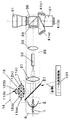
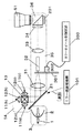
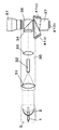
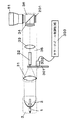
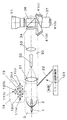
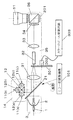
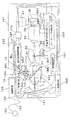
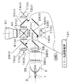
図1は、超高圧水銀ランプ1、および放物面鏡2を備えるランプユニット3と、発光ダイオード11(a)〜11(c)、および対応するレンズ12(a)〜12(c)を備える固体光源ユニット14と、照明領域に合わせた光束の成形および均一化を可能とするレンズ31,33、34、および均一性の高い照明を可能とするインテグレータ32を用いた照明ユニット35と、その照明ユニット35へ入射させる光束を切り替えることが可能な可動式ミラー21と、照明光を変調する光変調素子としての反射型表示素子41(a)〜41(c)と、投写レンズ51から構成される。 FIG. 1 includes an ultra-high
なお、上記の構成において、ランプユニット3は本発明の第1光発生手段を含む構成に相当し、超高圧水銀ランプ1は本発明の、放電による光源に相当する。また、固体光源ユニット14は本発明の第2光発生手段を含む構成に相当し、発光ダイオード11(a)〜11(c)は本発明の固体光源に相当する。また、レンズ31,33,34,プリズム36、ロッドインテグレータ32は本発明の集光系を構成し、反射型表示素子41(a)〜41(c)は本発明の光変調素子に相当し、投写レンズ51は本発明の投写手段に相当する。また、可動式ミラー21およびミラー部調整機構101は本発明の導光手段に相当する。 In the above configuration, the
なお、上記の構成において、超高圧水銀ランプ1の代わりに、ガラス管に不活性ガス等が封入されていてアーク放電によって発光体が形成されるキセノンランプや、発光効率が優れているメタルハライドランプ等のランプを用いても良い。また、フィラメントに通電することにより発光するクリプトンライト、ハロゲンランプ等のランプを用いてもよい。 In the above configuration, instead of the ultra-high
なお、放物面鏡2の代わりに、照明ユニット35側の光学系と整合するために、楕円面鏡など出射される光束の集光状態が異なるリフレクタを用いても良い。 Instead of the
また、発光ダイオード11(a)〜11(c)の代わりに、同様の半導体を材料とした半導体レーザや、Nd:YAGレーザなど固体レーザ、Arレーザーなどのガスレーザを用いても良い。 Further, instead of the light emitting diodes 11 (a) to 11 (c), a semiconductor laser using a similar semiconductor material, a solid state laser such as an Nd: YAG laser, or a gas laser such as an Ar laser may be used.
このとき、上述の超高圧水銀ランプ1と同様の白色光を、単色光で発光する発光ダイオードなどから得るには、図1に示すように、赤色、緑色、青色の3種類の発光ダイオード(発光ダイオード11(a)〜11(c)がそれぞれ各単色を発光する)から出射された光を合成するようにすればよいが、他に、紫外線に近い、またはその範囲の波長の光を出射し、その波長の光が入射すると赤色、緑色、青色に蛍光する蛍光体から出射された光を合成したり、さらに青色の光を出射する発光ダイオードと、青色の光が入射すると黄色に蛍光したり、または緑色や赤色に蛍光する蛍光体から出射された光を合成するなどの手法によって得られることが分かっている。 At this time, in order to obtain white light similar to that of the above-described ultrahigh
同様の手法によって、他の固体光源から白色の光を得ても良い。 White light may be obtained from other solid light sources by a similar method.
本実施の形態では、赤色、緑色、青色を出射する発光ダイオード11(a)〜11(c)を、クロスプリズム13などの合成手段によって色合成させることで、固体光源ユニット14から出射される光束が白色光となる構成を示している。 In the present embodiment, light beams emitted from the solid-state
このとき、紫外に近い、または紫外領域の波長の光を出射する発光ダイオードと、その波長の光が入射すると赤色、緑色、青色に蛍光する蛍光体を、発光ダイオードの発光部近傍に配置し、同じパッケージ内に収めた単色発光ダイオードで構成しても良い。 At this time, a light emitting diode that emits light of a wavelength close to ultraviolet or in the ultraviolet region, and a phosphor that fluoresces red, green, and blue when light of that wavelength is incident are disposed near the light emitting portion of the light emitting diode, A monochromatic light emitting diode housed in the same package may be used.
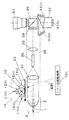
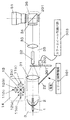
さらに、図2に示す構成例のように、青色の光を出射する発光ダイオードと、青色の光が入射すると黄色に蛍光する蛍光体を発光ダイオードの発光部近傍に配置し、同じパッケージ内に収めてなる白色発光ダイオード111や、赤色、緑色、青色の発光ダイオードを同じパッケージ内に収めてなる白色発光ダイオード111を用いた構成であっても良い。 Further, as in the configuration example shown in FIG. 2, a light emitting diode that emits blue light and a phosphor that emits yellow fluorescence when blue light is incident are arranged in the vicinity of the light emitting portion of the light emitting diode and housed in the same package. The white light-emitting
なお、レンズ12は、発光ダイオード11から出射された光束を照明ユニット35へ集光するために用いられており、レンズの代わりにリフレクタや、リフレクタとレンズを両方を用いた光学手段であっても良い。 The
以上のような構成を有する、本発明の実施の形態の投写型画像表示装置の動作を説明するとともに、これにより、本発明の画像表示方法の一実施の形態を図1を参照して説明する。 The operation of the projection-type image display apparatus according to the embodiment of the present invention having the above-described configuration will be described, and an embodiment of the image display method of the present invention will be described with reference to FIG. .
図1は、反射型表示素子41(a)〜41(c)の照明に固体光源ユニット14から出射される光束を用いる場合を示しており、固体光源ユニット14においては、レンズ12(a)〜12(c)を用いて集光された発光ダイオード11(a)〜11(c)の3色の光束がクロスプリズム13で色合成され、白色光として可動式ミラー21を介して照明ユニット35へ入射される。このとき、可動式ミラー21は、固体光源ユニット14側から出射される光束のほとんどが照明ユニット35へ入射される位置に移動させておけばよい。これにより、固体光源ユニット14から出射され、照明ユニット35へ達する光の光軸は、可動式ミラー21によって直角に屈曲する。 FIG. 1 shows a case in which a light beam emitted from the solid
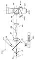
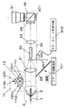
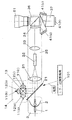
また、反射型表示素子41(a)〜41(c)の照明に超高圧水銀ランプ1から出射される光束を用いる場合は、図3に示すように、放物面鏡2を用いて効率よく集光された光束が、可動式ミラー21によって遮られることなく、照明ユニット35へ入射される。このとき可動式ミラー21はミラー部調整機構101の動作により、ランプユニット3側から出射される光束のほとんどを遮光しない位置に移動される。 In addition, when a light beam emitted from the ultrahigh
このように、簡素な可動式ミラー21によって、照明ユニット35側に入射される光束を固体光源ユニット14およびランプユニット3の、2つの光源装置から選択できる。 In this way, the light beam incident on the
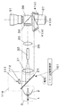
なお、図3は、ミラー部調整機構101が、照明ユニット35へ入射する光源装置を選択する可動式ミラー22を、ミラー平面と平行にスライドさせることによって、光束を選択する構成である。一方、図4のように、ランプユニット3の光束を照明ユニット35側に入射させる場合、可動式ミラー21を、ランプユニット3からの出射光束を遮光しない所定の角度に配置できるように、可動式ミラー23の1辺を回転軸として(図中黒丸に示す)、可動式ミラー21を回転移動させるといった構成であっても良い。 FIG. 3 shows a configuration in which the
つまり、上記のように、ランプユニット3からの光束と、固体光源ユニット14からの光束を可動式ミラー21などの導光手段を用いることで、照明ユニット35への入射光束を切り替えることができる構成であれば良い。 That is, as described above, the light beam from the
また、この可動式ミラー21は、ミラー部調整機構101によって稼働するものであるが、調整機構部は、手動でも、モータ等を用いた駆動回路によって自動的に駆動された構成であっても良い。 The
次に、照明ユニット35から投写レンズ51までの説明を行う。 Next, the description from the
可動式ミラー21の位置によって、選択された入射光は、レンズ31で集光され、ガラス柱や、ミラーの貼りあわせで構成された中空筒状のロッドインテグレータ32、レンズ33、さらに各光源装置から出射された白色の光源を3色に色分離するための色分離・合成プリズム37などの光学手段で構成された照明ユニット35を介して、3つの反射型表示素子41(a)〜41(c)を照明し、3つの反射型表示素子41で光変調された光を、再度色分離・合成プリズム37で色合成し、投写レンズ51を介して、スクリーン上に投写することで、拡大されたカラー画像が表示される。 Depending on the position of the
上記の構成においては、可動式ミラー21を介して照明ユニット35側に入射させる場合、可動式ミラー21で反射する際に、光の反射損失が発生する。 In the above configuration, when the light is incident on the
そこで本実施の形態においては、可動式ミラー21で反射されずに照明ユニット35へ入射可能となる光路側に、できるだけ多くの光束量を発生する光源装置を配置させるといった構成をとることで、投写型表示装置の最大出力をより大きなものにしている。 Therefore, in the present embodiment, projection is performed by arranging a light source device that generates as much light flux as possible on the optical path side that can enter the
この場合、今回の両光源を用いて考えると、発光ダイオードを用いた固体光源ユニット14より、発光効率が60〜70ルーメン/Wと高く、100Wの電力投入によって6000〜7000ルーメンもの光出力が可能な超高圧水銀ランプ1を光源とするランプユニット3が可動式ミラー21を介さない、すななわちランプユニット3からの出射光が照明ユニット35との間になる光軸が直線となる光路側となる図1のように配置させれば良い。 In this case, when considering both the light sources this time, the luminous efficiency is 60 to 70 lumens / W higher than the solid state
しかしながら、できるだけ少ない消費電力で、より多くの光出力を得たい場合には、低消費電力の光源装置から出射される光束を、可動式ミラー21を介さない光路側となるように配置させた方が良い。この場合、今回の両光源を用いて考えると、100Wの電力投入によって大きな光出力が可能な超高圧水銀ランプ1に比べて、最大でも1素子当たりの消費電力が1〜5Wと小さい発光ダイオード11(a)〜11(c)を光源とする固体光源ユニット14の方が低消費電力となりやすく、この固体光源ユニット14を可動式ミラー21を介さず、固体光源ユニット14からの出射光が照明ユニット35との間になる光軸が直線となる光路側となる、図1のランプユニット3と固体光源ユニット14が入れ替わったような配置(図示せず)とすれば良い。 However, when it is desired to obtain more light output with as little power consumption as possible, the light beam emitted from the light source device with low power consumption is arranged so as to be on the optical path side without the
ただし、投写型表示装置全体の大きさや、デザインの点から、ランプユニット3と固体光源ユニット14の位置を交換し、ランプユニット3から出射された光束を照明ユニット35へ入射する場合に、可動式ミラー21を介して入射させ、固体光源ユニット14から出射された光束を直接照明ユニット35へ入射させる構成であっても良い。 However, when the positions of the
従来例にて説明したように、明るさが1000ルーメン程度である投写型表示装置で使用されている、1mm程度の発光部を有し100W以上の電力投入が可能である超高圧水銀ランプは、管球内に常温では気化していない水銀が含まれているが、1mm程度の電極間アーク放電では、水銀が蒸発するためにかかる時間が1〜2分程度最大出力が得られるまで時間がかかるという問題がある。 As described in the conventional example, an ultra-high pressure mercury lamp that has a light emitting part of about 1 mm and can be powered up of 100 W or more, which is used in a projection display device whose brightness is about 1000 lumens, The tube contains mercury that is not vaporized at room temperature, but in the case of arc discharge between electrodes of about 1 mm, it takes time for the mercury to evaporate for about 1 to 2 minutes until the maximum output is obtained. There is a problem.
一方、発光ダイオードは、消費電力が5w程度とより小さく、電力投入から1秒以内にほぼ最大出力が出射される利点があるが、超高圧水銀ランプと同様発光部分が1mm角のものを用いた場合は、発光部から出射される光が100ルーメン程度であり、ビジネス商談用や小会議室用として要求されている明るさは出せないという問題があった。 On the other hand, the light-emitting diode has an advantage that the power consumption is smaller, about 5 w, and the maximum output is emitted within 1 second after the power is turned on. In this case, the light emitted from the light emitting unit is about 100 lumens, and there is a problem that the brightness required for business negotiations and small meeting rooms cannot be obtained.
かかる問題に対し、本実施の形態の投写型表示装置では、投写型表示装置の主電力投入後、可動式ミラー21を固体光源ユニット14側の光路中に配置させる。そして、超高圧水銀ランプ1と発光ダイオード11(a)〜11(c)の両光源を点灯させる。 To deal with this problem, in the projection display device according to the present embodiment, the
そして、電力供給後、十分な明るさに到達するまで時間がかかるアーク放電の超高圧水銀ランプ1を用いたランプユニット3から出射される光量が、本発明の所定の値としての、予め決めておいた十分な光量にほぼ達成、または、その光量に到達する予定時間が経過した後に、光路中の可動式ミラー21を移動させ、ランプユニット3から出射される光束を照明ユニット35へ入射させるように可動式ミラー21を切り替える。そのあと、発光ダイオード11(a)〜11(c)を消灯する。 Then, the amount of light emitted from the
この一連の動作によって、投写型表示装置の主電力投入直後から、1秒以内にほぼ最大の光出力が可能な発光ダイオード11(a)〜11(c)の瞬時点灯によって、投写画像の表示が可能となり、さらに、主電力投入から所定時間がたてば大出力が可能な超高圧水銀ランプ1によって、より大きな明るい投写画像の表示が可能となる。なお、上記の「あらかじめ決めていた光量」は、発光ダイオードの定格、実測値による光量などに基づいて定めてもよい。また、予定時間とは、本発明の所定時間の一例であるが、これはあらかじめ超高圧水銀ランプ1を発光させて、上記光量に達するまでの時間を実測した値を固定値としてそのまま用いてもよいし、図示しない光量センサによる測定値がこの実測した値に達するまでの時間としてもよい。 With this series of operations, the projected image is displayed by instantaneous lighting of the light emitting diodes 11 (a) to 11 (c) capable of almost the maximum light output within one second immediately after the main power of the projection display device is turned on. In addition, the ultrahigh
また、上記の説明においては、発光ダイオード11(a)〜(c)の点灯と超高圧水銀ランプ1との点灯は同時に行う期間があるものとしたが、可動式ミラー21により、照明ユニット35へ導入される光はいずれか一方から射出されるものに限られ、両者が同時に可動式ミラー21を介して照明ユニット35へ出射されることはない。これは以下の理由による。すなわち、超高圧水銀ランプと、半導体レーザーや発光ダイオードといった固体光源の単色光を、ダイクロイックフィルターによって合成する場合、超高圧水銀ランプの連続スペクトルのうち、半導体レーザーや発光ダイオードの光束をフィルターによってスペクトル合成するためには、固体光源の有するスペクトルに対応する波長域の光がフィルターで除去されるため、合成しても絶対光量としては、あまり増加しないといった問題点がある。 In the above description, it is assumed that there is a period in which the light emitting diodes 11 (a) to (c) are turned on and the ultrahigh
さらに、このときダイクロイックフィルターは、誘電体を多層にコーティングした光学部品であり、透過スペクトルが大きく変化するカットオフ波長の精度が5〜10ナノメートルといったオーダーで個体差が生じるため、確実に固体光源からの光と合成させるためには、ダイクロイックフィルターで除去する超高圧水銀ランプのスペクトル幅を大きく取らなければならないので、超高圧水銀ランプから出射された光束の利用効率が大きく低下してしまうという問題があるからである。 Furthermore, at this time, the dichroic filter is an optical component with a multilayer coating of dielectrics, and individual differences occur on the order of 5 to 10 nanometers in the accuracy of the cut-off wavelength at which the transmission spectrum changes greatly. In order to synthesize with the light from the dichroic filter, the spectral width of the ultra-high pressure mercury lamp removed by the dichroic filter must be made large, so that the utilization efficiency of the luminous flux emitted from the ultra-high pressure mercury lamp is greatly reduced. Because there is.
したがって、本発明においては、これらの問題を回避して、光束の利用効率を十分に確保できていることになる。 Therefore, in the present invention, these problems can be avoided and sufficient utilization efficiency of the luminous flux can be secured.
上記したように、本発明の構成を用いることで、電力投入直後の瞬時点灯を可能にし、時間がたてば従来通りの大きな光出力が得られるという効果を有する投写型表示装置を実現できる。 As described above, by using the configuration of the present invention, it is possible to realize a projection display device having an effect of enabling instantaneous lighting immediately after power-on and obtaining a large light output as usual over time.
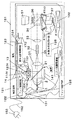
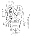
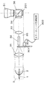
また、光変調素子として、反射型表示素子41(a)〜41(c)に代えて発光ダイオード11(a)〜11(c)の各色に対応して設けられた3つの透過型表示素子61(a)〜61(c)を用いてもよい。図15は透過型表示素子を用いた場合の構成図である。図15に示すように、発光ダイオード11(a)〜(c)からの光を色合成することなく、それぞれ透過型表示素子61(a)〜61(c)に直接入射させることが可能となる。 Further, as the light modulation elements, three
この場合、固体光源ユニットは、発光ダイオード11(a)〜11(c)のそれぞれに応じた3つの固体光源ユニット14(a)〜14(c)から構成されることになる。また導光手段として、透過型表示素子61(a)、61(c)の入射側手前にそれぞれ配置された反射ミラー24(a)、24(c)、およびランプユニット3からの出射光の光軸上に配置された反射ミラー24(c)の3つの反射ミラーと、ランプユニット3からの出射光の光軸上に配置されたダイクロイックフィルター62(a)および透過型表示素子61(b)の入射側手前に配置されたダイクロイックフィルター62(b)の2つのダイクロイックフィルターとを用い、各々制御することで、少なくとも、固体光源ユニットと透過型表示素子61(a)〜61(c)との間には照明ユニット35のような集光系を設ける必要がない構成となっている。なお、この構成においては、色分離・合成プリズム37の代わりに、反射ミラー24(a)〜24(c)およびダイクロイックフィルター62(a)、62(b)によって色分離されたランプユニット3、または固体光源ユニット14(a)〜14(c)から出射され透過型表示素子61(a)〜61(c)を透過して光変調された光を色合成するするためのクロスプリズム40を用いている。 In this case, the solid light source unit is configured by three solid light source units 14 (a) to 14 (c) corresponding to the respective light emitting diodes 11 (a) to 11 (c). Further, as the light guide means, the reflection mirrors 24 (a) and 24 (c) disposed in front of the transmission side display elements 61 (a) and 61 (c), respectively, and the light emitted from the
これにより、固体光源としてのユニット14(a)〜14(b)において、図1のクロスプリズム13のような構成が不必要となるため、投写型表示装置における光学系全体の簡素化に繋がるという利点がある。なお、図15においては、照明ユニット35として、レンズ31,ロッドインテグレータ32等の代わりに、レンズアレイ38(a)、38(b)およびレンズ39を用いた構成を示した。 This eliminates the need for the configuration of the
また、図15に示す構成においては、照明ユニット35は、本発明の集光系を構成しない。要するに、本発明は、ランプユニット3に含まれる第1光発生手段と、固体光源ユニット4または4(a)〜4(c)に含まれる第2光発生手段とからの光が、選択的に透過型表示素子61(a)〜61(c)または反射型表示素子41(a)〜41(c)として実施される光変調素子に導かれるような構成であればよく、第1光発生手段、第2光発生手段と、光変調素子との間の集光系その他光学的な構成の有無によって限定されるものではない。 Moreover, in the structure shown in FIG. 15, the
(実施の形態2)
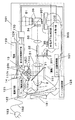
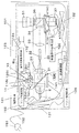
図5は、実施の形態1の投写型表示装置に関し、ランプユニット3他を駆動する電源等を含めた投写型表示装置151の概略的な全体構成図を示す。(Embodiment 2)
FIG. 5 shows a schematic overall configuration diagram of the
図5において、図1〜4と同一または相当部には、同一符号を付し、詳細な説明は省略する。ただし、可動式ミラー21はその両面が反射面となっており、図5中の配置においては、ランプユニット3からの光、固体光源ユニット14からの光の両方を反射可能となっている。また、電源回路121はランプユニット3およびランプ制御回路122、ファン制御回路125および冷却ファン131,132に電力を供給する手段、ランプ制御回路122はランプユニット3の光出力のON/OFF、光量を制御する手段、電池123は投写型表示装置151の独立した内蔵電源であって、固体光源ユニット14および固体光源制御回路124に電力を供給する手段、固体光源制御回路124は固体光源ユニット14内の発光ダイオード11(a)〜11(c)を一括または個別に出力のON/OFF、光量を制御する手段である。 In FIG. 5, the same or corresponding parts as in FIGS. However, both sides of the
また、ファン制御回路125は、ランプユニット3を冷却する冷却ファン131および反射型表示素子41(a)〜41(c)を冷却する冷却ファン132の動作を制御する手段であり、映像信号処理回路126は、有意な映像信号によって反射型表示素子41(a)〜41(c)を駆動させる手段である。また、電源ライン152は、その一端がACコンセント153に接続され、電源回路121に外部からの電力供給を導く手段である。また、光量センサ141はランプユニット3から出射され、可動式ミラー21で反射された光の光量を測定する手段である。 The
また、制御手段170は、外部電力、電池123の両方により駆動し、ランプ制御回路122,固体光源制御回路124,ファン制御回路125およびミラー部調整機構101の動作を、ユーザ入力および/または、光量センサ141からの検出値に基づき、自動的に、監視、制御する手段である。なお、上記の構成において、電源回路121は本発明の第1電源に、電池123は本発明の第2電源にそれぞれ相当し、ミラー部調整機構101および制御手段170は、本発明の制御手段を構成する。また、光量センサ141は本発明の光量測定手段に相当する。 The
以上のような構成を有する本発明の実施の形態2による投写型表示装置152の動作について、以下、説明を行う。 The operation of the
まず、投写画像において明るさがあまり必要ない場合には、1素子当たりの消費電力が小さな発光ダイオード11(a)〜11(c)のみを点灯させ、超高圧水銀ランプ1は点灯させない。固体光源ユニット14から出射された光束を照明ユニット35へ入射させるように可動式ミラー21を、固体光源ユニット14の光路中に配置することで、投写レンズ51から出射される光束が固体光源ユニット14からの光束となり、アーク放電の超高圧水銀ランプ1を点灯させた場合より明るくはないが、消費電力が少なくて済むことを利用して電池123で駆動させ、ACコンセント153と投写型表示装置の筐体をつなげる電源ライン152が無いコードレスの投写型表示装置151として使用する。 First, when not much brightness is required in a projected image, only the light emitting diodes 11 (a) to 11 (c) with low power consumption per element are turned on, and the ultrahigh
また投写画像に明るさが必要な場合には、ACコンセント153と投写型表示装置の筐体をつなげる電源ライン152を用いて外部から電力供給し、消費電力は大きくなるが大きな光出力も得られる超高圧水銀ランプ1を点灯させ、ランプユニット3から出射された光束を照明ユニット35へ入射させるように可動式ミラー21を、ランプユニット3の光路中から排除することで、投写レンズ51から出射される光束がランプユニット3からの光束となり、大きな光出力が可能な投写型表示装置151として使用できる。 In addition, when the projected image needs brightness, power is supplied from the outside using a
このように、投写画像に明るさはあまり必要ない場合、コードレスによって光源を点灯させた状態で自由に持ち運びが可能になり、自由に持ち運びする必要なく、外部AC電源からの電力供給ができる状況においては、従来通りの大きな光出力が得られるというかたちで、電池駆動によるコードレス化によって可搬性を可能にし、AC電源からの電力供給が可能な場合には、従来通りの大きな出力が得られるという効果を有する投写型表示装置151を実現できる。 In this way, when the projected image does not require much brightness, it can be freely carried with the light source turned on cordlessly, and can be supplied with power from an external AC power source without having to carry freely. In the form that the conventional large light output can be obtained, the portability is made possible by the cordless operation by the battery drive, and when the power supply from the AC power source is possible, the conventional large output can be obtained. Can be realized.
なお、固体光源ユニット14を駆動させる電池123としては、アルカリ乾電池や、マンガン乾電池などの乾電池、リチウムイオン電池や、ニッケル水銀電池、ニッケルカドミウム電池などの充電池、さらにメタノール燃料電池、固体高分子形燃料電池などの燃料電池、など様々な蓄電池や発電電池を用いて良い。 The
次に、投写型表示装置151による省電力化のための制御回路170による制御動作を述べる。 Next, a control operation by the
主電源起動後当初は、実施の形態1にて説明したように、電池123で投写型表示装置151を動作させるため、超高圧水銀ランプ1を点灯させないので、制御回路170は、この超高圧水銀ランプ1の動作状態(非点灯)に基づき、ファン制御回路125を制御して、超高圧水銀ランプ1を主に冷却するファン131への電力供給を制限または停止させたり、超高圧水銀ランプ1から出射される光量に対応できるように設定された反射型表示素子41(a)〜41(c)を主に冷却するファン132への電力供給を制限または停止させたりすることで、投写型表示装置151全体としての消費電力を軽減させることで、固体光源ユニット14で投写できる時間をより長くすることが可能となる効果が得られる。 Initially after starting the main power supply, as described in the first embodiment, since the
さらに、映像信号処理回路126についても、表示するために必要な入力信号処理のみに電力供給を行わせることで、投写型表示装置151全体としての消費電力を軽減させることで、固体光源ユニット14で投写できる時間をより長くすることが可能となる効果が得られる。 Furthermore, the solid-state
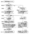
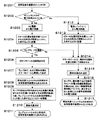
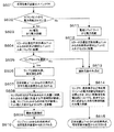
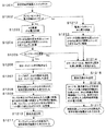
次に、図6を参照して、前述したように、本投写型表示装置151を用いた場合に、大きな効果がある投写型表示装置の立ち上がり手順の制御について説明する。 Next, referring to FIG. 6, as described above, control of the start-up procedure of the projection display device that has a great effect when the
まず、投写型表示装置151の主電力スイッチ(図示せず)をONにする(S601)。 First, a main power switch (not shown) of the
そして、電源回路121の状態を参照して、投写型表示装置151がACコンセント153から電力供給を受けているかどうかの判定を行う(S602)。このとき、AC電源から電力供給を受けている場合(S603)と、そうではなく電池123から電力供給を受けている場合(S611)で、そのあとの手順が異なる。 Then, with reference to the state of the
そして、AC電源から電力供給されている場合は、まず、可動式ミラー21の位置を、固体光源ユニット14からの出射光が照明ユニット35に入射するように配置する(S604)。 When power is supplied from the AC power source, the position of the
そして、特にAC電源から電力供給している場合では、超高圧水銀ランプ1を用い、明るい投写画像を表示させたい(ランプモード)か、それとも消費電力を低くするために、発光ダイオード11(a)〜11(c)を用い、投写画像を表示させたい(固体光源モード)か、をユーザーによって選択可能とし(S605)、例えば、超高圧水銀ランプ1を用いるランプモードが選択されている場合であれば、超高圧水銀ランプ1と発光ダイオード11(a)〜11(c)の両方を点灯させる(S606)。 In particular, in the case where power is supplied from an AC power source, it is desired to use the ultrahigh
このとき、可動式ミラー21の位置は、前段階で固体光源ユニット14からの出射光が照明ユニット35に入射するように配置させておいたので、固体光源ユニット14の光源である発光ダイオード11(a)〜11(c)からの出射光が、まず投写レンズ51から出射されることとなる(S607)。 At this time, the position of the
そして、超高圧水銀ランプ1の明るさが、発光ダイオード11(a)〜11(c)から出射される光量よりも大きくなったとか、超高圧水銀ランプ1から出射される光の所定の明るさに達したなど、予め決めておいた光量に到達したことを確認したり、または、その予め決めておいた光量に到達する予定時間を事前に測定しておき、超高圧水銀ランプ1が点灯、または投写型表示装置151のスイッチをONしてから、この所定の明るさに到達する予定時間が経過した後、ランプユニット3からの出射光が照明ユニット35側に入射するように、可動式ミラー21を移動させる(S608)。本実施の形態においては、光量センサ141が測定する実測値としての光量が、あらかじめ測定され、制御手段170内にプリセットされている固定値に達するまでの時間を予定時間とした。 Then, the brightness of the ultra high
そして、照明ユニット35側へ入射される光が、ランプユニット3の超高圧水銀ランプ1の光束だけとなった後、固体光源ユニット14の発光ダイオード11(a)〜11(c)を消灯させる(S609)。 And after the light which injects into the
このように、この作業手順によって、外部AC電源から電力供給され、ランプモードを選択されている場合でも、瞬時点灯を可能にしながら、超高圧水銀ランプ1による従来同様の明るい投写画像が得られる(S610)という効果がある。 Thus, according to this work procedure, even when power is supplied from an external AC power source and the lamp mode is selected, a bright projected image similar to the conventional one using the ultrahigh
次に、第2例を説明する。ACコンセント153から外部電力が供給されていない状態で、投写型表示装置151の主電力スイッチがONされた場合、電池123から電力供給されていることが検知され(S611)、まず可動式ミラー21の位置を固体光源ユニット14からの出射光が照明ユニット35に入射するように配置する(S612)。 Next, a second example will be described. When the main power switch of the
このとき、超高圧水銀ランプ1は消灯したまま、発光ダイオード11(a)〜11(c)のみ点灯させる(S613)。 At this time, only the light emitting diodes 11 (a) to 11 (c) are turned on while the ultrahigh
なお、AC電源から電力供給を受けている場合であっても、ランプモードを選択していない場合(S605)も、同様に超高圧水銀ランプは消灯したまま、発光ダイオードのみ点灯させる(S613)。 Even when the power supply is supplied from the AC power source, when the lamp mode is not selected (S605), only the light emitting diode is turned on with the ultrahigh pressure mercury lamp turned off (S613).
そして、この電池123から電力供給されている場合は、投写型表示装置151全体としても省電力化するために、発光ダイオード11(a)〜11(c)のみ点灯している状況なので、超高圧水銀ランプ1や反射型表示素子41(a)〜41(c)を主に冷却している冷却ファン131,132への電力供給を、ファン制御回路125の制御により制限したり停止させたりし、さらに映像信号処理回路126についても、表示するために最小限必要な電力供給のみさせる(S614)といったことを行う。 When power is supplied from the
このように、この作業手順によって、電池123から電力供給されている場合には、より低消費電力化が可能となり、固体光源ユニット14による長時間の投写画像(S615)が可能になるという効果が得られる。 As described above, when power is supplied from the
なお、上記の作業手順に示された判断を要する項目については、投写型表示装置151内の制御手段170が行うものとして説明を行ったが、これはソフトウェア(プログラム)によって自動的に判断させてもよい。また、判断はユーザが行い、制御手段170はこれを受け付けるインタフェースとして動作させるようにしてもよい。 In addition, although it has been described that the items that require the determination shown in the above work procedure are performed by the control means 170 in the
また、この作業手順に示された可動式ミラー21の移動については、制御手段170として、ソフトウェア(プログラム)によって、自動的に駆動できるモータつき可動式ミラー調整機構101を自動的に移動させるものとしたが、また手動で移動させてもよい。 Regarding the movement of the
また、この作業手順に示された光源の点灯、消灯については、ランプ制御回路122および固体光源制御回路124によって制御させるものとしたが、これはソフトウェア(プログラム)によって自動的に点灯、消灯させても、ユーザーが手動で行ってもよい。 In addition, lighting and turning off of the light source shown in this work procedure are controlled by the
また、図1では、照明ユニット35として、3枚のレンズ31,33および34とロッドインテグレータ32とプリズム36を記しているが、照明ユニット35内に示した照明ユニット35内に入射した光を照明すべき反射型表示素子41(a)〜41(c)側へ照明すべき大きさに合わせた形状および均一性をもつ照明光に変換する光学手段として光路中にレンズを、光路折り曲げのためのプリズムを図示したが、レンズが無いものや、複数個の単レンズを組み合わせたもの、また図に示されていないがミラー等の光学手段が含まれた光学系であってもよい。 In FIG. 1, three
さらに、図1では照明ユニット35部の均一照明を可能にする光学手段としてロッドインテグレータ32を用いた構成であるが、複数のレンズを2次元状に配置させたレンズアレイを用いた構成であっても良い。 Further, in FIG. 1, the
さらに、上記の投写型表示装置151では、画像表示素子として、反射型表示素子41(a)〜41(c)を用いたが、透過型表示素子や、アレイ状に配置された微小ミラーによって反射方向を変化できるDMD(ディジタルマイクロミラーデバイス)のような表示素子で構成された投写型表示装置であってもよい。 Furthermore, in the
さらに、上記の投写型表示装置151では、図1のように固体光源としての発光ダイオード11(a)〜11(c)を各単色で1個、と最小の個数で記載したが、特に各単色で1個と限定するものではなく、複数個の発光ダイオードを用いて構成された投写型表示装置であってもよい。 Further, in the above-described
さらに、上記の投写型表示装置151では、図1のようにアーク放電のランプとしての超高圧水銀ランプを用いた1個のランプユニット3と、固体光源としての発光ダイオードを用いた1個の固体光源ユニット14で記載したが、特に1個と限定するものではなく、複数個のランプユニット3と、複数個の固体光源ユニット14で構成された投写型表示装置であってもよい。 Further, in the above-described
(実施の形態3)
本発明の実施の形態3について、図面を参照しながら説明する。(Embodiment 3)
A third embodiment of the present invention will be described with reference to the drawings.
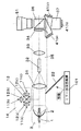
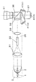
図7に、本実施の形態3にかかる投写型表示装置の概略構成を示す。なお、図1と同一または相当部には、同一符号を付し、詳細な説明は省略する。 FIG. 7 shows a schematic configuration of the projection display apparatus according to the third embodiment. The same or corresponding parts as those in FIG. 1 are denoted by the same reference numerals, and detailed description thereof is omitted.
図1に示す実施の形態1と本実施の形態とは、基本的には同一だが、以下の点で異なる。すなわち、図7で示されているように、光変調素子である反射型表示素子201が3つから1つになったこと、反射型表示素子201前の色分離・合成プリズム37の代わりに、ロッドインテグレータ32の前に、光路を通過するように配置されたカラーホイール301と、カラーホイール301を回転させる駆動用モータ302と、カラーホイール制御回路303が加わった点が異なる。 The first embodiment shown in FIG. 1 and the present embodiment are basically the same, but differ in the following points. That is, as shown in FIG. 7, the number of
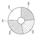
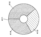
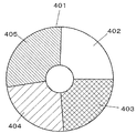
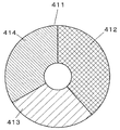
ここで図9,10にカラーホイール301の具体例を示す。図9に示すカラーホイール401は、円を光の三原色にそれぞれ対応して着色された領域403〜405および透明の領域402を有し、駆動用モータ302が回転すると、光路はこの領域402〜405を通過する。また、図10に示すカラーホイール411は、透明の領域を持たず、光の三原色にそれぞれ対応して着色された領域412〜414のみを有する。 Here, a specific example of the
カラーホイール301を回転させることで、反射型表示素子201を照明する光線は時系列で分割着色され、各色の光で照明されている期間に、1つの反射型表示素子201で形成された各色の画像を、スクリーン上に投写することでカラー画像を実現させている。 By rotating the
この投写型表示装置では、1画面を形成する時間(約17ms)内に表示された画像は、異なる色で表示された画像であっても、目に入った光が一定時間認識されているので、まるで異なる色の画像が同時に光っているように錯覚を起こし、カラー画像を表示することが可能となっている。 In this projection display apparatus, even if an image displayed within a time period for forming one screen (about 17 ms) is an image displayed in a different color, the light that has entered the eyes is recognized for a certain period of time. It is possible to display a color image by creating an illusion that images of different colors are shining simultaneously.
このように、反射型表示素子201が1つの光学系であっても、可動式ミラー21によって、図7に示すように、固体光源ユニット14から出射された光束を照明ユニット35へ入射させたり、図8に示すように、可動式ミラー22を移動させることで、ランプユニット3から出射された光束を照明ユニット35へ入射させたり、選択することが可能となり、本実施の形態1と同様の効果が得られることがわかる。 Thus, even if the
さらに、図7に示された光学系を用いた場合、従来のランプと同様の超高圧水銀ランプ1は1つの光源から白色光が出射されていたため、カラーホイール301によって白色光を色分離フィルターによって時系列に色分離しなければいけなかったが、発光ダイオード11(a)〜11(c)のような固体光源は、単色光源であり、図7のように、3色の発光ダイオード11(a)〜11(c)を用いた固体光源ユニット14であれば、各色の発光ダイオード11(a)〜11(c)の点灯時間をずらすことで、時系列に色分離することが容易である。 Further, when the optical system shown in FIG. 7 is used, white light is emitted from a single light source in the ultra-high
このため、可動式ミラー21を挿入し、固体光源ユニット14から出射された光束を照明ユニット35へ入射する場合、カラーホイール301を回転駆動することが必須ではなくなる。このため、カラーホイール301が、図9のようなカラーホイール401のような4色フィルターで構成されている場合は、カラーホイール401を通過光が白色となる領域402で停止させておくことで、カラーホイール401を動作させるための電力が必要なくなり、消費電力を低減できるといった効果が得られる。 For this reason, when the
また、固体光源ユニット14から出射される光束からランプユニット3から出射される光束へ、照明ユニット35へ入射される光束を時間経過によって変更する、AC電源からの電力供給、およびランプモードで立ち上げる場合には、カラーホイール301を回転させるモータ302の回転数が急峻に立ち上がらないことから、ランプユニット3から出射される光束へ切り替えられたと同時にカラーホイール301を回転させたのでは間に合わないので、この場合は、固体光源ユニット14から出射された光束を利用している場合であっても、発光ダイオード11(a)〜11(c)の点灯時間と同期するように、カラーホイール301を回転させるほうがよい。 Further, the luminous flux incident on the
なお、図10のように、白色の領域がないカラーホイール411の場合もまた、発光ダイオード11(a)〜11(c)の点灯時間と同期して、ダイオードの発光色と、光路が通過する領域の色とが一致するように、カラーホイール411は回転させることが望ましい。 In the case of the
次に、図11には、実施の形態2同様、ランプユニット3他を駆動する電源等を含めた投写型表示装置161の概略的な全体構成図を示す。ただし図11において、図5および図7と同一または相当部には、同一符号を付し、詳細な説明は省略する。また、制御手段170は、カラーホイール制御回路303の動作をも制御する点が、図5に示す例と異なる。以下、投写型表示装置161による省電力化のための制御回路170による制御動作を、図12のフローチャートを参照して述べる。 Next, FIG. 11 shows a schematic overall configuration diagram of the
まず、投写型表示装置161の主電力スイッチ(図示せず)をONにする(S1201)。 First, a main power switch (not shown) of the
そして、電源回路121の状態を参照して、投写型表示装置161がACコンセント153から電力供給を受けているかどうかの判定を行う(S1202)。このとき、AC電源から電力供給を受けている場合(S1203)と、そうではなく電池123から電力供給を受けている場合(S1212)で、そのあとの手順が異なる。 Then, referring to the state of the
そして、AC電源から電力供給されている場合は、まず、可動式ミラー21の位置を固体光源ユニット14からの出射光が照明ユニット35に入射するように配置する(S1204)。 When power is supplied from the AC power source, first, the
そして、特にAC電源から電力供給している場合では、超高圧水銀ランプ1を用い、明るい投写画像を表示させたい(ランプモード)か、それとも消費電力を低くするために、発光ダイオード11(a)〜11(c)を用い、投写画像を表示させたい(固体光源モード)か、をユーザーによって選択可能とし(S1205)、例えば、超高圧水銀ランプ1を用いるランプモードが選択されている場合であれば、カラーホイール301を回転させ(S1206)、超高圧水銀ランプ1を点灯させ、発光ダイオード11(a)〜11(c)をカラーホイール301と同期して時系列で順次点灯させる(S1207)。この場合の発光ダイオード11(a)〜11(c)は、カラーホイール301と同期して選択的に点灯されており、単色発光ダイオード11(a)〜11(c)のいずれか、照明ユニット35の光路中に位置するカラーホイール301の領域の色と同じ色のもの(図9に示すカラーホール401の領域403〜405の対応するいずれか)が点灯し、カラーホイール301の白色領域(図9に示すカラーホール401の領域402に相当する)の場合のみ、発光ダイオード11(a)〜11(c)の3色すべてが点灯するといった点灯形態となる。 In particular, in the case where power is supplied from an AC power source, it is desired to use the ultrahigh
このとき、可動式ミラー21の位置は、前段階で固体光源ユニット14からの出射光が照明ユニット35に入射するように配置させておいたので、固体光源ユニット14の光源である発光ダイオード11(a)〜11(c)からの出射光が、まず投写レンズから出射することとなる(S1208)。 At this time, the position of the
そして、超高圧水銀ランプ1の明るさが、発光ダイオード11(a)〜11(c)から出射される光量よりも大きくなったとか、超高圧水銀ランプ1から出射される光の所定の明るさに達したなど、予め決めておいた光量に到達したことを確認したり、または、その予め決めておいた光量に到達する予定時間を事前に測定しておき、超高圧水銀ランプ1が点灯、または投写型表示装置161のスイッチONしてから、この所定の明るさに到達する予定時間が経過した後、ランプユニット3からの出射光が照明ユニット35側に入射するように、可動式ミラー21を移動させる(S1209)。実施の形態2と同様、本実施の形態においても、光量センサ141が測定する実測値としての光量が、あらかじめ測定され、制御手段170内にプリセットされている固定値に達するまでの時間を予定時間とした。 Then, the brightness of the ultra high
そして、照明ユニット35側へ入射される光が、ランプユニット3の超高圧水銀ランプ1の光束だけとなったので、固体光源ユニット14の発光ダイオード11(a)〜11(c)を消灯させる(S1210)。 And since the light which injects into the
このように、この作業手順によって、外部AC電源から電力供給され、ランプモードを選択されている場合でも、瞬時点灯を可能にしながら、超高圧水銀ランプ1による従来同様の明るい投写画像が得られる(S1211)という効果がある。 Thus, according to this work procedure, even when power is supplied from an external AC power source and the lamp mode is selected, a bright projected image similar to the conventional one using the ultrahigh
さらに、ACコンセント153から外部電力が供給されていない状態で、投写型表示装置161の主電力スイッチがONされた場合、電池123から電力供給いることが検知され(S1212)、まず可動式ミラー21の位置を固体光源ユニット14からの出射光が照明ユニット35に入射するように配置する(S1213)。 Further, when the main power switch of the
そして、この場合、カラーホイール301が白色領域を持つもの(図9に示すカラーホイール401の白色領域402に相当)であれば、これを通過するように、照明ユニット35の光路に位置する領域が白色領域となるように配置させた状態で停止させておく(S1214)。これによって、カラーホイール301を回転させるモータ302の消費電力を低減できるという効果が得られる。 In this case, if the
このとき、超高圧水銀ランプ1は消灯したまま、発光ダイオード11(a)〜11(c)のみを一斉点灯させる(S1215)。 At this time, only the light emitting diodes 11 (a) to 11 (c) are turned on all at once while the ultrahigh
また、AC電源から電力供給を受けている場合であっても、ランプモードを選択していない場合(S1205)も、同様に超高圧水銀ランプ1は消灯したまま、カラーホイール301を所定の位置で停止させ(S1214)、発光ダイオード11(a)〜11(c)のみ点灯させる(S1215)。 Even when the power supply is supplied from the AC power source, when the lamp mode is not selected (S1205), the
そして、この電池から電力供給されている場合は、投写型表示装置161全体としても省電力化するために、発光ダイオード11(a)〜11(c)のみ点灯している状況なので、超高圧水銀ランプ1や反射型表示素子201を主に冷却している冷却ファン131,132への電力供給を、ファン制御回路125の制御により制限したり停止させたりし、さらに、映像信号処理回路126についても、表示するために最小限必要な電力供給のみさせる(S1216)といったことを行う。 When power is supplied from this battery, since only the light emitting diodes 11 (a) to 11 (c) are lit to save power for the
このように、本実施の形態においても実施の形態2と同様、電池123から電力供給されている場合には、より低消費電力化が可能となり、固体光源ユニット14による投写画像表示(S1217)が可能になるという効果が得られる。 Thus, in the present embodiment as well, in the same way as in the second embodiment, when power is supplied from the
なお、上記の作業手順に示された判断を要する項目については、投写型表示装置161内の制御手段170が行うものとして説明を行ったが、これはソフトウェア(プログラム)によって自動的に判断させてもよい。また、判断はユーザが行い、制御手段170はこれを受け付けるインタフェースとして動作させるようにしてもよい。 In addition, although it has been described that the items that require the determination shown in the above work procedure are performed by the
また、この作業手順に示された可動式ミラー21の移動については、制御手段170として、ソフトウェア(プログラム)によって、自動的に駆動できるモータつき可動式ミラー調整機構101を自動的に移動させるものとしたが、また手動で移動させてもよい。 Regarding the movement of the
また、この作業手順に示された光源の点灯、消灯については、ランプ制御回路122および固体光源制御回路124によって制御させるものとしたが、これはソフトウェア(プログラム)によって自動的に点灯、消灯させても、ユーザーが手動で行ってもよい。 In addition, lighting and turning off of the light source shown in this work procedure are controlled by the
また、この作業手順に示されたカラーホイール301の発光ダイオード11(a)〜11(c)との同期や、所定の位置での停止については、投写型表示装置161内のカラーホイール制御回路303の制御によって行うものとしたが、これはソフトウェア(プログラム)によって自動的に駆動させても、ユーザーが手動で行ってもよい。 The color
なお上記の説明においては、カラーホイール301が図9に例示するような4色フィルターとして説明を行ったが、図10に例示するようなカラーホイール301が赤色、青色、緑色の3色フィルターの場合は、電池123から電力供給していても、カラーフィルター301は必ず発光ダイオード11(a)〜11(c)の発光色と同期させることが必要である。このとき、上記の説明における図12の照明ユニット35の光路に位置する色フィルタを白色となるように配置させた状態で停止させておく(S1214)という動作は、カラーホイール301は発光ダイオード11(a)〜11(c)の発光色と同期させて回転させる、という動作へと変更されることとなる。 In the above description, the
なお、本発明にかかるプログラムは、上述した本発明の投写型表示装置の制御手段の機能の全部または一部をコンピュータにより実行させるためのプログラムであって、コンピュータと協働して動作するプログラムであってもよい。 The program according to the present invention is a program for causing a computer to execute all or part of the functions of the control means of the projection display apparatus according to the present invention described above, and is a program that operates in cooperation with the computer. There may be.
また、本発明は、上述した本発明の投写型表示装置の制御手段の全部または一部の手段の全部または一部の機能をコンピュータにより実行させるためのプログラムを記録した媒体であり、コンピュータにより読み取り可能且つ、読み取られた前記プログラムが前記コンピュータと協動して前記機能を実行する記録媒体であってもよい。 Further, the present invention is a medium in which a program for causing a computer to execute all or part of the functions of all or part of the control means of the projection display device of the present invention described above is read by the computer. It may be a recording medium in which the read program executes the function in cooperation with the computer.
また、本発明のプログラムを記録した、コンピュータに読みとり可能な記録媒体も本発明に含まれる。 Further, the present invention includes a computer-readable recording medium that records the program of the present invention.
また、本発明のプログラムの一利用形態は、コンピュータにより読み取り可能な記録媒体に記録され、コンピュータと協働して動作する態様であっても良い。 Further, one usage form of the program of the present invention may be an aspect in which the program is recorded on a computer-readable recording medium and operates in cooperation with the computer.
また、本発明のプログラムの一利用形態は、伝送媒体中を伝送し、コンピュータにより読みとられ、コンピュータと協働して動作する態様であっても良い。 Further, one usage form of the program of the present invention may be an aspect in which the program is transmitted through a transmission medium, read by a computer, and operated in cooperation with the computer.
また、本発明のデータ構造としては、データベース、データフォーマット、データテーブル、データリスト、データの種類などを含む。 The data structure of the present invention includes a database, data format, data table, data list, data type, and the like.
また、記録媒体としては、ROM等が含まれ、伝送媒体としては、インターネット等の伝送機構、光・電波・音波等が含まれる。 The recording medium includes a ROM and the like, and the transmission medium includes a transmission mechanism such as the Internet, light, radio waves, sound waves, and the like.
また、上述した本発明のコンピュータは、CPU等の純然たるハードウェアに限らず、ファームウェアや、OS、更に周辺機器を含むものであっても良い。 The computer of the present invention described above is not limited to pure hardware such as a CPU, and may include firmware, an OS, and peripheral devices.
なお、以上説明した様に、本発明の構成は、ソフトウェア的に実現しても良いし、ハードウェア的に実現しても良い。 As described above, the configuration of the present invention may be realized by software or hardware.
本発明にかかる投写型表示装置は、従来と同等の明るさを実現させるとともに、電力供給直後から明るい投写画像を表示でき、可搬性に優れるという効果が期待できる投写型表示装置など、画像を投写することが可能な表示装置に適応できる。 The projection display device according to the present invention projects an image such as a projection display device that realizes brightness equivalent to that of the prior art, can display a bright projection image immediately after power supply, and can be expected to have excellent portability. It is possible to adapt to a display device that can do this.
【0005】
っているが、発光部分である半導体接合部分のジャンクション温度が100〜150℃以下との熱的制約があるため、投入可能な電力は、近年でも、1mm角の素子に対して、最大投入電力が1〜5W程度であり、超高圧水銀ランプなどに比べて、消費電力がかなり小さいものがほとんどであり、最も発光効率が高い緑色発光ダイオードで約40ルーメン/Wなので、1素子では200ルーメン程度と、100Wの超高圧水銀ランプに比べてかなり小さい。したがって、超高圧水銀ランプ100Wと同様の光束を得るためには、発光ダイオードを30個程度用いる必要があり、これは発光部の面積をかなり大きなものとしてしまい、かつ、発光ダイオードから出射されるすべての高速を集光することはできず、かつ、発光部分が広い範囲に散在した発光ダイオードから出射される多くの光束を集光することは困難であり、実質的な光出力は低下してしまう。
[0022] 本発明はこのような問題に鑑みてなされたものであり、従来と同等の明るさと、電力供給直後から必要な出力を得ることとが同時に可能な投写型表示装置を実現することを目的とする。
【発明の開示】
[0023] 上記の目的を達成するために、第1の本発明は、放電またはフィラメント通電による光源を有し、これにより白色光を発生する第1光発生手段と、
複数の固体光源を有し、これにより3種類以上の単色光を発生する第2光発生手段と、
前記白色光または前記単色光を変調させる光変調素子と、
前記白色光または前記単色光を選択的に前記光変調素子へ導く導光手段と、
前記光変調素子により変調された光を投写する投写手段とを備えた投写型表示装置である。
[0024] また、第2の本発明は、光の三原色にそれぞれ対応した第1、第2および第3の領域を有し、回転することより前記第1、第2および第3の領域が時系列で光路中に位置するよう配置されたカラーホイールを備えた、第1の本発明の投写型表示装置である。
[0025] また、第3の本発明は、前記第2光発生手段は、光路中に位置する前記カラーホイールのいずれかの領域に対応する色と前記単色光の色とが一致するように、前記固体光源を選択的に点灯する、第2の本発明の投写型表示装置である。[0005]
However, since there is a thermal restriction that the junction temperature of the semiconductor junction part, which is the light emitting part, is 100 to 150 ° C. or less, the power that can be input is the maximum input power for a 1 mm square element even in recent years. Is about 1 to 5 W, and most of them consume much less power than ultra-high pressure mercury lamps, etc. The green light emitting diode with the highest luminous efficiency is about 40 lumens / W, so one element is about 200 lumens. It is considerably smaller than a 100 W ultra high pressure mercury lamp. Therefore, in order to obtain the same luminous flux as that of the ultra-high pressure mercury lamp 100W, it is necessary to use about 30 light emitting diodes, which considerably increases the area of the light emitting part and all the light emitted from the light emitting diodes. However, it is difficult to collect a large amount of light emitted from the light emitting diodes in which the light emitting portions are scattered over a wide range, and the substantial light output is reduced. .
[0022] The present invention has been made in view of such problems, and it is an object of the present invention to realize a projection display device capable of simultaneously obtaining brightness equivalent to that of the prior art and obtaining a necessary output immediately after power supply. Objective.
DISCLOSURE OF THE INVENTION
[0023] In order to achieve the above object, the first aspect of the present invention includes a first light generating means having a light source by discharge or filament energization, and thereby generating white light,
A second light generating means which has a plurality of solid light sources and thereby generates three or more types of monochromatic light;
A light modulation element for modulating the white light or the monochromatic light;
A light guiding means for selectively guiding the white light or the monochromatic light to the light modulation element;
And a projection unit that projects light modulated by the light modulation element.
[0024] The second aspect of the present invention has first, second, and third regions corresponding to the three primary colors of light, respectively, and the first, second, and third regions are sometimes rotated by rotation. 1 is a projection display device according to a first aspect of the present invention, which includes a color wheel arranged so as to be positioned in an optical path in series.
[0025] Further, in the third aspect of the present invention, the second light generating means is configured so that a color corresponding to any region of the color wheel located in an optical path matches a color of the monochromatic light. It is a projection display device according to the second aspect of the present invention, wherein the solid light source is selectively lit.
【0006】
[0026] また、第4の本発明は、前記カラーホイールはさらに白色に対応した領域を有し、
前記導光手段により前記単色光が選択されている間、前記白色に対応した領域が光路中に位置する状態で前記カラーホイールが停止する、第2の本発明の投写型表示装置である。
[0027] また、第5の本発明は、前記単色光は3種類の光からなり、
前記光変調素子は前記単色光に対応して設けられた第1,第2および第3の光変調素子を有し、
前記導光手段は、
前記第1光発光手段からの白色光の光軸上に配置された第1のダイクロイックフィルターと、
前記第1の光変調素子の光入射側手前に配置された第1の反射ミラーと、
前記第2の光変調素子の光入射側手前に配置された第2のダイクロイックフィルターと、
前記第1光発光手段からの光のうち第1および第2のダイクロイックフィルターを透過した光の光軸上に配置された第2の反射ミラーと、
前記第3の光変調素子の光入射側手前に配置された第3の反射ミラーとを有する、第1の本発明の投写型表示装置である。
[0028] また、第6の本発明は、少なくとも前記導光手段の動作を制御する制御手段をさらに備え、
前記制御手段は、前記導光手段を、前記単色光が前記光変調素子へ導かれるよう制御を行い、所定時間経過後、
さらに前記導光手段を、前記白色光が前記光変調素子へ導かれるよう制御を行う、第1の本発明の投写型表示装置である。
[0029] また、第7の本発明は、前記制御手段は、
前記導光手段が前記単色光を前記光変調素子へ導くようにしている間は、前記第2光発生手段が前記単色光を発生するように、
前記導光手段が前記白色光を前記光変調素子へ導くようにしている間は、前記第1光発生手段が前記白色光を発生するように、
前記第1光発生手段および前記第2光発生手段の制御を行う、第6の本発明の投写型表示装置である。[0006]
[0026] In the fourth aspect of the present invention, the color wheel further has a region corresponding to white,
In the projection display device according to the second aspect of the invention, the color wheel stops while the region corresponding to the white color is positioned in the optical path while the monochromatic light is selected by the light guiding unit.
[0027] Further, according to a fifth aspect of the present invention, the monochromatic light comprises three types of light,
The light modulation element has first, second and third light modulation elements provided corresponding to the monochromatic light,
The light guiding means includes
A first dichroic filter disposed on the optical axis of white light from the first light emitting means;
A first reflecting mirror disposed in front of the light incident side of the first light modulation element;
A second dichroic filter disposed in front of the light incident side of the second light modulation element;
A second reflecting mirror disposed on the optical axis of light transmitted through the first and second dichroic filters out of the light from the first light emitting means;
A projection display device according to a first aspect of the present invention includes a third reflecting mirror disposed in front of the light incident side of the third light modulation element.
[0028] The sixth aspect of the present invention further includes control means for controlling at least the operation of the light guiding means,
The control means controls the light guide means so that the monochromatic light is guided to the light modulation element, and after a predetermined time has elapsed,
Furthermore, in the projection display device according to the first aspect of the present invention, the light guide is controlled so that the white light is guided to the light modulation element.
[0029] Further, according to a seventh aspect of the present invention, the control means includes:
While the light guide means guides the monochromatic light to the light modulation element, the second light generating means generates the monochromatic light,
While the light guide means guides the white light to the light modulation element, the first light generation means generates the white light,
The projection display device according to a sixth aspect of the present invention controls the first light generation means and the second light generation means.
【0007】
[0030] また、第8の本発明は、前記制御手段は、
前記第1光発生手段の光量を少なくとも測定する光量測定手段を有し、
前記所定時間として、前記光量測定手段が測定した前記光量が所定の値以上となったとき、前記白色光が前記光変調素子へ導かれるように前記導光手段を制御する、第7の本発明の投写型表示装置である。
[0031] また、第9の本発明は、前記白色光または前記単色光を前記光変調素子へ集光させる集光系をさらに備え、
前記導光手段は、前記白色光または前記単色光を選択的に前記集光系へ導くことにより、前記白色光または前記単色光を選択的に前記光変調素子へ導く、第5の本発明の投写型表示装置である。
[0032] また、第10の本発明は、前記第1光発生手段が前記集光系との間になす前記白色光の光軸は実質上一直線上にあり、
前記第2光発生手段が前記集光系との間になす前記単色光の光軸は、前記導光手段を介することにより屈曲している、第9の本発明の投写型表示装置である。
[0033] また、第11の本発明は、前記第2光発生手段が前記集光系との間になす前記単色光の光軸は実質上一直線上にあり、
前記第1光発生手段が前記集光系との間になす前記白色光の光軸は、前記導光手段を介することにより屈曲している、第9の本発明の投写型表示装置である。
[0034] また、第12の本発明は、前記第1光発生手段は外部からの電力供給に基づく第1電源によって駆動し、
前記第2光発生手段は内蔵電源である第2電源によって駆動し、
前記制御手段は、前記第1電源および前記第2電源の状態を監視し、
前記制御手段は、前記第1電源および前記第2電源の状態の如何にかかわらず、前記導光手段を、前記単色光が前記光変調素子へ導かれるよう制御を行い、少なくとも
前記第1電源が外部から前記電力供給を受けていることを検知すると、
前記第2光発生手段を動作させた後、前記第1光発生手段を動作させる制御を行う、第7の本発明の投写型表示装置である。
[0035] また、第13の本発明は、前記第2光発生手段は、発光ダイオードまたはレーザダイオードである、第1の本発明の投写型表示装置である。
[0036] また、第14の本発明は、前記第1光発生手段は、アーク放電によって発光するランプである、第1の本発明の投写型表示装置である。
また、第15の本発明は、前記導光手段は、回動または平行移動によって前記白色光の光軸と前記単色光の光軸との間に位置される鏡面を有する、第1の本発明の投写型表示装置である。
また、第16の本発明は、放電またはフィラメント通電による光源を有し、これにより白色光を発生する第1光発生手段と、複数の固体光源を有し、これにより3種類以上の単色光を発生する第2光発生手段と、前記白色光または前記単色光を変調させる光変調素子と、前記光変調素子により変調された光を投写する投写手段とを用いた画像表示方法であって、
前記白色光または前記単色光を選択的に前記光変調素子へ導く導光行程を備え、
前記導光行程は、前記単色光が前記光変調素子へ導かれるようにして、所定時間経過後、前記白色光が前記光変調素子へ導かれるようにする、画像表示方法である。
また、第17の本発明は、第6の本発明の投写型表示装置の、少なくとも前記導光手段の動作を制御する制御手段としてとしてコンピュータを機能させるためのプログラムである。
また、第18の本発明は、第17の本発明のプログラムを記録した記録媒体であって、コンピュータにより処理可能な記録媒体である。
本発明によれば、従来と同等の明るさを実現させるとともに、電力供給直後から明る[0007]
[0030] Further, according to an eighth aspect of the present invention, the control means includes:
A light amount measuring means for measuring at least a light amount of the first light generating means;
The seventh aspect of the present invention controls the light guide means so that the white light is guided to the light modulation element when the light quantity measured by the light quantity measurement means becomes a predetermined value or more as the predetermined time. This is a projection display device.
[0031] The ninth aspect of the present invention further includes a condensing system for condensing the white light or the monochromatic light onto the light modulation element,
The light guiding means selectively guides the white light or the monochromatic light to the light modulation element by selectively guiding the white light or the monochromatic light to the light collecting system. This is a projection display device.
[0032] In the tenth aspect of the present invention, the optical axis of the white light formed between the first light generating unit and the light collecting system is substantially in a straight line.
The optical axis of the monochromatic light formed between the second light generating unit and the light collecting system is bent by passing through the light guiding unit.
[0033] In the eleventh aspect of the present invention, the optical axis of the monochromatic light formed between the second light generating unit and the light collecting system is substantially in a straight line.
The optical axis of the white light formed between the first light generating unit and the light collecting system is a projection display device according to a ninth aspect of the present invention, which is bent by passing through the light guiding unit.
[0034] Further, in a twelfth aspect of the present invention, the first light generating means is driven by a first power source based on an external power supply,
The second light generating means is driven by a second power source that is a built-in power source,
The control means monitors the state of the first power source and the second power source,
The control means controls the light guiding means so that the monochromatic light is guided to the light modulation element regardless of the state of the first power supply and the second power supply, and at least the first power supply When it detects that the power supply is received from the outside,
The projection display device according to the seventh aspect of the present invention, wherein after the second light generating unit is operated, the first light generating unit is controlled to operate.
[0035] The thirteenth aspect of the present invention is the projection display device according to the first aspect of the present invention, wherein the second light generating means is a light emitting diode or a laser diode.
The fourteenth aspect of the present invention is the projection display device according to the first aspect of the present invention, wherein the first light generating means is a lamp that emits light by arc discharge.
According to a fifteenth aspect of the present invention, the light guide means includes a mirror surface positioned between the optical axis of the white light and the optical axis of the monochromatic light by rotation or parallel movement. This is a projection display device.
Further, the sixteenth aspect of the present invention has a light source by discharge or filament energization, thereby having a first light generating means for generating white light and a plurality of solid light sources, whereby three or more types of monochromatic light are emitted. An image display method using a second light generating means for generating, a light modulation element for modulating the white light or the monochromatic light, and a projection means for projecting light modulated by the light modulation element,
A light guide step for selectively guiding the white light or the monochromatic light to the light modulation element;
The light guide process is an image display method in which the monochromatic light is guided to the light modulation element, and the white light is guided to the light modulation element after a predetermined time has elapsed.
A seventeenth aspect of the present invention is a program for causing a computer to function as a control unit that controls at least the operation of the light guiding unit of the projection display apparatus of the sixth aspect of the present invention.
The 18th aspect of the present invention is a recording medium recording the program of the 17th aspect of the present invention, which is a recording medium that can be processed by a computer.
According to the present invention, the brightness equivalent to that of the prior art is realized, and the brightness is increased immediately after the power supply.
本発明は、光発生手段と集光系、および光変調素子、投写手段とを用いて映像をスクリーン上に投影する投写型表示装置等に関するものである。 The present invention relates to a projection display device that projects an image on a screen by using a light generation unit, a condensing system, a light modulation element, and a projection unit.
近年、大画面表示が可能な投写型の映像機器として、各種の光変調素子を用いた投写型表示装置(プロジェクタ)が注目されている。これらの投写型表示装置は、光発生手段である光源から放射された光により、透過型、反射型の液晶や、アレイ状に配置された微小ミラーによって反射方向を変化できるDMD(ディジタルマイクロミラーデバイス)などによって光変調が行える光変調素子を照明し、外部から供給される映像信号に応じた光学像を光変調素子上に形成し、光変調素子により変調された照明光である光学像を投写レンズによってスクリーン上に拡大投影するものである。 2. Description of the Related Art In recent years, projection display devices (projectors) using various light modulation elements have attracted attention as projection video equipment capable of displaying a large screen. These projection-type display devices are DMD (digital micromirror devices) that can change the reflection direction by light emitted from a light source that is a light generating means, using transmissive and reflective liquid crystals or micromirrors arranged in an array. ) Illuminates a light modulation element that can modulate light, etc., forms an optical image on the light modulation element in accordance with a video signal supplied from the outside, and projects an optical image that is illumination light modulated by the light modulation element The image is enlarged and projected on a screen by a lens.
この投影された大画面の重要な光学的特性として、投写レンズから出射される光出力(明るさ)と、その表示画面内の明るさ均一性があげられる。 Important optical characteristics of the projected large screen include light output (brightness) emitted from the projection lens and brightness uniformity within the display screen.
また最近では、投写型表示装置として、スクリーン上に表示される画像の明るさが電力投入から最大の明るさに到達する迄の時間を短くするといった瞬時点灯性能や、設置の容易さや、持ち運びなどの可搬性といった一般的な画像表示装置として求められる総合的機能も重要な項目として注目されている。 Recently, as a projection display device, instantaneous lighting performance such as shortening the time until the brightness of the image displayed on the screen reaches the maximum brightness after power-on, ease of installation, carrying etc. Comprehensive functions required for general image display devices such as portability are also attracting attention as important items.
図13および図14に、従来の超高圧水銀ランプ1を用いた光源装置3と、均一照明を可能にする光学手段を用いて構成された照明ユニット35と、後述する光変調素子としての反射型表示素子41(a)〜41(c)と、投写レンズ51等を用いた投写型表示装置を示す。ここで超高圧水銀ランプの発光原理は以下のようなものである。すなわち、管球内に封入された水銀が、電力投入による電極間のアーク放電によって管球内の温度が上昇することで蒸発し管球内を対流する。その気化した水銀がアーク部分で励起され基底状態に戻る際に、光が放出されるものである。
13 and 14, a
なお、均一照明を可能にする光学手段として、ガラス柱や、図14に示すミラーの貼りあわせで構成された中空筒状のロッドインテグレータ32を用いている。このロッドインテグレータ32は、入射側開口から入射した光が、ロッドインテグレータ32内で全反射やミラー面での反射を繰り返すことで、ロッド内部を伝搬し、出射側開口から均一な光束が出射される。また、レンズ31,33,34やプリズム36といった光学手段を組み合わせた照明ユニット35を用いることで、反射型表示素子41(a)〜41(c)のそれぞれに均一性の高い光束を照明することが可能となる。
As an optical means that enables uniform illumination, a hollow
なお、均一照明を可能にする光学手段として、複数のレンズを2次元状に配置したレンズアレイを用いることでも、反射型表示素子41(a)〜41(c)のそれぞれ上に均一照明が可能となることが知られている。 Note that uniform illumination can be performed on each of the reflective display elements 41 (a) to 41 (c) by using a lens array in which a plurality of lenses are two-dimensionally arranged as an optical means that enables uniform illumination. It is known that
ここでは、ロッドインテグレータ32による照明ユニット35を用いた光学系を図示し、投写型表示装置の光学系全体について説明する。
Here, an optical system using the
光発生手段である超高圧水銀ランプ1から出射された光は、集光手段であるリフレクタ2で集光される。このときリフレクタ2の開口から出射された光束は、光束の中央付近と周辺部での輝度差が大きい明るさむらのある光束である。そこで上述のロッドインテグレータ32によって、出射側開口から均一な光束が出射される。また、ロッドインテグレータ32から出射された光束は、上述の照明ユニット35によって、光変調によって画像を形成することができる反射型表示素子41(a)〜41(c)が配置されている位置へ、反射型表示素子41の有効領域に適切な大きさの光束となるように光を伝搬させている。
The light emitted from the ultra-high
また、図14では、一般的に光源に用いる超高圧水銀ランプ1は白色光を投写する手段であるから、白色光のまま、反射型表示素子41(a)〜41(c)を照明し、反射型表示素子41(a)〜41(c)で光変調された光束を投写レンズ51を介してスクリーン上に投写したのでは、白黒、つまりグレースケールの画像しか出力されない。
In FIG. 14, the ultra-high
そこで、カラー画像を表示するために、白色光を赤、緑、青の3原色に分離する色分離・合成プリズム37を透過させて、3色の光束に分解し、この個々の光束をそれぞれ反射型表示素子41(a)〜41(c)により光変調した後、再度色合成することでカラーの画像を投写するようにしている。
Therefore, in order to display a color image, the white light is transmitted through a color separation /
このようにして、スクリーン上に、大画面で、明るく、均一性の高いカラー画像としての映像表示を実現させている。 In this way, a large-screen, bright and highly uniform color image is displayed on the screen.
なお、図13では、色分離・合成プリズム37と、3つの反射型表示素子41(a)〜41(c)を用いて、カラー画像を形成していたが、図14に示す構成例のように、超高圧水銀ランプ1から出射される白色光を、カラーホイールと呼ばれる色分離フィルター301を、カラーホイール制御回路303および駆動手段302により回転させることで、反射型表示素子201を照明する色を時系列で少なくとも3原色に分割させ、各色の光で照明されている期間に、1つの反射型表示素子201で形成された各色の画像を、スクリーン上に投写することでカラー画像を実現させている。この投写型表示装置では、1画面を形成する時間(約17ms)内に表示された画像は、異なる色で表示された画像であっても、目に入った光が一定時間認識されているので、まるで異なる色の画像が同時に光っているように錯覚を起こし、カラー画像を表示することが可能となっている。
In FIG. 13, a color image is formed using the color separation /
なお、この図14の光学系は、反射型表示素子201が1つで良いことから、3つの反射型表示素子41(a)〜41(c)を必要とする図13の光学系より、コストが低くなるといわれている。
The optical system in FIG. 14 requires only one
さらに、上記従来の光学系に、超高圧水銀ランプ1の代わりに、発光ダイオードを用いて構成された投写型表示装置や、超高圧水銀ランプと、レーザー光源や発光ダイオードといった固体光源から出射された光束を、ダイクロイックフィルターを用いてスペクトル合成して、反射型表示素子41(a)〜41(c)や反射型表示素子201を照明する投写型表示装置なども知られている。
Further, in place of the ultra high
なお、この出願の発明に関する先行技術としては、例えば特許文献1、特許文献2、および特許文献3が知られている。
従来例の課題を示す。小さい反射型表示素子で形成された画像を投写レンズによって拡大しスクリーン上に画像投写する投写型表示装置においては、光源から出射される光に、大きな光出力が必要とされる。 The problem of a prior art example is shown. In a projection display apparatus that enlarges an image formed by a small reflective display element by a projection lens and projects an image on a screen, a large light output is required for light emitted from a light source.
近年、ビジネス商談用、小会議室用として使用されている投写型表示装置は、明るさ1000ルーメン以上の商品が大半を占めている。そのほとんどが、超高圧水銀ランプ1として、100W以上の消費電力で、1mm程度の電極間のアーク放電によって発光する超高圧水銀ランプが用いられている。この超高圧水銀ランプの発光効率がほぼ60〜70ルーメン/Wであることから、超高圧水銀ランプ1から出射される明るさは6000〜7000ルーメン程度であることが分かり、投写型表示装置内の光学系全体としての光出力は、超高圧水銀ランプ1の明るさの6〜7分の1の1000ルーメンとなっている。
In recent years, most of the projection display devices used for business negotiations and small conference rooms are products with a brightness of 1000 lumens or more. Most of the ultra-high
このとき、100W以上を消費する超高圧水銀ランプを用いた場合、現在の実用的な大きさの乾電池、充電池などの電池で電力を供給していたのでは、そのほとんどが10分も持たずに消費されてしまう。そこでACコンセントから恒常的に得られる外部電力や、長時間運転可能な発電機から電力供給を受けるといった使用となる。このため、ACコンセントのない場所では使用できない、または、大きな発電機の使用は、投写型表示装置の可搬性が悪くなるなど、使用範囲が制限されるという問題がある。 At this time, when an ultra-high pressure mercury lamp that consumes 100 W or more is used, most of the power does not have 10 minutes if power is supplied by a battery such as a dry battery or a rechargeable battery of a practical size. Will be consumed. Therefore, it is used such that external power constantly obtained from an AC outlet or power is supplied from a generator that can be operated for a long time. For this reason, it cannot be used in a place without an AC outlet, or the use of a large generator has a problem that the range of use is limited, for example, the portability of the projection display device is deteriorated.
また、一般的に、アーク放電によって光を放出する超高圧水銀ランプ1のようなランプは、電極部が金属で、また管球内の発光部付近は気体であり、約1000℃近い温度となっても問題ない構造であるため、投入可能な電力も大きくでき、投写型表示装置でよく使用されている超高圧水銀ランプでは、電極間1mm程度の範囲でアーク放電した発光部から100Wで光束量6000〜7000ルーメンといった大きい光出力が得られる。しかしながら、電力投入後、その最大の光出力を出射するまでに1〜2分もかかるといった短所を持つ。これは、使用されている1mm程度の発光部で、100W以上の電力投入が可能である超高圧水銀ランプが、管球内に常温では気化していない水銀が含まれており、その管球内に封入された水銀は、電力投入による電極間のアーク放電によって管球内の温度が上昇することで、蒸発し、管球内を対流、アーク部分でその気化した水銀が励起され、基底状態に戻る際に、光を放出し、明るさが得られていることに起因している。1mm程度の電極間アーク放電による発熱では、水銀が完全に蒸発するためにかかる時間が1〜2分程度であり、超高圧水銀ランプでは最大出力が得られるまで同様の時間がかかってしまう。
In general, a lamp such as the ultra-high
一方、発光ダイオード11(a)〜11(c)は、半導体内での電気的作用による発光であるため、電力投入直後から1秒以内にほぼ最大の明るさに到達するという特長をもっているが、発光部分である半導体接合部分のジャンクション温度が100〜150℃以下との熱的制約があるため、投入可能な電力は、近年でも、1mm角の素子に対して、最大投入電力が1〜5W程度であり、超高圧水銀ランプなどに比べて、消費電力がかなり小さいものがほとんどであり、最も発光効率が高い緑色発光ダイオードで約40ルーメン/Wなので、1素子では200ルーメン程度と、100Wの超高圧水銀ランプに比べてかなり小さい。したがって、超高圧水銀ランプ100Wと同様の光束を得るためには、発光ダイオードを30個程度用いる必要があり、これは発光部の面積をかなり大きなものとしてしまい、かつ、発光ダイオードから出射されるすべての高速を集光することはできず、かつ、発光部分が広い範囲に散在した発光ダイオードから出射される多くの光束を集光することは困難であり、実質的な光出力は低下してしまう。 On the other hand, since the light emitting diodes 11 (a) to 11 (c) emit light by an electric action in the semiconductor, they have a feature that they reach almost the maximum brightness within 1 second immediately after power-on. Since there is a thermal restriction that the junction temperature of the semiconductor junction, which is the light emitting part, is 100 to 150 ° C. or less, the maximum power that can be applied is about 1 to 5 W for a 1 mm square element even in recent years. Since most of the lamps consume much less power than ultra-high pressure mercury lamps and the like, and green light-emitting diodes with the highest luminous efficiency are about 40 lumens / W, one element is about 200 lumens, exceeding 100 W. It is considerably smaller than a high-pressure mercury lamp. Therefore, in order to obtain the same luminous flux as that of the ultra-high pressure mercury lamp 100W, it is necessary to use about 30 light emitting diodes, which considerably increases the area of the light emitting part and all the light emitted from the light emitting diodes. However, it is difficult to collect a large amount of light emitted from the light emitting diodes in which the light emitting portions are scattered over a wide range, and the substantial light output is reduced. .
本発明はこのような問題に鑑みてなされたものであり、従来と同等の明るさと、電力供給直後から必要な出力を得ることとが同時に可能な投写型表示装置を実現することを目的とする。 The present invention has been made in view of such problems, and an object of the present invention is to realize a projection display device capable of simultaneously obtaining brightness equivalent to that of the prior art and obtaining necessary output immediately after power supply. .
上記の目的を達成するために、第1の本発明は、放電またはフィラメント通電による光源を有し、これにより白色光を発生する第1光発生手段と、
赤色、緑色、青色の単色光をそれぞれ発する複数の固体光源を有する第2光発生手段と、
前記白色光または前記単色光を変調させる光変調素子と、
前記白色光または前記単色光を選択的に前記光変調素子へ導く導光手段と、
前記光変調素子により変調された光を投写する投写手段とを備えた投写型表示装置である。
In order to achieve the above object, the first aspect of the present invention includes a first light generating means that has a light source by discharge or filament energization, and thereby generates white light,
Second light generating means having a plurality of solid-state light sources that respectively emit red, green, and blue monochromatic light;
A light modulation element for modulating the white light or the monochromatic light;
A light guiding means for selectively guiding the white light or the monochromatic light to the light modulation element;
And a projection unit that projects light modulated by the light modulation element.
また、第2の本発明は、赤色、緑色、青色にそれぞれ対応した第1、第2および第3の領域を有し、回転することより前記第1、第2および第3の領域が時系列で光路中に位置するよう配置されたカラーホイールを備えた、第1の本発明の投写型表示装置である。 The second aspect of the present invention has first, second, and third regions corresponding to red, green, and blue, respectively. By rotating, the first, second, and third regions are time-series. 1 is a projection display device according to the first aspect of the present invention, comprising a color wheel arranged so as to be positioned in the optical path.
また、第3の本発明は、前記第2光発生手段は、光路中に位置する前記カラーホイールのいずれかの領域に対応する色と前記単色光の色とが一致するように、前記固体光源を選択的に点灯する、第2の本発明の投写型表示装置である。 In the third aspect of the present invention, the solid-state light source may be arranged such that the color corresponding to any region of the color wheel located in the optical path matches the color of the monochromatic light. Is a projection display device according to the second aspect of the present invention.
また、第4の本発明は、前記カラーホイールはさらに白色に対応した領域を有し、
前記導光手段により前記単色光が選択されている間、前記白色に対応した領域が光路中に位置する状態で前記カラーホイールが停止する、第2の本発明の投写型表示装置である。
In the fourth aspect of the present invention, the color wheel further has a region corresponding to white,
In the projection display device according to the second aspect of the invention, the color wheel stops while the region corresponding to the white color is positioned in the optical path while the monochromatic light is selected by the light guiding unit.
また、第5の本発明は、
前記光変調素子は前記単色光の固体光源にそれぞれ対応して設けられた第1,第2および第3の光変調素子を有し、
前記導光手段は、
前記第1光発光手段からの白色光の光軸上に配置された第1のダイクロイックフィルターと、
前記第1の光変調素子の光入射側手前に配置された第1の反射ミラーと、
前記第2の光変調素子の光入射側手前に配置された第2のダイクロイックフィルターと、
前記第1光発光手段からの光のうち第1および第2のダイクロイックフィルターを透過した光の光軸上に配置された第2の反射ミラーと、
前記第3の光変調素子の光入射側手前に配置された第3の反射ミラーとを有する、第1の本発明の投写型表示装置である。
The fifth aspect of the present invention provides
The light modulation element includes first, second, and third light modulation elements provided corresponding to the monochromatic solid light sources, respectively.
The light guiding means includes
A first dichroic filter disposed on the optical axis of white light from the first light emitting means;
A first reflecting mirror disposed in front of the light incident side of the first light modulation element;
A second dichroic filter disposed in front of the light incident side of the second light modulation element;
A second reflecting mirror disposed on the optical axis of light transmitted through the first and second dichroic filters out of the light from the first light emitting means;
A projection display device according to a first aspect of the present invention includes a third reflecting mirror disposed in front of the light incident side of the third light modulation element.
また、第6の本発明は、少なくとも前記導光手段の動作を制御する制御手段をさらに備え、
前記制御手段は、前記導光手段を、前記単色光が前記光変調素子へ導かれるよう制御を行い、所定時間経過後、
さらに前記導光手段を、前記白色光が前記光変調素子へ導かれるよう制御を行う、第1の本発明の投写型表示装置である。
The sixth aspect of the present invention further comprises control means for controlling at least the operation of the light guiding means,
The control means controls the light guide means so that the monochromatic light is guided to the light modulation element, and after a predetermined time has elapsed,
Furthermore, in the projection display device according to the first aspect of the present invention, the light guide is controlled so that the white light is guided to the light modulation element.
また、第7の本発明は、前記制御手段は、
前記導光手段が前記単色光を前記光変調素子へ導くようにしている間は、前記第2光発生手段が前記単色光を発生するように、
前記導光手段が前記白色光を前記光変調素子へ導くようにしている間は、前記第1光発生手段が前記白色光を発生するように、
前記第1光発生手段および前記第2光発生手段の制御を行う、第6の本発明の投写型表示装置である。
Further, according to a seventh aspect of the present invention, the control means includes:
While the light guide means guides the monochromatic light to the light modulation element, the second light generating means generates the monochromatic light,
While the light guide means guides the white light to the light modulation element, the first light generation means generates the white light,
The projection display device according to a sixth aspect of the present invention controls the first light generation means and the second light generation means.
また、第8の本発明は、前記制御手段は、
前記第1光発生手段の光量を少なくとも測定する光量測定手段を有し、
前記所定時間として、前記光量測定手段が測定した前記光量が所定の値以上となったとき、前記白色光が前記光変調素子へ導かれるように前記導光手段を制御する、第7の本発明の投写型表示装置である。
Further, according to an eighth aspect of the present invention, the control means includes
A light amount measuring means for measuring at least a light amount of the first light generating means;
The seventh aspect of the present invention controls the light guide means so that the white light is guided to the light modulation element when the light quantity measured by the light quantity measurement means becomes a predetermined value or more as the predetermined time. This is a projection display device.
また、第9の本発明は、前記白色光または前記単色光を前記光変調素子へ集光させる集光系をさらに備え、
前記導光手段は、前記白色光または前記単色光を選択的に前記集光系へ導くことにより、前記白色光または前記単色光を選択的に前記光変調素子へ導く、第5の本発明の投写型表示装置である。
The ninth aspect of the present invention further includes a condensing system for condensing the white light or the monochromatic light onto the light modulation element,
The light guiding means selectively guides the white light or the monochromatic light to the light modulation element by selectively guiding the white light or the monochromatic light to the light collecting system. This is a projection display device.
また、第10の本発明は、前記第1光発生手段が前記集光系との間になす前記白色光の光軸は実質上一直線上にあり、
前記第2光発生手段が前記集光系との間になす前記単色光の光軸は、前記導光手段を介することにより屈曲している、第9の本発明の投写型表示装置である。
In the tenth aspect of the present invention, the optical axis of the white light formed between the first light generating unit and the light collecting system is substantially in a straight line.
The optical axis of the monochromatic light formed between the second light generating unit and the light collecting system is bent by passing through the light guiding unit.
また、第11の本発明は、前記第2光発生手段が前記集光系との間になす前記単色光の光軸は実質上一直線上にあり、
前記第1光発生手段が前記集光系との間になす前記白色光の光軸は、前記導光手段を介することにより屈曲している、第9の本発明の投写型表示装置である。
In an eleventh aspect of the invention, the optical axis of the monochromatic light formed between the second light generating means and the light collecting system is substantially in a straight line.
The optical axis of the white light formed between the first light generating unit and the light collecting system is a projection display device according to a ninth aspect of the present invention, which is bent by passing through the light guiding unit.
また、第12の本発明は、前記第1光発生手段は外部からの電力供給に基づく第1電源によって駆動し、
前記第2光発生手段は内蔵電源である第2電源によって駆動し、
前記制御手段は、前記第1電源および前記第2電源の状態を監視し、
前記制御手段は、前記第1電源および前記第2電源の状態の如何にかかわらず
前記導光手段を、前記単色光が前記光変調素子へ導かれるよう制御を行い、少なくとも
前記第1電源が外部から前記電力供給を受けていることを検知すると、
前記第2光発生手段を動作させた後、前記第1光発生手段を動作させる制御を行う、第7の本発明の投写型表示装置である。
In a twelfth aspect of the present invention, the first light generating means is driven by a first power source based on an external power supply,
The second light generating means is driven by a second power source that is a built-in power source,
The control means monitors the state of the first power source and the second power source,
The control means controls the light guide means so that the monochromatic light is guided to the light modulation element regardless of the state of the first power supply and the second power supply, and at least the first power supply is externally connected. When it detects that it is receiving the power supply from
The projection display device according to the seventh aspect of the present invention, wherein after the second light generating unit is operated, the first light generating unit is controlled to operate.
また、第13の本発明は、前記第2光発生手段は、発光ダイオードまたはレーザダイオードである、第1の本発明の投写型表示装置である。 The thirteenth aspect of the present invention is the projection display apparatus according to the first aspect of the present invention, wherein the second light generating means is a light emitting diode or a laser diode.
また、第14の本発明は、前記第1光発生手段は、アーク放電によって発光するランプである、第1の本発明の投写型表示装置である。 A fourteenth aspect of the present invention is the projection display apparatus according to the first aspect, wherein the first light generating means is a lamp that emits light by arc discharge.
また、第15の本発明は、前記導光手段は、回動または平行移動によって前記白色光の光軸と前記単色光の光軸との間に位置される鏡面を有する、第1の本発明の投写型表示装置である。 According to a fifteenth aspect of the present invention, the light guide means includes a mirror surface positioned between the optical axis of the white light and the optical axis of the monochromatic light by rotation or parallel movement. This is a projection display device.
また、第16の本発明は、放電またはフィラメント通電による光源を有し、これにより白色光を発生する第1光発生手段と、複数の固体光源を有し、これにより3種類以上の単色光を発生する第2光発生手段と、前記白色光または前記単色光を変調させる光変調素子と、前記光変調素子により変調された光を投写する投写手段とを用いた画像表示方法であって、
前記白色光または前記単色光を選択的に前記光変調素子へ導く導光行程を備え、
前記導光行程は、前記単色光が前記光変調素子へ導かれるようにして、所定時間経過後、前記白色光が前記光変調素子へ導かれるようにする、画像表示方法である。
Further, the sixteenth aspect of the present invention has a light source by discharge or filament energization, thereby having a first light generating means for generating white light and a plurality of solid light sources, whereby three or more types of monochromatic light are emitted. An image display method using a second light generating means for generating, a light modulation element for modulating the white light or the monochromatic light, and a projection means for projecting light modulated by the light modulation element,
A light guide step for selectively guiding the white light or the monochromatic light to the light modulation element;
The light guide process is an image display method in which the monochromatic light is guided to the light modulation element, and the white light is guided to the light modulation element after a predetermined time has elapsed.
また、第17の本発明は、第6の本発明の投写型表示装置の、少なくとも前記導光手段の動作を制御する制御手段としてとしてコンピュータを機能させるためのプログラムである。 A seventeenth aspect of the present invention is a program for causing a computer to function as a control unit that controls at least the operation of the light guiding unit of the projection display apparatus of the sixth aspect of the present invention.
また、第18の本発明は、第17の本発明のプログラムを記録した記録媒体であって、コンピュータにより処理可能な記録媒体である。 The 18th aspect of the present invention is a recording medium recording the program of the 17th aspect of the present invention, which is a recording medium that can be processed by a computer.
本発明によれば、従来と同等の明るさを実現させるとともに、電力供給直後から明るい投写画像を表示でき、可搬性に優れた投写型表示装置を実現できる。 According to the present invention, it is possible to realize a projection display device that achieves brightness equivalent to that of the prior art and can display a bright projected image immediately after power supply and has excellent portability.
本発明の実施の形態について、以下図面を参照しながら説明する。 Embodiments of the present invention will be described below with reference to the drawings.
(実施の形態1)
図1に、本実施の形態1にかかる投写型表示装置の概略構成を示す。なお、図13,14に示す従来の投写型表示装置と同一または相当部には、同一符号を付した。
(Embodiment 1)
FIG. 1 shows a schematic configuration of the projection display apparatus according to the first embodiment. The same or corresponding parts as those of the conventional projection display device shown in FIGS.
図1は、超高圧水銀ランプ1、および放物面鏡2を備えるランプユニット3と、発光ダイオード11(a)〜11(c)、および対応するレンズ12(a)〜12(c)を備える固体光源ユニット14と、照明領域に合わせた光束の成形および均一化を可能とするレンズ31,33、34、および均一性の高い照明を可能とするインテグレータ32を用いた照明ユニット35と、その照明ユニット35へ入射させる光束を切り替えることが可能な可動式ミラー21と、照明光を変調する光変調素子としての反射型表示素子41(a)〜41(c)と、投写レンズ51から構成される。
FIG. 1 includes an ultra-high
なお、上記の構成において、ランプユニット3は本発明の第1光発生手段を含む構成に相当し、超高圧水銀ランプ1は本発明の、放電による光源に相当する。また、固体光源ユニット14は本発明の第2光発生手段を含む構成に相当し、発光ダイオード11(a)〜11(c)は本発明の固体光源に相当する。また、レンズ31,33,34,プリズム36、ロッドインテグレータ32は本発明の集光系を構成し、反射型表示素子41(a)〜41(c)は本発明の光変調素子に相当し、投写レンズ51は本発明の投写手段に相当する。また、可動式ミラー21およびミラー部調整機構101は本発明の導光手段に相当する。
In the above configuration, the
なお、上記の構成において、超高圧水銀ランプ1の代わりに、ガラス管に不活性ガス等が封入されていてアーク放電によって発光体が形成されるキセノンランプや、発光効率が優れているメタルハライドランプ等のランプを用いても良い。また、フィラメントに通電することにより発光するクリプトンライト、ハロゲンランプ等のランプを用いてもよい。
In the above configuration, instead of the ultra-high
なお、放物面鏡2の代わりに、照明ユニット35側の光学系と整合するために、楕円面鏡など出射される光束の集光状態が異なるリフレクタを用いても良い。
Instead of the
また、発光ダイオード11(a)〜11(c)の代わりに、同様の半導体を材料とした半導体レーザや、Nd:YAGレーザなど固体レーザ、Arレーザーなどのガスレーザを用いても良い。 Further, instead of the light emitting diodes 11 (a) to 11 (c), a semiconductor laser using a similar semiconductor material, a solid state laser such as an Nd: YAG laser, or a gas laser such as an Ar laser may be used.
このとき、上述の超高圧水銀ランプ1と同様の白色光を、単色光で発光する発光ダイオードなどから得るには、図1に示すように、赤色、緑色、青色の3種類の発光ダイオード(発光ダイオード11(a)〜11(c)がそれぞれ各単色を発光する)から出射された光を合成するようにすればよいが、他に、紫外線に近い、またはその範囲の波長の光を出射し、その波長の光が入射すると赤色、緑色、青色に蛍光する蛍光体から出射された光を合成したり、さらに青色の光を出射する発光ダイオードと、青色の光が入射すると黄色に蛍光したり、または緑色や赤色に蛍光する蛍光体から出射された光を合成するなどの手法によって得られることが分かっている。
At this time, in order to obtain white light similar to that of the above-described ultrahigh
同様の手法によって、他の固体光源から白色の光を得ても良い。 White light may be obtained from other solid light sources by a similar method.
本実施の形態では、赤色、緑色、青色を出射する発光ダイオード11(a)〜11(c)を、クロスプリズム13などの合成手段によって色合成させることで、固体光源ユニット14から出射される光束が白色光となる構成を示している。
In the present embodiment, light beams emitted from the solid-state
このとき、紫外に近い、または紫外領域の波長の光を出射する発光ダイオードと、その波長の光が入射すると赤色、緑色、青色に蛍光する蛍光体を、発光ダイオードの発光部近傍に配置し、同じパッケージ内に収めた単色発光ダイオードで構成しても良い。 At this time, a light emitting diode that emits light of a wavelength close to ultraviolet or in the ultraviolet region, and a phosphor that fluoresces red, green, and blue when light of that wavelength is incident are disposed near the light emitting portion of the light emitting diode, A monochromatic light emitting diode housed in the same package may be used.
さらに、図2に示す構成例のように、青色の光を出射する発光ダイオードと、青色の光が入射すると黄色に蛍光する蛍光体を発光ダイオードの発光部近傍に配置し、同じパッケージ内に収めてなる白色発光ダイオード111や、赤色、緑色、青色の発光ダイオードを同じパッケージ内に収めてなる白色発光ダイオード111を用いた構成であっても良い。
Further, as in the configuration example shown in FIG. 2, a light emitting diode that emits blue light and a phosphor that emits yellow fluorescence when blue light is incident are arranged in the vicinity of the light emitting portion of the light emitting diode and housed in the same package. The white light-emitting
なお、レンズ12は、発光ダイオード11から出射された光束を照明ユニット35へ集光するために用いられており、レンズの代わりにリフレクタや、リフレクタとレンズを両方を用いた光学手段であっても良い。
The
以上のような構成を有する、本発明の実施の形態の投写型画像表示装置の動作を説明するとともに、これにより、本発明の画像表示方法の一実施の形態を図1を参照して説明する。 The operation of the projection-type image display apparatus according to the embodiment of the present invention having the above-described configuration will be described, and an embodiment of the image display method of the present invention will be described with reference to FIG. .
図1は、反射型表示素子41(a)〜41(c)の照明に固体光源ユニット14から出射される光束を用いる場合を示しており、固体光源ユニット14においては、レンズ12(a)〜12(c)を用いて集光された発光ダイオード11(a)〜11(c)の3色の光束がクロスプリズム13で色合成され、白色光として可動式ミラー21を介して照明ユニット35へ入射される。このとき、可動式ミラー21は、固体光源ユニット14側から出射される光束のほとんどが照明ユニット35へ入射される位置に移動させておけばよい。これにより、固体光源ユニット14から出射され、照明ユニット35へ達する光の光軸は、可動式ミラー21によって直角に屈曲する。
FIG. 1 shows a case in which a light beam emitted from the solid
また、反射型表示素子41(a)〜41(c)の照明に超高圧水銀ランプ1から出射される光束を用いる場合は、図3に示すように、放物面鏡2を用いて効率よく集光された光束が、可動式ミラー21によって遮られることなく、照明ユニット35へ入射される。このとき可動式ミラー21はミラー部調整機構101の動作により、ランプユニット3側から出射される光束のほとんどを遮光しない位置に移動される。
In addition, when a light beam emitted from the ultrahigh
このように、簡素な可動式ミラー21によって、照明ユニット35側に入射される光束を固体光源ユニット14およびランプユニット3の、2つの光源装置から選択できる。
In this way, the light beam incident on the
なお、図3は、ミラー部調整機構101が、照明ユニット35へ入射する光源装置を選択する可動式ミラー22を、ミラー平面と平行にスライドさせることによって、光束を選択する構成である。一方、図4のように、ランプユニット3の光束を照明ユニット35側に入射させる場合、可動式ミラー21を、ランプユニット3からの出射光束を遮光しない所定の角度に配置できるように、可動式ミラー23の1辺を回転軸として(図中黒丸に示す)、可動式ミラー21を回転移動させるといった構成であっても良い。
FIG. 3 shows a configuration in which the
つまり、上記のように、ランプユニット3からの光束と、固体光源ユニット14からの光束を可動式ミラー21などの導光手段を用いることで、照明ユニット35への入射光束を切り替えることができる構成であれば良い。
That is, as described above, the light beam from the
また、この可動式ミラー21は、ミラー部調整機構101によって稼働するものであるが、調整機構部は、手動でも、モータ等を用いた駆動回路によって自動的に駆動された構成であっても良い。
The
次に、照明ユニット35から投写レンズ51までの説明を行う。
Next, the description from the
可動式ミラー21の位置によって、選択された入射光は、レンズ31で集光され、ガラス柱や、ミラーの貼りあわせで構成された中空筒状のロッドインテグレータ32、レンズ33、さらに各光源装置から出射された白色の光源を3色に色分離するための色分離・合成プリズム37などの光学手段で構成された照明ユニット35を介して、3つの反射型表示素子41(a)〜41(c)を照明し、3つの反射型表示素子41で光変調された光を、再度色分離・合成プリズム37で色合成し、投写レンズ51を介して、スクリーン上に投写することで、拡大されたカラー画像が表示される。
Depending on the position of the
上記の構成においては、可動式ミラー21を介して照明ユニット35側に入射させる場合、可動式ミラー21で反射する際に、光の反射損失が発生する。
In the above configuration, when the light is incident on the
そこで本実施の形態においては、可動式ミラー21で反射されずに照明ユニット35へ入射可能となる光路側に、できるだけ多くの光束量を発生する光源装置を配置させるといった構成をとることで、投写型表示装置の最大出力をより大きなものにしている。
Therefore, in the present embodiment, projection is performed by arranging a light source device that generates as much light flux as possible on the optical path side that can enter the
この場合、今回の両光源を用いて考えると、発光ダイオードを用いた固体光源ユニット14より、発光効率が60〜70ルーメン/Wと高く、100Wの電力投入によって6000〜7000ルーメンもの光出力が可能な超高圧水銀ランプ1を光源とするランプユニット3が可動式ミラー21を介さない、すななわちランプユニット3からの出射光が照明ユニット35との間になる光軸が直線となる光路側となる図1のように配置させれば良い。
In this case, when considering both the light sources this time, the luminous efficiency is 60 to 70 lumens / W higher than the solid state
しかしながら、できるだけ少ない消費電力で、より多くの光出力を得たい場合には、低消費電力の光源装置から出射される光束を、可動式ミラー21を介さない光路側となるように配置させた方が良い。この場合、今回の両光源を用いて考えると、100Wの電力投入によって大きな光出力が可能な超高圧水銀ランプ1に比べて、最大でも1素子当たりの消費電力が1〜5Wと小さい発光ダイオード11(a)〜11(c)を光源とする固体光源ユニット14の方が低消費電力となりやすく、この固体光源ユニット14を可動式ミラー21を介さず、固体光源ユニット14からの出射光が照明ユニット35との間になる光軸が直線となる光路側となる、図1のランプユニット3と固体光源ユニット14が入れ替わったような配置(図示せず)とすれば良い。
However, when it is desired to obtain more light output with as little power consumption as possible, the light beam emitted from the light source device with low power consumption is arranged so as to be on the optical path side without the
ただし、投写型表示装置全体の大きさや、デザインの点から、ランプユニット3と固体光源ユニット14の位置を交換し、ランプユニット3から出射された光束を照明ユニット35へ入射する場合に、可動式ミラー21を介して入射させ、固体光源ユニット14から出射された光束を直接照明ユニット35へ入射させる構成であっても良い。
However, when the positions of the
従来例にて説明したように、明るさが1000ルーメン程度である投写型表示装置で使用されている、1mm程度の発光部を有し100W以上の電力投入が可能である超高圧水銀ランプは、管球内に常温では気化していない水銀が含まれているが、1mm程度の電極間アーク放電では、水銀が蒸発するためにかかる時間が1〜2分程度最大出力が得られるまで時間がかかるという問題がある。 As described in the conventional example, an ultra-high pressure mercury lamp that has a light emitting part of about 1 mm and can be powered up of 100 W or more, which is used in a projection display device whose brightness is about 1000 lumens, The tube contains mercury that is not vaporized at room temperature, but in the case of arc discharge between electrodes of about 1 mm, it takes time for the mercury to evaporate for about 1 to 2 minutes until the maximum output is obtained. There is a problem.
一方、発光ダイオードは、消費電力が5w程度とより小さく、電力投入から1秒以内にほぼ最大出力が出射される利点があるが、超高圧水銀ランプと同様発光部分が1mm角のものを用いた場合は、発光部から出射される光が100ルーメン程度であり、ビジネス商談用や小会議室用として要求されている明るさは出せないという問題があった。 On the other hand, the light-emitting diode has an advantage that the power consumption is smaller, about 5 w, and the maximum output is emitted within 1 second after the power is turned on. In this case, the light emitted from the light emitting unit is about 100 lumens, and there is a problem that the brightness required for business negotiations and small meeting rooms cannot be obtained.
かかる問題に対し、本実施の形態の投写型表示装置では、投写型表示装置の主電力投入後、可動式ミラー21を固体光源ユニット14側の光路中に配置させる。そして、超高圧水銀ランプ1と発光ダイオード11(a)〜11(c)の両光源を点灯させる。
To deal with this problem, in the projection display device according to the present embodiment, the
そして、電力供給後、十分な明るさに到達するまで時間がかかるアーク放電の超高圧水銀ランプ1を用いたランプユニット3から出射される光量が、本発明の所定の値としての、予め決めておいた十分な光量にほぼ達成、または、その光量に到達する予定時間が経過した後に、光路中の可動式ミラー21を移動させ、ランプユニット3から出射される光束を照明ユニット35へ入射させるように可動式ミラー21を切り替える。そのあと、発光ダイオード11(a)〜11(c)を消灯する。
Then, the amount of light emitted from the
この一連の動作によって、投写型表示装置の主電力投入直後から、1秒以内にほぼ最大の光出力が可能な発光ダイオード11(a)〜11(c)の瞬時点灯によって、投写画像の表示が可能となり、さらに、主電力投入から所定時間がたてば大出力が可能な超高圧水銀ランプ1によって、より大きな明るい投写画像の表示が可能となる。なお、上記の「あらかじめ決めていた光量」は、発光ダイオードの定格、実測値による光量などに基づいて定めてもよい。また、予定時間とは、本発明の所定時間の一例であるが、これはあらかじめ超高圧水銀ランプ1を発光させて、上記光量に達するまでの時間を実測した値を固定値としてそのまま用いてもよいし、図示しない光量センサによる測定値がこの実測した値に達するまでの時間としてもよい。
With this series of operations, the projected image is displayed by instantaneous lighting of the light emitting diodes 11 (a) to 11 (c) capable of almost the maximum light output within one second immediately after the main power of the projection display device is turned on. In addition, the ultrahigh
また、上記の説明においては、発光ダイオード11(a)〜(c)の点灯と超高圧水銀ランプ1との点灯は同時に行う期間があるものとしたが、可動式ミラー21により、照明ユニット35へ導入される光はいずれか一方から射出されるものに限られ、両者が同時に可動式ミラー21を介して照明ユニット35へ出射されることはない。これは以下の理由による。すなわち、超高圧水銀ランプと、半導体レーザーや発光ダイオードといった固体光源の単色光を、ダイクロイックフィルターによって合成する場合、超高圧水銀ランプの連続スペクトルのうち、半導体レーザーや発光ダイオードの光束をフィルターによってスペクトル合成するためには、固体光源の有するスペクトルに対応する波長域の光がフィルターで除去されるため、合成しても絶対光量としては、あまり増加しないといった問題点がある。
In the above description, it is assumed that there is a period in which the light emitting diodes 11 (a) to (c) are turned on and the ultrahigh
さらに、このときダイクロイックフィルターは、誘電体を多層にコーティングした光学部品であり、透過スペクトルが大きく変化するカットオフ波長の精度が5〜10ナノメートルといったオーダーで個体差が生じるため、確実に固体光源からの光と合成させるためには、ダイクロイックフィルターで除去する超高圧水銀ランプのスペクトル幅を大きく取らなければならないので、超高圧水銀ランプから出射された光束の利用効率が大きく低下してしまうという問題があるからである。 Furthermore, at this time, the dichroic filter is an optical component with a multilayer coating of dielectrics, and individual differences occur on the order of 5 to 10 nanometers in the accuracy of the cut-off wavelength at which the transmission spectrum changes greatly. In order to synthesize with the light from the dichroic filter, the spectral width of the ultra-high pressure mercury lamp removed by the dichroic filter must be made large, so that the utilization efficiency of the luminous flux emitted from the ultra-high pressure mercury lamp is greatly reduced. Because there is.
したがって、本発明においては、これらの問題を回避して、光束の利用効率を十分に確保できていることになる。 Therefore, in the present invention, these problems can be avoided and sufficient utilization efficiency of the luminous flux can be secured.
上記したように、本発明の構成を用いることで、電力投入直後の瞬時点灯を可能にし、時間がたてば従来通りの大きな光出力が得られるという効果を有する投写型表示装置を実現できる。 As described above, by using the configuration of the present invention, it is possible to realize a projection display device having an effect of enabling instantaneous lighting immediately after power-on and obtaining a large light output as usual over time.
また、光変調素子として、反射型表示素子41(a)〜41(c)に代えて発光ダイオード11(a)〜11(c)の各色に対応して設けられた3つの透過型表示素子61(a)〜61(c)を用いてもよい。図15は透過型表示素子を用いた場合の構成図である。図15に示すように、発光ダイオード11(a)〜(c)からの光を色合成することなく、それぞれ透過型表示素子61(a)〜61(c)に直接入射させることが可能となる。
Further, as the light modulation elements, three
この場合、固体光源ユニットは、発光ダイオード11(a)〜11(c)のそれぞれに応じた3つの固体光源ユニット14(a)〜14(c)から構成されることになる。また導光手段として、透過型表示素子61(a)、61(c)の入射側手前にそれぞれ配置された反射ミラー24(a)、24(c)、およびランプユニット3からの出射光の光軸上に配置された反射ミラー24(c)の3つの反射ミラーと、ランプユニット3からの出射光の光軸上に配置されたダイクロイックフィルター62(a)および透過型表示素子61(b)の入射側手前に配置されたダイクロイックフィルター62(b)の2つのダイクロイックフィルターとを用い、各々制御することで、少なくとも、固体光源ユニットと透過型表示素子61(a)〜61(c)との間には照明ユニット35のような集光系を設ける必要がない構成となっている。なお、この構成においては、色分離・合成プリズム37の代わりに、反射ミラー24(a)〜24(c)およびダイクロイックフィルター62(a)、62(b)によって色分離されたランプユニット3、または固体光源ユニット14(a)〜14(c)から出射され透過型表示素子61(a)〜61(c)を透過して光変調された光を色合成するためのクロスプリズム40を用いている。
In this case, the solid light source unit is configured by three solid light source units 14 (a) to 14 (c) corresponding to the respective light emitting diodes 11 (a) to 11 (c). Further, as the light guide means, the reflection mirrors 24 (a) and 24 (c) disposed in front of the transmission side display elements 61 (a) and 61 (c), respectively, and the light emitted from the
これにより、固体光源としてのユニット14(a)〜14(b)において、図1のクロスプリズム13のような構成が不必要となるため、投写型表示装置における光学系全体の簡素化に繋がるという利点がある。なお、図15においては、照明ユニット35として、レンズ31,ロッドインテグレータ32等の代わりに、レンズアレイ38(a)、38(b)およびレンズ39を用いた構成を示した。
This eliminates the need for the configuration of the
また、図15に示す構成においては、照明ユニット35は、本発明の集光系を構成しない。要するに、本発明は、ランプユニット3に含まれる第1光発生手段と、固体光源ユニット4または4(a)〜4(c)に含まれる第2光発生手段とからの光が、選択的に透過型表示素子61(a)〜61(c)または反射型表示素子41(a)〜41(c)として実施される光変調素子に導かれるような構成であればよく、第1光発生手段、第2光発生手段と、光変調素子との間の集光系その他光学的な構成の有無によって限定されるものではない。
Moreover, in the structure shown in FIG. 15, the
(実施の形態2)
図5は、実施の形態1の投写型表示装置に関し、ランプユニット3他を駆動する電源等を含めた投写型表示装置151の概略的な全体構成図を示す。
(Embodiment 2)
FIG. 5 shows a schematic overall configuration diagram of the
図5において、図1〜4と同一または相当部には、同一符号を付し、詳細な説明は省略する。ただし、可動式ミラー21はその両面が反射面となっており、図5中の配置においては、ランプユニット3からの光、固体光源ユニット14からの光の両方を反射可能となっている。また、電源回路121はランプユニット3およびランプ制御回路122、ファン制御回路125および冷却ファン131,132に電力を供給する手段、ランプ制御回路122はランプユニット3の光出力のON/OFF、光量を制御する手段、電池123は投写型表示装置151の独立した内蔵電源であって、固体光源ユニット14および固体光源制御回路124に電力を供給する手段、固体光源制御回路124は固体光源ユニット14内の発光ダイオード11(a)〜11(c)を一括または個別に出力のON/OFF、光量を制御する手段である。
In FIG. 5, the same or corresponding parts as in FIGS. However, both sides of the
また、ファン制御回路125は、ランプユニット3を冷却する冷却ファン131および反射型表示素子41(a)〜41(c)を冷却する冷却ファン132の動作を制御する手段であり、映像信号処理回路126は、有意な映像信号によって反射型表示素子41(a)〜41(c)を駆動させる手段である。また、電源ライン152は、その一端がACコンセント153に接続され、電源回路121に外部からの電力供給を導く手段である。また、光量センサ141はランプユニット3から出射され、可動式ミラー21で反射された光の光量を測定する手段である。
The
また、制御手段170は、外部電力、電池123の両方により駆動し、ランプ制御回路122,固体光源制御回路124,ファン制御回路125およびミラー部調整機構101の動作を、ユーザ入力および/または、光量センサ141からの検出値に基づき、自動的に、監視、制御する手段である。なお、上記の構成において、電源回路121は本発明の第1電源に、電池123は本発明の第2電源にそれぞれ相当し、ミラー部調整機構101および制御手段170は、本発明の制御手段を構成する。また、光量センサ141は本発明の光量測定手段に相当する。
The
以上のような構成を有する本発明の実施の形態2による投写型表示装置152の動作について、以下、説明を行う。
The operation of the
まず、投写画像において明るさがあまり必要ない場合には、1素子当たりの消費電力が小さな発光ダイオード11(a)〜11(c)のみを点灯させ、超高圧水銀ランプ1は点灯させない。固体光源ユニット14から出射された光束を照明ユニット35へ入射させるように可動式ミラー21を、固体光源ユニット14の光路中に配置することで、投写レンズ51から出射される光束が固体光源ユニット14からの光束となり、アーク放電の超高圧水銀ランプ1を点灯させた場合より明るくはないが、消費電力が少なくて済むことを利用して電池123で駆動させ、ACコンセント153と投写型表示装置の筐体をつなげる電源ライン152が無いコードレスの投写型表示装置151として使用する。
First, when not much brightness is required in a projected image, only the light emitting diodes 11 (a) to 11 (c) with low power consumption per element are turned on, and the ultrahigh
また投写画像に明るさが必要な場合には、ACコンセント153と投写型表示装置の筐体をつなげる電源ライン152を用いて外部から電力供給し、消費電力は大きくなるが大きな光出力も得られる超高圧水銀ランプ1を点灯させ、ランプユニット3から出射された光束を照明ユニット35へ入射させるように可動式ミラー21を、ランプユニット3の光路中から排除することで、投写レンズ51から出射される光束がランプユニット3からの光束となり、大きな光出力が可能な投写型表示装置151として使用できる。
In addition, when the projected image needs brightness, power is supplied from the outside using a
このように、投写画像に明るさはあまり必要ない場合、コードレスによって光源を点灯させた状態で自由に持ち運びが可能になり、自由に持ち運びする必要なく、外部AC電源からの電力供給ができる状況においては、従来通りの大きな光出力が得られるというかたちで、電池駆動によるコードレス化によって可搬性を可能にし、AC電源からの電力供給が可能な場合には、従来通りの大きな出力が得られるという効果を有する投写型表示装置151を実現できる。 In this way, when the projected image does not require much brightness, it can be freely carried with the light source turned on cordlessly, and can be supplied with power from an external AC power source without having to carry freely. In the form that the conventional large light output can be obtained, the portability is made possible by the cordless operation by the battery drive, and when the power supply from the AC power source is possible, the conventional large output can be obtained. Can be realized.
なお、固体光源ユニット14を駆動させる電池123としては、アルカリ乾電池や、マンガン乾電池などの乾電池、リチウムイオン電池や、ニッケル水銀電池、ニッケルカドミウム電池などの充電池、さらにメタノール燃料電池、固体高分子形燃料電池などの燃料電池、など様々な蓄電池や発電電池を用いて良い。
The
次に、投写型表示装置151による省電力化のための制御回路170による制御動作を述べる。
Next, a control operation by the
主電源起動後当初は、実施の形態1にて説明したように、電池123で投写型表示装置151を動作させるため、超高圧水銀ランプ1を点灯させないので、制御回路170は、この超高圧水銀ランプ1の動作状態(非点灯)に基づき、ファン制御回路125を制御して、超高圧水銀ランプ1を主に冷却するファン131への電力供給を制限または停止させたり、超高圧水銀ランプ1から出射される光量に対応できるように設定された反射型表示素子41(a)〜41(c)を主に冷却するファン132への電力供給を制限または停止させたりすることで、投写型表示装置151全体としての消費電力を軽減させることで、固体光源ユニット14で投写できる時間をより長くすることが可能となる効果が得られる。
Initially after starting the main power supply, as described in the first embodiment, since the
さらに、映像信号処理回路126についても、表示するために必要な入力信号処理のみに電力供給を行わせることで、投写型表示装置151全体としての消費電力を軽減させることで、固体光源ユニット14で投写できる時間をより長くすることが可能となる効果が得られる。
Furthermore, the solid-state
次に、図6を参照して、前述したように、本投写型表示装置151を用いた場合に、大きな効果がある投写型表示装置の立ち上がり手順の制御について説明する。
Next, referring to FIG. 6, as described above, control of the start-up procedure of the projection display device that has a great effect when the
まず、投写型表示装置151の主電力スイッチ(図示せず)をONにする(S601)。
First, a main power switch (not shown) of the
そして、電源回路121の状態を参照して、投写型表示装置151がACコンセント153から電力供給を受けているかどうかの判定を行う(S602)。このとき、AC電源から電力供給を受けている場合(S603)と、そうではなく電池123から電力供給を受けている場合(S611)で、そのあとの手順が異なる。
Then, with reference to the state of the
そして、AC電源から電力供給されている場合は、まず、可動式ミラー21の位置を、固体光源ユニット14からの出射光が照明ユニット35に入射するように配置する(S604)。
When power is supplied from the AC power source, the position of the
そして、特にAC電源から電力供給している場合では、超高圧水銀ランプ1を用い、明るい投写画像を表示させたい(ランプモード)か、それとも消費電力を低くするために、発光ダイオード11(a)〜11(c)を用い、投写画像を表示させたい(固体光源モード)か、をユーザーによって選択可能とし(S605)、例えば、超高圧水銀ランプ1を用いるランプモードが選択されている場合であれば、超高圧水銀ランプ1と発光ダイオード11(a)〜11(c)の両方を点灯させる(S606)。
In particular, in the case where power is supplied from an AC power source, it is desired to use the ultrahigh
このとき、可動式ミラー21の位置は、前段階で固体光源ユニット14からの出射光が照明ユニット35に入射するように配置させておいたので、固体光源ユニット14の光源である発光ダイオード11(a)〜11(c)からの出射光が、まず投写レンズ51から出射されることとなる(S607)。
At this time, the position of the
そして、超高圧水銀ランプ1の明るさが、発光ダイオード11(a)〜11(c)から出射される光量よりも大きくなったとか、超高圧水銀ランプ1から出射される光の所定の明るさに達したなど、予め決めておいた光量に到達したことを確認したり、または、その予め決めておいた光量に到達する予定時間を事前に測定しておき、超高圧水銀ランプ1が点灯、または投写型表示装置151のスイッチをONしてから、この所定の明るさに到達する予定時間が経過した後、ランプユニット3からの出射光が照明ユニット35側に入射するように、可動式ミラー21を移動させる(S608)。本実施の形態においては、光量センサ141が測定する実測値としての光量が、あらかじめ測定され、制御手段170内にプリセットされている固定値に達するまでの時間を予定時間とした。
Then, the brightness of the ultra high
そして、照明ユニット35側へ入射される光が、ランプユニット3の超高圧水銀ランプ1の光束だけとなった後、固体光源ユニット14の発光ダイオード11(a)〜11(c)を消灯させる(S609)。
And after the light which injects into the
このように、この作業手順によって、外部AC電源から電力供給され、ランプモードを選択されている場合でも、瞬時点灯を可能にしながら、超高圧水銀ランプ1による従来同様の明るい投写画像が得られる(S610)という効果がある。
Thus, according to this work procedure, even when power is supplied from an external AC power source and the lamp mode is selected, a bright projected image similar to the conventional one using the ultrahigh
次に、第2例を説明する。ACコンセント153から外部電力が供給されていない状態で、投写型表示装置151の主電力スイッチがONされた場合、電池123から電力供給されていることが検知され(S611)、まず可動式ミラー21の位置を固体光源ユニット14からの出射光が照明ユニット35に入射するように配置する(S612)。
Next, a second example will be described. When the main power switch of the
このとき、超高圧水銀ランプ1は消灯したまま、発光ダイオード11(a)〜11(c)のみ点灯させる(S613)。
At this time, only the light emitting diodes 11 (a) to 11 (c) are turned on while the ultrahigh
なお、AC電源から電力供給を受けている場合であっても、ランプモードを選択していない場合(S605)も、同様に超高圧水銀ランプは消灯したまま、発光ダイオードのみ点灯させる(S613)。 Even when the power supply is supplied from the AC power source, when the lamp mode is not selected (S605), only the light emitting diode is turned on with the ultrahigh pressure mercury lamp turned off (S613).
そして、この電池123から電力供給されている場合は、投写型表示装置151全体としても省電力化するために、発光ダイオード11(a)〜11(c)のみ点灯している状況なので、超高圧水銀ランプ1や反射型表示素子41(a)〜41(c)を主に冷却している冷却ファン131,132への電力供給を、ファン制御回路125の制御により制限したり停止させたりし、さらに映像信号処理回路126についても、表示するために最小限必要な電力供給のみさせる(S614)といったことを行う。
When power is supplied from the
このように、この作業手順によって、電池123から電力供給されている場合には、より低消費電力化が可能となり、固体光源ユニット14による長時間の投写画像(S615)が可能になるという効果が得られる。
As described above, when power is supplied from the
なお、上記の作業手順に示された判断を要する項目については、投写型表示装置151内の制御手段170が行うものとして説明を行ったが、これはソフトウェア(プログラム)によって自動的に判断させてもよい。また、判断はユーザが行い、制御手段170はこれを受け付けるインタフェースとして動作させるようにしてもよい。
In addition, although it has been described that the items that require the determination shown in the above work procedure are performed by the control means 170 in the
また、この作業手順に示された可動式ミラー21の移動については、制御手段170として、ソフトウェア(プログラム)によって、自動的に駆動できるモータつき可動式ミラー調整機構101を自動的に移動させるものとしたが、また手動で移動させてもよい。
Regarding the movement of the
また、この作業手順に示された光源の点灯、消灯については、ランプ制御回路122および固体光源制御回路124によって制御させるものとしたが、これはソフトウェア(プログラム)によって自動的に点灯、消灯させても、ユーザーが手動で行ってもよい。
In addition, lighting and turning off of the light source shown in this work procedure are controlled by the
また、図1では、照明ユニット35として、3枚のレンズ31,33および34とロッドインテグレータ32とプリズム36を記しているが、照明ユニット35内に示した照明ユニット35内に入射した光を照明すべき反射型表示素子41(a)〜41(c)側へ照明すべき大きさに合わせた形状および均一性をもつ照明光に変換する光学手段として光路中にレンズを、光路折り曲げのためのプリズムを図示したが、レンズが無いものや、複数個の単レンズを組み合わせたもの、また図に示されていないがミラー等の光学手段が含まれた光学系であってもよい。
In FIG. 1, three
さらに、図1では照明ユニット35部の均一照明を可能にする光学手段としてロッドインテグレータ32を用いた構成であるが、複数のレンズを2次元状に配置させたレンズアレイを用いた構成であっても良い。
Further, in FIG. 1, the
さらに、上記の投写型表示装置151では、画像表示素子として、反射型表示素子41(a)〜41(c)を用いたが、透過型表示素子や、アレイ状に配置された微小ミラーによって反射方向を変化できるDMD(ディジタルマイクロミラーデバイス)のような表示素子で構成された投写型表示装置であってもよい。
Furthermore, in the
さらに、上記の投写型表示装置151では、図1のように固体光源としての発光ダイオード11(a)〜11(c)を各単色で1個、と最小の個数で記載したが、特に各単色で1個と限定するものではなく、複数個の発光ダイオードを用いて構成された投写型表示装置であってもよい。
Further, in the above-described
さらに、上記の投写型表示装置151では、図1のようにアーク放電のランプとしての超高圧水銀ランプを用いた1個のランプユニット3と、固体光源としての発光ダイオードを用いた1個の固体光源ユニット14で記載したが、特に1個と限定するものではなく、複数個のランプユニット3と、複数個の固体光源ユニット14で構成された投写型表示装置であってもよい。
Further, in the above-described
(実施の形態3)
本発明の実施の形態3について、図面を参照しながら説明する。
(Embodiment 3)
A third embodiment of the present invention will be described with reference to the drawings.
図7に、本実施の形態3にかかる投写型表示装置の概略構成を示す。なお、図1と同一または相当部には、同一符号を付し、詳細な説明は省略する。 FIG. 7 shows a schematic configuration of the projection display apparatus according to the third embodiment. The same or corresponding parts as those in FIG. 1 are denoted by the same reference numerals, and detailed description thereof is omitted.
図1に示す実施の形態1と本実施の形態とは、基本的には同一だが、以下の点で異なる。すなわち、図7で示されているように、光変調素子である反射型表示素子201が3つから1つになったこと、反射型表示素子201前の色分離・合成プリズム37の代わりに、ロッドインテグレータ32の前に、光路を通過するように配置されたカラーホイール301と、カラーホイール301を回転させる駆動用モータ302と、カラーホイール制御回路303が加わった点が異なる。
The first embodiment shown in FIG. 1 and the present embodiment are basically the same, but differ in the following points. That is, as shown in FIG. 7, the number of
ここで図9,10にカラーホイール301の具体例を示す。図9に示すカラーホイール401は、円を光の三原色にそれぞれ対応して着色された領域403〜405および透明の領域402を有し、駆動用モータ302が回転すると、光路はこの領域402〜405を通過する。また、図10に示すカラーホイール411は、透明の領域を持たず、光の三原色にそれぞれ対応して着色された領域412〜414のみを有する。
Here, a specific example of the
カラーホイール301を回転させることで、反射型表示素子201を照明する光線は時系列で分割着色され、各色の光で照明されている期間に、1つの反射型表示素子201で形成された各色の画像を、スクリーン上に投写することでカラー画像を実現させている。
By rotating the
この投写型表示装置では、1画面を形成する時間(約17ms)内に表示された画像は、異なる色で表示された画像であっても、目に入った光が一定時間認識されているので、まるで異なる色の画像が同時に光っているように錯覚を起こし、カラー画像を表示することが可能となっている。 In this projection display apparatus, even if an image displayed within a time period for forming one screen (about 17 ms) is an image displayed in a different color, the light that has entered the eyes is recognized for a certain period of time. It is possible to display a color image by creating an illusion that images of different colors are shining simultaneously.
このように、反射型表示素子201が1つの光学系であっても、可動式ミラー21によって、図7に示すように、固体光源ユニット14から出射された光束を照明ユニット35へ入射させたり、図8に示すように、可動式ミラー22を移動させることで、ランプユニット3から出射された光束を照明ユニット35へ入射させたり、選択することが可能となり、本実施の形態1と同様の効果が得られることがわかる。
Thus, even if the
さらに、図7に示された光学系を用いた場合、従来のランプと同様の超高圧水銀ランプ1は1つの光源から白色光が出射されていたため、カラーホイール301によって白色光を色分離フィルターによって時系列に色分離しなければいけなかったが、発光ダイオード11(a)〜11(c)のような固体光源は、単色光源であり、図7のように、3色の発光ダイオード11(a)〜11(c)を用いた固体光源ユニット14であれば、各色の発光ダイオード11(a)〜11(c)の点灯時間をずらすことで、時系列に色分離することが容易である。
Further, when the optical system shown in FIG. 7 is used, white light is emitted from a single light source in the ultra-high
このため、可動式ミラー21を挿入し、固体光源ユニット14から出射された光束を照明ユニット35へ入射する場合、カラーホイール301を回転駆動することが必須ではなくなる。このため、カラーホイール301が、図9のようなカラーホイール401のような4色フィルターで構成されている場合は、カラーホイール401を通過光が白色となる領域402で停止させておくことで、カラーホイール401を動作させるための電力が必要なくなり、消費電力を低減できるといった効果が得られる。
For this reason, when the
また、固体光源ユニット14から出射される光束からランプユニット3から出射される光束へ、照明ユニット35へ入射される光束を時間経過によって変更する、AC電源からの電力供給、およびランプモードで立ち上げる場合には、カラーホイール301を回転させるモータ302の回転数が急峻に立ち上がらないことから、ランプユニット3から出射される光束へ切り替えられたと同時にカラーホイール301を回転させたのでは間に合わないので、この場合は、固体光源ユニット14から出射された光束を利用している場合であっても、発光ダイオード11(a)〜11(c)の点灯時間と同期するように、カラーホイール301を回転させるほうがよい。
Further, the luminous flux incident on the
なお、図10のように、白色の領域がないカラーホイール411の場合もまた、発光ダイオード11(a)〜11(c)の点灯時間と同期して、ダイオードの発光色と、光路が通過する領域の色とが一致するように、カラーホイール411は回転させることが望ましい。
In the case of the
次に、図11には、実施の形態2同様、ランプユニット3他を駆動する電源等を含めた投写型表示装置161の概略的な全体構成図を示す。ただし図11において、図5および図7と同一または相当部には、同一符号を付し、詳細な説明は省略する。また、制御手段170は、カラーホイール制御回路303の動作をも制御する点が、図5に示す例と異なる。以下、投写型表示装置161による省電力化のための制御回路170による制御動作を、図12のフローチャートを参照して述べる。
Next, FIG. 11 shows a schematic overall configuration diagram of the
まず、投写型表示装置161の主電力スイッチ(図示せず)をONにする(S1201)。
First, a main power switch (not shown) of the
そして、電源回路121の状態を参照して、投写型表示装置161がACコンセント153から電力供給を受けているかどうかの判定を行う(S1202)。このとき、AC電源から電力供給を受けている場合(S1203)と、そうではなく電池123から電力供給を受けている場合(S1212)で、そのあとの手順が異なる。
Then, referring to the state of the
そして、AC電源から電力供給されている場合は、まず、可動式ミラー21の位置を固体光源ユニット14からの出射光が照明ユニット35に入射するように配置する(S1204)。
When power is supplied from the AC power source, first, the
そして、特にAC電源から電力供給している場合では、超高圧水銀ランプ1を用い、明るい投写画像を表示させたい(ランプモード)か、それとも消費電力を低くするために、発光ダイオード11(a)〜11(c)を用い、投写画像を表示させたい(固体光源モード)か、をユーザーによって選択可能とし(S1205)、例えば、超高圧水銀ランプ1を用いるランプモードが選択されている場合であれば、カラーホイール301を回転させ(S1206)、超高圧水銀ランプ1を点灯させ、発光ダイオード11(a)〜11(c)をカラーホイール301と同期して時系列で順次点灯させる(S1207)。この場合の発光ダイオード11(a)〜11(c)は、カラーホイール301と同期して選択的に点灯されており、単色発光ダイオード11(a)〜11(c)のいずれか、照明ユニット35の光路中に位置するカラーホイール301の領域の色と同じ色のもの(図9に示すカラーホール401の領域403〜405の対応するいずれか)が点灯し、カラーホイール301の白色領域(図9に示すカラーホール401の領域402に相当する)の場合のみ、発光ダイオード11(a)〜11(c)の3色すべてが点灯するといった点灯形態となる。
In particular, in the case where power is supplied from an AC power source, it is desired to use the ultrahigh
このとき、可動式ミラー21の位置は、前段階で固体光源ユニット14からの出射光が照明ユニット35に入射するように配置させておいたので、固体光源ユニット14の光源である発光ダイオード11(a)〜11(c)からの出射光が、まず投写レンズから出射することとなる(S1208)。
At this time, the position of the
そして、超高圧水銀ランプ1の明るさが、発光ダイオード11(a)〜11(c)から出射される光量よりも大きくなったとか、超高圧水銀ランプ1から出射される光の所定の明るさに達したなど、予め決めておいた光量に到達したことを確認したり、または、その予め決めておいた光量に到達する予定時間を事前に測定しておき、超高圧水銀ランプ1が点灯、または投写型表示装置161のスイッチONしてから、この所定の明るさに到達する予定時間が経過した後、ランプユニット3からの出射光が照明ユニット35側に入射するように、可動式ミラー21を移動させる(S1209)。実施の形態2と同様、本実施の形態においても、光量センサ141が測定する実測値としての光量が、あらかじめ測定され、制御手段170内にプリセットされている固定値に達するまでの時間を予定時間とした。
Then, the brightness of the ultra high
そして、照明ユニット35側へ入射される光が、ランプユニット3の超高圧水銀ランプ1の光束だけとなったので、固体光源ユニット14の発光ダイオード11(a)〜11(c)を消灯させる(S1210)。
And since the light which injects into the
このように、この作業手順によって、外部AC電源から電力供給され、ランプモードを選択されている場合でも、瞬時点灯を可能にしながら、超高圧水銀ランプ1による従来同様の明るい投写画像が得られる(S1211)という効果がある。
Thus, according to this work procedure, even when power is supplied from an external AC power source and the lamp mode is selected, a bright projected image similar to the conventional one using the ultrahigh
さらに、ACコンセント153から外部電力が供給されていない状態で、投写型表示装置161の主電力スイッチがONされた場合、電池123から電力供給いることが検知され(S1212)、まず可動式ミラー21の位置を固体光源ユニット14からの出射光が照明ユニット35に入射するように配置する(S1213)。
Further, when the main power switch of the
そして、この場合、カラーホイール301が白色領域を持つもの(図9に示すカラーホイール401の白色領域402に相当)であれば、これを通過するように、照明ユニット35の光路に位置する領域が白色領域となるように配置させた状態で停止させておく(S1214)。これによって、カラーホイール301を回転させるモータ302の消費電力を低減できるという効果が得られる。
In this case, if the
このとき、超高圧水銀ランプ1は消灯したまま、発光ダイオード11(a)〜11(c)のみを一斉点灯させる(S1215)。
At this time, only the light emitting diodes 11 (a) to 11 (c) are turned on all at once while the ultrahigh
また、AC電源から電力供給を受けている場合であっても、ランプモードを選択していない場合(S1205)も、同様に超高圧水銀ランプ1は消灯したまま、カラーホイール301を所定の位置で停止させ(S1214)、発光ダイオード11(a)〜11(c)のみ点灯させる(S1215)。
Even when the power supply is supplied from the AC power source, when the lamp mode is not selected (S1205), the
そして、この電池から電力供給されている場合は、投写型表示装置161全体としても省電力化するために、発光ダイオード11(a)〜11(c)のみ点灯している状況なので、超高圧水銀ランプ1や反射型表示素子201を主に冷却している冷却ファン131,132への電力供給を、ファン制御回路125の制御により制限したり停止させたりし、さらに、映像信号処理回路126についても、表示するために最小限必要な電力供給のみさせる(S1216)といったことを行う。
When power is supplied from this battery, since only the light emitting diodes 11 (a) to 11 (c) are lit to save power for the
このように、本実施の形態においても実施の形態2と同様、電池123から電力供給されている場合には、より低消費電力化が可能となり、固体光源ユニット14による投写画像表示(S1217)が可能になるという効果が得られる。
Thus, in the present embodiment as well, in the same way as in the second embodiment, when power is supplied from the
なお、上記の作業手順に示された判断を要する項目については、投写型表示装置161内の制御手段170が行うものとして説明を行ったが、これはソフトウェア(プログラム)によって自動的に判断させてもよい。また、判断はユーザが行い、制御手段170はこれを受け付けるインタフェースとして動作させるようにしてもよい。
In addition, although it has been described that the items that require the determination shown in the above work procedure are performed by the
また、この作業手順に示された可動式ミラー21の移動については、制御手段170として、ソフトウェア(プログラム)によって、自動的に駆動できるモータつき可動式ミラー調整機構101を自動的に移動させるものとしたが、また手動で移動させてもよい。
Regarding the movement of the
また、この作業手順に示された光源の点灯、消灯については、ランプ制御回路122および固体光源制御回路124によって制御させるものとしたが、これはソフトウェア(プログラム)によって自動的に点灯、消灯させても、ユーザーが手動で行ってもよい。
In addition, lighting and turning off of the light source shown in this work procedure are controlled by the
また、この作業手順に示されたカラーホイール301の発光ダイオード11(a)〜11(c)との同期や、所定の位置での停止については、投写型表示装置161内のカラーホイール制御回路303の制御によって行うものとしたが、これはソフトウェア(プログラム)によって自動的に駆動させても、ユーザーが手動で行ってもよい。
The color
なお上記の説明においては、カラーホイール301が図9に例示するような4色フィルターとして説明を行ったが、図10に例示するようなカラーホイール301が赤色、青色、緑色の3色フィルターの場合は、電池123から電力供給していても、カラーフィルター301は必ず発光ダイオード11(a)〜11(c)の発光色と同期させることが必要である。このとき、上記の説明における図12の照明ユニット35の光路に位置する色フィルタを白色となるように配置させた状態で停止させておく(S1214)という動作は、カラーホイール301は発光ダイオード11(a)〜11(c)の発光色と同期させて回転させる、という動作へと変更されることとなる。
In the above description, the
なお、本発明にかかるプログラムは、上述した本発明の投写型表示装置の制御手段の機能の全部または一部をコンピュータにより実行させるためのプログラムであって、コンピュータと協働して動作するプログラムであってもよい。 The program according to the present invention is a program for causing a computer to execute all or part of the functions of the control means of the projection display apparatus according to the present invention described above, and is a program that operates in cooperation with the computer. There may be.
また、本発明は、上述した本発明の投写型表示装置の制御手段の全部または一部の手段の全部または一部の機能をコンピュータにより実行させるためのプログラムを記録した媒体であり、コンピュータにより読み取り可能且つ、読み取られた前記プログラムが前記コンピュータと協動して前記機能を実行する記録媒体であってもよい。 Further, the present invention is a medium in which a program for causing a computer to execute all or part of the functions of all or part of the control means of the projection display device of the present invention described above is read by the computer. It may be a recording medium in which the read program executes the function in cooperation with the computer.
また、本発明のプログラムを記録した、コンピュータに読みとり可能な記録媒体も本発明に含まれる。 Further, the present invention includes a computer-readable recording medium that records the program of the present invention.
また、本発明のプログラムの一利用形態は、コンピュータにより読み取り可能な記録媒体に記録され、コンピュータと協働して動作する態様であっても良い。 Further, one usage form of the program of the present invention may be an aspect in which the program is recorded on a computer-readable recording medium and operates in cooperation with the computer.
また、本発明のプログラムの一利用形態は、伝送媒体中を伝送し、コンピュータにより読みとられ、コンピュータと協働して動作する態様であっても良い。 Further, one usage form of the program of the present invention may be an aspect in which the program is transmitted through a transmission medium, read by a computer, and operated in cooperation with the computer.
また、本発明のデータ構造としては、データベース、データフォーマット、データテーブル、データリスト、データの種類などを含む。 The data structure of the present invention includes a database, data format, data table, data list, data type, and the like.
また、記録媒体としては、ROM等が含まれ、伝送媒体としては、インターネット等の伝送機構、光・電波・音波等が含まれる。 The recording medium includes a ROM and the like, and the transmission medium includes a transmission mechanism such as the Internet, light, radio waves, sound waves, and the like.
また、上述した本発明のコンピュータは、CPU等の純然たるハードウェアに限らず、ファームウェアや、OS、更に周辺機器を含むものであっても良い。
なお、以上説明した様に、本発明の構成は、ソフトウェア的に実現しても良いし、ハードウェア的に実現しても良い。
The computer of the present invention described above is not limited to pure hardware such as a CPU, and may include firmware, an OS, and peripheral devices.
As described above, the configuration of the present invention may be realized by software or hardware.
本発明にかかる投写型表示装置は、従来と同等の明るさを実現させるとともに、電力供給直後から明るい投写画像を表示でき、可搬性に優れるという効果が期待できる投写型表示装置など、画像を投写することが可能な表示装置に適応できる。 The projection display device according to the present invention projects an image such as a projection display device that realizes brightness equivalent to that of the prior art, can display a bright projection image immediately after power supply, and can be expected to have excellent portability. It is possible to adapt to a display device that can do this.
1 超高圧水銀ランプ
2 リフレクタ
3 ランプユニット
11(a)、11(b)、11(c)、111 発光ダイオード
12(a)、12(b)、12(c)、112 集光レンズ
13 クロスプリズム
14、114 固体光源ユニット
21、22、23 可動式ミラー
31 レンズ
32 ロッドインテグレータ
33 レンズ
34 レンズ
35 照明ユニット
36 プリズム
37 色分離・合成プリズム
41(a)、41(b)、41(c) 反射型表示素子
51 投写レンズ
101 ミラー部調整機構
DESCRIPTION OF
Claims (14)
固体光源を有し、これにより第2の光を発生する第2光発生手段と、
前記第1の光または前記第2の光を変調させる光変調素子と、
前記第1の光または前記第2の光を選択的に前記光変調素子へ導く導光手段と、
前記光変調素子により変調された光を投写する投写手段とを備えた投写型表示装置。A first light generating means for generating a first light by having a light source by discharge or filament energization,
A second light generating means having a solid light source and thereby generating a second light;
A light modulation element for modulating the first light or the second light;
A light guiding means for selectively guiding the first light or the second light to the light modulation element;
A projection display device comprising: projection means for projecting light modulated by the light modulation element.
前記制御手段は、前記導光手段を、前記第2の光が前記光変調素子へ導かれるよう制御を行い、所定時間経過後、
さらに前記導光手段を、前記第1の光が前記光変調素子へ導かれるよう制御を行う、請求の範囲第1項に記載の投写型表示装置。A control means for controlling at least the operation of the light guide means;
The control means controls the light guide means so that the second light is guided to the light modulation element, and after a predetermined time has elapsed,
The projection display device according to claim 1, wherein the light guiding unit is further controlled to guide the first light to the light modulation element.
前記導光手段が前記第2の光を前記光変調素子へ導くようにしている間は、前記第2光発生手段が前記第2の光を発生するように、
前記導光手段が前記第1の光を前記光変調素子へ導くようにしている間は、前記第1光発生手段が前記第1の光を発生するように、
前記第1光発生手段および前記第2光発生手段の制御を行う、請求の範囲第2項に記載の投写型表示装置。The control means includes
While the light guide means guides the second light to the light modulation element, the second light generation means generates the second light,
While the light guide means guides the first light to the light modulation element, the first light generation means generates the first light.
The projection display device according to claim 2, wherein the first light generation unit and the second light generation unit are controlled.
前記第1光発生手段の光量を少なくとも測定する光量測定手段を有し、
前記所定時間として、前記光量測定手段が測定した前記光量が所定の値以上となったとき、前記第1の光が前記光変調素子へ導かれるように前記導光手段を制御する、請求の範囲第3項に記載の投写型表示装置。The control means includes
A light amount measuring means for measuring at least a light amount of the first light generating means;
The said light guide means is controlled so that said 1st light is guide | induced to the said light modulation element, when the said light quantity measured by the said light quantity measurement means becomes more than predetermined value as said predetermined time. 4. A projection display device according to item 3.
前記導光手段は、前記第1の光または前記第2の光を選択的に前記集光系へ導くことにより、前記第1の光または前記第2の光を選択的に前記光変調素子へ導く、請求の範囲第1項に記載の投写型表示装置。A light collecting system for collecting the first light or the second light on the light modulation element;
The light guide means selectively guides the first light or the second light to the light modulation element by selectively guiding the first light or the second light to the light collecting system. The projection display device according to claim 1, wherein the projection display device is led.
前記第2光発生手段が前記集光系との間になす前記第2の光の光軸は、前記導光手段を介することにより屈曲している、請求の範囲第5項に記載の投写型表示装置。The optical axis of the first light formed between the first light generating means and the light collecting system is substantially in a straight line,
6. The projection type according to claim 5, wherein an optical axis of the second light formed between the second light generating unit and the light collecting system is bent through the light guiding unit. Display device.
前記第1光発生手段が前記集光系との間になす前記第1の光の光軸は、前記導光手段を介することにより屈曲している、請求の範囲第5項に記載の投写型表示装置。The optical axis of the second light formed between the second light generating means and the light collecting system is substantially in a straight line,
6. The projection type according to claim 5, wherein an optical axis of the first light formed between the first light generating unit and the light condensing system is bent through the light guiding unit. Display device.
前記第2光発生手段は内蔵電源である第2電源によって駆動し、
前記制御手段は、前記第1電源および前記第2電源の状態を監視し、
前記制御手段は、前記第1電源および前記第2電源の状態の如何にかかわらず、前記導光手段を、前記第2の光が前記光変調素子へ導かれるよう制御を行い、
少なくとも前記第1電源が外部から前記電力供給を受けていることを検知すると、
前記第2光発生手段を動作させた後、前記第1光発生手段を動作させる制御を行う、請求の範囲第3項に記載の投写型表示装置。The first light generating means is driven by a first power source based on an external power supply,
The second light generating means is driven by a second power source that is a built-in power source,
The control means monitors the state of the first power source and the second power source,
The control means controls the light guide means so that the second light is guided to the light modulation element regardless of the state of the first power supply and the second power supply,
When detecting that at least the first power supply receives the power supply from the outside,
The projection display device according to claim 3, wherein after the second light generating means is operated, control for operating the first light generating means is performed.
前記第1の光または前記第2の光を選択的に前記光変調素子へ導く導光工程を備え、
前記導光工程は、前記第2の光が前記光変調素子へ導かれるようにして、所定時間経過後、前記第1の光が前記光変調素子へ導かれるようにする、画像表示方法。A first light generating means for generating a first light by a light source by discharge or filament energization; a second light generating means for generating a second light by a solid light source; An image display method using a light modulation element that modulates the first light or the second light, and a projection unit that projects light modulated by the light modulation element,
A light guide step for selectively guiding the first light or the second light to the light modulation element;
In the image display method, the light guiding step is configured such that the second light is guided to the light modulation element, and the first light is guided to the light modulation element after a predetermined time has elapsed.
Applications Claiming Priority (3)
| Application Number | Priority Date | Filing Date | Title |
|---|---|---|---|
| JP2004019585 | 2004-01-28 | ||
| JP2004019585 | 2004-01-28 | ||
| PCT/JP2005/001021 WO2005073799A1 (en) | 2004-01-28 | 2005-01-26 | Projection display and image display method |
Publications (1)
| Publication Number | Publication Date |
|---|---|
| JPWO2005073799A1 true JPWO2005073799A1 (en) | 2007-09-13 |
Family
ID=34823723
Family Applications (1)
| Application Number | Title | Priority Date | Filing Date |
|---|---|---|---|
| JP2005517461A Pending JPWO2005073799A1 (en) | 2004-01-28 | 2005-01-26 | Projection display device and image display method |
Country Status (4)
| Country | Link |
|---|---|
| US (1) | US20070165409A1 (en) |
| JP (1) | JPWO2005073799A1 (en) |
| CN (1) | CN1914557B (en) |
| WO (1) | WO2005073799A1 (en) |
Families Citing this family (14)
| Publication number | Priority date | Publication date | Assignee | Title |
|---|---|---|---|---|
| TWI276908B (en) * | 2005-12-27 | 2007-03-21 | Coretronic Corp | Illumination system and optical projection apparauts |
| JP4935089B2 (en) * | 2006-01-30 | 2012-05-23 | 株式会社日立製作所 | Projection-type image display device |
| CN101387817B (en) * | 2007-09-10 | 2010-09-29 | 比亚迪股份有限公司 | Porjector light source and projecting system for improving color reproduction characteristic |
| CN101414108A (en) * | 2007-10-17 | 2009-04-22 | 鸿富锦精密工业(深圳)有限公司 | Projector and light source component for projector |
| CN101825836A (en) * | 2009-03-02 | 2010-09-08 | 鸿富锦精密工业(深圳)有限公司 | Light source system |
| US20120014114A1 (en) * | 2009-03-27 | 2012-01-19 | Koninklijke Philips Electronics N.V. | Gobo projector and moving head |
| TW201040650A (en) * | 2009-05-08 | 2010-11-16 | Asia Optical Co Inc | A display apparatus |
| TWI408415B (en) * | 2009-06-22 | 2013-09-11 | Delta Electronics Inc | Hybrid light source system |
| JP5424979B2 (en) * | 2010-05-13 | 2014-02-26 | 三菱電機株式会社 | Video display device |
| US8545029B2 (en) * | 2011-04-26 | 2013-10-01 | Christie Digital Systems Usa, Inc. | Hybrid high pressure mercury arc lamp-laser light production system |
| JP2013064876A (en) * | 2011-09-16 | 2013-04-11 | Ricoh Co Ltd | Image display device |
| CN102645833A (en) * | 2012-05-03 | 2012-08-22 | 山东大学 | Wide-gamut composite light source projection display device and wide-gamut composite light source projection display method |
| JP6586956B2 (en) * | 2014-09-03 | 2019-10-09 | ソニー株式会社 | Projection display device with detection function |
| WO2018076180A1 (en) * | 2016-10-25 | 2018-05-03 | 深圳迈瑞生物医疗电子股份有限公司 | Medical light-source apparatus |
Family Cites Families (10)
| Publication number | Priority date | Publication date | Assignee | Title |
|---|---|---|---|---|
| JP2973750B2 (en) * | 1992-03-31 | 1999-11-08 | 松下電器産業株式会社 | Illumination optical device and projection display device using the same |
| JPH11103468A (en) * | 1997-09-26 | 1999-04-13 | Sanyo Electric Co Ltd | Projection type display device |
| JP3585097B2 (en) * | 1998-06-04 | 2004-11-04 | セイコーエプソン株式会社 | Light source device, optical device and liquid crystal display device |
| US6398389B1 (en) * | 1999-12-03 | 2002-06-04 | Texas Instruments Incorporated | Solid state light source augmentation for SLM display systems |
| JP4769369B2 (en) * | 2000-05-29 | 2011-09-07 | キヤノン株式会社 | Projection device |
| JP3640173B2 (en) * | 2001-04-02 | 2005-04-20 | ソニー株式会社 | Image display device |
| JP2003302702A (en) * | 2002-04-11 | 2003-10-24 | Mitsubishi Electric Corp | Projection type display |
| US7055967B2 (en) * | 2002-05-17 | 2006-06-06 | Bierhuizen Serge J A | Illumination systems employing corrective optics for use in reduced étendue color video projection systems |
| JP4037691B2 (en) * | 2002-06-07 | 2008-01-23 | Necディスプレイソリューションズ株式会社 | Light source device and projection display device |
| US7154458B2 (en) * | 2002-08-21 | 2006-12-26 | Nec Viewtechnology, Ltd. | Video display device with spatial light modulator |
-
2005
- 2005-01-26 JP JP2005517461A patent/JPWO2005073799A1/en active Pending
- 2005-01-26 US US10/587,759 patent/US20070165409A1/en not_active Abandoned
- 2005-01-26 WO PCT/JP2005/001021 patent/WO2005073799A1/en active Application Filing
- 2005-01-26 CN CN2005800033076A patent/CN1914557B/en not_active Expired - Fee Related
Also Published As
| Publication number | Publication date |
|---|---|
| US20070165409A1 (en) | 2007-07-19 |
| WO2005073799A1 (en) | 2005-08-11 |
| CN1914557B (en) | 2010-05-12 |
| CN1914557A (en) | 2007-02-14 |
Similar Documents
| Publication | Publication Date | Title |
|---|---|---|
| JPWO2005073799A1 (en) | Projection display device and image display method | |
| US8684537B2 (en) | Light source unit and projector for controlling illumination cycles of respective light sources and rotation of a luminescent wheel | |
| TWI420224B (en) | Light source unit and projector | |
| JP3971717B2 (en) | Projector including a narrow-band spectral light source to supplement a broadband spectral light source | |
| US8616710B2 (en) | Projector with luminescent wheel and control unit for equalizing illumination | |
| US8926098B2 (en) | Illumination system and projection apparatus | |
| US8733945B2 (en) | Light source unit and projector | |
| JP5370764B2 (en) | Light source device and projector | |
| JP2014160227A (en) | Illumination device and video display apparatus | |
| JP2012181394A (en) | Light source device and projector | |
| JPH07319068A (en) | Method for lighting metal halide lamp and image display device | |
| JP5495041B2 (en) | projector | |
| JP2006337941A (en) | Image projection device and image projection method | |
| US20090147219A1 (en) | Motion picture projector with electrodeless light source | |
| JP5672353B2 (en) | Control method of light source device | |
| JP2008225301A (en) | Projector | |
| KR101202724B1 (en) | Light source unit and projector | |
| JP7205726B2 (en) | Light source device and projection device | |
| JP4794840B2 (en) | Light source device and projection display device having the light source device | |
| KR20110046341A (en) | Light source unit and projector |
Legal Events
| Date | Code | Title | Description |
|---|---|---|---|
| A521 | Written amendment |
Free format text: JAPANESE INTERMEDIATE CODE: A523 Effective date: 20080124 |
|
| A621 | Written request for application examination |
Free format text: JAPANESE INTERMEDIATE CODE: A621 Effective date: 20080124 |
|
| A131 | Notification of reasons for refusal |
Free format text: JAPANESE INTERMEDIATE CODE: A131 Effective date: 20090519 |
|
| A521 | Written amendment |
Free format text: JAPANESE INTERMEDIATE CODE: A523 Effective date: 20090709 |
|
| RD02 | Notification of acceptance of power of attorney |
Free format text: JAPANESE INTERMEDIATE CODE: A7422 Effective date: 20090709 |
|
| A131 | Notification of reasons for refusal |
Free format text: JAPANESE INTERMEDIATE CODE: A131 Effective date: 20090915 |
|
| A521 | Written amendment |
Free format text: JAPANESE INTERMEDIATE CODE: A523 Effective date: 20091020 |
|
| A02 | Decision of refusal |
Free format text: JAPANESE INTERMEDIATE CODE: A02 Effective date: 20100202 |