JP7702425B2 - Bone-anchored implants with cortical stabilization - Google Patents
Bone-anchored implants with cortical stabilization Download PDFInfo
- Publication number
- JP7702425B2 JP7702425B2 JP2022561472A JP2022561472A JP7702425B2 JP 7702425 B2 JP7702425 B2 JP 7702425B2 JP 2022561472 A JP2022561472 A JP 2022561472A JP 2022561472 A JP2022561472 A JP 2022561472A JP 7702425 B2 JP7702425 B2 JP 7702425B2
- Authority
- JP
- Japan
- Prior art keywords
- expandable sleeve
- screw
- bone
- implant
- thread
- Prior art date
- Legal status (The legal status is an assumption and is not a legal conclusion. Google has not performed a legal analysis and makes no representation as to the accuracy of the status listed.)
- Active
Links
Images


Classifications
-
- A—HUMAN NECESSITIES
- A61—MEDICAL OR VETERINARY SCIENCE; HYGIENE
- A61B—DIAGNOSIS; SURGERY; IDENTIFICATION
- A61B17/00—Surgical instruments, devices or methods
- A61B17/56—Surgical instruments or methods for treatment of bones or joints; Devices specially adapted therefor
- A61B17/58—Surgical instruments or methods for treatment of bones or joints; Devices specially adapted therefor for osteosynthesis, e.g. bone plates, screws or setting implements
- A61B17/68—Internal fixation devices, including fasteners and spinal fixators, even if a part thereof projects from the skin
- A61B17/686—Plugs, i.e. elements forming interface between bone hole and implant or fastener, e.g. screw
-
- A—HUMAN NECESSITIES
- A61—MEDICAL OR VETERINARY SCIENCE; HYGIENE
- A61B—DIAGNOSIS; SURGERY; IDENTIFICATION
- A61B17/00—Surgical instruments, devices or methods
- A61B17/56—Surgical instruments or methods for treatment of bones or joints; Devices specially adapted therefor
- A61B17/58—Surgical instruments or methods for treatment of bones or joints; Devices specially adapted therefor for osteosynthesis, e.g. bone plates, screws or setting implements
- A61B17/68—Internal fixation devices, including fasteners and spinal fixators, even if a part thereof projects from the skin
- A61B17/84—Fasteners therefor or fasteners being internal fixation devices
- A61B17/844—Fasteners therefor or fasteners being internal fixation devices with expandable anchors or anchors having movable parts
-
- A—HUMAN NECESSITIES
- A61—MEDICAL OR VETERINARY SCIENCE; HYGIENE
- A61B—DIAGNOSIS; SURGERY; IDENTIFICATION
- A61B17/00—Surgical instruments, devices or methods
- A61B17/56—Surgical instruments or methods for treatment of bones or joints; Devices specially adapted therefor
- A61B17/58—Surgical instruments or methods for treatment of bones or joints; Devices specially adapted therefor for osteosynthesis, e.g. bone plates, screws or setting implements
- A61B17/68—Internal fixation devices, including fasteners and spinal fixators, even if a part thereof projects from the skin
- A61B17/84—Fasteners therefor or fasteners being internal fixation devices
- A61B17/86—Pins or screws or threaded wires; nuts therefor
- A61B17/8625—Shanks, i.e. parts contacting bone tissue
- A61B17/863—Shanks, i.e. parts contacting bone tissue with thread interrupted or changing its form along shank, other than constant taper
-
- A—HUMAN NECESSITIES
- A61—MEDICAL OR VETERINARY SCIENCE; HYGIENE
- A61B—DIAGNOSIS; SURGERY; IDENTIFICATION
- A61B17/00—Surgical instruments, devices or methods
- A61B17/56—Surgical instruments or methods for treatment of bones or joints; Devices specially adapted therefor
- A61B17/58—Surgical instruments or methods for treatment of bones or joints; Devices specially adapted therefor for osteosynthesis, e.g. bone plates, screws or setting implements
- A61B17/68—Internal fixation devices, including fasteners and spinal fixators, even if a part thereof projects from the skin
- A61B17/84—Fasteners therefor or fasteners being internal fixation devices
- A61B17/86—Pins or screws or threaded wires; nuts therefor
- A61B17/8685—Pins or screws or threaded wires; nuts therefor comprising multiple separate parts
-
- A—HUMAN NECESSITIES
- A61—MEDICAL OR VETERINARY SCIENCE; HYGIENE
- A61C—DENTISTRY; APPARATUS OR METHODS FOR ORAL OR DENTAL HYGIENE
- A61C8/00—Means to be fixed to the jaw-bone for consolidating natural teeth or for fixing dental prostheses thereon; Dental implants; Implanting tools
- A61C8/0018—Means to be fixed to the jaw-bone for consolidating natural teeth or for fixing dental prostheses thereon; Dental implants; Implanting tools characterised by the shape
- A61C8/0022—Self-screwing
- A61C8/0025—Self-screwing with multiple threads
-
- A—HUMAN NECESSITIES
- A61—MEDICAL OR VETERINARY SCIENCE; HYGIENE
- A61C—DENTISTRY; APPARATUS OR METHODS FOR ORAL OR DENTAL HYGIENE
- A61C8/00—Means to be fixed to the jaw-bone for consolidating natural teeth or for fixing dental prostheses thereon; Dental implants; Implanting tools
- A61C8/0018—Means to be fixed to the jaw-bone for consolidating natural teeth or for fixing dental prostheses thereon; Dental implants; Implanting tools characterised by the shape
- A61C8/0033—Expandable implants; Implants with extendable elements
-
- A—HUMAN NECESSITIES
- A61—MEDICAL OR VETERINARY SCIENCE; HYGIENE
- A61B—DIAGNOSIS; SURGERY; IDENTIFICATION
- A61B90/00—Instruments, implements or accessories specially adapted for surgery or diagnosis and not covered by any of the groups A61B1/00 - A61B50/00, e.g. for luxation treatment or for protecting wound edges
- A61B90/39—Markers, e.g. radio-opaque or breast lesions markers
Landscapes
- Health & Medical Sciences (AREA)
- Orthopedic Medicine & Surgery (AREA)
- Life Sciences & Earth Sciences (AREA)
- Surgery (AREA)
- Veterinary Medicine (AREA)
- Public Health (AREA)
- General Health & Medical Sciences (AREA)
- Animal Behavior & Ethology (AREA)
- Molecular Biology (AREA)
- Medical Informatics (AREA)
- Heart & Thoracic Surgery (AREA)
- Biomedical Technology (AREA)
- Engineering & Computer Science (AREA)
- Nuclear Medicine, Radiotherapy & Molecular Imaging (AREA)
- Neurology (AREA)
- Oral & Maxillofacial Surgery (AREA)
- Dentistry (AREA)
- Epidemiology (AREA)
- Pathology (AREA)
- Prostheses (AREA)
- Surgical Instruments (AREA)
Description
本発明は、整形外科ねじのみ若しくはプレートを伴う、歯科、整形外科、外科手術、若しくは骨成形用途用の骨インプラント、例えば腰、肘、足首、肩、及び膝などの関節用の歯科若しくは靭帯インプラント、又は例えば椎骨用の脊柱骨インプラントの分野に関する。これらの適用分野は、例として挙げられており、本発明の範囲を限定するものではない。 The present invention relates to the field of bone implants for dental, orthopedic, surgical or osteoplastic applications, with orthopedic screws alone or with plates, e.g. dental or ligament implants for joints such as hip, elbow, ankle, shoulder and knee, or spinal bone implants for example for vertebrae. These fields of application are given as examples and do not limit the scope of the invention.
より具体的には、本発明は、多孔性骨への植え込みが非常に安定的である骨インプラントに関する。 More specifically, the present invention relates to a bone implant that is highly stable when implanted into porous bone.
骨固定インプラントは、概して、歯科用途のために顎骨又は椎骨などの骨組織内に形成されたハウジング内に植え込まれるように意図された細長本体からなる。 Bone anchoring implants generally consist of an elongated body intended to be implanted within a housing formed within bone tissue, such as the jawbone or vertebrae, for dental applications.
骨固定インプラントは、損傷を生じさせることなく、骨組織内に容易に導入することができ、骨組織内の固定デバイスが安定していることが重要である。実際、現在の骨固定インプラントデバイスは、骨組織においてデバイス自体のサイズに必要とされるよりも多くの亀裂又は損傷を生じさせずに固定することができず、更に、今日の多くの治療技術は、骨組織内に固定されたデバイスが可能な限り不動のままであることを必要とする骨成長に依存するため、骨インプラントの固定が確実であり、非常に安定していることが必要である。 It is important that bone fixation implants can be easily introduced into bone tissue without causing damage and that the fixation device within the bone tissue is stable. In fact, current bone fixation implant devices cannot be fixed in the bone tissue without causing more cracks or damage than is required for the size of the device itself, and furthermore, many of today's treatment techniques rely on bone growth which requires that the device fixed within the bone tissue remain as immobile as possible, so it is necessary that the fixation of the bone implant is secure and very stable.
更に、特に骨内の位置決め又は植え込みに起因し得る骨インプラントの誤った位置決めリスクを回避するために、骨組織内への植え込みの実行が容易であることも必要である。 Furthermore, it is also necessary that the implantation into the bone tissue is easy to perform, in particular to avoid the risk of incorrect positioning of the bone implant, which may result from positioning or implantation in the bone.
更に、落下、衝撃、又は事故の場合、インプラントが骨組織内の所定の位置に留まること、すなわち、骨を通って移動しないことが重要である。このために、インプラントは、非常に高い安定性が必要である。 Furthermore, in case of a fall, impact or accident, it is important that the implant stays in place in the bone tissue, i.e. does not move through the bone. For this reason, the implant needs to be very stable.
最新技術は、特許文書EP2603163(B1)を含み、当文書には、骨組織内に植え込むことができる、固定が改善された骨内インプラントを記載しており、この骨内インプラントは、骨組織内の把持部と呼ばれる部分と、拡張部と呼ばれる部分と、を備える固定デバイスを含み、これらの2つの部分が相対的に可動である。本特許で言及される本発明はまた、一方では把持部上に、他方では拡張部上に配設された協働する機械的接続手段を備え、その結果、2つの部品の相対可動度は少なくとも1つの自由度を有し、当該2つの部品の相対変位が把持部を拡張させ、その拡張により骨組織内で把持部を把持させる。この特許に記載されている骨インプラントは、特に歯科分野の用途に見られる。
The state of the art includes
しかしながら、そのような解決策は、骨インプラントが組織内で回転及び併進しないよう固定されているが、衝撃中に移動する、特に後退するリスクを呈するという欠点を有する。 However, such a solution has the disadvantage that although the bone implant is fixed against rotation and translation in the tissue, it presents the risk of movement, especially backing out, during impact.
したがって、本発明は、極めて安定した様式で骨組織内に植え込み、かつ、固定することができる骨インプラントを提案することによって、これらの欠点を解決することを目的とする。 The present invention therefore aims to overcome these drawbacks by proposing a bone implant that can be implanted and fixed in bone tissue in a highly stable manner.
したがって、本発明は、骨組織内に容易に植え込み可能であり安定的である、以下骨インプラントと称する骨固定インプラントを提案することによって、先行技術の欠点を克服することを目的とする。 The present invention therefore aims to overcome the drawbacks of the prior art by proposing a bone fixation implant, hereafter referred to as a bone implant, which can be easily implanted in bone tissue and is stable.
この結果を達成するために、本発明は、骨組織内に植え込むことができる皮質安定化を伴う骨固定インプラントに関し、このインプラントは、
第1の内径を有する近位部分と、当該第1の内径よりも小さい第2の内径を有する遠位部分との間に延びている拡張可能なスリーブであって、これらの2つの部分が長手方向軸(L)を画定し、当該第1及び第2の内径が拡張可能なスリーブの内側プロファイルを画定し、拡張可能なスリーブが、一方では、拡張可能なスリーブの内側に少なくとも第1のねじ山を、他方では、拡張可能なスリーブの外側に少なくとも第2のねじ山を備える、拡張可能なスリーブと、
近位部分と遠位部分との間に延びているねじ本体であって、一方では、当該長手方向軸に沿って、拡張可能なスリーブの内側プロファイルと相補的な外側プロファイルを有し、他方では、ねじピッチが拡張可能なスリーブの第2の外側ねじ山に対して逆になっている、少なくとも1つの外側ねじ山を有する、ねじ本体と、を備える。
インプラントは、ねじを拡張可能なスリーブ内に貫通させ、かつ、ねじの外径が、少なくとも遠位部分で、少なくとも1つの収縮部によって拡張可能なスリーブの第2の内径よりも大きいという事実に起因して、変形によって拡張可能なスリーブを拡張させることによって、当該逆のねじ山の作動により、折り畳まれた静止位置から展開した位置に切り替えることができる。
インプラントの展開した位置では、拡張可能なスリーブの第2の内径は、スリーブの第1の近位径以上である。
スリーブは、拡張によって得られた円筒形状又は円錐台形部分を有する。
インプラントは、展開した位置においてインプラントの近位部分の近くに、近位部分に向かって広がる近位円錐台形部分を有し、この近位円錐台形部分は、
スリーブの外側プロファイルによって、
又は、ねじ本体の外側プロファイルによって、
又は、展開した位置において、スリーブ及びねじ本体の外側プロファイルの相補的な形状によって、
のいずれかで、形成される。
当該近位円錐台形部分は、その周囲に外側骨固定ねじ山を有する。
To achieve this result, the present invention relates to a bone fixation implant with cortical stabilization that can be implanted in bone tissue, said implant comprising:
an expandable sleeve extending between a proximal portion having a first inner diameter and a distal portion having a second inner diameter smaller than the first inner diameter, these two portions defining a longitudinal axis (L), the first and second inner diameters defining an inner profile of the expandable sleeve, the expandable sleeve comprising, on the one hand, at least a first thread on the inside of the expandable sleeve and, on the other hand, at least a second thread on the outside of the expandable sleeve;
The screw body extends between a proximal portion and a distal portion, the screw body having, on the one hand, an outer profile along the longitudinal axis that is complementary to an inner profile of the expandable sleeve, and, on the other hand, at least one outer thread having a thread pitch that is reversed relative to a second outer thread of the expandable sleeve.
The implant can be switched from a folded rest position to a deployed position by actuation of said reverse threads by threading the screw into the expandable sleeve and expanding the expandable sleeve by deformation due to the fact that the outer diameter of the screw, at least in its distal portion, is larger than the second inner diameter of the expandable sleeve by at least one constriction.
In the deployed position of the implant, the second inner diameter of the expandable sleeve is greater than or equal to the first proximal diameter of the sleeve.
The sleeve has a cylindrical or frusto-conical portion obtained by expansion.
The implant has a proximal frustoconical portion near a proximal portion of the implant in the deployed position that flares toward the proximal portion, the proximal frustoconical portion having a diameter of:
The outer profile of the sleeve
Or by the outer profile of the screw body,
or in the deployed position, by the complementary shapes of the outer profiles of the sleeve and the screw body;
It is formed by either
The proximal frusto-conical portion has an external bone fixation thread around its periphery.
ある特徴によれば、当該少なくとも1つの収縮部は、近位部分に対して、かつ、長手方向軸に沿って、拡張が所望される骨組織内の深さに応じて決定された距離に位置する。 According to one feature, the at least one constriction is located at a distance relative to the proximal portion and along the longitudinal axis that is determined according to the depth within the bone tissue to which expansion is desired.
1つの特徴によれば、ねじは、拡張可能なスリーブの内部に埋め込まれることによって骨組織内に植え込まれるように構成されており、外側骨固定ねじ山を含むねじの近位部分が、骨組織内に植え込まれるように適合されており、ねじの近位部分上に円錐台形外側プロファイルを有し、円錐台形外側プロファイルの円錐開口角度が、展開した位置において拡張可能なスリーブの円錐台形部分の円錐開口角度と逆になっている。 According to one feature, the screw is configured to be implanted in bone tissue by embedding it inside the expandable sleeve, and a proximal portion of the screw including an outer bone anchoring thread is adapted to be implanted in bone tissue and has a frustoconical outer profile on the proximal portion of the screw, the cone opening angle of the frustoconical outer profile being inverse to the cone opening angle of the frustoconical portion of the expandable sleeve in the deployed position.
別の特徴によれば、ねじは、拡張可能なスリーブの内部に埋め込むことによって骨組織内に植え込まれるように構成され、外側骨固定ねじ山を備える近位部分が、骨組織内に植え込まれるように構成され、近位部分に外側円筒形プロファイルを有する。 According to another feature, the screw is configured to be implanted in bone tissue by embedding it inside an expandable sleeve, and the proximal portion with an external bone anchoring thread is configured to be implanted in bone tissue and has an external cylindrical profile at the proximal portion.
別の特徴によれば、拡張可能なスリーブの近位部分の円錐台形部分とねじの円錐台形外側プロファイルとは、互いに対向して配置されている。 According to another feature, the frusto-conical portion of the proximal portion of the expandable sleeve and the frusto-conical outer profile of the screw are disposed opposite each other.
別の特徴によれば、拡張可能なスリーブの近位部分の円錐台形部分の角度は、ねじの円錐台形外側プロファイルの角度よりも大きく、より大きな広がりを可能にし、基本的な定性を改善する。 According to another feature, the angle of the frusto-conical portion of the proximal portion of the expandable sleeve is greater than the angle of the frusto-conical outer profile of the screw, allowing for greater spread and improving basic fidelity.
別の特徴によれば、ねじは、拡張可能なスリーブへのねじのねじ込みが、骨組織内への拡張可能なスリーブのねじ込みと反対方向に実行されなければならない時点を視覚化するために、少なくとも1つの距離マーカを備える。 According to another feature, the screw is provided with at least one distance marker to visualize the point at which the screwing of the screw into the expandable sleeve must be performed in the opposite direction to the screwing of the expandable sleeve into the bone tissue.
別の特徴によれば、拡張可能なスリーブの第2の外側ねじ山のねじ山高さは、拡張可能なスリーブの内側の第1のねじ山及びねじの外側ねじ山の機械的ねじのねじ山の高さよりも大きい。 According to another feature, the thread height of the second outer thread of the expandable sleeve is greater than the thread height of the mechanical screw of the first inner thread of the expandable sleeve and the outer thread of the screw.
別の特徴によれば、拡張可能なスリーブの遠位部分は、拡張可能なスリーブが骨に深く埋め込まれることを可能にする円錐状のコアを備えたねじ山を含む円錐台形部分を有する。 According to another feature, the distal portion of the expandable sleeve has a frusto-conical portion that includes threads with a conical core that allows the expandable sleeve to be embedded deeply into the bone.
別の特徴によれば、遠位部分は、セルフタッピングノッチを含む。 According to another feature, the distal portion includes a self-tapping notch.
別の特徴によれば、拡張可能なスリーブは、その遠位部分まで延びている長手方向貫通スロットを含む。 According to another feature, the expandable sleeve includes a longitudinal through slot extending to a distal portion thereof.
他の特徴によれば、長手方向貫通スロットと同数のセルフタッピングノッチがある。 According to another feature, there are as many self-tapping notches as there are longitudinal through slots.
別の特徴によれば、拡張可能なスリーブは、長手方向非貫通スロットを含む。 According to another feature, the expandable sleeve includes a longitudinal non-through slot.
別の特徴によれば、ねじは、ねじの遠位部分に、切り込み刃を有する少なくとも1つの後部溝を含む先端を備え、拡張可能なスリーブの近位部分と遠位部分との間に延びている、2つの端部分によって画定される長手方向軸に対する切り込み刃の角度が、展開した位置から静止位置までねじを緩める間のねじの回転方向の関数として決定されて、骨インプラントの引き抜き中に骨を削る。 According to another feature, the screw comprises a tip at a distal portion of the screw including at least one rear groove having a cutting edge, the angle of the cutting edge relative to a longitudinal axis defined by the two end portions extending between the proximal and distal portions of the expandable sleeve being determined as a function of the direction of rotation of the screw during unscrewing from the deployed position to the rest position to cut the bone during extraction of the bone implant.
本発明の他の特徴及び利点は、単に例として挙げられた、本発明の実施形態の詳細な説明を読み、以下の図面を参照することで明らかとなる。
本発明の様々な実施形態を、特に、例示的かつ非限定的な図面を参照して以下に説明する。 Various embodiments of the present invention will now be described with particular reference to the illustrative and non-limiting drawings in which:
本出願は、骨組織内への骨インプラントの植え込みに関する。 This application relates to the implantation of a bone implant into bone tissue.
本明細書では、「植え込み」という用語は、一般にはねじ込みによって骨インプラントを骨組織内に導入するという事実を示すことに留意されたい。本出願で提案される植え込みは、骨組織内の骨インプラントの良好な維持を確実にするために、骨インプラントの十分に堅固で安定した導入を示す。 It should be noted that in this specification, the term "implantation" refers to the fact that the bone implant is introduced into the bone tissue, generally by screwing. The implantation proposed in this application refers to a sufficiently rigid and stable introduction of the bone implant to ensure good maintenance of the bone implant in the bone tissue.
加えて、「骨組織(複数可)」という用語は、概して、本出願の骨インプラントシステムがあらゆる種類の骨組織内に植え込み可能であるため、緻密質(皮質骨又は骨膜)又は海綿状(軟質、多孔質)骨であるかどうかにかかわらず、全ての種類の骨を示す。 In addition, the term "bone tissue(s)" generally refers to all types of bone, whether dense (cortical or periosteum) or cancellous (soft, porous) bone, since the bone implant system of the present application can be implanted in any type of bone tissue.
更に、使用される用語は、それらの一般的な意味で解釈されるべきではなく、本出願で詳述される機能上の考慮事項に照らして解釈されるべきである。 Furthermore, the terms used should not be interpreted in their general sense, but rather in light of the functional considerations detailed in this application.
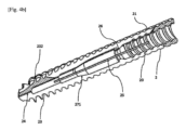
図1a、図1b及び図2は、骨インプラントの例示的かつ非限定的な例示的実施形態である。 Figures 1a, 1b and 2 are illustrative and non-limiting exemplary embodiments of bone implants.
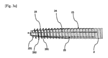
例えば、図1a、図1b、及び図2に示されるように、骨組織内に植え込むことができる骨インプラントは、近位部分(22)と遠位部分(23)との間に延びている拡張可能なスリーブ(2)を備え、これらの2つの部分は長手方向軸(L)を画定し、拡張可能なスリーブは、一方では、拡張可能なスリーブ(2)の内側に少なくとも第1のねじ山(20)を、他方では、拡張可能なスリーブ(2)の外側に少なくとも第2のねじ山(21)を備える。 For example, as shown in Figures 1a, 1b and 2, a bone implant that can be implanted in bone tissue comprises an expandable sleeve (2) extending between a proximal portion (22) and a distal portion (23), these two portions defining a longitudinal axis (L), the expandable sleeve comprising, on the one hand, at least a first thread (20) on the inside of the expandable sleeve (2) and, on the other hand, at least a second thread (21) on the outside of the expandable sleeve (2).
「近位」及び「遠位」という用語は、本出願では、植え込みデバイスが保持されて骨組織内の植え込みを可能にする部分、及び骨組織内に最初に植え込まれる部分(近位部分の反対側)をそれぞれ指す。 The terms "proximal" and "distal" are used in this application to refer to the portion of the implant device that is held to allow implantation in bone tissue and the portion that is initially implanted in bone tissue (opposite the proximal portion), respectively.
「近位部分及び遠位部分」という用語は、本出願では、遠位端及び近位端の近くに位置する部分を指す。 The terms "proximal portion and distal portion" in this application refer to portions located near the distal and proximal ends.
本出願では、「拡張可能なスリーブ(2)」という用語は、概して、中空の一般的な円筒を示す。 In this application, the term "expandable sleeve (2)" generally refers to a hollow, generally cylindrical object.
いくつかの実施形態では、骨インプラントはまた、軸(L)と同一直線上にある軸上で近位部分(12)と遠位部分(13)との間に延びているねじ(1)であって、一方では、長手方向軸(L)に沿って、拡張可能なスリーブ(2)の内側プロファイルと相補的な外側プロファイルを有し、他方では、ねじピッチが拡張可能なスリーブ(2)の第2の外側ねじ山(21)に対して逆になっている、少なくとも1つの外側ねじ山(11)を有する、ねじ(1)、を備える。 In some embodiments, the bone implant also comprises a screw (1) extending between the proximal portion (12) and the distal portion (13) on an axis collinear with the axis (L), the screw (1) having, on the one hand, an outer profile complementary to the inner profile of the expandable sleeve (2) along the longitudinal axis (L) and, on the other hand, at least one outer thread (11) whose thread pitch is reversed relative to the second outer thread (21) of the expandable sleeve (2).
ねじ(1)の近位部分(12)は、皮質骨に直接植え込まれることに留意されたい。 Note that the proximal portion (12) of the screw (1) is implanted directly into the cortical bone.
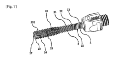
いくつかの実施形態では、ねじ(1)の近位端は、ねじ(1)をねじ込むことを可能にする作動手段を備え、当該作動手段は、例えば、図1bに示されるように、その使用に応じて、施術者にとって望ましい任意の形状の構造を有する。作動手段は、例えば六角形の穴又はトルクス又は十字形又は任意の他の作動手段であり、ねじ(1)の近位端は、骨固定インプラントの望ましい目的場所に応じて様々な形状(多軸若しくは非多軸骨接合バーを固定するため、又はプレート若しくは任意の他のデバイスを固定するためのヘッド)を有し得る。 In some embodiments, the proximal end of the screw (1) is provided with an actuation means that allows the screw (1) to be screwed in, said actuation means having any shape structure desired by the practitioner depending on its use, for example as shown in FIG. 1b. The actuation means is for example a hexagonal hole or a torx or a cross or any other actuation means, and the proximal end of the screw (1) can have various shapes (heads for fixing polyaxial or non-polyaxial osteosynthesis bars, or for fixing plates or any other device) depending on the desired destination of the bone fixation implant.
いくつかの実施形態では、ねじ(1)は、施術者が必要に応じて、例えばセメントを注入することを可能にする、ねじ(1)を通るカニューレを備える。 In some embodiments, the screw (1) includes a cannula passing through the screw (1) that allows the practitioner to, for example, inject cement, if desired.
骨インプラントは、チタンもしくは植え込み可能な医療用ステンレス鋼、又はポリエーテルエーテルケトン(PEEK)、又はポリエーテルケトンケトン(PEKK)、あるいは当業者がその機械的及び物理化学的特性並びに生体適合性に応じて適合性を判断することができる任意の他の材料で作製されていることに留意されたい。 It should be noted that the bone implants are made of titanium or implantable medical grade stainless steel, or polyetheretherketone (PEEK), or polyetherketoneketone (PEKK), or any other material whose suitability can be determined by a person skilled in the art depending on its mechanical and physicochemical properties as well as biocompatibility.
いくつかの実施形態では、ねじ(1)は、施術者が必要に応じて、例えばセメントを注入することを可能にする、ねじ(1)を通るカニューレを備える。 In some embodiments, the screw (1) includes a cannula passing through the screw (1) that allows the practitioner to, for example, inject cement, if desired.
いくつかの実施形態では、拡張可能なスリーブ(2)の外側の第2のねじ山(21)は、骨の固定を可能にする。本出願で使用される「骨固定」という用語は、一般的に反復的なねじ込み動作、衝撃、又は打撃の形態の押圧作用下で、直線経路に沿って骨組織内に入ることを意図した少なくとも1つの要素を含む様々なタイプのデバイスを示す。骨固定ねじは、より良好な固定を確実にするために、一般に機械的ねじよりも高いねじ山の高さを有することが知られている。加えて、骨固定ねじは、一般に機械的ねじとは異なり、当業者であれば、骨の種類及び所望の用途に応じて、コアの直径、ねじピッチ、及びワイヤ高さを変化させることが可能であり、本出願はこれらの様々な実施形態を包含する。拡張可能なスリーブ(2)の第2の外側ねじ山(21)のねじ山高さは、拡張可能なスリーブ(2)の内側の第1のねじ山(20)及びねじ(1)の外側ねじ山(11)の機械的ねじのねじ山高さよりも大きい。したがって、第2のねじ山(21)は、第1のねじ山(20)よりも高い縁部を有し、骨インプラントが骨内に入り、固定されることを可能にする。 In some embodiments, the second external thread (21) of the expandable sleeve (2) allows for bone fixation. The term "bone fixation" as used in this application refers to various types of devices including at least one element intended to enter bone tissue along a linear path, generally under a pressing action in the form of a repetitive screwing action, impact, or blow. It is known that bone fixation screws generally have a higher thread height than mechanical screws to ensure better fixation. In addition, bone fixation screws are generally different from mechanical screws, and the skilled person can vary the core diameter, thread pitch, and wire height depending on the type of bone and the desired application, and this application encompasses these various embodiments. The thread height of the second external thread (21) of the expandable sleeve (2) is greater than the thread height of the mechanical thread of the first internal thread (20) of the expandable sleeve (2) and the external thread (11) of the screw (1). Thus, the second thread (21) has a higher edge than the first thread (20), allowing the bone implant to enter and be fixed in the bone.
更に、いくつかの実施形態では、台形ねじなどのいくつかの機械的ねじは、抵抗がより少なく、骨内に固定された拡張可能なスリーブ(2)へのねじ(1)の貫通を容易にする。台形ねじはまた、骨インプラントに対する圧迫下で骨組織の大きな負荷を分配することを可能にする。 Furthermore, in some embodiments, some mechanical threads, such as trapezoidal threads, provide less resistance and facilitate the penetration of the screw (1) into the expandable sleeve (2) fixed in the bone. The trapezoidal thread also allows for the distribution of large loads of bone tissue under compression against the bone implant.
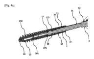
いくつかの実施形態では、拡張可能なスリーブ(2)の遠位部分(23)は、例えば、図1a~図4bに示されるように、拡張可能なスリーブ(2)が骨内に深く埋め込まれることを可能にする円錐状のコアを有するねじ山(232)を備えた円錐台形部分(291)を有する。 In some embodiments, the distal portion (23) of the expandable sleeve (2) has a frusto-conical portion (291) with threads (232) having a conical core that allows the expandable sleeve (2) to be embedded deep within the bone, as shown, for example, in Figures 1a-4b.
いくつかの実施形態では、スリーブ(2)の遠位部分(23)は、セルフタッピングであり、例えば、図3a~図4bに示されるように、セルフタッピング(ミリング及びタッピング)ノッチ(231)を含む。この遠位部分(23)は、インプラントの挿入前に事前に穴を開けることを回避して植え込み中に骨を保つことを可能にし、よって、植え込まれた領域の周りに最大量の骨を保持することができ、骨インプラントの安定性を向上させる。事実、骨統合の時間が短縮され、合成又は天然にかかわらず、任意のタイプの骨充填材料を追加する必要性を抑える。加えて、ノッチ(231)の分布が、遠位部分(23)の部分の各々にわたって良好なバランスを確保することによって、骨組織内へのインプラントの挿入中の力分布の良好な均一性を保証する。 In some embodiments, the distal portion (23) of the sleeve (2) is self-tapping and includes a self-tapping (milling and tapping) notch (231), for example as shown in Figs. 3a-4b. This distal portion (23) allows to preserve bone during implantation by avoiding pre-drilling holes before the insertion of the implant, thus allowing to retain a maximum amount of bone around the implanted area and improving the stability of the bone implant. In effect, the time of osseointegration is reduced and the need to add any type of bone filler material, whether synthetic or natural. In addition, the distribution of the notches (231) ensures a good balance over each of the parts of the distal portion (23), thereby ensuring a good uniformity of the force distribution during the insertion of the implant into the bone tissue.
いくつかの実施形態では、ねじ(1)は、例えば、図2に示されるように、拡張可能なスリーブ(2)へのねじ(1)のねじ込みが、骨組織内への拡張可能なスリーブ(2)のねじ込みと反対方向に実行されなければならない時点を視覚化するために、少なくとも1つの距離マーカ(16)を備える。 In some embodiments, the screw (1) comprises at least one distance marker (16) for visualizing the point at which the screwing of the screw (1) into the expandable sleeve (2) must be performed in the opposite direction to the screwing of the expandable sleeve (2) into the bone tissue, as shown, for example, in FIG. 2.
いくつかの実施形態では、距離マーカ(16)は、レーザマーカである。 In some embodiments, the distance marker (16) is a laser marker.
いくつかの実施形態では、インプラントを配置することは、以下の
距離マーカ(16)が骨皮質の表面と面一になるまで、骨インプラントを外側ねじ山(21)の方向にねじ込む工程と、
骨インプラントを第2のねじ山(11)の方向にねじ込んで、ねじ付きねじ(1)の骨内へのねじ込みを完了し、拡張可能なスリーブ(2)の拡張を進める工程と、を含む。
In some embodiments, placing the implant comprises the steps of: threading the bone implant in the direction of the outer thread (21) until the distance marker (16) is flush with the cortical bone surface;
and screwing the bone implant in the direction of the second thread (11) to complete the screwing of the threaded screw (1) into the bone and to proceed with the expansion of the expandable sleeve (2).
本発明のいくつかの変形例では、皮質骨は、皮質プレフォームツールによって穿孔される。 In some variations of the present invention, the cortical bone is drilled with a cortical preform tool.
本出願はまた、骨組織内における骨インプラントの拡張に関する。 The present application also relates to the expansion of bone implants within bone tissue.
いくつかの実施形態では、ねじ(1)の外側プロファイルと拡張可能なスリーブ(2)の内側プロファイルは相補的であり、それにより、それらのプロファイルが、拡張構成において、
拡張可能なスリーブ(2)の内径とねじ(1)の外径の相補性によって支持される近位支承部と、
拡張可能なスリーブの内径がねじ(1)の外径よりも小さくなるまで、遠位部分に向かって狭くなっている、拡張可能なスリーブ(2)とねじ(1)との協働によって支持される遠位支承部と、
2つの支承部の間に位置する「中央」支承部であって、ねじ(1)の外径と拡張可能なスリーブ(2)の内径との間の協働によって形成され、それにより「中央」位置での拡張可能なスリーブ(2)の外径を、近位支承部における拡張可能なスリーブ(2)の外径よりも大きくさせる、「中央」支承部と、をもたらす。
In some embodiments, the outer profile of the screw (1) and the inner profile of the expandable sleeve (2) are complementary, such that in the expanded configuration,
a proximal bearing supported by the complementarity of the inner diameter of the expandable sleeve (2) and the outer diameter of the screw (1);
a distal bearing supported by the cooperation of the expandable sleeve (2) and the screw (1), the inner diameter of which narrows towards the distal portion until the inner diameter of the expandable sleeve is smaller than the outer diameter of the screw (1);
and a "central" bearing located between the two bearings and formed by cooperation between the outer diameter of the screw (1) and the inner diameter of the expandable sleeve (2), thereby causing the outer diameter of the expandable sleeve (2) at the "central" position to be larger than the outer diameter of the expandable sleeve (2) at the proximal bearing.
いくつかの実施形態では、例えば、図4a及び図4bに示されるように、インプラントは、ねじ(1)を拡張可能なスリーブ(2)に貫通させ、かつ、ねじ(1)の外径が、遠位部分において少なくとも1つの収縮部(271)によって拡張可能なスリーブ(2)の内径よりも大きいという事実に起因して、変形によって拡張可能なスリーブ(2)を拡張させることによって、逆のねじ山の作動により、折り畳まれた静止位置から展開した位置に切り替えることができる。 In some embodiments, as shown, for example, in Figures 4a and 4b, the implant can be switched from a folded rest position to a deployed position by actuation of the reverse threads, by passing the screw (1) through the expandable sleeve (2) and expanding the expandable sleeve (2) by deformation due to the fact that the outer diameter of the screw (1) is larger than the inner diameter of the expandable sleeve (2) by at least one constriction (271) in the distal portion.
いくつかの実施形態では、収縮部(271)は、近位部分に対して、かつ、長手方向軸(L)に沿って、拡張が所望される骨組織内の深さに応じて決定された距離に位置する。当該距離は、例えば、図4a及び図4bに示されるように、骨皮質及び/又は所望の圧迫に関して特に、施術者自身によって決定されることに留意されたい。 In some embodiments, the constriction (271) is located at a distance relative to the proximal portion and along the longitudinal axis (L) that is determined according to the depth into the bone tissue to which expansion is desired. Note that the distance is determined by the practitioner himself, particularly with respect to the bone cortex and/or the desired compression, e.g., as shown in Figures 4a and 4b.
いくつかの実施形態では、拡張可能なスリーブ(2)の近位端と遠位端との間の中間部分のダクトは、中央支承部が位置する場所の径よりも大きい、直径差を有する。 In some embodiments, the duct in the middle portion between the proximal and distal ends of the expandable sleeve (2) has a diameter difference that is greater than the diameter where the central support is located.
いくつかの実施形態では、近位端と遠位端との間の中間部分の拡張可能なスリーブ(2)のダクトは、非連続的な勾配を有する。したがって、収縮部(271)は、例えば、骨のタイプに応じて近位端からの可変距離に位置して、様々な深さで拡張を提供することができる。 In some embodiments, the duct of the expandable sleeve (2) in the intermediate portion between the proximal and distal ends has a discontinuous gradient. Thus, the constriction (271) can be located at variable distances from the proximal end depending on, for example, the bone type, to provide expansion at various depths.
いくつかの実施形態では、ねじ(1)の近位部分は、例えば、図1a、図1b及び図2に示されるように、外側骨固定ねじ山(15)を含む。 In some embodiments, the proximal portion of the screw (1) includes an external bone fixation thread (15), as shown, for example, in Figures 1a, 1b, and 2.
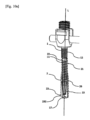
いくつかの実施形態では、ねじ(1)は、拡張可能なスリーブ(2)の内部に埋め込むことによって骨組織内に植え込まれるように構成されており、外側骨固定ねじ山(15)を含むねじ(1)の近位部分は、骨組織内に植え込まれるように適合されており、例えば、図11に示されるように、展開した位置における拡張可能なスリーブ(2)の近位部分の広がりに対して逆に広がる円錐台形部分を有する。この2つの円錐台の広がりの逆転は、特にこれら2つの円錐台が骨皮質の周囲に位置するという事実に起因して、インプラントの安定性を改善する圧迫及び/又は摩擦を必要とする。 In some embodiments, the screw (1) is configured to be implanted in bone tissue by embedding it inside the expandable sleeve (2), and the proximal part of the screw (1) including the outer bone anchoring thread (15) is adapted to be implanted in bone tissue and has a frustoconical part that is inversely divergent to the divergence of the proximal part of the expandable sleeve (2) in the deployed position, as shown, for example, in FIG. 11. This reversal of the divergence of the two frustums requires compression and/or friction that improves the stability of the implant, especially due to the fact that these two frustums are located around the bone cortex.
いくつかの実施形態では、ねじ(1)は、拡張可能なスリーブ(2)の内部に埋め込むことによって骨組織内に植え込まれるように構成されており、外側骨固定ねじ山(15)を含むねじ(1)の近位部分は、骨組織内に植え込まれるように適合されており、円筒形部分又は任意のオフセット形状を有する。 In some embodiments, the screw (1) is configured to be implanted in bone tissue by embedding it inside the expandable sleeve (2), and the proximal portion of the screw (1) including the outer bone anchoring thread (15) is adapted to be implanted in bone tissue and has a cylindrical portion or any offset shape.
得られた反対の逆転二重円錐台は、植え込み中に骨組織内に骨インプラントの力を分配することによってインプラントの漸進的な植え込みを可能にし、円筒形の線上ではなく円錐表面上の力の伝達を可能にする。更に、反対の逆転二重円錐台は、最も密度の高い椎骨の皮質部分に対する軸方向の係止を確実にする。したがって、骨組織における骨インプラントの非常に高い安定性に寄与する。 The resulting opposing inverted double truncated cone allows for gradual implantation of the implant by distributing the forces of the bone implant in the bone tissue during implantation, allowing the transmission of forces on a conical surface rather than on a cylindrical line. Furthermore, the opposing inverted double truncated cone ensures axial locking against the densest cortical part of the vertebrae, thus contributing to a very high stability of the bone implant in the bone tissue.
いくつかの実施形態では、例えば、図3aに示されるように、拡張可能なスリーブ(2)は、遠位部分(23)の端部に鋭角αを有する。この角度αは、拡張中にねじ(1)が拡張可能なスリーブ(2)に入るにつれて広がり増大する。 In some embodiments, for example as shown in FIG. 3a, the expandable sleeve (2) has an acute angle α at the end of the distal portion (23). This angle α widens and increases as the screw (1) enters the expandable sleeve (2) during expansion.
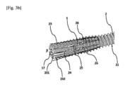
いくつかの実施形態では、例えば、図3bに示されるように、角度αは、拡張中に漸増的広がり角度βになり、角度βは、拡張した拡張可能なスリーブ(2)の角度である。 In some embodiments, for example as shown in FIG. 3b, the angle α becomes an incremental spread angle β during expansion, where the angle β is the angle of the expanded expandable sleeve (2).
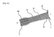
いくつかの実施形態では、例えば、図3cに示されるように、皮質部分は、骨インプラントを圧迫し、皮質部分は、拡張可能なスリーブ(2)、又はねじ(1)、又はその両方によって保持される角度γを有する。角度αは、次第に広がることによって、拡張可能なスリーブ(2)の角度βになり、角度γに対向する。 In some embodiments, for example as shown in FIG. 3c, the cortical portion bears against the bone implant and has an angle γ that is held by the expandable sleeve (2), or the screw (1), or both. The angle α widens to become the angle β of the expandable sleeve (2) and opposes the angle γ.
展開した位置では、拡張可能なスリーブ(2)の壁は、いくつかの実施形態では、角度βをなす代わりに平行であり得ることに留意されたい。 Note that in the deployed position, the walls of the expandable sleeve (2) may be parallel instead of at an angle β in some embodiments.
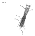
いくつかの実施形態では、拡張可能なスリーブ(2)は、角度α及びβの存在によって、例えば図5に示されるように、中央支承部にドーム形状を有する。 In some embodiments, the expandable sleeve (2) has a dome shape at the central bearing due to the presence of angles α and β, as shown, for example, in FIG. 5.
実際には、いくつかの実施形態では、インプラントは、例えば、図1a、図1b、図4a、図4b、図6、及び図8~図10に示されるように、一方では、当接機構(26)が、拡張可能なスリーブ(2)とねじ本体(1)とをこれらの2つのそれぞれのねじピッチの逆転により噛み合わせる静止構成と、他方では、拡張可能なスリーブ(2)とねじ(1)の相補的な内側ねじ山及び外側ねじ山を相互に作動し、ねじ(1)を拡張可能なスリーブ(2)に貫通させ、ねじ(1)の拡張可能なスリーブ(2)への貫通中に、拡張可能なスリーブ(2)の内径よりも大きいねじ(1)の外径により、拡張可能なスリーブ(2)の変形によって少なくとも遠位部分において拡張可能なスリーブ(2)の拡張を生じさせることによって得られる拡張構成と、の間で拡張可能である。 In fact, in some embodiments, the implant is expandable between, on the one hand, a static configuration in which the abutment mechanism (26) engages the expandable sleeve (2) and the screw body (1) by reversing their two respective thread pitches, as shown, for example, in Figs. 1a, 1b, 4a, 4b, 6, and 8-10, and, on the other hand, an expanded configuration obtained by mutually actuating the complementary internal and external threads of the expandable sleeve (2) and the screw (1), penetrating the screw (1) into the expandable sleeve (2) and, during the penetration of the screw (1) into the expandable sleeve (2), causing an expansion of the expandable sleeve (2) at least in its distal portion by deformation of the expandable sleeve (2) due to the outer diameter of the screw (1) being larger than the inner diameter of the expandable sleeve (2).
いくつかの実施形態では、インプラントの展開した位置において、拡張可能なスリーブ(2)の第2の遠位径は、スリーブ(2)の第1の近位径以上であるため、スリーブ(2)は、拡張によって得られた円筒形状又は円錐台形部分を有する。 In some embodiments, in the deployed position of the implant, the second distal diameter of the expandable sleeve (2) is equal to or greater than the first proximal diameter of the sleeve (2), such that the sleeve (2) has a cylindrical or frustoconical portion obtained by expansion.
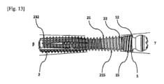
インプラントは、展開した位置においてインプラントの近位部分の近くに、近位部分に向かって広がる近位円錐台形部分を有し、この近位円錐台形部分は、
例えば、図3cに示されるように、拡張可能なスリーブ(2)によって角度γが保持されるモードにおいて、拡張可能なスリーブ(2)の外側プロファイルによって、
又は、例えば、図5に示されるように、ねじ(1)によって角度γが保持されるモードにおいて、ねじ本体(1)の外側プロファイルによって、
又は、例えば、図13に示されるように、ねじ(1)及び拡張可能スリーブ(2)によって角度γが保持されるモードにおいて、展開した位置において、スリーブ(2)及びねじ本体(1)の外側プロファイルの相補的な形状によって、
のいずれかで、形成される。
The implant has a proximal frustoconical portion near a proximal portion of the implant in the deployed position that flares toward the proximal portion, the proximal frustoconical portion having a diameter of:
For example, in a mode in which the angle γ is maintained by the expandable sleeve (2), as shown in FIG. 3c, the outer profile of the expandable sleeve (2)
Or, for example, in the mode in which the angle γ is held by the screw (1), as shown in FIG. 5, the outer profile of the screw body (1)
Or, for example, in a mode in which the angle γ is maintained by the screw (1) and the expandable sleeve (2), as shown in FIG. 13, in the deployed position, due to the complementary shapes of the outer profiles of the sleeve (2) and the screw body (1):
It is formed by either
当該近位円錐台形部分は、その周囲に外側骨固定ねじ山(15、215)を有する。 The proximal frustoconical portion has an external bone fixation thread (15, 215) around its periphery.
いくつかの実施形態では、インプラントの展開した位置において、拡張可能なスリーブ(2)は、例えば、図5~図10bに示されるように、少なくとも1つの近位部分(22)に円錐台形状を有し、ねじ(1)の近位部分の近くでねじ(1)の遠位部分に向かって広がる。 In some embodiments, in the deployed position of the implant, the expandable sleeve (2) has a frusto-conical shape in at least one proximal portion (22) and widens near the proximal portion of the screw (1) toward the distal portion of the screw (1), as shown, for example, in Figures 5-10b.
いくつかの実施形態では、拡張可能なスリーブ(2)は、少なくとも1つの近位部分(22)に円筒形状又は円錐形状を有する。 In some embodiments, the expandable sleeve (2) has a cylindrical or conical shape in at least one proximal portion (22).
いくつかの実施形態では、ねじ(1)は、例えば、図1a、図1b、図2、図5、図10a、図10b、及び図12に示されるように、遠位部分(13)の先端に先端(17)を備え、その外側プロファイルは、拡張可能なスリーブ(2)の遠位部分(23)の内側プロファイルと相補的である。 In some embodiments, the screw (1) has a tip (17) at the tip of the distal portion (13) whose outer profile is complementary to the inner profile of the distal portion (23) of the expandable sleeve (2), as shown, for example, in Figures 1a, 1b, 2, 5, 10a, 10b, and 12.
いくつかの実施形態では、拡張可能なスリーブ(2)の近位部分の円錐台形部分とねじ(1)の円錐台形外側プロファイルは、互いに端部同士で接して、又は互いに対向して配置されて、拡張可能なスリーブ(2)の近位部分(22)に接続され、拡張可能なスリーブ(2)の近位部分の円錐台形部分の角度は、ねじ(1)の当該円錐台形外側プロファイルの角度よりも大きく、より大きな広がりを可能にする、及び/又は全体の拡張を容易にする。 In some embodiments, the frustoconical portion of the proximal portion of the expandable sleeve (2) and the frustoconical outer profile of the screw (1) are connected to the proximal portion (22) of the expandable sleeve (2) end-to-end or facing each other, and the angle of the frustoconical portion of the proximal portion of the expandable sleeve (2) is greater than the angle of the frustoconical outer profile of the screw (1), allowing for greater expansion and/or facilitating overall expansion.
いくつかの実施形態では、例えば、図2、図3、図5、図6、図7、図8に示されるように、拡張可能なスリーブ(2)は、その遠位部分(23)まで延びている長手方向貫通スロット(24)と、拡張可能なスリーブ(2)の拡張を可能にする長手方向非貫通スロット(25)と、を含む。いくつかの貫通スロット(24)又は非貫通スロット(25)が存在し、遠位部分(23)が、2つのタイプのスロット、すなわち、長手方向貫通スロット(24)及び長手方向非貫通スロット(25)を含むことが好ましい。 In some embodiments, for example as shown in Figures 2, 3, 5, 6, 7, 8, the expandable sleeve (2) includes longitudinal through slots (24) extending to its distal portion (23) and longitudinal non-through slots (25) that allow the expansion of the expandable sleeve (2). It is preferred that there are several through slots (24) or non-through slots (25) and that the distal portion (23) includes two types of slots, i.e. longitudinal through slots (24) and longitudinal non-through slots (25).
いくつかの実施形態では、貫通スロット(24)と非貫通スロット(25)との間の相乗作用はまた、展開した位置において円錐台形状及び/又はドーム形状を可能にする。 In some embodiments, the synergy between the through slots (24) and the non-through slots (25) also allows for a frusto-conical and/or dome shape in the deployed position.
いくつかの実施形態では、長手方向貫通スロット(24)と同数のセルフタッピングノッチ(231)が存在する。 In some embodiments, there are as many self-tapping notches (231) as there are longitudinal through slots (24).
いくつかの実施形態では、貫通スロット(24)と非貫通スロット(25)とは、拡張可能なスリーブ(2)の長さにわたって互いに対してオフセットされて配置されている。長さにわたる、貫通スロット(24)と非貫通スロット(25)とのオフセットは、拡張中の拡張可能なスリーブ(2)の柔軟性及び機械的強度を改善する。 In some embodiments, the through slots (24) and the non-through slots (25) are offset relative to one another over the length of the expandable sleeve (2). The offset of the through slots (24) and the non-through slots (25) over the length improves the flexibility and mechanical strength of the expandable sleeve (2) during expansion.
本発明のいくつかの変形例では、骨固定部(15、215)の伸長が可能である。 In some variations of the present invention, the bone fixation portion (15, 215) can be extended.
いくつかの実施形態では、遠位部分(23)の長手方向貫通スロット(24)及び非貫通スロット(25)は、拡張可能なスリーブ(2)の円筒形の拡張を可能にする。長手方向非貫通スロット(25)は、拡張中に、拡張可能なスリーブ(2)とねじ(1)との間の3つの支承部上の接触プロファイルを維持することを可能にし、拡張による力を、拡張した拡張可能なスリーブ(2)の外周にわたって均一に分布させることによって、骨組織内の骨インプラントの安定性に寄与する。長手方向貫通スロット(24)及び非貫通スロット(25)は、拡張可能なスリーブ(2)の材料の弾性限界と、ねじを緩める間のその弾性収縮とに対応することによって、拡張可能なスリーブ(2)の近位部分(22)の径方向の拡張を可能にする。 In some embodiments, the longitudinal through slots (24) and the non-through slots (25) of the distal portion (23) allow for cylindrical expansion of the expandable sleeve (2). The longitudinal non-through slots (25) allow for maintaining a contact profile on three bearings between the expandable sleeve (2) and the screw (1) during expansion, contributing to the stability of the bone implant in the bone tissue by distributing the expansion forces evenly over the circumference of the expanded expandable sleeve (2). The longitudinal through slots (24) and the non-through slots (25) allow for radial expansion of the proximal portion (22) of the expandable sleeve (2) by accommodating the elastic limit of the material of the expandable sleeve (2) and its elastic contraction during unscrewing.
いくつかの実施形態では、前記長手方向貫通スロット(24)は、拡張可能なスリーブ(2)の長さの10~90%にわたって延びている。 In some embodiments, the longitudinal through slot (24) extends over 10-90% of the length of the expandable sleeve (2).
いくつかの実施形態では、例えば、図3aに示されるように、拡張可能なスリーブ(2)の部分は、ねじの底部にテーパ角度アルファ(α)を含み、拡張可能なスリーブ(2)の形状により、ねじ込み動作中に、解剖学的円錐プリフォームツールによって形成される空洞内での拡張可能なスリーブ(2)の自動センタリングを確実にする。 In some embodiments, for example as shown in FIG. 3a, a portion of the expandable sleeve (2) includes a taper angle alpha (α) at the bottom of the thread, and the shape of the expandable sleeve (2) ensures self-centering of the expandable sleeve (2) within the cavity formed by the anatomical conical preform tool during the threading operation.
1つの代替的な実施形態(図示せず)によれば、ねじ(1)は、皮質ねじ部を含まない。この変形例は、他の植え込み状況に適合した、より短いねじ(1)と拡張可能なスリーブ(2)とのアセンブリを作製することを可能にする。 According to one alternative embodiment (not shown), the screw (1) does not include a cortical thread portion. This variation makes it possible to create shorter screw (1) and expandable sleeve (2) assemblies adapted to other implantation situations.
当業者であれば、この目的のために、及びインプラントの目的に従って、この部分の形状を適合させることによる他のアセンブリモードに従って、様々なタイプの先端及び構造体をねじ(1)の近位部分に追加することができると理解するであろう。非限定的な例として、これらのアセンブリは、ねじ、クリップ留め、キー締め、接合、又は溶接によって作製することができる。 A person skilled in the art will understand that for this purpose, and according to other assembly modes by adapting the shape of this part according to the purpose of the implant, various types of tips and structures can be added to the proximal part of the screw (1). As non-limiting examples, these assemblies can be made by screwing, clipping, keying, bonding or welding.
したがって、本発明で提案された骨インプラントは、骨組織内に迅速かつ正確に植え込まれ、骨組織において植え込まれた状態を非常に安定した様式で保ち得る。 The bone implant proposed in the present invention can therefore be rapidly and precisely implanted in bone tissue and remain implanted in the bone tissue in a very stable manner.
本出願は、図面及び/又は様々な実施形態を参照して様々な技術的特徴及び利点を説明している。当業者であれば、反すると明示的に述べられない、又はこれらの特性が不適合である、又は組み合わせが機能しない限り、実際に、所与の実施形態の技術的特徴が1つ以上の他の実施形態の特徴と組み合わせることができることを理解するであろう。 This application describes various technical features and advantages with reference to drawings and/or various embodiments. Those skilled in the art will appreciate that, in fact, the technical features of a given embodiment may be combined with the features of one or more other embodiments, unless expressly stated to the contrary, or unless those features are incompatible or the combination is inoperative.
より一般的には、様々なタイプのインプラント保持手段及び/又は脊椎保持手段の組み合わせが想定され、本出願で提供される機能的及び構造的考察を使用して当業者によって理解されるであろう。更に、特に、本出願で提供される機能的考察は、必要とされ得る構造的適合が当業者の実行範囲内にあるように十分な説明を提供するものであるため、所与の実施形態に記載されている技術的特徴は、反すると明示的に述べられない限り、このモードの他の特徴から分離することができる。 More generally, combinations of various types of implant retention means and/or spinal retention means are contemplated and will be understood by those skilled in the art using the functional and structural considerations provided in this application. Moreover, technical features described in a given embodiment may be separated from other features of this mode unless expressly stated to the contrary, particularly since the functional considerations provided in this application provide sufficient description such that structural adaptations that may be required are within the scope of practice of the skilled artisan.
当業者は、本出願を読めば、特許請求される本発明の適用範囲から逸脱することなく、詳細に説明されるもの以外の多くの特定の形態の実施形態が可能であることを理解するであろう。したがって、本実施形態は、例示として考慮されるべきであるが、添付の特許請求の範囲によって定義される分野において修正することができ、本発明は、上記の詳細に限定されるべきではない。 Those skilled in the art will understand, upon reading this application, that many specific forms of embodiment other than those specifically described are possible without departing from the scope of the invention as claimed. The present embodiment should therefore be considered as an example, but can be modified in the field defined by the appended claims, and the invention should not be limited to the above details.
Claims (14)
第1の内径を有する近位部分(22)と、前記第1の内径よりも小さい第2の内径を有する遠位部分(23)との間に延びている拡張可能なスリーブ(2)であって、前記2つの部分が長手方向軸(L)を画定し、前記第1及び第2の内径が前記拡張可能なスリーブ(2)の内側プロファイルを画定し、前記拡張可能なスリーブ(2)が、一方では、前記拡張可能なスリーブ(2)の内側に少なくとも第1のねじ山(20)を、他方では、前記拡張可能なスリーブ(2)の外側に少なくとも第2のねじ山(21)を備える、拡張可能なスリーブ(2)と、
近位部分(12)と遠位部分(13)との間に延びているねじ本体(1)であって、一方では、前記長手方向軸(L)に沿って、前記拡張可能なスリーブ(2)の前記内側プロファイルと相補的な外側プロファイルを有し、他方では、ねじピッチが前記拡張可能なスリーブ(2)の前記第2の外側ねじ山(21)に対して逆になっている、少なくとも1つの外側ねじ山(11)を有する、ねじ本体(1)と、を備え、
前記インプラントは、前記ねじ(1)を前記拡張可能なスリーブ(2)内に貫通させ、かつ、前記ねじ(1)の外径が、少なくとも遠位部分で、少なくとも1つの収縮部(271)によって前記拡張可能なスリーブ(2)の前記第2の内径よりも大きいという事実に起因して、変形によって前記拡張可能なスリーブ(2)を拡張させることによって、前記逆のねじの作動により、折り畳まれた静止位置から展開した位置に切り替えることができ、
前記インプラントの前記展開した位置では、前記拡張可能なスリーブ(2)の前記第2の内径が、前記スリーブの前記第1の近位径以上である、
皮質安定化を伴う骨固定インプラントにおいて、
前記スリーブは、前記拡張によって得られた円筒形状又は円錐台形部分を有し、
前記インプラントは、前記展開した位置において前記インプラントの前記近位部分の近くに、前記近位部分に向かって広がる近位円錐台形部分を有し、前記近位円錐台形部分は、
前記スリーブ(2)の前記外側プロファイルによって、
又は前記ねじ本体(1)の前記外側プロファイルによって、
又は前記展開した位置における前記スリーブ(2)及び前記ねじ本体(1)の前記外側プロファイルの相補的な形状によって、
のいずれかで、形成され、
前記近位円錐台形部分が、その周囲に外側骨固定ねじ山(15、252)を有する、ことを特徴とする、骨固定インプラント。 1. A bone fixation implant with cortical stabilization that can be implanted in fixation tissue, comprising:
an expandable sleeve (2) extending between a proximal portion (22) having a first inner diameter and a distal portion (23) having a second inner diameter smaller than said first inner diameter, said two portions defining a longitudinal axis (L), said first and second inner diameters defining an inner profile of said expandable sleeve (2), said expandable sleeve (2) comprising, on the one hand, at least a first thread (20) on the inside of said expandable sleeve (2) and, on the other hand, at least a second thread (21) on the outside of said expandable sleeve (2);
a screw body (1) extending between a proximal portion (12) and a distal portion (13), the screw body (1) having, on the one hand, an external profile along the longitudinal axis (L) complementary to the internal profile of the expandable sleeve (2) and, on the other hand, at least one external thread (11) whose thread pitch is reversed relative to the second external thread (21) of the expandable sleeve (2),
said implant can be switched from a folded rest position to a deployed position by actuation of said reverse screw by penetrating said screw (1) into said expandable sleeve (2) and expanding said expandable sleeve (2) by deformation due to the fact that the outer diameter of said screw (1), at least in its distal part, is greater than the second inner diameter of said expandable sleeve (2) by at least one constriction (271);
In the deployed position of the implant, the second inner diameter of the expandable sleeve (2) is equal to or greater than the first proximal diameter of the sleeve.
In bone-anchored implants with cortical stabilization,
the sleeve has a cylindrical or frustoconical portion obtained by the expansion,
The implant has a proximal frustoconical portion adjacent the proximal portion of the implant in the deployed position and flaring toward the proximal portion, the proximal frustoconical portion comprising:
The outer profile of the sleeve (2) provides
or by the outer profile of the screw body (1),
or by the complementary shapes of the outer profiles of the sleeve (2) and the screw body (1) in the deployed position,
Either
A bone anchoring implant, characterized in that said proximal frusto-conical portion has an external bone anchoring thread (15, 252) around its periphery.
Applications Claiming Priority (3)
| Application Number | Priority Date | Filing Date | Title |
|---|---|---|---|
| FR2003579 | 2020-04-09 | ||
| FR2003579A FR3109075B1 (en) | 2020-04-09 | 2020-04-09 | Cortical Stabilization Bone Anchor Implant |
| PCT/EP2021/059195 WO2021204951A1 (en) | 2020-04-09 | 2021-04-08 | Cortically stabilized bone anchoring implant |
Publications (2)
| Publication Number | Publication Date |
|---|---|
| JP2023521374A JP2023521374A (en) | 2023-05-24 |
| JP7702425B2 true JP7702425B2 (en) | 2025-07-03 |
Family
ID=72178654
Family Applications (1)
| Application Number | Title | Priority Date | Filing Date |
|---|---|---|---|
| JP2022561472A Active JP7702425B2 (en) | 2020-04-09 | 2021-04-08 | Bone-anchored implants with cortical stabilization |
Country Status (18)
| Country | Link |
|---|---|
| US (2) | US11426224B2 (en) |
| EP (1) | EP4132391B1 (en) |
| JP (1) | JP7702425B2 (en) |
| KR (1) | KR20230025386A (en) |
| CN (1) | CN115916078B (en) |
| AU (1) | AU2021253657B2 (en) |
| BR (1) | BR112022020425A2 (en) |
| CA (1) | CA3179741A1 (en) |
| CO (1) | CO2022015876A2 (en) |
| ES (1) | ES2983030T3 (en) |
| FR (1) | FR3109075B1 (en) |
| IL (1) | IL297119B2 (en) |
| MX (1) | MX2022012612A (en) |
| PL (1) | PL4132391T3 (en) |
| PT (1) | PT4132391T (en) |
| SA (1) | SA522440865B1 (en) |
| WO (1) | WO2021204951A1 (en) |
| ZA (1) | ZA202212027B (en) |
Families Citing this family (3)
| Publication number | Priority date | Publication date | Assignee | Title |
|---|---|---|---|---|
| CN116585018A (en) * | 2023-06-05 | 2023-08-15 | 浙江大学医学院附属邵逸夫医院 | Reinforced medical screw expansion sleeve |
| CN116687540A (en) * | 2023-08-08 | 2023-09-05 | 苏州奥芮济医疗科技有限公司 | A compression degradable bone screw and its manufacturing method |
| WO2026033250A1 (en) * | 2024-08-09 | 2026-02-12 | Filipov Iulian | Device for optimizing the primary stability for dental implants inserted at the same surgical time with the sinus lift procedure |
Citations (3)
| Publication number | Priority date | Publication date | Assignee | Title |
|---|---|---|---|---|
| US20120259372A1 (en) | 2007-01-19 | 2012-10-11 | Pbj, Llc | Orthopedic screw insert |
| JP2014517739A (en) | 2011-04-14 | 2014-07-24 | グローバス メディカル インコーポレイティッド | Expandable spinal anchor |
| CN104095677A (en) | 2014-07-15 | 2014-10-15 | 东南大学 | High-strength combined self-degrading expansion bone peg |
Family Cites Families (10)
| Publication number | Priority date | Publication date | Assignee | Title |
|---|---|---|---|---|
| US5004421A (en) * | 1990-07-27 | 1991-04-02 | Sargon Lazarof | Dental implant and method of using same |
| US5087199A (en) * | 1990-07-27 | 1992-02-11 | Sargon Lazarof | Dental implant and method of using same |
| DE29619163U1 (en) * | 1996-11-07 | 1998-03-05 | Unger, Heinz-Dieter, Dr.med.dent., 49080 Osnabrück | Implant body |
| DE19646307A1 (en) * | 1996-11-09 | 1998-05-14 | Ralf Dr Schroeder | Screw-in jaw implant for tooth inserts and crowns |
| US6668688B2 (en) * | 2001-06-28 | 2003-12-30 | Mayo Foundation | Expandable screw apparatus and method thereof |
| TWM306498U (en) * | 2006-08-10 | 2007-02-21 | Shih-Tseng Lee | Securing member, expansion anchroing screw set |
| FR2965473B1 (en) * | 2010-10-05 | 2013-08-09 | Altade | ENDO-BONE IMPLANT WITH IMPROVED ANCHORAGE |
| US9113972B2 (en) * | 2011-08-24 | 2015-08-25 | Pioneer Surgical Technology, Inc. | Apparatus and methods for immobilization and fusion of a synovial joint |
| US11224467B2 (en) * | 2016-02-26 | 2022-01-18 | Activortho, Inc. | Active compression apparatus, methods of assembly and methods of use |
| CA3015902A1 (en) * | 2016-02-26 | 2017-08-31 | Activortho, Inc. | Active compression apparatus, methods of assembly and methods of use |
-
2020
- 2020-04-09 FR FR2003579A patent/FR3109075B1/en not_active Expired - Fee Related
- 2020-11-10 US US17/093,985 patent/US11426224B2/en active Active
-
2021
- 2021-04-08 IL IL297119A patent/IL297119B2/en unknown
- 2021-04-08 CA CA3179741A patent/CA3179741A1/en active Pending
- 2021-04-08 KR KR1020227038928A patent/KR20230025386A/en active Pending
- 2021-04-08 PT PT217221068T patent/PT4132391T/en unknown
- 2021-04-08 CN CN202180027194.2A patent/CN115916078B/en active Active
- 2021-04-08 ES ES21722106T patent/ES2983030T3/en active Active
- 2021-04-08 AU AU2021253657A patent/AU2021253657B2/en active Active
- 2021-04-08 JP JP2022561472A patent/JP7702425B2/en active Active
- 2021-04-08 PL PL21722106.8T patent/PL4132391T3/en unknown
- 2021-04-08 MX MX2022012612A patent/MX2022012612A/en unknown
- 2021-04-08 WO PCT/EP2021/059195 patent/WO2021204951A1/en not_active Ceased
- 2021-04-08 EP EP21722106.8A patent/EP4132391B1/en active Active
- 2021-04-08 BR BR112022020425A patent/BR112022020425A2/en unknown
-
2022
- 2022-07-22 US US17/871,268 patent/US12558135B2/en active Active
- 2022-10-08 SA SA522440865A patent/SA522440865B1/en unknown
- 2022-11-03 ZA ZA2022/12027A patent/ZA202212027B/en unknown
- 2022-11-03 CO CONC2022/0015876A patent/CO2022015876A2/en unknown
Patent Citations (3)
| Publication number | Priority date | Publication date | Assignee | Title |
|---|---|---|---|---|
| US20120259372A1 (en) | 2007-01-19 | 2012-10-11 | Pbj, Llc | Orthopedic screw insert |
| JP2014517739A (en) | 2011-04-14 | 2014-07-24 | グローバス メディカル インコーポレイティッド | Expandable spinal anchor |
| CN104095677A (en) | 2014-07-15 | 2014-10-15 | 东南大学 | High-strength combined self-degrading expansion bone peg |
Also Published As
| Publication number | Publication date |
|---|---|
| CN115916078A (en) | 2023-04-04 |
| CN115916078B (en) | 2024-04-05 |
| IL297119B1 (en) | 2025-05-01 |
| KR20230025386A (en) | 2023-02-21 |
| US20210315622A1 (en) | 2021-10-14 |
| PL4132391T3 (en) | 2024-07-22 |
| PT4132391T (en) | 2024-06-18 |
| ZA202212027B (en) | 2023-07-26 |
| JP2023521374A (en) | 2023-05-24 |
| FR3109075A1 (en) | 2021-10-15 |
| US12558135B2 (en) | 2026-02-24 |
| IL297119A (en) | 2022-12-01 |
| FR3109075B1 (en) | 2023-06-30 |
| AU2021253657A1 (en) | 2022-11-03 |
| CA3179741A1 (en) | 2021-10-14 |
| BR112022020425A2 (en) | 2022-12-20 |
| MX2022012612A (en) | 2023-02-09 |
| ES2983030T3 (en) | 2024-10-21 |
| AU2021253657B2 (en) | 2026-02-12 |
| CO2022015876A2 (en) | 2023-02-16 |
| US20220354558A1 (en) | 2022-11-10 |
| EP4132391B1 (en) | 2024-03-20 |
| SA522440865B1 (en) | 2024-05-28 |
| US11426224B2 (en) | 2022-08-30 |
| IL297119B2 (en) | 2025-09-01 |
| WO2021204951A1 (en) | 2021-10-14 |
| EP4132391A1 (en) | 2023-02-15 |
Similar Documents
| Publication | Publication Date | Title |
|---|---|---|
| EP3277210B1 (en) | Anti-penetration bone implant device | |
| US10314630B2 (en) | Apparatus and methods for immobilization and fusion of a synovial joint | |
| JP7702425B2 (en) | Bone-anchored implants with cortical stabilization | |
| JP7741813B2 (en) | Bone-anchored implant with optimized expansion | |
| JP2017538546A (en) | Bone screw | |
| JP7646720B2 (en) | Expandable bone core for pedicle screw fixation | |
| CN115916079B (en) | Bone anchoring implant convenient to remove | |
| RU2849408C1 (en) | Bone expandable orthopedic screw | |
| RU2849923C1 (en) | Bone expandable orthopedic screw | |
| RU2850373C1 (en) | Bone expanding orthopedic screw |
Legal Events
| Date | Code | Title | Description |
|---|---|---|---|
| A621 | Written request for application examination |
Free format text: JAPANESE INTERMEDIATE CODE: A621 Effective date: 20240403 |
|
| A131 | Notification of reasons for refusal |
Free format text: JAPANESE INTERMEDIATE CODE: A131 Effective date: 20241120 |
|
| A977 | Report on retrieval |
Free format text: JAPANESE INTERMEDIATE CODE: A971007 Effective date: 20241120 |
|
| TRDD | Decision of grant or rejection written | ||
| A01 | Written decision to grant a patent or to grant a registration (utility model) |
Free format text: JAPANESE INTERMEDIATE CODE: A01 Effective date: 20250529 |
|
| A61 | First payment of annual fees (during grant procedure) |
Free format text: JAPANESE INTERMEDIATE CODE: A61 Effective date: 20250623 |
|
| R150 | Certificate of patent or registration of utility model |
Ref document number: 7702425 Country of ref document: JP Free format text: JAPANESE INTERMEDIATE CODE: R150 |