JP7694246B2 - Arithmetic device, neural network system, neuron model device, arithmetic method, and program - Google Patents
Arithmetic device, neural network system, neuron model device, arithmetic method, and program Download PDFInfo
- Publication number
- JP7694246B2 JP7694246B2 JP2021130005A JP2021130005A JP7694246B2 JP 7694246 B2 JP7694246 B2 JP 7694246B2 JP 2021130005 A JP2021130005 A JP 2021130005A JP 2021130005 A JP2021130005 A JP 2021130005A JP 7694246 B2 JP7694246 B2 JP 7694246B2
- Authority
- JP
- Japan
- Prior art keywords
- time interval
- timing
- signal
- neural network
- time
- Prior art date
- Legal status (The legal status is an assumption and is not a legal conclusion. Google has not performed a legal analysis and makes no representation as to the accuracy of the status listed.)
- Active
Links
Images


Classifications
-
- G—PHYSICS
- G06—COMPUTING OR CALCULATING; COUNTING
- G06N—COMPUTING ARRANGEMENTS BASED ON SPECIFIC COMPUTATIONAL MODELS
- G06N3/00—Computing arrangements based on biological models
- G06N3/02—Neural networks
- G06N3/04—Architecture, e.g. interconnection topology
- G06N3/049—Temporal neural networks, e.g. delay elements, oscillating neurons or pulsed inputs
-
- G—PHYSICS
- G06—COMPUTING OR CALCULATING; COUNTING
- G06N—COMPUTING ARRANGEMENTS BASED ON SPECIFIC COMPUTATIONAL MODELS
- G06N3/00—Computing arrangements based on biological models
- G06N3/02—Neural networks
- G06N3/04—Architecture, e.g. interconnection topology
- G06N3/045—Combinations of networks
-
- G—PHYSICS
- G06—COMPUTING OR CALCULATING; COUNTING
- G06N—COMPUTING ARRANGEMENTS BASED ON SPECIFIC COMPUTATIONAL MODELS
- G06N3/00—Computing arrangements based on biological models
- G06N3/02—Neural networks
- G06N3/06—Physical realisation, i.e. hardware implementation of neural networks, neurons or parts of neurons
- G06N3/063—Physical realisation, i.e. hardware implementation of neural networks, neurons or parts of neurons using electronic means
- G06N3/065—Analogue means
Landscapes
- Engineering & Computer Science (AREA)
- Physics & Mathematics (AREA)
- Theoretical Computer Science (AREA)
- Health & Medical Sciences (AREA)
- Life Sciences & Earth Sciences (AREA)
- Biomedical Technology (AREA)
- Biophysics (AREA)
- Evolutionary Computation (AREA)
- Computational Linguistics (AREA)
- Data Mining & Analysis (AREA)
- Artificial Intelligence (AREA)
- General Health & Medical Sciences (AREA)
- Molecular Biology (AREA)
- Computing Systems (AREA)
- General Engineering & Computer Science (AREA)
- General Physics & Mathematics (AREA)
- Mathematical Physics (AREA)
- Software Systems (AREA)
- Neurology (AREA)
- Image Analysis (AREA)
Description
本発明は、演算装置、ニューラルネットワークシステム、ニューロンモデル装置、演算方法およびプログラムに関する。 The present invention relates to a computing device, a neural network system, a neuron model device, a computing method, and a program.
ニューラルネットワークの1つに、スパイキングニューラルネットワーク(Spiking Neural Network;SNN)がある。例えば、特許文献1には、スパイキングニューラルネットワークをニューロモーフィックコンピューティング(Neuromorphic Computing)デバイス上に実装するニューロモーフィイックコンピューティングシステムが記載されている。
スパイキングニューラルネットワークでは、ニューロンモデルが膜電位と呼ばれる内部状態を有し、膜電位の時間発展に基づいてスパイクと呼ばれる信号を出力する。
One type of neural network is a spiking neural network (SNN). For example,
In a spiking neural network, a neuron model has an internal state called a membrane potential, and outputs signals called spikes based on the time evolution of the membrane potential.
スパイキングニューラルネットワークがデータ処理を効率的に行えることが好ましい。 It is preferable for spiking neural networks to be able to process data efficiently.
本発明の目的の一例は、上述の課題を解決することのできる演算装置、ニューラルネットワークシステム、ニューロンモデル装置、演算方法およびプログラムを提供することである。 One example of the object of the present invention is to provide a computing device, a neural network system, a neuron model device, a computing method, and a program that can solve the above-mentioned problems.
本発明の第1の態様によれば、演算装置は、時間区間毎に、その時間区間における信号の入力状況に基づいて信号出力の指標値を変化させる指標値計算手段と、前記指標値に関する所定の事象の発生タイミングを検出する検出手段と、前記時間区間のうち第1時間区間内のタイミング、かつ、前記第1時間区間よりも過去の時間区間である第2時間区間における前記所定の事象の発生タイミングに応じたタイミングで、信号を出力する信号出力手段と、を備えるスパイキングニューロンモデルを備える。 According to a first aspect of the present invention, a computing device includes a spiking neuron model including: index value calculation means for changing an index value of a signal output for each time interval based on the input state of a signal in that time interval; detection means for detecting the occurrence timing of a predetermined event related to the index value; and signal output means for outputting a signal at a timing within a first time interval of the time interval and at a timing corresponding to the occurrence timing of the predetermined event in a second time interval that is a time interval earlier than the first time interval.
本発明の第2の態様によれば、ニューラルネットワークシステムは、スパイキングニューラルネットワーク本体と、学習手段とを備え、前記スパイキングニューラルネットワーク本体は、時間区間毎に、その時間区間における信号の入力状況に基づいて信号出力の指標値を変化させる指標値計算手段と、前記指標値に関する所定の事象の発生タイミングを検出する検出手段と、前記時間区間のうち第1時間区間内のタイミング、かつ、前記第1時間区間よりも過去の時間区間である第2時間区間における前記所定の事象の発生タイミングに応じたタイミングで、信号を出力する信号出力手段と、を備えるスパイキングニューロンモデルを備え、前記学習手段は、前記信号に対する重み係数の学習を行う。 According to a second aspect of the present invention, a neural network system includes a spiking neural network body and a learning means, the spiking neural network body includes a spiking neuron model including an index value calculation means for changing an index value of a signal output for each time interval based on the input state of a signal in that time interval, a detection means for detecting the occurrence timing of a predetermined event related to the index value, and a signal output means for outputting a signal at a timing within a first time interval of the time interval and at a timing corresponding to the occurrence timing of the predetermined event in a second time interval that is a time interval earlier than the first time interval, and the learning means learns a weighting coefficient for the signal.
本発明の第3の態様によれば、ニューロンモデル装置は、時間区間毎に、その時間区間における信号の入力状況に基づいて信号出力の指標値を変化させる指標値計算手段と、前記指標値に関する所定の事象の発生タイミングを検出する検出手段と、前記時間区間のうち第1時間区間内のタイミング、かつ、前記第1時間区間よりも過去の時間区間である第2時間区間における前記所定の事象の発生タイミングに応じたタイミングで、信号を出力する信号出力手段と、を備える。 According to a third aspect of the present invention, the neuron model device includes an index value calculation means for changing an index value of a signal output for each time interval based on the input state of the signal in that time interval, a detection means for detecting the occurrence timing of a predetermined event related to the index value, and a signal output means for outputting a signal at a timing within a first time interval of the time interval and at a timing corresponding to the occurrence timing of the predetermined event in a second time interval that is a time interval earlier than the first time interval.
本発明の第4の態様によれば、演算方法は、時間区間毎に、その時間区間における信号の入力状況に基づいて信号出力の指標値を変化させることと、前記指標値に関する所定の事象の発生タイミングを検出することと、前記時間区間のうち第1時間区間内のタイミング、かつ、前記第1時間区間よりも過去の時間区間である第2時間区間における前記所定の事象の発生タイミングに応じたタイミングで、信号を出力することと、を含む。 According to a fourth aspect of the present invention, the calculation method includes: for each time interval, changing an index value of a signal output based on the input state of the signal in that time interval; detecting the occurrence timing of a predetermined event related to the index value; and outputting a signal at a timing within a first time interval of the time interval and at a timing corresponding to the occurrence timing of the predetermined event in a second time interval that is a time interval earlier than the first time interval.
本発明の第5の態様によれば、プログラムは、プログラミング可能な装置に、時間区間毎に、その時間区間における信号の入力状況に基づいて信号出力の指標値を変化させることと、前記指標値に関する所定の事象の発生タイミングを検出することと、前記時間区間のうち第1時間区間内のタイミング、かつ、前記第1時間区間よりも過去の時間区間である第2時間区間における前記所定の事象の発生タイミングに応じたタイミングで、信号を出力することと、を実行させるためのプログラムである。 According to a fifth aspect of the present invention, the program causes a programmable device to change an index value of a signal output for each time interval based on the input status of the signal in that time interval, detect the occurrence timing of a predetermined event related to the index value, and output a signal at a timing within a first time interval of the time interval and at a timing corresponding to the occurrence timing of the predetermined event in a second time interval that is an earlier time interval than the first time interval.
本発明によれば、スパイキングニューラルネットワークがデータ処理を効率的に行うことができる。 The present invention allows spiking neural networks to process data efficiently.
以下、本発明の実施形態を説明するが、以下の実施形態は請求の範囲にかかる発明を限定するものではない。また、実施形態の中で説明されている特徴の組み合わせの全てが発明の解決手段に必須であるとは限らない。
図1は、実施形態に係るニューラルネットワーク装置の構成の例を示す図である。図1に示す構成で、ニューラルネットワーク装置10は、ニューロンモデル100を備える。ニューロンモデル100は、指標値計算部110と、検出部120と、遅延部130と、信号出力部140とを備える。
The following describes embodiments of the present invention, but the following embodiments do not limit the scope of the invention. Furthermore, not all of the combinations of features described in the embodiments are necessarily essential to the solution of the invention.
Fig. 1 is a diagram showing an example of the configuration of a neural network device according to an embodiment. In the configuration shown in Fig. 1, the
ニューラルネットワーク装置10は、スパイキングニューラルネットワークを用いてデータ処理を行う。データ処理を演算とも称する。ニューラルネットワーク装置10は、演算装置の例に該当する。
ここでいうニューラルネットワーク装置は、ニューラルネットワークが実装された装置である。スパイキングニューラルネットワークが、専用のハードウェアを用いてニューラルネットワーク装置10に実装されていてもよい。例えば、スパイキングニューラルネットワークが、ASIC(Application Specific Integrated Circuit)またはFPGA(Field Programmable Gate Array)を用いてニューラルネットワーク装置10に実装されていてもよい。あるいは、スパイキングニューラルネットワークが、コンピュータ等を用いてソフトウェア的に、ニューラルネットワーク装置10に実装されていてもよい。
The
The neural network device here is a device in which a neural network is implemented. The spiking neural network may be implemented in the
ASICを備える装置、FPGAを備える装置、および、コンピュータの何れも、プログラミング可能な装置の例に該当する。ASICおよびFPGAでは、ハードウェア記述言語を用いてハードウェアを記述し、記述したハードウェアをASICまたはFPGA上に実現することが、プログラミングの例に該当する。ニューラルネットワーク装置10がコンピュータを用いて構成されている場合、スパイキングニューラルネットワークの機能をプログラミングによって記述し、得られたプログラムをコンピュータに実行させるようにしてもよい。
A device with an ASIC, a device with an FPGA, and a computer are all examples of programmable devices. In the case of ASICs and FPGAs, describing the hardware using a hardware description language and implementing the described hardware on the ASIC or FPGA is an example of programming. If the
ここでいうスパイキングニューラルネットワークは、ニューロンモデルが、ニューロンモデル自らへの信号の入力状況に応じて時間変化する、膜電位(Membrane Potential)と呼ばれる状態量に基づくタイミングで信号を出力する、ニューラルネットワークである。膜電位を、信号出力の指標値、または単に指標値とも称する。
ここでいう時間変化は、時間に応じて変化することである。
The spiking neural network referred to here is a neural network in which a neuron model outputs a signal at a timing based on a state quantity called membrane potential, which changes over time according to the input state of the signal to the neuron model itself. The membrane potential is also called the index value of the signal output, or simply the index value.
The term "time change" used here means a change according to time.
スパイキングニューラルネットワークにおけるニューロンモデルを、スパイキングニューロンモデルとも称する。スパイキングニューロンモデルが出力する信号を、スパイク信号またはスパイクとも称する。スパイキングニューラルネットワークでは、スパイク信号として二値信号を用いることができ、スパイク信号の伝達タイミング、または、スパイク信号の個数などによってスパイキングニューロンモデル間の情報伝達を行うことができる。
ニューロンモデル100の場合、指標値計算部110がニューロンモデル100へのスパイク信号の入力状況に基づいて膜電位を計算する。信号出力部140は、膜電位の時間変化に応じたタイミングでスパイク信号を出力する。
A neuron model in a spiking neural network is also called a spiking neuron model. A signal output from a spiking neuron model is also called a spike signal or a spike. In a spiking neural network, a binary signal can be used as a spike signal, and information can be transmitted between spiking neuron models by the transmission timing of the spike signal or the number of spike signals.
In the case of the
ニューラルネットワーク装置10におけるスパイク信号として、パルス信号を用いるようにしてもよいし、ステップ信号を用いるようにしてもよいが、これらに限定されない。
以下では、ニューラルネットワーク装置10によるスパイキングニューラルネットワークにおけるニューロンモデル100間の情報伝達方式として、スパイク信号の伝達タイミングで情報を伝達する時間方式を用いる。
As the spike signal in the
In the following, a time method of transmitting information at the transmission timing of a spike signal is used as the method of transmitting information between
ニューラルネットワーク装置10が行う処理は、スパイキングニューラルネットワークを用いて実行可能ないろいろな処理とすることができる。例えば、ニューラルネットワーク装置10が、画像認識、生体認証または数値予測を行うようにしてもよいが、これらに限定されない。
The processing performed by the
ニューラルネットワーク装置10が、1つの装置として構成されていてもよいし、複数の装置を組み合わせて構成されていてもよい。例えば、個々のニューロンモデル100が装置として構成され、これら個々のニューロンモデル100を構成する装置を信号伝達経路で接続してスパイキングニューラルネットワークが構成されていてもよい。
The
図2は、ニューラルネットワーク装置10が備えるスパイキングニューラルネットワークの構成の例を示す図である。ニューラルネットワーク装置10が備えるスパイキングニューラルネットワークを、ニューラルネットワーク11とも表記する。また、ニューラルネットワーク11をニューラルネットワーク本体とも称する。
Figure 2 is a diagram showing an example of the configuration of a spiking neural network provided in the
図2の例で、ニューラルネットワーク11は、順伝播型4層スパイキングニューラルネットワークとして構成されている。具体的には、ニューラルネットワーク11は、入力層21と、2つの中間層22-1および22-2と、出力層23とを含む。2つの中間層22-1および22-2を総称して、中間層22とも表記する。中間層を隠れ層とも称する。入力層21と、中間層22と、出力層23とを総称して層20とも表記する。
In the example of FIG. 2, the
入力層21は、入力ノード31を含む。中間層22は、中間ノード32を含む。出力層23は、出力ノード33を含む。入力ノード31と、中間ノード32と、出力ノード33とを総称して、ノード30とも表記する。
The
入力ノード31は、例えば、ニューラルネットワーク11への入力データをスパイク信号に変換する。あるいは、ニューラルネットワーク11への入力データがスパイク信号で示されている場合、入力ノード31としてニューロンモデル100が用いられていてもよい。
The
中間ノード32および出力ノード33として、何れもニューロンモデル100が用いられていてもよい。また、出力ノード33では、後述するスパイク信号出力タイミングに対する制約条件が中間ノードの場合よりも緩和されているなど、中間ノード32と出力ノード33とでニューロンモデル100の動作が異なっていてもよい。
The
ニューラルネットワーク11の4つの層20は、信号伝達における上流側から、入力層21、中間層22-1、中間層22-2、出力層23の順で配置されている。隣接する2つの層20間で、ノード30が伝達経路40で接続されている。伝達経路40は、上流側の層20のノード30から下流側の層20のノード30へスパイク信号を伝達する。
The four
ただし、ニューラルネットワーク11が順伝播型スパイキングニューラルネットワークとして構成される場合の層数は、4層に限定されず2層以上であればよい。また、各層が備えるニューロンモデル100の個数は特定の個数に限定されず、各層が1つ以上のニューロンモデル100を備えていればよい。各層が同じ個数のニューロンモデル100を備えていてもよいし、層によって異なる個数のニューロンモデル100を備えていてもよい。また、各層からのスパイク信号の伝達先は、次の層に限定されない。ある層の出力が、任意の個数の層を越えて、より後段の層へと伝達されるようになっていてもよい。
However, when the
また、ニューラルネットワーク11が、全結合型に構成されていてもよいが、これに限定されない。図2の例で、隣り合う層における前段側の層20の全てのニューロンモデル100と後段側の層20の全てのニューロンモデル100とが伝達経路40で結合されていてもよいが、隣り合う層におけるニューロンモデル100同士で、伝達経路40で結合されていないものがあってもよい。
The
以下では、スパイク信号の伝達における遅延時間を無視できるものとし、スパイク信号出力側のニューロンモデル100のスパイク信号出力時刻と、スパイク信号入力側のニューロンモデル100へのスパイク信号入力時刻とが同じであるものとして説明する。スパイク信号の伝達における遅延時間を無視できない場合は、スパイク信号出力時刻に遅延時間を加えた時刻を、スパイク信号入力時刻として用いるようにしてもよい。
In the following description, it is assumed that the delay time in the transmission of the spike signal can be ignored, and that the spike signal output time of the
一般的なスパイキングニューロンモデルでは、スパイク信号の出力タイミングが制限されておらず、時間変化する膜電位が閾値に達したタイミングでスパイク信号を出力する。スパイク信号の出力タイミングが制限されていないスパイキングニューロンモデルによるスパイキングニューラルネットワークでは、処理対象のデータが複数ある場合に、スパイキングニューラルネットワークが入力データの入力を受けて演算結果を出力するまで、次の入力データのスパイキングニューラルネットワークへの入力を待つ必要がある。 In a typical spiking neuron model, the output timing of a spike signal is not restricted, and a spike signal is output when the time-varying membrane potential reaches a threshold. In a spiking neural network based on a spiking neuron model that does not restrict the output timing of a spike signal, when there is multiple data to be processed, it is necessary to wait for the next input data to be input to the spiking neural network until the spiking neural network receives the input data and outputs the calculation result.
図3は、スパイク信号の出力タイミングが制限されていないスパイキングニューロンモデルにおける膜電位の時間変化の例を示す図である。図3のグラフの横軸は時刻を示す。縦軸は膜電位を示す。
図3は、第l層のi番目のノードのスパイキングニューロンモデルの膜電位の例を示している。第l層のi番目のノードのスパイキングニューロンモデルの時刻tにおける膜電位を、vi
(l)(t)と表記する。図3の説明で、第l層のi番目のノードのスパイキングニューロンモデルを対象モデルとも称する。
3 is a diagram showing an example of a change in membrane potential over time in a spiking neuron model in which the output timing of spike signals is not restricted. The horizontal axis of the graph in Fig. 3 represents time, and the vertical axis represents membrane potential.
Fig. 3 shows an example of the membrane potential of the spiking neuron model of the i-th node in the l-th layer. The membrane potential of the spiking neuron model of the i-th node in the l-th layer at time t is denoted as v i (l) (t). In the explanation of Fig. 3, the spiking neuron model of the i-th node in the l-th layer is also referred to as the target model.
図3の例で、対象モデルは3つのスパイキングニューロンモデルからのスパイク信号の入力を受けている。
時刻t2
*(l-1)は、第l-1層の2番目のスパイキングニューロンモデルからのスパイク信号の入力時刻を示す。時刻t1
*(l-1)は、第l-1層の1番目のスパイキングニューロンモデルからのスパイク信号の入力時刻を示す。時刻t3
*(l-1)は、第l-1層の3番目のスパイキングニューロンモデルからのスパイク信号の入力時刻を示す。
また、対象モデルは、時刻ti
*(l)にスパイク信号を出力している。スパイキングニューロンモデルがスパイク信号を出力することを発火と称する。スパイキングニューロンモデルが発火した時刻を発火時刻と称する。
In the example of FIG. 3, the target model receives spike signals as input from three spiking neuron models.
Time t 2 *(l-1) indicates the input time of a spike signal from the second spiking neuron model in the l-1-th layer. Time t 1 *(l-1) indicates the input time of a spike signal from the first spiking neuron model in the l-1-th layer. Time t 3 *(l-1) indicates the input time of a spike signal from the third spiking neuron model in the l-1-th layer.
Moreover, the target model outputs a spike signal at time t i *(l) . The output of a spike signal by a spiking neuron model is called firing. The time at which the spiking neuron model fires is called the firing time.
図3の例では、膜電位の初期値を0としている。膜電位の初期値は、静止膜電位に相当する。
対象モデルの発火前は、スパイク信号の入力後、対象モデルの膜電位vi
(l)(t)が、スパイク信号の伝達経路毎に設定されている重みに応じた変化率(変化速度)で変化し続ける。また、スパイク信号の入力毎の膜電位の変化率は線形的に加算される。図3の例における膜電位vi
(l)(t)の微分方程式は、式(1)のように表される。
In the example of Fig. 3, the initial value of the membrane potential is set to 0. The initial value of the membrane potential corresponds to the resting membrane potential.
Before the target model fires, after a spike signal is input, the membrane potential v i (l) (t) of the target model continues to change at a rate of change (speed of change) according to the weight set for each transmission path of the spike signal. In addition, the rate of change of the membrane potential for each spike signal input is linearly added. The differential equation of the membrane potential v i (l) (t) in the example of FIG. 3 is expressed as Equation (1).

wij
(l)は、第l-1層のj番目のスパイキングニューロンモデルから対象モデルへのスパイク信号の伝達経路に設定されている重みを示す。重みwij
(l)は学習の対象となる。
θはステップ関数であり、式(2)のように示される。
w ij (l) denotes a weight set in a transmission path of a spike signal from the j-th spiking neuron model in the (l-1)-th layer to a target model. The weight w ij (l) is the object of learning.
θ is a step function and is expressed as in equation (2).

時刻ti *(l)に、対象モデルの膜電位vi (l)(t)が発火閾値Vthに達し、対象モデルが発火している。発火によって対象モデルの膜電位vi (l)(t)が0になり、その後は対象モデルがスパイク信号の入力を受けても膜電位は変化していない。 At time t i *(l) , the membrane potential v i (l) (t) of the target model reaches the firing threshold V th and the target model fires. The firing causes the membrane potential v i (l) (t) of the target model to become 0, and thereafter the membrane potential does not change even if the target model receives a spike signal as input.
図4は、スパイキングニューロンモデルのスパイク信号の出力タイミングが制限されていない場合の、スパイキングニューラルネットワークにおけるスパイキングニューロンモデルのスパイク信号の出力タイミングの例を示す図である。
図4の横軸は、時刻を、スパイキングニューラルネットワークへのデータ入力開始時からの経過時間で示す。縦軸は、入力層、第1層、第2層および出力層のそれぞれにおけるノード番号を示す。層毎のノード番号は、層内におけるスパイキングニューロンモデルを識別する識別番号として用いられる。
FIG. 4 is a diagram showing an example of the output timing of a spike signal of a spiking neuron model in a spiking neural network when the output timing of the spike signal of the spiking neuron model is not restricted.
The horizontal axis of Fig. 4 indicates time as elapsed time from the start of data input to the spiking neural network. The vertical axis indicates the node numbers in the input layer, the first layer, the second layer, and the output layer. The node numbers in each layer are used as identification numbers to identify the spiking neuron models in the layer.
図4の例で、入力層のスパイキングニューロンモデルは、スパイキングニューラルネットワークへのデータ入力開始時から5ミリ秒程度の時間内に発火している。これに対し、第1層のスパイキングニューロンモデルの発火タイミングは、スパイキングニューラルネットワークへのデータ入力開始からの経過時間で、約10ミリ秒から約120ミリ秒までの範囲に散らばっている。第2層のスパイキングニューロンモデルの発火タイミングは、スパイキングニューラルネットワークへのデータ入力開始からの経過時間で、約20ミリ秒から約70ミリ秒までの範囲に散らばっている。 In the example of Figure 4, the spiking neuron models in the input layer fire within about 5 milliseconds from the start of data input to the spiking neural network. In contrast, the firing timings of the spiking neuron models in the first layer are scattered over a range of about 10 milliseconds to about 120 milliseconds from the start of data input to the spiking neural network. The firing timings of the spiking neuron models in the second layer are scattered over a range of about 20 milliseconds to about 70 milliseconds from the start of data input to the spiking neural network.
一般に、スパイキングニューラルネットワークの発火タイミング、および、第1層および第2層のスパイキングニューロンモデルの発火のうちどれが出力層のスパイキングニューロンモデルの発火に影響しているかを、スパイキングニューラルネットワークの処理実行時にリアルタイムで知ることは困難である。 In general, it is difficult to know in real time when a spiking neural network is processing, the timing of firing, and which of the firings of the spiking neuron models in the first and second layers affect the firing of the spiking neuron model in the output layer.
このため、スパイキングニューラルネットワークの方式にもよるが、少なくとも出力層で最初にスパイキングニューロンモデルが発火するまでの時間T11の間、次の入力データをスパイキングニューラルネットワークに入力せずに待つ必要がある。
これに対し、入力データが複数ある場合、1つの入力データに対する演算結果を得られる前に、次の入力データをスパイキングニューラルネットワークに入力できれば、最初の入力データをスパイキングニューラルネットワークに入力してから最後の入力データに対する演算結果を得られるまでの時間を比較的短くすることができ、この点で、スパイキングニューラルネットワークのスループットを高めることができる。
For this reason, although it depends on the type of spiking neural network, it is necessary to wait at least the time T11 until the spiking neuron model first fires in the output layer before inputting the next input data to the spiking neural network.
On the other hand, when there are multiple input data, if the next input data can be input to the spiking neural network before the calculation result for the first input data is obtained, the time from inputting the first input data to the spiking neural network to obtaining the calculation result for the last input data can be made relatively short, and in this respect, the throughput of the spiking neural network can be increased.
そこで、ニューラルネットワーク装置10では、ニューロンモデル100のデータ処理時間を設定し、ニューロンモデル100がデータ処理時間内に所定の処理を完了するようにする。
具体的には、指標値計算部110が、所定の時間区間毎に、スパイク信号の形式で入力される入力データに基づいて膜電位を計算する。この時間区間の時間幅が、データ処理時間の例に該当する。そして、検出部120が、時間区間毎に、指標値計算部110が計算する膜電位に関する所定の事象の発生タイミングを検出する。遅延部130は、検出部120が事象の発生タイミングを検出する毎に、そのタイミングが含まれる時間区間の次の時間区間内で、スパイク信号の出力タイミングを決定する。信号出力部140は、時間区間毎に、遅延部130が決定するタイミングで、スパイク信号を出力する。信号出力部140が出力するスパイク信号は、ニューロンモデル100からの出力データに該当する。
これにより、ニューロンモデル100は、時間区間毎にデータの入力を受け付ける。そして、ニューロンモデル100は、時間区間2つ分の時間で入力データを順次処理し、時間区間毎にデータを出力する。
Therefore, in the
Specifically, the index
In this way, the
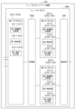
図5は、ニューラルネットワーク装置10における層毎のデータ処理のタイミングの例を示す図である。図5では、図2に示される4層構成の場合を例に、入力層21、中間層の第1層(中間層22-1)、中間層の第2層(中間層22-2)、出力層23のそれぞれのノード30がデータを処理するタイミングを示している。第1層および第2層の何れでも、ノード30としてニューロンモデル100が用いられる。
Figure 5 is a diagram showing an example of the timing of data processing for each layer in the
図5の横軸は、時刻を、ニューラルネットワーク装置10へのデータ入力開始時からの経過時間で示す。
図5の例で、横軸が示す時間は、時間幅T毎の時間区間に分割されている。
ニューラルネットワーク装置10は、全てのニューロンモデル100に同じ時間幅の時間区間が同じタイミングで設定されるように、ニューロンモデル100間で同期をとって同じ時間区間を設定する。
The horizontal axis of FIG. 5 indicates time, which is the amount of time that has elapsed since the start of data input to the
In the example of FIG. 5, the time indicated by the horizontal axis is divided into time intervals each having a time width T.
The
あるいは、スパイク信号の伝達における遅延時間を無視できない場合、ニューラルネットワーク装置10が層毎に、層内の全てのニューロンモデル100間で同期をとって同じ時間区間を設定し、相関では、スパイク信号の伝達における遅延時間分だけずらして時間区間を設定するようにしてもよい。
Alternatively, if the delay time in the transmission of spike signals cannot be ignored, the
入力層21のノード30は、時間区間毎にデータをスパイク信号の形式で第1層のノード30へ出力する。図5の例では、入力層21のノード30は、第1データ、第2データおよび第3データの3つのデータを第1層のノード30へ出力している。ただし、入力層21のノード30が出力するデータの個数は、特定の個数に限定されない。
The
第1層のノード30は、入力層21のノード30からデータの入力を受ける毎に、データの入力を受けた時間区間の次の時間区間に、そのデータの処理のための中間データをスパイク信号の形式で第2層のノード30に出力する。例えば、第1層のノード30は、時刻0からTまでの時間区間に第1データの入力を受け、時刻Tから2Tまでの時間区間に、第1データの処理のための中間データを第2層のノード30へ出力する。
Each time a
第2層のノード30は、第1層のノード30からデータの入力を受ける毎に、データの入力を受けた時間区間の次の時間区間に、そのデータの処理のための中間データをスパイク信号の形式で出力層のノード30に出力する。例えば、第2層のノード30は、時刻Tから2Tまでの時間区間に第1データの処理のための中間データの入力を受け、時刻2Tから3Tまでの時間区間に、第1層のノード30からのデータにさらに処理を加えた中間データを出力層のノード30へ出力する。
Each time the
出力層のノード30は、第2層のノード30からデータの入力を受ける毎に、そのデータにさらに処理を加えた出力データをスパイク信号の形式で出力する。
出力層のノード30からの出力データは、さらにノードに入力されるものではないため、図5の例で、出力層のノード30は、データの入力を受けた時間区間にデータを出力している。
Each time the
The output data from the
このように、ニューラルネットワーク装置10では、データ処理を行う時間区間が決まっていることで、1つのデータの処理の完了を待たずに次のデータの処理を開始することができる。
また、ニューラルネットワーク装置10では、第1層および第2層の例のように、ニューロンモデル100は、スパイク信号の入力を受けた時間区間の次の時間区間にスパイク信号を出力する。これにより、ニューロンモデル100は、時間区間内におけるスパイク信号出力のタイミングを調整することができる。スパイク信号出力のタイミングを調整することで、ニューラルネットワーク装置10では、例えば、信号伝達における下流側の層でスパイク信号の入力のタイミングが時間区間内の後ろのほう(その時間区間の終了時付近)に偏ることを回避できる。
In this way, since the time interval for data processing is determined in the
In the
図5に例示されるタイミングでデータ処理を行うために、ニューロンモデル100は、上述したように、時間区間毎のスパイク信号の入力状況に応じて、その次の時間区間にてスパイク信号を出力する。
以下では、式(1)および式(2)を参照してスパイキングニューラルネットワークについて説明したのと同様、第l層のi番目のノードのニューロンモデル100を対象モデルと称し、対象モデルの膜電位をvi
(l)(t)と表記する。また、第l-1層のj番目のスパイキングニューロンモデルから対象モデルへのスパイク信号の伝達経路に設定されている重みをwij
(l)と表記する。
In order to perform data processing at the timing illustrated in FIG. 5, the
In the following, as in the explanation of the spiking neural network with reference to formulas (1) and (2), the
指標値計算部110は、時間区間毎に、その時間区間におけるスパイク信号のニューロンモデル100への入力状況に基づいて膜電位を変化させる。指標値計算部110は、指標値計算手段の例に該当する。
指標値計算部110は、膜電位vi
(l)(t)が閾値Vthに達するまで、または、時間区間が終了するまでの何れか早い方の事象が発生するまで、微分方程式が式(1)のように表される膜電位vi
(l)(t)を計算する。膜電位vi
(l)(t)は、式(3)のように表される。
The index
The index

指標値計算部110が、式(3)に基づいて膜電位を計算するようにしてもよい。
一方、膜電位vi
(l)(t)が閾値Vthに達したタイミング、または、時間区間が終了したタイミングで、指標値計算部110は、膜電位vi
(l)(t)の値を0にリセットする。指標値計算部110は、次の時間区間の開始時まで膜電位vi
(l)(t)の値を0に維持する。これにより、指標値計算部110は、各時間区間における膜電位vi
(l)(t)の計算を、膜電位vi
(l)(t)の値が0の状態から開始する。
The index
On the other hand, when the membrane potential v i (l) (t) reaches the threshold value V th or when the time interval ends, the index
膜電位vi (l)(t)が閾値Vthに達する時刻をti (l,vth)と表記して式(3)の時刻tに代入すると、式(4)を得られる。 When the time when the membrane potential v i (l) (t) reaches the threshold value V th is expressed as t i (l, vth) and substituted for time t in equation (3), equation (4) is obtained.

Γi
(l)は、tj
*(l-1)<ti
(l,vth)となるインデックスjの集合を表す。
ニューラルネットワーク装置10では、発火時刻が出力時間区間内に制限されるため、発火時刻ti
*(l)が、膜電位vi
(l)(t)が閾値Vthに達する時刻よりも後の時刻になる場合がある。このように、膜電位vi
(l)(t)が閾値Vthに達する時刻と発火時刻ti
*(l)とが異なる場合があることから、膜電位vi
(l)(t)が閾値Vthに達する時刻をti
(l,vth)と表記している。膜電位が閾値に達する時刻を、閾値到達時刻とも称する。
式(4)より、閾値到達時刻ti
(l,vth)は、式(5)のように表される。
Γ i (l) denotes the set of indexes j for which t j *(l-1) < t i (l, vth) .
In the
From equation (4), the threshold reaching time t i (l, vth) is expressed as in equation (5).

検出部120は、膜電位に関する所定の事象の発生タイミングを検出する。検出部120は、検出手段の例に該当する。
ここでいう膜電位に関する所定の事象は、膜電位が所定の閾値に達したこと、または、データ処理時間の終了時までに膜電位が所定の閾値に到達しないことであってもよい。ここでいう膜電位に関する所定の事象の発生タイミングは、膜電位が所定の閾値に達したタイミング、または、データ処理時間の終了時であってもよい。
The
The predetermined event related to the membrane potential may be that the membrane potential reaches a predetermined threshold value or that the membrane potential does not reach a predetermined threshold value by the end of the data processing time. The timing of the occurrence of the predetermined event related to the membrane potential may be that the membrane potential reaches a predetermined threshold value or the end of the data processing time.
検出部120が検出する、膜電位に関する所定の事象の発生タイミングを、事象発生タイミングとも称する。時間区間内に膜電位vi
(l)(t)が閾値Vthに達した場合、検出部120は、膜電位vi
(l)(t)が閾値Vthに達したタイミングを、事象発生タイミングとして検出する。一方、時間区間内に膜電位vi
(l)(t)が閾値Vthに達しない場合、検出部120は、その時間区間の終了時を、事象発生タイミングとして検出する。
The occurrence timing of a specific event related to the membrane potential detected by the
遅延部130は、ニューロンモデル100がスパイク信号を出力するタイミングを決定する。特に、遅延部130は、時間区間毎に、その前の時間区間における事象発生タイミングに基づいて、ニューロンモデル100がスパイク信号を出力するタイミングを決定する。
The
具体的には、遅延部130は、事象発生タイミングから所定の条件の分の時間だけ遅延したタイミングを検出する。遅延部130が検出する、事象発生タイミングから所定の条件の分の時間だけ遅延したタイミングを、遅延後タイミングとも称する。
Specifically, the
遅延後タイミングが事象発生タイミングと同じ時間区間に含まれる場合、遅延部130は、その時間区間の次の時間区間の開始時を、ニューロンモデル100がスパイク信号を出力するタイミングに決定する。
遅延後タイミングが含まれる時間区間が、事象発生タイミングが含まれる時間区間の次の時間区間である場合、遅延部130は、遅延後タイミングを、ニューロンモデル100がスパイク信号を出力するタイミングに決定する。
事象発生タイミングが含まれる次の時間区間中までに遅延後タイミングを検出しない場合、遅延部130は、事象発生タイミングが含まれる次の時間区間の終了時を、ニューロンモデル100がスパイク信号を出力するタイミングに決定する。
If the delayed timing is included in the same time interval as the event occurrence timing, the
When the time interval including the delayed timing is the time interval next to the time interval including the event occurrence timing, the
If the delayed timing is not detected by the time of the next time interval that includes the event occurrence timing, the
信号出力部140は、遅延部130が決定するタイミングで、スパイク信号を出力する。これにより信号出力部140は、時間区間のうち第1時間区間内のタイミング、かつ、第1時間区間よりも過去の時間区間である第2時間区間における所定の事象の発生タイミングに応じたタイミングで、スパイク信号を出力する。ここでは、第1時間区間は、ニューロンモデル100スパイク信号を出力する時間区間である。第2時間区間は、ニューロンモデル100が、第1時間区間でのスパイク信号出力タイミングを決定する元となるスパイク信号の入力を受ける時間区間である。
信号出力部140は、信号出力手段の例に該当する。
The
The
図6は、ニューラルネットワーク装置のより具体的な構成の第1例を示す図である。
図6に示す構成で、ニューラルネットワーク装置10aは、ニューロンモデル100aを備える。ニューロンモデル100aは、第1サブモデル210-1と、切替部220aと、第2サブモデル210-2と、第3サブモデル210-3と、統合部230とを備える。第1サブモデル210-1は、第1指標値計算部211-1と、第1検出部212-1と、第1信号出力部213-1とを備える。第2サブモデル210-2は、第2指標値計算部211-2と、第2検出部212-2と、第2信号出力部213-2とを備える。第3サブモデル210-3は、第3指標値計算部211-3と、第3検出部212-3と、第3信号出力部213-3とを備える。
FIG. 6 is a diagram showing a first example of a more specific configuration of a neural network device.
In the configuration shown in Fig. 6, the
第1サブモデル210-1と、第2サブモデル210-2と、第3サブモデル210-3とを総称してサブモデル210とも表記する。第2サブモデル210-2と、第3サブモデル210-3とを総称して遅延用サブモデル210fとも表記する。
第1指標値計算部211-1と、第2指標値計算部211-2と、第3指標値計算部211-3とを総称して指標値計算部211とも表記する。第2指標値計算部211-2と、第3指標値計算部211-3とを総称して遅延用指標値計算部211fとも表記する。
The first sub-model 210-1, the second sub-model 210-2, and the third sub-model 210-3 are also collectively referred to as sub-models 210. The second sub-model 210-2 and the third sub-model 210-3 are also collectively referred to as a delay sub-model 210f.
The first index value calculation unit 211-1, the second index value calculation unit 211-2, and the third index value calculation unit 211-3 are also collectively referred to as index
第1検出部212-1と、第2検出部212-2と、第3検出部212-3とを総称して検出部212とも表記する。第2検出部212-2と、第3検出部212-3とを総称して遅延用検出部212fとも表記する。
第1信号出力部213-1と、第2信号出力部213-2と、第3信号出力部213-3とを総称して信号出力部213とも表記する。第2信号出力部213-2と、第3信号出力部213-3とを総称して遅延用信号出力部213fとも表記する。
The first detection unit 212-1, the second detection unit 212-2, and the third detection unit 212-3 are also collectively referred to as
The first signal output section 213-1, the second signal output section 213-2, and the third signal output section 213-3 are also collectively referred to as
サブモデル210は、スパイキングニューロンモデルとして構成されている。具体的には、指標値計算部211は、サブモデル210へのスパイク信号の入力状況に基づいて、膜電位を時間変化させる。第1サブモデル210-1は、第1スパイキングニューロンモデルの例に該当する。2つの遅延用サブモデル210fは、2つの第2スパイキングニューロンモデルの例に該当する。
The
検出部212は、膜電位に関する所定の事象の発生タイミングを検出する。
具体的には、第1検出部212-1は、膜電位と所定の閾値とを比較する。時間区間内で膜電位が閾値に達する場合、第1検出部212-1は、膜電位が閾値に達するタイミングを検出する。膜電位が閾値に達しないまま時間区間が終了する場合、第1検出部212-1は、その時間区間の終了タイミングを検出する。
The
Specifically, the first detection unit 212-1 compares the membrane potential with a predetermined threshold. If the membrane potential reaches the threshold within a time interval, the first detection unit 212-1 detects the timing at which the membrane potential reaches the threshold. If the time interval ends before the membrane potential reaches the threshold, the first detection unit 212-1 detects the end timing of the time interval.
遅延用サブモデル210fでは、時間区間が、遅延用サブモデル210fがスパイク信号の入力を受ける時間区間と、遅延用サブモデル210fがスパイク信号を出力する時間区間とに分けられる。遅延用サブモデル210fがスパイク信号の入力を受ける時間区間を、入力時間区間とも称する。遅延用サブモデル210fがスパイク信号を出力する時間区間を、出力時間区間とも称する。
入力時間区間は、遅延用サブモデル210fが第1サブモデル210-1からのスパイク信号の入力を受ける時間区間である。出力時間区間は、入力時間区間の次の時間区間である。
In the delay submodel 210f, the time interval is divided into a time interval in which the delay submodel 210f receives a spike signal as an input and a time interval in which the delay submodel 210f outputs a spike signal. The time interval in which the delay submodel 210f receives a spike signal as an input time interval is also referred to as an input time interval. The time interval in which the delay submodel 210f outputs a spike signal is also referred to as an output time interval.
The input time interval is a time interval during which the delay sub-model 210f receives an input of a spike signal from the first sub-model 210-1. The output time interval is a time interval following the input time interval.
遅延用検出部212fは、膜電位と所定の閾値とを比較する。出力時間区間内で膜電位が閾値に達する場合、検出部212は、膜電位が閾値に達するタイミングを検出する。膜電位が閾値に達しないまま出力時間区間が終了する場合、検出部212は、その時間区間の終了タイミングを検出する。
また、入力時間区間内に膜電位が閾値に達する場合、遅延用検出部212fは、その次の時間区間の開始タイミングを検出する。この場合、「その次の時間区間」は、出力時間区間に該当する。
The delay detector 212f compares the membrane potential with a predetermined threshold. If the membrane potential reaches the threshold within the output time interval, the
Moreover, when the membrane potential reaches the threshold value within the input time interval, the delay detector 212f detects the start timing of the next time interval. In this case, the "next time interval" corresponds to the output time interval.
信号出力部213は、検出部120が検出する所定の事象の発生タイミングで、スパイク信号を出力する。
例えば、第1信号出力部213-1は、第1検出部212-1が検出する、膜電位が閾値に達するタイミング、または、膜電位が閾値に達しないまま時間区間が終了する場合の、その時間区間の終了タイミングにて、スパイク信号を出力する。
The
For example, the first signal output unit 213-1 outputs a spike signal at the timing when the membrane potential detected by the first detection unit 212-1 reaches a threshold value, or at the end of a time period when the time period ends without the membrane potential reaching the threshold value.
また、遅延用信号出力部213fは、遅延用検出部212fが検出する、出力時間区間内で膜電位が閾値に達するタイミング、膜電位が閾値に達しないまま出力時間区間が終了する場合の、その時間区間の終了タイミング、または、入力時間区間内に膜電位が閾値に達する場合の、その次の時間区間の開始タイミングにて、スパイク信号を出力する。 The delay signal output unit 213f also outputs a spike signal at the timing when the membrane potential reaches the threshold within the output time interval detected by the delay detection unit 212f, at the end of the output time interval if the output time interval ends before the membrane potential reaches the threshold, or at the start of the next time interval if the membrane potential reaches the threshold within the input time interval.
切替部220aは、第1サブモデル210-1からのスパイク信号の伝達先を、2つの遅延用サブモデル210fの何れかに切り替える。
統合部230は、2つの遅延用サブモデル210fそれぞれから出力されるスパイク信号を統合する。
The
The integrating
ここでのスパイク信号を統合することは、2つの遅延用サブモデル210fそれぞれから出力されるスパイク信号のorをとることであってもよい。具体的には、時間区間毎に、2つの遅延用サブモデル210fのうち何れか一方の遅延用サブモデル210fが、スパイク信号を出力する。統合部230は、時間区間毎に、何れか一方の遅延用サブモデル210fが出力するスパイク信号を、ニューロンモデル100aの出力として出力する。
The integration of the spike signals here may be the OR of the spike signals output from each of the two delay submodels 210f. Specifically, for each time interval, one of the two delay submodels 210f outputs a spike signal. The
ニューラルネットワーク装置10aは、ニューラルネットワーク装置10の例に該当する。
第1指標値計算部211-1は、指標値計算部110の例に該当する。第1指標値計算部211-1は、指標値計算手段の例にも該当する。
第1検出部212-1は、検出部120の例に該当する。第1検出部212-1は、検出手段の例にも該当する。
The
The first index value calculation unit 211-1 corresponds to an example of the index
The first detection unit 212-1 corresponds to an example of the
遅延用指標値計算部211fと遅延用検出部212fとの組み合わせは、遅延部130の例に該当する。遅延用指標値計算部211fと遅延用検出部212fとの組み合わせは、遅延手段の例にも該当する。
遅延用信号出力部213fは、信号出力部140の例に該当する。遅延用信号出力部213fは、信号出力手段の例にも該当する。
The combination of the delay index value calculator 211f and the delay detector 212f corresponds to an example of the
The delay signal output section 213f corresponds to an example of the
図7は、切替部220aおよび統合部230の構成の例を示す図である。
図7の例で、切替部220aは、スイッチ221を含んで構成される。切替部220aは、入力されるクロック信号に基づいて、時間区間毎にスイッチ221を切り替える。これにより、切替部220aは、第1サブモデル210-1からのスパイク信号の出力先の遅延用サブモデル210fを時間区間毎に切り替える。
切替部220aは、切替手段の例に該当する。
FIG. 7 is a diagram showing an example of the configuration of the
7, the
The
統合部230は、スイッチ231とインバータ232とを含んで構成される。統合部230は、入力されるクロック信号をインバータ232で反転させ、反転後のクロック信号に基づいて、時間区間毎にスイッチ231を切り替える。これにより、統合部230は、スパイク信号を出力する遅延用サブモデル210fを、時間区間毎に、第1サブモデル210-1からのスパイク信号の入力を受けない方の遅延用サブモデル210fに切り替える。
ただし、切替部220aおよび統合部230の構成は、図7に例示される構成に限定されない。
The
However, the configurations of the
図8は、ニューラルネットワーク装置10aにおけるニューロンモデル100a間のスパイク信号の受け渡しのタイミングの例を示す図である。図8は、1つのニューロンモデル100aにおける第1サブモデル210-1および2つの遅延用サブモデル210fの間のスパイク信号の受け渡し、および、2つの遅延用サブモデル210fと、それらの遅延用サブモデル210fからのスパイク信号の入力を受けるニューロンモデル100aの第1サブモデル210-1との間のスパイク信号の受け渡しの例を示している。
Figure 8 shows an example of the timing of spike signal transfer between
図8のグラフの横軸は、時刻を、図8中でスパイク信号を出力する側のニューロンモデル100aに最初の入力データが入力されてからの経過時間で示す。縦軸は、第1サブモデル210-1、第2サブモデル210-2、第3サブモデル210-3、遅延用サブモデル210fからのスパイク信号の入力を受ける第1サブモデル210-1それぞれの膜電位を示す。
図5の例でニューラルネットワーク装置10について説明したのと同様、図8の横軸に示される時間は、時間幅T毎の時間区間に分割されている。
The horizontal axis of the graph in Fig. 8 indicates time, which is the elapsed time from when the first input data is input to the
As in the case of the
第1サブモデル210-1は、時間区間の開始時には膜電位が0にリセットされた状態になっている。第1指標値計算部211-1が第1サブモデル210-1の発火時に膜電位を0に設定し、次の時間区間の開始時まで膜電位を0とする設定を維持するようにしてもよい。
時間区間の開始時から第1サブモデル210-1の発火時まで、第1指標値計算部211-1は、時間区間内に受けるスパイク信号の取得状況に応じて膜電位を時間変化させる。
第1サブモデル210-1は、膜電位が閾値に到達したタイミングで発火する。時間区間内に膜電位が閾値に達しない場合、第1サブモデル210-1は、時間区間の終了時に発火する。
膜電位が閾値に達していない状態での発火を強制発火とも称する。
At the start of the time interval, the membrane potential of the first submodel 210-1 is reset to 0. The first index value calculation unit 211-1 may set the membrane potential to 0 when the first submodel 210-1 fires, and may maintain the membrane potential at 0 until the start of the next time interval.
From the start of the time interval until the firing of the first sub-model 210-1, the first index value calculation section 211-1 changes the membrane potential over time according to the acquisition status of the spike signal received within the time interval.
The first submodel 210-1 fires when the membrane potential reaches a threshold value. If the membrane potential does not reach the threshold value within the time interval, the first submodel 210-1 fires at the end of the time interval.
Firing when the membrane potential does not reach the threshold is also called forced firing.
第1サブモデル210-1からのスパイク信号は、2つの遅延用サブモデル210fの何れかに入力される。例えば、奇数番目のデータの処理におけるスパイク信号が、第2サブモデル210-2に入力され、偶数番目のデータ処理におけるスパイク信号が、第3サブモデル210-3に入力されるようにしてもよい。上記のように、切替部220aが、第1サブモデル210-1からのスパイク信号を、2つの遅延用サブモデル210fの何れかに振り分ける。
The spike signal from the first submodel 210-1 is input to one of the two delay submodels 210f. For example, the spike signal in the processing of odd-numbered data may be input to the second submodel 210-2, and the spike signal in the processing of even-numbered data may be input to the third submodel 210-3. As described above, the
遅延用サブモデル210fは、第1サブモデル210-1からのスパイク信号の入力を受けた時間区間の次の時間区間にてスパイク信号を出力する。
上記のように、遅延用サブモデル210fがスパイク信号の入力を受ける時間区間を入力時間区間とも称する。遅延用サブモデル210fがスパイク信号を出力する時間区間を出力時間区間とも称する。第2サブモデル210-2と第3サブモデル210-3とで入力時間区間と出力時間区間とが逆になる。すなわち、第2サブモデル210-2における時間区間が入力時間区間であるときは、第3サブモデル210-3における時間区間は出力時間区間となっている。第2サブモデル210-2における時間区間が出力時間区間であるときは、第3サブモデル210-3における時間区間は入力時間区間となっている。
The delay sub-model 210f outputs a spike signal in the time interval following the time interval in which the spike signal was received from the first sub-model 210-1.
As described above, the time interval during which the delay submodel 210f receives the input of a spike signal is also referred to as an input time interval. The time interval during which the delay submodel 210f outputs a spike signal is also referred to as an output time interval. The input time interval and the output time interval are reversed between the second submodel 210-2 and the third submodel 210-3. That is, when the time interval in the second submodel 210-2 is an input time interval, the time interval in the third submodel 210-3 is an output time interval. When the time interval in the second submodel 210-2 is an output time interval, the time interval in the third submodel 210-3 is an input time interval.
入力時間区間の開始時には、遅延用サブモデル210fの膜電位は0にリセットされた状態になっている。遅延用サブモデル210fの指標値計算部211が遅延用サブモデル210fの発火時に膜電位を0に設定し、次の時間区間の開始時まで膜電位を0とする設定を維持するようにしてもよい。遅延用サブモデル210fの発火は出力時間区間にて行われ、ここでの「次の時間区間」は入力時間区間になる。
At the start of the input time interval, the membrane potential of the delay submodel 210f is reset to 0. The index
遅延用サブモデル210fは、遅延用サブモデル210f自らが含まれるニューロンモデル100aと同じニューロンモデル100aに含まれる1つの第1サブモデル210-1のみからのスパイク信号の入力を受ける。
第1サブモデル210-1からのスパイク信号の入力を受けると、遅延用指標値計算部211fは、スパイク信号の伝達経路に設定されている重みに応じた変化率(変化速度)で膜電位を増加させる。
The delay sub-model 210f receives a spike signal input only from the first sub-model 210-1 included in the
When a spike signal is input from the first sub-model 210-1, the delay index value calculation unit 211f increases the membrane potential at a rate of change (speed of change) according to the weighting set in the transmission path of the spike signal.
入力時間区間内で膜電位が閾値に達した場合、遅延用信号出力部213fは、出力時間区間の開始時にスパイク信号を出力する。例えば、膜電位が閾値に達してから出力時間区間の開始時まで、遅延用指標値計算部211fが、膜電位を閾値と同じ値で維持する。そして、出力時間区間の開始時に、遅延用検出部212fが、膜電位が閾値に達していることを検出し、遅延用信号出力部213fが、遅延用検出部212fの検出結果に基づいてスパイク信号を出力する。発火後、遅延用指標値計算部211fは、膜電位を0に設定する。 When the membrane potential reaches the threshold within the input time interval, the delay signal output unit 213f outputs a spike signal at the start of the output time interval. For example, from when the membrane potential reaches the threshold until the start of the output time interval, the delay index value calculation unit 211f maintains the membrane potential at the same value as the threshold. Then, at the start of the output time interval, the delay detection unit 212f detects that the membrane potential has reached the threshold, and the delay signal output unit 213f outputs a spike signal based on the detection result of the delay detection unit 212f. After firing, the delay index value calculation unit 211f sets the membrane potential to 0.
出力時間区間内で膜電位が閾値に達した場合、遅延用検出部212fが、膜電位が閾値に達していることを検出し、遅延用信号出力部213fが、遅延用検出部212fの検出結果に基づいてスパイク信号を出力する。発火後、遅延用指標値計算部211fは、膜電位を0に設定する。 When the membrane potential reaches the threshold within the output time interval, the delay detection unit 212f detects that the membrane potential has reached the threshold, and the delay signal output unit 213f outputs a spike signal based on the detection result of the delay detection unit 212f. After firing, the delay index value calculation unit 211f sets the membrane potential to 0.
出力時間区間終了までに膜電位が閾値に達しなかった場合、遅延用信号出力部213fは、強制発火にてスパイク信号を出力する。例えば、出力時間区間の終了時までに膜電位が一度も閾値に達していない場合、遅延用検出部212fが、膜電位が閾値に達したとするダミーの判定結果を遅延用信号出力部213fに出力するようにしてもよい。そして、遅延用信号出力部213fが、遅延用検出部212fのダミーの判定結果に基づいて、出力時間区間の終了時にスパイク信号を出力するようにしてもよい。発火後、遅延用指標値計算部211fは、膜電位を0に設定する。 If the membrane potential does not reach the threshold by the end of the output time interval, the delay signal output unit 213f outputs a spike signal by forced firing. For example, if the membrane potential has never reached the threshold by the end of the output time interval, the delay detection unit 212f may output a dummy judgment result that the membrane potential has reached the threshold to the delay signal output unit 213f. Then, the delay signal output unit 213f may output a spike signal at the end of the output time interval based on the dummy judgment result of the delay detection unit 212f. After firing, the delay index value calculation unit 211f sets the membrane potential to 0.
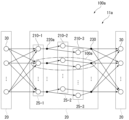
図9は、ニューラルネットワーク装置10aにおける副層(Sublayer)の構成の例を示す図である。
ニューラルネットワーク装置10aが備えるスパイキングニューラルネットワークを、ニューラルネットワーク11aとも表記する。ニューラルネットワーク11aは、ニューラルネットワーク11の例に該当する。
FIG. 9 is a diagram showing an example of a sublayer configuration in the
The spiking neural network included in the
図9の例で、ノード30としてニューロンモデル100aを含む層20が、副層を含んで構成されている。第1サブモデル210-1を含む副層を演算層と称し、符号25-1を付加する。第2サブモデル210-2を含む副層を第1遅延層と称し、符号25-2を付加する。第3サブモデル210-3を含む副層を第2遅延層と称し、符号25-3を付加する。
副層が第i層(iは正の整数)に含まれる場合、演算層を第i演算層とも称し、第1遅延層を第i-1遅延層とも称し、第2遅延層を第i-2遅延層とも称する。
In the example of Fig. 9, the
When a sublayer is included in the i-th layer (i is a positive integer), the computation layer is also referred to as the i-th computation layer, the first delay layer is also referred to as the i-1-th delay layer, and the second delay layer is also referred to as the i-2-th delay layer.
第1サブモデル210-1がスパイク信号を出力すると、切替部220aが、第1サブモデル210-1からのスパイク信号を、2つの遅延用サブモデル210fの何れかに伝送する。第1サブモデル210-1からのスパイク信号の入力を受けた遅延用サブモデル210fが、その次の時間区間に出力するスパイク信号は、統合部230を経由して次の層20のノード30に入力される。
When the first submodel 210-1 outputs a spike signal, the
図10は、ニューラルネットワーク装置10aにおけるデータ処理のタイミングの例を示す図である。図10の横軸は、時刻を、ニューラルネットワーク11aへのデータ入力開始時からの経過時間で示す。図10の例では、横軸に示される時間が、時間T毎の時間区間に区切られている。
Figure 10 is a diagram showing an example of the timing of data processing in the
また、図10は、ニューラルネットワーク11aが、入力層、第1層、第2層および出力層の4層で構成され、、第1データ、第2データ、および、第3データの3つのデータを処理する場合の例を示している。層毎または副層毎に、その層または副層で各データを処理する時間区間を示している。
Figure 10 also shows an example in which the
図10の例で、入力層のノード30は、1つの時間区間で1つのデータを第1演算層のノード30に出力する。
演算層では、第1サブモデル210-1が、データの入力を受けた時間区間内でそのデータに対する処理を行い、遅延層の遅延用サブモデル210fへスパイク信号にてデータを出力する。第1サブモデル210-1におけるデータ処理は、発火タイミングを決定する処理であってもよい。
In the example of FIG. 10, the
In the computation layer, the first submodel 210-1 processes the input data within the time interval in which the data is received, and outputs the data as a spike signal to the delay submodel 210f in the delay layer. The data processing in the first submodel 210-1 may be a process for determining the firing timing.
遅延層では、遅延用サブモデル210fが、入力時間区間にデータの入力を受ける。遅延用サブモデル210fは、入力時間区間の次の時間区間である出力時間区間のうち、入力時間区間でデータの入力を受けたタイミングに応じたタイミングでスパイク信号を出力することで、次の層のノードへデータを出力する。遅延用サブモデル210fは、入力時間区間にて入力を受けたスパイク信号を、出力時間区間まで遅延させて出力するものといえる。
出力層のノード30は、データの入力を受けた時間区間内でそのデータに対する処理を行い、処理結果のデータをスパイク信号にて出力する。
In the delay layer, the delay submodel 210f receives data input in an input time interval. The delay submodel 210f outputs data to a node in the next layer by outputting a spike signal at a timing corresponding to the timing of receiving the data input in the input time interval, during an output time interval that is the next time interval after the input time interval. It can be said that the delay submodel 210f outputs a spike signal received in the input time interval by delaying it to the output time interval.
The
このように、各層について1つのデータの処理時間が定められていることで、ニューラルネットワーク装置10aでは、1つのデータの処理の終了を待たずに、パイプライン処理方式で次のデータ処理を開始することができる。
また、遅延用サブモデル210fが、入力時間区間にてスパイク信号の入力を受け、次の時間区間である出力時間区間まで遅らせてスパイク信号を出力することで、時間区間内におけるスパイク信号の出力タイミングを調整することができる。例えば、データの流れの下流側の層で、スパイク信号の入力が時間区間の最後付近に集中することを回避し得る。
また、1つの第1サブモデル210-1に対して2つの遅延用サブモデル210fが設けられていることで、遅延用サブモデル210fの各々が1つのデータの処理を2つの時間区間にわたって行っても(おこなっても)、第1サブモデル210-1は、時間区間毎にデータを遅延用サブモデル210fへ出力することができる。
In this way, by determining the processing time for one piece of data for each layer, the
In addition, the delay submodel 210f receives a spike signal in an input time interval and outputs the spike signal after delaying it until the output time interval, which is the next time interval, so that the output timing of the spike signal within the time interval can be adjusted. For example, it is possible to prevent the input of spike signals from concentrating near the end of the time interval in a downstream layer of the data flow.
In addition, since two delay sub-models 210f are provided for one first sub-model 210-1, even if each of the delay sub-models 210f processes one piece of data over two time intervals, the first sub-model 210-1 can output data to the delay sub-model 210f for each time interval.
第l層のi番目のニューロンモデル100の第1サブモデル210-1の発火前の膜電位vi_1
(l)(t)は、式(6)のように表すことができる。
The membrane potential v i — 1 (l) (t) before firing of the first sub-model 210-1 of the i-
この第1サブモデル210-1における閾値到達時刻をti_1 (l,vth)とすると、式(7)を得られる。 If the threshold reaching time in this first sub-model 210-1 is t i — 1 (l, vth) , then equation (7) is obtained.

Γi_1
(l)は、tj
*(l-1)<ti_1
(l,vth)となるインデックスjの集合を表す。
閾値到達時刻ti_1
(l,vth)は、式(8)のように表される。
Γ i — 1 (l) represents the set of indexes j for which t j *(l−1) <t i — 1 (l, vth) .
The threshold reaching time t i — 1 (l, vth) is expressed as in equation (8).

この第1サブモデル210-1がd番目のデータを処理する際の発火時刻ti_1 *(l)は、式(9)のように表すことができる。 The ignition time t i — 1 *(l) when the first sub-model 210-1 processes the d-th data can be expressed as in equation (9).

関数clipは、式(10)のように示される。 The function clip is shown in equation (10).

式(10)に示される関数clipをクリップ関数とも称する。
図11は、クリップ関数の第1例を示す図である。図11は、第l層のi番目のニューロンモデル100の第1サブモデル210-1が、第dデータを処理する際のクリップ関数の例を示す。
図11のグラフの横軸は、膜電位が閾値に達する時刻を、ニューラルネットワーク11aへのデータ入力開始時からの経過時間で示す。縦軸は、第1サブモデル210-1の発火時刻を、ニューラルネットワーク11aへのデータ入力開始時からの経過時間で示す。
The function clip shown in equation (10) is also called a clip function.
Fig. 11 is a diagram showing a first example of a clip function when the first sub-model 210-1 of the i-
11, the horizontal axis represents the time when the membrane potential reaches the threshold value as the elapsed time from the start of data input to the
時刻(l+d-2)Tから(l+d-1)Tまでの時間は、第l層のi番目のニューロンモデル100の第1サブモデル210-1が、第dデータを処理する時間区間に該当する。この時間区間内に膜電位が閾値に達した場合、第1検出部212-1が、膜電位が閾値に達したことを検出すると、第1信号出力部213-1がスパイク信号を出力する。
一方、この時間区間内に膜電位が閾値に達しない場合は、時刻(l+d-1)T以降に膜電位が閾値に達するものとして捉えることができる。この場合、第1信号出力部213-1は、この時間区間の終了時である時刻(l+d-1)Tにスパイク信号を出力する。
The time from (l+d-2)T to (l+d-1)T corresponds to the time interval during which the first sub-model 210-1 of the i-
On the other hand, if the membrane potential does not reach the threshold within this time interval, it can be regarded as reaching the threshold after time (l+d-1) T. In this case, the first signal output section 213-1 outputs a spike signal at time (l+d-1) T, which is the end of this time interval.
第l層のi番目のニューロンモデル100の遅延用サブモデル210fの発火前の膜電位vi_f
(l)(t)は、式(11)のように表すことができる。
The membrane potential v i — f (l) (t) before firing of the delay sub-model 210 f of the i-

wfは、第1サブモデル210_1から遅延用サブモデル210fへのスパイク信号の伝達経路に設定されている重みを示す。wfが学習の対象となっていてもよい。
この遅延用サブモデル210fにおける閾値到達時刻をti_f
(l,vth)とすると、式(12)を得られる。
wf indicates a weight set in the transmission path of the spike signal from the first sub-model 210_1 to the delay sub-model 210f. wf may be the target of learning.
When the threshold reaching time in this delay sub-model 210f is denoted by t i — f (l, vth) , equation (12) is obtained.
![]()
![]()
閾値到達時刻ti_f (l,vth)は、式(13)のように表される。 The threshold reaching time t i — f (l, vth) is expressed as in equation (13).

この遅延用サブモデル210fがd番目のデータを処理する際の発火時刻ti_f *(l)は、式(14)のように表すことができる。 The ignition time t i — f *(l) when the delay submodel 210 f processes the d-th data can be expressed as in equation (14).
![]()
![]()
図12は、クリップ関数の第2例を示す図である。図12は、第l層のi番目のニューロンモデル100の遅延用サブモデル210fが、第dデータを処理する際のクリップ関数の例を示す。
図12のグラフの横軸は、膜電位が閾値に達する時刻を、ニューラルネットワーク11aへのデータ入力開始時からの経過時間で示す。縦軸は、遅延用サブモデル210fの発火時刻を、ニューラルネットワーク11aへのデータ入力開始時からの経過時間で示す。
Fig. 12 is a diagram showing a second example of the clip function. Fig. 12 shows an example of the clip function when the delay sub-model 210f of the i-
12, the horizontal axis indicates the time when the membrane potential reaches the threshold value as the elapsed time from the start of data input to the
時刻(l+d-2)Tから(l+d-1)Tまでの時間は、第l層のi番目のニューロンモデル100の遅延用サブモデル210fが、第dデータを処理する場合の入力時間区間に該当する。時刻(l+d-1)Tから(l+d)Tまでの時間は、第l層のi番目のニューロンモデル100の遅延用サブモデル210fが、第dデータを処理する場合の出力時間区間に該当する。
入力時間区間内に膜電位が閾値に達した場合、遅延用信号出力部213fは、この入力時間区間の次の時間区間である出力時間区間の開始時に、スパイク信号を出力する。
The time from (l+d-2)T to (l+d-1)T corresponds to the input time interval when the delay submodel 210f of the i-
When the membrane potential reaches the threshold within the input time interval, the delay signal output section 213f outputs a spike signal at the start of the output time interval, which is the next time interval following this input time interval.
出力時間区間内に膜電位が閾値に達した場合、遅延用検出部212fが、膜電位が閾値に達したことを検出すると、遅延用信号出力部213fがスパイク信号を出力する。
出力時間区間の終了時までに膜電位が閾値に達しない場合は、時刻(l+d)T以降に膜電位が閾値に達するものとして捉えることができる。この場合、遅延用信号出力部213fは、出力時間区間の終了時である時刻(l+d)Tにスパイク信号を出力する。
When the membrane potential reaches the threshold within the output time section, the delay detection section 212f detects that the membrane potential has reached the threshold, and the delay signal output section 213f outputs a spike signal.
If the membrane potential does not reach the threshold by the end of the output time interval, it can be considered that the membrane potential will reach the threshold after time (l+d) T. In this case, the delay signal output unit 213f outputs a spike signal at time (l+d) T, which is the end of the output time interval.
図13は、第l層のi番目のニューロンモデル100aが、第dデータを処理する際のタイミングを示す関数の第1例を示す図である。
図13のグラフの横軸は、第1サブモデル210-1の膜電位が閾値に達する時刻を、ニューラルネットワーク11aへのデータ入力開始時からの経過時間で示す。縦軸は、遅延用サブモデル210fの発火時刻を、ニューラルネットワーク11aへのデータ入力開始時からの経過時間で示す。
第1サブモデル210-1の膜電位が閾値に達する時刻は、第1サブモデル210-1の発火時刻と同じ時刻として扱うことができる。また、第1サブモデル210-1の膜電位が閾値に達する時刻は、遅延用サブモデル210fがスパイク信号の入力を受ける時刻と同じ時刻として扱うことができる。
FIG. 13 is a diagram showing a first example of a function indicating the timing when the i-
13, the horizontal axis indicates the time when the membrane potential of the first sub-model 210-1 reaches the threshold value as the elapsed time from the start of data input to the
The time when the membrane potential of the first submodel 210-1 reaches the threshold value can be treated as the same time as the firing time of the first submodel 210-1. Also, the time when the membrane potential of the first submodel 210-1 reaches the threshold value can be treated as the same time as the time when the delay submodel 210f receives the input of a spike signal.
図13は、遅延用サブモデル210fがスパイク信号の入力を受けてからスパイク信号を出力するまでの時間がTである場合の例を示している。遅延用サブモデル210fがスパイク信号の入力を受けてからスパイク信号を出力するまでの時間を、遅延用サブモデル210fによる遅延時間とも称する。 Figure 13 shows an example in which the time from when the delay submodel 210f receives the input of a spike signal until when it outputs a spike signal is T. The time from when the delay submodel 210f receives the input of a spike signal until when it outputs a spike signal is also referred to as the delay time by the delay submodel 210f.
遅延用サブモデル210fによる遅延時間がTである場合、遅延用サブモデル210fは、入力時間区間内でのスパイク信号の入力を受けたタイミングと同様の、出力時間区間内におけるタイミングで、スパイク信号を出力する。ここでいう、2つの時間区間内における同じタイミングとは、それぞれの時間区間の開始時からの経過時間が同じであることであってもよい。 When the delay time by the delay submodel 210f is T, the delay submodel 210f outputs a spike signal at a timing in the output time interval that is the same as the timing at which the spike signal was input in the input time interval. Here, the same timing in the two time intervals may mean that the elapsed time from the start of each time interval is the same.
図13では、時刻(l+d-2)Tから第1サブモデル210-1における閾値到達時刻までの経過時間と、時刻(l+d-1)Tから遅延用サブモデル210fの発火時刻までの経過時間とが等しくなっている。
ここで、時刻(1+d-2)Tは、入力時間区間の開始時である。時刻(1+d-1)Tは、出力時間区間の開始時である。また、第1サブモデル210-1の膜電位が閾値に達してから、遅延用サブモデル210fがスパイク信号の入力を受けるまでの遅延時間は無視できるものとする。
したがって、図13は、遅延用サブモデル210fが、入力時間区間内でのスパイク信号の入力を受けたタイミングと同様の、出力時間区間内におけるタイミングで、スパイク信号を出力する場合を示している。
In FIG. 13, the time that has elapsed from time (l+d-2)T to the threshold reaching time in the first submodel 210-1 is equal to the time that has elapsed from time (l+d-1)T to the ignition time of the delay submodel 210f.
Here, the time (1+d-2)T is the start of the input time interval, and the time (1+d-1)T is the start of the output time interval. Also, it is assumed that the delay time from when the membrane potential of the first submodel 210-1 reaches the threshold to when the delay submodel 210f receives the input of a spike signal can be ignored.
Therefore, FIG. 13 shows a case where the delay sub-model 210f outputs a spike signal at the same timing within the output time interval as the timing at which the spike signal was received within the input time interval.
遅延用サブモデル210fによる遅延時間が時間区間の時間幅に等しい場合、時間区間内における第1サブモデル210-1の膜電位が閾値に達するタイミングが、出力時間区間内における遅延用サブモデル210fが発火するタイミングに、そのまま反映される。この点で、情報が失われていないといえる。 When the delay time by the delay submodel 210f is equal to the time width of the time interval, the timing at which the membrane potential of the first submodel 210-1 reaches the threshold within the time interval is directly reflected in the timing at which the delay submodel 210f fires within the output time interval. In this respect, it can be said that no information is lost.
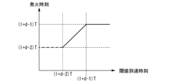
図14は、第l層のi番目のニューロンモデル100aが、第dデータを処理する際のタイミングを示す関数の第2例を示す図である。
図14のグラフの横軸は、第1サブモデル210-1の膜電位が閾値に達する時刻を、ニューラルネットワーク11aへのデータ入力開始時からの経過時間で示す。縦軸は、遅延用サブモデル210fの発火時刻を、ニューラルネットワーク11aへのデータ入力開始時からの経過時間で示す。
FIG. 14 is a diagram showing a second example of a function indicating the timing when the i-
14, the horizontal axis represents the time when the membrane potential of the first sub-model 210-1 reaches the threshold value as the elapsed time from the start of data input to the
図14は、遅延用サブモデル210fによる遅延時間がTよりも短い場合の例を示している。
遅延用サブモデル210fによる遅延時間がTよりも短い場合、出力時間区間内における遅延用サブモデル210fが発火するタイミングが、時間区間内における第1サブモデル210-1が発火するタイミングよりも早くなる。
図14の例で、時刻(l+d-2)Tから(l+d-2+c1)Tまでの間に第1サブモデル210-1の膜電位が閾値に達した場合、遅延用サブモデル210fは、出力時間区間の開始時である時刻(l+d-1)Tに発火する。
FIG. 14 shows an example in which the delay time by the delay sub-model 210f is shorter than T.
When the delay time caused by the delay submodel 210f is shorter than T, the timing at which the delay submodel 210f fires within the output time interval is earlier than the timing at which the first submodel 210-1 fires within the time interval.
In the example of FIG. 14, if the membrane potential of the first submodel 210-1 reaches a threshold between times (l+d-2)T and (l+d-2+c1)T, the delay submodel 210f fires at time (l+d-1)T, which is the start of the output time interval.
また、時刻(l+d-2+c1)Tから(l+d-1)Tまでの間に第1サブモデル210-1の膜電位が閾値に達した場合、遅延用サブモデル210fは、時間T-c1経過後に発火する。時間区間内におけるタイミングで見ると、出力時間区間内における遅延用サブモデル210fが発火するタイミングは、時間区間内における第1サブモデル210-1が発火するタイミングよりも、時間c1だけ早くなる。
このようにタイミングが早まることで、時間区間内におけるスパイク信号の出力タイミングを調整することができる。例えば、データの流れの下流側の層で、スパイク信号の入力が時間区間の最後付近に集中することを回避し得る。
Furthermore, if the membrane potential of the first submodel 210-1 reaches the threshold between times (l+d-2+c1)T and (l+d-1)T, the delay submodel 210f fires after the time T-c1 has elapsed. In terms of timing within the time interval, the timing at which the delay submodel 210f fires within the output time interval is earlier by time c1 than the timing at which the first submodel 210-1 fires within the time interval.
By advancing the timing in this way, it is possible to adjust the output timing of spike signals within a time interval, for example to prevent spike signal inputs from concentrating near the end of a time interval in a downstream layer of the data flow.
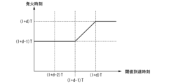
図15は、第l層のi番目のニューロンモデル100aが、第dデータを処理する際のタイミングを示す関数の第3例を示す図である。
図15のグラフの横軸は、第1サブモデル210-1の膜電位が閾値に達する時刻を、ニューラルネットワーク11aへのデータ入力開始時からの経過時間で示す。縦軸は、遅延用サブモデル210fの発火時刻を、ニューラルネットワーク11aへのデータ入力開始時からの経過時間で示す。
FIG. 15 is a diagram showing a third example of a function indicating the timing when the i-
15, the horizontal axis represents the time when the membrane potential of the first sub-model 210-1 reaches the threshold value as the elapsed time from the start of data input to the
図15は、遅延用サブモデル210fによる遅延時間がTよりも長い場合の例を示している。
遅延用サブモデル210fによる遅延時間がTよりも長い場合、出力時間区間内における遅延用サブモデル210fが発火するタイミングが、時間区間内における第1サブモデル210-1が発火するタイミングよりも遅くなる。
FIG. 15 shows an example in which the delay time by the delay sub-model 210f is longer than T.
When the delay time caused by the delay submodel 210f is longer than T, the timing at which the delay submodel 210f fires within the output time interval is later than the timing at which the first submodel 210-1 fires within the time interval.
図15の例で、時刻(l+d-2)Tから(l+d-1-c2)Tまでの間に第1サブモデル210-1の膜電位が閾値に達した場合、遅延用サブモデル210fは、時間T+c2経過後に発火する。時間区間内におけるタイミングで見ると、出力時間区間内における遅延用サブモデル210fが発火するタイミングは、時間区間内における第1サブモデル210-1が発火するタイミングよりも、時間c2だけ遅くなる。
また、時刻(l+d-1-c2)Tから(l+d-1)Tまでの間に第1サブモデル210-1の膜電位が閾値に達した場合、遅延用サブモデル210fは、出力時間区間の終了時である時刻(1+d)Tに発火する。
15, if the membrane potential of the first submodel 210-1 reaches the threshold between times (l+d-2)T and (l+d-1-c2)T, the delay submodel 210f fires after time T+c2 has elapsed. In terms of timing within the time interval, the timing at which the delay submodel 210f fires within the output time interval is later than the timing at which the first submodel 210-1 fires within the time interval by time c2.
Furthermore, if the membrane potential of the first submodel 210-1 reaches a threshold between times (l+d-1-c2)T and (l+d-1)T, the delay submodel 210f fires at time (1+d)T, which is the end of the output time interval.
図16は、ニューラルネットワーク装置のより具体的な構成の第2例を示す図である。
図16に示す構成で、ニューラルネットワーク装置10bは、ニューロンモデル100bを備える。ニューロンモデル100bは、指標値計算部110と、検出部120と、遅延部130bと、信号出力部140と、切替部220bとを備える。
FIG. 16 is a diagram showing a second example of a more specific configuration of a neural network device.
16, the
図16の各部のうち図1の各部に対応して同様の機能を有する部分には同一の符号(110、120、140)を付し、ここでは詳細な説明を省略する。
ニューラルネットワーク装置10bはニューラルネットワーク装置10の例に該当し、ニューロンモデル100bはニューロンモデル100の例に該当する。図16では、ニューロンモデル100bの構成として、図1のニューロンモデル100の構成の遅延部130に代えて遅延部130bが示され、さらに切替部220bが示されている。
16, parts having similar functions to those in FIG. 1 are given the same reference numerals (110, 120, 140), and detailed description thereof will be omitted here.
The
切替部220bは、検出部120からの、膜電位が閾値に達したことを示す信号の伝達先を、2つの遅延部130bの何れかに切り替える。切替部220bでは、膜電位が閾値に達したことを示す信号がスパイク信号に限定されない点で、ニューラルネットワーク装置10aの切替部220aと異なる。膜電位が閾値に達したことを示す信号としてスパイク信号が用いられる場合は、切替部220bは切替部220aと同様である。切替部220aは、切替部220bの例に該当する。切替部220bは、切替手段の例に該当する。
The
遅延部130bは、検出部120からの、膜電位が閾値に達したことを示す信号の入力を受けた時間区間の次の時間区間において、検出部120からの信号の入力を受けたタイミングに応じたタイミングで、発火を指示する信号を信号出力部140へ出力する。
これにより信号出力部140は、上記のように、時間区間のうち第1時間区間内のタイミング、かつ、第1時間区間よりも過去の時間区間である第2時間区間における所定の事象の発生タイミングに応じたタイミングで、スパイク信号を出力する。
遅延部130bは、遅延部130の例に該当する。遅延部130bは、遅延手段の例にも該当する。
The
As a result, the
The
2つの遅延部130bが出力する信号のorをとった信号が、信号出力部140に入力される。したがって、2つの遅延部130bのうち何れが発火を指示する信号を出力した場合も、信号出力部140はスパイク信号を出力する。
遅延部130bがスパイキングニューロンモデルを用いて構成される場合、遅延部130bはサブモデル210と同様である。サブモデル210は、遅延部130bの例に該当する。一方、遅延部130bの構成は、スパイキングニューロンモデルを用いる構成に限定されない。例えば、遅延部130bがタイマを備えて構成され、信号の入力を受けてから信号を出力するまでの時間をタイマを用いて測定するようにしてもよい。
A signal obtained by ORing the signals output by the two
When the
信号出力部140は、遅延部130bからの発火を指示する信号に応じてスパイク信号を出する。遅延部130bからの信号がスパイク信号である場合、信号出力部140が、遅延部130bからのスパイク信号をそのまま出力するようにしてもよい。
検出部120が事象の発生を検出した時刻に所定の遅延時間を加えた時刻が、検出部120が事象の発生を検出した時間区間と同じ時間区間に含まれる場合に、信号出力部140が次の時間区間の開始時にスパイク信号を出力するようにする処理を、遅延部130bが行うようにしてもよいし、信号出力部140が行うようにしてもよい。
The
When the time at which the
検出部120が事象の発生を検出した時刻に所定の遅延時間を加えた時刻が、検出部120が事象の発生を検出した時間区間の次の時間区間よりも遅い時刻になる場合に、信号出力部140が、検出部120が事象の発生を検出した時間区間の次の時間区間の終了時にスパイク信号を出力するようにする処理を、遅延部130bが行うようにしてもよいし、信号出力部140が行うようにしてもよい。
When the time when the
図1に示す構成で、遅延部130が、複数の時刻に信号の入力を受けて、それぞれの時刻から遅延させた時刻に信号を出力可能である。例えば、図16の切替部220bと、2つの遅延部130bとの組み合わせは、遅延部130の例に該当する。
あるいは、遅延部130が、複数の信号を受け入れ可能な経路を備えていてもよい。例えば、遅延部130がシフトレジスタを備え、信号の入力を受けたときにシフトレジスタの再下位ビットを1に設定して所定のクロック周期毎にシフトレジスタをシフトアップさせるようにしてもよい。そして、シフトレジスタの最上位ビット1になったときに、遅延部130が、信号出力部140に対して発火を指示する信号を出力するようにしてもよい。
In the configuration shown in Fig. 1, the
Alternatively, the
図1に示す構成で、検出部120が事象の発生を検出した時刻に所定の遅延時間を加えた時刻が、検出部120が事象の発生を検出した時間区間と同じ時間区間である場合に、信号出力部140が次の時間区間の開始時にスパイク信号を出力するようにする処理を、遅延部130が行うようにしてもよいし、信号出力部140が行うようにしてもよい。
In the configuration shown in FIG. 1, if the time when the
図1に示す構成で、検出部120が事象の発生を検出した時刻に所定の遅延時間を加えた時刻が、検出部120が事象の発生を検出した時間区間の次の時間区間よりも遅い時刻になる場合に、信号出力部140が、検出部120が事象の発生を検出した時間区間の次の時間区間の終了時にスパイク信号を出力するようにする処理を、遅延部130cが行うようにしてもよいし、信号出力部140が行うようにしてもよい。
In the configuration shown in FIG. 1, if the time when the
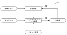
図17は、学習時におけるシステム構成の例を示す図である。図17に示す構成で、ニューラルネットワークシステム1は、ニューラルネットワーク装置10と、学習装置50とを備える。ニューラルネットワーク装置10と学習装置50とが1つの装置として一体的に構成されていてもよい。あるいは、ニューラルネットワーク装置10と学習装置50とが別々の装置として構成されていてもよい。
上述したように、ニューラルネットワーク装置10が構成するニューラルネットワーク11を、ニューラルネットワーク本体とも称する。
Fig. 17 is a diagram showing an example of a system configuration during learning. In the configuration shown in Fig. 17, the
As described above, the
図18は、ニューラルネットワークシステム1における信号の入出力の例を示す図である。
図18の例で、入力データと、その入力データに対する正解を示す教師ラベルとがニューラルネットワークシステム1に入力される。ニューラルネットワーク装置10が入力データの入力を受け、学習装置50が、教師ラベルの入力を受けるようにしてもよい。入力データと教師ラベルとの組み合わせは、教師有り学習における訓練データの例に該当する。
また、ニューラルネットワーク装置10は、クロック信号を取得する。ニューラルネットワーク装置10がクロック回路を備えるようにしてもよい。あるいは、ニューラルネットワーク装置10が、ニューラルネットワーク装置10の外部からのクロック信号の入力を受けるようにしてもよい。
FIG. 18 is a diagram showing an example of signal input and output in the
18, input data and a teacher label indicating a correct answer to the input data are input to the
The
ニューラルネットワーク装置10は、入力データの入力を受けて、その入力データに基づく推定値を出力する。推定値を算出する際、ニューラルネットワーク装置10は、クロック信号を用いて層間の時間区間の同期、および、同一層内のニューロンモデル100間の時間区間の同期をとる。
The
学習装置50は、ニューラルネットワーク装置10の学習を行う。ここでいう学習は、機械学習アルゴリズムによって学習モデルのパラメータ値を調整することである。学習装置50は、ニューロンモデル100に入力されるスパイク信号に対する重み係数の学習を行う。式(4)の重みWij
(l)が、学習装置50が学習によって値を調整する重み係数の例に該当する。
The
学習装置50が、ニューラルネットワーク装置10が出力する推定値と、教師ラベルが示す正解値との誤差に対する評価を示す評価関数を用いて、推定値と正解値との誤差の大きさが小さくなるように、重み係数の学習を行うようにしてもよい。
学習装置50は、学習手段の例に該当する。学習装置50は、例えば、コンピュータを用いて構成される。
The
The
学習装置50が行う学習の手法として、例えば誤差逆伝播法(Backpropagation)などの既存の学習手法を、入力時間区間および出力時間区間が設定されていることに応じてアレンジした手法を用いることができる。
例えば、学習装置50が誤差逆伝播法をアレンジした手法を用いて学習を行う場合、重みWij
(l)を、式(15)で示される変化量ΔWij
(l)だけ変化させるように、重みWij
(l)を更新するようにしてもよい。
The learning method used by the
For example, when the

ηは、学習率を示す定数である。
Cは、式(16)のように表される。
η is a constant indicating the learning rate.
C is expressed as in equation (16).

Cは、ニューラルネットワーク装置10が出力する推定値と、教師ラベルが示す正解値との誤差に対する評価を示す評価関数の例に該当する。Cは、誤差が小さいほど小さい値を出力する損失関数として設定されている。
Mは、出力層(最終層)を示すインデックス値を表す。N(M)は、出力層に含まれるニューロンモデル100の個数を表す。
C corresponds to an example of an evaluation function indicating an evaluation of the error between the estimated value output by the
M represents an index value indicating the output layer (final layer), and N (M) represents the number of
κiは、教師ラベルを表す。ここでは、ニューラルネットワーク装置10が、クラスの個数がN(M)個のクラス分類を行うものとし、教師ラベルがワンホットベクトル(One-hot Vector)で示されるものとする。インデックスiの値が正解クラスを示す場合にκi=1であり、それ以外の場合はκi=0であるものとする。
κ i represents a teacher label. Here, it is assumed that the
t(ref)は、参照スパイク(Reference Spike)を表す。
「γ/2(ti
*(M)-t(ref))2」は、学習困難性を回避するために設けられた項である。この項をテンポラル罰則項(Temporal Penalty Term)とも称する。テンポラル罰則項により、出力層の発火タイミングは参照スパイク周辺に分布することになり、結果として出力ニューロンが安定して発火するようになる。γは、テンポラル罰則項の影響度合いを調整するための定数であり、γ>0である。γをテンポラル罰則係数とも称する。
Siは、ソフトマックス関数であり、式(17)のように表される。
t (ref) represents the Reference Spike.
"γ/2(t i *(M) - t (ref) ) 2 " is a term provided to avoid learning difficulty. This term is also called the temporal penalty term. Due to the temporal penalty term, the firing timing of the output layer is distributed around the reference spike, resulting in stable firing of the output neuron. γ is a constant for adjusting the degree of influence of the temporal penalty term, and γ>0. γ is also called the temporal penalty coefficient.
S i is a softmax function and is expressed as in equation (17).

σsoftは、出力層の発火タイミングが変化したときに、ソフトマックス関数Siの値がどの程度変化するかを調整するためのスケール因子(Scale Factor)として設けられた定数であり、σsoft>0である。このスケール因子が、出力時間区間と同程度(10分の1から10倍程度)の値を持つことで安定した学習が可能になる。
式(17)では、出力層のi番目のスパイク発火時刻ti
*(M)が0≦ti
*(M)≦1で示されるものとする。例えば、出力層のスパイク発火時刻が、クラス毎に、入力データが示す分類対象がそのクラスに分類される確率を示すようにしてもよい。κi=1となるiについて、ti
*(M)の値が1に近いほど「-Σi=1
N(M)(κiln(Si(t*(M))))」の項の値が小さくなり、学習装置50は、損失(評価関数Cの値)を小さく計算する。
ただし、ニューラルネットワーク装置10が行う処理は、クラス分類に限定されない。
σ soft is a constant provided as a scale factor for adjusting the degree to which the value of the softmax function S i changes when the firing timing of the output layer changes, and σ soft > 0. Stable learning becomes possible when this scale factor has a value similar to the output time interval (approximately 1/10 to 10 times).
In formula (17), the i-th spike firing time t i *(M) of the output layer is represented as 0≦t i *(M) ≦1. For example, the spike firing time of the output layer may indicate the probability that the classification object indicated by the input data is classified into that class for each class. For i where κ i =1, the closer the value of t i *(M) is to 1, the smaller the value of the term "-Σ i=1 N(M) (κ i ln(S i (t *(M) )))" becomes, and the
However, the processing performed by the
重みWij
(l)に加えて、あるいは代えて、式(11)に示される重みwfが、学習によって値を調整する重みの対象になっていてもよい。
例えば、重みwfの値がニューロンモデル100毎に設定可能になっていてもよい。この場合の、第l層のi番目のニューロンモデル100における重みwfをwi_f
(l)と表記する。学習装置50が誤差逆伝播法をアレンジした手法を用いて学習を行う場合、重みWi_f
(l)を、式(18)で示される変化量ΔWi_f
(l)だけ変化させるように、重みWi_f
(l)を更新するようにしてもよい。
In addition to or instead of the weights W ij (l) , the weights wf shown in equation (11) may be subject to weighting whose values are adjusted by learning.
For example, the value of the weight wf may be set for each

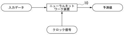
図19は、運用時のニューラルネットワーク装置10における信号の入出力の例を示す図である。
図19に示される運用時と同様、学習時も、ニューラルネットワーク装置10は、入力データの入力を受け、また、クロック信号を取得する。ニューラルネットワーク装置10がクロック回路を備えるようにしてもよい。あるいは、ニューラルネットワーク装置10が、ニューラルネットワーク装置10の外部からのクロック信号の入力を受けるようにしてもよい。
ニューラルネットワーク装置10は、入力データの入力を受けて、その入力データに基づく推定値を出力する。推定値を算出する際、ニューラルネットワーク装置10は、クロック信号を用いて層間の時間区間の同期、および、同一層内のニューロンモデル100間の時間区間の同期をとる。
FIG. 19 is a diagram showing an example of signal input/output in the
19, during learning, the
The
なお、ニューラルネットワーク11の種類は、特定の種類に限定されない。例えば、ニューラルネットワーク11が、スパイキングニューラルネットワークによる畳み込みニューラルネットワーク(Convolutional neural network;CNN)として構成されていてもよい。
The type of
上述したように、ニューラルネットワーク11が順伝播型のスパイキングニューラルネットワークとして構成される場合、ニューラルネットワーク11の層数は2層以上であればよく、特定の層数に限定されない。また、各層が備えるニューロンモデル100の個数は特定の個数に限定されず、各層が1つ以上のニューロンモデル100を備えていればよい。各層が同じ個数のニューロンモデル100を備えていてもよいし、層によって異なる個数のニューロンモデル100を備えていてもよい。また、ニューラルネットワーク11が全結合型になっていてもよいし、全結合型でなくてもよい。
As described above, when the
また、ニューロンモデル100の発火後の膜電位は、上述した電位0から変化しないものに限定されない。例えば、発火から所定時間経過後は、スパイク信号の入力に応じて膜電位が変化するようにしてもよい。ニューロンモデル100の各々の発火回数も、入力データ毎に1回に限定されない。
In addition, the membrane potential after firing of the
スパイキングニューロンモデルとしてのニューロンモデル100の構成も、特定の構成に限定されない。例えば、ニューロンモデル100が、スパイク信号の入力を受けてから次のスパイク信号の入力を受けるまでの変化速度が一定でなくてもよい。
ニューラルネットワーク11の学習方法は、教師あり学習に限定されない。学習装置50が、ニューラルネットワーク11の学習を教師無し学習で行うようにしてもよい。
The configuration of the
The learning method of the
以上のように、指標値計算部110は、時間区間毎に、その時間区間におけるスパイク信号の入力状況に基づいて、スパイク信号出力の指標値である膜電位を時間変化させる。
検出部120は、膜電位に関する所定の事象の発生タイミングを検出する。具体的には、検出部120は、膜電位が閾値に達したタイミング、および、膜電位が閾値に達せずに時間区間が終了するタイミングを検出する。
信号出力部140は、時間区間のうち出力時間区間内のタイミング、かつ、出力時間区間よりも過去の時間区間である入力時間区間における所定の事象の発生タイミングに応じたタイミングで、スパイク信号を出力する。
As described above, the index
The
The
このように、ニューロンモデル100が、時間区間毎にスパイク信号の入力を受け付け、スパイク信号の入力を受けた時間区間の次の時間区間でスパイク信号を出力することで、ニューラルネットワーク11は、時間区間毎にデータの入力を受け付けて、入力された各データを処理することができる。
ニューラルネットワーク装置10によればこの点で、スパイキングニューラルネットワークであるニューラルネットワーク11がデータ処理を効率的に行うことができる。
また、ニューロンモデル100が、スパイク信号の入力を受けた時間区間の次の時間区間でスパイク信号を出力することで、時間区間内におけるスパイク信号の出力タイミングを調整することができる。ニューラルネットワーク装置10では、例えば、ニューラルネットワーク11におけるデータの流れの下流側の層で、スパイク信号の入力が時間区間の最後付近に集中することを回避し得る。
In this way, the
In this respect, according to the
Moreover, the
また、遅延部130は、検出部120が検出する上記のタイミングから所定時間後のタイミングに基づいて、信号出力部140にスパイク信号を出力させるタイミングを決定する。切替部220は、2つの遅延部130のうち前記検出部120の検出結果を入力する遅延部130を、前記時間区間毎に切り替える。
ニューラルネットワーク装置10bでは、2つの遅延部130と切替部220とを用いた比較的簡単な構成で、信号出力部140がスパイク信号を出力する時間区間と、指標値計算部110が次のデータに関するスパイク信号の入力を受ける時間区間とが重なることに対応することができる。
Further, the
The
また、第1検出部212-1が膜電位に関する所定の事象の発生タイミングを検出すると、第1サブモデル210-1が遅延用サブモデル210fへスパイク信号を出力する。遅延用検出部212fは、遅延用信号出力部213fにスパイク信号を出力させるタイミングを、出力時間区間内のタイミング、かつ、入力時間区間にて第1サブモデル210-1からスパイク信号の入力を受けたタイミングから所定時間後のタイミングに基づくタイミングに決定する。 When the first detection unit 212-1 detects the occurrence timing of a specific event related to the membrane potential, the first sub-model 210-1 outputs a spike signal to the delay sub-model 210f. The delay detection unit 212f determines the timing for outputting a spike signal to the delay signal output unit 213f to be within the output time interval and based on a specific time after the spike signal is received from the first sub-model 210-1 in the input time interval.
ニューラルネットワーク装置10aでは、スパイキングニューロンモデルを第1サブモデル210-1および遅延用サブモデル210fとして用いて、ニューロンモデル100aを構成することができる。信号の出力を遅延させる手段をスパイキングニューロンモデルと別に設計する必要が無い点で、設計者がニューラルネットワーク装置10aを設計する負担が比較的軽いことが期待される。また、スパイキングニューロンモデルを多数用いることで、スパイキングニューロンモデルの1個当たりの生産コストが安くなり、ニューラルネットワーク装置10a全体の生産コストが比較的安いことが期待される。
In the
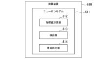
図20は、実施形態に係る演算装置の構成例を示す図である。図20に示す構成で、演算装置610は、ニューロンモデル611を備える。ニューロンモデル611は、指標値計算部612と、検出部613と、信号出力部614とを備える。
かかる構成で、指標値計算部612は、時間区間毎に、その時間区間における信号の入力状況に基づいて信号出力の指標値を変化させる。検出部613は、指標値に関する所定の事象の発生タイミングを検出する。信号出力部614は、時間区間のうち第1時間区間内のタイミング、かつ、第1時間区間よりも過去の時間区間である第2時間区間における所定の事象の発生タイミングに応じたタイミングで、信号を出力する。
指標値計算部612は、指標値計算手段の例に該当する。検出部613は、検出手段の例に該当する。信号出力部614は、信号出力手段の例に該当する。
Fig. 20 is a diagram showing an example of the configuration of a calculation device according to an embodiment. In the configuration shown in Fig. 20, a
In this configuration, the index
The index
このように、ニューロンモデル611が、時間区間毎にスパイク信号の入力を受け付け、スパイク信号の入力を受けた時間区間の次の時間区間でスパイク信号を出力することで、ニューロンモデル611を用いるスパイキングニューラルネットワークとして機能する演算装置610は、時間区間毎にデータの入力を受け付けて、入力された各データを処理することができる。
演算装置610によればこの点で、スパイキングニューラルネットワークがデータ処理を効率的に行うことができる。
In this way, the
In this respect, the
また、ニューロンモデル611が、スパイク信号の入力を受けた時間区間の次の時間区間でスパイク信号を出力することで、時間区間内におけるスパイク信号の出力タイミングを調整することができる。演算装置610では、例えば、スパイキングニューラルネットワークにおけるデータの流れの下流側の層で、スパイク信号の入力が時間区間の最後付近に集中することを回避し得る。
In addition, the
図21は、実施形態に係るニューラルネットワークシステムの構成例を示す図である。
図21に示す構成で、ニューラルネットワークシステム620は、ニューラルネットワーク本体621と、学習部626とを備える。ニューラルネットワーク本体621は、ニューロンモデル622を備える。ニューロンモデル622は、指標値計算部623と、検出部624と、信号出力部625とを備える。
FIG. 21 is a diagram illustrating an example of the configuration of a neural network system according to the embodiment.
21 , a
かかる構成で、指標値計算部623は、時間区間毎に、その時間区間における信号の入力状況に基づいて信号出力の指標値を変化させる。検出部624は、指標値に関する所定の事象の発生タイミングを検出する。信号出力部625は、時間区間のうち第1時間区間内のタイミング、かつ、第1時間区間よりも過去の時間区間である第2時間区間における所定の事象の発生タイミングに応じたタイミングで、信号を出力する。学習部626は、信号に対する重み係数の学習を行う。
In this configuration, the index
指標値計算部623は、指標値計算手段の例に該当する。信号出力部625は、信号出力手段の例に該当する。学習部626は、学習手段の例に該当する。
ニューラルネットワークシステム620では、これにより、学習によって重み係数を調整することができ、ニューラルネットワーク本体621による推定精度を向上させることができる。
The index
This allows the
図22は、実施形態に係るニューロンモデル装置の構成例を示す図である。図22に示す構成で、ニューロンモデル装置630は、指標値計算部631と、検出部632と、信号出力部633とを備える。
かかる構成で、指標値計算部631は、時間区間毎に、その時間区間におけるスパイク信号の入力状況に基づいてスパイク信号出力の指標値を変化させる。検出部632は、指標値に関する所定の事象の発生タイミングを検出する。信号出力部633は、時間区間のうち第1時間区間内のタイミング、かつ、前記第1時間区間よりも過去の時間区間である第2時間区間における前記所定の事象の発生タイミングに応じたタイミングで、スパイク信号を出力する。
22 is a diagram showing an example of the configuration of a neuron model device according to an embodiment. In the configuration shown in FIG. 22, a
With this configuration, the index
このように、ニューロンモデル装置630が信号の入力を受け付ける入力時間区間、および、ニューロンモデル装置630がスパイク信号を出力する出力時間区間を設定することで、指標値計算部631が指標値を計算するべき時間を、入力時間区間の開始時から出力時間区間の終了時までの時間に限定することができる。他の時間では、ニューロンモデル装置630は、他のデータに対する処理を行うことができる。
ニューロンモデル装置630によれば、この点で、スパイキングニューラルネットワークがデータ処理を効率的に行うことができる。
In this way, by setting the input time interval during which the
In this respect, the
また、ニューロンモデル装置630が、スパイク信号の入力を受けた時間区間の次の時間区間でスパイク信号を出力することで、時間区間内におけるスパイク信号の出力タイミングを調整することができる。ニューロンモデル装置630によれば、例えば、スパイキングニューラルネットワークにおけるデータの流れの下流側の層で、スパイク信号の入力が時間区間の最後付近に集中することを回避し得る。
In addition, the
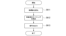
図23は、実施形態に係る演算方法における処理手順の例を示すフローチャートである。図23に示す演算方法は、指標値を変化させること(ステップS611)と、事象発生タイミングを検出すること(ステップS612)と、信号を出力すること(ステップS613)とを含む。
指標値を変化させること(ステップS611)では、時間区間毎に、その時間区間における信号の入力状況に基づいて信号出力の指標値を変化させる。事象発生タイミングを検出すること(ステップS612)では、指標値に関する所定の事象の発生タイミングを検出する。信号を出力すること(ステップS613)では、時間区間のうち第1時間区間内のタイミング、かつ、第1時間区間よりも過去の時間区間である第2時間区間における前記所定の事象の発生タイミングに応じたタイミングで、信号を出力する。
23 is a flowchart showing an example of a processing procedure in a calculation method according to an embodiment. The calculation method shown in FIG. 23 includes changing an index value (step S611), detecting an event occurrence timing (step S612), and outputting a signal (step S613).
In changing the index value (step S611), the index value of the signal output is changed for each time interval based on the input state of the signal in that time interval. In detecting the event occurrence timing (step S612), the occurrence timing of a predetermined event related to the index value is detected. In outputting the signal (step S613), the signal is output at a timing within a first time interval of the time interval and at a timing corresponding to the occurrence timing of the predetermined event in a second time interval that is an earlier time interval than the first time interval.
図23に示す演算方法で、時間区間毎にスパイク信号の入力を受け付け、スパイク信号の入力を受けた時間区間の次の時間区間でスパイク信号を出力することで、スパイキングニューラルネットワークは、時間区間毎にデータの入力を受け付けて、入力された各データを処理することができる。
図23に示す演算方法によればこの点で、スパイキングニューラルネットワークがデータ処理を効率的に行うことができる。
In the calculation method shown in FIG. 23, a spike signal is input for each time interval, and a spike signal is output in the time interval following the time interval in which the spike signal was input. This allows the spiking neural network to receive data input for each time interval and process each piece of input data.
In this respect, the calculation method shown in FIG. 23 allows the spiking neural network to process data efficiently.
また、図23に示す演算方法では、スパイク信号の入力を受けた時間区間の次の時間区間でスパイク信号を出力することで、時間区間内におけるスパイク信号の出力タイミングを調整することができる。図23に示す演算方法によれば、例えば、スパイキングニューラルネットワークにおけるデータの流れの下流側の層で、スパイク信号の入力が時間区間の最後付近に集中することを回避し得る。 In addition, the calculation method shown in FIG. 23 can adjust the output timing of the spike signal within a time interval by outputting the spike signal in the time interval following the time interval in which the spike signal was input. The calculation method shown in FIG. 23 can prevent spike signal inputs from concentrating near the end of a time interval, for example, in a downstream layer of the data flow in a spiking neural network.
図24は、少なくとも1つの実施形態に係るコンピュータの構成を示す概略ブロック図である。
図24に示す構成で、コンピュータ700は、CPU710と、主記憶装置720と、補助記憶装置730と、インタフェース740と、不揮発性記録媒体750とを備える。
FIG. 24 is a schematic block diagram illustrating a configuration of a computer according to at least one embodiment.
In the configuration shown in FIG. 24, a
上記のニューラルネットワーク装置10、学習装置50、演算装置610、ニューラルネットワークシステム620、および、ニューロンモデル装置630のうち何れか1つ以上またはその一部が、コンピュータ700に実装されてもよい。その場合、上述した各処理部の動作は、プログラムの形式で補助記憶装置730に記憶されている。CPU710は、プログラムを補助記憶装置730から読み出して主記憶装置720に展開し、当該プログラムに従って上記処理を実行する。また、CPU710は、プログラムに従って、上述した各記憶部に対応する記憶領域を主記憶装置720に確保する。各装置と他の装置との通信は、インタフェース740が通信機能を有し、CPU710の制御に従って通信を行うことで実行される。
Any one or more of the above-mentioned
ニューラルネットワーク装置10がコンピュータ700に実装される場合、ニューラルネットワーク装置10およびその各部の動作は、プログラムの形式で補助記憶装置730に記憶されている。CPU710は、プログラムを補助記憶装置730から読み出して主記憶装置720に展開し、当該プログラムに従って上記処理を実行する。
When the
また、CPU710は、プログラムに従って、ニューラルネットワーク装置10の処理のための記憶領域を主記憶装置720に確保する。ニューラルネットワーク装置10と他の装置との通信は、インタフェース740が通信機能を有し、CPU710の制御に従って動作することで実行される。ニューラルネットワーク装置10とユーザとのインタラクションは、インタフェース740が表示装置および入力デバイスを備え、CPU710の制御に従って各種画像の表示を行い、ユーザ操作を受け付けることで実行される。
The
学習装置50がコンピュータ700に実装される場合、学習装置50の動作は、プログラムの形式で補助記憶装置730に記憶されている。CPU710は、プログラムを補助記憶装置730から読み出して主記憶装置720に展開し、当該プログラムに従って上記処理を実行する。
When the
また、CPU710は、プログラムに従って、学習装置50の処理のための記憶領域を主記憶装置720に確保する。学習装置50と他の装置との通信は、インタフェース740が通信機能を有し、CPU710の制御に従って動作することで実行される。学習装置50とユーザとのインタラクションは、インタフェース740が表示装置および入力デバイスを備え、CPU710の制御に従って各種画像の表示を行い、ユーザ操作を受け付けることで実行される。
The
演算装置610がコンピュータ700に実装される場合、演算装置610およびその各部の動作は、プログラムの形式で補助記憶装置730に記憶されている。CPU710は、プログラムを補助記憶装置730から読み出して主記憶装置720に展開し、当該プログラムに従って上記処理を実行する。
When the
また、CPU710は、プログラムに従って、演算装置610の処理のための記憶領域を主記憶装置720に確保する。演算装置610と他の装置との通信は、インタフェース740が通信機能を有し、CPU710の制御に従って動作することで実行される。演算装置610とユーザとのインタラクションは、インタフェース740が表示装置および入力デバイスを備え、CPU710の制御に従って各種画像の表示を行い、ユーザ操作を受け付けることで実行される。
The
ニューラルネットワークシステム620がコンピュータ700に実装される場合、ニューラルネットワークシステム620およびその各部の動作は、プログラムの形式で補助記憶装置730に記憶されている。CPU710は、プログラムを補助記憶装置730から読み出して主記憶装置720に展開し、当該プログラムに従って上記処理を実行する。
When the
また、CPU710は、プログラムに従って、ニューラルネットワークシステム620の処理のための記憶領域を主記憶装置720に確保する。ニューラルネットワークシステム620と他の装置との通信は、インタフェース740が通信機能を有し、CPU710の制御に従って動作することで実行される。ニューラルネットワークシステム620とユーザとのインタラクションは、インタフェース740が表示装置および入力デバイスを備え、CPU710の制御に従って各種画像の表示を行い、ユーザ操作を受け付けることで実行される。
The
なお、ニューラルネットワーク装置10、学習装置50、演算装置610、ニューラルネットワークシステム620、および、ニューロンモデル装置630が行う処理の全部または一部を実行するためのプログラムをコンピュータ読み取り可能な記録媒体に記録して、この記録媒体に記録されたプログラムをコンピュータシステムに読み込ませ、実行することにより各部の処理を行ってもよい。なお、ここでいう「コンピュータシステム」とは、OSや周辺機器等のハードウェアを含むものとする。
また、「コンピュータ読み取り可能な記録媒体」とは、フレキシブルディスク、光磁気ディスク、ROM(Read Only Memory)、CD-ROM(Compact Disc Read Only Memory)等の可搬媒体、コンピュータシステムに内蔵されるハードディスク等の記憶装置のことをいう。また上記プログラムは、前述した機能の一部を実現するためのものであってもよく、さらに前述した機能をコンピュータシステムにすでに記録されているプログラムとの組み合わせで実現できるものであってもよい。
In addition, the
Furthermore, the term "computer-readable recording medium" refers to portable media such as flexible disks, optical magnetic disks, ROMs (Read Only Memory), and CD-ROMs (Compact Disc Read Only Memory), as well as storage devices such as hard disks built into computer systems. The above-mentioned program may be for realizing part of the above-mentioned functions, or may be capable of realizing the above-mentioned functions in combination with a program already recorded in the computer system.
以上、この発明の実施形態について図面を参照して詳述してきたが、具体的な構成はこの実施形態に限られるものではなく、この発明の要旨を逸脱しない範囲の設計等も含まれる。 The above describes an embodiment of the present invention in detail with reference to the drawings, but the specific configuration is not limited to this embodiment, and includes designs that do not deviate from the gist of the present invention.
1、620 ニューラルネットワークシステム
10 ニューラルネットワーク装置
11 ニューラルネットワーク
50 学習装置
100、611、622 ニューロンモデル
110、211、612、623、631 指標値計算部
120、212、613、624、632 検出部
130、130b 遅延部
140、213、614、625、633 信号出力部
210 サブモデル
210f 遅延用サブモデル
210-1 第1サブモデル
210-2 第2サブモデル
210-3 第3サブモデル
211f 遅延用指標値計算部
211-1 第1指標値計算部
211-2 第2指標値計算部
211-3 第3指標値計算部
212f 遅延用検出部
212-1 第1検出部
212-2 第2検出部
212-3 第3検出部
213f 遅延用信号出力部
213-1 第1信号出力部
213-2 第2信号出力部
213-3 第3信号出力部
220a、220b 切替部
221、231 スイッチ
230 統合部
232 インバータ
610 演算装置
621 ニューラルネットワーク本体
626 学習部
630 ニューロンモデル装置
1, 620
Claims (7)
前記指標値に関する所定の事象の発生タイミングを検出する検出手段と、
前記時間区間のうち第1時間区間内のタイミング、かつ、前記第1時間区間よりも過去の時間区間である第2時間区間における前記所定の事象の発生タイミングに応じたタイミングで、信号を出力する信号出力手段と、
を備えるスパイキングニューロンモデル
を備える演算装置。 an index value calculation means for changing an index value of a signal output for each time interval based on the input state of the signal in that time interval;
A detection means for detecting the occurrence timing of a predetermined event related to the index value;
a signal output means for outputting a signal at a timing within a first time period of the time period and at a timing corresponding to an occurrence timing of the predetermined event in a second time period that is a time period earlier than the first time period;
A computing device comprising a spiking neuron model comprising:
2つの前記遅延手段のうち前記タイミングを決定させる前記遅延手段を、前記時間区間毎に切り替える切替手段と、
をさらに備える、
請求項1に記載の演算装置。 a delay means for determining a timing for causing the signal output means to output a signal based on a timing a predetermined time after the timing detected by the detection means;
a switching means for switching one of the two delay means which determines the timing for each of the time intervals;
Further comprising:
The computing device of claim 1 .
前記検出手段が前記所定の事象の発生タイミングを検出すると、前記第1スパイキングニューロンモデルが前記第2スパイキングニューロンモデルへ前記信号を出力し、
前記遅延手段は、前記信号出力手段に前記信号を出力させるタイミングを、前記第1時間区間内のタイミング、かつ、前記第2時間区間にて前記第1スパイキングニューロンモデルから前記信号の入力を受けたタイミングから所定時間後のタイミングに基づくタイミングに決定する、
請求項2に記載の演算装置。 a first spiking neuron model including the index value calculation means and the detection means, and two second spiking neuron models including the delay means and the signal output means;
when the detection means detects the occurrence timing of the predetermined event, the first spiking neuron model outputs the signal to the second spiking neuron model;
the delay means determines a timing for causing the signal output means to output the signal to be a timing within the first time interval and based on a timing a predetermined time after a timing of receiving the input of the signal from the first spiking neuron model in the second time interval;
The computing device according to claim 2 .
前記スパイキングニューラルネットワーク本体は、
時間区間毎に、その時間区間における信号の入力状況に基づいて信号出力の指標値を変化させる指標値計算手段と、
前記指標値に関する所定の事象の発生タイミングを検出する検出手段と、
前記時間区間のうち第1時間区間内のタイミング、かつ、前記第1時間区間よりも過去の時間区間である第2時間区間における前記所定の事象の発生タイミングに応じたタイミングで、信号を出力する信号出力手段と、
を備えるスパイキングニューロンモデルを備え、
前記学習手段は、前記信号に対する重み係数の学習を行う、
ニューラルネットワークシステム。 The present invention comprises a spiking neural network main body and a learning means,
The spiking neural network body includes:
an index value calculation means for changing an index value of a signal output for each time interval based on the input state of the signal in that time interval;
A detection means for detecting the occurrence timing of a predetermined event related to the index value;
a signal output means for outputting a signal at a timing within a first time period of the time period and at a timing corresponding to an occurrence timing of the predetermined event in a second time period that is a time period earlier than the first time period;
A spiking neuron model comprising:
The learning means learns a weighting factor for the signal.
Neural network system.
前記指標値に関する所定の事象の発生タイミングを検出する検出手段と、
前記時間区間のうち第1時間区間内のタイミング、かつ、前記第1時間区間よりも過去の時間区間である第2時間区間における前記所定の事象の発生タイミングに応じたタイミングで、信号を出力する信号出力手段と、
を備えるニューロンモデル装置。 an index value calculation means for changing an index value of a signal output for each time interval based on the input state of the signal in that time interval;
A detection means for detecting the occurrence timing of a predetermined event related to the index value;
a signal output means for outputting a signal at a timing within a first time period of the time period and at a timing corresponding to an occurrence timing of the predetermined event in a second time period that is a time period earlier than the first time period;
A neuron model device comprising:
前記指標値に関する所定の事象の発生タイミングを検出することと、
前記時間区間のうち第1時間区間内のタイミング、かつ、前記第1時間区間よりも過去の時間区間である第2時間区間における前記所定の事象の発生タイミングに応じたタイミングで、信号を出力することと、
を含む演算方法。 changing an index value of a signal output for each time interval based on an input state of the signal in that time interval;
Detecting occurrence timing of a predetermined event related to the index value;
outputting a signal at a timing within a first time interval of the time period and at a timing corresponding to an occurrence timing of the predetermined event in a second time interval that is a time interval earlier than the first time interval;
A calculation method including:
時間区間毎に、その時間区間における信号の入力状況に基づいて信号出力の指標値を変化させることと、
前記指標値に関する所定の事象の発生タイミングを検出することと、
前記時間区間のうち第1時間区間内のタイミング、かつ、前記第1時間区間よりも過去の時間区間である第2時間区間における前記所定の事象の発生タイミングに応じたタイミングで、信号を出力することと、
を実行させるためのプログラム。 Programmable devices,
changing an index value of a signal output for each time interval based on an input state of the signal in that time interval;
Detecting occurrence timing of a predetermined event related to the index value;
outputting a signal at a timing within a first time interval of the time period and at a timing corresponding to an occurrence timing of the predetermined event in a second time interval that is a time interval earlier than the first time interval;
A program for executing.
Priority Applications (2)
| Application Number | Priority Date | Filing Date | Title |
|---|---|---|---|
| JP2021130005A JP7694246B2 (en) | 2021-08-06 | 2021-08-06 | Arithmetic device, neural network system, neuron model device, arithmetic method, and program |
| US17/872,096 US20230043618A1 (en) | 2021-08-06 | 2022-07-25 | Computation apparatus, neural network system,neuron model apparatus, computation method and program |
Applications Claiming Priority (1)
| Application Number | Priority Date | Filing Date | Title |
|---|---|---|---|
| JP2021130005A JP7694246B2 (en) | 2021-08-06 | 2021-08-06 | Arithmetic device, neural network system, neuron model device, arithmetic method, and program |
Publications (2)
| Publication Number | Publication Date |
|---|---|
| JP2023023995A JP2023023995A (en) | 2023-02-16 |
| JP7694246B2 true JP7694246B2 (en) | 2025-06-18 |
Family
ID=85152883
Family Applications (1)
| Application Number | Title | Priority Date | Filing Date |
|---|---|---|---|
| JP2021130005A Active JP7694246B2 (en) | 2021-08-06 | 2021-08-06 | Arithmetic device, neural network system, neuron model device, arithmetic method, and program |
Country Status (2)
| Country | Link |
|---|---|
| US (1) | US20230043618A1 (en) |
| JP (1) | JP7694246B2 (en) |
Families Citing this family (1)
| Publication number | Priority date | Publication date | Assignee | Title |
|---|---|---|---|---|
| CA3178441A1 (en) | 2022-10-05 | 2024-04-05 | Wilten Nicola | Data transmission between devices |
Citations (1)
| Publication number | Priority date | Publication date | Assignee | Title |
|---|---|---|---|---|
| WO2020013069A1 (en) | 2018-07-13 | 2020-01-16 | ソニー株式会社 | Multiply-accumulate device, multiply-accumulate circuit, multiply-accumulate system, and multiply-accumulate method |
-
2021
- 2021-08-06 JP JP2021130005A patent/JP7694246B2/en active Active
-
2022
- 2022-07-25 US US17/872,096 patent/US20230043618A1/en active Pending
Patent Citations (1)
| Publication number | Priority date | Publication date | Assignee | Title |
|---|---|---|---|---|
| WO2020013069A1 (en) | 2018-07-13 | 2020-01-16 | ソニー株式会社 | Multiply-accumulate device, multiply-accumulate circuit, multiply-accumulate system, and multiply-accumulate method |
Also Published As
| Publication number | Publication date |
|---|---|
| JP2023023995A (en) | 2023-02-16 |
| US20230043618A1 (en) | 2023-02-09 |
Similar Documents
| Publication | Publication Date | Title |
|---|---|---|
| KR102850048B1 (en) | Model training method and apparatus, and data recognizing method | |
| US10032498B2 (en) | Memory cell unit and recurrent neural network including multiple memory cell units | |
| KR102492318B1 (en) | Model training method and apparatus, and data recognizing method | |
| KR102032146B1 (en) | Artificial neural network using piecewise linear rectification unit for compensating defect of element | |
| CN109190537A (en) | A kind of more personage's Attitude estimation methods based on mask perceived depth intensified learning | |
| US11182676B2 (en) | Cooperative neural network deep reinforcement learning with partial input assistance | |
| US11531879B1 (en) | Iterative transfer of machine-trained network inputs from validation set to training set | |
| US20100082126A1 (en) | Control device, control program, and control method | |
| KR20200128938A (en) | Model training method and apparatus, and data recognizing method | |
| US11790232B2 (en) | Method and apparatus with neural network data input and output control | |
| US20180277143A1 (en) | Method and apparatus for training acoustic model | |
| JP7694246B2 (en) | Arithmetic device, neural network system, neuron model device, arithmetic method, and program | |
| CN112633463A (en) | Dual recurrent neural network architecture for modeling long term dependencies in sequence data | |
| CN115204350A (en) | Training method and training device for impulse neural network | |
| KR20220063476A (en) | Architecture for generating qa pairs from contexts | |
| JP7725928B2 (en) | Arithmetic device, neural network system, neuron model device, arithmetic method and program | |
| JP2020057357A (en) | Operating method and training method of neural network, and neural network thereof | |
| JP7047283B2 (en) | Information processing equipment, methods, and programs | |
| US11568303B2 (en) | Electronic apparatus and control method thereof | |
| JP7589818B2 (en) | Arithmetic device, neural network system, neuron model device, arithmetic method, and program | |
| Isomura et al. | Accurate connection strength estimation based on variational bayes for detecting synaptic plasticity | |
| WO2023032158A1 (en) | Computing device, neural network system, neuron model device, computation method, and trained model generation method | |
| JP7613603B2 (en) | Arithmetic device, neural network system, neuron model device, arithmetic method, and trained model generating method | |
| JP7597407B2 (en) | Apparatus and method for integrated search of artificial neural network and computation accelerator structure considering hard constraints | |
| US11126912B2 (en) | Realigning streams of neuron outputs in artificial neural network computations |
Legal Events
| Date | Code | Title | Description |
|---|---|---|---|
| RD01 | Notification of change of attorney |
Free format text: JAPANESE INTERMEDIATE CODE: A7421 Effective date: 20240408 |
|
| A621 | Written request for application examination |
Free format text: JAPANESE INTERMEDIATE CODE: A621 Effective date: 20240704 |
|
| TRDD | Decision of grant or rejection written | ||
| A01 | Written decision to grant a patent or to grant a registration (utility model) |
Free format text: JAPANESE INTERMEDIATE CODE: A01 Effective date: 20250507 |
|
| A61 | First payment of annual fees (during grant procedure) |
Free format text: JAPANESE INTERMEDIATE CODE: A61 Effective date: 20250520 |
|
| R150 | Certificate of patent or registration of utility model |
Ref document number: 7694246 Country of ref document: JP Free format text: JAPANESE INTERMEDIATE CODE: R150 |