JP7689727B2 - Display device for monitor system - Google Patents
Display device for monitor system Download PDFInfo
- Publication number
- JP7689727B2 JP7689727B2 JP2021143690A JP2021143690A JP7689727B2 JP 7689727 B2 JP7689727 B2 JP 7689727B2 JP 2021143690 A JP2021143690 A JP 2021143690A JP 2021143690 A JP2021143690 A JP 2021143690A JP 7689727 B2 JP7689727 B2 JP 7689727B2
- Authority
- JP
- Japan
- Prior art keywords
- blood
- data
- system data
- carbon dioxide
- patient
- Prior art date
- Legal status (The legal status is an assumption and is not a legal conclusion. Google has not performed a legal analysis and makes no representation as to the accuracy of the status listed.)
- Active
Links
Images


Landscapes
- Measurement Of The Respiration, Hearing Ability, Form, And Blood Characteristics Of Living Organisms (AREA)
Description
本発明は、血液の体外循環に移行する前、体外循環中、及び体外循環後の患者の状態を監視するモニタシステムの表示装置に関する。 The present invention relates to a display device for a monitoring system that monitors the condition of a patient before, during, and after extracorporeal blood circulation.
特許文献1には、表示装置を備えるモニタシステムが記載されている。この表示装置は、CO2ガスの排泄量、混合呼気濃度、肺胞換気量、死腔量、及び肺胞気濃度の数値表を表示する。 Patent Document 1 describes a monitor system equipped with a display device that displays a table of numerical values of the excretion amount, mixed exhaled breath concentration, alveolar ventilation volume, dead space volume, and alveolar gas concentration of CO2 gas.
患者の血液の体外循環は、心肺機能の補助及び心肺機能の代行を目的に実施される。そのため、適切且つ安全な体外循環を行うためには、患者の状態を示す様々なパラメータの監視が必要となる。特に、管理が大変なVV-ECMO(Veno-Venous Extra Corporeal Membrane Oxygenation)を実施する際は、患者の生体肺の状態監視と人工肺による血液の酸素化の監視とが必要となる。例えば、血液ガスモニターを使用することによって、血液ガスのパラメータによって示される人工肺による血液の酸素化を監視できる。しかし、血液ガスモニターでは、生体肺の状態を示すパラメータを監視できない。 Extracorporeal circulation of a patient's blood is performed for the purpose of assisting and substituting for cardiopulmonary function. Therefore, in order to perform appropriate and safe extracorporeal circulation, it is necessary to monitor various parameters that indicate the patient's condition. In particular, when performing VV-ECMO (Veno-Venous Extra Corporeal Membrane Oxygenation), which is difficult to manage, it is necessary to monitor the condition of the patient's vital lungs and the oxygenation of blood by the artificial lung. For example, by using a blood gas monitor, it is possible to monitor the oxygenation of blood by the artificial lung, which is indicated by blood gas parameters. However, a blood gas monitor cannot monitor parameters that indicate the condition of the vital lungs.
本発明の一態様に係る表示装置は、患者の状態を監視するためのモニタシステムの表示装置であって、前記患者の呼吸に関連する呼吸系データと、前記患者の血液に関連する血液系データとを表示する表示部と、前記呼吸系データと前記血液系データとが同時に表示されるように、前記表示部を制御する表示制御部とを備える。 A display device according to one aspect of the present invention is a display device of a monitor system for monitoring the condition of a patient, and includes a display unit that displays respiratory system data related to the patient's breathing and blood system data related to the patient's blood, and a display control unit that controls the display unit so that the respiratory system data and the blood system data are displayed simultaneously.
これにより、一つの画面において呼吸系データと血液系データを監視できるので、体外循環が必要な患者の管理が容易となる。 This allows respiratory and blood system data to be monitored on a single screen, making it easier to manage patients who require extracorporeal circulation.
本発明のさらなる特徴は、添付図面を参照して例示的に示した以下の実施例の説明から明らかになる。 Further features of the present invention will become apparent from the following description of the embodiments, given by way of example only with reference to the accompanying drawings.
以下、本発明を実施するための例示的な実施形態を、図面を参照して詳細に説明する。ただし、以下の実施形態において説明する寸法、材料、形状及び構成要素の相対的な位置は任意に設定でき、本発明が適用される装置の構成又は様々な条件に応じて変更できる。また、特別な記載がない限り、本発明の範囲は、以下に具体的に記載された実施形態に限定されない。 Below, exemplary embodiments for carrying out the present invention will be described in detail with reference to the drawings. However, the dimensions, materials, shapes, and relative positions of components described in the following embodiments can be set arbitrarily and can be changed according to the configuration of the device to which the present invention is applied or various conditions. Furthermore, unless otherwise specified, the scope of the present invention is not limited to the embodiments specifically described below.
[第1実施形態]
図1に示すモニタシステム300は、体外循環に移行する前、体外循環中、及び体外循環後の患者の状態を監視するために用いられる。モニタシステム300は、表示装置30と、患者Pの血液の体外循環を行う体外循環システム100と、呼吸補助システム200とを備えている。例えば、呼吸補助システム200は、人工呼吸器又は吸入麻酔システム等であり、図1の例では人工呼吸器が設けられている。ただし、モニタシステム300は、体外循環システム100及び呼吸補助システム200の少なくとも一方から表示装置30に表示させるデータを取得してもよい。この場合、モニタシステム300は、体外循環システム100及び呼吸補助システム200を備えていなくともよい。さらに、モニタシステム300は、外部の医療用装置から表示装置30に表示させるデータを取得してもよい。
[First embodiment]
The
[体外循環システム100]
例えば、体外循環システム100は、患者Pの血液の循環動作と、血液に対する酸素の付加及び二酸化炭素の除去とを行う。そのために、体外循環システム100は、脱血回路の一例である脱血ライン112と、血液を移送する送血回路の一例である送血ライン113とを備えている。また、体外循環システム100は、送血ライン113を介して送血側血液を患者Pの体内へ送血する送血ポンプ114を備えている。さらに、体外循環システム100は、血液中の二酸化炭素を排出して血液に酸素を付加する人工肺115を備えている。
[Extracorporeal Circulation System 100]
For example, the
脱血ライン112には、患者の血液に関連する血液系データを検出する脱血側センサS1が設けられている。例えば、血液系データは、血液の体外循環の過程で得られるデータであり、酸素分圧及び二酸化炭素分圧等が含まれる。また、送血ライン113には、血液系データを検出する送血側センサS2が設けられている。さらに、体外循環システム100は、不図示の循環制御装置を備えており、循環制御装置は体外循環システム100の全体を制御する。そして、体外循環システム100を構成する各部から血液系データ(例えば、スイープガスの圧力等)が、循環制御装置によって取得される。例えば、脱血側センサS1は、脱血ライン112を流れる脱血側血液から検出した血液系データを循環制御装置へ送信する。また、送血側センサS2は、送血ライン113を流れる送血側血液から検出した血液系データを循環制御装置へ送信する。
The
なお、体外循環システム100は、患者Pから血液系データを検出する他の検出装置をさらに備えていてもよい。一例として、当該他の検出装置はパルスオキシメータであり、経皮的動脈血酸素飽和度を検出する。制御部32は、不図示の記憶部を備えており、生体肺の酸素消費量及び二酸化炭素生産量と、人工肺115の酸素消費量及び二酸化炭素生産量とを、検出又は算出した時刻と関連付けて記憶する。なお、それぞれの時刻は、同一の時間軸で表示できるように同期されている。
The
脱血ライン112には、脱血流量調整部(不図示)が設けられている。この脱血流量調整部は、送血ポンプ114のモータの回転数によって脱血流量を調整する。具体的には、モータの回転数が上がると脱血流量が増加し、モータの回転数が下がると脱血流量が減少する。代替的に、脱血流量調整部は、クランプ部材及びその駆動部を有していてもよい。手動により又はモータ等の駆動部の駆動力により、脱血流量調整部のクランプ量(挟込量)を調整できる。これにより、脱血ライン112の断面積を変化させて、脱血ライン112を流れる脱血流量を調整できる。また、送血ライン113に送血流量調整部が設けられていてもよい。この送血流量調整部は、一例としてクランプ部材であり、手動により、又はクランプ部材に接続されたモータからの駆動力により、クランプ量を調整できる。これにより、送血ライン113の断面積を変化させて、送血ライン113を流れる送血流量を調整できる。
The
送血ポンプ114は、モータによりインペラ羽根を回転させて、人工肺115に送血する遠心ポンプである。また、送血ポンプ114のモータは、循環制御装置から出力される制御信号によって回転数が制御される。そして、送血ポンプ114は、増減される回転数に応じた流量の血液を送血する。代替的に、送血ポンプ114は、回転ローラがチューブを押し潰しながら回転移動することにより、チューブ内の血液を吸引及び押し出すローラポンプであってもよい。
The
人工肺115は、例えば、気体透過性に優れた中空糸膜又は平膜等を備えており、血液中の二酸化炭素を排出して酸素を付加する。また、人工肺115は、血液の温度を調整するための熱交換部を有している。具体的に、患者Pの体外に脱血又は誘導された酸素付加前の静脈血は、人工肺115へ送血される。そして、人工肺115は、静脈血から熱交換部の外周に配置されたフィルタによって、気泡を分離する。その後、人工肺115は、熱交換部によって静脈血を温調する。さらに、人工肺115は、ガス交換部によって、ガス交換エレメントを介して静脈血を動脈血化する。すなわち、人工肺115は、酸素を付加し且つ二酸化炭素を除去する。そして、人工肺115は、ガス交換部の内周に配置されたフィルタによって、酸素付加後の動脈血から凝固塊を分離する。その後、動脈血は、送血ライン113を通って患者Pへと送血される。なお、体外循環システム100には、体外循環される血液中の気泡、異物及び白血球を除去するためのラインフィルタが設けられてもよい。
The
人工肺115は、ガス供給部(不図示)に接続されており、ガス供給部から医療用ガスが人工肺115に供給される。この医療用ガスは、酸素及び空気からなる混合ガスであり、必要に応じて二酸化炭素がさらに加えられる。ガス供給部においては、血液系データとして医療用ガスの流量が検出される。また、人工肺115には温度プローブが設けられており、血液系データとして温度データが循環制御装置に送信される。また、人工肺115に流入及び流出するガスを分析するガス分析器(不図示)が設けられていてもよい。例えば、ガス分析器は、血液系データとして流入ガス及び流出ガスの酸素濃度並びに二酸化炭素濃度を、血液系データとして検出する。そして、ガス分析器は、検出した酸素濃度並びに二酸化炭素濃度を循環制御装置に送信する。
The
[呼吸補助システム200]
呼吸補助システム200は、操作パネル、ガス供給部、ガス混合部、及び圧力調整部等を備える本体部201と、本体部201から患者に酸素及び空気の混合ガスを送気するための呼吸回路202と、混合ガスを加湿するための加湿部203とを備えている。また、本体部201には、不図示の呼吸制御装置を備えており、呼吸制御装置は呼吸補助システム200の全体を制御する。そして、呼吸補助システム200を構成する各部から呼吸系データ(例えば、混合ガス流量等)が、呼吸制御装置によって取得される。
[Respiratory Assistance System 200]
The
さらに、呼吸補助システム200は、呼吸系データの検出装置204を備えている。検出装置204は、生体肺の状態を検出する装置であり、例えば患者の呼気から検出したデータを表示装置30、又は呼吸補助システム200の呼吸制御装置に送信する。一例として検出装置204は、呼気中の二酸化炭素の濃度を測定するカプノグラフィである。
The
[表示装置30]
表示装置30は、患者の呼吸に関連する呼吸系データと、患者の血液に関連する血液系データとを表示する表示部の一例として、入力表示部31を備えている。また、表示装置30は、表示装置30の全体を制御する制御部32を備えている。そして、入力表示部31は、制御部32に有線又は無線接続されている。一例として、入力表示部31は、表示を行い且つ入力を受け付けるタッチパネルである。代替的に、表示を行う表示部と入力を受け付ける入力部とが別体であってもよい。例えば、表示部は、液晶ディスプレイ又は有機ELディスプレイであり、単体のディスプレイ又は複数のディスプレイである。また、入力部は、キーボード、テンキー又は各種スイッチを含む操作部である。
[Display device 30]
The
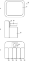
図2を参照して説明すると、表示装置30は、図2Aに示すように入力表示部31の一例であるタッチパネルを有する本体部38を備えている。そして、制御部32を構成するプロセッサ及びメモリは、本体部38に内蔵されている。また、図2Bに示すように、表示装置30は、入力表示部31を保持するホルダー36を備えている。そして、表示装置30は、ホルダー36によって患者が横たわるベッド、体外循環システム100の一部、又は呼吸補助システム200の一部に固定される。
Explaining with reference to FIG. 2, the
さらに、表示装置30には、図2Cに示すように複数の拡張カートリッジ39が取り付け可能である。拡張カートリッジ39を取り付け又は交換することによって、表示装置30が表示するデータの種類を追加又は変更できる。この点、表示可能なデータが限定されていると、表示装置30において、データを集約したグラフの描画を行うことができない。一方、表示装置30によれば、拡張カートリッジ39の組合せを変えることによって、様々なデータを組み合わせて検出及び表示できる。そのため、様々なデータを組み合わせて、医学的に新しい指標を得ることができる。さらに、拡張カートリッジ39には、センサーケーブル(不図示)を接続できる。これにより、体外循環システム100又は呼吸補助システム200が接続されていなくても、呼吸系データ及び血液系データを取得して、患者の状態を監視できる。
Furthermore, as shown in FIG. 2C, a plurality of
制御部32は、不図示のプロセッサを有している。一例として、制御部32のプロセッサは、CPU(Central Processing Unit)、又はMPU(Micro-Processing Unit)であり、メモリに記憶されたプログラムに基づいて、表示装置30の全体を制御すると共に、各種処理についても統括的に制御する。また、制御部32は、記憶部の一例として、コンピューター読み取り可能な非一時的記録媒体(不図示)を有している。そして、記憶部は、表示装置30の制御プログラムを記憶している。また、記憶部は、プロセッサが動作するためのシステムワークメモリであるRAM(Random Access Memory)、並びにプログラム及びシステムソフトウェアを格納するROM(Read Only Memory)、HDD(Hard Disc Drive)及びSSD(Solid State Drive)等の記憶装置を含む。
The
なお、制御部32は、CD(Compact Disc)、DVD(Digital Versatile Disc)、CF(Compact Flash)カード、及びUSB(Universal Serial Bus)メモリ等の可搬記録媒体、又はインターネット上のサーバー等の外部記憶媒体に記憶されたプログラムに従って表示装置30を制御することもできる。制御プログラムは、コンピューターとしての制御部32を、取得部33、表示制御部34、及び作成部35として機能させる。すなわち、制御部32は、コンピューターハードウエアとソフトウエアとの組み合わせによって実現される論理的装置として、取得部33、表示制御部34、及び作成部35を有している。
The
取得部33は、呼吸補助システム200から呼吸系データを取得し、体外循環システム100から血液系データを取得する。例えば、呼吸系データは、患者の肺の状態を示すデータを含み、患者の呼気から検出されるデータ及び当該データに基づいて算出又は推測されるデータ等である。また、血液系データは、患者の血液の状態を示すデータを含み、患者の血液から検出されるデータ及び当該データに基づいて算出又は推測されるデータ等である。さらに、呼吸系データは、呼気終末二酸化炭素分圧の経時的な変化を示すデータ、及び呼吸死腔量の少なくとも一方を含んでいてもよい。また、血液系データは、動脈血の二酸化炭素分圧及び静脈血の二酸化炭素分圧の少なくとも一方を含んでいてもよい。さらに、血液系データは、人工肺の酸素消費量の経時的な変化を示す人工肺酸素データと、人工肺の二酸化炭素生産量の経時的な変化を示す人工肺二酸化炭素データとを含んでいてもよい。また、呼吸系データは、生体肺の酸素消費量の経時的な変化を示す生体肺酸素データと、生体肺の二酸化炭素生産量の経時的な変化を示す生体肺二酸化炭素データとを含んでいてもよい。
The
代替的に、取得部33は、体外循環システム100及び呼吸補助システム200を構成しない外部検出装置又は他の医療用装置から、呼吸系データ及び血液系データの少なくとも一方を取得してもよい。なお、取得部33が取得して入力表示部31が表示する呼吸系データ及び血液系データは、上記のデータには限定されない。
Alternatively, the
また、血液系データは、動脈酸素分圧PaO2、静脈酸素分圧PvO2、動脈二酸化炭素分圧PaCO2、静脈二酸化炭素分圧PvCO2、酸素分圧PO2、二酸化炭素分圧PCO2、血液中の酸とアルカリのバランスを示すペーハーpH、カリウム濃度K+、ナトリウム濃度Na+、ラクテート濃度Lac、動脈血温度Ta、静脈血温度Tv、血液に占める赤血球の割合であるヘマトクリット値HCT、血液中に含まれるヘモグロビンの量である血色素量Hgb、酸素飽和度SO2、動脈酸素飽和度SaO2、静脈酸素飽和度SvO2、血液を体外において循環する流量である血液灌流量Q、経皮的動脈血酸素飽和度SPO2、人工肺へ流すスイープガスの流量であるスイープガス流量SWEEP GAS F、人工肺へ流すスイープガスの圧力であるスイープガス圧SWEEP GAS P IN、人工肺から流れて出るスイープガスの圧力であるスイープガス圧SWEEP GAS P OUT、人工肺スイープガス入口の圧力であるSWEEP GAS P INから人工肺スイープガス出口の圧力であるSWEEP GAS P OUTを減算して得られる値SWEEP GASΔP、スイープガス酸素濃度SWEEP GAS FIO2、血液の温度である温度Temp、送血圧である圧力Press、人工肺入口の圧力である入口圧P IN、人工肺出口の圧力である出口圧P OUT、人工肺入口圧から人工肺出口圧を減算して得られる値ΔP、pHを正常に戻すために増減が必要な酸の量であるベースエクセス値BE、血漿中のHCO3-濃度である重炭酸イオン濃度HCO3-、一分間で消費する酸素の量である酸素消費量VO2、一分間で運搬される酸素の量である酸素運搬量DO2、体表面積当たりの一分間で消費する酸素量である酸素消費量インデックスVO2i、体表面積当たりの一分間で運搬される酸素量である酸素運搬量インデックスDO2i、酸素運搬量に対する酸素消費量の割合である酸素摂取率O2ER、二酸化炭素生産量に対する酸素運搬量の割合であるRanucci比率DO2/VCO2、酸素消費量に対する二酸化炭素生産量の割合である呼吸商RQ、麻酔ガス摂取量VAA、及び安静時エネルギー消費量REEを含んでいてもよい。 The blood system data includes arterial oxygen partial pressure PaO2 , venous oxygen partial pressure PvO2 , arterial carbon dioxide partial pressure PaCO2 , venous carbon dioxide partial pressure PvCO2, oxygen partial pressure PO2 , carbon dioxide partial pressure PCO2 , pH indicating the acid-alkalinity balance in the blood, potassium concentration K+, sodium concentration Na+, lactate concentration Lac, arterial blood temperature Ta, venous blood temperature Tv, hematocrit value HCT which is the percentage of red blood cells in the blood, hemoglobin content Hgb which is the amount of hemoglobin in the blood, oxygen saturation SO2 , arterial oxygen saturation SaO2 , venous oxygen saturation SvO2 , blood perfusion rate Q which is the flow rate of blood circulating outside the body, percutaneous arterial blood oxygen saturation SPO2 , sweep gas flow rate SWEEP GAS F which is the flow rate of the sweep gas flowing to the oxygenator, and sweep gas pressure SWEEP GAS P which is the pressure of the sweep gas flowing to the oxygenator. IN, sweep gas pressure SWEEP GAS P OUT which is the pressure of the sweep gas flowing out of the oxygenator, SWEEP GAS ΔP which is the value obtained by subtracting SWEEP GAS P OUT which is the pressure at the oxygenator sweep gas outlet from SWEEP GAS P IN which is the pressure at the oxygenator sweep gas inlet, SWEEP GAS ΔP which is the sweep gas oxygen concentration SWEEP GAS FIO 2 , temperature Temp which is the blood temperature, pressure Press which is the delivery blood pressure, inlet pressure P IN which is the pressure at the oxygenator inlet, outlet pressure P OUT which is the pressure at the oxygenator outlet, ΔP which is the value obtained by subtracting the oxygenator outlet pressure from the oxygenator inlet pressure, base excess value BE which is the amount of acid that needs to be increased or decreased to return the pH to normal, bicarbonate ion concentration HCO 3 - which is the HCO 3 - concentration in plasma, oxygen consumption VO 2 which is the amount of oxygen consumed in one minute, oxygen delivery volume DO 2 which is the amount of oxygen delivered in one minute, oxygen consumption index VO 2 which is the amount of oxygen consumed per minute per body surface area i, the oxygen delivery index DO2i , which is the amount of oxygen delivered per body surface area per minute, the oxygen uptake rate O2ER , which is the ratio of oxygen consumption to oxygen delivery, the Ranucci ratio DO2 / VCO2 , which is the ratio of oxygen delivery to carbon dioxide production, the respiratory quotient RQ, which is the ratio of carbon dioxide production to oxygen consumption, the anesthetic gas intake VAA, and the resting energy expenditure REE.
さらに、血液系データは、人工肺又は患者の生体肺の状態を示すデータを含んでいてもよい。例えば、当該データは、生体肺酸素消費量V'O2 NL、生体肺二酸化炭素生産量V'CO2 NL、人工肺と生体肺の酸素消費量の合計である酸素消費量V'O2 TOTAL、人工肺と生体肺の二酸化炭素生産量の合計である二酸化炭素生産量V'CO2 TOTAL、生体肺及び人工肺の酸素消費量の合計に対する生体肺酸素消費量の割合である酸素消費量イメージV'O2 image、生体肺及び人工肺の二酸化炭素生産量の合計に対する生体肺二酸化炭素生産量の割合である二酸化炭素生産量イメージV'CO2 image、人工肺死腔量VD ML、生体肺死腔量VD NL、人工肺のPaO2とFiO2の比であるP/F ML、生体肺のPaO2とFiO2の比であるP/F NL、人工肺入口二酸化炭素濃度SWEEP GAS FICO2、人工肺出口二酸化炭素濃度SWEEP GAS FECO2、人工肺入口酸素濃度SWEEP GAS FIO2、人工肺出口酸素濃度SWEEP GAS FEO2、人工肺出口ガス温度TE、人工肺出口体温T、人工肺入口麻酔ガス濃度FIAA、及び人工肺出口麻酔ガス濃度FEAAを含んでいてもよい。 Additionally, the blood system data may include data indicative of the condition of the artificial lung or the patient's native lungs. For example, the data includes oxygen consumption V'O2NL of the living lung, carbon dioxide production V'CO2NL of the living lung, oxygen consumption V'O2TOTAL which is the sum of oxygen consumption of the artificial lung and the living lung, carbon dioxide production V'CO2TOTAL which is the sum of carbon dioxide production of the artificial lung and the living lung, oxygen consumption image V'O2image which is the ratio of oxygen consumption of the living lung to the sum of oxygen consumption of the living lung and the artificial lung, carbon dioxide production image V'CO2image which is the ratio of carbon dioxide production of the living lung to the sum of carbon dioxide production of the living lung and the artificial lung, dead space volume of the artificial lung VDML , dead space volume of the living lung VDNL, ratio of PaO2 to FiO2 of the artificial lung P/FML, ratio of PaO2 to FiO2 of the living lung P/FNL, carbon dioxide concentration at the inlet of the artificial lung SWEEP GAS FICO2 , carbon dioxide concentration at the outlet of the artificial lung SWEEP GAS FECO2 , oxygen concentration at the inlet of the artificial lung SWEEP GAS FICO2 , oxygen concentration at the oxygen outlet SWEEP GAS FEO 2 , oxygen outlet gas temperature TE, oxygen outlet body temperature T, oxygen inlet anesthetic gas concentration FIAA, and oxygen outlet anesthetic gas concentration FEAA.
また、呼吸系データは、人工肺酸素消費量V'O2 ML、人工肺二酸化炭素生産量V'CO2 ML、一回の吸気量である吸気量VI、一回の呼気量である呼気量VE、ガス交換がない無効な換気量である呼吸死腔量VDresp、ガス交換があり有効な換気量である肺胞換気量VA、混合呼気二酸化炭素濃度FECO2、一分間で生産した二酸化炭素の量である二酸化炭素生産量VCO2、呼気終末二酸化炭素分圧ETCO2、気道死腔量VDaw、肺胞気二酸化炭素濃度FACO2、一分間の呼吸数である呼吸数RR、気道にかかる内圧である気道内圧Paw、食道にかかる内圧である食道内圧Pes、気道内圧から食道内圧を引いた値である経肺圧PL、PaO2とFiO2の比であるP/F、肺の膨らみやすさを表す指標である肺コンプライアンスCL、呼気終末陽圧PEEP、デスフルレン摂取量DES、セボフルレン摂取量SEV、及びイソフルレン摂取量ISOを含んでいてもよい。 Respiratory system data includes oxygen consumption in the artificial lung V'O2 ML, carbon dioxide production in the artificial lung V'CO2 ML, inspiratory volume VI, which is the volume of air in one breath, expiratory volume VE, which is the volume of air in one breath, respiratory dead space volume VDresp, which is the ineffective ventilation volume without gas exchange, alveolar ventilation volume VA, which is the effective ventilation volume with gas exchange, mixed exhaled carbon dioxide concentration FECO2 , carbon dioxide production volume VCO2 , which is the amount of carbon dioxide produced in one minute, end-tidal carbon dioxide partial pressure ETCO2 , airway dead space volume VDaw, alveolar carbon dioxide concentration FACO2 , respiratory rate RR, which is the number of breaths per minute, airway pressure Paw, which is the internal pressure applied to the airway, esophageal pressure Pes, which is the internal pressure applied to the esophagus, transpulmonary pressure PL, which is the value obtained by subtracting esophageal pressure from airway pressure, and PaO2 and FiO These may include P/F, which is the ratio of P/F to 2 , lung compliance CL, which is an index representing the ease of lung expansion, positive end-expiratory pressure PEEP, desflurane intake DES, sevoflurane intake SEV, and isoflurane intake ISO.
表示制御部34は、取得部33が取得した呼吸系データと血液系データとが同時に表示されるように、入力表示部31を制御する。また、表示制御部34は、生体肺酸素データと人工肺酸素データとが並んで表示されるように、入力表示部31を制御してもよい。さらに、表示制御部34は、生体肺二酸化炭素データと人工肺二酸化炭素データとが並んで表示されるように、入力表示部31を制御してもよい。
The
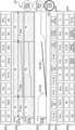
一例として図3に示すECMO用の判断画面では、呼吸系データを表示する呼吸系データ領域DA1と、血液系データを表示するその他の領域とが含まれており、入力表示部31によって同時に表示されている。その他の領域には、グラフィックデータ領域DA2、グラフデータ領域DA3、動脈血データ領域DA4、静脈血データ領域DA5、電解質データ領域DA6、ガス/圧力データ領域DA7、及び肺データ領域DA8が含まれている。なお、図3の各領域においては略号で示されているが、実際の画面では各領域に数値が表示されている。代替的に、表示制御部34は、略号で示されている部分を医療従事者がタッチ操作することによって、各略号に対応するデータの数値を画面に表示させてもよい。
As an example, the judgment screen for ECMO shown in FIG. 3 includes a respiratory system data area DA1 that displays respiratory system data and other areas that display blood system data, which are displayed simultaneously by the
グラフィックデータ領域DA2には、人工肺酸素データの一例である時系列毎の人工肺酸素消費量V'O2 MLと、生体肺酸素データの一例である時系列毎の生体肺酸素消費量V'O2 NLとを、それぞれの割合が面積によって表されるようにグラフィック化した酸素消費量画像が表示されている。これにより、入力表示部31は、生体肺酸素データと人工肺酸素データとを並べて表示している。また、グラフィックデータ領域DA2には、人工肺二酸化炭素データの一例である時系列毎の人工肺二酸化炭素生産量V'CO2 MLと、人工肺二酸化炭素データの一例である時系列毎の生体肺二酸化炭素生産量V'CO2 NLとを、それぞれの割合が面積によって表されるようにグラフィック化した二酸化炭素生産量画像が表示されている。これにより、入力表示部31は、生体肺二酸化炭素データと人工肺二酸化炭素データとを並べて表示している。なお、「NL」は生体肺を示す略号であり、「ML」は人工肺を示す略号である。 In the graphic data area DA2, an oxygen consumption image is displayed in which the ratio of the oxygen consumption V'O2ML of the oxygen consumption ...
グラフデータ領域DA3には、時系列毎の人工肺死腔量VD ML及び時系列毎の生体肺死腔量VD NLとが表示されている。なお、グラフィックデータ領域DA2及びグラフデータ領域DA3の横軸は日数(day)であるが、時間(hour)であってもよい。 Graph data area DA3 displays the artificial lung dead space volume VD ML for each time series and the biological lung dead space volume VD NL for each time series. Note that the horizontal axis of graphic data area DA2 and graph data area DA3 is days, but it may also be hours.
図3に示す判断画面は、患者からECMOを外すか否かを判断するためのデータを医療従事者に提供する。すなわち、判断画面では、生体肺のガス交換に関する血液系データと呼吸系データとを一画面に表示する。これにより、判断画面は、血液ガスの検出による血液系データの監視に加えて、患者の生体肺の状態を示す呼吸系データを監視する機能を持つ。そのため、医療従事者は、生体のガス交換状況の変化を連続してモニターできる。そして、医療従事者は、生体肺及び人工肺の変化を容易に監視できるので、安全な体外循環を実施できる。 The decision screen shown in Figure 3 provides medical personnel with data for deciding whether or not to remove ECMO from the patient. That is, the decision screen displays blood system data and respiratory system data related to gas exchange in the vital lungs on one screen. As a result, the decision screen has a function of monitoring respiratory system data that indicates the state of the patient's vital lungs, in addition to monitoring blood system data by detecting blood gases. Therefore, medical personnel can continuously monitor changes in the gas exchange status of the vital lung. And, because medical personnel can easily monitor changes in the vital lungs and the artificial lung, safe extracorporeal circulation can be performed.
通常人間は、組織を維持するために年齢、性別、及び体格に応じた酸素需要量を、自身が呼吸することにより酸素を取り込むと共に、二酸化炭素の排泄を行っている。この生体肺によるガス交換機能に、ウィルス性肺炎等によって重度な障害が生じることがある。この場合、生体肺機能を補助する人工呼吸器を使用する。肺炎がさらに悪化すると、人工呼吸器だけでは適切なガス交換が維持出来なくなる。そのため、ECMOを使用してガス交換を維持する。ECMOは、主に呼吸と循環の2つの補助を行うVA-ECMOと、呼吸補助のみを実施するVV-ECMOとが有る。そして、患者の状態に応じてVA-ECMOかVV-ECMOが選択される。ここで、ウィルス性肺炎のように、肺のみが重症化した症例においては、生体肺を休ませること(ラングレスト)を目的としたVV-ECMOが選択される。 Normally, humans breathe to take in oxygen and excrete carbon dioxide in order to maintain tissues, meeting the oxygen demand according to age, sex, and physical build. This gas exchange function of the vital lungs can be severely impaired by viral pneumonia, etc. In this case, an artificial ventilator is used to support the vital lung function. If the pneumonia worsens, the artificial ventilator alone will not be able to maintain proper gas exchange. Therefore, ECMO is used to maintain gas exchange. There are two types of ECMO: VA-ECMO, which mainly supports both breathing and circulation, and VV-ECMO, which only supports breathing. Either VA-ECMO or VV-ECMO is selected depending on the patient's condition. Here, in cases where only the lungs have become severely affected, such as viral pneumonia, VV-ECMO is selected with the aim of resting the vital lungs (run rest).
VV-ECMOでは、静脈脱血及び静脈送血が行われ、送血及び脱血の場所が必然的に近傍となる。これにより、酸素化した血液と酸素化していない血液が混ざるリサキュレーションが生じるため、人工肺によるガス交換効率が低下する。また、生体肺の肺胞を膨らませた状態を維持するため、生体肺によるガス交換も最低限維持される。したがって、VV-ECMOを実施するときのガス交換は、人工肺及び生体肺で行われることになる。そのため、患者にとって最適なガス交換状態を維持するためには、人工肺と生体肺の両方の状態を監視して管理することが必要になる。この点、判断画面では、血液系データと呼吸系データとを一画面に表示する。これにより、一つの表示装置30において両データを監視できるので、体外循環が必要な患者の管理が容易となる。
In VV-ECMO, venous blood withdrawal and return are performed, and the locations of blood return and withdrawal are inevitably close to each other. This causes recirculation, in which oxygenated blood mixes with non-oxygenated blood, reducing the efficiency of gas exchange by the artificial lung. In addition, in order to keep the alveoli of the vital lung inflated, gas exchange by the vital lung is also maintained to a minimum. Therefore, gas exchange when performing VV-ECMO is performed by the artificial lung and the vital lung. Therefore, in order to maintain an optimal gas exchange state for the patient, it is necessary to monitor and manage the state of both the artificial lung and the vital lung. In this regard, the judgment screen displays blood system data and respiratory system data on a single screen. This allows both data to be monitored on a
特に、判断画面では、ECMOによる処置を開始する開始タイミング、ECMOによる処置を終了する終了タイミング、及び患者の状態の変化タイミングを一画面において判断できる。具体的に、図3を参照して、開始タイミング、終了タイミング、及び変化タイミングについて説明する。なお、説明の便宜上、図3においては、グラフィックデータ領域DA2に、第1状態TR1、第2状態TR2、及び第3状態TR3を矢印付き直線で示している。 In particular, the judgment screen allows the start timing for starting ECMO treatment, the end timing for ending ECMO treatment, and the timing for a change in the patient's condition to be determined on a single screen. Specifically, the start timing, end timing, and change timing will be explained with reference to FIG. 3. For ease of explanation, the first state TR1, second state TR2, and third state TR3 are shown by straight lines with arrows in the graphic data area DA2 in FIG. 3.
患者の状態は、生体肺が悪化して酸素化が不足していく第1状態TR1から、人工肺による酸素化の補助が行われる第2状態TR2へと移行する。さらに、患者の状態は、第2状態TR2から、生体肺が回復して生体肺による酸素化に切り替える第3状態TR3へと移行する。第1状態TR1及び第3状態TR3では、人工呼吸器による補助が行われる。そして、第2状態TR2では、人工呼吸器に加えて、ECMOによる補助が行われる。そして、グラフィックデータ領域DA2においては、第1状態TR1と第2状態TR2との境界が変化タイミングであり且つ開始タイミングである。また、第2状態TR2と第3状態TR3との境界が変化タイミングであり且つ終了タイミングである。そのため、医療従事者は、判断画面を見ながら、ECMOによる処置の開始と終了を判断できる。 The patient's condition transitions from a first state TR1, in which the vital lungs deteriorate and oxygenation becomes insufficient, to a second state TR2, in which oxygenation is assisted by an artificial lung. Furthermore, the patient's condition transitions from the second state TR2 to a third state TR3, in which the vital lungs recover and oxygenation is switched to the vital lungs. In the first state TR1 and the third state TR3, assistance is provided by an artificial respirator. And in the second state TR2, assistance is provided by ECMO in addition to the artificial respirator. And in the graphic data area DA2, the boundary between the first state TR1 and the second state TR2 is the change timing and the start timing. And the boundary between the second state TR2 and the third state TR3 is the change timing and the end timing. Therefore, the medical staff can judge the start and end of treatment by ECMO while looking at the judgment screen.
例えば、表示装置30は、呼吸系データとして、呼気終末二酸化炭素分圧ETCO2の経時的な変化を示すグラフ、及び呼吸死腔量VDrespの少なくとも一方と、血液系データとして、動脈血の二酸化炭素分圧PaCO2及び静脈血の二酸化炭素分圧PvCO2の少なくとも一方とを同時に表示する。呼吸死腔量が分かることによって、CT撮影しなくとも肺炎又は炎症の程度、すなわち生体肺の状態を把握できる。これにより、呼吸系データと血液系データとを一画面に表示して、ECMOの開始タイミング又は終了タイミングを判断できる。また、医療従事者は、呼吸系データと血液系データとの相関を視覚的に把握できる。なお、血液系データも、数値だけではなく、例えばグラフ等によって経時的な変化を示してもよい。
For example, the
一方、血液系データを監視するモニターと、呼吸系データを監視するモニターとが別であると、医療従事者は、それぞれのモニターを監視することになる。この場合、医療従事者は、血液系データと呼吸系データとのそれぞれを総合的に考慮する必要がある。その上で、医療従事者は、ECMOの開始タイミング及び終了タイミングを判断し、体外循環が適切に行われている否かを判断する。そのため、血液系データと呼吸系データの比較が困難となる。また、血液系データと呼吸系データを連続してみることができず、医療従事者の経験と技術によって体外循環を管理することになる。 On the other hand, if there are separate monitors for monitoring blood system data and respiratory system data, medical personnel will have to monitor each monitor. In this case, medical personnel need to take into consideration both the blood system data and the respiratory system data comprehensively. After that, medical personnel decide when to start and end ECMO, and whether extracorporeal circulation is being performed appropriately. This makes it difficult to compare blood system data and respiratory system data. In addition, blood system data and respiratory system data cannot be viewed consecutively, and extracorporeal circulation will have to be managed depending on the medical personnel's experience and skills.
図3に示す判断画面には、ボタン領域BTが設けられている。そして、ボタン領域BTには、「ONLY Respiration」と表示されている呼吸系画面ボタンと、「Pressure Blood Gas」と表示されている血液系画面ボタンと、「ECMO Judgment」と表示されている判断画面ボタンとが表示されている。医療従事者が判断画面ボタンをタッチ操作すると、判断画面が表示される。また、医療従事者が呼吸系画面ボタンをタッチ操作すると、図4に示す呼吸系画面が表示される。 The judgment screen shown in FIG. 3 has a button area BT. In the button area BT, a respiratory system screen button displaying "ONLY Respiration," a blood system screen button displaying "Pressure Blood Gas," and a judgment screen button displaying "ECMO Judgment" are displayed. When the medical staff touches the judgment screen button, the judgment screen is displayed. When the medical staff touches the respiratory system screen button, the respiratory system screen shown in FIG. 4 is displayed.
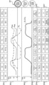
図4に示すように、呼吸系画面には、判断画面のグラフィックデータ領域DA2及びグラフデータ領域DA3に代えて、呼吸グラフ領域RA1及びRA2が設けられている。呼吸グラフ領域RA1には、気道内圧Paw、食道内圧Pes、及び経肺圧PLの経時的な変化を示すグラフが表示されている。また、呼吸グラフ領域RA2には、呼気終末二酸化炭素分圧ETCO2の経時的な変化を示すグラフが表示されている。 4, the respiratory system screen has respiration graph areas RA1 and RA2 instead of the graphic data area DA2 and graph data area DA3 of the judgment screen. The respiration graph area RA1 displays graphs showing the changes over time in the airway pressure Paw, the esophageal pressure Pes, and the transpulmonary pressure PL. The respiration graph area RA2 displays a graph showing the changes over time in the end-tidal carbon dioxide partial pressure ETCO2 .
また、医療従事者が血液系画面ボタンをタッチ操作すると、図5に示す血液系画面が表示される。血液系画面には、判断画面のグラフィックデータ領域DA2及びグラフデータ領域DA3に代えて、送血流量等の数値が表示される数値領域RA3が設けられている。なお、図5の数値領域RA3においては略号で示されているが、実際の画面では各領域に数値が表示されている。代替的に、表示制御部34は、略号で示されている部分を医療従事者がタッチ操作することによって、各略号に対応するデータの数値を画面に表示させてもよい。
When the medical staff touches the blood system screen button, the blood system screen shown in Figure 5 is displayed. Instead of the graphic data area DA2 and graph data area DA3 of the judgment screen, the blood system screen has a numerical area RA3 in which numerical values such as blood flow rate are displayed. Note that although abbreviations are used in the numerical area RA3 in Figure 5, numerical values are displayed in each area on the actual screen. Alternatively, the
図1に戻り、作成部35は、気道内圧Paw、食道内圧Pes、及び経肺圧PLの経時的な変化を示すグラフと、呼気終末二酸化炭素分圧の経時的な変化を示すグラフを作成する。また、作成部35は、酸素消費量画像と二酸化炭素生産量画像とを作成する。さらに、作成部35は、呼吸系データ又は血液系データに基づいて、経時的な変化を示すグラフ若しくは画像を作成してもよい。
Returning to FIG. 1, the
[画面表示処理]
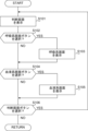
図6を参照して、画面表示処理について説明する。まず、表示制御部34は、判断画面(図3)を入力表示部31に表示させる(S101)。そして、医療従事者が呼吸系画面ボタンをタッチ操作すると(S102でYES)、表示制御部34は呼吸系画面(図4)を入力表示部31に表示させる(S103)。一方、医療従事者が呼吸系画面ボタンをタッチ操作せず(S102でNO)、血液系画面ボタンをタッチ操作すると(S104でYES)、表示制御部34は血液系画面(図5)を入力表示部31に表示させる(S105)。さらに、医療従事者が判断画面ボタンをタッチ操作すると(S106でYES)、表示制御部34は、判断画面を入力表示部31に表示させる(S101)。医療従事者が判断画面ボタンをタッチ操作しない場合(S106でNO)、画面の表示は変更されず、画面表示処理が終了する。
[Screen display processing]
The screen display process will be described with reference to FIG. 6. First, the
以上説明した表示装置30によれば、一つの画面において呼吸系データと血液系データ監視できるので、体外循環が必要な患者の管理が容易となる。また、各実施形態を参照して本発明について説明したが、本発明は上記実施形態に限定されるものではない。本発明に反しない範囲で変更された発明、及び本発明と均等な発明も本発明に含まれる。また、各実施形態及び各変形形態は、本発明に反しない範囲で適宜組み合わせることができる。
The
例えば、呼吸系データの表示はCOPD(Chronic Obstructive Pulmonary Disease)又はARDS(Acute Respiratory Distress Syndrome)の診療を行う際にも使用できる。 For example, the display of respiratory system data can be used when treating COPD (Chronic Obstructive Pulmonary Disease) or ARDS (Acute Respiratory Distress Syndrome).
30 :表示装置
31 :入力表示部(表示部)
34 :表示制御部
300:モニタシステム
30: Display device 31: Input display unit (display unit)
34: Display control unit 300: Monitor system
Claims (6)
前記患者の呼吸に関連する呼吸系データと、前記患者の血液に関連する血液系データとを表示する表示部と、
前記呼吸系データと前記血液系データとが同時に表示されるように、前記表示部を制御する表示制御部とを備え、
前記血液系データは、人工肺の二酸化炭素生産量の経時的な変化を示す人工肺二酸化炭素データを含み、
前記呼吸系データは、生体肺の二酸化炭素生産量の経時的な変化を示す生体肺二酸化炭素データを含み、
前記表示制御部は、前記生体肺二酸化炭素データと前記人工肺二酸化炭素データを、合計生産量に対するそれぞれの割合が面積によって表されるようにグラフィック化して、前記表示部に表示させる、表示装置。 1. A display device of a monitor system for monitoring a patient's condition, comprising:
a display unit for displaying respiratory system data related to the patient's breathing and blood system data related to the patient's blood;
a display control unit that controls the display unit so that the respiratory system data and the blood system data are simultaneously displayed ;
The blood system data includes oxygenator carbon dioxide data showing a change in the amount of carbon dioxide produced by the oxygenator over time;
The respiratory system data includes living body lung carbon dioxide data indicating a change in carbon dioxide production rate of the living body lungs over time,
The display control unit graphically converts the living lung carbon dioxide data and the artificial lung carbon dioxide data into data in such a way that the proportion of each data to a total production amount is represented by an area, and displays the data on the display unit .
前記血液系データは、前記患者の血液の状態を示すデータを含む、請求項1に記載の表示装置。 the respiratory system data includes data indicative of a lung condition of the patient;
The display device according to claim 1 , wherein the blood system data includes data indicating a blood condition of the patient.
前記患者の呼吸に関連する呼吸系データと、前記患者の血液に関連する血液系データとを表示する表示部と、
前記呼吸系データと前記血液系データとが同時に表示されるように、前記表示部を制御する表示制御部とを備え、
前記血液系データは、人工肺の酸素消費量の経時的な変化を示す人工肺酸素データを含み、
前記呼吸系データは、生体肺の酸素消費量の経時的な変化を示す生体肺酸素データを含み、
前記表示制御部は、前記生体肺酸素データと前記人工肺酸素データとを、合計消費量に対するそれぞれの割合が面積によって表されるようにグラフィック化して、前記表示部に表示させる、表示装置。 1. A display device of a monitor system for monitoring a patient's condition, comprising:
a display unit for displaying respiratory system data related to the patient's breathing and blood system data related to the patient's blood;
a display control unit that controls the display unit so that the respiratory system data and the blood system data are simultaneously displayed;
The blood system data includes oxygen data indicating a change in oxygen consumption of an artificial lung over time;
The respiratory system data includes living body lung oxygen data indicating a change in oxygen consumption of the living body lungs over time,
The display control unit graphically displays the biological pulmonary oxygen data and the artificial pulmonary oxygen data on the display unit so that the ratio of each data to a total consumption is represented by an area .
Priority Applications (1)
| Application Number | Priority Date | Filing Date | Title |
|---|---|---|---|
| JP2021143690A JP7689727B2 (en) | 2021-09-03 | 2021-09-03 | Display device for monitor system |
Applications Claiming Priority (1)
| Application Number | Priority Date | Filing Date | Title |
|---|---|---|---|
| JP2021143690A JP7689727B2 (en) | 2021-09-03 | 2021-09-03 | Display device for monitor system |
Publications (2)
| Publication Number | Publication Date |
|---|---|
| JP2023037132A JP2023037132A (en) | 2023-03-15 |
| JP7689727B2 true JP7689727B2 (en) | 2025-06-09 |
Family
ID=85509205
Family Applications (1)
| Application Number | Title | Priority Date | Filing Date |
|---|---|---|---|
| JP2021143690A Active JP7689727B2 (en) | 2021-09-03 | 2021-09-03 | Display device for monitor system |
Country Status (1)
| Country | Link |
|---|---|
| JP (1) | JP7689727B2 (en) |
Citations (5)
| Publication number | Priority date | Publication date | Assignee | Title |
|---|---|---|---|---|
| US20150034082A1 (en) | 2013-08-05 | 2015-02-05 | Covidien Lp | Oxygenation-ventilation methods and systems |
| JP2017518106A (en) | 2014-06-05 | 2017-07-06 | ハミルトン メディカル アーゲー | Ventilation system for mechanical ventilation and extracorporeal blood gas exchange |
| US20200121199A1 (en) | 2018-10-23 | 2020-04-23 | Zoll Medical Corporation | Data playback interface for a medical device |
| WO2021078966A1 (en) | 2019-10-24 | 2021-04-29 | Xenios Ag | Expert module for artificial respiration and ecls |
| JP2021512660A (en) | 2018-02-07 | 2021-05-20 | ユーロセッツ エス.アール.エル. | External support for cardiovascular device A device for continuously monitoring blood properties in a circulatory system |
-
2021
- 2021-09-03 JP JP2021143690A patent/JP7689727B2/en active Active
Patent Citations (5)
| Publication number | Priority date | Publication date | Assignee | Title |
|---|---|---|---|---|
| US20150034082A1 (en) | 2013-08-05 | 2015-02-05 | Covidien Lp | Oxygenation-ventilation methods and systems |
| JP2017518106A (en) | 2014-06-05 | 2017-07-06 | ハミルトン メディカル アーゲー | Ventilation system for mechanical ventilation and extracorporeal blood gas exchange |
| JP2021512660A (en) | 2018-02-07 | 2021-05-20 | ユーロセッツ エス.アール.エル. | External support for cardiovascular device A device for continuously monitoring blood properties in a circulatory system |
| US20200121199A1 (en) | 2018-10-23 | 2020-04-23 | Zoll Medical Corporation | Data playback interface for a medical device |
| WO2021078966A1 (en) | 2019-10-24 | 2021-04-29 | Xenios Ag | Expert module for artificial respiration and ecls |
Also Published As
| Publication number | Publication date |
|---|---|
| JP2023037132A (en) | 2023-03-15 |
Similar Documents
| Publication | Publication Date | Title |
|---|---|---|
| Unzueta et al. | Alveolar recruitment improves ventilation during thoracic surgery: a randomized controlled trial | |
| CN106659831B (en) | Ventilation system for mechanical ventilation and extracorporeal blood-gas exchange | |
| WO2011021978A1 (en) | Coordinated control of ventilator and lung assist device | |
| US20210353892A1 (en) | System for supplying gases for ventilation and oxygenation with feed of inhalable substances | |
| CN114042216A (en) | Anesthesia machine and system | |
| Zanella et al. | Extracorporeal carbon dioxide removal through ventilation of acidified dialysate: an experimental study | |
| US20230173208A1 (en) | Flow therapy system and method | |
| WO2021071366A1 (en) | Flow therapy system and method | |
| CN114586105A (en) | Expert module and ECLS for artificial respiration | |
| Palmer | Ventilatory support of the critically ill foal | |
| JP7689727B2 (en) | Display device for monitor system | |
| JP7553950B2 (en) | Auxiliary circulatory control device, auxiliary circulatory system | |
| TWI858297B (en) | Monitoring device and auxiliary circulation device | |
| Maillie et al. | Dioxide Monitoring | |
| Thornton et al. | Ventilator Management in Patients on Veno-Venous Extracorporeal Membrane Oxygenation at a Small ECMO Center | |
| Mastoras et al. | Just the facts: initiating mechanical ventilation in the emergency department | |
| US20070255159A1 (en) | Independent control and regulation of blood gas, pulmonary resistance, and sedation using an intravascular membrane catheter | |
| Baker | Artificial ventilation in the intensive care unit: an overview | |
| Abdelazim et al. | Effect of Oxygen Therapy by Venturi Mask Versus Noninvasive Ventilation and Its Outcome in Acute Exacerbation of Chronic Obstructive Pulmonary Disease Patients | |
| Wang et al. | Clinical application of a connection device consisting of a bag valve mask and nebulizer in first aid: Two case reports | |
| WO2025132588A1 (en) | System and method for determining oxygen consumption and carbon dioxide production and energy expenditure of a patient | |
| CN119317414A (en) | Patient temperature control during gas exchange therapy | |
| Dávila | Beyond Respiratory Failure: A Panoptic Perspective of Ventilation and Ventilatory Failure | |
| Pierce | Protocols for practice: Traditional and nontraditional modes of mechanical ventilation | |
| Pruitt | Latest advances in respiratory care |
Legal Events
| Date | Code | Title | Description |
|---|---|---|---|
| A621 | Written request for application examination |
Free format text: JAPANESE INTERMEDIATE CODE: A621 Effective date: 20240619 |
|
| A977 | Report on retrieval |
Free format text: JAPANESE INTERMEDIATE CODE: A971007 Effective date: 20250226 |
|
| A131 | Notification of reasons for refusal |
Free format text: JAPANESE INTERMEDIATE CODE: A131 Effective date: 20250311 |
|
| A521 | Request for written amendment filed |
Free format text: JAPANESE INTERMEDIATE CODE: A523 Effective date: 20250430 |
|
| TRDD | Decision of grant or rejection written | ||
| A01 | Written decision to grant a patent or to grant a registration (utility model) |
Free format text: JAPANESE INTERMEDIATE CODE: A01 Effective date: 20250520 |
|
| A61 | First payment of annual fees (during grant procedure) |
Free format text: JAPANESE INTERMEDIATE CODE: A61 Effective date: 20250521 |
|
| R150 | Certificate of patent or registration of utility model |
Ref document number: 7689727 Country of ref document: JP Free format text: JAPANESE INTERMEDIATE CODE: R150 |