JP7688024B2 - Helical Nerve Cuffs and Related Implantable Devices - Google Patents
Helical Nerve Cuffs and Related Implantable Devices Download PDFInfo
- Publication number
- JP7688024B2 JP7688024B2 JP2022523041A JP2022523041A JP7688024B2 JP 7688024 B2 JP7688024 B2 JP 7688024B2 JP 2022523041 A JP2022523041 A JP 2022523041A JP 2022523041 A JP2022523041 A JP 2022523041A JP 7688024 B2 JP7688024 B2 JP 7688024B2
- Authority
- JP
- Japan
- Prior art keywords
- helical
- nerve cuff
- implantable device
- nerve
- cuff
- Prior art date
- Legal status (The legal status is an assumption and is not a legal conclusion. Google has not performed a legal analysis and makes no representation as to the accuracy of the status listed.)
- Active
Links
Images


Classifications
-
- A—HUMAN NECESSITIES
- A61—MEDICAL OR VETERINARY SCIENCE; HYGIENE
- A61N—ELECTROTHERAPY; MAGNETOTHERAPY; RADIATION THERAPY; ULTRASOUND THERAPY
- A61N1/00—Electrotherapy; Circuits therefor
- A61N1/02—Details
- A61N1/04—Electrodes
- A61N1/05—Electrodes for implantation or insertion into the body, e.g. heart electrode
- A61N1/0551—Spinal or peripheral nerve electrodes
- A61N1/0556—Cuff electrodes
-
- A—HUMAN NECESSITIES
- A61—MEDICAL OR VETERINARY SCIENCE; HYGIENE
- A61N—ELECTROTHERAPY; MAGNETOTHERAPY; RADIATION THERAPY; ULTRASOUND THERAPY
- A61N1/00—Electrotherapy; Circuits therefor
- A61N1/18—Applying electric currents by contact electrodes
- A61N1/32—Applying electric currents by contact electrodes alternating or intermittent currents
- A61N1/36—Applying electric currents by contact electrodes alternating or intermittent currents for stimulation
- A61N1/36007—Applying electric currents by contact electrodes alternating or intermittent currents for stimulation of urogenital or gastrointestinal organs, e.g. for incontinence control
-
- A—HUMAN NECESSITIES
- A61—MEDICAL OR VETERINARY SCIENCE; HYGIENE
- A61N—ELECTROTHERAPY; MAGNETOTHERAPY; RADIATION THERAPY; ULTRASOUND THERAPY
- A61N1/00—Electrotherapy; Circuits therefor
- A61N1/18—Applying electric currents by contact electrodes
- A61N1/32—Applying electric currents by contact electrodes alternating or intermittent currents
- A61N1/36—Applying electric currents by contact electrodes alternating or intermittent currents for stimulation
- A61N1/3605—Implantable neurostimulators for stimulating central or peripheral nerve system
- A61N1/36053—Implantable neurostimulators for stimulating central or peripheral nerve system adapted for vagal stimulation
-
- A—HUMAN NECESSITIES
- A61—MEDICAL OR VETERINARY SCIENCE; HYGIENE
- A61N—ELECTROTHERAPY; MAGNETOTHERAPY; RADIATION THERAPY; ULTRASOUND THERAPY
- A61N1/00—Electrotherapy; Circuits therefor
- A61N1/18—Applying electric currents by contact electrodes
- A61N1/32—Applying electric currents by contact electrodes alternating or intermittent currents
- A61N1/36—Applying electric currents by contact electrodes alternating or intermittent currents for stimulation
- A61N1/3605—Implantable neurostimulators for stimulating central or peripheral nerve system
- A61N1/36128—Control systems
- A61N1/36135—Control systems using physiological parameters
-
- A—HUMAN NECESSITIES
- A61—MEDICAL OR VETERINARY SCIENCE; HYGIENE
- A61N—ELECTROTHERAPY; MAGNETOTHERAPY; RADIATION THERAPY; ULTRASOUND THERAPY
- A61N1/00—Electrotherapy; Circuits therefor
- A61N1/18—Applying electric currents by contact electrodes
- A61N1/32—Applying electric currents by contact electrodes alternating or intermittent currents
- A61N1/36—Applying electric currents by contact electrodes alternating or intermittent currents for stimulation
- A61N1/372—Arrangements in connection with the implantation of stimulators
- A61N1/37211—Means for communicating with stimulators
- A61N1/37217—Means for communicating with stimulators characterised by the communication link, e.g. acoustic or tactile
-
- A—HUMAN NECESSITIES
- A61—MEDICAL OR VETERINARY SCIENCE; HYGIENE
- A61N—ELECTROTHERAPY; MAGNETOTHERAPY; RADIATION THERAPY; ULTRASOUND THERAPY
- A61N1/00—Electrotherapy; Circuits therefor
- A61N1/18—Applying electric currents by contact electrodes
- A61N1/32—Applying electric currents by contact electrodes alternating or intermittent currents
- A61N1/36—Applying electric currents by contact electrodes alternating or intermittent currents for stimulation
- A61N1/372—Arrangements in connection with the implantation of stimulators
- A61N1/37211—Means for communicating with stimulators
- A61N1/37252—Details of algorithms or data aspects of communication system, e.g. handshaking, transmitting specific data or segmenting data
-
- A—HUMAN NECESSITIES
- A61—MEDICAL OR VETERINARY SCIENCE; HYGIENE
- A61N—ELECTROTHERAPY; MAGNETOTHERAPY; RADIATION THERAPY; ULTRASOUND THERAPY
- A61N1/00—Electrotherapy; Circuits therefor
- A61N1/18—Applying electric currents by contact electrodes
- A61N1/32—Applying electric currents by contact electrodes alternating or intermittent currents
- A61N1/36—Applying electric currents by contact electrodes alternating or intermittent currents for stimulation
- A61N1/372—Arrangements in connection with the implantation of stimulators
- A61N1/375—Constructional arrangements, e.g. casings
- A61N1/37518—Anchoring of the implants, e.g. fixation
-
- A—HUMAN NECESSITIES
- A61—MEDICAL OR VETERINARY SCIENCE; HYGIENE
- A61N—ELECTROTHERAPY; MAGNETOTHERAPY; RADIATION THERAPY; ULTRASOUND THERAPY
- A61N1/00—Electrotherapy; Circuits therefor
- A61N1/18—Applying electric currents by contact electrodes
- A61N1/32—Applying electric currents by contact electrodes alternating or intermittent currents
- A61N1/36—Applying electric currents by contact electrodes alternating or intermittent currents for stimulation
- A61N1/372—Arrangements in connection with the implantation of stimulators
- A61N1/375—Constructional arrangements, e.g. casings
- A61N1/3752—Details of casing-lead connections
- A61N1/3754—Feedthroughs
-
- A—HUMAN NECESSITIES
- A61—MEDICAL OR VETERINARY SCIENCE; HYGIENE
- A61N—ELECTROTHERAPY; MAGNETOTHERAPY; RADIATION THERAPY; ULTRASOUND THERAPY
- A61N1/00—Electrotherapy; Circuits therefor
- A61N1/18—Applying electric currents by contact electrodes
- A61N1/32—Applying electric currents by contact electrodes alternating or intermittent currents
- A61N1/36—Applying electric currents by contact electrodes alternating or intermittent currents for stimulation
- A61N1/372—Arrangements in connection with the implantation of stimulators
- A61N1/375—Constructional arrangements, e.g. casings
- A61N1/3758—Packaging of the components within the casing
-
- A—HUMAN NECESSITIES
- A61—MEDICAL OR VETERINARY SCIENCE; HYGIENE
- A61N—ELECTROTHERAPY; MAGNETOTHERAPY; RADIATION THERAPY; ULTRASOUND THERAPY
- A61N1/00—Electrotherapy; Circuits therefor
- A61N1/18—Applying electric currents by contact electrodes
- A61N1/32—Applying electric currents by contact electrodes alternating or intermittent currents
- A61N1/36—Applying electric currents by contact electrodes alternating or intermittent currents for stimulation
- A61N1/372—Arrangements in connection with the implantation of stimulators
- A61N1/378—Electrical supply
- A61N1/3787—Electrical supply from an external energy source
Landscapes
- Health & Medical Sciences (AREA)
- Life Sciences & Earth Sciences (AREA)
- Engineering & Computer Science (AREA)
- Biomedical Technology (AREA)
- Nuclear Medicine, Radiotherapy & Molecular Imaging (AREA)
- Radiology & Medical Imaging (AREA)
- Animal Behavior & Ethology (AREA)
- General Health & Medical Sciences (AREA)
- Public Health (AREA)
- Veterinary Medicine (AREA)
- Neurosurgery (AREA)
- Neurology (AREA)
- Orthopedic Medicine & Surgery (AREA)
- Cardiology (AREA)
- Heart & Thoracic Surgery (AREA)
- Acoustics & Sound (AREA)
- Physics & Mathematics (AREA)
- Gastroenterology & Hepatology (AREA)
- Biophysics (AREA)
- Physiology (AREA)
- Electrotherapy Devices (AREA)
- Measurement And Recording Of Electrical Phenomena And Electrical Characteristics Of The Living Body (AREA)
- Prostheses (AREA)
Description
[関連出願の相互参照]
本出願は、全ての目的のために参照により本明細書に組み込まれる、2019年10月17日に出願された米国仮出願第62/916,709号に対する優先権の利益を主張する。
CROSS-REFERENCE TO RELATED APPLICATIONS
This application claims the benefit of priority to U.S. Provisional Application No. 62/916,709, filed October 17, 2019, which is incorporated by reference herein for all purposes.
[技術分野]
ヘリカル(らせん状)神経カフと、ヘリカル神経カフおよび無線通信システムを備える埋め込み型(インプランタブル)デバイスとが、本明細書に記載される。また、ヘリカル神経カフおよびインプランタブルデバイスを埋め込む方法、ならびにヘリカル神経カフおよびインプランタブルデバイスを作製する方法も記載される。
[Technical field]
Described herein are helical (spiral) nerve cuffs and implantable devices that include helical nerve cuffs and wireless communication systems. Also described are methods of implanting and making the helical nerve cuffs and implantable devices.
個体の末梢神経系は、生命維持に必要な器官の活動や生理的恒常性を厳密に制御して働いている。神経を介して伝達される電気パルス(すなわち、活動電位)は、脈拍数、炎症、および膀胱または腸の制御などの様々な生理学的機能を変化させることができる。ある種の医学的状態は、これらの神経信号がターゲット器官に過剰刺激または過少刺激のいずれかを行うことによって身体を適切に制御できない場合に発生し得る。 The peripheral nervous system of an individual acts to tightly control the activity of vital organs and physiological homeostasis. Electrical impulses (i.e., action potentials) transmitted through nerves can alter various physiological functions such as pulse rate, inflammation, and bladder or bowel control. Certain medical conditions can occur when these nerve signals fail to adequately control the body by either overstimulating or understimulating target organs.
末梢神経系の電気信号を制御することにより、異常な生理的活動を治療するための侵襲的方法が開発されている。そのような方法は、電極の先端がターゲット神経に接触する状態で、患者の体内に電極を埋め込むことを含むことができる。これらの電極は一般に、外部装置に取り付けられる長いリード線を有し、これにより、患者は、電極の感染やまたは変位の実質的な危険にさらされる。さらに、多くの方法は非常に侵襲的であるため、特定の治療は臨床現場に限定され、在宅治療として使用することはできない。完全な埋込み型デバイスはより侵襲性の低い治療のために開発されてきたが、このようなデバイスは体の多くの位置に配置するには大きすぎる。したがって、埋め込まれたデバイスは、位置が変わるまたは破壊され得る長いリードの使用を必要とする。このような埋め込まれたデバイスはまた、迷走神経のような上流神経を刺激するために埋め込まれ、これは、ターゲット外の電気刺激による大きな副作用をもたらす。 Invasive methods have been developed to treat abnormal physiological activity by controlling electrical signals in the peripheral nervous system. Such methods can include implanting electrodes in the patient's body with the tip of the electrode in contact with the target nerve. These electrodes generally have long leads that are attached to an external device, which exposes the patient to substantial risks of infection or displacement of the electrode. Furthermore, many methods are so invasive that certain treatments are limited to clinical settings and cannot be used as home treatments. Fully implantable devices have been developed for less invasive treatments, but such devices are too large to be placed in many locations on the body. Thus, implanted devices require the use of long leads that can become dislocated or destroyed. Such implanted devices are also implanted to stimulate upstream nerves such as the vagus nerve, which results in significant side effects from off-target electrical stimulation.
これまで開発された神経カフは、より大きく、または容易に末梢神経に到達できる。しかしながら、そのような神経カフは、特定の神経に適切ではないか、または容易に埋め込み可能ではない場合がある。 Previously developed nerve cuffs have been larger or more easily adapted to reach peripheral nerves. However, such cuffs may not be suitable for certain nerves or may not be easily implantable.
ヘリカル神経カフ、およびヘリカル神経カフと無線通信システムを備える本体とを備えるインプランタブルデバイス、が本明細書に記載される。本体は、ヘリカル神経カフの外側表面に取り付けることができる。また、ヘリカル神経カフおよびインプランタブルデバイスを埋め込む方法、ならびにヘリカル神経カフおよびインプランタブルデバイスを作製する方法も記載される。 Described herein are helical nerve cuffs and implantable devices that include a helical nerve cuff and a body that includes a wireless communication system. The body can be attached to an outer surface of the helical nerve cuff. Also described are methods of implanting the helical nerve cuffs and implantable devices, as well as methods of making the helical nerve cuffs and implantable devices.
インプランタブルデバイスは、無線通信システムを含む本体と、神経によって伝達される電気生理学的信号を検出するか、または神経に電気パルスを放出するように構成された無線通信システムと電気的に通信する2つ以上の電極と、2つ以上の電極のうちの少なくとも1つを備えるヘリカル神経カフであって、本体はヘリカル神経カフ上にあり、ヘリカル神経カフは神経を有する線維組織の周りを少なくとも部分的に巻き、2つ以上の電極のうちの少なくとも1つを神経と電気的に通信するように配置する、ように構成される、ヘリカル神経カフと、を備えてもよい。 The implantable device may include a body including a wireless communication system, two or more electrodes in electrical communication with the wireless communication system configured to detect electrophysiological signals transmitted by the nerve or to emit electrical pulses to the nerve, and a helical nerve cuff comprising at least one of the two or more electrodes, the body being over the helical nerve cuff configured to at least partially wrap around the fibrous tissue having the nerve and position at least one of the two or more electrodes in electrical communication with the nerve.
いくつかの実施形態では、無線通信システムが超音波トランスデューサを備える。いくつかの実施形態では、超音波トランスデューサが最長寸法において長さが約5mm以下である。いくつかの実施形態では、無線通信システムが2つ以上の超音波トランスデューサを備える。 In some embodiments, the wireless communication system includes an ultrasonic transducer. In some embodiments, the ultrasonic transducer is about 5 mm or less in length in its longest dimension. In some embodiments, the wireless communication system includes two or more ultrasonic transducers.
いくつかの実施形態では、無線通信システムが無線周波数アンテナを備える。 In some embodiments, the wireless communication system includes a radio frequency antenna.
いくつかの実施形態では、無線通信システムが超音波または無線周波(radiofrequency)を受信し、超音波または無線周波からのエネルギーを、デバイスに電力を供給する電気エネルギーに変換するように構成される。 In some embodiments, the wireless communication system is configured to receive ultrasound or radio frequency and convert energy from the ultrasound or radio frequency into electrical energy that powers the device.
いくつかの実施形態では、ヘリカル神経カフは、少なくとも1回転、神経の周りを巻くように構成される。いくつかの実施形態では、ヘリカル神経カフが約1.3~約1.7回転、神経の周りを巻くように構成される。 In some embodiments, the helical nerve cuff is configured to wrap around the nerve at least one turn. In some embodiments, the helical nerve cuff is configured to wrap around the nerve about 1.3 to about 1.7 turns.
いくつかの実施形態では、ヘリカル神経カフは、ヘリカル神経カフの内側表面、第1の縁部、および第2の縁部を定義する幅を有し、ヘリカル神経カフが弛緩位置にあるとき、第1の縁部の少なくとも一部が第2の縁部の少なくとも一部に接触する。 In some embodiments, the helical nerve cuff has a width that defines an inner surface of the helical nerve cuff, a first edge, and a second edge, and at least a portion of the first edge contacts at least a portion of the second edge when the helical nerve cuff is in a relaxed position.
いくつかの実施形態では、ヘリカル神経カフは、ヘリカル神経カフの内側表面、第1の縁部、および第2の縁部を定義する幅を有し、ヘリカル神経カフが弛緩位置にあるとき、第1の縁部は第2の縁部に接触しない。 In some embodiments, the helical nerve cuff has a width that defines an inner surface of the helical nerve cuff, a first edge, and a second edge, and when the helical nerve cuff is in a relaxed position, the first edge does not contact the second edge.
いくつかの実施形態では、2つ以上の電極のうちの少なくとも1つはヘリカル神経カフの長さに沿って配置される。いくつかの実施形態では、ヘリカル神経カフの長さに沿って配置された2つ以上の電極のうちの少なくとも1つはヘリカル神経カフの内側表面に配置される。 In some embodiments, at least one of the two or more electrodes is positioned along the length of the helical nerve cuff. In some embodiments, at least one of the two or more electrodes positioned along the length of the helical nerve cuff is positioned on the inner surface of the helical nerve cuff.
ヘリカル神経カフの電極の少なくとも1つは、1つ以上の蛇行セグメントを含むことができる。 At least one of the electrodes of the helical nerve cuff can include one or more serpentine segments.
いくつかの実施形態では、ヘリカル神経カフが可撓性を有し、(a)ヘリカル神経カフを少なくとも部分的に巻き戻すことによって屈曲位置に、および(b)弛緩位置に構成可能である。 In some embodiments, the helical nerve cuff is flexible and configurable into (a) a flexed position by at least partially unwinding the helical nerve cuff, and (b) a relaxed position.
いくつかの実施形態では、インプランタブルデバイスは、ヘリカル神経カフまたは身体に取り付けられた1つ以上のハンドル部をさらに備える。いくつかの実施形態では、ハンドル部はループを含む。いくつかの実施形態では、ハンドル部はフィラメントを含む。いくつかの実施形態では、ハンドル部がヘリカル神経カフの端部に近位の位置で神経カフに取り付けられる。いくつかの実施形態では、インプランタブルデバイスは、ヘリカル神経カフの第2の端部に近位の位置でヘリカル神経カフに取り付けられた第2のハンドル部をさらに備える。いくつかの実施形態では、第1のハンドル部が第2のハンドルに取り付けられる。いくつかの実施形態では、デバイスがヘリカル神経カフの長さに沿った中間位置に取り付けられた追加のハンドル部分をさらに備える。 In some embodiments, the implantable device further comprises one or more handle portions attached to the helical nerve cuff or the body. In some embodiments, the handle portion comprises a loop. In some embodiments, the handle portion comprises a filament. In some embodiments, the handle portion is attached to the nerve cuff at a location proximal to an end of the helical nerve cuff. In some embodiments, the implantable device further comprises a second handle portion attached to the helical nerve cuff at a location proximal to a second end of the helical nerve cuff. In some embodiments, the first handle portion is attached to the second handle portion. In some embodiments, the device further comprises an additional handle portion attached to an intermediate location along the length of the helical nerve cuff.
インプランタブルデバイスは、本体およびヘリカル神経カフを受け入れ、それによって本体をヘリカル神経カフに取り付けるように構成されたマウントを含むことができる。代替的に、本体はヘリカル神経カフの外側表面などのヘリカル神経カフに直接取り付けられるか、または本体はヘリカル神経カフの端部に取り付けられる。いくつかの実施形態では、本体がヘリカル神経カフの中間部分に取り付けられる。いくつかの実施形態では、本体がヘリカル神経カフに取り付けられるアタッチメント端部と、アタッチメント端部から延在する延長端部とを備える。 The implantable device can include a mount configured to receive the body and the helical nerve cuff, thereby attaching the body to the helical nerve cuff. Alternatively, the body is attached directly to the helical nerve cuff, such as to an outer surface of the helical nerve cuff, or the body is attached to an end of the helical nerve cuff. In some embodiments, the body is attached to an intermediate portion of the helical nerve cuff. In some embodiments, the body comprises an attachment end that is attached to the helical nerve cuff and an extension end that extends from the attachment end.
いくつかの実施形態では、ヘリカル神経カフが右巻きらせん部を含む。いくつかの実施形態では、ヘリカル神経カフが左巻きらせん部を含む。いくつかの実施形態では、ヘリカル神経カフが左巻きらせん部に接合された右巻きらせん部を含む。いくつかの実施形態では、本体が右巻きらせん部が左巻きらせん部に接合される近位の位置でヘリカル神経カフに取り付けられる。いくつかの実施態様において、右巻きらせん部は、直線状の接合部分を介して左巻きらせん部に接合される。 In some embodiments, the helical nerve cuff comprises a right-handed helix. In some embodiments, the helical nerve cuff comprises a left-handed helix. In some embodiments, the helical nerve cuff comprises a right-handed helix joined to a left-handed helix. In some embodiments, the body is attached to the helical nerve cuff at a location proximal to where the right-handed helix is joined to the left-handed helix. In some embodiments, the right-handed helix is joined to the left-handed helix via a straight interface.
いくつかの実施形態では、ヘリカル神経カフが神経に電気パルスを放出するように構成された1つ以上の電極を備える。いくつかの実施形態では、ヘリカル神経カフが神経によって伝達される電気生理学的信号を検出するように構成された1つ以上の電極を備える。いくつかの実施形態では、ヘリカル神経カフが神経によって伝達される電気生理学的信号を検出するように構成された2つ以上の電極を備える。 In some embodiments, the helical nerve cuff comprises one or more electrodes configured to emit electrical pulses to the nerve. In some embodiments, the helical nerve cuff comprises one or more electrodes configured to detect electrophysiological signals transmitted by the nerve. In some embodiments, the helical nerve cuff comprises two or more electrodes configured to detect electrophysiological signals transmitted by the nerve.
いくつかの実施形態では、神経はヒトの脾神経である。いくつかの実施形態では、神経はヒトの内臓神経である。 In some embodiments, the nerve is a human splenic nerve. In some embodiments, the nerve is a human splanchnic nerve.
いくつかの実施形態では、本体はハウジングを含む。いくつかの実施形態では、ハウジングが2つ以上の電極のうちの1つとして構成される。いくつかの実施態様において、ハウジングは音響窓を含む。いくつかの実施形態では、ハウジングが音響伝導性材料を含む。 In some embodiments, the body includes a housing. In some embodiments, the housing is configured as one of two or more electrodes. In some implementations, the housing includes an acoustic window. In some embodiments, the housing includes an acoustically conductive material.
いくつかの実施形態では、本体が無線通信システムおよび2つ以上の電極に電気的に接続された集積回路を含む。いくつかの実施形態では、集積回路がキャパシタを含むエネルギー蓄積回路を含む。 In some embodiments, the body includes an integrated circuit electrically connected to the wireless communication system and the two or more electrodes. In some embodiments, the integrated circuit includes an energy storage circuit including a capacitor.
いくつかの実施形態では、本体が最長寸法で約8mm以下の長さである。 In some embodiments, the body is about 8 mm or less in length along its longest dimension.
ある実施形態では、無線通信システムがデータを送信するように構成される。いくつかの実施形態では、無線通信システムがデータを符号化する超音波後方散乱(バックスキャッタ)または無線周波数バックスキャッタを放出するように構成される。いくつかの実施形態では、データが検出された電気生理学的信号、測定された生理学的状態、デバイス状態、または放出された電気パルスに関連する情報を含む。 In some embodiments, the wireless communication system is configured to transmit data. In some embodiments, the wireless communication system is configured to emit ultrasound backscatter or radio frequency backscatter that encodes the data. In some embodiments, the data includes information related to a detected electrophysiological signal, a measured physiological condition, a device state, or an emitted electrical pulse.
いくつかの実施形態では、無線通信システムがインプランタブルデバイスを動作させるための指示を受信するように構成される。いくつかの実施形態では、指示が超音波または無線周波で符号化される。いくつかの実施形態では、支持がインプランタブルデバイスを動作させて神経に電気パルスを放出させるトリガ信号を含む。 In some embodiments, the wireless communication system is configured to receive instructions to operate the implantable device. In some embodiments, the instructions are encoded in ultrasound or radio frequency. In some embodiments, the support includes a trigger signal that operates the implantable device to emit an electrical pulse to the nerve.
いくつかの実施形態では、インプランタブルデバイスが生理学的状態を検出するように構成されたセンサをさらに備える。いくつかの実施形態では、センサが温度、pH、圧力、歪み、または検体濃度を検出するように構成される。 In some embodiments, the implantable device further comprises a sensor configured to detect a physiological condition. In some embodiments, the sensor is configured to detect temperature, pH, pressure, strain, or analyte concentration.
いくつかの実施形態では、線維組織は血管を含む。 In some embodiments, the fibrous tissue includes blood vessels.
また、本明細書では、上述のインプランタブルデバイスのうちのいずれか1つを備えるシステムと、インプランタブルデバイスの無線通信システムと無線通信するように構成された第2の無線通信システムを備えるインテロゲータとが説明される。いくつかの実施形態では第2の無線通信システムがインプランタブル医療デバイスに超音波を送信するように構成された1つ以上の超音波トランスデューサを備え、超音波はインプランタブル医療デバイスに電力を供給する。いくつかの実施形態では第2の無線通信システムがインプランタブル医療デバイスに無線周波を送信するように構成された1つ以上の無線周波数アンテナを備え、無線周波はインプランタブル医療デバイスに電力を供給する。いくつかの実施形態では、インテロゲータが外部から着用されるように構成される。 Also described herein is a system comprising any one of the implantable devices described above, and an interrogator comprising a second wireless communication system configured to wirelessly communicate with the wireless communication system of the implantable device. In some embodiments, the second wireless communication system comprises one or more ultrasound transducers configured to transmit ultrasound to the implantable medical device, the ultrasound providing power to the implantable medical device. In some embodiments, the second wireless communication system comprises one or more radio frequency antennas configured to transmit radio frequencies to the implantable medical device, the radio frequencies providing power to the implantable medical device. In some embodiments, the interrogator is configured to be worn externally.
さらに、本明細書には、神経カフであって、神経を含む線維組織の周りを少なくとも部分的に巻くように構成される可撓性ヘリカル基板であって、(a)ヘリカル神経カフを少なくとも部分的に巻き戻すことによる屈曲位置と、(b)弛緩位置と、に構成可能である可撓性ヘリカル基板と、ヘリカル基板の長さに沿って配置された1つ以上の電極と、 屈曲位置でヘリカル基板を構成する力を加えるように構成された、ヘリカル基板に取り付けられたハンドル部と、を備える神経カフが記載される。 Further described herein is a nerve cuff comprising a flexible helical substrate configured to at least partially wrap around fibrous tissue containing a nerve, the flexible helical substrate being configurable to (a) a bent position by at least partially unwinding the helical nerve cuff, and (b) a relaxed position, one or more electrodes disposed along the length of the helical substrate, and a handle portion attached to the helical substrate configured to apply a force to configure the helical substrate in the bent position.
ヘリカル神経カフのいくつかの実施形態では、ハンドル部はループを含む。いくつかの実施形態では、ハンドル部はフィラメントを含む。いくつかの実施形態では、ハンドル部の一部が基板内に埋め込まれる。いくつかの実施形態では、ハンドル部がヘリカル神経カフの端部に近位の位置で神経カフに取り付けられる。いくつかの実施形態では、ヘリカル神経カフは、ヘリカル神経カフの第2の端部に近位の位置でヘリカル神経カフに取り付けられた第2のハンドル部を備える。いくつかの実施形態では、第1のハンドル部および第2のハンドル部がらせん軸の周りで約90°~約180°の半径方向角度だけ分離される。いくつかの実施形態では、第1のハンドル部は、第2のハンドル部に取り付けられる。いくつかの実施形態では、ヘリカル神経カフは、ヘリカル神経カフの長さに沿った中間位置に取り付けられた追加のハンドル部を含む。 In some embodiments of the helical nerve cuff, the handle portion comprises a loop. In some embodiments, the handle portion comprises a filament. In some embodiments, a portion of the handle portion is embedded within the substrate. In some embodiments, the handle portion is attached to the nerve cuff at a location proximal to an end of the helical nerve cuff. In some embodiments, the helical nerve cuff comprises a second handle portion attached to the helical nerve cuff at a location proximal to a second end of the helical nerve cuff. In some embodiments, the first handle portion and the second handle portion are separated by a radial angle of about 90° to about 180° about the helical axis. In some embodiments, the first handle portion is attached to the second handle portion. In some embodiments, the helical nerve cuff includes an additional handle portion attached at an intermediate location along the length of the helical nerve cuff.
ヘリカル神経カフの1つ以上の電極は、1つ以上の蛇行セグメントを含み得る。 One or more electrodes of a helical nerve cuff may include one or more serpentine segments.
いくつかの実施形態では、ヘリカル神経カフは、少なくとも1回転、神経の周りを巻くように構成される。いくつかの実施形態では、ヘリカル神経カフは、約1.3~約1.7回転、神経の周りを巻くように構成される。 In some embodiments, the helical nerve cuff is configured to wrap around the nerve at least one turn. In some embodiments, the helical nerve cuff is configured to wrap around the nerve about 1.3 to about 1.7 turns.
いくつかの実施形態ではヘリカル神経カフの基板が内側表面、基板の第1の縁部、および基板の第2の縁部を定義する幅を有し、神経カフが弛緩位置にあるとき、第1の縁部の少なくとも一部は第2の縁部の少なくとも一部に接触する。 In some embodiments, the substrate of the helical nerve cuff has a width defining an inner surface, a first edge of the substrate, and a second edge of the substrate, and when the nerve cuff is in a relaxed position, at least a portion of the first edge contacts at least a portion of the second edge.
いくつかの実施形態では、ヘリカル神経カフの基板が内側表面、基板の第1の縁部、および基板の第2の縁部を定義する幅を有し、神経カフが弛緩位置にあるとき、第1の縁部は第2の縁部に接触しない。 In some embodiments, the substrate of the helical nerve cuff has a width that defines an inner surface, a first edge of the substrate, and a second edge of the substrate, and when the nerve cuff is in a relaxed position, the first edge does not contact the second edge.
いくつかの実施形態では、ヘリカル神経カフの1つ以上の電極のうちの少なくとも1つはヘリカル神経カフの長さに沿って配置される。いくつかの実施形態では、ヘリカル神経カフの長さに沿って配置された1つ以上の電極のうちの少なくとも1つはヘリカル神経カフの内面上に配置される。 In some embodiments, at least one of the one or more electrodes of the helical nerve cuff is positioned along the length of the helical nerve cuff. In some embodiments, at least one of the one or more electrodes positioned along the length of the helical nerve cuff is positioned on an inner surface of the helical nerve cuff.
いくつかの実施形態では、ヘリカル神経カフは、少なくとも1回転、巻き戻されるように構成される。 In some embodiments, the helical nerve cuff is configured to rewind at least one revolution.
いくつかの実施形態では、ヘリカル神経カフは、右巻きらせん部を含む。いくつかの実施形態では、ヘリカル神経カフは、左巻きらせん部を含む。いくつかの実施形態では、ヘリカル神経カフは、左巻きらせん部に接合された右巻きらせん部を含む。いくつかの実施形態では、第1のらせん部は、接続部材を介して第2の部に接合される。いくつかの実施態様において、接続部材は、線形の接続部材である。 In some embodiments, the helical nerve cuff includes a right-handed helix portion. In some embodiments, the helical nerve cuff includes a left-handed helix portion. In some embodiments, the helical nerve cuff includes a right-handed helix portion joined to a left-handed helix portion. In some embodiments, the first helix portion is joined to the second portion via a connecting member. In some implementations, the connecting member is a linear connecting member.
いくつかの実施形態では、神経カフは、電気パルスを神経に放出するように構成された1つ以上の電極を備える。いくつかの実施形態では、神経カフは、神経によって伝達される電気生理学的信号を検出するように構成された1つ以上の電極を備える。いくつかの実施形態では、神経カフは、神経によって伝達される電気生理学的信号を検出するように構成された2つ以上の電極を備える。いくつかの実施形態では、神経カフは、神経によって伝達される電気生理学的信号を検出するように構成された1つ以上の電極と、神経に電気パルスを放出するように構成された1つ以上の電極と、を備え、神経に電気パルスを放出するように構成された1つ以上の電極のうちの少なくとも1つは、神経によって伝達される電気生理学的信号を検出するように構成された1つ以上の電極のうちの少なくとも1つよりも幅が広い。 In some embodiments, the nerve cuff comprises one or more electrodes configured to emit an electrical pulse to the nerve. In some embodiments, the nerve cuff comprises one or more electrodes configured to detect an electrophysiological signal transmitted by the nerve. In some embodiments, the nerve cuff comprises two or more electrodes configured to detect an electrophysiological signal transmitted by the nerve. In some embodiments, the nerve cuff comprises one or more electrodes configured to detect an electrophysiological signal transmitted by the nerve and one or more electrodes configured to emit an electrical pulse to the nerve, where at least one of the one or more electrodes configured to emit an electrical pulse to the nerve is wider than at least one of the one or more electrodes configured to detect an electrophysiological signal transmitted by the nerve.
ヘリカル神経カフのいくつかの実施形態では、ヘリカル神経カフは、脾神経を含む線維組織を少なくとも部分的に巻くように構成される。ヘリカル神経カフのいくつかの実施形態では、ヘリカル神経カフは、内臓神経を含む線維組織を少なくとも部分的に巻くように構成される。 In some embodiments of the helical nerve cuff, the helical nerve cuff is configured to at least partially wrap around fibrous tissue including the splenic nerve. In some embodiments of the helical nerve cuff, the helical nerve cuff is configured to at least partially wrap around fibrous tissue including the splenic nerve.
また、本明細書には、1つ以上の電極を含むヘリカル神経カフを埋め込む方法であって、ヘリカル神経カフを少なくとも部分的に巻き戻すことと、神経を含む線維組織の背後にヘリカル神経カフの端部を通すことと、線維組織の周りにヘリカル神経カフを巻くこととを含む方法が記載される。いくつかの実施形態では、ヘリカル神経カフは、上述のヘリカル神経カフのうちの任意の1つである。 Also described herein is a method of implanting a helical nerve cuff including one or more electrodes, the method including at least partially unrolling the helical nerve cuff, passing an end of the helical nerve cuff behind fibrous tissue including a nerve, and wrapping the helical nerve cuff around the fibrous tissue. In some embodiments, the helical nerve cuff is any one of the helical nerve cuffs described above.
さらに、本明細書に記載されるのは1つ以上の電極を備えるヘリカル神経カフに無線通信システムを備える本体を備えるインプランタブルデバイスを埋め込む方法であって、ヘリカル神経カフを少なくとも部分的に巻き戻すことと、神経を備える線維組織の背後にヘリカル神経カフの端部を通すことと、線維組織の周りにヘリカル神経カフを巻くことと、を備える方法が記載される。いくつかの実施形態では、方法がヘリカル神経カフの端部が線維組織の後方を通るときに、本体の動きを制限することをさらに含む。いくつかの実施形態では、本体がヘリカル神経カフに取り付けられたハンドル部を、本体に近位の位置に、または本体に取り付けられたハンドル部に保持することによって、ほぼ安定した位置に保持される。いくつかの実施形態では、インプランタブルデバイスは、上述のインプランタブルデバイスのうちの任意の1つである。 Further described herein are methods of implanting an implantable device comprising a helical nerve cuff comprising one or more electrodes and a body comprising a wireless communication system, the methods comprising at least partially unrolling the helical nerve cuff, passing an end of the helical nerve cuff behind fibrous tissue comprising a nerve, and wrapping the helical nerve cuff around the fibrous tissue. In some embodiments, the method further comprises restricting movement of the body as the end of the helical nerve cuff passes behind the fibrous tissue. In some embodiments, the body is held in a substantially stable position by holding a handle portion attached to the helical nerve cuff in a position proximal to the body or to the handle portion attached to the body. In some embodiments, the implantable device is any one of the implantable devices described above.
ヘリカル神経カフまたはインプランタブルデバイスを埋め込むいくつかの実施形態では、方法は、線維組織の後方を通るヘリカル神経カフの端部を引っ張ることを含む。 In some embodiments of implanting a helical nerve cuff or implantable device, the method includes pulling an end of the helical nerve cuff through the posterior fibrous tissue.
ヘリカル神経カフまたはインプランタブルデバイスを埋め込むいくつかの実施形態では、方法は、ヘリカル神経カフを線維組織に実質的に平行に配向することを含む。 In some embodiments of implanting a helical nerve cuff or implantable device, the method includes orienting the helical nerve cuff substantially parallel to the fibrous tissue.
ヘリカル神経カフまたはインプランタブルデバイスを埋め込むいくつかの実施形態では、ヘリカル神経カフが線維組織の後方を通るヘリカル神経カフの端部を引っ張ることによって、少なくとも部分的に巻き戻される。ヘリカル神経カフまたはインプランタブルデバイスを埋め込むいくつかの実施形態では、ヘリカル神経カフは、線維組織の後方を通るヘリカル神経カフの端部を引っ張る前に、少なくとも部分的に巻き戻される。 In some embodiments of implanting a helical nerve cuff or implantable device, the helical nerve cuff is at least partially unwound by pulling the end of the helical nerve cuff through the posterior fibrous tissue. In some embodiments of implanting a helical nerve cuff or implantable device, the helical nerve cuff is at least partially unwound before pulling the end of the helical nerve cuff through the posterior fibrous tissue.
ヘリカル神経カフまたはインプランタブルデバイスを埋め込むいくつかの実施形態では、ヘリカル神経カフの端部が線維組織の下方から線維組織の後方を通る。 In some embodiments where a helical nerve cuff or implantable device is implanted, the ends of the helical nerve cuff pass below the fibrous tissue and behind the fibrous tissue.
ヘリカル神経カフまたはインプランタブルデバイスを埋め込むいくつかの実施形態では、方法は周辺の組織から線維組織を分離することを含む。いくつかの実施形態では、線維組織は、線維組織の一部を円周方向に切開することによって周辺の組織から分離される。 In some embodiments of implanting a helical nerve cuff or implantable device, the method includes separating the fibrous tissue from the surrounding tissue. In some embodiments, the fibrous tissue is separated from the surrounding tissue by circumferentially dissecting a portion of the fibrous tissue.
ヘリカル神経カフまたはインプランタブルデバイスを埋め込むいくつかの実施形態では、線維組織の後方を通るヘリカル神経カフの端部は、ヘリカル神経カフの端部に取り付けられたハンドル部を引っ張ることによって引っ張られる。 In some embodiments of implanting a helical nerve cuff or implantable device, the end of the helical nerve cuff that passes behind the fibrous tissue is tensioned by pulling on a handle attached to the end of the helical nerve cuff.
ヘリカル神経カフまたはインプランタブルデバイスを埋め込むいくつかの実施形態では、線維組織は脾神経を含む。ヘリカル神経カフまたはインプランタブルデバイスを埋め込むいくつかの実施形態では、線維組織は内臓神経を含む。 In some embodiments of implanting a helical nerve cuff or implantable device, the fibrous tissue includes a splenic nerve. In some embodiments of implanting a helical nerve cuff or implantable device, the fibrous tissue includes a splenic nerve.
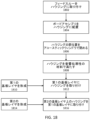
本明細書にはさらに、インプランタブルデバイスを作製する方法であって、フィードスルーをハウジングに取り付けることと、無線通信システムを備えるボードアセンブリをハウジング内に配置することと、ハウジングを第1の神経カフレイヤに取り付けることと、第1の神経カフレイヤを1つ以上の電極を備える第2の神経カフレイヤに取り付けることと、神経カフの1つ以上の電極を、フィードスルーを介してボードアセンブリに電気的に接続することとを含む、方法が記載される。いくつかの実施形態では、ボードアセンブリがハウジング内に配置される前に、フィードスルーがハウジングに取り付けられる。いくつかの実施形態では、ボードアセンブリがハウジング内に位置決めされる前に、フィードスルーがボードアセンブリに取り付けられる。いくつかの実施形態では、本方法は、ハウジングを封止することを含む。いくつかの実施形態では、本方法は、音響窓をハウジングに取り付けることを含む。いくつかの実施態様では、ボードアセンブリがハウジング内に配置された後に、音響窓がハウジングの開いた上部に取り付けられる。いくつかの実施態様において、本方法は、箔をフレームに取り付けることによって音響窓を組み立てることを含む。いくつかの実施形態では、この方法がハウジングに音響伝導性材料を充填することを含む。いくつかの実施形態では音響伝導性材料がハウジング上のポートを通してハウジング内に充填され、本方法はポートを封止することを含む。いくつかの実施形態では、この方法が無線通信システムをボードアセンブリに取り付けることを含む。いくつかの実施形態では、無線通信システムが1つ以上の超音波トランスデューサを備える。いくつかの実施形態では、ボードアセンブリが無線通信システムに電気的に接続された集積回路を備える。いくつかの実施形態では、ハウジングが第1の神経カフレイヤに直接取り付けられる。いくつかの実施形態では、接着剤またはファスナを使用して、ハウジングを第1の神経カフレイヤに取り付ける。いくつかの実施形態では、第1の神経カフレイヤは螺旋状である。いくつかの実施形態では、本方法は、1つ以上のハンドル部を本体、第1の神経カフレイヤ、第2の神経カフレイヤに、または第1の神経カフレイヤと第2の神経カフレイヤとの間に取り付けることを含む。いくつかの実施形態では、本方法は、基板材料に1つ以上の電極を埋め込むことによって、第2の神経カフレイヤを作製することを含む。いくつかの実施形態では、方法が第2の神経カフレイヤをマンドレル(軸体)の周りに巻くことと、第2の神経カフレイヤがマンドレルの周りに巻かれている間に、第2の神経カフレイヤを第1の神経カフレイヤに取り付けることと、を含む。 Further described herein is a method of making an implantable device, the method comprising: attaching a feedthrough to a housing; placing a board assembly with a wireless communication system in the housing; attaching the housing to a first nerve cuff layer; attaching the first nerve cuff layer to a second nerve cuff layer with one or more electrodes; and electrically connecting one or more electrodes of the nerve cuff to the board assembly via the feedthrough. In some embodiments, the feedthrough is attached to the housing before the board assembly is placed in the housing. In some embodiments, the feedthrough is attached to the board assembly before the board assembly is positioned in the housing. In some embodiments, the method comprises sealing the housing. In some embodiments, the method comprises attaching an acoustic window to the housing. In some implementations, the acoustic window is attached to the open top of the housing after the board assembly is placed in the housing. In some implementations, the method comprises assembling the acoustic window by attaching a foil to a frame. In some embodiments, the method comprises filling the housing with an acoustically conductive material. In some embodiments, the acoustically conductive material is filled into the housing through a port on the housing, and the method comprises sealing the port. In some embodiments, the method includes attaching a wireless communication system to the board assembly. In some embodiments, the wireless communication system includes one or more ultrasound transducers. In some embodiments, the board assembly includes an integrated circuit electrically connected to the wireless communication system. In some embodiments, the housing is attached directly to the first nerve cufflayer. In some embodiments, the housing is attached to the first nerve cufflayer using adhesives or fasteners. In some embodiments, the first nerve cufflayer is helical. In some embodiments, the method includes attaching one or more handle portions to the body, the first nerve cufflayer, the second nerve cufflayer, or between the first and second nerve cufflayers. In some embodiments, the method includes creating the second nerve cufflayer by embedding one or more electrodes in the substrate material. In some embodiments, the method includes wrapping the second nerve cufflayer around a mandrel and attaching the second nerve cufflayer to the first nerve cufflayer while the second nerve cufflayer is wrapped around the mandrel.
神経を刺激し、および/または神経によって伝達される電気生理学的信号(活動電位、または活動電位の非存在など)を検出するための1つ以上の電極を含むヘリカル神経カフが、本明細書に記載される。また、ヘリカル神経カフを動作させるように構成された本体を含む、ヘリカル神経カフを含むインプランタブルデバイスも記載される。身体は無線通信システムを含み、無線通信システムは、別のデバイスから指示を無線で受信するか、または別のデバイスに情報(検出された電気生理学的信号または他の生理学的特徴に関する情報など)を無線で送信することができる。また、ヘリカル神経カフおよびインプランタブルデバイスを埋め込む方法、ならびにヘリカル神経カフおよびインプランタブルデバイスを作製する方法も記載される。 Described herein is a helical nerve cuff that includes one or more electrodes for stimulating a nerve and/or detecting an electrophysiological signal (such as an action potential or the absence of an action potential) transmitted by a nerve. Also described is an implantable device that includes a helical nerve cuff, including a body configured to operate the helical nerve cuff. The body includes a wireless communication system that can wirelessly receive instructions from or wirelessly transmit information (such as information regarding a detected electrophysiological signal or other physiological characteristic) to another device. Also described are methods of implanting the helical nerve cuff and implantable device, as well as methods of making the helical nerve cuff and implantable device.
神経カフは、神経を含む線維組織の周りを少なくとも部分的に包むように構成されたヘリカル基板と、(例えば、長手に沿って)ヘリカル基板の内側表面上に配置された1つ以上の電極と、を含むことができる。ヘリカル神経カフは電極が神経と電気的に連通するように、被験体に埋め込むことができる。電極は、神経によって伝達される電気生理学的信号を検出するか、または神経に電気パルスを放出するように構成されてもよい。いくつかの実施形態では神経カフがヘリカル基板に取り付けられたハンドル部を含み、これは神経カフの埋め込みを容易にするために使用されてもよい。ヘリカル神経カフは患者の神経、例えば、脾神経または内臓神経にアクセスするのが困難な小さなおよび/またはそのいずれかに埋め込まれてよく、神経カフのらせん状のデザインにより、より容易な埋め込みが可能になる。 The nerve cuff may include a helical substrate configured to at least partially wrap around fibrous tissue containing a nerve, and one or more electrodes disposed on an inner surface of the helical substrate (e.g., along a length). The helical nerve cuff may be implanted in a subject such that the electrodes are in electrical communication with the nerve. The electrodes may be configured to detect electrophysiological signals transmitted by the nerve or to emit electrical pulses to the nerve. In some embodiments, the nerve cuff includes a handle portion attached to the helical substrate, which may be used to facilitate implantation of the nerve cuff. The helical nerve cuff may be implanted in small and/or difficult to access nerves of a patient, such as splenic or splanchnic nerves, and the helical design of the nerve cuff allows for easier implantation.
インプランタブルデバイスは無線通信システム(例えば、1つ以上の超音波トランスデューサまたは1つ以上の無線周波数(RF)アンテナを含み得る)と、無線通信システムと電気的に通信する2つ以上の電極と、ヘリカル神経カフとを有する本体を含む。2つ以上の電極は神経によって伝達される電気生理学的信号を検出するか、または神経に電気パルスを放出するように構成され、電極のうちの1つ以上はヘリカル神経カフ上に配置される。本体は導電性ハウジングを含んでもよく、それは、任意選択で電極の1つであってもよい。 The implantable device includes a body having a wireless communication system (which may include, for example, one or more ultrasound transducers or one or more radio frequency (RF) antennas), two or more electrodes in electrical communication with the wireless communication system, and a helical nerve cuff. The two or more electrodes are configured to detect electrophysiological signals transmitted by the nerve or emit electrical pulses to the nerve, and one or more of the electrodes are disposed on the helical nerve cuff. The body may include a conductive housing, which may optionally be one of the electrodes.
ヘリカル神経カフは神経(血管、すなわち神経血管束をさらに含んでもよい)を含む線維組織の一部を円周方向に切開し、線維組織の裏側を通して神経カフの端部を通し、ヘリカル神経カフを回転させて、線維組織の周りに神経カフを配置することによって、被験体に埋め込まれ得る。ヘリカル神経カフは、本体に取り付けられてもよく、デバイス本体はカフが線維組織の周辺に配置されるときに、線維組織の正面に配置されてもよい。ヘリカル神経カフが、ヘリカル神経の端部に取り付けられたハンドル部を含む場合、ハンドル部を線維組織の裏側を通して縫い付けて、ヘリカル神経カフの端部を線維組織の裏側を通して導くことができる。 The helical nerve cuff may be implanted in a subject by circumferentially incising a portion of the fibrous tissue containing the nerve (which may further include a blood vessel, i.e., a neurovascular bundle), threading an end of the nerve cuff through the back side of the fibrous tissue, and rotating the helical nerve cuff to position the nerve cuff around the fibrous tissue. The helical nerve cuff may be attached to a body, and the device body may be positioned in front of the fibrous tissue as the cuff is positioned around the fibrous tissue. If the helical nerve cuff includes a handle portion attached to the end of the helical nerve, the handle portion may be sewn through the back side of the fibrous tissue to guide the end of the helical nerve cuff through the back side of the fibrous tissue.
ヘリカル神経カフに取り付けられたハンドル部は神経カフが埋め込まれているときに、神経の小さなコンパートメント空間における神経カフの注意深い操作を可能にする。外科用把持ツールを使用して、ハンドル部を把持し、それを円周方向に切開された線維組織の裏側に通すことができる。いくつかの実施形態では、神経カフがヘリカル神経カフの反対側の端部に第2のハンドル部を含む。また、第2ハンドル部は神経カフを所定の位置に誘導し、埋め込み中にヘリックスを巻き戻し、またはヘリカル神経カフを回転させてデバイスを正しく位置決めするために、外科用把持具によって把持することもできる。 The handle portion attached to the helical nerve cuff allows for careful manipulation of the nerve cuff in the small compartment space of the nerve as it is implanted. A surgical grasping tool can be used to grasp the handle portion and pass it behind the circumferentially incised fibrous tissue. In some embodiments, the nerve cuff includes a second handle portion at the opposite end of the helical nerve cuff. The second handle portion can also be grasped by a surgical grasping tool to guide the nerve cuff into place, unwind the helix during implantation, or rotate the helical nerve cuff to properly position the device.
<定義>
本明細書で使用されるように、単数形「a」、「an」、および「the」は文脈が明らかにそわないことを指示しない限り、複数の参照を含む。
<Definition>
As used herein, the singular forms "a,""an," and "the" include plural references unless the context clearly dictates otherwise.
本明細書における値またはパラメータの「約」または「ほぼ」への基準は、その値またはパラメータ自体に向けられた変動を含む(および記述する)。例えば、「約X」を参照する記述には、「X」の記述が含まれる。 References herein to "about" or "approximately" a value or parameter include (and describe) a variation directed to the value or parameter itself. For example, a statement referring to "about X" includes the statement of "X."
本明細書に記載される本発明の態様および変形は、「からなる」および/または「本質的にからなる」態様および変形を含むことが理解される。 It is understood that the aspects and variations of the invention described herein include aspects and variations that "consist of" and/or "consist essentially of".
用語「被験体」および「患者」は、本明細書において、脊椎動物を指すために互換的に使用される。 The terms "subject" and "patient" are used interchangeably herein to refer to a vertebrate animal.
用語「処置する」、「処置すること」、および「処置」は、本明細書中で同義的に使用され、少なくとも1つの症状の軽減、阻害、抑制、または排除による状態の改善、疾患または状態の進行の遅延、疾患または状態の再発の遅延、または疾患または状態の阻害を含む、疾患状態または状態に罹患した被験体に利益を提供する任意のアクションをいう。 The terms "treat," "treating," and "treatment" are used interchangeably herein and refer to any action that provides a benefit to a subject afflicted with a disease state or condition, including improving the condition by reducing, inhibiting, suppressing, or eliminating at least one symptom, slowing the progression of the disease or condition, slowing the recurrence of the disease or condition, or inhibiting the disease or condition.
値の範囲が提供される場合、その範囲の上限と下限との間の各介在値、およびその記載された範囲内の任意の他の記載または介在値は、本開示の範囲内に包含されることが理解されるべきである。記載された範囲が上限または下限を含む場合、それらのいずれかを除外する範囲もまた、本開示に含まれる。 When a range of values is provided, it is to be understood that each intervening value between the upper and lower limits of that range, and any other stated or intervening value within that stated range, is encompassed within the scope of the disclosure. When a stated range includes an upper or lower limit, ranges excluding either of those limits are also included in the disclosure.
本明細書で説明される様々な実施形態の特性のうちの1つ、いくつか、またはすべてを組み合わせて、本発明の他の実施形態を形成することができることを理解されたい。本明細書で使用される項目見出しは、構成的な目的のためでしかなく、説明される主題を限定すると解釈すべきではない。 It is to be understood that one, some, or all of the features of the various embodiments described herein may be combined to form other embodiments of the present invention. The section headings used herein are for organizational purposes only and should not be construed as limiting the subject matter described.
「実施形態」に関連して上述した特徴および選好は別個の選好であり、その特定の実施形態のみに限定されるものではなく、技術的に実現可能な他の実施形態からの特徴と自由に組み合わせることができ、特徴の好ましい組み合わせを形成することができる。この説明は当業者が本発明を実施し、使用することを可能にするために提示され、特許出願およびその要件の文脈で提供される。記載された実施形態に対する種々の変形は当業者に容易に明らかであり、本明細書の一般的な原理は、他の実施形態に適用されてもよい。したがって、本発明は、示された実施形態に限定されることを意図するものではなく、本明細書に記載された原理および特徴と一致する最も広い範囲を与えられるべきである。 The features and preferences described above in connection with the "embodiments" are separate preferences and are not limited to that particular embodiment, but can be freely combined with features from other embodiments where technically feasible to form preferred combinations of features. This description is presented to enable one of ordinary skill in the art to make and use the invention and is provided in the context of a patent application and its requirements. Various modifications to the described embodiments will be readily apparent to those skilled in the art, and the generic principles herein may be applied to other embodiments. Thus, the present invention is not intended to be limited to the embodiments shown, but is to be accorded the widest scope consistent with the principles and features described herein.
<ヘリカル神経カフ>
ヘリカル神経カフは、神経を含む線維組織の周りを少なくとも部分的に巻くように構成されたヘリカル基板と、ヘリカル基板の長さに沿って配置された1つ以上の電極とを含む。神経カフは任意選択で、1つ以上のハンドル部、例えば、ヘリカル基板の端部に取り付けられたハンドル部を含むことができる。
<Helical Nerve Cuff>
The helical nerve cuff includes a helical substrate configured to at least partially wrap around fibrous tissue containing a nerve and one or more electrodes disposed along a length of the helical substrate. The nerve cuff can optionally include one or more handle portions, for example, handle portions attached to an end of the helical substrate.
神経カフは、神経を含む線維組織の周りを少なくとも部分的に巻くように構成される。線維組織は神経に加えて、血管(例えば、神経血管束)などの線維組織を含んでもよい。例えば、脾神経は脾動脈と密接に関連付けられ、神経カフは、脾神経と脾動脈の両方を少なくとも部分的に包むように構成されてもよい。ヘリカル神経カフの内径は、被験体の種類、ターゲット神経、または被験体内の他の解剖学的差異(例えば、特定の被験体内の神経のサイズ)に応じて異なり得る線維組織の直径に基づいて選択されてもよい。例として、内径は直径が約1mm~約8mm(例えば、直径が約1mm~約2mm、約2mm~約3mm、約3mm~約4mm、約4mm~約5mm、約5mm~約6mm、約6mm~約7mm、または約7mm~約8mm)であってもよい。 The nerve cuff is configured to at least partially wrap around fibrous tissue including a nerve. In addition to nerves, the fibrous tissue may include fibrous tissue such as blood vessels (e.g., neurovascular bundles). For example, the splenic nerve is closely associated with the splenic artery, and the nerve cuff may be configured to at least partially encase both the splenic nerve and the splenic artery. The inner diameter of the helical nerve cuff may be selected based on the diameter of the fibrous tissue, which may vary depending on the type of subject, the target nerve, or other anatomical differences within the subject (e.g., the size of the nerve within a particular subject). By way of example, the inner diameter may be about 1 mm to about 8 mm in diameter (e.g., about 1 mm to about 2 mm, about 2 mm to about 3 mm, about 3 mm to about 4 mm, about 4 mm to about 5 mm, about 5 mm to about 6 mm, about 6 mm to about 7 mm, or about 7 mm to about 8 mm in diameter).
ヘリカル神経カフは、少なくとも1回転、神経の周りを巻くように構成されてもよい。例えば、ヘリカル神経カフは、約1~約1.3回転、約1.3~約1.7回転、約1.7~約2回転、約2~約2.5回転、約2.5~約3回転、または約3~約4回転など、約1~約4回転、神経の周りを巻くことができる。いくつかの実施形態では、ヘリカル神経カフが約1.5回転、神経の周りを巻くように構成される。 The helical nerve cuff may be configured to wrap around the nerve at least one turn. For example, the helical nerve cuff can wrap around the nerve about 1 to about 4 turns, such as about 1 to about 1.3 turns, about 1.3 to about 1.7 turns, about 1.7 to about 2 turns, about 2 to about 2.5 turns, about 2.5 to about 3 turns, or about 3 to about 4 turns. In some embodiments, the helical nerve cuff is configured to wrap around the nerve about 1.5 turns.
神経カフの基板は、らせん形状に巻かれた細長い材料である。ヘリカル基板は、実質的に平坦な内側表面および/または実質的に平坦な外側表面を有してもよい。基板の幅は、実質的に均一であってもよく、任意選択で、テーパ状または丸みを帯びた端部を有してもよい。基板の幅は縁部(エッジ)を定義し、縁部は神経カフが弛緩位置にあるとき、基板がらせん形状に巻かれるにつれて、互いに接触してもよく、または接触しなくてもよい。例えば、いくつかの実施形態では、ギャップが基板の回転を分離しても分離しなくてもよい。いくつかの実施形態では基板が内側表面、基板の第1の縁部、および基板の第2の縁部を定義する幅を有し、神経カフが弛緩位置にあるとき、第1の縁部の少なくとも一部分は第2の縁部の少なくとも一部分に接触する。いくつかの実施形態では、基板が内側表面、基板の第1の縁部、および基板の第2の縁部を定義する幅を有し、神経カフが弛緩位置にあるとき、第1の縁部は第2の縁部に接触しない。 The substrate of the nerve cuff is an elongated material wound into a helical shape. The helical substrate may have a substantially flat inner surface and/or a substantially flat outer surface. The width of the substrate may be substantially uniform and may optionally have tapered or rounded ends. The width of the substrate defines edges, which may or may not contact each other as the substrate is wound into a helical shape when the nerve cuff is in a relaxed position. For example, in some embodiments, a gap may or may not separate the turns of the substrate. In some embodiments, the substrate has a width defining an inner surface, a first edge of the substrate, and a second edge of the substrate, and when the nerve cuff is in a relaxed position, at least a portion of the first edge contacts at least a portion of the second edge. In some embodiments, the substrate has a width defining an inner surface, a first edge of the substrate, and a second edge of the substrate, and when the nerve cuff is in a relaxed position, the first edge does not contact the second edge.
ヘリカル神経カフの基板は、生体適合性および/またはエラストマー材料であり得る絶縁材料から作製される。例示的な基板材料にはシリコーン、シリコーンゴム、ポリジメチルシオロキサン(PDMS)、ウレタンポリマー、ポリ(p-キシリレン)ポリマー(PARYLENE(登録商標)の商品名で販売されているポリ(p-キシリレン)ポリマーなど)、またはポリイミドが含まれるが、これらに限定されない。 The substrate of the helical nerve cuff is made from an insulating material, which may be a biocompatible and/or elastomeric material. Exemplary substrate materials include, but are not limited to, silicone, silicone rubber, polydimethylsiloxane (PDMS), urethane polymers, poly(p-xylylene) polymers (such as poly(p-xylylene) polymers sold under the trade name PARYLENE®), or polyimide.
いくつかの実施形態では、ヘリカル神経カフの基板が同じ材料であっても異なる材料であってもよい2つ以上のレイヤを含んでもよい。レイヤはヘリカル神経カフの内側表面(inner surface)を形成し、線維組織に接触する内側レイヤと、ヘリカル神経カフの外側表面(outer surface)を形成する外側レイヤとを含むことができる。導電性材料は、ヘリカル神経カフの電極を形成することができる内側レイヤと外側レイヤとの間に配置することができる。例えば、内側レイヤは電極を規定する導電性材料を露出させるために、内面上に1つ以上の開口部を含むことができる。別個の内側レイヤ及び外側レイヤは、基板のらせん形状をさらに規定することができる。例えば、内側レイヤはヘリカル神経カフが屈曲構成にあるときに外側レイヤよりも高い張力下にあってもよく、これはヘリカル神経カフが弛緩構成にあるときに基板を内側に強制的にカールさせる。 In some embodiments, the substrate of the helical nerve cuff may include two or more layers, which may be of the same or different materials. The layers may include an inner layer that forms the inner surface of the helical nerve cuff and contacts the fibrous tissue, and an outer layer that forms the outer surface of the helical nerve cuff. A conductive material may be disposed between the inner and outer layers, which may form the electrodes of the helical nerve cuff. For example, the inner layer may include one or more openings on an inner surface to expose the conductive material that defines the electrodes. The separate inner and outer layers may further define the helical shape of the substrate. For example, the inner layer may be under higher tension than the outer layer when the helical nerve cuff is in a bent configuration, which forces the substrate to curl inward when the helical nerve cuff is in a relaxed configuration.
神経カフの幅は神経カフの長さ(すなわち、神経カフの両端間のらせんの中央を走る軸に沿った最大距離)、基板の回転数、基板回転間のギャップの大きさ(もしあれば)に依存することができる。いくつかの実施形態では、神経カフの長さは約4mm~約20mm(例えば、約4mm~約7mm、約7m~約10mm、約10mm~約13mm、約13mm~約16mm、または約16mm~約20mm)である。いくつかの実施形態では、基板の幅(または内側幅)が約2mm~約8mm(例えば、約2mm~約4mm、約4mm~約6mm、または約6mm~約8mm)である。 The width of the nerve cuff can depend on the length of the nerve cuff (i.e., the maximum distance along the axis running through the center of the helix between the two ends of the nerve cuff), the number of rotations of the substrate, and the size of the gap (if any) between substrate rotations. In some embodiments, the length of the nerve cuff is about 4 mm to about 20 mm (e.g., about 4 mm to about 7 mm, about 7 mm to about 10 mm, about 10 mm to about 13 mm, about 13 mm to about 16 mm, or about 16 mm to about 20 mm). In some embodiments, the width (or inner width) of the substrate is about 2 mm to about 8 mm (e.g., about 2 mm to about 4 mm, about 4 mm to about 6 mm, or about 6 mm to about 8 mm).
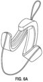
神経カフは、埋め込みの際に神経カフの操作を可能にするために可撓性であってもよい。例えば、いくつかの実施形態では、ヘリカル神経カフがヘリカル神経カフを少なくとも部分的に巻き戻すことによって屈曲位置に、およびヘリカル神経カフをヘリカル構成にして弛緩位置に構成することができる。図6Aは屈曲位置にある例示的なヘリカル神経カフを示し、神経カフの右巻きらせん部および左巻きらせん部の両方が一緒に接合され、右巻きらせん部および左巻きらせん部のいずれかの端部に一方向に取り付けられた第1のハンドル部および第2のハンドル部を引っ張り、接合部材に取り付けられた第3のハンドル部を反対方向に引っ張ることによって部分的に巻き戻される。図6Bは、弛緩位置にある、図6Aに示されるのと同じヘリカル神経カフを示す。 The nerve cuff may be flexible to allow manipulation of the nerve cuff during implantation. For example, in some embodiments, a helical nerve cuff can be configured in a flexed position by at least partially unwinding the helical nerve cuff, and in a relaxed position by placing the helical nerve cuff in a helical configuration. FIG. 6A shows an exemplary helical nerve cuff in a flexed position, with both the right-handed and left-handed helical portions of the nerve cuff joined together and partially unwound by pulling the first and second handle portions attached to either end of the right-handed and left-handed helical portions in one direction and pulling the third handle portion attached to the joining member in the opposite direction. FIG. 6B shows the same helical nerve cuff shown in FIG. 6A in a relaxed position.
神経カフには、右巻きらせん部、左巻きらせん部、または両者の右巻きらせん部、左巻きらせん部が含まれることがある。例えば、いくつかの実施形態では、神経カフが直接的に、または接続部材(直線状、湾曲状、またはヒンジ式であってもよい)を介して、左巻きらせん部に接合された右巻きらせん部を含んでもよい。 The nerve cuff may include a right-handed helix, a left-handed helix, or both. For example, in some embodiments, the nerve cuff may include a right-handed helix joined to a left-handed helix, either directly or via a connecting member (which may be straight, curved, or hinged).
神経カフの1つ以上の電極は神経カフ基板の内側表面上に配置されてもよく、被覆されなくてもよく、または導電性材料(例えば、電極の電気特性を改善するために、ポリ(3,4-エチレンジオキシチオフェン)(PEDOT)ポリマーもしくは他の導電性ポリマーまたは金属で電気めっきされてもよい)で被覆されてもよい。いくつかの実施形態では、1つ以上の電極は点電極である。いくつかの実施形態では、1つ以上の電極が細長くてもよく、例えば、ヘリカル基板の長さに沿って配置されてもよい。電極は、基板の端部の前、基板の端部、または基板の端部を越えて終端することができる。1つ以上の電極はヘリカル神経カフ上のフィードスルーに接続され得、これは電極が基板の外側表面または神経カフの外側表面に取り付けられた本体に電気的に接続されることを可能にする。 The one or more electrodes of the nerve cuff may be disposed on the inner surface of the nerve cuff substrate and may be uncoated or coated with a conductive material (e.g., may be electroplated with poly(3,4-ethylenedioxythiophene) (PEDOT) polymer or other conductive polymer or metal to improve the electrical properties of the electrode). In some embodiments, the one or more electrodes are point electrodes. In some embodiments, the one or more electrodes may be elongated, e.g., disposed along the length of the helical substrate. The electrodes may terminate before the end of the substrate, at the end of the substrate, or beyond the end of the substrate. The one or more electrodes may be connected to a feedthrough on the helical nerve cuff, which allows the electrodes to be electrically connected to the outer surface of the substrate or to a body attached to the outer surface of the nerve cuff.
神経カフは、1個、2個、3個、4個、5個、6個、7個、8個、9個、10個またはそれ以上の電極のような1個またはそれ以上の電極を含む。いくつかの実施形態では、電極のうちの1つ以上が神経に電気パルスを放出するように構成される。いくつかの実施形態では、神経カフが神経に電気パルスを放出するように構成された1、2、3、4、5、6、7、8、9、10個以上の電極を含む。いくつかの実施形態では、電極のうちの1つ以上が神経によって伝達される電気生理学的信号を検出するように構成される。いくつかの実施形態では、神経カフが神経によって伝達される電気生理学的信号を検出するように構成された1、2、3、4、5、6、7、8、9、10個以上の電極を含む。いくつかの実施形態では1つ以上の電極が神経に電気パルスを放出するように構成され、1つ以上の電極は神経によって伝達される電気生理学的信号を検出するように構成される。いくつかの実施形態では、電気パルスを放出するように構成された電極が電気生理学的信号を検出するように構成された電極よりも幅が広い。(2つ以上の電極を有する)ヘリカル神経カフの電極は、ヘリカル神経カフの長さに沿って、互いに並んで、または異なる方向に配置されてもよい。 The nerve cuff includes one or more electrodes, such as 1, 2, 3, 4, 5, 6, 7, 8, 9, 10 or more electrodes. In some embodiments, one or more of the electrodes are configured to emit an electrical pulse to the nerve. In some embodiments, the nerve cuff includes 1, 2, 3, 4, 5, 6, 7, 8, 9, 10 or more electrodes configured to emit an electrical pulse to the nerve. In some embodiments, one or more of the electrodes are configured to detect an electrophysiological signal transmitted by the nerve. In some embodiments, the nerve cuff includes 1, 2, 3, 4, 5, 6, 7, 8, 9, 10 or more electrodes configured to detect an electrophysiological signal transmitted by the nerve. In some embodiments, one or more electrodes are configured to emit an electrical pulse to the nerve and one or more electrodes are configured to detect an electrophysiological signal transmitted by the nerve. In some embodiments, the electrodes configured to emit an electrical pulse are wider than the electrodes configured to detect an electrophysiological signal. The electrodes of a helical nerve cuff (having two or more electrodes) may be positioned alongside one another or in different directions along the length of the helical nerve cuff.
任意選択で、神経カフ上の1つ以上の電極は蛇行構成、または1つ以上の(例えば、2、3、4、または複数の)蛇行セグメントを有する。図19Bは、非蛇行セグメント1916によって分離された第1の蛇行セグメント1914aおよび第2の蛇行セグメント1914bを有する電極1908の例を示す。電極の蛇行構成は電極および神経カフの柔軟性を高めることを可能にし、これは、神経カフを埋め込む場合に特に有益である。脾神経などの特定の末梢神経は埋め込みおよび配置の際に神経カフの大幅な操作および屈曲を必要とすることがあるため、蛇行構成により、埋め込みの際の神経カフまたは電極損傷の可能性を低下させることができる。
Optionally, one or more electrodes on the nerve cuff have a serpentine configuration or one or more (e.g., two, three, four, or multiple) serpentine segments. FIG. 19B shows an example of an
任意のハンドル部は外科用把持ツール(例えば、鉗子、フック、または他の把持または把持器具)によって把持されるように構成され、埋め込み中にヘリカル神経カフを操作するために有用であり得る。ハンドル部はヘリカル基板から延びるか、またはヘリカル基板内に部分的に埋め込まれてもよく、ハンドル部の把持および神経カフの操作を容易にするために、基板よりも可撓性が高いおよび/または薄くてもよい。ハンドル部は、例えばハンドル部内に、またはハンドル部のいずれかの端部が基板に取り付けられることによってループを形成することによって、ループを含んでもよい。いくつかの実施形態ではハンドル部が可撓性フィラメント(糸、紐、コード、縫合糸、またはワイヤなど)を含み、これは対象内に埋め込まれると任意選択で生分解性である。いくつかの実施形態では、ハンドル部がポリグリコリド、ポリジオキサノン、ポリカプロラクトン、またはそれらのコポリマーなどの生体吸収性材料を含む。 The optional handle portion may be configured to be grasped by a surgical grasping tool (e.g., forceps, hook, or other grasping or gripping instrument) and may be useful for manipulating the helical nerve cuff during implantation. The handle portion may extend from or be partially embedded within the helical substrate and may be more flexible and/or thinner than the substrate to facilitate grasping of the handle portion and manipulation of the nerve cuff. The handle portion may include a loop, for example, within the handle portion or by forming a loop by attaching either end of the handle portion to the substrate. In some embodiments, the handle portion includes a flexible filament (such as a thread, string, cord, suture, or wire), which is optionally biodegradable once implanted within a subject. In some embodiments, the handle portion includes a bioabsorbable material, such as polyglycolide, polydioxanone, polycaprolactone, or copolymers thereof.
任意のハンドル部は神経カフの端部に近位で(例えば、ヘリカル神経カフの先端で)神経カフに取り付けられてもよい。神経カフは、任意選択で、2つ以上のハンドル部を含む。例えば、ヘリカル部は、ヘリカル基板の反対側の端部に近位の追加のハンドル部、および/またはヘリカル基板の中間部分に近位の追加のハンドル部を含むことができる。ヘリカル神経カフが本体に取り付けられる場合、本明細書でさらに論じられるように、ハンドル部のうちの1つは、本体に近位であっても、本体に遠位であってもよい。例として、いくつかの実施形態では本体がヘリカル神経カフの第1の端部に近位に取り付けられ、ハンドルはヘリカル神経カフの第2の端部に近位に取り付けられる。いくつかの実施形態では本体がヘリカル神経カフの第1の端部の近位に取り付けられ、ハンドル部はヘリカル神経カフの第1の端部の近位に取り付けられる。いくつかの実施形態では本体がヘリカル神経カフの第1の端部の近位に取り付けられ、第1のハンドル部は本体の近位に取り付けられ、第2のハンドル部はヘリカル神経カフの第2の端部の近位に取り付けられる。いくつかの実施形態では本体がヘリカル神経カフの中間部分に取り付けられ、第1のハンドル部はヘリカル神経カフの第1の端部の近位に取り付けられ、第2のハンドル部は本体の近位に取り付けられ、任意選択で、第3のハンドル部はヘリカル神経カフの第2の端部の近位に取り付けられる。 Any handle portion may be attached to the nerve cuff proximal to the end of the nerve cuff (e.g., at the tip of a helical nerve cuff). The nerve cuff optionally includes two or more handle portions. For example, the helical portion may include an additional handle portion proximal to the opposite end of the helical substrate and/or an additional handle portion proximal to the intermediate portion of the helical substrate. When the helical nerve cuff is attached to the body, one of the handle portions may be proximal to the body or distal to the body, as discussed further herein. By way of example, in some embodiments the body is attached proximal to the first end of the helical nerve cuff and the handle is attached proximal to the second end of the helical nerve cuff. In some embodiments the body is attached proximal to the first end of the helical nerve cuff and the handle portion is attached proximal to the first end of the helical nerve cuff. In some embodiments, the body is attached proximal to the first end of the helical nerve cuff, the first handle portion is attached proximal to the body, and the second handle portion is attached proximal to the second end of the helical nerve cuff. In some embodiments, the body is attached to an intermediate portion of the helical nerve cuff, the first handle portion is attached proximal to the first end of the helical nerve cuff, the second handle portion is attached proximal to the body, and optionally, a third handle portion is attached proximal to the second end of the helical nerve cuff.
任意選択的に、神経カフに取り付けられた2つ以上のハンドル部が互いに接合される。例えば、第1のハンドル部はヘリカル神経カフの第1の端部の近位に取り付けられた第1の端部を含み、第2のハンドル部はヘリカル神経カフの第2の端部の近位に取り付けられた第1の端部を含み、第1のハンドル部の第2の端部および第2のハンドル部の第2の端部は、互いに接合される。第1のハンドル部および第2のハンドル部はらせん軸の周りに約90°~約180°(例えば、約90°~約120°、約120°~約150°、または約150°~約180°)の半径方向角度で分離されたヘリカル神経カフに取り付けられてもよい。 Optionally, two or more handle portions attached to the nerve cuff are joined together. For example, a first handle portion includes a first end attached proximal to a first end of the helical nerve cuff, a second handle portion includes a first end attached proximal to a second end of the helical nerve cuff, and the second end of the first handle portion and the second end of the second handle portion are joined together. The first handle portion and the second handle portion may be attached to the helical nerve cuff separated by a radial angle of about 90° to about 180° (e.g., about 90° to about 120°, about 120° to about 150°, or about 150° to about 180°) about the helical axis.
図1Aは例示的なヘリカル神経カフを図示し、これは、本明細書中に記載されるインプランタブルデバイスの一部であり得る。図1Bは、異なる角度からの図1Aに示される神経カフを示す。神経カフ100は、外側レイヤ104および内側レイヤ106を含むヘリカル基板102を含む。神経カフは約1.5回転だけ神経の周りに巻き付くように構成され、ギャップ114は基板の回転を分離する。基板102は左巻きらせんとして構成されるが、右巻きらせんの基板を有する実施形態も考えられる。細長い電極108は、ヘリカル基板102の内側表面に配置される。細長い電極108はフィードスルーポート110から伸長し、ヘリカル基板102の端部112の前の位置で終わる。電極108は外側レイヤ104と内側レイヤ106との間にあり、内側レイヤ106は、電極108を神経カフ100の内側表面に露出させる細長い切欠きを含む。代替の実施形態では、電極が内側レイヤ106の上部に配置される。図1Dおよび図1Eは、ハウジング122を有する本体に取り付けられた図1Aおよび図1Bのヘリカル神経カフを示す。ハウジング122は、ヘリカル神経カフ基板102の外側表面に取り付けられる。フィードスルー124は、フィードスルーポート110を通過して、細長い電極108を本体に電気的に接続する。
FIG. 1A illustrates an exemplary helical nerve cuff, which may be part of an implantable device described herein. FIG. 1B illustrates the nerve cuff shown in FIG. 1A from a different angle. The
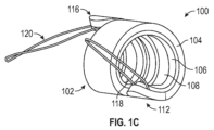
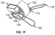
図1Cは図1Aおよび図1Bに示される神経カフに類似する例示的なヘリカル神経カフを示すが、基板102の第1の端部112の近位のヘリカル基板102に取り付けられた第1のハンドル部118と、基板102の第2の端部116の近位のヘリカル基板102に取り付けられた第2のハンドル部120とをさらに含む。第1のハンドル部118および第2のハンドル部120はそれぞれ、ループを形成する可撓性フィラメントであり、フィラメントの各端部は、基板102に取り付けられる。フィラメントの端部は、内側レイヤ106と外側レイヤ104との間の基板102内に埋め込まれている。図1Fは、ハウジング122を有する本体に取り付けられた図1Cのヘリカル神経カフを示す。ハウジング122は、ヘリカル神経カフ基板102の外側表面に取り付けられる。
1C shows an exemplary helical nerve cuff similar to the nerve cuff shown in FIGS. 1A and 1B, but further including a
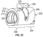
図2Aおよび図2Bは、それぞれ、ヘリカル神経カフ200の別の実施形態の前方および後方斜視図を示す。神経カフ200は、接続部材208を介して互いに接合された左巻きヘリカルセグメント204および右巻きヘリカルセグメント206を有する基板202を含む。図示された神経カフ200の接続部材208は、神経の周りを完全に1回転よりもわずかに少なく回転する、基板202の湾曲した細長い部分である。フィードスルーポート210は接続部材208に沿って配置され、これにより、本体を基板の内側表面に配置された電極に電気的に接続することができる。基板202は外側レイヤ212と内側レイヤ214とを含み、外側レイヤ212と内側レイヤ214との間に導電性の中間レイヤ216を挟んで導電性を有する。ヘリカル神経カフは、左巻きヘリカルセグメント204における基板202の内側表面上の神経によって伝達される電気生理学的信号を検出するように構成された3つの並列な細長い電極(218、220、および222)と、右巻きヘリカルセグメント206における基板202の内側表面上の神経に電気パルスを放出するように構成された第4の細長い電極224とを含む。電極は、内側レイヤ214の開口部によって画定される。図示の実施形態では、第4の細長い電極224が電極218、220、および222よりも幅が広い。図2Cは、ハウジング226を有する本体に取り付けられた図2Aおよび図2Bのヘリカル神経カフを示す。ハウジング226は、接続部材208においてヘリカル神経カフの基板202の外側表面に取り付けられる。フィードスルー228は、電極218、220、222、および224を本体に電気的に接続するところでフィードスルーポート210を通過する。
2A and 2B show anterior and posterior perspective views, respectively, of another embodiment of a
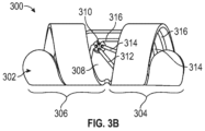
図3Aおよび図3Bは、それぞれ、ヘリカル神経カフ300の別の実施形態の前方および底面の斜視図を示す。神経カフ300は、接続部材308を介して互いに接合された左巻きヘリカルセグメント304および右巻きヘリカルセグメント306を有する基板302を含む。図示された神経カフ300の接続部材308は基板302の湾曲した細長い部分であり、図2Aおよび図2Bに図示された神経カフの接続部材よりもより短い。フィードスルーポート310は接続部材308に沿って配置され、これにより、本体を基板の内側表面に配置された電極に電気的に接続することができる。図示された神経カフ300の基板302は、基板302の内側表面に沿って配置された電極を有する単一層を含む。ヘリカル神経カフは、左巻きのヘリカルセグメント304における基板302の内側表面上の3つの細長い電極(312、314、および316)と、右巻きのヘリカルセグメント306における基板302の内側表面上の第4の細長い電極318とを含む。図3Cは、ハウジング320を有する本体に取り付けられた図3Aおよび図3Bのヘリカル神経カフを示す。ハウジング320は、ヘリカル神経カフ基板302の外側表面に取り付けられる。
3A and 3B show front and bottom perspective views, respectively, of another embodiment of a
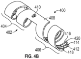
図4Aおよび図4Bは、それぞれ、ヘリカル神経カフ400の別の実施形態の下面図および上面図を示す。神経カフ400は、接続部材408を介して互いに接合された左巻きヘリカルセグメント404および右巻きヘリカルセグメント406を有する基板402を含む。図示された神経カフ400の接続部材408は、細長く直線状の接続部材である。フィードスルーポート410は接続部材408に沿って配置され、これにより、本体が、基板の内側表面に配置された電極に電気的に接続されることが可能になる。図示された神経カフ400の基板402は、基板402の内側表面に沿って配置された電極を有する単一層を含む。ヘリカル神経カフは左巻きヘリカルセグメント404における基板402の内面上に3つの並列細長い電極(412、414、および416)を含み、神経カフ400の端部418を越えて延在する。図示の実施形態では電極412、414、および416は接合端420で互いに接合されている。神経カフはさらに、右巻きヘリカルセグメント406において基板402の内側表面に第4の細長い電極422を含み、これは、神経カフ400の反対側の端部424を越えて延在する。
4A and 4B show bottom and top views, respectively, of another embodiment of a
図5Aおよび図5Bは、それぞれ、ヘリカル神経カフ500の別の実施形態の下面図および上面図を示す。神経カフ500は、接続部材508を介して互いに接合された第1の左巻きヘリカルセグメント504および第2の左巻きヘリカルセグメント506を有する基板502を含む。図示された神経カフ500の接続部材508は、細長く直線状の接続部材である。フィードスルーポート510は接続部材508に沿って配置され、これにより、本体が、基板の内側表面に配置された電極に電気的に接続されることが可能になる。図示された神経カフ500の基板502は、基板502の内側表面に沿って配置された電極を有する単一層を含む。ヘリカル神経カフは第1の左巻きヘリカルセグメント504において基板502の内側表面上に3つの並列な細長い電極(512、514、および516)を含み、神経カフ500の端部518を越えて延在する。神経カフはさらに、神経カフ500の反対側の端部522を越えて延在する、第2の左巻きヘリカルセグメント506における基板502の内側表面上の第4の細長い電極520を含む。
5A and 5B show bottom and top views, respectively, of another embodiment of a
ヘリカル神経カフは、任意選択で、本体を受容するように構成されたマウントを含むことができる。マウントは本体がヘリカル神経カフから外れないように、デバイスに追加の安定性を提供する。マウントはヘリカル神経カフの基板に、例えばヘリカル神経カフの外側表面に、またはヘリカル神経カフの端部に取り付けることができる。マウントは、ヘリカル神経カフの基板の端部を受容するような大きさおよび形状の基板受容ポートを含むことができる。ヘリカル神経カフの1つ以上の電極は基板自体よりも基板受容ポート内により深く配置され得るように、基板の末端を越えて延在してもよい。マウントはまた、本体を収容する本体またはハウジングを受け入れるような大きさおよび形状にされた本体受容ポートを含むことができる。したがって、マウントは、ヘリカル神経カフの基板への本体の安定した取り付けを提供することができる。本明細書にさらに記載されるように、本体は、ヘリカル神経カフ上の1つ以上の電極を操作するための構成要素を含み得る。したがって、マウントは、本体とヘリカル神経カフの1つ以上の電極との間の電気的接続を提供する。これは、例えば、ヘリカル神経カフの1つ以上の電極と本体との間の直接的な接続を可能にすることによって生じ得る。例えば、マウントは本体と1つ以上の電極との間の電気的接続を可能にするために、基板受容ポートと本体受容ポートとを接続する開口部を含むことができる。あるいは、マウントが本体とヘリカル神経カフ上の1つ以上の電極との間の電気的接続の中間にある1つ以上の電気フィードスルーを含むことができる。 The helical nerve cuff may optionally include a mount configured to receive the body. The mount provides additional stability to the device such that the body does not become dislodged from the helical nerve cuff. The mount may be attached to the substrate of the helical nerve cuff, for example, to the outer surface of the helical nerve cuff, or to the end of the helical nerve cuff. The mount may include a substrate receiving port sized and shaped to receive the end of the substrate of the helical nerve cuff. One or more electrodes of the helical nerve cuff may extend beyond the end of the substrate such that they may be positioned deeper into the substrate receiving port than the substrate itself. The mount may also include a body receiving port sized and shaped to receive a body or housing that houses the body. Thus, the mount may provide a stable attachment of the body to the substrate of the helical nerve cuff. As further described herein, the body may include components for manipulating one or more electrodes on the helical nerve cuff. Thus, the mount provides an electrical connection between the body and one or more electrodes of the helical nerve cuff. This may occur, for example, by allowing a direct connection between one or more electrodes of the helical nerve cuff and the body. For example, the mount can include an opening connecting the substrate receiving port and the body receiving port to allow electrical connection between the body and the one or more electrodes. Alternatively, the mount can include one or more electrical feedthroughs intermediate the electrical connection between the body and the one or more electrodes on the helical nerve cuff.
マウントは、生体適合性および/またはエラストマー材料とすることができる絶縁材料で作ることができる。マウントのための例示的な材料としてはシリコン、シリコンゴム、ポリエーテルエーテルケトン(PEEK)、ポリジメチルシオロキサン(PDMS)、ウレタンポリマ、ポリ(p-キシリレン)ポリマ(PARYLENE(登録商標)の商品名で販売されているポリ(p-キシリレン)ポリマーなど)、またはポリイミドが挙げられるが、これらに限定されない。 The mount can be made of an insulating material, which can be a biocompatible and/or elastomeric material. Exemplary materials for the mount include, but are not limited to, silicone, silicone rubber, polyetheretherketone (PEEK), polydimethylsiloxane (PDMS), urethane polymers, poly(p-xylylene) polymers (such as poly(p-xylylene) polymers sold under the trade name PARYLENE®), or polyimide.
図19A~19Cは、基板1906に取り付けられた本体1904を受容するように構成されたマウント1902を有する例示的なヘリカル神経カフを示す。基板1906はヘリカル基板の内内側表面上の電極1908が見えるように、透明として示される。図19Cを参照すると、マウント1902は、基板受容ポート1920および本体受容ポート1918を含む。図19Bに示されるように、基板1906は、マウント1902の基板受容ポート1920によって受容され得る末端1912を含み得る。電極1908は、基板1906の末端1912を越えて延在する延長部1910を含むことができる。マウントが基板に取り付けられると、電極1908の延長部1910は、末端1912よりも基板受容ポート1920内の深い位置に配置される(図19A参照)。本体1904を、本体受容ポート1918を通して取り付けることにより、本体1904と電極1908との間の電気的接続が、電極1908の延長部1910を通して可能になる。
19A-19C show an exemplary helical nerve cuff having a
いくつかの実施形態では、ヘリカル神経カフが被験体に埋め込まれる。被験体は例えば、哺乳動物であり得る。いくつかの実施形態では、被験体はヒト、イヌ、ネコ、ウマ、ウシ、ブタ、ヒツジ、ヤギ、サル、またはげっ歯類(ラットまたはマウスなど)である。ヘリカル神経カフは、これらの動物のいずれか、または他の動物内の線維組織(末梢神経、または神経血管束などの末梢神経を含む線維組織など)の周りを少なくとも部分的に巻くように構成されてもよい。例えば、いくつかの実施形態では、ヘリカル神経カフが人間(ヒト)の脾神経、または人間の脾神経血管束などの人間の末梢神経の周りを少なくとも部分的に巻くように構成される。いくつかの実施形態では、ヘリカル神経カフがヒトの内臓神経などのヒトの末梢神経の周りを少なくとも部分的に巻くように構成される。いくつかの実施形態では、ヘリカル神経カフが自律神経の周りを少なくとも部分的に巻くように構成される。いくつかの実施形態では、神経は交感神経である。いくつかの実施形態において、神経は、迷走神経、腸間膜神経、脾神経、坐骨神経、脛骨神経、陰部神経、腹腔神経節、仙骨神経、またはそれらの任意のブランチである。 In some embodiments, a helical nerve cuff is implanted in a subject. The subject may be, for example, a mammal. In some embodiments, the subject is a human, a dog, a cat, a horse, a cow, a pig, a sheep, a goat, a monkey, or a rodent (such as a rat or a mouse). The helical nerve cuff may be configured to wrap at least partially around fibrous tissue (such as a peripheral nerve, or a fibrous tissue including a peripheral nerve, such as a neurovascular bundle) in any of these animals, or other animals. For example, in some embodiments, the helical nerve cuff is configured to wrap at least partially around a human peripheral nerve, such as a human (human) splenic nerve, or a human splenic neurovascular bundle. In some embodiments, the helical nerve cuff is configured to wrap at least partially around a human peripheral nerve, such as a human splenic nerve. In some embodiments, the helical nerve cuff is configured to wrap at least partially around an autonomic nerve. In some embodiments, the nerve is a sympathetic nerve. In some embodiments, the nerve is the vagus nerve, mesenteric nerve, splenic nerve, sciatic nerve, tibial nerve, pudendal nerve, celiac ganglion, sacral nerve, or any branch thereof.
<インプランタブルデバイス>
神経によって伝達される電気生理学的信号を検出し、神経に電気パルスを放出するために使用することができるインプランタブルデバイスは、ヘリカル神経カフに取り付けられた本体を含むことができる。本体は、本体とヘリカル神経カフとの間を仲介するリードなしで、ヘリカル神経カフに取り付けられる。すなわち、本体は、ヘリカル神経カフの外側表面に直接付着して、本体を神経カフに接合する。本体をヘリカル神経カフに固定することによって、埋め込み時に、神経カフと本体とを同時に位置決めすることができる。本体は、2つ以上の電極に電気的に接続された無線通信システムを含むことができる。2つ以上の電極は神経によって伝達される電気生理学的信号を検出するか、または神経に電気パルスを放出するように構成され得、電極のうちの少なくとも1つはヘリカル神経カフに含まれる。ヘリカル神経カフは例えば、本明細書でさらに詳細に説明されるようなヘリカル神経カフであってもよい。インプランタブルデバイスは完全に埋め込み可能であり、すなわち、埋め込み後に被験者の体外にワイヤまたはリードが接続されない。
<Implantable Device>
An implantable device that can be used to detect electrophysiological signals transmitted by a nerve and to emit electrical pulses to the nerve can include a body attached to a helical nerve cuff. The body is attached to the helical nerve cuff without leads intervening between the body and the helical nerve cuff. That is, the body is directly attached to the outer surface of the helical nerve cuff to join the body to the nerve cuff. The nerve cuff and the body can be positioned simultaneously at the time of implantation by fastening the body to the helical nerve cuff. The body can include a wireless communication system electrically connected to two or more electrodes. The two or more electrodes can be configured to detect electrophysiological signals transmitted by the nerve or emit electrical pulses to the nerve, at least one of the electrodes being included in the helical nerve cuff. The helical nerve cuff can be, for example, a helical nerve cuff as described in further detail herein. The implantable device is fully implantable, i.e., no wires or leads are connected to the outside of the subject's body after implantation.
装置の2つ以上の電極はヘリカル神経カフ上の1つ以上の電極を含み、無線通信システムに電気的に接続される。デバイスの本体は集積回路をさらに含んでもよく、電極は集積回路を介して無線通信システムに接続される。集積回路は装置本体の無線通信システムを動作させるように構成することができ、インプランタブルデバイスの2つ以上の電極を動作させて、電気生理学的信号を検出し、および/または、電気パルスを発することができる。任意選択で、インプランタブルデバイスは、生理学的状態を検出するように構成された1つ以上のセンサ(温度センサ、酸素センサ、pHセンサ、歪みセンサ、圧力センサ、インピーダンスセンサ、または検体の濃度を検出することができるセンサなど)を含む。 The two or more electrodes of the device include one or more electrodes on a helical nerve cuff and are electrically connected to a wireless communication system. The body of the device may further include an integrated circuit, and the electrodes are connected to the wireless communication system via the integrated circuit. The integrated circuit can be configured to operate the wireless communication system of the body of the device and can operate the two or more electrodes of the implantable device to detect electrophysiological signals and/or emit electrical pulses. Optionally, the implantable device includes one or more sensors configured to detect a physiological condition (such as a temperature sensor, an oxygen sensor, a pH sensor, a strain sensor, a pressure sensor, an impedance sensor, or a sensor capable of detecting a concentration of an analyte).
インプランタブルデバイスの本体は、別個のデバイス(外部インテロゲータまたは別のインプランタブルデバイスなど)と通信することができる無線通信システムを含む。例えば、無線通信は神経に1つ以上の電気パルスを放出するための指示を受信するように、および/または神経によって送信された検出された電気生理学的信号に関連するデータ、および/または1つ以上の生理学的条件(例えば、検体のパルス、温度、圧力、存在または濃度など)に関連するデータなどの情報を送信するように構成されてもよい。無線通信システムは例えば、1つ以上の超音波トランスデューサ又は1つ以上の無線周波数アンテナを含むことができる。また、無線通信システムは別のデバイスから(例えば、超音波または無線周波数(RF)を介して)エネルギーを受け取るように構成されてもよく、このエネルギーは、インプランタブルデバイスに電力を供給するために使用することができる。 The body of the implantable device includes a wireless communication system capable of communicating with a separate device (such as an external interrogator or another implantable device). For example, the wireless communication may be configured to receive instructions to emit one or more electrical pulses to the nerve and/or to transmit information, such as data related to a detected electrophysiological signal transmitted by the nerve and/or data related to one or more physiological conditions (e.g., pulse, temperature, pressure, presence or concentration of an analyte, etc.). The wireless communication system may include, for example, one or more ultrasound transducers or one or more radio frequency antennas. The wireless communication system may also be configured to receive energy (e.g., via ultrasound or radio frequency (RF)) from another device, which can be used to power the implantable device.
検出された電気生理学的信号または生理学的状態に関する情報は、無線通信システムを使用して受信デバイスに送信され得る。例えば、無線通信システムは、超音波後方散乱(バックスキャッタ)波または無線周波数バックスキャッタ波を使用して、検出された電気生理学的信号または生理学的状態に関する情報を符号化するように動作することができる2つ以上の超音波トランスデューサを含むことができる。電気生理学的信号を検出し、検出された電気生理学的信号に関連する情報を符号化することができる例示的なインプランタブルデバイスは、国際公開第2018/009910号パンフレットに記載されている。電気パルスを放出するために超音波を使用して操作され得る例示的なインプランタブルデバイスは、WO 2018/009912 A2に記載される。超音波によって給電され、検出された生理学的状態を符号化する超音波後方散乱を放出することができる例示的なインプランタブルデバイスは、WO 2018/009905 A2およびWO 2018/009911 A2に記載されている。 The detected electrophysiological signal or information about the physiological condition may be transmitted to a receiving device using a wireless communication system. For example, the wireless communication system may include two or more ultrasound transducers operable to encode information about the detected electrophysiological signal or physiological condition using ultrasound backscatter waves or radio frequency backscatter waves. An exemplary implantable device capable of detecting an electrophysiological signal and encoding information related to the detected electrophysiological signal is described in WO 2018/009910. An exemplary implantable device that may be operated using ultrasound to emit electrical pulses is described in WO 2018/009912 A2. An exemplary implantable device powered by ultrasound and capable of emitting ultrasound backscatter encoding the detected physiological condition is described in WO 2018/009905 A2 and WO 2018/009911 A2.
デバイス本体に含まれる集積回路は電極またはセンサと無線通信システム(例えば、1つ以上の超音波トランスデューサまたは1つ以上のRFアンテナ)との間を電気的に接続し、通信することができる。集積回路は無線通信システム(例えば、1つ以上の超音波トランスデューサまたは1つ以上の無線周波数アンテナ)を通って流れる電流を変調して、電流中の情報を符号化する、無線通信システム内の変調回路を含むか、または動作することができる。変調された電流は無線通信システムが放射する後方散乱波(例えば、超音波後方散乱波または無線周波数バックスキャッタ波)に影響を与え、バックスキャッタ波は情報を符号化する。 An integrated circuit included in the device body can electrically connect and communicate between the electrodes or sensors and a wireless communication system (e.g., one or more ultrasound transducers or one or more RF antennas). The integrated circuit can include or operate a modulation circuit within the wireless communication system that modulates a current flowing through the wireless communication system (e.g., one or more ultrasound transducers or one or more radio frequency antennas) to encode information in the current. The modulated current affects backscattered waves (e.g., ultrasonic backscattered waves or radio frequency backscattered waves) emitted by the wireless communication system, and the backscattered waves encode information.
図7は例示的なインプランタブルデバイス本体のボードアセンブリの側面図を示し、これは、ハウジングによって取り囲まれてもよく、ヘリカル神経カフに取り付けられてもよい。本体は無線通信システム(例えば、超音波変換器(超音波トランスデューサ))702および集積回路704を含む。図示の実施形態では、集積回路704がキャパシタ706を含む電力回路を含む。図示の実施形態ではコンデンサが(集積回路チップ上にないという点で)「オフチップ」コンデンサであるが、依然として、回路内に電気的に集積されている。キャパシタは無線通信システムによって受信されたエネルギー(例えば、超音波)から変換された電気エネルギーを一時的に蓄積することができ、エネルギーを蓄積または放出するために集積回路704によって動作させることができる。任意選択で、本体は、生理学的状態を検出するように構成されたセンサ708をさらに含む。超音波トランスデューサ702、集積回路704、キャパシタ706、およびオプションのセンサ708は、プリント回路基板であってもよい回路基板710上に実装される。回路基板710は、回路基板および/または集積回路をヘリカル神経カフの1つ以上の電極に電気的に接続する1つ以上のフィードスルー712a、712b、712c、および712dをさらに含むことができる。無線通信システム702は集積回路704に電気的に接続され、集積回路704はフィードスルー712a、712b、712c、および712dを介して電極に電気的に接続され、それによって、無線通信システム702を電極に電気的に接続する。
FIG. 7 shows a side view of an exemplary implantable device body board assembly, which may be surrounded by a housing and attached to a helical nerve cuff. The body includes a wireless communication system (e.g., an ultrasound transducer) 702 and an
無線通信システムは、インプランタブルデバイスを動作させるための指示を受信するように構成され得る。指示は例えば、インテロゲータ(質問器)のような別個のデバイスによって送信されてもよい。例として、インプランタブルデバイスによって受信された超音波(例えば、インテロゲータによって送信された超音波)は、インプランタブルデバイスを動作させるための指示を符号化することができる。別の例では、インプランタブルデバイスによって受信されたRF波がインプランタブルデバイスを動作させるための指示を符号化することができる。指示は例えば、インプランタブルデバイスに、デバイスの電極を通して電気パルスを放出するように指示するトリガ信号を含むことができる。トリガ信号は例えば、電気パルスがいつ放出されるべきか、パルス周波数、パルス電力または電圧、パルス形状、および/またはパルス持続時間に関する情報を含むことができる。 The wireless communication system may be configured to receive instructions to operate the implantable device. The instructions may be transmitted, for example, by a separate device such as an interrogator. As an example, ultrasound waves received by the implantable device (e.g., ultrasound waves transmitted by an interrogator) may encode instructions to operate the implantable device. In another example, RF waves received by the implantable device may encode instructions to operate the implantable device. The instructions may include, for example, a trigger signal that instructs the implantable device to emit an electrical pulse through an electrode of the device. The trigger signal may include, for example, information regarding when the electrical pulse should be emitted, pulse frequency, pulse power or voltage, pulse shape, and/or pulse duration.
いくつかの実施形態では、インプランタブルデバイスはまた、無線通信システムを介して、インテロゲータによって受信され得る情報(すなわち、アップリンク通信)を送信するように動作され得る。いくつかの実施形態では、無線通信システムが情報を符号化する通信信号(例えば、超音波または無線周波)を能動的に生成するように構成される。いくつかの実施形態では、無線通信システムがバックスキャッタ波(例えば、超音波バックスキャッタ波またはRFバックスキャッタ波)上で符号化された情報を送信するように構成される。バックスキャッタ通信は情報を送信する低電力方法を提供し、これは、エネルギー問題を最小限に抑えるために小型デバイスにとって特に有益である。例として、無線通信システムは超音波を受信し、インプランタブルデバイスによって送信された情報を符号化することができる超音波バックスキャッタを放出するように構成された1つ以上の超音波トランスデューサを含むことができる。電流は超音波変換器を流れ、これを変調して情報を符号化することができる。電流は例えば、電流を変調するセンサに電流を通すことによって直接的に、または、例えば、検出された生理学的状態または電気生理学的パルスに基づいて変調回路を使用して電流を変調することによって間接的に変調されてもよい。 In some embodiments, the implantable device may also be operated to transmit information (i.e., uplink communications) via a wireless communication system that may be received by the interrogator. In some embodiments, the wireless communication system is configured to actively generate communication signals (e.g., ultrasound or radio frequency) that encode the information. In some embodiments, the wireless communication system is configured to transmit information encoded on backscatter waves (e.g., ultrasound backscatter waves or RF backscatter waves). Backscatter communications provide a low power method of transmitting information, which is particularly beneficial for small devices to minimize energy issues. By way of example, the wireless communication system may include one or more ultrasonic transducers configured to receive ultrasound and emit ultrasonic backscatter that may encode information transmitted by the implantable device. A current flows through the ultrasonic transducer, which may be modulated to encode the information. The current may be modulated directly, for example, by passing the current through a sensor that modulates the current, or indirectly, for example, by modulating the current using a modulation circuit based on a detected physiological condition or electrophysiological pulse.
いくつかの実施形態では、無線通信システムによって送信される情報が検出された生理学的状態またはインプランタブルデバイスによって検出された電気生理学的パルスに関連しない情報を含む。例えば、情報は、インプランタブルデバイスの状態に関連する情報、または電気パルスが放出されたことを確認する確認信号、電力、周波数、電圧、持続時間、または放出された電気パルスに関連する他の情報、および/またはインプランタブルデバイスの識別コードのうちの1つ以上を含むことができる。任意選択で、集積回路は情報をデジタル化するように構成され、無線通信システムはデジタル化された情報を送信することができる。 In some embodiments, the information transmitted by the wireless communication system includes information not related to the detected physiological condition or the electrophysiological pulse detected by the implantable device. For example, the information may include one or more of information related to the condition of the implantable device, or a confirmation signal confirming that an electrical pulse was emitted, the power, frequency, voltage, duration, or other information related to the emitted electrical pulse, and/or an identification code of the implantable device. Optionally, the integrated circuit is configured to digitize the information and the wireless communication system may transmit the digitized information.
無線通信システムを用いて無線送信された情報は、インテロゲータによって受信されうる。いくつかの実施形態では、情報がバックスキャッタ(例えば、超音波バックスキャッタまたは無線周波数バックスキャッタ)で符号化されることによって送信される。バックスキャッタは例えば、インテロゲータによって受信され、符号化された情報を判定するために解読されることができる。後方散乱通信に関するさらなる詳細は本明細書で提供され、追加の例はWO 2018/009905、WO 2018/009908、WO 2018/009910、WO 2018/009911、WO 2018/009912、国際特許出願第PCT/US2019/028381号、国際特許出願第PCT/US2019/028385号、および国際特許出願第PCT/2019/048647号で提供され、これらの各々はすべての汎用のために基準により本明細書に組み込まれる。この情報は、変調回路を用いて集積回路により符号化することができる。変調回路は無線通信システムの一部であり、集積回路によって動作させることも、集積回路内に収容することもできる。 Information wirelessly transmitted using a wireless communication system may be received by an interrogator. In some embodiments, information is transmitted by being encoded in backscatter (e.g., ultrasonic backscatter or radio frequency backscatter). The backscatter may be received by an interrogator, for example, and decoded to determine the encoded information. Further details regarding backscatter communication are provided herein, and additional examples are provided in WO 2018/009905, WO 2018/009908, WO 2018/009910, WO 2018/009911, WO 2018/009912, International Patent Application No. PCT/US2019/028381, International Patent Application No. PCT/US2019/028385, and International Patent Application No. PCT/2019/048647, each of which is incorporated herein by reference for all purposes. This information can be encoded by the integrated circuit using modulation circuitry, which is part of the wireless communication system and can be operated by or contained within the integrated circuit.
インテロゲータはエネルギー波(例えば、超音波または無線周波)を送信することができ、エネルギー波はデバイスの無線通信システムによって受信されて、無線通信システムを通って流れる電流を生成する(例えば、超音波トランスデューサまたは無線周波数アンテナを通って流れる電流を生成する)。次いで、流れる電流は、無線通信システムによって放射されるバックスキャッタを発生させることができる。変調回路は、情報を符号化するために無線通信システムを流れる電流を変調するように構成することができる。例えば、変調回路は、インテロゲータから超音波を受信する超音波トランスデューサに電気的に接続されてもよい。受信した超音波によって発生した電流は変調回路を用いて変調して情報を符号化することができ、その結果、超音波トランスデューサによって放射される超音波バックスキャッタ波が情報を符号化する。同様のアプローチは、無線周波を受信する無線周波数アンテナで取り得る。変調回路は、オン/オフスイッチまたは電界効果トランジスタ(FET)などの1つ以上のスイッチを含む。インプランタブルデバイスのいくつかの実施形態と共に使用することができる例示的なFETは、金属-酸化物-半導体電界効果トランジスタ(MOSFET)である。変調回路は無線通信システムを流れる電流のインピーダンスを変更することができ、無線通信システムを流れる電流の変動は、情報を符号化する。いくつかの実施形態では、バックスキャッタ波に符号化された情報は、神経によって送信された電気生理学的信号、インプランタブルデバイスによって放出された電気パルス、またはインプランタブルデバイスのセンサによって検出された生理学的状態に関連する情報を含む。いくつかの実施形態では、バックスキャッタ波に符号化された情報がインプランタブルデバイスの固有の識別子を含む。これは、例えば、複数のインプランタブルデバイスが被験体に埋め込まれたときに、インテロゲータが正しいインプランタブルデバイスと通信することを確実にするために有用であり得る。いくつかの実施形態では、バックスキャッタ波において符号化された情報がインプランタブルデバイスによって放出された電気パルスを検証する検証信号を含む。いくつかの実施形態では、バックスキャッタ波に符号化された情報がエネルギー蓄積回路(またはエネルギー蓄積回路内の1つ以上のキャパシタ)に記憶されたエネルギー量または電圧を含む。いくつかの実施形態では、バックスキャッタ波において符号化された情報が検出されたインピーダンスを含む。インピーダンス測定値の変化は、瘢痕組織または電極の経時的な劣化を識別することができる。 The interrogator can transmit energy waves (e.g., ultrasound or radio frequency) that are received by the device's wireless communication system to generate a current that flows through the wireless communication system (e.g., generating a current that flows through an ultrasonic transducer or radio frequency antenna). The current that flows can then generate backscatter that is radiated by the wireless communication system. The modulation circuit can be configured to modulate the current that flows through the wireless communication system to encode information. For example, the modulation circuit may be electrically connected to an ultrasonic transducer that receives ultrasonic waves from the interrogator. The current generated by the received ultrasonic waves can be modulated with the modulation circuit to encode information, such that the ultrasonic backscatter waves radiated by the ultrasonic transducer encode the information. A similar approach can be taken with a radio frequency antenna that receives radio frequencies. The modulation circuit includes one or more switches, such as an on/off switch or a field effect transistor (FET). An exemplary FET that can be used with some embodiments of the implantable device is a metal-oxide-semiconductor field effect transistor (MOSFET). The modulation circuit can change the impedance of the current that flows through the wireless communication system, and the variation in the current that flows through the wireless communication system encodes the information. In some embodiments, the information encoded in the backscatter wave includes information related to an electrophysiological signal transmitted by a nerve, an electrical pulse emitted by an implantable device, or a physiological condition detected by a sensor of the implantable device. In some embodiments, the information encoded in the backscatter wave includes a unique identifier of the implantable device. This may be useful, for example, to ensure that the interrogator communicates with the correct implantable device when multiple implantable devices are implanted in a subject. In some embodiments, the information encoded in the backscatter wave includes a verification signal that verifies the electrical pulse emitted by the implantable device. In some embodiments, the information encoded in the backscatter wave includes an amount of energy or a voltage stored in the energy storage circuit (or one or more capacitors in the energy storage circuit). In some embodiments, the information encoded in the backscatter wave includes a detected impedance. A change in the impedance measurement can identify scar tissue or deterioration of the electrode over time.
いくつかの実施形態では、変調回路がデジタル化された信号またはアナログ信号で情報を能動的に符号化することができるデジタル回路または混合信号集積回路(集積回路の一部であってもよい)を使用して動作される。デジタル回路または混合信号集積回路は、メモリと、インプランタブルデバイスを動作させるための1つ以上の回路ブロック、システム、またはプロセッサとを含むことができる。これらのシステムは例えば、オンボードマイクロコントローラまたはプロセッサ、有限ステートマシン実装、またはインプラント上に記憶された、またはインテロゲータとインプランタブルデバイスとの間の超音波通信を介して提供された1つ以上のプログラムを実行することができるデジタル回路を含むことができる。いくつかの実施形態ではデジタル回路または混合信号集積回路がアナログ/デジタル変換器(ADC)を含み、これは信号がデジタル回路または混合信号集積回路によって処理され得るように、インテロゲータから放出された超音波で符号化されたアナログ信号を変換することができる。また、デジタル回路または混合信号集積回路は例えば、組織を刺激するために電気パルスを生成するように電力回路を動作させることができる。いくつかの実施形態では、デジタル回路または混合信号集積回路がインテロゲータによって送信された超音波に符号化されたトリガ信号を受信し、トリガ信号に応答して電気パルスを放電するように電力回路を動作させる。 In some embodiments, the modulation circuitry is operated using a digital circuit or mixed signal integrated circuit (which may be part of an integrated circuit) capable of actively encoding information in a digitized or analog signal. The digital circuit or mixed signal integrated circuit may include a memory and one or more circuit blocks, systems, or processors for operating the implantable device. These systems may include, for example, an on-board microcontroller or processor, a finite state machine implementation, or a digital circuit capable of executing one or more programs stored on the implant or provided via ultrasonic communication between the interrogator and the implantable device. In some embodiments, the digital circuit or mixed signal integrated circuit may include an analog-to-digital converter (ADC), which may convert an analog signal encoded with ultrasonic waves emitted from the interrogator so that the signal may be processed by the digital circuit or mixed signal integrated circuit. The digital circuit or mixed signal integrated circuit may also operate the power circuitry, for example, to generate electrical pulses to stimulate tissue. In some embodiments, the digital circuit or mixed signal integrated circuit may receive a trigger signal encoded with ultrasonic waves transmitted by the interrogator and operate the power circuitry to discharge an electrical pulse in response to the trigger signal.
いくつかの実施形態では、無線通信システムが1つ、2つ、または3つ以上の超音波トランスデューサなどの1つ以上の超音波トランスデューサを含む。いくつかの実施形態では無線通信システムが第1の偏波軸を有する第1の超音波トランスデューサと、第2の偏波軸を有する第2の超音波トランスデューサとを含み、第2の超音波トランスデューサは第2の偏波軸が第1の偏波軸に直交するように位置決めされ、第1の超音波トランスデューサおよび第2の超音波トランスデューサはデバイスに電力を供給し、超音波バックスキャッタを放射する超音波を受信するように構成される。いくつかの実施形態では無線通信システムが第1の偏波軸を有する第1の超音波トランスデューサと、第2の偏波軸を有する第2の超音波トランスデューサと、第3の偏波軸を有する第3の超音波トランスデューサとを含み、第2の超音波トランスデューサは第2の偏波軸が第1の偏波軸および第3の偏波軸に直交するように位置決めされ、第3の超音波トランスデューサは第3の偏波軸が第1の偏波および第2の偏波軸に直交するように位置決めされ、第1の超音波トランスデューサおよび第2の超音波トランスデューサはデバイスに電力を供給し、超音波バックスキャッタを放射する超音波を受信するように構成される。図8は直交して配置された2つの超音波トランスデューサを含むデバイスの本体のボードアセンブリを示す図である。本体は、プリント回路基板などの回路基板802と、コンデンサ806を含む電力回路である集積回路804とを含む。本体は、集積回路804に電気的に接続された第1の超音波トランスデューサ808と、集積回路804に電気的に接続された第2の超音波トランスデューサ810とをさらに含む。第1の超音波トランスデューサ808は第1の偏波軸812を含み、第2の超音波トランスデューサ810は、第2の偏波軸814を含む。第1の超音波トランスデューサ808および第2の超音波トランスデューサは、第1の偏波軸812が第2の偏波軸814に直交するように配置される。
In some embodiments, the wireless communication system includes one or more ultrasonic transducers, such as one, two, or three or more ultrasonic transducers. In some embodiments, the wireless communication system includes a first ultrasonic transducer having a first polarization axis and a second ultrasonic transducer having a second polarization axis, the second ultrasonic transducer positioned such that the second polarization axis is orthogonal to the first polarization axis, and the first ultrasonic transducer and the second ultrasonic transducer are configured to power the device and receive ultrasonic waves that radiate ultrasonic backscatter. In some embodiments, the wireless communication system includes a first ultrasonic transducer having a first polarization axis, a second ultrasonic transducer having a second polarization axis, and a third ultrasonic transducer having a third polarization axis, the second ultrasonic transducer being positioned such that the second polarization axis is orthogonal to the first and third polarization axes, and the third ultrasonic transducer being positioned such that the third polarization axis is orthogonal to the first and second polarization axes, the first ultrasonic transducer and the second ultrasonic transducer being configured to power the device and receive ultrasonic waves that radiate ultrasonic backscatter. Figure 8 shows a board assembly of a body of a device including two ultrasonic transducers arranged orthogonally. The body includes a
超音波トランスデューサは、無線通信システムに含まれる場合、容量性微細加工超音波トランスデューサ(CMUT)または圧電微細加工超音波トランスデューサ(PMUT)などの微細加工超音波トランスデューサであってもよく、またはバルク圧電トランスデューサであってもよい。バルク圧電トランスデューサは、水晶、セラミック、またはポリマーなどの任意の天然または合成材料とすることができる。例示的なバルク圧電トランスデューサ材料は、チタン酸バリウム(BaTiO3)、チタン酸ジルコン酸鉛(PZT)、酸化亜鉛(ZO)、窒化アルミニウム(AlN)、石英、ベルリナイト(AlPO4)、トパズ、ランガサイト(La3Ga5SiO14)、オルトリン酸ガリウム(GaPO4)、ニオブ酸リチウム(LiNbO3)、タンタル酸リチウム(LiTaO3)、ニオブ酸カリウム(KNbO3)、タングステン酸ナトリウム(Na2WO3)、ビスマスフェライト(BiFeO3)、ポリフッ化ビニリデン(ジ)(PVDF)、およびニオブ酸鉛マグネシウム-チタン酸鉛(PMN-PT)を含む。 When included in a wireless communication system, the ultrasonic transducer may be a micromachined ultrasonic transducer, such as a capacitive micromachined ultrasonic transducer (CMUT) or a piezoelectric micromachined ultrasonic transducer (PMUT), or may be a bulk piezoelectric transducer. A bulk piezoelectric transducer may be any natural or synthetic material, such as quartz, ceramic, or polymer. Exemplary bulk piezoelectric transducer materials include barium titanate (BaTiO3), lead zirconate titanate (PZT), zinc oxide (ZO), aluminum nitride (AlN), quartz, berlinite (AlPO4), topaz, langasite (La3Ga5SiO14), gallium orthophosphate (GaPO4), lithium niobate (LiNbO3), lithium tantalate (LiTaO3), potassium niobate (KNbO3), sodium tungstate (Na2WO3), bismuth ferrite (BiFeO3), polyvinylidene(di)fluoride (PVDF), and lead magnesium niobate-lead titanate (PMN-PT).
いくつかの実施形態では、バルク圧電トランスデューサがほぼ立方体(すなわち、約1:1:1(長さ:幅:高さ)のアスペクト比)である。いくつかの実施形態では、圧電トランスデューサは約7:5:1以上、または約10:10:1以上など、長さまたは幅の態様のいずれかにおいて約5:5:1以上のアスペクト比を有する板状である。いくつかの実施形態では、バルク圧電トランスデューサが約3:1:1以上のアスペクト比で長く狭く、最長寸法は超音波バックスキャッタ波の方向(すなわち、偏波軸)に整列される。いくつかの実施形態では、バルク圧電トランスデューサの1つの寸法がトランスデューサの駆動周波数又は共振周波数に対応する波長(λ)の1/2に等しい。共振周波数において、トランスデューサのいずれかの面に衝突する超音波は、逆位相に達するために180°の位相シフトを受け、2つの面の間で最大の変位を引き起こす。いくつかの実施形態では、圧電トランスデューサの高さは約10μm~約1000μm(約40μm~約400μm、約100μm~約250μm、約250μm~約500μm、または約500μm~約1000μmなど)である。いくつかの実施形態では、圧電トランスデューサの高さは約5mm以下(約4mm以下、約3mm以下、約2mm以下、約1mm以下、約500μm以下、約400μm以下、250μm以下、約100μm以下、または約40μm以下など)である。いくつかの実施形態では、圧電トランスデューサの高さは長さが約20μm以上(約40μm以上、約100μm以上、約250μm以上、約400μm以上、約500μm以上、約1mm以上、約2mm以上、約3mm以上、または約4mm以上など)である。いくつかの実施形態では、超音波トランスデューサが最長寸法において、約4mm以下、約3mm以下、約2mm以下、約1mm以下、約500μm以下、約400μm以下、250μm以下、約100μm以下、または約40μm以下など、約5mm以下の長さを有する。いくつかの実施形態では、超音波トランスデューサが最長寸法において約20μm以上(約40μm以上、約100μm以上、約250μm以上、約400μm以上、約500μm以上、約1mm以上、約2mm以上、約3mm以上、または約4mm以上など)の長さを有する。 In some embodiments, the bulk piezoelectric transducer is approximately cubic (i.e., an aspect ratio of about 1:1:1 (length:width:height)). In some embodiments, the piezoelectric transducer is plate-like with an aspect ratio of about 5:5:1 or more in either the length or width aspects, such as about 7:5:1 or more, or about 10:10:1 or more. In some embodiments, the bulk piezoelectric transducer is long and narrow with an aspect ratio of about 3:1:1 or more, with the longest dimension aligned with the direction of the ultrasonic backscatter wave (i.e., the polarization axis). In some embodiments, one dimension of the bulk piezoelectric transducer is equal to 1/2 the wavelength (λ) corresponding to the drive frequency or resonant frequency of the transducer. At the resonant frequency, ultrasonic waves impinging on either face of the transducer undergo a phase shift of 180° to reach an antiphase, causing maximum displacement between the two faces. In some embodiments, the height of the piezoelectric transducer is about 10 μm to about 1000 μm (such as about 40 μm to about 400 μm, about 100 μm to about 250 μm, about 250 μm to about 500 μm, or about 500 μm to about 1000 μm). In some embodiments, the height of the piezoelectric transducer is about 5 mm or less (such as about 4 mm or less, about 3 mm or less, about 2 mm or less, about 1 mm or less, about 500 μm or less, about 400 μm or less, 250 μm or less, about 100 μm or less, or about 40 μm or less). In some embodiments, the height of the piezoelectric transducer is about 20 μm or more in length (such as about 40 μm or more, about 100 μm or more, about 250 μm or more, about 400 μm or more, about 500 μm or more, about 1 mm or more, about 2 mm or more, about 3 mm or more, or about 4 mm or more). In some embodiments, the ultrasonic transducer has a length of about 5 mm or less in the longest dimension, such as about 4 mm or less, about 3 mm or less, about 2 mm or less, about 1 mm or less, about 500 μm or less, about 400 μm or less, 250 μm or less, about 100 μm or less, or about 40 μm or less. In some embodiments, the ultrasonic transducer has a length of about 20 μm or more in the longest dimension, such as about 40 μm or more, about 100 μm or more, about 250 μm or more, about 400 μm or more, about 500 μm or more, about 1 mm or more, about 2 mm or more, about 3 mm or more, or about 4 mm or more.
超音波トランスデューサは、無線通信システムに含まれる場合、2つの電極を接続して、集積回路との電気通信を可能にすることができる。第1の電極はトランスデューサの第1の面に取り付けられ、第2の電極はトランスデューサの第2の面に取り付けられ、第1の面および第2の面は1つの寸法に沿って、トランスデューサの対向する側面である。いくつかの実施形態では、電極が銀、金、白金、白金黒、ポリ(3,4-エチレンジオキシチオフェン(PEDOT))、導電性ポリマー(導電性PDMSまたはポリイミドなど)、またはニッケルを含む。いくつかの実施形態では、トランスデューサの電極間の軸がトランスデューサの運動に直交する。 When included in a wireless communication system, the ultrasonic transducer can have two electrodes connected to enable electrical communication with an integrated circuit. A first electrode is attached to a first surface of the transducer and a second electrode is attached to a second surface of the transducer, the first surface and the second surface being opposite sides of the transducer along one dimension. In some embodiments, the electrodes comprise silver, gold, platinum, platinum black, poly(3,4-ethylenedioxythiophene (PEDOT)), a conductive polymer (such as conductive PDMS or polyimide), or nickel. In some embodiments, the axis between the electrodes of the transducer is orthogonal to the motion of the transducer.
インプランタブルデバイスはエネルギーを無線で受け取り、そのエネルギーを電気エネルギーに変換するように構成されてもよく、この電気エネルギーは、デバイスに給電するために使用されてもよい。無線通信システムはエネルギーを無線受信するために使用されてもよく、または別個のシステムはエネルギーを受信するように構成されてもよい。例えば、超音波トランスデューサ(無線通信システム内に収容される超音波トランスデューサまたは異なる超音波トランスデューサであってもよい)は超音波を受信し、超音波からのエネルギーを電気エネルギーに変換するように構成され得る。いくつかの実施形態では、RFアンテナ(無線通信システム内に収容されるRFアンテナまたは異なるRFアンテナであってもよい)がRF波を受信し、RF波からのエネルギーを電気エネルギーに変換するように構成される。電気エネルギーは、集積回路に伝達されて、デバイスに電力を供給する。電気エネルギーはデバイスに直接電力を供給することができ、又は、集積回路が後に使用するためにエネルギーを蓄積するために電力回路を動作させることができる。 The implantable device may be configured to wirelessly receive energy and convert the energy into electrical energy, which may be used to power the device. A wireless communication system may be used to wirelessly receive the energy, or a separate system may be configured to receive the energy. For example, an ultrasonic transducer (which may be an ultrasonic transducer housed within the wireless communication system or a different ultrasonic transducer) may be configured to receive ultrasonic waves and convert energy from the ultrasonic waves into electrical energy. In some embodiments, an RF antenna (which may be an RF antenna housed within the wireless communication system or a different RF antenna) is configured to receive RF waves and convert energy from the RF waves into electrical energy. The electrical energy is transferred to an integrated circuit to power the device. The electrical energy may directly power the device, or the integrated circuit may operate a power circuit to store the energy for later use.
いくつかの実施形態では、集積回路がエネルギー蓄積回路を含むことができる電力回路を含む。エネルギー蓄積回路は、バッテリ、または1つ以上のコンデンサなどの代替エネルギー蓄積デバイスであってもよい。インプランタブルデバイスは好ましくはバッテリーレスであり、代わりに、1つ以上のキャパシタに依存してもよい。一例として、インプランタブルデバイスが(例えば、無線通信システムを通して)受信した超音波または無線周波からのエネルギーは、電流に変換され、エネルギー蓄積回路に蓄積されることができる。エネルギーは、デジタル回路、変調回路、または1つ以上の増幅器に電力を供給するなど、インプランタブルデバイスを動作させるために使用され得るか、または組織を刺激するために使用される電気パルスを生成するために使用され得る。いくつかの実施形態では、電力回路が例えば、整流器および/またはチャージポンプをさらに含む。 In some embodiments, the integrated circuit includes a power circuit that can include an energy storage circuit. The energy storage circuit may be a battery or an alternative energy storage device, such as one or more capacitors. The implantable device is preferably battery-less and may instead rely on one or more capacitors. As an example, energy from ultrasound or radio frequency waves received by the implantable device (e.g., through a wireless communication system) can be converted to electrical current and stored in the energy storage circuit. The energy can be used to operate the implantable device, such as to power digital circuits, modulation circuits, or one or more amplifiers, or can be used to generate electrical pulses used to stimulate tissue. In some embodiments, the power circuit further includes, for example, a rectifier and/or a charge pump.
集積回路は神経によって伝達される電気生理学的信号を検出するか、または神経に電気パルスを放出するように構成されたデバイスの2つ以上の電極を動作させるように構成されてもよく、電極のうちの少なくとも1つはヘリカル神経カフ上に含まれる。電極はヘリカル神経カフ上、デバイスの本体上、またはその両方に配置されてもよい(例えば、1つ以上の電極がデバイスの本体上にあってもよく、1つ以上の電極がヘリカル神経カフ上にあってもよい)。いくつかの実施形態では、本体のハウジングが電極として動作する。例えば、デバイスはヘリカル神経カフ上に1つ以上の作用電極を含んでもよく、ハウジングは対電極として構成されてもよい。したがって、いくつかの実施形態では、デバイスのハウジングが集積回路に電気的に接続される。ヘリカル神経カフ上の1つ以上の電極は例えば、1つ以上のフィードスルーを介して、集積回路に電気的に接続される。 The integrated circuit may be configured to operate two or more electrodes of a device configured to detect electrophysiological signals transmitted by a nerve or to emit electrical pulses to a nerve, at least one of the electrodes being included on the helical nerve cuff. The electrodes may be located on the helical nerve cuff, on the body of the device, or both (e.g., one or more electrodes may be on the body of the device and one or more electrodes may be on the helical nerve cuff). In some embodiments, the housing of the body operates as an electrode. For example, the device may include one or more working electrodes on the helical nerve cuff and the housing may be configured as a counter electrode. Thus, in some embodiments, the housing of the device is electrically connected to the integrated circuit. One or more electrodes on the helical nerve cuff are electrically connected to the integrated circuit, for example, via one or more feedthroughs.
いくつかの実施形態では、インプランタブルデバイスが生理学的状態を検出するように構成された1つ以上のセンサを含む。センサは例えば、デバイスの本体の一部として、またはヘリカル神経カフ上に含まれてもよい。センサは温度、酸素濃度、pH、検体(グルコースなど)、歪み、または圧力などの生理学的状態を検出するように構成される。生理学的条件の変動はインピーダンスを変調し、次に、集積回路に電気的に接続されるか、またはその一部である検出回路を流れる電流を変調する。インプランタブルデバイスは、同じ生理学的状態または異なる生理学的状態を検出することができる1つ以上(2、3、4、5またはそれ以上など)のセンサを備えることができる。いくつかの実施形態では、インプランタブルデバイスが10、9、8、7、6、または5個以下のセンサを備える。例えば、いくつかの実施形態では、インプランタブルデバイスが温度を検出するように構成された第1のセンサと、酸素を検出するように構成された第2のセンサとを備える。両方の生理学的条件の変化は無線通信システムによって発せられるバックスキャッタ波に符号化することができ、バックスキャッタ波は、外部コンピューティングシステム(インテロゲータなど)によって解読することができる。 In some embodiments, the implantable device includes one or more sensors configured to detect a physiological condition. The sensor may be included, for example, as part of the body of the device or on the helical nerve cuff. The sensor is configured to detect a physiological condition, such as temperature, oxygen concentration, pH, an analyte (such as glucose), strain, or pressure. Variations in the physiological condition modulate the impedance, which in turn modulates the current through a detection circuit that is electrically connected to or part of the integrated circuit. The implantable device can include one or more sensors (such as 2, 3, 4, 5, or more) that can detect the same or different physiological conditions. In some embodiments, the implantable device includes 10, 9, 8, 7, 6, or 5 or fewer sensors. For example, in some embodiments, the implantable device includes a first sensor configured to detect temperature and a second sensor configured to detect oxygen. Changes in both physiological conditions can be encoded into backscatter waves emitted by the wireless communication system, and the backscatter waves can be decoded by an external computing system (such as an interrogator).
インプランタブルデバイスの本体はヘリカル神経カフに、例えば、ヘリカル神経カフの外側表面に取り付けられる。いくつかの実施形態では、本体がヘリカル神経カフの端部に、またはヘリカル神経カフの中間部分に取り付けられる。任意選択的に、ハンドル部はヘリカル神経カフに取り付けられることができ、身体に近位の位置に取り付けられることができる。いくつかの実施形態では、インプランタブルデバイスがヘリカル神経カフに取り付けられた本体に近位の位置でヘリカル神経カフに取り付けられたハンドル部と、ヘリカル神経カフの端部などの遠位の位置でヘリカル神経カフに取り付けられた第2のハンドル部とを含む。ヘリカル神経カフに取り付けられたインプランタブルデバイス本体の例が、図1D、図1E、図1F、図2C、および図3Cに示されている。いくつかの実施形態では、ハンドル部がインプランタブルデバイスの本体に取り付けられる。 The body of the implantable device is attached to the helical nerve cuff, for example, to the outer surface of the helical nerve cuff. In some embodiments, the body is attached to the end of the helical nerve cuff or to an intermediate portion of the helical nerve cuff. Optionally, a handle portion can be attached to the helical nerve cuff and can be attached to a proximal location to the body. In some embodiments, the implantable device includes a handle portion attached to the helical nerve cuff at a location proximal to the body attached to the helical nerve cuff and a second handle portion attached to the helical nerve cuff at a distal location, such as the end of the helical nerve cuff. Examples of implantable device bodies attached to helical nerve cuffs are shown in Figures ID, IE, IF, 2C, and 3C. In some embodiments, the handle portion is attached to the body of the implantable device.
インプランタブルデバイスの本体(またはハウジング)は接着剤(例えば、エポキシ、糊、セメント、はんだ、または他の結着剤)、1つ以上の締結具(例えば、ステープル、ネジ、ボルト、クランプ、リベット、ピン、ロッドなど)、または、埋め込み後に神経カフから分離しないことを確実にするために、本体をヘリカル神経カフにしっかりと取り付けるための任意の他の好適な手段を介して、ヘリカル神経カフに取り付けられてもよい。本体(またはハウジング)を神経カフに直接取り付けることができる。図9は、留め具(906および908)を使用して神経カフ904に取り付けられた例示的な本体902を示す。いくつかの実施形態では、本体が細長い形状を有し、本体の一端(すなわち、取り付け端部(アタッチメント端部))はヘリカル神経カフに取り付けられ、反対側の端部(すなわち、延長端部)は神経カフから延びる(例えば、図1Eの神経カフに取り付けられた本体を参照)。
The body (or housing) of the implantable device may be attached to the helical nerve cuff via an adhesive (e.g., epoxy, glue, cement, solder, or other adhesive), one or more fasteners (e.g., staples, screws, bolts, clamps, rivets, pins, rods, etc.), or any other suitable means for securely attaching the body to the helical nerve cuff to ensure that it does not separate from the nerve cuff after implantation. The body (or housing) may be attached directly to the nerve cuff. FIG. 9 shows an
本体はハウジングを含むことができ、ハウジングは、ベース(基部)、1つ以上の側壁、および頂部を含むことができる。ハウジングは、任意選択で、導電性材料から作製され、神経によって伝達される電気生理学的信号を検出するか、または神経に電気パルスを放出するように構成されたインプランタブルデバイスの1つ以上の電極のうちの1つとして構成され得る。例えば、本体のハウジングは対電極として構成されてもよく、ヘリカル神経カフ上の1つ以上の電極は動作電極として構成されてもよい。ハウジングは生体不活性金属(例えば、鋼またはチタン)または生体不活性セラミック(例えば、チタニアまたはアルミナ)などの生体不活性材料から作製される。ハウジングは、好ましくは体液が本体内に入るのを防止するように密封されている。 The body can include a housing, which can include a base, one or more sidewalls, and a top. The housing can optionally be made of a conductive material and configured as one of one or more electrodes of the implantable device configured to detect electrophysiological signals transmitted by the nerve or to emit electrical pulses to the nerve. For example, the housing of the body can be configured as a counter electrode and one or more electrodes on the helical nerve cuff can be configured as working electrodes. The housing is made of a bioinert material, such as a bioinert metal (e.g., steel or titanium) or a bioinert ceramic (e.g., titania or alumina). The housing is preferably sealed to prevent bodily fluids from entering the body.
アコースティックウィンドウ(音響窓)は本体のハウジングに、例えばハウジングの上部に含まれることができる(図10参照)。音響窓は、音響波がインプランタブルデバイスの本体内の1つ以上の超音波トランスデューサによって受信され得るように、音響波がハウジングを貫通することを可能にする、より薄い材料(箔など)である。いくつかの実施形態では、超音波がハウジングを貫通することを可能にするためにハウジング(またはハウジングの音響窓)が薄くてもよく、約75μm以下、約50μm以下、約25μm以下、約15μm以下、または約10μm以下などの厚さが約100マイクロメートル(μm)以下である。いくつかの実施形態では、ハウジング(またはハウジングの音響窓)の厚さは約5μm~約10μm、約10μm~約15μm、約15μm~約25μm、約25μm~約50μm、約50μm~約75μm、または約75μm~約100μmの厚さである。 An acoustic window can be included in the body housing, for example in the top of the housing (see FIG. 10). The acoustic window is a thinner material (such as a foil) that allows acoustic waves to penetrate the housing so that they can be received by one or more ultrasound transducers in the body of the implantable device. In some embodiments, the housing (or the acoustic window of the housing) can be thin to allow ultrasound waves to penetrate the housing, and is about 100 micrometers (μm) or less in thickness, such as about 75 μm or less, about 50 μm or less, about 25 μm or less, about 15 μm or less, or about 10 μm or less. In some embodiments, the thickness of the housing (or the acoustic window of the housing) is about 5 μm to about 10 μm, about 10 μm to about 15 μm, about 15 μm to about 25 μm, about 25 μm to about 50 μm, about 50 μm to about 75 μm, or about 75 μm to about 100 μm thick.
ハウジングは、ポリマーまたはオイル(シリコーンオイルなど)などの音響伝導性材料で充填されてもよい。データはハウジングの外部とハウジング内の組織との間の音響インピーダンス不整合を低減するために、ハウジング内の空きスペースを埋めることができる。したがって、デバイスの本体は、好ましくは空気または真空がない。ハウジングに、例えば、ハウジングの側壁(図10参照)に、ハウジングを音響伝導性材料で満たすことができるように、ポートを含むことができる。ハウジングが材料で満たされると、埋め込み後の材料の漏れを回避するために、ポートを封止することができる。 The housing may be filled with an acoustically conductive material, such as a polymer or oil (e.g., silicone oil). Data may fill the empty space in the housing to reduce the acoustic impedance mismatch between the exterior of the housing and the tissue within the housing. Thus, the body of the device is preferably free of air or vacuum. The housing may include a port, for example in the side wall of the housing (see FIG. 10), so that the housing can be filled with the acoustically conductive material. Once the housing is filled with the material, the port may be sealed to avoid leakage of the material after implantation.
インプランタブルデバイスのハウジングは比較的小さく、インプランタブルデバイスにしばしば関連する組織の炎症を制限しながら、快適で長期間の埋め込みを可能にする。いくつかの実施形態では、デバイスのハウジングの最長寸法は、長さが約8mm以下、約7mm以下、約6m以下、約5mm以下、約4mm以下、約3mm以下、約2mm以下、約1mm以下、約0.5mm以下、約0.3mm以下、約0.1mm以下である。いくつかの実施形態では、デバイスのハウジングの最長寸法は、デバイスの最長寸法において、約0.05mm以上、約0.1mm以上、約0.3mm以上、約0.5mm以上、約1mm以上、約2mm以上、約3mm以上、約4mm以上、約5mm以上、約6mm以上、または約7mm以上である。いくつかの実施形態では、デバイスのハウジングの最長寸法は、長さが約0.3mm~約8mm、長さが約1mm~約7mm、長さが約2mm~約6mm、または長さが約3mm~約5mmである。いくつかの実施態様において、インプランタブルデバイスのハウジングは約10 mm3以下(例えば、約8 mm3以下、6 mm3以下、4 mm3以下、又は3 mm3以下)の容積を有する。いくつかの実施態様において、インプランタブルデバイスのハウジングは、約0.5mm3~約8mm、約1mm3~約7mm、約2mm3~約6mm、又は約3mm3~約5mmの容積を有する。 The housing of the implantable device is relatively small, allowing for comfortable, long-term implantation while limiting the tissue irritation often associated with implantable devices. In some embodiments, the longest dimension of the housing of the device is about 8 mm or less, about 7 mm or less, about 6 mm or less, about 5 mm or less, about 4 mm or less, about 3 mm or less, about 2 mm or less, about 1 mm or less, about 0.5 mm or less, about 0.3 mm or less, about 0.1 mm or less in length. In some embodiments, the longest dimension of the housing of the device is about 0.05 mm or more, about 0.1 mm or more, about 0.3 mm or more, about 0.5 mm or more, about 1 mm or more, about 2 mm or more, about 3 mm or more, about 4 mm or more, about 5 mm or more, about 6 mm or more, or about 7 mm or more in the longest dimension of the device. In some embodiments, the longest dimension of the housing of the device is about 0.3 mm to about 8 mm in length, about 1 mm to about 7 mm in length, about 2 mm to about 6 mm in length, or about 3 mm to about 5 mm in length. In some embodiments, the housing of the implantable device has a volume of about 10 mm 3 or less (e.g., about 8 mm 3 or less, 6 mm 3 or less, 4 mm 3 or less, or 3 mm 3 or less). In some embodiments, the housing of the implantable device has a volume of about 0.5 mm 3 to about 8 mm, about 1 mm 3 to about 7 mm, about 2 mm 3 to about 6 mm, or about 3 mm 3 to about 5 mm.
ハウジング(ハウジングの底部など)は、神経カフのフィードスルーポートと整列させることができるフィードスルーポートを含むことができる。フィードスルーは、神経カフの1つ以上の電極をハウジング内の本体の構成要素に電気的に接続することができる。例えば、フィードスルーは、集積回路および/またはデバイス本体の無線通信システムに電気的に接続されてもよい。図11Aはフィードスルーポート1104を有するハウジング1102を示し、図11Bは、本体の構成要素をヘリカル神経カフの1つ以上の電極に電気的に接続するように配置されたフィードスルー1106を有するハウジングを示す。図11Cは例示的なデバイスの断面図を示し、ここで、フィードスルー1106は、神経カフ上の電極1108を、本体のハウジング1102内に配置された電子回路1110(集積回路、無線通信システムなど)に電気的に接続する。フィードスルーは例えば、金属(銀、銅、金、白金、白金黒、またはニッケルを含む金属など)サファイア、または導電性セラミック(例えば、インジウムスズ酸化物(ITO))とすることができる。電極は、はんだ付け、レーザ溶接、またはフィードスルーを電極に圧着するなどの任意の適切な手段を使用してフィードスルーに接続することができる。
The housing (e.g., the bottom of the housing) can include a feedthrough port that can be aligned with the feedthrough port of the nerve cuff. The feedthrough can electrically connect one or more electrodes of the nerve cuff to a component of the body within the housing. For example, the feedthrough may be electrically connected to an integrated circuit and/or a wireless communication system of the device body. FIG. 11A shows a
いくつかの実施形態では、インプランタブルデバイスが被験体に埋め込まれる。被験体は例えば、哺乳動物であり得る。いくつかの実施形態では、被験体がヒト、イヌ、ネコ、ウマ、ウシ、ブタ、ヒツジ、ヤギ、サル、またはげっ歯類(ラットまたはマウスなど)である。ヘリカル神経カフは、これらの動物のいずれか、または他の動物内の線維組織(末梢神経、または神経血管束などの末梢神経を含む線維組織など)の周りを少なくとも部分的に巻くように構成されてもよい。例えば、いくつかの実施形態では、ヘリカル神経カフがヒトの脾神経、またはヒトの脾神経血管束などの人間末梢神経の周りを少なくとも部分的に巻くように構成される。いくつかの実施形態では、ヘリカル神経カフは、自律神経の周りを少なくとも部分的に巻くように構成される。いくつかの実施形態では、神経は交感神経である。いくつかの実施形態において、神経は、迷走神経、腸間膜神経、脾神経、坐骨神経、脛骨神経、陰部神経、腹腔神経節、仙骨神経、またはそれらの任意のブランチである。 In some embodiments, the implantable device is implanted in a subject. The subject may be, for example, a mammal. In some embodiments, the subject is a human, dog, cat, horse, cow, pig, sheep, goat, monkey, or rodent (such as a rat or mouse). The helical nerve cuff may be configured to at least partially wrap around fibrous tissue (such as a peripheral nerve, or fibrous tissue including a peripheral nerve, such as a neurovascular bundle) in any of these animals, or other animals. For example, in some embodiments, the helical nerve cuff is configured to at least partially wrap around a human peripheral nerve, such as a human splenic nerve, or a human splenic neurovascular bundle. In some embodiments, the helical nerve cuff is configured to at least partially wrap around an autonomic nerve. In some embodiments, the nerve is a sympathetic nerve. In some embodiments, the nerve is a vagus nerve, mesenteric nerve, splenic nerve, sciatic nerve, tibial nerve, pudendal nerve, celiac ganglion, sacral nerve, or any branch thereof.
<インテロゲータ>
インテロゲータは、インプランタブルデバイスの無線通信システムを使用して、1つ以上のインプランタブルデバイスと無線で通信することができる。無線通信は、インプランタブルデバイスから情報を無線で受信すること、インプランタブルデバイスに指示を無線で送信すること(インプランタブルデバイスに電気パルスを発するように指示するトリガ信号など)、またはその両方を含んでもよい。例えば、いくつかの実施形態では、インテロゲータは、インプランタブルデバイスに電気パルスを発するように指示するトリガ信号など、デバイスを動作させるための指示を符号化する超音波を送信する。いくつかの実施形態では、インテロゲータは、インプランタブルデバイスによって送信された情報を符号化する、インプランタブルデバイスからの超音波バックスキャッタをさらに受信する。情報は例えば、検出された電気生理学的パルス、インプランタブルデバイスによって放出された電気パルス、および/または測定された生理学的状態に関連する情報を含むことができる。
<Interrogator>
The interrogator can wirelessly communicate with one or more implantable devices using the wireless communication system of the implantable device. Wireless communication may include wirelessly receiving information from the implantable device, wirelessly transmitting instructions to the implantable device (such as a trigger signal instructing the implantable device to emit an electrical pulse), or both. For example, in some embodiments, the interrogator transmits ultrasound that encodes instructions for operating the device, such as a trigger signal instructing the implantable device to emit an electrical pulse. In some embodiments, the interrogator further receives ultrasound backscatter from the implantable device that encodes information transmitted by the implantable device. The information may include, for example, information related to detected electrophysiological pulses, electrical pulses emitted by the implantable device, and/or a measured physiological condition.
いくつかの実施形態では、インテロゲータは、インプランタブルデバイスに電力を供給するために、エネルギー(超音波または無線周波など)を無線で送信する。例えば、インテロゲータは超音波またはRF波をインプランタブルデバイスに送信することができ、インプランタブルデバイスは受信された波からのエネルギーを、デバイスに給電するために使用される電気エネルギーに、直ちに、または電力回路にエネルギーを蓄積することによって、変換することができる。 In some embodiments, the interrogator wirelessly transmits energy (such as ultrasound or radio frequency) to power the implantable device. For example, the interrogator can transmit ultrasound or RF waves to the implantable device, and the implantable device can convert the energy from the received waves into electrical energy used to power the device, either immediately or by storing the energy in a power circuit.
インテロゲータは送信器および/または受信器(または超音波を代替的に送信または受信するように構成され得る送受信器(トランシーバ))として動作し得る、1つ以上の超音波トランスデューサまたは無線周波数アンテナ(例えば、インプランタブルデバイスが、その無線通信システム内に超音波トランスデューサまたは無線周波数アンテナを含む場合に応じて)を含み得る。1つ以上のトランスデューサはアレイ(例えば、トランスデューサアレイ)として配置することができ、インテロゲータは、任意選択で1つ以上のアレイを含むことができる。いくつかの実施形態では、送信機能が別個のデバイス上の受信機能から分離される。すなわち、任意選択で、インテロゲータは、超音波またはRF波をインプランタブルデバイスに送信する第1のデバイスと、インプランタブルデバイスから超音波またはRFバックスキャッタを受信する第2のデバイスとを備える。いくつかの実施形態では、アレイ内のトランスデューサ又はRFアンテナが規則的な間隔、不規則な間隔を有することができ、又は疎に配置されることができる。いくつかの実施形態では、アレイは可撓性を有する。いくつかの実施形態ではアレイは平面であり、いくつかの実施形態ではアレイは非平面である。 The interrogator may include one or more ultrasonic transducers or radio frequency antennas (e.g., depending on whether the implantable device includes an ultrasonic transducer or a radio frequency antenna in its wireless communication system) that may operate as a transmitter and/or a receiver (or a transceiver that may be configured to alternatively transmit or receive ultrasonic waves). The one or more transducers may be arranged in an array (e.g., a transducer array), and the interrogator may optionally include one or more arrays. In some embodiments, the transmit function is separated from the receive function on separate devices. That is, optionally, the interrogator comprises a first device that transmits ultrasonic or RF waves to the implantable device and a second device that receives ultrasonic or RF backscatter from the implantable device. In some embodiments, the transducers or RF antennas in the array may have regular spacing, irregular spacing, or may be sparsely spaced. In some embodiments, the array is flexible. In some embodiments, the array is planar, and in some embodiments, the array is non-planar.
例示的なインテロゲータが図12に示されている。図示されたインテロゲータは、複数の超音波トランスデューサを有するトランスデューサアレイを示す。いくつかの実施形態では、トランスデューサアレイが1個以上、2個以上、3個以上、5個以上、7個以上、10個以上、15個以上、20個以上、25個以上、50個以上、100個以上、250個以上、500個以上、1000個以上、2500個以上、5000個以上、または10,000個以上のトランスデューサを含む。いくつかの実施形態では、トランスデューサアレイが100,000個以下、50,000個以下、25,000個以下、10,000個以下、5000個以下、2500個以下、1000個以下、500個以下、200個以下、150個以下、100個以下、90個以下、80個以下、70個以下、60個以下、50個以下、40個以下、30個以下、25個以下、20個以下、15個以下、10個以下、7個以下、5個以下のトランスデューサを含む。トランスデューサアレイは例えば、50個以上の超音波トランスデューサピクセルを含むチップとすることができる。 An exemplary interrogator is shown in FIG. 12. The illustrated interrogator shows a transducer array having multiple ultrasound transducers. In some embodiments, the transducer array includes 1 or more, 2 or more, 3 or more, 5 or more, 7 or more, 10 or more, 15 or more, 20 or more, 25 or more, 50 or more, 100 or more, 250 or more, 500 or more, 1000 or more, 2500 or more, 5000 or more, or 10,000 or more transducers. In some embodiments, the transducer array includes 100,000 or less, 50,000 or less, 25,000 or less, 10,000 or less, 5000 or less, 2500 or less, 1000 or less, 500 or less, 200 or less, 150 or less, 100 or less, 90 or less, 80 or less, 70 or less, 60 or less, 50 or less, 40 or less, 30 or less, 25 or less, 20 or less, 15 or less, 10 or less, 7 or less, 5 or less transducers. The transducer array can be, for example, a chip including 50 or more ultrasound transducer pixels.
図12に示されるインテロゲータは単一のトランスデューサアレイを示すが、インテロゲータは1つ以上、2つ以上、または3つ以上の別個のアレイを含むことができる。いくつかの実施形態では、インテロゲータが10個以下のトランスデューサアレイ(例えば、9、8、7、6、5、4、3、2、または1個のトランスデューサアレイ)を含む。別個のアレイは例えば、被験体の異なる地点に配置することができ、同じまたは異なるインプランタブルデバイスと通信することができる。いくつかの実施形態では、アレイがインプランタブルデバイスの反対側に配置される。インテロゲータは特定用途向け集積回路(ASIC)を含むことができ、特定用途向け集積回路(ASIC)は、トランスデューサアレイ内の各トランスデューサのためのチャネルを含む。いくつかの実施形態では、チャネルが(「T/Rx」によって図10に示される)スイッチを含む。スイッチは代替的に、超音波を送信するかまたは超音波を受信するように、チャネルに接続されたトランスデューサを構成することができる。このスイッチは、超音波受信回路を、より高電圧の超音波送信回路から分離することができる。 Although the interrogator shown in FIG. 12 shows a single transducer array, the interrogator can include one or more, two or more, or three or more separate arrays. In some embodiments, the interrogator includes ten or fewer transducer arrays (e.g., nine, eight, seven, six, five, four, three, two, or one transducer array). The separate arrays can be placed at different points on the subject, for example, and can communicate with the same or different implantable devices. In some embodiments, the arrays are placed on opposite sides of the implantable device. The interrogator can include an application specific integrated circuit (ASIC), which includes a channel for each transducer in the transducer array. In some embodiments, the channel includes a switch (denoted in FIG. 10 by "T/Rx"). The switch can alternatively configure the transducer connected to the channel to transmit ultrasound or receive ultrasound. The switch can isolate the ultrasound receive circuitry from the higher voltage ultrasound transmit circuitry.
いくつかの実施形態ではチャネルに接続されたトランスデューサが超音波を受信するためだけに、または超音波を送信するためだけに構成され、スイッチは任意選択でチャネルから省略される。チャネルは、送信された超音波を制御するように動作する遅延制御部を含むことができる。遅延制御は例えば、位相シフト、時間遅延、パルス周波数及び/又は波形(振幅及び波長を含む)を制御することができる。遅延制御は、入力パルスを遅延制御からトランスデューサが超音波を送信するために使用するより高い電圧にシフトするレベルシフタに接続することができる。いくつかの実施形態では、各チャネルの波形および周波数を表すデータが「ウェーブテーブル」に格納することができる。これにより、各チャンネルの送信波形を異ならせることができる。その後、遅延制御およびレベルシフタを使用して、このデータをトランスデューサアレイへの実際の送信信号に「ストリーム・アウト」することができる。いくつかの実施形態では、各チャネルに対する送信波形がマイクロコントローラまたは他のデジタルシステムの高速シリアル出力によって直接生成され、レベルシフタまたは高電圧増幅器を介してトランスデューサ素子に送られることができる。いくつかの実施形態では、ASICは、ASICに供給される第1の電圧を、チャネルに印加されるより高い第2の電圧に変換するために、チャージポンプ(図12に図示)を含む。チャネルは、遅延制御を動作させるデジタルコントローラなどのコントローラによって制御することができる。 In some embodiments, the transducer connected to the channel is configured only to receive ultrasound or only to transmit ultrasound, and the switch is optionally omitted from the channel. The channel may include a delay control that operates to control the transmitted ultrasound. The delay control may, for example, control the phase shift, time delay, pulse frequency and/or waveform (including amplitude and wavelength). The delay control may be connected to a level shifter that shifts the input pulse from the delay control to a higher voltage that the transducer uses to transmit ultrasound. In some embodiments, data representing the waveform and frequency of each channel may be stored in a "wave table." This allows the transmit waveform for each channel to be different. This data may then be "streamed out" to the actual transmit signal to the transducer array using the delay control and level shifter. In some embodiments, the transmit waveform for each channel may be generated directly by a high speed serial output of a microcontroller or other digital system and sent to the transducer elements via a level shifter or high voltage amplifier. In some embodiments, the ASIC includes a charge pump (shown in FIG. 12) to convert a first voltage supplied to the ASIC to a higher second voltage applied to the channel. The channels can be controlled by a controller, such as a digital controller, which operates a delay control.
超音波受信回路では、受信した超音波はトランスデューサ(受信モードに設定)によって電流に変換され、データ取り込み回路に送信される。いくつかの実施形態では、増幅器、アナログデジタル変換器(ADC)、可変利得増幅器、または組織損失を補償する時間利得制御可変利得増幅器、および/または帯域通過フィルタが受信回路に含まれる。ASICは、バッテリ(インテロゲータの着用可能な実施形態に好ましい)などの電源から電力を引き出すことができる。図12に示す実施形態ではASICに1.8Vの電源が提供され、これはチャージポンプによって32Vに増加されるが、任意の適切な電圧を使用することができる。ある実施形態では、インテロゲータがプロセッサと、一時的でないコンピュータ可読メモリとを含む。いくつかの実施形態では、上述のチャネルがT/Rxスイッチを含まず、代わりに、良好な飽和回復を有する低雑音増幅器の形態の高電圧Rx(受信器回路)を有する独立したTx(送信)およびRx(受信)を含む。一部の実施形態では、T/Rx回路はサーキュレータを含む。いくつかの実施形態ではトランスデューサアレイがインテロゲータ送信/受信回路内の処理チャネルよりも多くのトランスデューサ素子を含み、マルチプレクサはパルスごとに異なるセットの送信素子を選択する。例えば、3:1マルチプレクサを介して192個の物理トランスデューサ素子に接続された64個の送信受信チャネルであって、64個のトランスデューサ素子のみが所定のパルス上でアクティブである。 In the ultrasound receiver circuit, the received ultrasound is converted to a current by the transducer (set in receive mode) and transmitted to the data acquisition circuit. In some embodiments, the receiver circuit includes an amplifier, an analog-to-digital converter (ADC), a variable gain amplifier, or a time-gain controlled variable gain amplifier to compensate for tissue loss, and/or a bandpass filter. The ASIC can draw power from a power source, such as a battery (preferred for wearable embodiments of the interrogator). In the embodiment shown in FIG. 12, the ASIC is provided with a 1.8V power supply, which is increased to 32V by a charge pump, although any suitable voltage can be used. In some embodiments, the interrogator includes a processor and non-transitory computer-readable memory. In some embodiments, the aforementioned channels do not include a T/Rx switch, but instead include separate Tx (transmit) and Rx (receive) with a high voltage Rx (receiver circuit) in the form of a low noise amplifier with good saturation recovery. In some embodiments, the T/Rx circuit includes a circulator. In some embodiments, the transducer array contains more transducer elements than there are processing channels in the interrogator transmit/receive circuitry, and the multiplexer selects a different set of transmit elements for each pulse, e.g., 64 transmit/receive channels connected to 192 physical transducer elements via a 3:1 multiplexer, with only 64 transducer elements active on a given pulse.
いくつかの実施形態では、インテロゲータは埋め込み可能である。いくつかの実施形態では、インテロゲータは外部にある(すなわち、埋め込まれていない)。例として、外部インテロゲータは、ストラップまたは接着剤によって身体に固定され得る着用可能であり得る。別の例では、外部インテロゲータはユーザ(医療専門家など)が保持することができるワンドとすることができる。いくつかの実施形態では、インテロゲータが縫合糸、単純な表面張力、布ラップ、スリーブ、弾性バンドなどの衣類ベースの固定デバイスを介して、または皮下固定によって身体に保持することができる。インテロゲータのトランスデューサまたはトランスデューサアレイは、トランスデューサの残りの部分とは別個に配置されてもよい。例えば、トランスデューサアレイは第1の位置(例えば、1つ以上のインプランタブルデバイスの近位)で被験体の皮膚に固定され得、インテロゲータの残りは第2の位置に配置され得、ワイヤはトランスデューサまたはトランスデューサアレイをインテロゲータの残りにつなぐ。 In some embodiments, the interrogator is implantable. In some embodiments, the interrogator is external (i.e., not implanted). As an example, an external interrogator may be wearable, which may be secured to the body by a strap or adhesive. In another example, the external interrogator may be a wand that may be held by a user (such as a medical professional). In some embodiments, the interrogator may be held to the body via sutures, simple surface tension, a garment-based fastening device such as a fabric wrap, a sleeve, an elastic band, or by subcutaneous fastening. The transducer or transducer array of the interrogator may be positioned separately from the remainder of the transducer. For example, the transducer array may be secured to the subject's skin at a first location (e.g., proximal to one or more implantable devices), and the remainder of the interrogator may be positioned at a second location, with wires connecting the transducer or transducer array to the remainder of the interrogator.
トランスデューサアレイの具体的な設計は、アレイ内の個々のトランスデューサの所望の貫通深さ、開口サイズ、およびサイズに依存する。トランスデューサアレイのレイリー距離Rは、次のように計算される:

トランスデューサアレイ内の個々のトランスデューサは、ビームフォーミングまたはビームステアリングのプロセスを通して、レイリー距離およびトランスデューサアレイによって放射される超音波のビームの位置を制御するように変調することができる。線形制約最小分散(LCMV)ビームフォーミングなどの技法を用いて、複数のインプランタブルデバイスを外部の超音波トランシーバ(送受信器)と通信することができる。例えば、Bertrand, et., al, Beamforming Approaches for Untethered、Ultrasonic Neural Dust Motes for Cortical Recording: a Simulation Study、IEEE EMBC(Aug.2014)を参照されたい。いくつかの実施形態では、ビームステアリングは、アレイ内のトランスデューサによって放射される超音波の電力または位相を調整することによって実行される。 Through the process of beamforming or beamsteering, individual transducers in the transducer array can be modulated to control the Rayleigh distance and the position of the beam of ultrasound emitted by the transducer array. Techniques such as Linear Constrained Minimum Variance (LCMV) beamforming can be used to communicate multiple implantable devices with an external ultrasound transceiver. See, for example, Bertrand, et., al, Beamforming Approaches for Untethered, Ultrasonic Neural Dust Motes for Cortical Recording: a Simulation Study, IEEE EMBC (Aug. 2014). In some embodiments, beamsteering is performed by adjusting the power or phase of the ultrasound emitted by the transducers in the array.
いくつかの実施形態では、インテロゲータは、1つ以上のトランスデューサを使用して超音波をビームステアリングするための指示、1つ以上のインプランタブルデバイスの相対位置を決定するための指示、1つ以上のインプランタブルデバイスの相対移動を監視するための指示、1つ以上のインプランタブルデバイスの相対移動を記録するための指示、および複数のインプランタブルデバイスからのバックスキャッタリングを逆畳み込みするための指示のうちの1つ以上を含む。 In some embodiments, the interrogator includes one or more of instructions for beam steering ultrasound using one or more transducers, instructions for determining the relative positions of one or more implantable devices, instructions for monitoring the relative movement of one or more implantable devices, instructions for recording the relative movement of one or more implantable devices, and instructions for deconvolving backscattering from multiple implantable devices.
任意選択で、インテロゲータはモバイル端末(例えば、スマートフォンまたはタブレット)などの別個のコンピュータシステムを使用して制御される。コンピュータシステムは例えば、ネットワーク接続、無線周波数(RF)接続、またはBluetoothを介して、インテロゲータに無線通信することができる。コンピュータシステムは例えば、インテロゲータをオンまたはオフにするか、またはインテロゲータによって受信された超音波に符号化された情報を分析することができる。 Optionally, the interrogator is controlled using a separate computer system, such as a mobile terminal (e.g., a smartphone or tablet). The computer system can wirelessly communicate with the interrogator, for example, via a network connection, a radio frequency (RF) connection, or Bluetooth. The computer system can, for example, turn the interrogator on or off, or analyze information encoded in ultrasound waves received by the interrogator.
<インプランタブルデバイスとインテロゲータとの間の通信>
インプランタブルデバイスとインテロゲータは、例えば超音波または無線周波を使用して、互いに無線で通信する。通信は片方向通信(例えば、インテロゲータがインプランタブルデバイスに情報を送信する、またはインプランタブルデバイスがインテロゲータに情報を送信する)、または双方向通信(例えば、インテロゲータがインプランタブルデバイスに情報を送信する、またはインプランタブルデバイスがインテロゲータに情報を送信する)であってもよい。インプランタブルデバイスからインテロゲータに送信される情報は例えば、バックスキャッタ通信プロトコルに依存し得る。例えば、インテロゲータは、情報を符号化するバックスキャッタ波を放出する超音波またはRF波をインプランタブルデバイスに送信することができる。インテロゲータはバックスキャッタ波を受信し、受信したバックスキャッタ波に符号化された情報を解読することができる。
Communication Between the Implantable Device and the Interrogator
The implantable device and the interrogator communicate with each other wirelessly, for example using ultrasound or radio frequency waves. The communication may be one-way (e.g., the interrogator transmits information to the implantable device, or the implantable device transmits information to the interrogator), or two-way (e.g., the interrogator transmits information to the implantable device, or the implantable device transmits information to the interrogator). Information transmitted from the implantable device to the interrogator may depend, for example, on a backscatter communication protocol. For example, the interrogator may transmit ultrasound or RF waves to the implantable device, which emit backscatter waves that encode information. The interrogator may receive the backscatter waves and decode the information encoded in the received backscatter waves.
いくつかの実施形態ではインプランタブルデバイスがインプランタブルデバイス上の1つ以上の超音波トランスデューサまたはRFアンテナを介して、インテロゲータから超音波または無線周波を受信し、受信した波はインプランタブルデバイスを動作させるための指示を符号化することができる。例えば、インプランタブルデバイス上の超音波トランスデューサの振動は、トランスデューサの電気端子間に電圧を発生させ、集積回路を含むデバイスに電流が流れる。電流(例えば、1つ以上の超音波トランスデューサまたはRFアンテナを使用して生成することができる)はエネルギー蓄積回路を充電するために使用することができ、エネルギー蓄積回路は例えば、トリガ信号を受信した後に、電気パルスを放出するために使用されるエネルギーを蓄積することができる。トリガ信号は電気パルスが発せられるべきであるという信号を発するように、インテロゲータからインプランタブルデバイスに送信することができる。いくつかの実施形態では、トリガ信号が周波数、振幅、パルス長、またはパルス形状(例えば、交流、直流、またはパルスパターン)など、放出されるべき電気パルスに関する情報を含む。デジタル回路はトリガ信号を解読し、電極及び電気蓄積回路を動作させてパルスを放出することができる。 In some embodiments, the implantable device receives ultrasonic or radio frequency waves from the interrogator via one or more ultrasonic transducers or RF antennas on the implantable device, and the received waves can encode instructions for operating the implantable device. For example, vibration of an ultrasonic transducer on the implantable device generates a voltage across the electrical terminals of the transducer, causing a current to flow through a device that includes an integrated circuit. The current (which can be generated, for example, using one or more ultrasonic transducers or an RF antenna) can be used to charge an energy storage circuit, which can store energy that is used to emit an electrical pulse, for example, after receiving a trigger signal. The trigger signal can be sent from the interrogator to the implantable device to signal that an electrical pulse should be emitted. In some embodiments, the trigger signal includes information about the electrical pulse to be emitted, such as frequency, amplitude, pulse length, or pulse shape (e.g., AC, DC, or pulse pattern). Digital circuitry can decode the trigger signal and operate the electrodes and electrical storage circuit to emit the pulse.
いくつかの実施形態では、超音波バックスキャッタまたは無線周波数バックスキャッタがインプランタブルデバイスから放出され、インプランタブルデバイス、インプランタブルデバイスによって放出された電気パルス、インプランタブルデバイスによって検出された電気生理学的パルス、または検出された生理学的状態に関する情報を符号化することができる。例えば、バックスキャッタは、電気パルスが放出されたことを検証する検証信号を符号化することができる。いくつかの実施形態ではインプランタブルデバイスが電気生理学的信号を検出するように構成され、検出された電気生理学的信号に関する情報は超音波バックスキャッタによってインテロゲータに送信することができる。バックスキャッタにおける信号を符号化するために、インプランタブルデバイスの超音波トランスデューサを通って流れる電流は、検出された電気生理学的信号または測定された生理学的状態などの符号化された情報の機能として変調される。いくつかの実施形態では、電流の変調が例えば、検出された電気生理学的信号によって直接変調され得るアナログ信号であり得る。いくつかの実施形態では電流の変調がデジタル化された信号を符号化し、これは集積回路内のデジタル回路によって制御され得る。バックスキャッタは、外部のインテロゲータ(初期に超音波を送信した外部のインテロゲータと同じであっても異なっていてもよい)によって受信される。したがって、電気生理学的信号からの情報は、後方散乱した超音波の振幅、周波数、または位相の変化によって符号化することができる。 In some embodiments, ultrasonic or radio frequency backscatter is emitted from the implantable device and may encode information about the implantable device, the electrical pulse emitted by the implantable device, the electrophysiological pulse detected by the implantable device, or the detected physiological condition. For example, the backscatter may encode a verification signal that verifies that an electrical pulse was emitted. In some embodiments, the implantable device is configured to detect an electrophysiological signal, and information about the detected electrophysiological signal may be transmitted to the interrogator by ultrasonic backscatter. To encode a signal in the backscatter, the current flowing through the ultrasonic transducer of the implantable device is modulated as a function of the encoded information, such as the detected electrophysiological signal or the measured physiological condition. In some embodiments, the modulation of the current may be an analog signal that may be directly modulated by the detected electrophysiological signal, for example. In some embodiments, the modulation of the current encodes a digitized signal, which may be controlled by digital circuitry within the integrated circuit. The backscatter is received by an external interrogator (which may be the same or different from the external interrogator that initially transmitted the ultrasound). Thus, information from electrophysiological signals can be encoded by changes in the amplitude, frequency, or phase of the backscattered ultrasound waves.
図13は、インプランタブルデバイスと通信するインテロゲータを示す。外部の超音波トランシーバは、組織を通過することができる超音波(「搬送波」)を放出する。搬送波は超音波トランスデューサ(例えば、バルク圧電トランスデューサ、PUMT、またはCMUT)に機械的振動を生じさせる。超音波トランスデューサの両端に電圧が発生し、これにより、インプランタブルデバイス上の集積回路を流れる電流が付与される。超音波トランスデューサに流れる電流によって、インプランタブルデバイス上のトランスデューサは、バックスキャッタ超音波を放射する。いくつかの実施形態では、集積回路が超音波トランスデューサを流れる電流を変調して情報を符号化し、得られた超音波バックスキャッタ波が情報を符号化する。バックスキャッタ波はインテロゲータによって検出されることができ、超音波バックスキャッタで符号化された情報を解釈するために分析されることができる。 Figure 13 shows an interrogator communicating with an implantable device. An external ultrasound transceiver emits ultrasound waves ("carrier waves") that can pass through tissue. The carrier waves induce mechanical vibrations in an ultrasound transducer (e.g., bulk piezoelectric transducer, PUMT, or CMUT). A voltage is generated across the ultrasound transducer, which imparts a current through an integrated circuit on the implantable device. The current through the ultrasound transducer causes the transducer on the implantable device to emit backscattered ultrasound waves. In some embodiments, the integrated circuit modulates the current through the ultrasound transducer to encode information, and the resulting ultrasound backscattered waves encode information. The backscattered waves can be detected by the interrogator and analyzed to interpret the information encoded in the ultrasound backscatter.
インテロゲータとインプランタブルデバイスとの間の通信は、超音波またはRF波を送受信するパルスエコー法を使用することができる。パルスエコー法では、インテロゲータが所定周波数で一連のインテロゲーションパルスを送信し、次いで、埋め込まれたデバイスからバックスキャッタエコーを受信する。いくつかの実施形態では、パルスが正方形、長方形、三角形、鋸歯状、又は正弦波である。一部の実施形態では、出力されるパルスが2レベル(GNDおよびPOS)、3レベル(GND、NEG、POS)、5レベル、または任意の他の複数レベル(例えば、24ビットDACを使用する場合)とすることができる。いくつかの実施形態では、パルスが動作中にインテロゲータによって連続的に送信される。いくつかの実施形態ではパルスがインテロゲータによって連続的に送信されるとき、インテロゲータ上のトランスデューサの一部は超音波を受信するように構成され、インテロゲータ上のトランスデューサの一部は超音波を送信するように構成される。超音波を受信するように構成されたトランスデューサと、超音波を送信するように構成されたトランスデューサとは、同じトランスデューサアレイ上にあってもよいし、インテロゲータの異なるトランスデューサアレイ上にあってもよい。いくつかの実施形態では、インテロゲータ上のトランスデューサは、超音波を代替的に送信または受信するように構成されうる。例えば、トランスデューサは、1つ以上のパルスを送信することと、休止期間との間をサイクルすることができる。トランスデューサは、1つ以上のパルスを送信するときに超音波を送信するように構成され、次いで、休止期間中に受信モードに切り替えることができる。 Communication between the interrogator and the implantable device can use a pulse-echo technique of transmitting and receiving ultrasound or RF waves. In the pulse-echo technique, the interrogator transmits a series of interrogation pulses at a predetermined frequency and then receives backscatter echoes from the implanted device. In some embodiments, the pulses are square, rectangular, triangular, sawtooth, or sinusoidal. In some embodiments, the output pulses can be two-level (GND and POS), three-level (GND, NEG, POS), five-level, or any other multi-level (e.g., when using a 24-bit DAC). In some embodiments, pulses are transmitted continuously by the interrogator during operation. In some embodiments, when pulses are transmitted continuously by the interrogator, some of the transducers on the interrogator are configured to receive ultrasound and some of the transducers on the interrogator are configured to transmit ultrasound. The transducers configured to receive ultrasound and the transducers configured to transmit ultrasound may be on the same transducer array or on different transducer arrays of the interrogator. In some embodiments, a transducer on the interrogator may be configured to alternatively transmit or receive ultrasound. For example, the transducer may cycle between transmitting one or more pulses and a rest period. The transducer may be configured to transmit ultrasound when transmitting one or more pulses, and then switch to a receive mode during the rest period.
いくつかの実施形態では、バックスキャッタ波がインプランタブルデバイスによってデジタル化される。例えば、インプランタブルデバイスはオシロスコープまたはアナログ-デジタル変換器(ADC)および/またはメモリを含むことができ、これらは、電流(またはインピーダンス)変動における情報をデジタル的に符号化することができる。デジタル化された電流変動は情報を符号化することができ、無線通信システムによって受信され、無線通信システムは、デジタル化された超音波または無線周波を送信する。デジタル化されたデータは、例えば特異値分解(SVD)および最小二乗法に基づく圧縮を使用することによって、アナログデータを圧縮することができる。いくつかの実施形態では、圧縮が相関器またはパターン検出アルゴリズムによって実行される。バックスキャッタ信号は単一の時点で再構成データポイントを生成するために、バックスキャッタ領域の4次のバターワースバンドパスフィルタ整流積分のような一連の非線形変換を経ることができる。このような変換はハードウェア(すなわち、ハードコーディングされた)またはソフトウェアのいずれかで行うことができる。 In some embodiments, the backscatter wave is digitized by the implantable device. For example, the implantable device may include an oscilloscope or an analog-to-digital converter (ADC) and/or memory, which may digitally encode information in the current (or impedance) fluctuations. The digitized current fluctuations may encode information and are received by a wireless communication system, which transmits the digitized ultrasound or radio frequency waves. The digitized data may be compressed, for example, by using singular value decomposition (SVD) and least squares based compression, as compared to the analog data. In some embodiments, the compression is performed by a correlator or pattern detection algorithm. The backscatter signal may undergo a series of nonlinear transformations, such as a fourth-order Butterworth bandpass filter rectified integral of the backscatter region, to generate a reconstructed data point at a single time point. Such transformations may be performed in either hardware (i.e., hard-coded) or software.
いくつかの実施形態では、デジタル化されたデータが一意の識別子を含むことができる。一意の識別子は例えば、複数のインプランタブルデバイスおよび/または複数の電極対を備えるインプランタブルデバイスを備えるシステムにおいて有用であり得る。例えば、一意の識別子は複数のインプランタブルデバイスからのものであるとき、例えば、インプランタブルデバイスから情報(検証信号など)を送信するときに、起源のインプランタブルデバイスを識別することができる。いくつかの実施形態ではインプランタブルデバイスが複数の電極対を含み、これらの電極対は単一のインプランタブルデバイスによって同時にまたは代替的に電気パルスを放出することができる。例えば、電極の異なる対は異なる組織(例えば、異なる神経または異なる筋肉)または同じ組織の異なる領域において電気パルスを放出するように構成され得る。デジタル化された回路はどの電極対が電気パルスを放射したかを識別および/または検証するために、一意の識別子を符号化することができる。 In some embodiments, the digitized data can include a unique identifier. The unique identifier can be useful, for example, in systems with multiple implantable devices and/or implantable devices with multiple electrode pairs. For example, the unique identifier can identify the originating implantable device when from multiple implantable devices, e.g., when transmitting information (such as a verification signal) from the implantable device. In some embodiments, the implantable device includes multiple electrode pairs that can simultaneously or alternatively emit electrical pulses by a single implantable device. For example, different pairs of electrodes can be configured to emit electrical pulses at different tissues (e.g., different nerves or different muscles) or different regions of the same tissue. The digitized circuit can encode the unique identifier to identify and/or verify which electrode pair emitted the electrical pulse.
いくつかの実施形態では、デジタル化された信号がアナログ信号のサイズを圧縮する。ディジタル化された信号のサイズが小さくなることにより、バックスキャッタにおいて符号化された情報のより効率的な報告が可能になる。デジタル化によって送信される情報のサイズを圧縮することによって、潜在的に重なり合う信号を正確に送信することができる。 In some embodiments, the digitized signal compresses the size of the analog signal. The reduced size of the digitized signal allows for more efficient reporting of the information encoded in the backscatter. By compressing the size of the information transmitted through digitization, potentially overlapping signals can be transmitted accurately.
いくつかの実施形態では、インテロゲータが複数のインプランタブルデバイスと通信する。これは、例えば、多入力多出力(MIMO)システム理論を用いて行うことができる。例えば、時分割多重化、空間多重化、または周波数多重化を使用して、インテロゲータと複数のインプランタブルデバイスとの間の通信が行われる。インテロゲータは逆畳み込み(デコンボリューション)することができ、複数のインプランタブルデバイスからの結合されたバックスキャッタを受信することができ、それによって、それぞれのインプランタブルデバイスから情報を抽出する。いくつかの実施形態では、インテロゲータがトランスデューサアレイからビームステアリングを介して特定のインプランタブルデバイスに送信される超音波を集中させる。インテロゲータは送信された超音波を第1のインプランタブルデバイスに集中させ、第1のインプランタブルデバイスからのバックスキャッタを受信し、送信された超音波を第2のインプランタブルデバイスに集中させ、第2のインプランタブルデバイスからのバックスキャッタを受信する。いくつかの実施形態では、インテロゲータが超音波を複数のインプランタブルデバイスに送信し、次いで、複数のインプランタブルデバイスから超音波を受信する。 In some embodiments, an interrogator communicates with multiple implantable devices. This can be done, for example, using multiple-input multiple-output (MIMO) system theory. For example, communication between the interrogator and the multiple implantable devices is done using time division multiplexing, spatial multiplexing, or frequency multiplexing. The interrogator can deconvolute and receive combined backscatter from the multiple implantable devices, thereby extracting information from each implantable device. In some embodiments, the interrogator focuses ultrasound transmitted from a transducer array to a specific implantable device via beam steering. The interrogator focuses the transmitted ultrasound on a first implantable device and receives backscatter from the first implantable device, focuses the transmitted ultrasound on a second implantable device and receives backscatter from the second implantable device. In some embodiments, the interrogator transmits ultrasound to multiple implantable devices and then receives ultrasound from the multiple implantable devices.
<神経カフおよびデバイスを埋め込む方法>
神経カフ、または神経カフを含むインプランタブルデバイスは、ヘリカル神経カフがデバイスの電極を神経と電気的に連絡するように位置する神経を含む線維組織の周りを少なくとも部分的に巻くように、被験体に埋め込まれる。神経カフまたは神経カフを有するインプランタブルデバイスは、利用可能な外科用ツールを使用して外科手術プロセスで埋め込まれてもよい。被験体内の特定の神経または神経血管束は空間が制限されており、本明細書に記載される埋め込み方法は、小さい外科手術野内のデバイスまたはヘリカル神経カフを埋め込むために有益であり得る。
Methods of Implanting Nerve Cuffs and Devices
The nerve cuff, or an implantable device including a nerve cuff, is implanted in a subject such that the helical nerve cuff at least partially wraps around the fibrous tissue including the nerve, where the electrode of the device is positioned to be in electrical communication with the nerve. The nerve cuff or an implantable device having a nerve cuff may be implanted in a surgical process using available surgical tools. Certain nerves or neurovascular bundles within a subject have limited space, and the implantation methods described herein may be beneficial for implanting the device or helical nerve cuff within a small surgical field.
インプランタブルデバイスまたはヘリカル神経カフはヘリカル神経カフを少なくとも部分的に巻き戻し、神経を含む線維組織の後方にヘリカル神経カフの端部を通過させ、線維組織の後方を通過したヘリカル神経カフの端部を引っ張ることによって、被験体に埋め込まれてもよい。ヘリカル神経カフを部分的に巻き戻すと、神経カフが屈曲した状態になり、神経カフが弛緩状態に解放され、ヘリカル神経カフが線維組織の周りを巻きうる。ヘリカル神経カフは例えば、ヘリカル神経カフの末端を線維組織の下または後方に引っ張ることによって、ヘリカル神経カフに一旦巻きつけられるように配置されてもよい。 The implantable device or helical nerve cuff may be implanted in a subject by at least partially unrolling the helical nerve cuff, passing an end of the helical nerve cuff behind the fibrous tissue containing the nerve, and pulling the end of the helical nerve cuff that has passed behind the fibrous tissue. Partially unrolling the helical nerve cuff places the nerve cuff in a flexed state, and releases the nerve cuff to a relaxed state, allowing the helical nerve cuff to wrap around the fibrous tissue. The helical nerve cuff may be positioned, for example, by pulling the end of the helical nerve cuff under or behind the fibrous tissue, once wrapped around the helical nerve cuff.
線維組織は例えば、線維組織の一部を円周方向に切開するか、または部分的に円周方向に切開することによって、周囲の組織から線維組織を分離することによって、埋め込むために隔離されてもよい。最初の切開は線維組織にアクセスするためになされ得、これは他の組織によって覆われ得る。線維組織が隔離されると、インプランタブルデバイスまたはヘリカル神経カフは、外科手術野にもたらされてもよい。ヘリカル神経カフまたはインプランタブルデバイスは、ヘリカル神経カフの軸が線維組織に実質的に平行であるように方向づけられてもよい。この方向づけでは、ヘリカル神経カフの端部が(例えば、線維組織の下から)線維組織の後方(裏側)を通ることができる。 The fibrous tissue may be isolated for implantation by, for example, circumferentially dissecting or partially dissecting the fibrous tissue to separate it from the surrounding tissue. An initial incision may be made to access the fibrous tissue, which may be covered by other tissue. Once the fibrous tissue has been isolated, the implantable device or helical nerve cuff may be brought to the surgical field. The helical nerve cuff or implantable device may be oriented such that the axis of the helical nerve cuff is substantially parallel to the fibrous tissue. In this orientation, the end of the helical nerve cuff can pass posterior (behind) the fibrous tissue (e.g., from underneath the fibrous tissue).
ヘリカル神経カフの端部は、ヘリカル神経カフの末端を押しつけることによって、最初に線維組織の後方に通すことができる。ハンドル部(例えば、フィラメント、縫合糸、ループなど)はヘリカル神経カフの端部に取り付けられ得、これはヘリカル神経カフを線維組織の後方に通すために引っ張られ得る。 The end of the helical nerve cuff can be initially threaded behind the fibrous tissue by compressing the end of the helical nerve cuff. A handle (e.g., filament, suture, loop, etc.) can be attached to the end of the helical nerve cuff, which can be pulled to thread the helical nerve cuff behind the fibrous tissue.
いくつかの実施形態では、線維組織の後方を通ったヘリカル神経カフの端部を引っ張る前に、ヘリカル神経カフが少なくとも部分的に巻き戻される。例えば、ヘリカル神経カフの一端又は両端のハンドル部を把持し、ヘリカル神経カフを操作してらせんを半径方向の動きで巻き戻すことができる。ヘリカル神経カフを巻き戻すと、神経カフは屈曲構成になり、神経カフは弛緩構成で反跳し、らせんを巻き戻すことができる。次いで、少なくとも部分的に巻き戻されたらせんの端部は、線維組織の後方を通ることができる(ヘリカル神経カフの端部を引っ張ることを含むことができる)。一度、端部を通すと、屈曲したヘリカル神経カフが解放されることがあり、これにより、ヘリカル神経カフが線維組織に巻きつくように固定される。次に、ヘリカル神経カフ(および/または存在する場合には本体)を再配置して、ヘリカル神経カフの電極と線維組織との間の接触を確実にすることができる。 In some embodiments, the helical nerve cuff is at least partially unwound before pulling the end of the helical nerve cuff behind the fibrous tissue. For example, a handle at one or both ends of the helical nerve cuff can be grasped and the helical nerve cuff can be manipulated to unwound the helix in a radial motion. Unwrapping the helical nerve cuff places the nerve cuff in a bent configuration, allowing the nerve cuff to recoil in a relaxed configuration and unwound the helix. The at least partially unwound end of the helix can then be passed behind the fibrous tissue (which can include pulling the end of the helical nerve cuff). Once the end is passed, the bent helical nerve cuff can be released, thereby fixing the helical nerve cuff wrapped around the fibrous tissue. The helical nerve cuff (and/or body, if present) can then be repositioned to ensure contact between the electrode of the helical nerve cuff and the fibrous tissue.
いくつかの実施形態では、ヘリカル神経カフが線維組織の後方を通るヘリカル神経カフの端部を引っ張ることによって、少なくとも部分的に巻き戻される。例えば、ヘリカル神経カフの端部はヘリカル神経カフを弛緩した構成(すなわち、屈曲したらせん)にして、線維組織の後ろを通過させることができる。次いで、線維組織の後ろを通るヘリカル神経カフの端部を引っ張ることができる(例えば、ヘリカル神経カフの端部に取り付けられたハンドル部を引っ張ることによって)。ヘリカル神経カフの端部を引くと、神経カフが線維組織の後方を通る際に部分的に巻き戻される。次に、ヘリカル神経カフ(および/または存在する場合には本体)を再配置して、ヘリカル神経カフの電極と線維組織との間の接触を確実にすることができる。 In some embodiments, the helical nerve cuff is at least partially unwound by pulling the end of the helical nerve cuff passing behind the fibrous tissue. For example, the end of the helical nerve cuff can be placed in a relaxed configuration (i.e., a curved helix) and passed behind the fibrous tissue. The end of the helical nerve cuff passing behind the fibrous tissue can then be pulled (e.g., by pulling on a handle attached to the end of the helical nerve cuff). Pulling on the end of the helical nerve cuff causes the nerve cuff to partially unwrap as it passes behind the fibrous tissue. The helical nerve cuff (and/or body, if present) can then be repositioned to ensure contact between the electrode of the helical nerve cuff and the fibrous tissue.
インプランタブルデバイスの本体はヘリカル神経カフの第1の端部またはヘリカル神経カフの中央に取り付けられてもよく、ヘリカル神経カフの第2の端部は線維組織の後方を通るように構成される。任意選択的に、ヘリカル神経カフの端部が線維組織の後方を通るときに、本体をほぼ安定した位置に保持することができる。例えば、インプランタブルデバイスは本体に近位の位置でヘリカル神経カフに取り付けられた、または本体自体に取り付けられたハンドル部を含んでもよく、このハンドル部は本体を安定させるために把持されてもよい。本体にいくらかのわずかな動きがあってもよいが、ヘリカル神経カフが線維組織の後方を通るときに、本体が周辺の組織または線維組織に引っ掛かることを回避するために、本体の動きを制限することができる。インプランタブルデバイスのヘリカル神経カフが線維組織の周りに巻き付けられると、インプランタブルデバイスの本体は、所望の向きに配置されてもよい。 The body of the implantable device may be attached to the first end of the helical nerve cuff or to the center of the helical nerve cuff, and the second end of the helical nerve cuff is configured to pass behind the fibrous tissue. Optionally, the body may be held in a generally stable position as the end of the helical nerve cuff passes behind the fibrous tissue. For example, the implantable device may include a handle portion attached to the helical nerve cuff proximal to the body or attached to the body itself, which may be grasped to stabilize the body. There may be some slight movement of the body, but the movement of the body may be limited to avoid the body getting caught on surrounding tissue or fibrous tissue as the helical nerve cuff passes behind the fibrous tissue. Once the helical nerve cuff of the implantable device is wrapped around the fibrous tissue, the body of the implantable device may be positioned in a desired orientation.
インプランタブルデバイスのヘリカル神経カフが線維組織の周りに巻き付けられると、インプランタブルデバイスの本体は、所望の向きに配置されてもよい。例えば、本体が音響窓を含む場合、本体の音響窓は、所望のインテロゲータの位置の方向に向けることができる。 Once the helical nerve cuff of the implantable device is wrapped around the fibrous tissue, the body of the implantable device may be positioned in a desired orientation. For example, if the body includes an acoustic window, the acoustic window of the body may be oriented toward the desired interrogator location.
インプランタブルデバイスは、哺乳動物の被験体に埋め込まれる。いくつかの実施形態では、被験体はヒト、イヌ、ネコ、ウマ、ウシ、ブタ、ヒツジ、ヤギ、サル、またはげっ歯類(ラットまたはマウスなど)である。ヘリカル神経カフはこれらの動物のいずれか、または他の動物内の線維組織(末梢神経、または末梢神経を含む線維組織(例えば、神経血管束))の周りに少なくとも部分的に巻き付くように埋め込まれてもよい。例えば、いくつかの実施形態では、ヘリカル神経カフまたはインプランタブルデバイスは、神経カフがヒトの脾神経またはヒトの脾神経血管束などのヒトの末梢神経の周りを少なくとも部分的に巻くように埋め込まれる。いくつかの実施形態では、ヘリカル神経カフまたはインプランタブルデバイスは、神経カフが自律神経の周りを少なくとも部分的に巻くように埋め込まれる。いくつかの実施形態では、神経は交感神経である。いくつかの実施形態において、神経は、迷走神経、腸間膜神経、脾神経、坐骨神経、脛骨神経、陰部神経、腹腔神経節、仙骨神経、またはそれらの任意のブランチである。 The implantable device is implanted in a mammalian subject. In some embodiments, the subject is a human, dog, cat, horse, cow, pig, sheep, goat, monkey, or rodent (such as a rat or mouse). The helical nerve cuff may be implanted to at least partially wrap around fibrous tissue (peripheral nerve, or fibrous tissue containing peripheral nerve (e.g., neurovascular bundle)) in any of these animals, or other animals. For example, in some embodiments, the helical nerve cuff or implantable device is implanted such that the nerve cuff at least partially wraps around a human peripheral nerve, such as the human splenic nerve or the human splenic neurovascular bundle. In some embodiments, the helical nerve cuff or implantable device is implanted such that the nerve cuff at least partially wraps around an autonomic nerve. In some embodiments, the nerve is a sympathetic nerve. In some embodiments, the nerve is a vagus nerve, mesenteric nerve, splenic nerve, sciatic nerve, tibial nerve, pudendal nerve, celiac ganglion, sacral nerve, or any branch thereof.
図14は、被験体にヘリカル神経カフを埋め込む方法を示すフローチャートである。ステップ1402において、ヘリカル神経カフは少なくとも部分的に巻き戻され、これはヘリカル神経カフを屈曲構成に構成する。ステップ1404において、ヘリカル神経カフの端部は、神経を含む線維組織の後方を通る。線維組織は例えば、脾神経および脾動脈などの神経血管束であってもよい。ヘリカル神経カフの端部は線維組織の下に押され得、これは線維組織の反対側のハンドル部を露出する。任意選択で、ハンドル部を引っ張って、線維組織の後方のヘリカル神経カフを通過させることができる。ステップ1406では、ヘリカル神経カフが線維組織の周りに巻き付けられる。ヘリカル神経カフを屈曲させた構成から解放すると、神経カフは弛緩した構成に反跳することができ、これにより、ヘリカル神経カフが線維組織の周りに巻きつくことができる。任意選択で、ヘリカル神経カフはヘリカル神経カフの1つ以上の電極が線維組織に接触することを確実にするために、(例えば、1つ以上のハンドル部を引っ張ることによって)再配置されてもよい。
FIG. 14 is a flow chart illustrating a method of implanting a helical nerve cuff in a subject. In step 1402, the helical nerve cuff is at least partially unwound, which configures the helical nerve cuff in a bent configuration. In
図15は、被験体にヘリカル神経カフを埋め込む別の方法を示すフローチャートである。ステップ1502において、ヘリカル神経カフの端部は、神経を含む線維組織の背後を通過する。線維組織は例えば、脾神経および脾動脈などの神経血管束であってもよい。ヘリカル神経カフの端部は線維組織の下に押され得、これは線維組織の反対側のハンドル部を露出する。ステップ1504では、ヘリカル神経カフの端部を引っ張って(例えば、操作され)、ヘリカル神経カフを線維組織の後方に通し、これにより、ヘリカル神経カフが少なくとも部分的に巻き戻される。ステップ1506では、ヘリカル神経カフが線維組織の周りに巻き付けられる。ヘリカル神経カフを屈曲させた構成から解放すると、神経カフは弛緩した構成に反跳することができ、これにより、ヘリカル神経カフが線維組織の周りに巻きつくことができる。任意選択で、ヘリカル神経カフはヘリカル神経カフの1つ以上の電極が線維組織に接触することを確実にするために、(例えば、1つ以上のハンドル部を引っ張ることによって)再配置されてもよい。
FIG. 15 is a flow chart illustrating another method of implanting a helical nerve cuff in a subject. In step 1502, an end of the helical nerve cuff is passed behind fibrous tissue containing a nerve. The fibrous tissue may be, for example, a neurovascular bundle, such as the splenic nerve and splenic artery. The end of the helical nerve cuff may be pushed under the fibrous tissue, which exposes a handle portion on the opposite side of the fibrous tissue. In
図16は、ヘリカル神経カフを含むインプランタブルデバイスを被験体に埋め込む方法を示すフローチャートである。インプランタブルデバイスの本体は、ヘリカル神経カフの第1の端部に取り付けられる。ステップ1602において、インプランタブルデバイスのヘリカル神経カフは、少なくとも部分的に巻き戻され、ヘリカル神経カフを屈曲構成に構成する。ステップ1604では、ヘリカル神経カフの第2の端部が神経を含む線維組織の後方を通過する。線維組織は例えば、脾神経および脾動脈などの神経血管束であってもよい。ヘリカル神経カフの第2の端部は線維組織の下に押され得、これは線維組織の反対側のハンドル部を露出させる。任意選択で、第2の端部に近位のヘリカル神経カフに取り付けられたハンドル部を引っ張って、ヘリカル神経カフを線維組織の後方に通すことができる。ステップ1606では、ヘリカル神経カフが線維組織の周りに巻き付けられる。ヘリカル神経カフを屈曲させた構成から解放すると、神経カフは弛緩した構成に反跳することができ、これにより、ヘリカル神経カフが線維組織の周りに巻きつくことができる。任意選択で、ヘリカル神経カフの1つ以上の電極が線維組織に接触することを確実にするために、ヘリカル神経カフおよび/またはインプランタブルデバイスの本体を(例えば、1つ以上のハンドル部を引っ張ることによって)再配置することができる。
FIG. 16 is a flow chart illustrating a method of implanting an implantable device including a helical nerve cuff in a subject. The body of the implantable device is attached to a first end of the helical nerve cuff. In
図17は、ヘリカル神経カフを含むインプランタブルデバイスを被験体に埋め込む別の方法を示すフローチャートである。インプランタブルデバイスの本体は、ヘリカル神経カフの第1の端部に取り付けられる。ステップ1702では、ヘリカル神経カフの第2の端部が神経を含む線維組織の後方を通る。線維組織は例えば、脾神経および脾動脈などの神経血管束であってもよい。ヘリカル神経カフの端部は線維組織の下に押され得、これは線維組織の反対側のハンドル部を露出させる。ステップ1704では、ヘリカル神経カフの第2の端部が引っ張られて(例えば、ハンドルによって)、ヘリカル神経カフを線維組織の後ろに通し、これにより、ヘリカル神経カフが少なくとも部分的に巻き戻される。ステップ1706では、ヘリカル神経カフが線維組織の周りに巻き付けられる。ヘリカル神経カフを屈曲させた構成から解放すると、神経カフは弛緩した構成に反跳することができ、これにより、ヘリカル神経カフが線維組織の周りに巻きつくことができる。任意選択で、ヘリカル神経カフはヘリカル神経カフの1つ以上の電極が線維組織に接触することを確実にするために、(例えば、1つ以上のハンドル部を引っ張ることによって)再配置されてもよい。
FIG. 17 is a flow chart illustrating another method of implanting an implantable device including a helical nerve cuff in a subject. The body of the implantable device is attached to a first end of the helical nerve cuff. In
<インプランタブルデバイスの作製方法>
インプランタブルデバイスは、デバイス本体をヘリカル神経カフに取り付けることによって、またはデバイス本体上にヘリカル神経カフを組み立てることによって作製することができる。例えば、ヘリカル神経カフは2つ以上の基板レイヤを含んでもよく、第1の基板レイヤは第2の基板レイヤが第1の基板レイヤに取り付けられる前にデバイス本体に取り付けられてもよく、したがってヘリカル神経カフを形成する。
<Method of making an implantable device>
The implantable device can be made by attaching a device body to a helical nerve cuff or by assembling a helical nerve cuff onto a device body. For example, the helical nerve cuff may include two or more substrate layers, and a first substrate layer may be attached to the device body before a second substrate layer is attached to the first substrate layer, thus forming the helical nerve cuff.
図18は、インプランタブルデバイスを作製する例示的な方法のフローチャートを示す。本方法のステップは例示的な順序で説明されるが、ステップの順序は当業者によって理解されるように変更され得ることが理解される。 Figure 18 shows a flow chart of an exemplary method for making an implantable device. The steps of the method are described in an exemplary order, but it is understood that the order of the steps may be altered as understood by one of ordinary skill in the art.
ステップ1802において、フィードスルーがハウジングに取り付けられる。ハウジングは、フィードスルーを受容するように構成されたフィードスルーポートを、例えばハウジングの底部に含むことができる。次いで、フィードスルーは例えば、ハウジングへのフィードスルーを溶接または蒸煮(ブレージング)することによって、フィードスルーポートでハウジングに取り付けることができる。ハウジングのフィードスルーポートにフィードスルーを取り付けることで、フィードスルーポートにおいて封止を設けることができる。
At
ステップ1804では、ボードアセンブリがハウジング内に配置される。基板アセンブリは無線通信システム(例えば、1つ以上の超音波トランスデューサ)、集積回路、および/または本体の他の電子コンポーネントを含み得る。これらの構成要素のうちの1つ以上は例えば、導電性接着剤を使用することによって、および/または構成要素をワイヤボンディングして基板アセンブリを形成することによって、フレックス基板に取り付けることができる。ボードアセンブリはフィードスルーをボードアセンブリに電気的に接続するために、ハウジング内に配置される。あるいは、ボードアセンブリがハウジング内に位置決めされる前に、フィードスルーをボードアセンブリに取り付けることができ、次いで、ボードアセンブリが所定の位置に配置されると、フィードスルーをハウジングに取り付けることができる。 In step 1804, the board assembly is placed into the housing. The board assembly may include a wireless communication system (e.g., one or more ultrasound transducers), integrated circuits, and/or other electronic components of the body. One or more of these components may be attached to the flex board, for example, by using a conductive adhesive and/or by wire bonding the components to form the board assembly. The board assembly is placed into the housing to electrically connect the feedthroughs to the board assembly. Alternatively, the feedthroughs may be attached to the board assembly before the board assembly is positioned in the housing, and then the feedthroughs may be attached to the housing once the board assembly is in place.
ステップ1806では、ハウジングの開口部分が例えば、音響窓のような蓋で閉鎖される。ボードアセンブリは例えば、開口部を通してハウジング内に位置決めされてもよい。蓋は、音響窓を含んでもよい。例えば、ボードアセンブリの無線通信システムが1つ以上の超音波トランスデューサを含む場合、超音波がハウジングを通ることができるように音響窓を含むことができる。音響窓は例えば、箔をフレームに取り付けることによって(例えば、箔をフレームに核酸接合することによって)形成することができる。そして、音響窓は、例えばレーザ溶接によってハウジング開口に取り付けられてもよい。
In
ステップ1808では、音響伝導性材料がハウジング内に充填される。このステップはオプションであり、例えば、無線通信システムが音響ベースの通信システムでない場合には適用されなくてもよい。しかしながら、無線通信システムが1つ以上の超音波トランスデューサを含む場合には、ハウジングを音響伝導性材料で満たすことにより、超音波を使用してより良好な通信を可能にすることができる。音響伝導性材料はポートを使用してハウジング内に充填されてもよく、ポートはハウジングの側面に含まれてもよい。音響伝導性材料中に気泡が存在しないことを確実にするために、任意選択で真空を使用することができる。ハウジングが充填されると、ポートは例えば、プラグをポート内に配置することによって封止することができ、このプラグは、プラグが所定の位置にあるのを封止するためにはんだ付けまたはレーザ溶接することができる。
In
一旦組み立てられると、ハウジングは好ましくは(例えば、開口ハウジング頂部、フィードスルーポート、および/または音響伝導性材料ポートのような、任意のハウジング開口を密封することによって)密封される。 Once assembled, the housing is preferably sealed (e.g., by sealing any housing openings, such as the open housing top, the feedthrough ports, and/or the acoustically conductive material ports).
ステップ1810において、神経カフのための第1の基板レイヤが形成される。第1の神経カフレイヤは、らせん形状に成形または切断されてもよい。フィードスルーポートはまた、ハウジングに取り付けられたフィードスルーが第1のレイヤのフィードスルーポートを通過することを可能にするように構成される、第1の神経カフレイヤに切断または成形されてもよい。
At
ステップ1812では、第1の基板レイヤ(すなわち、外側レイヤ)がハウジングに取り付けられる。ハウジングはハウジングに取り付けられたフィードスルーが第1の基板レイヤのフィードスルーポートを通過するように、第1の基板レイヤと位置合わせされる。ハウジングは、らせん軸に対して並列または垂直など、らせん軸に対して所望のように位置決めされてもよい。ハウジングを第1の基板レイヤに固定するために、接着剤および/または1つ以上の留具が使用されてもよい。例えば、ハウジングは(例えば、ハウジングを形成した、ハンダ付け、溶接、形成された)取り付けられた1つ以上の留め具を有してもよく、これは、第1の基板を通過させ、ハウジングを第1のレイヤに固定するように操作することができる。 In step 1812, a first substrate layer (i.e., an outer layer) is attached to the housing. The housing is aligned with the first substrate layer such that the feedthroughs attached to the housing pass through the feedthrough ports of the first substrate layer. The housing may be positioned as desired relative to the helical axis, such as parallel or perpendicular to the helical axis. Adhesive and/or one or more fasteners may be used to secure the housing to the first substrate layer. For example, the housing may have one or more fasteners attached (e.g., soldered, welded, formed into the housing) that can be passed through the first substrate and manipulated to secure the housing to the first layer.
ステップ1814において、第2の基板レイヤ(例えば、内側レイヤ)が形成される。1つ以上の電極は(例えば、導電性材料をレーザ切断することによって)成形され、次いで、第2の基板材料内に埋め込まれてもよい。必要であれば、所望の露出を確実にするために、第2の基板材料からフラッシングを除去することができる。
In
ステップ1816では、第2の基板レイヤが第1の基板レイヤに取り付けられる。第2の基板レイヤはフィードスルーを電極と整列させるために、第1の基板レイヤと整列させてもよく、それによって、電極は、フィードスルーを通してボードアセンブリに電気的に接続される。電極は例えば、フィードスルーを電極にはんだ付けすることによって、および/または接着剤を使用することによって、フィードスルーに取り付けることができる。次いで、接着剤を使用して、第2の基板レイヤを第1の基板レイヤに取り付け、それによってヘリカル神経カフを形成することができる。任意選択的に、第2の基板レイヤは軸体(マンドレル)の周りに巻き付けられ、第1の基板レイヤは第2の基板レイヤの周りに巻き付けられ、一方、第2の基板レイヤはマンドレルの周りに巻き付けられる。いくつかの実施形態では、1つ以上のハンドル部が例えば、第1の基板レイヤが第2の基板レイヤに取り付けられるときに、1つ以上のハンドル部をハウジング、第1の基板レイヤ、第2の基板レイヤ、または第1の基板レイヤと第2の基板レイヤとの間に取り付けることによって、デバイスに取り付けられる。
In
<例示的な実施形態>
以下の実施形態は例示的なものであり、本出願の範囲を限定することを意図するものではない:
Exemplary embodiments
The following embodiments are illustrative and are not intended to limit the scope of the present application:
(実施例1) インプランタブルデバイスであって、
無線通信システムを含む本体と、
神経によって伝達される電気生理学的信号を検出するか、または神経に電気パルスを放出するように構成された、無線通信システムと電気的に通信する2つ以上の電極と、
2つ以上の電極のうちの少なくとも1つを備えるヘリカル神経カフであって、本体はヘリカル神経カフ上にあり、ヘリカル神経カフは神経を有する線維組織の周りを少なくとも部分的に巻き、2つ以上の電極のうちの少なくとも1つを神経と電気的につなぐするように配置する、ように構成される、ヘリカル神経カフと、
を備えるインプランタブルデバイス。
Example 1 An implantable device comprising:
A main body including a wireless communication system;
two or more electrodes in electrical communication with the wireless communication system configured to detect electrophysiological signals transmitted by the nerve or to emit electrical pulses to the nerve;
a helical nerve cuff comprising at least one of two or more electrodes, the body being on the helical nerve cuff, the helical nerve cuff configured to at least partially wrap around fibrous tissue having a nerve and to position the at least one of the two or more electrodes in electrical communication with the nerve;
An implantable device comprising:
(実施例2) 無線通信システムは、超音波トランスデューサを備える、実施例1に記載のインプランタブルデバイス。 (Example 2) The wireless communication system is an implantable device as described in Example 1, which is equipped with an ultrasonic transducer.
(実施例3) 超音波トランスデューサは、最長寸法において長さが約5mm以下である、実施例2に記載のインプランタブルデバイス。 (Example 3) An implantable device as described in Example 2, wherein the ultrasound transducer is about 5 mm or less in length in its longest dimension.
(実施例4) 無線通信システムは、2つ以上の超音波トランスデューサを備える、実施例2または3に記載のインプランタブルデバイス。 (Example 4) An implantable device as described in Example 2 or 3, in which the wireless communication system includes two or more ultrasonic transducers.
(実施例5) 無線通信システムは、無線周波数アンテナを備える、実施例1に記載のインプランタブルデバイス。 (Example 5) The wireless communication system is an implantable device as described in Example 1, which includes a radio frequency antenna.
(実施例6) 無線通信システムは超音波または無線周波を受信し、超音波または無線周波からのエネルギーを、デバイスに給電する電気エネルギーに変換するように構成される、実施例1から5のいずれか1つに記載のインプランタブルデバイス。 (Example 6) An implantable device according to any one of Examples 1 to 5, wherein the wireless communication system is configured to receive ultrasound or radio frequency waves and convert energy from the ultrasound or radio frequency waves into electrical energy that powers the device.
(実施例7) ヘリカル神経カフは、少なくとも1回転、神経の周りを巻くように構成される、実施例1から6のいずれか1つに記載のインプランタブルデバイス。 (Example 7) An implantable device according to any one of Examples 1 to 6, wherein the helical nerve cuff is configured to wrap around the nerve at least one revolution.
(実施例8) ヘリカル神経カフは、約1.3~約1.7回転、神経の周りを巻くように構成される、実施例7に記載のインプランタブルデバイス。 (Example 8) An implantable device as described in Example 7, in which the helical nerve cuff is configured to wrap around the nerve about 1.3 to about 1.7 turns.
(実施例9) ヘリカル神経カフは、ヘリカル神経カフの内側表面、第1の縁部、および第2の縁部、を定義する幅を有し、ヘリカル神経カフが弛緩位置にあるとき、第1の縁部の少なくとも一部が第2の縁部の少なくとも一部に接触する、実施例1から8のいずれか1つに記載のインプランタブルデバイス。 (Example 9) The implantable device of any one of Examples 1 to 8, wherein the helical nerve cuff has a width defining an inner surface of the helical nerve cuff, a first edge, and a second edge, and at least a portion of the first edge contacts at least a portion of the second edge when the helical nerve cuff is in a relaxed position.
(実施例10) ヘリカル神経カフは、ヘリカル神経カフの内側表面、第1の縁部、および第2の縁部、を定義する幅を有し、ヘリカル神経カフが弛緩位置にあるとき、第1の縁部が第2の縁部に接触しない、実施例1から8のいずれか1つに記載のインプランタブルデバイス。 (Example 10) The implantable device of any one of Examples 1 to 8, wherein the helical nerve cuff has a width that defines an inner surface of the helical nerve cuff, a first edge, and a second edge, and when the helical nerve cuff is in a relaxed position, the first edge does not contact the second edge.
(実施例11) 2つ以上の電極のうちの少なくとも1つが、ヘリカル神経カフの長さに沿って配置される、実施例1から10のいずれか1つに記載のインプランタブルデバイス。 (Example 11) An implantable device according to any one of Examples 1 to 10, wherein at least one of the two or more electrodes is positioned along the length of the helical nerve cuff.
(実施例12) ヘリカル神経カフの長さに沿って配置された2つ以上の電極のうちの少なくとも1つが、ヘリカル神経カフの内側表面に配置される、実施例11に記載のインプランタブルデバイス。 Example 12: An implantable device as described in Example 11, in which at least one of the two or more electrodes positioned along the length of the helical nerve cuff is positioned on the inner surface of the helical nerve cuff.
(実施例13) ヘリカル神経カフ上のなくとも1つの電極が、1つ以上の蛇行セグメントを含む、実施例1から12のいずれか1つに記載のインプランタブルデバイス。 (Example 13) An implantable device according to any one of Examples 1 to 12, wherein at least one electrode on the helical nerve cuff includes one or more serpentine segments.
(実施例14) ヘリカル神経カフは可撓性であり、(a)ヘリカル神経カフを少なくとも部分的に巻き戻すことによる屈曲位置と、(b)弛緩位置と、に構成可能である、実施例1から13のいずれか1つに記載のインプランタブルデバイス。 (Example 14) An implantable device according to any one of Examples 1 to 13, wherein the helical nerve cuff is flexible and configurable to (a) a flexed position by at least partially unwinding the helical nerve cuff, and (b) a relaxed position.
(実施例15) ヘリカル神経カフまたは本体に取り付けられたハンドル部をさらに備える、実施例1から14のいずれか1つに記載のインプランタブルデバイス。 (Example 15) An implantable device according to any one of Examples 1 to 14, further comprising a helical nerve cuff or a handle portion attached to the body.
(実施例16) ハンドル部がループを含む、実施例15に記載のインプランタブルデバイス。 (Example 16) An implantable device as described in Example 15, wherein the handle portion includes a loop.
(実施例17) ハンドル部がフィラメントを含む、実施例15または16に記載のインプランタブルデバイス。 (Example 17) An implantable device as described in Example 15 or 16, wherein the handle portion includes a filament.
(実施例18) ハンドル部は、ヘリカル神経カフの端部に近位の位置で神経カフに取り付けられる、実施例15から17のいずれか1つに記載のインプランタブルデバイス。 (Example 18) An implantable device according to any one of Examples 15 to 17, wherein the handle portion is attached to the nerve cuff at a position proximal to the end of the helical nerve cuff.
(実施例19) ヘリカル神経カフの第2の端部に近位の位置でヘリカル神経カフに取り付けられる第2のハンドル部をさらに備える、実施例18に記載のインプランタブルデバイス。 Example 19: The implantable device of Example 18, further comprising a second handle portion attached to the helical nerve cuff at a location proximal to the second end of the helical nerve cuff.
(実施例20) 第1のハンドル部は、第2のハンドルに取り付けられる、実施例19に記載のインプランタブルデバイス。 (Example 20) An implantable device as described in Example 19, wherein the first handle portion is attached to the second handle.
(実施例21) ヘリカル神経カフの長さに沿った中間位置に取り付けられる追加のハンドル部をさらに備える、実施例16から20のいずれか1つに記載のインプランタブルデバイス。 (Example 21) The implantable device of any one of Examples 16 to 20, further comprising an additional handle portion attached to an intermediate position along the length of the helical nerve cuff.
(実施例22) 本体およびヘリカル神経カフを受け入れ、それによって本体をヘリカル神経カフに取り付けるように構成されたマウントをさらに備える、実施例1から21のいずれか1つに記載のインプランタブルデバイス。 (Example 22) The implantable device of any one of Examples 1 to 21, further comprising a mount configured to receive the body and the helical nerve cuff, thereby attaching the body to the helical nerve cuff.
(実施例23) 本体は、前記ヘリカル神経カフの外側表面に直接取り付けられる、実施例1から21のいずれか1つに記載のインプランタブルデバイス。 (Example 23) An implantable device according to any one of Examples 1 to 21, wherein the body is attached directly to the outer surface of the helical nerve cuff.
(実施例24) 本体は、前記ヘリカル神経カフの端部に取り付けられる、実施例1から23のいずれか1つに記載のインプランタブルデバイス。 (Example 24) An implantable device according to any one of Examples 1 to 23, wherein the main body is attached to an end of the helical nerve cuff.
(実施例25) 本体は、ヘリカル神経カフの中央部分に取り付けられる、実施例1から23のいずれか1つに記載のインプランタブルデバイス。 (Example 25) An implantable device according to any one of Examples 1 to 23, wherein the main body is attached to a central portion of the helical nerve cuff.
(実施例26) 本体は、ヘリカル神経カフに取り付けられたアタッチメント端部と、アタッチメント端部から延伸する延長端部とを備える、実施例1から25のいずれか1つに記載のインプランタブルデバイス。 (Example 26) An implantable device according to any one of Examples 1 to 25, wherein the body comprises an attachment end attached to the helical nerve cuff and an extension end extending from the attachment end.
(実施例27) ヘリカル神経カフが、右巻きらせん部を含む、実施例1から26のいずれか1つに記載のインプランタブルデバイス。 (Example 27) An implantable device according to any one of Examples 1 to 26, wherein the helical nerve cuff includes a right-handed helix portion.
(実施例28) ヘリカル神経カフが、左巻きらせん部を含む、実施例1から26のいずれか1つに記載のインプランタブルデバイス。 (Example 28) An implantable device according to any one of Examples 1 to 26, wherein the helical nerve cuff includes a left-handed helix portion.
(実施例29) ヘリカル神経カフが、左巻きらせん部に接合された右巻きらせん部を含む、実施例1から28のいずれか1つに記載のインプランタブルデバイス。 (Example 29) An implantable device according to any one of Examples 1 to 28, wherein the helical nerve cuff comprises a right-handed helix portion joined to a left-handed helix portion.
(実施例30) 本体は、右巻きらせん部が左巻きらせん部に接合される位置の近位の位置においてヘリカル神経カフに取り付けられる、実施例29に記載のインプランタブルデバイス。 (Example 30) An implantable device as described in Example 29, wherein the body is attached to the helical nerve cuff at a location proximal to where the right-handed helix joins the left-handed helix.
(実施例31) 右巻きらせん部が、直線状の接合部を介して左巻きらせん部に接合される、実施例29または30に記載のインプランタブルデバイス。 (Example 31) An implantable device as described in Example 29 or 30, in which the right-handed helical portion is joined to the left-handed helical portion via a linear joint.
(実施例32) ヘリカル神経カフは、神経に電気パルスを放出するように構成された1つ以上の電極を含む、実施例1から31のいずれか1つに記載のインプランタブルデバイス。 (Example 32) An implantable device according to any one of Examples 1 to 31, wherein the helical nerve cuff includes one or more electrodes configured to emit electrical pulses to the nerve.
(実施例33) ヘリカル神経カフは、神経によって伝達される電気生理学的信号を検出するように構成された1つ以上の電極を備える、実施例1から32のいずれか1つに記載のインプランタブルデバイス。 (Example 33) An implantable device according to any one of Examples 1 to 32, wherein the helical nerve cuff comprises one or more electrodes configured to detect electrophysiological signals transmitted by the nerve.
(実施例34) ヘリカル神経カフは、神経によって伝達される電気生理学的信号を検出するように構成された2つ以上の電極を備える、実施例33に記載のインプランタブルデバイス。 (Example 34) An implantable device as described in Example 33, wherein the helical nerve cuff comprises two or more electrodes configured to detect electrophysiological signals transmitted by the nerve.
(実施例35A) 神経はヒトの脾神経である、実施例1から34のいずれか1つに記載のインプランタブルデバイス。 (Example 35A) An implantable device according to any one of Examples 1 to 34, wherein the nerve is a human splenic nerve.
(実施例35B) 神経はヒトの内臓神経である、実施例1から34のいずれか1つに記載のインプランタブルデバイス。 (Example 35B) An implantable device according to any one of Examples 1 to 34, wherein the nerve is a human visceral nerve.
(実施例36) 本体がハウジングを含む、実施例1から35Aおよび35Bのいずれか1つに記載のインプランタブルデバイス。 (Example 36) An implantable device according to any one of Examples 1 to 35A and 35B, wherein the body includes a housing.
(実施例37) ハウジングは、2つ以上の電極のうちの1つとして構成される、実施例36に記載のインプランタブルデバイス。 (Example 37) An implantable device as described in Example 36, wherein the housing is configured as one of two or more electrodes.
(実施例38) ハウジングは、音響窓を含む、実施例36または37に記載のインプランタブルデバイス。 (Example 38) An implantable device as described in Example 36 or 37, wherein the housing includes an acoustic window.
(実施例39) ハウジングは、音響伝導性材料を含む、実施例36から38のいずれか1つに記載のインプランタブルデバイス。 (Example 39) An implantable device according to any one of Examples 36 to 38, wherein the housing comprises an acoustically conductive material.
(実施例40) 本体は、無線通信システムおよび2つ以上の電極に電気的に接続された集積回路を備える、実施例1から39のいずれか1つに記載のインプランタブルデバイス。 (Example 40) An implantable device according to any one of Examples 1 to 39, wherein the main body includes an integrated circuit electrically connected to a wireless communication system and two or more electrodes.
(実施例41) 集積回路は、キャパシタを備えるエネルギー蓄積回路を備える、実施例40に記載のインプランタブルデバイス。 (Example 41) An implantable device as described in Example 40, wherein the integrated circuit includes an energy storage circuit having a capacitor.
(実施例42) 本体は、最長寸法における長さが約8mm以下である、実施例1から41のいずれか1つに記載のインプランタブルデバイス。 (Example 42) An implantable device according to any one of Examples 1 to 41, wherein the body has a length in its longest dimension of about 8 mm or less.
(実施例43) 無線通信システムは、データを送信するように構成される、実施例1から42のいずれか1つに記載のインプランタブルデバイス。 (Example 43) An implantable device according to any one of Examples 1 to 42, wherein the wireless communication system is configured to transmit data.
(実施例44) 無線通信システムは、前記データを符号化する超音波バックスキャッタまたは無線周波数バックスキャッタを放射するように構成される、実施例43に記載のインプランタブルデバイス。 (Example 44) The implantable device of Example 43, wherein the wireless communication system is configured to emit ultrasonic backscatter or radio frequency backscatter that encodes the data.
(実施例45) データは、検出された電気生理学的信号、測定された生理学的状態、デバイス状態、または放出された電気パルスに関連する情報を含む、実施例43または44に記載のインプランタブルデバイス。 (Example 45) An implantable device as described in Example 43 or 44, wherein the data includes information related to a detected electrophysiological signal, a measured physiological state, a device state, or an emitted electrical pulse.
(実施例46) 無線通信システムは、インプランタブルデバイスを動作させるための指示を受信するように構成される、実施例1から45のいずれか1つに記載のインプランタブルデバイス。 (Example 46) An implantable device according to any one of Examples 1 to 45, wherein the wireless communication system is configured to receive instructions for operating the implantable device.
(実施例47) 指示は、超音波または無線周波で符号化される、実施例46に記載のインプランタブルデバイス。 (Example 47) An implantable device as described in Example 46, wherein the instructions are encoded by ultrasound or radio frequency.
(実施例48) 指示は、神経に電気パルスを放出するようにインプランタブルデバイスを動作させるトリガ信号を含む、実施例46または47に記載のインプランタブルデバイス。 (Example 48) An implantable device as described in Example 46 or 47, wherein the instructions include a trigger signal that operates the implantable device to emit an electrical pulse to the nerve.
(実施例49) インプランタブルデバイスが、生理学的状態を検出するように構成されたセンサをさらに備える、実施例1から48のいずれか1つに記載のインプランタブルデバイス。 (Example 49) An implantable device according to any one of Examples 1 to 48, further comprising a sensor configured to detect a physiological condition.
(実施例50) センサは温度、pH、圧力、歪み、または検体濃度を検出するように構成される、実施例49に記載のインプランタブルデバイス。 (Example 50) An implantable device as described in Example 49, wherein the sensor is configured to detect temperature, pH, pressure, strain, or analyte concentration.
(実施例51) 線維組織が血管を含む、実施例1から50のいずれか1つに記載のインプランタブルデバイス。 (Example 51) An implantable device according to any one of Examples 1 to 50, wherein the fibrous tissue includes blood vessels.
(実施例52) 実施例1から51のいずれか1つに記載のインプランタブルデバイスと、インプランタブルデバイスの無線通信システムと無線通信するように構成された第2の無線通信システムを備えるインテロゲータとを備える、システム。 (Example 52) A system comprising an implantable device according to any one of Examples 1 to 51 and an interrogator having a second wireless communication system configured to wirelessly communicate with the wireless communication system of the implantable device.
(実施例53) 第2の無線通信システムがインプランタブル医療デバイスに超音波を送信するように構成された1つ以上の超音波トランスデューサを備え、超音波がインプランタブル医療デバイスに電力を供給する、実施例52に記載のシステム。 (Example 53) The system of Example 52, wherein the second wireless communication system includes one or more ultrasound transducers configured to transmit ultrasound to the implantable medical device, the ultrasound providing power to the implantable medical device.
(実施例54) 第2の無線通信システムが、インプランタブル医療デバイスに無線周波を送信するように構成された1つ以上の無線周波数アンテナを備え、無線周波がインプランタブル医療デバイスに電力を供給する、実施例52に記載のシステム。 (Example 54) The system described in Example 52, wherein the second wireless communication system includes one or more radio frequency antennas configured to transmit radio frequencies to the implantable medical device, the radio frequencies providing power to the implantable medical device.
(実施例55) インテロゲータは、外部から着用されるように構成される、実施例52から54のいずれか1つに記載のシステム。 (Example 55) A system described in any one of Examples 52 to 54, wherein the interrogator is configured to be worn externally.
(実施例56) 神経カフであって、
神経を含む線維組織の周りに少なくとも部分的に巻きつくように構成される可撓性ヘリカル基板であって、(a)前記ヘリカル神経カフを少なくとも部分的に巻き戻すことによる屈曲位置と、(b)弛緩位置と、に構成可能である可撓性ヘリカル基板と、
ヘリカル基板の長さに沿って配置された1つ以上の電極と、
屈曲位置でヘリカル基板を構成する力を加えるように構成された、ヘリカル基板に取り付けられたハンドル部と、
を含む神経カフ。
Example 56: A nerve cuff comprising:
a flexible helical substrate configured to at least partially wrap around fibrous tissue including a nerve, the flexible helical substrate being configurable into (a) a bent position by at least partially unwinding the helical nerve cuff, and (b) a relaxed position;
one or more electrodes disposed along the length of the helical substrate;
a handle portion attached to the helical substrate configured to apply a force to configure the helical substrate in a bent position;
Nerve cuff including.
(実施例57) ハンドル部がループを含む、実施例56に記載の神経カフ。 (Example 57) A nerve cuff as described in Example 56, wherein the handle portion includes a loop.
(実施例58) ハンドル部がフィラメントを含む、実施例56または57に記載の神経カフ。 (Example 58) A nerve cuff as described in Example 56 or 57, wherein the handle portion includes a filament.
(実施例59) ヘリカル神経カフは、少なくとも1回転、神経の周りを巻くように構成される、実施例56~58のいずれか1つに記載の神経カフ。 (Example 59) A nerve cuff as described in any one of Examples 56 to 58, wherein the helical nerve cuff is configured to wrap around the nerve at least one revolution.
(実施例60) ヘリカル神経カフは、約1.3~約1.7回転、神経の周りを巻くように構成される、実施例59に記載の神経カフ。 (Example 60) The helical nerve cuff described in Example 59 is configured to wrap around the nerve about 1.3 to about 1.7 turns.
(実施例61) ハンドル部の一部が、基板内に埋め込まれている、実施例56から60のいずれか1つに記載の神経カフ。 (Example 61) A nerve cuff according to any one of Examples 56 to 60, in which a portion of the handle portion is embedded in the substrate.
(実施例62) ハンドル部は、ヘリカル神経カフの端部に近位の位置で神経カフに取り付けられる、実施例56から61のいずれか1つに記載の神経カフ。 (Example 62) A nerve cuff as described in any one of Examples 56 to 61, wherein the handle portion is attached to the nerve cuff at a position proximal to the end of the helical nerve cuff.
(実施例63) ヘリカル神経カフの第2の端部に近位の位置でヘリカル神経カフに取り付けられた第2のハンドル部をさらに備える、実施例62に記載の神経カフ。 (Example 63) The nerve cuff of Example 62, further comprising a second handle portion attached to the helical nerve cuff at a location proximal to the second end of the helical nerve cuff.
(実施例64) 第1のハンドル部および第2のハンドル部は、らせん軸の周りで約90°~約180°の半径方向角度だけ分離される、実施例63に記載の神経カフ。 (Example 64) The nerve cuff of Example 63, wherein the first handle portion and the second handle portion are separated by a radial angle of about 90° to about 180° about the helical axis.
(実施例65) 第1のハンドル部は、第2のハンドル部に取り付けられる、実施例63または64に記載の神経カフ。 (Example 65) A nerve cuff as described in Example 63 or 64, wherein the first handle portion is attached to the second handle portion.
(実施例66) ヘリカル神経カフの長さに沿った中間位置に取り付けられた追加のハンドル部をさらに備える、実施例56から65のいずれか1つに記載のインプランタブルデバイス。 (Example 66) The implantable device of any one of Examples 56 to 65, further comprising an additional handle portion attached at an intermediate position along the length of the helical nerve cuff.
(実施例67) 基板は、内側表面、基板の第1の縁部、および基板の第2の縁部を定義する幅を有し、神経カフが弛緩位置にあるとき、第1の縁部の少なくとも一部は第2の縁部の少なくとも一部と接触する、実施例56から66のいずれか1つに記載の神経カフ。 (Example 67) The nerve cuff of any one of Examples 56 to 66, wherein the substrate has an inner surface, a first edge of the substrate, and a width defining a second edge of the substrate, and at least a portion of the first edge contacts at least a portion of the second edge when the nerve cuff is in a relaxed position.
(実施例68) 基板は、内側表面、基板の第1の縁部、および基板の第2の縁部を定義する幅を有し、神経カフが弛緩位置にあるとき、第1の縁部は第2の縁部と接触しない、実施例56から66のいずれか1つに記載の神経カフ。 (Example 68) The nerve cuff of any one of Examples 56 to 66, wherein the substrate has a width defining an inner surface, a first edge of the substrate, and a second edge of the substrate, and the first edge does not contact the second edge when the nerve cuff is in a relaxed position.
(実施例69) 1つ以上の電極の少なくとも1つが、ヘリカル神経カフの長さに沿って配置される、実施例56から68のいずれか1つに記載の神経カフ。 (Example 69) A nerve cuff as described in any one of Examples 56 to 68, wherein at least one of the one or more electrodes is positioned along the length of the helical nerve cuff.
(実施例70) ヘリカル神経カフの長さに沿って配置された1つ以上の電極のうちの少なくとも1つが、ヘリカル神経カフの内側表面に配置される、実施例69に記載の神経カフ。 (Example 70) The nerve cuff of Example 69, wherein at least one of the one or more electrodes positioned along the length of the helical nerve cuff is positioned on the inner surface of the helical nerve cuff.
(実施例71) 1つ以上の電極の少なくとも1つが、1つ以上の蛇行セグメントを含む、実施例56から70のいずれか1つに記載の神経カフ。 (Example 71) A nerve cuff as described in any one of Examples 56 to 70, wherein at least one of the one or more electrodes includes one or more serpentine segments.
(実施例72) ヘリカル神経カフは、少なくとも1回転、巻き戻されるように構成される、実施例56から71のいずれか1つに記載の神経カフ。 (Example 72) A nerve cuff as described in any one of Examples 56 to 71, wherein the helical nerve cuff is configured to be rewound at least one rotation.
(実施例73) ヘリカル神経カフは右巻きらせん部を含む、実施例56から72のいずれか1つに記載の神経カフ。 (Example 73) A nerve cuff as described in any one of Examples 56 to 72, wherein the helical nerve cuff includes a right-handed helix portion.
(実施例74) ヘリカル神経カフは左巻きらせん部を含む、実施例56から72のいずれか1つに記載の神経カフ。 (Example 74) A nerve cuff as described in any one of Examples 56 to 72, wherein the helical nerve cuff includes a left-handed helix portion.
(実施例75) ヘリカル神経カフは、左巻きらせん部に接合された右巻きらせん部を含む、実施例56から73のいずれか1つに記載の神経カフ。 (Example 75) The helical nerve cuff of any one of Examples 56 to 73, comprising a right-handed helix portion joined to a left-handed helix portion.
(実施例76) 直線状の接続部材を介して第2のらせん部に接合された第1のらせん部を含む、実施例56から75のいずれか1つに記載の神経カフ。 (Example 76) A nerve cuff as described in any one of Examples 56 to 75, comprising a first helical portion joined to a second helical portion via a linear connecting member.
(実施例77) 神経カフは、電気パルスを神経に放出するように構成された1つ以上の電極を含む、実施例56から76のいずれか1つに記載の神経カフ。 (Example 77) A nerve cuff as described in any one of Examples 56 to 76, wherein the nerve cuff includes one or more electrodes configured to emit an electrical pulse to a nerve.
(実施例78) 神経カフは、神経によって伝達される前記電気生理学的信号を検出するように構成された1つ以上の電極を備える、実施例56から77のいずれか1つに記載の神経カフ。 (Example 78) The nerve cuff of any one of Examples 56 to 77, wherein the nerve cuff comprises one or more electrodes configured to detect the electrophysiological signal transmitted by the nerve.
(実施例79) 神経カフは、神経によって伝達される電気生理学的信号を検出するように構成された2つ以上の電極を備える、実施例78に記載の神経カフ。 (Example 79) The nerve cuff of Example 78, wherein the nerve cuff comprises two or more electrodes configured to detect electrophysiological signals transmitted by the nerve.
(実施例80) 神経カフは神経によって伝達される電気生理学的信号を検出するように構成された1つ以上の電極と、神経に電気パルスを放出するように構成された1つ以上の電極とを含み、神経に電気パルスを放出するように構成された1つ以上の電極のうちの少なくとも1つは、神経によって伝達される電気生理学的信号を検出するように構成された1つ以上の電極のうちの少なくとも1つよりも幅が広い、実施例56から79のいずれか1つに記載の神経カフ。 (Example 80) The nerve cuff of any one of Examples 56 to 79, comprising one or more electrodes configured to detect an electrophysiological signal transmitted by the nerve and one or more electrodes configured to emit an electrical pulse to the nerve, and at least one of the one or more electrodes configured to emit an electrical pulse to the nerve is wider than at least one of the one or more electrodes configured to detect the electrophysiological signal transmitted by the nerve.
(実施例81) 本体を受容し、ヘリカル基板の前記長さに沿って配置された1つ以上の電極を本体に電気的に接続する、ように構成されたヘリカル基板に取り付けられたマウントをさらに備える、実施例56から80のいずれか1つに記載の神経カフ。 (Example 81) The nerve cuff of any one of Examples 56 to 80, further comprising a mount attached to the helical substrate configured to receive the body and electrically connect one or more electrodes disposed along the length of the helical substrate to the body.
(実施例82) 本体は、1つ以上の電極と直接接続する、実施例81に記載の神経カフ。 (Example 82) A nerve cuff as described in Example 81, in which the main body is directly connected to one or more electrodes.
(実施例83) マウントは、本体を1つ以上の電極に電気的に接続するように構成された1つ以上のフィードスルーを含む、実施例81に記載の神経カフ。 (Example 83) A nerve cuff as described in Example 81, wherein the mount includes one or more feedthroughs configured to electrically connect the body to one or more electrodes.
(実施例84A) 神経は脾神経である、実施例56から83のいずれか1つに記載の神経カフ。 (Example 84A) The nerve cuff of any one of Examples 56 to 83, wherein the nerve is a splenic nerve.
(実施例84B) 神経は内臓神経である、実施例56から83のいずれか1つに記載の神経カフ。 (Example 84B) A nerve cuff described in any one of Examples 56 to 83, wherein the nerve is a splanchnic nerve.
(実施例85) 1つ以上の電極を含む、ヘリカル神経カフを埋め込む方法であって、
少なくとも部分的にヘリカル神経カフを巻き戻すことと、
神経を含む線維組織の後ろにヘリカル神経カフの端部を通すことと、
前記ヘリカル神経カフを前記線維組織の周りに巻くことと、
を含む、方法。
Example 85: A method of implanting a helical nerve cuff comprising one or more electrodes, comprising:
at least partially unwinding the helical nerve cuff;
passing an end of a helical nerve cuff behind fibrous tissue containing a nerve;
wrapping the helical nerve cuff around the fibrous tissue;
A method comprising:
(実施例86) ヘリカル神経カフは、実施例56から85のいずれか1つに記載の神経カフである、実施例85に記載の方法。 (Example 86) The method of Example 85, wherein the helical nerve cuff is a nerve cuff described in any one of Examples 56 to 85.
(実施例87) 1つ以上の電極を備えるヘリカル神経カフに、無線通信システムを備える本体を備えるインプランタブルデバイスを埋め込む方法であって、
少なくとも部分的に神経カフを巻き戻すことと、
神経を含む線維組織の後方にヘリカル神経カフの端部を通すことと、
ヘリカル神経カフを線維組織の周りに巻くことと、
を含む、方法。
Example 87: A method of implanting an implantable device comprising a body having a wireless communication system into a helical nerve cuff comprising one or more electrodes, the method comprising:
at least partially unwrapping the nerve cuff;
passing an end of a helical nerve cuff behind fibrous tissue containing a nerve;
wrapping a helical nerve cuff around the fibrous tissue;
A method comprising:
(実施例88) ヘリカル神経カフの端部が線維組織の後方を通るときに、本体の移動を制限することを含む、実施例87に記載の方法。 (Example 88) The method of Example 87, comprising restricting movement of the body as the end of the helical nerve cuff passes behind the fibrous tissue.
(実施例89) 本体は、本体に近位の位置においてヘリカル神経カフに取り付けられるハンドル部、または本体に取り付けられるハンドル部、に保持することによって、ほぼ安定した位置に保持される、実施例88に記載の方法。 (Example 89) The method of Example 88, in which the body is held in a substantially stable position by holding it in a handle portion attached to the helical nerve cuff or to the body at a position proximal to the body.
(実施例90) インプランタブルデバイスは、実施例1から51のいずれか1つに記載のインプランタブルデバイスである、実施例87から89のいずれか1つに記載の方法。 (Example 90) The method of any one of Examples 87 to 89, wherein the implantable device is an implantable device described in any one of Examples 1 to 51.
(実施例91) 線維組織の後方を通るヘリカル神経カフの端部を引っ張ることを含む、実施例85から90のいずれか1つに記載の方法。 (Example 91) The method of any one of Examples 85 to 90, comprising pulling the end of the helical nerve cuff through the posterior fibrous tissue.
(実施例92) ヘリカル神経カフを線維組織に実質的に平行に方向づけることを含む、実施例85から91のいずれか1つに記載の方法。 (Example 92) The method of any one of Examples 85 to 91, comprising orienting the helical nerve cuff substantially parallel to the fibrous tissue.
(実施例93) ヘリカル神経カフは、線維組織の後方を通るヘリカル神経カフの端部を引っ張ることによって少なくとも部分的に巻き戻される、実施例85から92のいずれか1つに記載の方法。 (Example 93) The method of any one of Examples 85 to 92, wherein the helical nerve cuff is at least partially unwound by pulling the end of the helical nerve cuff through the posterior fibrous tissue.
(実施例94) ヘリカル神経カフは、線維組織の後方を通るヘリカル神経カフの端部を引っ張る前に、少なくとも部分的に巻き戻される、実施例85から92のいずれか1つに記載の方法。 Example 94: The method of any one of Examples 85 to 92, wherein the helical nerve cuff is at least partially unwound prior to pulling the end of the helical nerve cuff through the posterior fibrous tissue.
(実施例95) ヘリカル神経カフの端部は、線維組織の下方から線維組織の後方を通る、実施例85から94のいずれか1つに記載の方法。 (Example 95) The method of any one of Examples 85 to 94, wherein the end of the helical nerve cuff passes from below the fibrous tissue to behind the fibrous tissue.
(実施例96) 周辺の組織から線維組織を分離することをさらに含む、実施例85から95のいずれか1つに記載の方法。 (Example 96) The method of any one of Examples 85 to 95, further comprising separating the fibrous tissue from the surrounding tissue.
(実施例97) 線維組織は、線維組織の一部を円周方向に切開することによって、周辺の組織から分離される、実施例96に記載の方法。 Example 97: The method of Example 96, in which the fibrous tissue is separated from the surrounding tissue by circumferentially dissecting a portion of the fibrous tissue.
(実施例98) 線維組織の後方を通るヘリカル神経カフの端部は、ヘリカル神経カフの端部に取り付けられたハンドル部を引っ張ることによって引っ張られる、実施例85から97のいずれか1つに記載の方法。 (Example 98) The method according to any one of Examples 85 to 97, wherein the end of the helical nerve cuff passing behind the fibrous tissue is tensioned by pulling on a handle portion attached to the end of the helical nerve cuff.
(実施例99A) 線維組織は脾神経を含む、実施例85から98のいずれか1つに記載の方法。 (Example 99A) The method of any one of Examples 85 to 98, wherein the fibrous tissue includes a splenic nerve.
(実施例99B) 線維組織は内臓神経を含む、実施例85から98のいずれか1つに記載の方法。 (Example 99B) The method of any one of Examples 85 to 98, wherein the fibrous tissue includes a splanchnic nerve.
(実施例100) インプランタブルデバイスの作製方法であって、
ハウジングへのフィードスルーを取り付けることと、
ハウジング内の無線通信システムを含むボードアセンブリを位置決めすることと、
ハウジングを第1の神経カフレイヤへ取り付けることと、
第1の神経カフレイヤを1つ以上の電極を含む第2の神経カフレイヤへ取り付けることと、
神経カフの1つ以上の電極を、フィードスルーを介してボードアセンブリに電気的に接続することと、
を含む、方法。
Example 100: A method for making an implantable device, comprising:
Mounting the feedthrough to the housing;
Positioning a board assembly including a wireless communication system within a housing;
Attaching the housing to a first nerve cuff layer;
Attaching the first nerve cuff layer to a second nerve cuff layer including one or more electrodes;
electrically connecting one or more electrodes of the nerve cuff to the board assembly via a feedthrough;
A method comprising:
(実施例101) フィードスルーは、ボードアセンブリがハウジング内に配置される前に、ハウジングに取り付けられる、実施例100に記載の方法。 (Example 101) The method of example 100, in which the feedthrough is attached to the housing before the board assembly is placed in the housing.
(実施例102) フィードスルーはボードアセンブリがハウジング内に配置される前に、ボードアセンブリに取り付けられる、実施例100に記載の方法。 (Example 102) The method of example 100, wherein the feedthrough is attached to the board assembly before the board assembly is placed into the housing.
(実施例103) ハウジングを封止することを含む、実施例100から102のいずれか1つに記載の方法。 (Example 103) The method of any one of Examples 100 to 102, including sealing the housing.
(実施例104) 音響窓をハウジングに取り付けることを含む、実施例100から103のいずれか1つに記載の方法。 (Example 104) The method of any one of Examples 100 to 103, comprising attaching an acoustic window to the housing.
(実施例105) 音響窓はボードアセンブリがハウジング内に配置された後に、ハウジングの開放上部に取り付けられる、実施例104に記載の方法。 (Example 105) The method of Example 104, in which the acoustic window is attached to the open top of the housing after the board assembly is placed in the housing.
(実施例106) 箔をフレームに取り付けることによって音響窓を組み立てることを含む、実施例104または105に記載の方法。 (Example 106) The method of example 104 or 105, comprising assembling the acoustic window by attaching the foil to a frame.
(実施例107) ハウジングに音響伝導性材料を充填することを含む、実施例100から106のいずれか1つに記載の方法。 (Example 107) The method of any one of Examples 100 to 106, comprising filling the housing with an acoustically conductive material.
(実施例108) 音響伝導性材料はハウジング上のポートを通してハウジング内に充填され、方法はポートを封止することを含む、実施例107に記載の方法。 (Example 108) The method of Example 107, wherein the acoustically conductive material is filled into the housing through a port on the housing, and the method includes sealing the port.
(実施例109) 無線通信システムをボードアセンブリに取り付けることを含む、実施例100から108のいずれか1つに記載の方法。 (Example 109) A method according to any one of Examples 100 to 108, comprising mounting a wireless communication system to a board assembly.
(実施例110) 無線通信システムは、1つ以上の超音波トランスデューサを備える、実施例100から109のいずれか1つに記載の方法。 (Example 110) A method according to any one of Examples 100 to 109, wherein the wireless communication system includes one or more ultrasonic transducers.
(実施例111) ボードアセンブリは、無線通信システムに電気的に接続された集積回路を備える、実施例100から110のいずれか1つに記載の方法。 (Example 111) The method of any one of Examples 100 to 110, wherein the board assembly includes an integrated circuit electrically connected to a wireless communication system.
(実施例112) ハウジングが第1の神経カフレイヤに直接取り付けられる、実施例100から111のいずれか1つに記載の方法。 (Example 112) The method of any one of Examples 100 to 111, wherein the housing is attached directly to the first nerve cuff layer.
(実施例113) ハウジングを第1の神経カフレイヤに取り付けるために、接着剤または留め具が使用される、実施例100から112のいずれか1つに記載の方法。 (Example 113) The method of any one of Examples 100 to 112, wherein an adhesive or fastener is used to attach the housing to the first nerve cuff layer.
(実施例114) 第1の神経カフレイヤはらせん状である、実施例100から113のいずれか1つに記載の方法。 (Example 114) The method of any one of Examples 100 to 113, wherein the first nerve cuff layer is spiral.
(実施例115) 1つ以上のハンドル部を本体、第1の神経カフレイヤ、第2の神経カフレイヤ、または第1の神経カフレイヤと第2の神経カフレイヤ、との間に取り付けることを含む、実施例100から114のいずれか1つに記載の方法。 (Example 115) The method of any one of Examples 100 to 114, including attaching one or more handle portions to the body, the first nerve cuff layer, the second nerve cuff layer, or between the first nerve cuff layer and the second nerve cuff layer.
(実施例116) 1つ以上の電極を基板材料に埋め込むことによって第2の神経カフレイヤを作製することを含む、実施例100から115のいずれか1つに記載の方法。 (Example 116) The method of any one of Examples 100 to 115, comprising creating a second nerve cuff layer by embedding one or more electrodes into a substrate material.
(実施例117) 軸体の周りに第2の神経カフレイヤを巻き付けることと、第2の神経カフレイヤが軸体の周りに巻き付けられている間に、第2の神経カフレイヤを第1の神経カフレイヤに取り付けることと、を含む、実施例100から116のいずれか1つに記載の方法。 (Example 117) The method of any one of Examples 100 to 116, comprising wrapping a second nerve cuff layer around the shaft body, and attaching the second nerve cuff layer to the first nerve cuff layer while the second nerve cuff layer is wrapped around the shaft body.
Claims (48)
無線通信システムを含む本体と、
神経によって伝達される電気生理学的信号を検出するか、または前記神経に電気パルスを放出するように構成された、前記無線通信システムと電気的に通信する2つ以上の電極と、
前記2つ以上の電極のうちの少なくとも1つを備えるヘリカル神経カフであって、前記ヘリカル神経カフは前記神経を有する線維組織の周りを少なくとも部分的に巻き、前記2つ以上の電極のうちの少なくとも1つを前記神経と電気的につなぐように配置する、ように構成される、ヘリカル神経カフと、
前記ヘリカル神経カフに取り付けられたハンドル部と、
を備えるインプランタブルデバイス。 1. An implantable device comprising:
A main body including a wireless communication system;
two or more electrodes in electrical communication with the wireless communication system configured to detect electrophysiological signals transmitted by a nerve or to emit electrical pulses to the nerve;
a helical nerve cuff comprising at least one of the two or more electrodes, the helical nerve cuff configured to at least partially wrap around fibrous tissue having the nerve and to position the at least one of the two or more electrodes in electrical communication with the nerve;
a handle portion attached to the helical nerve cuff;
An implantable device comprising:
神経を含む線維組織の周りを少なくとも部分的に巻くように構成される可撓性ヘリカル基板であって、(a)前記神経カフを少なくとも部分的に巻き戻すことによる屈曲位置と、(b)弛緩位置と、に構成可能である可撓性ヘリカル基板と、
前記可撓性ヘリカル基板のらせんに沿った長さに沿って配置された1つ以上の電極と、
前記可撓性ヘリカル基板に取り付けられ、前記可撓性ヘリカル基板を前記弛緩位置から前記屈曲位置に構成する力を加えるように構成されたハンドル部と、
を含む神経カフ。 A nerve cuff,
a flexible helical substrate configured to at least partially wrap around fibrous tissue including a nerve, the flexible helical substrate being configurable to (a) a bent position by at least partially unrolling the nerve cuff, and (b) a relaxed position;
one or more electrodes disposed along the helical length of the flexible helical substrate;
a handle portion attached to the flexible helical substrate and configured to apply a force to configure the flexible helical substrate from the relaxed position to the bent position;
Nerve cuff including.
Applications Claiming Priority (3)
| Application Number | Priority Date | Filing Date | Title |
|---|---|---|---|
| US201962916709P | 2019-10-17 | 2019-10-17 | |
| US62/916,709 | 2019-10-17 | ||
| PCT/US2020/056161 WO2021077022A1 (en) | 2019-10-17 | 2020-10-16 | Helical nerve cuff and related implantable devices |
Publications (3)
| Publication Number | Publication Date |
|---|---|
| JP2022552012A JP2022552012A (en) | 2022-12-14 |
| JPWO2021077022A5 JPWO2021077022A5 (en) | 2023-10-23 |
| JP7688024B2 true JP7688024B2 (en) | 2025-06-03 |
Family
ID=75538660
Family Applications (1)
| Application Number | Title | Priority Date | Filing Date |
|---|---|---|---|
| JP2022523041A Active JP7688024B2 (en) | 2019-10-17 | 2020-10-16 | Helical Nerve Cuffs and Related Implantable Devices |
Country Status (11)
| Country | Link |
|---|---|
| US (1) | US20240108882A1 (en) |
| EP (2) | EP4483944A3 (en) |
| JP (1) | JP7688024B2 (en) |
| KR (1) | KR20220082064A (en) |
| CN (1) | CN114828943A (en) |
| AU (1) | AU2020366508A1 (en) |
| CA (1) | CA3153925A1 (en) |
| ES (1) | ES3005296T3 (en) |
| IL (1) | IL292039A (en) |
| MX (1) | MX2022004585A (en) |
| WO (1) | WO2021077022A1 (en) |
Families Citing this family (14)
| Publication number | Priority date | Publication date | Assignee | Title |
|---|---|---|---|---|
| US12311164B2 (en) | 2017-11-10 | 2025-05-27 | Board Of Regents, The University Of Texas System | Devices and methods for neuromodulation |
| CN112272575B (en) | 2018-04-19 | 2024-05-17 | 艾奧塔生物科技公司 | Implants using ultrasound communication for nerve sensing and stimulation |
| IL278031B2 (en) | 2018-04-19 | 2024-10-01 | Iota Biosciences Inc | Implants that use ultrasonic communication to regulate splenic nerve activity |
| ES2985924T3 (en) | 2018-08-29 | 2024-11-07 | Iota Biosciences Inc | Implantable closed loop neuromodulation device |
| MX2021008140A (en) | 2019-01-04 | 2021-08-11 | Iota Biosciences Inc | Ultrasound-based protocol for operating an implantable device. |
| AU2020204711A1 (en) | 2019-01-04 | 2021-07-08 | Iota Biosciences, Inc. | Power controls for an implantable device powered using ultrasonic waves |
| KR20220082063A (en) | 2019-10-17 | 2022-06-16 | 아이오타 바이오사이언시즈 인코퍼레이티드 | Devices and methods for modulating immune system activity and treating cancer in cancer patients |
| US12420087B2 (en) | 2021-09-15 | 2025-09-23 | The Trustees Of Indiana University | Peripheral nerve activation and blocking using cuff assembly and sinusoidal low frequency alternating current |
| CA3262975A1 (en) * | 2022-07-22 | 2024-01-25 | Regenerative Bioelectronics Inc. | System and method for nerve stimulation |
| KR102883353B1 (en) * | 2022-12-08 | 2025-11-07 | 한국기술교육대학교 산학협력단 | Nerve elctrode |
| KR102551291B1 (en) * | 2022-12-14 | 2023-07-04 | 주식회사 에너지마이닝 | Implantable nerve stimulation device in the body |
| WO2025007077A2 (en) * | 2023-06-30 | 2025-01-02 | Forest Neurotech, Llc | Systems and methods for imaging and modulating the nervous system using an ultrasound-based brain-computer interface |
| CN116683164B (en) * | 2023-07-14 | 2023-12-29 | 人天通信集团有限公司 | Single-polarized panel antenna |
| WO2025054207A1 (en) * | 2023-09-05 | 2025-03-13 | Iota Biosciences, Inc. | Ultrasonic transducers for implantable devices |
Citations (6)
| Publication number | Priority date | Publication date | Assignee | Title |
|---|---|---|---|---|
| US20100331933A1 (en) | 2009-06-29 | 2010-12-30 | Boston Scientific Neuromodulation Corporation | Microstimulator with flap electrodes |
| US20150105686A1 (en) | 2013-10-14 | 2015-04-16 | The Board Of Regents Of The University Of Oklahoma | Implantable electrode assembly |
| JP2015528385A (en) | 2012-10-02 | 2015-09-28 | カーディアック ペースメイカーズ, インコーポレイテッド | Pinch to open cuff electrode |
| JP2019503722A (en) | 2015-11-17 | 2019-02-14 | インスパイア・メディカル・システムズ・インコーポレイテッドInspire Medical Systems, Inc. | Sleep breathing disorder (SDB) microstimulation treatment device |
| WO2019122908A1 (en) | 2017-12-20 | 2019-06-27 | Galvani Bioelectronics Limited | Treatment of disorders associated with inflammation |
| JP2019524230A (en) | 2016-07-07 | 2019-09-05 | ザ・リージェンツ・オブ・ザ・ユニバーシティ・オブ・カリフォルニアThe Regents of the University of California | Implants using ultrasound to stimulate tissue |
Family Cites Families (11)
| Publication number | Priority date | Publication date | Assignee | Title |
|---|---|---|---|---|
| US4920979A (en) * | 1988-10-12 | 1990-05-01 | Huntington Medical Research Institute | Bidirectional helical electrode for nerve stimulation |
| US7418292B2 (en) * | 2003-10-01 | 2008-08-26 | Medtronic, Inc. | Device and method for attenuating an immune response |
| US20100198103A1 (en) | 2007-10-09 | 2010-08-05 | Imthera Medical, Inc. | System and method for neural stimulation |
| WO2009100531A1 (en) * | 2008-02-15 | 2009-08-20 | Angeltear Solutions Inc. | Adjustable tissue or nerve cuff and method of use |
| US8478428B2 (en) | 2010-04-23 | 2013-07-02 | Cyberonics, Inc. | Helical electrode for nerve stimulation |
| US8934992B2 (en) | 2011-09-01 | 2015-01-13 | Inspire Medical Systems, Inc. | Nerve cuff |
| US9610442B2 (en) * | 2015-05-21 | 2017-04-04 | The Governing Council Of The University Of Toronto | Systems and methods for treatment of urinary dysfunction |
| WO2017127758A1 (en) | 2016-01-20 | 2017-07-27 | Setpoint Medical Corporation | Implantable microstimulators and inductive charging systems |
| EP3548140B1 (en) | 2016-12-02 | 2022-04-20 | Boston Scientific Neuromodulation Corporation | Systems for selecting stimulation parameters for electrical stimulation devices |
| CA3052093C (en) * | 2017-01-30 | 2023-10-31 | NeuSpera Medical Inc. | Midfield transmitter and receiver systems |
| WO2019048647A1 (en) | 2017-09-08 | 2019-03-14 | Sera Gmbh | COMPRESSORS WITH A METAL MEMBRANE BALG AND OPERATING PROCESS FOR SUCH A COMPRESSOR |
-
2020
- 2020-10-16 KR KR1020227016578A patent/KR20220082064A/en not_active Withdrawn
- 2020-10-16 JP JP2022523041A patent/JP7688024B2/en active Active
- 2020-10-16 AU AU2020366508A patent/AU2020366508A1/en active Pending
- 2020-10-16 CA CA3153925A patent/CA3153925A1/en active Pending
- 2020-10-16 EP EP24213702.4A patent/EP4483944A3/en active Pending
- 2020-10-16 EP EP20876636.0A patent/EP4045133B1/en active Active
- 2020-10-16 IL IL292039A patent/IL292039A/en unknown
- 2020-10-16 CN CN202080086986.2A patent/CN114828943A/en not_active Withdrawn
- 2020-10-16 ES ES20876636T patent/ES3005296T3/en active Active
- 2020-10-16 WO PCT/US2020/056161 patent/WO2021077022A1/en not_active Ceased
- 2020-10-16 US US17/767,419 patent/US20240108882A1/en active Pending
- 2020-10-16 MX MX2022004585A patent/MX2022004585A/en unknown
Patent Citations (6)
| Publication number | Priority date | Publication date | Assignee | Title |
|---|---|---|---|---|
| US20100331933A1 (en) | 2009-06-29 | 2010-12-30 | Boston Scientific Neuromodulation Corporation | Microstimulator with flap electrodes |
| JP2015528385A (en) | 2012-10-02 | 2015-09-28 | カーディアック ペースメイカーズ, インコーポレイテッド | Pinch to open cuff electrode |
| US20150105686A1 (en) | 2013-10-14 | 2015-04-16 | The Board Of Regents Of The University Of Oklahoma | Implantable electrode assembly |
| JP2019503722A (en) | 2015-11-17 | 2019-02-14 | インスパイア・メディカル・システムズ・インコーポレイテッドInspire Medical Systems, Inc. | Sleep breathing disorder (SDB) microstimulation treatment device |
| JP2019524230A (en) | 2016-07-07 | 2019-09-05 | ザ・リージェンツ・オブ・ザ・ユニバーシティ・オブ・カリフォルニアThe Regents of the University of California | Implants using ultrasound to stimulate tissue |
| WO2019122908A1 (en) | 2017-12-20 | 2019-06-27 | Galvani Bioelectronics Limited | Treatment of disorders associated with inflammation |
Also Published As
| Publication number | Publication date |
|---|---|
| IL292039A (en) | 2022-06-01 |
| EP4483944A3 (en) | 2025-02-26 |
| MX2022004585A (en) | 2022-07-27 |
| AU2020366508A1 (en) | 2022-04-21 |
| EP4045133B1 (en) | 2024-12-25 |
| US20240108882A1 (en) | 2024-04-04 |
| EP4045133A1 (en) | 2022-08-24 |
| CN114828943A (en) | 2022-07-29 |
| KR20220082064A (en) | 2022-06-16 |
| WO2021077022A1 (en) | 2021-04-22 |
| EP4483944A2 (en) | 2025-01-01 |
| CA3153925A1 (en) | 2021-04-22 |
| JP2022552012A (en) | 2022-12-14 |
| EP4045133A4 (en) | 2023-11-22 |
| ES3005296T3 (en) | 2025-03-14 |
Similar Documents
| Publication | Publication Date | Title |
|---|---|---|
| JP7688024B2 (en) | Helical Nerve Cuffs and Related Implantable Devices | |
| JP7540835B2 (en) | Implants using ultrasonic communication for neural sensing and stimulation | |
| US20240226567A1 (en) | Implantable closed-loop neuromodulation device, systems, and methods of use | |
| JP7535512B2 (en) | Ultrasound-Based Protocols for Activating Implantable Devices | |
| KR20230020990A (en) | Apparatus and method for treating cancer by stimulating stimuli |
Legal Events
| Date | Code | Title | Description |
|---|---|---|---|
| A521 | Request for written amendment filed |
Free format text: JAPANESE INTERMEDIATE CODE: A523 Effective date: 20231013 |
|
| A621 | Written request for application examination |
Free format text: JAPANESE INTERMEDIATE CODE: A621 Effective date: 20231013 |
|
| A977 | Report on retrieval |
Free format text: JAPANESE INTERMEDIATE CODE: A971007 Effective date: 20240816 |
|
| A131 | Notification of reasons for refusal |
Free format text: JAPANESE INTERMEDIATE CODE: A131 Effective date: 20240830 |
|
| A601 | Written request for extension of time |
Free format text: JAPANESE INTERMEDIATE CODE: A601 Effective date: 20241128 |
|
| A521 | Request for written amendment filed |
Free format text: JAPANESE INTERMEDIATE CODE: A523 Effective date: 20250117 |
|
| TRDD | Decision of grant or rejection written | ||
| A01 | Written decision to grant a patent or to grant a registration (utility model) |
Free format text: JAPANESE INTERMEDIATE CODE: A01 Effective date: 20250428 |
|
| A61 | First payment of annual fees (during grant procedure) |
Free format text: JAPANESE INTERMEDIATE CODE: A61 Effective date: 20250522 |
|
| R150 | Certificate of patent or registration of utility model |
Ref document number: 7688024 Country of ref document: JP Free format text: JAPANESE INTERMEDIATE CODE: R150 |