JP7686890B2 - Full Visibility Intraocular Lens - Google Patents
Full Visibility Intraocular Lens Download PDFInfo
- Publication number
- JP7686890B2 JP7686890B2 JP2024538269A JP2024538269A JP7686890B2 JP 7686890 B2 JP7686890 B2 JP 7686890B2 JP 2024538269 A JP2024538269 A JP 2024538269A JP 2024538269 A JP2024538269 A JP 2024538269A JP 7686890 B2 JP7686890 B2 JP 7686890B2
- Authority
- JP
- Japan
- Prior art keywords
- optical
- intraocular lens
- visibility
- full
- diffractive
- Prior art date
- Legal status (The legal status is an assumption and is not a legal conclusion. Google has not performed a legal analysis and makes no representation as to the accuracy of the status listed.)
- Active
Links
Images
Classifications
-
- A—HUMAN NECESSITIES
- A61—MEDICAL OR VETERINARY SCIENCE; HYGIENE
- A61F—FILTERS IMPLANTABLE INTO BLOOD VESSELS; PROSTHESES; DEVICES PROVIDING PATENCY TO, OR PREVENTING COLLAPSING OF, TUBULAR STRUCTURES OF THE BODY, e.g. STENTS; ORTHOPAEDIC, NURSING OR CONTRACEPTIVE DEVICES; FOMENTATION; TREATMENT OR PROTECTION OF EYES OR EARS; BANDAGES, DRESSINGS OR ABSORBENT PADS; FIRST-AID KITS
- A61F2/00—Filters implantable into blood vessels; Prostheses, i.e. artificial substitutes or replacements for parts of the body; Appliances for connecting them with the body; Devices providing patency to, or preventing collapsing of, tubular structures of the body, e.g. stents
- A61F2/02—Prostheses implantable into the body
- A61F2/14—Eye parts, e.g. lenses or corneal implants; Artificial eyes
- A61F2/16—Intraocular lenses
- A61F2/1613—Intraocular lenses having special lens configurations, e.g. multipart lenses; having particular optical properties, e.g. pseudo-accommodative lenses, lenses having aberration corrections, diffractive lenses, lenses for variably absorbing electromagnetic radiation, lenses having variable focus
- A61F2/1616—Pseudo-accommodative, e.g. multifocal or enabling monovision
- A61F2/1618—Multifocal lenses
-
- A—HUMAN NECESSITIES
- A61—MEDICAL OR VETERINARY SCIENCE; HYGIENE
- A61F—FILTERS IMPLANTABLE INTO BLOOD VESSELS; PROSTHESES; DEVICES PROVIDING PATENCY TO, OR PREVENTING COLLAPSING OF, TUBULAR STRUCTURES OF THE BODY, e.g. STENTS; ORTHOPAEDIC, NURSING OR CONTRACEPTIVE DEVICES; FOMENTATION; TREATMENT OR PROTECTION OF EYES OR EARS; BANDAGES, DRESSINGS OR ABSORBENT PADS; FIRST-AID KITS
- A61F2/00—Filters implantable into blood vessels; Prostheses, i.e. artificial substitutes or replacements for parts of the body; Appliances for connecting them with the body; Devices providing patency to, or preventing collapsing of, tubular structures of the body, e.g. stents
- A61F2/02—Prostheses implantable into the body
- A61F2/14—Eye parts, e.g. lenses or corneal implants; Artificial eyes
- A61F2/16—Intraocular lenses
- A61F2/1613—Intraocular lenses having special lens configurations, e.g. multipart lenses; having particular optical properties, e.g. pseudo-accommodative lenses, lenses having aberration corrections, diffractive lenses, lenses for variably absorbing electromagnetic radiation, lenses having variable focus
- A61F2/1637—Correcting aberrations caused by inhomogeneities; correcting intrinsic aberrations, e.g. of the cornea, of the surface of the natural lens, aspheric, cylindrical, toric lenses
- A61F2/164—Aspheric lenses
-
- A—HUMAN NECESSITIES
- A61—MEDICAL OR VETERINARY SCIENCE; HYGIENE
- A61F—FILTERS IMPLANTABLE INTO BLOOD VESSELS; PROSTHESES; DEVICES PROVIDING PATENCY TO, OR PREVENTING COLLAPSING OF, TUBULAR STRUCTURES OF THE BODY, e.g. STENTS; ORTHOPAEDIC, NURSING OR CONTRACEPTIVE DEVICES; FOMENTATION; TREATMENT OR PROTECTION OF EYES OR EARS; BANDAGES, DRESSINGS OR ABSORBENT PADS; FIRST-AID KITS
- A61F2/00—Filters implantable into blood vessels; Prostheses, i.e. artificial substitutes or replacements for parts of the body; Appliances for connecting them with the body; Devices providing patency to, or preventing collapsing of, tubular structures of the body, e.g. stents
- A61F2/02—Prostheses implantable into the body
- A61F2/14—Eye parts, e.g. lenses or corneal implants; Artificial eyes
- A61F2/16—Intraocular lenses
- A61F2/1613—Intraocular lenses having special lens configurations, e.g. multipart lenses; having particular optical properties, e.g. pseudo-accommodative lenses, lenses having aberration corrections, diffractive lenses, lenses for variably absorbing electromagnetic radiation, lenses having variable focus
- A61F2/1654—Diffractive lenses
-
- A—HUMAN NECESSITIES
- A61—MEDICAL OR VETERINARY SCIENCE; HYGIENE
- A61F—FILTERS IMPLANTABLE INTO BLOOD VESSELS; PROSTHESES; DEVICES PROVIDING PATENCY TO, OR PREVENTING COLLAPSING OF, TUBULAR STRUCTURES OF THE BODY, e.g. STENTS; ORTHOPAEDIC, NURSING OR CONTRACEPTIVE DEVICES; FOMENTATION; TREATMENT OR PROTECTION OF EYES OR EARS; BANDAGES, DRESSINGS OR ABSORBENT PADS; FIRST-AID KITS
- A61F2/00—Filters implantable into blood vessels; Prostheses, i.e. artificial substitutes or replacements for parts of the body; Appliances for connecting them with the body; Devices providing patency to, or preventing collapsing of, tubular structures of the body, e.g. stents
- A61F2/02—Prostheses implantable into the body
- A61F2/14—Eye parts, e.g. lenses or corneal implants; Artificial eyes
- A61F2/16—Intraocular lenses
- A61F2002/1681—Intraocular lenses having supporting structure for lens, e.g. haptics
- A61F2002/169—Surrounding optic
-
- G—PHYSICS
- G02—OPTICS
- G02C—SPECTACLES; SUNGLASSES OR GOGGLES INSOFAR AS THEY HAVE THE SAME FEATURES AS SPECTACLES; CONTACT LENSES
- G02C2202/00—Generic optical aspects applicable to one or more of the subgroups of G02C7/00
- G02C2202/20—Diffractive and Fresnel lenses or lens portions
-
- G—PHYSICS
- G02—OPTICS
- G02C—SPECTACLES; SUNGLASSES OR GOGGLES INSOFAR AS THEY HAVE THE SAME FEATURES AS SPECTACLES; CONTACT LENSES
- G02C7/00—Optical parts
- G02C7/02—Lenses; Lens systems ; Methods of designing lenses
- G02C7/04—Contact lenses for the eyes
Landscapes
- Health & Medical Sciences (AREA)
- Ophthalmology & Optometry (AREA)
- Cardiology (AREA)
- Oral & Maxillofacial Surgery (AREA)
- Transplantation (AREA)
- Engineering & Computer Science (AREA)
- Biomedical Technology (AREA)
- Heart & Thoracic Surgery (AREA)
- Vascular Medicine (AREA)
- Life Sciences & Earth Sciences (AREA)
- Animal Behavior & Ethology (AREA)
- General Health & Medical Sciences (AREA)
- Public Health (AREA)
- Veterinary Medicine (AREA)
- Prostheses (AREA)
Description
本発明は、光学装置の技術分野に関し、特に、全視程眼内レンズに関する。 The present invention relates to the technical field of optical devices, and in particular to full-range intraocular lenses.
眼内レンズ(IOL)とは、人工合成素材から作製された1種の光学装置で、病理的変化のある混濁した水晶体を入れ替え、術後に白内障患者に視力を回復するための1種の通常の医療機器として定着している。多焦点眼内レンズは眼内レンズの1種で、多焦点眼内レンズ(IOL)は2つ又はそれ以上の焦点を提供できるため(例えば、3焦点IOLは遠方視力、中間視力、近方視力を提供する)、白内障手術で患者の眼に移植して病理的変化のある水晶体を置き換えるために一般的に利用されている。多焦点IOLは回折型及び屈折型の2種類に大別され、そのうち、回折型多焦点IOLの表面は、光を複数の方向に回折させて、複数の焦点を形成する複数の同心環状の小さい階段格子を含み、屈折型多焦点IOLの表面は、同心環状で異なる曲率を有する複数の球面若しくは非球面を含んでもよいし、扇形で異なる曲率を有する複数の球面若しくは非球面を含んでもよいし、又は両者の組み合わせでもよい。しかし、従来の多焦点IOLには依然として視程の不連続性の問題があり、複数の焦点の間に明らかな視力低下ひいては中断点が発生してしまう。視力低下又は中断点が視程の不連続性を引き起こし、さらには患者の移動物体に対する識別能力は低下する。 An intraocular lens (IOL) is an optical device made of synthetic materials that has been established as a common medical device for replacing the pathologically clouded crystalline lens and restoring vision to cataract patients after surgery. A multifocal intraocular lens is a type of intraocular lens, and since multifocal intraocular lenses (IOLs) can provide two or more focal points (e.g., trifocal IOLs provide distance vision, intermediate vision, and near vision), they are commonly implanted in patients' eyes during cataract surgery to replace the pathologically altered crystalline lens. Multifocal IOLs are broadly divided into two types: diffractive and refractive, among which the surface of a diffractive multifocal IOL includes multiple concentric ring-shaped small step gratings that diffract light in multiple directions to form multiple focal points, and the surface of a refractive multifocal IOL may include multiple concentric ring-shaped spherical or aspherical surfaces with different curvatures, multiple sector-shaped spherical or aspherical surfaces with different curvatures, or a combination of both. However, conventional multifocal IOLs still suffer from the problem of visual discontinuity, with obvious visual impairments and therefore interruptions between the multiple foci. The visual impairments or interruptions cause visual discontinuities, which further reduce the patient's ability to distinguish moving objects.
そこで、全視程眼内レンズを設計して、患者に連続した視力を提供し、患者の動体視力を向上させることが、現在当業者が解決すべき技術的課題である。 Therefore, the technical problem that must be solved by those skilled in the art today is to design a full-range intraocular lens that provides patients with continuous vision and improves their dynamic visual acuity.
本発明は、回折型多焦点眼内レンズの視程の不連続性の問題を解決し、光エネルギーの利用率を向上させ、光学面全体における鋭利な箇所を減らし、効果的にグレアを低減させ、色収差を軽減し、焦点間の全視程においてよりはっきりと見られるようにし、患者により良い視覚的体験をもたらすために、全視程眼内レンズを提供する。 The present invention provides a full-visibility intraocular lens to solve the problem of visibility discontinuity of diffractive multifocal intraocular lenses, improve the utilization rate of light energy, reduce sharp points on the entire optical surface, effectively reduce glare, reduce chromatic aberration, provide clearer vision in the entire visibility range between foci, and bring patients a better visual experience.
上記の効果を実現するための本発明の技術的解決手段は以下のとおりである。
光学部を含む全視程眼内レンズであって、前記光学部は2つの光学面からなり、前記光学面は球面又は非球面であり、一方の光学面は入射光の光場分布を変調するための回折構造を有し、
前記光学部の上光学面の決定方法は次のとおりであって、
光学面の頂点を原点O、光軸をZ軸として、任意の空間上の直交座標系を確立し、前記座標系のX軸及びY軸が前記光学面に相接し、前記光学面の面形状はYZ平面において以下の方程式を満たし、
式中、Z(y)は2次元座標系のYZ平面における光学面の曲線表現式であり、cは前記光学面の基本球面の曲率半径の逆数であり、yはZ軸に対する前記曲線上のいずれかの点の垂直距離であり、A2iは光学面の高次項の係数であり、m、nはいずれも1以上の整数で且つn>mであり、Kは光学面係数であり、K及びA2iが0であるとき、Z(y)は球面の方程式になり、
回折構造により入射光の光場分布を変調する方法は以下のとおりであって、
回折構造は回折環帯構造及び離散回折位相点を含み、まず、回折環帯構造を利用して固定焦点を決定し、つまり、回折環帯構造を備える単焦点回折素子に対して、回折位相関数Φでその位相を示し、
Φ(x,y)=ρ1x2+ρ2x4(2)
式中、x、yはそれぞれ縦座標、横座標を表し、単位はミリメートル(mm)であり、ρ1、ρ2は回折位相の各項の係数であり、回折位相関数を周期2πで圧縮した後、回折環帯構造の位相関数T(Φ)を得て、
T(Φ)=Φ-int(Φ/2π)×2π(3)
式中、int()は整数に丸める関数を表し、
次に、サブ波長領域の離散回折位相点を導入し、フェルマーの原理によれば、光の伝播経路は光路長が極値をとる経路であり、この極値は最大値、最小値であるか、又は関数の変曲点であり、式で示すと以下のとおりであって、


A full-visibility intraocular lens including an optical portion, the optical portion being composed of two optical surfaces, the optical surfaces being spherical or aspherical, one of the optical surfaces having a diffractive structure for modulating an optical field distribution of incident light,
A method for determining the upper optical surface of the optical part is as follows:
A Cartesian coordinate system is established in an arbitrary space with the vertex of the optical surface as the origin O and the optical axis as the Z axis, the X-axis and the Y-axis of the coordinate system are tangent to the optical surface, and the surface shape of the optical surface satisfies the following equation in the YZ plane:
In the formula, Z(y) is a curve expression formula of an optical surface in the YZ plane of a two-dimensional coordinate system, c is the inverse of the radius of curvature of a base sphere of said optical surface, y is the perpendicular distance of any point on said curve with respect to the Z axis, A2i is a coefficient of a high-order term of the optical surface, m and n are both integers of 1 or more and n>m, K is an optical surface coefficient, and when K and A2i are 0, Z(y) becomes an equation of a spherical surface,
A method for modulating the optical field distribution of incident light by a diffractive structure is as follows:
The diffractive structure includes a diffractive ring structure and a discrete diffractive phase point. First, the diffractive ring structure is used to determine a fixed focus. That is, for a single focus diffractive element having a diffractive ring structure, its phase is represented by a diffractive phase function Φ;
Φ(x,y)=ρ 1 x 2 +ρ 2 x 4 (2)
In the formula, x and y are the ordinate and abscissa, respectively, in millimeters (mm), and ρ 1 and ρ 2 are the coefficients of each term of the diffraction phase. After compressing the diffraction phase function with a period of 2π, the phase function T(Φ) of the diffraction annulus structure is obtained,
T(Φ)=Φ-int(Φ/2π)×2π(3)
In the formula, int() represents the integer rounding function,
Next, discrete diffraction phase points in the sub-wavelength region are introduced. According to Fermat's principle, the propagation path of light is a path where the optical path length has an extreme value, and this extreme value is a maximum value, a minimum value, or an inflection point of a function, which can be expressed by the following formula:
上記の実施形態では、サブ波長領域の離散回折位相点を導入して、入射光の光場分布を変調することにより、光路長を変えており、さらに一定の範囲内の焦点位置を変え、焦点深度範囲を拡張している。同じ回折構造領域に異なるサブ波長領域の離散回折位相点を複数導入すれば、単焦点回折素子を1つの焦点だけに集束するものから、連続した明瞭な結像ができる焦点深度範囲に拡張することができ、2つ又はそれ以上の焦点を連続させて、患者に連続した視力を提供し、点視力から連続した視力への飛躍を実現し、患者の動体視力を向上させるとともに、光エネルギーの利用率を向上させる。 In the above embodiment, the optical path length is changed by introducing discrete diffraction phase points in the subwavelength region to modulate the optical field distribution of the incident light, and the focal position within a certain range is changed to expand the focal depth range. By introducing multiple discrete diffraction phase points in different subwavelength regions into the same diffraction structure region, the focal depth range of a single focal diffraction element can be expanded from one that focuses on only one focal point to one where continuous, clear imaging can be achieved, and two or more focal points can be connected to provide the patient with continuous visual acuity, realizing a leap from point visual acuity to continuous visual acuity, improving the patient's dynamic visual acuity and improving the utilization rate of light energy.
さらに、前記光学部は、有効光学部径が5.5~6.5mmで、中心厚が0.4~1.25mmである両凸/凹凸レンズである。 Furthermore, the optical portion is a biconvex/concave-convex lens with an effective optical portion diameter of 5.5 to 6.5 mm and a center thickness of 0.4 to 1.25 mm.
さらに、前記光学部の二次的焦点は2つ以上であり、二次的焦点屈折力の範囲は+1.5D~+5Dであり、全視程の範囲は+1.5D~+5Dである。 Furthermore, the optical section has two or more secondary foci, the secondary focus powers range from +1.5D to +5D, and the total visibility range is from +1.5D to +5D.
前記光学部は3焦点眼内レンズであってもよい。 The optical portion may be a trifocal intraocular lens.
さらに、眼内レンズは第1支持部及び第2支持部をさらに含み、前記光学部は第1支持部と第2支持部との間に位置する。 Furthermore, the intraocular lens further includes a first support portion and a second support portion, and the optical portion is located between the first support portion and the second support portion.
さらに、前記光学部、及び第1支持部、第2支持部は、同じ素材で一体成形される一体式の構造である。 Furthermore, the optical section, the first support section, and the second support section are integrally molded from the same material to form an integrated structure.
さらに、前記第1支持部、第2支持部の厚さはいずれも0.15~0.35mmである。 Furthermore, the thickness of both the first support portion and the second support portion is 0.15 to 0.35 mm.
さらに、前記第1支持部、第2支持部の表面にいずれも斜め鋸歯状の凹部又は表面粗化突起が設けられる。 Furthermore, the surfaces of the first support part and the second support part are both provided with diagonal sawtooth recesses or surface roughening protrusions.
さらに、前記斜め鋸歯状の凹部又は表面粗化突起の幅は、0.2~1.0mmである。 Furthermore, the width of the oblique sawtooth recesses or surface roughening protrusions is 0.2 to 1.0 mm.
さらに、前記斜め鋸歯状の凹部又は表面粗化突起の高さは、40μmより大きい。 Furthermore, the height of the oblique sawtooth recesses or surface roughening protrusions is greater than 40 μm.
さらに、第1支持部、第2支持部の位置する平面に対して前記斜め鋸歯の斜め縁部のなす角αは、-20°~+20°である。 Furthermore, the angle α that the oblique edge of the oblique sawtooth makes with respect to the plane on which the first support portion and the second support portion are located is -20° to +20°.
全視程眼内レンズの製造は、以下の設計ステップを含む。
(1)光学設計であって、眼内レンズを同心環のようにm+nの領域に分割し、ここで、mは固定焦点領域(回折環帯構造の位置する領域)の数であり、m+1は焦点数であり、nは連続領域(離散回折位相点の位置する領域)の数である(例えば、3焦点眼内レンズを設計する場合、その2つの焦点を連続させると、当該眼内レンズが3-1+1=3つの領域に分割される)。そのうち、連続領域は全視程の効果を備え、固定焦点領域の面積は回折構造全体の面積の50%~70%を占め、連続領域の面積は回折構造全体の面積の30%~50%を占める。
The manufacture of a full visibility intraocular lens involves the following design steps:
(1) Optical design, in which the intraocular lens is divided into m+n regions like concentric rings, where m is the number of fixed focus regions (regions where the diffractive annular structure is located), m+1 is the number of foci, and n is the number of continuous regions (regions where the discrete diffractive phase points are located) (for example, when designing a trifocal intraocular lens, if the two foci are connected, the intraocular lens is divided into 3-1+1=3 regions), among which the continuous region has the effect of full visibility, the area of the fixed focus region accounts for 50%-70% of the area of the entire diffractive structure, and the area of the continuous region accounts for 30%-50% of the area of the entire diffractive structure.
固定焦点領域の設計であって、従来の2焦点眼内レンズのように設計し、まず二次的焦点の数及びそれぞれの焦点屈折力を決定し、Zemaxにおいて初期モデルを構築し、次に最適化して最良の所定の効果を得て、回折基本パラメータを得て、回折位相関数の多項表現式を決定する。
Φ1(x,y)=ρ11x2+ρ21x4
Φ2(x,y)=ρ12x2+ρ22x4
…
Φm(x,y)=ρ1mx2+ρ2mx4
式中、mは2以上の正の整数である。眼内レンズの2つの光学面の表面輪郭ZA及びZBを同時に決定し、回折位相関数を周期2πで圧縮した後、各半径位置xに対応する回折構造の高さh回折を算出し、回折環帯構造を光学領域のある光学面に重ねて、当該固定焦点領域の実際の光学面の形状Z合成=Zベース+h回折を得て、Zベースは屈折ベース面である。
The design of the fixed focus region is done like a conventional bifocal intraocular lens, by first determining the number of secondary foci and their respective focal powers, building an initial model in Zemax, and then optimizing to obtain the best desired effect, obtaining the diffraction basic parameters, and determining the polynomial expression of the diffraction phase function.
Φ 1 (x, y) = ρ 11 x 2 + ρ 21 x 4
Φ 2 (x, y) = ρ 12 x 2 + ρ 22 x 4
…
Φ m (x, y) = ρ 1m x 2 + ρ 2m x 4
Wherein, m is a positive integer equal to or greater than 2. The surface contours Z A and Z B of the two optical surfaces of the intraocular lens are determined simultaneously, and the diffraction phase function is compressed with a period of 2π, and then the height h diffraction of the diffraction structure corresponding to each radial position x is calculated, and the diffraction annular structure is superimposed on an optical surface with an optical region to obtain the shape Z synthesis of the actual optical surface of the fixed focal region=Z base +h diffraction , where Z base is the refractive base surface.


(2)ベース屈折レンズの旋盤加工であって、光学設計の項の前後光学面の加工パラメータに従って、旋盤プログラムを作成し、ダイヤモンドによる一点切削技術を用いて、旋盤加工により光学部を得て、フライス盤プログラムを作成し、フライス加工により光学領域の形状及び粗化表面を有する/鋸歯状のレッグを得る。 (2) Lathe machining of the base refractive lens. Create a lathe program according to the machining parameters of the front and rear optical surfaces in the optical design section, and use a diamond single-point cutting technique to obtain the optical part by lathe machining. Create a milling program and mill to obtain the shape of the optical area and a roughened surface/serrated leg.
(3)研磨処理により、光学表面が基準を満たす眼内レンズを得る。 (3) Through polishing, an intraocular lens whose optical surface meets the standards is obtained.
前記全視程眼内レンズは、旋盤加工により回折構造を含む眼内レンズの雛型を得てから、機械彫刻によりレンズの光学部を作製し、機械切断により第1支持部、第2支持部を作製してもよい。 The full-visibility intraocular lens may be manufactured by first obtaining a prototype of the intraocular lens including the diffractive structure by lathe machining, then producing the optical part of the lens by mechanical engraving, and producing the first support part and the second support part by mechanical cutting.
従来技術と比べて、本発明の技術的解決手段の有益な効果は以下のとおりである。
本発明は、回折構造に離散回折位相点を導入して焦点を延長させることにより、連続した視程を実現するもので、患者は固定焦点においてはっきりと見られるだけでなく、焦点間の視程においてもはっきりと見られるため、点視力から連続した視力への飛躍を実現し、回折型多焦点眼内レンズの視程の不連続性の問題を解決している。
Compared with the prior art, the beneficial effects of the technical solutions of the present invention are as follows:
The present invention realizes continuous vision by introducing discrete diffractive phase points into the diffractive structure to extend the focus, so that the patient can not only see clearly at the fixed focus, but also see clearly in the vision between the foci, thus realizing a leap from point vision to continuous vision and solving the problem of discontinuity in vision of diffractive multifocal intraocular lenses.
本発明は、光学部の光学領域が全視程の効果(即ち、連続した視程)を備えるため、人の眼の連続ズーム機能をシミュレートしており、運動し続ける物体でも明瞭に結像でき、患者の動体視力を向上させ、運動する物体を明瞭に結像できる。 The present invention simulates the continuous zoom function of the human eye because the optical area of the optical section has a full-field effect (i.e., continuous field of view), allowing for clear imaging of moving objects, improving the patient's dynamic visual acuity and allowing for clear imaging of moving objects.
本発明は、離散回折位相点を導入する方法を採用し、回折環帯構造により入射光の光場分布を調整して、光学面全体における鋭利な箇所を減らし、効果的にグレアを低減させ、色収差を軽減し、患者により良い視覚的体験をもたらす。 The present invention adopts a method of introducing discrete diffractive phase points, and adjusts the optical field distribution of the incident light through the diffractive annular structure to reduce the sharp points on the entire optical surface, effectively reducing glare and chromatic aberration, and bringing patients a better visual experience.
本発明は、焦点を完全に分離させておらず、連続した焦点深度範囲により光エネルギーの利用率は90%以上に向上しており、これによって患者は光量不足の環境でもものをよりはっきりと見られる。 The present invention does not completely separate the focal points, and the continuous focal depth range improves the utilization rate of light energy to over 90%, allowing patients to see more clearly in low-light environments.
一体成形された全視程眼内レンズは、複雑な機械による調節可能な眼内レンズよりも構造がシンプルであるため、本発明の眼内レンズは複雑な眼内の液体環境に適合し、安定性が良く、後発白内障が発生しにくい。さらに支持部の表面粗化/鋸歯面の設計により、支持部の移動抵抗が増加し、レンズの水晶体嚢内での回転が避けられ、術後の安定性が一層向上する。 The one-piece molded full-vision intraocular lens has a simpler structure than complex mechanically adjustable intraocular lenses, so the intraocular lens of the present invention is compatible with the complex intraocular fluid environment, has good stability, and is less likely to cause secondary cataracts. Furthermore, the roughened/serrated surface design of the support increases the movement resistance of the support, preventing the lens from rotating within the lens capsule, further improving postoperative stability.
図面は例示的な説明に過ぎず、本発明に対する制限と見なすことができない。本実施例をより良く説明するために、図面にはいくつかの部品が省略され、拡大又は縮小されており、実際の製品の寸法を表示するものではない。図面には一部の公知の構造及びその説明が省略されていても当業者にはそれが分かる。
以下、本発明の実施例の目的、技術的解決手段及び利点が一層明瞭になるよう、本発明の実施例の図面を参照して、本発明の実施例に係る技術的解決手段を明瞭に、完全に記述する。言うまでもないが、記述される実施例は、本発明の一部の実施例であり、全ての実施例ではない。当業者が本発明の実施例を踏まえ、進歩性のある作業をせずに得ている他の実施例の全てが、本発明の保護範囲に入る。 Hereinafter, the technical solutions of the embodiments of the present invention will be clearly and completely described with reference to the drawings of the embodiments of the present invention, so that the objectives, technical solutions and advantages of the embodiments of the present invention will be more clearly understood. Needless to say, the described embodiments are only some of the embodiments of the present invention, and not all of the embodiments. All other embodiments that a person skilled in the art can obtain based on the embodiments of the present invention without inventive work are within the scope of protection of the present invention.
(実施例1)
本実施例は、光学部1を含む全視程眼内レンズを提供し、光学部1は2つの光学面からなり、前記光学面は球面又は非球面であり、一方の光学面は入射光の光場分布を変調するための回折構造を有し、
光学部1の上光学面の決定方法は次のとおりであって、
光学面の頂点を原点O、光軸をZ軸として、任意の空間上の直交座標系を確立し、前記座標系のX軸及びY軸が前記光学面に相接し、前記光学面の面形状はYZ平面において以下の方程式を満たし、
式中、Z(y)は2次元座標系のYZ平面における光学面の曲線表現式であり、cは前記光学面の基本球面の曲率半径の逆数であり、yはZ軸に対する前記曲線上のいずれかの点の垂直距離であり、A2iは光学面の高次項の係数であり、m、nはいずれも1以上の整数で且つn>mであり、Kは光学面係数であり、K及びA2iが0であるとき、Z(y)は球面の方程式になり、
回折構造により入射光の光場分布を変調する方法は以下のとおりであって、
回折構造は回折環帯構造及び離散回折位相点を含み、まず、回折環帯構造を利用して固定焦点を決定し、つまり、回折環帯構造を備える単焦点回折素子に対して、回折位相関数Φでその位相を示し、
Φ(x,y)=ρ1x2+ρ2x4(2)
式中、x、yはそれぞれ縦座標、横座標を表し、単位はミリメートル(mm)であり、ρ1、ρ2は回折位相の各項の係数であり、回折位相関数を周期2πで圧縮した後、回折環帯構造の位相関数T(Φ)を得て、
T(Φ)=Φ-int(Φ/2π)×2π(3)
式中、int()は整数に丸める関数を表し、
次に、サブ波長領域の離散回折位相点を導入し、フェルマーの原理によれば、光の伝播経路は光路長が極値をとる経路であり、この極値は最大値、最小値であるか、又は関数の変曲点であり、式で示すと以下のとおりであって、


This embodiment provides a full-vision intraocular lens including an
The method of determining the upper optical surface of the
A Cartesian coordinate system is established in an arbitrary space with the vertex of the optical surface as the origin O and the optical axis as the Z axis, the X-axis and the Y-axis of the coordinate system are tangent to the optical surface, and the surface shape of the optical surface satisfies the following equation in the YZ plane:
In the formula, Z(y) is a curve expression formula of an optical surface in the YZ plane of a two-dimensional coordinate system, c is the inverse of the radius of curvature of a base sphere of said optical surface, y is the perpendicular distance of any point on said curve with respect to the Z axis, A2i is a coefficient of a high-order term of the optical surface, m and n are both integers of 1 or more and n>m, K is an optical surface coefficient, and when K and A2i are 0, Z(y) becomes an equation of a spherical surface,
A method for modulating the optical field distribution of incident light by a diffractive structure is as follows:
The diffractive structure includes a diffractive ring structure and a discrete diffractive phase point. First, the diffractive ring structure is used to determine a fixed focus. That is, for a single focus diffractive element having a diffractive ring structure, its phase is represented by a diffractive phase function Φ;
Φ(x,y)=ρ 1 x 2 +ρ 2 x 4 (2)
In the formula, x and y are the ordinate and abscissa, respectively, in millimeters (mm), and ρ 1 and ρ 2 are the coefficients of each term of the diffraction phase. After compressing the diffraction phase function with a period of 2π, the phase function T(Φ) of the diffraction annulus structure is obtained,
T(Φ)=Φ-int(Φ/2π)×2π(3)
In the formula, int() represents the integer rounding function,
Next, discrete diffraction phase points in the sub-wavelength region are introduced. According to Fermat's principle, the propagation path of light is a path where the optical path length has an extreme value, and this extreme value is a maximum value, a minimum value, or an inflection point of a function, which can be expressed by the following formula:
(実施例2)
具体的には、実施例1を踏まえ、具体的な実施例を用いて技術的解決手段を説明して、当該技術的解決手段の効果を一層表現する。具体的には、以下のとおりである。
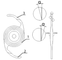
理解を助けるために、図1を参照し、本発明によって提供される全視程眼内レンズの一実施例は、光学部1と、第1支持部2と、第2支持部3とを含み、光学部1、及び第1支持部2、第2支持部3は、同じ素材で一体成形される一体式の構造であり、光学部1は2つの光学面(光学面A、光学面B)からなり、前記光学面は球面又は非球面であり、そのうち、光学面Aは入射光の光場分布を変調するための回折構造を有する。
Example 2
Specifically, based on Example 1, a specific example will be used to explain the technical solution, so as to better express the effect of the technical solution.
For ease of understanding, refer to FIG. 1. One embodiment of the full-vision intraocular lens provided by the present invention includes an
回折構造は、旋盤加工により、光学部1の一方の光学表面に浮き出し加工され、ここで回折構造を光学面Aに重ねるものとし、第1支持部2、第2支持部3の表面にいずれも斜め鋸歯状の凹部が設けられ、斜め鋸歯の高さは40μmより大きく、斜め鋸歯状の凹部の幅は0.2mmであり、前記支持部の位置する平面に対して斜め鋸歯の斜め縁部のなす角の角度αは20°である。支持部は、第1支持部2と、第2支持部3とを含む。
The diffractive structure is embossed on one optical surface of the
光学部1は、有効光学部径が6.0mmで、中心厚が0.67mmである両凸レンズであり、前記第1支持部2、第2支持部3の厚さはいずれも0.15mmであり、光学部1は、屈折率が1.544で、分散係数が45~55である疎水性ポリアクリレートから作製される。
The
本実施例の全視程眼内レンズの製造方法は以下のとおりである。
(1)全体的な設計であって、遠方焦点20D、中間焦点2D、近方焦点3Dの3焦点眼内レンズを設計し、中間焦点と近方焦点を連続させる。
The manufacturing method of the full visibility intraocular lens of this embodiment is as follows.
(1) Overall design: A trifocal intraocular lens is designed with a far focus 20D, an intermediate focus 2D, and a near focus 3D, with the intermediate and near focuses being continuous.
(2)光学設計であって、予め設定された多焦点の各焦点距離、即ち、50mm(20D)、45.45mm(22D)、43.48mm(23D)により、固定焦点領域及び連続領域を分割し、ここで、固定焦点領域が2つで、連続領域が1つである。固定焦点領域は総面積の70%で、連続領域は総面積の30%である。Zemaxにおいて初期モデルを構築し、最適化して光学部1の光学面A、光学面Bのパラメータを得て、ここで、ベース半径は20.5mmで、K=-11.68である。位相係数に基づいて2つの固定焦点領域の位相関数を決定する。
Φ1(x,y)=-101.13x2-0.986x4
Φ2(x,y)=-151.7x2-1.48x4
所定の2つの連続した焦点22D及び23Dにより、連続領域に均一に分布する5つの離散回折位相点を追加すると決め、その大きさはΦ1とΦ2の中間値である。
(2) Optical design, the fixed focal area and the continuous area are divided by the preset multifocal focal lengths, i.e., 50mm (20D), 45.45mm (22D), 43.48mm (23D), where there are two fixed focal areas and one continuous area. The fixed focal area is 70% of the total area, and the continuous area is 30% of the total area. An initial model is constructed in Zemax, and the parameters of the optical surface A and the optical surface B of the
Φ 1 (x,y)=-101.13x 2 -0.986x 4
Φ 2 (x, y) = -151.7x 2 -1.48x 4
Given two consecutive focal points 22D and 23D, we decide to add five discrete diffractive phase points uniformly distributed in a continuous area, whose magnitude is intermediate between Φ 1 and Φ 2 .
(3)ベース屈折レンズの旋盤加工であって、設計した光学領域のパラメータに従って、旋盤プログラムを作成し、ダイヤモンドによる一点切削技術を用いて、旋盤加工により眼内レンズの雛型を得て、フライス盤プログラムを作成して、フライス加工により光学領域の形状及び粗化表面を有するレッグを得る。 (3) A lathe machining of a base refractive lens, in which a lathe program is created according to the parameters of the designed optical region, a diamond single-point cutting technique is used to obtain a template for the intraocular lens by lathe machining, a milling program is created, and a leg having the shape of the optical region and a roughened surface is obtained by milling.
(4)研磨処理により、光学表面が基準を満たす眼内レンズを得る。 (4) Through polishing, an intraocular lens whose optical surface meets the standards is obtained.
(5)眼モデルにおいて分析・テストする。 (5) Analyze and test in an eye model.
実施例1の全視程眼内レンズIOLをISO11979-2で規定されている眼モデルに導入し、光学機器でテストして22Dと23Dとの間の0.2DごとのUSAF1951解像度テストチャートによるテストの結果を得る。図3から分かるように、当該全視程眼内レンズIOLは22Dと23Dとの間にいずれも明瞭な視覚効果が得られる。図中、aは22D、bは22.2D、cは22.4D、dは22.6D、eは22.8D、fは23Dである。 The full-range intraocular lens IOL of Example 1 is introduced into the eye model specified in ISO11979-2, and tested with an optical instrument to obtain the test results by the USAF1951 resolution test chart at every 0.2D between 22D and 23D. As can be seen from Figure 3 , the full-range intraocular lens IOL can obtain clear visual effects between 22D and 23D. In the figure, a is 22D, b is 22.2D, c is 22.4D, d is 22.6D, e is 22.8D, and f is 23D.
従来技術による全視程眼内レンズIOLには、視程が不足し、複数の焦点の間に明らかな視力低下ひいては中断点が発生してしまい、視力低下又は中断点が視程の不連続性を引き起こすため、患者の移動物体に対する識別能力が低下するという欠点が存在する問題に対し、本発明は、離散回折位相点を導入して、入射光の光場分布を変調することにより、2つ又はそれ以上の焦点を連続させ、模擬眼モデルでMTF値を測定したところ連続範囲においてはいずれも0.13より大きく、患者に0.6以上の連続した明瞭な視力を提供することができ、点視力から連続した視力への飛躍を実現し、患者の動体視力を向上させ、運動する物体を明瞭に結像でき、患者の生活の質を向上させるとともに、グレアを低減させ、色収差を軽減し、光エネルギーの利用率を向上させる効果がある。 In the prior art, the full-visibility intraocular lens IOL has the disadvantage that the visibility is insufficient, and obvious visual impairment and even interruptions occur between multiple foci, and the visual impairment or interruptions cause discontinuity in visibility, reducing the patient's ability to distinguish moving objects. In response to this problem, the present invention introduces discrete diffractive phase points to modulate the optical field distribution of the incident light, thereby making two or more foci continuous, and when the MTF values were measured using a simulated eye model, all were greater than 0.13 in the continuous range, providing the patient with clear, continuous visual acuity of 0.6 or more, realizing a leap from point visual acuity to continuous visual acuity, improving the patient's dynamic visual acuity, allowing the image of moving objects to be clearly formed, improving the quality of life of the patient, while also reducing glare, reducing chromatic aberration, and improving the utilization rate of light energy.
なお、本発明は、光学部1の光学領域が2焦点、3焦点、又は領域に多焦点がある光学領域である。3焦点IOLでは、中間視力から近方視力までの範囲で視程の不連続性が比較的明らかであるという問題に対し、本発明は良い改善効果を有する。
In the present invention, the optical zone of the
(実施例3)
具体的には、実施例1を踏まえ、具体的な実施例を用いて技術的解決手段を説明して、当該技術的解決手段の効果を一層表現する。具体的には、以下のとおりである。
全視程眼内レンズであって、前記眼内レンズは、光学部1と、第1支持部2と、第2支持部3とを含み、光学部1は、光学面Aと、光学面Bと、回折構造とからなり、回折構造は光学面Aにある。光学部1、及び第1支持部2、第2支持部3は、同じ素材で一体成形される一体式の構造であり、回折構造は、旋盤加工により、光学部1の一方の光学表面に浮き出し加工され、ここで回折構造を光学面Aに重ねるものとする。
Example 3
Specifically, based on Example 1, a specific example will be used to explain the technical solution, so as to better express the effect of the technical solution.
The full-visibility intraocular lens includes an
第1支持部2、第2支持部3の表面にいずれもいくつかの斜め鋸歯状の凹部が設けられ、且つ斜め鋸歯状の凹部の幅は0.2mmであり、支持部の位置する平面に対して斜め鋸歯の斜め縁部のなす角の角度αは20°であり、斜め鋸歯の高さは40μmより大きい。
The surfaces of both the
光学部1は、有効光学部径が5.5mmで、中心厚が0.6mmである両凸レンズであり、第1支持部2、第2支持部3の厚さはいずれも0.15mmであり、光学部1は、屈折率が1.544で、分散係数が45~55である疎水性ポリアクリレートから作製される。
The
本実施例の全視程眼内レンズの製造方法は以下のとおりである。
(1)全体的な設計であって、遠方焦点15D、中間焦点2D、近方焦点4Dの3焦点眼内レンズを設計し、中間焦点と近方焦点を連続させる。
The manufacturing method of the full visibility intraocular lens of this embodiment is as follows.
(1) Overall design: A trifocal intraocular lens is designed with a far focus of 15D, an intermediate focus of 2D, and a near focus of 4D, with the intermediate and near focuses being continuous.
(2)光学設計であって、予め設定された多焦点の各焦点距離、即ち、66.67mm(15D)、58.82mm(17D)、52.63mm(19D)により、固定焦点領域及び連続領域を分割し、ここで、固定焦点領域が2つで、連続領域が1つである。固定焦点領域は総面積の50%で、連続領域は総面積の50%である。Zemaxにおいて初期モデルを構築し、最適化して光学部1の光学面A、光学面Bのパラメータを得て、ここで、ベース半径は31.57mmで、K=-19.74である。位相係数に基づいて2つの固定焦点領域の位相関数を決定する。
Φ1(x,y)=-101.2x2+0.72x4
Φ2(x,y)=-202.22x2-1.424x4
所定の2つの連続した焦点17D及び19Dにより、連続領域に均一に分布する10の離散回折位相点を追加すると決め、その大きさはΦ1とΦ2の中間値である。
(2) Optical design, the fixed focal area and the continuous area are divided by the preset multifocal focal lengths, i.e., 66.67mm (15D), 58.82mm (17D), 52.63mm (19D), where there are two fixed focal areas and one continuous area. The fixed focal area is 50% of the total area, and the continuous area is 50% of the total area. An initial model is constructed in Zemax, and the parameters of the optical surface A and the optical surface B of the
Φ 1 (x,y)=-101.2x 2 +0.72x 4
Φ 2 (x, y) = -202.22x 2 -1.424x 4
Given two consecutive focal points 17D and 19D, we decide to add 10 discrete diffractive phase points uniformly distributed in a continuous area, whose size is intermediate between Φ 1 and Φ 2 .
(3)ベース屈折レンズの旋盤加工であって、設計した光学領域のパラメータに従って、旋盤プログラムを作成し、ダイヤモンドによる一点切削技術を用いて、旋盤加工により眼内レンズの雛型を得て、フライス盤プログラムを作成して、フライス加工により光学領域の形状及び粗化表面を有するレッグを得る。 (3) A lathe machining of a base refractive lens, in which a lathe program is created according to the parameters of the designed optical region, a diamond single-point cutting technique is used to obtain a template for the intraocular lens by lathe machining, a milling program is created, and a leg having the shape of the optical region and a roughened surface is obtained by milling.
(4)研磨処理により、光学表面が基準を満たす眼内レンズを得る。 (4) Through polishing, an intraocular lens whose optical surface meets the standards is obtained.
(5)眼モデルにおいて分析・テストする。 (5) Analyze and test in an eye model.
本実施例の眼内レンズIOLをISO11979-2で規定されている眼モデルに導入し、光学機器でテストして中間焦点(17D)と近方焦点(19D)との間の0.2DごとのUSAF1951解像度テストチャートによるテストの結果を得る。図4から分かるように、当該全視程眼内レンズIOLは17Dと19Dとの間にいずれも明瞭な視覚効果が得られる。図中、aは17D、bは17.2D、cは17.4D、dは17.6D、eは17.8D、fは18D、gは18.2D、hは18.4D、iは18.6D、jは18.8D、kは19Dである。 The intraocular lens IOL of this embodiment is introduced into the eye model specified by ISO11979-2, and tested with an optical instrument to obtain the test results by the USAF1951 resolution test chart every 0.2D between the intermediate focus (17D) and the near focus (19D). As can be seen from Figure 4 , the full-visibility intraocular lens IOL can obtain clear visual effects between 17D and 19D. In the figure, a is 17D, b is 17.2D, c is 17.4D, d is 17.6D, e is 17.8D, f is 18D, g is 18.2D, h is 18.4D, i is 18.6D, j is 18.8D, and k is 19D.
(実施例4)
具体的には、実施例1を踏まえ、具体的な実施例を用いて技術的解決手段を説明して、当該技術的解決手段の効果を一層表現する。具体的には、以下のとおりである。
図2に示すように、全視程眼内レンズであって、眼内レンズは、光学部1と、第1支持部2と、第2支持部3とを含み、光学部1は、光学面Aと、光学面Bと、回折構造とからなり、回折構造は光学面Aにある。
Example 4
Specifically, based on Example 1, a specific example will be used to explain the technical solution, so as to better express the effect of the technical solution.
As shown in FIG. 2 , the full-visibility intraocular lens includes an
光学部1、及び第1支持部2、第2支持部3は、同じ素材で一体成形される一体式の構造であり、回折構造は、旋盤加工により、光学部1の一方の光学表面に浮き出し加工され、ここで回折構造を光学面Aに重ねるものとする。
第1支持部2、第2支持部3の表面にいずれもいくつかの斜め鋸歯状の凹部が設けられ、斜め鋸歯の高さは40μmより大きく、斜め鋸歯状の凹部の幅は0.2mmであり、支持部の位置する平面に対して斜め鋸歯の斜め縁部のなす角の角度αは20°である。
The
Both the
光学部1は、有効光学部径が5.5mmで、中心厚が0.78mmである両凸レンズであり、第1支持部2、第2支持部3の厚さはいずれも0.15mmであり、光学部1は、屈折率が1.544で、分散係数が45~55である疎水性ポリアクリレートから作製される。
The
本実施例の全視程眼内レンズの製造方法は以下のとおりである。
(1)全体的な設計であって、遠方焦点28D、中間焦点2.5D、近方焦点4Dの3焦点眼内レンズを設計し、中間焦点と近方焦点を連続させる。
The manufacturing method of the full visibility intraocular lens of this embodiment is as follows.
(1) Overall design: A trifocal intraocular lens is designed with a far focus of 28D, an intermediate focus of 2.5D, and a near focus of 4D, with the intermediate and near focuses being continuous.
(2)光学設計であって、予め設定された多焦点の各焦点距離、即ち、35.71mm(28D)、32.79mm(30.5D)、31.25mm(32D)により、固定焦点領域及び連続領域を分割し、ここで、固定焦点領域が2つで、連続領域が1つである。固定焦点領域は総面積の60%で、連続領域は総面積の40%である。Zemaxにおいて初期モデルを構築し、最適化して光学部1の光学面A、光学面Bのパラメータを得て、ここで、ベース半径は15.75mmで、K=-8.14である。位相係数に基づいて2つの固定焦点領域の位相関数を決定する。
Φ1(x,y)=-128.746x2+0.096x4
Φ2(x,y)=-206.925x2+0.709x4
所定の2つの連続した焦点30.5D及び33Dにより、連続領域に均一に分布する8つの離散回折位相点を追加すると決め、その大きさはΦ1とΦ2の中間値である。
(2) Optical design, the fixed focal area and the continuous area are divided by the preset multifocal focal lengths, i.e., 35.71 mm (28D), 32.79 mm (30.5D), and 31.25 mm (32D), where there are two fixed focal areas and one continuous area. The fixed focal area is 60% of the total area, and the continuous area is 40% of the total area. An initial model is constructed in Zemax, and the parameters of the optical surface A and the optical surface B of the
Φ 1 (x, y) = -128.746x 2 +0.096x 4
Φ 2 (x, y) = -206.925x 2 +0.709x 4
Given two consecutive focal points 30.5D and 33D, we decide to add eight discrete diffractive phase points uniformly distributed in a continuous area, whose size is intermediate between Φ 1 and Φ 2 .
(3)ベース屈折レンズの旋盤加工であって、設計した光学領域のパラメータに従って、旋盤プログラムを作成し、ダイヤモンドによる一点切削技術を用いて、旋盤加工により眼内レンズの雛型を得て、フライス盤プログラムを作成して、フライス加工により光学領域の形状及び粗化表面を有するレッグを得る。 (3) A lathe machining of a base refractive lens, in which a lathe program is created according to the parameters of the designed optical region, a diamond single-point cutting technique is used to obtain a template for the intraocular lens by lathe machining, a milling program is created, and a leg having the shape of the optical region and a roughened surface is obtained by milling.
(4)研磨処理により、光学表面が基準を満たす眼内レンズを得る。 (4) Through polishing, an intraocular lens whose optical surface meets the standards is obtained.
(5)眼モデルにおいて分析・テストする。 (5) Analyze and test in an eye model.
本実施例の眼内レンズIOLをISO11979-2で規定されている眼モデルに導入し、光学機器でテストして中間焦点(30.5D)と近方焦点(32D)との間の0.2DごとのUSAF1951解像度テストチャートによるテストの結果を得る。図5から分かるように、30.5Dと32Dとの間にいずれも明瞭な視覚効果が得られる。図中、aは30.5D、bは30.6D、cは30.8D、dは31D、eは31.2D、fは31.4D、gは31.6D、hは31.8D、iは32Dである。 The intraocular lens IOL of this embodiment is introduced into an eye model specified by ISO11979-2, and tested with an optical instrument to obtain the test results by the USAF1951 resolution test chart every 0.2D between the intermediate focus (30.5D) and the near focus (32D). As can be seen from Figure 5 , a clear visual effect is obtained between 30.5D and 32D. In the figure, a is 30.5D, b is 30.6D, c is 30.8D, d is 31D, e is 31.2D, f is 31.4D, g is 31.6D, h is 31.8D, and i is 32D.
なお、上記の実施例は、3焦点眼内レンズを例として本発明の実施の効果を説明しているが、回折型多焦点眼内レンズの視程の不連続性の問題に対する本発明の解決方法は、他の回折型多焦点眼内レンズにも適用する。 Note that the above examples explain the effects of implementing the present invention using a trifocal intraocular lens as an example, but the solution of the present invention to the problem of discontinuity in visibility in diffractive multifocal intraocular lenses can also be applied to other diffractive multifocal intraocular lenses.
言うまでもないが、本発明の上記の実施例は本発明を明瞭に説明するために挙げた例に過ぎず、本発明の実施形態についての限定ではない。当業者であれば、上記の説明に基づいて他に様々な形態の変更又は補正を行うことができる。ここでは全ての実施形態を列挙する必要もないしそうすることもできない。本発明の趣旨と原則を逸脱することなく補正、同等な置き換え、改善などを行った場合、そのいずれも本発明の特許請求に係る保護範囲のうちに含まれるものとする。 Needless to say, the above examples of the present invention are merely examples given to clearly explain the present invention, and are not intended to limit the embodiments of the present invention. Those skilled in the art may make various other modifications or amendments based on the above description. It is not necessary or possible to list all the embodiments here. Any amendments, equivalent replacements, improvements, etc. made without departing from the spirit and principles of the present invention shall be included within the scope of protection of the claims of the present invention.
Claims (10)
前記光学部(1)は2つの光学面からなり、前記光学面は球面又は非球面であり、一方の光学面は入射光の光場分布を変調するための回折構造を有し、
前記光学部(1)の上光学面の決定方法は以下のとおりであって、
光学面の頂点を原点O、光軸をZ軸として、任意の空間上の直交座標系を確立し、前記座標系のX軸及びY軸が前記光学面に相接し、前記光学面の面形状はYZ平面において以下の方程式を満たし、
式中、Z(y)は2次元座標系のYZ平面における光学面の曲線表現式であり、cは前記光学面の基本球面の曲率半径の逆数であり、yはZ軸に対する前記曲線上のいずれかの点の垂直距離であり、A2iは光学面の高次項の係数であり、m、nはいずれも1以上の整数で且つn>mであり、Kは光学面係数であり、K及びA2iが0であるとき、Z(y)は球面の方程式になり、
回折構造により入射光の光場分布を変調する方法は以下のとおりであって、
回折構造は回折環帯構造及び離散回折位相点を含み、まず、回折環帯構造を利用して固定焦点を決定し、つまり、回折環帯構造を備える単焦点回折素子に対して、回折位相関数Φでその位相を示し、
Φ(x,y)=ρ1x2+ρ2x4(2)
式中、x、yはそれぞれ縦座標、横座標を表し、単位はミリメートル(mm)であり、ρ1、ρ2は回折位相の各項の係数であり、回折位相関数を周期2πで圧縮した後、回折環帯構造の位相関数T(Φ)を得て、
T(Φ)=Φ-int(Φ/2π)×2π(3)
式中、int()は整数に丸める関数を表し、
次に、サブ波長領域の離散回折位相点を導入し、フェルマーの原理によれば、光の伝播経路は光路長が極値をとる経路であり、この極値は最大値、最小値であるか、又は関数の変曲点であり、式で示すと以下のとおりであって、


The optical unit (1) is composed of two optical surfaces, the optical surfaces being spherical or aspherical, one of the optical surfaces having a diffractive structure for modulating the optical field distribution of incident light;
A method for determining the upper optical surface of the optical portion (1) is as follows:
A Cartesian coordinate system is established in an arbitrary space with the vertex of the optical surface as the origin O and the optical axis as the Z axis, the X-axis and the Y-axis of the coordinate system are tangent to the optical surface, and the surface shape of the optical surface satisfies the following equation in the YZ plane:
In the formula, Z(y) is a curve expression formula of an optical surface in the YZ plane of a two-dimensional coordinate system, c is the inverse of the radius of curvature of a base sphere of said optical surface, y is the perpendicular distance of any point on said curve with respect to the Z axis, A2i is a coefficient of a high-order term of the optical surface, m and n are both integers of 1 or more and n>m, K is an optical surface coefficient, and when K and A2i are 0, Z(y) becomes an equation of a spherical surface,
A method for modulating the optical field distribution of incident light by a diffractive structure is as follows:
The diffractive structure includes a diffractive ring structure and a discrete diffractive phase point. First, the diffractive ring structure is used to determine a fixed focus. That is, for a single focus diffractive element having a diffractive ring structure, its phase is represented by a diffractive phase function Φ;
Φ(x,y)=ρ 1 x 2 +ρ 2 x 4 (2)
In the formula, x and y are the ordinate and abscissa, respectively, in millimeters (mm), and ρ 1 and ρ 2 are the coefficients of each term of the diffraction phase. After compressing the diffraction phase function with a period of 2π, the phase function T(Φ) of the diffraction annulus structure is obtained,
T(Φ)=Φ-int(Φ/2π)×2π(3)
In the formula, int() represents the integer rounding function,
Next, discrete diffraction phase points in the sub-wavelength region are introduced. According to Fermat's principle, the propagation path of light is a path where the optical path length has an extreme value, and this extreme value is a maximum value, a minimum value, or an inflection point of a function, which can be expressed by the following formula:
Applications Claiming Priority (3)
| Application Number | Priority Date | Filing Date | Title |
|---|---|---|---|
| CN202211470181.5A CN115721448B (en) | 2022-11-22 | 2022-11-22 | Full vision range type artificial lens |
| CN202211470181.5 | 2022-11-22 | ||
| PCT/CN2023/132377 WO2024109658A1 (en) | 2022-11-22 | 2023-11-17 | Full-visual-range intraocular lens |
Publications (2)
| Publication Number | Publication Date |
|---|---|
| JP2024545527A JP2024545527A (en) | 2024-12-09 |
| JP7686890B2 true JP7686890B2 (en) | 2025-06-02 |
Family
ID=85297641
Family Applications (1)
| Application Number | Title | Priority Date | Filing Date |
|---|---|---|---|
| JP2024538269A Active JP7686890B2 (en) | 2022-11-22 | 2023-11-17 | Full Visibility Intraocular Lens |
Country Status (7)
| Country | Link |
|---|---|
| US (1) | US20240335277A1 (en) |
| EP (1) | EP4431058A4 (en) |
| JP (1) | JP7686890B2 (en) |
| KR (1) | KR20240113509A (en) |
| CN (1) | CN115721448B (en) |
| AU (1) | AU2023384477B2 (en) |
| WO (1) | WO2024109658A1 (en) |
Families Citing this family (2)
| Publication number | Priority date | Publication date | Assignee | Title |
|---|---|---|---|---|
| CN115721448B (en) * | 2022-11-22 | 2023-10-31 | 无锡蕾明视康科技有限公司 | Full vision range type artificial lens |
| CN119126408B (en) * | 2024-11-14 | 2025-03-28 | 上海晶伟尔医疗科技有限公司 | A large optical zone intraocular lens based on edge phase technology |
Citations (3)
| Publication number | Priority date | Publication date | Assignee | Title |
|---|---|---|---|---|
| CN108938144A (en) | 2018-06-07 | 2018-12-07 | 无锡蕾明视康科技有限公司 | A kind of diffractive multifocal intraocular lens of smooth position phase |
| JP2020528167A (en) | 2017-07-26 | 2020-09-17 | ヴェセイェ・ビヨテクノロジ・ヴェ・イラチ・サナイ・アノニム・シルケティVsy Biyoteknoloji Ve Ilac Sanayi Anonim Sirketi | Ophthalmic multifocal diffractive lens |
| CN115024859A (en) | 2022-05-31 | 2022-09-09 | 南开大学 | Multifocal intraocular lens with smooth phase distribution |
Family Cites Families (10)
| Publication number | Priority date | Publication date | Assignee | Title |
|---|---|---|---|---|
| US7481532B2 (en) * | 2006-02-09 | 2009-01-27 | Alcon, Inc. | Pseudo-accommodative IOL having multiple diffractive patterns |
| WO2016021627A1 (en) * | 2014-08-08 | 2016-02-11 | 株式会社メニコン | Method for producing diffractive multifocal ophthalmic lens and diffractive multifocal ophthalmic lens |
| CN110062899B (en) * | 2016-11-29 | 2021-05-28 | 爱尔康公司 | Intraocular lens with zone-by-zone step height control |
| CN107212949B (en) * | 2017-07-12 | 2019-05-14 | 无锡蕾明视康科技有限公司 | A kind of multifocal intraocular lenses |
| WO2019198027A1 (en) * | 2018-04-12 | 2019-10-17 | Alcon Inc. | Full depth of focus intraocular lens |
| CN108814770B (en) * | 2018-04-24 | 2020-09-01 | 南开大学 | A dual-region aspheric diffractive intraocular lens with extended depth of field performance |
| EP3939543A1 (en) * | 2020-07-15 | 2022-01-19 | Hoya Corporation | Multifocal lens |
| CN116867464A (en) * | 2021-02-21 | 2023-10-10 | Rx视觉股份有限公司 | Composite optically adjustable intraocular lens with diffraction structure |
| CN113693779B (en) * | 2021-06-01 | 2023-03-14 | 天津世纪康泰生物医学工程有限公司 | Diffraction type multifocal intraocular lens with targeted light field distribution |
| CN115721448B (en) * | 2022-11-22 | 2023-10-31 | 无锡蕾明视康科技有限公司 | Full vision range type artificial lens |
-
2022
- 2022-11-22 CN CN202211470181.5A patent/CN115721448B/en active Active
-
2023
- 2023-11-17 WO PCT/CN2023/132377 patent/WO2024109658A1/en not_active Ceased
- 2023-11-17 JP JP2024538269A patent/JP7686890B2/en active Active
- 2023-11-17 KR KR1020247020086A patent/KR20240113509A/en active Pending
- 2023-11-17 EP EP23893748.6A patent/EP4431058A4/en active Pending
- 2023-11-17 AU AU2023384477A patent/AU2023384477B2/en active Active
-
2024
- 2024-06-18 US US18/746,048 patent/US20240335277A1/en active Pending
Patent Citations (3)
| Publication number | Priority date | Publication date | Assignee | Title |
|---|---|---|---|---|
| JP2020528167A (en) | 2017-07-26 | 2020-09-17 | ヴェセイェ・ビヨテクノロジ・ヴェ・イラチ・サナイ・アノニム・シルケティVsy Biyoteknoloji Ve Ilac Sanayi Anonim Sirketi | Ophthalmic multifocal diffractive lens |
| CN108938144A (en) | 2018-06-07 | 2018-12-07 | 无锡蕾明视康科技有限公司 | A kind of diffractive multifocal intraocular lens of smooth position phase |
| CN115024859A (en) | 2022-05-31 | 2022-09-09 | 南开大学 | Multifocal intraocular lens with smooth phase distribution |
Also Published As
| Publication number | Publication date |
|---|---|
| CN115721448B (en) | 2023-10-31 |
| JP2024545527A (en) | 2024-12-09 |
| EP4431058A4 (en) | 2025-06-18 |
| AU2023384477A1 (en) | 2024-07-04 |
| US20240335277A1 (en) | 2024-10-10 |
| CN115721448A (en) | 2023-03-03 |
| WO2024109658A1 (en) | 2024-05-30 |
| EP4431058A1 (en) | 2024-09-18 |
| AU2023384477B2 (en) | 2025-05-15 |
| KR20240113509A (en) | 2024-07-22 |
Similar Documents
| Publication | Publication Date | Title |
|---|---|---|
| KR101309604B1 (en) | Pseudo-accomodative iol having diffractive zones with varying areas | |
| JP4551489B2 (en) | Manufacturing method of diffractive lens | |
| JP7686890B2 (en) | Full Visibility Intraocular Lens | |
| AU2005311949B2 (en) | Apodized aspheric diffractive lenses | |
| EP1982230B1 (en) | Pseudo-accomodative iol having multiple diffractive patterns | |
| KR101339715B1 (en) | Zonal difractive multifocal intraocular lenses | |
| CN108938144B (en) | Phase-smoothing diffractive multifocal intraocular lens | |
| JP2019523023A (en) | Multifocal intraocular lens | |
| JP2019534071A (en) | Intraocular lens with extended depth of focus | |
| WO1994011765A1 (en) | Diffractive trifocal intraocular lens design | |
| KR20050062426A (en) | Multifocal contact lenses having a pinhole | |
| KR20230156366A (en) | Intraocular lenses provide extended depth of focus | |
| CN115867229A (en) | Ophthalmic lens | |
| CN121196799A (en) | A depth-of-focus intraocular lens based on a sinusoidal grating |
Legal Events
| Date | Code | Title | Description |
|---|---|---|---|
| A521 | Request for written amendment filed |
Free format text: JAPANESE INTERMEDIATE CODE: A523 Effective date: 20240620 |
|
| A621 | Written request for application examination |
Free format text: JAPANESE INTERMEDIATE CODE: A621 Effective date: 20240621 |
|
| A521 | Request for written amendment filed |
Free format text: JAPANESE INTERMEDIATE CODE: A523 Effective date: 20241120 |
|
| A977 | Report on retrieval |
Free format text: JAPANESE INTERMEDIATE CODE: A971007 Effective date: 20250421 |
|
| TRDD | Decision of grant or rejection written | ||
| A01 | Written decision to grant a patent or to grant a registration (utility model) |
Free format text: JAPANESE INTERMEDIATE CODE: A01 Effective date: 20250507 |
|
| A61 | First payment of annual fees (during grant procedure) |
Free format text: JAPANESE INTERMEDIATE CODE: A61 Effective date: 20250521 |
|
| R150 | Certificate of patent or registration of utility model |
Ref document number: 7686890 Country of ref document: JP Free format text: JAPANESE INTERMEDIATE CODE: R150 |