JP7686887B2 - Reaction plate with odd number of tabs on drive and coast - Google Patents
Reaction plate with odd number of tabs on drive and coast Download PDFInfo
- Publication number
- JP7686887B2 JP7686887B2 JP2024531193A JP2024531193A JP7686887B2 JP 7686887 B2 JP7686887 B2 JP 7686887B2 JP 2024531193 A JP2024531193 A JP 2024531193A JP 2024531193 A JP2024531193 A JP 2024531193A JP 7686887 B2 JP7686887 B2 JP 7686887B2
- Authority
- JP
- Japan
- Prior art keywords
- torque
- tabs
- torque transmission
- coupling windows
- reaction plate
- Prior art date
- Legal status (The legal status is an assumption and is not a legal conclusion. Google has not performed a legal analysis and makes no representation as to the accuracy of the status listed.)
- Active
Links
Images


Classifications
-
- F—MECHANICAL ENGINEERING; LIGHTING; HEATING; WEAPONS; BLASTING
- F16—ENGINEERING ELEMENTS AND UNITS; GENERAL MEASURES FOR PRODUCING AND MAINTAINING EFFECTIVE FUNCTIONING OF MACHINES OR INSTALLATIONS; THERMAL INSULATION IN GENERAL
- F16H—GEARING
- F16H45/00—Combinations of fluid gearings for conveying rotary motion with couplings or clutches
- F16H45/02—Combinations of fluid gearings for conveying rotary motion with couplings or clutches with mechanical clutches for bridging a fluid gearing of the hydrokinetic type
-
- F—MECHANICAL ENGINEERING; LIGHTING; HEATING; WEAPONS; BLASTING
- F16—ENGINEERING ELEMENTS AND UNITS; GENERAL MEASURES FOR PRODUCING AND MAINTAINING EFFECTIVE FUNCTIONING OF MACHINES OR INSTALLATIONS; THERMAL INSULATION IN GENERAL
- F16H—GEARING
- F16H45/00—Combinations of fluid gearings for conveying rotary motion with couplings or clutches
-
- F—MECHANICAL ENGINEERING; LIGHTING; HEATING; WEAPONS; BLASTING
- F16—ENGINEERING ELEMENTS AND UNITS; GENERAL MEASURES FOR PRODUCING AND MAINTAINING EFFECTIVE FUNCTIONING OF MACHINES OR INSTALLATIONS; THERMAL INSULATION IN GENERAL
- F16D—COUPLINGS FOR TRANSMITTING ROTATION; CLUTCHES; BRAKES
- F16D13/00—Friction clutches
- F16D13/22—Friction clutches with axially-movable clutching members
- F16D13/38—Friction clutches with axially-movable clutching members with flat clutching surfaces, e.g. discs
- F16D13/385—Friction clutches with axially-movable clutching members with flat clutching surfaces, e.g. discs double clutches, i.e. comprising two friction disc mounted on one driven shaft
-
- F—MECHANICAL ENGINEERING; LIGHTING; HEATING; WEAPONS; BLASTING
- F16—ENGINEERING ELEMENTS AND UNITS; GENERAL MEASURES FOR PRODUCING AND MAINTAINING EFFECTIVE FUNCTIONING OF MACHINES OR INSTALLATIONS; THERMAL INSULATION IN GENERAL
- F16D—COUPLINGS FOR TRANSMITTING ROTATION; CLUTCHES; BRAKES
- F16D13/00—Friction clutches
- F16D13/58—Details
- F16D13/60—Clutching elements
- F16D13/64—Clutch-plates; Clutch-lamellae
- F16D13/68—Attachments of plates or lamellae to their supports
-
- F—MECHANICAL ENGINEERING; LIGHTING; HEATING; WEAPONS; BLASTING
- F16—ENGINEERING ELEMENTS AND UNITS; GENERAL MEASURES FOR PRODUCING AND MAINTAINING EFFECTIVE FUNCTIONING OF MACHINES OR INSTALLATIONS; THERMAL INSULATION IN GENERAL
- F16D—COUPLINGS FOR TRANSMITTING ROTATION; CLUTCHES; BRAKES
- F16D13/00—Friction clutches
- F16D13/58—Details
- F16D13/70—Pressure members, e.g. pressure plates, for clutch-plates or lamellae; Guiding arrangements for pressure members
-
- F—MECHANICAL ENGINEERING; LIGHTING; HEATING; WEAPONS; BLASTING
- F16—ENGINEERING ELEMENTS AND UNITS; GENERAL MEASURES FOR PRODUCING AND MAINTAINING EFFECTIVE FUNCTIONING OF MACHINES OR INSTALLATIONS; THERMAL INSULATION IN GENERAL
- F16H—GEARING
- F16H41/00—Rotary fluid gearing of the hydrokinetic type
- F16H41/24—Details
-
- F—MECHANICAL ENGINEERING; LIGHTING; HEATING; WEAPONS; BLASTING
- F16—ENGINEERING ELEMENTS AND UNITS; GENERAL MEASURES FOR PRODUCING AND MAINTAINING EFFECTIVE FUNCTIONING OF MACHINES OR INSTALLATIONS; THERMAL INSULATION IN GENERAL
- F16H—GEARING
- F16H45/00—Combinations of fluid gearings for conveying rotary motion with couplings or clutches
- F16H2045/002—Combinations of fluid gearings for conveying rotary motion with couplings or clutches comprising a clutch between prime mover and fluid gearing
-
- F—MECHANICAL ENGINEERING; LIGHTING; HEATING; WEAPONS; BLASTING
- F16—ENGINEERING ELEMENTS AND UNITS; GENERAL MEASURES FOR PRODUCING AND MAINTAINING EFFECTIVE FUNCTIONING OF MACHINES OR INSTALLATIONS; THERMAL INSULATION IN GENERAL
- F16H—GEARING
- F16H45/00—Combinations of fluid gearings for conveying rotary motion with couplings or clutches
- F16H45/02—Combinations of fluid gearings for conveying rotary motion with couplings or clutches with mechanical clutches for bridging a fluid gearing of the hydrokinetic type
- F16H2045/0273—Combinations of fluid gearings for conveying rotary motion with couplings or clutches with mechanical clutches for bridging a fluid gearing of the hydrokinetic type characterised by the type of the friction surface of the lock-up clutch
- F16H2045/0284—Multiple disk type lock-up clutch
Landscapes
- Engineering & Computer Science (AREA)
- General Engineering & Computer Science (AREA)
- Mechanical Engineering (AREA)
- Hydraulic Clutches, Magnetic Clutches, Fluid Clutches, And Fluid Joints (AREA)
- Transmissions By Endless Flexible Members (AREA)
- Automotive Seat Belt Assembly (AREA)
Description
関連出願の相互参照
この出願は、2022年1月11日に出願された米国非仮出願第17/573,428号に対する優先権を主張するものであり、その開示全体は、参照により本明細書に組み込まれる。
CROSS-REFERENCE TO RELATED APPLICATIONS This application claims priority to U.S. Non-provisional Application No. 17/573,428, filed January 11, 2022, the entire disclosure of which is incorporated herein by reference.
技術分野
本開示は、自動変速機における動力伝達装置に関する。より詳細には、本開示は、トルクコンバータにおいてトルクの転移に関する。
TECHNICAL FIELD This disclosure relates to power transmission devices in automatic transmissions, and more particularly to torque transfer in torque converters.
従来、トルクコンバータにおいて、ピストンは、リアクションプレート内のトルク伝達歯を介して外側クラッチプレートの複数のトルク伝達タブに結合された複数のトルク伝達タブを有する。典型的には、トルク伝達タブの各ペア(ピストン及び外側クラッチプレートから1つずつ)が、リアクションプレートの外側周辺部のウェビングに刻印された結合窓内で一緒に結合される。各窓は、2つのトルク伝達歯、すなわち、結合窓の各端部の近くに1つを備える。2つのトルク伝達歯のうちの一方は、駆動方向に駆動トルクを伝達し、トルク伝達歯のうちのもう一方は、コースト方向(駆動方向とは反対)にトルクを駆動する。 Traditionally, in a torque converter, a piston has multiple torque transfer tabs that are coupled to multiple torque transfer tabs on an outer clutch plate via torque transfer teeth in the reaction plate. Typically, each pair of torque transfer tabs (one from the piston and one from the outer clutch plate) are coupled together in a coupling window imprinted in the webbing on the outer periphery of the reaction plate. Each window has two torque transfer teeth, one near each end of the coupling window. One of the two torque transfer teeth transmits driving torque in the drive direction and the other of the two torque transfer teeth drives torque in the coast direction (opposite the drive direction).
プレート周辺部のウェビングに刻印された結合窓を有するリアクションプレートにおいて、窓の数及びサイズと、それらの間の材料との間には、トレードオフの関係がある。より多くの結合窓が必要とされるほど、構造上の完全性を維持するためのウェビングにおいて、より少ない材料が有効である。従来の解決策は、より高価な又はより厚い材料を使用することである。同じトルク転移能力を維持しながら、ウェビング材料の量を増加させることが、非常に望ましい。 In reaction plates with coupling windows stamped into the webbing around the periphery of the plate, there is a trade-off between the number and size of the windows and the material between them. The more coupling windows required, the less material is needed in the webbing to maintain structural integrity. The traditional solution is to use more expensive or thicker material. It would be highly desirable to increase the amount of webbing material while maintaining the same torque transfer capability.
トルクコンバータにおける使用に好適なリアクションプレートが開示される。リアクションプレートは、メインプレート領域と、メインプレート領域の外周部におけるウェビング領域とを有し、ウェビング領域は、メインプレート領域の平面から湾曲している。リアクションプレートは、2つのサイズの結合窓を有する。広い方の窓は、駆動トルク転移歯及びコーストトルク転移歯の両方を有する。狭い方の窓は、駆動トルク転移歯のみを有する。これは、より多くの材料がウェビング領域に存在することを可能にし、その耐久性を向上させるか、又はリアクションプレートの構造のより軽い若しくはより安価な材料の使用を可能にする。 A reaction plate suitable for use in a torque converter is disclosed. The reaction plate has a main plate region and a webbing region at the periphery of the main plate region, where the webbing region is curved out of the plane of the main plate region. The reaction plate has two sizes of coupling windows. The wider window has both drive torque transfer teeth and coast torque transfer teeth. The narrower window has only drive torque transfer teeth. This allows more material to be in the webbing region, improving its durability or allowing the use of lighter or less expensive materials of construction for the reaction plate.
典型的な実施形態では、トルクコンバータは、第1の複数のトルク伝達タブを備えるピストンであって、第1の複数のトルク伝達タブの第1の部分は、駆動トルク及びコーストトルクの両方を伝達するように構成され、かつ第1の複数のトルク伝達タブの第2の部分は、駆動トルクのみを伝達するように構成されている、ピストンと、第2の複数のトルク伝達タブを備える外側クラッチプレートであって、第2の複数のトルク伝達タブの第1の部分は、駆動トルク及びコーストトルクの両方を伝達するように構成され、かつ第2の複数のトルク伝達タブの第2の部分は、駆動トルクのみを伝達するように構成されている、外側クラッチプレートと、第1の複数のトルク伝達タブ及び第2の複数のトルク伝達タブを通って、ピストンを外側クラッチプレートに結合するリアクションプレートであって、第1の複数のトルク伝達タブの第1の部分、及び第2の複数のトルク伝達タブの第1の部分は、駆動トルク及びコーストトルクの両方の伝達のために構成されたリアクションプレート内の第1の複数の結合窓内で一緒に結合され、第1の複数のトルク伝達タブの第2の部分、及び第2の複数のトルク伝達タブの第2の部分は、コーストトルクのみの伝達のために構成されたリアクションプレート内の第2の複数の結合窓内で一緒に結合される、リアクションプレートと、を備える。 In a typical embodiment, the torque converter includes a piston having a first plurality of torque transmission tabs, a first portion of the first plurality of torque transmission tabs configured to transmit both drive torque and coast torque, and a second portion of the first plurality of torque transmission tabs configured to transmit only drive torque; and an outer clutch plate having a second plurality of torque transmission tabs, a first portion of the second plurality of torque transmission tabs configured to transmit both drive torque and coast torque, and a second portion of the second plurality of torque transmission tabs configured to transmit only drive torque. and a reaction plate that couples the piston to the outer clutch plate through a first plurality of torque transmission tabs and a second plurality of torque transmission tabs, where a first portion of the first plurality of torque transmission tabs and a first portion of the second plurality of torque transmission tabs are coupled together within a first plurality of coupling windows in the reaction plate configured for the transmission of both drive torque and coast torque, and a second portion of the first plurality of torque transmission tabs and a second portion of the second plurality of torque transmission tabs are coupled together within a second plurality of coupling windows in the reaction plate configured for the transmission of only coast torque.
別の典型的な実施形態では、リアクションプレートは、第1の複数の結合窓内、及び第2の複数の結合窓内にトルク伝達歯を更に備える。別の典型的な実施形態では、第1の複数の結合窓の各々内に、第1のトルク伝達歯及び第2のトルク伝達歯が存在し、第1の複数のトルク伝達タブの第1の部分のうちの1つは、第1の複数の結合窓の各々内の2つのトルク伝達歯間の第2の複数のトルク伝達タブの第1の部分のうちの1つに結合される。別の典型的な実施形態では、第2の複数の結合窓の各々内に、第3のトルク伝達歯が存在し、第1の複数のトルク伝達タブの第2の部分のうちの1つは、第2の複数の結合窓内の第3の伝達歯に隣接する第2の複数のトルク伝達タブの第2の部分のうちの1つに結合される。 In another exemplary embodiment, the reaction plate further comprises torque transmission teeth in the first and second plurality of coupling windows. In another exemplary embodiment, a first torque transmission tooth and a second torque transmission tooth are present in each of the first plurality of coupling windows, and one of the first portions of the first plurality of torque transmission tabs is coupled to one of the first portions of the second plurality of torque transmission tabs between two torque transmission teeth in each of the first plurality of coupling windows. In another exemplary embodiment, a third torque transmission tooth is present in each of the second plurality of coupling windows, and one of the second portions of the first plurality of torque transmission tabs is coupled to one of the second portions of the second plurality of torque transmission tabs adjacent to the third transmission tooth in the second plurality of coupling windows.
別の典型的な実施形態では、第1の複数の結合窓の各々内の第1のトルク伝達歯は、駆動方向にトルクを伝えるように構成された駆動トルク伝達歯であり、第1の複数の結合窓の各々内の第2のトルク伝達歯は、駆動方向とは反対であるコースト方向にトルクを伝えるように構成されたコーストトルク伝達歯であり、第2の複数の結合窓の各々内の第3のトルク伝達歯は、駆動方向にトルクを伝えるように構成された駆動トルク伝達歯である。 In another exemplary embodiment, a first torque transmission tooth in each of the first plurality of coupling windows is a drive torque transmission tooth configured to transmit torque in a drive direction, a second torque transmission tooth in each of the first plurality of coupling windows is a coast torque transmission tooth configured to transmit torque in a coast direction opposite the drive direction, and a third torque transmission tooth in each of the second plurality of coupling windows is a drive torque transmission tooth configured to transmit torque in the drive direction.
別の典型的な実施形態では、第1の複数の結合窓の各々は、第1の幅であり、第2の複数の結合窓の各々は、第2の幅であり、第1の幅は、第2の幅よりも大きい。別の典型的な実施形態では、第1の複数のトルク伝達タブの第1の部分の各々は、第3の幅であり、第2の複数のトルク伝達タブの第1の部分の各々は、第3の幅であり、第1の複数のトルク伝達タブの第2の部分の各々は、第4の幅であり、第2の複数のトルク伝達タブの第2の部分の各々は、第4の幅であり、第3の幅は、第4の幅よりも大きい。別の典型的な実施形態では、第1の複数の結合窓及び第2の複数の結合窓は、リアクションプレートの周辺部の周りに対称に配置されている。別の典型的な実施形態では、第1の複数の結合窓の数は、第2の複数の結合窓の数に等しく、第1の複数の結合窓及び第2の複数の結合窓は、ウェビング領域の周辺部の周りの交互の位置にある。 In another exemplary embodiment, each of the first plurality of coupling windows is a first width, each of the second plurality of coupling windows is a second width, and the first width is greater than the second width. In another exemplary embodiment, each of the first portions of the first plurality of torque transmission tabs is a third width, each of the first portions of the second plurality of torque transmission tabs is a third width, each of the second portions of the first plurality of torque transmission tabs is a fourth width, and each of the second portions of the second plurality of torque transmission tabs is a fourth width, and the third width is greater than the fourth width. In another exemplary embodiment, the first plurality of coupling windows and the second plurality of coupling windows are symmetrically arranged around the periphery of the reaction plate. In another exemplary embodiment, the number of the first plurality of coupling windows is equal to the number of the second plurality of coupling windows, and the first plurality of coupling windows and the second plurality of coupling windows are in alternating positions around the periphery of the webbing region.
別の典型的な実施形態では、リアクションプレートは、メインプレート領域と、メインプレート領域の外周部におけるウェビング領域であって、ウェビング領域は、メインプレート領域の平面から湾曲している、ウェビング領域と、ウェビング領域において第1の幅を有する第1の複数の結合窓と、ウェビング領域において第2の幅を有する第2の複数の結合窓と、を備える。 In another exemplary embodiment, the reaction plate includes a main plate region, a webbing region at a periphery of the main plate region, the webbing region being curved out of the plane of the main plate region, a first plurality of coupling windows in the webbing region having a first width, and a second plurality of coupling windows in the webbing region having a second width.
別の典型的な実施形態では、第1の幅は、第2の幅よりも大きい。別の典型的な実施形態では、第1の結合窓は各々、第1のトルク伝達歯と第2のトルク伝達歯とを有し、第2の結合窓は各々、第3のトルク伝達歯を有する。別の典型的な実施形態では、第1の複数の結合窓の各々内の第1のトルク伝達歯は、駆動方向にトルクを伝えるように構成された駆動トルク伝達歯であり、第1の複数の結合窓の各々内の第2のトルク伝達歯は、駆動方向とは反対であるコースト方向にトルクを伝えるように構成されたコーストトルク伝達歯であり、第2の複数の結合窓の各々内の第3のトルク伝達歯は、駆動方向にトルクを伝えるように構成された駆動トルク伝達歯である。 In another exemplary embodiment, the first width is greater than the second width. In another exemplary embodiment, each of the first coupling windows has a first torque transmission tooth and a second torque transmission tooth, and each of the second coupling windows has a third torque transmission tooth. In another exemplary embodiment, the first torque transmission tooth in each of the first plurality of coupling windows is a drive torque transmission tooth configured to transmit torque in a drive direction, the second torque transmission tooth in each of the first plurality of coupling windows is a coast torque transmission tooth configured to transmit torque in a coast direction opposite the drive direction, and the third torque transmission tooth in each of the second plurality of coupling windows is a drive torque transmission tooth configured to transmit torque in the drive direction.
別の典型的な実施形態では、第1の複数の結合窓及び第2の複数の結合窓は、ウェビング領域の周辺部の周りに対称に配置されている。別の典型的な実施形態では、第1の複数の結合窓の数は、第2の複数の結合窓の数に等しい。別の典型的な実施形態では、第1の複数の結合窓及び第2の複数の結合窓は、ウェビング領域の周辺部の周りの交互の位置にある。別の典型的な実施形態では、第1の複数の結合窓の数は、8に等しく、第2の複数の結合窓の数は、8に等しい。 In another exemplary embodiment, the first and second plurality of coupling windows are symmetrically disposed around the periphery of the webbing region. In another exemplary embodiment, the number of the first and second plurality of coupling windows is equal to the number of the second plurality of coupling windows. In another exemplary embodiment, the first and second plurality of coupling windows are in alternating positions around the periphery of the webbing region. In another exemplary embodiment, the number of the first and second plurality of coupling windows is equal to 8 and the number of the second plurality of coupling windows is equal to 8.
別の典型的な実施形態では、トルクコンバータを動作させる方法は、第1の複数のトルク伝達タブを備えるピストンと、第2の複数のトルク伝達タブを含む外側クラッチプレートとの間で、駆動トルク及びコーストトルクを伝えることと、リアクションプレートの第1の複数のトルク伝達歯、及びリアクションプレートの第2の複数のトルク伝達歯を介して、第1の複数のトルク伝達タブを第2の複数のトルク伝達タブに結合することと、第3の複数のトルク伝達タブを更に備えるピストンと第4の複数のトルク伝達タブを更に備える外側クラッチプレートとの間で駆動トルクのみを伝えることと、リアクションプレートの第3の複数のトルク伝達歯を介して、第3の複数のトルク伝達タブを第4の複数のトルク伝達タブに結合することと、含む。 In another exemplary embodiment, a method of operating a torque converter includes transmitting drive torque and coast torque between a piston having a first plurality of torque transmission tabs and an outer clutch plate having a second plurality of torque transmission tabs, coupling the first plurality of torque transmission tabs to the second plurality of torque transmission tabs via the first plurality of torque transmission teeth of the reaction plate and the second plurality of torque transmission teeth of the reaction plate, transmitting only drive torque between the piston further having a third plurality of torque transmission tabs and the outer clutch plate further having a fourth plurality of torque transmission tabs, and coupling the third plurality of torque transmission tabs to the fourth plurality of torque transmission tabs via the third plurality of torque transmission teeth of the reaction plate.
別の典型的な実施形態では、リアクションプレートは、第1の複数のトルク伝達タブと第2の複数の伝達タブとの間でトルクを伝えるように構成された第1の複数の結合窓を備え、第1の複数の結合窓は各々、第1の複数の伝達歯のうちの1つと、第2の複数の伝達歯のうちの1つと、を備え、リアクションプレートは、第3の複数のトルク伝達タブと第4の複数の伝達タブとの間でトルクを伝えるように構成された第2の複数の結合窓を更に備え、第2の複数の結合窓は各々、第3の複数の伝達歯のうちの1つを備える。 In another exemplary embodiment, the reaction plate comprises a first plurality of coupling windows configured to transmit torque between the first plurality of torque transmission tabs and the second plurality of transmission tabs, each of the first plurality of coupling windows comprising one of the first plurality of transmission teeth and one of the second plurality of transmission teeth, and the reaction plate further comprises a second plurality of coupling windows configured to transmit torque between the third plurality of torque transmission tabs and the fourth plurality of transmission tabs, each of the second plurality of coupling windows comprising one of the third plurality of transmission teeth.
別の典型的な実施形態では、駆動トルクは、第1の複数の伝達歯を介して、ピストンと外側クラッチプレートとの間で伝達され、コーストトルクは、第2の複数の伝達歯を介して、ピストンと外側クラッチプレートとの間で伝達され、駆動トルクは、第3の複数の伝達歯を介して、ピストンと外側クラッチプレートとの間で伝達される。 In another exemplary embodiment, the drive torque is transferred between the piston and the outer clutch plate via a first plurality of transmission teeth, the coast torque is transferred between the piston and the outer clutch plate via a second plurality of transmission teeth, and the drive torque is transferred between the piston and the outer clutch plate via a third plurality of transmission teeth.
本開示のいくつかの実施形態に関する上記、並びに他の態様、特徴、及び利点は、以下の図面のうちのいくつかの図と併せて提示された以下の説明からより明らかになるであろう。 The above and other aspects, features, and advantages of certain embodiments of the present disclosure will become more apparent from the following description taken in conjunction with certain of the following drawings.
対応する参照文字は、図面のいくつかの図全体にわたって対応する構成要素を示す。いくつかの図における要素は、単純及び明確にするために例示されており、必ずしも縮尺通りに描かれているわけではない。例えば、図中のいくつかの要素の寸法は、まもなく開示される様々な実施形態の理解を容易にするために、他の要素と比較して強調される場合がある。更に、市販の実行可能な実施形態において有用又は必要である、一般的ではあるが、よく理解されている要素は、本開示のこれらの様々な実施形態の理解の妨げをより少なくすることを容易にするために、図示されないことが多い。 Corresponding reference characters indicate corresponding components throughout the several views of the drawings. Elements in the several figures are illustrated for simplicity and clarity and are not necessarily drawn to scale. For example, the dimensions of some elements in the figures may be exaggerated relative to other elements to facilitate understanding of the various embodiments that will be disclosed shortly. Moreover, common, but well-understood elements that are useful or necessary in commercially viable embodiments are often not illustrated to facilitate less obstruction of understanding of these various embodiments of the present disclosure.
上述した状況に応答して、改善されたリアクションプレートが開示される。駆動モード及びコーストモードの両方で動作するトルクコンバータでは、各モードでリアクションプレートを介してピストンと外側クラッチプレートとの間で伝えられるトルクの量は、等しくなくてもよい。典型的には、駆動方向のトルクの量は、コースト方向のトルクの量のほぼ2倍であり得る。したがって、コースト方向の従来のトルク伝達歯の約半分は、不要としてもよい。不要ないかなるコーストトルク伝達歯を削除することによって、それらの窓の幅は、狭くされてもよい。これは、追加の材料がウェビング内に存在し、それを強化することを可能にし、又は、別の方法として、これは、リアクションプレートの構造内に、より軽量な又はより安価な材料の使用を可能にすることができる。このアプローチはまた、2つのタイプの窓においてトルク伝達タブの幅を異なることを可能にすることもできる。 In response to the above-mentioned situation, an improved reaction plate is disclosed. In a torque converter that operates in both drive and coast modes, the amount of torque transferred between the piston and the outer clutch plate through the reaction plate in each mode may not be equal. Typically, the amount of torque in the drive direction may be approximately twice the amount of torque in the coast direction. Thus, approximately half of the conventional torque transfer teeth in the coast direction may be unnecessary. By deleting any unnecessary coast torque transfer teeth, the width of those windows may be narrowed. This may allow additional material to be present in the webbing to strengthen it, or alternatively, this may allow the use of lighter or less expensive materials in the construction of the reaction plate. This approach may also allow the width of the torque transfer tabs to be different in the two types of windows.
この明細書全体にわたる「一実施形態」、「一実施形態」、又は同様の言葉への参照は、実施形態に関連して説明された特定の特徴、構造、又は特性が本開示の少なくとも1つの実施形態に含まれることを意味する。したがって、この明細書全体にわたる語句「一実施形態では」、「一実施形態では」、及び同様の言葉の出現は、必ずしも同じ実施形態を全て言及することはできないが、特段明示的に指定されない限り、「1つ以上ではあるが、必ずしも全てではない実施形態」を意味し得る。用語「含む(including)」、「備える(comprising)」、「有する(having)」、及びそれらのバリエーションは、特段明示的に指定されない限り、「を含むが、これらに限定されない」を意味する。挙げられた用語の列挙は、特段明示的に指定されない限り、それらの用語のいずれか若しくは全てが相互に排他的であり、かつ/又は相互に包括的であることを意味しない。「a」、「an」、及び「the」という用語はまた、特段明示的に指定されない限り、「1つ以上の」をも指す。 References throughout this specification to "one embodiment," "an embodiment," or similar words mean that a particular feature, structure, or characteristic described in connection with an embodiment is included in at least one embodiment of the present disclosure. Thus, appearances of the phrases "in one embodiment," "in an embodiment," and similar words throughout this specification may mean "one or more, but not necessarily all, embodiments," although not necessarily all may refer to the same embodiment, unless expressly specified otherwise. The terms "including," "comprising," "having," and variations thereof mean "including, but not limited to," unless expressly specified otherwise. The enumeration of listed terms does not imply that any or all of the terms are mutually exclusive and/or mutually inclusive, unless expressly specified otherwise. The terms "a," "an," and "the" also refer to "one or more," unless expressly specified otherwise.
最後に、本明細書で使用される場合、「又は」並びに「及び/又は」は、包括的又は任意の1つ若しくは任意の組み合わせを意味するものとして解釈されるべきである。したがって、「A、B、又はC」又は「A、B、及び/又はC」は、「以下のA、B、C、A及びB、A及びC、B及びC、A、B及びCのいずれか」を意味する。この定義に対する例外は、要素、機能、ステップ、又は作用の組み合わせが何らかの方法で本質的に相互に排他的であるときにのみ生じるであろう。 Finally, as used herein, "or" and "and/or" should be interpreted as inclusive or meaning any one or any combination. Thus, "A, B, or C" or "A, B, and/or C" means "any of the following: A, B, C, A and B, A and C, B and C, A, B and C." Exceptions to this definition will occur only when combinations of elements, features, steps, or acts are in some way inherently mutually exclusive.
本開示の態様が、本開示の実施形態に基づいて、方法、装置、及びシステムのフローチャート図及び/又はブロック図及び/又は機械図を参照して、以下に説明される。いくつかの代替的な実施態様では、ブロック内に述べられる機能は、図に記述された順番から外れて生じてもよいことにも留意されたい。例えば、連続して示される2つのブロックは、実際には、実質的に同時に実行されてもよく、又はブロックは、場合によっては、逆の順番で実行されてもよく、関与する機能性に依存する。例示される図の1つ以上のブロック又はその一部と同等である、機能、論理、又は効果における他のステップ及び方法が想定され得る。様々な矢印タイプ及び線タイプがフローチャート及び/又はブロック図において使用され得るが、それらは、対応する実施形態の範囲を限定しないことが理解される。例えば、矢印は、図示される実施形態の列挙されたステップ間における未指定の持続時間の待機期間又は監視期間を指示することができる。 Aspects of the present disclosure are described below with reference to flowchart and/or block diagrams and/or machine diagrams of methods, apparatus, and systems according to embodiments of the present disclosure. It should also be noted that in some alternative implementations, the functions noted in the blocks may occur out of the order described in the figures. For example, two blocks shown in succession may in fact be executed substantially simultaneously, or the blocks may possibly be executed in the reverse order, depending on the functionality involved. Other steps and methods in function, logic, or effect equivalent to one or more blocks or portions thereof of the illustrated figures may be envisioned. It is understood that various arrow and line types may be used in the flowcharts and/or block diagrams, but they do not limit the scope of the corresponding embodiments. For example, an arrow may indicate a waiting or monitoring period of unspecified duration between the enumerated steps of the illustrated embodiment.
以下の詳細な説明では、参照は、添付図面に対して行われ、それは、本明細書の一部を形成する。前述の概要は、単なる例示的なものであり、任意の方法で限定されることを意図されるものではない。上述した例示的な態様、実施形態、及び特徴に加えて、更なる態様、実施形態、及び特徴が、図面及び以下の詳細な説明を参照することによって明らかになるであろう。各図中の要素の説明は、進行する図の要素について言及することができる。同様の番号は、同様の要素の代替的な実施形態を含めて、図中の同様の要素を指し得る。 In the following detailed description, reference is made to the accompanying drawings, which form a part of this specification. The foregoing summary is merely illustrative and is not intended to be in any way limiting. In addition to the illustrative aspects, embodiments, and features described above, further aspects, embodiments, and features will become apparent by reference to the drawings and the following detailed description. The description of elements in each figure may refer to the elements in the proceeding figure. Like numbers may refer to like elements in the figures, including alternative embodiments of like elements.
図1を参照すると、本開示の実施形態による、自動車駆動トレインの概念的なブロック図が示されている。自動車駆動トレインは、エンジン110、エンジン出力シャフト111によって一緒に結合された自動変速機120を備える。自動変速機120の内部で、エンジン出力シャフト111は、トルクコンバータ121に結合され、トルクコンバータは、今度は、中間シャフト122を介してギアボックス123に結合される。このギアボックス123は、今度は、トランスミッション出力シャフト124によって駆動輪130に結合される。当業者は、これが典型的な駆動トレインであり、多くの他の構成が存在することを理解するであろう。そのような当業者はまた、本明細書に開示された本発明の原理が、トルクコンバータを備える任意のそのような駆動トレインに適用することになることも理解するであろう。
Referring to FIG. 1, a conceptual block diagram of a vehicle drivetrain is shown according to an embodiment of the present disclosure. The vehicle drivetrain includes an
図2Aを参照すると、本開示の実施形態によるリアクションプレートを有するトルクコンバータの機械図が示されている。トルクコンバータ200の一部が、断面図に示され、リアクションプレート201を備え得、リアクションプレートは、レーザ溶接又はある類似の方法によって、トルクコンバータカバー203に結合することができる。また、図には、ピストン204及び外側クラッチプレート202が例示されている。ピストン204からのトルク伝達タブ、及び外側クラッチプレート202は、リアクションプレート201内の窓中に延在する。そこでは、それらは、リアクションプレート201から窓中に延在するトルク伝達歯(図1には図示せず)と係合する。これにより、ピストン204と外側クラッチプレート202との間のトルクの機械接続転移が可能になる。
Referring to FIG. 2A, a mechanical diagram of a torque converter having a reaction plate according to an embodiment of the present disclosure is shown. A portion of a
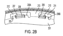
図2Bを参照すると、本開示の実施形態によるリアクションプレートの細部を示す機械図が示されている。リアクションプレート201の周辺部の近くのセクションが例示されている。ウェビング213は、リアクションプレート201の平坦部分から上方に湾曲され得る。2つの結合窓211及び212が存在し得る。第1の結合窓212は、駆動トルク伝達歯206A及びコーストトルク伝達歯205と一緒に構成され得、これに対して、第2の結合窓211は、単一の駆動トルク伝達歯206Bと一緒に構成され得る。
2B, a mechanical diagram showing details of a reaction plate according to an embodiment of the present disclosure is shown. A section near the periphery of the
結合窓212は、ピストン204(図示せず)に結合された第1のトルク伝達タブ207、及び外側クラッチプレート202(図示せず)に結合された第2のトルク伝達タブ208を収容するように構成され得る。トルク伝達タブ207及び208は、駆動トルク伝達歯206Aとコーストトルク伝達歯205との間で嵌合することができる。駆動モードにおいて、トルクは、トルク伝達タブ207及び208によって、トルク伝達歯206Aを介して、ピストン204と外側クラッチプレート202との間で伝えられる。コーストモードにおいて、トルクは、トルク伝達タブ207及び208によって、トルク伝達歯205を介して、ピストン204(図示せず)と外側クラッチプレート202(図示せず)との間で伝えられる。
The
結合窓211は、ピストン204(図示せず)に結合された第1のトルク伝達タブ209、及び外側クラッチプレート202(図示せず)に結合された第2のトルク伝達タブ210を収容するように構成されている。トルク伝達タブ209及び210は、駆動トルク伝達歯206Bに隣接して嵌合する。駆動モードにおいて、トルクは、トルク伝達タブ209及び210によって、トルク伝達歯206Bを介して、ピストン204(図示せず)と外側クラッチプレート202(図示せず)との間で伝えられる。コーストモードにおいて、トルクは、結合窓211内のピストン204(図示せず)と外側クラッチプレート202(図示せず)との間では伝えられない。
The
当業者は、第1の結合窓212が第2の結合窓211よりも広くして、その2つのトルク伝達歯206A及び205を収容することができることを理解するであろう。これは、ウェビング213が耐久性にとって最も重大なリアクションプレート201の一部とすることができるため、それを強化するウェビング213の領域を増加させることができる。そのような当業者はまた、トルク伝達タブ207及び208のペアが、トルク伝達タブ209及び210のペアと同じ幅である必要がなく、トルク伝達タブ207、208、209、及び210のペアの幅、結合窓211及び212の幅、並びにトルク伝達歯205、206A、及び206Bの幅が、本発明の任意の特定の実施形態では、設計選択の問題であることに気付くであろう。
Those skilled in the art will appreciate that the
図2Cは、本開示の実施形態によるリアクションプレートの細部を示す機械図が示されている。リアクションプレート201のセクションが例示されている。特定の実施形態では、実質的に、リアクションプレート201の周辺部の1/4が示される。図に示されているものは、そのトルク伝達タブ205及び206Aを有する第1の結合窓212の2つの例である。また、図に示されているものは、その単一のトルク伝達タブ206Bを有する第2の結合窓211の2つの例でもある。いくつかの実施形態では、結合窓211の例は、結合窓212の例と交替することができ、これに対して、他の実施形態では、結合窓211及び212の例の異なる配置を使用することができる。様々な実施形態では、ウェビング213の幅は、結合窓211の例と、結合窓212の例との間で実質的に同じであってもよく、これに対して、様々な他の実施形態では、ウェビング213の異なる配置のセグメントを使用してもよい。
2C is a mechanical diagram showing details of a reaction plate according to an embodiment of the present disclosure. A section of the
また、図には、駆動トルク標識矢印214及びコーストトルク標識矢印215が示されている。これらの矢印は、単なる例示的なものであり、物理的に、リアクションプレート201の一部ではない。逆に、駆動トルク標識矢印214は、駆動モードにおけるトルク伝達の方向を示し、これに対して、コーストトルク標識矢印215は、コーストモードにおけるトルク伝達の方向を示し、これは、駆動モードの方向とは反対である。
Also shown in the figure are a drive
図2Dを参照すると、本開示の実施形態によるリアクションプレートを有するトルクコンバータの機械図が示されている。トルクコンバータ200の一部が、断面図に示され、リアクションプレート201を備え得、リアクションプレートは、レーザ溶接又はある類似の方法によって、トルクコンバータカバー203に結合することができる。また、図には、ピストン204及び外側クラッチプレート202が例示されている。この特定の断面は、211/212とラベル付けされた結合窓を通っている。それは、第1の結合窓212か又は第2の結合窓211のいずれかであり、各々の断面が同じであるため、図においてそれらを区別することは不可能である。また、図には、背景にウェビング213の一部、背景に2つの他の結合窓211/212、ピストン204に結合されたトルク伝達タブ207/209、及び外側クラッチプレート202に結合されたトルク伝達タブ208/210も示されている。トルク伝達歯は、トルク伝達タブ207、208、209、及び210、並びにウェビング213によって、視界からは隠れて見えない。
2D, a mechanical diagram of a torque converter having a reaction plate according to an embodiment of the present disclosure is shown. A portion of a
図3は、本開示の実施形態による、リアクションプレートを有するトルクコンバータを動作させるプロセス300のフローチャートが示されている。プロセス300は、第1の複数のトルク転移歯によって、リアクションプレートを介して、ピストンを外側クラッチプレートに結合することから開始することができる(ブロック310)。ピストン及び外側クラッチプレートは、それぞれ、第1の複数のトルク伝達タブ及び第2の複数のトルク伝達タブを備えることができる。これらのトルク伝達タブを使用して、第1の複数のトルク伝達歯と係合させ、駆動モード動作で駆動トルクを伝えることができる(ブロック320)。
3 illustrates a flow chart of a
ピストンはまた、第2の複数のトルク転移歯を更に備えるリアクションプレートを介して、外側クラッチプレートに結合することができる(ブロック330)。第1の複数のトルク伝達タブ及び第2の複数のトルク伝達タブを使用して、第2の複数のトルク伝達歯と係合させ、コーストモード動作でコーストトルクを伝えることができる(ブロック340)。リアクションプレートは、第1の複数のトルク伝達タブ及び第2の複数のトルク伝達タブと係合するための第1の複数の窓を更に備えることができる。第1の複数の窓の各々は、第1の複数のトルク伝達歯のうちの1つ、及び第2の複数のトルク伝達歯のうちの1つを備えることができる。 The piston may also be coupled to the outer clutch plate via a reaction plate further comprising a second plurality of torque transfer teeth (Block 330). The first and second plurality of torque transfer tabs may be used to engage with the second plurality of torque transfer teeth to transmit coast torque in a coast mode operation (Block 340). The reaction plate may further comprise a first plurality of windows for engaging with the first and second plurality of torque transfer tabs. Each of the first plurality of windows may comprise one of the first plurality of torque transfer teeth and one of the second plurality of torque transfer teeth.
ピストンはまた、第3の複数のトルク伝達タブを備えることもでき、外側クラッチプレートはまた、第4の複数のトルク伝達タブを備えることもできる。ピストンはまた、第3の複数のトルク転移歯によって、リアクションプレートを介して、外側クラッチプレートに結合することもできる(ブロック350)。第3の複数のトルク伝達タブ、及び第4の複数のトルク伝達タブを使用して、第3の複数のトルク伝達歯と係合させ、駆動モード動作で駆動トルクを伝えることができる(ブロック360)。リアクションプレートは、第3の複数のトルク伝達タブ及び第4の複数のトルク伝達タブと係合するための第2の複数の窓を更に備えることができる。第2の複数の窓の各々は、第3の複数のトルク伝達歯のうちの1つを備えることができる。 The piston may also include a third plurality of torque transfer tabs, and the outer clutch plate may also include a fourth plurality of torque transfer tabs. The piston may also be coupled to the outer clutch plate through the reaction plate by the third plurality of torque transfer teeth (Block 350). The third plurality of torque transfer tabs and the fourth plurality of torque transfer tabs may be used to engage with the third plurality of torque transfer teeth to transmit drive torque in drive mode operation (Block 360). The reaction plate may further include a second plurality of windows for engaging with the third plurality of torque transfer tabs and the fourth plurality of torque transfer tabs. Each of the second plurality of windows may include one of the third plurality of torque transfer teeth.
本明細書に示され、かつ詳細に説明されたような情報は、本開示の上述の目的、本開示の現在好ましい実施形態を達成することが完全に可能であり、したがって、本開示によって広く想定される主題を表している。本開示の範囲は、当業者にとって明白になり得る他の実施形態を完全に包含し、したがって、添付の特許請求の範囲以外の何ものによっても限定されるべきではない。単数形で記載されている要素へのいかなる言及も、明示的にそのように記述されていない限り、「1つ及び1つのみ」を意味することを意図されておらず、逆に「1つ以上」を意味する。当業者によって評価されるときに、上述の好ましい実施形態及び追加の実施形態の要素に対する全ての構造的及び機能的等価物は、本明細書によって、参照により明示的に組み込まれ、本特許請求の範囲によって包含されるべきものと企図される。 The information as shown and described in detail herein is fully capable of achieving the above-mentioned objectives of the present disclosure, the presently preferred embodiments of the present disclosure, and thus represents the subject matter broadly envisioned by the present disclosure. The scope of the present disclosure fully encompasses other embodiments that may become apparent to those skilled in the art, and therefore should not be limited by anything other than the scope of the appended claims. Any reference to an element described in the singular is not intended to mean "one and only one" unless expressly so stated, but rather means "one or more". All structural and functional equivalents to the elements of the above-described preferred and additional embodiments, as appreciated by those skilled in the art, are hereby expressly incorporated by reference and contemplated to be encompassed by the scope of the present claims.
更に、本開示によって解決されるように要求される各問題及びあらゆる問題に対処するためのシステム又は方法のための要件は存在せず、そのような問題に対して本特許請求の範囲によって包含される解決策のための要件も存在しない。更に、本開示の要素、構成要素、又は方法ステップは、要素、構成要素、又は方法ステップが特許請求の範囲に明示的に列挙されているかどうかにかかわらず、公に対して専有されることが企図される。当業者にとって明らかであるように、添付の特許請求の範囲に記述されているように、形状、材料、加工物、及び作製材料詳細の様々な変更及び修正は、本開示の趣旨及び範囲を逸脱することなく行うことができるが、これも、本開示によって包含されるものである。 Furthermore, there is no requirement for a system or method to address each and every problem sought to be solved by the present disclosure, nor for a solution to such problems to be encompassed by the present claims. Moreover, any element, component, or method step of the present disclosure is intended to be publicly appropriated, regardless of whether the element, component, or method step is expressly recited in the claims. As will be apparent to those skilled in the art, various changes and modifications in shape, material, workmanship, and details of construction may be made without departing from the spirit and scope of the present disclosure, as set forth in the appended claims, which are also encompassed by the present disclosure.
100 自動車駆動トレイン
110 エンジン
111 ギアボックス出力シャフト
120 自動変速機
121 トルクコンバータ
122 中間シャフト
123 ギアボックス
124 トランスミッション出力シャフト
130 駆動輪
200 トルクコンバータ
201 リアクションプレート
202 外側クラッチプレート
203 トルクコンバータカバー
204 ピストン
205 コーストトルク伝達歯
206A 駆動トルク伝達歯
206B 駆動トルク伝達歯
207 トルク伝達タブ
208 トルク伝達タブ
209 トルク伝達タブ
210 トルク伝達タブ
211 第2の結合窓
212 第1の結合窓
213 ウェビング
214 駆動トルク標識矢印
215 コーストトルク標識矢印
300 リアクションプレートを有するトルクコンバータを動作させるプロセスのフローチャート
310 フローチャートボックス
320 フローチャートボックス
330 フローチャートボックス
340 フローチャートボックス
350 フローチャートボックス
360 フローチャートボックス
REFERENCE SIGNS
Claims (20)
第1の複数のトルク伝達タブを備えるピストンであって、
前記第1の複数のトルク伝達タブの第1の部分が、駆動トルク及びコーストトルクの両方を伝達するように構成されており、
前記第1の複数のトルク伝達タブの第2の部分が、駆動トルクのみを伝達するように構成されている、ピストンと、
第2の複数のトルク伝達タブを備える外側クラッチプレートであって、
前記第2の複数のトルク伝達タブの第1の部分が、駆動トルク及びコーストトルクの両方を伝達するように構成されており、
前記第2の複数のトルク伝達タブの第2の部分が、駆動トルクのみを伝達するように構成れている、外側クラッチプレートと、
前記第1の複数のトルク伝達タブ及び前記第2の複数のトルク伝達タブを通って、前記ピストンを前記外側クラッチプレートに結合するリアクションプレートと、を備え、
前記第1の複数のトルク伝達タブの前記第1の部分及び前記第2の複数のトルク伝達タブの前記第2の部分が、前記駆動トルク及びコーストトルクの両方の伝達のために構成された前記リアクションプレート内の第1の複数の結合窓内で一緒に結合され、かつ
前記第1の複数のトルク伝達タブの前記第2の部分及び前記第2の複数のトルク伝達タブの前記第2の部分が、前記コーストトルクのみの伝達のために構成された前記リアクションプレート内の第2の複数の結合窓内で一緒に結合される、トルクコンバータ。 A torque converter comprising:
a piston including a first plurality of torque transfer tabs,
a first portion of the first plurality of torque transmission tabs configured to transmit both drive torque and coast torque;
a piston, a second portion of the first plurality of torque transmission tabs configured to transmit only drive torque;
an outer clutch plate including a second plurality of torque transfer tabs,
a first portion of the second plurality of torque transmission tabs configured to transmit both drive torque and coast torque;
an outer clutch plate, a second portion of the second plurality of torque transmission tabs configured to transmit only driving torque;
a reaction plate coupling the piston to the outer clutch plate through the first and second plurality of torque transfer tabs,
a first portion of the first plurality of torque transmission tabs and a second portion of the second plurality of torque transmission tabs coupled together within a first plurality of coupling windows in the reaction plate configured for the transmission of both the drive torque and the coasting torque, and a second portion of the first plurality of torque transmission tabs and a second portion of the second plurality of torque transmission tabs coupled together within a second plurality of coupling windows in the reaction plate configured for the transmission of only the coasting torque.
前記第1の複数のトルク伝達タブの前記第1の部分の1つが、前記第1の複数の結合窓の各々内の2つの前記トルク伝達歯の間で、前記第2の複数のトルク伝達タブの前記第1の部分の1つに結合される、請求項2に記載のトルクコンバータ。 3. The torque converter of claim 2, wherein a first torque transmission tooth and a second torque transmission tooth are present within each of said first plurality of coupling windows, and one of said first portions of said first plurality of torque transmission tabs is coupled to one of said first portions of said second plurality of torque transmission tabs between two of said torque transmission teeth in each of said first plurality of coupling windows.
前記第1の複数のトルク伝達タブの前記第2の部分の1つが、前記第2の複数の結合窓内の前記第3のトルク伝達歯に隣接する前記第2の複数のトルク伝達タブの前記第2の部分の1つに結合される、請求項3に記載のトルクコンバータ。 4. The torque converter of claim 3, wherein a third torque transmission tooth is present within each of said second plurality of coupling windows, and one of said second portions of said first plurality of torque transmission tabs is coupled to one of said second portions of said second plurality of torque transmission tabs adjacent said third torque transmission tooth in said second plurality of coupling windows.
前記第1の複数の結合窓の各々内の前記第2のトルク伝達歯が、前記駆動方向とは反対であるコースト方向にトルクを伝えるように構成されたコーストトルク伝達歯であり、かつ
前記第2の複数の結合窓の各々内の前記第3のトルク伝達歯が、前記駆動方向にトルクを伝えるように構成された駆動トルク伝達歯である、請求項4に記載のトルクコンバータ。 the first torque transmission tooth in each of the first plurality of coupling windows is a drive torque transmission tooth configured to transmit torque in a drive direction;
5. The torque converter of claim 4, wherein the second torque transmission tooth in each of the first plurality of coupling windows is a coast torque transmission tooth configured to transmit torque in a coast direction opposite the driving direction, and the third torque transmission tooth in each of the second plurality of coupling windows is a drive torque transmission tooth configured to transmit torque in the driving direction.
前記第2の複数の結合窓の各々が、第2の幅を有し、かつ
前記第1の幅が、前記第2の幅よりも大きい、請求項5に記載のトルクコンバータ。 each of the first plurality of coupling windows has a first width;
6. The torque converter of claim 5, wherein each of said second plurality of coupling windows has a second width, and wherein said first width is greater than said second width.
前記第2の複数のトルク伝達タブの前記第1の部分の各々が、前記第3の幅を有し、
前記第1の複数のトルク伝達タブの前記第2の部分の各々が、第4の幅を有し、
前記第2の複数のトルク伝達タブの前記第2の部分の各々が、前記第4の幅を有し、かつ
前記第3の幅が、前記第4の幅よりも大きい、請求項5に記載のトルクコンバータ。 each of the first portions of the first plurality of torque transmission tabs has a third width;
each of the first portions of the second plurality of torque transmission tabs having the third width;
each of the second portions of the first plurality of torque transfer tabs has a fourth width;
6. The torque converter of claim 5, wherein each of said second portions of said second plurality of torque transmitting tabs has said fourth width, and said third width is greater than said fourth width.
前記第1の複数の結合窓及び前記第2の複数の結合窓が、前記リアクションプレートの周辺部の周りの交互の位置にある、請求項5に記載のトルクコンバータ。 6. The torque converter of claim 5, wherein a number of said first plurality of coupling windows is equal to a number of said second plurality of coupling windows, and said first plurality of coupling windows and said second plurality of coupling windows are in alternating positions around a periphery of said reaction plate.
メインプレート領域と、
前記メインプレート領域の外周部におけるウェビング領域であって、前記ウェビング領域が、前記メインプレート領域の平面から湾曲している、ウェビング領域と、
前記ウェビング領域において第1の幅を有する第1の複数の結合窓と、
前記ウェビング領域において第2の幅を有する第2の複数の結合窓と、を備える、リアクションプレート。 1. A reaction plate for a torque converter, comprising:
A main plate region;
a webbing region at a periphery of the main plate region, the webbing region curving out of the plane of the main plate region;
a first plurality of coupling windows having a first width in the webbing region;
a second plurality of coupling windows having a second width in the webbing region.
前記第2の結合窓が各々、第3のトルク伝達歯を有する、請求項11に記載のリアクションプレート。 each of the first coupling windows has a first torque transmitting tooth and a second torque transmitting tooth;
The reaction plate of claim 11 , wherein each of the second coupling windows has a third torque transmitting tooth.
前記第1の複数の結合窓の各々内の前記第2のトルク伝達歯が、前記駆動方向とは反対であるコースト方向にトルクを伝えるように構成されたコーストトルク伝達歯であり、かつ
前記第2の複数の結合窓の各々内の前記第3のトルク伝達歯が、前記駆動方向にトルクを伝えるように構成された駆動トルク伝達歯である、請求項12に記載のリアクションプレート。 the first torque transmission tooth in each of the first plurality of coupling windows is a drive torque transmission tooth configured to transmit torque in a drive direction;
13. The reaction plate of claim 12, wherein the second torque transmission tooth in each of the first plurality of coupling windows is a coast torque transmission tooth configured to transmit torque in a coast direction opposite the drive direction, and the third torque transmission tooth in each of the second plurality of coupling windows is a drive torque transmission tooth configured to transmit torque in the drive direction.
第1の複数のトルク伝達タブを備えるピストンと第2の複数のトルク伝達タブを備える外側クラッチプレートとの間で、駆動トルク及びコーストトルクを伝えることと、
リアクションプレートの第1の複数のトルク伝達歯、及び前記リアクションプレートの第2の複数のトルク伝達歯を介して、前記第1の複数のトルク伝達タブを前記第2の複数のトルク伝達タブに結合することと、
第3の複数のトルク伝達タブを更に備える前記ピストンと第4の複数のトルク伝達タブを更に備える前記外側クラッチプレートとの間で駆動トルクのみを伝えることと、
前記リアクションプレートの第3の複数のトルク伝達歯を介して、前記第3の複数のトルク伝達タブを前記第4の複数のトルク伝達タブに結合することと、含む、方法。 1. A method of operating a torque converter, comprising:
transmitting drive torque and coast torque between a piston having a first plurality of torque transfer tabs and an outer clutch plate having a second plurality of torque transfer tabs;
coupling the first plurality of torque transmission tabs to the second plurality of torque transmission tabs via a first plurality of torque transmission teeth of a reaction plate and a second plurality of torque transmission teeth of the reaction plate;
transmitting only drive torque between said piston further comprising a third plurality of torque transfer tabs and said outer clutch plate further comprising a fourth plurality of torque transfer tabs;
and coupling the third plurality of torque transmission tabs to the fourth plurality of torque transmission tabs via a third plurality of torque transmission teeth of the reaction plate.
前記第1の複数の結合窓が各々、前記第1の複数の伝達歯のうちの1つと、前記第2の複数の伝達歯のうちの1つと、を備え、
前記リアクションプレートが、前記第3の複数のトルク伝達タブと前記第4の複数の伝達タブとの間でトルクを伝えるように構成された第2の複数の結合窓を更に備え、かつ
前記第2の複数の結合窓が各々、前記第3の複数の伝達歯のうちの1つを備える、請求項18に記載の方法。 the reaction plate includes a first plurality of coupling windows configured to transmit torque between the first plurality of torque transmission tabs and the second plurality of transmission tabs;
each of the first plurality of coupling windows includes one of the first plurality of transmitting teeth and one of the second plurality of transmitting teeth;
20. The method of claim 18, wherein the reaction plate further comprises a second plurality of coupling windows configured to transmit torque between the third plurality of torque transmission tabs and the fourth plurality of transmission tabs, and wherein the second plurality of coupling windows each comprise one of the third plurality of transmission teeth.
コーストトルクが、前記第2の複数の伝達歯を介して、前記ピストンと前記外側クラッチプレートとの間で伝達され、かつ
駆動トルクが、前記第3の複数の伝達歯を介して、前記ピストンと前記外側クラッチプレートとの間で伝達される、請求項19に記載の方法。 a driving torque is transmitted between the piston and the outer clutch plate via the first plurality of transmission teeth;
20. The method of claim 19, wherein a coasting torque is transmitted between the piston and the outer clutch plate via the second plurality of transmission teeth, and a drive torque is transmitted between the piston and the outer clutch plate via the third plurality of transmission teeth.
Applications Claiming Priority (3)
| Application Number | Priority Date | Filing Date | Title |
|---|---|---|---|
| US17/573,428 | 2022-01-11 | ||
| US17/573,428 US11560941B1 (en) | 2022-01-11 | 2022-01-11 | Reaction plate with an uneven number of tabs in drive and coast |
| PCT/US2022/052073 WO2023136893A1 (en) | 2022-01-11 | 2022-12-07 | Reaction plate with an uneven number of tabs in drive and coast |
Publications (2)
| Publication Number | Publication Date |
|---|---|
| JP2024543143A JP2024543143A (en) | 2024-11-19 |
| JP7686887B2 true JP7686887B2 (en) | 2025-06-02 |
Family
ID=84978002
Family Applications (1)
| Application Number | Title | Priority Date | Filing Date |
|---|---|---|---|
| JP2024531193A Active JP7686887B2 (en) | 2022-01-11 | 2022-12-07 | Reaction plate with odd number of tabs on drive and coast |
Country Status (7)
| Country | Link |
|---|---|
| US (1) | US11560941B1 (en) |
| JP (1) | JP7686887B2 (en) |
| KR (1) | KR20240089574A (en) |
| CN (1) | CN118159757A (en) |
| DE (1) | DE112022006376T5 (en) |
| MX (1) | MX2024004951A (en) |
| WO (1) | WO2023136893A1 (en) |
Families Citing this family (2)
| Publication number | Priority date | Publication date | Assignee | Title |
|---|---|---|---|---|
| US11815134B2 (en) * | 2022-02-14 | 2023-11-14 | Schaeffler Technologies AG & Co. KG | Anti-rattle feature for clutch plate |
| US11898627B1 (en) * | 2023-06-07 | 2024-02-13 | Schaeffler Technologies AG & Co. KG | Clutch plate anti-rattle feature |
Citations (3)
| Publication number | Priority date | Publication date | Assignee | Title |
|---|---|---|---|---|
| JP2008138797A (en) | 2006-12-04 | 2008-06-19 | Exedy Corp | Lock-up device and fluid torque transmission device having same |
| JP2015203460A (en) | 2014-04-15 | 2015-11-16 | トヨタ自動車株式会社 | torque converter |
| US20180058562A1 (en) | 2016-08-25 | 2018-03-01 | Valeo Embrayages | Lock-up clutch and torsional vibration damper for hydrokinetic torque coupling device, and related methods |
Family Cites Families (8)
| Publication number | Priority date | Publication date | Assignee | Title |
|---|---|---|---|---|
| US2174240A (en) * | 1937-11-10 | 1939-09-26 | Carlyle Johnson Machine Co | Clutch |
| US2738864A (en) * | 1951-08-18 | 1956-03-20 | Borg Warner | Clutch belleville spring type |
| US4413711A (en) * | 1981-03-30 | 1983-11-08 | Borg-Warner Corporation | Extended travel damper in a lock-up clutch for a torque converter |
| US8939270B2 (en) * | 2012-04-16 | 2015-01-27 | Gm Global Technology Operations, Llc | Tabbed separation clutch plate |
| US10145458B2 (en) * | 2016-01-22 | 2018-12-04 | Schaeffler Technologies AG & Co. KG | Torque converter drive assembly including bias spring and axially movable turbine |
| JP6637802B2 (en) * | 2016-03-18 | 2020-01-29 | 株式会社エクセディ | Vibration reduction device |
| US20200386274A1 (en) * | 2019-06-07 | 2020-12-10 | Honda Motor Co., Ltd. | Torque damper apparatus |
| US20210143717A1 (en) | 2019-11-08 | 2021-05-13 | Schaeffler Technologies AG & Co. KG | Resolver stator clamping plate |
-
2022
- 2022-01-11 US US17/573,428 patent/US11560941B1/en active Active
- 2022-12-07 WO PCT/US2022/052073 patent/WO2023136893A1/en not_active Ceased
- 2022-12-07 KR KR1020247015590A patent/KR20240089574A/en active Pending
- 2022-12-07 DE DE112022006376.9T patent/DE112022006376T5/en active Pending
- 2022-12-07 JP JP2024531193A patent/JP7686887B2/en active Active
- 2022-12-07 MX MX2024004951A patent/MX2024004951A/en unknown
- 2022-12-07 CN CN202280071943.6A patent/CN118159757A/en active Pending
Patent Citations (3)
| Publication number | Priority date | Publication date | Assignee | Title |
|---|---|---|---|---|
| JP2008138797A (en) | 2006-12-04 | 2008-06-19 | Exedy Corp | Lock-up device and fluid torque transmission device having same |
| JP2015203460A (en) | 2014-04-15 | 2015-11-16 | トヨタ自動車株式会社 | torque converter |
| US20180058562A1 (en) | 2016-08-25 | 2018-03-01 | Valeo Embrayages | Lock-up clutch and torsional vibration damper for hydrokinetic torque coupling device, and related methods |
Also Published As
| Publication number | Publication date |
|---|---|
| DE112022006376T5 (en) | 2024-12-19 |
| CN118159757A (en) | 2024-06-07 |
| MX2024004951A (en) | 2024-05-08 |
| KR20240089574A (en) | 2024-06-20 |
| JP2024543143A (en) | 2024-11-19 |
| WO2023136893A1 (en) | 2023-07-20 |
| US11560941B1 (en) | 2023-01-24 |
Similar Documents
| Publication | Publication Date | Title |
|---|---|---|
| JP7686887B2 (en) | Reaction plate with odd number of tabs on drive and coast | |
| US7367919B2 (en) | Transmission configuration and method for controlling a transmission | |
| CN107683218B (en) | Transmission for a motor vehicle, powertrain for a hybrid vehicle, and method for operating such a powertrain | |
| US20090032364A1 (en) | Method and apparatus for lash prevention using coil springs | |
| US20180073610A1 (en) | Transmission and Drivetrain for a Motor Vehicle | |
| JP2013517175A (en) | Hybrid electric vehicle drive system and control system for controlling hybrid electric vehicle drive system | |
| US4635495A (en) | Multi-speed reversible power transmission | |
| US7124869B2 (en) | Multi-plate clutch, particularly for a double clutch transmission | |
| US10406907B2 (en) | Transmission for a motor vehicle and hybrid drivetrain provided therewith | |
| CN111219444B (en) | A torsional vibration damping adapter for shifting system without friction ring | |
| US20070253823A1 (en) | Turbine blade tab attachment means for a torque converter dampening spring retainer and a method of manufacturing said attachment means | |
| US7918645B2 (en) | Torque converter with brazed turbine | |
| CN113646199A (en) | Hybrid transmission and motor vehicle | |
| CN113266653A (en) | Friction clutch for the friction-and form-fitting transmission of torque | |
| CN103818231B (en) | Transmission engine assembly | |
| CN113677550B (en) | Hybrid transmission and motor vehicle | |
| US10495187B2 (en) | Vehicle transmission and drivetrain | |
| US10315503B2 (en) | Transmission for a motor vehicle and hybrid drive train provided therewith | |
| CN106195158A (en) | Many gears automatic transmission for vehicle | |
| JPH0893878A (en) | Motive power transmission mechanism | |
| US7955207B2 (en) | Torque converter with planetary gear set | |
| US11898627B1 (en) | Clutch plate anti-rattle feature | |
| US20080128237A1 (en) | Clutch arrangement for a motor vehicle | |
| JP2008309292A (en) | Snap ring of hydraulic friction engagement device for vehicle | |
| JP2004340226A (en) | Automatic transmission speed detection structure |
Legal Events
| Date | Code | Title | Description |
|---|---|---|---|
| A621 | Written request for application examination |
Free format text: JAPANESE INTERMEDIATE CODE: A621 Effective date: 20240523 |
|
| TRDD | Decision of grant or rejection written | ||
| A977 | Report on retrieval |
Free format text: JAPANESE INTERMEDIATE CODE: A971007 Effective date: 20250410 |
|
| A01 | Written decision to grant a patent or to grant a registration (utility model) |
Free format text: JAPANESE INTERMEDIATE CODE: A01 Effective date: 20250422 |
|
| A61 | First payment of annual fees (during grant procedure) |
Free format text: JAPANESE INTERMEDIATE CODE: A61 Effective date: 20250521 |
|
| R150 | Certificate of patent or registration of utility model |
Ref document number: 7686887 Country of ref document: JP Free format text: JAPANESE INTERMEDIATE CODE: R150 |