JP7686885B2 - Radial Line Slot Antenna Array - Google Patents
Radial Line Slot Antenna Array Download PDFInfo
- Publication number
- JP7686885B2 JP7686885B2 JP2024521181A JP2024521181A JP7686885B2 JP 7686885 B2 JP7686885 B2 JP 7686885B2 JP 2024521181 A JP2024521181 A JP 2024521181A JP 2024521181 A JP2024521181 A JP 2024521181A JP 7686885 B2 JP7686885 B2 JP 7686885B2
- Authority
- JP
- Japan
- Prior art keywords
- slots
- slot
- array
- antenna
- capacitance
- Prior art date
- Legal status (The legal status is an assumption and is not a legal conclusion. Google has not performed a legal analysis and makes no representation as to the accuracy of the status listed.)
- Active
Links
Images
Classifications
-
- H—ELECTRICITY
- H01—ELECTRIC ELEMENTS
- H01Q—ANTENNAS, i.e. RADIO AERIALS
- H01Q21/00—Antenna arrays or systems
- H01Q21/29—Combinations of different interacting antenna units for giving a desired directional characteristic
-
- H—ELECTRICITY
- H01—ELECTRIC ELEMENTS
- H01Q—ANTENNAS, i.e. RADIO AERIALS
- H01Q13/00—Waveguide horns or mouths; Slot antennas; Leaky-waveguide antennas; Equivalent structures causing radiation along the transmission path of a guided wave
- H01Q13/10—Resonant slot antennas
- H01Q13/18—Resonant slot antennas the slot being backed by, or formed in boundary wall of, a resonant cavity ; Open cavity antennas
-
- H—ELECTRICITY
- H01—ELECTRIC ELEMENTS
- H01Q—ANTENNAS, i.e. RADIO AERIALS
- H01Q1/00—Details of, or arrangements associated with, antennas
- H01Q1/52—Means for reducing coupling between antennas; Means for reducing coupling between an antenna and another structure
- H01Q1/521—Means for reducing coupling between antennas; Means for reducing coupling between an antenna and another structure reducing the coupling between adjacent antennas
- H01Q1/523—Means for reducing coupling between antennas; Means for reducing coupling between an antenna and another structure reducing the coupling between adjacent antennas between antennas of an array
-
- H—ELECTRICITY
- H01—ELECTRIC ELEMENTS
- H01Q—ANTENNAS, i.e. RADIO AERIALS
- H01Q13/00—Waveguide horns or mouths; Slot antennas; Leaky-waveguide antennas; Equivalent structures causing radiation along the transmission path of a guided wave
- H01Q13/10—Resonant slot antennas
- H01Q13/103—Resonant slot antennas with variable reactance for tuning the antenna
-
- H—ELECTRICITY
- H01—ELECTRIC ELEMENTS
- H01Q—ANTENNAS, i.e. RADIO AERIALS
- H01Q19/00—Combinations of primary active antenna elements and units with secondary devices, e.g. with quasi-optical devices, for giving the antenna a desired directional characteristic
- H01Q19/06—Combinations of primary active antenna elements and units with secondary devices, e.g. with quasi-optical devices, for giving the antenna a desired directional characteristic using refracting or diffracting devices, e.g. lens
- H01Q19/067—Combinations of primary active antenna elements and units with secondary devices, e.g. with quasi-optical devices, for giving the antenna a desired directional characteristic using refracting or diffracting devices, e.g. lens using a hologram
-
- H—ELECTRICITY
- H01—ELECTRIC ELEMENTS
- H01Q—ANTENNAS, i.e. RADIO AERIALS
- H01Q21/00—Antenna arrays or systems
- H01Q21/0006—Particular feeding systems
- H01Q21/0012—Radial guide fed arrays
-
- H—ELECTRICITY
- H01—ELECTRIC ELEMENTS
- H01Q—ANTENNAS, i.e. RADIO AERIALS
- H01Q21/00—Antenna arrays or systems
- H01Q21/0006—Particular feeding systems
- H01Q21/0031—Parallel-plate fed arrays; Lens-fed arrays
-
- H—ELECTRICITY
- H01—ELECTRIC ELEMENTS
- H01Q—ANTENNAS, i.e. RADIO AERIALS
- H01Q3/00—Arrangements for changing or varying the orientation or the shape of the directional pattern of the waves radiated from an antenna or antenna system
- H01Q3/24—Arrangements for changing or varying the orientation or the shape of the directional pattern of the waves radiated from an antenna or antenna system varying the orientation by switching energy from one active radiating element to another, e.g. for beam switching
Landscapes
- Variable-Direction Aerials And Aerial Arrays (AREA)
- Waveguide Aerials (AREA)
Description
本発明は、アンテナアレイに関する。態様は、ラジアルスロットラインアンテナアレイに関する。 The present invention relates to an antenna array. The embodiment relates to a radial slot line antenna array.
プラットフォーム中のアンテナ又はアンテナアレイのサイズ、重量、電力消費、及び実装コストは、法外に高くなる可能性があり、例えば、より低コスト又はより小型の代替形態を優先してある特定の所望の機能性が犠牲にされ得る、準最適な展開につながる。例えば、能動電子走査アンテナアレイ(AESA)及び受動電子走査アンテナアレイ(PESA)は、重く、高価であり、動作し、冷却を維持するために大量の電力を必要とする。同様に、受動反射器型アンテナは大きく、例えば(少なくとも)それらのサイズがプラットフォームの空気力学的輪郭に干渉する可能性がある現代の航空機などのある特定のプラットフォーム上での実装に貢献しない。 The size, weight, power consumption, and implementation cost of an antenna or antenna array in a platform can be prohibitive, leading to suboptimal deployment, where, for example, certain desired functionality may be sacrificed in favor of lower cost or smaller alternatives. For example, active electronically scanned antenna arrays (AESA) and passive electronically scanned antenna arrays (PESA) are heavy, expensive, and require large amounts of power to operate and keep cool. Similarly, passive reflector-type antennas are large and not conducive to implementation on certain platforms, such as modern aircraft, where (at least) their size may interfere with the aerodynamic profile of the platform.
コスト及びサイズを低減するために、アンテナ構造の中には、アンテナの素子を駆動するために単一の電圧源を使用し、それによって、構造の物理的サイズ及びその実装コストを低減するものがある。しかしながら、単一のソースのみを使用することによって、個々の素子は、選択的に制御されることができない。これは、従って、例えばアレイが走査されることができないので、放出されるビームに関して使用を制限する。位相シフタは、放出されたビームに対してある程度の制御を提供するために用いられることができるが、これらは、一般にフェライトベースであるため損失が多く、それによって非効率性につながる。逆に、各アンテナ素子に対して設けられた送信機は、放出されたビームの位相及び振幅の完全な制御を提供することができ、例えば走査を可能にする。しかしながら、そのようなシステムは高価であり、例えば駆動機構に必要とされる面積が増大する結果として、一般に大型である。それ故に、高価であり、及び/又は大きく/重いが、効率的であり、より制御可能であるアンテナを実装することと、より安価であり、及び/又はより小さく/より軽いが、あまり効率的でなく、あまり機能的に有用でないアンテナを実装することとの間には、しばしばトレードオフが存在する。 To reduce cost and size, some antenna structures use a single voltage source to drive the elements of the antenna, thereby reducing the physical size of the structure and its implementation costs. However, by using only a single source, the individual elements cannot be selectively controlled. This therefore limits their use with respect to emitted beams, for example, since the array cannot be scanned. Phase shifters can be used to provide some control over the emitted beam, but these are generally ferrite-based and therefore lossy, leading to inefficiencies. Conversely, a transmitter provided for each antenna element can provide full control of the phase and amplitude of the emitted beam, allowing for example scanning. However, such systems are expensive and generally large, for example as a result of the increased area required for the drive mechanism. Hence, there is often a trade-off between implementing an antenna that is expensive and/or large/heavy, but efficient and more controllable, and an antenna that is cheaper and/or smaller/lighter, but less efficient and less functionally useful.
本開示の第1の態様によると、予め構成されたスロットパターンを定義する複数のスロットを備えるホログラフィックラジアルラインスロットアンテナアレイについてのスロットアクティブ化構成のセットを生成するための方法であって、各スロットアクティブ化構成は、アンテナによって放出されるべき信号についてのビームパターンを定義する、方法が提供され、本方法は、アンテナに印加されるべき信号が存在する場合の複数のスロット間の相互結合についての測定値を生成することと、ここで、測定値は、アンテナについての散乱行列を定義する散乱パラメータのセットを備え、相互結合についての測定値を使用して、アレイについてのインピーダンスパラメータのセットを生成することと、スロットの両端に提供される可変性静電容量デバイスの静電容量の値を調整することによって複数のスロットのうちの少なくとも1つの共振を制御することと、静電容量の値に関連付けられたビームパターンのアンテナ利得についての値を測定することと、ビームパターンについての利得の最も高い測定値をもたらす静電容量の最終値を選択することと、選択された静電容量の最終値に基づいてビームパターンについてのスロットアクティブ化構成を選択することとを備える。 According to a first aspect of the present disclosure, a method is provided for generating a set of slot activation configurations for a holographic radial line slot antenna array comprising a plurality of slots defining a preconfigured slot pattern, each slot activation configuration defining a beam pattern for a signal to be emitted by the antenna, the method comprising: generating measurements of mutual coupling between the plurality of slots in the presence of a signal to be applied to the antenna, the measurements comprising a set of scattering parameters defining a scattering matrix for the antenna, using the measurements of mutual coupling to generate a set of impedance parameters for the array; controlling resonance of at least one of the plurality of slots by adjusting capacitance values of variable capacitance devices provided at both ends of the slots; measuring values for antenna gain of the beam pattern associated with the capacitance values; selecting a final value of capacitance that results in the highest measured value of gain for the beam pattern; and selecting a slot activation configuration for the beam pattern based on the selected final value of capacitance.
第1の態様の実装形態では、スロット表面の両端に分散されたサブ波長スロット素子のセットは、低コスト、低重量、及び低姿勢である再構成可能なアンテナを生成するために、「オン」又は「オフ」に動的に切り替えられることができる。例では、アンテナの放射電力についての値が測定されることができる。アンテナについてのピーク利得の方向の電力についての値が測定されることができる。静電容量の値が存在する場合の複数のスロット間の相互結合についての更新された測定値が生成されることができる。 In an implementation of the first aspect, a set of sub-wavelength slot elements distributed across the slot surface can be dynamically switched "on" or "off" to generate a reconfigurable antenna that is low cost, low weight, and low profile. In an example, a value for the radiated power of the antenna can be measured. A value for the power in the direction of the peak gain for the antenna can be measured. An updated measurement of the mutual coupling between multiple slots when a capacitance value exists can be generated.
相互結合についての測定値は、複数のスロットのポートの両端に論理的に配設された抵抗素子を通って流れる電流のそれぞれの測定値を計算することによって生成されることができる。可変性静電容量デバイスの静電容量の値を調整することは、複数のスロットについての無効静電容量のそれぞれの値を調節することを備えることができる。アレイについてのインピーダンスパラメータのセットは、静電容量の値が存在する場合のスロット間の相互結合についての更新された測定値に変換されることができる。複数のスロットの励振についてのそれぞれの測定値が計算されることができる。複数のスロットのうちの少なくとも1つの共振は、容量性リアクタンスについての複数の離散値のうちの1つを使用して、スロットの両端に提供される可変性静電容量デバイスの静電容量の値を調整又は修正することによって制御されるか又は変化させられることができる。 The measurements of mutual coupling can be generated by calculating respective measurements of current flowing through resistive elements logically arranged across the ports of the plurality of slots. Adjusting the capacitance values of the variable capacitance devices can comprise adjusting respective values of reactive capacitance for the plurality of slots. The set of impedance parameters for the array can be converted into updated measurements of mutual coupling between the slots in the presence of capacitance values. Respective measurements of excitation of the plurality of slots can be calculated. The resonance of at least one of the plurality of slots can be controlled or changed by adjusting or modifying the capacitance value of the variable capacitance device provided across the slot using one of a plurality of discrete values for capacitive reactance.
本開示の第2の態様によると、予め構成されたスロットパターンを定義する複数のスロットを備えるホログラフィックラジアルラインスロットアンテナアレイについてのスロットアクティブ化構成のセットを生成するための命令で符号化された非一時的機械可読記憶媒体を提供され、各スロットアクティブ化構成は、アンテナによって放出されるべき信号についてのビームパターンを定義し、命令は、機械のプロセッサによって実行可能であって、それによって、機械に、アレイについての散乱パラメータのセットを使用してアレイについてのインピーダンス行列を生成することと、容量性リアクタンスを使用してスロットの共振周波数を同調して、それによって、アレイについての更新されたインピーダンス行列を生成することと、更新されたインピーダンス行列を使用して複数のスロットの周囲の電流のそれぞれの測定値を計算することと、電流の測定値及びインピーダンス行列を使用して複数のスロットの両端の電圧のそれぞれの測定値を計算することと、更新されたインピーダンス行列を散乱パラメータの更新されたセットに変換することと、散乱パラメータの更新されたセット及び電圧の測定値を使用して、アンテナについての放射パターンを計算することとを行わせる。 According to a second aspect of the present disclosure, a non-transitory machine-readable storage medium is provided that is encoded with instructions for generating a set of slot activation configurations for a holographic radial line slot antenna array having a plurality of slots that define a preconfigured slot pattern, each slot activation configuration defining a beam pattern for a signal to be emitted by the antenna, the instructions being executable by a processor of the machine to cause the machine to: generate an impedance matrix for the array using a set of scattering parameters for the array; tune the resonant frequencies of the slots using capacitive reactances to thereby generate an updated impedance matrix for the array; calculate respective measurements of currents around the plurality of slots using the updated impedance matrix; calculate respective measurements of voltages across the plurality of slots using the current measurements and the impedance matrix; convert the updated impedance matrix to an updated set of scattering parameters; and calculate a radiation pattern for the antenna using the updated set of scattering parameters and the voltage measurements.
第2の態様の実施形態では、共振周波数は、アレイの入力ポートから反射された電力を最小化するために、容量性リアクタンスの複数の異なる組み合わせを使用して最適化されることができる。共振周波数は、アレイの無負荷同軸ポートに送信される電力を最小化するために、容量性リアクタンスの複数の異なる組み合わせを使用して最適化されることができる。共振周波数は、選択された方向に放射される電力を最大化するために、容量性リアクタンスの複数の異なる組み合わせを使用して最適化されることができる。例では、スロットアクティブ化構成のセットが生成されることができ、各スロットアクティブ化構成は、アレイについての所与のビームパターンのために複数のスロットの各々についての容量性リアクタンスを定義する。スロットの共振周波数は、容量性リアクタンスについての複数の離散値のうちの1つを使用して同調されることができる。 In an embodiment of the second aspect, the resonant frequency can be optimized using multiple different combinations of capacitive reactance to minimize the power reflected from the input port of the array. The resonant frequency can be optimized using multiple different combinations of capacitive reactance to minimize the power transmitted to the unloaded coaxial port of the array. The resonant frequency can be optimized using multiple different combinations of capacitive reactance to maximize the power radiated in a selected direction. In an example, a set of slot activation configurations can be generated, each slot activation configuration defining a capacitive reactance for each of a plurality of slots for a given beam pattern for the array. The resonant frequency of the slot can be tuned using one of multiple discrete values for the capacitive reactance.
ここで、本発明の実施形態が、図面を参照して例としてのみ説明される。 Embodiments of the present invention will now be described, by way of example only, with reference to the drawings in which:
実例的な実施形態は、当業者が本明細書で説明されるシステム及びプロセスを具現化及び実装することを可能にするのに十分に詳細に以下で説明される。実施形態は多くの代替形態で提供されることができ、本明細書で記載される例に限定されるものとして解釈されるべきではないと理解することが重要である。 Illustrative embodiments are described below in sufficient detail to enable one skilled in the art to embody and implement the systems and processes described herein. It is important to understand that the embodiments may be provided in many alternative forms and should not be construed as being limited to the examples described herein.
それ故に、実施形態は、様々な方法で修正され、様々な代替形態を取ることができるが、その特定の実施形態が図面に示され、例として以下で詳細に説明される。開示される特定の形態に限定する意図はない。それどころか、添付の特許請求の範囲内に含まれる全ての修正形態、均等物、及び代替形態が含まれるべきである。実例的な実施形態の要素は、必要に応じて、図面及び発明を実施するための形態の全体を通して、一貫して同じ参照番号によって示される。 Thus, while the embodiments can be modified in various ways and can take various alternative forms, specific embodiments thereof are shown in the drawings and will be described in detail below by way of example. There is no intention to be limited to the particular forms disclosed. On the contrary, all modifications, equivalents, and alternatives falling within the scope of the appended claims are to be covered. Elements of illustrative embodiments will be consistently designated by the same reference numerals throughout the drawings and detailed description, where appropriate.
実施形態を説明するために本明細書で使用される専門用語は、範囲を限定することを意図されない。冠詞「a」、「an」、及び「the」は、それらが単一の指示対象を有するという点で単数形であるが、本文書での単数形の使用は、1つよりも多くの指示対象の存在を排除すべきではない。言い換えれば、単数形で言及される要素は、文脈上特に明記されていない限り、1つ以上の数を有することができる。「備える(comprises)」、「備えている(comprising)」、「含む(includes)」、及び/又は「含んでいる(including)」という用語は、本明細書で使用されるとき、記載された特徴、項目、ステップ、動作、要素、及び/又は構成要素の存在を指定するが、1つ以上の他の特徴、項目、ステップ、動作、要素、構成要素、及び/又はそれらのグループの存在又は追加を除外しないことを更に理解されたい。 The terminology used herein to describe the embodiments is not intended to be limiting in scope. The articles "a", "an", and "the" are singular in that they have a single referent, but the use of the singular in this document should not exclude the presence of more than one referent. In other words, an element referred to in the singular can have a number of one or more, unless the context clearly dictates otherwise. It is further understood that the terms "comprises", "comprising", "includes", and/or "including", as used herein, specify the presence of stated features, items, steps, operations, elements, and/or components, but do not exclude the presence or addition of one or more other features, items, steps, operations, elements, components, and/or groups thereof.
特に定義されない限り、本明細書で使用される全ての用語(技術用語及び科学用語を含む)は、当該技術分野において慣習的であるように解釈されるべきである。一般的な用法における用語はまた、関連技術分野において慣習的であるように解釈されるべきであり、本明細書でそのように明示的に定義されない限り、理想化された又は過度に形式的な意味で解釈されるべきではないことを更に理解されたい。 Unless otherwise defined, all terms (including technical and scientific terms) used herein should be interpreted as is customary in the relevant art. It should be further understood that terms in common usage should also be interpreted as is customary in the relevant art, and should not be interpreted in an idealized or overly formal sense unless expressly defined as such herein.
ラジアルラインスロットアンテナ(RSLA)は、放射素子、空洞、背景板、及び放射素子に信号を供給するためのフィードを備える低コストのアンテナ構造である。放射素子及び背景板は、一般に、空洞によって分離され、それによって、例えば同軸フィード又は導波管遷移部であり得るフィードによって中心で給電される平行板導波管を形成する、アルミニウム、銅、又は真鍮などの一対の金属円板を備える。平行板間の空洞は、誘電体材料などの低誘電率基板、又は遅波構造で充填されることができる。これは、遠方界パターンにおけるグレーティングローブの形成を防止するのに役立つことができる。放射素子及び背景板と連携して、空洞は、フィードからの信号を半径方向に伝播するように導く円形導波管として動作する。 A radial line slot antenna (RSLA) is a low-cost antenna structure that comprises a radiating element, a cavity, a background plate, and a feed for supplying a signal to the radiating element. The radiating element and background plate typically comprise a pair of metal disks, such as aluminum, copper, or brass, separated by a cavity, thereby forming a parallel plate waveguide fed at the center by a feed, which may be, for example, a coaxial feed or a waveguide transition. The cavity between the parallel plates can be filled with a low-permittivity substrate, such as a dielectric material, or a slow-wave structure. This can help prevent the formation of grating lobes in the far-field pattern. In conjunction with the radiating element and background plate, the cavity acts as a circular waveguide that directs the signal from the feed to propagate radially.
RLSAは、典型的には、概念的には複数のスロット対として構成された、放射素子中に複数の貫通スロット又はアパーチャを備え、その中では、各対が、放射素子の複数のスロット対の全てがアレイアンテナを形成するように、RLSA用のアンテナ素子として効果的に機能する。スロット対は、所与の偏波において所与の周波数で固定ビームを生成するように構成された所定のパターンで配置され、スロット対のスロットは、典型的には、それらの長軸が互いに直交するように互いに対して配置される。スロットの向きは、アレイ中の各スロットによって伝播される場のベクトルを分析することによって決定されることができ、スロット対のスロットを同相及び異相であるとみなし、次いで、これらのスロットのセットの累積和を使用して、所望の偏波を達成することが一般的である。 RLSAs typically comprise a number of through slots or apertures in a radiating element, conceptually arranged as a number of slot pairs, in which each pair effectively functions as an antenna element for the RLSA, such that all of the multiple slot pairs of a radiating element form an array antenna. The slot pairs are arranged in a predefined pattern arranged to generate a fixed beam at a given frequency at a given polarization, with the slots of a slot pair typically being arranged with respect to each other such that their major axes are mutually orthogonal. The orientation of the slots can be determined by analyzing the field vectors propagated by each slot in the array, and it is common to consider the slots of a slot pair as in-phase and out-of-phase, and then use a cumulative sum of these sets of slots to achieve the desired polarization.
一般に、小さいスロット間の相互結合の結果としてのRLSAアレイのアンテナ素子間の相互作用は、所与のビーム角度に対してアレイ両端に正しい振幅及び位相テーパを生成することを非常に困難にする。それ故に、スロットが定義された場所に固定され、スロットのサイズ及び位置のみが所与の方向に特定のビーム形状を生成するように最適化されることができるRLSAアレイは、一般に、同調可能なアンテナアレイのための実用的な候補であるとは考えられず、従って、1つの特定のビーム角度に対して最適化される。 In general, the interaction between antenna elements in an RLSA array as a result of mutual coupling between the small slots makes it very difficult to produce the correct amplitude and phase taper at both ends of the array for a given beam angle. Therefore, RLSA arrays in which the slots are fixed in defined locations and only the size and position of the slots can be optimized to produce a specific beam shape in a given direction are generally not considered to be practical candidates for tunable antenna arrays and are therefore optimized for one specific beam angle.
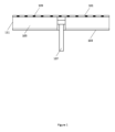
図1は、例によるRLSAアレイの概略図である。RLSAアレイは、放射素子101、空洞105、背景板103、及び同軸フィード107を備える。スロット109は、放射素子101中に設けられる。スロット109は、放射素子中に不連続性を形成する。それ故に、フィード107からの信号は、スロットの両端に電圧を発生させるであろう。壁111は、導電性材料であり得るか、又は開放されたままであり得る。スロットが放射素子中に位置付けられることができる多数の方法があり、本明細書で説明される方法は、スロットパターン全体に依存しない。例えば、2次元のスパイラルスロットアレイが使用されることができる。
Figure 1 is a schematic diagram of an RLSA array according to an example. The RLSA array comprises a
例によると、RLSA中でスロットアクティブ化構成のセットを生成するための方法が提供されて、それによって、アレイ両端の所望の振幅及び位相テーパが可能にされる。そのため、ビーム位置及び動作周波数が複数の所定の構成のうちの任意の1つに調整されることができる、同調可能なRLSAの形態のホログラフィックアンテナアレイが実装されることができる。 According to an example, a method is provided for generating a set of slot activation configurations in an RLSA, thereby enabling a desired amplitude and phase taper across the array. Thus, a holographic antenna array in the form of a tunable RLSA can be implemented in which the beam position and operating frequency can be adjusted to any one of a number of predefined configurations.
RLSAが走査可能となることを可能にするために、スロット対を構成するスロットは小さく、且つ優勢な動作波長よりも小さい距離だけ互いに離間されているべきである。例えば、300mmの直径及び約13GHzの動作周波数を有するアレイに対して、約4×2mmの寸法を有するスロットが使用されることができる。より具体的には、約4.3×1.5mmの寸法を有するスロットが使用されることができる。より具体的には、4.35×1.625mmの寸法を有するスロットが使用されることができる。 To enable the RLSA to be scannable, the slots that make up a slot pair should be small and spaced apart from each other by a distance less than the dominant operating wavelength. For example, for an array having a diameter of 300 mm and an operating frequency of about 13 GHz, slots having dimensions of about 4×2 mm can be used. More specifically, slots having dimensions of about 4.3×1.5 mm can be used. More specifically, slots having dimensions of 4.35×1.625 mm can be used.
スロットサイズの結果として、アンテナアレイの内外に散乱が存在する。これは、アンテナから放出される信号の位相が意図された通りではない可能性があることを意味する歪んだパターンをもたらす。従って、一般に、各スロットがどのような影響を有するかを予測することは困難である。 As a result of the slot size, there is scattering in and out of the antenna array. This results in distorted patterns, which means that the phase of the signal emitted from the antenna may not be as intended. Therefore, in general, it is difficult to predict what effect each slot will have.
指向性、サイドローブレベル、入力整合放射電力などの注目すべき全てのアンテナパラメータを組み込んだビームパターンを作成するために、アンテナアレイの全てのスロットと全てのフィードポートとの間の相互結合を考慮するSパラメータ行列(S行列)が生成されることができる。例では、生成されたS行列を使用して、アンテナ素子(即ち、スロット対)及び/又は個々のスロットが「オン」又は「オフ」である様々な構成でのアレイ性能を評価することができる。 To create a beam pattern that incorporates all antenna parameters of interest, such as directivity, sidelobe levels, input matched radiated power, etc., an S-parameter matrix (S-matrix) can be generated that accounts for the mutual coupling between all slots and all feed ports of the antenna array. In an example, the generated S-matrix can be used to evaluate the array performance in various configurations where antenna elements (i.e., slot pairs) and/or individual slots are "on" or "off."
例によると、抵抗素子の両端の電流の測定値が計算されることができ、その測定値から、所与の入力信号に対するスロットの両端の電圧を計算することが可能である。スロットについての電圧測定値を使用して、s行列を生成することができ、s行列から、アレイのインピーダンスパラメータを備え、スロットに関連付けられたポートを通って流れる入力電流及び出力電流を表すzパラメータ行列(z行列)を生成することが可能である。各スロットに対してインピーダンスの実数成分と虚数成分が存在するであろう。アレイから放射されるエネルギーを最大化するために、スロットについてのインピーダンスの虚数成分は、ゼロであるべきである。即ち、力率を増大させるためには、負荷インピーダンスの虚数部分は、インピーダンスが実数値になるように、可能な限り小さくなるべきである。例では、スロットがサブ波長であるとき、スロットのポートが共振するようにそれらを同調するために、スロットのポートの両端に静電容量が追加されることができる。例では、最大放射エネルギーが発生する点を決定するために、無効静電容量が使用(及び同調)されることができる。そのような最大放射エネルギーを提供するアレイについてのインピーダンス値を定義するz行列は、アレイについての電力値が決定されることを可能にするために、s行列に変換されて戻ることができる。このプロセスは、所望される方向の及び偏波に対する最大放射エネルギーをもたらすスロットの静電容量についての値を定義するスロットアクティブ化構成のセットを決定するために、スロットについての静電容量値の様々な組み合わせを使用して繰り返されることができる。例では、対象のビームパターンについてのスロットアクティブ化構成を決定するために、遺伝的アルゴリズムを使用して、静電容量値の様々な組み合わせ間で効果的に循環させることができる。 According to an example, measurements of the current across the resistive elements can be calculated, from which it is possible to calculate the voltage across the slots for a given input signal. The voltage measurements for the slots can be used to generate an s-matrix, from which a z-parameter matrix (z-matrix) can be generated that comprises the impedance parameters of the array and represents the input and output currents flowing through the ports associated with the slots. There will be a real and an imaginary component of the impedance for each slot. To maximize the energy radiated from the array, the imaginary component of the impedance for the slot should be zero. That is, to increase the power factor, the imaginary part of the load impedance should be as small as possible so that the impedance is real valued. In an example, when the slots are sub-wavelength, capacitance can be added across the ports of the slots to tune them so that they resonate. In an example, reactive capacitance can be used (and tuned) to determine the point at which the maximum radiated energy occurs. The z-matrix, which defines the impedance values for the array that provide such maximum radiated energy, can be converted back to an s-matrix to allow the power values for the array to be determined. This process can be repeated using various combinations of capacitance values for the slots to determine a set of slot activation configurations that define values for the capacitance of the slots that result in maximum radiated energy for a desired direction and polarization. In an example, a genetic algorithm can be used to effectively cycle through various combinations of capacitance values to determine the slot activation configuration for a target beam pattern.
例によると、静電容量についての最適値が与えられると、スロットは、効果的にオン又はオフにされることができる。即ち、所与のビームパターンがアレイから放出されるために、スロットアクティブ化構成が決定されることができ、スロットアクティブ化構成は、所望される方向の及び偏波に対する最大放射エネルギーをもたらすアレイのそれぞれのスロットについての静電容量値のセットを表す。これらの静電容量値からの偏差は、放射エネルギーを低減するであろう。それ故に、スロットアクティブ化構成のセットが決定されることができ、スロットアクティブ化構成の各々は、ビームがアレイから所望の方向に放出されることを可能にするスロット静電容量値のセットを定義する。このことから、例によると、スロットが効果的にオン又はオフにされることをスロットアクティブ化構成が可能にするホログラフィックアレイが実装されることができる。 By way of example, given optimal values for capacitance, the slots can be effectively turned on or off. That is, for a given beam pattern to be emitted from the array, a slot activation configuration can be determined, the slot activation configuration representing a set of capacitance values for each slot of the array that results in maximum radiated energy in a desired direction and for a polarization. Deviations from these capacitance values will reduce the radiated energy. Hence, a set of slot activation configurations can be determined, each of which defines a set of slot capacitance values that allows a beam to be emitted from the array in a desired direction. From this, by way of example, a holographic array can be implemented in which the slot activation configuration allows the slots to be effectively turned on or off.
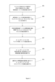
図2は、例によるホログラフィックRLSAアレイについてのスロットアクティブ化構成のセットを生成するための方法のフローチャートである。上述されたように、RLSAアレイは、予め構成されたスロットパターンを定義する複数のスロットを備え、各スロットアクティブ化構成は、信号がアレイによって放出されるべきビームパターンを定義する。ブロック201では、アンテナに印加されるべき信号が存在する場合の複数のスロット間の相互結合についての測定値が生成される。例では、測定値は、アンテナについての散乱行列(s行列)を定義する散乱パラメータのセットを備える。散乱行列は、例えば50オームの抵抗器などの抵抗素子を備えるアンテナの全てのスロット及び全てのフィード上のポートを考慮することによって計算されることができる。抵抗素子を通過する電流を計算して、アレイについてのsパラメータを得ることができ、それによって、アレイ中の各ポートから全ての他のポートへの結合の特徴付けを可能にする。
2 is a flow chart of a method for generating a set of slot activation configurations for a holographic RLSA array according to an example. As described above, the RLSA array comprises a number of slots that define a preconfigured slot pattern, with each slot activation configuration defining a beam pattern in which a signal is to be emitted by the array. In
ブロック203では、相互結合についての測定値を使用して、アレイについてのインピーダンスパラメータのセットを計算する。インピーダンス行列は、静電容量がアレイの幾何学的形状に追加されることを可能にし、それによって、スロットの共振周波数の同調を可能にする。z行列のzパラメータは、一般に、以下の式によってそのsパラメータに関連付けられる:
In
![]()
![]()
ここで、1Nは単位行列であり、 where 1N is the identity matrix,
![]()
![]()
は、各ポートにおける特性インピーダンスの平方根をその非ゼロ要素として有する対角行列である。 is a diagonal matrix with the square root of the characteristic impedance at each port as its nonzero elements.
ブロック205では、複数のスロットのうちの少なくとも1つの共振は、スロットの両端に提供される、例えばバラクタダイオードなどの可変性静電容量デバイスの静電容量の値を調整又は選択することによって制御されるか又は変化させられる。即ち、スロットの共振周波数は、スロットの静電容量を変化させ、ビームパターンについてのアンテナ利得についての値を測定し(ブロック207)、ビームパターンについての利得の最も高い測定値をもたらす静電容量の最終値を選択する(ブロック209)ことによって同調される。アレイについてのビームパターンは、スロットの活動の状態に応じて変化するので、1つ以上のスロットが共振する程度を変化させるために、1つ以上のスロットについての静電容量の様々な組み合わせを循環させることによって、様々なビームパターンが生成されることができる。
In
ブロック211では、ビームパターンについてのスロットアクティブ化構成が、選択された静電容量の最終値に基づいて選択される。即ち、アレイについての所望のビームパターンが与えられると、スロットアクティブ化構成は、オン又はオフに切り替えられる(又は放出の半アクティブ状態にある)べきスロットのセットを定義する。スロットの放出状態は、例では、当該スロットについての容量性リアクタンスによって決定される。そのような値は、スロットが放射している状態、最大値で放射している状態、又はこれらの極値間のどこかにある状態になることを効果的に防止するために選択されることができる。それ故に、スロットの共振周波数を同調する際に、アレイのスロットに関連付けられた静電容量値の所与の組み合わせについてのアンテナ利得についての値は、それらの様々な活動状態におけるスロット間の結合に起因してビームパターンを生じさせる。例えば遺伝的アルゴリズムを使用して、アレイのスロットについての静電容量の様々な組み合わせを循環させることによって、構成のセットが構築されることができ、構成のセットの各々は、所与のビームパターンにマッピングされ、それらのうちのいくつかは、対象となるものであり、それらのうちの他のものは、対象とはならない場合があり得る。このことから、スロットの状態(例えば、オン、オフ、半アクティブ、など)を修正するためにスロットの静電容量を変化させることによって、望ましい又は所望のビームパターンをもたらす構成のピクチャが構築されることができる。
In
例によると、スロットは、例えば離散値であり得る複数の値のうちの1つから選択された静電容量を印加することによって、オン若しくはオフに切り替えられることができるか、又は半アクティブ状態で提供されることができる。それ故に、アレイによって放出されるべき所望のビームパターンは、スロットのある割合が第1のレベルで放射しており、スロットのある割合が第2のレベルで放射しており、以下同様であるスロットアクティブ化構成に関連し得る。第1のレベルは、スロットが効果的にオフであることに対応することができ、その一方で、第2のレベルは、スロットが効果的にオンであり、共振又は共振付近で放射することに対応することができる。これらの状態間では、スロットが共振未満で放射しているが「オフ」ではない、様々な他のレベルのスロット活動が、1つ以上のスロットについての静電容量の優勢な値に応じて提供されることができる。 According to an example, the slots can be switched on or off or provided in a semi-active state by applying a capacitance selected from one of a plurality of values, which may be, for example, discrete values. Thus, a desired beam pattern to be emitted by the array may be associated with a slot activation configuration in which a certain percentage of the slots are radiating at a first level, a certain percentage of the slots are radiating at a second level, and so on. The first level may correspond to the slots being effectively off, while the second level may correspond to the slots being effectively on and radiating at or near resonance. In between these states, various other levels of slot activity, in which the slots are radiating below resonance but are not "off", may be provided depending on the prevailing value of capacitance for one or more slots.
本開示は、本開示の例による方法、デバイス、装置、及びシステムのフローチャート及び/又はブロック図を参照して説明される。説明されるフロー図は、特定の実行順序を示し得るが、実行順序は、図示されている実行順序とは異なり得る。あるフローチャートに関連して説明されたブロックは、別のフローチャートのブロックと組み合わせられ得る。いくつかの例では、フロー図のいくつかのブロックは必要でない場合があり、及び/又は追加のブロックが追加され得る。フローチャート及び/又はブロック図における各フロー及び/又はブロック、並びにフローチャート及び/又はブロック図におけるフロー及び/又は図の組み合わせは、機械可読命令によって実現されることができることを理解されたい。 The present disclosure is described with reference to flowcharts and/or block diagrams of methods, devices, apparatus, and systems according to examples of the disclosure. Although the described flow diagrams may show a particular order of execution, the order of execution may differ from the order of execution depicted. Blocks described in connection with one flowchart may be combined with blocks of another flowchart. In some examples, some blocks of a flow diagram may not be required and/or additional blocks may be added. It should be understood that each flow and/or block in the flowchart and/or block diagram, and combinations of flows and/or diagrams in the flowchart and/or block diagram, may be implemented by machine-readable instructions.
機械可読命令は、例えば、汎用コンピュータ、スマートデバイス、例えば、スマートフォンなどのユーザ機器、専用コンピュータ、組み込みプロセッサ、又は本説明及び図に説明された機能を実現するための他のプログラマブルデータ処理デバイスのプロセッサなどの機械によって実行され得る。特に、プロセッサ又は処理装置は、機械可読命令を実行し得る。このことから、装置のモジュール(例えば、s行列をz行列に変換し、その逆も同様に行うための変換器を実装するモジュール)は、メモリ中に記憶された機械可読命令を実行するプロセッサ、又は論理回路中に埋め込まれた命令に従って動作するプロセッサによって実装され得る。「プロセッサ」という用語は、CPU、処理ユニット、ASIC、論理ユニット、又はプログラマブルゲートセット、等を含むように広く解釈されるべきである。方法及びモジュールは全て、単一のプロセッサによって実行され得るか、又はいくつかのプロセッサ間で分割され得る。 The machine-readable instructions may be executed by a machine, such as a general-purpose computer, a processor of a smart device, e.g., a user equipment such as a smartphone, a dedicated computer, an embedded processor, or other programmable data processing device to realize the functions described in this description and in the figures. In particular, a processor or processing device may execute the machine-readable instructions. From this, a module of the device (e.g., a module implementing a converter for converting an s-matrix to a z-matrix and vice versa) may be implemented by a processor that executes machine-readable instructions stored in a memory, or a processor that operates according to instructions embedded in a logic circuit. The term "processor" should be interpreted broadly to include a CPU, a processing unit, an ASIC, a logic unit, or a set of programmable gates, etc. All the methods and modules may be executed by a single processor or may be divided among several processors.
そのような機械可読命令はまた、コンピュータ又は他のプログラマブルデータ処理デバイスを特定のモードで動作するように誘導することができるコンピュータ可読記憶装置中に記憶され得る。例えば、命令は、プロセッサによって実行可能な命令で符号化された非一時的コンピュータ可読記憶媒体上に提供され得る。 Such machine-readable instructions may also be stored in a computer-readable storage device that can direct a computer or other programmable data processing device to operate in a particular mode. For example, the instructions may be provided on a non-transitory computer-readable storage medium encoded with instructions executable by a processor.
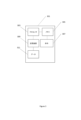
図3は、例による機械の概略図である。図3の例では、機械301は、プロセッサ303と、プロセッサ303によって実行可能な命令307を記憶するためのメモリ305とを備える。スロットアクティブ化構成、sパラメータ及び/又は行列、zパラメータ及び/又は行列、並びに静電容量値のセットのうちの任意の1つ以上を表すデータ311を記憶するために使用されることができる記憶装置309。プロセッサ303によって実行可能な命令307は、機械に、アレイについての散乱パラメータのセットを使用してアレイについてのインピーダンス行列を生成することと、容量性リアクタンスを使用してスロットの共振周波数を同調して、それによって、アレイについての更新されたインピーダンス行列を生成することと、更新されたインピーダンス行列を使用して複数のスロットの周囲の電流のそれぞれの測定値を計算することと、電流の測定値及びインピーダンス行列を使用して複数のスロットの両端の電圧のそれぞれの測定値を計算することと、更新されたインピーダンス行列を散乱パラメータの更新されたセットに変換することと、散乱パラメータの更新されたセット及び電圧の測定値を使用して、アンテナについての放射パターンを計算することとを行わせることができる。
3 is a schematic diagram of a machine according to an example. In the example of FIG. 3, the
例によると、アレイのスロット間の相互結合についての測定値は、アレイの幾何学的形状を特徴付けるs行列を備える。s行列は、対象のアレイの幾何学的形状のあらゆる点にポートを適用することによって生成されることができ、あらゆる点において、ポートは、電圧及び電流が測定されることができる抵抗器を備えることができる。アレイについて計算されたs行列は、上述されたようにインピーダンス行列(z行列)に変換されることができる。インピーダンス行列[Z]が与えられると、容量性リアクタンスを各スロットに印加して、負荷インピーダンス行列[Zloaded]を提供することができ、そのため: By way of example, measurements of mutual coupling between slots of an array comprise an s-matrix that characterizes the geometry of the array. The s-matrix can be generated by applying a port to every point of the geometry of the array of interest, where the port can comprise a resistor at which voltage and current can be measured. The s-matrix calculated for the array can be converted to an impedance matrix (z-matrix) as described above. Given an impedance matrix [Z], a capacitive reactance can be applied to each slot to provide a load impedance matrix [ Zloaded ], such that:
![]()
![]()
であり、ここで、[C]は、以下の式によって与えられる(容量性)リアクタンスの1Dアレイである: where [C] is a 1D array of (capacitive) reactances given by:

従って、静電容量が追加された新しいインピーダンス行列が存在し、そのため: Therefore, there is a new impedance matrix with the capacitance added, so:

新しいZ行列([Zloaded])は、アレイの無負荷同軸ポートのSパラメータが調べられることを可能にするために、及び/又はスロット素子上の励振[Vexcite]の計算を可能にするために、Sパラメータ行列に変換されることができる。例では、[Zloaded]は、オームの法則を使用して各スロットの周囲の電流を計算するために使用されることができ、ここで、[V]は、印加される電圧の1Dアレイである。例では、1Vが、第1の素子(同軸フィードポートを表す)に印加されることができ、全ての他の電圧は、0に設定されることができる。即ち: The new Z-matrix ([Z loaded ]) can be converted to an S-parameter matrix to allow the S-parameters of the unloaded coaxial ports of the array to be examined and/or to allow the calculation of the excitation [V excite ] on the slot elements. In an example, [Z loaded ] can be used to calculate the current around each slot using Ohm's law, where [V] is a 1D array of applied voltages. In an example, 1V can be applied to the first element (representing the coaxial feed port) and all other voltages can be set to 0, i.e.:
![]()
![]()
それ故に、[Iloaded]は、次いで、以下の式に従ってスロットの両端の電圧[Vslot]を計算するために使用されることができる: Therefore, [I loaded ] can then be used to calculate the voltage across the slot [V slot ] according to the following formula:
![]()
![]()
ここで、[Z]は、元の(無負荷)インピーダンス行列である。[Vslot]を使用して、アレイファクタ(AF:array factor)計算を実行して、以下の式に従ってアンテナ放射パターンを決定することができる: where Z is the original (unloaded) impedance matrix. Using V slot , an array factor (AF) calculation can be performed to determine the antenna radiation pattern according to the following formula:

ここで、Nは、 Here, N is,
![]()
![]()
に位置する放射器のアレイである。anは、複素数値の励振係数であり、 a n are complex-valued excitation coefficients,
![]()
![]()
は、方向単位ベクトルである。 is the directional unit vector.
従って、例によると、無負荷フィードポートのSパラメータ及びアンテナ放射パターンが、計算されることができる。例えば遺伝的アルゴリズムなどの最適化ルーチンを用いて、これらの変数を最適化することができる。例では、最適化は、入力ポートから反射される電力を最小化すること、及び/又は第2の無負荷同軸ポートに送信される電力を最小化することを目的とすることができる(電力損失は放射されると仮定される)。最適化は、所与の方向に放射される電力を最大化し、また、全ての他の方向に放射される電力を最小化することを目的とすることができる。軸比、交差偏波など、アンテナパターンに関する他のパラメータが含まれることができる。 Thus, by way of example, the S-parameters of the unloaded feed port and the antenna radiation pattern can be calculated. These variables can be optimized using an optimization routine, such as a genetic algorithm. In an example, the optimization can aim to minimize the power reflected from the input port and/or the power transmitted to the second unloaded coaxial port (power losses are assumed to be radiated). The optimization can aim to maximize the power radiated in a given direction and also minimize the power radiated in all other directions. Other parameters related to the antenna pattern can be included, such as axial ratio, cross polarization, etc.
例によると、アンテナパターン及びsパラメータは、スロット素子上の静電容量の初期推定値を用いて予測されることができる。これに続いて、上記で説明されたように最適化が実行されることができ、これは、いくつかのアンテナビーム指向角度に対して繰り返すことができる。 By way of example, the antenna pattern and s-parameters can be predicted using an initial estimate of the capacitance on the slot elements. Following this, an optimization can be performed as described above, which can be repeated for several antenna beam pointing angles.
それ故に、機械は、予め構成されたスロットパターンを定義する複数のスロットを備えるホログラフィックラジアルラインスロットアンテナアレイについてのスロットアクティブ化構成のセットを生成するための方法を実施することができ、各スロットアクティブ化構成は、アンテナによって放出されるべき信号についてのビームパターンを定義する。 The machine can therefore perform a method for generating a set of slot activation configurations for a holographic radial line slot antenna array comprising a plurality of slots defining preconfigured slot patterns, each slot activation configuration defining a beam pattern for a signal to be emitted by the antenna.
そのような機械可読命令はまた、コンピュータ又は他のプログラマブルデータ処理デバイス上にロードされ得、そのため、コンピュータ又は他のプログラマブルデータ処理デバイスは、一連の動作を実行してコンピュータ実装処理を生成し、このことから、コンピュータ又は他のプログラマブルデバイス上で実行される命令は、フローチャート中のフロー(複数可)及び/又はブロック図中のブロック(複数可)によって指定される機能を実現するための動作を提供する。 Such machine-readable instructions may also be loaded onto a computer or other programmable data processing device so that the computer or other programmable data processing device executes a sequence of operations to generate a computer-implemented process, such that the instructions executing on the computer or other programmable device provide operations for realizing the functions specified by the flow(s) in the flowcharts and/or the block(s) in the block diagrams.
更に、本明細書での教示は、非一時的機械可読記憶媒体などのコンピュータ又はソフトウェア製品の形態で実装され得、コンピュータソフトウェア又は製品は、記憶媒体中に記憶され、コンピュータデバイスに本開示の例に記載された方法を実施させるための複数の命令、例えば機械可読命令を備える。 Furthermore, the teachings herein may be implemented in the form of a computer or software product, such as a non-transitory machine-readable storage medium, the computer software or product comprising a plurality of instructions, e.g., machine-readable instructions, stored in the storage medium for causing a computing device to perform the methods described in the examples of this disclosure.
いくつかの例では、いくつかの方法は、クラウドコンピューティング又はネットワークベースの環境で実行されることができる。クラウドコンピューティング環境は、インターネットを介して様々なサービス及びアプリケーションを提供し得る。これらのクラウドベースのサービス(例えば、サービスとしてのソフトウェア、サービスとしてのプラットフォーム、サービスとしてのインフラストラクチャ、等)は、ウェブブラウザ又は他のリモートインタフェースを通してアクセス可能であり得る。本明細書で説明された様々な機能は、リモートデスクトップ環境又は任意の他のクラウドベースのコンピューティング環境を通じて提供され得る。 In some examples, some methods may be performed in a cloud computing or network-based environment. A cloud computing environment may provide various services and applications over the Internet. These cloud-based services (e.g., software as a service, platform as a service, infrastructure as a service, etc.) may be accessible through a web browser or other remote interface. Various functions described herein may be provided through a remote desktop environment or any other cloud-based computing environment.
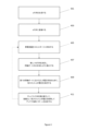
図4は、例による方法の概略図である。ブロック401では、対象の所与のRLSAアレイの幾何学的形状に対して、上記で説明されたようにs行列が生成される。ブロック403では、問題のアレイについてのブロック401からのS行列は、上記で説明されたようにZ行列に変換され、ブロック405では、アレイのスロットを同調するために、静電容量がスロットポート中に印加される。上記で説明されたように、同調は、スロットが、印加される静電容量の値に応じて、共振で、効果的にオフで、又はある程度中間で動作するように整えられることができる。調査中の所与のビームパターンに対して、スロットは、従って、複数のレジームのうちのいずれか1つで動作することができ、それによって、複雑なビームパターン及びビームステアリングが提供されることを可能にする。ブロック407では、上記で説明されたように、新しいS行列が決定され、同軸ポートのみを含むように縮小される。即ち、例では、負荷Z行列は、Sパラメータ行列に変換されて戻り、無負荷同軸ポートのSパラメータが何であるかについての調査を可能にすることができる。ブロック409では、入力電圧がアレイの第1の同軸ポートに(即ち、アレイのフィードに)印加されるとき、各スロット上の電圧が決定される。例では、この入力電圧は、1Vであり得る。ブロック411では、アレイファクタ計算を実行して、励振として各スロット上の電圧を使用してアンテナ放射パターンを決定することができる。
4 is a schematic diagram of a method according to an example. In
様々な実施形態が、十分に機能的なコンピューティングシステムの文脈で本明細書で説明及び/又は例示されているが、これらの例証的な実施形態のうちの1つ以上は、実際に配布を実施するために使用される特定のタイプのコンピュータ可読記憶媒体にかかわらず、様々な形態のプログラム製品として配布され得る。本明細書で開示される実施形態はまた、ある特定のタスクを実行するソフトウェアモジュールを使用して実装され得る。これらのソフトウェアモジュールは、コンピュータ可読記憶媒体上又はコンピューティングシステム中に記憶され得るスクリプト、バッチ、又は他の実行可能ファイルを含み得る。いくつかの実施形態では、これらのソフトウェアモジュールは、本明細書で開示される例証的な実施形態のうちの1つ以上を実行するようにコンピューティングシステムを構成し得る。加えて、本明細書で説明されるモジュールのうちの1つ以上は、データ、物理的デバイス、及び/又は物理的デバイスの表現をある形態から別の形態に変換し得る。 Although various embodiments are described and/or illustrated herein in the context of a fully functional computing system, one or more of these illustrative embodiments may be distributed as a program product in various forms, regardless of the particular type of computer-readable storage medium actually used to effect the distribution. The embodiments disclosed herein may also be implemented using software modules that perform certain tasks. These software modules may include scripts, batches, or other executable files that may be stored on a computer-readable storage medium or in the computing system. In some embodiments, these software modules may configure the computing system to execute one or more of the illustrative embodiments disclosed herein. In addition, one or more of the modules described herein may convert data, physical devices, and/or representations of physical devices from one form to another.
先の説明は、当業者が本明細書で開示された例証的な実施形態の様々な態様を最も良く利用することを可能にするために提供された。この例証的な説明は、網羅的であること、又は開示された任意の厳密な形態に限定されることを意図されない。本開示の趣旨及び範囲から逸脱することなく、多くの修正形態及び変形形態が可能である。本明細書で開示された実施形態は、全ての点で例示的であるとみなされるべきであり、限定的であるとみなされるべきではない。本開示の範囲を決定する際には、添付の特許請求の範囲及びそれらの均等物への参照が成されるべきである。
以下に、出願当初の特許請求の範囲に記載の事項を、そのまま、付記しておく。
[C1]
予め構成されたスロットパターンを定義する複数のスロットを備えるホログラフィックラジアルラインスロットアンテナアレイについてのスロットアクティブ化構成のセットを生成するための方法であって、各スロットアクティブ化構成は、前記アンテナによって放出されるべき信号についてのビームパターンを定義し、前記方法は、
前記アンテナに印加されるべき信号が存在する場合の前記複数のスロット間の相互結合についての測定値を生成することと、ここで、前記測定値は、前記アンテナについての散乱行列を定義する散乱パラメータのセットを備え、
相互結合についての前記測定値を使用して、前記アレイについてのインピーダンスパラメータのセットを生成することと、
前記スロットの両端に提供される可変性静電容量デバイスの静電容量の値を調整することによって前記複数のスロットのうちの少なくとも1つの共振を制御することと、
前記静電容量の値に関連付けられたビームパターンのアンテナ利得についての値を測定することと、
前記ビームパターンについての利得の最も高い測定値をもたらす静電容量の最終値を選択することと、
選択された前記静電容量の最終値に基づいて前記ビームパターンについてのスロットアクティブ化構成を選択することと
を備える、方法。
[C2]
前記アンテナの放射電力についての値を測定すること
を更に備える、C1に記載の方法。
[C3]
前記アンテナについてのピーク利得の方向の電力についての値を測定すること
を更に備える、C1又は2に記載の方法。
[C4]
前記静電容量の値が存在する場合の前記複数のスロット間の相互結合についての更新された測定値を生成すること
を更に備える、C1~3のいずれか一項に記載の方法。
[C5]
前記複数のスロットのポートの両端に論理的に配設された抵抗素子を通って流れる電流のそれぞれの測定値を計算することによって相互結合についての前記測定値を決定すること
を更に備える、C1~4のいずれか一項に記載の方法。
[C6]
可変性静電容量デバイスの静電容量の値を調整することは、前記複数のスロットについての無効静電容量のそれぞれの値を調節することを備える、C1~5のいずれか一項に記載の方法。
[C7]
前記アレイについての前記インピーダンスパラメータのセットを前記静電容量の値が存在する場合の前記スロット間の相互結合についての更新された測定値に変換すること
を更に備える、C1~6のいずれか一項に記載の方法。
[C8]
前記複数のスロットの励振についてのそれぞれの測定値を計算すること
を更に備える、C7に記載の方法。
[C9]
容量性リアクタンスについての複数の離散値のうちの1つを使用して、前記スロットの両端に提供される可変性静電容量デバイスの静電容量の値を調整することによって前記複数のスロットのうちの少なくとも1つの共振を制御すること
を更に備える、C1~8のいずれか一項に記載の方法。
[C10]
予め構成されたスロットパターンを定義する複数のスロットを備えるホログラフィックラジアルラインスロットアンテナアレイについてのスロットアクティブ化構成のセットを生成するための命令で符号化された非一時的機械可読記憶媒体であって、各スロットアクティブ化構成は、前記アンテナによって放出されるべき信号についてのビームパターンを定義し、前記命令は、機械のプロセッサによって実行可能であって、それによって、前記機械に、
前記アレイについての散乱パラメータのセットを使用して前記アレイについてのインピーダンス行列を生成することと、
容量性リアクタンスを使用してスロットの共振周波数を同調して、それによって、前記アレイについての更新されたインピーダンス行列を生成することと、
前記更新されたインピーダンス行列を使用して前記複数のスロットの周囲の電流のそれぞれの測定値を計算することと、
前記電流の測定値及び前記インピーダンス行列を使用して前記複数のスロットの両端の電圧のそれぞれの測定値を計算することと、
前記更新されたインピーダンス行列を散乱パラメータの更新されたセットに変換することと、
前記散乱パラメータの更新されたセット及び前記電圧の測定値を使用して、前記アンテナについての放射パターンを計算することと
を行わせる、記憶媒体。
[C11]
前記機械に、
前記アレイの入力ポートから反射された電力を最小化するために、容量性リアクタンスの複数の異なる組み合わせを使用して前記共振周波数を最適化させるための命令を更に備える、C10に記載の記憶媒体。
[C12]
前記機械に、
前記アレイの無負荷同軸ポートに送信される電力を最小化するために、容量性リアクタンスの複数の異なる組み合わせを使用して前記共振周波数を最適化させるための命令を更に備える、C10又は11に記載の記憶媒体。
[C13]
前記機械に、
選択された方向に放射される電力を最大化するために、容量性リアクタンスの複数の異なる組み合わせを使用して前記共振周波数を最適化させるための命令を更に備える、C10~12のいずれか一項に記載の記憶媒体。
[C14]
前記機械に、
スロットアクティブ化構成のセットを生成させるための命令を更に備え、各スロットアクティブ化構成は、前記アレイについての所与のビームパターンのために前記複数のスロットの各々についての容量性リアクタンスを定義する、C10~13のいずれか一項に記載の記憶媒体。
[C15]
前記機械に、
前記容量性リアクタンスについての複数の離散値のうちの1つを使用してスロットの前記共振周波数を同調させるための命令を更に備える、C9~14のいずれか一項に記載の記憶媒体。
The preceding description is provided to enable those skilled in the art to best utilize various aspects of the exemplary embodiments disclosed herein. This exemplary description is not intended to be exhaustive or to be limited to any precise form disclosed. Many modifications and variations are possible without departing from the spirit and scope of the present disclosure. The embodiments disclosed herein should be considered in all respects as illustrative and not restrictive. In determining the scope of the present disclosure, reference should be made to the appended claims and their equivalents.
The following is a summary of the claims as originally filed:
[C1]
1. A method for generating a set of slot activation configurations for a holographic radial line slot antenna array comprising a plurality of slots defining preconfigured slot patterns, each slot activation configuration defining a beam pattern for a signal to be emitted by the antenna, the method comprising:
generating a measurement of mutual coupling between the plurality of slots in the presence of a signal to be applied to the antenna, wherein the measurement comprises a set of scattering parameters defining a scattering matrix for the antenna;
generating a set of impedance parameters for the array using the measurements of mutual coupling; and
controlling the resonance of at least one of the plurality of slots by adjusting a capacitance value of a variable capacitance device provided across the slot;
measuring a value for an antenna gain of a beam pattern associated with said capacitance value;
selecting a final value of capacitance that results in the highest measured gain for said beam pattern;
selecting a slot activation configuration for the beam pattern based on the selected final capacitance value;
A method comprising:
[C2]
Measuring a value for the radiated power of said antenna.
The method of claim 1, further comprising:
[C3]
Measuring a value for power in a direction of peak gain for said antenna.
The method of any one of claims 1 to 2, further comprising:
[C4]
generating an updated measurement of mutual coupling between the plurality of slots when the capacitance values are present;
The method of any one of C1 to C3, further comprising:
[C5]
determining said measurements of mutual coupling by calculating respective measurements of current flowing through resistive elements logically disposed across ports of said plurality of slots;
The method of any one of C1 to C4, further comprising:
[C6]
The method of any one of C1-5, wherein adjusting the capacitance value of the variable capacitance device comprises adjusting respective values of reactive capacitance for the plurality of slots.
[C7]
converting the set of impedance parameters for the array into an updated measurement of mutual coupling between the slots when the capacitance values are present;
The method of any one of C1 to C6, further comprising:
[C8]
calculating respective measurements for excitation of said plurality of slots;
The method of C7, further comprising:
[C9]
controlling resonance of at least one of the plurality of slots by adjusting a value of capacitance of a variable capacitance device provided across the slot using one of a plurality of discrete values for capacitive reactance.
The method of any one of C1 to C8, further comprising:
[C10]
A non-transitory machine-readable storage medium encoded with instructions for generating a set of slot activation configurations for a holographic radial line slot antenna array comprising a plurality of slots defining preconfigured slot patterns, each slot activation configuration defining a beam pattern for a signal to be emitted by the antenna, the instructions being executable by a processor of a machine, thereby causing the machine to:
generating an impedance matrix for the array using a set of scattering parameters for the array;
tuning the resonant frequencies of the slots using capacitive reactance to thereby generate an updated impedance matrix for the array;
calculating respective measurements of currents around the plurality of slots using the updated impedance matrix;
calculating respective measurements of voltage across the plurality of slots using the current measurements and the impedance matrix;
converting the updated impedance matrix into an updated set of scattering parameters;
calculating a radiation pattern for the antenna using the updated set of scattering parameters and the voltage measurements; and
A storage medium that causes the
[C11]
The machine,
The storage medium of C10, further comprising instructions for optimizing the resonant frequency using a plurality of different combinations of capacitive reactance to minimize power reflected from an input port of the array.
[C12]
The machine,
12. The storage medium of claim 10, further comprising instructions for optimizing the resonant frequency using a plurality of different combinations of capacitive reactance to minimize power transmitted to an unloaded coaxial port of the array.
[C13]
The machine,
The storage medium of any one of C10 to C12, further comprising instructions for optimizing the resonant frequency using a plurality of different combinations of capacitive reactances to maximize power radiated in a selected direction.
[C14]
The machine,
The storage medium of any one of C10 to C13, further comprising instructions for generating a set of slot activation configurations, each slot activation configuration defining a capacitive reactance for each of the plurality of slots for a given beam pattern for the array.
[C15]
The machine,
The storage medium of any one of C9 to C14, further comprising instructions for tuning the resonant frequency of a slot using one of a plurality of discrete values for the capacitive reactance.
Claims (15)
前記アンテナに印加されるべき信号が存在する場合の前記複数のスロット間の相互結合についての測定値を生成することと、ここで、前記測定値は、前記アンテナについての散乱行列を定義する散乱パラメータのセットを備え、
相互結合についての前記測定値を使用して、前記アレイについてのインピーダンスパラメータのセットを生成することと、
前記スロットの両端に提供される可変性静電容量デバイスの静電容量の値を調整することによって前記複数のスロットのうちの少なくとも1つの共振を制御することと、
前記静電容量の値に関連付けられたビームパターンのアンテナ利得についての値を測定することと、
前記ビームパターンについての利得の最も高い測定値をもたらす静電容量の最終値を選択することと、
選択された前記静電容量の最終値に基づいて前記ビームパターンについてのスロットアクティブ化構成を選択することと
を備える、方法。 1. A method for generating a set of slot activation configurations for a holographic radial line slot antenna array comprising a plurality of slots defining preconfigured slot patterns, each slot activation configuration defining a beam pattern for a signal to be emitted by the antenna, the method comprising:
generating a measurement of mutual coupling between the plurality of slots in the presence of a signal to be applied to the antenna, wherein the measurement comprises a set of scattering parameters defining a scattering matrix for the antenna;
generating a set of impedance parameters for the array using the measurements of mutual coupling; and
controlling the resonance of at least one of the plurality of slots by adjusting a capacitance value of a variable capacitance device provided across the slot;
measuring a value for an antenna gain of a beam pattern associated with said capacitance value;
selecting a final value of capacitance that results in the highest measured gain for said beam pattern;
selecting a slot activation configuration for the beam pattern based on the selected final capacitance value.
を更に備える、請求項1に記載の方法。 The method of claim 1 , further comprising: measuring a value for the radiated power of the antenna.
を更に備える、請求項1に記載の方法。 The method of claim 1 , further comprising: measuring a value for power in a peak gain direction for the antenna.
を更に備える、請求項1に記載の方法。 The method of claim 1 , further comprising: generating an updated measurement of mutual coupling between the plurality of slots when the capacitance value is present.
を更に備える、請求項1に記載の方法。 2. The method of claim 1, further comprising: determining the measurements of mutual coupling by calculating respective measurements of current flowing through resistive elements logically disposed across ports of the plurality of slots .
を更に備える、請求項1に記載の方法。 The method of claim 1 , further comprising: converting the set of impedance parameters for the array into an updated measurement of mutual coupling between the slots when the capacitance value is present.
を更に備える、請求項7に記載の方法。 The method of claim 7 , further comprising: calculating respective measurements for the excitation of the plurality of slots.
を更に備える、請求項1に記載の方法。 10. The method of claim 1, further comprising: controlling resonance of at least one of the plurality of slots by adjusting a value of a capacitance of a variable capacitance device provided across the slot using one of a plurality of discrete values for capacitive reactance.
前記アレイについての散乱パラメータのセットを使用して前記アレイについてのインピーダンス行列を生成することと、
容量性リアクタンスを使用してスロットの共振周波数を同調して、それによって、前記アレイについての更新されたインピーダンス行列を生成することと、
前記更新されたインピーダンス行列を使用して前記複数のスロットの周囲の電流のそれぞれの測定値を計算することと、
前記電流の測定値及び前記インピーダンス行列を使用して前記複数のスロットの両端の電圧のそれぞれの測定値を計算することと、
前記更新されたインピーダンス行列を散乱パラメータの更新されたセットに変換することと、
前記散乱パラメータの更新されたセット及び前記電圧の測定値を使用して、前記アンテナについての放射パターンを計算することと
を行わせる、記憶媒体。 A non-transitory machine-readable storage medium encoded with instructions for generating a set of slot activation configurations for a holographic radial line slot antenna array comprising a plurality of slots defining preconfigured slot patterns, each slot activation configuration defining a beam pattern for a signal to be emitted by the antenna, the instructions being executable by a processor of a machine, thereby causing the machine to:
generating an impedance matrix for the array using a set of scattering parameters for the array;
tuning the resonant frequencies of the slots using capacitive reactance to thereby generate an updated impedance matrix for the array;
calculating respective measurements of currents around the plurality of slots using the updated impedance matrix;
calculating respective measurements of voltage across the plurality of slots using the current measurements and the impedance matrix;
converting the updated impedance matrix into an updated set of scattering parameters;
and calculating a radiation pattern for the antenna using the updated set of scattering parameters and the voltage measurements.
前記アレイの入力ポートから反射された電力を最小化するために、容量性リアクタンスの複数の異なる組み合わせを使用して前記共振周波数を最適化させるための命令を更に備える、請求項10に記載の記憶媒体。 The machine,
11. The storage medium of claim 10, further comprising instructions for optimizing the resonant frequency using a plurality of different combinations of capacitive reactances to minimize power reflected from an input port of the array.
前記アレイの無負荷同軸ポートに送信される電力を最小化するために、容量性リアクタンスの複数の異なる組み合わせを使用して前記共振周波数を最適化させるための命令を更に備える、請求項10に記載の記憶媒体。 The machine,
11. The storage medium of claim 10 , further comprising instructions for optimizing the resonant frequency using a plurality of different combinations of capacitive reactances to minimize power transmitted to an unloaded coaxial port of the array.
選択された方向に放射される電力を最大化するために、容量性リアクタンスの複数の異なる組み合わせを使用して前記共振周波数を最適化させるための命令を更に備える、請求項10に記載の記憶媒体。 The machine,
11. The storage medium of claim 10 , further comprising instructions for optimizing the resonant frequency using a plurality of different combinations of capacitive reactances to maximize power radiated in a selected direction.
スロットアクティブ化構成のセットを生成させるための命令を更に備え、各スロットアクティブ化構成は、前記アレイについての所与のビームパターンのために前記複数のスロットの各々についての容量性リアクタンスを定義する、請求項10に記載の記憶媒体。 The machine,
11. The storage medium of claim 10, further comprising instructions for generating a set of slot activation configurations, each slot activation configuration defining a capacitive reactance for each of the plurality of slots for a given beam pattern for the array.
前記容量性リアクタンスについての複数の離散値のうちの1つを使用してスロットの前記共振周波数を同調させるための命令を更に備える、請求項10に記載の記憶媒体。 The machine,
11. The storage medium of claim 10 , further comprising instructions for tuning the resonant frequency of a slot using one of a plurality of discrete values for the capacitive reactance.
Applications Claiming Priority (5)
| Application Number | Priority Date | Filing Date | Title |
|---|---|---|---|
| EP21275147.3A EP4164062A1 (en) | 2021-10-08 | 2021-10-08 | Radial line slot antenna array |
| GB2114431.6 | 2021-10-08 | ||
| GB2114431.6A GB2611568A (en) | 2021-10-08 | 2021-10-08 | Radial line slot antenna arrays |
| EP21275147.3 | 2021-10-08 | ||
| PCT/GB2022/052529 WO2023057762A1 (en) | 2021-10-08 | 2022-10-06 | Radial line slot antenna arrays |
Publications (2)
| Publication Number | Publication Date |
|---|---|
| JP2024533854A JP2024533854A (en) | 2024-09-12 |
| JP7686885B2 true JP7686885B2 (en) | 2025-06-02 |
Family
ID=83688697
Family Applications (1)
| Application Number | Title | Priority Date | Filing Date |
|---|---|---|---|
| JP2024521181A Active JP7686885B2 (en) | 2021-10-08 | 2022-10-06 | Radial Line Slot Antenna Array |
Country Status (5)
| Country | Link |
|---|---|
| US (1) | US20240429617A1 (en) |
| EP (1) | EP4413636A1 (en) |
| JP (1) | JP7686885B2 (en) |
| AU (1) | AU2022360283A1 (en) |
| WO (1) | WO2023057762A1 (en) |
Citations (3)
| Publication number | Priority date | Publication date | Assignee | Title |
|---|---|---|---|---|
| US20150288063A1 (en) | 2014-04-07 | 2015-10-08 | Mikala C. Johnson | Beam shaping for reconfigurable holographic antennas |
| US20170301475A1 (en) | 2016-04-15 | 2017-10-19 | Kymeta Corporation | Rf resonators with tunable capacitor and methods for fabricating the same |
| JP2019533925A (en) | 2016-09-14 | 2019-11-21 | カイメタ コーポレイション | Impedance matching for aperture antennas |
Family Cites Families (1)
| Publication number | Priority date | Publication date | Assignee | Title |
|---|---|---|---|---|
| US10454184B2 (en) * | 2017-01-27 | 2019-10-22 | Huawei Technologies Co., Ltd. | Reconfigurable radial-line slot antenna array |
-
2022
- 2022-10-06 JP JP2024521181A patent/JP7686885B2/en active Active
- 2022-10-06 WO PCT/GB2022/052529 patent/WO2023057762A1/en not_active Ceased
- 2022-10-06 US US18/699,287 patent/US20240429617A1/en active Pending
- 2022-10-06 EP EP22786416.2A patent/EP4413636A1/en active Pending
- 2022-10-06 AU AU2022360283A patent/AU2022360283A1/en active Pending
Patent Citations (3)
| Publication number | Priority date | Publication date | Assignee | Title |
|---|---|---|---|---|
| US20150288063A1 (en) | 2014-04-07 | 2015-10-08 | Mikala C. Johnson | Beam shaping for reconfigurable holographic antennas |
| US20170301475A1 (en) | 2016-04-15 | 2017-10-19 | Kymeta Corporation | Rf resonators with tunable capacitor and methods for fabricating the same |
| JP2019533925A (en) | 2016-09-14 | 2019-11-21 | カイメタ コーポレイション | Impedance matching for aperture antennas |
Also Published As
| Publication number | Publication date |
|---|---|
| WO2023057762A1 (en) | 2023-04-13 |
| EP4413636A1 (en) | 2024-08-14 |
| JP2024533854A (en) | 2024-09-12 |
| US20240429617A1 (en) | 2024-12-26 |
| AU2022360283A1 (en) | 2024-04-11 |
Similar Documents
| Publication | Publication Date | Title |
|---|---|---|
| US12113277B2 (en) | Multifunctional metasurface antenna | |
| CN108417999B (en) | Multimode phased array antenna and method for broadening its beam | |
| JP5592279B2 (en) | Scanning angle enhancement lens of phased array antenna | |
| Siragusa et al. | A tapered CRLH interdigital/stub leaky-wave antenna with minimized sidelobe levels | |
| JP2005502250A (en) | System and method for providing optimal patch antenna excitation for interconnected patches | |
| US10218067B2 (en) | Tunable metamaterial systems and methods | |
| Barbuto et al. | Exploiting the topological robustness of composite vortices in radiation systems | |
| Ma et al. | Low-cost wideband microstrip arrays with high aperture efficiency | |
| Zhang et al. | Antenna design by an adaptive variable differential artificial bee colony algorithm | |
| Mahouti et al. | A novel design of non-uniform reflectarrays with symbolic regression and its realization using 3-D printer | |
| Bowen et al. | Optimizing polarizability distributions for metasurface apertures with lorentzian-constrained radiators | |
| Golubović et al. | Short-range transmission using OAM-carrying waves generated by uniform circular arrays | |
| Szymanski et al. | Antenna beamforming with multiple-input, multiple-output metastructures: Controlling the amplitude and phase of antenna aperture fields | |
| Geerarts et al. | Constrained deterministic synthesis of conformal supershaped antenna arrays | |
| Vuyyuru et al. | Array scattering synthesis for anomalous deflection using passive aperiodic loadings | |
| JP7686885B2 (en) | Radial Line Slot Antenna Array | |
| Sun et al. | Data-driven bayesian optimization framework for rapidly developing novel wideband, low-profile dipole antenna with 3-D-printed technology | |
| CN105226393A (en) | The size enlargement apparatus of array antenna, array aerial direction figure and shaping method | |
| GB2611568A (en) | Radial line slot antenna arrays | |
| Rezaeeahvanouee et al. | A wideband configurable multi-port wire antenna | |
| Carlson et al. | Analysis of dynamic metasurface antennas under matching network constraints | |
| EP4164062A1 (en) | Radial line slot antenna array | |
| JP4497917B2 (en) | Array antenna control apparatus and control method | |
| Shadi et al. | Randomly overlap subarray feeding network to reduce number of phase shifter in 28GHz | |
| CN205039261U (en) | Tax shape device of array antenna and array antenna directional diagram |
Legal Events
| Date | Code | Title | Description |
|---|---|---|---|
| A521 | Request for written amendment filed |
Free format text: JAPANESE INTERMEDIATE CODE: A523 Effective date: 20240520 |
|
| A621 | Written request for application examination |
Free format text: JAPANESE INTERMEDIATE CODE: A621 Effective date: 20240520 |
|
| A977 | Report on retrieval |
Free format text: JAPANESE INTERMEDIATE CODE: A971007 Effective date: 20250327 |
|
| TRDD | Decision of grant or rejection written | ||
| A01 | Written decision to grant a patent or to grant a registration (utility model) |
Free format text: JAPANESE INTERMEDIATE CODE: A01 Effective date: 20250422 |
|
| A61 | First payment of annual fees (during grant procedure) |
Free format text: JAPANESE INTERMEDIATE CODE: A61 Effective date: 20250521 |
|
| R150 | Certificate of patent or registration of utility model |
Ref document number: 7686885 Country of ref document: JP Free format text: JAPANESE INTERMEDIATE CODE: R150 |